cardan india 03-07-16 exp
TRANSCRIPT
CARDAN INDIA
CA
RD
AN
SH
AFT
S &
UN
IVER
SA
L J
OIN
T S
HA
FTS
FO
R IN
DU
STR
IAL A
PP
LIC
ATI
ON
An ISO 9001:2015 Certified Company

IntroductionA leader in power transmission engineering since 1992, Cardan India is specialized in manufacturing and distribution of CARDAN SHAFT (UNIVERSAL JOINTS SHAFTS) and their components for industrial application. Our products are widely used on Steel Rolling Mill, Tube Mill, Paper Mill, Rubber, Vibrating Screen, Crane, Locomotive engine, Heavy Pump, Marine, Power Plants, etc.
With have customers all over the country with a commanding market presence in India. Our export are also on the rise each year with a dedicated workforce.
Our company has developed the production of universal shafts, with the same high quality and accuracy. The production range covers the Light-Medium Heavy duty sector upto a torque of 9000kNm. Our technology also allows us manufacturing special universal shafts. For those application not included in the normal commercial products.
Our company offers its customers the know-how and the experience in the fi eld of industrial design. To optimize and integrate its’ products, so as to increase the effi ciency of the plants. We offer our technical support during the design, the installation, the maintenance and evaluation of the performance.
Cardan India’s goal is to maintain high product quality and total customer satisfaction which we strive to ensure through our relentless pursuits for quality perfection. Some highlight of our quality process.
Application of CAD, Pro-engineer and solid works for modular and modifi ed design.
A high competent engineering team and a dedicated, skillful workforce
Modern precision equipment for high quality Cardan Shaft (Universal Joints Shaft). Manufacturing and constant renovation of tooling machines towards specialization numerical controlling.
Computer management system integrating planning, purchasing, sale, inventory, design and accounting activity.
MissionTo cater to varied requirements of superior quality products for “Drives & Transmission Applications” for heavy & medium scale industry.
Quality AssuranceThe satisfaction of all customers is fundamental principle of the Cardan India stand committed to the quality of its products and service with the assurance of complete back-up support.
Sales & ServiceOur marketing engineers across India controlled by head offi ce are technically competent to undertake selection, installations. We are responsible for the supply of various replacement spare parts for our products within the shortest period of time.
Long Term CustomerRelationshipBeing a service focused company, we believe that our customer’s “success” is our success.
The company believes in developing & fostering partnership that are mutually benefi cial.
02 ISO 9001: 2015 Certifi ed Company Cardan India
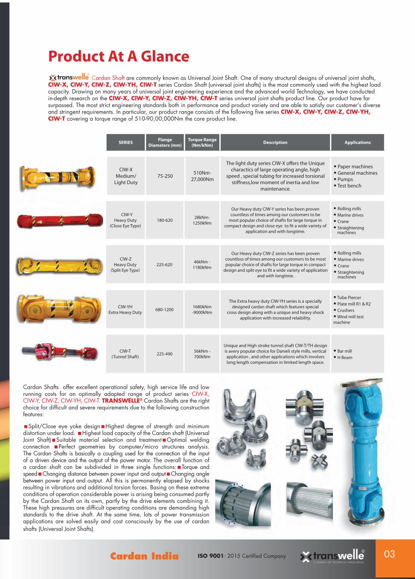
Product At A Glance
Cardan Shafts offer excellent operational safety, high service life and low running costs for an optimally adapted range of product series CIW-X, CIW-Y, CIW-Z, CIW-YH, CIW-T. TRANSWELLE® Cardan Shafts are the right choice for diffi cult and severe requirements due to the following construction features:
Split/Close eye yoke design Highest degree of strength and minimum distortion under load. Highest load capacity of the Cardan shaft (Universal Joint Shaft) Suitable material selection and treatment Optimal welding connection Perfect geometries by computer/micro structures analysis. The Cardan Shafts is basically a coupling used for the connection of the input of a driven device and the output of the power motor. The overall function of a cardan shaft can be subdivided in three single functions: Torque and speed Changing distance between power input and output Changing angle between power input and output. All this is permanently elapsed by shocks resulting in vibrations and additional torsion forces. Basing on these extreme conditions of operation considerable power is arising being consumed partly by the Cardan Shaft on its own, partly by the drive elements combining it. These high pressures are diffi cult operating conditions are demanding high standards to the drive shaft. At the same time, lots of power transmission applications are solved easily and cost consciously by the use of cardan shafts (Universal Joint Shafts).
Cardan Shaft are commonly known as Universal Joint Shaft. One of many structural designs of universal joint shafts, CIW-X, CIW-Y, CIW-Z, CIW-YH, CIW-T series Cardan Shaft (universal joint shafts) is the most commonly used with the highest load capacity. Drawing on many years of universal joint engineering experience and the advanced world Technology, we have conducted in-depth research on the CIW-X, CIW-Y, CIW-Z, CIW-YH, CIW-T series universal joint shafts product line. Our product have far surpassed. The most strict engineering standards both in performance and product variety and are able to satisfy our customer’s diverse and stringent requirements. In particular, our product range consists of the following fi ve series CIW-X, CIW-Y, CIW-Z, CIW-YH, CIW-T covering a torque range of 510-90,00,000Nm the core product line.
A SYMBOL OF TECHNICAL EXCELLENCE
03ISO 9001: 2015 Certifi ed CompanyCardan India
SERIES FlangeDiameters (mm)
Torque Range (Nm/kNm) Description Applications
CIW-XMedium/
Light Duty75-250 510Nm-
27,000Nm
The light duty series CIW-X off ers the Unique charactics of large operating angle, high
speed , special tubing for increased torsional stiff ness,low moment of inertia and low
maintenance.
• Paper machines• General machines• Pumps• Test bench
CIW-YH Extra Heavy Duty 680-1200 1680kNm
-9000kNm
The Extra heavy duty CIW-YH series is a specially designed cardan shaft which features special
cross design along with a unique and heavy shock application with increased relaibility.
• Tube Piercer• Plate mill R1 & R2• Crushers• Wind mill test machine
CIW-T (Tunnel Shaft) 225-490 56kNm -
700kNm
Unique and High stroke tunnel shaft CIW-T/TH design is avery popular choice for Danieli style mills, vertical application , and other applications which involves long length compensation in limited length space.
• Bar mill• H Beam
CIW-YHeavy Duty
(Close Eye Type) 180-620 28kNm-
1250kNm
Our Heavy duty CIW-Y series has been proven countless of times among our customers to be
most popular choice of shafts for large torque in compact design and close eye to fi t a wide variety of
application and with longtime.
• Rolling mills• Marine drives• Crane• Straightening machines
CIW-ZHeavy Duty
(Split Eye Type) 225-620 46kNm -
1180kNm
Our Heavy duty CIW-Z series has been proven countless of times among our customers to be most popular choice of shafts for large torque in compact
design and split eye to fi t a wide variety of application and with longtime.
• Rolling mills• Marine drives• Crane• Straightening machines

04 ISO 9001: 2015 Certifi ed Company Cardan India
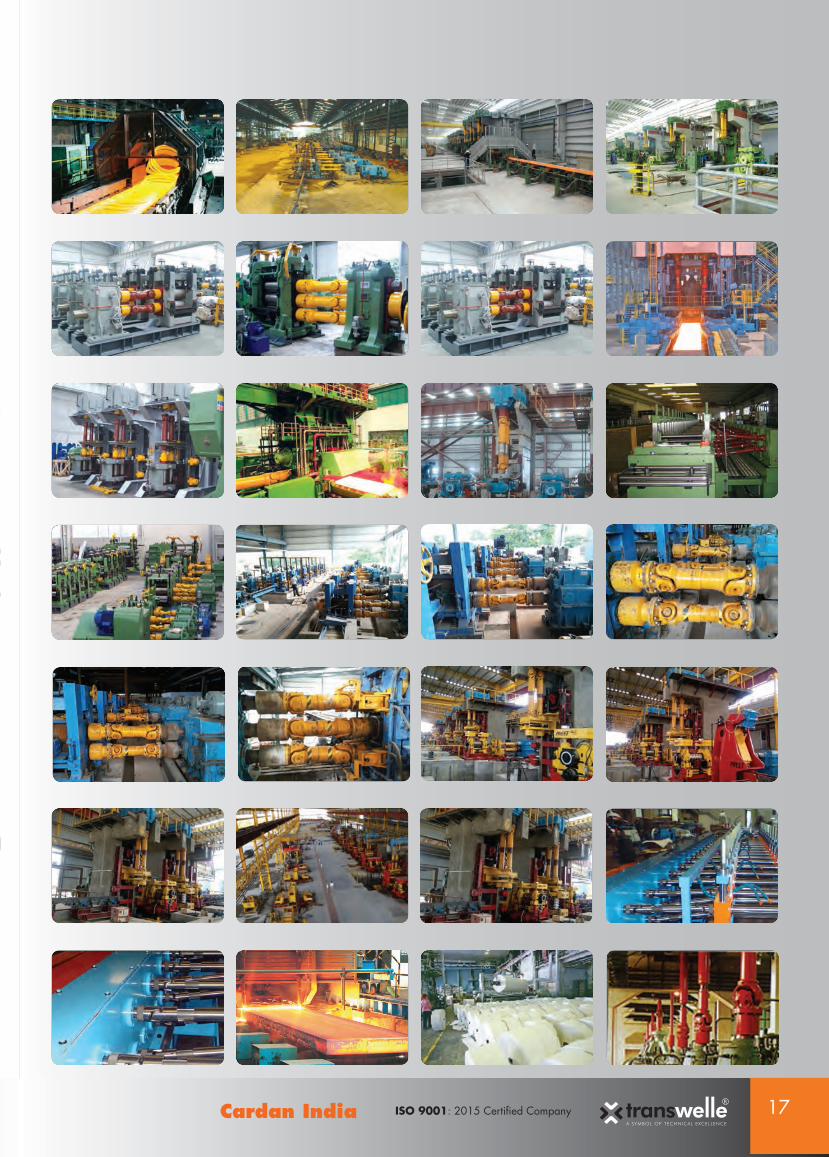
Manufacturing/Assembling Facility:A state-of-art manufacturing plant equipped with high productive and precision machine like CNC Lathes, CNC Machining Centre, Horizontal Boring Machine, Broaching Machine, Milling Machine, Semi Automatic Spline Cutting Machine, Dynamic Balancing Machine etc. supported with conventional machines, EOT Crane and complete modern hi-tech tool room. Layouts of manufacturing shop and machine have been made in a fashion to minimize the movement of material.
Process:Total quality management as per ISO 9001:2015 has been implemented from the fi rst day of commercial production. on a priority basis. A competent authority of international repute is already engaged in the accreditation process. Product are optimally designed on CAD/PRO-E after a thorough analysis of the applications and user requirements. Each product is manufactured through systematic process planning and quality control systems to ensure high reliability and meeting customer requirements. Cardan Shafts are tailor-made according to the individual requests of the customers. The shafts welded by specialists will be checked with a radiographic test machine and dynamically balanced all material pass out through ultrasonic test with experts. After that, they will be lubricated depending on the request of the customer and of the fi eld of application and fi nally they will be painted. Owing to the fl exibility during the process of manufacture, the corresponding stock-keeping, the commitment of the employees and the permanent customer orientation, we are able to grant every customer the best service. The fi nal result will be always best quality cardan shafts.
Quality Assurance Plan: Starting from the design and until the painting, each production step is controlled and verifi ed in order to guarantee an excellent, top quality product. All the universal shafts produced must meet a series of strict controls, starting from the quality of the raw material upto dynamic balancing, where the application requests it. . Our company offers its customers the know-how and the experience in the fi eld of the industrial design, to optimise and integrate its products so as to increase the effi ciency of the plants. We offer our technical support during the design, the installation the maintenance and the evaluation of the performance. Each product is manufactured as per the quality assurance plan derived in line with stringent quality standards and customers requirement. Major steps involved in quality control systems are:
A. Thorough inspection of raw materials, sub-contract and bought out items
B. In-process inspection of components and process control during manufacturing
C. Inspection in sub-assembly and assembly stages
D. Finished product inspection and testing
The plant is equipped with measuring instruments of internationally reputed manufacturers and special testing instrument like Hardness Tester, Ultrasonic Flow Detector, Tensile Tester, Micro Structure Tester, Chemical Testing, M.P.T Balancing Machine, etc.

05ISO 9001: 2015 Certifi ed CompanyCardan India

06 ISO 9001: 2015 Certifi ed Company Cardan India
Technical Data and sizes
CIW-X SERIESCardan Shaft | Universal Joints Shafts | CLOSE EYE & SIDE BOLT TYPE
Light - Medium Duty Design
Shaft Size Unit CIW X
75 / 80CIW-X
90CIW-X
100CIW-X
120CIW-X
130CIW-X
146CIW-X
150CIW-X
175CIW-X
180CIW-X 180H
CIW-X 204
CIW-X 204H
CIW-X 225
CIW-X 230
CIW-X 242
CIW-X 250
Tn Nm 510 810 1220 2350 3400 4600 5600 9000 10000 14000 15000 22000 24000 25200 27000 27000
Tf Nm 250 400 600 1160 1700 2300 2800 4500 5000 7000 7500 11000 12000 12600 13500 13500
β ° 30° 30° 30° 30° 25° 22° 30° 22° 20° 20° 22° 22° 25° 20° 18° 18°
Df mm 75 90 100 120 130 146 150 175 180 180 204 204 225 230 242 250
D mm 72 92 100 98 112 146 112 153 160 160 170 170 170 170 170 170
D1+_0.1mm mm 62 74.5 84 101.5 110 120 130 155.5 155.5 155.5 184 184 196 205 210 218
D2 H9 mm 42 47 57 75 90 95 90 132 95 110 170 140 140 140 140 140
t mm 2 2.5 2.5 2.5 3 3 3 2 3 3 1 3 3 3 3 3
k mm 5.5 6 8 8 10 10 10 10 14 16 10 10 15 15 15 15
H + 0.2 mm 6 6.5 8.5 8.5 10.5 12.5 12.5 10 13 14.1 14.1 16 16 16 16 17
n no 6 4 6 8 8 4 8 8 8 8 8 8 8 8 8 8
Lm mm 45 52 55 63 82 63.5 82 70 85 90 76.2 92 90 90 95 95
D3 mm 50*3 50*3 68*5 68*5 95*5 95*5 95*5 100*7 100*10 106*10 106*8 115*8 120*10 125*10 125*10 125*12
SAE SERIES 1310 1410 1480 1550 1510 1550 1510 1610 1610 Spl 1700 1700 1800 1800 Spl STD 1810 1810Spl
DIN SERIES 75 90 100 120 130 146 150 175 180 180 204 204 225 230 242 250
A type L mm 390 410 440 480 500 500 500 550 560 600 580 620 625 650 680 680
Lv mm 40 40 50 60 80 70 80 80 80 80 100 100 110 120 140 140
B Type mm 325 375 400 425 450 450 450 500 500 540 520 560 560 600 620 650
C Type mm 180 208 220 246 328 254 328 280 340 380 380 380 380 380 380 380
Notations:L = Standard length or compressed lengthfor designs with length compensationLv = Length compensationTn = Nominal torque (Yield torque 50% over Tn)Tf = Fatigue torque i.e permissible torque as determinedaccording to fatigue strength under riversing loadsβ = Maximum defl ection anglen = Number of holes* Note : please consult us for customization regarding length,length compensation and fl ange connection [DIN or SAE etc.]

07ISO 9001: 2015 Certifi ed CompanyCardan India
Type C:
Shaft fl anged without length compensation design
Type B:
Welded shaft without length compensation design
Type A:
Welded shaft with length compensation design

08 ISO 9001: 2015 Certifi ed Company Cardan India
Technical Data and sizes
CIW-Y SERIESCardan Shaft | Universal Joints Shafts | CLOSE EYE TYPE
Heavy Duty Design
Shaft Size Unit CIW-Y 180 CIW-Y 204 CIW-Y 225 CIW-Y 250 CIW-Y 285 CIW-Y 315 CIW-Y 350 CIW-Y 390 CIW-Y 440 CIW-Y 490 CIW-Y 550 CIW-Y 620
Tn kNm 28 40 56 80 120 160 225 320 500 700 1000 1250
Tf kNm 14 20 28 40 58 80 110 160 250 350 500 625
β ° 15° 15° 15° 15° 15° 15° 15° 15° 15° 15° 15° 15°
Df mm 180 200 225 250 285 315 350 390 440 490 550 620
D mm 180 200 225 250 285 315 350 390 440 490 550 620
D1+_0.1mm mm 155.5 184 196 218 245 280 310 345 390 435 492 555
D2 H9 mm 105 120 135 150 170 185 210 235 255 275 320 380
t mm 5 5 5 6 7 8 8 8 10 12 12 15
k mm 17 18 20 25 27 32 35 40 42 47 50 55
H+0.2mm mm 17 17 17 19 21 23 23 25 28 31 31 38
n No. 8 8 8 8 8 10 10 10 16 16 16 16
Lm mm 105 110 125 140 160 180 195 215 260 290 305 340
D3 mm 117*10.5 130*11.5 159*10.5 180*12.5 203*14.5 219*16.7 245*19 273*21 325*24 351*31 402*30 426*40
b e9 mm 24 28 32 40 40 40 50 70 80 90 100 100
g mm 7 8 9 12.5 15 15 16 18 20 22.5 22.5 25
A type L mm 800 900 1000 1060 1270 1390 1520 1530 1690 1850 2060 2280
Lv mm 100 120 140 140 140 140 150 170 190 190 240 250
B Type L mm 530 590 640 730 840 930 1000 1010 1130 1240 1400 1520
C Type L mm 420 440 500 560 640 720 780 860 1040 1080 1220 1360
D Type L mm 580 620 690 760 860 970 1030 1120 1230 1360 1550 1720
E Type L mm 850 940 1050 1120 1320 1440 1550 1710 1880 2050 2310 2540
Lv mm 100 120 140 140 140 140 150 170 190 190 240 250
Notations:L = Standard length or compressed lengthfor designs with length compensationLv = Length compensationTn = Nominal torque (Yield torque 50% over Tn)Tf = Fatigue torque i.e permissible torque as determinedaccording to fatigue strength under riversing loadsβ = Maximum defl ection anglen = Number of holes* Note : please consult us for customization regarding length,length compensation and fl ange connection [DIN or SAE etc.]

09ISO 9001: 2015 Certifi ed CompanyCardan India
Type B:
Short fl exible type
Type C:
Long non-fl exible
Type D:
Short non-fl exible
Type E:
Long fl exibledouble fl ange
Type A:
Long fl exible type
Hirth Serrations

10 ISO 9001: 2015 Certifi ed Company Cardan India
Technical Data and sizes
CIW-Z SERIESCardan Shaft | Universal Joints Shafts | SPLIT EYE TYPE
Heavy Duty Design
Shaft Size Unit CIW Z-225 CIW-Z 250 CIW-Z 285 CIW-Z 315 CIW-Z 350 CIW-Z 390 CIW-Z 435 CIW-Z 480 CIW-Z 550 CIW-Z 620
Tn kNm 46 70 96 132 220 310 460 540 730 1180
Tf kNm 23 35 47 66 110 155 230 270 360 565
β º 15° 15° 15° 15° 15° 15° 10° 10° 10° 10°
A mm 225 250 285 315 350 390 440 490 550 620
K mm 225 250 285 315 350 390 440 490 550 620
B+_ 0. Tmm mm 196 218 245 280 310 345 385 425 492 555
CH7 mm 140 140 175 175 220 235 255 275 320 380
F mm 5 6 7 8 8 9 10 12 12 12
G mm 20 24 27 32 35 40 42 47 50 55
H + 0.2mm mm 17 19 21 23 23 25 28 31 31 38
n No 8 8 8 10 10 10 16 16 16 16
M mm 110 130 140 155 170 190 210 230 250 270
S mm 130*12 160*14 185*16 202*17 220*22 245*25 270*25 295*30 320*32 355*40
X e9 mm 32 36 40 40 50 70 80 90 100 100
Y mm 9 12.5 15* 15* 16 18 20 22.5 22.5 25
A type Lz mm 800 950 1080 1260 1350 1550 1690 1850 2120 2340
Lz2 mm 140 140 140 170 170 170 190 190 210 250
B Type Lz mm 540 680 780 900 960 1090 1210 1310 1500 1660
C Type Lz mm 500 560 600 640 680 760 840 920 1000 1080
D Type Lz mm 680 760 810 870 920 1040 1130 1240 1350 1460
E Type Lz mm 840 890 1130 1320 1400 1610 1740 1910 2170 2400
Lz2 mm 140 140 140 170 170 170 190 190 210 250
Notations:Lz = Standard length or compressed lengthfor designs with length compensationLz2 = Length compensationTn = Nominal torque (Yield torque 50% over Tn)Tf = Fatigue torque i.e permissible torque as determinedaccording to fatigue strength under riversing loadsβ = Maximum defl ection anglen = Number of holes* Note : please consult us for customization regarding length,length compensation and fl ange connection [DIN or SAE etc.]

11ISO 9001: 2015 Certifi ed CompanyCardan India
Type B:
Short fl exible type
Type C:
Short non-fl exible
Type D:
Long non-fl exible
Type E:
Long fl exible double fl ange
Type A:
Long fl exible type
Hirth Serrations

12 ISO 9001: 2015 Certifi ed Company Cardan India
Technical Data and sizes
CIW-T SERIESCardan Shaft | Universal Joints Shafts | TUNNEL TYPE | LONG SPLINE
Heavy Duty Design
CIW-TS SERIES
Model Dfx/Dfy Tn kN.m Tf kN.m β (° ) Lv(mm) Lmin Dfx Dtx D2x bx tx gx Kx Lm(x) Dfy Ly
CIW-T 225 225/315 56 28
5° /15°
650 920 225 196 105 32 5 9 20 125 315 190
CIW-T 250 250/330 80 40 700 1020 250 218 115 40 5 12.5 25 140 330 200
CIW-T 285 285/390 120 58 750 1140 285 245 135 40 7 15 27 160 390 230
CIW-T 315 315/435 160 80 750 1300 315 280 150 40 7 15 32 180 435 250
CIW-T 350 350/480 225 110 800 1445 350 310 165 50 8 16 35 195 480 290
CIW-T 390 390/520 320 160 800 1605 390 345 185 70 8 18 40 215 520 320
CIW-T 440 440/600 500 250 900 1760 435 385 200 80 10 20 42 260 600 390
CIW-T 490 490/650 700 350 900 1955 480 425 225 90 12 22.5 47 290 650 410
Model Dfx/Dfy Tn kN.m Tf kN.m β (° ) Lv(mm) Lmin Dfx Dtx D2x bx tx gx Kx Lm(x) Dfy Lz
CIW-TS 225 225/315 50 28
5° /15°
650 260 225 196 105 32 5 9 20 125 315 90
CIW-TS 250 250/330 71 40 700 285 250 218 115 40 5 12.5 25 140 330 100
CIW-TS 285 285/390 100 58 750 325 285 245 135 40 7 15 27 160 390 110
CIW-TS 315 315/435 150 80 750 360 315 280 150 40 7 15 32 180 435 130
CIW-TS 350 350/480 212 110 800 400 350 310 165 50 8 16 35 195 480 130
CIW-TS 390 390/520 300 160 800 445 390 345 185 70 8 18 40 215 520 140
CIW-TS 440 440/600 425 250 900 500 435 385 200 80 10 20 42 260 600 170
CIW-TS 490 490/650 560 350 900 570 480 425 225 90 12 22.5 47 290 650 170
Model(mm) (kg)
Dty D2y by ty gy ky Lm(y) n1-d1 n2-d2 S D3 V Ry Lmin 100mm
CIW-T 225 285 220 32 5 9 28 140 8-ф17 8-ф17 102.18 146 395 315 215 6.4
CIW-T 250 315 240 40 7 12.5 30 150 8-ф19 8-ф19 117.72 159 435 330 283 8.5
CIW-T 285 355 270 40 8 15 40 170 8-ф21 8-ф21 127.7 180 480 390 400 10
CIW-T 315 390 300 40 8 15 42 190 10-ф23 10-ф23 137.5 203 565 435 533 11.6
CIW-T 350 435 335 50 10 16 47 210 10-ф23 10-ф23 165.2 219 630 480 721 16.8
CIW-T 390 480 385 70 10 18 50 230 10-ф25 10-ф25 177.24 245 695 520 1013 19.4
CIW-T 440 550 420 80 12 20 60 280 16-ф28 10-ф28 201.25 273 735 600 1410 25
CIW-T 490 595 450 90 15 22.5 60 290 16-ф31 14-ф31 225.25 325 810 650 2040 31.3
Model(mm) (kg)
D1y D2y by ty gy ky Lm(y) n1-d1 n2-d2 S D3 V Ry Lmin 100mm
CIW-TS 225 285 220 32 5 9 28 140 8-ф17 8-ф17 102.18 146 395 315 215 6.4
CIW-TS 250 315 240 40 7 12.5 30 150 8-ф19 8-ф19 117.72 159 435 330 283 8.5
CIW-TS 285 355 270 40 8 15 40 190 8-ф21 8-ф21 127.7 180 480 390 400 10
CIW-TS 315 390 300 40 8 15 42 190 10-ф23 10-ф23 137.5 203 565 435 533 11.6
CIW-TS 350 435 335 50 10 16 47 210 10-ф23 10-ф23 165.2 219 630 480 721 16.8
CIW-TS 390 480 385 70 10 18 50 230 10-ф25 10-ф25 177.24 245 695 520 1013 19.4
CIW-TS 440 550 420 80 12 20 60 280 16-ф28 10-ф28 201.25 273 735 600 1410 25
CIW-TS 490 595 450 90 15 22.5 60 290 16-ф31 14-ф31 225.25 325 810 650 2040 31.3

13ISO 9001: 2015 Certifi ed CompanyCardan India
Notations:L = Standard length or compressed lengthfor designs with length compensationLv = Length compensationTn = Nominal torque (Yield torque 50% over Tn)Tf = Fatigue torque i.e permissible torque as determinedaccording to fatigue strength under riversing loadsβ = Maximum defl ection anglen = Number of holes* Note : please consult us for customization regarding length, length compensation and fl ange connection [DIN or SAE etc.]
ding tion [DIN
CIW-T SERIES
CIW-TS SERIES

14 ISO 9001: 2015 Certifi ed Company Cardan India
Technical Data and sizes
CIW-YH SERIESCardan Shaft | Universal Joints Shafts | CLOSE EYE TYPE
Extra Heavy Duty Design
Shaft Size Unit CIW-YH
680CIW-YH
700CIW-YH
750CIW-YH
780CIW-YH
800CIW-YH
840CIW-YH
900CIW-YH
920CIW-YH
1000CIW-YH
1060CIW-YH
1100CIW-YH
1200
C L 1540 1600 1840 1920 1920 2120 2280 2280 2380 2480 2500 2720
D L 1940 2100 2400 2500 2500 2680 2950 2950 3130 3200 3300 3570
EL 3230 3460 3620 4000 4000 4250 4580 4850 4770 4950 5100 5660
Lv 250 250 250 250 250 250 300 300 300 300 300 300
Tn (kN.m) 1650 1750 2250 2500 2670 3100 3800 4050 5200 6500 6900 9000
Tf (kN.M) 985 1050 1350 1500 1600 1860 2280 2430 3120 3900 4140 5400
β (° ) 15 15 15 15 15 15 15 15 15 15 15 15
D 680 700 750 780 800 840 900 920 1000 1060 1100 1200
Df 680 700 750 780 800 840 900 920 1000 1060 1100 1200
D1 635 635 695 725 745 775 835 855 915 980 1015 1100
D2 (H9) 550 570 610 640 660 710 740 760 840 840 920 1000
D3 560 560 620 660 660 660 750 750 790 800 850 900
Lm 385 400 480 480 480 530 570 570 595 620 625 680
K 70 70 95 95 95 110 120 120 130 130 130 130
n 24 24 24 24 24 24 24 24 20 20 20 20
d 26 26 31 31 36 38 38 38 50 45 50 58
Flange Bolt M24 M24 M30 M30 M30 M36 M36 M36 M48 M42 M48 M56
C -TYPE
D -TYPE
E -TYPE

15ISO 9001: 2015 Certifi ed CompanyCardan India
Selection Information and Speed LimitsSpeed Limit based on limits of Mass Acceleration
When Cardan Shaft (Universal Joint Shaft) are operated at any angle greater than zero, the center section of the universal joint shaft always runs irregularly, being accelerated and decelerated twice in every revolution. The maximum values of mass acceleration torque arising here are dependent on the operating speed and angle of deviation ß and upon the moment of inertia of the cardan shaft section (RPM x ß)To ensure smooth running of the universal joint, especially at idling speed, the mass acceleration torque must not be allowed to exceed the limits.
Speed Limit based on Lateral Critical Speed
In applications where long lengths of shafts are required, the speed is restricted by the lateral critical speed of the center section. This speed is a function of the center tube diameter wall thickness, and the effective length. The maximum operating speed must be less than the lateral critical speed Nc.
Note:Allowable Operating Speed= NC x .75.In many applications, operation at ½ critical speed will also create unacceptable vibration. For these applications the operating speed should be 8% above or below 50% of the maximum indicated. For fl ange-to-fl ange lengths greater than shown, if allowable speed exceeds, contact CARDAN INDIA.
Balancing
All standard universal joints under 300 RPM are supplied unbalanced. Between 300-850 RPM they are balanced if required. Consult factory for further information. Over 850 RPM all universal joints are normally supplied balanced. Please consult the factory for special balancing requirements.
The Selection of Cardan Shaft / Universal Joint ShaftsAccording to standard, use the following methods to select CIW-X, CIW-Y, CIW-Z, CIW-YH, CIW-T series Cardan Shaft (universal joint shaft).Please consult us for selecting other product series.
1. Universal joint shafts are selected according to the load features, calculated torques, bearing life, and operating speed.2. The calculated torque is acquired from Formulas (1), (2) or (1), (3).
Tc=KT……………......(1) Where, Tc = Calculated torque, Nm; T= 9550 Pw/n ……..(2) T = Nominal tarque, Nm;Or T = 7020 PH/n…......(3) Pw = Driving power, kW; PH = Driving power, hp; N = Operating speed, rpm; K = Service factors
3. Generally, universal joint shafts are selected according to the torque to be transmitted on required bearing life. They can also be selected checking their torque strengths or bearing life relation to the requirements of the applied equipment.
3.1Checking the tortional strength using Formula Tc < Tn or Tc < Tf or Tc < Tp…………… (4) Where, Tc = Calculate torque, Nm Tn = Nominal torque, Nm (i.e a theoretic calculated value under these pre-determined conditions) speed of shaft n= 30rpm, defl ected angle B = 3º, and a bearing life LN = 5000 hours under even load, Tf = Permissible torque according to the fat strength under alternating loads. Nm TP = Permissible torque according to the fat strength under pulsating loads, Nm TP = 1.45 Tf
4. When there are simultaneous horizontal and vertical angular misalignments on the universal joint shaft, the composite defl ection angle is calculated using Formula (6);
tgß = tg2ß1 + tg2ß2 …………….(5)
Where, ß = Composite defl ection angle, (º); ß1 = Horizontal defl ection angle, (º); ß2 = Vertical defl ection angle, (º)
5. If the joint diameter of the shaft is 390 mm or less, Formulas (7) and (8) should be used to check the maximum speed in addition to the considerations of torque bearing life.
nmax (nß) ………………………(7) nmax (nL) ………………………( 8) Where, nmax = Maximum operating speed, rpm; (nß) = Maximum permissible speed in relation to operating angle, rpm. (See Figure 1) (nL)= Maximum permissible speed in relation to operating length, rpm. (See Figure 2)
6. If the line speed of the shaft is over 7m/s, dynamic balancing test is requested, normally to a balancing accuracy between G6.3 ~ G16. There are complex variables which effects the balancing grade.
The Installation and Maintenance of Universal Joint Shafts For installation and maintenance of universal joint shaft, please refer to the (Manual for CIW – X, Y, Z, YH, T Series), which is provided in the package boxes with the products.
Service factor type Driven Equipment K
Light shock load Generators, Centrifugal pump, Wood handling, machines Belt conveyors, Ventilators Paper machines, 1.1 to 1.3
Medium shock load Compressors (multi-cyl.) Pumps (multi-cyl.) Small section mills, Continuous wire mills, Conveyor primary drives, 1.3 to 1.8
Heavy shock loadMarine transmissions, Transport roller tables, Continuous tube mills, Continuous working rollertables, Medium section mills, Compressors (single-cyl.) Pumps (single-cyl) Mixers Presses, Straightening machines, Crane drives, Ball mills.
2 to 3
Extra heavy shock load Crane accessory drives, Crushers, Reversing working roller tables, Reeling drives, Scale breakers, Blooming stands. 3 to 5
Extreme shock load Feed roller drives, Plate shears. 6 to 15
Table 10: Service Factors K
3.2 Checking the bearing lifeWhere,LN = Service life, hrs;n= Operating speed, rpm;ß= Joint operating angle in operation, (º);K1 = Prime motor factorElectric motor: K1 = 1 Diesel generator : K1 = 1.2KL + Bearing capacity factorLmin = Min. bearing life, hrs;T = Theoretic torque, kN • m
Using Formula (5) KLLN = ---------------------------------------- X 1010 ≥ L min....(5) K1nß T10/3

16 ISO 9001: 2015 Certifi ed Company Cardan India
Advantages and Features Domestic manufacturer & exporter
High torque capacity
Long bearing life
High operating angle capability
One piece yoke/split yoke and bearing housing construction
Eliminates unnecessary bolted connections and serrations in yokes
Heat treated alloy steel components
Ideal loading across entire bearing length due to balanced defl ection between yokes and cross
Replaceable inner bearing race on size and large signifi cantly reducing cross- maintenance expenses
Available in fi ve basic types
Technical support and engineering services available
Extensive repair facility
Special sizes and designs available upon request
Large sizes available
Metal Industries(Steel, Aluminium, Copper and Brass) Continuous Stands (TMT)
Roughing Stands (TMT)
Intermediate Stands (TMT)
H/V Stand (Housing Less)
Bar and Rod Mills
Cold Reduction
Continuous Casters
Hot Strip Mills
Levelers
Payoff Reels- Pinch Rolls- Coilers- Brush Rolls- Bricles- Flatteners- Slitters
Seamless Pipe Mills
Scale Breakers
Stacker Reclaimer
Side Trimmers
Straighteners
Temper Mills
Tension Reels
Tube Mills
Vertical Edgers
Wire Mills
Shears
Runout Tables- Piercers - Transfer
Conveyors
Cooling Tower Fans
Cranes and Hoists
Crushers
Glass Manufacturing
Paper Mills- Calender Drives- Sizing and Press Rolls- Couch Rolls- Process Pumps, Jumbo press, Pope reel
Vibrating Screen
Coal Washery
Sinter Screen
SMS
Marine Propulsion
Mining Equipment
Oil and Gas Drilling Pumps
Packaging
Plastic Manufacturing - Melt Pumps
Printing Presses
Pumps- Irrigation - Lift - Sewage
Railway Drives
Rubber Processing - Mixers - Calenders
Shredders
Textile Equipment
Below a partial list of applications for the
Transwelle Cardan ShaftR
17ISO 9001: 2015 Certifi ed CompanyCardan India

18 ISO 9001: 2015 Certifi ed Company Cardan India
FLANGE DESIGN
U. J CROSS DESIGN
Face key Hirth Serration Integral Face Pad Welded
Create onsite confi rmations pre repairing report. After confi rmation estimate shall be offered. Contact logistics for shipment of the repairing material. Visual checking, dismantling, cleaning, and to issue inspection report with quotation. Receive fi nal work order, replacement of damage parts as per international product standard. Assembling, dynamic balancing, issue internal inspection report, painting, fi nal packaging and dispatch. Customer feedback.
Product Recycling Process / Repair
COMPANION HUB DESIGN
19ISO 9001: 2015 Certifi ed CompanyCardan India
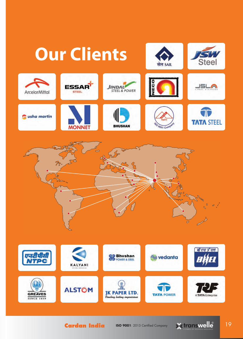
Our Clients

CARDAN INDIAG.T. Road, Panagarh, Durgapur-713148,Dist.: Burdwan, West Bengal (India)
Tel - +91-343 2524728 / 29 Telefax - +91 343-2527065H.P +91 9800046890 / +91 9434333326 / +91 9832288664Email: [email protected] / [email protected]
www.cardanindia.com
V- 6.0 /16 This supercedes all previous editionLike & Follow Us - Dimensions, data and illustrations are provided for information purposes only. Subject to change.
prin
t and
erso
n 98
3157
8981