cardin elettronica spa via raffaello, 36 3 020 san
TRANSCRIPT
AUTOMAZIONE PER PORTE BASCULANTI A CONTRAPPESIAUTOMATION FOR COUNTERBALANCEd GARAGE dOORS
AUTOMATION dE PORTES BASCULANTES à CONTREPOIdSGARAGENTORANTRIEB FÜR SCHWING- UNd KIPPTORE
AUTOMATIZACIÓN PARA PUERTAS BASCULANTES POR CONTRAPESOS
ATTENTION! Before installing this device read the following instructions carefully!
Installation example Page 2Important remarks Page 19Installation instructions Page 19-21Manual release mechanism Page 21Electronic programmer Page 21Electrical connection Page 21-22Programming procedure Page 23 Automatic repositioning Page 24Display mode Page 24Remote control Page 25Function modes Page 25Battery powered operation Page 26Indications on the display Page 27Technical specifications Page 56
ZV
L471
.01
Mod
: 23-
02-2
005
ENGLISH
CARdIN ELETTRONICA spa Via Raffaello, 36 3020 San Vendemiano (TV) ItalyTel: +39/0438.4040-4088Fax: +39/0438.4083email (Italian): [email protected] (Europe): [email protected]: www.cardin.it
Instruction manual SeriesZVL47.0
Series Date
0-0-2005Questo prodotto è stato testato e collaudato nei laboratori della casa costruttrice, la quale ne ha verificato la perfetta corrispondenza delle caratteristiche con quelle richieste dalla normativa vigente.This product has been tried and tested in the manufacturer's laboratory who have verified that the product conforms in every aspect to the safety standards in force.Ce produit a été testé et essayé dans les laboratoires du fabriquant. Pour l'installer suivre attentivement les instructions fournies.Dieses Produkt wurde in den Werkstätten der Herstellerfirma auf die perfekte Übereinstimmung ihrer Eigenschaften mit den von den geltenden Normen vorgeschriebenen getestet und geprüft.Este producto ha sido probado y ensayado en los laboratorios del fabricante, que ha comprobado la perfecta correspondencia de sus características con las contempladas por la normativa vigente.
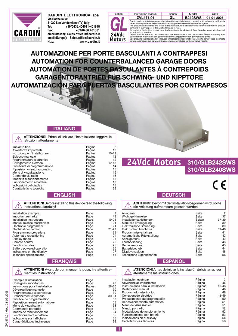
GL24VdcMotors
GL B242SWSModel
24Vdc Motors 30/GLB242SWS30/GLB240SWS
ATTENTION! Avant de commencer la pose, lire attentive-ment les instructions!
Exemple d’installation Page 2Consignes importantes Page 28Instructions pour l'installation Pages 28-30Déverrouillage manuelle Page 30Programmateur électronique Page 30Branchement électrique Page 30-31Procédé de programmation Page 32Repositionnement automatique Page 33Menu de visualisation Page 33Commande por radio Page 34Modes de fonctionnement Page 34Fonctionnement à batterie Page 35Indications sur l’afficheur Page 36Caractéristiques techniques Page 56
FRANÇAIS
ATTENZIONE! Prima di iniziare l'installazione leggere le istruzioni attentamente!
Impianto tipo Pagina 2Avvertenze importanti Pagina 10Istruzioni per l'installazione Pagina 10-12Sblocco manuale Pagina 12Programmatore elettronico Pagina 12Collegamento elettrico Pagina 12-13Procedura di programmazione Pagina 14 Riposizionamento automatico Pagina 15Menu di visualizzazione Pagina 15Comando via radio Pagina 16Modalità di funzionamento Pagina 16Funzionamento a batteria Pagina 17Indicazioni del display Pagina 18Caratteristiche tecniche Pagina 56
ITALIANO
ACHTUNG! Bevor mit der Installation begonnen wird, sollte die Anleitung aufmerksam gelesen werden!
Anlagenart Seite 2Wichtige Hinweise Seite 37Installationsanleitungen Seiten 37-39Manuelle Entriegelung Seite 39Elektronische Steuerung Seite 39Elektrischer Anschluss Seite 39-40Programmierverfahren Seite 41Automatische Rückstellung Seite 42Anzeigemenu Seite 42Fernbedienung Seite 43Betriebsmodus Seite 43Batteriebetrieb Seite 44Displayanzeigen Seite 45Technische Eigenschaften Seite 56
dEUTSCH
¡ATENCIÓN! Antes de iniciar la instalación del sistema, leer atentamente las instrucciones.
Instalación estándar Página 2Advertencias importantes Página 46Instrucciones para la instalación Páginas 46-48Desbloqueo manual Página 48Programador electrónico Página 48Conexionado eléctrico Página 48-49Procedimiento de programación Página 50Reposicionamiento automático Página 51Menú de visualización Página 51Mando por radio Página 52Modalidades de funcionamiento Página 52Funcionamiento con batería Página 53Indicaciones en el display Página 54Características técnicas Página 56
ESPAÑOL

2
SC
ALA
: :2
pro
do
tti technocity (lam
p. fo
tocellule ecc.)
GL20
-09-2000
dI0045
Descrip
tion :
Prod
uct Cod
e :
Date :
Draw
ing numb
er :
P.J.Heath
CA
RD
IN E
LET
TR
ON
ICA
S.p
.A - 31020 S
an Vendem
iano (T
V) Italy - via R
affaello, 36 Tel: 0438/401818 F
ax: 0438/401831
Draft :
All rights reserved
. Unauthorised
copying or use of the inform
ation contained in this d
ocument is p
unishable b
y law
INS
TALLA
ZIO
NE
TIP
O G
LB242
3x
5
3x
2x + RG58
Tx
Rx
4
2x
3
7 2x,5+T
230V - 50Hz
8
6
2
9
LEGENdA1 Motoriduttore con centrale incorporata2 Fotocellula interna3 Scatola di derivazione4 Selettore a chiave5 Lampeggiatore esterno 6 Interruttore onnipolare con apertura contatti min. 3 mm7 Costa sensibile antischiacciamento8 Antenna esterna (Cavo coassiale RG58 Impedenza 50Ω) 9 Sblocco a cordino
LEGENd1 Geared motor with on board electronics2 Internal photocells 3 Shunt box4 Mechanical selector switch5 Warning lights6 All pole circuit breaker with a minimum of 3 mm between the contacts7 Anticrush safety buffer8 External antenna (RG58 coaxial cable with an impedance of 50Ω)9 Manual cord release mechanism
NOMENCLATURE1 Motoréducteur avec programmateur intégré2 Cellule photoélectrique interne3 Boîte de dérivation4 Sélecteur à clé5 Clignoteur externe6 Interrupteur omnipolaire avec ouverture des contacts d’au moins 3
mm7 Bord de sécurité anti-coincement8 Antenne externe (câble coaxial RG58 - Impédance 50Ω)9 Dispositif de déverrouillage à câble
ZEICHENERKLäRUNG1 Getriebemotor mit eingebauter Steuerung2 Interne Lichtschranke3 Verteilerdose4 Schlüsselschalter5 Externes Blinklicht6 allpoliger Schalter mit Kontaktenabstand von mindestens 3mm7 Sicherheitsleiste zum Schutz vor Quetschungen8 Außenantenne (Koaxialkabel RG58 Impedanz 50Ω)9 Seilzugentriegelung
LEYENdA1 Motorreductor con programador incorporado2 Fotocélula interior 3 Caja de derivación4 Selector con llave5 Luz intermitente exterior6 Interruptor omnipolar con apertura entre los contactos de 3 mm
como mín.7 Protector sensible antiaplastamiento8 Antena exterior (Cable coaxial RG58 Impedancia 50Ω)9 Desbloqueo por cordón
IMPIANTO TIPO - INSTALLATION ExAMPLE - ExEMPLE d'INSTALLATION - ANLAGENART - INSTALACIÓN ESTÁNdAR
3
Installazione motore centrale
GL20
2-09-2000
dI0002 Description :
Product Code :
Date:
drawing number :
P.J.Heath
CARdIN ELETTRONICA S.p.A - 31020 San Vendemiano (TV) Italy - via Raffaello, 36 Tel: 0438/401818 Fax: 0438/401831
Draft :
All rights reserved. Unauthorised copying or use of the information contained in this document is punishable by law
GL20
36/GL20SB
Accessori per motore centrale
GL20
2-09-2000
dM0007 Description :
Product Code :
Date :
Drawing number :
P.J.Heath
CARdIN ELETTRONICA S.p.A - 31020 San Vendemiano (TV) Italy - via Raffaello, 36 Tel: 0438/401818 Fax: 0438/401831
Draft :
All rights reserved. Unauthorised copying or use of the information contained in this document is punishable by law
36/GLO2Ad
36/GLOPS
36/GLO4A36/GLO3A
36/GLO2Ad
36/GLOTG
Z
36/GLOPS36/GLOPS2
INSTALLAZIONE dI MOTORE CENTRALE (PORTA dEBORdANTE) - INSTALLING MOTOR CENTRALLY (NON FLUSH-FITTING dOOR) MONTAGE d’UN MOTEUR CENTRAL (PORTE dÉBORdANTE) - INSTALLATION VON ZENTRALEN MOTOR (ÜBERRAGENdES TOR)
INSTALACIÓN dE MOTOR CENTRAL (PUERTA dESBORdANTE)
2

4
Installazione centrale motore (non debord.)
GL20
2-09-2000
dI000 Description :
Product Code :
Date :
Drawing number :
P.J.Heath
CARdIN ELETTRONICA S.p.A - 31020 San Vendemiano (TV) Italy - via Raffaello, 36 Tel: 0438/401818 Fax: 0438/401831
Draft :
All rights reserved. Unauthorised copying or use of the information contained in this document is punishable by law
GL20
=
=
36/GL20SB
Accessori per motore centrale
GL20
2-09-2000
dM0004 Description :
Product Code :
Date :
Drawing number :
P.J.Heath
CARdIN ELETTRONICA S.p.A - 31020 San Vendemiano (TV) Italy - via Raffaello, 36 Tel: 0438/401818 Fax: 0438/401831
Draft :
All rights reserved. Unauthorised copying or use of the information contained in this document is punishable by law
36/GLO6A
36/GLOPS
36/GLO6A
36/GLOTG
Z
36/GLOPS236/GLOPS
INSTALLAZIONE dI MOTORE CENTRALE (PORTA NON dEBORdANTE) - INSTALLING MOTOR CENTRALLY (FLUSH -FITTING dOOR)MONTAGE d’UN MOTEUR CENTRAL (PORTE NON dÉBORdANTE) - INSTALLATION VON ZENTRALEN MOTOR (NICHTÜBERRAGENdES TOR)
INSTALACIÓN dE MOTOR CENTRAL (PUERTA NO dESBORdANTE)
3
5
Installazione laterale 2 motore (debord.)
GLB242
23-02-2005
dI0367 Description :
Product Code :
Date :
Drawing number :
P.J.Heath
CARdIN ELETTRONICA S.p.A - 31020 San Vendemiano (TV) Italy - via Raffaello, 36 Tel: 0438/401818 Fax: 0438/401831
Draft :
All rights reserved. Unauthorised copying or use of the information contained in this document is punishable by law
GLB
36/GL20SB
Accessori per motore laterale
GL20
25-2-2000
dM0520 Description :
Product Code :
Date :
Drawing number :
P.J.Heath
CARdIN ELETTRONICA S.p.A - 31020 San Vendemiano (TV) Italy - via Raffaello, 36 Tel: 0438/401818 Fax: 0438/401831
Draft :
All rights reserved. Unauthorised copying or use of the information contained in this document is punishable by law
36/GLO2Ad
36/GLO4A 36/GLO3A
36/GLOPS
36/GLOPS
36/GLO2Ad
36/GLOCGL
Ø ext.26,9 x Ø int.22,2
36/GLOPS2
INSTALLAZIONE dI MOTORE LATERALE - INSTALLING LATERAL MOTOR - MONTAGE d’UN MOTEUR LATÉRALE INSTALLATION VON SEITLICHEN MOTOR - INSTALACIÓN dE MOTOR LATERAL
4

6
Installazione laterale 2 motore (debord.)
GLB242/240
23-02-2005
dI0368 Description :
Product Code :
Date :
Drawing number :
P.J.Heath
CARdIN ELETTRONICA S.p.A - 31020 San Vendemiano (TV) Italy - via Raffaello, 36 Tel: 0438/401818 Fax: 0438/401831
Draft :
All rights reserved. Unauthorised copying or use of the information contained in this document is punishable by law
GLB242/240
36/GL20SB
30/GLB240SWS30/GLB242SWS
36/GL20SB
Accessori per motore laterale
GL20
25-09-2000
dM0025 Description :
Product Code :
Date :
Drawing number :
P.J.Heath
CARdIN ELETTRONICA S.p.A - 31020 San Vendemiano (TV) Italy - via Raffaello, 36 Tel: 0438/401818 Fax: 0438/401831
Draft :
All rights reserved. Unauthorised copying or use of the information contained in this document is punishable by law
36/GLO2Ad
36/GLO4A
36/GLOPS
36/GLO3A
36/GLOPS
36/GLOPS
36/GLOPS
36/GLO2Ad
36/GLOPS2
36/GLOPS2
INSTALLAZIONE dI 2 MOTORI (PORTA dEBORdANTE) - INSTALLING 2 MOTORS (NON FLUSH-FITTING dOOR) MONTAGE dE dEUx MOTEURS (PORTE dÉBORdANTE) - INSTALLATION VON 2 MOTOREN (ÜBERRAGENdES TOR)
INSTALACIÓN dE 2 MOTORES (PUERTA dESBORdANTE)
5

7
G
H
I
M
I
R
O
F
P
Montaggio maniglia di sblocco (nuovo sblocco)
GL20
02-02-2000
dM0466 Description :
Product Code :
Date :
Drawing number :
P.J.Heath
CARdIN ELETTRONICA S.p.A - 31020 San Vendemiano (TV) Italy - via Raffaello, 36 Tel: 0438/401818 Fax: 0438/401831
Draft :
All rights reserved. Unauthorised copying or use of the information contained in this document is punishable by law
GL20
E
d
E
Montaggio maniglia di sblocco (nuovo sblocco)
GL20
02-02-2000
dM0465 Description :
Product Code :
Date :
Drawing number :
P.J.Heath
CARdIN ELETTRONICA S.p.A - 31020 San Vendemiano (TV) Italy - via Raffaello, 36 Tel: 0438/401818 Fax: 0438/401831
Draft :
All rights reserved. Unauthorised copying or use of the information contained in this document is punishable by law
GL20
C
00
mm
A
B
Montaggio maniglia di sblocco
GL20
02-02-2000
dM055 Description :
Product Code :
Date :
Drawing number :
P.J.Heath
CARdIN ELETTRONICA S.p.A - 31020 San Vendemiano (TV) Italy - via Raffaello, 36 Tel: 0438/401818 Fax: 0438/401831
Draft :
All rights reserved. Unauthorised copying or use of the information contained in this document is punishable by law
GL20 Posizione sbloccato (a mano)
N
q
S
Montaggio maniglia di sblocco
GL20
02-02-2000
dM054 Description :
Product Code :
Date :
Drawing number :
P.J.Heath
CARdIN ELETTRONICA S.p.A - 31020 San Vendemiano (TV) Italy - via Raffaello, 36 Tel: 0438/401818 Fax: 0438/401831
Draft :
All rights reserved. Unauthorised copying or use of the information contained in this document is punishable by law
GL20 Posizione sbloccato (a cordino)
Montaggio maniglia di sblocco
GL20
02-02-2000
dM053 Description :
Product Code :
Date :
Drawing number :
P.J.Heath
CARdIN ELETTRONICA S.p.A - 31020 San Vendemiano (TV) Italy - via Raffaello, 36 Tel: 0438/401818 Fax: 0438/401831
Draft :
All rights reserved. Unauthorised copying or use of the information contained in this document is punishable by law
GL20 posizione bloccato
L
SBLOCCO A CORdINO - MANUAL RELEASE CORd - dISPOSITIF dE dÉVERROUILLAGE à CÂBLE SEILZUGENTRIEGELUNG - dESBLOqUEO POR CORdÓN
6
6a
6b
6c

8
SCHEMA ELETTRICO PER MOTORE - WIRING dIAGRAM FOR MOTOR - SCHÉMA ÉLECTRIqUE POUR MOTEUR ELEKTRISCHER SCHALTPLAN FÜR MOTOR - ESqUEMA ELÉCTRICO dE MOTOR
7
M1
M2
LEGENdANS400 External antennaM Motor 1 (pre-wired)M2 Motor 2LC Courtesy light (pre-wired) LP Flashing warning lightsFTC-Rx Photocell receiverFTC-Tx Photocell transmitterSEL Selector switchTB Blocking button
ENCOdEREncoder terminal block connections: Yellow - Grey - Green - Blue -
NOMENCLATUREANS400 Antenne externeM Moteur 1 (pré-câblé)M2 Moteur 2LC Éclairage de zone (pré-câblé) LP ClignoteurFTC-Rx Cellule photoél. récepteur FTC-Tx Cellule photoél. émetteurSEL Sélecteur à cléTB Touche de blocage
ENCOdEURBornier de branchement encodeur:Yellow - jauneGrey - grisGreen - vertBlue - bleu
ZEICHENERKLäRUNGANS400 AußenantenneM Motor 1 (vorverkabelt)M2 Motor 2LC Wachlicht (vorverkabelt) LP BlinklichtFTC-Rx Lichtschrank EmpfängerFTC-Tx Lichtschrank SenderSEL SchlüsselwahlschalterTB Blockiertaste
ENCOdERAnschlussklemmleiste für Encoder:Yellow - GelbGrey - GrauGreen - GrünBlue - Blau
LEYENdAANS400 Antena exteriorM Motor 1 (precableado)M2 Motor 2LC Luz de zona (precableado) LP RelampagueadorFTC-Rx Fotocélula receptorFTC-Tx Fotocélula emisorSEL Selector de llaveTB Botón de bloqueo
ENCOdERPlaca de bornes encoder:Yellow - amarilloGrey - grisGreen - verdeBlue - azul oscuro
LEGENdAANS400 Antenna esternaM Motore 1 (precablato)M2 Motore 2LC Lampada di cortesia (precablata) LP LampeggiatoreFTC-Rx Fotocellula ricevitoreFTC-Tx Fotocellula trasmettitoreSEL Selettore a chiaveTB Tasto di blocco
ENCOdERMorsettiera collegamento encoder:Yellow - gialloGrey - grigioGreen - verdeBlue - blu
9
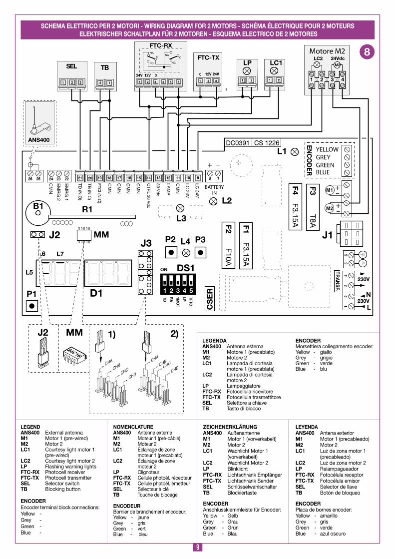
SCHEMA ELETTRICO PER 2 MOTORI - WIRING dIAGRAM FOR 2 MOTORS - SCHÉMA ÉLECTRIqUE POUR 2 MOTEURS ELEKTRISCHER SCHALTPLAN FÜR 2 MOTOREN - ESqUEMA ELECTRICO dE 2 MOTORES
8
M1
M2
LEGENdANS400 External antennaM Motor 1 (pre-wired)M2 Motor 2LC Courtesy light motor 1 (pre-wired) LC2 Courtesy light motor 2LP Flashing warning lightsFTC-Rx Photocell receiverFTC-Tx Photocell transmitterSEL Selector switchTB Blocking button
ENCOdEREncoder terminal block connections:Yellow - Grey - Green - Blue -
NOMENCLATUREANS400 Antenne externeM Moteur 1 (pré-câblé)M2 Moteur 2LC Éclairage de zone moteur 1 (precablato) LC2 Éclairage de zone moteur 2 LP ClignoteurFTC-Rx Cellule photoél. récepteurFTC-Tx Cellule photoél. émetteurSEL Sélecteur à cléTB Touche de blocage
ENCOdEURBornier de branchement encodeur:Yellow - jauneGrey - grisGreen - vertBlue - bleu
ZEICHENERKLäRUNGANS400 AußenantenneM Motor 1 (vorverkabelt)M2 Motor 2LC Wachlicht Motor 1 (vorverkabelt)LC2 Wachlicht Motor 2 LP BlinklichtFTC-Rx Lichtschrank EmpfängerFTC-Tx Lichtschrank SenderSEL SchlüsselwahlschalterTB Blockiertaste
ENCOdERAnschlussklemmleiste für Encoder:Yellow - GelbGrey - GrauGreen - GrünBlue - Blau
LEYENdAANS400 Antena exteriorM Motor 1 (precableado)M2 Motor 2LC Luz de zona motor 1 (precableado) LC2 Luz de zona motor 2LP RelampagueadorFTC-Rx Fotocélula receptorFTC-Tx Fotocélula emisorSEL Selector de llaveTB Botón de bloqueo
ENCOdERPlaca de bornes encoder:Yellow - amarilloGrey - grisGreen - verdeBlue - azul oscuro
LEGENdAANS400 Antenna esternaM Motore 1 (precablato)M2 Motore 2LC Lampada di cortesia motore 1 (precablata) LC2 Lampada di cortesia motore 2 LP LampeggiatoreFTC-Rx Fotocellula ricevitoreFTC-Tx Fotocellula trasmettitoreSEL Selettore a chiaveTB Tasto di blocco
ENCOdERMorsettiera collegamento encoder:Yellow - gialloGrey - grigioGreen - verdeBlue - blu

0
• Il presente manuale si rivolge a persone abilitate all'installazione di "APPARECCHI UTILIZZATORI dI ENERGIA ELETTRICA" e richiede una buona conoscenza della tecnica, esercitata in forma professionale. I materiali usati devono essere certificati e risultare idonei alle condizioni ambientali di installazione.
• Le operazioni di manutenzione devono essere eseguite da personale qualificato. Prima di eseguire qualsiasi operazione di pulizia o di manutenzione, disinserire l'apparecchiatura dalla rete di alimentazione elettrica.
• Le apparecchiature qui descritte dovranno essere destinate solo all'uso per il quale sono state espressamente concepite: "La motorizzazione di basculanti a contrappesi". L’utilizzo dei prodotti e la loro destinazione ad usi diversi da quelli pre-visti e/o consigliati, non è stata sperimentata dal costruttore, pertanto i lavori eseguiti sono sotto la completa responsabilità dell’installatore.
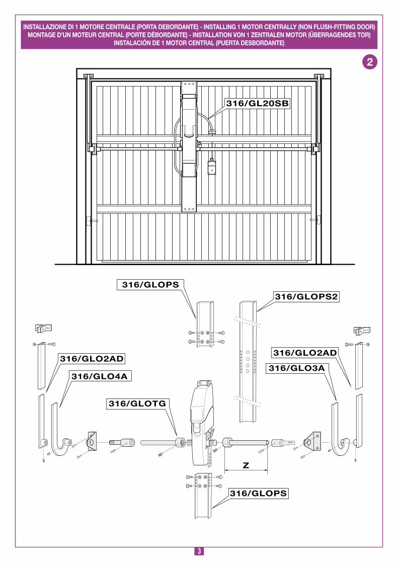
POSSIBILITà d'IMPIEGOIl gruppo è adatto alla motorizzazione di basculanti a telo singolo o snodato. È richiesto l’uso di due gruppi (uno con l'elettronica a bordo 30/GLB242SWS ed uno senza 30/GLB240SWS, comandato dall'altro) per basculanti oltre i 4 m di larghezza e non oltre i 2,7 m di altezza e per basculanti aventi porta pedonale (montaggio laterale).•
• Il costruttore non risponde qualora l'impianto elettrico non risulti conforme alle norme vigenti.
È responsabilità dell’installatore verificare le seguenti condizioni di sicurezza ed effettuare alcuni controlli prima di procedere all’installazione.1) La porta pedonale non si deve aprire involontariamente, ad
esempio per gravità, quando la basculante è aperta.2) L’apparecchiatura non deve essere alimentata quando la porta
pedonale non è completamente chiusa.3) Verificare che non vi siano bordi affilati pericolosi (R=3mm min.).4) Rendere consapevole l’utente che bambini o animali domestici
non devono giocare o sostare nei pressi della porta basculante. Se necessario indicarlo in targa.
5) La bontà della connessione di terra dell’apparecchiatura è fondamentale ai fini della sicurezza elettrica.
6) Per qualsiasi dubbio a riguardo della sicurezza dell’installazione, non procedere ma rivolgersi al distributore del prodotto.
dESCRIZIONE TECNICA• Monoblocco motoriduttore con encoder incorporato• Motore alimentato con tensione max 28 Vdc.• Cassa del riduttore in alluminio pressofuso. All'interno opera
un sistema di riduzione a vite senza fine a doppia riduzione con lubrificazione a grasso fluido permanente.
• Sistema di riduzione irreversibile con sblocco manuale a chiave.• 30/GLB242SWS motore con programmatore elettronico
incorporato completo di parte di potenza, logica di controllo, carica batterie e sistema radio ricevente. L’alimentazione viene fornita alla scheda da un trasformatore toroidale separato, alloggiato nello stesso contenitore e collegato alla scheda tramite apposito connettore.
• 30/GLB240SWS motore senza elettronica a bordo.• Base in acciaio zincato pressopiegato.• Carter di copertura in materiale plastico antiurto• Lampada di cortesia.
ACCESSORI36/GLO2Ad - Braccio telescopico dritto L.700 mm.36/GLO3A - Braccio telescopico curvo destro L.700 mm.36/GLO4A - Braccio telescopico curvo sinistro L.700 mm.36/GLO6A - Braccio telescopico dritto L.1000 mm.36/GLOPS - Prolunga piastra motore.36/GLOTG - Coppia tubi, staffe supporto tubo e perni dentati
DIN per montaggio di un motore centrale.36/GLOCGL - Boccola e perno dentato DIN, con staffa supporto
tubo per montaggio di un motore laterale.36/GL20SB - Sblocco a cordino.
Durante la manovra si deve controllare il movimento della porta basculante e azionare il dispositivo di arresto immediato (STOP) in caso di pericolo. L’apparecchiatura non deve essere azionata al buio, quindi mantenere efficiente la lampada di cortesia. In caso di emergenza l’apparecchiatura può essere sbloccata manualmente (vedi sblocco manuale pag. 12).Controllare periodicamente lo stato di usura dei perni ed even-tualmente ingrassare le parti in moto, usando lubrificanti che mantengano uguali caratteristiche di attrito nel tempo e adatti a funzionare tra -20 e +70°C. In caso di guasto o anomalie di funzionamento staccare l'alimentazione elettrica a monte del-l'apparecchiatura e chiamare l'assistenza tecnica. Verificare periodicamente il funzionamento delle sicurezze (fotocellule, costa sensibile ecc.). Le eventuali riparazioni devono essere eseguite da personale specializzato usando materiali originali e certificati. L'uso del-l'automazione non è idoneo all'azionamento in continuo, bensì deve essere contenuto entro il valore riportato in tabella (vedi caratteristiche tecniche pagina 56).
I comandi minimi che possono essere installati sono SEQUENZIALE-STOP, tali comandi devono essere posti in un luogo non accessibile a bambini o minori.
Prima di procedere all'esecuzione dell'impianto verificare che la struttura da automatizzare sia in perfetta efficienza nelle sue parti fisse e mobili e realizzata in conformità alla normativa vigente. L’installazione di un’automazione su un impianto già esistente che presenti problemi di scorrimento o di sbilanciamento, non risolve tali problemi anzi, spesso peggiorano, inducendo sollecitazioni ed usura anomale sull’automazione.Pertanto accertarsi del buon scorrimento delle guide e infine lubrificare tutte le parti in movimento (perni, funi ecc.) usando lubrificanti che mantengano uguali caratteristiche di attrito nel tempo e adatti a funzionare tra -20 e +70°C.
CONSIdERAZIONI GENERALI dI SICUREZZA
AVVERTENZE PER L'UTENTE
ISTRUZIONI PER L'INSTALLAZIONE
AVVERTENZE IMPORTANTI AVVERTENZE IMPORTANTI AVVERTENZE IMPORTANTI
PER RIdURRE IL RISCHIO dI FERITE GRAVI O MORTE LEGGERE ATTENTAMENTE LE SEGUENTI AVVERTENZE PRIMA dI PROCEdERE ALL’INSTALLAZIONE. PRESTARE PARTICOLARE ATTENZIONE A TUTTE LE SEGNALAZIONI dISPOSTE NEL TESTO. IL MANCATO RISPETTO dI qUESTE POTREBBE COMPROMETTERE IL BUON FUNZIONAMENTO dEL SISTEMA.

Sezione basculante
GL20
3--2000
dM058 Description :
Product Code :
Date :
Drawing number :
P.J.Heath
CARdIN ELETTRONICA S.p.A - 31020 San Vendemiano (TV) Italy - via Raffaello, 36 Tel: 0438/401818 Fax: 0438/401831
Draft :
All rights reserved. Unauthorised copying or use of the information contained in this document is punishable by law
GL20
x
Y
q
P
PROCEdURA dI MONTAGGIOMontaggio centrale 1) Smontare il motoriduttore dalla piastra di base "A" e fissare
a quest’ ultima le due prolunghe "B". Segnare sulla piastra di base "A" la posizione dell’asse motore e quindi fissare il profilo così ottenuto alle traversine della porta basculante con l’asse motore ad una distanza di 70 mm sotto il punto di cerniera del braccio porta "C" (Porta basculante debordante) oppure a metà altezza porta nel caso di porta basculante non debordante (fig. 2-3). Il profilo supporto motore, completo di prolunghe, deve essere fissato a lato della serratura e almeno su tre traversine "d", "E" ed "F" con un minimo di tre rivetti Ø5 mm per ogni traversina.
Montaggio tubi
GL20
20--2000
dM057 Description :
Product Code :
Date :
Drawing number :
P.J.Heath
CARdIN ELETTRONICA S.p.A - 31020 San Vendemiano (TV) Italy - via Raffaello, 36 Tel: 0438/401818 Fax: 0438/401831
Draft :
All rights reserved. Unauthorised copying or use of the information contained in this document is punishable by law
GL20
20
H
W
S
C
H
O
R
L
4) Disporre il tubolare "H" parallelamente al carter di protezione "L" dei contrappesi, col braccio "R" inserito, e quindi rilevare la misura "W" tra l’estremità "S" dell’albero motore e la parte interna "O" del braccio dritto "R" come indicato in figura 10.
Basterà sottrarre 63 mm alla misura "W" rilevata per avere la lunghezza totale "Z" del tubo prolunga albero motore (fig.2-3). Procedere allo stesso modo per avere la misura di taglio dell’altro tubo prolunga. Togliere le bave.
5) Posizionare i supporti di rinvio "M" (fig.9) alla stessa altezza dell’asse del motoriduttore e procedere alla foratura Ø4 mm per il successivo fissaggio del supporto stesso alla intelaiatura della basculante.
6) Infilare fra loro i tubi pro-lunga albero motore, i perni dentati e i relativi supporti del gruppo 36/GLOTG (fig.2-3), quindi fissare i sup-porti tubo tramite le viti auto-filettanti 4,8 x 6 in dotazione.
7) Misurare la distanza tra l’asse motore "P" e l’asse del foro "q" di incerniera-mento del braccio telesco-pico, a basculante chiusa "x" e a basculante aperta "Y". Tagliare quindi sia il tubolare "H" che il piatto "R" della misura più corta rilevata e ridotta di 2 cm. Eliminare le bave. Rimontare il tutto e fissare i bracci con i relativi grani M8 in dotazione.
8) Procedura da seguire per la foratura del tubo prolunga:- assicurarsi che la basculante sia in posizione chiusa
(motoriduttore sbloccato);- centrarsi con una punta da trapano Ø0 mm nel foro del perno
"N" e forare solo da un lato, fino a metà tubo;- inserire la spina elastica Ø0 x 50 fino a metà tubo;- aprire la basculante e forare il tubo dall’altra parte, quindi
far fuoriuscire la spina piantata in precedenza in modo che quest’ultima sporga in egual misura da entrambi i lati.
9) Verificare il bilanciamento del telo azionando manualmente la basculante, essa risulterà sbilanciata per effetto del peso del motoriduttore, è pertanto necessario aumentare i contrappesi di 4-5 kg ciascuno. Correggere i contrappesi fintanto che la basculante, alzata in qualsiasi punto, risulterà equilibrata e perfettamente in linea.
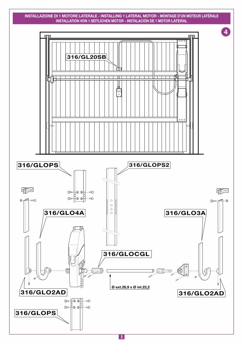
Montaggio laterale1) Una volta individuato il corretto schema di montaggio proce-
dere come indicato al punto 1, 2, 3 e 7 della descrizione di montaggio precedente. In questo caso i supporti motore sono due e vanno fissati uno all’estremità destra ed uno all’estremità sinistra della porta, rispettando la distanza di 65 mm dal carter del contrappeso come indicato in figura.
2) Inserire la boccola dentata del braccio telescopico diretta-mente nell’albero dentato del motoriduttore, portarla in battuta e fissare con il grano in dotazione.
3) Verificare il bilanciamento del telo azionando manualmente la basculante, essa risulterà sbilanciata per effetto del peso dei motoriduttori instal-lati, è pertanto necessario aumentare i contrappesi di 0 kg circa ciascuno.
4) Correggere i contrappesi fintanto che la basculante, alzata in qualsiasi punto, risulterà equilibrata e perfet-tamente in linea.
Installazione laterale
GL20
2-09-2000
dI067 Description :
Product Code :
Date :
Drawing number :
P.J.Heath
CARdIN ELETTRONICA S.p.A - 31020 San Vendemiano (TV) Italy - via Raffaello, 36 Tel: 0438/401818 Fax: 0438/401831
Draft :
All rights reserved. Unauthorised copying or use of the information contained in this document is punishable by law
GL20
65
52 3
70mm
230mm
A
Montaggio base di fissaggio
GL20
20--94
dM0005 Description :
Product Code :
Date :
Drawing number :
P.J.Heath
CARdIN ELETTRONICA S.p.A - 31020 San Vendemiano (TV) Italy - via Raffaello, 36 Tel: 0438/401818 Fax: 0438/401831
Draft :
All rights reserved. Unauthorised copying or use of the information contained in this document is punishable by law
GL20
HB
d
B
E
F
G
C
MN
L
2) Rimontare il motoriduttore sulla base "A", con la lampada di cortesia rivolta verso l’alto, utilizzando le due viti e relativi dadi autobloccanti tolti in precedenza, con l’asse motore nella posizione prescelta.
3) Le squadrette di fissaggio "G" del braccio telescopico possono essere saldate al telaio fisso della basculante, avendo cura di rinforzare la zona di saldatura se la lamiera dovesse risultare d’uno spessore inferiore a 2,5 mm, oppure fissate al telaio fisso o al muro con due bulloni M8 attraverso i fori asolati. Quindi inserire il tubolare "H" tra le squadrette "G" e fissarlo tramite la vite M8 x 25 ed il relativo dado autobloccante in dotazione, ma senza stringere esageratamente in modo da lasciare libertà di rotazione. Per poter funzionare correttamente il tubolare "H" con relativo braccio dritto ha bisogno di muoversi entro uno spazio "minimo", tra il braccio porta "C" ed il carter del contrappeso "L", di almeno 20 mm, se lo spazio fosse inferiore si dovrà passare all’utilizzo di un braccio curvo.
0
2
9

2
Montaggio sblocco a cordino (fig. 6)1) Posizionare la squadretta supporto registro "d" circa 00 mm
sopra la serratura della basculante, in asse con essa, e fissarla con 2 rivetti.
2) Montare la vite di registro "C" con il relativo dado e controdado di bloccaggio (una per motore) lasciando uno spazio per la registrazione.
3) Inserire con cura il bilanciere "G" sulla relativa sede della base "H" in modo che il nasello "F" trascini la leva "L" (fig. 6a) durante la sua rotazione e fissarlo mediante le due viti autofilettanti 4,8x13 "I". Se il montaggio è ben fatto queste ultime possono essere serrate a fondo senza compromettere la libertà di rotazione del bilanciere.
Il bilanciere ha il compito di portare la leva "L" in posizione di sblocco sotto il tiro del cordino "N" (fig. 6b).
4) Montare la molla "M" inserendo il suo gancio "P" nell’occhiello "q" e fissare l’estremità "R" con la vite autofilettante 4,8x13 "O".
5) Infilare il cordino "N" nell’apposito foro ricavato sul bilanciere e quindi infilarlo anche nel corrispondente foro della base "H". Quindi determinare la misura della guaina "E" e infilarvi il cordino. Un po’ d’olio, durante questa fase, oppure un po’ di grasso, aumentano la vita del cordino preservandolo dal-l’usura.
6) Far passare il cordino attraverso la vite di registro "C" e quindi bloccarlo con la vite "B" della serratura "A", dopo averlo teso e avvolto per circa 1/2 giro intorno ad essa. La rondella elastica dentata M8, montata sotto la testa della vite, garantisce un fissaggio sicuro e duraturo del cordino alla serratura.
7) Si ha un corretto funzionamento dello sblocco a cordino quando ad una rotazione di 90° della maniglia della serra-tura "A" corrisponde l’allineamento degli indici "S" (fig. 6b), all’allineamento degli indici corrisponde un fermo meccanico di fine-corsa, per cui il bilanciere non può andare oltre. Per eventuali correzioni del tiro del cordino servirsi della vite di registro "C" che è stata prevista per tale scopo.
8) In alcuni casi la molla "M" potrebbe sviluppare una forza eccessiva non voluta tale da richiamare la maniglia della ser-ratura "A". Se ciò accade non utilizzare la molla "M" in quanto la maniglia deve restare ferma in posizione di sblocco.
Sbloccare dall’esterno (solo sblocco a cordino installato)Ruotare di 90° la maniglia "A", mantenerla in quella posizione e spingere sulla porta in modo da ottenerne l’apertura.Lo sblocco sarà immediato. Infatti, ruotando la maniglia si rende folle l’ingranaggeria del motoriduttore e la porta libera di essere azionata a mano.
Ribloccare dall’esternoPortare la basculante nella posizione desiderata e quindi ruotare la maniglia "A" della serratura verso la posizione di chiusura. Il riaggancio dei denti dell’ingranaggeria all’interno del motoriduttore può non essere immediato, però può essere ottenuto o manualmente spingendo sulla basculante o alla riat-tivazione del motoriduttore.
Sbloccare dall’internoAgire direttamente sulla leva "L" (fig. 6a) fino a raggiungere la posizione di sblocco (fig. 6c), dove resterà agganciata grazie ad un fermo antiritorno.
Ribloccare dall’internoForzare leggermente la leva "L" dalla posizione di sblocco (fig. 6c) in cui si trova per vincere il fermo antiritorno che la mantiene in quella posizione, nel verso opposto a quello di prima. Il ritorno alla posizione bloccato (fig. 6a) avviene automaticamente per effetto di una molla. Il riaggancio dei denti dell’ingranaggeria all’interno del motoriduttore può non essere immediato però può essere ottenuto o manualmente spingendo sulla basculante o alla riattivazione del motoriduttore.
SBLOCCO MANUALE (fig. 6)
PROGRAMMATORE ELETTRONICO
Programmatore per motori in corrente continua con encoder con ricevente incorporata, che permette la memorizzazione di 300 codici utente. La decodifica è di tipo 'rolling code', e la frequenza di funzionamento è di 433 MHz (S449). La velocità di rotazione dei motori è controllata elettronicamente, con partenza lenta e suc-cessivo incremento; la velocità viene ridotta con anticipo rispetto all'arrivo in battuta, in modo da ottenere un arresto controllato. La programmazione, eseguibile mediante un solo pulsante, permette la regolazione del sensore di sforzo e della corsa totale della porta. L'intervento del sensore antischiacciamento/anticonvogliamento causa l'inversione del moto.
• Dopo aver installato il dispositivo, e prima di dare ten-sione alla centralina, verificare che il movimento della porta eseguito in modo manuale (con motore sbloccato) non abbia punti di resistenza particolarmente marcata.• L’uscita per l’alimentazione dei carichi controllati (morsetto 14) è pensata per ridurre il consumo della batteria (se installata) in assenza di tensione di rete; col-legare pertanto le fotocellule ed i dispositivi di sicurezza. • Quando arriva un comando radio (o via filo) il pro-grammatore dà tensione all’uscita CTRL 30 Vdc, e se le sicurezze risultano a riposo attiva il motore.• La connessione all’uscita per i "carichi controllati" per-mette anche di eseguire l’autotest (abilitabile mediante il DIP 5) per la verifica del corretto funzionamento dei dispositivi di sicurezza.• La presenza del sensore di corrente non elimina l’obbligo di installare le fotocellule o altri dispositivi di sicurezza previsti dalle normative vigenti.• Accertarsi, prima di eseguire il collegamento elettrico, che la tensione e la frequenza riportate sulla targhetta caratteristiche corrispondano a quelle dell'impianto di alimentazione. • Tra la centralina di comando e la rete deve essere inter-posto un interruttore onnipolare, con distanza di apertura tra i contatti di almeno 3 mm.• Non utilizzare cavo con conduttori in alluminio; non stagnare l’estremità dei cavi da inserire in morsettiera; utilizzare cavo con marcatura T min 85°C resistente agli agenti atmosferici.• I conduttori dovranno essere adeguatamente fissati in prossimità della morsettiera in modo che tale fissaggio serri sia l’isolamento che il conduttore (è sufficiente una fascetta).
COLLEGAMENTI ALIMENTAZIONE 230 Vac• Portare l'alimentazione generale 230 Vac ai morsetti 1 "L" e 2
"N" e la terra al morsetto 5 controsegnato con il simbolo .
COLLEGAMENTO MOTORI E LUCI dI CORTESIA • M motore 1; M2 motore 2 Il motore "M" e relativa luce di cortesia sono precablati. Per aggiungere un secondo motore senza elettronica a bordo (vedi fig. 8) predisporre una canalina in materiale isolante per il passaggio dei 4 cavi da collegarsi ai morsetti contrassegnati "M2" (filo nero del secondo motore al simbolo -; filo rosso del secondo motore al simbolo +) per il motore ed ai morsetti "9" e "" per la luce di cortesia. La selezione uno o due motori viene effettuata tramite il dIP 3 (vedi pag. 14)
COLLEGAMENTO ENCOdER Yellow Cavo gialloGrey Cavo grigioGreen Cavo verdeBlue Cavo bluAnche l'encoder è precablato, qualora sia necessario scollegarlo (interventi di manutenzione ecc.) è assolutamente necessario rispettare l'ordine dei colori indicato nella scheda.

3
COLLEGAMENTI MORSETTIERA1-2 Alimentazione programmatore 230 Vac3-4 Uscita 230 Vac per trasformatore toroidale5-6 Terra per alimentazione programmatore7-8 Ingresso/Uscita batteria (- e + rispettivamente)9-10 Uscita luce di cortesia (M1 e M2: 24Vdc 5 W )11 Comune per tutti gli ingressi/uscite12 LAMP uscita lampeggiante 24 Vdc 25 W con attivazione
intermittente (50%), 2,5 W con attivazione fissa13 Uscita carichi esterni controllati 30 Vdc (1)
14 Uscita carichi esterni 30 Vdc (1)
15-16 Comune per tutti gli ingressi/uscite17-18 Comune per tutti gli ingressi/uscite19 FTCI (N.C.) ingresso per dispositivi di sicurezza (fotocellula
di inversione in chiusura). L’apertura del contatto, conse-guente all’intervento dei dispositivi di sicurezza, durante la fase di chiusura, attuerà l’inversione del moto
20 TB (N.C.) ingresso pulsante di blocco (all’apertura del contatto si interrompe il ciclo di lavoro fino ad un nuovo comando di moto)
21 Td (N.A.) ingresso pulsante comando sequenziale22 EMRG (N.A.) ingresso pulsante per manovra di emergenza 123 EMRG2 (N.A.) ingresso pulsante per manovra di emergenza 224 Comune per i pulsanti di emergenza25 Massa antenna ricevitore radio26 Centrale antenna ricevitore radio (nel caso si utilizzi un’an-
tenna esterna collegarla con cavo coassiale RG58 imp. 50Ω).Nota (1) La somma delle due uscite per carichi esterni non deve superare 5W.
TUTTI I CONTATTI N.C. NON UTILIZZATI VANNO PONTICEL-LATI e di conseguenza i test sulle sicurezze corrispondenti (TFTC – dIP5) devono essere disabilitati. Se si vuole attivare il test sulla FTCI sia la parte trasmittente che la parte ricevente della fotocellule vanno collegate ai carichi controllati (CTRL 30 Vdc).Si tenga presente che nel caso sia abilitato il test, tra la ricezione del comando e il moto della porta passa circa 1 secondo.
Alimentare il circuito e verificare che lo stato dei led di segnala-zione sia come segue:- L Alimentazione scheda acceso- L2 Errata connessione batteria spento (2)
- L3 Batteria sotto carica spento (3)
- L4 Programmazione codici trasmettitori spento- L5 Segnalazione fotocellule d'inversione "FTCI" acceso (4)
- L6 Segnalazione tasto blocco "TB" acceso (4)
- L7 Segnalazione comando sequenziale (Td/CH) spentoNota (2) Nel caso sia acceso invertire immediatamente la con-
nessione della batteria.Nota (3) Acceso se le batterie sono sotto carica.Nota (4) I LED sono accesi se la relativa sicurezza non è attivata.
Verificare che l'attivazione delle sicurezze porti allo spegnimento del LED ad esse associato. Nel caso in cui il LEd verde di ali-mentazione "L" non si accenda verificare lo stato dei fusibili ed il collegamento del cavo di alimentazione al primario del tra-sformatore. Nel caso in cui uno o più LEd di sicurezza non si accendano verificare che i contatti delle sicurezze non utilizzate siano ponticellate sulla morsettiera.
Collegamenti scheda base
310/GLB424SWS
08-02-2005
DC0391 Description :
Product Code :
Date :
Drawing number :
P.J.Heath
CARDIN ELETTRONICA S.p.A - 31020 San Vendemiano (TV) Italy - via Raffaello, 36 Tel: 0438/401818 Fax: 0438/401831
Draft :
All rights reserved. Unauthorised copying or use of the information contained in this document is punishable by law
Elettronica per basculante(con 6 display a led - selezione a dipswitch )
CS 1226DC039130 V
dc
CM
N
CM
N
TB (N
.C)
LAM
P
CM
N
FTCI (N
.C)
1112131415161718192021
P2 L4
B1 R1
J3
1 2 3 4 5
ON DS1
J2E
MR
G 2
EM
RG
1
L6 L7
L5
D1
COLORE CABLE COLOUR COLORATION KABEL- COLORACIÓN CABLAGGI CODE DES CÂBLAGES FARBEN CABLEADOSYELLOW Giallo Yellow Jaune Gelb Amarillo GREY Grigio Grey Gris Grau Gris GREEN Verde Green Vert Grün Verde BLUE Blu Blue Bleu Blau Azul
Collegamento encoder a 4 fili Connecting 4-wire encoderBranchement encoder à 4 filsAnschluss der Encoder mit 4 DrähtenConexionado encoder con 4 conductores
910
LC 24V
LC 24V
CM
N
TD (N
.O)
TFTC
LP1MO
T
RA
TD
P1
L1
MM
2526 222324
CTR
L 30 Vd
c
CM
N
CM
N
78
BATTERYIN
P3
F2 F10A
F1 F3.15A
F4 F3.15A
F3 T8A
EN
CO
DE
R
M1
M2
J15
63
41
2
L
N230V
230V
TRA
NS
MA
INS
L2
L3
YELLOWGREYGREENBLUE
CS
ER
3
B Buzzer segnalazione modalità "via radio"CSER Connessione seriale (solo per diagnostica)d Display a Led a 6 cifredS Dipswitch di selezioneF Fusibile 3,5A (protezione circuito 24V modalità batteria)F2 Fusibile 0A (protezione motore modalità batteria) F3 Fusibile 8A (protezione alimentazione motore) F4 Fusibile 3,5A (protezione circuito 24V)
J Connessione secondario trasformatoreJ2 Jumper abilitazione alla memorizz. codici Tx via radioJ3 Jumper selezione canale radioMM Modulo di memoria codici TXP Tasto di programmazione (PROG)P2 Tasto di memorizzazione codice TX (MEMO) P3 Tasto di cancellazione codice TX (dEL)R Modulo RF, 433 MHz per trasmettitore S449

4
Impostazione dip-switch dS
ATTENZIONE: se si cambia l'impostazione dei dip, tale impostazione deve essere memorizzata; premere dunque il tasto "PROG", sul display appare la dicitura "dIP" segnalando l’avvenuta memorizzazione.
Comando sequenziale Td/CHDip 1 "ON" = Comando sequenziale "apre-chiude"L’inversione del moto si ha solamente in fase di chiusura.Dip 1 "OFF" = Comando sequenziale "apre-blocco-chiude-blocco"
Richiusura automatica (dIP 2)Dip 2 "ON" = Richiusura automatica abilitataDip 2 "OFF" = Richiusura automatica disabilitata
Funzionamento uno o due motori (dIP 3)Dip 3 "ON" = Funzionamento a un motoreDip 3 "OFF" = Funzionamento a due motori
Uscita lampeggiante (dIP 4)Dip 4 "ON" = Uscita lampeggiante intermittente Dip 4 "OFF" = Uscita lampeggiante fissa
Test su FTCI (dIP 5)Dip 5 "ON" = Test su FTCI abilitatoDip 5 "OFF" = Test su FTCI disabilitato
Se si abilita il test sulle sicurezze bisogna alimentare sia la parte trasmittente che la parte ricevente ai carichi controllati (CTRL 30 Vdc). Con il test abilitato passa circa un secondo dalla ricezione di un comando alla sua effettiva esecuzione.
SENSORE dI CORRENTEIl programmatore esegue il controllo dell’assorbimento del motore, rilevando l’aumento dello sforzo oltre i limiti consentiti nel normale funzionamento ed intervenendo come sicurezza aggiuntiva. Quando il sensore interviene la porta inverte imme-diatamente il moto.
2 3 4 5
ON
2 3 4 5
ON
2 3 4 5
ON
2 3 4 5
ON
2 3 4 5
ON
PROCEdURA dI PROGRAMMAZIONE (Impostazioni del programmatore e del sensore di corrente)
PARTE IL CONTEGGIO DEL TEMPO DI PAUSA (MINIMO 2 SECONdI; MASSIMO 20 SECONdI), SEGNALATO DAL LAMPEGGIO DEL SIMBOLO "PAUSE" SUL DISPLAY.
PREMERE PROG
ATTENZIONE! SE LA PORTA DOVESSE MUOVERSI INCHIUSURA VUOL DIRE CHE LA CONNESSIONE MOTORE NONÈ CORRETTA, PERCIÒ RIPREMERE PROG ANNULLANDO LA PROCEDURA DI PROGRAMMAZIONE,INVERTIRE LA CONNESSIONE MOTORE (CAVO ROSSO-NERO)E RIPETERE LA PROGRAMMAZIONE.
QUANDO LA PORTA ARRIVA ALLA BATTUTA DI APERTURA, INVERTE IL MOTO E DOPO AVER PERCORSO QUALCHE CENTIMETRO RITORNA IN APERTURA PER ACCERTARSI DELLA POSIZIONE DELLA BATTUTA.A QUESTO PUNTO LA PORTA VA IN CHIUSURA. QUANDO ARRIVA IN BATTUTA INVERTE IL MOTO PER QUALCHE CENTIMETRO PER POI RITORNARE IN CHIUSURA, IN MODO DA STABILIRE LA CORRETTA POSIZIONE DELLA BATTUTA DI CHIUSURA.
DOPO AVER EFFETTUATO QUESTE MANOVRE LA LOGICA DI CONTROLLO ESEGUE UNA MANOVRA COMPLETA DI APERTURA E CHIUSURA IN MODO DA TARARE IL SENSORE DI CORRENTE.
A CHIUSURA COMPLETATA IL PROGRAMMATORE SALVA I PARAMETRI ED ESCE DALLA PROGRAMMAZIONE.
L'OPERAZIONE NON È ANDATA A BUON FINE. SARÀ NECESSARIO RIPETERE LA PROGRAMMAZIONE.
PREMERE IL TASTO PROG PER PIÙ DI 4 SECONDI: COMPARE IL SIMBOLO "PAUSE" CHE INDICA LA PROGRAMMAZIONE DEL TEMPO DI PAUSA
...4... sec.
PREMERE PROG
TERMINA IL CONTEGGIO DEL TEMPO DI PAUSA E LA PORTAESEGUE L’APERTURA LENTAMENTE, IN MODO DATROVARE LO STATO DI COMPLETAMENTE APERTO
• È obbligatoria la presenza delle battute di apertura e chiusura.• Accertarsi che le sicurezze siano a riposo: in caso contrario non si entra in programmazione.

5
Sul display si accendono i segmenti relativi allo stato dei comandi (LED acceso = comando attivo) e delle sicurezze (LED acceso = sicurezza a riposo.
Il numero di manovre appare sul display: tale numero rimane sempre visualizzato, finchè non si sceglie di cambiare l’impostazione. Al superamento del numero 999999 la cifra dei milioni è fornita dal numero di punti decimali accesi.
Nella modalità "test" (attivabile solo con sistema fermo) è possibile eseguire verifiche sullo stato dei comandi e sicurezze, ed effettuare eventuali manutenzioni. Il lampeggiante si attiva una volta ad ogni comando ("Td-TB-FTCI") ricevuto. In questa modalità è possibile, utilizzando l'apposito programmatore esterno, collegato via cavo al connettore CSER (fig.13), attivare la comunicazione seriale. Durante la comunicazione sul display appare una riga tratteggiata; dopo 5 secondi di inattività si ritorna alla modalità di "test".Per tornare al normale funzionamento premere "PROG", facendo apparire la scritta "test", e attendere 10 secondi.
PREMERE PROG
Memorizzazione della configurazione a DIP-SWITCH e visualizzazione della versione di firmware (es. “0”)
PREMERE PROG
PREMERE PROG
0 sec
Attivando gli ingressi ("Td - TB - FTCI") si aziona il lampeggiante e la luce di cortesia.PREMERE PROG
Lo stato delle sicurezze TB, FTCI è sempre rappresentato sul display.
0 sec
PREMERE PROG
Collegare il dispositivodi programmazione (CSER) e attivarlo
5 sec
0 sec
Impostazione del sensore di corrente.1 = assorbimento del motore + 1 ampère 2 = assorbimento del motore + 2 ampère 3 = assorbimento del motore + 3 ampère
PREMERE PROG
Ad ogni pressione del tasto "PROG" viene incrementato il numero (da 1 a 3).
Dopo 10 secondi dall'ultima modifica si uscirà automaticamente salvando il valore selezionato (es. 3)
PREMERE PROG
0 sec
0 sec
MENU dI VISUALIZZAZIONE
Agendo sul tasto PROG si accede in sequenza alle seguenti funzioni:- memorizzazione dello stato dei dip-switch;- visualizzazione dello stato dei comandi e delle sicurezze;- visualizzazione del numero di manovre;- ingresso in modalità "test";- impostazione del livello sensore di corrente.
Riposizionamento automaticoSe si dovesse verificare un blocco del programmatore dovuto ad un’anomalia del conteggio encoder , ad un reset del pro-grammatore , allo sblocco del motore o ad un problema con il motore il lampeggiante e la luce di cortesia si attivano contemporaneamente per 2 secondi e poi rimangono spenti per 0 secondi. Alla ricezione di un comando il programmatore, dopo un prelampeggio di 10 secondi, muove automaticamente
la porta, a bassa velocità, fino alla battuta di chiusura (per 2 volte come nella procedura di programmazione) in modo da recupe-rare la posizione. A questo punto il programmatore riprende il normale funzionamento. Durante la fase di riposizionamento non viene accettato nessun comando, mentre le sicurezze agiscono bloccando il moto solamente finché risultano in allarme.• Per interrompere la fase di riposizionamento premere il tasto
"PROG" o "TB".
6
C. Cancellazione completa della memoria utenti (pag. 8,9):1) Tenere premuti entrambi i pulsanti ("P2+P3") per più di 4 sec.2) Il LED "L4" rimane acceso per tutto il tempo della cancellazione
(8 sec. circa).3) Il LED "L4" si spegne: la cancellazione è stata completata.Nota: Quando la memoria del ricevitore è prossima al completamento, la ricerca dell’utente può durare un massimo di 1 secondo da quando è stato ricevuto il comando radio. Se il Led "L4" è sempre acceso, la memoria è interamente occupata: per memorizzare un nuovo TX sarà necessario cancellare un codice dalla memoria.
d. Memorizzazione di ulteriori canali via radio • La memorizzazione può essere anche attivata via radio (senza
aprire la scatola dove è alloggiata la centralina) se il jumper "J2" (pag. 8,9) è inserito.
1) Assicurarsi che il jumper "J2" sia inserito (pagine 8, 9).2) Utilizzando un radiocomando, in cui
almeno uno dei tasti di canale "A-B-C-d" sia già stato memorizzato nel ricevitore, attivare il tasto all’interno del radiocomando come indicato nella figura.
Nota: Tutti i ricevitori raggiungibili dall'emissione del radiocomando, e che abbiano almeno un canale del trasmetti-tore memorizzato, attiveranno contemporaneamente il buzzer di segnalazione "B" (pag. 8-9).3) Per selezionare il ricevitore in cui memorizzare il nuovo codice
attivare uno dei tasti di canale dello stesso trasmettitore. I ricevitori che non contengono il codice di tale tasto si disatti-veranno, con l'emissione di un "bip" lungo 5 secondi; quello invece che contiene il codice emetterà un altro "bip" che dura un secondo, entrando effettivamente nella modalità di memorizzazione "via radio".
4) Premere il tasto di canale precedentemente scelto sul tra-smettitore da memorizzare; ad avvenuta memorizzazione il ricevitore emetterà 2 "bip" di mezzo secondo, dopodiché il ricevitore sarà pronto a memorizzare un altro codice.
5) Per uscire dalla modalità lasciare trascorrere 3 sec. senza memorizzare codici. Il ricevitore emetterà un "bip" lungo 5 sec. ed uscirà dalla modalità.
Nota: Quando la memoria viene completamente occupata, il buzzer emetterà 10 "bip" ravvicinati, uscendo automaticamente dalla modalità di memorizzazione "via radio", ed il LED "L4" rimane acceso; la stessa segnalazione si ottiene anche ad ogni tentativo di entrare in modalità "via radio" con memoria intera-mente occupata.
COLLEGAMENTO ANTENNA Utilizzare l’antenna accordata ANS400/ANS800-, da collegare al ricevitore mediante cavetto coassiale RG58 (impedenza 50Ω) di lunghezza max. 5 m.
) AutomaticaSi seleziona abilitando la richiusura automatica (dip "2" in posizione "ON"). Partendo dalla condizione di completamente chiuso, il comando sequenziale inizia un ciclo completo di funzionamento, che terminerà con la richiusura automatica. La richiusura auto-matica entra in funzione con un ritardo pari al tempo di pausa programmato, a partire dal termine della manovra di apertura oppure dall'istante in cui sono intervenute le fotocellule per l'ul-tima volta durante il tempo di pausa (l'intervento delle fotocellule causa un reset del tempo di pausa). Durante il tempo di pausa, sul display lampeggia il simbolo . La pressione del tasto di blocco durante il tempo di pausa impedisce la richiusura automatica con conseguente blocco del lampeggio sul display.Nota: la luce di cortesia si accende ad ogni comando di movi-mento impartito al sistema, sia via filo che via radio, e si spegne dopo 30 secondi dal termine della manovra.
È possibile azionare a distanza l'automazione tramite radio-comando; per configurare le due funzioni sui canali A-B-C-d si utilizzano i jumper di selezione "J3":- posizione "" = funzione 1, COMANdO SEqUENZIALE;- posizione "2" = funzione 2, COMANdO dI BLOCCO. Il comando sequenziale è configurabile (dip "") in "apre-blocco-chiude-blocco" oppure "apre-chiude".
Modulo di memoria (MM)Estraibile, costituito da una memoria non volatile di tipo EEPROM, contiene i codici dei trasmettitori e permette la memorizzazione di 300 codici. Nel modulo di memoria i codici vengono mantenuti anche in assenza di alimentazione.
Prima di procedere alla prima memorizzazione, ricor-darsi di cancellare interamente la memoria. Dovendo sostituire la scheda elettronica per guasto, il modulo di memoria può essere estratto da essa ed inserito nella nuova scheda curandone l’orientamento come indicato in figura a pagina 8, 9.
Segnalazioni LEd "L4" (pag. 8,9): lampeggio veloce: cancellazione singolo codicelampeggio lento: memorizzazione di un codicesempre acceso: memoria interamente occupata.
GESTIONE dEI COdICI dEI TRASMETTITORIA. Memorizzazione di un canale (tramite il Tx associato)B. Cancellazione di un canale (tramite il Tx associato)C. Cancellazione completa della memoria codicid. Memorizzazione di ulteriori canali via radio (senza aprire
il contenitore dove è alloggiata la centralina)
A. Memorizzazione di un canale (pag. 8,9):1) Premere il pulsante "P2" MEMO e tenerlo premuto: il LED "L4"
lampeggia lentamente. 2) Attivare contemporaneamente il trasmettitore sul canale da
memorizzare.3) Tenere premuto "P2" MEMO fino a che il LED "L4" riprende
a lampeggiare.4) Rilasciare il tasto "P2" MEMO: il LED continua a lampeggiare.5) Attivare una seconda volta il trasmettitore (stesso trasmettitore,
stesso canale; se il canale è diverso oppure si tratta di un altro trasmettitore la memorizzazione termina senza successo).
6) Fine della memorizzazione: il LED "L4" rimane acceso per 2 secondi, segnalando la corretta memorizzazione.
Nota: Non è possibile memorizzare un codice che sia già in memoria: in un caso simile durante l’attivazione del radiocomando (punto 2) si interrompe il lampeggio del LED. Solo dopo il rilascio del pulsante "P2" MEMO sarà possibile riprendere la procedura di memorizzazione. Se dopo la prima attivazione del radiocomando non lo si attiva per la seconda volta, dopo 15 secondi si esce automaticamente dalla modalità di memorizzazione senza memo-rizzare il nuovo codice utente.
B. Cancellazione di un canale (pag. 8,9):1) Premere "P3" dEL e tenerlo premuto: il LED "L4" lampeggia
velocemente.2) Attivare il trasmettitore sul canale da cancellare.3) Il LED rimane acceso per 2 secondi, segnalando l’avvenuta
cancellazione.Nota: Se l’utente che si vuole cancellare non è in memoria, il LED smette di lampeggiare; sarà possibile riprendere la procedura di cancellazione solo dopo il rilascio del pulsante "P3". Sia per la procedura di memorizzazione che per quella di cancellazione, se si rilascia il tasto prima dell’attivazione del radiocomando si esce subito dalla modalità.
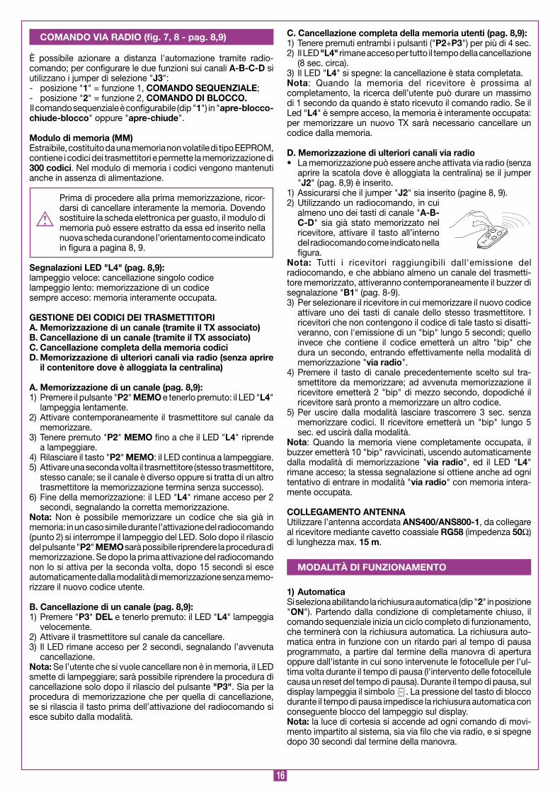
COMANdO VIA RAdIO (fig. 7, 8 - pag. 8,9)
MEMORIZZAZIONE CODICE TX-RX
RCQ449100
13-04-2001
DM0531 Description :
Product Code :
Date :
Drawing number :
P.J.Heath
CARDIN ELETTRONICA S.p.A - 31020 San Vendemiano (TV) Italy - via Raffaello, 36 Tel: 0438/401818 Fax: 0438/401831
Draft :
All rights reserved. Unauthorised copying or use of the information contained in this document is punishable by law
MR
MOdALITà dI FUNZIONAMENTO

7
• Il tempo di carica con batterie efficienti può arrivare ad un massimo di 15 ore: se il tempo richiesto è maggiore, valutare la sostituzione; si consiglia comunque, per avere il massimo delle prestazioni, di sostituire le batterie ogni tre anni.
Quando le batterie si scaricano completamente (in assenza di tensione di rete) il programmatore perde la posizione della porta e quindi, al ripristino dell'ali-mentazione di rete (al primo comando impartito) viene eseguita la procedura di riposizionamento automatico (vedi pag. 15). Evitare di lasciare il programmatore disalimentato per periodi prolungati (oltre 2 giorni).
• In modalità batteria non è possibile entrare in programmazione.
LEd di segnalazione (vedi pag. 8, 9)L2: in assenza di tensione di rete, risulta acceso quando la batteria
non è collegata correttamente; L3: acceso quando la corrente erogata dal circuito di carica-bat-
terie è superiore alla corrente di mantenimento della batteria (50 mA circa).
I fili per la connessione della batteria al circuito di carica non devono essere mai messi in corto circuito, pena il danneggiamento delle batterie e, nel caso peggiore, il rischio di ustioni (se il contatto viene fatto con parti metalliche che toccano la pelle). Collegarli esclusiva-mente ai morsetti dedicati (7, 8) rispettando le polarità. Se le batterie vengono rotte si può avere fuoriuscita di acido. Le batterie devono essere installate e tolte da personale qualificato. Le batterie esauste non devono essere gettate nei rifiuti urbani ma smaltite secondo le norme vigenti.
Verifica delle batterieCon la porta in posizione di completa chiusura: il display deve risultare spento:Verificare che il led "L3" (batterie sotto carica) sia spento.Togliere l'alimentazione di rete, verificando che sul display appaia il simbolo . Dare un comando di moto, e misurare la tensione com-plessiva delle due batterie che dovrà essere di almeno 22 Vdc.
2) Semi-automaticaSi seleziona disabilitando la richiusura automatica (dip " 2" in posizione "OFF"). Il ciclo di lavoro è gestito con comandi separati di apertura e chiusura. Arrivato in posizione di completa apertura il sistema attende un comando di chiusura via radio o tramite tasto per completare il ciclo. La lampada spia rimane accesa quando il portone non è completamente chiuso.
3) Manovra manuale con motore sbloccatoSbloccando i motori la porta può essere spostata a mano; in questa fase il programmatore non controlla la posizione della porta e quindi al successivo comando di movimento (dopo aver ribloccato i motori) la porta potrá, a seconda della necessitá, eseguire l’autoriposizionamento perché si rileva un errore di posizione.
Attenzione! Se viene dato un comando con il motore sbloccato sul display comparirà il simbolo .
4) Manovra di emergenzaNel caso in cui il programmatore elettronico non dovesse più rispondere ai comandi per un malfunzionamento, agire sugli ingressi EMRG o EMRG2 per muovere la porta in modalità uomo presente. Gli ingressi EMRG ed EMRG2 agiscono direttamente sul controllo del motore, escludendo la logica.Il movimento della porta verrà effettuato a velocità di regime e la direzione del moto è la seguente:Comando EMRG: chiude Comando EMRG2: apre
Attenzione! Durante la manovra di emergenza tutte le sicurezze risultano disabilitate e non c'è controllo sulla posizione della porta: rilasciare dunque i comandi prima dell'arrivo in battuta. Usare la manovra di emergenza soltanto in condizioni di estrema necessità.
Dopo aver effettuato una manovra di emergenza il programmatore elettronico "perde" la posizione della porta ( sul display) e quindi al ripristino del normale funzionamento verrà effettuato il riposizionamento automatico (vedere pag. 15).
Il dispositivo permette il funzionamento dei dispositivi collegati alla centralina anche in assenza di rete. • Per indicare il funzionamento a batteria, quando la porta è
completamente chiusa, sul display compare un trattino che scorre lungo il "perimetro esterno". Se le batterie si scaricassero fino alla soglia di guardia, sul display si avrebbe ugualmente un trattino in movimento . Quando poi la batteria si scarica troppo apparirà e si avrà il blocco completo del programmatore.
• Quando la porta è completamente chiusa, i carichi esterni controllati (CTRL 30 Vdc) non sono alimentati, per aumentare l’autonomia delle batterie; quando viene inviato un comando (via filo o via radio) il programmatore prima di tutto alimenta i carichi e valuta lo stato delle sicurezze. Ne consegue che l’ese-cuzione del comando, qualora consentita (sicurezze a riposo) verrà ritardata per il tempo necessario alla ripresa del corretto funzionamento dei dispositivi stessi (circa 1 secondo). Se dopo tale intervallo di tempo si rileva una sicurezza in allarme, il comando non viene eseguito e l’alimentazione ai carichi esterni viene automaticamente tolta: il programmatore torna in stato di stand-by.
Nota: per quanto detto sopra, se si desidera utilizzare un ricevitore esterno, lo si dovrà alimentare collegandolo al morsetto 13 (pag. 8, 9): soltanto così, infatti, sarà possibile che il comando via radio riesca ad attivare la porta.
• L'autonomia del sistema quando è alimentato a batteria è stret-tamente legata alle condizioni ambientali, ed al carico connesso al morsetto 13 (pag. 8, 9) della centralina (che anche in caso di blackout alimenta i circuiti ad esso collegati).
FUNZIONAMENTO A BATTERIA (OPZIONALE)

8
Visualizzazione all’accensione
Visualizzato per due secondi:"GLB242" = modello della centralina
segnala la memorizzazione della configurazione dei dip-switch e la versione del firmware.
Segnalazioni di allarme
Sistema non programmato
È necessario entrare in modalità di programmazione per pro-grammare il sistema.
Fuori posizione
Nel caso di installazione, è necessario entrare in programmazione per programmare la corsa della porta.Nel funzionamento normale invece segnala che alla ricezione d'un comando dará inizio, dopo un prelampeggio di 10 sec., al riposizionamento automatico.
Blocco durante la programmazione encoder
Si verifica quando viene attivato un contatto N.C. (TB, FTCI) durante la programmazione encoder o riposizionamento auto-matico. Una volta ristabilito lo stato passivo delle sicurezze la porta riprende il moto automaticamente. Si verifica anche quando viene a mancare la tensione di rete durante la fase di programmazione.
Errore nel test delle sicurezze
Occorre controllare lo stato delle sicurezze, verificando che vadano in allarme (LED relativo spento) quando un ostacolo si trova in mezzo al loro raggio di azione. Se si riscontra un’ano-malia sostituire la sicurezza guasta oppure in sua assenza ponticellare l’ingresso relativo e disabilitare il test relativo alla sicurezza stessa (dip 5).
Problema sull'alimentazione del motore
Si verifica quando il programmatore dà un comando al motore, ma il motore non si mette in moto. È sufficiente controllare le connessioni relative al motore e lo stato dei fusibili "F2" ed "F3". Dopodiché riprovare a dare un comando: verrà eseguito il riposizionamento (pag. 15); se il motore non si dovesse rimettere in moto, allora ci potrebbe essere un problema meccanico al motore o un problema sulla centralina.
Motore sbloccato
Si verifica quando si dà un comando di movimento ed il motore è sbloccato. Bloccare il motore (vedere le istruzioni relative al blocco e sblocco) e dare un comando: verrà eseguita la proce-dura di riposizionamento (pag. 15).
Errore encoder
Se si verifica significa che c'è un problema sui segnali relativi all’encoder; verificare le connessioni relative ed eseguire il riposizionamento automatico (pag. 15).
Errore del sensore di corrente
Con il motore fermo questo simbolo indica che c'è un problema sul sensore di corrente.
Segnalazioni di funzionamento
Programmazione del tempo di pausa
Programmazione automatica in corso
Comunicazione seriale (CSER) attivata(solo per diagnostica)
Fase di apertura
Blocco
Pausa per la richiusura automatica(solo se abilitata)
Fase di chiusura
Aggiornamento del sensore di corrente
Apertura + compensazione sensore
Chiusura + compensazione sensore
Modalità di test
Modalità batteria con batteria carica
Modalità batteria con batteria poco carica
Blocco per batteria scarica
INdICAZIONI dEL dISPLAY (d, pagine 3)
9
• These instructions are aimed at professionally qualified "INSTALLERS OF ELECTRICAL EqUIPMENT" and must respect the local standards and regulations in force. All materi-als used must be approved and must suit the environment in which the installation is situated.
• All maintenance operations must be carried out by profession-ally qualified technicians. Before carrying out any cleaning or maintenance operations make sure the power is disconnected at the mains.
• This appliance must be used exclusively for the purpose for which it has been made. "i.e. The automation of garage doors" Any non authorised modifications are to be considered improper and therefore dangerous.
USEThe appliance may be used to operate a single or articulated garage door. For garage doors with a width of over 4 m and not more than 2,7 m in height and for garage doors with a pedestrian access door two motors are required (one motor with on board electronics 30/GLB242SWS and one without 30/GLB240SWS).
The manufacturer accepts no liability for situations arising from an electrical installation which does not conform to the local standards and regulations in force.
It is the responsibility of the installer to make sure that the fol-lowing public safety conditions are satisfied:1) The pedestrian door must not open on its own, e.g.; swing
open while the garage door is in movement2) The appliance must not be operated when the pedestrian door
is not fully closed.3) Make sure that there are no dangerous sharp edges (R=3mm min.)4) Make sure that the end-user is aware that children and/or pets
must not be allowed to play within the area of a garage door installation. If possible include this in the warning signs.
5) A correct earth connection is fundamental in order to guarantee the electrical safety of the machine
6) If you have any questions about the safety of the door operat-ing system, do not install the operator. Contact your dealer for assistance.
TECHNICAL dESCRIPTION• Single piece geared reduction unit with an incorporated
encoder.• 28 V direct current drive motor.• Permanently lubricated double reduction unit mounted on a
cast iron stator with a never ending screw.• Irreversible reduction unit with a key-operated manual release
mechanism.• 30/GLB242SWS Motor with an incorporated electronic
programmer complete with power stage, logic control, battery charger and radio receiver. Power is rooted to the card by a separate toroidal transformer housed in the same container and connected to the card
• 30/GLB240SWS motor without on board electronics• Base in zinc-plated steel • Carter in shock-proof plastic• Courtesy light
ACCESSORIES36/GLO2Ad - Straight telescopic arm length 700 mm.36/GLO3A - Curved (right) telescopic arm length 700 mm.36/GLO4A - Curved (left) telescopic arm length 700 mm.36/GLO6A - Straight telescopic arm length 1000 mm.36/GLOPS - Motor support extension.36/GLOTG - Pair of pipes, pipe support brackets and DIN
threaded pins for central motor positioning.36/GLOCGL - Ferrule and DIN threaded pin, with pipe support
brackets for lateral motor positioning.36/GL20SB - Manual release cord.
During the opening/closing manoeuvre check for correct opera-tion and activate the emergency stop button in case of danger.The appliance must not be activated in the dark therefore make sure that the night lights function correctly.The appliance can be manually released in case of emergency (see manual release mechanism on page 21).Periodically check the moving parts for wear and tear and grease if required, using lubricants which maintain their friction levels unaltered throughout time and are suitable for temperatures of -20 to +70°C. In case of failure or operational anomalies switch off the power at the mains do not attempt to repair the appliance yourself. Periodically check the correct operation of all safety devices (photoelectric cells etc.).Eventual repair work must be carried out by specialised person-nel using original spare parts. The appliance is not suitable for continuous operation and must be contained within the value stipulated (see technical data on page 56).
The minimum controls which may be installed are SEQUEN-TIAL-STOP, these controls must be installed in a location not accessible to children.
Before starting with the installation of the system check that the structure which is to be automated is in good working order and respects the local standards and regulations in force. Automating an existing system which has sliding or balancing problems will not solve those problems and may even make them worse by placing more stress on weakened or damaged areas. To this end make sure that the runner guides slide freely and grease all the moving parts (pins, castors etc.) using lubricants which maintain unaltered friction characteristics over a period of time and are suitable for temperatures of -20 to +70°C.
TO REdUCE THE RISK OF SEVERE INJURY OR dEATH REAd THE FOLLOWING REMARKS CAREFULLY BEFORE PROCEEdING WITH THE INSTALLATION. PAY PARTICULAR ATTENTION TO ALL THE PARAGRAPHS MARKEd WITH THE SYMBOL . NOT REAdING THESE IMPORTANT INSTRUCTIONS COULd COMPROMISE THE COR-RECT WORKING ORdER OF THE SYSTEM.
IMPORTANT REMARKS IMPORTANT REMARKS IMPORTANT REMARKS
IMPORTANT SAFETY INSTRUCTIONS
USER INSTRUCTIONS
INSTALLATION INSTRUCTIONS

20
Sezione basculante
GL20
3--2000
dM058 Description :
Product Code :
Date :
Drawing number :
P.J.Heath
CARdIN ELETTRONICA S.p.A - 31020 San Vendemiano (TV) Italy - via Raffaello, 36 Tel: 0438/401818 Fax: 0438/401831
Draft :
All rights reserved. Unauthorised copying or use of the information contained in this document is punishable by law
GL20
x
Y
q
P
FITTING THE UNITFitting the motor centrally1) Remove the motor from its positioning base "A" fasten the
two motor base extensions "B" to the positioning base. Mark the position of the motor axis on the positioning base "A" and fasten the complete profile "A" and "B" to the cross piece of the garage door. The motor axis must be 70 mm below the hinged point of the door arm "C". (for non flush fitting garage doors) or half way up for flush fitting garage doors (see figs 2-3). The motor support, complete with its extensions, must be fitted to the side of the lock and has to cover at least three cross pieces "d", "E" and "F" using a minimum of three Ø 5 mm rivets for each cross piece.
2) Fasten the geared motor (axis in the chosen position) to the support base "A", with the night light facing towards the top, using the two previously removed screws and lock nuts.
3) The telescopic arm fastening brackets "G" can either be welded to the fixed frame of the garage door (reinforce the welding area if the metal sheet is less than 2,5 mm thick) or fixed to the frame/wall using two M8 bolts.
At this point slide the tube "H" between the arms of the bracket "G" and fasten down (don’t over tighten) using the supplied M8 x 25 screws and lock nuts.
To guarantee correct operation the tube "H" with its straight arm inserted must be able to move within a minimum space of 20 mm between the door arm "C" and the counterweight housing "L". If the available space is inferior you will have to use a curved arm.
4) Place the tube "H" (with the arm "R" inserted) parallel to the counterweight housing "L" and measure the distance "W" between the end of the motor shaft "S" and the internal part of the straight arm "O" as shown in figure 10. Subtracting 63 mm from the distance "W" will give you the overall length of the motor shaft extension tube (fig. 2,3). Follow the same pro-cedure to measure the cutting length for the other extension tube. Remember to file down the sharp edges after cutting.
5) Position the support brackets "M" (fig.9) at the same height as the geared motor axis and drill two Ø4 mm holes with which to fix the bracket to the garage door framework.
6) Assemble the 36/GLOTG group (fig.2-3) motor shaft extension tubes, threaded joints and relative sup-ports and then fasten down the support tubes using the supplied 4,8 x 6 self-tapping screws.
7) Measure the distance between the motor axis "P" and the axis of the telescopic arm hinge hole "q" with the garage closed "x" and with the garage door open "Y".
Cut the tube "H" and straight arm "R" to the minimum measured size (minus a play of 2 cm). Remember to file down the sharp edges after cutting. Reassemble and fasten down the arms using the supplied M8 grub screws.
8) Drill the extension tube as follows:- Make sure that the garage door is closed and the geared motor
is free;- Using a Ø0 mm drill bit make a hole in the centre of the joint
"N" (fig.2-3) which passes half way through the tube.- Insert the Ø0x50 elastic pin halfway through the tube.- Open the garage door and drill the joint from the other side
then allow the elastic pin to outcrop the same distance on both sides of the joint.
9) Check that the door is well balanced by manoeuvring it manu-ally. The weight of the motor means you will have to increase the counter weights by 4-5 kg on each side.
Compensate the counter weights until the garage door is perfectly balanced.
Fitting the motor laterally1) Once you have decided upon the correct assembly diagram
follow points 1,2,3 and 7 of the previous paragraph. In this case there are two motor supports and they should be fixed to the extreme right and left of the garage door maintaining a distance of 65 mm from the counterweight housing as shown in the drawing.
2) Insert the threaded joint of the telescopic arm directly into the threaded shaft of the motor, push it well in, and fasten down using the supplied grub screw.
3) Check that the door is well balanced by manoeuvring it manually. The weight of the motor means you will have to increase the counter weights by about 0 kg on each side.
4) Compensate the counter weights until the garage door is perfectly balanced.
Installazione laterale
GL20
2-09-2000
dI067 Description :
Product Code :
Date :
Drawing number :
P.J.Heath
CARdIN ELETTRONICA S.p.A - 31020 San Vendemiano (TV) Italy - via Raffaello, 36 Tel: 0438/401818 Fax: 0438/401831
Draft :
All rights reserved. Unauthorised copying or use of the information contained in this document is punishable by law
GL20
65
52 3
9
70mm
230mm
A
Montaggio base di fissaggio
GL20
20--94
dM0005 Description :
Product Code :
Date :
Drawing number :
P.J.Heath
CARdIN ELETTRONICA S.p.A - 31020 San Vendemiano (TV) Italy - via Raffaello, 36 Tel: 0438/401818 Fax: 0438/401831
Draft :
All rights reserved. Unauthorised copying or use of the information contained in this document is punishable by law
GL20
HB
d
B
E
F
G
C
MN
L
Montaggio tubi
GL20
20--2000
dM057 Description :
Product Code :
Date :
Drawing number :
P.J.Heath
CARdIN ELETTRONICA S.p.A - 31020 San Vendemiano (TV) Italy - via Raffaello, 36 Tel: 0438/401818 Fax: 0438/401831
Draft :
All rights reserved. Unauthorised copying or use of the information contained in this document is punishable by law
GL20
20
H
W
S
C
H
O
R
L
0
2

2
Fitting the manual release cord (fig. 6)1) Position the setting support bracket "d" about 00 mm above
the garage door lock (in line with it) and fasten down using 2 rivets.2) Mount the setting screw "C" with its relative nut and lock
nut (one for each motor) and leave a space in order to allow adjustment later.
3) Carefully insert the spring mechanism "G" into its seat on the base "H" so that the tab "F" moves the lever "L" (fig.6a) while it rotates and then fasten down using the two 4,8 x 13 self-tapping screws "I".
If the unit has been correctly assembled you will be able to tighten down the two screws without them interfering with the rotation of the spring mechanism.
The spring mechanism moves the lever "L" into the release position when the cord "N" (fig. 6b) is pulled.
4) Mount the spring "M" by inserting its hook "P" into the open-ing "q" (fig. 6b) and fasten the other end "R" using the 4,8 x 13 self-tapping screws "O".
5) Insert the cord "N" through the hole on the spring mechanism and then into the corresponding hole on the base "H". Work out the required length of the sheath "E" and insert the cord. Use a little oil or grease to extend the lifetime of the cord.
6) Pass the cord through the setting screw "C" and fasten down using the screw "B" of the lock "A" after having tightened the cord and having wound half a turn around the screw.
The M8 serrated washer placed below the screw will fasten the cord into position.
7) The manual release mechanism is working correctly when a 90° rotation of the door handle corresponds to the alignment of the marker tab "S" (fig. 6b). The spring mechanism cannot go past this mechanical stop. Use the setting screw "C" if any ulterior adjustments are required.
8) In certain cases the spring "M" could develop too much force and pull back the handle of the lock "A". If this occurs you may remove the spring "M" (it is not always required) the handle will now remain in the released position.
Releasing the mechanism externally(only with a release cable installed)Rotate the handle "A" through 90°. Hold it in this position and press on the door to open it. The release mechanism works imme-diately. Rotating the handle frees the reduction motor gears.
Locking the mechanism externally Move the door to the desired position and rotate the handle "A" towards the closed position. The reduction motor gears may not lock immediately but it can be locked manually by pressing on the door or by reactivating the motor.
Releasing the mechanism internallyOperate the lever "L" (fig. 6a) until it reaches the release posi-tion (fig. 6c) where it will remain thanks to an anti return mecha-nism.
Locking the mechanism internallyLightly press, in the opposite direction, on the lever "L" (fig.6a) to overcome the anti-return mechanism. The presence of the spring will make the mechanism automatically return to the blocked position (fig. 6a). The reduction motor gears may not lock immediately but they can be locked manually by pressing on the door or by reactivating the motor.
Electronic control unit for dc motors with an incorporated encoder and radio receiver card, which allows the memorisation of 300 user codes. The “rolling code” type decoder uses 433.92 MHz (S449) transmitters.The motor rotation speed is electronically controlled, starting slowly and increasing in speed; the speed is reduced as it nears the travel limit so as to enable a controlled smooth stop.Programming is carried out using one button and allows you to set the system, the current sensor and the entire door travel distance. The intervention of the anticrush/antidrag sensor during the closing and opening stages causes travel direction inversion.
• After having installed the device, and before powering up the programmer, release the door (manual release mechanism) and move it manually, checking that it moves smoothly and has no unusual points of resistance.• The controlled load output (binding post 14) is aimed at reducing battery power consumption (if they are installed) during blackouts; photocells and other safety devices should be connected to this output. • When a command is received, via radio or via wire, the electronic programmer routes voltage to the CTRL 30 Vdc output. It then evaluates the state of the safety devices and if they are at rest it will activate the motor.• Connecting devices to the controlled output contact also allows you to carry out the autotest function (enabled using DIP 5) and check that the safety devices are functioning correctly.• The presence of the electrical current sensor does not dis-pense with the obligation to install photoelectric cells and other safety devices foreseen by the safety standards in force.• Before connecting the appliance make sure that the voltage and frequency rated on the data plate conform to those of the mains supply. • An all pole trip switch with at least 3 mm between the contacts must be installed between the unit and the mains supply.• Don't use cables with aluminium conductors; don't solder the ends of cables which are to be inserted into the binding posts; use cables marked T min 85°C and resistant to atmospheric agents.• The terminal wires must be positioned in such a way that both the wire and the insulating sheath are tightly fastened (a plastic jubilee clip is sufficient).
ELECTRICAL CONNECTION 230 Vac• Run the 230 Vac power cable to binding posts 1 “L” and 2 “N” and
attach the earth wire to binding post 5 marked with the symbol .
MOTORS ANd COURTESY LIGHT CONNECTION • M motor 1; M2 motor 2 The motor “M” and its relative courtesy light are pre-wired. To add a second motor without on board electronics (see fig. 8) run a channel made of isolating material containing the four wires that are to be connected to the binding posts indicated by the word “M2” (the black wire from the second motor to the symbol -; the red wire from the second motor to the symbol +) for the motor and to binding posts “9” and “” for the courtesy light.Selecting one or two motors is carried out using dip 3 (see page 23)
ENCOdER CONNECTION Yellow Yellow cable Grey Grey cable Green Green cableBlue Blue cableThe encoder is also pre-wired. If you need to disconnect the encoder (for maintenance interventions etc.) you must replace the cable fol-lowing the colour order of the wires as shown on the card.
MANUAL RELEASE MECHANISM (fig. 6)
ELECTRONIC PROGRAMMER

22
TERMINAL BOARd CONNECTIONS1-2 Control unit power supply 230 Vac3-4 230 Vac output for the toroidal transformer5-6 Control unit power supply earth wires7-8 Battery input/output (- and + respectively)9-10 Courtesy light output (motor 1 and 2: 24Vdc 5 W)11 Common for all inputs and outputs12 LAMP 24Vdc 25W output for warning lights, intermittent
activation (50%), 2,5W continuous activation13 Controlled output, powering external loads 30 Vdc (1)
14 Output powering external loads 30 Vdc (1)
15-16 Common for all inputs and outputs17-18 Common for all inputs and outputs19 FTCI (NC contact) Safety and control devices in input
(photocells invert the travel direction when an obstruction is detected). Opening this contact will provoke a travel direction inversion during closure due to the cutting in of the safety device.
20 TB (NC contact) Stop button input (The opening of this contact interrupts the cycle until a new movement command is given)
21 Td (NO contact) sequential command button input22 EMRG (NO contact) emergency manoeuvre input 123 EMRG2 (NO contact) emergency manoeuvre input 224 Common for the emergency buttons25 Outer conductor for radio receiver antenna26 Inner conductor for radio receiver antenna (if an external
antenna is fitted use a coaxial type cable RG58 with an impedance of 50Ω).
Note (1) The total of the 2 external device outputs must not exceed 5W.
ALL UNUSEd NC CONTACTS MUST BE BRIdGEd and conse-quently the security device test must also be deactivated (TFTC – dIP 5). If you want to activate the FTCI test both the transmis-sion and receiver parts of the photocell must be connected to the binding post marked “CTRL 30 Vdc”. If the test is active there will be a 1 second delay between the command transmission and movement of the door.
Switch on the power and make sure that the indicator LEDS are in the following condition:- L Power on lit- L2 Wrong battery connection off (2)
- L3 Battery charging off (3)
- L4 Indicates transmitter code programming off- L5 Indicates active inverting photocells "FTCI" lit (4)
- L6 Indicates active blocking button "TB" lit (4)
- L7 Indicates active sequential command (Td/CH) offNote (2) If this LED is "lit" invert the battery power cables imme-
diately.Note (3) This LED is "lit" when the battery is charging.Note (4) The LEDS are "lit" when the relative safety device is inac-
tive.
Check that the activation of the safety devices (those which have not been bridged) switch the corresponding LEDS off. If the green power on LED "L" doesn’t light up check the condition of the fuses and the power cable connection at the transformer. If one or more of the safety LEDS do not light up check the contacts of the relative security devices and check that the unused safety device contacts have been bridged.
Collegamenti scheda base
310/GLB424SWS
08-02-2005
DC0391 Description :
Product Code :
Date :
Drawing number :
P.J.Heath
CARDIN ELETTRONICA S.p.A - 31020 San Vendemiano (TV) Italy - via Raffaello, 36 Tel: 0438/401818 Fax: 0438/401831
Draft :
All rights reserved. Unauthorised copying or use of the information contained in this document is punishable by law
Elettronica per basculante(con 6 display a led - selezione a dipswitch )
CS 1226DC0391
30 Vd
c
CM
N
CM
N
TB (N
.C)
LAM
P
CM
N
FTCI (N
.C)
1112131415161718192021
P2 L4
B1 R1
J3
1 2 3 4 5
ON DS1
J2E
MR
G 2
EM
RG
1
L6 L7
L5
D1
COLORE CABLE COLOUR COLORATION KABEL- COLORACIÓN CABLAGGI CODE DES CÂBLAGES FARBEN CABLEADOSYELLOW Giallo Yellow Jaune Gelb Amarillo GREY Grigio Grey Gris Grau Gris GREEN Verde Green Vert Grün Verde BLUE Blu Blue Bleu Blau Azul
Collegamento encoder a 4 fili Connecting 4-wire encoderBranchement encoder à 4 filsAnschluss der Encoder mit 4 DrähtenConexionado encoder con 4 conductores
910
LC 24V
LC 24V
CM
N
TD (N
.O)
TFTC
LP1MO
T
RA
TD
P1
L1
MM
2526 222324
CTR
L 30 Vd
c
CM
N
CM
N
78
BATTERYIN
P3
F2 F10A
F1 F3.15A
F4 F3.15A
F3 T8A
EN
CO
DE
R
M1
M2
J15
63
41
2
L
N230V
230V
TRA
NS
MA
INS
L2
L3
YELLOWGREYGREENBLUE
CS
ER
3
B Signal buzzer “via radio” mode
CSER Serial connection (only for diagnostics)
d Six-segment LED display
dS Selection dip-switch
F Fuse 3,5A (24V circuit protection during battery operation)
F2 Fuse 0A (motor power protection during battery operation)
F3 Fuse 8A (motor power protection)
F4 Fuse 3,5A (24V circuit protection)
J Transformer secondary connection
J2 Jumper enabling remote transmitter memorisation
J3 Second radio channel selection jumper
MM Transmitter code memory module TX
P Programming button (PROG)
P2 Transmitter code memorization button (MEMO)
P3 Transmitter code cancellation button (dEL)
R Radio frequency module, 433 MHz for S449 transmitters

23
• The installation of both anti-derailment buffers is absolutely obligatory.
• Make sure that the safety devices are at rest otherwise you will not be able to enter programming.
PROGRAMMING PROCEdURE (Setting the programmer and the current sensor)
dip-switch settings dS
CAUTION: If you change the dip settings you must memorise them; press the "PROG" button, "dIP" will appear on the display indicating that the settings have been memorised.
Sequential command Td/CHDip 1 "ON" = Sequential command "open-close"Travel direction inversion only during closing.Dip 1 "OFF" = Sequential command "open-block-close-block"
Automatic reclosing (dIP 2)Dip 2 "ON" = Automatic reclosing enabledDip 2 "OFF" = Automatic reclosing disabled
Operation with one or two motors (dIP 3)Dip 3 "ON" = Single motor operationDip 3 "OFF" = Double motor operation
Warning light output (dIP 4)Dip 4 "ON" = Warning light output intermittent Dip 4 "OFF" = Warning light output fixed
FTCI test (dIP 5)Dip 5 "ON" = FTCI test enabledDip 5 "OFF" = FTCI test disabled
If you enable the security test you will have to connect both the transmitter and the receiver to the controlled load output (CTRL 30 Vdc). When the test is enable one second will pass between receiving a command and carrying it out.
CURRENT SENSORThe programmer checks the electrical input to the motor, detecting any eventual increase in effort above the normal operating limits and intervenes as an additional safety device. When the sensor intervenes the door automatically inverts the travel direction.
WHEN THE DOOR REACHES THE COMPLETELY OPEN POSITION IT INVERTS THE TRAVEL DIRECTION AND AFTER MOVING FOR A FEWCENTIMETRES IT WILL OPEN AGAIN TO CONFIRM THE COMPLETELY OPEN POSITION. AT THIS POINT THE DOOR MOVES IN THE CLOSING DIRECTION. WHEN IT ISCOMPLETELY CLOSED IT INVERTS ITS TRAVEL DIRECTION FOR A FEW CENTIMETRES AND THEN STARTS CLOSING AGAIN SO AS TO ESTABLISH THE COMPLETELY CLOSED POSITION.
AFTER HAVING CARRIED OUT THIS MANOEUVRE THE LOGIC CONTROL WILL OPEN THEN CLOSE THE DOOR COMPLETELY IN ORDER TO CALIBRATE THE CURRENT SENSOR.
WHEN THE DOOR REACHES THE COMPLETELY CLOSED POSITION THE PROGRAMMER SAVES THE PARAMETERS AND QUITS THE PROGRAMMING MODE
THE OPERATION HAS NOT SUCCEEDED. YOU WILL HAVE TO REPEAT THE PROGRAMMING PROCEDURE.
PRESS THE PROG BUTTON FOR MORE THAN 4 SECONDS: THE "PAUSE" SYMBOL WILL APPEAR INDICATING THAT YOU ARE IN THE PAUSE PROGRAMMING MODE
...4... sec.
PRESS PROG
THE PAUSE TIME COUNT ENDS AND THE DOOR OPENS SLOWLY IN ORDER TO FIND THE COMPLETELY OPEN POSITION.
THE PAUSE TIME COUNT WILL START (MIN. 2 SECONdS: MAx 20 SECONdS) INDICATED BY THE "PAUSE" SYMBOL FLASHING ON THE DISPLAY
PRESS PROG
ATTENTION! IF THE DOOR MOVES IN THE CLOSING DIRECTION THE MOTOR CONNECTION IS INCORRECT. PRESS “PROG” AGAIN TO CANCEL THE PROGRAMMING PROCEDURE, INVERT THE MOTOR CONNECTION (RED AND BLACK CABLE) AND REPEAT THE PROGRAMMING PROCEDURE.
2 3 4 5
ON
2 3 4 5
ON
2 3 4 5
ON
2 3 4 5
ON
2 3 4 5
ON

24
dISPLAY MOdE
Automatic repositioningIf the programmer blocks due to an encoder count error , after a programmer reset , when the motor has been released or there is a problem with the motor the warning lights and the courtesy light will flash simultaneously for 2 seconds and will then switch off for 0 seconds.When a command has been received (after pre-flashing for 10 seconds) the door automatically moves, slowly, to the completely
closed position (2 times as in the programming procedure) in order to recover the correct positionAt this point the programmer will function normally. No commands will be accepted during repositioning but the security devices will cut in and block all movement if they go into alarm.• To interrupt the repositioning manoeuvre, press the “PROG” or “TB” button.
Using the PROG button you can access the following functions in sequence:- memorising the status of the dip-switches;- display the status of the command and safety devices;- display the number of manoeuvres;- access the "test" mode;- setting the current sensor level.
The segments regarding the command status (LED “ON” = command active) and safety status (LED “ON” = safety device at rest) light up.
The number of manoeuvres appears on the display. This number always remains visible until you change the setting. Once 999999 has been exceeded the lighting up of the decimal point on the display equals 1 million + the six figure number.
In the "test" mode (only activated when the motor has stopped) it is possible to check the status of the command and safety devices and carry out eventual maintenance. The warning lights will activate once, each time a “Td-TB-FTCI” command is received. In this mode you can activate serial line communication by using the external program, which is to be connected to the CSER connection via cable (fig. 13). While communication is active dashes will appear on the display; after 5 seconds of inactivity you will be moved back to the "test" mode. To return to the normal operating mode press the button again “test” will appear, then wait for 10 seconds.
PRESS PROG
Memorising the DIP-SWITCH settings and displaying the firmware version (e.g. “0”)
PRESS PROG
PRESS PROG
0 sec
When the ("Td-TB-FTCI") inputs are activated the warning and courtesy lights will light up.
PRESS PROG
The status of the security devices TB and FTCI are always shown on the display.
0 sec
PRESS PROG
Connect the programming device(CSER) and activate it.
5 sec
0 secSetting the current sensor.1 = motor consumption + 1 amp 2 = motor consumption + 2 amps 3 = motor consumption + 3 amps
PRESS PROG
Each time "PROG" is pressed the number will increase (from 1 to 3).
10 seconds after the last modification you will be automatically moved out of the mode and the selected values will be saved (eg. 3)
PRESS PROG
0 sec
0 sec

25
The system can be remotely activated using radio control devices; to set the two functions to channels A-B-C-d use the selection jumper "J3":- position "" function 1 selected, SEqUENTIAL COMMANd;- position "2" function 2 selected, BLOCK COMMANd;The sequential command may be set (dip "") to "open-block-close-block" or "open-close".
Memory module (MM)This is extractable, furnished with a non volatile EEPROM type memory and contains the transmitter codes and allows you to memorise up to 300 codes. The programmed codes are main-tained in this module even during blackouts.
Note: Before memorising the transmitters for the first time remember to cancel the entire memory content. If the electronic card has to be replaced due to failure, the module can be extracted from it and inserted into the new card. Make sure that the module is correctly inserted as shown on page 8, 9.
Signal LEds "L4" (pages 8, 9): Flashing quickly: cancels a single codeFlashing slowly: memorises a single codePermanently lit: memory full.
TRANSMITTER COdE MANAGEMENTA. Memorising a channel (using the associated transmitter)B. Cancelling a channel (using the associated transmitter)C. Cancelling all codes in memoryd. Memorising ulterior channels via radio (without having to
open the box in which the receiver is housed)
A. Memorising a channel (pages 8, 9):1) Press and hold down button "P2" MEMO: The LED "L4" will
flash slowly.2) At the same time activate the transmitter which is to be memo-
rised.3) Hold down button "P2" MEMO until LED "L4" starts to flash
again.4) Release the "P2" MEMO button: The LED will continue to
flash.5) Activate the transmitter again (same transmitter, same chan-
nel; if the channel is different or it is a different transmitter the memorisation attempt will abort without success).
6) End of memorisation: the LED "L4" will remain lit for 2 seconds, indicating that the transmitter has been correctly memo-rised.
Note: It is not possible to memorise a code which is already in memory: if you attempt this, the LED will switch off when you acti-vate the transmitter (point 2). Only after releasing the button "P2" MEMO will you be able to continue the memorising procedure. If after activating the transmitter for the first time you wait for more than fifteen seconds without activating the transmitter a second time the memorisation attempt will abort without success.
B) Cancelling a channel (pages 8, 9):1. Press and hold down the button "P3" dEL: the LED "L4" will
flash quickly.2. Activate the transmitter channel which is to be cancelled.3. The LED will remain lit for 2 sec., indicating that the transmitter
has been cancelled.Note: If the user that you wish to cancel is not in memory, the LED will stop flashing; only after releasing the button "P3" will you be able to continue the cancellation procedure. For both the memorisation and cancellation procedures, if the button is released before activating the transmitter the procedure will abort.
C) Cancelling all user codes from memory (pages 8, 9):1. Keep both buttons pressed down ("P2+P3") for more than
four seconds.2. LED "L4" will remain lit during the entire cancellation time
(about 8 seconds).3. LED "L4" switches off when the cancellation procedure has
terminated.Note: When the memory is almost full the time required to search for a user code could take up to 1 second from when the com-mand was received. If led "L4" remains lit memory is completely full. To memorise a new transmitter you will first have to cancel a code from memory.
d) Memorising ulterior channels via radio • Memorisation can be activated by radio (without opening the
receiver container) if jumper "J3" has been inserted (pages 8, 9).
1. Make sure that the jumper "J3" has been inserted (pages 8, 9).
2. Using a transmitter, in which at least one channel button "A, B, C or d" has already been memorised in the receiver, press the button in the transmitter as shown in figure.
Note: all the receivers within range when the channel button is pressed (and which have at least one of the transmitter channel but-tons memorised) will activate their signal buzzer "B" (pages 8, 9). 3. Press one of the channel buttons on the same transmitter. The
receivers which do not contain that channel code will sound a five-second long "beep" and will then deactivate. The receivers which contain the channel code will sound a one-second long "beep" and will enter the "programming via radio" mode.
4. Press the previously chosen channel buttons on the transmitter which you wish to memorise; the receiver will sound 2 "beeps" of half a second each after which the receiver will be ready to receive another code.
5. To leave the programming mode wait for 3 seconds without pressing any buttons. The receiver will sound a five-second long "beep" and will then exit the programming mode.
Note: When the memory is entirely occupied the buzzer will sound 10 rapid "beeps" and will automatically leave the "programming via radio" mode. Led "L4" will remain lit on the receiver. The same signal is given each time you try to enter "programming via radio" when the memory is full.
CONNECTING THE ANTENNA Connect an ANS400/ANS800- tuned antenna using a coaxial cable RG58 (impedance 50Ω) with a maximum length of 5 m.
) Automatic This is selected by enabling automatic reclosing (dip “2” in position “ON”). Starting from the completely closed position the sequential command starts a complete function cycle that terminates with automatic reclosing.Automatic reclosing starts after the programmed pause period has elapsed when the opening cycle has been completed or straight away after the intervention of a photoelectric cell (the intervention of a photoelectric cell causes the pause time to be reset). During the pause time the symbol will flash on the display and pressing the blocking button during this period will stop automatic reclosing and consequently stop the display from flashing.The indicator light remains lit until the closing manoeuvre has terminated.Note: the courtesy light switches on each time a movement command is given (both via cable or via radio) and switches off 30 seconds after the manoeuvre has been completed.
REMOTE CONTROL (fig. 7, 8 pages 8, 9)
MEMORIZZAZIONE CODICE TX-RX
RCQ449100
13-04-2001
DM0531 Description :
Product Code :
Date :
Drawing number :
P.J.Heath
CARDIN ELETTRONICA S.p.A - 31020 San Vendemiano (TV) Italy - via Raffaello, 36 Tel: 0438/401818 Fax: 0438/401831
Draft :
All rights reserved. Unauthorised copying or use of the information contained in this document is punishable by law
MR
FUNCTION MOdES
26
2) SemiautomaticSelected by deactivating automatic reclosing (dip "2" in position "OFF"). Work cycle control using separate opening and closing commands. When the door has reached the completely open position the system will wait until it receives a closing command either via an external control button or via radio control, before completing the cycle. The indicator light remains lit until the clos-ing manoeuvre has terminated.
3) Manual manoeuvring with released motorReleasing the motors the door can be moved by hand; in this stage the programmer does not control the position of the door leaves and so when the next movement command is given (af-ter the motors have been blocked again) automatic reposition-ing (according to necessity) will take place due to the position-ing error.
Attention! If a command is given while the motor is released the symbol will appear on the display.
4) Emergency manoeuvreIf the electronic programmer no longer responds to com-mands due to a malfunction you may use the EMRG or EMRG2 inputs to move the door manually. The EMRG or EMRG2 inputs directly command the motor relays without passing through the logic control. The door will be moved at normal speed and the movement direction will be as follows:Command EMRG: close Command EMRG2: open
Attention! During the emergency manoeuvre all safety devices are disabled and there is no door positioning control: release the commands before you are at the mechanical travel buffer. Only use the emergency manoeuvre in cases of extreme necessity.
After you have carried out an emergency manoeuvre the electronic programmer will lose the position of the door ( on the display) and therefore when normal operation is restored it will carry out an automatic repositioning manoeuvre (see page 24).
This device allows devices connected to the electronic control unit to work during blackouts.• To indicate that the programmer is working off battery power
when the door is completely closed a hyphen flowing around the perimeter of the display will appear. If the battery is under charged a hyphen flowing around the lower half of the dis-play will appear. When the battery is almost completely flat the symbol will appear and the programmer will be blocked.
• When the door is completely closed the controlled external devices (CTRL 30 Vdc) do not receive power in order to increase the autonomy of the battery. When a command is received however (via radio or via cable) the programmer sends power to the controlled external devices and checks their security status. It follows therefore that the command will be carried out (security devices at rest) with a one second delay to give time to restore the correct operation of the devices.
If after this period a security device is found to be in alarm the command will not be carried out, power to the external devices will be cut off and the programmer will return to stand-by.
Note! If you wish to use an external receiver it must be wired to the binding post 13 (pages 8,9) otherwise a command sent via radio will not be able to activate the door.
• The self-sufficiency of the system when it is running on battery power is dependent on the ambient conditions and on the load connected at binding post 13 on pages 8,9 (power is always routed there during blackouts).
• The battery charge time with batteries in good condition can take up to a maximum of 15 hours. If the time required is greater you should consider replacing the batteries. You are however advised to replace the batteries every three years.
When the batteries are completely flat (during black-outs) the programmer will lose the position of the door and therefore when power returns (after the first command given) it will carry out the repositioning pro-cedure (see page 24). For this reason you should avoid leaving the electronic programmer without power for lengthy periods (more than two days).
• You cannot enter the programming mode when running off battery power.
Signal LEds (pages 8, 9)L2: lit when the battery is not properly connected during black-
outs.L3: lit when the current supplied by the battery charger is greater
than the battery maintenance level (about 50 mA).
The wires connecting the battery to the charger card must never be short circuited, this would damage the battery, and in the worst of cases could lead to burns (if metal parts are touching the skin when the contact is made). Only connect them to the decicated binding posts (7, 8) and make sure you respect the polarity. If the batteries are damaged they could leak acid. The batteries must only be installed/removed by qualified personnel. Used batteries must not be thrown into domestic rubbish bins and they must be disposed according to the local standards and regulations in force.
Battery checkWith the door in the completely closed position and the display switched off:Check that LED "L3" (battery charging) is off;Switch off the power at the mains and make sure that the symbol appears on the display. Give a movement command and measure the overall voltage for both batteries. The reading should be about 22 Vdc.BATTERY POWEREd OPERATION (OPTIONAL)

27
Operational indications
Pause time programming
Automatic programming under way
Serial line (CSER) active(only for diagnostic use)
Opening stage
Block
Pause for automatic reclosing(if activated)
Closing stage
Current sensor updating
Opening + compensation sensor
Closing + compensation sensor
Test mode
Battery mode with a fully charged battery
Battery mode with an undercharged battery
Block caused by a completelydischarged battery
Start up display
Shown for 2 seconds:"GLB242" = ECU model; Indicates the dip-switch settingmemorisation stage and firmware version
Alarm indications
System not programmed
You have to enter the programming mode to program the system.
Out of position
When carrying out an installation you will have to enter program-ming in order to program the door travel distances. During normal operation instead it indicates that when it has received a command it starts up automatic repositioning after pre-flashing for ten seconds.
Block during encoder programming
This happens when an N.C. contact is activated (TB, FTCI) during encoder programming or automatic repositioning. Once the passive state of the security devices has been reset the door will start moving again automatically. It also happens if a blackout occurs during programming.
Safety test error
Check the condition of the safety devices and make sure that the alarm cuts in when an obstacle interferes with the beam (the relative LED will switch off). In case of anomalies replace the damaged safety device or bridge the contact (if they are noto present) and deactivate the safety test (dip 5).
Motor feed problems
This happens when the programmer sends a command to the motor but nothing happens. Check the connections for each motor and the condition of the fuses "F2" and "F3". Send another open-ing or closing command: repositioning will be carried out (page 24); if the motor still doesn’t work you may have a mechanical or electronic problem.
Released motor
This happens when you give a movement command and the motor is released. Block the motor (see the motor release instructions supplied with the motor) and give a command: the repositioning procedure will be carried out (page 24).
Encoder error
If it occurs during normal motor operation it means that there is a problem with one or more encoder signals. Check the relative connections and carry out automatic repositioning (page 24).
Current sensor error
When the door is not moving this symbol means there is a problem with the current sensor.
INdICATIONS ON THE dISPLAY (d, page 22)
28
• Ce livret est destiné à des personnes titulaires d’un certificat d’aptitude professionnelle pour l’installation des "APPAREILS ÉLECTRIqUES" et requiert une bonne connaissance de la technique appliquée professionnellement. Les matériels utilisés doivent être certifiés et être adaptés aux conditions atmosphé-riques du lieu d’implantation.
• Les travaux de maintenance ne doivent être effectués que par un personnel qualifié. Avant une quelconque opération de nettoyage ou de maintenance, mettre l’appareil hors tension.
• Les appareils décrits dans ce livret ne doivent être destinés qu’à l’utilisation pour laquelle ils ont été expressément conçus à savoir: "La motorisation de portes basculantes à contre-poids". Une diverse utilisation des produits ou leur destination à un usage différent de celui prévu et/ou conseillé n’a pas été expérimentée par le Fabricant. Par conséquent, les travaux effectués sont exclusivement sous la responsabilité de l’instal-lateur.
dOMAINE d'APPLICATIONLe groupe est adapté à la motorisation de portes basculantes à tablier monobloc. L’utilisation de deux groupes (l’un avec l’électronique à bord 30/GLB242SWS commandant l’autre 30/GLB240SWS sans électronique) s’impose pour portes bas-culantes de plus de 4 m de large et jusqu’à 2,7 m de haut et pour portes basculantes avec portillon de service (montage latéral).
• Le constructeur décline toute responsabilité en cas d'installation électrique non conforme aux normes en vigueur
Il appartient à l’installateur de vérifier les conditions de sécurité indiquées ci-dessous et de contrôler certains points avant de procéder à la pose.1) Le portillon de service ne doit pas s’ouvrir intempestivement (par
exemple par gravité) lorsque la porte basculante est ouverte.2) L’appareil doit être hors tension si le portillon de service n’est
pas complètement fermé.3) contrôler qu’il n’y ait pas d’arêtes aiguës telles à constituer un
danger (R=3 mm min.).4) Faire prendre conscience à l’utilisateur du fait que les enfants
et les animaux domestiques ne doivent pas jouer ou stationner à proximité de la porte basculante. Si nécessaire, l’indiquer sur le panneau de signalisation.
5) Pour garantir la sécurité électrique, il est impératif de brancher l’appareil à la prise de terre.
6) En cas d'un quelconque doute sur la sécurité de l'installation, interrompre la pose et contacter le distributeur du matériel.
dESCRIPTION TECHNIqUE• Monobloc motoréducteur avec encodeur intégré.• Moteur alimenté avec une tension de 28 Vdc maxi.• Carter du réducteur réalisé en aluminium moulé sous pression. À l’intérieur opère un système de réduction à vis sans fin à double
réduction avec lubrification par bain d’huile.• Système de réduction irréversible avec déverrouillage manuel
par clé.• 30/GLB242SWS Moteur avec programmateur électronique
intégré, doté d’une partie puissance, logique de contrôle, chargeur de batterie et système radio récepteur. La carte est alimentée par le biais d’un transformateur toroïdal séparé mais logé dans le même caisson et branché à la carte au moyen d’un connecteur.
• 30/GLB240SWS moteur sans électronique à bord.• Base en acier galvanisé.• Capot de protection en matière plastique antichoc.• Éclairage de zone.
ACCESSOIRES36/GLO2Ad - Bras télescopique droit L. 700 mm36/GLO3A - Bras télescopique courbé droit L. 700 mm36/GLO4A - Bras télescopique courbé gauche L. 700 mm36/GLO6A - Bras télescopique droit L. 1000 mm36/GLOPS - Rallonge plaque moteur36/GLOTG - Jeu de tubes, étriers de support de l’élément
tubulaire et axes à denture DIN pour montage d’un moteur central
36/GLOCGL - Douille et axe à denture DIN avec étrier de support de l’élément tubulaire pour montage d’un moteur latéral
36/GL20SB - Dispositif de déverrouillage à câble.
Durant la manœuvre, contrôler le mouvement de la porte bascu-lante, et actionner, en cas de danger, le dispositif d’arrêt d’urgence (STOP). L’appareil ne doit pas être actionné dans l’obscurité. Donc, veiller à ce que l’éclairage de zone fonctionne toujours. En cas de coupure de courant, la porte peut être déverrouillée manuellement (voir déverrouillage manuel à la page 30).Contrôler régulièrement le degré d’usure des pivots et graisser éventuellement les parties mobiles en veillant à utiliser un lubrifiant qui maintient au fil des années ses caractéristiques et qui est adapté à des températures oscillant entre -20° et +70°C. En cas de panne ou de mauvais fonctionnement, mettre l’appareil immédiatement hors tension et contacter le service d’assistance technique. Con-trôler régulièrement le fonctionnement des dispositifs de sécurité (cellules photoélectriques, bord de sécurité, etc.). Les éventuelles réparations devront être effectuées par un personnel spécialisé qui devra prendre soin de monter exclusivement des pièces détachées d’origine et certifiées. L’automatisme n’est pas adapté à une activa-tion continue; son actionnement doit être limité à la valeur indiquée au tableau (voir caractéristiques techniques à la page 56).
L’organe de commande minimum requis est une boîte à boutons SÉQUENTIEL-STOP; celle-ci devra être installée impérativement hors de portée de mineurs, notamment d’enfants.
Avant de procéder à la pose, s’assurer de l’efficacité des parties fixes et mobiles de la structure à automatiser et de la conformité de celle-ci aux normes en vigueur. Les problèmes de coulissement ou d’équilibrage d’une porte basculante ne se résolvent pas par le montage d’un automatisme; au contraire, ils ne peuvent que s’aggraver à cause des contraintes excessives et procurer, de ce fait, une usure anormale à l’automatisme.Par conséquent, s’assurer du bon état des rails et graisser toutes les parties mobiles (pivots, câbles, etc.) avec un lubrifiant qui maintient au fil des années ses caractéristiques et qui est adapté à des températures oscillant entre -20° et +70°C).
CONSIGNES GÉNÉRALES dE SÉCURITÉ
INSTRUCTIONS POUR L’UTILISATION
INSTRUCTIONS POUR L’INSTALLATION
CONSIGNES IMPORTANTES CONSIGNES IMPORTANTES CONSIGNES IMPORTANTESPOUR RÉdUIRE LES RISqUES dE BLESSURES GRAVES OU dE MORT, LIRE ATTENTIVEMENT LES CON-SIGNES SUIVANTES AVANT dE PROCÉdER à LA POSE. PRÊTER GRANdE ATTENTION à TOUTES LES SIGNALISATIONS qUI SE TROUVENT dANS LE TExTE. LE NON RESPECT dE CES CONSIGNES POURRAIT COMPROMETTRE LE BON FONCTIONNEMENT dU SYSTÈME.

29
Il suffira de soustraire 63 mm à la mesure "W" pour obtenir la longueur totale "Z" du tube rallonge de l’arbre du moteur (fig. 2-3). Procéder de la même façon pour avoir la dimension de coupe de l’autre tube rallonge. Enlever les ébarbures.
5) Positionner les supports de renvoi "M" (fig.9) à la même hauteur que l’axe du motoréducteur et procéder au perçage Ø 4 mm pour la fixation du support au cadre de la porte basculante.
6) Introduire les tubes rallonge de l’arbre du moteur les uns dans les autres, les axes à denture et les relatifs supports du groupe 36/GLOTG (fig. 2-3). Ensuite, fixer les sup-ports au moyen des vis-tarauds 4,8x6 fournies en dotation.
7) Mesurer la distance entre l’axe du moteur "P" et l’axe du trou "q" d’articulation du bras téles-copique, avec porte bas-culante fermée "x" et avec porte basculante ouverte "Y". Couper ensuite l’élément tubulaire "H" et le méplat "R" à la plus petite dimension qui a été relevée, diminuée de 2 cm. Éliminer les ébarbures. Remonter le tout et fixer les bras au moyen des vis sans tête M8 fournies en dotation.
8) Instructions à suivre pour le perçage du tube rallonge:- contrôler que la porte basculante soit fermée (motoréducteur
déverrouillé);- placer un foret Ø 0 mm au centre du trou du pivot "N" et percer
seulement d’un côté, ceci jusqu’à la moitié du tube;- introduire la goupille élastique Ø0 x 50 jusqu’à la moitié du
tube;- ouvrir la porte basculante et percer le tube du côté opposé.
Ensuite, faire sortir la goupille montée précédemment en veillant à ce que la partie qui dépasse soit de la même dimension des deux côtés.
9) Contrôler l’équilibrage du tablier en actionnant manuellement la porte basculante; celle-ci s’avérera déséquilibrée à cause du poids du motoréducteur. Par conséquent, il sera nécessaire d’augmenter de 4-5 kg chaque contrepoids. Rectifier les con-trepoids tant que la porte basculante n’est pas parfaitement équilibrée et alignée quelle que soit sa position.
Montage latéral1) Choisir le schéma de montage selon le type de porte bascu-
lante et procéder selon les instructions des points 1, 2, 3 et 7 de la notice de montage précédente. Dans ce cas, il y a deux supports de moteur à monter, l’un à l’extrémité droite et l’autre à l’extrémité gauche de la porte, en respectant la distance de 65 mm du carter des contrepoids, comme indiqué en figure.
2) Introduire la douille à denture du bras télescopique directement dans l’arbre à denture du motoréducteur. Après l’avoir pous-sée jusqu’à la butée, la fixer au moyen de la vis sans tête fournie en dotation.
3) Contrôler l’équilibrage du tablier en actionnant manuel-lement la porte basculante; celle-ci s’avérera déséquilibrée à cause du poids des moto-réducteurs. Par conséquent, il sera nécessaire d’augmenter de 0 kg environ chaque con-trepoids.
4) Rectifier les contrepoids tant que la porte basculante n’est pas parfaitement équilibrée et alignée quelle que soit sa position.
NOTICE dE MONTAGEMontage central1) Démonter le motoréducteur de la plaque de base "A" et fixer à
celle-ci les deux rallonges "B". Marquer sur la plaque de base "A" la position de l’axe du moteur. Ensuite, fixer le support ainsi obtenu aux traverses de la porte basculante en veillant à ce que l’axe du moteur se trouve 70 mm en dessous du point d’articu-lation du bras "C" de la porte (porte basculante débordante) ou à mi-hauteur de la porte en cas de porte non débordante (fig. 2-3). Le support du moteur, équipé des rallonges, doit être fixé à côté de la serrure et au moins sur trois traverses "d", "E" et "F" avec au minimum trois rivets Ø 5 mm par traverse.
2) Au moyen des deux vis et relatifs écrous indessérables enlevés précédemment, remonter le motoréducteur sur la base "A", avec éclairage de zone dirigé vers le haut et axe du moteur dans la position préétablie.
3) Les équerres de fixation "G" du bras télescopique peuvent être soit soudées au dormant de la porte basculante (veiller à renfor-cer la zone de soudure si l’épaisseur de la tôle s’avère inférieure à 2,5 mm), soit fixées au dormant ou au mur au moyen de deux boulons M8 à travers les trous oblongs.
Après quoi, insérer l’élément tubulaire "H" entre les équerres "G" et le fixer avec la vis M8 x 25 et le relatif écrou indessérable, fournis en dotation, en évitant de trop serrer pour ne pas entraver la rotation. Pour un fonctionnement correct, l’élément tubulaire "H" avec bras droit nécessite d’un espace d’actionnement minimum de 20 mm entre le bras "C" de la porte et le carter des contrepoids "L". S’il n’y a pas assez d’espace, utiliser un bras courbé.
4) Placer l’élément tubulaire "H" parallèlement au carter de pro-tection "L" des contrepoids, avec bras "R" inséré, et ensuite mesurer la distance "W" entre l’extrémité "S" de l’arbre du moteur et la partie interne "O" du bras droit "R", ainsi qu’il est indiqué en figure 10.
70mm
230mm
A
Montaggio base di fissaggio
GL20
20--94
dM0005 Description :
Product Code :
Date :
Drawing number :
P.J.Heath
CARdIN ELETTRONICA S.p.A - 31020 San Vendemiano (TV) Italy - via Raffaello, 36 Tel: 0438/401818 Fax: 0438/401831
Draft :
All rights reserved. Unauthorised copying or use of the information contained in this document is punishable by law
GL20
HB
d
B
E
F
G
C
MN
L
9
Montaggio tubi
GL20
20--2000
dM057 Description :
Product Code :
Date :
Drawing number :
P.J.Heath
CARdIN ELETTRONICA S.p.A - 31020 San Vendemiano (TV) Italy - via Raffaello, 36 Tel: 0438/401818 Fax: 0438/401831
Draft :
All rights reserved. Unauthorised copying or use of the information contained in this document is punishable by law
GL20
20
H
W
S
C
H
O
R
L0
Sezione basculante
GL20
3--2000
dM058 Description :
Product Code :
Date :
Drawing number :
P.J.Heath
CARdIN ELETTRONICA S.p.A - 31020 San Vendemiano (TV) Italy - via Raffaello, 36 Tel: 0438/401818 Fax: 0438/401831
Draft :
All rights reserved. Unauthorised copying or use of the information contained in this document is punishable by law
GL20
x
Y
q
P
Installazione laterale
GL20
2-09-2000
dI067 Description :
Product Code :
Date :
Drawing number :
P.J.Heath
CARdIN ELETTRONICA S.p.A - 31020 San Vendemiano (TV) Italy - via Raffaello, 36 Tel: 0438/401818 Fax: 0438/401831
Draft :
All rights reserved. Unauthorised copying or use of the information contained in this document is punishable by law
GL20
65
52 3
2

30
Montage du dispositif de déverrouillage à câble (fig. 6)1) Positionner l’équerre de support "d" des éléments de réglage à
environ 00 mm au-dessus de la serrure de la porte basculante, sur le même axe géométrique, et la fixer au moyen de 2 rivets.
2) Monter la vis de réglage "C" avec relatif écrou et contre-écrou de blo-cage (une pour chaque moteur) en laissant un espace pour le réglage.
3) Introduire soigneusement le balancier "G" dans l’emplacement prévu à cet effet sur la base "H" de façon que l’ergot "F" puisse entraîner le levier "L" (fig. 6a) durant sa rotation. Le fixer ensuite au moyen des deux vis-tarauds 4,8x13 "I". Si le montage a été effectué correctement, ces vis peuvent être serrées à fond sans que ceci compromette la rotation du balancier. Ce dernier a pour objet d’amener le levier "L" en position de déverrouillage sous l’action du câble "N" (fig. 6b).
4) Monter le ressort "M" en insérant son crochet "P" dans l'oeillet "q" et fixer l’extrémité "R" au moyen de la vis-taraud 4,8x13 "O".
5) Enfiler le câble "N" d’abord à travers le trou prévu sur le balancier et ensuite à travers le relatif trou pratiqué sur la base "H". Ensuite, déterminer la dimension de la gaine "E" et y passer le câble. Utiliser un peu d’huile ou de graisse durant cette phase, ceci réduira l’usure du câble et augmentera sa durabilité.
6) Faire passer le câble à travers la vis de réglage "C" et le bloquer ensuite avec la vis "B" de la serrure "A", après l’avoir tendu et enroulé d’un demi-tour environ autour de celle-ci. La rondelle élas-tique à denture M8, posée sous la tête de la vis, est garante d’une fixation sûre et durable du câble à la serrure.
7) Le fonctionnement du dispositif de déverrouillage est correct si une rotation de 90° de la poignée de la serrure "A" fait coïncider les index "S" (fig. 6b); l’alignement des index signifie que le balancier est arrivé en contact avec la butée de fin de course et qu’il ne peut donc pas aller au-delà. Pour ajuster éventuellement la force de traction du câble, se servir de la vis de réglage "C" expressément prévue à cet effet.
8) Dans certains cas, le ressort "M" pourrait exercer une force exces-sive, telle à rappeler la poignée de la serrure "A". Dans un pareil cas, éviter d’utiliser le ressort "M" en raison du fait que la poignée doit rester dans la position de déverrouillage.
Pour déverrouiller de l’extérieur(seulement si le dispositif de déverrouillage à câble a été monté)Tourner la poignée "A" de 90°. Tout en la maintenant dans cette position, pousser la porte jusqu’à ce qu’elle s’ouvre. Le déverrouillage s’effectuera immédiatement. En effet, en tournant la poignée, on débraye l’engrenage du motoréducteur, ce qui permet de manœuvrer aisément la porte à la main.
Pour verrouiller de nouveau de l’extérieurPlacer la porte basculante sur la position désirée. Tourner ensuite la poignée "A" de la serrure vers la position de fermeture. Il est pos-sible que la mise en prise des dents de l’engrenage à l’intérieur du motoréducteur ne se produise pas immédiatement. Pousser alors manuellement la porte basculante ou actionner le motoréducteur pour obtenir la mise en prise des dents.
Pour déverrouiller de l’intérieurAgir directement sur le levier "L" (fig. 6a) en le plaçant en position de déverrouillage (fig. 6c) où il restera accroché grâce à un arrêt anti-retour.
Pour verrouiller de nouveau de l’intérieurExercer une légère pression sur le levier "L" dans le sens opposé à la position de déverrouillage (fig. 6c) qu’il occupe, afin de vaincre l’arrêt anti-retour. Le retour à la position de verrouillage (fig. 6a) s’effectue automatiquement grâce à l’action d’un ressort. Il est possible que la mise en prise des dents de l’engrenage à l’intérieur du motoréducteur ne se produise pas immédiatement. Pousser alors manuellement la porte basculante ou actionner le motoréducteur pour obtenir la mise en prise des dents.
Programmateur pour moteurs en courant continu, avec encodeur et récepteur intégrés, permettant la mémorisation de 300 codes usagers. Le décodage est de type ‘rolling code’. Le système S449 fonctionne sur la bande de fréquence 433 MHz. Contrôlée électroniquement, la vitesse de rotation des moteurs est lente au départ pour augmenter successivement; elle est réduite avant l’arrivée au fin de course de façon à obtenir un arrêt contrôlé. La programmation, réalisable avec un seul bouton, permet de régler le senseur d’effort et la course totale de la porte. Une intervention du senseur anti-coincement/anti-entraînement provoque une inversion du sens de marche.
• Après avoir monté le dispositif, et avant de mettre sous tension la centrale, contrôler en manœuvrant manuellement la porte (avec moteur débrayé), qu’il n’y ait pas de points de résistance particulièrement prononcés.• La sortie pour l’alimentation des dispositifs externes con-trôlés (borne 14) a été conçue dans l’objectif de réduire la con-sommation de la batterie (si elle a été installée) en cas de cou-pure de courant; par conséquent, brancher les cellules photoé-lectriques et les dispositifs de sécurité en utilisant cette sortie.• Aussitôt qu’une commande est délivrée, que ce soit par radio ou par fil, le programmateur fournit de la tension à la sortie CTRL 30 Vdc, et évalue l’état des dispositifs de sécurité; si ceux-ci s’avèrent être en veille, il actionne le moteur.• La connexion à la sortie prévue pour les dispositifs externes contrôlés permet également d’effectuer l’autotest (activable au moyen du DIP 5) pour la vérification de leur bon fonctionnement.• Le montage du senseur de courant ne dispense pas d’ins-taller les cellules photoélectriques ou autres dispositifs de sécurité prévus par les normes en vigueur.• Avant d'effectuer le branchement électrique, contrôler que la tension et la fréquence indiquées sur la plaquette signalétique correspondent aux données du réseau d'ali-mentation électrique. • Entre la centrale de commande et le réseau doit être interposé un interrupteur omnipolaire avec ouverture des contacts d'au moins 3 mm.• Ne pas utiliser de câble avec des conducteurs en alumi-nium; ne pas étamer l'extrémité des câbles à insérer dans le bornier; utiliser un câble marqué T min. 85°C résistant à l'action des agents atmosphériques.• Les conducteurs devront être adéquatement fixés à proxi-mité du bornier. Cette fixation devra bloquer tant l'isolation que le conducteur (il suffit d'un collier).
BRANCHEMENTS dE L’ALIMENTATION 230 Vac• Tirer l’alimentation générale 230 Vac aux bornes 1 "L" et 2 "N"
et la terre à la borne 5 portant le symbole .
BRANCHEMENT dES MOTEURS ET dE L’ÉCLAIRAGE dE ZONE • M moteur 1; M2 moteur 2Le moteur "M" et le relatif éclairage de zone sont pré-câblés. Pour ajouter un deuxième moteur sans électronique à bord (voir fig. 8), prévoir une goulotte en matière isolante pour le passage des 4 câbles à brancher aux bornes marquées de "M2" (fil noir du deuxième moteur au symbole -; fil rouge du deuxième moteur au symbole +) pour le moteur, et aux bornes "9" et "" pour l’éclairage de zone.La sélection du fonctionnement avec un ou deux moteurs s’effectue au moyen du dIP 3 (voir page 32).
BRANCHEMENT ENCOdEURYellow Câble jauneGrey Câble grisGreen Câble vertBlue Câble bleu
L’encodeur lui aussi est pré-câblé. Dans l’hypothèse où il faudrait le débrancher (travaux de maintenance, etc…), il est impératif de respecter l’ordre des couleurs indiqué sur la carte.
dÉVERROUILLAGE MANUELLE (fig. 6)
PROGRAMMATEUR ÉLECTRONIqUE

3
BRANCHEMENTS dU BORNIER 1-2 Alimentation programmateur 230 Vac3-4 Sortie 230 Vac pour transformateur toroïdal5-6 Terre pour alimentation programmateur7-8 Entrée/sortie batterie (respectivement - et +)9-10 Sortie éclairage de zone (moteurs 1 et 2: 24 Vdc 5 W )11 Commun pour toutes les entrées/sorties12 LAMP sortie clignoteur 24 Vdc 25 W activation intermittente
(50%), 2,5 W activation continue13 Sortie dispositifs externes contrôlés 30 Vdc (1)
14 Sortie dispositifs externes 30 Vdc (1)
15-16 Commun pour toutes les entrées/sorties17-18 Commun pour toutes les entrées/sorties19 FTCI (N.F.) entrée pour dispositifs de sécurité (cellule photoé-
lectrique d’inversion en fermeture). L’ouverture de ce contact, suite à une intervention des dispositifs de sécurité, durant la phase de fermeture, provoquera une inversion de la manœuvre.
20 TB (N.F.) entrée bouton de blocage (l’ouverture de ce contact interrompt le cycle de travail jusqu’à une nouvelle commande de manœuvre).
21 Td (N.O.) entrée bouton de commande séquentielle22 EMRG (N.O.) entrée bouton pour la manœuvre d’urgence 123 EMRG2 (N.O.) entrée bouton pour la manœuvre d’urgence 224 Commun pour les boutons d’urgence25 Masse antenne récepteur radio26 Âme antenne récepteur radio (en cas d’utilisation d’une antenne
externe, la brancher au moyen d’un câble coaxial RG58 - 50Ω).
Nota (1) La somme des deux sorties pour dispositifs externes ne doit pas être supérieure à 5 W.
FAIRE UN PONT SUR TOUS LES CONTACTS N.F. INUTILISÉS et, en conséquence, invalider les tests sur les dispositifs de sécurité correspondants (TFTC – dIP 5). Si l’on désire activer le test sur FTCI, la partie émettrice tout comme la partie réceptrice des cellules photoélectriques doivent être branchées à la borne pour dispositifs externes contrôlés (CTRL 30 Vdc). Tenir compte du fait qu’en cas de validation du test, 1 seconde environ s’écoule entre la réception de la commande et le lancement de la manœuvre de la porte.
Mettre sous tension le circuit et vérifier si l’état des leds de signali-sation est conforme aux indications suivantes:- L Mise sous tension de la carte allumée- L2 Défaut de connexion de la batterie éteinte (2)
- L3 Batterie sous charge éteinte (3)
- L4 Programmation codes émetteurs éteinte- L5 Signalisation cell. photoél. d’inversion "FTCI" allumée (4)
- L6 Signalisation touche de blocage "TB" allumée (4)
- L7 Signalisat. commande séquentielle (Td/CH) éteinteNota (2) Si elle est allumée, intervertir tout de suite le branchement
de la batterie.Nota (3) Elle est allumée quand les batteries sont sous charge.Nota (4) Ces LEDs sont allumées si le relatif dispositif de sécurité
n’est pas activé.
Vérifier que l’activation des dispositifs de sécurité entraîne l’extinction de la LED correspondante. Dans l’hypothèse où la LEd verte de mise sous tension "L" ne s’allumerait pas, vérifier l’état des fusibles et le branchement du câble d’alimentation au primaire du transfor-mateur. Dans l’hypothèse où une ou plusieurs LEdS de sécurité ne s’allumeraient pas, vérifier que les contacts des dispositifs de sécurité inutilisés soient court-circuités sur le bornier.
Collegamenti scheda base
310/GLB424SWS
08-02-2005
DC0391 Description :
Product Code :
Date :
Drawing number :
P.J.Heath
CARDIN ELETTRONICA S.p.A - 31020 San Vendemiano (TV) Italy - via Raffaello, 36 Tel: 0438/401818 Fax: 0438/401831
Draft :
All rights reserved. Unauthorised copying or use of the information contained in this document is punishable by law
Elettronica per basculante(con 6 display a led - selezione a dipswitch )
CS 1226DC0391
30 Vd
c
CM
N
CM
N
TB (N
.C)
LAM
P
CM
N
FTCI (N
.C)
1112131415161718192021
P2 L4
B1 R1
J3
1 2 3 4 5
ON DS1
J2E
MR
G 2
EM
RG
1
L6 L7
L5
D1
COLORE CABLE COLOUR COLORATION KABEL- COLORACIÓN CABLAGGI CODE DES CÂBLAGES FARBEN CABLEADOSYELLOW Giallo Yellow Jaune Gelb Amarillo GREY Grigio Grey Gris Grau Gris GREEN Verde Green Vert Grün Verde BLUE Blu Blue Bleu Blau Azul
Collegamento encoder a 4 fili Connecting 4-wire encoderBranchement encoder à 4 filsAnschluss der Encoder mit 4 DrähtenConexionado encoder con 4 conductores
910
LC 24V
LC 24V
CM
N
TD (N
.O)
TFTC
LP1MO
T
RA
TD
P1
L1
MM
2526 222324
CTR
L 30 Vd
c
CM
N
CM
N
78
BATTERYIN
P3
F2 F10A
F1 F3.15A
F4 F3.15A
F3 T8A
EN
CO
DE
R
M1
M2
J15
63
41
2
L
N230V
230V
TRA
NS
MA
INS
L2
L3
YELLOWGREYGREENBLUE
CS
ER
3
B Avertisseur sonore pour signalisation du mode de fonction-nement "via radio"
CSER Connexion sérielle (seulement si validée)
d Afficheur à leds 6 chiffres
dS Dip-switch de sélection
F Fusible 3,5A (protection du circuit 24V mode de fonction. à batterie)
F2 Fusible 0A (protection du moteur mode de fonction. à batterie)
F3 Fusible 8A (protection alimentation du moteur)
F4 Fusible 3,5A (protection du circuit 24V)
J Connexion secondaire transformateur
J2 Cavalier de validation à la mémorisation des codes émetteurs via radio
J3 Cavalier de sélection canal radio
MM Module de mémoire codes émetteurs
P Touche de programmation (PROG)
P2 Touche de mémorisation code émetteur (MEMO)
P3 Touche d’effacement code émetteur (dEL)
R Module RF, 433 MHz pour émetteur S449

32
PROCÉdÉ dE PROGRAMMATION (configurations du programmateur et du senseur de courant)
• Il est obligatoire d’installer les fins de course en ouverture et fermeture.• Contrôler que les dispositifs de sécurité soient en veille; en cas contraire, il n’est pas possible d’accéder à la programmation.
LE COMPTAGE DU TEMPS DE PAUSE (MIN. 2 SEC.; MAX. 120 SEC) DÉCLENCHE, CE QUI EST SIGNALÉ PAR L’INDICATION “PAUSE” QUI SE MET À CLIGNOTER SUR L’AFFICHEUR.
APPUYER SUR PROG
ATTENTION! SI UN DES VANTAUX DÉMARRE EN FERMETURE, LA CONNEXION DU MOTEUR EST INCORRECTE. PAR CONSÉQUENT, APPUYER UNE AUTRE FOIS SUR PROG POUR ANNULER LE PROCÉDÉ DE PROGRAMMATION, INTERVERTIR LA CONNEXION DU MOTEUR (CÂBLE ROUGE-NOIR) ET REFAIRE LA PROGRAMMATION.
QUAND LA PORTE ARRIVE À LA BUTÉE EN OUVERTURE, ELLE SE FERME DE QUELQUE CENTIMÈTRE AVANT DE REPRENDRE LA MANŒUVRE D’OUVERTURE POUR ÉTABLIR LA POSITION DE LA BUTÉE.À CE STADE, LA PORTE SE FERME. QUAND ELLE ARRIVE À LA BUTÉE, ELLE SE RÉOUVRE DE QUELQUE CENTIMÈTRE AVANT DE SE REFERMER, CECI AFIN D’ÉTABLIR CORRECTEMENT LA POSITION DE LA BUTÉE EN FERMETURE.
APRÈS AVOIR EFFECTUÉ CES MANŒUVRES, LA LOGIQUE DE CONTRÔLE LANCE UNE MANŒUVRE COMPLÈTE D’OUVERTURE ET FERMETURE DANS L’OBJECTIF DE RÉGLER LE SENSEUR DE COURANT.
UNE FOIS QUE LA FERMETURE A ÉTÉ EXÉCUTÉE, LE PROGRAMMATEUR SAUVEGARDE LES PARAMÈTRES ET QUITTE LA PROGRAMMATION.
L’OPÉRATION N’A PAS UNE ISSUE POSITIVE. IL FAUDRA REFAIRE LAPROGRAMMATION.
APPUYER SUR LA TOUCHE PROG POUR PLUS DE 4 SECONDES; L’AFFICHEUR VISUALISE L’INDICATION "PAUSE" QUI INDIQUE LA PROGRAMMATION DU TEMPS DE PAUSE.
1...4... sec.
APPUYER SUR PROG
LE COMPTAGE DU TEMPS DE PAUSE PREND FIN ET LA PORTE S’OUVRENT LENTEMENT AFIN DE POUVOIR DÉTECTER LA CONDITION D’OUVERTURE COMPLÈTE.
Configuration du dip-switch dS
ATTENTION: toute modification des dips doit être mémorisée en appuyant sur la touche "PROG". Sur l’afficheur apparaît alors l’indication "dIP" pour signaler que la mémorisation a eu lieu.
Commande séquentielle Td/CHDip 1 "ON" = Comm. séquen. "ouverture-fermeture".L’inversion du sens de marche ne se produit qu’en phase de fermeture.Dip 1 "OFF" = Commande séquentielle"ouverture-blocage-fermeture-blocage "
Refermeture automatique (dIP 2)Dip 2 "ON" = Refermeture automatique validéeDip 2 "OFF" = Refermeture automatique invalidée
Fonctionnement avec un ou deux moteurs (dIP 3)Dip 3 "ON" = Fonctionnement avec un moteurDip 3 "OFF" = Fonctionnement avec deux moteurs
Sortie clignoteur (dIP 4)Dip 4 "ON" = Sortie clignoteur avec fonctionnement à intermittenceDip 4 "OFF" = Sortie clignoteur allumé fixe
Test sur FTCI (dIP 5)Dip 5 "ON" = Test sur FTCI validéDip 5 "OFF" = Test sur FTCI invalidé
En cas de validation du test sur les dispositifs de sécurité, il faut brancher aussi bien la partie émettrice que la partie réceptrice à la sortie des dispositifs externes contrôlés (CTRL 30 Vdc). Avec test validé, 1 seconde environ s’écoule entre la réception d’une commande et son exécution effective.
SENSEUR dE COURANTLe programmateur effectue un contrôle du courant absorbé par le moteur. Il relève toute augmentation de l’effort au-delà du seuil admissible pour un fonctionnement normal et intervient comme sécurité supplémentaire. Quand le senseur intervient, la porte inverse immédiatement son sens de marche.
2 3 4 5
ON
2 3 4 5
ON
2 3 4 5
ON
2 3 4 5
ON
2 3 4 5
ON

33
MENU dE VISUALISATION
Repositionnement automatiquementSi le programmateur se bloque à cause d’une anomalie de comp-tage de l’encodeur , d’un reset du programmateur , d’un débrayage du moteur ou d’un problème au niveau du moteur
, le clignoteur et l’éclairage de zone clignotent simultanément en s’allumant pendant 2 secondes et en s’éteignant pendant 0 secon-des. À la réception d’une commande, le programmateur, après une préannonce de 10 secondes, lance automatiquement la manœuvre
de fermeture, à basse vitesse, jusqu’au contact avec la butée (2 fois comme dans le procédé de programmation) de façon à récupérer la position. À partir de ce moment, le programmateur fonctionnera de nouveau normalement. Durant la phase de repositionnement, aucune commande n’est acceptée, et les dispositifs de sécurité interviennent en bloquant la manœuvre tant qu’ils se trouvent en état d’alarme.• Pour interrompre la phase de repositionnement, appuyer sur la
touche "PROG" ou "TB".
Sur l’afficheur apparaissent les segments inhérents à l’état des commandes (LED allumée = commande activée) et des dispositifs de sécurité (LED allumée = dispositif de sécurité en veille).
Le nombre de manœuvres apparaît sur l’afficheur. Ce chiffre restera visualisé tant que la configuration ne sera pas modifiée. Une fois que le nombre 999999 a été atteint, le chiffre des millions sera indiqué par le nombre de points décimaux allumés.
En mode "test" (activable seulement avec système arrêté), il est possible d’effectuer des contrôles sur l’état des commandes et des dispositifs de sécurité, et de faire d’éventuelles maintenances. Le clignoteur s’active une seule fois à chaque commande ("Td-TB- FTCI") reçue.Dans ce mode il est possible activer la communication sérielle en utilisant le programmateur externe, prévu à cet effet et branché au moyen d’un câble au connecteur CSER (fig.13). Durant la communication, une ligne en tirets apparaît sur l’afficheur; après 5 secondes d’inactivité, on revient au mode "test".Pour rétablir le fonctionnement normal, appuyer sur "PROG", ce qui fera apparaître l’indication "test", et attendre 10 secondes.
APPUYER SUR PROG
Mémorisation de la configuration sur DIP-SWITCH et visualisation de la version du firmware (ex. “0”)
APPUYER SUR PROG
APPUYER SUR PROG
0 sec
Une activation des entrées ("Td-TB-FTCI") entraîne l’allumage du clignoteur et de l’éclairage de zone.APPUYER SUR PROG
L’état des dispositifs de sécurité TB et FTCI est toujours visualisé sur l’afficheur.
0 sec
APPUYER SUR PROG
Brancher le dispositif de programmation (CSER) et l’activer
5 sec
0 sec
Programmation du senseur de courant.1 = absorption du moteur + 1 ampères 2 = absorption du moteur + 2 ampères 3 = absorption du moteur + 3 ampères
APPUYER SUR PROG
Chaque pression sur la touche "PROG" augmente d’une unité (de 1 à 3).
10 secondes après la dernière modification, on quittera automatiquement la programmation avec sauvegarde de la valeur sélectionnée (ex. 3)
APPUYER SUR PROG
0 sec
0 sec
La touche PROG permet d’accéder en séquence aux fonctions suivantes:- mémorisation du réglage des dip-switches,- visualisation de l’état des commandes et des dispositifs de sécurité,- visualisation du nombre de manœuvres,- accès en mode "test ",- programmation du niveau du senseur de courant.

34
Il est possible d’actionner à distance l’automatisme par le biais d’une télécommande radio; pour configurer les canaux A-B-C-d avec les deux fonctions, utiliser le cavalier de sélection "J4":- position "" = fonction 1, COMMANdE SÉqUENTIELLE,- position "2" = fonction 2, COMMANdE dE BLOCAGELa commande séquentielle est configurable (dip "") en "ouver-ture-blocage-fermeture-blocage " ou "ouverture-fermeture".
Module de mémoire "MM"Amovible, il est constitué d’une mémoire non volatile de type EEPROM qui contient les codes des émetteurs et permet la mémorisation de 300 codes. Dans ce module, les codes restent mémorisés même en cas de coupure de courant.
Avant de procéder à la première mémorisation, se rappeler d’annuler entièrement la mémoire. S’il faut remplacer la carte électronique à cause d’un défaut de fonctionnement, il est possible d’insérer le module de mémoire dans une nouvelle carte. Son insertion devra se faire obligatoirement dans le sens indiqué en pages 8, 9.
Signalisations LEd "L4" (pag. 8, 9):clignotement rapide: effacement d'un codeclignotement lent: mémorisation d'un codetoujours allumé: mémoire saturée.
GESTION dES COdES dES ÉMETTEURSA. Mémorisation d'un canal (au moyen du Tx associé)B. Effacement d'un canal (au moyen du Tx associé)C. Effacement total de la mémoire codesB. Mémorisation par radio d’autres canaux (sans devoir ouvrir
le boîtier contenant la centrale).
A. Mémorisation d’un canal (pag. 8, 9)1) Appuyer sur le bouton "P2" MEMO et le garder enfoncé; le LED
"L4" se met à clignoter lentement.2) Activer simultanément l’émetteur sur le canal à mémoriser.3) Garder le bouton "P2" MEMO enfoncé jusqu'au moment où le
LED "L4" se remet à clignoter.4) Relâcher le bouton "P2" MEMO; le LED continue à clignoter.5) Activer une deuxième fois l'émetteur (même émetteur, même
canal; si le canal est différent ou s'il s'agit d'un autre émetteur, la mémorisation échoue).
6) Conclusion de la mémorisation; le LED "L4" reste allumé pendant 2 secondes, signalant ainsi la réussite de la mémorisation.
Nota: Il n'est pas possible de mémoriser un code déjà mis en mémoire. Si ce cas se présente, le clignotement du LED s'inter-rompt durant l'activation de la télécommande radio (2ème point). Ce n'est qu'après relâchement du bouton "P2" MEMO qu'il sera possible de reprendre la mémorisation.Si dans les 15 secondes qui suivent la première activation de la télécommande radio, on ne l'active pas une deuxième fois, on quitte automatiquement le procédé de mémorisation sans que le nouveau code usager ait été mémorisé.
B. Effacement d'un canal (pag. 8, 9)1) Appuyer sur "P3" dEL et le garder enfoncé; le LED "L4" se met
à clignoter rapidement.2) Activer l'émetteur sur le canal à effacer.3) Le LED reste allumé pendant 2 secondes, signalant ainsi que
l'effacement a eu lieu.Nota: Si l'usager que l'on désire effacer n'est pas mémorisé, le LED s'arrête de clignoter; il sera possible de reprendre l'effacement seulement après relâchement du bouton "P3".En relâchant le bouton avant l'activation de la télécommande radio, on quitte immédiatement le procédé, qu'il soit de mémorisation ou d'effacement.
C. Effacement total de la mémoire usagers (pag. 8, 9)1) Appuyer simultanément sur les deux boutons ("P2 + P3") et les
garder enfoncés pour plus de 4 secondes.2) Le LED "L4" reste allumé pendant toute la durée de l'effacement
(environ 8 secondes).3) L'extinction du LED "L4" signale la conclusion de l'efface-
ment.
Note: lorsque la mémoire du récepteur est presque saturée, la recherche de l'usager peut durer au maximum 1 seconde à compter de la réception de la de radio. Si le led "L4" reste toujours allumé, la mémoire est saturée. Pour pouvoir mémoriser un nouveau TX, l'annulation d'un code de la mémoire s'impose.
d. Mémorisation par radio d'autres canaux • La mémorisation peut être activée également par radio (sans
devoir ouvrir le boîtier contenant la centrale), si le cavalier "J2" (pag. 8, 9) a été inséré.
1. Vérifier si le cavalier "J2" a été inséré (pag. 8, 9).2. Utiliser une télécommande dont au moins
une des touches de canal A-B-C-d a déjà été mémorisée dans le récepteur et activer la touche à l'intérieur de la télécommande comme indiqué en figure.
Nota: tous les récepteurs qui se trouvent dans le rayon d'action de la télécommande et qui ont au moins un canal de l'émetteur de mémorisé, enclencheront simultanément l'avertisseur sonore "B" (pag. 8, 9).3. Pour sélectionner le récepteur dans lequel il faut mémoriser le
nouveau code, activer une des touches de canal de ce même émetteur. Les récepteurs qui ne contiennent pas le code de cette touche se désactiveront; ce qui est signalé par un bip de 5 secondes. Par contre, le récepteur contenant le code émettra un bip différent qui dure 1 seconde, signalant l'accès effectif au procédé de mémorisation "par radio".
4. Appuyer sur la touche de canal choisie précédemment sur l'émetteur à mémoriser. Le récepteur signalera que la mémori-sation a eu lieu en émettant 2 bips d'une demi-seconde. Après quoi, le récepteur sera prêt à mémoriser un autre code.
5. Pour quitter le procédé de mémorisation, laisser passer 3 secon-des sans mémoriser de codes. L'avertisseur sonore émettra un bip de 5 secondes et sortira du procédé.
Nota: lorsque la mémoire arrive à saturation, l'avertisseur sonore émettra 10 bips très courts et on sort automatiquement du procédé de mémorisation "par radio"; le LED "L4" reste allumé. Cette signalisation s'obtient également à chaque tentative d'accéder au procédé de mémorisation "par radio" avec mémoire saturée.
BRANCHEMENT dE L'ANTENNEBrancher l'antenne accordée ANS400/ANS800- au moyen d'un câble coaxial RG58 (impédance 50Ω) d'une longueur max. de 5 m.
) AutomatiqueSélectionnable en validant la refermeture automatique (dip "2" en position "ON"). En partant de la condition de fermeture complète, la commande séquentielle lance un cycle de manœuvre complet qui se terminera par la refermeture automatique. La refermeture automatique se déclenche avec un retard correspondant au temps d'arrêt programmé, à partir de la conclusion de la manœuvre d'ouverture ou du moment de la dernière intervention des cellules photoélectriques durant le temps d'arrêt (l'intervention des cellules photoélectriques provoque un "reset" du temps d'arrêt). Durant le temps d'arrêt, sur l'afficheur clignote le symbole . Une pression sur la touche de blocage durant le temps d'arrêt empêche la refermeture automatique et entraîne l'interruption du clignotement sur l'afficheur. La lampe témoin reste allumée tant que le portail n'est pas complètement fermé.Nota: l’éclairage de zone s’allume à chaque commande donnée au système, que ce soit par fil ou par radio, et s’éteint 30 secondes après la fin de la manœuvre.
MEMORIZZAZIONE CODICE TX-RX
RCQ449100
13-04-2001
DM0531 Description :
Product Code :
Date :
Drawing number :
P.J.Heath
CARDIN ELETTRONICA S.p.A - 31020 San Vendemiano (TV) Italy - via Raffaello, 36 Tel: 0438/401818 Fax: 0438/401831
Draft :
All rights reserved. Unauthorised copying or use of the information contained in this document is punishable by law
MR
COMMANdE PAR RAdIO (fig. 7, 8 - pag. 8, 9)
MOdES dE FONCTIONNEMENT
35
• La charge, avec batteries efficaces, peut durer jusqu’à un maximum de 15 heures. Si elles nécessitent de plus de temps, penser à les remplacer. Pour tirer le meilleur parti de l’appareil, il est conseillé de remplacer les batteries tous les trois années.
Quand les batteries se déchargent complètement (en cas de coupure de courant), le programmateur perd la mémorisation de la position occupée par la porte, donc, une fois que l’alimentation de réseau a été rétablie, il lancera (après la commande de manœuvre suivante) le procédé de repositionnement automatique (voir pag. 33). Éviter de laisser longtemps (plus de 2 jours) le programmateur hors tension.
• En mode de fonctionnement à batterie, il est impossible d’entrer en programmation.
Led de signalisation (pag. 8, 9)L2: pendant une coupure de courant, elle est allumée quand la
batterie n’est pas branchée correctement; L3: allumé quand le courant en sortie du chargeur de batterie est
supérieur au courant de maintien de la batterie (50 mA environ).
Les fils de connexion de la batterie au circuit de charge ne doivent jamais être court-circuités sous peine de dommages aux batteries ou, dans le pire des cas, de brûlures (s’il y a un contact entre les parties métalliques et la peau). Les brancher exclusivement au bornes prévu à cet effet (7, 8) en respectant les polarités. Si les batteries sont endommagées, il pourrait y avoir une fuite d’acide. Elles doivent être mises en place et retirer par des personnes qualifiées. Ne pas jeter les batteries usées dans les ordures urbaines mais il faut les éliminer selon les normes en vigueur.
Vérification des batteriesPour contrôler l’efficacité des batteries avec portail complètement fermé (afficheur éteint). Contrôler si le Led "L3" de batterie sous charge est éteinte. Procéder à la mise hors tension de réseau, et vérifier si le symbole
apparaît sur l’afficheur. Délivrer une commande de mouvement, et mesurer la tension totale des deux batteries. Elle devra être au minimum de 22 Vdc.
2) Semi-automatiqueSélectionnable en invalidant la refermeture automatique (dip "2" en position "OFF"). Le cycle de travail est géré par des commandes distinctes d'ouverture et de fermeture. Une fois que le système est arrivé en position d'ouverture complète, une commande de ferme-ture, par radio ou au moyen de la touche, s'impose pour compléter le cycle. La lampe témoin reste allumée tant que le portail n'est pas complètement fermé.
3) Manœuvre manuelle avec moteur débrayé En débrayant les moteurs, il est possible de manœuvrer la porte à la main. Vu que dans cette phase, le programmateur ne contrôle pas la position de la porte, la commande de manœuvre suivante (après avoir embrayé les moteurs) pourrait lancer, si besoin en est, la phase de repositionnement automatique, parce que le système a détecté une erreur de position.
Attention! Si une commande est délivrée avec moteur débrayé, sur l’afficheur apparaîtra le symbole .
4) Manœuvre d’urgenceEn cas de défaillance du programmateur électronique qui ne répond plus aux commandes, intervenir sur l’entrée EMRG ou EMRG2 pour manœuvrer la porte en mode de fonctionnement homme-mort. Les entrées EMRG et EMRG2 agissent directement sur le contrôle du moteur, excluant la logique. L’entraînement de la porte s’effectuera à une vitesse de rotation normale, et le sens de marche sera le suivant:Commande EMRG: fermeCommande EMRG2: ouvre
Attention! Pendant la manœuvre d’urgence, tous les dis-positifs de sécurité sont invalidés et il n’y a aucun contrôle sur la position de la porte; par conséquent, relâcher les commandes avant l’arrivée au fin de course.La manœuvre d’urgence ne doit être effectuée que si elle est absolument nécessaire.
En cas de manœuvre d’urgence, le programmateur électronique perd la mémorisation de la position de la porte ( sur l’afficheur); donc, dès rétablissement du fonctionnement normal, le système lance le repositionnement automatique (voir page 33).
Le dispositif permet le fonctionnement du programmateur même en cas de coupure de courant. • Pour signaler le fonctionnement à batterie, quand la porte est
complètement fermée, sur l’afficheur apparaît un trait qui se déplace le long du "périmètre externe". Pour signaler que les batteries se sont déchargées jusqu'au niveau de garde, il court dans la moitié inférieure de l'afficheur.
Une décharge excessive de la batterie entraîne la visualisation du symbole et le blocage total du programmateur.
• Lorsque le portail est complètement fermé, les charges externes contrôlées (CTRL 30 Vdc) ne sont pas alimentées, ceci pour augmenter l’autonomie des batteries. Une fois qu’un ordre est délivré (par fil ou par radio), le programmateur alimente en pre-mier lieu les charges et évalue l’état des sécurités. Il en résulte un retard d’exécution de l’ordre (si sécurités à l’état de veille) correspondant au temps nécessaire à la reprise du fonctionne-ment correct de ces dispositifs (environ 1 seconde). Si après ce laps de temps, une sécurité en état d’alarme est détectée, l’exécution de l’ordre est empêchée et l’alimentation aux charges externes coupée automatiquement: le programmateur revient alors à l’état de stand-by.
Nota: en raison de ce qui est dit ci-dessus, si l’on désire utiliser un récepteur externe, il faudra l’alimenter en le branchant à la borne 13 (pages 8 et 9): ce n’est que de cette façon que l’ordre délivré par radio pourra activer le portail.
• L’autonomie du système, en cas d’alimentation par batterie, est strictement liée aux conditions climatiques et à la charge branchée à la borne 13, pages 8 et 9 (qui alimente les circuits qui y sont raccordés même en cas de coupure de courant).
FONCTIONNEMENT à BATTERIE (EN OPTION)
36
Visualisations à l’allumage
visualisé pendant deux secondes:"GLB242" = modèle de la centrale
signale la mémorisation de la configuration des dip-switches et la version du firmware.
Signalisations d’alarme
Système non programmé
Il est nécessaire d’accéder à la programmation pour programmer le système.
Hors position
En cas d’installation, il est nécessaire d’accéder à la programmation pour programmer la course de la porte.Par contre, pendant le fonctionnement normal, il signale qu’un repositionnement automatique sera lancé dès la réception d’une commande, et ceci après une préannonce de 10 secondes.
Blocage pendant la programmation de l’encodeur
Il se produit en cas d’activation d’un contact N.F. (TB, FTCI) pendant la programmation de l’encodeur ou le repositionnement automatique. Une fois que l’état passif des dispositifs de sécurité a été rétabli, la porte démarrera automatiquement. Ceci se produit également en cas de coupure de courant du réseau pendant la phase de programmation.
Erreur dans le test des dispositifs de sécurité
Il est nécessaire de contrôler l’état des dispositifs de sécurité en vérifiant qu’ils passent à l’état d’alarme (relative LED éteinte) quand un obstacle se trouve dans leur rayon d’action. En cas d’anomalie, remplacer le dispositif de sécurité défectueux ou court-circuiter la relative entrée et invalider le test concernant le dispositif en question (dip 5).
Problème au niveau de l’alimentation du moteur
Il se produit quand le programmateur donne une commande au moteur, mais ce dernier ne démarre pas. Il suffit de contrôler les connexions inhérentes au moteur et l’état des fusibles "F2" et "F3". Après quoi, essayer de délivrer une commande d’ouverture ou de fermeture; le repositionnement (page 33) sera lancé. Si le moteur ne démarre toujours pas, il pourrait y avoir un problème mécanique au moteur ou un problème à la centrale.
Moteur débrayé
Ceci se produit quand on délivre une commande de manœuvre avec un des deux moteurs débrayé. Embrayer le moteur (voir les instructions inhérentes à l’embrayage et débrayage du moteur) et délivrer une commande: le procédé de repositionnement sera lancé (page 33).
Erreur sur l’encodeur
Si elle se produit, il y a un problème sur des signaux inhérents à l’encodeur; vérifier les relatives connexions et lancer le reposition-nement automatique (page 33).
Erreur du senseur de courant
Avec moteur arrêté, ce symbole indique qu’il y a un problème sur le senseur de courant.
Signalisations de fonctionnement
Programmation du temps de pause
Programmation automatique en cours
Communication sérielle (CSER) activée(seulement pour diagnostique)
Phase d’ouverture
Blocage
Pause avant la refermeture automatique(seulement si validée)
Phase de fermeture
Actualisation du senseur de courant
Ouverture + compensation senseur
Fermeture + compensation senseur
Mode test
Mode de fonctionnement à batterieavec batterie chargée
Mode de fonctionnement à batterieavec batterie peu chargée
Blocage à cause de batterie déchargée
INdICATIONS SUR L’AFFICHEUR (d - page 3)
37
• Das vorliegende Handbuch wendet sich an Personen, die zur Installation von "ELEKTROGERäTEN" befähigt sind und setzt gute technische Kenntnisse und die Kenntnis der geltenden Vorschriften voraus. Die verwendeten Materialien müssen zertifiziert sein und für die Umweltbedingungen der Installation geeignet sein.
• Die Wartungsarbeiten müssen von qualifiziertem Fachpersonal ausgeführt werden. Bevor irgendwelche Säuberungs- oder War-tungsarbeiten ausgeführt werden, ist die Apparatur vom Stromnetz zu trennen.
• Die hier beschriebenen Geräte dürfen nur für die Verwendung eingesetzt werden, für die sie ausdrücklich konzipiert wurden, d.h. "die Motorisierung von Schwenktoren mit Gegengewichten".
Die Anwendung und Nutzung der Produkte zu einem anderen Zweck, als es vorgesehen und/oder geraten wurde, ist nicht vom Hersteller erprobt worden. Die Installationsarbeiten erfolgen daher unter der vollständigen Verantwortung des Installateurs.
ANWENdUNGSMÖGLICHKEITENDie Gruppe eignet sich zur Motorisierung von Schwenktoren mit einem einzelnen Torblatt oder Sektionaltoren. Für Schwenktore mit einer Breite von mehr als 4 m und einer Höhe von mehr als 2,7 m und für Schwenktore mit einer Fußgängertür (seitliche Montage) ist die Verwen-dung von zwei Gruppen erforderlich (eine mit eingebauter Elektronik 30/GLB242SWS und eine ohne Elektronik 30/GLB240SWS, die durch die andere Gruppe mitgesteuert wird).
• Der Hersteller lehnt jegliche Verantwortung ab, wenn die elektrische Anlage nicht den geltenden Richtlinien entspricht
Dem Installateur obliegt es, die nachstehenden Sicherheitsbedin-gungen zu prüfen und einige Kontrollen auszuführen, bevor mit der Installation begonnen wird.1) Die Personentür darf sich nicht unbeabsichtigt öffnen, z.B. durch
Schwerkraft bei geöffnetem Schwingtor.2) Die Apparatur darf nicht mit Strom versorgt werden, wenn die
Personentür nicht vollkommen geschlossen ist.3) Überprüfen, ob keine gefährliche, scharfe Kanten vorhanden sind
(R=3mm min.)4) Der Benutzer sollte sich bewusst sein, dass Kinder oder Haustiere
nicht am Tor spielen oder verweilen dürfen. Falls nötig sollte dies auf dem Hinweisschild angezeigt werden.
5) Die Güte des Erdungsanschlusses der Apparatur ist fundamental für die Sicherheit der Elektrik.
6) Bei irgendwelchen Zweifeln bezüglich der Sicherheit bei der Instal-lation, die Arbeit einstellen und sich an den Vertrieb der Produkte wenden.
TECHNISCHE BESCHREIBUNG• Monoblockgetriebemotor mit eingebautem Encoder.• Motor mit Stromversorgungsspannung von max. 28 Vdc.• Getriebegehäuse aus Druckgussaluminium. Intern arbeitet ein
Untersetzungssystem mit zweifach untersetzender Endlosschraube mit Flüssigfettdauerschmierung.
• Irreversibles Untersetzungssystem mit manueller durch Schlüssel zu betätigender Entriegelung.
• 30/GLB242SWS Motor mit elektronische Steuerung komplett mit eingebautem Stromversorgungsteil, Kontroll-Logik, Batteri-eladegerät und Funkempfangssystem. Die Stromversorgung der Karte erfolgt durch einen mittels besonderen Stecker daran ange-schlossenen und im gleichen Gehäuse untergebrachten separaten Ringtransformator.
• 30/GLB240SWS Motor ohne eingebaute Elektronik.• Basis aus pressgekantetem verzinktem Stahl.• Abdeckgehäuse aus schlagfestem Kunststoff.• Wachlicht.
ZUBEHÖR36/GLO2Ad - gerader Teleskoparm L.700 mm.36/GLO3A - rechtsgekrümmter Teleskoparm L.700 mm.36/GLO4A - linksgekrümmter Teleskoparm L.700 mm.36/GLO6A - gerader Teleskoparm L.1000 mm.36/GLOPS - Motorplattenverlängerung36/GLOTG - Rohrpaar, Rohrträgerbügel und gezahnte Bolzen DIN
zur Montage eines zentralen Motors.36/GLOCGL - Buchse und nach DIN gezahnter Bolzen, mit Rohr-
trägerbügel zur Montage eines seitlichen Motors.36/GL2OSB - Seilzugentriegelung
Während der Betätigung ist die Bewegung des Schwingtores zu kontrollieren. Bei Gefahr muss die Notstopvorrichtung (STOP) betätigt werden. Die Apparatur darf nicht im Dunkeln betätigt werden. Deshalb sollte das Wachlicht betriebstüchtig gehalten werden. Bei Stromausfall kann das Tor manuell entriegelt werden (siehe manuelle Entriegelung S. 39). Periodische Kontrolle des Verschleissgrades der Bolzen und eventuelle Schmierung der beweglichen Teile mit Schmiermitteln geschmiert werden, die die Reibungseigenschaften über längere Zeit gleichhalten und für den Betrieb in einen Temperaturbereich zwischen -20 und +70°C geeignet sind. Im Falle von Störungen oder Unregelmäßigkeiten beim Betrieb ist die Stromversorgung vor dem Einlass in die Apparatur zu unterbrechen und der technische Kundendienst zu rufen.In regelmäßigen Abständen den Betrieb der Sicherheitsvorrichtungen (Lichtschranken, Sicherheitsleiste, usw.) prüfen. Eventuelle Repara-turen sind von Fachpersonal und unter Verwendung von zertifizierten Originalersatzteilen auszuführen. Die Automatisierung eignet sich nicht für den Dauerbetrieb. Die Verwendung sollte innerhalb der in der Tabelle wiedergegebenen Werte (siehe technische Eigenschaften Seite 56) gehalten werden.
Die essentiellen Befehle, die installiert werden können, sind SEQUEN-ZIELL-STOP und müssen an einem für Kinder oder Minderjährige unzugänglichen Ort untergebracht werden. Vor der Installation ist zu überprüfen, dass die zu automatisierende Ein-richtung in ihren festen und beweglichen Teilen einwandfrei funktioniert und entsprechend den geltenden Richtlinien ausgeführt wurde.Die Installierung einer Automatisierung auf einer schon vorhandenen Anlage, bei der Gleit- oder Gleichgewichtsprobleme bestehen, löst diese Probleme nicht, sondern verschlechtert sie oft noch mehr, indem Belastungen und übermäßiger Verschleiß bei der Automatisierung erzeugt werden. Das gute Gleiten der Führungen ist daher zu über-prüfen und alle beweglichen Teile (Bolzen, Seile, usw.) müssen mit Schmiermitteln geschmiert werden, die die Reibungseigenschaften über längere Zeit gleichhalten und für den Betrieb in einen Tempera-turbereich zwischen -20 und +70°C geeignet sind.
EINIGE BETRACHTUNGEN ZUR SICHERHEIT
INSTALLATIONSANLEITUNGEN
WICHTIGE HINWEISE WICHTIGE HINWEISE WICHTIGE HINWEISE ZUR VERRINGERUNG dER VERLETZUNGS- OdER TOdESGEFAHR SOLLTEN dIE NACHSTEHENdEN HINWEISE VOR dER INSTALLATION AUFMERKSAM GELESEN WERdEN. BESONdERE AUFMERK-SAMKEIT SOLLTE ALLEN IM TExT BEFINdLICHEN HINWEISEN GESCHENKT WERdEN. dEREN NICHTBEACHTUNG KÖNNTE dEN ORdENTLICHEN BETRIEB dES SYSTEMS BEEINTRäCHTIGEN.
HINWEISE FÜR dEN BENUTZER

38
MONTAGEBESCHREIBUNGZentrale Montage1) Den Getriebemotor von der Grundplatte "A" abmontieren und an
sie die beiden Verlängerungen "B" befestigen. Auf der Grund-platte "A" die Position der Motorenachse bezeichnen und nun die so erhaltene Profilplatte an den Stegen des Schwingtores befestigen, wobei die Motorenachse sich in einem Abstand von 70 mm unterhalb des Scharnierpuntes des Torarmes "C" (über-ragendes Schwingtor) oder auf halber Torhöhe im Falle eines nichtüberragenden Schwingtores (Abb.2-3) befinden muss. Das Motorenträgerprofil muss komplett mit den Verlängerungen auf der Schloss-Seite und auf mindestens drei Stegen "d", "E" und "F" mit mindestens drei Nieten Ø 5 mm für jeden Steg befestigt werden.
4) Das Rohr "H" mit eingeführten Arm "R" parallel zum Gegen-gewicht-schutzgehäuse "L" anbringen und nun den Abstand "W" zwischen dem Ende der Motorenwelle "S" und dem internen Teil "O" des geraden Arms "R" wie in der Abbildung angezeigt messen.
Es ist ausreichend 63 mm vom gemessenen Abstand "W" abzuzie-hen, um die Gesamtlänge "Z" des Motorenwellenverlängerungs-rohres zu erhalten (Abb. 2-3).
Auf die gleiche Weise zur Ermittlung des Masses verfahren, auf das das andere Verlängerungsrohr zugeschnitten werden muss. Gratkanten entfernen.
5) Die Rückführungsträger "M" (Abb. 9) auf der gleichen Höhe der Getriebe-motorachse positionieren und für die nachfolgende Befes-tigung des besagten Trägers am Schwingtorrahmen Bohrungen mit Ø4 mm ausführen.
6) In diese die Motorenwellen-verlängerungsrohre, die gezahnten Bolzen und die entsprechenden Träger der Gruppe 36/GLOTG (Abb.2-3) einführen und dann die Rohrträger mit den mitgelieferten Blechtreibschrauben 4,8x6 befestigen.
7) Den Abstand zwischen der Motorenachse "P" und Achse der Scharnierbohrung "q" des Teleskoparmes bei geschlossenem Schwingtor "x" und bei geöffnetem Schwingtor "Y" messen.
Nun das Rohr "H" und die Platte "R" auf das kürzeste gemessene Mass weniger 2cm zuschneiden. Die Gratkanten entfernen. Das Ganze wieder neumon-tieren und die Arme mit den entsprechenden mitgelieferten Stiften M8 befestigen.
8) Zur Lochung des Verlängerungs-rohres zu befolgendes Verfahren:- sich vergewissern, dass das Schwingtor geschlossen ist (Getriebe-
motor entriegelt);- die Bohrspitze Ø 0 mm in das Loch des Zapfens "N" zentrieren
und nur von einer Seite bis zur Mitte des Rohres bohren.- Spannstift Ø 0x50 bis zur Hälfte des Rohres einführen;- Schwingtor öffnen und das Rohr von der anderen Seite anbohren
und den vorher eingeführten Spannstift austreten lassen, sodass dieser im gleichen Mass auf beiden Seiten heraustritt.
9) Die Ausgleichung des Torblattes durch die manuelle Betätigung des Schwingtores prüfen.
Durch das Gewicht des Getriebemotors wird es nicht mehr aus-geglichen sein und deshalb muss jedes Gegengewicht um 4-5 kg erhöht werden. Die Gegengewichte müssen deshalb soweit korrigiert werden, bis das Schwingtor in jeder Öffnungsstellung ausgeglichen und ausgerichtet erscheint.
Seitliche Montage1) Nachdem das korrekte Montageschema bestimmt worden ist wie
unter Punkt 1, 2, 3 und 7 der vorherigen Montagebeschreibung angegeben verfahren.
In diesem Fall werden zwei Motorenträger verwendet, von den einer auf der rechten Seite und der andere auf der linken Seite des Tores montiert wird, wobei ein Abstand von 65 mm vom Schutzgehäuse des Gegengewichtes wie in der Abbildung angegeben zu berück-sichtigen ist.
2) Die gezahnte Buchse des Teleskoparmes direkt in die gezahnte Getriebemotorwelle einführen, sie bis zum Anschlag bringen und mit dem mitgelieferten Stift befestigen.
3) Die Ausgleichung des Torblattes durch die manuelle Betätigung des Schwingtores prüfen. Durch das Gewicht der Getriebemoto-ren wird es nicht mehr ausge-glichen sein und deshalb muss jedes Gegengewicht um zirka 0 kg erhöht werden.
4) Die Gegengewichte müssen deshalb soweit korr igiert werden, bis das Schwingtor in jeder Öffnungsstellung aus-geglichen und ausgerichtet erscheint.
Sezione basculante
GL20
3--2000
dM058 Description :
Product Code :
Date :
Drawing number :
P.J.Heath
CARdIN ELETTRONICA S.p.A - 31020 San Vendemiano (TV) Italy - via Raffaello, 36 Tel: 0438/401818 Fax: 0438/401831
Draft :
All rights reserved. Unauthorised copying or use of the information contained in this document is punishable by law
GL20
x
Y
q
P
Montaggio tubi
GL20
20--2000
dM057 Description :
Product Code :
Date :
Drawing number :
P.J.Heath
CARdIN ELETTRONICA S.p.A - 31020 San Vendemiano (TV) Italy - via Raffaello, 36 Tel: 0438/401818 Fax: 0438/401831
Draft :
All rights reserved. Unauthorised copying or use of the information contained in this document is punishable by law
GL20
20
H
W
S
C
H
O
R
L
Installazione laterale
GL20
2-09-2000
dI067 Description :
Product Code :
Date :
Drawing number :
P.J.Heath
CARdIN ELETTRONICA S.p.A - 31020 San Vendemiano (TV) Italy - via Raffaello, 36 Tel: 0438/401818 Fax: 0438/401831
Draft :
All rights reserved. Unauthorised copying or use of the information contained in this document is punishable by law
GL20
65
52 3
0
2
9
70mm
230mm
A
Montaggio base di fissaggio
GL20
20--94
dM0005 Description :
Product Code :
Date :
Drawing number :
P.J.Heath
CARdIN ELETTRONICA S.p.A - 31020 San Vendemiano (TV) Italy - via Raffaello, 36 Tel: 0438/401818 Fax: 0438/401831
Draft :
All rights reserved. Unauthorised copying or use of the information contained in this document is punishable by law
GL20
HB
d
B
E
F
G
C
MN
L
2) Den Getriebemotor wieder auf der Grundplatte "A" mit nach oben gerichtetem Wachlicht mit den beiden Schrauben und ihren zuvor entfernten selbstblockierenden Muttern anbringen, wobei sich die Motorenachse in der gewünschten Stellung befinden sollte.
3) Die Befestigungswinkel "G" des Teleskoparmes können an den festangebrachten Schwingtorrahmen angeschweißt werden, wobei darauf zu achten ist, dass die Schweißstelle verstärkt werden muss, wenn das Rahmenblech dünner als 2,5 mm sein sollte.
Sie können auch an den Rahmen oder an die Wand mit zwei Mut-terschrauben M8 durch die Bohrungen befestigt werden. Nun das Rohr "H" in die Haltewinkel "G" einführen und mit der Schraube M8 x 25 und der mitgelieferten selbstblockierenden Mutter befestigen ohne dabei zu fest anzuziehen, so dass die freie Drehung weiterhin möglich ist.
Für eine korrekte Funktionsweise muss das Rohr "H" mit dem entsprechenden Arm einen Mindestfreiraum von 20 mm für die Bewegung zwischen dem Torarm "C" und dem Gegengewicht-schutzgehäuses "L" haben. Falls der Freiraum geringer sein sollte, muss ein gekrümmter Arm verwendet werden.
39
Montage der Seilzugentriegelung (Abb. 6)1) Den regelbaren Haltewinkel "d" zirka 00 mm über dem Schloss des
Schwingtores und auf der gleichen Achse mit diesem mit 2 Nieten anbringen.
2) Die Einstellschraube "C" mit deren Mutter und Gegenmutter zur Blockierung C (eine für jeden Motor) montieren, wobei ein Freiraum für die Einstellung gelassen werden muss.
3) Den Kipphebel "G" sorgfältig auf den entsprechenden Sitz auf der Basis "H" so einsetzen, dass die Nase "F" den Hebel "L" (Abb. 6a) während dessen Drehung zieht und ihn mit zwei Blechtreibschrau-ben 4,8x13 "I" befestigen. Wenn die Montage richtig ausgeführt worden ist, können diese bis zum Anschlag eingeschraubt werden, ohne dass dadurch die Drehung des Kipphebels behindert wird. Der Kipphebel hat die Aufgabe den Hebel "L" bei Zug des Seiles "N" (Abb. 6b) in die Entriegelungsstellung zu bringen.
4) Die Feder "M" montieren, indem deren Haken "P" in die Öse "q" eingeführt wird und das Ende "R" mit den Blechtreibschrauben 4,8x13 "O" befestigen.
5) Das Seil "N" in das vorgesehene Loch im Kipphebel und dann auch in das entsprechende Loch in der Basis "H" einführen. Nun das Mass der Schutzhülle "E" bestimmen und das Seil einführen. Die Verwendung von ein bißchen Öl oder ein wenig Schmierfett bei dieser Montagephase verlängert die Lebensdauer des Seiles, indem es vor Verschleiß geschützt wird.
6) Das Seil durch die Einstellschraube "C" führen und es dann mit der Schraube "B" des Schlosses "A" blockieren, nachdem es gespannt und um zirka eine 1/2 Wicklung darum gewickelt worden ist. Die unter dem Schraubenkopf zu montierende, gezahnte elastische Unterlegscheibe M8 gewährleistet eine sichere und ausdauernde Befestigung des Seiles am Schloss.
7) Die Seilentriegelung funktioniert dann in korrekter Weise, wenn der Drehung von 90 Grad des Schlossgriffes "A" die Ausrichtung der Anzeiger "S" (Abb. 6b) entspricht. Der Ausrichtung der Anzeiger entspricht die mechanische Feststellung des Endanschlages, wes-halb der Kipphebel sich nicht weiterbewegen kann. Für eventuelle Korrekturen des Seilzuges sich der für diesen Zweck vorgesehenen Einstellschraube "C" bedienen.
8) Die Feder "M" könnte in einigen Fällen eine unerwünschte exzessive Kraft entwickeln, die den Schlossgriff "A" zurückführt. Falls dies der Fall sein sollte, kann die Feder "M" nicht verwendet werden, da der Griff in der Entriegelungsstellung feststehen muss.
Zur Entriegelung von aussen (nur mit installierter Seilzugentriegelung)Griff "A" um 90° drehen, in dieser Position halten und auf das Tor zu dessen Öffnung drücken. Die Entriegelung erfolgt sofort. Durch das Drehen des Griffes wird das Getriebe des Untersetzungsmotors in den Leerlauf geschaltet und das Tor kann nun frei von Hand betätigt werden.
Zur erneuten Verriegelung von aussenDas Schwingtor in die gewünschte Position bringen und dann den Griff "A" des Schlosses in die Verschluss-Stellung drehen. Das Wiedereinhaken der Getriebezähne im Innern des Getriebemotors könnte gegebenenfalls auch nicht sofort erfolgen, kann aber durch Drücken von Hand auf das Schwingtor oder durch Einschalten des Getriebemotors ausgeführt werden.
Zur Entriegelung von innenDen Hebel "L" (Abb. 6a) betätigen bis die Entriegelungsposition (Abb. 6a) erreicht worden ist. In dieser Position verbleibt er nun durch eine rückstellgesicherte Feststellvorrichtung eingerastet.
Zur erneuten Verriegelung von innenMit etwas Kraft den Hebel "L" von der Entriegelungsposition (Abb. 6c), in der er sich befindet, zur Überwindung der rückstellgesicherten Feststellvorrichtung, die ihn in dieser Position festhält, in die entge-gengesetzte Richtung drehen. Die Rückkehr in die verriegelte Position (Abb. 6a) erfolgt durch die Wir-kung einer Feder automatisch. Das Wiedereinhaken der Getriebezähne im Innern des Getriebemotors könnte gegebenenfalls auch nicht sofort erfolgen, kann aber durch Drücken von Hand auf das Schwingtor oder durch Einschalten des Getriebemotors ausgeführt werden.
Steuerung für Gleichstrommotoren mit Encoder und eingebautem Empfänger, der die Speicherung von 300 Benutzercodes gestattet. Die Dekodifizierung ist vom Typ ‘Rolling Code’ und die Betriebsfre-quenz beträgt 433 MHz (S449).Die Drehgeschwindigkeit der Motoren wird elektronisch kontrolliert (langsamer Start und nachfolgende Steigerung); die Geschwindigkeit wird vor der Ankunft am Anschlag verringert, sodass ein kontrollierter Stillstand erfolgt.Die mit nur einer Taste ausführbare Programmierung gestattet die Regelung des Kraftsensors und des gesamten Torlaufes.Das Eingreifen des Quetschschutz-/Mitreißschutz-Sensors verursacht die Bewegungsumkehrung.
• Nachdem die Vorrichtung installiert wurde und bevor die Steuerung mit Strom versorgt wird, muss überprüft werden, dass das Tor bei seiner von Hand (mit entriegeltem Motor) ausgeführten Bewegung auf keine Stellen mit beson-derem Widerstand trifft.• Der Ausgang für die Stromversorgung der kontrollierten Lasten (Anschlussklemme 14) dient zur Verringerung des Bat-teriestromverbrauchs (wenn installiert) bei Netzstromausfall; die Lichtschranken und die Sicherheitsvorrichtungen sind deshalb daran anzuschließen.• Wenn ein Befehl über Funk oder mittels Kabelleitung die Steuerung erreicht, gibt diese Strom an den Ausgang CTRL 30 Vdc, bewertet den Zustand der Sicherheitsvorrichtungen und aktiviert, falls diese in Ruhestellung sind, den Motor.• Der Anschluss am Ausgang für die “kontrollierten Lasten” gestattet die Ausführung des Selbsttestverfahrens (Freigabe mittels DIP 5) zur Überprüfung der Sicherheitsvorrichtungen auf deren korrekte Betriebsweise.• Das Vorhandensein des Stromsensors entbindet nicht von der Verpflichtung, die von den geltenden Bestimmungen vorgeschriebenen Lichtschranken oder andere Sicherheits-vorrichtungen zu installieren.• Vor der Ausführung des Elektroanschlusses sicherstel-len, dass die auf dem Typenschild angegebene Spannung und Frequenz mit denen der elektrischen Stromversorgung übereinstimmen. • Zwischen der Steuereinheit und dem Stromversorgungs-netz muss ein allpoliger Schalter mit einem Kontaktenab-stand von mindestens 3 mm zwischengeschaltet werden.• Keine Leitungen mit Aluminiumleiter verwenden; in die Klemmleiste einzuführende Kabelenden nicht verzinnen; Kabel mit der Markierung "T min. 85°C - wetterbeständig" verwenden.• Die Leitungen müssen in der Nähe der Klemmleiste in angemessener Weise so befestigt werden, dass sowohl die Isolierung als auch der Leiter befestigt wird (Kabelband genügt).
STROMVERSORGUNGSANSCHLÜSSE 230 Vac• Die allgemeine Stromversorgung 230 Vac an die Klemmen 1 “L” und
2 “N” und die Erdung an die mit dem Symbol gekennzeichnete Klemme 5 anschließen.
MOTORENANSCHLUSS UNd WACHLICHTER • M Motor 1; M2 Motor 2 Der Motor “M” und das betreffende Wachlicht sind vorverkabelt. Für den Zusatz eines zweiten Motors ohne eingebaute Elektronik (siehe Abb. 8) einen Kabelkanal aus isolierendem Material zur Führung von 4 Kabeln vorbereiten, die an die mit “M2” bezeichneten Klemmen (schwarzer Draht des zweiten Motors an Symbol -; roter Draht des zweiten Motors an Symbol +) für den Motor und an die Klemmen “9” und “” für das Wachlicht anzuschließen sind.Die Wahl der Betriebsweise mit einem oder zwei Motoren wird mit dem dip 3 ausgeführt (siehe S. 41).
ENCOdER-ANSCHLUSS Yellow Gelbes Kabel Grey Graues Kabel Green Grünes KabelBlue Blaues Kabel Auch der Encoder ist vorverkabelt und im Falle, dass es notwendig wird, die Kabelverbindungen zu trennen (Wartungsarbeiten, usw.), muss die Reihenfolge der auf der Karte angegebenen Farben unbedingt beachtet werden.
MANUELLE ENTRIEGELUNG (Abb. 6)
ELEKTRONISCHER STEUERUNG

40
ANSCHLUSSKLEMMLEISTEN-ANSCHLÜSSE1-2 Stromversorgung Steuerung 230 Vac3-4 Ausgang 230 Vac für Ringtransformator5-6 Erdung für Stromversorgung der Steuerung7-8 Batterieeingang/-ausgang (jeweils - und +)9-10 Ausgang Wachlicht (Motor 1 und 2 jeder max 5 W)11 Neutralleitung für alle Eingänge/Ausgänge12 LAMP Ausgang Blinklicht 24 Vdc 25 W blinkend (50%), 2,5 W
dauerleuchtend 13 Ausgang Stromversorgung externe, kontrollierte Stromabnehmer
30 Vdc (1)
14 Ausgang Stromversorgung externe Stromabnehmer 30 Vdc (1)
15-16 Neutralleitung für alle Eingänge/Ausgänge17-18 Neutralleitung für alle Eingänge/Ausgänge19 FTCI (N.C.-Kontakt) Eingang für Sicherheitsvorrichtungen (Foto-
zelle für Bewegungsumkehrung beim Schließen). Das Öffnen des Kontaktes infolge des Eingreifens der Sicherheitsvorrichtungen während des Schließens verursacht die Bewegungsumkeh-rung.
20 TB (N.C.-Kontakt) Eingang für Blockiertaste (beim Öffnen des Kontaktes wird der Arbeitszyklus bis zum Eintreffen eines neuen Bewegungsbefehls unterbrochen)
21 Td (N.O.-Kontakt) Eingang Taste sequentieller Befehl22 EMRG (N.O.-Kontakt) Eingang Notbetätigungstaste 123 EMRG2 (N.O.-Kontakt) Eingang Notbetätigungstaste 224 Neutralleiter für Notbetätigungstasten25 Masse Funkempfängerantenne26 Mittenleiter Funkempfängerantenne (im Falle, dass
eine Außenantenne verwendet wird, diese mit einem Koaxial kabel RG58 Imp. 50Ω anschließen).
Anmerkung(1) Die Summe der beiden Ausgänge für die externen Stromabnehmer darf nicht mehr als 5W betragen.
ALLE NICHT VERWENdETEN N.C.-KONTAKTE MÜSSEN ÜBER-BRÜCKT und somit auch die Tests der entsprechenden Sicherheits-vorrichtungen (TFTC– dIP 5) ausgeschaltet werden.Wenn der Test auf FTCI aktiviert werden soll, müssen sowohl der Sender- als auch der Empfangsteil dieser Lichtschranke an die kon-trollierten Lasten (CTRL 30 Vdc) angeschlossen werden. Es ist zu beachten, dass bei eingeschaltetem Test zirka 1 Sekunde zwischen dem Befehlseingang und der Inbewegungssetzung des Tores vergeht.
Den Schaltkreis mit Strom versorgen und prüfen, ob der Zustand der Anzeige-LED wie nachstehend bezeichnet ist:- L Leiterplatten-Stromversorgung leuchtet- L2 falschen Batterieanschluss erloschen (2)
- L3 Batterieladung erloschen (3)
- L4 Sendercode-Programmierung erloschen- L5 Lichtschranken für Bewegungsumkehrung “FTCI” leuchtet (4)
- L6 Blockiertaste “TB” leuchtet (4)
- L7 sequentielle Steuerung (Td/CH) erloschen
Anmerkung (2) Falls diese LED aufleuchtet, muss der Anschluss der Batterie sofort umgekehrt werden.
Anmerkung (3) Leuchtet auf, wenn die Batterien geladen werden.Anmerkung (4) Diese LEDs leuchten auf, wenn die jeweilige Sicherheitsvorrichtung
nicht aktiviert ist. Sicherstellen, dass bei Aktivierung der Sicherheitsvorrichtungen die entsprechenden LEDs ausgeschaltet werden. Falls die grüne LEd für Stromversorgung “L” nicht aufleuchtet, den Zustand der Schmelz-sicherungen und den Anschluss des Stromversorgungskabels an die Primärwicklung des Transformators überprüfen. Im Falle, dass eine oder mehrere LEd für die Sicherheit nicht aufleuchten, überprüfen, ob die Kontakte der nicht verwendeten Sicherheitsvorrichtungen auf der Anschlussklemmenleiste überbrückt worden sind.
Collegamenti scheda base
310/GLB424SWS
08-02-2005
DC0391 Description :
Product Code :
Date :
Drawing number :
P.J.Heath
CARDIN ELETTRONICA S.p.A - 31020 San Vendemiano (TV) Italy - via Raffaello, 36 Tel: 0438/401818 Fax: 0438/401831
Draft :
All rights reserved. Unauthorised copying or use of the information contained in this document is punishable by law
Elettronica per basculante(con 6 display a led - selezione a dipswitch )
CS 1226DC0391
30 Vd
c
CM
N
CM
N
TB (N
.C)
LAM
P
CM
N
FTCI (N
.C)
1112131415161718192021
P2 L4
B1 R1
J3
1 2 3 4 5
ON DS1
J2E
MR
G 2
EM
RG
1
L6 L7
L5
D1
COLORE CABLE COLOUR COLORATION KABEL- COLORACIÓN CABLAGGI CODE DES CÂBLAGES FARBEN CABLEADOSYELLOW Giallo Yellow Jaune Gelb Amarillo GREY Grigio Grey Gris Grau Gris GREEN Verde Green Vert Grün Verde BLUE Blu Blue Bleu Blau Azul
Collegamento encoder a 4 fili Connecting 4-wire encoderBranchement encoder à 4 filsAnschluss der Encoder mit 4 DrähtenConexionado encoder con 4 conductores
910
LC 24V
LC 24V
CM
N
TD (N
.O)
TFTC
LP1MO
T
RA
TD
P1
L1
MM
2526 222324
CTR
L 30 Vd
c
CM
N
CM
N
78
BATTERYIN
P3
F2 F10A
F1 F3.15A
F4 F3.15A
F3 T8A
EN
CO
DE
R
M1
M2
J15
63
41
2
L
N230V
230V
TRA
NS
MA
INS
L2
L3
YELLOWGREYGREENBLUE
CS
ER
3
B Summer-Signalisierung “Funk”-Modus
CSER Serieller Anschluss (nur fur Diagnostik)
d LED-Display mit 6 Ziffern
dS Wahl-Dip-Switch
F Sicherung 3,5A (Schutzschaltkreis 24V Batteriebetriebsmodus)F2 Sicherung 0A (Motorschutz Batteriebetriebsmodus)
F3 Sicherung 8A (Schutzstromversorgung Motor)
F4 Sicherung 3,5A (Schutzschaltkreis 24V)
J Anschluss Sekundärwicklung des Transformators
J2 Jumper Sendercode-Speicherungsfreigabe über Funk
J3 Jumper Funkkanal-Wahl
MM Sendercode-Speichermodul
P Programmiertaste (PROG)
P2 Sendercode-Speichertaste (MEMO)
P3 Sendercode-Löschtaste (dEL)
R RF-Modul, 433 MHz für Sender S449

4
2 3 4 5
ON
2 3 4 5
ON
2 3 4 5
ON
2 3 4 5
ON
2 3 4 5
ON
• Das Vorhandensein der Öffnungs- und Schließungsanschläge ist obligatorisch.• Sich vergewissern, dass die Sicherheitsvorrichtungen sich in Ruhestellung befinden: andernfalls ist der Eintritt in die Programmierung nicht möglich.
PROGRAMMIERVERFAHREN (Einstellungen der Steuerung und des Strommess-Sensors)
Einstellung der dip-Schalter dS
ACHTUNG: wenn die Einstellung der Dip geändert wird, muss diese Einstellung gespeichert werden; dafür die Taste “PROG” drücken, auf dem Display erscheint zur Meldung der erfolgten Speicherung die Bezeichnung “dIP”.
Sequentieller Befehl Td/CHDip 1 "ON" = Sequentieller Befehl "Öffnung-Schließung"Die Bewegungsumkehr erfolgt nur während der Schließung.Dip 1 "OFF" = Sequentieller Befehl "Öffnung-Stopp-Schließung-Stopp"
Automatische Wiederschliessung (dIP 2)Dip 2 "ON" = Automatische Wiederschliessung eingeschaltetDip 2 "OFF" = Automatische Wiederschliessung ausgeschaltet
Betriebsweise mit einem oder zwei Motoren (dIP 3)Dip 3 "ON" = Betriebsweise mit einem MotorDip 3 "OFF" = Betriebsweise mit zwei Motoren
Ausgang für Blinklicht (dIP 4)Dip 4 "ON" = Ausgang für Blinklicht blinkendDip 4 "OFF" = Ausgang für Blinklicht dauerleuchtend
Test von FTCI (dIP 5)Dip 5 "ON" = Test von FTCI eingeschaltetDip 5 "OFF" = Test von FTCI abgeschaltet
Wenn der Test der Sicherheitsvorrichtungen eingeschaltet ist, muss sowohl der sendende Teil als auch der empfangende Teil an die kon-trollierten Stromabnehmer (CTRL 30 Vdc) angeschlossen werden. Bei eingeschaltetem Test vergeht zirka eine Sekunde zwischen dem Empfang eines Befehls und dessen tatsächlicher Ausführung.
STROMSENSORDie Steuerung kontrolliert die Stromaufnahme des Motors und greift bei der Feststellung einer über den für eine normale Betriebsweise zulässigen Grenzen liegenden Beanspruchung als zusätzliche Sicher-heitsvorrichtung ein.Bei Eingreifen des Sensors wird die Bewegungsrichtung des Torflügel sofort umgekehrt.
START DER PAUSENZEITZÄHLUNG (MIN. 2 SEK.; MAx 20 SEK.), ANGEZEIGT DURCH DEN AUF DEM DISPLAY BLINKENDEN SCHRIFTZUG "PAUSE".
PROG dRÜCKEN
ACHTUNG! WENN EINER DER TORFLÜGEL SICH ZU SCHLIESSEN BEGINNT, BEDEUTET DIES, DASS DER MOTORENANSCHLUSS NICHT KORREKT IST. DESHALB NOCHMALS DIE "PROG-TASTE" ZUR ANNULLIERUNG DES PROGRAMMIERVERFAHRENS DRÜCKEN, DEN MOTOREN- ANSCHLUSS (ROT-SCHWARZES KABEL) UMKEHREN UND DIE PROGRAMMIERUNG WIEDERHOLEN.
WENN DIE TORFLÜGEL BEI DER ÖFFNUNG AM ENDANSCHLAG ANKOMMEN, WIRD DIE BEWEGUNGSRICHTUNG UMGEKEHRT UND NACH EINER LAUFSTRECKE VON EINIGEN ZENTIMETERN ERFOLGT ZUR ERMITTLUNG DER ENDANSCHLAGSPOSITION ERNEUT DIE ÖFFNUNG. JETZT SCHLIESSEN SICH DIE TORFLÜGEL EINZELN (ZUERST TORFLÜGEL 2). BEI ANKUNFT AM ENDANSCHLAG WIRD DIE BEWEGUNGSRICHTUNG UMGEKEHRT UND NACH EINER LAUFSTRECKE VON EINIGEN ZENTIMETERN ERFOLGT ZUR KORREKTEN ERMITTLUNG DER SCHLIESSUNGS-ENDANSCHLAGPOSITION ERNEUT DIE SCHLIESSUNG.
NACHDEM DIESE BETÄTIGUNGEN AUSGEFÜHRT WORDEN SIND, LÄSST DIE KONTROLLLOGIK EINE VOLLSTÄNDIGE ÖFFNUNG UND SCHLIESSUNG ZUR EICHUNG DES STROMSENSORS AUSFÜHREN.
WENN DER TORFLÜGEL DIE VOLLSTÄNDIGE SCHLIESSUNG ERREICHT, SPEICHERT DIE STEUERUNG DIE PARAMETER UND TRITT AUS DEM PROGRAMMIERVERFAHREN AUS.
DAS VERFAHREN WAR NICHT ERFOLGREICH. DIE PROGRAMMIERUNG MUSS WIEDERHOLT WERDEN.
DIE TASTE PROG LÄNGER ALS 4 SEKUNDEN LANG GEDRÜCKT HALTEN: ES ERSCHEINT DER SCHRIFTZUG "PAUSE" ZUR ANZEIGE DER PAUSENZEITPROGRAMMIERUNG
...4... Sek.
PROG dRÜCKEN
DIE PAUSENZEITZÄHLUNG WIRD BEENDET UND DIE TORFLÜGEL ÖFFNEN SICH LANGSAM, DAMIT DER ZUSTAND DER VOLLSTÄNDIGEN ÖFFNUNG GEFUNDEN WERDEN KANN.

42
ANZEIGEMENU
Durch Betätigung der Taste PROG erfolgt der Zugriff zu den folgenden Funktionen:- Speicherung des Zustands der Dip-Schalter;- Anzeige des Zustands der Steuerungen und der Sicherheiten;- Anzeige der Anzahl der Manöver;- Zugang zum "test"-Modus;- Einstellung der Stromsensorstufe.
Automatische RückstellungFalls eine Blockierung der Steuerung eintreten sollte, aufgrund einer Anomalie bei der Encoder-Zählung , einer Rückstellung (Reset) der Steuerung , der Entriegelung des Motors oder wegen eines Problems mit dem Motor
, blinken das Blinklicht und das Wachlicht für 2 Sekunden gleichzeitig und erlöschen dann für 0 Sekunden. Beim Empfang eines Befehls bewegt die Steuerung automatisch nach einem Vorblinken von 0 Sekunden das Tor mit geringer Geschwindigkeit bis zum Schließungsendanschlag (2-mal wie beim Programmierverfahren) damit die
Position wiedergewonnen wird. Danach nimmt die Steuerung den normalen Betrieb wieder auf. Während der Rückstellungsphase wird kein Befehl angenommen und die Sicherheitsvor-richtungen blockieren die Bewegung nur solange sie sich in Alarmstellung befinden.• Zur Unterbrechung des Rückstellungsverfahrens, die Taste “PROG” oder “TB” drücken.
Auf dem Display leuchten die entsprechenden Segmente des Befehlszustands (LEd eingeschaltet = Befehl aktiviert) und die Sicherheitszustands (LEd eingeschaltet = Sicherheit in Ruhestellung) auf.
Die Anzahl der Manöver erscheint auf dem Display. Diese Zahl bleibt immer angezeigt bis die Eingabe geändert werden soll. Nach Überschreiten der Zahl 999999 wird die Ziffer der Millionen von der Anzahl der aufleuchtenden Dezimalstellen angezeigt.
Im "test"-Modus (nur bei stillstehendem System aktivierbar) können der Zustand der Befehle und der Sicherheitsvorrichtungen überprüft und eventuelle Wartungen ausgeführt werden.Das Blinklicht schaltet sich bei jedem eingehenden Befehl ("Td-TB-FTCI") einmal ein.In diesem Modus kann die Serielle Verbindung, mit der dafür vorgesehenen externen Steuerung, die mit einem Kabel an den Verbinder CSER (Abb.13) angeschlossen wird, aktiviert werden. Während der Verbindung erscheint auf dem Display eine gestrichelte Linie; nach einer Inaktivität von 5 Sekunden erfolgt die Rückkehr in den "test"-Modus.Zur Rückkehr zur normalen Betriebsweise "PROG" drücken, wonach der Schriftzug "test" erscheint, nun 10 Sekunden abwarten. PROG dRUCKEN
Speicherung der DIP-SWITCH-Konfiguration und Anzeige der Firmware-Version (z.B. “0”).
PROG dRUCKEN
PROG dRUCKEN
0 Sek
Durch die Aktivierung der Eingänge ("Td - TB - FTCI") wird das Blinklicht und das Wachlicht eingeschaltet.
PROG dRUCKEN
Der Zustand der Sicherheitsvorrichtungen TB, FTCI, wird auf dem Display immer angezeigt.
0 Sek
PROG dRUCKEN
Die Programmier-Vorrichtung anschließen (CSER) und aktivieren.
5 Sek
0 SekEinstellung des Stromsensors.1 = Stromaufnahme des Motors + 1 Ampere 2 = Stromaufnahme des Motors + 2 Ampere 3 = Stromaufnahme des Motors + 3 Ampere
PROG dRUCKEN
Bei jedem Druck der Taste "PROG" wird das Nummer (von 1 bis 3 erhöht.
10 Sekunden nach der letzten Änderung erfolgt automatisch der Austritt aus dem Verfahren und die Speicherung des eingestellten Wertes (Beispiel 3).
PROG dRUCKEN
0 Sek
0 Sek

43
C) Komplettes Löschen des Benutzerspeichers (Seite 8, 9)1. Beide Tasten ("P2+P3") länger als 4 Sekunden gedrückt halten.2. Die LED "L4" leuchtet während der gesamten Zeit des Löschvorgangs
(ca. 8 Sekunden).3. Die LED "L4" erlischt: der Löschvorgang ist abgeschlossen.
Hinweis: Wenn der Speicher des Empfängers fast voll ist, kann die Suche des Benutzers maximal 1 Sekunde nach Erhalt der Funksteuerung dauern. Wenn die Led "L4" immer eingeschaltet ist, ist der Speicher vollständig belegt. Um einen neuen Sender zu speichern, ist es notwendig, eine Codenummer aus dem Speicher zu löschen.
d) Speicherung weiterer Kanäle über Funk• Die Speicherung kann auch über Funk (ohne
den Behälter zu öffnen, in dem die Steuer-einheit untergebracht ist) aktiviert werden, falls der Jumper "J2" (Seite 8, 9) eingesetzt worden ist.
1. Sicherstellen, ob der Jumper "J2" eingesetzt ist (Seite 8, 9).2. Einen Handsender verwenden, bei der mindes-
tens eine der Kanaltasten "A-B-C-d" schon auf dem Empfänger gespeichert worden ist, und die Taste im Innern der Funksteuerung wie in der Abbildung angezeigt aktivieren.
Hinweis: Alle von der Funksteuerung erreichbaren Empfänger und die min-destens einen Kanal des Senders gespeichert haben, aktivieren gleichzeitig den Summer "B" (Seite 8, 9).3. Um den Empfänger zu wählen, in welchem die neue Codenummer gespei-
chert wird, eine der Kanaltasten des gleichen Senders aktivieren. Die Empfänger, die nicht den Code dieser Taste besitzen, schalten sich ab
und geben dabei einen 5 Sek. dauernden Bipton von sich. Die Empfänger, die stattdessen den Kode gespeichert haben, geben einen andersartigen, eine Sekunde dauernden Bipton von sich und begeben sich in den "funk-gesteuerten" Speichermodus.
4. Die vorab auf dem zu speichernden Sender gewählte Kanaltaste drücken. Bei erfolgter Speicherung gibt der Empfänger 2, eine halbe Sekunde lang dauernde Biptöne von sich. Danach ist der Empfänger bereit, einen anderen Code zu speichern.
5. Um den Modus zu beenden, 3 Sekunden ohne einen Code zu speichern verstreichen lassen. Der Empfänger gibt einen 5 Sekunden dauernden "Bip"-Ton von sich und verlässt die Modalität.
Hinweis: Wenn der Speicher voll ist, gibt der Summer zehn, schnell aufein-anderfolgende Biptöne von sich und beendet automatisch den "funkgesteu-erten" Speichermodus. Die LED "L4" leuchtet weiter. Das Gleiche geschieht auch bei jedem Versuch sich bei vollem Speicher in den "funkgesteuerten" Modus zu begeben.
ANSCHLUSS dER ANTENNEEine passende Antenne ANS400/ANS800-, die mittels einem Koaxialkabel RG58 (Impedanz 50Ω) mit einer maximalen Länge von 5 m an den Empfänger angeschlossen wird, verwenden.
) AutomatischSie wird durch das Einschalten der automatischen Wiederschließung (dip “2” in Stellung “ON”)gewählt. Von der Situation der vollkommenen Schließung ausgehend startet der sequentielle Befehl einen kompletten Betriebszyklus, der mit der automatischen Wiederschlie-ßung endet. Die automatische Wiederschliessung beginnt mit einer Verzögerung entspre-chend der programmierten Pausenzeit nach Beendigung des Öffnungsvor-gangs oder ab dem Augenblick, in dem die Lichtschranken zum letzten Mal während der Pausenzeit intervenieren (die Intervention der Lichtschranken verursacht ein Zurücksetzen der Pausenzeit). Während der Pausenzeit blinkt auf dem Display das Symbol . Die Betätigung der Stopptaste während der Pausenzeit verhindert die automatische Wiederschliessung; das Display hört somit auf zu blinken. Die Kontroll-Lampe bleibt eingeschaltet, wenn das Tor nicht vollständig geschlossen ist.
Anmerkung: Das Wachlicht leuchtet bei jeder dem System sowohl über Kabelleitung als auch über Funk erteilten Eingabe eines Bewegungsbefehls auf, und erlischt 30 Sekunden nach Beendigung der Betätigung.
Die Automatisierung kann mittels einer Funkfernsteuerung ferngesteuert werden; zur Konfiguration der zwei Funktionen auf den Kanälen A-B-C-d werden die Wahl-Jumper “J3” verwendet:- in der Position “” wird die Funktion 1, SEqUENTIELLER BEFEHL,
gewählt,- in der Position “2” wird die Funktion 2, BLOCKIERUNGSBEFEHL
Der sequentielle Befehl kann für “öffnen-blockieren-schließen-blockieren” oder “öffnen-schließen” konfiguriert werden (Dip “”).
Speichermodul (MM)Herausnehmbar, verfügt über nicht flüchtigen EEPROM-Speicher, beinhaltet die Sendercodes und ermöglicht die Speicherung von 300 Codes. Die Codes verbleiben im Speicher auch in Abwesenheit der Stromversorgung.
Merke: bevor die erste Speicherung vorgenommen wird, muss zuerst der Speicher vollkommen gelöscht werden. Falls die elektro-nische Karte im Falle eines Defekts ausgewechselt werden muss, kann das Speichermodul aus dieser herausgenommen und in die neue Karte wie in Seite 8, 9 aufgezeigt eingesteckt werden.
LEd-Kontroll-Leuchten “L4” (Seite 8, 9)Schnelles Blinken: Löschen eines einzelnen CodesLangsames Blinken: Speicherung eines CodesDauerleuchtend: Speicher voll.
VERWALTUNG dER SENdERCOdESA. Speicherung eines Kanals (mit Hilfe des entsprechenden Tx)
B. Löschen eines Kanals (mit Hilfe des entsprechenden Tx)
C. Vollständiges Löschen des Code-Speichers
d. Funkgesteuerte Speicherung weiterer Kanäle
(ohne das gehäuse zu öffnen, in dem sich die Steuereinheit befin-det).
A) Speicherung eines Kanals (Seite 8, 9)1. Die Taste "P2" MEMO gedrückt halten, die LED "L4" blinkt langsam.2. Den Sender auf dem zu speichernden Kanal gleichzeitig aktivieren.3. Die Taste "P2" MEMO solange gedrückt halten, bis die LED "L4" wieder
zu blinken anfängt.4. Die Taste "P2" "MEMO" loslassen: die LED fährt mit dem Blinken fort.5. Den Sender ein zweites Mal aktivieren (gleicher Sender, gleicher Kanal; falls
es sich um einen anderen Kanal oder um einen anderen Sender handeln sollte, wird die Speicherung ohne Erfolg beendet).
6. Ende der Speicherung: die LED "L4" leuchtet 2 Sekunden lang und zeigt dadurch an, dass die Speicherung erfolgreich war.
Hinweis: Die Speicherung eines schon gespeicherten Codes ist nicht möglich. In einem solchen Fall wird das Blinken der LED während der Aktivierung der Funksteuerung (Punkt 2) unterbrochen. Nur nach Loslassen der Taste "P2" MEMO ist es möglich, den Speichervorgang wieder aufzunehmen.
Wenn nach der ersten Aktivierung der Funksteuerung nicht dessen zweite Aktivierung vorgenommen wird, schaltet sich der Speichermodus automa-tisch nach 15 Sekunden ab, ohne dass der neue Benutzercode gespeichert wurde.
B) Löschen eines Kanals (Seite 8, 9)1. Die Taste "P3" dEL gedrückt halten: die LED "L4" blinkt schnell.2. Den Sender auf dem zu löschenden Kanal aktivieren .3. Die LED leuchtet 2 Sekunden lang und zeigt dadurch an, dass das Löschen
erfolgreich war.
Hinweis: Falls sich der zu löschende Benutzer nicht im Speicher befindet, hört die LED mit dem Blinken auf; der Löschvorgang kann nur nach Loslassen der Taste "P3" wieder aufgenommen werden. Falls die Taste vor der Aktivierung der Funksteuerung losgelassen wird, wird der Modus sowohl beim Speicher- als auch beim Löschvorgang sofort abgebrochen.
MEMORIZZAZIONE CODICE TX-RX
RCQ449100
13-04-2001
DM0531 Description :
Product Code :
Date :
Drawing number :
P.J.Heath
CARDIN ELETTRONICA S.p.A - 31020 San Vendemiano (TV) Italy - via Raffaello, 36 Tel: 0438/401818 Fax: 0438/401831
Draft :
All rights reserved. Unauthorised copying or use of the information contained in this document is punishable by law
MR
FERNBEdIENUNG (Abb. 7, 8 - Seite 8, 9)
BETRIEBSMOdUS

44
BATTERIEBETRIEB (ExTRA)
2) HalbautomatischWird durch Ausschalten der automatischen Wiederschliessung gewählt (Dip 2 in der Position "OFF"). Der Arbeitszyklus wird durch separate Öffnungs- und Schließbefehle gesteuert. Sobald die komplette Öffnung abgeschlossen ist, wartet das System auf einen Schließbefehl über Funk oder durch eine Taste, um den Zyklus zu beenden.Die Kontroll-Lampe bleibt eingeschaltet, wenn das Tor nicht vollständig geschlossen ist.
3) Manuelle Betätigung mit entriegeltem MotorBei entriegelten Motoren kann das Tor von Hand bewegt werden; bei diesem Vorgang kontrolliert die Steuerung nicht die Torposition und daher könnte das Tor beim nachfolgenden Betätigungsbefehl (nachdem die Motoren wieder blockiert worden sind) gegebenenfalls die automatische Rückstellung aufgrund der Ermittlung eines Positionsfehlers vollziehen.
Achtung! Wenn ein Befehl bei entriegeltem Motor gegeben wird, erscheint auf dem Display das Symbol .
4) Notfall-BetätigungWenn die elektronische Steuerung wegen eines Defektes nicht mehr auf die Befehlseingabe anspricht, sind die Eingänge EMRG oder EMRG2 zur manuellen Betätigung des Tores zu verwendenDie Eingänge EMRG und EMRG2 schließen die Logik aus und haben somit einen direkten Einfluss auf die Kontrolle des Motors.Die Bewegung des Tores wird mit der Betriebsgeschwindigkeit ausgeführt und die Bewegungsrichtung ist die folgende:Befehl EMRG: schließt Befehl EMRG2: öffnet
Achtung! Während der Notfall-Betätigung sind alle Sicherheits-vorrichtungen abgeschaltet und die Torflügelstellung wird nicht kontrolliert. Deshalb müssen die Befehlstasten vor Ankunft des Tores am Endanschlag losgelassen werden.Die Notfall-Betätigung sollte nur im extremen Notfall verwendet werden. Des Weiteren wird das Elektroschloss (auch wenn freigegeben) nicht verwaltet; falls ein Elektroschloss vorhanden ist, muss es von Hand betätigt werden.
Nach einer Notfall-Betätigung "vergisst" die elektronische Steuerung die Torflügelstellung ( auf dem Display ) und deshalb wird bei der Wie-dereinstellung der normalen Betriebsweise die automatische Rückstellung ausgeführt (Seite 42).
Die Vorrichtung gestattet den Betrieb der Steuerungseinheit auch bei Stromausfall.• Zur Anzeige des Batteriebetriebes erscheint auf dem Display bei voll-
kommen geschlossenem Tor ein Strich , der auf dem "äußeren Rand" entlangläuft. Falls sich die Batterien bis zur Funktionstüchtigkeitsgrenze entladen sollten, erscheint auf dem Display weiterhin ein laufender Strich . Wenn dann die Batterie zu schwach wird, erscheint und die Steuerung wird vollständig blockiert.
• Bei vollkommen geschlossenem Tor werden zum Sparen des Batterie-stromes die kontrollierten externen Stromverbraucher (CTRL 30 Vdc) nicht mit Strom versorgt. Wenn ein Befehl (über Kabelleitung oder Funk) gegeben wird, versorgt die Steuerung zuerst die Stromverbraucher und bewertet den Zustand der Sicherheitsvorrichtungen.
Dies hat zur Folge, dass die Befehlsausführung, wenn zulässig (Sicher-heitsvorrichtungen in Ruhestellung), um die für die Kennung der korrekten Funktionsweise der Sicherheitsvorrichtungen notwendigen Zeit (zirka 1 Sekunde) verzögert wird. Wenn nach dieser Zeitspanne erkannt wird, dass eine der Sicherheitsvorrichtungen sich in Alarmstellung befindet, wird der Befehl nicht ausgeführt und die Stromversorgung der externen Stromverbraucher automatisch unterbrochen.
Die Steuerung kehrt in die Stand-by-Stellung zurück.
Achtung!: falls in Verbindung mit dem oben Beschriebenen ein externer Empfänger verwendet werden soll, muss dieser zur Stromversorgung an die Klemme 13 (S. 8, 9) angeschlossen.
• Bei Batteriebetrieb hängt die Betriebsautonomie des Systems stark von den Umweltbedingungen und vom Stromverbraucher ab, der über die Anschlussklemme 13 (S. 8, 9) angeschlossen wird (der auch bei Ausfall des Netzstromes weiterhin mit Strom versorgt wird).
• Die Wiederaufladezeit für eine leistungsfähige Batterie beträgt 15 Stun-den; falls die notwendige Ladezeit länger sein sollte, ist deren Ersetzung in Erwägung zu ziehen Es ist daher ratsam zur Gewährleistung der höchsten Leistungsfähigkeit, die Batterien alle drei Jahre auszuwech-seln.
Bei vollkommener Entladung der Batterien (während einem Stromausfall) vergisst die Steuerung die Torflügelposition und führt daher beim Wiedereintritt der Netzstromversorgung das automatische Rückstellverfahren durch (siehe S. 42).Die Steuerung sollte nicht über längere Zeit (länger als 2 Tage) ohne Stromversorgung gelassen werden.
• Bei Batteriebetrieb kann man sich nicht in den Programmierbetriebsmodus begeben.
Signal-LEd (Seite 38)L2: leuchtet bei Stromausfall, wenn die Batterie nicht richtig ange-
schlossen ist.L3: leuchtet, wenn die vom Batterieladestromkreis gelieferte
Stromstärke die für die Batterieerhaltung notwendige Stromstärke (50 mA zirka) übersteigt.
Die Kabel für den Anschluss der Batterie an den Ladestrom-kreis dürfen niemals kurzgeschlossen werden, da sonst die Batterien beschädigt werden können und im schlimmsten Fall die Gefahr von Verbrennungen besteht (wenn der Kontakt mit Metallteilen, die die Haut berühren, erfolgt). Sie dürfen aus-schließlich nur an den dafür vorgesehenen Anschlussklemmen (8, 9) unter Beachtung der Polaritäten angeschlossen werden. Bei Beschädigung der Batterien kann es zum Austritt von Säure kommen. Die Batterien müssen von qualifiziertem Personal installiert und entfernt werden. Verbrauchte Batterien dürfen nicht in den Stadtmüll fortgeworfen werden, sondern müssen gemäß den geltenden Bestimmungen entsorgt werden.
Prüfung der BatterienMit vollständigen geschlossenem Torflügel und bei ausgeschaltetem Display:Überprüfen, ob die LED “L3” (Batterie in Ladung) erloschen ist.Die Netzstromversorgung unterbrechen und überprüfen, ob auf dem Display das Symbol erscheint.Einen Betätigungsbefehl geben und messen, ob die Gesamtspannung der beiden Batterien mindestens 22 Vdc beträgt.

45
Anzeigen beim AnschaltenAnzeige für zwei Sekunden:"GLB242" = Steuereinheitsmodell
Signalisiert die Speicherung der Konfiguration der Dip-Schaltersund der Firmwareversion.
Alarmsignale
System ist nicht programmiert
Das System muss programmiert werden, indem man sich in den Programmiermodus begibt.
Stellung nicht korrekt
Bei der Installation besteht die Notwendigkeit, sich in den Programmiermodus zur Programmierung der Torbewegung zu begeben.
Signalisiert stattdessen bei normaler Betriebsweise, dass bei Erhalt eines Befehls nach einem Vorblinken von 10 Sekunden mit der automatischen Rückstellung begonnen wird.
Blockierung während der Programmierung des Encoders
Dies tritt ein, wenn während der Programmierung des Encoders oder der auto-matischen Rückstellung ein N.C. Kontakt aktiviert wird (TB, FTCI). Nachdem der passive Zustand der Sicherheitsvorrichtungen wiederhergestellt ist, wird der Torflügel automatisch wieder in Bewegung gesetzt. Dies ereignet sich auch, wenn ein Stromausfall während der Programmierung eintritt.
Fehler beim Test der Sicherheitsvorrichtungen
Der Zustand der Sicherheitsvorrichtungen muss kontrolliert werden, wobei zu überprüfen ist, ob diese in den Alarmzustand treten (diesbezügliche LED erloschen), wenn ein Hindernis sich in deren Aktionsradius befindet. Wenn eine Anomalie gefunden wird, ist die fehlerhafte Sicherheitsvorrichtung auszuwechseln oder der entsprechende Eingang zu überbrücken und der Test dieser Sicherheitsvorrichten (DIP 5) abzuschalten.
Problem mit der Stromversorgung der Motoren
Dies tritt ein, wenn die Steuerung dem Motor einen Befehl erteilt, aber der Motor sich nicht in Bewegung setzt. Es brauchen nur die Stromanschlüsse des Motors und der Zustand der Schmelzsicherungen “F2” und “F3” über-prüft zu werden. Danach nochmals einen Öffnungs- oder Schließungsbefehl geben: Es wird die Rückstellung ausgeführt (S. 42). Falls der Motor sich nicht in Bewegung setzt, könnte ein Problem bei der Mechanik des Motors oder bei der Steuereinheit vorliegen.
Motor freigegeben
Dies tritt ein, wenn ein Bewegungsbefehl gegeben wird und der Motor ist freigegeben. Den Motor blockieren (siehe Anleitung zur Blockierung und Freigabe) und einen Befehl geben: Es wird das Verfahren zur Rückstellung ausgeführt (S. 42).
Fehler bei Encoder
Falls dies eintreten sollte, bedeutet dies, das ein Problem mit den Signalen in Verbindung mit dem Encoder besteht; die entsprechenden Anschlüsse überprüfen und die automatische Rückstellung ausführen (S. 42).
Fehlermeldung des Stromsensors.
Bei stillstehendem Motor bedeutet dieses Symbol, dass ein Problem mit dem Stromsensor vorliegt.
Betriebsfunktionsmeldungen
Programmierung der Pausenzeit
Automatische Programmierung im Gange
Serielle Verbindung (CSER) aktiviert(nur fur diagnostik)
Öffnungsphase
Blockierung
Pause für die automatische Wiederschließung (nur wenn freigegeben)
Schließungsphase
Aktualisierung des Stromsensors
Öffnung + Kompensation Sensor
Schließung + Kompensation Sensor
Testmodus
Batteriebetrieb bei geladener Batterie
Batteriebetrieb bei schwach geladener Batterie
Blockierung wegen entladener Batterie
dISPLAY-ANZEIGEN (d, SEITE 40)

46
• Este manual se dirige a personas habilitadas para la instalación de "aparatos utilizadores de energía eléctrica" y exige el buen conocimiento de la técnica, realizada profesionalmente. Los materiales utilizados deben estar certificados y ser idóneos para las condiciones ambientales de instalación.
• Las operaciones de mantenimiento deben ser llevadas a cabo por personal cualificado. Antes de realizar cualquier operación de limpieza o mantenimiento, desconectar el equipo de la red de alimentación eléctrica.
• Los equipos detallados en este manual de instrucciones se deben destinar únicamente al uso para el cual han sido expresamente concebidos: "La motorización de basculantes por contrape-sos". El uso de los productos y su destino para usos diferentes a aquéllos previstos y/o aconsejados, no ha sido probado por el fabricante, por tanto los trabajos ejecutados están sometidos a la total responsabilidad del instalador.
POSIBILIdAd dE EMPLEOEl grupo resulta apropiado para la motorización de puertas basculantes con un panel único o articulada. Se requiere el uso de dos grupos (uno con la electrónica 30/GLB242SWS y uno sin electrónica 30/GLB240SWS, controlado por el otro) para basculantes de más de 4 m de ancho y no más de 2,7 m de altura y para puertas basculantes con portezuela de servicio (montaje lateral).
• El fabricante no se responsabiliza si la instalación eléctrica no es conforme con las normas vigentes.
El instalador tiene la responsabilidad de comprobar las siguientes condiciones de seguridad y realizar algunos controles antes de proceder a la instalación.1) La puerta de peatones no se debe abrir involuntariamente,
por ejemplo por gravedad, cuando la puerta basculante está abierta.
2) El equipo no debe estar alimentado cuando la puerta de pea-tones no está totalmente cerrada.
3) Comprobar que no hay bordes cortantes que puedan constituir un peligro (R = 3 mm como mínimo).
4) Enterar al usuario de que los niños o los animales domésticos no deben jugar ni estacionar cerca de la puerta basculante. De ser necesario, indicarlo en la placa.
5) La calidad del conexionado de puesta a tierra del sistema es fundamental para los fines de la seguridad eléctrica.
6) Para cualquier duda respecto a la seguridad de la instalación, no realizar jamás operación alguna sino dirigirse al distribuidor del producto.
dESCRIPCION TECNICA• Monobloque motorreductor con encoder incorporado.• Motor alimentado con tensión máx. 28 Vdc.• Caja del reductor de aluminio fundido a presión. En el interior se
encuentra un sistema de reducción con tornillo sinfin de doble reducción con lubricante de grasa fluida permanente.
• Sistema de reducción irreversible con desbloqueo manual con llave.
• 30/GLB242SWS Motor con programador electrónico incorpo-rado completo de parte de potencia, lógica de control, cargador de batería y sistema de recepción por radio. La alimentación se suministra a la tarjeta por medio de un transformador toroidal separado, alojado en el mismo receptáculo y conectado con la tarjeta mediante conector al efecto.
• 30/GLB240SWS motor sin electrónica incorporada.• Base de acero galvanizado y doblado bajo presión.• Cárter en material plástico a prueba de golpes.• Lámpara.
ACCESORIOS36/GLO2Ad - Brazo telescópico recto L. 700 mm.36/GLO3A - Brazo telescópico curvado a la derecha L. 700 mm.36/GLO4A - Brazo telescópico curvado a la izquierda L. 700 mm.36/GLO6A - Brazo telescópico recto L. 1000 mm36/GLOPS - Elemento de prolongación plancha motor.36/GLOTG - Dos tubos, soportes para el tubo y pernos
dentados DIN para el montaje de un motor central.36/GLOCGL - Casquillo y perno dentado DIN, con estribo de soporte del tubo para la incorporación de 1
motor lateral.36/GL20SB - Desbloqueo por cordón.
Durante la maniobra se tiene que controlar el movimiento de la puerta y accionar el dispositivo de parada inmediata (STOP) en caso de peligro. El equipo no se debe accionar a oscuras, por tanto mantiene eficiente la lámpara. A falta de fluido eléctrico, el equipo se puede desbloquear manualmente (véase desbloqueo manual, pág. 48).Controlar periódicamente el estado de desgaste de los pernos y en la eventualidad engrasar las piezas en movimiento, utilizando lubricantes que tengan las mismas características de rozamiento a lo largo del tiempo y adecuados para funcionar entre -20 y +70°C. En caso de avería o funcionamiento incorrecto, desco-nectar la alimentación eléctrica antes del equipo y contactar con el servicio de asistencia técnica. Comprobar periódicamente el funcionamiento de los dispositivos de seguridad (fotocélulas, protector sensible, etc.).Las reparaciones eventuales deben ser realizadas por personal cualificado, utilizando materiales originales y certificados. El uso de la automatización no es adecuado para el accionamiento continuo, sino que se debe mantener dentro del valor indicado en la tabla (ver características técnicas en página 56).
Los controles mínimos que pueden instalarse son SECUENCIAL-STOP. Estos controles deben colocarse en un lugar no asequible a niños o menores de edad.
Antes de ejecutar la instalación, comprobar que la estructura a automatizar está totalmente eficiente en todas sus piezas fijas y móviles y realizada cumpliendo con la normativa vigente. La incor-poración de una automatización a una instalación existente que tenga problemas de deslizamiento o de desequilibrio no soluciona estos problemas, pues a menudo éstos se evidencian aún más, produciendo esfuerzos y deterioro anormales en la automatización. Por tanto es necesario comprobar el buen deslizamiento de las guías y por fin lubricar todas las piezas en movimiento (pernos, cables, etc.) utilizando lubricantes que mantengan iguales caracte-rísticas de rozamiento a lo largo del tiempo y aptos para funcionar entre -20 y +70°C.
AdVERTENCIAS GENERALES SOBRE LA SEGURIdAd
INSTRUCCIONES PARA EL USO
INSTRUCCIONES PARA LA INSTALACION
AdVERTENCIAS IMPORTANTES AdVERTENCIAS IMPORTANTES AdVERTENCIAS IMPORTANTESPARA REdUCIR EL RIESGO dE HERIdAS GRAVES O INCLUSO dE MUERTE, LÉANSE ATENTAMENTE LAS SIGUIENTES AdVERTENCIAS ANTES dE PROCEdER CON LA INSTALACIÓN dEL SISTEMA. PRESTAR PARTI-CULAR ATENCIÓN A TOdAS LAS SEÑALIZACIONES qUE HAN SIdO INdICAdAS EN EL TExTO , YA qUE EL INCUMPLIMIENTO dE LAS MISMAS POdRÍA PERJUdICAR EL BUEN FUNCIONAMIENTO dEL SISTEMA.

47
Sezione basculante
GL20
3--2000
dM058 Description :
Product Code :
Date :
Drawing number :
P.J.Heath
CARdIN ELETTRONICA S.p.A - 31020 San Vendemiano (TV) Italy - via Raffaello, 36 Tel: 0438/401818 Fax: 0438/401831
Draft :
All rights reserved. Unauthorised copying or use of the information contained in this document is punishable by law
GL20
x
Y
q
P
4) Disponer el tubo "H" paralelo al cárter de protección "L" de los contrapesos, con el brazo "R" incorporado, y luego medir la distancia "W" entre el extremo "S" del árbol motor y la parte interior "O" del brazo recto "R", así como está indicado en figura 10. Será suficiente sustraer 63 mm a la medida "W" para conseguir la longitud total "Z" del tubo de prolongación del árbol motor (figs 2 y 3). Actuar de la misma forma para conseguir la medida de corte del otro tubo de prolongación. Eliminar las rebabas.
5) Colocar los soportes de reenvío "M" (fig. 9) a la misma altura del eje del motorreductor y taladrar con Ø 4 mm para la fijación posterior del propio soporte en el bastidor de la puerta bascu-lante.
6) Conectar entre sí los tubos de prolongación del árbol motor, los pernos den-tados y los soportes correspondientes del grupo 38/GLOTG (figs. 2-3), luego fijar los soportes del tubo por medio de los tor-nillos autorroscantes 4,8x6 suministrados.
7) Medir la distancia entre el eje motor "P" y el eje del orificio "q" de engoznado del brazo telescópico, con la puerta basculante cerrada "x" y con la puerta basculante abierta "Y". Después cortar tanto el tubo "H" como el plato "R" en la medida más corta detectada y reducida 2 cm.
Eliminar las rebabas. Volver a montarlo todo y fijar los brazos con los tornillos M8 suministrados.
8) Procedimiento para taladrar el tubo de prolongación:- comprobar que la puerta basculante está cerrada (motorreductor
desbloqueado);- con una broca de Ø 0 mm ponerse en el centro del orificio
del perno "N" y taladrar sólo por un lado, hasta la mitad del tubo;
- introducir la clavija elástica Ø 0 x 50 hasta medio tubo;- abrir la puerta basculante y taladrar el tubo por el otro lado,
luego dejar sobresalir la clavija introducida con anterioridad en la misma medida por ambos lados.
9) Comprobar la equilibración del panel accionando manualmente la puerta basculante, puede que esté desequilibrada debido al peso del motorreductor, por tanto es necesario aumentar 4-5 kg cada contrapeso. Corregir los contrapesos hasta que la puerta basculante, levantada en cualquier punto, esté equilibrada y perfectamente en línea.
Montaje lateral1) Una vez determinado el esquema de montaje correcto actuar
como está indicado en los puntos 1, 2, 3 y 7 de la descripción de montaje precedente. En este caso los soportes del motor son dos y se deben fijar uno en el extremo de la derecha y otro en el de la izquierda de la puerta, manteniendo la distancia de 65 mm desde el cárter del contrapeso, así como está representado en la figura.
2) Incorporar el casquillo dentado del brazo telescópico directa-mente al árbol dentado del motorreductor, llevarlo hasta el tope y fijarlo por medio del tornillo suministrado.
3) Comprobar la equilibración del panel accionando manual-mente la puerta basculante; ésta estará desequilibrada debido al peso de los moto-rreductores incorporados, por tanto será necesario aumentar 0 kg aproximadamente cada contrapeso.
4) Corregir los contrapesos hasta que la puerta basculante, levantada en cualquier punto, esté equilibrada y perfecta-mente en línea.
dESCRIPCIÓN dE MONTAJE
Montaje central1) Desmontar el motorreductor de la placa de base "A" y fijar en
esta última los dos elementos de prolongación "B". Marcar en la placa de base "A" la posición del eje motor y luego fijar el perfil conseguido en los travesaños de la puerta basculante con el eje motor a la distancia de 70 mm bajo el punto de engoznado del brazo de la puerta "C" (Puerta basculante desbordante") o bien a media altura de la puerta en caso de puerta basculante no desbordante (figs. 2-3). El perfil de soporte del motor, provisto de los elementos de prolongación, se debe fijar al lado de la cerradura y al menos en tres travesaños "d", "E" y "F" con tres remaches Ø 5 mm como mínimo para cada travesaño.
70mm
230mm
A
Montaggio base di fissaggio
GL20
20--94
dM0005 Description :
Product Code :
Date :
Drawing number :
P.J.Heath
CARdIN ELETTRONICA S.p.A - 31020 San Vendemiano (TV) Italy - via Raffaello, 36 Tel: 0438/401818 Fax: 0438/401831
Draft :
All rights reserved. Unauthorised copying or use of the information contained in this document is punishable by law
GL20
HB
d
B
E
F
G
C
MN
L
9
Montaggio tubi
GL20
20--2000
dM057 Description :
Product Code :
Date :
Drawing number :
P.J.Heath
CARdIN ELETTRONICA S.p.A - 31020 San Vendemiano (TV) Italy - via Raffaello, 36 Tel: 0438/401818 Fax: 0438/401831
Draft :
All rights reserved. Unauthorised copying or use of the information contained in this document is punishable by law
GL20
20
H
W
S
C
H
O
R
L
Installazione laterale
GL20
2-09-2000
dI067 Description :
Product Code :
Date :
Drawing number :
P.J.Heath
CARdIN ELETTRONICA S.p.A - 31020 San Vendemiano (TV) Italy - via Raffaello, 36 Tel: 0438/401818 Fax: 0438/401831
Draft :
All rights reserved. Unauthorised copying or use of the information contained in this document is punishable by law
GL20
65
52 3
0
2
2) Volver a incorporar el motorreductor a la base "A", con la lámpara orientada hacia arriba, utilizando los dos tornillos y las tuercas autobloqueantes correspondientes que se habían quitado con anterioridad y con el eje motor en la posición elegida.
3) Las escuadras de fijación "G" del brazo telescópico se pueden soldar en el bastidor fijo de la puerta basculante, sin embargo reforzando la zona de la soldadura si la chapa fuera de grosor menor que 2,5 mm, o bien fijar en el bastidor fijo o en la pared con dos pernos M8 introduciéndolos en los orificios ovalados. Luego introducir el tubo "H" entre las escuadras "G" y fijarlo por medio del tornillo M8 x 25 y la tuerca autobloqueante correspondiente suministrada, pero sin apretar excesivamente para dejar libre la rotación.
Para poder funcionar correctamente el tubo "H" con el brazo recto correspondiente tiene la necesidad de moverse dentro de un espacio "mínimo" entre el brazo de la puerta "C" y el cárter del contrapeso "L", de 20 mm como mínimo; si el espacio fuera inferior, se tendrá que incorporar un brazo curvado.

48
Montaje del dispositivo de desbloqueo por cordón (fig. 6)1) Colocar la escuadra de soporte del dispositivo de ajuste "d"
unos 00 mm sobre la cerradura de la puerta basculante, en línea con ésta, y fijarla por medio de 2 remaches.
2) Incorporar el tornillo de ajuste "C" junto con la tuerca y con-tratuerca correspondientes de sujeción (una para cada motor) dejando el espacio necesario para el ajuste.
3) Introducir con cuidado el balancín "G" en su alojamiento de la base "H" de modo que el pestillo "F" arrastre la palanca "L" (fig. 6a) durante su rotación y fijarlo por medio de los dos tornillos autorroscantes 4,8 x 13 "I". Si se ha llevado a cabo correctamente el montaje estos últimos se pueden apretar a fondo sin afectar a la libre rotación del balancín. El balancín sirve para colocar la palanca "L" en la posición de desbloqueo al tirar del cordón "N" (fig. 6b).
4) Montar el resorte "M" introduciendo su gancho "P" en el ojal "q" y fijar el extremo "R" con el tornillo autorroscante 4,8 x 13 "O".
5) Introducir el cordón "N" en el orificio correspondiente del balancín y luego también en el orificio de la base "H". Después determinar la medida de la vaina "E" y introducir en ella el cordón. Durante esta fase un poco de aceite o grasa aumentan la duración del cordón protegiéndolo contra el deterioro.
6) Hacer pasar el cordón por el tornillo de ajuste "C" y después bloquearlo con el tornillo "B" de la cerradura "A", después de haberlo tensado y enrollado dándole más o menos 1/2 vuelta alrededor. La arandela elástica dentada M8, montada debajo de la cabeza del tornillo, garantiza la fijación segura y duradera del cordón en la cerradura.
7) El funcionamiento del dispositivo de desbloqueo por cordón es correcto cuando a la rotación de 90° de la manilla de la cerra-dura "A" corresponde la alineación de los índices "S" (fig. 6b), a la alineación de los índices corresponde el tope mecánico de fin de carrera, por lo cual el balancín no puede ir más allá. Para las correcciones eventuales del tiro del cordón, utilizar el tornillo de registro "C" que se ha dispuesto a tal fin.
8) En algunos casos el resorte "M" podría desarrollar una fuerza excesiva indeseable y que podría producir el retorno de la manilla de la cerradura "A". Si ocurre esto, no utilizar el resorte "M" puesto que la manilla debe quedarse en la posición de desbloqueo.
Para desbloquear desde el exterior (sólo con el dispositivo de desbloqueo por cordón incorporado)Girar 90° la manilla "A", mantenerla en esta posición y empujar la puerta para que se abra. El desbloqueo será inmediato. De hecho, girando la manilla se suelta el conjunto de engranajes del motorreductor, la puerta está libre y se la puede accionar manualmente.
Para volver a bloquear desde el exteriorLlevar la puerta basculante en la posición deseada y luego girar la manilla "A" de la cerradura hacia la posición de cierre. El enganche de los dientes de los engranajes en el interior del motorreductor puede que no sea inmediato, sin embargo se lo puede conseguir manualmente empujando la puerta basculante o al reactivar el motorreductor.
Para desbloquear desde el interiorActuar directamente sobre la palanca "L" (fig. 6a) hasta alcanzar la posición de desbloqueo (fig. 6c) donde quedará enganchada gracias a un tope antirretorno.
Para volver a bloquear desde el interiorForzar ligeramente la palanca "L" desde la posición de desbloqueo (fig. 6c) donde se encuentra para vencer el tope antirretorno que la mantiene en esa posición, en el sentido opuesto al anterior. El retorno a la posición de bloqueo (fig. 6a) se realiza automáticamente por la acción de un resorte. El enganche de los dientes de los engranajes en el interior del motorreductor puede que no sea inmediato, sin embargo se lo puede conseguir manualmente empujando la puerta basculante o al reactivar el motorreductor.
Programador para motores de corriente continua con encoder pro-visto de receptor incorporado que permite memorizar 300 códigos de usuario. La descodificación es tipo ‘rolling code’ y la frecuencia de funcionamiento es de 433 MHz.La velocidad de rotación de los motores se controla electrónicamente con inicio lento e incremento posterior; la velocidad se reduce con adelanto respecto a la llegada al tope, de manera de obtener una parada controlada.La programación, realizable mediante un solo botón, permite el ajuste del sensor de esfuerzo y del recorrido completo de la puerta.La actuación del sensor antiaplastamiento/antiacarreo provoca la inversión de la marcha.
• Tras haber instalado el dispositivo y –antes de pro-porcionar tensión a la centralita– controlar que el movi-miento de la puerta realizado de forma manual (con motor desbloqueado) no presente puntos de resistencia muy pronunciada.• La salida para la alimentación de las cargas controladas (borne 14) ha sido diseñada para reducir el consumo de la batería (si está instalada) en ausencia de tensión de red; en consecuencia, conectar las fotocélulas y los dispositivos de seguridad.• Cuando llega un control por radio o por cable, el pro-gramador proporciona tensión en la salida CTRL 30 Vdc, evalúa el estado de los dispositivos de seguridad y –si los mismos resultaran en reposo– activa el motor.• El conexionado con la salida para las “cargas controla-das” permite también realizar el autotest (que puede habili-tarse mediante el DIP 5) para comprobar el funcionamiento correcto de los dispositivos de seguridad.• La presencia del sensor de corriente no exime de la obligación de instalar las fotocélulas o demás dispositivos de seguridad contemplados por las normativas en vigor.
• Comprobar, antes de realizar la conexión eléctrica, que la tensión y la frecuencia indicadas en la placa de características coincidan con las de la instalación de alimentación. • Entre la central de mando y la red se debe incorporar un interruptor omnipolar cuya distancia de apertura entre los contactos sea de 3 mm como mínimo.• No utilizar cable con conductores de aluminio; no soldar con estaño el extremo de los cables a introducir en la bornera; utilizar cable para T mín. de 85°C resistente a los agentes atmosféricos.• Los conductores se deben fijar debidamente cerca de la bornera de modo que su fijación incluya tanto el aislamiento como el conductor (es suficiente una abrazadera).
CONExIONAdO ALIMENTACIÓN 230 Vac
• Situar la alimentación general de 230 Vac en los bornes 1 “L” y 2 “N” y la puesta a tierra en el borne 5 identificado por el símbolo .
CONExIONAdO MOTORES Y LUCES dE ZONA
• M motor 1; M2 motor 2 El motor “M” y la luz de zona correspondiente están precableados. Para incorporar un segundo motor sin electrónica (véase fig. 8), pre-disponer una canaleta de material aislante para el paso de los cuatro cables que deben conectarse con los bornes identificados por “M2” (conductor negro del segundo motor con el símbolo - y conductor rojo del segundo motor con el símbolo +) para el motor y con los bornes “9” y “” para la luz de zona.La selección de uno o dos motores se realiza mediante el dip 3 (véase pág. 50)
CONExIONAdO ENCOdER Yellow Cable amarilloGrey Cable gris Green Cable verdeBlue Cable azul oscuro También el encoder está precableado, de precisarse la desconexión del mismo (intervenciones de mantenimiento, etc.) deberá respetarse la secuencia de los colores que se indica en la tarjeta.
dESBLOqUEO MANUAL (fig. 6)
PROGRAMAdOR ELECTRONICO

49
CONExIONAdO PLACA dE BORNES1-2 Alimentación programador 230 Vac3-4 Salida 230 Vac para transformador toroidal5-6 Puesta a tierra para alimentación del programador7-8 Entrada/salida batería (- y + respectivamente)9-10 Salida luz de zona (motor 1 y 2 24 Vdc 5 W)11 Común para todas las entradas/salidas12 LAMP salida relampagueador 24 Vdc - 25 W con activación
intermitente (50%), 2,5 W con activación fija.13 Salida cargas exteriores controladas 30 Vdc (1)
14 Salida cargas exteriores 30 Vdc (1)
15-16 Común para todas las entradas/salidas17-18 Común para todas las entradas/salidas19 FTCI (N.C.) entrada para dispositivos de seguridad (fotocélula
de inversión durante el cierre). La apertura del contacto, con-secuente a la intervención de los dispositivos de seguridad, durante la fase de cierre, activará la inversión de la marcha
20 TB (N.C.) entrada botón de bloqueo (tras la apertura del contacto, se interrumpe el ciclo de operación hasta recibir un nuevo mando de marcha)
21 Td (N.A.) entrada botón de control secuencial22 EMRG (N.A.) entrada botón para maniobra de emergencia 123 EMRG2 (N.A.) entrada botón para maniobra de emergencia 224 Común para los botones de emergencia25 Masa antena radiorreceptor26 Central antena radiorreceptor (si se utiliza una antena exterior,
conectarla con un cable coaxial RG58 imp. 50Ω)Nota (1): la suma de las dos salidas para cargas exteriores no debe exceder de 5 W.
TOdOS LOS CONTACTOS N.C. qUE NO SE UTILICEN dEBEN PUENTEARSE y, en consecuencia, deben deshabilitarse los test en los dispositivos de seguridad correspondientes (FTCI – dIP 5). Si se habilita el test en FTCI, tanto la parte emisora como la parte recep-tora del dispositivo de seguridad deben ser conectadas a las cargas controladas (CTRL 30 Vdc). Considerar que si el test está habilitado, transcurre aproximadamente un segundo tras la recepción de un control y el movimiento de la puerta.
Alimentar el circuito y comprobar que el estado de los LEDs de seña-lización resulte tal como se indica a continuación:
- L alimentación tarjeta encendido- L2 conexionado batería erróneo apagado (2)
- L3 batería bajo carga apagado (3) - L4 programación códigos emisores apagado- L5 señalización fotocélulas de inversión “FTCI” encendido (4)
- L6 señalización tecla de bloqueo “TB” encendido (4)
- L7 señalización control secuencial (Td/CH) apagado
Nota (2) Si este LED está encendido, invertir de inmediato el conexionado de la batería.
Nota (3) Encendido si las baterías están bajo carga.Nota (4) Los LEDs están encendidos si el dispositivo de seguridad corres-
pondiente no está activado. Comprobar que al activar los dispositivos de seguridad se apaguen los LEDS acoplados a éstos. En caso de que el PILOTO verde "L" de alimentación no se encienda, comprobar las condiciones de los fusibles y la conexión del cable de alimentación de lo primario trasformador.En caso de que uno o más PILOTOS de seguridad no se enciendan, controlar que los contactos de los dispositivos de seguridad sin utilizar están conectados en puente en la bornera.
Collegamenti scheda base
310/GLB424SWS
08-02-2005
DC0391 Description :
Product Code :
Date :
Drawing number :
P.J.Heath
CARDIN ELETTRONICA S.p.A - 31020 San Vendemiano (TV) Italy - via Raffaello, 36 Tel: 0438/401818 Fax: 0438/401831
Draft :
All rights reserved. Unauthorised copying or use of the information contained in this document is punishable by law
Elettronica per basculante(con 6 display a led - selezione a dipswitch )
CS 1226DC0391
30 Vd
c
CM
N
CM
N
TB (N
.C)
LAM
P
CM
N
FTCI (N
.C)
1112131415161718192021
P2 L4
B1 R1
J3
1 2 3 4 5
ON DS1
J2E
MR
G 2
EM
RG
1
L6 L7
L5
D1
COLORE CABLE COLOUR COLORATION KABEL- COLORACIÓN CABLAGGI CODE DES CÂBLAGES FARBEN CABLEADOSYELLOW Giallo Yellow Jaune Gelb Amarillo GREY Grigio Grey Gris Grau Gris GREEN Verde Green Vert Grün Verde BLUE Blu Blue Bleu Blau Azul
Collegamento encoder a 4 fili Connecting 4-wire encoderBranchement encoder à 4 filsAnschluss der Encoder mit 4 DrähtenConexionado encoder con 4 conductores
910
LC 24V
LC 24V
CM
N
TD (N
.O)
TFTC
LP1MO
T
RA
TD
P1
L1
MM
2526 222324
CTR
L 30 Vd
c
CM
N
CM
N
78
BATTERYIN
P3
F2 F10A
F1 F3.15A
F4 F3.15A
F3 T8A
EN
CO
DE
R
M1
M2
J15
63
41
2
L
N230V
230V
TRA
NS
MA
INS
L2
L3
YELLOWGREYGREENBLUE
CS
ER
3
B Avisador acústico de señalización modalidad “por radio”
CSER Conexión serie (solamente para diagnóstico)d Display de Led de 6 cifrasdS Dip-switch de selección F Fusible 3,5A
(protección circuito 24V modalidad “batería”)F2 Fusible 0A (protección motor modalidad “batería”)F3 Fusible 8A (protección alimentación motor) F4 Fusible 3,5A (protección circuito 24V)
J Conexión secundaria transformadorJ2 Puente habilitación para memorización códigos Tx por
radio J3 Puente selección canal de radioMM Módulo de memoria códigos TXP Botón de programación (PROG)P2 Botón de memorización código TX (MEMO) P3 Botón de anulación código TX (dEL)R Módulo de RF, 433 MHz, para emisor S449

50
Selección dip-switch dS
ATENCIÓN: si se cambia la selección de los DIPs, dicha selección debe ser memorizada; para ello, pulsar el botón “PROG” y en el display se visualizará el mensaje “dIP” que señaliza que la memorización ha sido realizada con éxito.
Control secuencial Td/CHDip 1 “ON” = Control secuencial “abrir-cerrar”La inversión de marcha se tiene sólo durante la fase de cierre.Dip 1 “OFF” = Control secuencial “abrir- bloquear-cerrar-bloquear “
Cierre automático (dIP 2)DIP 2 “ON” = Cierre automático habilitadoDIP 2 “OFF” = Cierre automático inhabilitado
Funcionamiento con uno o dos motores (dIP 3)DIP 3 “ON” = Funcionamiento con un motor DIP 3 “OFF” = Funcionamiento con dos motores
Salida relampaguedor intermitente (dIP 4)Dip 4 “ON” = Salida relampagueador intermitenteDip 4 “OFF” = Salida relampagueador fija
Test en FTCS (dIP 5)Dip 5 “ON” = Test en FTCS habilitadoDip 5 “OFF” = Test en FTCS deshabilitado
Si se habilita el test en los dispositivos de seguridad, tanto la parte emisora como la parte receptora deben ser conectadas a las cargas controladas (CTRL 30 Vdc). Con el test habilitado transcurre aproxi-madamente un segundo tras la recepción de un control y la ejecución efectiva del mismo.
SENSOR dE CORRIENTEEl programador realiza el control de la absorción del motor detectando el aumento del esfuerzo fuera de los límites permitidos en el funcionamiento corriente y interviniendo como dispositivo de seguridad adicional. Cuando el sensor actúa, la puerta invierte la marcha de inmediato.
2 3 4 5
ON
2 3 4 5
ON
2 3 4 5
ON
2 3 4 5
ON
2 3 4 5
ON
PROCEdIMIENTO dE PROGRAMACIÓN (Fijación entradas programador y sensor de corriente)
• Es obligatoria la presencia de los topes de apertura y cierre.• Controlar que los dispositivos de seguridad se encuentren en reposo; en caso contrario, no se entra en la modalidad “programación”.
INICIA LA CUENTA DEL TIEMPO DE PAUSA (MIN 2 SEG.; MAx. 20 SEG.), SEÑALIZADO POR LA INTERMITENCIA DEL SÍMBOLO “PAUSE” EN EL DISPLAY.
PULSAR PROG
¡ATENCIÓN! SI LA PUERTA SE MOVIERA CERRÁNDOSE, SIGNIFICA QUE EL CONEXIONADO DEL MOTOR NO ES CORRECTO, POR LO QUE SE DEBERÁ PULSAR DE NUEVO LA TECLA PROG PARA ANULAR EL PROCEDIMIENTO DE PROGRAMACIÓN, INVERTIR EL CONEXIONADO DEL MOTOR (CABLE ROJO-NEGRO) Y REPETIR LA PROGRAMACIÓN.
CUANDO LA PUERTA LLEGA HASTA EL TOPE DE APERTURA, INVIERTE LA MARCHA Y LUEGO DE HABER RECORRIDO ALGUNOS CENTÍMETROS REGRESA A LA POSICIÓN DE APERTURA PARA REALIZAR EL CONTROL DE LA POSICIÓN DEL TOPE. A ESTE PUNTO LA PUERTA SE CIERRA. CUANDO LLEGA AL TOPE, INVIERTE LA MARCHA POR ALGUNOS CENTÍMETROS Y LUEGO REGRESA A LA POSICIÓN DE CIERRE, DE MANERA DE ESTABLECER LA POSICIÓN CORRECTA DEL TOPE DE CIERRE.
TRAS HABER LLEVADO A CABO ESTAS MANIOBRAS, LA LÓGICA DE CONTROL REALIZA UNA MANIOBRA COMPLETA DE APERTURA Y DE CIERRE, DE MANERA DE CALIBRAR EL SENSOR DE CORRIENTE.
TRAS EL CIERRE COMPLETO DE LA VERJA, EL PROGRAMADOR GUARDA LOS PARÁMETROS Y SALE DE LA PROGRAMACIÓN.
LA OPERACIÓN NO HA TENIDO ÉXITO. SE DEBE REPETIR LA PROGRAMACIÓN.
PULSAR LA TECLA PROG DURANTE MÁS DE 4 SEGUNDOS: SE VISUALIZA EL SÍMBOLO "PAUSE" QUE INDICA LA PROGRAMACIÓN DEL TIEMPO DE PAUSA
...4... seg.
PULSAR PROG
TERMINA LA CUENTA DEL TIEMPO DE PAUSA Y LA PUERTA REALIZA LA APERTURA LENTAMENTE, DE MANERA DE SITUARSE EN LA POSICIÓN DE APERTURA COMPLETA

5
Reposicionamiento automáticoSi se verificara un bloqueo del programador debido a una anomalía de la cuenta del encoder , tras un reinicio del programador , el desbloqueo del motor o un problema con uno de los motores , el relampagueador y la luz testigo funcionan de forma intermitente simultáneamente, encendiéndose por 2 segundos y apagándose por 0 segundos. El programador, al recibir un control, después de una preintermitencia de 0 segundos, mueve automáticamente la puerta, a baja velocidad, hasta el tope de cierre (esta operación la repite dos veces, igual que en el
procedimiento de programación), de manera de recuperar la posición; a este punto, el programador reinicia el funcionamiento corriente. Durante la fase de reposicionamiento no se acepta ningún mando de control y los dispositivos de seguridad actúan bloqueando la marcha mientras estén en alarma.• Para interrumpir la fase de reposicionamiento, pulsar el botón “PROG” o “TB”.
En el display se encienden los segmentos correspondientes al estado de los controles (LED encendido = control activo) y los dispositivos de seguridad (LED encendido = dispositivo de seguridad en reposo).
El número de maniobras se visualiza en el display y permanece siempre visualizado mientras no se cambie selección. Después del número 999999, la cifra de los millones se indica por medio del número de puntos decimales encendidos.
En la modalidad "test" (activable sólo con el sistema parado) es posible realizar comprobaciones sobre el estado de los controles y los dispositivos de seguridad, así como realizar eventuales operaciones de mantenimiento. El reampagueador se activa una vez tras cada mando de control ("Td-TB-FTCI") recibido. En esta modalidad es posible también actualizar el registro de mantenimiento, utilizando el especial programador exterior conectado vía cable con el conector CSER (fig.13); durante la comunicación, en el display se visualiza una línea segmentada y después de 5 segundos de inoperatividad se regresa a la modalidad de "test". Para regresar al funcionamiento corriente, pulsar "PROG" -se visualiza el mensaje "test"- y esperar 10 segundos.
PULSAR PROG
Memorización de la configuración de DIP-SWITCH y visualización de la versión de firmware (por ej. “0”)
PULSAR PROG
PULSAR PROG
0 seg
Activando las entradas ("Td-TB-FTCI"), se acciona el relampagueador y la luz de zona.PULSAR PROG
El estado de los dispositivos de seguridad TB, FTCI se visualiza siempre en el display.
0 seg
PULSAR PROG
Conectar el dispositivode programación (CSER) y activarlo.
5 seg
0 seg
Selección del sensor de corriente.1 = absorción del motor + 1 amperios2 = absorción del motor + 2 amperios3 = absorción del motor + 3 amperios
PULSAR PROG
Tras cada pulsación del botón"PROG" se incrementará el número (de 1 a 3).
Después de 10 segundos, contados a partir de la última modificación, se saldrá automáticamente y se guardará el valor seleccionado (ej. 3).
PULSAR PROG
0 seg
0 seg
MENÚ dE VISUALIZACIÓNActuando sobre el botón PROG, se accede -en secuencia- a las siguientes funciones:- memorización del estado de los dip-switches; - visualización del estado de los dip-switches;- visualización del número de maniobras;
- entrada en modalidad "test";- configuración del nivel del sensor de corriente.

52
Es posible accionar a distancia la automatización por medio del radiomando; para configurar las dos funciones en los canales A-B-C-d, se utilizan el puente de selección “J3”:- posición “” se selecciona la función 1, CONTROL SECUENCIAL,- posición “2” se selecciona la función 2, MANdO dE BLOqUEO
El control secuencial puede configurarse (dip “”) en “abrir-bloquear-cerrar-bloquear” o bien “abrir-cerrar”.
Módulo de memoria (MM)Extraíble, consta de una memoria no volátil tipo EEPROM, contiene los códigos de los emisores y permite guardar en la memoria 300 códigos. Los códigos permanecen en el módulo de memoria, incluso en ausencia de energía eléctrica.
Nota: Antes de realizar la primera memorización de los códigos, recordarse de anular enteramente la memoria. Si debe sustituirse la tarjeta electrónica por avería, el módulo de memoria podrá extraerse e introducirse en la nueva tarjeta, prestando atención a la orientación del mismo, según se muestra en pág. 8,9.
Indicaciones PILOTO "L4" (pág. 8,9)luz centelleante rápidamente: borrado de un código luz centelleante lentamente: almacenamiento de un códigoluz fija: memoria enteramente ocupada.
GESTION dE LOS COdIGOS dE LOS TRANSMISORESA. Almacenamiento de un canal (mediante el Tx acoplado)B. Borrado de un canal (mediante el Tx acoplado)C. Borrado total de la memoria de códigosd. Almacenamiento de otros canales vía radio (sin abrir el contenedor donde está alojada la centralita).
A) Almacenamiento de un canal (pág. 8,9)1) Presionar el botón "P2" MEMO y manteniendo pulsado: el PILOTO
"L4" se pone a centellear lentamente.2. Activar simultáneamente el transmisor en el canal a memorizar.3. Mantener presionado "P2" MEMO hasta que el PILOTO "L4" vuelve
a estar centelleante.4. Soltar el botón "P2" MEMO: el PILOTO sigue centelleando.5. Activar por segunda vez el transmisor (mismo transmisor, mismo
canal; si el canal es diferente o bien se trata de otro transmisor, el almacenamiento acaba sin éxito).
6. Fin del almacenamiento: el PILOTO "L4" queda encendido durante 2 segundos, indicando que el almacenamiento es correcto.
Notas: No es posible almacenar en la memoria un usuario que ya está en la memoria: en este caso durante la activación del radiomando (punto 2) se interrumpe la luz centelleante del PILOTO. Sólo después de soltar el botón "P2" MEMO será posible reanudar el procedimiento de memorización.Si después de la primera activación del radiomando no se lo vuelve a activar, después de 15 segundos se sale automáticamente de la modalidad de almacenamiento sin almacenar en la memoria el nuevo código del usuario.
B) Borrado de un canal (pág. 8,9)1. Presionar el botón "P3" dEL y mantenerlo pulsado: el PILOTO "L4"
empieza a centellear rápidamente.2. Activar el transmisor en el canal a borrar.3. El PILOTO queda encendido durante 2 seg., indicando que se ha
realizado el borrado.
Notas: Si el usuario que se quiere borrar no está almacenado en la memoria, el PILOTO deja de centellear; será posible reanudar el proce-dimiento de borrado sólo después de soltar el botón "P3".Tanto para el procedimiento de almacenamiento como de borrado, si se suelta el botón antes de la activación del radiomando, se sale inme-diatamente de la modalidad.
C) Borrado total de la memoria de usuarios (pág. 8, 9)1. Mantener pulsados ambos botones ("P2 + P3") durante algo más de
4 segundos.2. El PILOTO "L4" se queda encendido durante todo el tiempo de
borrado (8 segundos aproximadamente).3. El PILOTO "L4" se apaga: el borrado ha terminado.
N.B. Cuando la memoria del receptor está a punto de agotarse, la búsqueda del usuario puede durar 1 segundo como máximo después de recibir el mando radio. Si el Piloto "L4" está siempre encendido, la memoria está enteramente ocupada. Para almacenar un nuevo TX hace falta borrar un código de la memoria.
d) Almacenamiento de otros canales vía radio• La memorización se puede activar también vía radio (sin abrir el
contenedor donde está alojada la centralita) si el jumper "J2" está inserido (pág. 8,9).
1) Comprobar que el jumper "J2" está conec-tado (pág. 8,9).
2) Utilizando un radiomando donde al menos una de las teclas de canal "A-B-C-d" ya está memorizada en el receptor, activar la tecla dentro del radiomando según lo que está representado en la figura.
Nota: todos los receptores alcanzables por la emisión del radiomando, y que tengan al menos un canal del transmisor memorizado, activarán al mismo tiempo el avisador acústico "B" (pág. 8,9).3) Para seleccionar el receptor donde memorizar el nuevo código, activar
una de las teclas de canal del mismo transmisor. Los receptores que no tienen el código de esa tecla se desactivarán con la emisión de un "Toque" de 5 segundos de duración; en cambio el que tiene el código emitirá otro "Toque" de un segundo de duración, entrando efectivamente en la modalidad de memorización "vía radio".
4) Presionar la tecla de canal seleccionada con anterioridad en el trans-misor a memorizar; realizada la memorización, el receptor emitirá 2 "Toques" de medio segundo, después de lo cual estará listo para memorizar otro código.
5) Para salir de esta modalidad, dejar pasar 3 segundos sin memorizar códigos. El receptor emitirá un "Toque" de 5 segundos y saldrá de la modalidad.
Nota: Cuando la memoria estará totalmente ocupada, el avisador acús-tico emitirá diez "Toques" muy próximos saliendo automáticamente de la modalidad de memorización "vía radio" y el PILOTO "L4" quedará encendido; la misma indicación se consigue también cada vez que se intenta entrar en la modalidad "vía radio" con la memoria totalmente ocupada.
CONExION dE LA ANTENAUtilizar una antena acordada ANS400/ANS800- a conectar al receptor mediante un cable coaxial RG58 (impedancia 50Ω) de 5 m de largo como máximo.
) AutomáticaSe selecciona habilitando el cierre automático (dip “2” en posición “ON”). Iniciando por la condición de totalmente cerrado, el control secuencial inicia un ciclo completo de funcionamiento que terminará con el cierre automático.El cierre automático posterior se pone en marcha con un retardo igual al tiempo de pausa programado, a partir del final de la maniobra de apertura o bien del instante en que han actuado las fotocélulas por última vez durante el tiempo de pausa (la actuación de las fotocélulas produce un reset del tiempo de pausa). Durante el tiempo de pausa, en el display se pone centelleante el símbolo . La pulsación de la tecla de bloqueo durante el tiempo de pausa impide el cierre automático posterior y por consiguiente el bloqueo de la inter-mitencia en el display. El indicador luminoso queda encendido cuando la puerta no está totalmente cerrada.Nota: la luz de zona de enciende tras cada control de movimiento que se envíe al sistema, tanto por cableo como por radio, y se apaga después de 30 segundos tras el final de la maniobra.
MANdO POR RAdIO (fig 7, 8 - pág. 8, 9)
MEMORIZZAZIONE CODICE TX-RX
RCQ449100
13-04-2001
DM0531 Description :
Product Code :
Date :
Drawing number :
P.J.Heath
CARDIN ELETTRONICA S.p.A - 31020 San Vendemiano (TV) Italy - via Raffaello, 36 Tel: 0438/401818 Fax: 0438/401831
Draft :
All rights reserved. Unauthorised copying or use of the information contained in this document is punishable by law
MR
MOdALIdAdES dE FUNCIONAMIENTO

53
2) Semi-automáticaSe selecciona deshabilitando el cierre posterior automático (dip "2" en la posición "OFF").El tiempo carrera se gobierna por mandos separados de apertura y cierre. Llegado en la posición de apertura total el sistema aguarda un mando de cierre vía radio o mediante la tecla para finalizar el ciclo. El indicador luminoso queda encendido cuando la puerta no está total-mente cerrada.
3) Maniobra manual con motores desbloqueadosLa puerta se podrá mover manualmente desbloqueando los motores. Durante esta fase, el programador no controla la posición de la puerta; en consecuencia, tras el envío de un control de movimiento posterior (después de haber bloqueado de nuevo los motores), la puerta podrá realizar el auto-reposicionamiento –en función de las exigencias– porque se detecta un error de posición.
¡Atención! Si se proporciona un control con el motor desbloqueado, en el display se visualizará el símbolo .
4) Maniobra de emergenciaSi el programador electrónico no reaccionara a los controles por un mal funcionamiento, actuar sobre las entradas EMRG o EMRG2 para mover la puerta en modalidad “hombre presente”. Las entradas EMRG y EMRG2 actúan directamente sobre el control del motor, excluyendo la lógica.El movimiento de la hoja se realizará con velocidad de régimen y el sentido de la marcha será el siguiente:Control EMRG: cerrar Control EMRG2: abrir
Atención! Durante la maniobra de emergencia todos los dispositivos de seguridad resultan deshabilitados y no existe control alguno sobre la posición de la puerta; en consecuen-cia, soltar los botones antes de que llegue al tope. Utilizar la maniobra de emergencia sólo en condiciones de máxima urgencia.
Tras haber realizado una maniobra de emergencia, el programador electrónico “pierde” la posición de la puerta ( en el display); en consecuencia, tras el restablecimiento del funcionamiento corriente se realizará el reposicionamiento automático (véase pág. 51).
El dispositivo permite el funcionamiento del programador incluso en ausencia de red.• Para indicar el funcionamiento con baterías, cuando la puerta está
totalmente cerrada, en el display comparece un segmento que corre a lo largo del "perímetro exterior". Si las baterías se descargaran
hasta el límite, en el display se tendría igualmente un segmento en movimiento , pero en la mitad inferior del display Si la batería se descarga demasiado, se visualizará y el programador se bloqueará totalmente.
• Cuando la cancela está totalmente cerrada, las cargas exteriores controladas (CTRL 30 Vdc) no se alimentan, para aumentar la auto-nomía de las baterías; cuando se envía un mando (vía cable o radio), el programador primero alimenta las cargas y evalúa el estado de los dispositivos de seguridad.
Resulta que la ejecución del mando, si está permitida (dispositivos de seguridad en reposo), será diferido por el tiempo necesario para el correcto funcionamiento de los dispositivos mismos (aproxima-damente 1 segundo). Si después de dicho intervalo de tiempo se detectara un dispositivo de seguridad en alarma, el mando no se ejecuta y automáticamente se suprime la alimentación de las cargas exteriores: el programador regresa al estado de stand-by.
¡Atención! Por lo anteriormente dicho, si se desea utilizar un receptor exterior, éste se deberá alimentado conectándolo con el borne 13 (pág. 8 y 9): sólo así, de hecho, será posible que el mando vía radio logre activar la cancela.
• La autonomía del sistema cuando está alimentado por batería está estrictamente vinculada a las condiciones ambientales y a la carga conectada en la salida de la borne 13 (pág. 8 y 9) de la centralita (que incluso en caso de apagón alimenta los circuitos conectados a la misma).
FUNCIONAMIENTO CON BATERÍA (OPCIONAL)
• El tiempo de carga con las baterías en buen funcionamiento puede llegar hasta un máximo de 15 horas: si el tiempo requerido es superior, considerar el cambio de la batería; se aconseja cambiar las baterías cada tres años, para disponer de las prestaciones máximas.
Cuando las baterías se descargan completamente (en ausencia de tensión de red), el programador no reconoce la posición de la verja y, en consecuencia, tras el restable-cimiento de la alimentación de red (y después del primero mando) , ejecuta el procedimiento de reposición automático (véase pág. 51). No dejar el programador sin alimentación por períodos prolongados (más de 2 días).
• En modalidad "batería" no es posible entrar en programación.
Pilotos de señalización (pág. 8, 9)
L2: en ausencia de la tensión de red, resulta encendido cuando la batería no está conectada correctamente;
L3: encendido cuando la corriente suministrada por el cargador de baterías es superior a la corriente de mantenimiento de la batería (50 mA aproximadamente).
Los conductores para el conexionado de la batería con el circuito de carga no deben jamás entrar en cortocircuito, si no se dañan las baterías y, en el peor de los casos, se corre el riesgo de provocar quemaduras (si el contacto se realiza con partes metálicas que tocan la piel). Conectarse exclu-sivamente mediante los bornes dedicado (8, 9), respetando las polaridades. Si las baterías se rompen, se podrá presentar la salida de ácido. Las baterías deben ser instaladas y extraídas por personal cualificado. Las baterías agotadas no deben jamás echarse en los residuos urbanos, sino eliminarse de conformidad con las normas vigentes.
Prueba de las bateríasCon la verja completamente cerrada y el display apagado comprobar la eficacia de las baterías como sigue: Comprobar que el LED "L3" está apagado.Quitar la corriente eléctrica y comprobar que en el display aparezca el símbolo . Accionar una señal de movimiento, y medir la tensión conjunta de las dos baterías que tendrá que ser al menos de 22 Vdc.

54
Visualizaciones tras el encendidoVisualizado por dos segundos:"GLB242" = modelo de la centralita
señaliza la memorización de la configuración de los dip-switches y la versión del firmware.
Señalizaciones de alarma
Sistema sin programar
Para programar el sistema, se deberá entrar en modalidad “programa-ción”.
Fuera de posición
En el caso de instalación, se deberá entrar en la modalidad “programa-ción” para programar el recorrido de la puerta.
En cambio, con el funcionamiento normal, señaliza que tras la recepción de un control –después de una preintermitencia de 10 segundos– tendrá lugar el reposicionamiento automático.
Bloqueo durante la programación del encoder
Se presenta cuando se activa un contacto NC (TB, FTCI) durante la programación del encoder o el reposicionamiento automático. Tras haber restablecido el estado pasivo de los dispositivos de seguridad, la puerta reanudará la marcha automáticamente. Se presenta también en caso de fallo de la tensión de red durante la fase de programación.
Error durante el test de los dispositivos de seguridad
Se debe controlar el estado de los dispositivos de seguridad, controlando que se sitúen en condición de alarma (LED correspondiente apagado) cuando un obstáculo se encuentra en el medio del radio de acción de los mismos. Si se detectara una anomalía, cambiar el dispositivo de seguridad en avería o puentear la respectiva entrada e inhabilitar el test correspondiente al dispositivo de seguridad mismo (DIP 5).
Problema en la alimentación del motor
Se presenta cuando el programador proporciona un control al motor, pero el motor no se pone en marcha; es suficiente controlar los conexionados referentes al motor y el estado de los fusibles “F2” y “F3”. A continuación, probar de nuevo a proporcionar un control de apertura o de cierre: se realizará el reposicionamiento (véase pág. 51); si el motor no se pusiera en marcha de nuevo, entonces podría haber un problema mecánico en el motor o un problema en la centralita.
Motor desbloqueado
Se presenta cuando se proporciona un control de movimiento y uno de los dos motores está desbloqueado. Bloquear el motor correspon-diente (véanse las instrucciones referentes al bloqueo y al desbloqueo del motor) y proporcionar un control: se cumplirá el procedimiento de reposicionamiento (pág. 51).
Error encoder
Si se presenta, significa que existe un problema en una señal o en las señales referentes al encoder; controlar los conexionados correspon-dientes y realizar el reposicionamiento automático (véase pág. 51).
Error del sensor de corriente
Con el motor parado, este símbolo indica que existe un problema en el sensor de corriente.
Señalizaciones de funcionamiento
Programación del tiempo de pausa
Programación automática en curso
Comunicación serie (CSER) activada(solamente para diagnóstico)
Fase de apertura
Bloqueo
Pausa para el cierre automático (sólo si ha sido habilitada)
Fase de cierre
Actualización del sensor de corriente
Apertura + compensación sensor
Cierre + compensación sensor
Modalidad “test”
Modalidad batería con batería cargada
Modalidad batería con batería poco cargada
Bloqueo por batería descargada
INdICACIONES EN EL dISPLAY (d, página 49)

55
dichiarazione di conformità CE La dichiarazione di conformità CE dei prodotti Cardin è disponibile in lingua originale nel sito www.cardin.it nella sezione "norme e certificazione".L'accesso alle sezioni speciali del sito è riservato agli utilizzatori dei prodotti Cardin, i quali possono richiede la chiave d'accesso direttamente presso i nostri punti di vendita.
CE Conformity declarationThe CE conformity declaration for Cardin products is available in original language from the site www.cardin.it under the section "Standards and Certification".Access to the special areas of the site is reserved for installers and/or users of Cardin products. The password can be obtained directly from our sales outlets.
déclaration de conformité CE Les déclarations de conformité CE des produits Cardin sont disponibles dans la langue originale sur le site www.cardin.it dans la section "normes et certificats".L’accès aux sections particulières du site est réservé aux utilisateurs des produits Cardin; ceux-ci peuvent demander la clé d’accès directement auprès de nos points de vente.
CE-Konformitätserklärung Die CE-Konformitätserklärungen für die Cardin-Produkte stehen in der Originalsprache auf der Homepage www.cardin.it im Bereich "Normen und Zertifizierung" zur Verfügung.Der Zugriff zu den Spezialbereichen der Homepage ist den Verwendern der Cardin-Produkte reserviert, die das Password dafür direkt bei unseren Verkaufsstellen erfragen können.
declaración de Conformidad CE Las declaraciones de conformidad CE de los productos Cardin se encuentran disponibles en el idioma original en el sitio www.cardin.it en la sección "normas y certifi-caciones". El acceso a las secciones especiales del sitio queda reservada a los usuarios de los productos Cardin, los cuales podrán pedir la llave de acceso directamente en nuestros puntos de venta.
Guida all'installazioneLa guida all'installazione è stata redatta dalla Cardin Elettronica allo scopo di facilitare i compiti dell'installatore nell'applicazione delle prescrizioni della Direttiva Macchina Europee in riferimento alle nuove norme armonizzate europea. La guida e i moduli da compilare, che facilitano l'adempiamento dei compiti dell'installatore, sono disponibili in lingua originale nel sito www.cardin.it nella sezione "norme e certificazione".
Installation guideThe installation guide has been drawn up by Cardin Elettronica with the aim helping the installer to apply the prescriptions of the machine directive in reference to the European harmonised standards. The guide and the documents to be filled out are available from the www.cardin.it site under the section "Standards and Certification".
Guide à l’installationLe guide à l’installation a été rédigé par Cardin Elettronica dans l’objectif de faciliter à l’installateur l’application des dispositions des directives machine concernant les nouvelles normes harmonisées européennes. Le guide et les formulaires à remplir, qui facilitent à l’installateur la mise en conformité, sont disponibles dans la langue originale sur le site www.cardin.it dans la section "normes et certificats".
InstallationsanleitungDie Installationsanleitung wurde von der Cardin Elettronica zu dem Zweck abgefasst, die Aufgaben des Installateurs bei der Anwendung der Anordnungen der auf den neuen harmonisierten europäischen Normen basierenden Maschinenrichtlinien zu erleichtern. Die Anleitung und die auszufüllenden Formblätter, die die Aufgabenerfüllung des Installateurs erleichtern, stehen in der Originalsprache auf der Homepage www.cardin.it im Bereich "Normen und Zertifizierung" zur Verfügung.
Guía de instalaciónLa guía de instalación ha sido redactada por Cardin Elettronica con la finalidad de facilitar los deberes del instalador a la hora de aplicar las prescripciones de las directivas máquina en relación a las nuevas normas armonizadas europeas. La guía y los módulos para rellenar, que facilitan el cumplimiento de las obligaciones del instalador, están a disposición en su idioma original en el sitio www.cardin.it en la sección "normas y certificaciones".
dICHIARAZIONE dI CONFORMITà CE - CE CONFORMITY dECLARATION - dÉCLARATION dE CONFORMITÉ CE CE-KONFORMITäTSERKLäRUNG - dECLARACIÓN dE CONFORMIdAd CE
Il Costruttore : CARDIN ELETTRONICA S.p.A.
Indirizzo : Via Raffaello, 36 31020, San Vendemiano ( TV ) Italia Tel. +39/0438401818 Fax. +39/0438401831
dICHIARA CHE IL SEGUENTE APPARATO
Nome dell'apparato : Motoriduttore GLB242 Tipo di apparato : Automazione a 24V per porte basculanti Modello : GLB242SWS, GLB240SWS, GL242BLL, GL240BLL
È ideato per essere incorporato in una macchina o per essere assemblato con altri macchinari per costituire una macchina considerata dalla Direttiva 89/392/CEE e successivi emendamenti.
È conforme alle disposizioni delle seguenti direttive comunitarie:- Direttiva 89/336/CEE (EMC)- Direttiva 73/23/CEE (BT)
e sono state applicate le seguenti norme e / o specifiche tecniche:- EN 55014 -1 : 2000- EN 55014 -2 : 1997- EN 61000-3-2 : 2000- EN 61000-3-3 : 1995- EN 301489-1 : 2002- EN 301489-3 : 2002- EN 60335-1 : 2002- EN 60335-2-95 : 2003
Il costruttore è in possesso dei seguenti test report rilasciati dal laboratorio accreditato Elettra 80 e dei Certificati di Conformità CE rilasciati dall' Ente autorizzato RW TUV:
- report 79570EMC0 (08/05/05) - certificato di conformità CE EMC/057J05002- report 79570LVd0 (08/05/05) - certificato di conformità CE LVd/057J05002
INOLTRE DICHIARA CHE NON È CONSENTITO METTERE IN SERVIZIO L' APPARECCHIATURA FINO A CHE LA MACCHINA NELLA QUALE SARA'
INCORPORATA E DELLA QUALE DIVENTERA' COMPONENTE SIA STATA IDENTIFICATA E NE SIA STATA DICHIARATA LA CONFORMITÀ' ALLE DISPO-
SIZIONI DELLA DIRETTIVA 89/392/CEE E SUCCESSIVI EMENDAMENTI.
San Vendemiano, 25.05.2005 Ing. M. Terruso
(Resp. Certif. & Omologazioni)
dichiarazione di Conformità CE( direttiva Macchine 89/392/CEE, All. II )
dichiarazione del costruttore per apparecchiature destinate ad essere inserite in macchine e non funzionanti in modo indipendente

56
- Alimentazione V 230- Frequenza Hz 50- Corrente nominale A 0,5- Potenza assorbita W 100- Ciclo di lavoro % 70- Velocità riduttore giri/min 1,7- Coppia Nm 170- Grado di protezione IP 20
Dati motore:- Alimentazione motore Vdc 28- Potenza massima resa W 60- Corrente assorbita nominale A 2
Ricevente incorporata:- Frequenza di ricezione S449 MHz 433.92- Numero di canali N° 4- Numero di funzioni gestibili N° 2- Numero di codici memorizzabili N° 300
CARATTERISTICHE TECNICHE dIMENSIONI d'INGOMBRO - ExTERNAL dIMENSIONS
dIMENSIONS d'ENCOMBREMENT
AUSSENABMESSUNGEN - dIMENSIONES MAxIMAS
Viste
GL20
07--2000
dI068 Description :
Product Code :
Date :
Drawing number :
P.J.Heath
CARdIN ELETTRONICA S.p.A - 31020 San Vendemiano (TV) Italy - via Raffaello, 36 Tel: 0438/401818 Fax: 0438/401831
Draft :
All rights reserved. Unauthorised copying or use of the information contained in this document is punishable by law
GL20 dimensioni d'ingombro
42
490 055
380 230
60
30
65
CARdIN ELETTRONICA spa Via Raffaello, 36 - 3020 San Vendemiano (TV) ItalyTel: +39/0438.4040-4088Fax: +39/0438.4083email (Italian): [email protected] (Europe): [email protected]: www.cardin.it
TECHNICAL SPECIFICATIONS
CARACTÉRISTIqUES TECHNIqUES
TECHNISCHE dATEN
dATOS TÉCNICOS
- Alimentation Vac 230 - Fréquence Hz 50 - Courant nominal A 0,5- Puissance absorbée W 100- Intermittence de travail % 70- Vitesse d’entraînement m/min 1,7- Couple maxi. Nm 170- Indice de protection IP 20 Caractéristiques du moteur- Alimentation du moteur Vdc 28- Puissance maximum absorbée W 60- Courant nominal absorbé A 2
Récepteur incorporé- Fréquence de réception S449 MHz 433.92- Nombre de canaux Nbre 4- Nombre de fonctions disponibles Nbre 2- Nombre de codes mémorisables Nbre 300
- Power supply V 230- Frequency Hz 50- Current input A 0,5- Power input W 100- Duty cycle % 70- Shaft revolutions revs/min 1,7- Torque Nm 170- Protection grade IP 20
Motor data:- Motor power supply Vdc 28- Maximum power yield W 60- Nominal current yield A 2
Incorporated receiver card:- Reception frequency S449 MHz 433.92- Number of channels Nr. 4- Number of functions Nr. 2- Number of stored codes Nr. 300
- Stromversorgung Vac 230 - Frequenz Hz 50 - Nennstrom A 0,5- Aufnahmeleistung W 100- Einschaltdauer % 70- Versetzungsgeschwindigkeit m/min 1,7- Untersetzungsverhältnis 170- Schutzgrad IP 20 Motordaten- Motorstromversorgung Vdc 28- Abgegebene Höchstleistung W 60- Nennstromaufnahme A 2
Eingebauter Empfänger:- Empfangsfrequenz S449 MHz 433.92- Anzahl Kanäle Nr. 4- Anzahl Funktionen Nr. 2- Anzahl speicherbare Codenummern Nr. 300
- Alimentación Vac 230 - Frecuencia Hz 50 - Corriente nominal A 0,5- Potencia absorbida W 100- Intermitencia de funcionamiento % 70- Velocidad de arrastre m/min 1,7- Par máx. Nm 170- Grado de protección IP 20
Datos motor:- Alimentación motor Vdc 28- Potencia máxima absorbida W 60- Corriente nominal absorbida A 2
Receptor incorporado:- Frecuencia de recepción S449 MHz 433.92- Número de canales N° 4- Número de funciones gobernables N° 2- Número de códigos almacenables N° 300