cares technical approval report ta1-b 5005 approval 5005 cares technical approval report ta1-b 5005...
TRANSCRIPT

TECHNICALAPPROVAL
5005
CARES Technical Approval Report TA1-B 5005
Assessment of the Dextra GRIPTEC Extruded Coupler and Quality System for Production
DEXTRA GRIPTEC Extruded Coupler
Issue 16
PARALLEL THREAD COUPLERS
Ele
ctro
nic
Cop
y w
ww
.ukc
ares
.com
Product
1 Product Summary
1
Dextra GRIPTEC standard,positional, transitional and positional-transitionalmechanical couplers forreinforcing steel.
Product approval held by:DEXTRA Manufacturing Co. Ltd, 5th Floor Lumpini II Building 247 Sarasin Road Lumpini Pathumwan Bangkok 10330 ThailandTel: +66 2651 9027 Fax: +66 2651 8000
Dextra GRIPTEC standard, positional, transitional and positional-transitional couplers are for the mechanical connection of deformed high-yield carbon steel bars for the reinforcement of concrete complying with the requirements of BS4449 Grade B500C and BS4449 Grade B500B as indicated in tables 1 - 9.
1.1 Scope of Application
Dextra GRIPTEC couplers have been evaluated for use as follows:
Static applications in reinforced concrete structures designed for EC2 and BS8110: Part 1, in accordance with CARES Appendix TA1-B.
1.2 Design Considerations BS 8110 Clause 3.12.8.9 Laps and Joints states “Connections transferring stress may be lapped, welded or joined with mechanical devices. They should be placed, if possible, away from points of high stress and should preferably be staggered”.
However, BS 8110 Clause 3.12.8.16.2 Bars in tension states “The only acceptable form of full-strength butt joint for a bar in tension comprises a mechanical coupler” satisfying specified slip and tensile strength criteria.
Eurocode 2, Clause 8.7 Laps and mechanical couplers 8.7.1 General (1)P “Forces are transmitted from one bar to another by:• lapping of bars, with or without bends or hooks;• welding;• mechanical devices assuring load transfer in
tension-compression or in compression only.”
Ele
ctro
nic
Cop
y w
ww
.ukc
ares
.com
Ele
ctro
nic
Cop
y w
ww
.ukc
ares
.com
2
TECHNICALAPPROVAL
5005
CARES Technical Approval Report TA1-B 5005
Clause 8.8 Additional rules for large diameter bars goes on to state that “Splitting forces are higher and dowel action is greater with the use of large diameter bars. Such bars should be anchored with mechanical devices.”
The specified cover for fire resistance and durability should be provided to the coupler sleeve. All couplers have been designed with controlled mechanical properties to be compatible with reinforcing bars complying with BS4449 Grade B500C and BS4449 Grade B500B as indicated in tables 1 - 9.
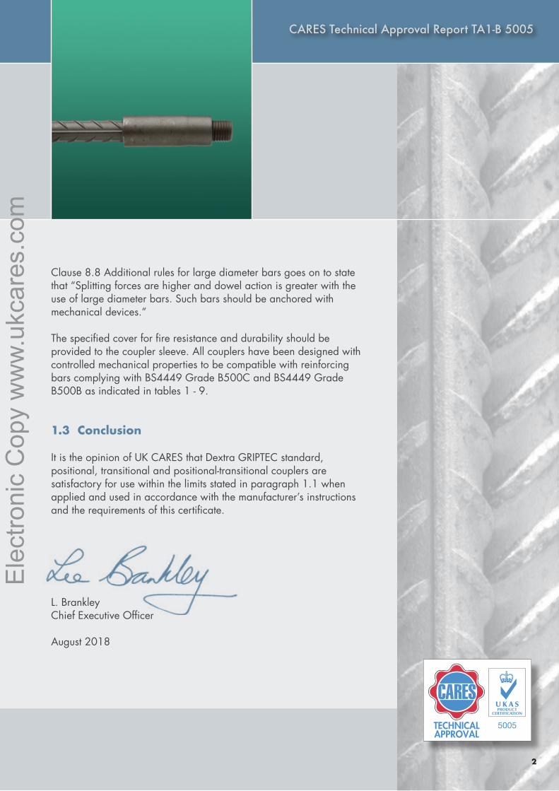
1.3 Conclusion
It is the opinion of UK CARES that Dextra GRIPTEC standard, positional, transitional and positional-transitional couplers are satisfactory for use within the limits stated in paragraph 1.1 when applied and used in accordance with the manufacturer’s instructions and the requirements of this certificate.
L. BrankleyChief Executive Officer
August 2018
Ele
ctro
nic
Cop
y w
ww
.ukc
ares
.com
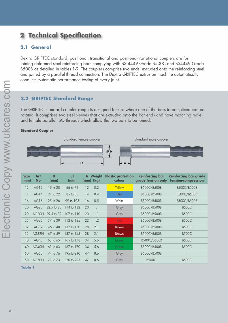
2 TechnicalSpecification
3
2.1 General
Dextra GRIPTEC standard, positional, transitional and positional-transitional couplers are for joining deformed steel reinforcing bars complying with BS 4449 Grade B500C and BS4449 Grade B500B as detailed in tables 1-9. The couplers comprise two ends, extruded onto the reinforcing steel and joined by a parallel thread connection. The Dextra GRIPTEC extrusion machine automatically conducts systematic performance testing of every joint.
2.2 GRIPTEC Standard Range The GRIPTEC standard coupler range is designed for use where one of the bars to be spliced can be rotated. It comprises two steel sleeves that are extruded onto the bar ends and have matching male and female parallel ISO threads which allow the two bars to be joined.
Standard Coupler
L1 A
ø D
Standard female coupler Standard male coupler
Size Art D L1 A Weight Plastic protection Reinforcing bar Reinforcing bar grade (mm) No (mm) (mm) (mm) (kg) colour grade tension only tension-compression
12 AG12 19 to 20 66 to 72 12 0.2 Yellow B500C/B500B B500C/B500B
14 AG14 21 to 22 85 to 88 14 0.4 Blue B500C/B500B B500C/B500B
16 AG16 25 to 26 99 to 103 16 0.5 White B500C/B500B B500C/B500B
20 AG20 32.5 to 35 114 to 132 20 1.1 Grey B500C/B500B B500C
20 AG20N 29.5 to 32 107 to 110 20 1.1 Grey B500C/B500B B500C
25 AG25 37 to 39 112 to 125 22 1.2 Red B500C/B500B B500C
32 AG32 46 to 48 137 to 150 28 2.1 Brown B500C/B500B B500C
32 AG32N 47 to 49 137 to 143 28 2.1 Brown B500C/B500B B500C
40 AG40 63 to 65 165 to 178 34 5.6 Green B500C/B500B B500C
40 AG40N 61 to 63 167 to 170 34 5.6 Green B500C/B500B B500C
50 AG50 74 to 76 195 to 210 47 8.6 Grey B500C/B500B -
50 AG50N 71 to 73 220 to 225 47 8.6 Grey B500C B500C
Table 1
Ele
ctro
nic
Cop
y w
ww
.ukc
ares
.com
Ele
ctro
nic
Cop
y w
ww
.ukc
ares
.com
CARES Technical Approval Report TA1-B-5012
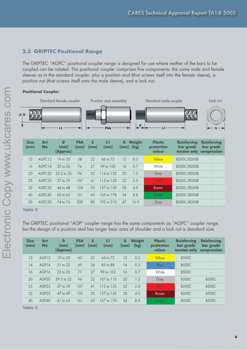
2.3 GRIPTEC Positional Range The GRIPTEC “AGPC” positional coupler range is designed for use where neither of the bars to be coupled can be rotated. The positional coupler comprises five components: the same male and female sleeves as in the standard coupler, plus a position stud (that screws itself into the female sleeve), a position nut (that screws itself onto the male sleeve), and a lock nut.
The GRIPTEC positional “AGP” coupler range has the same components as “AGPC” coupler range, but the design of a position stud has larger bear area of shoulder and a lock nut is standard size.
Positional Coupler
CARES Technical Approval Report TA1-B 5005
Standard female coupler Standard male coupler Lock nutPosition stud assembly
ø D
L1 PSA L1A
S
Size Art D PSA S L1 A Weight Plastic Reinforcing Reinforcing (mm) No (mm) (mm) (mm) (mm) (mm) (kg) protection bar grade bar grade (Approx) colour tension only compression
12 AGPC12 19 to 20 58 22 66 to 72 12 0.3 Yellow B500C/B500B -
16 AGPC16 25 to 26 76 27 99 to 103 16 0.7 White B500C/B500B -
20 AGPC20 32.5 to 35 94 32 114 to 132 20 1.5 Grey B500C/B500B -
25 AGPC25 37 to 39 107 41 112 to 125 22 2.0 Red B500C/B500B -
32 AGPC32 46 to 48 124 50 137 to 150 28 4.0 Brown B500C/B500B -
40 AGPC40 63 to 65 151 65 165 to 178 34 8.8 Green B500C/B500B -
50 AGPC50 74 to 76 200 80 195 to 210 47 16.9 Grey B500C/B500B -
Size Art D PSA S L1 A Weight Plastic Reinforcing Reinforcing (mm) No (mm) (mm) (mm) (mm) (mm) (kg) protection bar grade bar grade (Approx) colour tension only compression
12 AGP12 19 to 20 60 22 66 to 72 12 0.3 Yellow B500C -
14 AGP14 21 to 22 69 24 85 to 88 14 0.5 Blue B500C -
16 AGP16 25 to 26 77 27 99 to 103 16 0.7 White B500C -
20 AGP20 29.5 to 32 94 32 107 to 110 20 1.5 Grey B500C B500C
25 AGP25 37 to 39 107 41 112 to 125 22 2.0 Red B500C B500C
32 AGP32 47 to 49 133 50 137 to 143 28 4.0 Brown B500C B500C
40 AGP40 61 to 63 161 65 167 to 170 34 8.8 Green B500C B500C
Table 2
Table 3
4
Ele
ctro
nic
Cop
y w
ww
.ukc
ares
.com
5
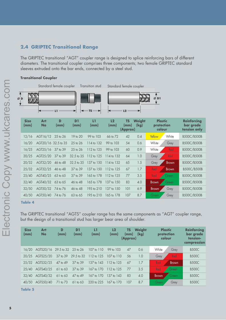
2.4 GRIPTEC Transitional Range The GRIPTEC transitional “AGT” coupler range is designed to splice reinforcing bars of different diameters. The transitional coupler comprises three components; two female GRIPTEC standard sleeves extruded onto the bar ends, connected by a steel stud.
Transitional Coupler
Standard female coupler Standard female couplerTransition stud
ø D ø D1
L1 TS L2
The GRIPTEC transitional “AGTS” coupler range has the same components as “AGT” coupler range, but the design of a transitional stud has larger bear area of shoulder.
Table 4
Size Art D D1 L1 L2 TS Weight Plastic Reinforcing (mm) No (mm) (mm) (mm) (mm) (mm) (kg) protection bar grade (Approx) colour tension only
12/16 AGT16/12 25 to 26 19 to 20 99 to 103 66 to 72 42 0.4 Yellow White B500C/B500B
16/20 AGT20/16 32.5 to 35 25 to 26 114 to 132 99 to 103 54 0.6 White Grey B500C/B500B
16/25 AGT25/16 37 to 39 25 to 26 112 to 125 99 to 103 60 0.9 White Red B500C/B500B
20/25 AGT25/20 37 to 39 32.5 to 35 112 to 125 114 to 132 64 1.0 Grey Red B500C/B500B
20/32 AGT32/20 46 to 48 32.5 to 35 137 to 150 114 to 132 65 1.5 Grey Brown B500C/B500B
25/32 AGT32/25 46 to 48 37 to 39 137 to 150 112 to 125 67 1.7 Red Brown B500C/B500B
25/40 AGT40/25 63 to 65 37 to 39 165 to 178 112 to 125 77 3.5 Red Green B500C/B500B
32/40 AGT40/32 63 to 65 46 to 48 165 to 178 137 to 150 83 4.0 Brown Green B500C/B500B
32/50 AGT50/32 74 to 76 46 to 48 195 to 210 137 to 150 101 6.9 Brown Grey B500C/B500B
40/50 AGT50/40 74 to 76 63 to 65 195 to 210 165 to 178 107 8.7 Green Grey B500C/B500B
Table 5
Size Art D D1 L1 L2 TS Weight Plastic Reinforcing (mm) No (mm) (mm) (mm) (mm) (mm) (kg) protection bar grade (Approx) colour tension- compression
16/20 AGTS20/16 29.5 to 32 25 to 26 107 to 110 99 to 103 47 0.6 White Grey B500C
20/25 AGTS25/20 37 to 39 29.5 to 32 112 to 125 107 to 110 56 1.0 Grey Red B500C
25/32 AGTS32/25 47 to 49 37 to 39 137 to 143 112 to 125 67 1.7 Red Brown B500C
25/40 AGTS40/25 61 to 63 37 to 39 167 to 170 112 to 125 77 3.5 Red Green B500C
32/40 AGTS40/32 61 to 63 47 to 49 167 to 170 137 to 143 83 4.0 Brown Green B500C
40/50 AGTS50/40 71 to 73 61 to 63 220 to 225 167 to 170 107 8.7 Green Grey B500C
Ele
ctro
nic
Cop
y w
ww
.ukc
ares
.com
Ele
ctro
nic
Cop
y w
ww
.ukc
ares
.com
CARES Technical Approval Report TA1-B-5012
6
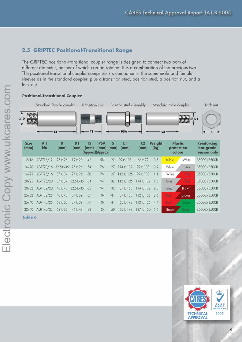
2.5 GRIPTEC Positional-Transitional Range The GRIPTEC positional-transitional coupler range is designed to connect two bars of different diameter, neither of which can be rotated. It is a combination of the previous two. The positional-transitional coupler comprises six components: the same male and female sleeves as in the standard coupler, plus a transition stud, position stud, a position nut, and a lock nut.
Positional-Transitional Coupler
TECHNICALAPPROVAL
5005
CARES Technical Approval Report TA1-B 5005
Table 6
Size Art D D1 TS PSA S L1 L2 Weight Plastic Reinforcing (mm) No (mm) (mm) (mm) (mm) (mm) (mm) (mm) (kg) protection bar grade (Approx) (Approx) colour tension only
12/16 AGPT16/12 25 to 26 19 to 20 42 58 22 99 to 103 66 to 72 0.5 Yellow White B500C/B500B
16/20 AGPT20/16 32.5 to 35 25 to 26 54 76 27 114 to 132 99 to 103 0.9 White Grey B500C/B500B
16/25 AGPT25/16 37 to 39 25 to 26 60 76 27 112 to 125 99 to 103 1.1 White Red B500C/B500B
20/25 AGPT25/20 37 to 39 32.5 to 35 64 94 32 112 to 125 114 to 132 1.6 Grey Red B500C/B500B
20/32 AGPT32/20 46 to 48 32.5 to 35 65 94 32 137 to 150 114 to 132 2.0 Grey Brown B500C/B500B
25/32 AGPT32/25 46 to 48 37 to 39 67 107 41 137 to 150 112 to 125 2.6 Red Brown B500C/B500B
25/40 AGPT40/25 63 to 65 37 to 39 77 107 41 165 to 178 112 to 125 4.4 Red Green B500C/B500B
32/40 AGPT40/32 63 to 65 46 to 48 83 124 50 165 to 178 137 to 150 5.4 Brown Green B500C/B500B
Standard female coupler Standard male coupler Lock nut Transition stud Position stud assembly
ø D ø D1
L1 TS PSA L2 S Size Art D D1 L1 L2 TS Weight Plastic Reinforcing (mm) No (mm) (mm) (mm) (mm) (mm) (kg) protection bar grade (Approx) colour tension only
12/16 AGT16/12 25 to 26 19 to 20 99 to 103 66 to 72 42 0.4 Yellow White B500C/B500B
16/20 AGT20/16 32.5 to 35 25 to 26 114 to 132 99 to 103 54 0.6 White Grey B500C/B500B
16/25 AGT25/16 37 to 39 25 to 26 112 to 125 99 to 103 60 0.9 White Red B500C/B500B
20/25 AGT25/20 37 to 39 32.5 to 35 112 to 125 114 to 132 64 1.0 Grey Red B500C/B500B
20/32 AGT32/20 46 to 48 32.5 to 35 137 to 150 114 to 132 65 1.5 Grey Brown B500C/B500B
25/32 AGT32/25 46 to 48 37 to 39 137 to 150 112 to 125 67 1.7 Red Brown B500C/B500B
25/40 AGT40/25 63 to 65 37 to 39 165 to 178 112 to 125 77 3.5 Red Green B500C/B500B
32/40 AGT40/32 63 to 65 46 to 48 165 to 178 137 to 150 83 4.0 Brown Green B500C/B500B
32/50 AGT50/32 74 to 76 46 to 48 195 to 210 137 to 150 101 6.9 Brown Grey B500C/B500B
40/50 AGT50/40 74 to 76 63 to 65 195 to 210 165 to 178 107 8.7 Green Grey B500C/B500B
Size Art D D1 L1 L2 TS Weight Plastic Reinforcing (mm) No (mm) (mm) (mm) (mm) (mm) (kg) protection bar grade (Approx) colour tension- compression
16/20 AGTS20/16 29.5 to 32 25 to 26 107 to 110 99 to 103 47 0.6 White Grey B500C
20/25 AGTS25/20 37 to 39 29.5 to 32 112 to 125 107 to 110 56 1.0 Grey Red B500C
25/32 AGTS32/25 47 to 49 37 to 39 137 to 143 112 to 125 67 1.7 Red Brown B500C
25/40 AGTS40/25 61 to 63 37 to 39 167 to 170 112 to 125 77 3.5 Red Green B500C
32/40 AGTS40/32 61 to 63 47 to 49 167 to 170 137 to 143 83 4.0 Brown Green B500C
40/50 AGTS50/40 71 to 73 61 to 63 220 to 225 167 to 170 107 8.7 Green Grey B500C
Ele
ctro
nic
Cop
y w
ww
.ukc
ares
.com
7
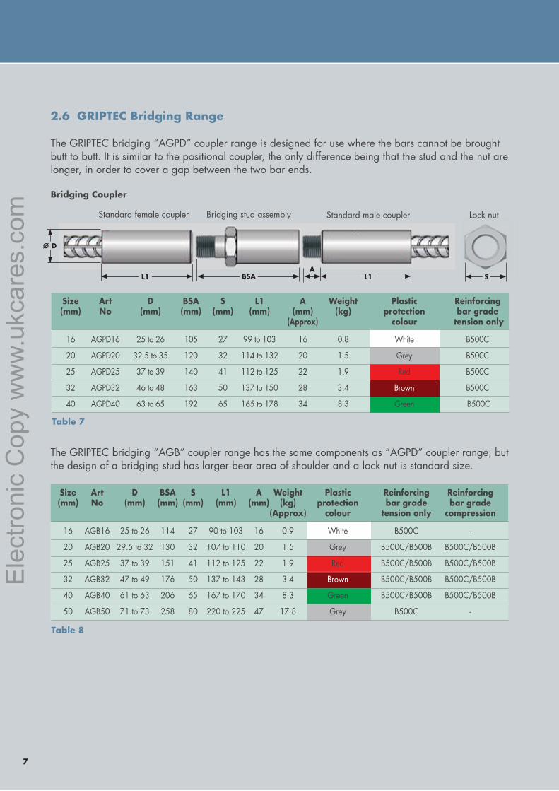
2.6 GRIPTEC Bridging Range The GRIPTEC bridging “AGPD” coupler range is designed for use where the bars cannot be brought butt to butt. It is similar to the positional coupler, the only difference being that the stud and the nut are longer, in order to cover a gap between the two bar ends.
The GRIPTEC bridging “AGB” coupler range has the same components as “AGPD” coupler range, but the design of a bridging stud has larger bear area of shoulder and a lock nut is standard size.
Bridging Coupler
Standard female coupler Standard male couplerBridging stud assembly
ø D
L1 BSA L1
Lock nut
SA
Table 7
Table 8
Size Art D BSA S L1 A Weight Plastic Reinforcing (mm) No (mm) (mm) (mm) (mm) (mm) (kg) protection bar grade (Approx) colour tension only
16 AGPD16 25 to 26 105 27 99 to 103 16 0.8 White B500C
20 AGPD20 32.5 to 35 120 32 114 to 132 20 1.5 Grey B500C
25 AGPD25 37 to 39 140 41 112 to 125 22 1.9 Red B500C
32 AGPD32 46 to 48 163 50 137 to 150 28 3.4 Brown B500C
40 AGPD40 63 to 65 192 65 165 to 178 34 8.3 Green B500C
Size Art D BSA S L1 A Weight Plastic Reinforcing Reinforcing (mm) No (mm) (mm) (mm) (mm) (mm) (kg) protection bar grade bar grade (Approx) colour tension only compression
16 AGB16 25 to 26 114 27 90 to 103 16 0.9 White B500C -
20 AGB20 29.5 to 32 130 32 107 to 110 20 1.5 Grey B500C/B500B B500C/B500B
25 AGB25 37 to 39 151 41 112 to 125 22 1.9 Red B500C/B500B B500C/B500B
32 AGB32 47 to 49 176 50 137 to 143 28 3.4 Brown B500C/B500B B500C/B500B
40 AGB40 61 to 63 206 65 167 to 170 34 8.3 Green B500C/B500B B500C/B500B
50 AGB50 71 to 73 258 80 220 to 225 47 17.8 Grey B500C -
Ele
ctro
nic
Cop
y w
ww
.ukc
ares
.com
Ele
ctro
nic
Cop
y w
ww
.ukc
ares
.com

CARES Technical Approval Report TA1-B-5012
8
TECHNICALAPPROVAL
5005
CARES Technical Approval Report TA1-B 5005
2.7 GRIPTEC Caging Range The GRIPTEC caging “GCA” coupler range is designed for use when the two bars are not well aligned (as it happens often in the manufacturing of reinforcement cages). This splice uses two standard GRIPTEC female couplers that are connected by a GRIPTEC “Caging assembly set”, which is constituted of a taper stud, a long caging stud, a caging nut and a lock-nut which are pre-assembled together. The tapered caging stud is screwed into a female sleeve (typically on the bottom bar), while, the set of a long caging stud, a caging nut and a lock-nut is screwed onto another female sleeve. Then, in order to accomplish the connection, the caging nut is screwed out of the caging stud and onto the tapered caging stud. The two bars do not need to be brought butt-to-butt: the GRIPTEC caging splice system can bridge a gap between the bars.
Caging Coupler
Table 9
Size Art D1 D2 L1 A L2 Weight Plastic Reinforcing Reinforcing (mm) No (mm) (mm) (mm) (mm) (mm) (kg) protection bar grade bar grade colour tension only compression
32 GCA32 47 to 49 50 137 to 143 28.5 226 3.7 Brown B500C/B500B -
40 GCA40 63 to 65 65 167 to 170 35 269 7.4 Green B500C/B500B B500C/B500B
50 GCA50 71 to 73 80 220 to 225 48 317 13.0 Grey B500C B500C
Standard female coupler Caging assembly set Standard female coupler
øD1
L1A A
L2
Size Art D BSA S L1 A Weight Plastic Reinforcing (mm) No (mm) (mm) (mm) (mm) (mm) (kg) protection bar grade (Approx) colour tension only
16 AGPD16 25 to 26 105 27 99 to 103 16 0.8 White B500C
20 AGPD20 32.5 to 35 120 32 114 to 132 20 1.5 Grey B500C
25 AGPD25 37 to 39 140 41 112 to 125 22 1.9 Red B500C
32 AGPD32 46 to 48 163 50 137 to 150 28 3.4 Brown B500C
40 AGPD40 63 to 65 192 65 165 to 178 34 8.3 Green B500C
L1
øD1øD2
Ele
ctro
nic
Cop
y w
ww
.ukc
ares
.com
9
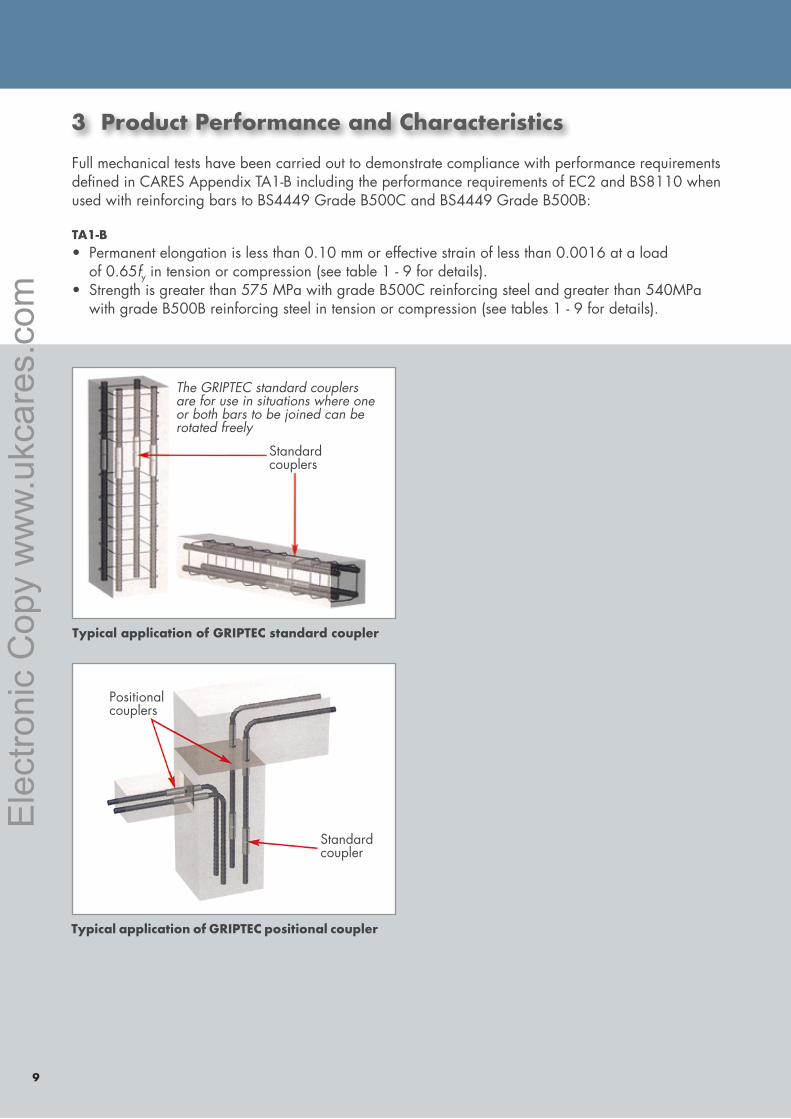
3 Product Performance and CharacteristicsFull mechanical tests have been carried out to demonstrate compliance with performance requirements defined in CARES Appendix TA1-B including the performance requirements of EC2 and BS8110 when used with reinforcing bars to BS4449 Grade B500C and BS4449 Grade B500B:
TA1-B• Permanent elongation is less than 0.10 mm or effective strain of less than 0.0016 at a load of 0.65fy in tension or compression (see table 1 - 9 for details). • Strength is greater than 575 MPa with grade B500C reinforcing steel and greater than 540MPa with grade B500B reinforcing steel in tension or compression (see tables 1 - 9 for details).
The GRIPTEC standard couplers are for use in situations where one or both bars to be joined can be rotated freely
Standard couplers
Standard coupler
Positional couplers
Typical application of GRIPTEC standard coupler
Typical application of GRIPTEC positional coupler
Ele
ctro
nic
Cop
y w
ww
.ukc
ares
.com
Ele
ctro
nic
Cop
y w
ww
.ukc
ares
.com
10
TECHNICALAPPROVAL
5005
CARES Technical Approval Report TA1-B 5005
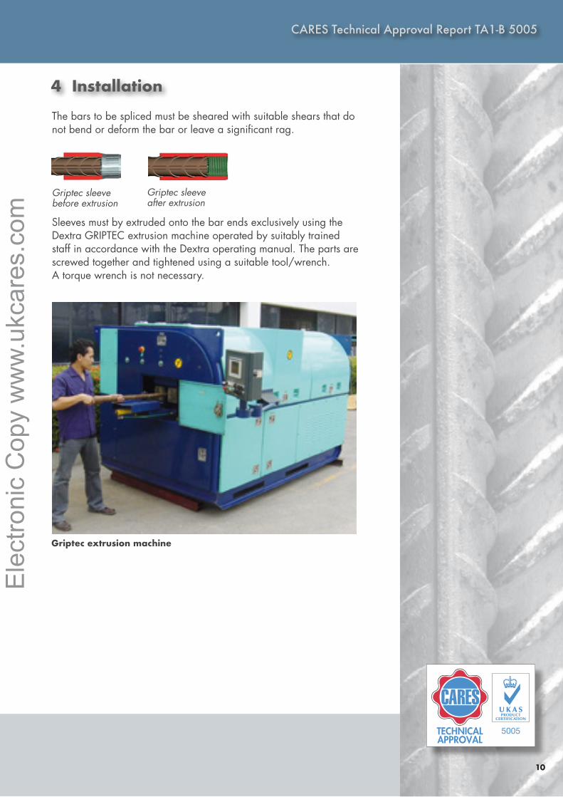
4 Installation
The bars to be spliced must be sheared with suitable shears that do not bend or deform the bar or leave a significant rag.
Sleeves must by extruded onto the bar ends exclusively using the Dextra GRIPTEC extrusion machine operated by suitably trained staff in accordance with the Dextra operating manual. The parts are screwed together and tightened using a suitable tool/wrench. A torque wrench is not necessary.
Griptec sleeve before extrusion
Griptec sleeve after extrusion
Griptec extrusion machine
Ele
ctro
nic
Cop
y w
ww
.ukc
ares
.com
11
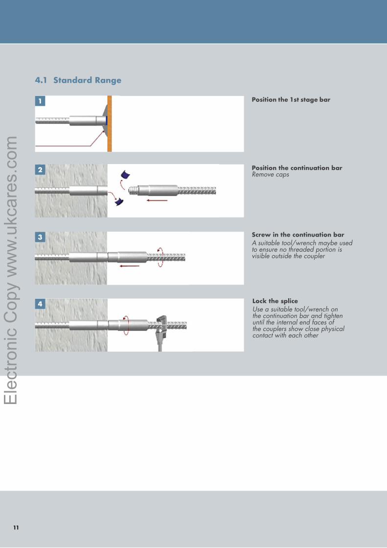
4.1 Standard Range
Position the 1st stage bar
Position the continuation bar Remove caps
Screw in the continuation barA suitable tool/wrench maybe used to ensure no threaded portion is visible outside the coupler
Lock the spliceUse a suitable tool/wrench on the continuation bar and tighten until the internal end faces of the couplers show close physical contact with each other
1
2
3
4
Ele
ctro
nic
Cop
y w
ww
.ukc
ares
.com
Ele
ctro
nic
Cop
y w
ww
.ukc
ares
.com
12
CARES Technical Approval Report TA1-B 5005
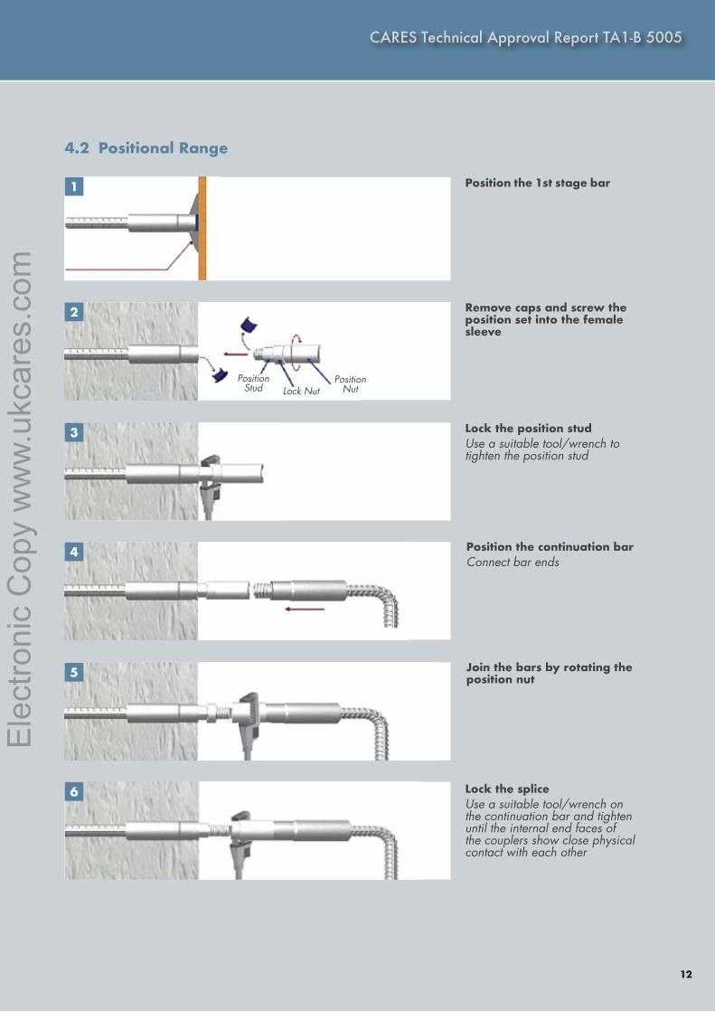
4.2 Positional Range
Position the 1st stage bar
Remove caps and screw the position set into the female sleeve
Lock the position studUse a suitable tool/wrench to tighten the position stud
Position the continuation barConnect bar ends
Join the bars by rotating the position nut
Lock the spliceUse a suitable tool/wrench on the continuation bar and tighten until the internal end faces of the couplers show close physical contact with each other
1
2
3
4
5
6
PositionStud Lock Nut
Position Nut
Ele
ctro
nic
Cop
y w
ww
.ukc
ares
.com
13
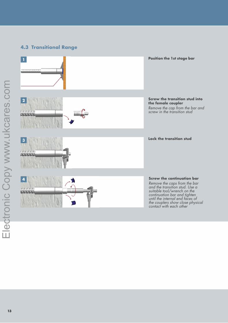
4.3 Transitional Range
Position the 1st stage bar
Screw the transition stud into the female couplerRemove the cap from the bar and screw in the transition stud
Lock the transition stud
Screw the continuation barRemove the caps from the bar and the transition stud. Use a suitable tool/wrench on the continuation bar and tighten until the internal end faces of the couplers show close physical contact with each other
1
2
3
4
Ele
ctro
nic
Cop
y w
ww
.ukc
ares
.com
Ele
ctro
nic
Cop
y w
ww
.ukc
ares
.com
14
TECHNICALAPPROVAL
5005
CARES Technical Approval Report TA1-B 5005
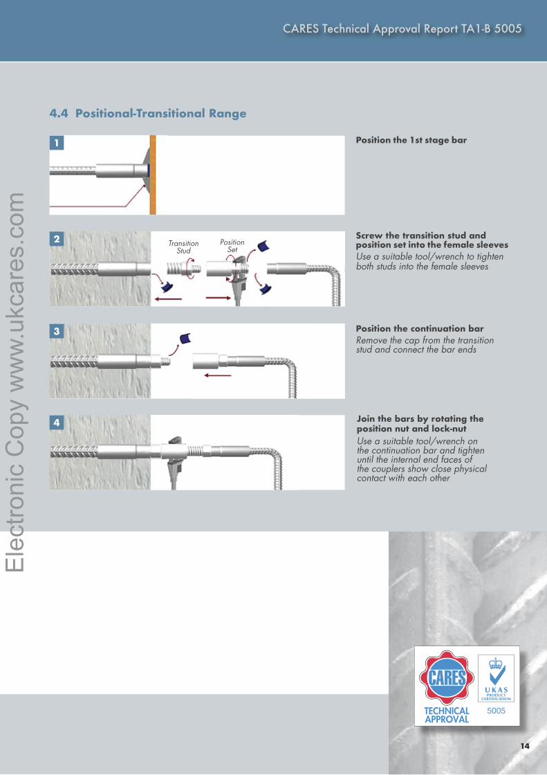
4.4 Positional-Transitional Range
Position the 1st stage bar
Screw the transition stud and position set into the female sleevesUse a suitable tool/wrench to tighten both studs into the female sleeves
Position the continuation barRemove the cap from the transition stud and connect the bar ends
Join the bars by rotating the position nut and lock-nutUse a suitable tool/wrench on the continuation bar and tighten until the internal end faces of the couplers show close physical contact with each other
1
2
3
4
TransitionStud
PositionSet
Ele
ctro
nic
Cop
y w
ww
.ukc
ares
.com
15
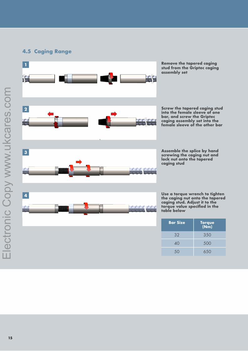
4.5 Caging Range
Remove the tapered caging stud from the Griptec caging assembly set
Screw the tapered caging stud into the female sleeve of one bar, and screw the Griptec caging assembly set into the female sleeve of the other bar
Assemble the splice by hand screwing the caging nut and lock nut onto the tapered caging stud
Use a torque wrench to tighten the caging nut onto the tapered caging stud. Adjust it to the torquevaluespecifiedinthetable below
1
2
3
4
Bar Size Torque (Nm)
32 350
40 500
50 650 Ele
ctro
nic
Cop
y w
ww
.ukc
ares
.com
Ele
ctro
nic
Cop
y w
ww
.ukc
ares
.com
16
TECHNICALAPPROVAL
5005
CARES Technical Approval Report TA1-B 5005
5 Safety Considerations
Couplers are supplied in wooden containers which have a maximum weight of 2500 kg and must be handled with appropriate lifting equipment. It is advisable to wear protective gloves during handling the containers, couplers and reinforcement; during the extrusion process and during coupler installation.
6 Product Testing and Evaluation
7 Quality Assurance
Dextra GRIPTEC extruded couplers have been tested to satisfy the requirements of EC2 and BS8110 when used with reinforcing bars to BS4449 Grade B500C and BS4449 Grade B500B. The testing comprised the following elements:
TA1-B, BS8110 and EC2• Tensile Strength• Permanent Deformation
The products are subject to a programme of periodic testing to ensure that they remain within the performance limits of this technical approval.
Dextra GRIPTEC extruded couplers are produced under an BS EN ISO9001 quality assurance system certified by CARES. The quality assurance scheme monitors the production of the couplers and ensures that materials and geometry remain within the limits of this technical approval.
Ele
ctro
nic
Cop
y w
ww
.ukc
ares
.com
17
8 Building Regulations
8.1 The Building Regulations (England and Wales)
Structure, Approved Document A
Dextra GRIPTEC parallel extruded couplers, when used in EC2 based designs using the data contained within this technical approval, satisfy the relevant requirements of The Building Regulations, Approved Document A.
Materials and Workmanship, Approved Document
This technical approval gives assurance that the Dextra GRIPTEC parallel extruded couplers comply with the material requirements of EC2.
8.2 The Building Regulations (Northern Ireland)
Materials and Workmanship
This technical approval gives assurance that Dextra GRIPTEC parallel extruded couplers comply with the material requirements of EC2 by virtue of regulation 23, Deemed to satisfy provisions regarding the fitness of materials and workmanship.
8.3 The Building Standards (Scotland)
Fitness of Materials
This technical approval gives assurance that Dextra GRIPTEC parallel extruded couplers comply with the material requirements of EC2 by virtue of Clause 0.8.
Structure
Dextra GRIPTEC parallel extruded couplers, when used in EC2 based designs using the data contained within this technical approval, satisfy the requirements of The Building Standards (Scotland) Clause 1.
Ele
ctro
nic
Cop
y w
ww
.ukc
ares
.com
Ele
ctro
nic
Cop
y w
ww
.ukc
ares
.com
18
TECHNICALAPPROVAL
5005
CARES Technical Approval Report TA1-B 5005
9 References
• BS 4449:2005 Steel for the reinforcement of concrete - Weldable reinforcing steel - Bar, coil and decoiled product - Specification.
• BS 8110:Part 1:1997 (amended 2007) Structural use of concrete, Code of practice for design and construction.
• BS EN 1992-1-1:2004 Eurocode 2 Design of concrete structures - General rules for buildings
• BS EN ISO 9001:2008 Quality Systems. Model for quality assurance in production, installation and servicing.
• TA1-B Quality and Operations Schedule for the Technical Approval of Couplers for Reinforcing Steel For BS8110 and EN1992-1-1 Applications for Static Loading in Tension or Tension and Compression.
Ele
ctro
nic
Cop
y w
ww
.ukc
ares
.com
10 Conditions
1. The quality of the materials and method of manufacture have been examined by CARES and found to be satisfactory. This technical approval will remain valid provided that:
a. The product design and specification are unchanged. b. The materials, method of manufacture and location are unchanged. c. The manufacturer complies with CARES regulations for technical approvals. d. The manufacturer holds a valid CARES Certificate of Product Assessment. e. The product is installed and used as described in this report.
2. CARES make no representation as to the presence or absence of patent rights subsisting in the product and/or the legal right of DEXTRA to market the product.
3. Any references to standards, codes or legislation are those which are in force at the date of this certificate.
4. Any recommendations relating to the safe use of this product are the minimum standards required when the product is used. These requirements do not purport to satisfy the requirements of the Health and Safety at Work act 1974 or any other relevant safety legislation.
5. CARES does not accept any responsibility for any loss or injury arising as a direct or indirect result of the use of this product.
6. This Technical Approval Report should be read in conjunction with CARES Certificate of Product Assessment No 5005. Confirmation that this technical approval is current can be obtained from UK CARES.
19
Ele
ctro
nic
Cop
y w
ww
.ukc
ares
.com
Ele
ctro
nic
Cop
y w
ww
.ukc
ares
.com
CARES Technical Approval Report TA1-B 5005
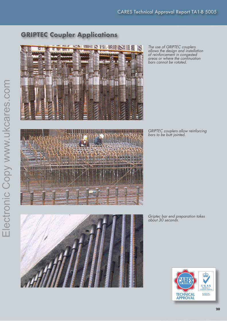
GRIPTEC Coupler Applications
The use of GRIPTEC couplers allows the design and installation of reinforcement in congested areas or where the continuation bars cannot be rotated.
GRIPTEC couplers allow reinforcing bars to be butt jointed.
Griptec bar end preparation takes about 30 seconds.
20
TECHNICALAPPROVAL
5005
Ele
ctro
nic
Cop
y w
ww
.ukc
ares
.com
21
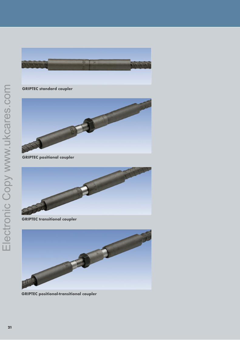
GRIPTEC standard coupler
GRIPTEC positional coupler
GRIPTEC transitional coupler
GRIPTEC positional-transitional coupler
Ele
ctro
nic
Cop
y w
ww
.ukc
ares
.com
���TECHNICALAPPROVALUK CARES
Pembroke House21 Pembroke RoadSevenoaksKent TN13 1XR
Phone: +44(0)1732 450000Fax: +44(0)1732 455917E-mail: [email protected]: www.ukcares.com
Independent Product Assessments for the Construction Industry
Copyright UK CARES © 3.9.
18
Ele
ctro
nic
Cop
y w
ww
.ukc
ares
.com