carr powerfuge technology - celldcelld.com/documents-pdf/carr powerfuge machine overview.pdf ·...
TRANSCRIPT
CARR Powerfuge
Technology

CARRCARR®® PowerfugePowerfuge®®
• Powerful liquid/solids separations (20.000 x g)
P6Pilot P12 P18
• Scalable Solutions
– up to 1.700 L/h
• Automated solids recovery
• TrueClean™ design
– enabling CIP/SIP Validation

ApplicationsApplications
• Biotechnology
– E. Coli Cells
– Cell Lysates
– Inclusion Bodies
– Protein Precipitates
– Yeast Processing
• Pharmaceuticals
– Final Dosage Formation
• Specialty Chemicals
– Inkjet Ink, Photo resist, Silica
– Difficult, high-valued separations

DriveAssembly
ScraperScraper
Bearing Bearing HousingHousing
SwinglockSwinglock
Bowl CaseBowl Case
BowlBowl
CentrateCentrateCaseCase
LowerLowerCaseCase
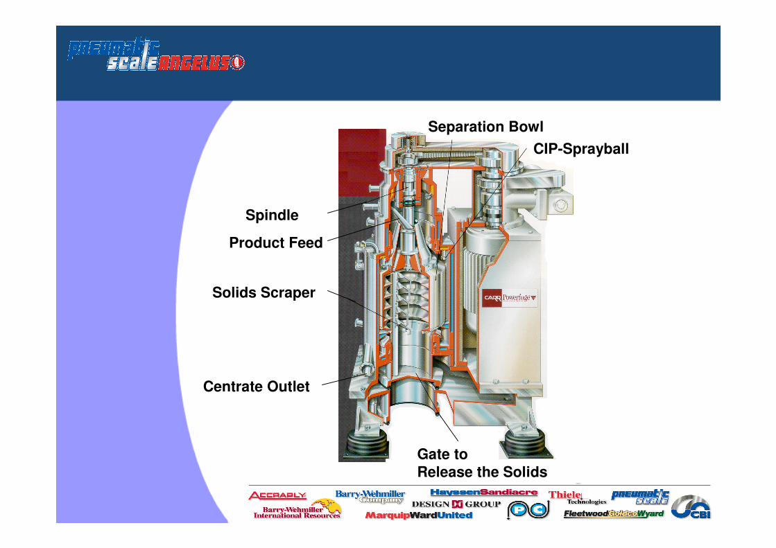
Separation Bowl
CIP-Sprayball
Gate to
Release the Solids
Solids Scraper
Spindle
Product Feed
Centrate Outlet
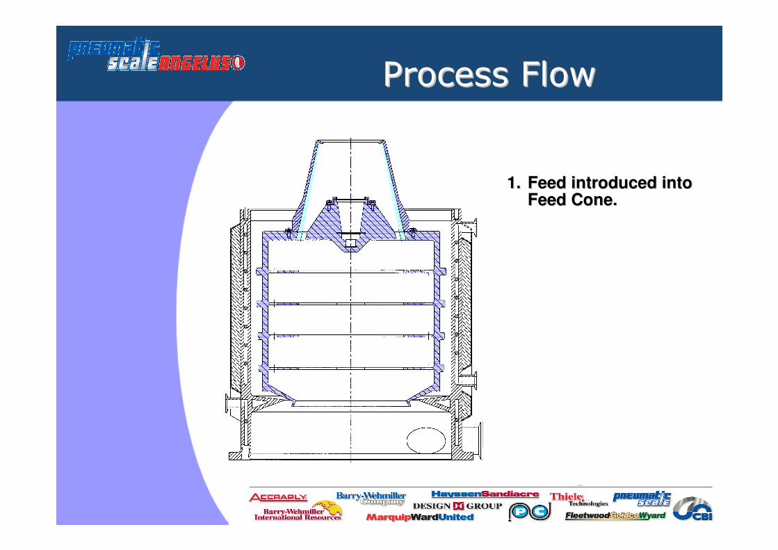
Process FlowProcess Flow
1. 1. Feed introduced into Feed introduced into Feed Cone.Feed Cone.
Process FlowProcess Flow
1. 1. 1. Feed introduced into Feed introduced into Feed introduced into Feed Cone.Feed Cone.Feed Cone.
2. 2. Feed then enters Bowl Feed then enters Bowl up to holes in Bafflesup to holes in Baffles..

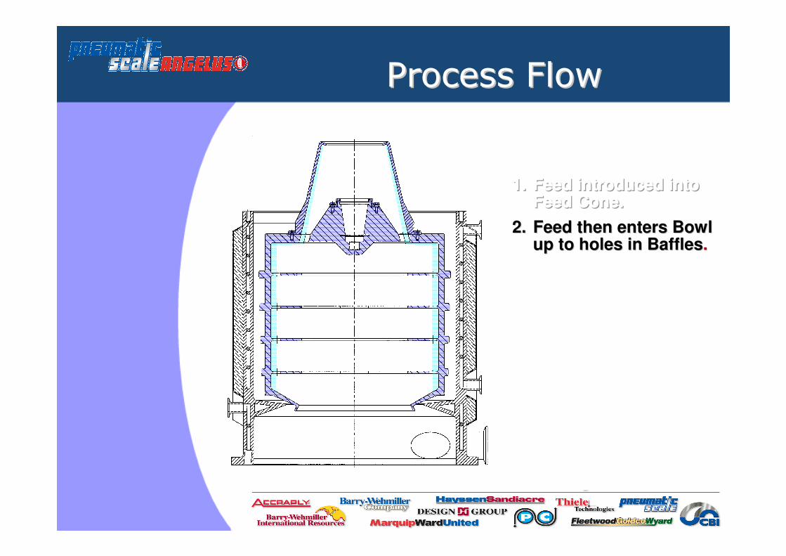
Process FlowProcess Flow
1. 1. 1. Feed introduced into Feed introduced into Feed introduced into Feed Cone.Feed Cone.Feed Cone.
2. 2. 2. Feed then enters Bowl Feed then enters Bowl Feed then enters Bowl up to holes in Baffles.up to holes in Baffles.up to holes in Baffles.
3. 3. Feed fills Bowl up to Feed fills Bowl up to Bowl Lip.Bowl Lip.

Process FlowProcess Flow
1. 1. 1. Feed introduced into Feed introduced into Feed introduced into Feed Cone.Feed Cone.Feed Cone.
2. 2. 2. Feed then enters Bowl Feed then enters Bowl Feed then enters Bowl up to holes in Baffles.up to holes in Baffles.up to holes in Baffles.
3. 3. 3. Feed fills Bowl up to Feed fills Bowl up to Feed fills Bowl up to the Bowl Lip.the Bowl Lip.the Bowl Lip.
4. 4. Feed decants from Feed decants from Bowl Lip into plenumBowl Lip into plenum..Pool Surface

Process FlowProcess Flow
1. 1. 1. Feed introduced into Feed introduced into Feed introduced into Feed Cone.Feed Cone.Feed Cone.
2. 2. 2. Feed then enters Bowl Feed then enters Bowl Feed then enters Bowl up to holes in Baffles.up to holes in Baffles.up to holes in Baffles.
3. 3. 3. Feed fills Bowl up to the Feed fills Bowl up to the Feed fills Bowl up to the Bowl Lip.Bowl Lip.Bowl Lip.
4. 4. 4. Feed decants from Bowl Feed decants from Bowl Feed decants from Bowl Lip into plenum.Lip into plenum.Lip into plenum.
5. 5. Centrate accumulates in Centrate accumulates in plenum and flows out plenum and flows out from Centrate Port.from Centrate Port.
Pool Surface

Process FlowProcess Flow
1. 1. 1. Feed introduced into Feed introduced into Feed introduced into Feed Cone.Feed Cone.Feed Cone.
2. 2. 2. Feed then enters Bowl Feed then enters Bowl Feed then enters Bowl up to holes in Baffles.up to holes in Baffles.up to holes in Baffles.
3. 3. 3. Feed fills Bowl up to the Feed fills Bowl up to the Feed fills Bowl up to the Bowl Lip.Bowl Lip.Bowl Lip.
4. 4. 4. Feed decants from Bowl Feed decants from Bowl Feed decants from Bowl Lip into plenum.Lip into plenum.Lip into plenum.
5. 5. 5. Centrate accumulates in Centrate accumulates in Centrate accumulates in plenum and flows out plenum and flows out plenum and flows out from Centrate Port.from Centrate Port.from Centrate Port.
6. 6. Solids separate and Solids separate and pack against Bowl wall.pack against Bowl wall.
Pool Surface

Automated Solids RemovalAutomated Solids Removal
• Continuously feed bowl until
solids capacity is reached
• Decelerate to complete stop,
drain bowl
• Engage scraper drive at low
RPM, scraper arm advances
into cake, discharging solids
into chute
• Initiate next feeding cycle or
proceed to CIP/SIP operations

Powerfuge PilotPowerfuge Pilot
Specifications:
• Maximum G-Force 20.000 x g
• Maximum Speed 15.325 rpm
• Maximum Flow Rate 1 L/min
• Operating temperature 2-40ºC
• Jacketed Bowl Case (cooling)
• Pellet capacity of 1 L
• Bowl Volume 1,1L

Powerfuge PilotPowerfuge Pilot

Powerfuge P6Powerfuge P6
Specifications:
• Force – 20.000xg
• Total bowl volume 1,1 Liters
• Sediment volume 1,0 Liters
• Flow rate capacity up to 60 L/h
• 316L Stainless Steel Case
• Titanium Bowl
• USP Class VI Elastomers
• 1,5 horsepower 230V/50 Hz/20A

Powerfuge P12Powerfuge P12
Specifications:
• Force – 20.000xg
• Total bowl volume 9,0 Liters
• Sediment volume 8,0 Liters
• Flow rate capacity up to 500 L/h
• 316L Stainless Steel Case
• Titanium Bowl
• USP Class VI Elastomers
• 10 horsepower 400V/50Hz/45A

Powerfuge P18Powerfuge P18
Specifications:
• Force – 20.000xg
• Total bowl volume 36 Liters
• Sediment volume 32 Liters
• Flow rate capacity up to 1.700 L/h
• 316L Stainless Steel Case
• Titanium Bowl
• USP Class VI Elastomers
• 30 horsepower 400V/50Hz/70A

Major AssembliesMajor Assemblies
DriveAssembly
ScraperScraper
Bearing Bearing HousingHousing
SwinglockSwinglock
Bowl CaseBowl Case
BowlBowl
CentrateCentrateCaseCase
LowerLowerCaseCase

cGMP CompliancecGMP Compliance
• True CleanTM Design
– Sanitary Design
– CIP
– SIP
• Automation
– Processing, Solids Removal, CIP/SIP
• Closed System Processing
• cGMP Documentation

True True CleanCleanTMTM Design Design -- CIPCIP
• Requires Sanitary Design
– All process wetted components
• 100% CIP Access
• Reproducible CIP Process
• Verification
– Swab tests consistent with other process steps

CIP Design PhilosophyCIP Design Philosophy
• Zone cleaning
• Short, high pressure bursts
• 100% coverage
• Typical 4-step cycle
• Fully automatic

CIP Wash ZonesCIP Wash Zones
Solids chute wash zone (reslurry
vessel or CIP cap)
Swinglock wash zone
Upper bearing
wash zone
Bowl casewash zone
Bowl/scraperwash zone
Feed pathwash zone
Lower case wash zone

CIP Validation CIP Validation -- RiboflavinRiboflavin
Test
• Dextrose/Riboflavin surface coverage
• Ambient water cycle
• Disassemble and view under black light
Acceptance
• No visible fluorescence

CIP Validation CIP Validation -- SwabSwab
Test
• Yeast, riboflavin process organics
• Run process
• Perform auto CIP cycle
• Repeat fluorescence inspection
• Swab 12 areas for TOC analysis
Acceptance
• All 12 swabs were below acceptable TOC limits

Customer ValidationCustomer Validation
“The TOC analysis of the samples shows that the centrifuge was very clean after both cleaning cycles. […] The centrifuge has been shown to be cleanable with the CIP cycles defined above and CIP 310 detergent. It is concluded that the final cycle parameters can easily be defined and validated.”
– Fortune 100 biopharmaceutical
company

SIP Design PhilosophySIP Design Philosophy
• Single point steam connection to header
• Steam to flow through all areas of machine
including auxiliary piping
• Steam/condensate outlets at all low points
and at all outer boundaries
– Ported valve assemblies
• Steam flow and sterilization temperature
throughout the entire system

SIP ValidationSIP Validation
• SIP Process is Validated
• (12) RTD’s placed throughout
system and ancillaries
• Steam injected into system
• Temperatures recorded on a Kaye
digistrip at 1 minute intervals
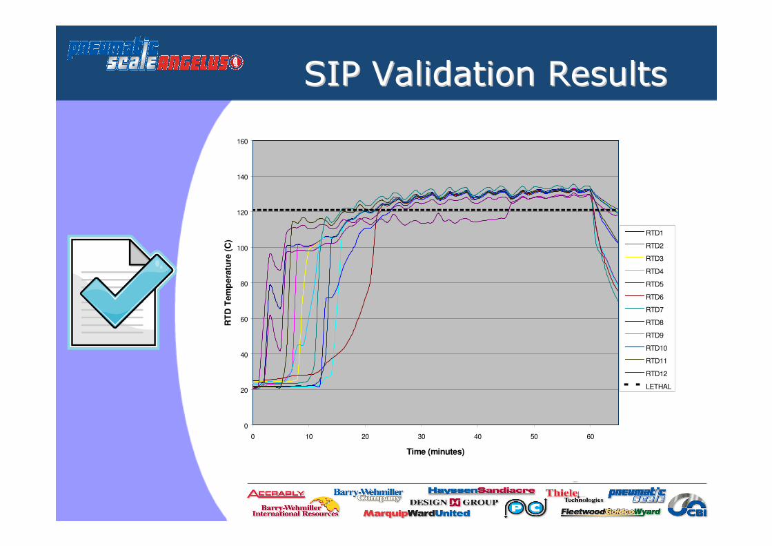
SIP Validation ResultsSIP Validation Results
0
20
40
60
80
100
120
140
160
0 10 20 30 40 50 60
Time (minutes)
RT
D T
em
pera
ture
(C
)RTD1
RTD2
RTD3
RTD4
RTD5
RTD6
RTD7
RTD8
RTD9
RTD10
RTD11
RTD12
LETHAL

cGMP DocumentationcGMP Documentation
Material Traceability• Material certificates and test reports
• Weld reports and inspection reports
In-Coming Materials
• Vendor qualification and auditing
• 100% inspection of fabricated and critical components
Documentation
• Documentation of System Configuration
• Complete documentation control & file management
• Engineering change order and customer approval process
• Final test report and procedures
• Operating manuals and engineering drawings

CARR Powerfuge CARR Powerfuge -- SummarySummary
• More Separating Force
– 20.000 x G for better performance, yield
– Superior liquid clarity
– Drier cakes
– Sub-micron clarification or classification
• Automated Processing
– No operator exposure
• Scalable Solutions
– Up to 1.700 LPH
• cGMP Compliance
– TrueClean™ design
– Enabling CIP/SIP validation
∑

Unmatched VersatilityUnmatched Versatility
Powerfuge
Disc Stack
Centrifuge
Tube Bowl
Centrifuge
Filtering
Centrifuge
Filter
Systems
High separating force
(20,000 G’s) b b
Ultra dry solids – easily
recovered b Possible
Submicron clarification b b b b
Auto solids discharge b b b Possible
Ease of maintenance b b
Sealed for safety/purity b b b b
No media disposal b b b