carrier grade open environment reference model
TRANSCRIPT

International Telecommunication Union
OpenCommunicationArchitectureForum
OpenCommunicationArchitectureForum
InternationalTelecommunicationUnion
InternationalTelecommunicationUnion
Open Communication Architecture Forum
OCAF Focus Group
Carrier Grade Open Environment Reference Model
Basis Version 1.0
May 2005
CGOE Reference Model Basis Version 1.0
2/77 May 2005
Table of Content Preface................................................................................................................................................... 4 1 Establishment of Reference Model ................................................................................................ 5 1.1 Selecting COTS Components .......................................................................................................10 1.2 Selecting Carrier Grade Capabilities .............................................................................................13 1.3 Selecting Open Standards and Interfaces.....................................................................................27 1.4 Selecting Properties, Relationships, and Boundaries ...................................................................33 2 Description of COTS Component Layers and Categories............................................................ 35 2.1 Server Hardware ...........................................................................................................................35 2.2 Base Operating Platform...............................................................................................................35 2.3 Extended Operating Platform........................................................................................................40 2.4 Industry Application.......................................................................................................................44 3 Description of Applicable COTS Components ............................................................................. 46 3.1 Basic Network Application Services ..............................................................................................46 3.2 Protocol Services ..........................................................................................................................46 3.3 Signaling Protocol Stacks .............................................................................................................46 3.4 OAM&P Middleware......................................................................................................................47 3.5 Database Middleware....................................................................................................................47 3.6 Data Model Services .....................................................................................................................48 3.7 System Model Services.................................................................................................................49 3.8 Platform Event Services ................................................................................................................50 3.9 Workload Management Services ..................................................................................................50 3.10 High Availability Services ..............................................................................................................51 3.11 Base IP Communications ..............................................................................................................53 4 Reference to Applicable Open Standards .................................................................................... 55 4.1 International Telecommunication Union........................................................................................55 4.2 Internet Engineering Task Force...................................................................................................56 4.3 ETSI TISPAN WG2 .......................................................................................................................57 4.4 Telcordia .......................................................................................................................................57 4.5 3rd Generation Partnership Program .............................................................................................57 4.6 Service AvailabilityTM Forum..........................................................................................................57 4.7 Distributed Management Task Force ............................................................................................60 4.8 Telecommunications Management Forum....................................................................................60 4.9 Open Mobile Alliance ....................................................................................................................61 4.10 Parlay Group .................................................................................................................................62 4.11 Organization for the Advancement of Structured Information Standards......................................64 4.12 The World Wide Web Consortium (W3C) .....................................................................................65 4.13 WS-I (Web Services Interoperability Organization).......................................................................65 4.14 Java Community Process..............................................................................................................65 4.15 Institute of Electrical and Electronics Engineers ...........................................................................66 4.16 Open Source Development Lab....................................................................................................66 4.17 Free Standards Group...................................................................................................................66 4.18 PCI Industrial Computer Manufacturer Group...............................................................................66 4.19 Storage Networking Industry Association......................................................................................66 5 Reference to Gaps in Open Standards ........................................................................................ 67 5.1 Topics of Emerging Standards ......................................................................................................67 5.2 Topics of Possible Helpful Standards............................................................................................67 5.3 Topics of “Vague” Standards.........................................................................................................67

CGOE Reference Model Basis Version 1.0
3/77 May 2005
6 Conformance to Reference Model ............................................................................................... 68 6.1 Objective .......................................................................................................................................68 6.2 Context ..........................................................................................................................................68 Appendix A – List of Acronyms ............................................................................................................ 70 Appendix B – Glossary of Terms ......................................................................................................... 72 Revision History
1. August 6, 2004 version 0.1 Create initial basis 2. August 9, 2004 version 0.1a Add section 2 content 3. August 20,2004 version 0.1b Start of integration of OCAF comments 4. September 14, 2004 version 0.1c 2nd version with integrated comments 5. October 26, 2004 version 0.1d 3rd version with integrated comments 6. November 3, 2004 version 0.2 Definition of the base for the version 0.2 /
review of v 0.1b finished 7. December 6, 2004 version 0.2 Release of the base for version 0.2 8. March 24, 2005 version 0.3 Definition of the base for the version 0.3 9. April 26, 2005 version 0.3a Added component and compliance content 10. April 29, 2005 version 0.3a Distribution for review and approval 11. May 9, 2005 version 0.3b Start of integration of OCAF comments 12. May 19, 2005 version 0.3c 2nd version with integrated comments 13. May 24, 2005 version 1.0 Release of the base for version 1.0
Authors, Contributors, and Editors
Name Company
Ed Bailey IBM
Max Bornschlegl Siemens AG
Jim Lawrence SAF, Clovis Solutions
Robert Withrow Nortel
Atsuyoshi Shirato NTT
Dr. Markus Leberecht SAF, Motorola
Kevin J. Smith SAF, Motorola
Michael Gilfix IBM
Dr. Johannes Prade Siemens AG
Bruce Anthony IBM
Terry Thio Cisco
Paul Farrow Nokia
CGOE Reference Model Basis Version 1.0
4/77 May 2005
PREFACE
Historically, the lack of openness in telecommunications solutions has not allowed flexible “plug and play” adoption of best-of-breed 3rd party components available in the market. The principal mission of the Open Communications Architecture Forum (OCAF) is to address this lack of openness by defining a comprehensive set of commercial off the shelf (COTS) components that enables the creation of network elements, platforms and applications based on a common reference model.
The Carrier Grade Open Environment (CGOE) is intended to be such a common reference model, based upon open industry standards and COTS components. The model addresses functional and non-functional service requirements using an Internet Protocol (IP) infrastructure with greater separation of logical connection and control functions from physical transport and gateway functions. Opening up elements of the services infrastructure performing control plane and transport plane functions for example, will allow the industry to promote best-of-breed component reuse and interoperability among multiple component vendors.
A must for many telecommunications industry solutions to evolve to open solutions using COTS components is they remain “carrier grade” from many vantage points. In particular for CGOE, applicable COTS components are expected to have at least one of the following carrier grade characteristics:
• Very high performance: support for large number of simultaneous sessions and a high count of transactions per a unit of time1
• Very high availability: support for a 99.999% or greater uptime for services along with predictable response times including overload situations (soft real time)
• Scalable from small to very large configurations
• Hardware and software upgrade without interruptions
• Efficient and uniform management interfaces
• Easy & efficient adaptation of protocols and interoperability across systems
• High level of security
• Controlled life cycle of the utilized resources
• Rapid development, testing and monitoring
• Cost-efficient operation
This document describes the CGOE reference model for open, carrier grade telecommunications solutions using COTS to support NGN. Included in the document are criteria for establishing the model. The intended audience for this document is service providers, solution providers, and technology providers building telecommunications solutions containing components from multiple, different, COTS software and hardware vendors. CGOE may be utilized by other industries besides the telecommunications industry such as the automation industry, the life sciences industry, and so forth… by adding industry specific enablers to the basic CGOE features.
1 A requirement might be thousands of transactions per second. There are many factors that might impact this number such as speed of the processor, transaction size, etc…
CGOE Reference Model Basis Version 1.0
5/77 May 2005
1 ESTABLISHMENT OF REFERENCE MODEL
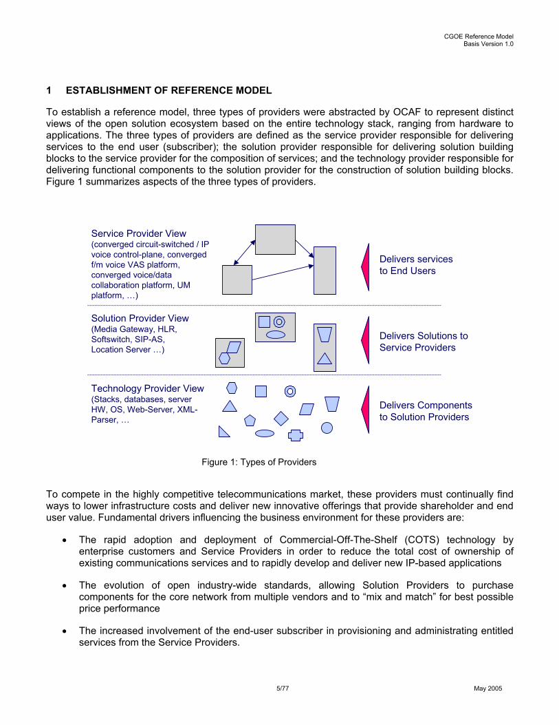
To establish a reference model, three types of providers were abstracted by OCAF to represent distinct views of the open solution ecosystem based on the entire technology stack, ranging from hardware to applications. The three types of providers are defined as the service provider responsible for delivering services to the end user (subscriber); the solution provider responsible for delivering solution building blocks to the service provider for the composition of services; and the technology provider responsible for delivering functional components to the solution provider for the construction of solution building blocks. Figure 1 summarizes aspects of the three types of providers.
Figure 1: Types of Providers
To compete in the highly competitive telecommunications market, these providers must continually find ways to lower infrastructure costs and deliver new innovative offerings that provide shareholder and end user value. Fundamental drivers influencing the business environment for these providers are:
• The rapid adoption and deployment of Commercial-Off-The-Shelf (COTS) technology by enterprise customers and Service Providers in order to reduce the total cost of ownership of existing communications services and to rapidly develop and deliver new IP-based applications
• The evolution of open industry-wide standards, allowing Solution Providers to purchase components for the core network from multiple vendors and to “mix and match” for best possible price performance
• The increased involvement of the end-user subscriber in provisioning and administrating entitled services from the Service Providers.
Technology Provider View (Stacks, databases, server HW, OS, Web-Server, XML-Parser, …
Solution Provider View (Media Gateway, HLR,Softswitch, SIP-AS, Location Server …)
Service Provider View (converged circuit-switched / IP voice control-plane, converged f/m voice VAS platform, converged voice/data collaboration platform, UM platform, …)
Delivers Components to Solution Providers
Delivers Solutions to Service Providers
Delivers services to End Users

CGOE Reference Model Basis Version 1.0
6/77 May 2005
Service Providers and their key suppliers recognize the advantages offered by COTS technology and are actively examining the total cost of ownership benefits of a COTS-based solution. In most cases, service providers will make the transition to the Next Generation Network (NGN) environment in stages, relying heavily on open industry standards to achieve lower cost of ownership. The CGOE reference model provides a hardware and software agnostic blueprint for the creation of NGN telecom services.
Figure 2 shows the six-step process defined by OCAF to establish the CGOE reference model and how the three different provider views interact. The common goal of CGOE is to increase the number of applicable building blocks, COTS components and open standards, thereby maximizing the positive outcome for the six steps and three key provider decision checkpoints defined in the process.
Figure 2: OCAF Six Step Process
The process is repeatable for selection of applicable COTS components and open standards to satisfy the requirements of the solution building blocks for the intended service.
In the Service View (process steps 1-2, 6), OCAF will review NGN service scenarios and use cases from other standards organizations as a starting point and will complete a set of requirements templates as shown in Figure 3. The completed templates will identify functional requirements (such as AAA, Logging, Signaling etc), non-functional requirements (such as scalability, availability, security and regulation), and standards requirements (such as ITU, SAF, ETSI, 3GPP, Open Mobile Alliance, IETF, etc).
1. Identify Service with data and control flows.2. Decompose Service into Service Building Blocks using a black box approach for required standards and protocols.
4a. Provide COTS classifications including which Standards to consider to establish CGOE Reference Model.
5.Assemble CGOE Components to form Service Building Blocks6. Compose Service from Service
Building Blocks and verify data and control flows.
Technology ViewSolution ViewService View
Do applicable Service Building Blocks exist?
No
YesDo applicable COTS components exist?
No
Yes
4c. Document gaps in open Standards to Standards Owners.
4b. Document CGOE Components that satisfy the Service Requirements for Service Building Blocks using CGOE Reference Model.
Do applicable open Standards exist?
Yes
No4c.
3. Decompose Service Building Blocks into functional and non-functional Service Requirements that COTS components must satisfy.

CGOE Reference Model Basis Version 1.0
7/77 May 2005
Since OCAF organizes NGN services into one or more building blocks, separate templates are completed in the Service View for each building block associated with the service. Each completed template represents the set of service requirements specific to that building block.
Figure 3: OCAF Requirement Templates
In the Solution View (process step 3, 5), OCAF will map requirements from the Service View for the respective NGN service building block to selected COTS components as illustrated in Figure 4. Each column in the matrix represents a specific NGN service building block (Bn) and each row in the matrix represents a specific COTS component (Cn). Each cell in the matrix represents specific functional (FR), non-functional (NR), and standards (SR) requirements for a service building block that selected COTS components are expected to satisfy. The total number of service building blocks establishes the number of columns in the mapping matrix.
Building Block -Non Functional Template
NR1. ------------------------NR2. ------------------------NRn. ------------------------
Building Block -Functional Template
FR1. ------------------------FR2. ------------------------FRn. ------------------------
* Includes functional, non functional, and standards requirementsBuilding Block -Standards Template
SR1. ------------------------SR2. ------------------------SRn. ------------------------
Service Requirements *
COTS Components
Building Blocks
Service Scenario

CGOE Reference Model Basis Version 1.0
8/77 May 2005
Figure 4: OCAF Mapping Matrix
In the Technology View (process step 4), OCAF will use the mapping matrix to establish the CGOE reference model and organize the COTS components from the Solution View in categories for an open carrier-grade operating environment according to critical operations to support NGN infrastructure and services. The categories do not necessarily map to any autonomous vendor’s COTS component; vendors’ COTS components can be mapped to one or several categories according to functionality.
The superset of all the COTS components identified for all the service building blocks in the completed mapping matrix provides the basis of the CGOE reference model illustrated in Figure 5. The set of COTS component categories identified for a specific building block provides the basis of a specific instantiation of the CGOE reference model.
OCAF will use the CGOE reference model to engage other standards groups on gaps in their specifications for standards and interfaces and to stimulate creation of a comprehensive eco-system of COTS components that satisfy NGN services.
Building Block -Non Functional Template
NR1. ------------------------NR2. ------------------------NRn. ------------------------
Building Block -Functional Template
FR1. ------------------------FR2. ------------------------FRn. ------------------------
Building Block -Standards Template
SR1. ------------------------SR2. ------------------------SRn. ------------------------
Service RequirementsB1 B2 B3 Bn
C1
C2
C3
Cn
C4
FR1-nNR1-nSR1-n
FR1-nNR1-nSR1-n
FR1-nNR1-nSR1-n
FR1-nNR1-nSR1-n
FR1-nNR1-nSR1-n
FR1-nNR1-nSR1-n
FR1-nNR1-nSR1-n
FR1-nNR1-nSR1-n
FR1-nNR1-nSR1-n
FR1-nNR1-nSR1-n
FR1-nNR1-nSR1-n
FR1-nNR1-nSR1-n
B1 B2 B3 Bn
C1
C2
C3
Cn
C4
FR1-nNR1-nSR1-n
FR1-nNR1-nSR1-n
FR1-nNR1-nSR1-n
FR1-nNR1-nSR1-n
FR1-nNR1-nSR1-n
FR1-nNR1-nSR1-n
FR1-nNR1-nSR1-n
FR1-nNR1-nSR1-n
FR1-nNR1-nSR1-n
FR1-nNR1-nSR1-n
FR1-nNR1-nSR1-n
FR1-nNR1-nSR1-n
Service Scenario

CGOE Reference Model Basis Version 1.0
9/77 May 2005
Figure 5: Establishing CGOE Reference Model
Categories are useful for thinking about the components and identifying similarities between choices. Categories defined to organize the COTS components and establish the CGOE reference model are contained in seven layers as shown in Figure 6. While each layer is intended to be independent in the sense that it does not require the existence of the layers above it, to access needed carrier grade functionality, functions are needed from more than one layer. Multiple layers are logically grouped and referred to as server hardware, base operating platform, and extended operating platform. More detailed descriptions of each layer and category for the COTS components can be found in section 2.
The basic considerations for establishing the CGOE reference model and the COTS component categories are:
• The reasoning of any category for a COTS component, represented by a box in the reference model (see Figure 6), will be derived via the OCAF six-step process. Thus, the necessity of a COTS component is proven, if at least one building block defines requirements (functional and non functional) for a COTS component.
• The use case scenarios of the Service View will also drive the evolution and validation of the CGOE reference model. In other words: If the OCAF six step process identifies a “new” COTS component, then the categories for the CGOE reference model will be updated accordingly!
• There may exist support categories in the reference model, which are not explicitly derived by the six-step process. The necessity of such a category may be still valid if at least one of the following conditions is given:
B1 B2 B3 Bn
C1
C2
C3
Cn
C4
FR1-nNR1-nSR1-n
FR1-nNR1-nSR1-n
FR1-nNR1-nSR1-n
FR1-nNR1-nSR1-n
FR1-nNR1-nSR1-n
FR1-nNR1-nSR1-n
FR1-nNR1-nSR1-n
FR1-nNR1-nSR1-n
FR1-nNR1-nSR1-n
FR1-nNR1-nSR1-n
FR1-nNR1-nSR1-n
FR1-nNR1-nSR1-n
B1 B2 B3 Bn
C1
C2
C3
Cn
C4
FR1-nNR1-nSR1-n
FR1-nNR1-nSR1-n
FR1-nNR1-nSR1-n
FR1-nNR1-nSR1-n
FR1-nNR1-nSR1-n
FR1-nNR1-nSR1-n
FR1-nNR1-nSR1-n
FR1-nNR1-nSR1-n
FR1-nNR1-nSR1-n
FR1-nNR1-nSR1-n
FR1-nNR1-nSR1-n
FR1-nNR1-nSR1-n HW
Operating System
Drivers
Platform Services
Network, storages, rack servers, blade servers, …
Standard & Embedded Linux Carrier grade enhancements
ATM, Ethernet, RAID, SCSI, …
Network Applications --
Workloadmgmt
Remote APIServices
System Model Services
Data ModelServices
Java
IndustryApplication
Server Hardware
Telecom Middleware
Application Services
Signaling ProtocolStacks
GatewayProtocolStacks
Interface &ServiceProxies
OAM&PMiddleware
DatabaseMiddleware
J2EE / WebServices
Middleware
ProtocolServices
ManagementOAM&P
appl.services
Telecomappl.services
PortalServices
Sec
urity
Infra
stru
ctur
e &
Ser
vice
s
HW
OperatingSystem
Drivers
PlatformServices
Applications
Network, storage, rack servers, blade servers, …
Standard & Embedded OSBase IP Communications
ATM, Ethernet, RAID, SCSI, …
Network & Service Applications
Workload MgmtServices
Remote APIServices
System ModelServices
Data ModelServices
Java
High Availability Services Cluster Messaging Services
BaseOperatingPlatform
ExtendedOperatingPlatform Enabling
Applications& Middleware
ApplicationServices
Signaling ProtocolStacks
GatewayProtocolStacks
Interface &ServiceProxies
OAM&PMiddleware
DatabaseMiddleware
J2EE / WebServices
Middleware
ProtocolServices
ManagementOAM&P
Appl Services
Basic NetworkAppl Services
PortalServices
Sec
urity
Infra
stru
ctur
e &
Ser
vice
s
Services
Technology Usage
IndustrySpecific
IndustryAgnostic
Component CategoriesService Scenario

CGOE Reference Model Basis Version 1.0
10/77 May 2005
• It is a support function, which supports the aggregation of independent COTS components to one building block or product
• It is the result of a further decomposition of a COTS component in its sub-components. Typical example is e.g. Workflow Systems, Event Forwarding Functions, and Logging of Events. The mandatory (but not sufficient) condition for the introduction of such a support category in the CGOE reference model is, that at least two components will use the services of the support category.
Figure 6: Carrier Grade Open Environment Reference Model
1.1 Selecting COTS Components
A selection scheme (see Figure 7) for COTS components is a necessary tool to better understand COTS requirements and achieve COTS interoperability. The selection scheme leads to a definition of the reference model that addresses functional and non-functional requirements, required application programming interfaces (APIs), and the necessary support of standards and protocols for COTS components.
COTS components within the CGOE are selected according to the component’s relationship to the service application and other COTS components. The selection scheme reflects functionality, data, and network aspects relative to each COTS component based upon flows and use cases defined for the service.
Network, storage, rack servers, blade servers, …
ATM, Ethernet, RAID, SCSI, …
Base IP Communications Carrier Grade Enhancements
Standard & Embedded OS
WorkloadMgmt ServicesMgmt Services
Workload
HW
Operating System
Drivers
Platform Services
Network Applications --IndustryApplication
Server Hardware
Telecom Middleware
Application Services
Signaling ProtocolStacks
GatewayProtocolStacks
Interface &ServiceProxies
OAM&PMiddleware
DatabaseMiddleware
J2EE / WebServices
Middleware
ProtocolServices
ManagementOAM&P
appl.services
Telecomappl.services
PortalServices
Sec
urity
Infra
stru
ctur
e &
Ser
vice
s
HW
OperatingSystem
Drivers
PlatformServices
Applications Network Applications
Remote APIServices
System Model Services
Data ModelServices
Java
BaseOperatingPlatform
ExtendedOperating Platform
Middleware
ApplicationServices
GatewayProtocolStacks
SignalingProtocolStacks
OAM&PMiddleware
DatabaseMiddleware
Interface &Service
J2EE / WebServices
Middleware
ProtocolServices
ManagementOAM&P
Appl Services
Basic NetworkAppl Services
PortalServices
Sec
urity
Infra
stru
ctur
e &
Ser
vice
s
Proxies
Technology Usage
IndustrySpecific
IndustryAgnostic
Services
High Availability Services Cluster Messaging Services
Platform EventServices

CGOE Reference Model Basis Version 1.0
11/77 May 2005
Three relationships for COTS components are considered in the reference model with the following priority:
• COTS components that are accessed by the service application only
• COTS components that are accessed by the service application and other COTS components
• COTS components that are accessed by other COTS components only
Figure 7: Basic Process for COTS Selection
Guidelines improve the selection of COTS components and the identification of custom requirements and needed customer-specific functionality. Typical questions for guidelines to address are:
• Is this development of a new application or an extension to an existing application?
• Which programming languages will be used?
• Which operating systems have to be supported?
• What is the target platform: enterprise server-based applications or embedded software for applications or devices?
• Does the client environment differ from the server platform?
Proc
ess
Secu
ritySt
orag
eNe
twor
k
OSFrameworks
APIs & Protocols
Platform
Proc
ess
Secu
ritySt
orag
eNe
twor
k
OSFrameworks
APIs & Protocols
PlatformProc
ess
Secu
ritySt
orag
eNe
twor
k
OSFrameworks
APIs & Protocols
Platform
Proc
ess
Secu
ritySt
orag
eNe
twor
k
OSFrameworks
APIs & Protocols
PlatformProc
ess
Secu
ritySt
orag
eNe
twor
k
OSFrameworks
APIs & Protocols
Platform
Proc
ess
Secu
ritySt
orag
eNe
twor
k
OSFrameworks
APIs & Protocols
Platform
COTS Component
Service Description
COTS Component
Service DescriptionService Description
COTSService
Directory
Application
2.) publish
3.) Find &
5.) subscrib
e
7.) Define Application Services (restart with 1.)
Application COTS Component
4.) Sele
ct
1. ) Define Platform Services
Platforms COTS Components
1. Platform2. Component 13. Component 24. ….
1. Platform2. Component 13. Component 24. ….
6. ) Bind to selected COTS Components
Component List

CGOE Reference Model Basis Version 1.0
12/77 May 2005
Here are some guidelines for applying the CGOE:
Guideline: Characterize the application execution environment, i.e. the operating platform. The choice of operating platform affects the kinds of COTS components that are appropriate for providing a particular type of service.
Application requirements can span a wide range of platforms:
• Stand Alone Server based platforms, typically used for the Service Plane and Control Plane.
• Stand Alone Server based platforms for Management, Web Servers, Directory Servers, and Security infrastructure
• Embedded platforms, typically used for the Transport Plane and Control Plane (according NGN)
• Customer devices (e.g. SIP phones, PDAs, mobile phones)
Non-technical factors also influence decisions regarding the operating platform. Such factors include budget, existing license agreements, integrated solution versus best of breed company guidelines (e.g., positioning to open source), and available skills.
Guideline: Start your development process with a selection process, i.e. identify the available options, based on the implementation language and the operating system(s) and the associated platforms. Include in development, a process for the selection of COTS components as described in Figure 7. A key requirement for an application developer to force the reuse of components is the discovery of the available components including the supported services. Therefore the services of the COTS components have to be published in a central directory. Vice versa, in case of an available new version of the COTS component all users of the component and the supported services must be identified. Therefore the usage of COTS component services by the applications must be documented, i.e. the application must subscribe to the vector (Component, Service).
Runtime Environment versus Development Environment
The service provider environment consists of a runtime environment and service development environment. This document describes a reference model for the runtime environment. A description for the development environment will be added in a later version. The CGOE addresses the following areas of the runtime environment for the basic application model depicted in Figure 8:
• Networking, Operating and HW Platforms, Storage
• Management Interfaces and Infrastructure
• Security and Carrier Grade Functions
• Transaction, Session, and Event Management Support Functions

CGOE Reference Model Basis Version 1.0
13/77 May 2005
Figure 8: Basic Application Model
1.2 Selecting Carrier Grade Capabilities
Formally in the OCAF domain, the term "carrier grade" is defined through the six-step process. Thus, the selection of capabilities for the CGOE reference model can be called carrier grade with respect to a particular building block if all of the necessary and sufficient non-functional requirements of a COTS category for such building block are met.
Definition of Non-functional Requirement
Non-functional requirements are properties or features that can be imposed on functional and non-functional components. Where functional requirements define what a component does, the non-functional requirements define the properties or features not covered by its functional properties. Typically non-functional properties and features address the aspects of:
• Reliability, compatibility, efficiency, availability, performance, accuracy, security, debugging support, data collection
• Processing & reporting for availability, performance, billing, security (i.e., logging of transactions and notifications)
Proc
ess
Secu
ritySt
orag
eNe
twor
k
OSFrameworks
APIs & Protocols
Carrier Grade
Enabling Apps
Proc
ess
Secu
ritySt
orag
eNe
twor
k
OSFrameworks
APIs & Protocols
Carrier Grade
Enabling Apps
Proc
ess
Secu
ritySt
orag
eNe
twor
k
OSFrameworks
APIs & Protocols
Windows/.NET
Enabling Apps
Proc
ess
Secu
ritySt
orag
eNe
twor
k
OSFrameworks
APIs & Protocols
Windows/.NET
Enabling Apps
Proc
ess
Secu
ritySt
orag
eNe
twor
k
OSFrameworks
APIs & Protocols
UNIX/Linux
Enabling Apps
Proc
ess
Secu
ritySt
orag
eNe
twor
k
OSFrameworks
APIs & Protocols
UNIX/Linux
Enabling Apps
Proc
ess
Secu
ritySt
orag
eNe
twor
k
OSFrameworks
APIs & Protocols
Java
Enabling Apps
Proc
ess
Secu
ritySt
orag
eNe
twor
k
OSFrameworks
APIs & Protocols
Java
Enabling Apps
Proc
ess
Secu
ritySt
orag
eNe
twor
k
OSFrameworks
APIs & Protocols
Prop. Platform
Enabling Apps
Proc
ess
Secu
ritySt
orag
eNe
twor
k
OSFrameworks
APIs & Protocols
Prop. Platform
Enabling Apps
Storage Database Directory Security … PresenceNetworkAccess
Interworking & Interoperability StandardsInterworking & Interoperability Standards
Interworking & Interoperability StandardsInterworking & Interoperability Standards
App
li cat
i on
CGOE Reference Model Basis Version 1.0
14/77 May 2005
• Fault detection and isolation, self-healing requirements (i.e., root cause analysis), NEBS (i.e., physical environment)
• Lifecycle management of service application and selected functional components
For example, the non-functional requirements for a SIP protocol stack component may further require the SIP component to be 2N redundant, have performance of X number of packets per second, and a memory foot print of no more than X MB of Memory. The mix and values of non-functional requirements may differ from one network element solution map to another depending on cost, criticality, and maturity of requirements.
Application of Non-Functional Requirements
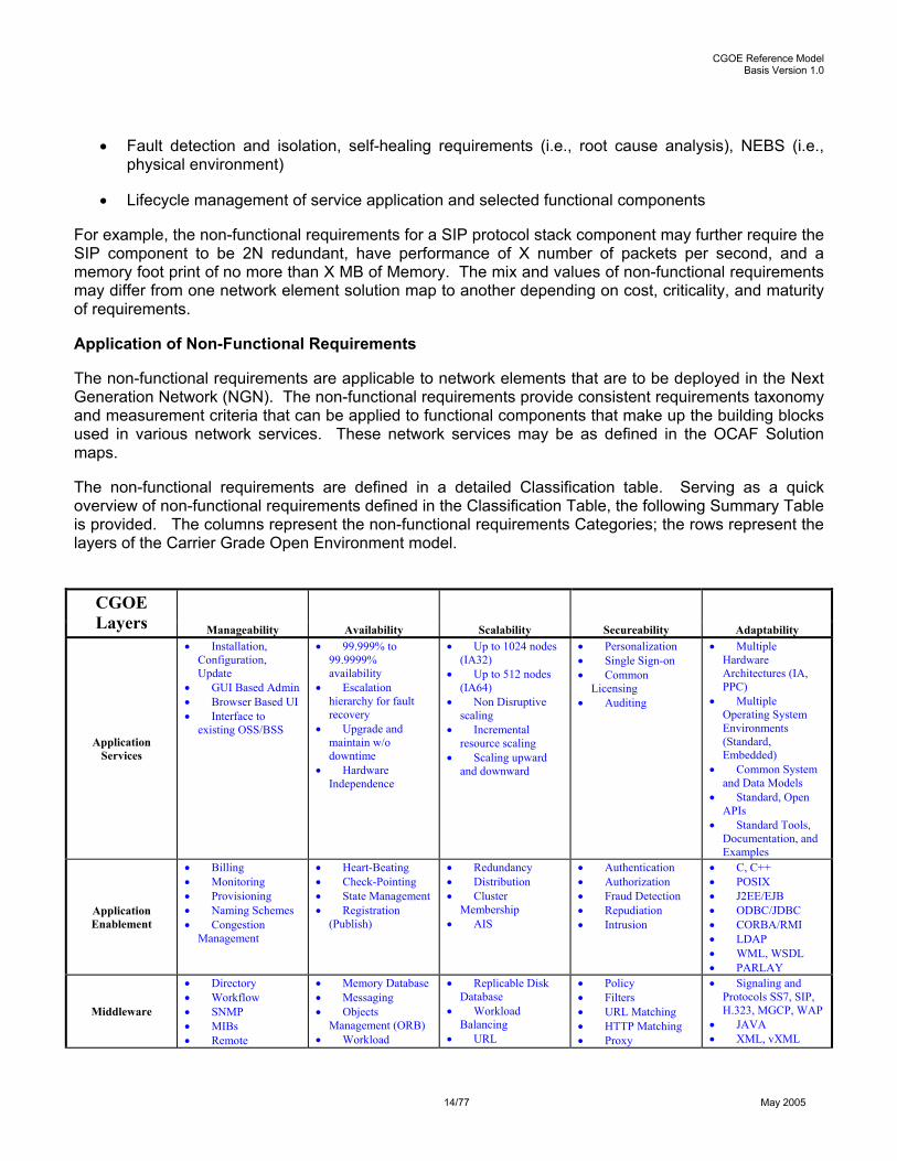
The non-functional requirements are applicable to network elements that are to be deployed in the Next Generation Network (NGN). The non-functional requirements provide consistent requirements taxonomy and measurement criteria that can be applied to functional components that make up the building blocks used in various network services. These network services may be as defined in the OCAF Solution maps.
The non-functional requirements are defined in a detailed Classification table. Serving as a quick overview of non-functional requirements defined in the Classification Table, the following Summary Table is provided. The columns represent the non-functional requirements Categories; the rows represent the layers of the Carrier Grade Open Environment model.
CGOE
Layers Manageability Availability Scalability Secureability Adaptability
Application Services
• Installation, Configuration, Update
• GUI Based Admin • Browser Based UI • Interface to
existing OSS/BSS
• 99.999% to 99.9999% availability
• Escalation hierarchy for fault recovery
• Upgrade and maintain w/o downtime
• Hardware Independence
• Up to 1024 nodes (IA32)
• Up to 512 nodes (IA64)
• Non Disruptive scaling
• Incremental resource scaling
• Scaling upward and downward
• Personalization • Single Sign-on • Common
Licensing • Auditing
• Multiple Hardware Architectures (IA, PPC)
• Multiple Operating System Environments (Standard, Embedded)
• Common System and Data Models
• Standard, Open APIs
• Standard Tools, Documentation, and Examples
Application Enablement
• Billing • Monitoring • Provisioning • Naming Schemes • Congestion
Management
• Heart-Beating • Check-Pointing • State Management • Registration
(Publish)
• Redundancy • Distribution • Cluster
Membership • AIS
• Authentication • Authorization • Fraud Detection • Repudiation • Intrusion
• C, C++ • POSIX • J2EE/EJB • ODBC/JDBC • CORBA/RMI • LDAP • WML, WSDL • PARLAY
Middleware
• Directory • Workflow • SNMP • MIBs • Remote
• Memory Database • Messaging • Objects
Management (ORB) • Workload
• Replicable Disk Database
• Workload Balancing
• URL
• Policy • Filters • URL Matching • HTTP Matching • Proxy
• Signaling and Protocols SS7, SIP, H.323, MGCP, WAP
• JAVA • XML, vXML

CGOE Reference Model Basis Version 1.0
15/77 May 2005
CGOE Layers Manageability Availability Scalability Secureability Adaptability
• Chassis Mgr • Distribution • Inventory
Management • Disk Management
Normalization • Translation TTS, STT
• SOAP, UDDI • SMTP, HTTP • RTP • RTCP
Platform Services
• Fault Notification • Trace, Dump,
Debug • Event Logging • Remote Boot
• Fault Isolation • Pre-tested and
loaded • Low Latency • Time
synchronization
• JFS • DNS • DHCP • Clustering • IPC
• Encryption • VPN • PKI • Kerberos
• QoS • SCTP
Operating System
• SNMP Traps, MIBs, and Agents
• Alarm API • Lights Out –
Remote power on/off, boot, reset, update
• BOOTP • Dprobes
• Configurable Time Slice
• Limited HDD • Real Time • Pre-emptive
• POSIX Threads • Large Main
Memory • Symmetric MP • Lightweight
processes
• SSH • ACL • IPSec
• TCP • UDP • FTP • IPv4 • IPv6
Drivers
• IPMI, UCMI • H-API • CIM
• cPCI, aTCA • Firmware / BIOS
Changes •
• ASIC • Hardware
Acceleration • Fiber Drivers • iSCSI Drivers • InfiniBand
Drivers • ATM Drivers • T1/E1 Drivers
• • Pre-Loaded SW
Server Hardware
• Alarms • Concurrent
Diagnostics • Boot Options
Changes • Bootable from
HD, FD, Net, Compact Flash, etc
• Real Time Fault Recovery, and Failover
• RS232 Mgmt port • Ethernet Mgmt
port
• NEBS / ETSI • Local Disk or
Diskless • Hot Plug PCI • Hot Swap Power,
RAM, Fans, Disk • Watch Dog Timer • Real Time Fault
Detection • Bit error
correction of memory • Virtual memory
support
• Intel/PPC/32/64 • Uni-processor • Multi-processor
2,4,8way and above • Clustering • Rack Mount
footprint density • Blade footprint
density • Maximum 600mm
W x 820mm D x 650mm H
• Network Processors
• No direct attached Keyboard, Video or Mouse
• Extended Life Cycle
Storage Hardware
• Alarms • NEBS / ETSI • Raid and
Mirroring • Arrays • Hot Swap power,
fans, disk
• Fiber Channel • iSCSI, SCSI •
• • Extended Life Cycle
Network Hardware
• Wake on LAN • NIC Bonding • Redundant cards
• Gigabit Ethernet • Fiber Channel • iSCSI, SCSI • InfiniBand • T1/E1 • ATM
• Hardware Encryption
• Extended Life Cycle

CGOE Reference Model Basis Version 1.0
16/77 May 2005
Classification Table
To aid in consistency and usability, non-functional requirements will be documented in a classification table. The non-functional requirements are classified in logical groupings generally ordered in chronological or life cycle sequence. Each non-functional requirement includes its name, description and one or more properties or standards. The requirements do not define the values of the properties, just the property name and unit of measure (IE: time, seconds).
Classification
Each of the non-functional requirements is logically placed into classifications. In general, the placements follow the principles of network element life cycle management and FCAPS.
It is possible that a non-functional requirement is listed in two or more classifications. It is also possible that two apparently similar requirements are listed in the same classification. This is the case when the context, integrity or completeness of a classification needs to be maintained.
Name
Each non-functional requirement includes a unique identifier or name that succinctly describes and distinguishes it. All attempts are made to use industry standard usage, in some cases codified in a standard.
Description
Each of the non-functional requirements include a description or definition that provides sufficient detail to be used to specify the non-functional requirement as an attribute for a managed object definition or as a system requirement.
Properties & Standards
To aid in the consistency and usability of the classification, each non-functional requirements will include one or more property or standard definitions. The classifications will not specify the values of the properties just the property name and unit of measure. In the case of a standard a document and standard reference number is included.
Non-Functional Requirements Classifications
Table 3
Ref Name (identity, group)
Description (function, properties)
Properties/Standards (value, unit of measure)
1. Manageability
1.1 Management Access
The ability for management systems external to the network element to communicate with OAM&P and management middleware resident within the network element.
SNMP, CLI, TL1, CIM, telnet, ssh, OSS/J, interactive web interface, Other (see functional requirements for specific capabilities)
1.2 System Model System Schema
The ability to store network element specific information in a predefined object CIM, MIB, XML Schema,

CGOE Reference Model Basis Version 1.0
17/77 May 2005
Non-Functional Requirements Classifications Table 3
Ref Name (identity, group)
Description (function, properties)
Properties/Standards (value, unit of measure)
oriented representation. Model typically details all managed components/resources and their relationship to other components in the network element. Information includes but is not limited to, attributes, properties, roll, methods, state, dependencies, relationships, etc.
1.3 Remote Configurability
The ability to change settings, to load data remotely expanding the functionality of an existing system for administrative aims and user provisioning. Security criteria could be adopted i.e. authentication procedure, encryption, etc.
HTTPS, FTP, XML Schema, SyncML DM, OSS/J NetConf XML protocol from IETF
1.4 Event Logging
The ability for creating and recording activities associated to customer behavior and system operational for diagnostic purpose
CLF (Common Log Format (HTTP))
1.5 Performance Monitoring
A process of collecting and analyzing data to measure the performance of a process, or activity against expected results. A defined set of indicators is constructed to regularly track the key aspects of performance. In a Telco environment, performance parameters could be i.e. IP packet loss, delay monitored usually in end-to-end scenario to evaluate possible impacts on the quality of services (service performance) provided to the customer. (ITU-T Y.1541 – Network performance objectives for IP-based service)
Dependent on type of performance being monitored.
1.6 System Management
General classification for all aspects of managing system resources and the shelf and network level.
1.6.1 Discovery
Ability to query and receive detailed information about all manageable resources/components present in target network element including both software and hardware components.
Description, location, identifier, revision, relationships, roll assignments, dependencies
1.6.2 Inventory
A detailed descriptive table maintaining information on resources discovered including both hardware and software components
Maintained in in-memory “database” or persistent storage (flash, disk, etc.) Accessible, readable, and exposable by internal management applications and

CGOE Reference Model Basis Version 1.0
18/77 May 2005
Non-Functional Requirements Classifications Table 3
Ref Name (identity, group)
Description (function, properties)
Properties/Standards (value, unit of measure)
external interfaces.
1.6.3 Roll Assignment
Ability to assign various states to individual resources/components in support of Availability Management configurations (2N, N+1, N+M, etc.). See Availability Classification.
Active, Standby, Hot Standby, Warm Standby, Cold Standby
1.6.4 Provisioning
The act of supplying a service from the submission of the requirement through the activation of service. Provisioning includes:
- User equipment, - Selection of a physical network route (i.e. the fiber, copper lines), the allocation of hardware, and engineering the connections between the hardware to form a telecommunications circuit - Enabling features for a subscriber - Allocation of processing resources
For provisioning the following attributes could be considered:
- the maximum number of transactions - the interval that the provisioning procedure will be over successful/un-successful
Support common provisioning requirements for platform and system infrastructure. e.g. A PPPoE connection provisioning involves PPPoE related functions including configuration, performance and timing etc. For provisioning of VoIP service there would be VoIP related provisioning as in PPPoE but there are requirements for certain infrastructure that are common for both such as Transaction management, Connection Numbers or Connection IDs management, System Resource Allocation, Timer Services, Events notification for status and completion, Logging and Alarms interfaces, etc. Multi-Service Switching forum has done substantial work and published IAs, see the URL below: http://www.msforum.org/techinfo/approved.shtml
1.6.5 Accounting
The collection of data for the purposes of capacity and trend analysis, cost allocation, auditing, and billing. Accounting management requires that data be measured, rated, assigned, and communicated between appropriate systems.
CDR, IPDR
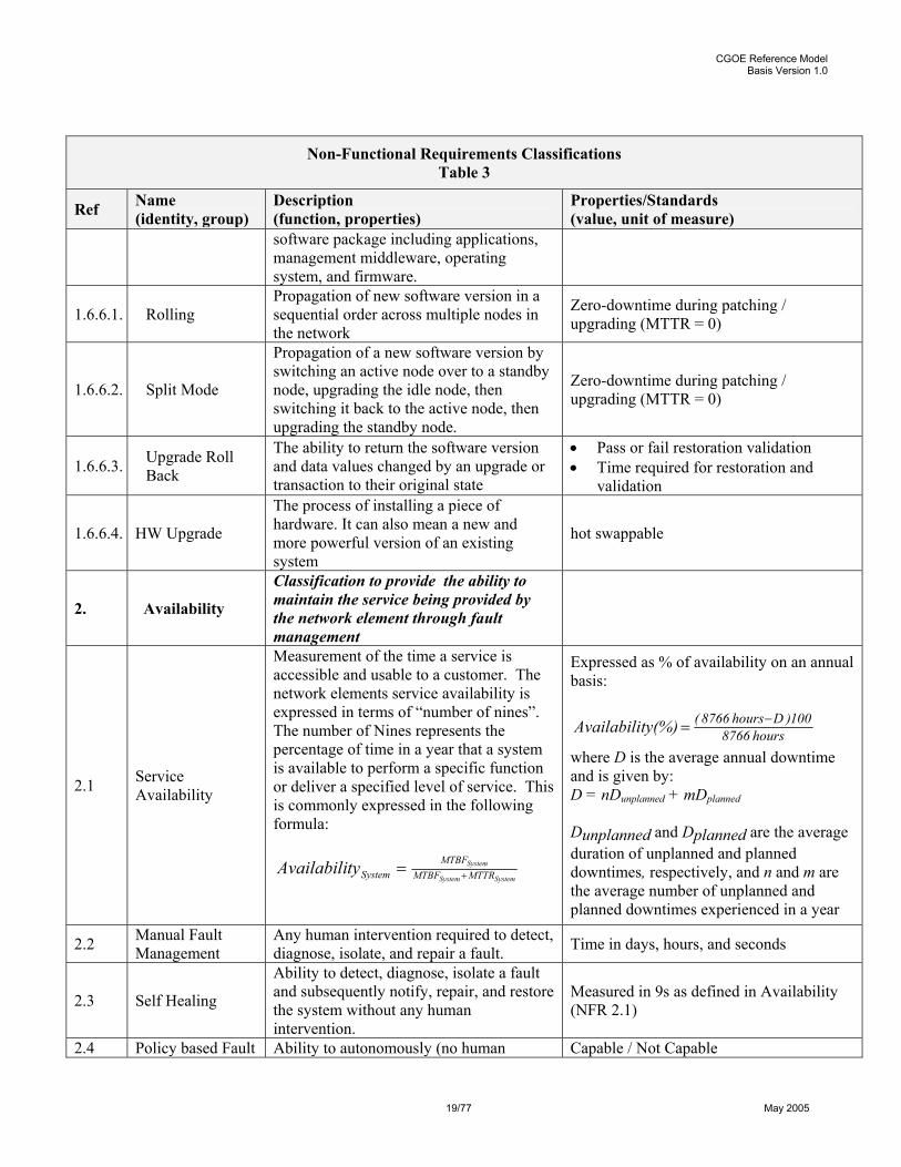
1.6.6 SW Upgrade The process of installing a bug fix, patch, or newer and more powerful version of a
Zero-downtime during patching / upgrading (MTTR = 0)
CGOE Reference Model Basis Version 1.0
19/77 May 2005
Non-Functional Requirements Classifications Table 3
Ref Name (identity, group)
Description (function, properties)
Properties/Standards (value, unit of measure)
software package including applications, management middleware, operating system, and firmware.
1.6.6.1. Rolling Propagation of new software version in a sequential order across multiple nodes in the network
Zero-downtime during patching / upgrading (MTTR = 0)
1.6.6.2. Split Mode
Propagation of a new software version by switching an active node over to a standby node, upgrading the idle node, then switching it back to the active node, then upgrading the standby node.
Zero-downtime during patching / upgrading (MTTR = 0)
1.6.6.3. Upgrade Roll Back
The ability to return the software version and data values changed by an upgrade or transaction to their original state
• Pass or fail restoration validation • Time required for restoration and
validation
1.6.6.4. HW Upgrade
The process of installing a piece of hardware. It can also mean a new and more powerful version of an existing system
hot swappable
2. Availability
Classification to provide the ability to maintain the service being provided by the network element through fault management
2.1 Service Availability
Measurement of the time a service is accessible and usable to a customer. The network elements service availability is expressed in terms of “number of nines”. The number of Nines represents the percentage of time in a year that a system is available to perform a specific function or deliver a specified level of service. This is commonly expressed in the following formula:
SystemSystem
System
MTTRMTBFMTBF
SystemtyAvailabili +=
Expressed as % of availability on an annual basis:
hours8766100)Dhours8766((%)tyAvailabili −=
where D is the average annual downtime and is given by: D = nDunplanned + mDplanned Dunplanned and Dplanned are the average duration of unplanned and planned downtimes, respectively, and n and m are the average number of unplanned and planned downtimes experienced in a year
2.2 Manual Fault Management
Any human intervention required to detect, diagnose, isolate, and repair a fault. Time in days, hours, and seconds
2.3 Self Healing
Ability to detect, diagnose, isolate a fault and subsequently notify, repair, and restore the system without any human intervention.
Measured in 9s as defined in Availability (NFR 2.1)
2.4 Policy based Fault Ability to autonomously (no human Capable / Not Capable
CGOE Reference Model Basis Version 1.0
20/77 May 2005
Non-Functional Requirements Classifications Table 3
Ref Name (identity, group)
Description (function, properties)
Properties/Standards (value, unit of measure)
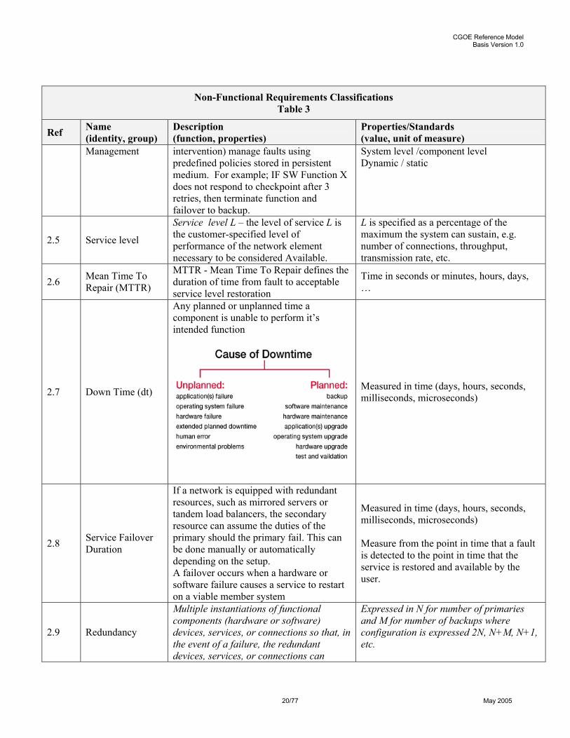
Management intervention) manage faults using predefined policies stored in persistent medium. For example; IF SW Function X does not respond to checkpoint after 3 retries, then terminate function and failover to backup.
System level /component level Dynamic / static
2.5 Service level
Service level L – the level of service L is the customer-specified level of performance of the network element necessary to be considered Available.
L is specified as a percentage of the maximum the system can sustain, e.g. number of connections, throughput, transmission rate, etc.
2.6 Mean Time To Repair (MTTR)
MTTR - Mean Time To Repair defines the duration of time from fault to acceptable service level restoration
Time in seconds or minutes, hours, days, …
2.7 Down Time (dt)
Any planned or unplanned time a component is unable to perform it’s intended function
Measured in time (days, hours, seconds, milliseconds, microseconds)
2.8 Service Failover Duration
If a network is equipped with redundant resources, such as mirrored servers or tandem load balancers, the secondary resource can assume the duties of the primary should the primary fail. This can be done manually or automatically depending on the setup. A failover occurs when a hardware or software failure causes a service to restart on a viable member system
Measured in time (days, hours, seconds, milliseconds, microseconds) Measure from the point in time that a fault is detected to the point in time that the service is restored and available by the user.
2.9 Redundancy
Multiple instantiations of functional components (hardware or software) devices, services, or connections so that, in the event of a failure, the redundant devices, services, or connections can
Expressed in N for number of primaries and M for number of backups where configuration is expressed 2N, N+M, N+1, etc.
CGOE Reference Model Basis Version 1.0
21/77 May 2005
Non-Functional Requirements Classifications Table 3
Ref Name (identity, group)
Description (function, properties)
Properties/Standards (value, unit of measure)
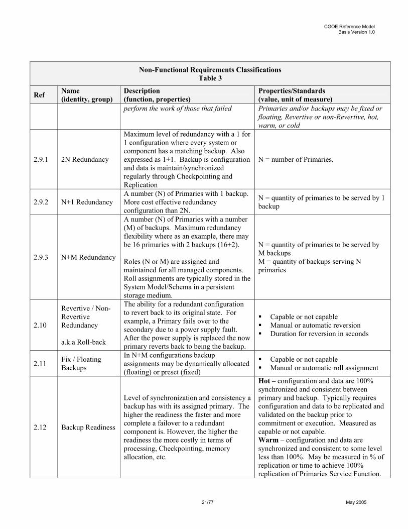
perform the work of those that failed Primaries and/or backups may be fixed or floating, Revertive or non-Revertive, hot, warm, or cold
2.9.1 2N Redundancy
Maximum level of redundancy with a 1 for 1 configuration where every system or component has a matching backup. Also expressed as 1+1. Backup is configuration and data is maintain/synchronized regularly through Checkpointing and Replication
N = number of Primaries.
2.9.2 N+1 Redundancy A number (N) of Primaries with 1 backup. More cost effective redundancy configuration than 2N.
N = quantity of primaries to be served by 1 backup
2.9.3 N+M Redundancy
A number (N) of Primaries with a number (M) of backups. Maximum redundancy flexibility where as an example, there may be 16 primaries with 2 backups (16+2). Roles (N or M) are assigned and maintained for all managed components. Roll assignments are typically stored in the System Model/Schema in a persistent storage medium.
N = quantity of primaries to be served by M backups M = quantity of backups serving N primaries
2.10
Revertive / Non-Revertive Redundancy a.k.a Roll-back
The ability for a redundant configuration to revert back to its original state. For example, a Primary fails over to the secondary due to a power supply fault. After the power supply is replaced the now primary reverts back to being the backup.
Capable or not capable Manual or automatic reversion Duration for reversion in seconds
2.11 Fix / Floating Backups
In N+M configurations backup assignments may be dynamically allocated (floating) or preset (fixed)
Capable or not capable Manual or automatic roll assignment
2.12 Backup Readiness
Level of synchronization and consistency a backup has with its assigned primary. The higher the readiness the faster and more complete a failover to a redundant component is. However, the higher the readiness the more costly in terms of processing, Checkpointing, memory allocation, etc.
Hot – configuration and data are 100% synchronized and consistent between primary and backup. Typically requires configuration and data to be replicated and validated on the backup prior to commitment or execution. Measured as capable or not capable. Warm – configuration and data are synchronized and consistent to some level less than 100%. May be measured in % of replication or time to achieve 100% replication of Primaries Service Function.
CGOE Reference Model Basis Version 1.0
22/77 May 2005
Non-Functional Requirements Classifications Table 3
Ref Name (identity, group)
Description (function, properties)
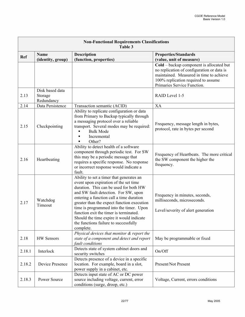
Properties/Standards (value, unit of measure) Cold – backup component is allocated but no replication of configuration or data is maintained. Measured in time to achieve 100% replication required to assume Primaries Service Function.
2.13 Disk based data Storage Redundancy
RAID Level 1-5
2.14 Data Persistence Transaction semantic (ACID) XA
2.15 Checkpointing
Ability to replicate configuration or data from Primary to Backup typically through a messaging protocol over a reliable transport. Several modes may be required: Bulk Mode Incremental Other?
Frequency, message length in bytes, protocol, rate in bytes per second
2.16 Heartbeating
Ability to detect health of a software component through periodic test. For SW this may be a periodic message that requires a specific response. No response or incorrect response would indicate a fault.
Frequency of Heartbeats. The more critical the SW component the higher the frequency.
2.17 Watchdog Timeout
Ability to set a timer that generates an event upon expiration of the set time duration. This can be used for both HW and SW fault detection. For SW, upon entering a function call a time duration greater than the expect function execution time is programmed into the timer. Upon function exit the timer is terminated. Should the time expire it would indicate the functions failure to successfully complete.
Frequency in minutes, seconds, milliseconds, microseconds. Level/severity of alert generation
2.18 HW Sensors Physical devices that monitor & report the state of a component and detect and report fault conditions
May be programmable or fixed
2.18.1 Interlock Detects state of system cabinet doors and security switches On/Off
2.18.2 Device Presence Detects presence of a device in a specific location. For example, board in a slot, power supply in a cabinet, etc.
Present/Not Present
2.18.3 Power Source Detects input state of AC or DC power source including voltage, current, error conditions (surge, droop, etc.)
Voltage, Current, errors conditions

CGOE Reference Model Basis Version 1.0
23/77 May 2005
Non-Functional Requirements Classifications Table 3
Ref Name (identity, group)
Description (function, properties)
Properties/Standards (value, unit of measure)
2.18.4 Power Supply Detects output state of AC or DC power source including voltage, current, error conditions (surge, droop, etc.)
Voltage, Current, errors conditions
2.18.5 Fans Detects state of fan including operating parameters Speed (RPMs), Current, error conditions
2.18.6 Thermal
Detect current ambient or surface temperature at sensor location. Typically numerous temp sensors are located throughout a chassis or frame/rack
Degrees F/C
2.18.7 Air Flow Detect airflow at sensor location. Typically numerous sensors are located throughout a chassis or frame/rack
Cubic Feet per minute (CFM)
2.19 Predictive Diagnostics
Ability to test current SW/HW conditions and apply results to algorithm that would indicate potential fault condition. HW example: Continuously read current levels on power supply and track to detect abnormal fluctuations. SW Example; Detect rate and level of memory consumption. In both cases generate an alert that would allow policy based management middleware to take action prior to fault condition.
Rate of change High/Low water marks Trigger levels
2.20 Fault Detection
Ability to detect and locate out of limit condition in HW or SW component and generate event/alert at appropriate level (Critical. Major. Minor)
Rate and accuracy of detection and alert once fault condition occurs. Value can be applied to MTTR calculation.
2.21 Event Generation
Ability to make known a specific event. For example; Firmware detects insertion of device into an empty slot resulting in the creation and propagation of a message and interrupt.
On/Off Filtering Frequency Queuing Severity level assignment
2.22 Alarm Generation
Ability to annunciate an event through visual or audible device. Typically through a panel located where a technician can see and/or hear the alarm.
Centralized on a Frame/Rack/Shelf/Chassis Distributed on device/board/power supply/field replaceable unit (FRU)/etc. Multi-color LEDs per Belcor standards Multi-tone audible per Belcor standards
2.23 Alarm Soaking Ability to establish a period of time (hystorisis) to allow a fault to clear itself.
Measured in minutes, seconds, millisecond, microseconds
2.24 Alarm Throttling Ability to control the number of alarms presented in a give amount of time Alarms per minute or second
2.25 Alarms Masking Ability to mask specific alarms. Capable / Not Capable

CGOE Reference Model Basis Version 1.0
24/77 May 2005
Non-Functional Requirements Classifications Table 3
Ref Name (identity, group)
Description (function, properties)
Properties/Standards (value, unit of measure)
Masking may be hierarchical in configurations where alarms are aggregated preventing low level alarms from propagating up through the system
Enabled / Disabled
2.26 Fault Masking
Ability to mask specific faults. Masking may be hierarchical in configurations where alarms are aggregated preventing low level alarms from propagating up through the system
Capable / Not Capable Enabled / Disabled
2.27 Fault Isolation
Ability to prevent a detected fault condition from propagating beyond the source. For example; excessive errors (fault) are detected on a port that is causing a buffer overflow which generated and event and alert. Good fault isolation policy would prevent connection from being switched over to another port resulting in a second fault. HW Example; power supply with excessive heat is shut down prior to causing fire or heat damage.
Fault isolation policy coverage measured in percent
2.28 Fault Analysis/ Troubleshooting
Ability to determine location and cause of a detected or predicted fault. This may or may not require human intervention. Low MTTR and high availability (9s) require automated troubleshooting capabilities.
Coverage measured in percent Automated or manual
2.29 Fault Repair
Ability to correct a detected or predicted and troubleshoot fault. This may or may not require human intervention. Low MTTR and high availability (9s) require automated troubleshooting capabilities.
Coverage measured in percent Automated or manual
2.30 Restoration Ability to assume the original state or configuration after Repair.
Duration from repair to restoration of service measured in minutes, seconds, milliseconds, micro seconds.
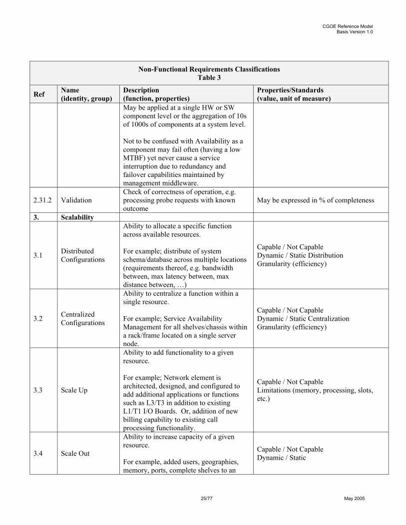
2.31 Reliability
2.31.1
Mean Time Between Failures (MTBF)
Mean Time Between Failures (MTBF) is the mean time expected between component failures in a system. MTBF determines how often the system will experience a component failure even though the component failure may not result in a system failure (depending on component redundancy).
Measured in hours and is the sum of MTTF & MTTR
CGOE Reference Model Basis Version 1.0
25/77 May 2005
Non-Functional Requirements Classifications Table 3
Ref Name (identity, group)
Description (function, properties)
Properties/Standards (value, unit of measure)
May be applied at a single HW or SW component level or the aggregation of 10s of 1000s of components at a system level. Not to be confused with Availability as a component may fail often (having a low MTBF) yet never cause a service interruption due to redundancy and failover capabilities maintained by management middleware.
2.31.2 Validation Check of correctness of operation, e.g. processing probe requests with known outcome
May be expressed in % of completeness
3. Scalability
3.1 Distributed Configurations
Ability to allocate a specific function across available resources. For example; distribute of system schema/database across multiple locations (requirements thereof, e.g. bandwidth between, max latency between, max distance between, …)
Capable / Not Capable Dynamic / Static Distribution Granularity (efficiency)
3.2 Centralized Configurations
Ability to centralize a function within a single resource. For example; Service Availability Management for all shelves/chassis within a rack/frame located on a single server node.
Capable / Not Capable Dynamic / Static Centralization Granularity (efficiency)
3.3 Scale Up
Ability to add functionality to a given resource. For example; Network element is architected, designed, and configured to add additional applications or functions such as L3/T3 in addition to existing L1/T1 I/O Boards. Or, addition of new billing capability to existing call processing functionality.
Capable / Not Capable Limitations (memory, processing, slots, etc.)
3.4 Scale Out
Ability to increase capacity of a given resource. For example, added users, geographies, memory, ports, complete shelves to an
Capable / Not Capable Dynamic / Static

CGOE Reference Model Basis Version 1.0
26/77 May 2005
Non-Functional Requirements Classifications Table 3
Ref Name (identity, group)
Description (function, properties)
Properties/Standards (value, unit of measure)
existing network element, etc. For example, methodology for scale-out, e.g. L4/7 load-balancing, proprietary load-balancing, …
3.5 Cost-curve Scaling
Min-versus-Max configuration and shape of cost-curve for scaling Cost curve in $ over time
3.6 Distributed Management
Distributed as defined above applied to management of resources including fault management
Capable / Not Capable Dynamic / Static Distribution Granularity (efficiency)
3.7 Centralized Management
Centralized as defined above applied to management of resources including man=ult management.
Capable / Not Capable Dynamic / Static Centralization Granularity (efficiency)
4. Secureability
4.1 Application layer Vulnerability
Sandbox Application, security concept (e.g. JAAS), session timeouts
4.2 OS Vulnerability Hardening of operating system
4.3 Encryption protocols SSL, IPSec
4.4 Architectural measures
Protection by packet filter / application level gateway, integration in intrusion detection
4.5 Authentication
EAP, userid/password, challenge/response, Kerberos interfacing to ADS, LDAP, NIS, PAM, Radius …
5. Adaptability
5.1 Operating System Environments
Operating Systems., e.g. Linux 2.6, HP-UX, Microsoft Windows XP, AIX, …
5.2 Operating Environments
Standardized Runtime Environments like POSIX, J2EE, J2SE, Microsoft Pocket PC Phone Edition, …
5.3 Management Middleware
Ability to use a specific revision or release of management software across different vendors of platform or platform type. For example; Vendor X’s management solution works on vendors A, B, and C platforms without modification.
5.4 System Interfaces
5.5 Platform Hardware
5.6 Interoperability
CGOE Reference Model Basis Version 1.0
27/77 May 2005
Non-Functional Requirements Classifications Table 3
Ref Name (identity, group)
Description (function, properties)
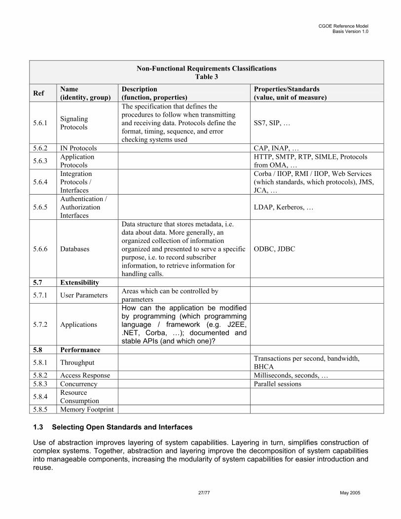
Properties/Standards (value, unit of measure)
5.6.1 Signaling Protocols
The specification that defines the procedures to follow when transmitting and receiving data. Protocols define the format, timing, sequence, and error checking systems used
SS7, SIP, …
5.6.2 IN Protocols CAP, INAP, …
5.6.3 Application Protocols HTTP, SMTP, RTP, SIMLE, Protocols
from OMA, …
5.6.4 Integration Protocols / Interfaces
Corba / IIOP, RMI / IIOP, Web Services (which standards, which protocols), JMS, JCA, …
5.6.5 Authentication / Authorization Interfaces
LDAP, Kerberos, …
5.6.6 Databases
Data structure that stores metadata, i.e. data about data. More generally, an organized collection of information organized and presented to serve a specific purpose, i.e. to record subscriber information, to retrieve information for handling calls.
ODBC, JDBC
5.7 Extensibility
5.7.1 User Parameters Areas which can be controlled by parameters
5.7.2 Applications
How can the application be modified by programming (which programming language / framework (e.g. J2EE, .NET, Corba, …); documented and stable APIs (and which one)?
5.8 Performance
5.8.1 Throughput Transactions per second, bandwidth, BHCA
5.8.2 Access Response Milliseconds, seconds, … 5.8.3 Concurrency Parallel sessions
5.8.4 Resource Consumption
5.8.5 Memory Footprint 1.3 Selecting Open Standards and Interfaces
Use of abstraction improves layering of system capabilities. Layering in turn, simplifies construction of complex systems. Together, abstraction and layering improve the decomposition of system capabilities into manageable components, increasing the modularity of system capabilities for easier introduction and reuse.
CGOE Reference Model Basis Version 1.0
28/77 May 2005
Interfaces and protocols enable communications between the system capabilities in different layers. Protocols externalize the set of capabilities in the layer along with the rules that govern access to the capabilities. Interfaces are implementations of protocol specifications by developers to enable consumption of the capabilities provided within a system layer.
Specifications for protocols are available from a variety of open standardization organizations. Examples of open standard protocol specifications are the ITU x.500 Directory Access Protocol to access the capabilities of directories for information by applications and the IETF File Transfer Protocol RFC 959 specification for access to the capabilities of exchanging files by applications.
The reference model uses open industry standards and external interfaces to assist with identification, classification, and interoperation of COTS components that satisfy the requirements of NGN services.
Open versus Closed Interfaces
Openness supports more vendors. The CGOE selection scheme emphasizes requirements for open external interfaces provided and used by COTS components. Open external interfaces are based on open standards specifications, intended for CGOE use by multiple vendors. Internal private interfaces, considered to be closed interfaces, are used only by COTS components to support vendor-specific extensions and outside scope of the CGOE.
Like versus Un-Like Interfaces
Selection emphasizes the use of similar or “like” external interfaces by COTS components to satisfy a particular set of application requirements versus the use of varying or “un-like” external interfaces by COTS components to satisfy the same particular set of application requirements.
All-IP Networking Model for NGN
The CGOE reference model is dedicated for applications in the Next Generation Network (NGN) shown in Figure 9; adheres to an All-IP networking model following standards defined by IETF; and is aligned at the networking layer to IETF for layer 3 in the OSI/ITU reference model.
The alignment to the IEEE Standards (esp. Ethernet 802.x) in CGOE is evident. The other existing protocol standards in Carrier Networks mainly defined by ITU / ATM Forum / ETSI, … are only used as physical link interfaces, in other words also here IP is the networking protocol which is transported over the existing interfaces as ISDN, ATM, GSM, SDH.
Architecture of Next Generation Networks
The NGN Network Architecture is based on the re-use of the 3GPP IMS (Release 6) for SIP-controlled services (essentially real-time conversational services). The 3GPP IMS is extended in NGN to support additional access network types, such as XDSL and WLAN. Those 3GPP IMS extensions take account of:
• The control of access networks (QoS, admission control, authentication, etc.); • The co-ordination of multiple control sub-systems to a single core transport for resource control; • The inter working and interoperability with legacy networks; • Mutual de-coupling of the application layer from the session/call control layer and the transport
layer;

CGOE Reference Model Basis Version 1.0
29/77 May 2005
• Access technology independence of session/call control layer and application layer.
For non-SIP controlled services (e.g. streaming and broadcasting) the NGN architecture may include additional service components parallel to the IMS.
Figure 9 shows a representation of the main components of the NGN.
Figure 9: Next Generation Networks - Architectural Overview
Figure 9 combines both a physical and functional overview of the scope of NGN. It makes extensive use of colour to group related aspects of service delivery. Service delivery and control are represented by components, and intend to collate related control functions. Complex services are supported in the NGN by a common applications layer.
The components are related to each other and may contain common or shared functionality. No assumptions on physical implementations should be made concerning their representation as separate
Resource and Admission Control Functionality
RACS
Based on3GPP IMS
IP ConnectivityAccess NetworkAnd related functionality
Network AttachmentFunctionality
NASS
Other Multimedia Components …Streaming Services
(RTSP based)
Applications
Core transport Network
3GPP IP-CAN
Access Transport Network
3GPP Terminals
NGN Terminals
CustomerNetworks
UserProfiles
Other N
etworks
LegacyTerminals
GW
PSTN / ISDN Emulation(SIP-I based)
IP Multimedia Component (Core IMS)
(SIP based)

CGOE Reference Model Basis Version 1.0
30/77 May 2005
components in Figure 9. Release 1 concentrates on the re-use of 3GPP specifications (orange) and the adaptation to fixed-network accesses (mid-green).
Physical transport networks provide the connectivity for all components and physically separated functions within the NGN. Transport is divided into Access Networks and Core Network, with a Border Gateway linking the two transport network categories.
The PSTN/ISDN Emulation component (fluorescent green) provides all of the network functionality associated with supporting existing services to legacy customer interfaces and equipment.
IP-connectivity is provided to the NGN customer equipment by the transport layer, under the control of the network attachment subsystem and the resource and admission control functionality.
Figure 9 represents the compilation of user and other control data into a single "User Profile" function. This function may be specified and realised as a set of co-operating databases with functionality residing in any part of the NGN.
Customer interfaces are supported by both physical and functional (control) interfaces, and both are shown in the figure. No assumptions are made about the diverse customer interfaces and customer networks that may be connected to the NGN access network. All categories of customer equipment are supported in the NGN, from single-line legacy telephones to complex corporate networks. Customer equipment may be both mobile and fixed.
The NGN interfaces other networks (such as the PSTN/ISDN, other NGN, 3GPP networks, the Public Internet, etc.) both at the control level and at the transport level, using border gateways. Border gateways may involve media transcoding and bearer adaptation. Interactions between the control and transport level may take place, directly or through the RACS functionality.
Network Attachment Subsystem (NASS)
The NASS provides registration at access level and initialization of Customer Premises Equipment (CPE) for accessing the TISPAN NGN services. It also provides network level identification/authentication, manages the IP address space of the Access Network and authenticates access sessions. In addition, the NASS announces the contact point of the TISPAN NGN Service/Applications Subsystems to the CPE.
Network attachment through NASS is based on implicit or explicit user identity and authentication credentials stored in the NASS.
Resource and Admission Control Subsystem (RACS)
The RACS provides admission control and gate control functionalities (including the control of NAPT and priority marking). Admission control involves checking authorization based on user profiles held in the access network attachment subsystem, on operator specific policy rules and on resource availability. Checking resource availability implies that the admission control function verifies whether the requested bandwidth is compatible with both the subscribed bandwidth and the amount of bandwidth already used by the same user on the same access, and possibly other users sharing the same resources.
RACS services can also be offered directly to Application Functions that may reside in different administrative domains.

CGOE Reference Model Basis Version 1.0
31/77 May 2005
PSTN/ISDN Emulation (PES)
The NGN will support a gradual migration for the support of both legacy equipment and the PSTN/ISDN service set. Key scenarios of this feature are:
• PSTN/ISDN Replacement (in whole or in part) • Support for legacy terminal equipment connected directly and indirectly to the NGN.
Here, legacy terminal support includes direct connection via an SCN access network and indirect connection via terminal adaptation and the broadband access network.
It is essential that the PSTN/ISDN service set and call servers are not re-defined by NGN. It is assumed that a PSTN/ISDN call server will provide an ISUP or other PSTN call model, and will provide signalling transport and interworking.
The "Core" IP Multimedia Subsystem (IMS)
The IP Multimedia Subsystem (IMS) core component of the NGN architecture (Core IMS) supports the provision of SIP-based multimedia services to NGN terminals. This includes the provision of so-called PSTN/ISDN simulation services, which model the behaviour of classical ISDN/PSTN services in the NGN. Such a model is not expected to be perfect, and in particular full service interworking with the ISDN/PSTN is not required. For an exact replication of the legacy services to legacy terminals, a dedicated subsystem (the Emulation subsystem) exists.
Further subsystems
In future releases, the introduction of additional service components is envisaged. Two candidates are:
• A Streaming Subsystem to support the provision of RTSP-based streaming services to NGN terminals.
• A Content Broadcasting Subsystem to support the broadcasting of multimedia content (e.g. movies, TV channels etc.) to groups of NGN terminals.
Common components
The NGN architecture includes a number of functional entitles that can be accessed by more than one subsystem. These are:
• User Profile Server Function (UPSF); • Subscription Locator Function (SLF); • Application Server Function (ASF); • Interworking Function (IWF); • Interconnection Border Control Function (IBCF); and • Charging and Data Collection Functions.
Further information

CGOE Reference Model Basis Version 1.0
32/77 May 2005
More detailed documentation on the NGN architecture and its components can be found in the relevant ETSI drafts:
• ETSI TS 282 001: "TISPAN NGN functional Architecture". • ETSI TS 282 002: "TISPAN PSTN/ISDN Emulation Subsystem". • ETSI TS 282 003: "TISPAN Resource and Admission Control Subsystem". • ETSI TS 282 004: "TISPAN Network Attachment Subsystem". • ETSI TS 282 007: "TISPAN IP Multimedia Subsystem core component".
IP Protocol Stacks
The alignment to W3C standards (e.g. HTML, XML) is consequently also trivial. Therefore the protocol services for the NGN applications are either W3C standards (as XML, HTML,) or IETF defined protocol services e.g. SIP based IP Multimedia Subsystem or SIP based PSTN/ ISDN emulation services or streaming based services (RTSP: Real Time Streaming Protocol). The alignment of the protocol standards is illustrated in Figure 10.
Figure 10: Alignment of Protocols
IETF/ IEEE/ ITU/ATMF/ W3C Alignment (Protocols)
html xml xsl smil
802.2
802.3 802.4 802.5 802.11
HTTP FTP SMTP DNS SNMP
SDH GSMATMISDN
NFS
UDP
IP-EPPP ARP
W3C
IETF
ITUETSIATMF
SCTP
M3UA
IP
Internet
wwwApplication
Transport
Network
Link
Physical 802.16
…
TCP …
….html xml xsl smil
802.2
802.3 802.4 802.5 802.11
HTTP FTP SMTP DNS SNMP
SDH GSMATMISDN
NFS
UDP
IP-EPPP ARP
W3C
IETF
ITUETSIATMF
SCTP
M3UA
IP
Internet
wwwApplication
Transport
Network
Link
Physical 802.16
…
TCP …
….
CGOE Reference Model Basis Version 1.0
33/77 May 2005
1.4 Selecting Properties, Relationships, and Boundaries
Using the principles described in this section 1 of this document, the CGOE defines a framework of standards for COTS components (as defined in Appendix B – Glossary of Terms). Each COTS component is defined by:
• A category which ties it to the CGOE Reference Model.
• Programmatic interfaces used and exported. These interfaces are the subject of existing standards or they identify gaps in the set of relevant existing standards.
• Internal functional properties which describe what a component does beyond that which the interfaces describe. These properties may also be the subject of standards or gaps in standards.
• Non-functional properties. These are properties that are expected to be documented by the provider of a component instance (as defined in Appendix B – Glossary of Terms).
The network of interfaces to these components defines the relationships between the components. The sum of these interfaces is the framework of standards described by the CGOE.
Within this framework there are two categories of interfaces: Those which are intended to be used by the Application (see Appendix B – Glossary of Terms) as well as other components, and those which are intended to be used only by other components.
The framework can be viewed at several levels of scale or detail. At the least detailed level, Figure 6 categorizes the components technology usage and basic function. At the most detailed level each individual component can be examined with each interface, functional property, and non-functional property exposed. The later level of detail is out of scope for this document but may become available separately by OCAF.
At an intermediate level, Figure 11shows an interface-oriented view of the categories and places the components into these categories. [This should note that the set of components presented is evolving and only represents those which have been discovered by completion of a study team exercise!] This diagram only exposes the major interfaces (which fall into the first category defined above) and hides the interfaces used by components within a category, as well as all interactions with the operating system and lower layers. It also does not present the external non-programmatic interfaces (like protocols).
This intermediate level of definition can be used to navigate the CGOE. For example, consider the “OAM&P Middleware” component:
• It uses the “requests” interface of the “HTTP” component. You would refer to detailed the HTTP component description to understand this programmatic interface, the external interactions, etc.
• It abstracts the variety of access mechanisms (HTTP, FTP, SNMP) and presents a “query” interface to other CGOE components and to the application. You would refer to the detailed OAM&P Middleware component description to understand how this is done.
Figure 11is a (mostly) technology independent representation of the CGOE. The programmatic interfaces could be expressed in any computer language (JAVA or C++ for example). The detailed component descriptions reference standards for specific instances of these interfaces.

CGOE Reference Model Basis Version 1.0
34/77 May 2005
Figure 11: Boundaries and Relationships
<<Category>>Basic Network Appl Services
SubscriberProfileManager
<<Category>>Protocol Services
Diameter
<<Category>>Base IP Services
NTP HTTPFTP SNMP
<<Category>>Platform Event Services
EventManagment
LogManagement
<<Category>>OAM&P Middleware
OAM&PMiddleware
<<Category>>Data Model Services
DataModel
<<Category>>Database Middleware
DatabaseMiddleware
<<Category>>
Application
<<Category>>Workload Management Services
LoadBalancer
OverloadControl
Performance
Monitoring
<<Category>>Signalling Protocol Stacks
SIP
<<Category>>
Security
<<Category>>High Availability Services
AvailabilityManager
SWResource Manager
DiagnosisAlarmManager
HW Resource Manager
SQL IF
SQL IF
Rp IF ( as defined in 3GPP)
Query IF
Platform Services
Middleware
Application Services
Application
AAA IF
Event IF
Log IFPolicy IF
Operations Commands Requests
SIP IF
To - High Availability & Workload MgmtServices
To –High Availability Services
Workload IF
<<Category>>System Model Services
PolicyManager
SystemModel
SWUpgrade
Patching
SW-Upgrade IF
ConfigManager
<<Category>>Basic Network Appl Services
SubscriberProfileManager
<<Category>>Protocol Services
Diameter
<<Category>>Protocol Services
Diameter
<<Category>>Base IP Services
NTP HTTPFTP SNMP
<<Category>>Platform Event Services
EventManagment
LogManagement
<<Category>>Platform Event Services
EventManagment
LogManagement
<<Category>>OAM&P Middleware
OAM&PMiddleware
<<Category>>OAM&P Middleware
OAM&PMiddleware
<<Category>>Data Model Services
DataModel
<<Category>>Data Model Services
DataModel
<<Category>>Database Middleware
DatabaseMiddleware
<<Category>>Database Middleware
DatabaseMiddleware
<<Category>>
Application
<<Category>>Workload Management Services
LoadBalancer
OverloadControl
Performance
Monitoring
<<Category>>Workload Management Services
LoadBalancer
OverloadControl
Performance
Monitoring
<<Category>>Signalling Protocol Stacks
SIP
<<Category>>Signalling Protocol Stacks
SIP
<<Category>>
Security
<<Category>>High Availability Services<<Category>>High Availability Services
AvailabilityManagerAvailabilityManager
SWResource Manager
SWResource Manager
DiagnosisDiagnosisAlarmManagerAlarmManager
HW Resource Manager
HW Resource Manager
SQL IF
SQL IF
Rp IF ( as defined in 3GPP)
Query IF
Platform Services
Middleware
Application Services
Application
AAA IF
Event IF
Log IFPolicy IF
Operations Commands Requests
SIP IF
To - High Availability & Workload MgmtServices
To –High Availability Services
Workload IF
<<Category>>System Model Services
PolicyManager
SystemModel
SWUpgrade
Patching
SW-Upgrade IF
ConfigManager
<<Category>>System Model Services
PolicyManager
SystemModel
SWUpgrade
Patching
SW-Upgrade IF
ConfigManagerConfigManager

CGOE Reference Model Basis Version 1.0
35/77 May 2005
2 DESCRIPTION OF COTS COMPONENT LAYERS AND CATEGORIES
2.1 Server Hardware
A grouping of CGOE layers that can be used in several industries with minimal modification and includes physical hardware and the drivers needed to use that hardware. While CGOE is hardware-agnostic, some requirements need to be met by both hardware and drivers to enable carrier grade operation.
Hardware Layer
CGOE covers a variety of hardware platforms, given the capabilities to meet the necessary carrier grade requirements exist on the selected platform. It must be recognized that some hardware capabilities can be modified or waived in situations where a solution has service level agreements that can tolerate their absence.
Drivers Layer
Drivers are essential to CGOE for enabling support of plug-gable carrier grade hardware and software components. The vendors of hardware components are expected to make drivers available for their components.
Any driver that is to be used the hardware should go through specific device driver hardening that is typical of carrier grade enhancements which are further discussed in the section on Operating System layer.
2.2 Base Operating Platform
A grouping of CGOE layers that includes the basic operating system with processor scheduling, I/O subsystems, interfaces to other hardware components, etc…
Services reside in this configuration for high availability and internal messaging capabilities, as well as components that enable scalability and manageability using carrier grade-enhanced OS (or standard OS for less restrictive service levels).
Operating System Layer
The operating system layer is the software foundation upon which the rest of CGOE is built. As such, it must provide the solid basis that is extended by components of other CGOE layers. The criterion for selecting the operating system for CGOE has much to do with the “openness” of the operating system. Such selection as a result, may cause some stringent requirements to be placed on that specific OS for supporting specific open standards like POSIX.
In addition to openness, CGOE requires the use of any necessary carrier grade OS capabilities. For example, the Carrier Grade Linux Working Group of OSDL took the lead in establishing the functional characteristics of the Linux operating system to allow it to provide an open platform upon which carrier operations can be successfully conducted. These functional characteristics are appropriately termed "carrier grade enhancements".
CGOE does not define Carrier Grade Linux as the preferred operating system, but when Linux is chosen to satisfy requirements for CGOE OS layer, the compliance to Linux Standards Base is recommended.

CGOE Reference Model Basis Version 1.0
36/77 May 2005
Base IP Communications
Basic IP communications protocols used for CGOE are expected to typically reside within the operating system. For CGOE, significant examples of these protocols are:
• TCP, UDP, IPv4, IPv6, IPSec, PPP, ARP, FTP, DNS, NFS, RTP, RTCP, SSL, …
All of these protocols are defined by IETF and W3C. Additional protocols that may be included here are HTTP, SMTP, and SNMP, depending upon the OS chosen for CGOE.
Platform Services Layer
The Platform Services layer includes high availability and internal messaging capabilities, as well as components that enable scalability and manageability. Workload, remote interfaces, system model, data model, and Java services are included.
High Availability Services
High availability services enable CGOE to provide a highly available operating environments. Taken in the context of carrier grade, these are environments whose availability ratio can be as high as between 99.999% and 99.9999% (five to six nines) for a specific measure of time (typically one year).
The current approach at high availability is that it needs to be built into the system as well as the individual applications. To meet the highest availability requirements, applications need to be specifically designed for high availability.
High availability services are based on the philosophy of making software services reliable on the hardware and software platforms under the most adverse conditions. Redundant hardware resources are thus used, services are divided to active and standby instances or load sharing groups, and application software actively contributes to availability. High availability services also provide supervision and recovery functionality for service instances.
High availability services provide the following:
• Starter Service – Starts the application processes within a node. The operating system will start the high availability services when the node boots and high availability services will start all other processes.
• Graceful Shutdown Service – HA-aware applications are notified upon operator requests to shut down the system and are allowed to wrap up and terminate themselves "as gracefully as possible" within a certain period of time defined either by a platform configuration parameter or by the operator. All HA-aware applications should be prepared to handle this situation. This graceful shutdown service is provided in addition to the OS shutdown notification facility for a better synchronization and life cycle management of all the resources belonging to the cluster.
• Supervision – A fault detection mechanism. Two types of supervision are performed: application supervision and node supervision.
• Communication Support – Handles IP address recovery units and check pointing.
CGOE Reference Model Basis Version 1.0
37/77 May 2005
• System State Management Service – Maintains permanent and transient state for the managed objects it is aware of. Permanent state is persisted in permanent storage and is thus preserved in the event of cluster restarts. In contrast, transient state is lost in case of a system restart.
• Failure Detection, Isolation, Recovery and Repair Services – These services supervise the nodes, the communication networks and the application processes. They are able to detect failure in these resources. They isolate nodes or recovery units in case of failure and initiate recovery either by using reconfiguration (software switchover) or restarting. Change of faulty hardware can be done while the system is running on spare nodes.
CGOE takes advantage of the specifications for high availability services defined by the Service Availability Forum (SAF), where applicable. The interfaces and components in CGOE are required to be SAF compliant where appropriate. The OCAF six-step process will determine if SAF compliance is required based upon how SAF compliance is defined for a particular building block.
Cluster Messaging Services
CGOE high availability services described above have a strong dependency on a reliable cluster messaging. In order to successfully provide any of the described services, communication between the different systems or nodes and software running on the said nodes must be done reliably and without delays. A strong messaging subsystem will ensure that messages are delivered accurately to the destination nodes. Many possibilities exist for the implementation of a messaging subsystem, e.g. CORBA messaging, RMI, standard TCP/IP messaging, etc…
It can be thus said then that a reliable, accurate and high performance messaging subsystem is at the heart of the high availability services. Consequently, SAF will define the resulting requirements of the messaging services.
Workload Management Services
Workload management services in CGOE are essential for carrier grade operations for the handling of overload situations and for balancing the load of a processing cluster. Thus, workload management services are divided into two groups of functions:
• Overload Control Functions that ensure the system does not loose its service availability even under an overload situation.
• Load Balancing Functions that take care of IP level, transport level, and application level load balancing.
Application level load balancing of the operating environment needs to support different load balancing algorithms, and needs to be application protocol-aware in case the load balancing algorithm is tightly coupled with the application. The algorithm for load balancing may also need to be application protocol aware when the serving nodes in a cluster are required to support different application protocols.
The application level load balancer for CGOE does the following:
• Selects the service instance of the cluster offering service for a certain session.
• Supports a variety of application protocols.

CGOE Reference Model Basis Version 1.0
38/77 May 2005
• Hides the internal structure of the cluster and hides the scaling of the cluster.
The application level load balancer needs to be able to analyze the application level protocol in case it needs to encrypt the application protocol and act as a layer 7 switch.
There may be a current standards gap for Workload Management Services since no standards are readily identifiable for this category.
Remote API Services
Remote API services provide CGOE with the means for distributed objects communication and execution. Remote API services are to provide location transparency, independence of interface definition from implementation, networking protocols, computing platform and programming language independence.
CGOE does not call out a specific middleware to provide this functionality even though CORBA is recognized as a well-known standard architecture able to provide the required remote API functionality and is indeed widely used in the telecommunications industry. RMI/IIOP (for Java based applications) and SOAP can also provide suitable capabilities to fulfill the requirements of remote APIs. CGOE advocates using these services to minimize the interoperability problems between different middleware solutions requiring remote API services.
In the case CORBA is used, for example, it would be necessary that the following functional characteristics be met for CGOE:
• Object Request Broker (ORB) to access the services
• Notification service to enable asynchronous messaging
• Naming service to locate objects by using logical names
• Logging services to give developers and test engineers a way capture significant system events and be able to trace and debug problems.
Interfaces of CGOE are preferably defined with an Interface Definition Language (IDL), e.g. WSDL for Web Services.
System Model Services
The System Model Services for CGOE provide ways to access and use the managed objects of the system defined by the system model.
The system model services support activities such as:
• Installation
• Configuration
• Update
• Monitor
CGOE Reference Model Basis Version 1.0
39/77 May 2005
• Life cycle management
The above activities occur in reference to the platform resources associated with service instances defined through the CGOE system model.
This portion of CGOE provides the means for easier applications management (i.e. non-disruptive installation and update). It provides scalable management model and integrates the existing management solutions. The OAM&P artifacts can administrate the system model objects contained in the system model portion. This topic is also an important SAF focus, therefore a reference to the SAF activities should be added and become a joint SAF/OCAF task.
Data Model Services
This portion of CGOE provides ways to access and use the well-known data schemas required by the system. The aim is to provide an abstraction level that allows the interoperation and substitution of different data management solutions on the platform.
This includes, for example:
• System Model Data schemas
• Provisioning data schemas
• Configuration data schemas
• System API definitions
• Functions to update, create and delete the schemas
The schemas can be defined with XML, RDD, LDAP and other suitable tools.
Platform Event Services
This portion of CGOE provides services for managing events and logs.
Java Services
This portion of CGOE provides basic Java run time services when full J2EE web services would not be needed.
It includes for example:
• Runtimes and APIs for running applets and applications written with Java
• Essential compiler, tools for writing, deploying, and running applets and applications in the Java programming language.
CGOE advocates the use of a common Java Virtual Machine for both J2EE and Java Stand-alone applications and services. Java is depicted at this layer in the diagram to show that in some server

CGOE Reference Model Basis Version 1.0
40/77 May 2005
deployments a full J2EE server may not be required but in fact may be installed to provide the common JVM for stand-alone use.
2.3 Extended Operating Platform
A grouping of CGOE layers that include databases, protocols, management, web services and proxies to enable the application layer and extend the base operating platform. Abstraction of services for middleware is included for easier access and use by application developers. “Application services” also add value to the basic functions provided by the middleware by combining and chaining the services with logic suitable for the application developers.
Middleware Layer
The Middleware Layer for CGOE includes additional specific software for databases, protocols, OAM&P, and J2EE.
Signaling Protocol Stacks
Signaling protocol stacks contain those carrier grade enhanced protocols that are needed for controlling the services on the network. The protocols included in CGOE are such that they are used in several network elements in a network configuration.
These include for example:
• SIGTRAN
• SIP
• Diameter
• COPS
• Megaco / H.248
• MGCP
• BGP
These protocols are IP-based but non-IP based protocols such as Signaling System 7 can also be introduced if there are suitable interfaces in the hardware configuration. Other protocols than listed above can be used but only protocol stacks that fulfill a specific application need to be chosen for CGOE.
Gateway Protocol Stacks
Gateway protocols are the payload counterpart of the signaling protocols, i.e. used for transferring user data. These protocols are such that they are naturally used in several network elements in a network infrastructure.
These include for example:
• SCTP

CGOE Reference Model Basis Version 1.0
41/77 May 2005
• RTP
These protocols are IP-based but non-IP based protocols can also be introduced if there are suitable interfaces in the hardware configuration. Other protocols than listed above can be used but only protocol stacks that fulfill a specific application need to be chosen for CGOE.
Interface and Service Proxies
This portion of CGOE provides the core of the distributed programming model by brokering and mediating the APIs between clients and servers.
It provides an access point for application servers and applications by:
• Distributing new sessions to appropriate registered application / applications servers.
• Managing Session Affinity between Applications and Services Servers.
• Responding to managed shutdowns of application and services capability server
This portion of CGOE participates in the system start up. It also defines the Client/Server responsibilities with respect to high availability, security and service discovery.
OAM&P Middleware
The Operation, Maintenance, Administration and Provisioning (OAM&P) middleware provides the means to reach the objects defined by the system model via the system model services. OAM&P middleware features provide easy and efficient ways to create operable applications on the network elements. One of the prime objectives for an operator/service provided in this area is to make sure that all services are highly operational i.e. service assurance2 is achieved.
The OAM&P middleware is the external view of the system model and services. It externalizes the usage, performance, and execution of the services.
For example, it provides (in many instances in collaboration with the portal services) the tools to create user interfaces as well as management and provisioning interfaces for activities such as:
• Installation
• Configuration
• Update
2 Service assurance is another important context. It consists in the monitoring of the services. This means that the health of the service is monitored (errors, alerts, etc.), usage tests (use measurements, resource utilization, etc.) are run when Customer Service Representatives (CSRs) report unusual customer exceptions in areas like service usage (e.g. PIN numbers are not working/valid), and emergencies are handled when CSRs are not available (after normal working hours).
CGOE Reference Model Basis Version 1.0
42/77 May 2005
• Monitoring
• Life cycle management
• Billing, Accounting and Charging
The above activities occur in reference to the platform resources associated with service instances, defined through the system model.
These tools include, for example:
• Aids For Configuration Management – Include hardware and software configuration management, parameter management, and bulk configuration aids.
• Aids For Performance Management – Include efficient tools for monitoring and troubleshooting the network element performance from an operator’s perspective.
• Aids For Statistics Collection – Entails information collection for monitoring of the network element performance from an operator’s perspective. The information collected can be used to support the operation of the network element, analyze its operability and performance, and pinpoint possible problems and bottlenecks.
• The OAM&P middleware features are essential when driving the total cost of ownership down, and when maintaining the serviceability of a system.
Editorial Note: FCAPS will be added and aligned to TMF with a reference to the open standards section in future version(Max Bornschlegl).
Database Middleware
The database middleware provides the CGOE carrier grade environment for storing the data defined by the data model services. Several data management providers and solutions may be utilized depending on the needs of the server being defined on the platform. The database Middleware has to support all de facto standards e.g. ODBC, JDBC.
Both in-memory and disk databases together with directories can coexist on a platform implementing CGOE. There can be a convergence from in-memory databases to disk databases if disk databases meet the performance requirements of specified applications.
J2EE/ Web Services Middleware
J2EE (Java 2 Platform Enterprise Edition) provides CGOE with a simplified application development model and enjoys, if needed, the benefits of a thin client tiered environment. It has also built-in capabilities to interface with CORBA.
It includes, for example:
• Java Messaging Service
• Java Mail

CGOE Reference Model Basis Version 1.0
43/77 May 2005
• Servlets
• JSPs
• EJBs
• Rich connector architecture
• HTTP
These specifications place a requirement for a robust application server with containers that are streamlined to be able to provide the highest qualities of service with the proper constructs for availability and serviceability. While OCAF expects Java and Web Services will play a dominant role, other dominant (existing) interfaces, if open, may be included (e.g. C++ and .NET/C#).
Applications Services Layer
The “application services” abstracts the services provided by the middleware layer to the application layer. “Application services” also add value to the basic functions provided by the middleware by combining and chaining the services with logic suitable for the application developers.
Protocol Application Services
This portion of CGOE provides added value for the application developers by hiding the complexity of multiple protocol stacks and by adding the abstraction of the protocol service access. Its functionality includes but is not limited to:
• Accessing the protocols for telecommunications purposes
• Combining primitives from several stacks to aid application development
• Providing an abstracted interface to protocols to aid application development
• Enables differentiation according to the specific NGN layer and application layer
OAM&P Application Services
This portion of CGOE provides added value for the application developers by abstracting the OAM&P middleware to provide easy development of OAM&P applications.
It abstracts the services of OAM&P middleware across different OAM&P middleware implementations and links separate solutions with specific sets of APIs based on the supported standard management models (e.g. CIM, WEBM, WSDM),
Basic Networking Application Services
This portion of CGOE provides added value for the application developers by abstracting the platform to aid the development of networking applications, and by providing a set of generic networking services such as:
• Accessing the database for networking purposes

CGOE Reference Model Basis Version 1.0
44/77 May 2005
• Supporting the state machine based development paradigm
• Defining the network addressing models (e.g. E.164/ENUM)
• Defining the network analysis models (e.g. address & route analysis)
These services abstract the specifics of the implementation of any facility put in place to serve a vendor-specific network application and allow a degree of plug ability to support the NGN Network Model. The goal here is to be able to switch with a fair degree of success and ease from one vendor to the other.
Portal Services
This portion of CGOE provides consistent, efficient and intuitive means to provide Web-based end user interfaces for different end user equipments such as phones or PDAs.
Some outlined uses are:
• Developing applets
• Developing portlets
• Customizing web pages
Portal services provide a rich set of functions and interfaces that will be available on all the devices that will access the services. For example the services developers will only have to write the services once and portal services will ensure that the proper interface is presented to the user depending on the device that is being used to access the services.
Not only will the portal services provide a consistent access across all the services, they will also allow collaboration between users, providing a habitat or a virtual workplace where the features are utilized to their fullest potentiality and while providing a rewarding user experience.
CGOE encourages the interfacing of the portal services to other subscriber and operator-facing services for the creation of user interfaces that provide better usability, improved intuitiveness and aesthetics that will ultimately result in tremendous savings of time and resources.
It is desirable that the development environment provide the ability to migrate existing applications to a portal environment be provided to CGOE adopters. This allows for ease and speed of the creation of new services and the extensions of existing services to a wider range of clients and devices.
2.4 Industry Application
This is the top layer of the CGOE reference model. Solution specific application logic is located in this layer that uses services of the other layers. Network applications in the telecom domain can be divided into control plane, management plane and service plane solutions.
These specifications do not prescribe what applications to write. The possibilities are indeed infinite. Therefore, the activity of specifying COTS components for the end user applications to be written is out of the scope of CGOE. Only an overview of some types of applications likely to be written can be provided.

CGOE Reference Model Basis Version 1.0
45/77 May 2005
Control Plane Applications
The control of network resources to establish connectivity between subscribers and network services is done by the control plane applications. Typical control plane applications or solutions are products like a Call Processing Server, a Radio Network Access Servers, etc. "Five to six nines" service availability and high scalability are strict requirements for control plane solutions.
Management Plane Applications
Carrier grade networks need to be highly manageable. They need to provide high levels of security to the user traffic. They also need to help minimize the cost of ownership. Network management applications such as network development, optimization, monitoring, reporting, and administration are the prime applications targeted at the management plane. Service availability requirements are in the class of “five nines”. Scalability requirements in the management plane are relatively modest when compared to the control plane requirements.
Service Plane Applications
Extra services on top of the connectivity network are created by the service plane applications. The number of applications requiring the services of an application server is on a steadily and rapidly increasing path. Solutions in current networks include but are not limited to: Short Message Service Center, WAP Gateway, Content Delivery Servers, Serving Mobile Location Center, Presence Server, Download Server, Web Server access point, and portals.
Independent service vendor (ISV) solutions run on the service plane. Service availability and scalability requirements vary a great deal in this plane. That depends on the solution area, business case and SLAs currently in place.

CGOE Reference Model Basis Version 1.0
46/77 May 2005
3 DESCRIPTION OF APPLICABLE COTS COMPONENTS
Editor Note: More components and additional component details will be provided in future versions by study team(s) (Johannes Prade)
3.1 Basic Network Application Services
Subscriber Profile Manager
tbd
3.2 Protocol Services
Diameter
A Diameter base protocol is a component that operates as an interface. It provides an Authentication, Authorization and Accounting (AAA) framework for applications such as network access or IP mobility. New technologies such as wireless, DSL, Mobile IP and Ethernet, and the increased complexity and density of routers and network access servers have put new demands on the protocol that are not met by former authentication, authorization and accounting protocols like Radius and TACACS.
The component Diameter acts as a server, which provides a concrete AAA facility. Diameter is used as base protocol for the following IMS interfaces:
• Cx
• Sh
Diameter offers the capability for authentication, authorization and accounting.
3.3 Signaling Protocol Stacks
Session Initiation Protocol
The Session Initiation Protocol (SIP) is an application-layer signaling protocol that allows for the creation, modification, and termination of session between participants. Typical sessions include telephone calls, conferencing, multimedia exchanges, and instant messaging and chat. The SIP protocol defines a clear separation between the control mechanism and the mechanics of the communication. Descriptions of session mechanics are deferred to other protocol standards, such as the Session Description Protocol (SDP). Consequently, SIP can be used as a control protocol for a wide range of applications.
SIP defines a number of SIP elements that can be used for request routing, authentication, and the construction of complex services. SIP contains a notion of device registration, where user devices register their contact specifics, capabilities, and user contact preferences with a SIP registrar under a public address. When setting up calls, a SIP call control application consults the registrar to determine how to connect a call. Additional components such as service brokers may be used to provide additional abstraction and support for complex service logic. Requests are routed to end destination networks based on the domain name in SIP addresses, where an individual SIP address is known as SIP URI. Communication between SIP elements makes use of UDP, TCP, and TLS (via SSL) transports for message exchange.

CGOE Reference Model Basis Version 1.0
47/77 May 2005
The SIP protocol stack provides an API for implementing a SIP user agent (UA). Since a SIP UA may sometimes act as client and sometimes as server, a SIP application must be able to handle continuous asynchronous processing of SIP messages throughout the lifetime of a communication session. The protocol stack API should provide some enforcement of proper SIP transactional semantics, keeping the application compliant with the SIP specification. Higher level APIs and SIP services may be offered to the application through a SIP application server, which extends the SIP protocol stack concept to provide an extended runtime environment for SIP application logic.
SIP protocol stacks must be able to scale according to message traffic and call volumes. SIP protocol stack components should support a horizontally scalability scheme, where incoming calls can be routed to least loaded servers. Implementation of this scheme typically requires a three tier model, where a front IP load balancer distributes load for initial requests to a second tier of SIP stateless proxies that perform SIP-level load balancing. The SIP stateless proxies pick a least loaded SIP protocol stack instance and ensure that future messages within that session are routed to the same instance.
3.4 OAM&P Middleware
OAM&P Middleware is a component and an optional interface that provides an abstract software layer that shall be used by any software, especially by other CGOE components, in modeling its managed objects independently of the query interface / language. It provides a “neutral” modeling technique and maps this to the appropriate or required OAM&P interface, e.g. SNMP, http, XML, etc. The OAM&P middleware runs as a server offering the advantage, the abstract software layer is available at runtime.
OAM&P middleware offers the capability for abstraction layer support with a technology independent Query interface. This is the primary interface for OAM&P Middleware.
The component OAM&P middleware includes at least the following classes of subcomponents:
• Application Programming Interface (API)
• Dispatcher
• Mediator
Components of the application level shall use according to the component ‘System Model’ the API offered by the OAM&P middleware. The API supports functionality according the standard model for network management ‘FCAPS’, which is an acronym for Faults, Configuration, Accounting, Performance, Security, the categories into which the model breaks the various network management tasks. The dispatcher is responsible for invoking related support components such as ‘Logging’, ‘Alarm List’ or ‘Event Management’. Mediators are used for mapping issues to the interface components ‘Diameter’, ‘FTP’, ‘HTTP’, ‘NTP’, ‘SIP’ and ‘SNMP’.
3.5 Database Middleware
The database middleware component provides unified interfaces storage and retrieval of structured, semi-structured, and unstructured (via meta-data) data from back-end storage. If multiple, heterogeneous data sources exist, database middleware can be used to provide consolidated, transparent data access via database federation or database virtualization. Application access to database middleware is provided in the form of database middleware clients that provides platform

CGOE Reference Model Basis Version 1.0
48/77 May 2005
specific APIs whose implementations are optimized for various kinds of data access and transactional characteristics.
Data sources come in a variety of formats: relational databases (RDBMS) for storage of highly structured data, object oriented databases (OODBMS) for storage of units of data in the form of objects, indexed databases, file-system databases with flat file or XML content, etc. The database middleware provides location abstraction; clients and data sources may reside on a single system or data sources may be distributed through out the network or in some cases across network boundaries.
Database middleware clients manipulate data primarily through a query mechanism. The query mechanism allows for the insertion, deletion, location, and removal of data entries, as well as the establishment and searching of relationships between data entries. The location abstraction offered by the database middleware enables a single query to traverse multiple, distributed data sources via federation or virtualization capabilities. A single query may perform joining and restricting of data views, data aggregation, and execution of built-in data-level function within the database middleware itself. A variety of query interfaces may be supported, including SQL, web-service, and message queue access.
3.6 Data Model Services
Data Model
The data model component provides a well-defined data schema of system and service-level information for use by the system model and higher level application services. Data model components provide a layer of abstraction between system-level operations, application configuration and low-level operations, and actual data storage and formatting. The abstraction layer shields system model and application-level operations from changes in lower level services (i.e., substitution of an existing service), as well as changes in configuration data and underlying formats. Data model components may also be used directly for storage of data by system-level and application-level services.
The kinds of information to be exposed by the data model components include:
• Configuration data: Comprises well-structured or semi-structured data associated with OS-level
services, application-level configuration, and system-level and application-level state.
• System data: Consists of data regarding system operation, such as hardware capabilities, memory consumption, and system load.
• Provisioning data: Includes descriptions and associated data for the creation of new instances of system-level and lower-level application objects.
• Low-level API data: Data model abstractions may be used to shield higher-level and system-level services from the gritty details of low-level API data.
Data model components should provide a means for creating, managing, description, and removing data schemas. When acting as a layer of abstraction on top of another lower-level data format, data model services components should provide an adaptive layer for ensuring consistency between the low-level data format and the abstracted data model during operations.

CGOE Reference Model Basis Version 1.0
49/77 May 2005
Data models can be stored and exposed via a variety of mechanisms, such as LDAP, XML, or even relational data stores.
3.7 System Model Services
Patching
tbd
Policy Manager
The policy manager is a component that enables an administrator to assert control in the behavior of services, applications, systems or network based on prioritized goals or SLO. The policies are applied when objectives are not being met. Policies are an ordered list of corrective actions that are taken to fix violation. It is important to note that a policy is attempted only when a SLO is not being met. The policy manager obtains immediate feedback on the success of it policy corrective actions by closely monitoring the SLO. If the SLO has not been attained, the next configured policy is attempted.
System Model
tbd
Configuration Manager
In many highly managed and available systems, the Configuration Manager is considered the “main brain” of Platform Services. The Configuration Manager establishes and maintains the configuration of the platforms hardware and software managed resources based on the contents of the system model. All changes to a platforms configuration are managed by the Configuration Manager, including normal administrative changes as well as fault induced changes. The following functions are typically performed:
• Discovery and inventory of all managed resources (HW & SW)
• Creation of managed objects that are defined in the system model but not yet instantiated
• Establishment of protection groups, fault domains, service groups, and service instances, redundancy configurations (2N, N+1, N+M, etc)
• Start, stop, suspend managed resources
• Hot swap management
After configuring the platform, the Configuration Manager relies on the Availability Manager component to monitor and maintain the established configuration. After the Availability Manager has taken an action to maintain service availability, it updates the Configuration Manager that in term updates the System Model. Other components such as SW Upgrade and Patching work through the Configuration Manager to start and stop upgraded resources.
Software Upgrade

CGOE Reference Model Basis Version 1.0
50/77 May 2005
The ability to upgrade a systems software, while minimizing the impact to the delivery of service, is a significant contributor to a systems overall availability. This component has the responsibility for managing all aspects of software upgrade. Software upgrades to be managed include:
• Applications
• Application Services
• Middleware
• Operating Systems
• Firmware
Software to be managed is resident on the local network element being managed. Multi-element software upgrade or network-wide upgrade is out of scope for this component. In the case where multiple elements or network wide upgrades are required, a software distribution function typically exists at the network management layer which uses this component to upgrade target SW at the single element level.
The simplest form of SW upgrade entails decommissioning the NE, upgrading the target software, testing and validating the new SW, and then putting the NE back on line. During this process the service provided by the NE is unavailable to the end user for minutes to hours. In NGNs, this level of unavailability is unacceptable.
The requirement for this component is to provide hitless SW upgrade yielding minimal to no interruption in service. Several methods exist for accomplishing hitless SW upgrade including Split Mode and Rolling. The management SW Upgrade component also provides rollback, recovery, and versioning capabilities.
3.8 Platform Event Services
Event Management
tbd
Log Management
tbd
3.9 Workload Management Services
Performance Monitoring
tbd
Load Balancer
The Load Balancer component supports multiple service points that can provide identical service, and the distribution based on some set of policies requests to the different service points. The simplest common example is a web serving farm, with a front end load balancer for http requests. In this case,

CGOE Reference Model Basis Version 1.0
51/77 May 2005
each web server is an identical copy, thus any one can answer any relevant query directed at the web server, call it www.wombat.org. The www.wombat.org address is actually a front-end machine that is the load balancer. For each request that is directed at http://www.wombat.org the load balancer will apply some policy to decide which actual web server will handle that request. A simple policy is pure round-robin, and each request is forwarded to the next web server in turn. In terms of returning the response, it is possible to have the web server return it to the load balancer which then forward it back to the remote requestor, or the web server will reply directly back to the remote requestor bypassing the load balancer on the outbound path.
Overload Control
Overload Control in communication systems is a “working together” of several software components which can be situated on one or more hardware units.
Overload Control protects a communication system and its components against to be overloaded by external and/or internal offered load exceeding the system’s and/or its component’s capacities.
Hardware components which might be overloaded are processors which process the offered load and transportation systems (e.g. Ethernet, LAN) which transport the messages internally between the processors and externally to/from the “outside world”. The internal elements of processors which can be overloaded are the CPU, buffers, heap etc. Concerning transportation systems the bandwidth may be the bottleneck.
In principle Overload Control consist of overload indication, overload rejection and overload alarming and notifications. In general, overload indication is done by a generic software component which is called in the following “Basic Overload Control”, overload rejection is done by the applications because they only know what to reject and what to accept, overload alarming and notifications are triggered by the Basic Overload Control and given out to the operator via OA&M software components.
Remark: For distributed system architectures, e.g. multi-processors, additionally Load Balancing might be used.
3.10 High Availability Services
Availability Manager
The Availability Manager ensures that the network element delivers its intended service regardless of hardware or software faults. This requires both proactive and reactive functions.
Proactive functions:
• Monitor system model changes
• Maintain system redundancy model (2N, N+1, N+M, etc)
• Assignment of role for nodes, elements, and resources (active, standby, spare)
• Checkpointing
• Replication

CGOE Reference Model Basis Version 1.0
52/77 May 2005
• Fault Monitoring (alarms, events, heartbeating)
Faults are detected by analyzing alarms and events to determine if the state of a managed resource has deviated from the normal or intended state. A resource’s normal or intended state is maintained in the System Model. In addition, a managed resource’s health is check by sending it a periodic “ping”. When a fault is detected a fault policy is invoked from the Policy Manager component that controls the reactive functions.
Reactive functions:
• Fault management (detection, containment, diagnosis, recovery, notification)
• System Model updates with the states changes of managed resources
• Notification (faults, recovery actions, updates)
The level of availability is determined by configuring the redundancy model, checkpointing, heartbeating, and fault monitoring.
Alarm Manager
The Alarm Manager component provides ability to detect and resolve errors, faults, and abnormal conditions within a network element quickly and efficiently can greatly enhance its value. Ultimately, all abnormal conditions should be resolved before they impact the service being provided by the network element. Errors, faults, and abnormal conditions may occur in both hardware and software resources, and are detected by a great many methods. The detection of errors, faults, and abnormal conditions is not covered in this component description.
An alarm is a specific class of event. Alarms typically describe faults, errors, and abnormal conditions that require attention. An alarm may be the result of a fault or an event that may cause degradation of system performance or availability. Alarms must be managed, and reported in a manor that contributes to the overall manageability and availability of system resources. The alarm must be propagated to consumers and users of alarm information based on severity (critical, major, and minor).
Alarm events may be caused by the following:
• Hardware fault
• Software faults
• Functional faults, i.e. a failure of some functional resource in a NE and no hardware component can be found responsible for the problem.
• Loss of some or all of the network elements specified capability due to overload.
• Communication failures
The Alarm Manager typically consists of six alarm related functions:
• Alarm Management

CGOE Reference Model Basis Version 1.0
53/77 May 2005
• Alarm Clearance
• Alarm Auditing
• Alarm Aggregation
• Alarm Filtering
• Alarm Monitoring
The Alarm Manager component provides the management and reporting of alarm events. This includes the following:
• Receiving and processing alarm manager requests from consumers/users
• Overall management of alarm processing
• Managing the alarm event log
• Publish and subscribe management for north bound or outbound communications
HW Resource Manager
The Hardware Manager component has overall responsibility for the monitoring, control, and manipulation of the physical environment that operating systems, management infrastructure, and service applications execute on. In the context of the CGOE, the physical environment consists of manageable resources that can be replaced as a unit in the field. These managed field replaceable units (FRUs) are packaged differently according to requirements into Rack Mount Servers (RMS), chassis with multiple slots populated with blades (application and I/O), or specialized equipment such as Network Attached Storage (NAS) units. In short, any manageable physical resource is the dominion of the HW Manager component regardless of configuration or technology.
To be manageable, a HW resource must be able to, at a minimum, report its status (sensors). Most managed HW resources will also have controls that greatly improve the ability to manage the system as a whole. For example, if the HW Manager detects an out of range temperature on an application processor it can speed up the fan associated with it. This type of fault detection, diagnosis, and repair scenario requires the HW manager to interface to several other components in the High Availability Services category of components.
SW Resource Manager
tbd
3.11 Base IP Communications
Hypertext Transfer Protocol
The Hypertext Transfer Protocol (HTTP) is a component that operates as an interface and is an application-level protocol for distributed, collaborative, hypermedia information systems. It is a generic, stateless, object-oriented protocol which can be used for many tasks, such as name servers and

CGOE Reference Model Basis Version 1.0
54/77 May 2005
distributed object management systems, through extension of its request methods. The component HTTP acts as a server, which provides a concrete communication facility.
Simple Network Management Protocol
A Simple Network Management Protocol (SNMP) is a component that operates as an interface. It allows two entities to communicate with each other in a directed manner for requesting, writing and notifying management data. The SNMP framework is more than a protocol for moving data. It consists of a data modeling language, definitions of management information (the Management Information Base, or MIB), a protocol definition and security and administration. The component SNMP acts as a server, which provides a concrete communication facility.
SNMP offers the capability for communication based on operations. SNMP has three main functions. The SNMP Management Station behaves like a client in a client-server system whereas the SNMP Agent behaves like the server in a client-server system. If a server contains several subsystems each of which offers a separate SNMP interface the use of SNMP subagents becomes necessary. Each SNMP subagent communicates through the singleton instance of a SNMP agent with a SNMP Management Station.
File Transfer Protocol
A File Transfer Protocol (FTP) is a component that operates as an interface. It allows 1) to promote sharing of files (computer programs and/or data), 2) to encourage indirect or implicit (via programs) use of remote computers, 3) to shield a user from variations in file storage systems among hosts, and 4) to transfer data reliably and efficiently. FTP, though usable directly by a user at a terminal, is designed mainly for use by programs. The component FTP acts as a server, which provides a concrete communication facility.
Network Time Protocol
A Network Time Protocol (NTP) is a component that operates as an interface and provides the mechanisms to synchronize time and coordinate time distribution in a large, diverse internet operating at rates from mundane to light wave. It uses a returnable-time design in which a distributed subnet of time servers operating in a self-organizing, hierarchical-master-slave configuration synchronizes local clocks within the subnet and to national time standards via wire or radio. The servers can also redistribute reference time via local routing algorithms and time daemons. The component NTP acts as a server, which provides a concrete time synchronization facility.
NTP has no primary interface. Instead the NTP synchronizes the local clocks by transferring and receiving synchronization information.

CGOE Reference Model Basis Version 1.0
55/77 May 2005
4 REFERENCE TO APPLICABLE OPEN STANDARDS
The following are references to organizations that are responsible for open standards which OCAF considers key to the CGOE reference model and which providers of open solutions adhering to CGOE should comply where appropriate. Since these standards are open, any solution that implements them and touches any of the areas listed below would then need to comply wherever applicable. This goes without saying that COTS components to be used in solutions compliant to CGOE are expected to implement the standards outlined below wherever applicable.
Editor Note: The highlighted entries reflect specific existing applicable open standards identified by a study team. Other entries are potentially applicable existing open standards.
4.1 International Telecommunication Union
• Interconnection - Structure of Management Information-Part 1:Management Information Model
• ITU X.722 | ISO 10165-4 Information technology - Open Systems Interconnection - Structure of Management Information: Guidelines for the Definition of Managed Objects
• ITU X.730 | ISO 10164-1 Information Technology - Open Systems Interconnection- Object Management Function
• ITU X.731 | ISO 10164-2 Information Technology-Open Systems Interconnection- State Management Function
• ITU X.732 | ISO 10164-3 Information Technology-Open Systems Interconnection- Attributes for Representing Relationships
• ITU X.733 | ISO 10164-4 Information Technology-Open Systems Interconnection- Alarm Management Function
• ITU X.734 | ISO 10164-5 Information Technology-Open Systems Interconnection- Event Management Function
• ITU X.735 | ISO/IEC 10164-6 Information Technology-Open Systems Interconnection - Log Control Function
• ITU X.736 | ISO 10164-7 Information Technology-Open Systems Interconnection- Security Alarm Reporting Function
• ITU X.740 | ISO 10164-8 Information Technology-Open Systems Interconnection- Security Audit Trail Function
• ITU X.741 | ISO 10164-9 Information Technology-Open Systems Interconnection- Objects and Attributes for Access Control
• ITU X.721 | ISO/IEC 10165-2, Information Technology - Open Systems Interconnection - Structure of Management Information - Part 2: Definition of Management Information

CGOE Reference Model Basis Version 1.0
56/77 May 2005
• ITU X.722 | ISO/IEC 10165-4, Information Technology - Open Systems Interconnection - Structure of Management Information - Part 4: Guidelines for the Definition of Managed Objects (GDMO)
• ISO/ITU | M.3010, Maintenance: Telecommunications Network. Principles for a Telecommunications Management Network, October 1992
• ISO/IEC 9075 1999 SQL-99 Information Technology – Database Languages – SQL
• ISO/IEC 9075 1992 (SQL-92) Open Database Connectivity API
• ITU-T Q 543 Call Control
• ITU-T Q 765 (CCS7)
4.2 Internet Engineering Task Force
The Internet Engineering Task Force develops and maintains the standards for Internet protocols and technologies such as TCP/IP, UDP, DNS, SSL/TLS, SIP, HTTP, SMTP, and FTP. As already mentioned, a CGOE compliant COTS component has to support the necessary (driven by the functionality of the component) networking standards of IETF. The alignment of the protocol standards is illustrated in Figure 10.
• RFC 1155 Structure and Identification of Management Information for TCP/IP-based networks
• RFC 1157, 2570, 2571, 2573, 2574, 2175, 2500, 2578, 768 Simple Network Management Protocol (SNMP)
• RFC 1253 Management Information Based for Network Management of TCP/IP-based Internets: MIB-II
• RFC 3377 Lightweight Directory Access protocol Version 3 Specification
• RFC 2616, 3588, 793 Hypertext Transmission Protocol
• RFC 2401 IPSec
• RFC 2246 TLS
• RFC 3588 Diameter
• RFC 2865, 2868, 3573 RADIUS
• RFC 1492 TACACS
• RFC 793 TCP
• RFC 2960 SCTP
• RFC 3692 IANA
• RFC 959, 2228, 2640, 2773 FTP

CGOE Reference Model Basis Version 1.0
57/77 May 2005
• RFC 1305 NTP
• RFC 768 UDP
• RFC 3060, 3460 Policy Information Model
• RFC 2327, 2543,3261,3262, 3265, 2976, 3263, 3261 Session Initiation Protocol
4.3 ETSI TISPAN WG2
• DTR/TISPAN-02026/NGN Architecture for Control of Processing Overload in Next Generation Networks
4.4 Telcordia
• GR 1093 – CORE State Information
4.5 3rd Generation Partnership Program
• Open Service Access (OSA)
• Part 1: 3G Fault Management Requirements TS 32.111-1 V6.0.0 (2003-12)
• Part 2: Alarm Integration Reference Point TS 32.111-2 V6.0.0 (2004-12)
• TS 29.228 Cx Interface
• TS 29.229 Cx Interface
• TS 29.329 Sh Interface
4.6 Service AvailabilityTM Forum
The Service Availability™ Forum (http://www.saforum.com/) is a consortium of computing and communications companies that work together to develop open standards for high availability and system management software and hardware. The SA Forum develops and publishes interface specifications, and promotes and facilitates the adoption and use of the specifications.
The SA Forum interface specifications enable the use of commercial off-the-shelf (COTS) building blocks to construct high availability infrastructure products, systems and services for telecommunications, data communications and networked applications that must provide uninterrupted service for their users.
The SA Forum maintains two available interface specifications; the Hardware Platform Interface (HPI) and the Application Interface Specification (AIS). The follow section highlights the functionality of the HPI (HPI B.01.01) and AIS (AIS B.01.01) specifications. Figure 12 shows the relationships among the SA Forum specifications and the rest of the system.

CGOE Reference Model Basis Version 1.0
58/77 May 2005
SystemsManagementSpecification
ApplicationInterface
Specification
HardwarePlatformInterface
Figure 12: The SA Forum Specifications and Their Relationships to the Rest of the System.
• Hardware Platform Interface- B.01.01
The Hardware Platform Interface (HPI) is an interface between the application software and middleware and the underlying hardware, allowing portability of software building blocks across different hardware platforms. The HPI allows programmers of applications and middleware to write software that is independent of the particular hardware platform.
The HPI specification represents the platform-specific characteristics of the physical hardware in an abstract model, and provides standard function calls for monitoring and controlling the physical hardware. A vendor’s implementation of the HPI represents the physical hardware in terms of this abstract model, and translates the function calls defined by the specification into appropriate actions of the physical hardware.
The HPI middleware monitors and controls the physical hardware, and provides services to the applications and other middleware, independent of the hardware platform. It discovers the capabilities of the hardware platform, and maps those capabilities into a system model, which the middleware maintains and presents to the applications and other middleware.
• Application Interface Specification B.01.01
The Application Interface Specification (AIS) defines an interface for high availability applications that is independent of different vendors’ implementations of the high availability middleware. The AIS allows

CGOE Reference Model Basis Version 1.0
59/77 May 2005
application programmers to write application software that is portable across different vendors’ implementations of the high availability middleware.
The AIS represents the high availability characteristics of the system in an abstract model, and defines APIs for functions that support that model. A vendor’s implementation of the AIS represents the high availability middleware in terms of this abstract model, and translates the APIs defined by the specification into appropriate actions of the high availability middleware.
The AIS middleware monitors and controls the applications and the middleware, and detects and responds to faults. The AIS defines extensive APIs, which an application programmer can use in conjunction with a vendor’s implementation of the AIS. In particular, it defines APIs for the Availability Management Framework, Cluster Membership Service, Checkpoint Service, Event Service, Message Service and Lock Service.
• HPI and AIS in the CGOE
Figure 13 provides an overview of where the HPI and AIS interfaces are used to integrate the various functional and non-functional components in the middleware layer of the CGOE reference model.
Figure 13: SA Forum Interfaces in CGOE
The SA Forum Systems Management Working Group is currently developing a Systems Management Specification (SMS). The SMS provides a Simple Network Management Protocol (SNMP) and Web-based interface that supports distributed access, monitoring and control of the HPI and AIS management functionality using Management Information Bases (MIBs) and Common Information Model (CIM) Schemas.
3rd PartyCOTS
Components
3rd PartyCOTS
Components
CG Specific High Availability Functionality CG Specific High Availability Functionality Proprietary API Extensions
SAF-HPI (Consumer)
SAF-AIS (Provider)
CG OSCG OSHW
Platform Mgmt
HWPlatform
Mgmt
CG Telco HW
SAF-HPI
3rd PartyCOTS
Components
3rd PartyCOTS
Components3rd Party
COTSComponents
3rd PartyCOTS
Components
CG OSCG OS HWPlatform
Mgmt
HWPlatform
Mgmt
Telco HW
SAF -HPI
CG OSCG OSHW
Platform Mgmt
HWPlatform
Mgmt
SAF -HPI
BasePlatform
Mgmt
BasePlatform
Mgmt
SAF -SMS (Provider)
PlatformMgmt
PlatformMgmt
SAF -HPI (Consumer)
SAF-AIS (Consumer)
SAF-SMS (Consumer)
Enterprise HW
3rd PartyCOTS
Components
3rd PartyCOTS
Components
CG Specific High Availability Functionality CG Specific High Availability Functionality Proprietary API Extensions
SAF-HPI (Consumer)
SAF-AIS (Provider)
CG OSCG OSHW
Platform Mgmt
HWPlatform
Mgmt
CG Telco HW
SAF-HPI
3rd PartyCOTS
Components
3rd PartyCOTS
Components3rd Party
COTSComponents
3rd PartyCOTS
Components
CG OSCG OS HWPlatform
Mgmt
HWPlatform
Mgmt
Telco HW
SAF -HPI
CG OSCG OSHW
Platform Mgmt
HWPlatform
Mgmt
SAF -HPI
BasePlatform
Mgmt
BasePlatform
Mgmt
SAF -SMS (Provider)
PlatformMgmt
PlatformMgmt
SAF -HPI (Consumer)
SAF-AIS (Consumer)
SAF-SMS (Consumer)
Enterprise HW

CGOE Reference Model Basis Version 1.0
60/77 May 2005
The HPI supports management of highly available hardware platforms and, thus, provides a consistent and comprehensible interface for platforms employing an intelligent shelf management capability. The HPI along with the System Management Specification for HPI-based SNMP MIBs and CIM Schemas can be used to construct a platform manageability stack for systems that provides a flexible interface to the shelf managers of different hardware types.
4.7 Distributed Management Task Force
• Common Information Model (CIM) Policy Schema
• Web Based Enterprise Management (WEBM)
The Distributed Management Task Force (DMTF) is addressing the following standards: A standard format for the management information, and a standard command API that the central console can use to give instructions to the agents to manage a particular resource.
DMTF develops standard that build on SNMP to provide a vendor neutral, Internet based management interface for both reporting and control. The DMTF Common Information Model (CIM) defines a common management data model that is independent of any particular management framework. CIM defines the format of the management information. CIM defines also a standard set of control commands called CIM Operations. The CIM specifications are available since 1998, although the industry acceptance seems slow and there are competing standardization activities in place.
Therefore a joint positioning with TMF is recommended, esp. if the promising approach of WSDM (OASIS) will leverage a variety of standards and specifications comprising SNMP, CIM, WEBM and OMI (Open Management Interface).
4.8 Telecommunications Management Forum
• Enhanced Telecommunications Operations MapTM (eTOM Version 4.0)
• Next Generation Operation Support System (NGOSS Release 4.0)
A CGOE compliant application in the Transport and Control Plane should support the standard management interfaces, i.e. SNMP (according IETF). Therefore the mapping to TMF model (see Figure 14) is evident and will be done by an associated (element) management system.
The situation for a CGOE compliant application in the Service Plane is more complicated. One of the most interesting standardization efforts is the OASIS Web Services Distributed Management (WSDM). Therefore CGOE recommends that applications of the Service Plane using Web-Services should be according the W3C and OASIS standards.
A CGOE compliant application of the management plane (including the element management systems) should support the CORBA based TMF standards (e.g. TMF 813) for networking and sub networking and the management application should be compliant to the enhanced Telecom Operations Map of TMF (eTOM). Also for the applications of the management plane it must be discussed the support of WEBM and WSDM!

CGOE Reference Model Basis Version 1.0
61/77 May 2005
Figure 14: TMF Model
4.9 Open Mobile Alliance
The goals of OMA are: Facilitate global user adoption of mobile data services. Specify market driven mobile service enablers. Ensure service interoperability across devices, geographies, service providers, operators, and
networks. Allow businesses to compete through innovation and differentiation.
The basic principles of OMA are:
Based on open, global standards, protocols and interfaces. Not locked to proprietary technologies. Applications layer is bearer agnostic. Independent of Operating Systems. Independent of Devices.
Since OMA supports a conglomerate of existing architectures, which are inherited from different forums, the reference architecture of CGOE should be integrated in OMA. Please find below as example a list of OMA specifications:
• OMA Data Synchronization v. 1.1.2
OperationsFulfillment Assurance BillingOperations Support
& ReadinessCustomer Relationship Management
Service Management & Operations
Resource Management & Operations
Supplier/Partner Relationship Management
ServiceConfiguration & Activation
ServiceProblem
Management
Service QualityManagement
Service &Specific Instance
Rating
SM&OSupport &Readiness
Supplier/Partner Interface Management
S/P RequisitionManagement
S/P ProblemReporting &
Management
S/PPerformanceManagement
S/P Settlements& Billing
ManagementS/PRM
Support &Readiness
ResourceProvisioning
ResourceTrouble
Management
Retention & Loyalty
Customer Interface Management
Billing & Collections
Management
CustomerQoS / SLA
Management
ProblemHandling
Selling
OrderHandling
MarketingFulfillmentResponse
CRMSupport &Readiness
Resource Data Collection & Processing
ResourcePerformance ManagementRM&O
Support &Readiness
BSS
OSS
The TMF, eTOM Model, Level 2 Processes

CGOE Reference Model Basis Version 1.0
62/77 May 2005
• OMA Device Management v. 1.1.2
• OMA Download v. 1.0
• OMA DRM v 1.0 and v 2.0
• OMA Instant Messaging and Presence Service (IMPS) v 1.1
• OMA Games Services v. 1.0
• OMA MMS v. 1.1 and v. 1.2
4.10 Parlay Group
The Parlay Group aims to intimately link IT applications with the capabilities of the telecommunications world, by specifying and promoting application programming interfaces (APIs) that are secure, easy to use, rich in functionality, and based on open standards.
The Parlay Group was formed in 1998, when the Internet and wireless explosion took hold globally. At that time, telecommunication network applications and services were part of the network operator’s domain and were primarily built using specialized telecom technology. This approach was well suited for applications that interacted only with other telecom systems. But with the emergence of mobility and Internet protocol (IP), the need arose for innovative applications that combine network features with Internet services and critical enterprise data, which in turn allow entire classes of new services and business solutions that bring real value to end users and enterprises. A community of operators, IT vendors, network equipment providers, and application developers to meet this need and to produce API specifications that would combine the best of the telecom and IT worlds initiated the Parlay Group.
The specifications are created and standardized with participation from the Parlay Joint Working Group (JWG), which includes the Third Generation Partnership Program (3GPP), the Third Generation Partnership Program 2 (3GPP2), and the European Telecommunications Standards Institute (ETSI) Services and Protocols for Advanced Networks.
Parlay integrates telecom network capabilities with IT applications via a secure, measured, and billable interface. Parlay's open application programming interfaces (APIs) release developers from having to write code for specific networks and environments, reducing risks and costs, and allowing for innovative new services to be delivered via the Telco network-operator channel. Enabled by Parlay's network-independent APIs, applications are generating new revenue streams for network operators, application service providers (ASPs), and independent software vendors (ISVs).
• About Parlay APIs
The Parlay APIs allow third-party applications to be hosted within a telecom operator's own network and allow applications running on external application servers to offer their services to the operator's subscriber base via a secure gateway. In addition to providing secure, manageable access to capabilities in the service provider's network, the Parlay gateway also links third-party applications to the operator's business environment via the Parlay framework. The Parlay framework is a powerful facility that makes new business models possible by creating a partnership between operators and service providers that goes beyond the Internet publishing model into the retail channel.

CGOE Reference Model Basis Version 1.0
63/77 May 2005
Parlay APIs . . .
o Are open and technology-independent, allowing the widest range of market players to develop and offer advanced telecom services.
o Eliminate the need for programmers to learn ponderous telecom protocols, lowering costs and raising the programming abstraction level to the point where telecom capabilities become just "normal" IT APIs.
o Make it possible for external application servers to interact with telecom network capabilities.
o Bring the hugely successful Internet development model to the telecom domain with the full participation of Telco operators.
o Reduce business risk for all parties involved via the open API model.
o Enable a whole new business model: "Network Operator As Retailer of Services."
o Allow the creation of applications that function across multiple networks.
o Support 2G, 2.5G, and 3G networks with the same APIs, providing a future-proof evolution path for network services.
• Parlay Specifications
Parlay 4.1
- Developed jointly with ETSI and the 3GPP and in cooperation with a number of JAIN. Community member companies.
- Defines the APIs --- Account Management, Call Control, Charging, Connectivity Manager, Data Session Control, Framework, Generic Messaging, Mobility, Terminal Capabilities and User Interaction
- Represents the next evolutionary step in Parlay, including Policy Management and Presence and Availability Management.
Parlay Web Services Initiative: "Web Services for Telecom"
- Using the Parlay/OSA specifications as a basis, defines the architecture, interfaces, and infrastructure for using Web Services in a telecom environment.
- Defines a practical, Web Services technology-based development and deployment environment that may be used by both Parlay/OSA Web Services and Parlay X Web Services.
Parlay X Web Services Initiative
- Purpose: Stimulate the IT community (and other "telecom agnostics") to develop new, innovative, commercially viable, next-generation network applications.
- Mission: Specify powerful, easy-to-understand, highly abstracted, imaginative, telecommunications capabilities.
CGOE Reference Model Basis Version 1.0
64/77 May 2005
4.11 Organization for the Advancement of Structured Information Standards
OASIS is a consortium that develops standards for Web Services and e-business, including UDDL, DSS, and WS-Security. OASIS uses the standards for the World Wide Web Consortium (W3C) as HTML, XML, and SOAP. A CGOE compliant COTS component using Web Services should follow the framework defined by OASIS standards based on the W3C recommendations (see Figure 15) CGOE recommends for the COTS components using Web Services to follow the WS-I guidelines (current: SOAP 1.1, WSDL 1.1, UDDI 2.0 and XML Schema 2001) to ensure the inter working between CGOE compliant components.
As an example, a list of the OASIS specifications follow:
• Data definition: XML Schema, XML Namespace
• Description: WSDL
• Discovery: UDDI
• Security: WS-Security
• Messaging: SOAP
• Orchestration: WS-BPEL
• Policy: WS-Policy
• Presentation: WSRP
• Data Management : XQuery
• Management: WSDM
• Provisioning: SPML
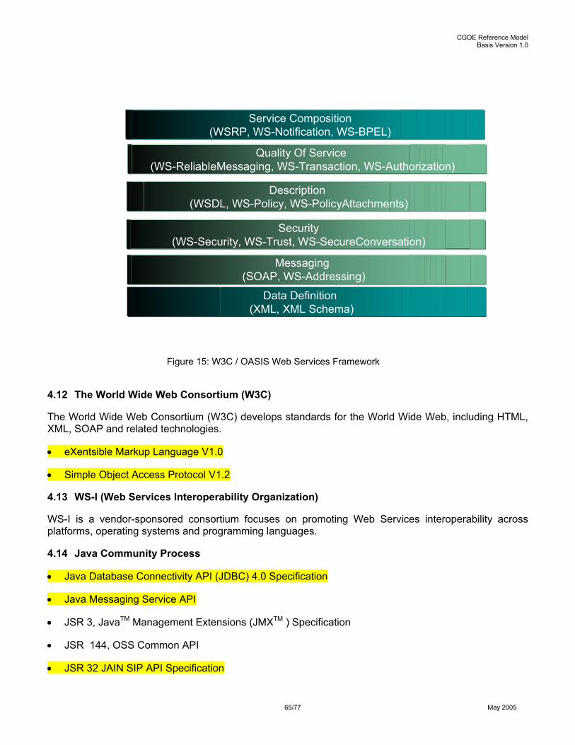
CGOE Reference Model Basis Version 1.0
65/77 May 2005
Figure 15: W3C / OASIS Web Services Framework
4.12 The World Wide Web Consortium (W3C)
The World Wide Web Consortium (W3C) develops standards for the World Wide Web, including HTML, XML, SOAP and related technologies.
• eXentsible Markup Language V1.0
• Simple Object Access Protocol V1.2
4.13 WS-I (Web Services Interoperability Organization)
WS-I is a vendor-sponsored consortium focuses on promoting Web Services interoperability across platforms, operating systems and programming languages.
4.14 Java Community Process
• Java Database Connectivity API (JDBC) 4.0 Specification
• Java Messaging Service API
• JSR 3, JavaTM Management Extensions (JMXTM ) Specification
• JSR 144, OSS Common API
• JSR 32 JAIN SIP API Specification
Application ProtocolMessaging
(SOAP, WS-Addressing)
Data Definition (XML, XML Schema)
Description (WSDL, WS-Policy, WS-PolicyAttachments)
Quality Of Service (WS-ReliableMessaging, WS-Transaction, WS-Authorization)
Service Composition(WSRP, WS-Notification, WS-BPEL)
Security(WS-Security, WS-Trust, WS-SecureConversation)

CGOE Reference Model Basis Version 1.0
66/77 May 2005
• JSR 116 SIP Servlet API
4.15 Institute of Electrical and Electronics Engineers
• Portable Operating System Interface (POSIX IEEE 1003.1)
In addition to the Ethernet and IP specifications (see Figure 10), the POSIX Standard is also recommended as a basic requirement to the CGOE compliant operating system.
4.16 Open Source Development Lab
• Carrier Grade Linux Specifications v2.0
4.17 Free Standards Group
• Linux Standards Base Specification 1.3
4.18 PCI Industrial Computer Manufacturer Group
• Intelligent Platform Management Interface V2
4.19 Storage Networking Industry Association
• Storage Management Initiative Specification (SMI-S)

CGOE Reference Model Basis Version 1.0
67/77 May 2005
5 REFERENCE TO GAPS IN OPEN STANDARDS
The following gives a first set of topics for which it may be considered to take on the task to formulate
o a standardized interface or
o a standardized method.
This is a first version and it is subject to changes while the level of detail and the size of the CGOE framework increases.
5.1 Topics of Emerging Standards
This list references topics where interfaces for which the task of formulating a standard has been taken on, but is not finished, yet.
o NASREG and Mobil Ipv4 (DIAMETER)
o End-to-End security (DIAMETER)
5.2 Topics of Possible Helpful Standards
This list contains topics for which a standard would be very desirable, but no identifiable work has begun.
o Protocol neutral data modeling
o Interface of a Load Balancer to a Policy manager (Overload Control)
5.3 Topics of “Vague” Standards
This list references topics where an interface was identified due to the chosen way of defining the function of a component and the boundaries between components. These interfaces might disappear, if in a later stage, unless this is an interface to more than one component or to the application layer.
o Interface to Alarm Management for any other component
o Interface to Log Management for any other component
o Interface to Policy Management for any other component

CGOE Reference Model Basis Version 1.0
68/77 May 2005
6 CONFORMANCE TO REFERENCE MODEL
6.1 Objective
A key objective of OCAF is to define open standards based components that can be used to create network elements, platforms and applications based on common requirements defined in the Carrier Grade Open Environment Reference Model. To this end, a conformance process is defined to ensure that solution providers can specify and acquire components that are “CGOE Conformant” with predictable results. For the technology provider the conformance process provides the ability to declare that a product conforms to one or more CGOE defined components.
The Conformance Capability ties into steps 5 and 6 of the Six Step Process defined in Section 1 of this document. The Conformance Capability facilitates the assembling of components (step 5) by ensuring that CGOE conformant components acquired by a Solution Provider interoperate. In the same manner, Conformance also facilitates the composition (step 6) of service building blocks by the Service Provider.
This section establishes the intent and direction for a Conformance Capability. Future versions will detail the source of requirements and method for declaring Conformance to the component definitions in the CGOE Reference Model.
6.2 Context
Section 3 provides a high level description of applicable components. In addition to describing more components, future versions of the CGOE Reference Model will describe the detailed functional and non-functional properties, interfaces, and standards that will be the basis for conformance.
Figure 16: Context for Compliance
B1 B2 B3 Bn
C1
C2
C3
Cn
C4
FR1-nNR1-nSR1-n
• Service (S1)• Service Building Block (B1-n )• COTS Component Category (CC1-n )• COTS Component (C1-n )• Functional Requirement (FR1-n )• Non Functional Requirement (NR1-n )• Standard Requirement (SR1-n )
CC1
S1
CC2
CC3
CC4
CCn
FR1-nNR1-nSR1-n
FR1-nNR1-nSR1-n
FR1-nNR1-nSR1-n
FR1-nNR1-nSR1-n
FR1-nNR1-nSR1-n
FR1-nNR1-nSR1-n
FR1-nNR1-nSR1-n
FR1-nNR1-nSR1-n
FR1-nNR1-nSR1-n
FR1-nNR1-nSR1-n
FR1-nNR1-nSR1-n
FR1-nNR1-nSR1-n
FR1-nNR1-nSR1-n
FR1-nNR1-nSR1-n
FR1-nNR1-nSR1-n
FR1-nNR1-nSR1-n
FR1-nNR1-nSR1-n
FR1-nNR1-nSR1-n
FR1-nNR1-nSR1-n
1) CGOE Reference Model Component descriptions
2) Service Building Block component column
3) Building block component requirements

CGOE Reference Model Basis Version 1.0
69/77 May 2005
As outlined in Section 1, the mapping matrices define the COTS components necessary to implement a specific NGN service’s (like IPCentrix) Building Block (like HSS, CSCF, GLMS, etc.) considered for conformance. The COTS components are listed in columns of “green boxes” with the functional and non-functional interfaces, and standards requirements detail for each component of the specific Building Block listed in the “yellow boxes”.

CGOE Reference Model Basis Version 1.0
70/77 May 2005
APPENDIX A – LIST OF ACRONYMS
Abbreviation Expansion 3GPP 3rd Generation Partnership Projects 3GPP2 3rd Generation Partnership Project 2 AAA Authentication, Authorization, Accounting ASM Assembly Language BGP Border Gateway Protocol BHCA Busy Hour Call Attemp CGL Carrier Grade Linux COPS Common Open Policy Service COTS Commercial off -the shelf CORBA Common Object Request Broker Architecture CPE Customer Premise Equipment DNS Domain Name Service EJB Enterprise Java Beans FCAPS Faults, Configuration, Accounting, Performance, Security GSM Global System for Mobile Communication HA High Availability HTTP Hyper Text Transfer Protocol IETF Internet Engineering Task Force IP Internet Protocol ISV Independent Software Vendor J2EE Java 2 Enterprise Edition JAIN Java API for Integrated Networks JINI Java Intelligent Networking Interface JNI Java Native Interface LDAP Lightweight Directory Access Protocol LSB Linux Standards Base MGCP Media Gateway Controller Protocol MMS Multimedia Messaging Service NAT Network Address Translation NEBS Network Equipment Building System NEP Network Equipment Provider OMA Open Mobile Alliance OSA Open Service Access OSDL Open Source Development Lab PSTN Public Switched Telephone Network RADIUS Remote Authentication Dial In User Service Protocol RFC Request For Comments RTP Real Time Protocol SAF Service Availability Forum SCCP Signaling Connection Control Part SCS Service Capability Server SCTP Stream Control Transmission Protocol SIGTRAN Signaling Transport SIP Session Initiation Protocol SLA Service Level Agreement SOAP Simple Object Access Protocol

CGOE Reference Model Basis Version 1.0
71/77 May 2005
Abbreviation Expansion TDM Time Division Multiplexing TMF Telecommunications Management Forum TLS Transport Layer Security UML Unified Modeling Language WAP Wireless Access Protocol XA eXtended Architecture

CGOE Reference Model Basis Version 1.0
72/77 May 2005
APPENDIX B – GLOSSARY OF TERMS
Term Explanation within OCAF context All-IP All-IP networks provide all the essential services (real-time voice/video and
non real-time data) in one packet-based network without using circuit switched network (for voice). The IP network is implemented end-to-end i.e. from the terminal to the server. The benefit is to have all services over the one uniform packet access and backbone network.
Application An application is a piece of software answering a set of user's requirements using telecommunication network services via an IT system, i.e. an application is a set of activities performed to respond to the needs of the users in a given situation for purposes such as business, education, personal communication or entertainment. It implies software and hardware utilization could be performed in a fully or partially automatic way and could be accessed locally or remotely. In the last case, it requests use of telecommunication services. Consequently, an application is the implementation of a bundle of user interfaces, well defined interfaces and requirements to its runtime environment, stand alone installable, pluggable and configurable SW, integrated management support (FCAPS), well defined SW architecture. Example for application: - IP Centrex
Application architecture A specific architecture of a use case scenario is chosen within the Solution Working Group process to formulate the building blocks of the use case.The decision for certain architecture is guided by pragmatic working-level objectives, not with the intention in mind to favor one or the other approach.
Application enabling middleware
Application Enabling Middleware is the specific programming placed between the application logic layer and its base operating platform, providing common extensions to general platform functions to meet specific application needs.
Application platform An application platform is used to build and deploy applications, is defined by its APIs and supported protocols. Frameworks are used to supply access to the operating system (OS) and OS related infrastructure services. Frameworks support the abstraction of the OS and Infrastructure Services (Key for HW abstraction and OS abstraction, examples .NET, J2EE, Web-Services). Each application platform supplies a unique set infrastructure services.
Application programming interface (API)
A programming mechanism that allows a component or system function to expose its capabilities to other components. An API supports component-to-component communication.
Base operating platform A base operating platform spans multiple system layers and component (functional) categories comprised of many different technologies. These are used across multiple different building blocks. Examples: - Database System - Operating System - Programming Language
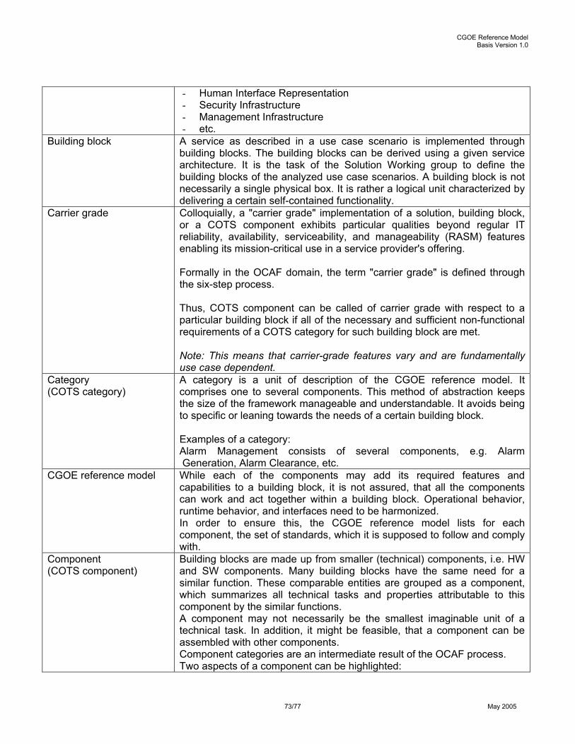
CGOE Reference Model Basis Version 1.0
73/77 May 2005
- Human Interface Representation - Security Infrastructure - Management Infrastructure - etc.
Building block A service as described in a use case scenario is implemented through building blocks. The building blocks can be derived using a given service architecture. It is the task of the Solution Working group to define the building blocks of the analyzed use case scenarios. A building block is not necessarily a single physical box. It is rather a logical unit characterized by delivering a certain self-contained functionality.
Carrier grade Colloquially, a "carrier grade" implementation of a solution, building block, or a COTS component exhibits particular qualities beyond regular IT reliability, availability, serviceability, and manageability (RASM) features enabling its mission-critical use in a service provider's offering. Formally in the OCAF domain, the term "carrier grade" is defined through the six-step process. Thus, COTS component can be called of carrier grade with respect to a particular building block if all of the necessary and sufficient non-functional requirements of a COTS category for such building block are met. Note: This means that carrier-grade features vary and are fundamentally use case dependent.
Category (COTS category)
A category is a unit of description of the CGOE reference model. It comprises one to several components. This method of abstraction keeps the size of the framework manageable and understandable. It avoids being to specific or leaning towards the needs of a certain building block. Examples of a category: Alarm Management consists of several components, e.g. Alarm Generation, Alarm Clearance, etc.
CGOE reference model While each of the components may add its required features and capabilities to a building block, it is not assured, that all the components can work and act together within a building block. Operational behavior, runtime behavior, and interfaces need to be harmonized. In order to ensure this, the CGOE reference model lists for each component, the set of standards, which it is supposed to follow and comply with.
Component (COTS component)
Building blocks are made up from smaller (technical) components, i.e. HW and SW components. Many building blocks have the same need for a similar function. These comparable entities are grouped as a component, which summarizes all technical tasks and properties attributable to this component by the similar functions. A component may not necessarily be the smallest imaginable unit of a technical task. In addition, it might be feasible, that a component can be assembled with other components. Component categories are an intermediate result of the OCAF process. Two aspects of a component can be highlighted:

CGOE Reference Model Basis Version 1.0
74/77 May 2005
- a set of specific technical tasks - a (sometimes optional) set of properties. Examples of components: - database system - operating system - management middleware - etc.
Component instance = « instance »
A component instance is a specific representation of a component, which satisfies the specific needs of building a given building block. Technology providers develop component instances.During the engineering process within the solution providers, instances are chosen according to the requirements and integrated to eventually stage the entire building block Examples of component instances: -Linux - management middleware for Q3-access
Control plane The Control Plane performs the call control and connection control functions. Through signaling, the control plane sets up and releases connections, and may restore a connection in case of a failure (see ITU G.8080/ Y.1304 (01), 3.10).
DIAMETER Next generation RADIUS IETF standards effort
Extended operating platform
An extended operating platform adds more system layers and component (functional) categories to the base operation platform to host specific application systems. Examples: - Web Server - Application Server - Database Server - Directory Server - Transaction Handling - Business Engines
Framework A framework is an environment that provides a partial solution, usually automating a particularly tedious or difficult part of an application project. There are development frameworks and runtime frameworks. A development framework provides pre built code and application skeletons that developers can use to implement solutions quickly and consistently. A runtime framework often implements middleware functionality (see Anne Thomas Manes: Web Services).
Functional requirements The functionality of a building block can be described as a set of interfaces, capabilities, and features, which it adds to service architecture.
Lif cycle management The management of a component, including loading it into memory, allocating the system resources it needs, and removing it when it is complete. The lifecycle management of a component comprises also the Software Management Functions, i.e. first installation of the component,

CGOE Reference Model Basis Version 1.0
75/77 May 2005
the management of upgrades and updates of new releases / versions of the component.
Management plane The Management Plane performs management functions for the Transport Plane, the control plane and the system as a whole. It also provides coordination between all the planes. The following management functional areas identified in ITU-T Rec. M.3010 are performed in the management plane: - performance management; - fault management; - configuration management; - accounting management; - security management The TMN architecture is described in ITU-T Rec. M.3010, additional details of the management plane are provided by the M-series Recommendations (see ITU G.8080/Y.1304 (01), 3.14).
Middleware A software package that sits between the application code and its underlying platform, providing easy access to core system facilities such as the network, storage and processors (see Anne Thomas Manes: Web Services).
Non-functional requirements
This is a list of features that a building block must provide in order to ensure a certain behavior within the service architecture. This list mostly represents requirements to allow for smooth operations and life cycle management.
Network Equipment Building System (NEBS)
This is a list of features that provide certain physical characteristics for systems located within the provider premises that support core network infrastructure.
• GR-63 CORE Physical Protection Standards
o Temperature/Humidity/Altitude
o Transportation/Handling
o Seismic/Vibration
o Fire Spread/Needle Flame Analysis
o Airborne Contaminants
o Illumination/Acoustic Noise
• GR-1089 CORE EMC/Electrical Safety
o 1st and 2nd Level Lightning and AC Power Fault
o Radiated and Conducted Emissions/Immunity
o ESD
o Electrical Safety/Bonding and Grounding
o DC Potential
o Short Circuit

CGOE Reference Model Basis Version 1.0
76/77 May 2005
“Open” A component can be called open when it is capable of being accepted, rejected, extended and replaced in a building block with minimal restriction and regulation, following commonly accepted, publicly available criteria. This means the extent in which components are determined to be open is use case depended.
Operating platform = platform = runtime environment
An operating platform is (see Anne Thomas Manes: Web Services) an amalgam of many different infrastructure technologies that host application systems. Examples of key components of an operating platform: -Operating System -Programming language -Human Interface Representation -Database Server -Security Infrastructure -Management Infrastructure - etc.
Property With respect to a given use case scenario, a property is non-functional aspect of an instance. Nevertheless, the properties describe the expected behavior of an instance, that help either the service provider, the service administrator, the solution provider, or the technology provider in dealing with the instance. Examples of properties: -Capable of rollback, -Stateless, -Clustering-ready via SAF-framework, -Load monitoring and overload detection, - memory footprint less than x Mbytes, etc.
Reference architecture Reference architecture is a description of the design of a system. Reference architecture identifies the functional components of a system. It also defines the relationship among those components and establishes a set of constraints upon each (see Anne Thomas Manes: Web Services).
Service plane The service plane comprises: a) service presentation functionality being presented to the end user; b) service implementation aspects with which the end user interacts. For example, service invocation, control service level agreement function, etc. Note that a) and b) use the totality of the transfer capabilities including control and management functionalities (see ITU Y.1241 (01), 3.1; Y.1401 (00), 3.1). Note: Example is enhanced services such as SMS, WAP, etc. Usually application servers are deployed in the services plane.
Service provider A company that offers end-to-end telecommunication services (fixed/mobile, voice/data) to customers. Those services or individual aspects of them (from a user’s or a provider’s point of view) can be described in use case scenarios.

CGOE Reference Model Basis Version 1.0
77/77 May 2005
Examples of service providers within OCAF membership: Comcast, Deutsche Telecom, France Telecom, NTT, Telecom Italia, etc.
Solution provider Company, engineering and producing building blocks and solutions and selling them to service providers. Examples of solution providers within OCAF membership: Alcatel, Lucent, Nortel, Siemens, etc.
Technical task With respect to a given use case scenario, the technical task is the functional work performed by a component, which justifies the need for a given component. Examples of technical task: - XML parsing, - RTP forwarding, - execution of SIP servlets, etc.
Technology provider Company, developing instances, which solution providers integrate into building blocks. Examples of technology providers within OCAF membership: HP, IBM, Sun, Motorota, etc.
Transport plane The Transport Plane provides bi-directional or unidirectional transfer of user information, from one location to another. It can also provide transfer of some control and network management information. The Transport Plane is layered; it is equivalent to the Transport Network defined in ITU-T Rec. G.805 (see ITU G.8080/ Y.1304 (01), 3.25). Note: The Transport Plane carries the actual payload (e.g. between terminals, systems or phones devices). Typically reflects the Network Layer, Link Layer, and Physical Layer of the OSI Reference Model.
Use case scenario High-level description of a telecommunication service (or a specific aspect of it) from a customer’s (i.e. the user) and a service provider’s point of view. Appropriate measures to describe the use-case depend on its specifics (e.g. UML, call-flow graphs, etc). Examples from OCAF process: - Push-over-Cellular (PoC) - IP Centrex (IPC) - etc.