cas3 interface english user manual
DESCRIPTION
User manual of the CAS 3 programming interfaceTRANSCRIPT

7/21/2019 Cas3 Interface English user manual
http://slidepdf.com/reader/full/cas3-interface-english-user-manual 1/53
Cas Interface 3
User’s Manual
English
- May 2005 -

7/21/2019 Cas3 Interface English user manual
http://slidepdf.com/reader/full/cas3-interface-english-user-manual 2/53
Cas Interface 3 – User’s Manualwww.duolabs.com – All rights reserved.
2
© 2003-2005 Duolabs srl
Duolabs, Cas Interface 3 and Cas Interface Studio are trademarks of Duolabssrl registered in Italy and in other countries.
The names of other products quoted in this document may be trademarks oftheir respective owners.
Duolabs srl assumes no liability resulting from errors or technical omissionscontained in this manual or from accidental or indirect damages related to thesupply, performance or use of this material. All the information of this manualis supplied as is, without additional warranties including, without anywhatsoever limitation, implicit warranties of merchantability or suitability. Allthe information contained in this manual may be subject to changes withoutnotice. No part of this manual can be interpreted as additional warranty.
No part of this publication may be reproduced without the written authorizationof Duolabs Srl.
7/21/2019 Cas3 Interface English user manual
http://slidepdf.com/reader/full/cas3-interface-english-user-manual 3/53
Cas Interface 3 – User’s Manualwww.duolabs.com – All rights reserved.
3
Contents
1. Premise
2. Kit
3.
Connectors
4. First steps
5. Cas Studio
• Sm a r t Ca r d
• Cam M o d u l e• Re p a i r
• Re c e i v e r
• U t i l i t i e s
6. Technical data
Appendix A – Opening a Cam
Appendix B – Closing a Cam
General information

7/21/2019 Cas3 Interface English user manual
http://slidepdf.com/reader/full/cas3-interface-english-user-manual 4/53
Cas Interface 3 – User’s Manualwww.duolabs.com – All rights reserved.
4
1. Premise
Cas Interface 3, the evolution of Cas Interface 2, combines in a single productall the features of Cas Interface 2, its Add-on and many additional options.This new release offers very advanced technical features. As compared to CasInterface 2, it enables to fully manage PCMCIA connectors and easily connectexternal additional modules.However, the most interesting novelty derives from the possibility of beingable to emulate the PCMCIA port of a Common Interface (EN50221) receiverand thus use the Cam directly as if it were inserted in a receiver.Consequently, Cas Interface 3 can also be used by professionals to test a CAM
(Conditional Access Module) without inserting it in a receiver.Cas Interface 3 also enables users to manage and program several types ofSmartCards, which includes both current ones and those yet to be developed.Cas Interface 3 can therefore be regarded a multifunction programmer suitablefor the management of J-Tag, ISP, I2C, etc., through a USB port.
Cas Interface 3 supports the programming and reparation of the followingmodules:
• Magic Cam, Matrix Cam, Matrix Revolution, Matrix Reloaded, Matrix Reborn,
and all CAMs based on SIDSA chipsets, which can be managed directly bymeans of a PCMCIA connector. For a full list of supported modules, open theGraphics Menu of Cas Studio. Remember to download the latest release fromwww.duolabs.com.
• Joker Cam, Zeta Cam and substantially all CAM modules based on NEOTIONchipsets. These modules can be programmed and repaired using a J-Card.For a full list of supported modules, open the Graphics Menu of Cas Studio.Remember to download the latest release from www.duolabs.com.
• Dragon Cam; it is possible to program any version by inserting the DragonCam into Cas Interface 3 and using a Dummy Card. This mode eliminates
the need of inserting the Dragon Cam into a receiver, which can sometimesdamage the CAMs besides being unpractical. It is also possible to repairfaulty Dragon Cams if they fail to initialize due to a faulty Flash Memory. Todo so, it is sufficient to open the module and connect a few wires, followinga procedure that can be easily implemented even by less expert users.
• X-Cam, with ANGEL and ORION chipsets, standard and premium version. Itis possible to program any version by inserting the X-Cam into Cas Interface3 and using a Dummy Card. This mode eliminates the need of inserting theX-Cam into the receiver, which can sometimes damage the CAMs besidesbeing unpractical. It is also possible to repair faulty X-Cams if they fail toinitialize due to a faulty Flash Memory. In this case it is necessary to openthe module and connect a few wires, following a procedure that can be

7/21/2019 Cas3 Interface English user manual
http://slidepdf.com/reader/full/cas3-interface-english-user-manual 5/53
Cas Interface 3 – User’s Manualwww.duolabs.com – All rights reserved.
5
easily implemented even by less expert users.
The receivers damaged by a faulty Flash Memory that can be repaired are thefollowing:
• DreamBox DM7000 and 5600, 5620• Mahattan, Xtreme, Nextwave 2500 with embedded SIDSA module.
For further information on the programming of Cam modules and receivers,refer to the following chapters.
The Cas Interface 3 software, called Cas Studio, offers a wide range of utilitiesfor PCs in addition to the options for Cams and SmartCards described above.Sim Editor simplifies the management of the phonebook, SMS messages,system files of GSM SmartCards.Card Explorer, a flexible software, able to manage all Visual Basic scripts, isthe best solution to explore the content of SmartCards.Wincrypt enables users to protect their sensitive data, files and databases, asit is specifically designed to encrypt data with secure algorithms (3DES) withSmartCards.
Cas Studio is easy to use and user-friendly thanks to its multilanguage GUIthat is continuously updated.
All the options of Cas Interface 3 are described in detail in this user’s manual.

7/21/2019 Cas3 Interface English user manual
http://slidepdf.com/reader/full/cas3-interface-english-user-manual 6/53
Cas Interface 3 – User’s Manualwww.duolabs.com – All rights reserved.
6
2. Kit
The Kit supplied with Cas Interface 3 comprises:
• 1 Cas Interface 3 device• 1 20-pin female cable, length 30 cm• 1 J-Card• 1 Dummy Card• 1 Case for the Cam Module
Fig. 1

7/21/2019 Cas3 Interface English user manual
http://slidepdf.com/reader/full/cas3-interface-english-user-manual 7/53
Cas Interface 3 – User’s Manualwww.duolabs.com – All rights reserved.
7
3. Connectors
Cas Interface 3 uses several external connectors that are described in detail inthe sections that follow:
• USB connector (Fig. 2): enables to power and use the device with anordinary PC.
• RS-232 serial port (Fig. 2): can be used to convert Cas Interface 3 into anISO 7816 programmer with Phoenix and Smartmouse mode, to allow it to beused with third party programs based on these modes.
Fig.2
• PCMCIA connector (Fig. 3 below ): this is where the CAM to program, repairor test must be inserted.
• SmartCard connector (Fig. 3 above): this is where you insert the SmartCardin order to perform the management tasks of Cas Interface 3 (programming,reading, reviewing, etc.).

7/21/2019 Cas3 Interface English user manual
http://slidepdf.com/reader/full/cas3-interface-english-user-manual 8/53
Cas Interface 3 – User’s Manualwww.duolabs.com – All rights reserved.
8
• 20-pin external connector (Fig. 4): this connector can be used to connectCas Interface 3 to the J-Card, Dummy Card or to receivers that can beprogrammed with a flat cable. The connector can also be used to connectadditional devices in future.
Fig.4
The device also has LEDs that provide information on its status:
• Red LED: indicates that Cas Interface 3 is powered• Flashing green LED: indicates that Cas Interface 3 is programming a Cam,
SmartCard, etc.• Yellow LED: indicates that a Cam or SmartCard has been inserted.
Fig. 3

7/21/2019 Cas3 Interface English user manual
http://slidepdf.com/reader/full/cas3-interface-english-user-manual 9/53
Cas Interface 3 – User’s Manualwww.duolabs.com – All rights reserved.
9
4. First steps
Before using Cas Interface 3, download the test software version called CasStudio from the Download section of www.duolabs.com and verify you have a
USB type A-B connection cable, which can be easily purchased from anycomputer retailer. As this cable is generally used to connect several types ofdevices to computers, like printers, scanners, etc., it is also possible to use anexisting cable, if available.
After downloading the setup file of Cas Studio from the Web, carefully followthese instructions. Verify that Cas Interface 3 is not connected to the PC.
• Run the .exe file. The program creates a folder that contains the filesrequired to install Cas Studio and automatically runs the setup program.
• Carefully follow all the instructions of the setup program.• Once the setup is complete, start Cas Studio by clicking the icon on the
desktop or selecting it from the Duolabs folder in Window’s programs.• Select the interface language using the program pane and carefully follow all
the instructions. When prompted, close Cas Studio.• Connect Cas Interface 3 to the Pc using the USB cable. Follow the procedure
applicable to the operating system in use, as described below:
Windows XP: Windows XP displays “Found New Hardware Wizard” window. Select “Install from a list or specific location”, click “Next” ,select “Include this location in the search” , then click “Browse” to openthe “Browse for Folder ” dialog. Search and select thec:\Programs\duolabs\Cas_Studioxxx\drivers folder you havecreated. Attention: this path may be different if you have specified adifferent folder during setup or if Windows is in other language. xxxstands for the release version of Cas Studio. Click OK, select “Next” and wait for the process to complete. Once the setup is completed,
click “End” . Windows 2000: Windows 2000 displays the “Found New Hardware” dialog. Click “Next”, select “Search for a driver suitable for the device”,then click “Next” , select “Specify Location” , click “Next ” and “Browse”to open the “Locate File” folder. Locate and select thec:\Programs\duolabs\Cas_Studioxxx\drivers folder you havecreated. Attention: this path may be different if you have specified adifferent folder during setup or if Windows is in other language. xxxstands for the release version of Cas Studio. Click “Open”, select Ok,click “Next ” and wait for the process to complete. Once the setup iscompleted, click “End” .
Windows 98: Windows 98 displays the “Found New Hardware

7/21/2019 Cas3 Interface English user manual
http://slidepdf.com/reader/full/cas3-interface-english-user-manual 10/53
Cas Interface 3 – User’s Manualwww.duolabs.com – All rights reserved.
10
Wizard”. Click “Next”, select “Search for the best driver for the device
(recommended)”, click “Next” , select “Specify Location”, click “Browse”(or “Cancel ” if the system prompts you to insert a floppy). Theapplication displays the “Browse for folder ” dialog. Locate and selectthe c:\Programs\duolabs\Cas_Studioxxx\drivers you havecreated. Attention: this path may be different if you have specified adifferent folder during setup or if Windows is in other language. xxxstands for the release version of Cas Studio. Click OK, select “Next”.The application displays “Search for device driver file in:” and “CASInterface 3 USB”. Click “Next ”. Once the setup is complete, click “End” .
Windows Me: Windows Me displays the “Found New Hardware
Wizard”. Select “Specify the location of the driver (advanced)”, click “Next” , select “Specify Location” and click “Browse” (or “Cancel ” if theapplication prompts to insert a diskette). The “Browse for Folder ”dialog displays. Locate and select thec:\Programs\duolabs\Cas_Studioxxx\drivers folder you havecreated. Attention: this path may be different if you have specified adifferent folder during setup or if Windows is in other language. xxxstands for the release version of Cas Studio. Click OK and select “Next”. The application displays “Search for device driver file in:” and “CAS Interface 3 USB”. Click “Next ” once more. Once the setup is
complete, click “End” .
To verify if all the tasks have been performed correctly, select ControlPanel and open the Device Manager tab. Make sure that the “Jungo”folder displays “Cas Interface 3” and that that Devices folder displaysWinDriver.
• After you have completed all the steps above, open Cas Studio. You can nowuse Cas Interface 3.

7/21/2019 Cas3 Interface English user manual
http://slidepdf.com/reader/full/cas3-interface-english-user-manual 11/53
Cas Interface 3 – User’s Manualwww.duolabs.com – All rights reserved.
11
5. Cas Studio
Cas Studio is a software specifically developed by Duolabs to enable you to useCas Interface 3, Cas Interface 2 + Add-on and Dynamite.Cas Studio can be used with Windows 98/ME/2000/XP, but not with WindowsNT. This manual describes the procedures that have to be followed for CasInterface 2, Cas Interface 3 and Dynamite.
The software is able to identify the device connected to the USB port and toself-adapt to it by enabling/disabling the appropriate options.
ATTENTION: to allow the device to be correctly identified and be able tocorrectly use the software, always connect the PC to one device at a time only.
The application starts the identification process as soon as you have connectedthe device with the USB cable. If the device is correctly identified, theapplication displays the serial number of the device. If a problem occurs or thedevice cannot be identified, the application displays an error code. For moreinformation on error codes, visit www.duolabs.com.
The upper section of the window displays the menu that enables you to select
the category of options you can enable. These are:
• SmartCard: for Cas Interface 3, Cas Interface 2 + Add-on and Dynamite.It contains the programming options for SmartCards.
• Cam Module: for Cas Interface 3 and Cas Interface 2.It contains the programming options for CAMs.
• Repair: for Cas Interface 3 only.It contains the reparation options for CAMs.
• Receiver: for Cas Interface 3 and Cas Interface 2.It contains the reparation options for receivers.
•
Utilities: for Cas Interface 3, Cas Interface 2 + Add-on and Dynamite.It contains additional applications.

7/21/2019 Cas3 Interface English user manual
http://slidepdf.com/reader/full/cas3-interface-english-user-manual 12/53
Cas Interface 3 – User’s Manualwww.duolabs.com – All rights reserved.
12
SmartCard
The section below lists the SmartCards that are supported by Cas Studio:
PIC-based:Wafercard (16C84, 16F84, 16F84A)Goldcard (16F84/16F84A + 24C16)Silvercard (16F876/16F877 + 24C64)Greencard (16F876/16F877 + 24C128)Greencard2 (16F876/16F877 + 24C256)Bluecard (16F84A + 24C64)
CanaryCard (16F628 + 24C16)EmeraldCard (16F628 + 24C64)Singlepic (16F876, 16F627, 16F628).
AVR-based:Funcard/Funcard2 (AT90S8515 + 24C64)PrussianCard/Funcard3 (AT90S8515 + 24C128)PrussianCard2/Funcard4 (AT90S8515 + 24C256)PrussianCard3/Funcard5 (AT90S8515 + 24C512)PrussianCard4/Funcard6 (AT90S8515 + 24C1024)
PrussianCard5/Funcard7 (AT90S8515 + 2*24C1024)JupiterCard (AT90S2343 + 24C16)JupiterCard2 (AT90S8535 + 24C64)FunCard ATmega161 (ATmega161 + 24C64)FunCard ATmega163 (ATmega163 + 24C256)FunCard Atmega8515/Funkey2 (Atmega 8515 + 24C256)BlackCard (ATmega128 + 24C256)
OS Card:Titanium CardPlatinum CardM2 CardKnot CardKnot Card2Penta VR3 CardDragon CardOpos CardTitan CardTitan2 Card
To display a full and complete list of SmartCards, select the Graphics Menu in
Cas Studio.

7/21/2019 Cas3 Interface English user manual
http://slidepdf.com/reader/full/cas3-interface-english-user-manual 13/53
Cas Interface 3 – User’s Manualwww.duolabs.com – All rights reserved.
13
Before programming the SmartCard, verify that the PIN-to-PIN serial cable is
not connected to the RS-232 serial port of the Pc.
• To program the PIC-based and AVR-based SmartCards listed above, click “Prog”. The following dialog displays:
Fig. 5

7/21/2019 Cas3 Interface English user manual
http://slidepdf.com/reader/full/cas3-interface-english-user-manual 14/53
Cas Interface 3 – User’s Manualwww.duolabs.com – All rights reserved.
14
Follow this procedure:
• Insert the card into the SmartCard connector of the Add-on (if you areusing Cas Interface 2) or of Cas Interface 3 or of Dynamite.
• Click the button with the question mark to allow the SmartCard to beautomatically identified.
• Select the files you wish to use for programming (Duolabs shall not beliable for damages originating from the files used).
• Click “Write”. You can also specify in which part you wish to write, byclicking the side icon.
Fig. 6
• Click “Read” to read the SmartCard.• Click “Erase” to delete the SmartCard.
The programmer is configured to automatically detect the card inserted inthe connector. Select the appropriate options to disable this feature.
T o r e p a i r a D r a g o n Ca r d L o a d e r , i n s e r t t h e Sm a r t Ca r d d i r e c t l y i n t o
t h e s lo t . T h e Sm a r t Ca r d w i l l b e i d e n t i f i e d a s Fu n c a r d o r G o l d Ca r d .
T h e a p p l ic a t i o n d i s p la y s ( a b o v e t h e i co n o f t h e e x i s t i n g Sm a r t C ar d )
“ Re p a i r D r a g o n C a r d L o ad e r ” . Cl ic k t h e b u t t o n a n d w a i t f o r t h e
r e p a r a t i o n t o b e c om p l e t e d .

7/21/2019 Cas3 Interface English user manual
http://slidepdf.com/reader/full/cas3-interface-english-user-manual 15/53
Cas Interface 3 – User’s Manualwww.duolabs.com – All rights reserved.
15
N o t e f o r e x p e r t u s e r s
To edit a file, click the Notepad icon of the desired file.
To program the OS Card (Titanium, Knot Card, Opos Card, etc.) SmartCardslisted above, click the button of the desired card, then perform the followingoperations:
• Insert the Card into the SmartCard connector of the Add-On (if you areusing Cas Interface 2) or of Cas Interface 3 or of Dynamite.
• Click “Cancel” to resume the original status.• Click “ATR” to reset the card and display the ATR number.
•
Select the desired files for the Card (Duolabs shall not be liable fordamages originating from the files used).
• Click “Write” to start programming.
For Titanium SmartCards only • Click “OS 1.06” to switch from 1.03 to 1.06.
• Click “OS 1.03” to restore the SmartCard to OS 1.03.
• Click “Repair” to re-enable the cards that do not generate an ATRnumber after programming (this option enables you to retrieve theATR number on all cards). The result is not however guaranteed.
Customers interested in purchasing the device for this purpose onlyshould not do so because the result of this feature is not 100%guaranteed, although it has yielded good results during the testingphase.
For Dragon Loader Cards only
• Click the Dragon Card button.• Load the file containing the desired firmware (Duolabs shall not be
liable for damages originating from the files used).• Click “Program Dragon Card”.
Note: if the Dragon Card is damaged, you can repair it by selecting the “Prog” and clicking “Repair Dragon Card Loader”.

7/21/2019 Cas3 Interface English user manual
http://slidepdf.com/reader/full/cas3-interface-english-user-manual 16/53
Cas Interface 3 – User’s Manualwww.duolabs.com – All rights reserved.
16
Cam Module
• To program Cam cards based on SIDSA chipsets, like Magic Cam, MatrixRevolution, Matrix Reloaded, Matrix Reborn, etc. (to view a full and
updated list, select the Graphics Menu in Cas Studio ), click the corresponding buttonand perform the following operations:
• Insert the Cam card into the CAS Interface. All the CAM data willbe displayed on screen.
• Select the “General” tab and click “Delete All”.• Click “Open File” and select the correct file (Duolabs shall not be
liable for damages originating from the files used).• Click “Write”. The horizontal bar starts scrolling until the writing
process has completed.• To completely reprogram the CAM, you need to program the
Xilinx chip too. To do so, click “Write Xilinx” and select the filethat corresponds to the Xilinx chip. The programming processstarts (Duolabs shall not be liable for damages originating fromthe files used).
• To verify that the writing task is correctly being performed, click “Verify”.
• To delete the dialog that displays the CAM data, click “DeleteMonitor”.
You can also read part of the CAM Flash by specifying the beginning and theend of the part you wish to read in hexadecimal digits (i.e. 10000 - 20000)in the “Advanced” tab and clicking “Read from CAM”.
• To program CAMs based on NEOTION chipsets, like SkyCrypt, ZetaCAM,@Sky, Joker, Free-X TV, IceCrypt etc. (to view a full and updated list, select the
Graphics Menu in Cas Studio ), click the corresponding button and carefully followthe procedure described below.

7/21/2019 Cas3 Interface English user manual
http://slidepdf.com/reader/full/cas3-interface-english-user-manual 17/53
Cas Interface 3 – User’s Manualwww.duolabs.com – All rights reserved.
17
Fig. 7
• Insert the J-Card as shown in the figure (Attention: it is veryimportant to initially insert the J-Card obliquely, as shown in thesecond pane of Figure 7).
• Insert the Cam into the Cas Interface (it is very important to first
insert the J-Card), then connect the other end of the flat cable tothe external connector of the Cas Interface.
• Click “Connect”. The application displays a square, which is red ifthe J-Card has been inserted improperly or green if it has beeninserted correctly. If the card has been inserted incorrectly, trymoving it delicately to the right until the square becomes green). Ifthe square is green, the application displays "Joker Connected".Press the long button “When the connection is stable, click here”next to the square.
• Click "Open File" and select the correct file (Duolabs shall not be
liable for damages originating from the files used).• Click “Write”. The progress bar starts moving. The process requires
approximately 5 minutes. Click “Verify during programming” towrite and check that the bytes being transferred are correct.
• Remove the Cam, THEN the J-Card.
• To program an X-CAM (connect the Add-on if you are using Cas Interface 2),click the corresponding button, then perform the following operations:
•
Connect one end of the flat cable (the one used for the J-Card) to the

7/21/2019 Cas3 Interface English user manual
http://slidepdf.com/reader/full/cas3-interface-english-user-manual 18/53
Cas Interface 3 – User’s Manualwww.duolabs.com – All rights reserved.
18
Dummy card and the other end to the external connector of Cas
Interface 3 (or of the Add-On if you are using Cas Interface 2).• Insert the Dummy Card into the X-Cam, verifying that the contacts
are in the correct position, as shown in the figure.
Fig. 8
If you are using Cas Interface 2:
Insert the Cam with the Dummy Card into the receiver.
Fig. 9

7/21/2019 Cas3 Interface English user manual
http://slidepdf.com/reader/full/cas3-interface-english-user-manual 19/53
Cas Interface 3 – User’s Manualwww.duolabs.com – All rights reserved.
19
Switch the receiver on and open the Cam Menu to check if the
status of the Cam is “virgin state”.
o Case 1: the Cam Menu displays “XCAM MODULE”, indicatingthat there is no firmware (the status of the CAM is “virginstate”). In this case, perform the following operations:
• Click the button with the three dots to open the dialogthat enables you to select the file with the updates,then select the file (Duolabs shall not be liable fordamages originating from the files used).
•
Click “Start Programming”: the programming starts.The programming process can be interrupted at anytime by click “Stop Programming”.
As soon as the programming is complete, the applicationdisplays “Programming successfully”.To be able to use the CAM after it has been programmed,extract it from the receiver and reinsert it.
o Case 2: the CAM Menu displays XCAM MODULE to indicate
that the firmware is already present. In this case, you alwaysNEED to delete the existing content before programming thenew firmware.To delete the content of the Cam, perform the followingoperations:
Select XCAM xxxxxx (where the x indicate a coderelated to the firmware already present in the CAM),then click OK.
Select “Serial Update” in the following menu, then click “OK”.
Click “Delete XCAM” in the dialog of Cas Studio. Fromnow on, you have 7 seconds to click OK to enable “Activate Loader”. The Cam deletion process will startfrom when you click the button.
After completing the deletion, click OK to confirm theend of the operation, remove the Cam from thereceiver and reinsert it. The application generallydisplays “XCAM MODULE” after a few seconds toindicate that the content of the Cam has been deleted(i.e. the CAM is in “virgin state”).
At this point you can start programming the Cam

7/21/2019 Cas3 Interface English user manual
http://slidepdf.com/reader/full/cas3-interface-english-user-manual 20/53
Cas Interface 3 – User’s Manualwww.duolabs.com – All rights reserved.
20
following the steps illustrated in Case 1.
If you are using Cas Interface 3:
Insert the X-Cam with the Dummy Card into the PCMCIAconnector of Cas Interface 3, as shown in the figure.
Click “...” and select the appropriate file (Duolabs shall not beliable for damages originating from the files used).
Follow the displayed instructions.
• To program a Dragon Cam (which is possible with Cas Interface 3 only),click the corresponding button and perform the following operations:
• Connect one end of the flat cable to the external connector of CasInterface 3 and the other end to the Dummy Card.
• Insert the Dummy Card into the Dragon Cam.
Fig. 10

7/21/2019 Cas3 Interface English user manual
http://slidepdf.com/reader/full/cas3-interface-english-user-manual 21/53
Cas Interface 3 – User’s Manualwww.duolabs.com – All rights reserved.
21
• Insert the Dragon Cam with the Dummy Card into the PCMCIA
connector of Cas Interface 3, as shown in the figure.
• Click “...” and select the appropriate file (Duolabs shall not be liable fordamages originating from the files used).
• Follow the displayed instructions.
Fig. 11

7/21/2019 Cas3 Interface English user manual
http://slidepdf.com/reader/full/cas3-interface-english-user-manual 22/53
Cas Interface 3 – User’s Manualwww.duolabs.com – All rights reserved.
22
Repair
This option enables you to repair Dragon Cams and X-Cams and differs fromthe Cam Module option because it requires you to open the metal case of theCam in order to weld the necessary wires.
To repair a Dragon Cam or X-Cam (which is possible with Cas Interface 3only), follow this procedure:
• Connect one end of the flat cable to the external connector of Cas Interface3 and the other end to the Dummy Card.
• Open the Cam and extract the circuit board (see Appendix A).
• Weld some wires (up to a maximum length of 10 cm) from the Dummy Cardto the Cam, as shown in the figures (that show some examples of severaltypes of Dragon Cams and X-Cams; refer to the image related to the type ofCam you are using).To determine the type of Dragon Cam used, read the label on the rear.
• Close the Cam. This procedure is easier if you have a spare case for the
open Cam (see Appendix B).
The pages that follow show the wiring diagrams related to the connection ofseveral types of Dummy Cards to Cams.
It is advisable to perform the connections in the exact order specified.

7/21/2019 Cas3 Interface English user manual
http://slidepdf.com/reader/full/cas3-interface-english-user-manual 23/53
Cas Interface 3 – User’s Manualwww.duolabs.com – All rights reserved.
23
W i r in g d i a g r a m f o r t h e c o n n e ct i o n o f a D r a g o n Cam 2 . 5 - 2 .6 w i t hD u m m y Ca r d .
Fig. 12

7/21/2019 Cas3 Interface English user manual
http://slidepdf.com/reader/full/cas3-interface-english-user-manual 24/53
Cas Interface 3 – User’s Manualwww.duolabs.com – All rights reserved.
24
W i r in g d i a g r a m t o co n n e c t a D r a g o n Cam 3 . x - 4 .x w i t h D um m y Ca r d .
Fig. 13

7/21/2019 Cas3 Interface English user manual
http://slidepdf.com/reader/full/cas3-interface-english-user-manual 25/53
Cas Interface 3 – User’s Manualwww.duolabs.com – All rights reserved.
25
W i r in g d i a g r a m f o r t h e c o n n e ct i o n o f a X- Cam Ch i p O r io n w i t h D um m y
Ca rd .
Fig.14

7/21/2019 Cas3 Interface English user manual
http://slidepdf.com/reader/full/cas3-interface-english-user-manual 26/53
Cas Interface 3 – User’s Manualwww.duolabs.com – All rights reserved.
26
W i r in g d i a g r a m f o r t h e c on n e c t i o n o f a X -Cam Ch i p A n g e l w i t h D um m y
Ca rd .
Fig. 15

7/21/2019 Cas3 Interface English user manual
http://slidepdf.com/reader/full/cas3-interface-english-user-manual 27/53
Cas Interface 3 – User’s Manualwww.duolabs.com – All rights reserved.
27
• After welding the wires on the Cam and Dummy Card, insert the Cam intothe PCMCIA connector of Cas Interface 3.
Fig. 16
• Attention: inserting a Cam without metal case into the PCMCIAconnector is very delicate operation that could potentially damagethe two electronic devices. Always insert the CAM into the PCMCIAconnector very carefully, making sure that the Cam is pointingupwards (i.e. that its chips are pointing upwards) and that it isperfectly centered, both horizontally and vertically, as compared tothe connector of Cas Interface 3 (Fig. 17).

7/21/2019 Cas3 Interface English user manual
http://slidepdf.com/reader/full/cas3-interface-english-user-manual 28/53
Cas Interface 3 – User’s Manualwww.duolabs.com – All rights reserved.
28
Fig. 17
• Click the button of the Dragon Cam or X-Cam.
• Select the exact type of Cam you wish to repair from the menu.
• Click “Repair”. The reparation process requires several minutes.

7/21/2019 Cas3 Interface English user manual
http://slidepdf.com/reader/full/cas3-interface-english-user-manual 29/53
Cas Interface 3 – User’s Manualwww.duolabs.com – All rights reserved.
29
Receiver
• To program an Xtreme receiver, click the corresponding button andperform the following operations:
• If you are using Cas Interface 2 with Add-on, connect the flat cable tothe Add-on and to Xtreme, as shown in the figure (Fig. 18):
• If you are using Cas Interface 3, insert one end of the flat cable into theexternal connector and the other end into Xtreme, as shown in the figure(Fig. 19):
Fig. 18

7/21/2019 Cas3 Interface English user manual
http://slidepdf.com/reader/full/cas3-interface-english-user-manual 30/53
Cas Interface 3 – User’s Manualwww.duolabs.com – All rights reserved.
30
Fig. 19
•
Click “Connect”. All the Cam data display.• Click “Delete All”.
• Click “Open File” and select the desired file (Duolabs shall not be liablefor damages originating from the files used).
• Click “Write”; the progress bar displays until the process completes.• To be able to completely reprogram the receiver, you need to program
also the Xilinx chip. To do so, click “Write Xilinx” and select the file thatcorresponds to the Xilinx chip to start the programming cycle (Duolabsshall not be liable for damages originating from the files used).
• To program a NextWave receiver, click the corresponding button andperform the following operations:
• Open the NextWave receiver and remove its internal Cam.• If you are using Cas Interface 2, build a cable that enables you to
connect the external connector of Cas Interface 2 to the internal Cam ofthe receiver, as shown in Figure 20:

7/21/2019 Cas3 Interface English user manual
http://slidepdf.com/reader/full/cas3-interface-english-user-manual 31/53
Cas Interface 3 – User’s Manualwww.duolabs.com – All rights reserved.
31
Fig. 20

7/21/2019 Cas3 Interface English user manual
http://slidepdf.com/reader/full/cas3-interface-english-user-manual 32/53
Cas Interface 3 – User’s Manualwww.duolabs.com – All rights reserved.
32
• If you are using Cas Interface 3, build a cable that enables you to
connect the external connector of Cas Interface 3 to the internal Cam ofthe receiver, as shown in Figure 21:
Fig. 21

7/21/2019 Cas3 Interface English user manual
http://slidepdf.com/reader/full/cas3-interface-english-user-manual 33/53
Cas Interface 3 – User’s Manualwww.duolabs.com – All rights reserved.
33
• Click “Connect”. All the Cam data are displayed.
• Click “Delete All”.• Click “Open File” and select the desired file (Duolabs shall not be liable
for damages originating from the files used).
• Click “Write”; the progress bar displays until the process completes.• To be able to completely reprogram the receiver, you need to program
also the Xilinx chip. To do so, click “Write Xilinx” and select the file thatcorresponds to the Xilinx chip to start the programming cycle (Duolabsshall not be liable for damages originating from the files used).
• Retrieve Dreambox Boot.
This option enables to you to retrieve the Dreambox boot. To determine ifthe Boot is really damaged, check the display of the Dreambox. If no data isdisplayed, the boot can be retrieved. All other errors are not supported.Click the button that corresponds to the DreamBox and perform thefollowing operations:
• If you are using Cas Interface 2 with the Add-on, connect the flatcable to the Add-O and to the DreamBox as shown in the figure:
• If you are using Cas Interface 3, insert one end of the flat cable
into the external connector and the other end into the DreamBox
as shown in the figure (the figures refer to two models of
Fig. 22

7/21/2019 Cas3 Interface English user manual
http://slidepdf.com/reader/full/cas3-interface-english-user-manual 34/53
Cas Interface 3 – User’s Manualwww.duolabs.com – All rights reserved.
34
DreamBox: refer to the photo of the model you are using)
DM5600/5620 (Fig. 22) and DM7000 (Fig. 23):
Fig. 22
Fig. 23
• Click “Connect” when the receiver is on.

7/21/2019 Cas3 Interface English user manual
http://slidepdf.com/reader/full/cas3-interface-english-user-manual 35/53
Cas Interface 3 – User’s Manualwww.duolabs.com – All rights reserved.
35
• If the application is able to correctly detect the device, additional
buttons are displayed (“Open File” and “Write”). • Click “Open File” and select the desired file.
N o t e : the file to use must be a 128k boot file, which can bedownloaded from Web sites dedicated to Dreambox ( Duolabs shallnot be liable for damages originating from the files used ).
• Click “Write”.
• To program a Manhattan receiver, click the corresponding button andperform the following operations:
• If you are using Cas Interface 2, disconnect the Add-on (if in use) andbuild a cable to connect the external connector of Cas Interface 2 to theManhattan receiver, as shown in Figure 24:
• If you are using Cas Interface 3, insert one end of the flat cable into theexternal connector and the other end into the Manhattan receiver, asshown in the figure (Fig.25):
Fig. 24

7/21/2019 Cas3 Interface English user manual
http://slidepdf.com/reader/full/cas3-interface-english-user-manual 36/53
Cas Interface 3 – User’s Manualwww.duolabs.com – All rights reserved.
36
Fig. 25
• Click “Connect”. All the Cam data displays.• Click “Delete All”.• Click “Open File” and select the desired file (Duolabs shall not be liable
for damages originating from the files used).
• Click “Write”; the progress bar displays until the process completes.• To be able to completely reprogram the receiver, you need to program
also the Xilinx chip. To do so, click “Write Xilinx” and select the file thatcorresponds to the Xilinx chip to start the programming cycle (Duolabsshall not be liable for damages originating from the files used).

7/21/2019 Cas3 Interface English user manual
http://slidepdf.com/reader/full/cas3-interface-english-user-manual 37/53
Cas Interface 3 – User’s Manualwww.duolabs.com – All rights reserved.
37
Utilities
• Using the Phoenix / Smartmouse:Use a Pin-to-Pin serial cable to connect the PC to the serial port of the Add-on (if you are using Cas Interface 2) or of Cas Interface 3 or of Dynamite.Click the Phoenix button to open the dialog in which you can select thedesired mode. Click “Hide” to hide the main dialog. The mode selectionoptions can be selected from a practical menu in the tray bar.
Main dialog:
Fig. 26
Tray Bar Menu (Fig. 27):
Fig. 27
Open Tray Bar Menu (Fig. 28):
Fig. 2
Fig. 3

7/21/2019 Cas3 Interface English user manual
http://slidepdf.com/reader/full/cas3-interface-english-user-manual 38/53
Cas Interface 3 – User’s Manualwww.duolabs.com – All rights reserved.
38
Fig. 28
After selecting the mode, run the software on the COM port.
IMPORTANT: use a pin-to-pin serial cable (the pin 1 on one side mustcorrespond to pin 1 on the other side and so on; this cable must bepurchased separately).
• SimEditor is a software module that enables you to easily and quicklymanage the content of Sim cards installed in mobile phones.
• WinCrypt is a powerful software module that enables you to compress and
encrypt sensitive data. The uniqueness of this application lies in the fact thatthe Sim Card of the mobile phone is used as encryption/decryption key forthe data that needs protecting.
• Cam Explorer is a very practical software module that enables users toexplore the content of Cams and interact with them using a PC, as if theywere in a receiver. This eliminates the need of using the remote control ofthe receiver to select a menu or input alphanumerical text, because it issufficient to use a mouse or keyboard.
Some modules are not supported or are partially supported. Customers areadvised to report all modules that do not work with Card Explorer to allow usto improve the features of Cas Studio.
Fig. 4

7/21/2019 Cas3 Interface English user manual
http://slidepdf.com/reader/full/cas3-interface-english-user-manual 39/53
Cas Interface 3 – User’s Manualwww.duolabs.com – All rights reserved.
39
6. Technical data
• Full Speed connection, 12 Mbit, USB 1.1 and 2.0 compatible
• Compatible with all Windows operating systems
• Does not require external feeders
• Upgradable firmware
• Multifunction external port
• RS-232 serial communication port
• Fully managed PCMCIA slot
• Support for wireless devices (* optional devices)
For a correct maintenance of the device, it is very important to insert the Caminto the slot very carefully without forcing any mechanical movement.
The tampering or opening of the device will invalidate the warranty.

7/21/2019 Cas3 Interface English user manual
http://slidepdf.com/reader/full/cas3-interface-english-user-manual 40/53
Cas Interface 3 – User’s Manualwww.duolabs.com – All rights reserved.
40
Appendix A – Opening the Cam
This section briefly explains how to open the Cam case.
1. Place the Cam on a flat surface and position the flat point of a screwdriveron one of the closing segments of the Cam, as shown in Figure 29:
2. Delicately hammer the upper section of the screwdriver handle using thelatter as a chisel, in order to remove and bend the closing segments shownin Figure 30.
3. Tilt the Cam and repeat the operations described in steps 1 and 2 also forthe other closing segment.
Fig. 29
Fig 30

7/21/2019 Cas3 Interface English user manual
http://slidepdf.com/reader/full/cas3-interface-english-user-manual 41/53
Cas Interface 3 – User’s Manualwww.duolabs.com – All rights reserved.
41
4. Separate the metal plates that form the case and carefully remove the Cam
card, as shown in Figure 31:
Fig.31
7/21/2019 Cas3 Interface English user manual
http://slidepdf.com/reader/full/cas3-interface-english-user-manual 42/53
Cas Interface 3 – User’s Manualwww.duolabs.com – All rights reserved.
42
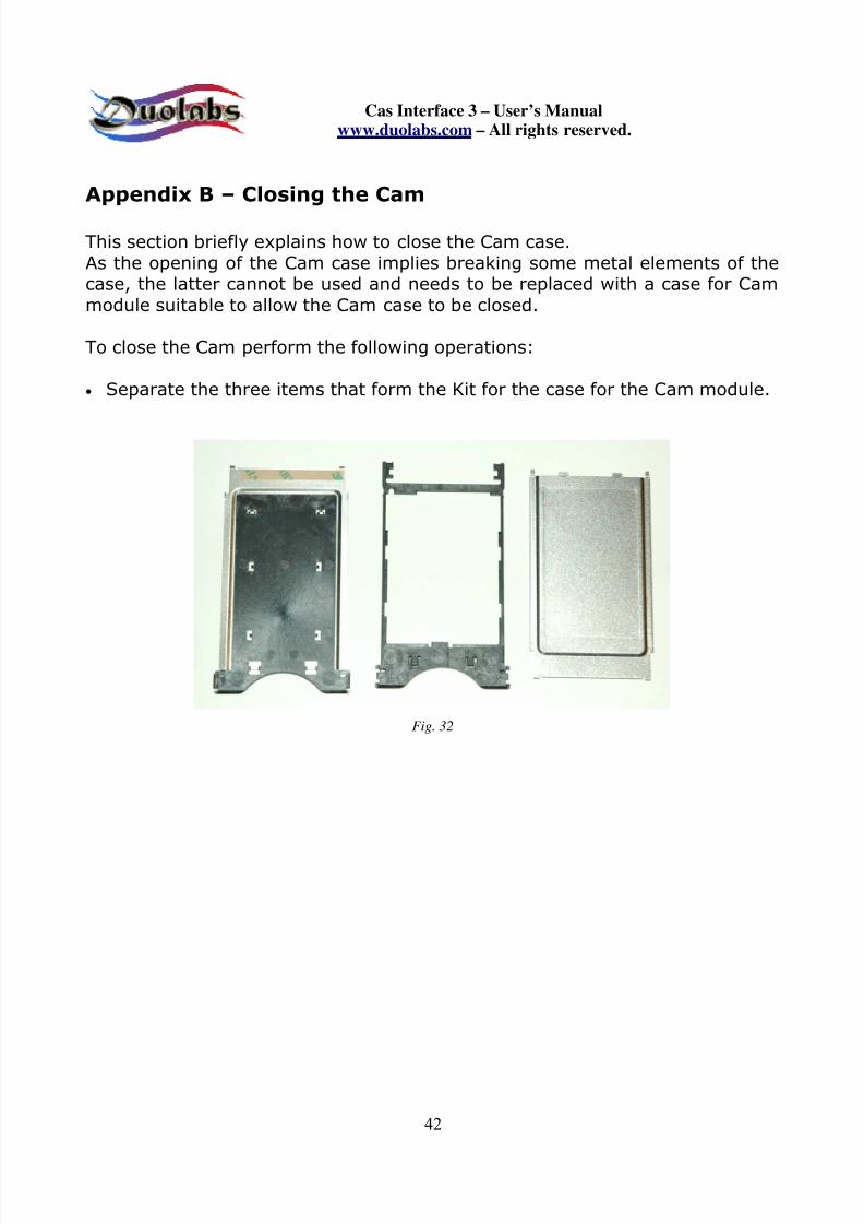
Appendix B – Closing the Cam
This section briefly explains how to close the Cam case.As the opening of the Cam case implies breaking some metal elements of thecase, the latter cannot be used and needs to be replaced with a case for Cammodule suitable to allow the Cam case to be closed.
To close the Cam perform the following operations:
• Separate the three items that form the Kit for the case for the Cam module.
Fig. 32

7/21/2019 Cas3 Interface English user manual
http://slidepdf.com/reader/full/cas3-interface-english-user-manual 43/53
Cas Interface 3 – User’s Manualwww.duolabs.com – All rights reserved.
43
• Insert the Cam card, placing downwards, into the plastic frame of the case.Slide it along the guides, as shown in the following figures (Fig. 33 and 34):
Fig. 33
Fig. 34

7/21/2019 Cas3 Interface English user manual
http://slidepdf.com/reader/full/cas3-interface-english-user-manual 44/53
Cas Interface 3 – User’s Manualwww.duolabs.com – All rights reserved.
44
• Correctly align the Cam and the plastic frame in the two points shown in
Figure 35:
Fig. 35

7/21/2019 Cas3 Interface English user manual
http://slidepdf.com/reader/full/cas3-interface-english-user-manual 45/53
Cas Interface 3 – User’s Manualwww.duolabs.com – All rights reserved.
45
• Remove the liner of the adhesive tape from the metal element with plasticinsert (Fig. 36):
Fig. 36

7/21/2019 Cas3 Interface English user manual
http://slidepdf.com/reader/full/cas3-interface-english-user-manual 46/53
Cas Interface 3 – User’s Manualwww.duolabs.com – All rights reserved.
46
• Place the Cam plate with plastic frame in the point shown above on themetal element (Fig. 37):
Fig. 37
7/21/2019 Cas3 Interface English user manual
http://slidepdf.com/reader/full/cas3-interface-english-user-manual 47/53
Cas Interface 3 – User’s Manualwww.duolabs.com – All rights reserved.
47
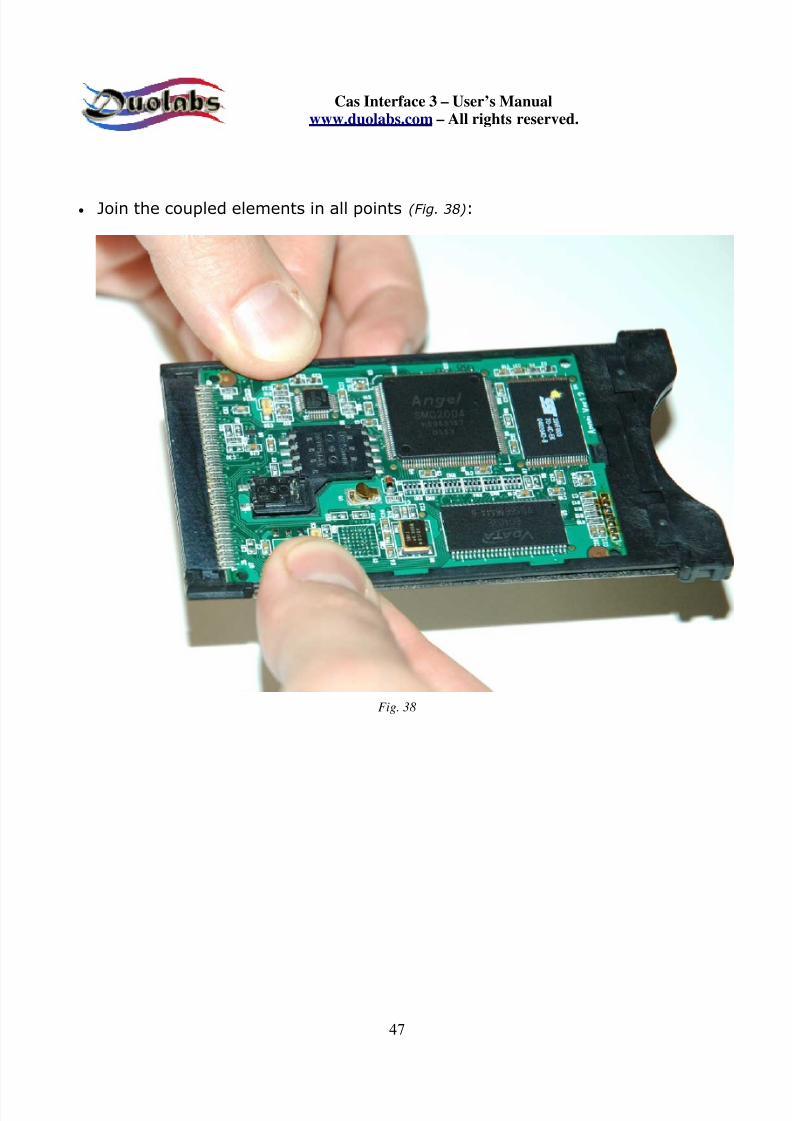
• Join the coupled elements in all points (Fig. 38):
Fig. 38

7/21/2019 Cas3 Interface English user manual
http://slidepdf.com/reader/full/cas3-interface-english-user-manual 48/53
Cas Interface 3 – User’s Manualwww.duolabs.com – All rights reserved.
48
• Remove the liner from the adhesive tape of the other metal element of thecase (Fig. 39):
Fig. 39

7/21/2019 Cas3 Interface English user manual
http://slidepdf.com/reader/full/cas3-interface-english-user-manual 49/53
Cas Interface 3 – User’s Manualwww.duolabs.com – All rights reserved.
49
• Slide the metal element above the Cam plate in order to insert the segmentsinto the plastic slots (Fig. 40):
Fig. 40

7/21/2019 Cas3 Interface English user manual
http://slidepdf.com/reader/full/cas3-interface-english-user-manual 50/53
Cas Interface 3 – User’s Manualwww.duolabs.com – All rights reserved.
50
• Perfectly join the two coupled elements in all points (Fig. 41):
Fig. 41

7/21/2019 Cas3 Interface English user manual
http://slidepdf.com/reader/full/cas3-interface-english-user-manual 51/53
Cas Interface 3 – User’s Manualwww.duolabs.com – All rights reserved.
51
• Check that the metal segments of the PCMCIA connector of the Cam arefirmly joined to the plastic, as shown in Figure 42:
Fig. 42

7/21/2019 Cas3 Interface English user manual
http://slidepdf.com/reader/full/cas3-interface-english-user-manual 52/53
Cas Interface 3 – User’s Manualwww.duolabs.com – All rights reserved.
52
• Check that the side segments are correctly fixed in place (Fig.43):
Fig.43
The final result of the closing operation is shown in Figure 44:
Fig. 44

7/21/2019 Cas3 Interface English user manual
http://slidepdf.com/reader/full/cas3-interface-english-user-manual 53/53
Cas Interface 3 – User’s Manualwww.duolabs.com – All rights reserved.
General information
Duolabs Srl assumes no liability resulting from damages caused by the faultyoperation or improper use of its products. Duolabs Srl shall accept returnedproducts only if these have been used in compliance with the instructionsprovided in this manual or on www.duolabs.com.
Software should be downloaded from www.duolabs.com that is the onlyreputable official Web site.
The manufacturer does not supply .bin or other type of files.
For more detailed information or updates, check the Forum onwww.duolabs.com. The manufacturer reminds all users that the unauthorizeduse of software is punished by law.
No part of this publication may be reproduced without the written authorizationof Duolabs Srl.
Duolabs Srl thanks all users who have supported the research anddevelopment of this product, along with all the beta testers and forums that
have contributed to the circulation of news on it.
The product is identified by a unique serial number. Duolabs reserves the rightto stop the use of its software without notice if it were to be informed onimproper use of the device or of limitations regarding the use of the product.
Duolabs SrlRiccardo Alessi
Duolabs SrlVia Europa 2136050 Cartigliano (Vicenza)
Italy
Tel. +39-0424-828355Fax. +39-0424-598665
Web: www duolabs com