cascade rapide - swift owners club · cascade rapide . installation and user instructions . leave...
TRANSCRIPT
-
.....
CASCADE RAPIDE INSTALLATION AND USER INSTRUCTIONS
Leave these instructions with the appliance
ISTRUZIONI PER UNSTALLAZIONE E L'USO lasciare queste istruzioni con"apparecchio
INSTRUCTIONS DE MONTAGE ET MODE D'EMPLOI Conserver ce mode d'emploi avec rappareil
EINBAU-UND BEDIENUNGSANWEISUNGEN Dieses Heft ist dem I(unden zu uberreichen
INSTRUCCIONES DE ISTALACION Guarde estas instrucciones con e' artefacto
INSTALLATIE-EN GEBRUII(SAANWlJZING DEZE AANWIJZINGEN BU APPARAAT BEWAREN
Bewaar deze instructies bij het apparaat

---------
CASCA.DE 2GE 550mm _._.• 1
CASCADE 2 540mm I ..• I
236
n-= fT I• . • ) ,". oJ ::z _455mm-_
1.
.... [
~Jlr ~t~1[
.,.~""P -:.~
4.
10mml 7._-------CJ
I~ 10.
~~ ~8mm 16,
~----------
19.
~.LJ 2 .
5,
B,
[~~~-=:;~_16,
. ..I c
~---I""W""
A . 11.
14.
c'M ..·l~ GRNI"::-~-r 6'>_ y¢e--L0 R
~I0.4 17.
I
'.\
50mb
20.
o _.--
6,
9.
B 1 9
° 0 °40t--'05 6 ° .J-f-.:-o 7
2JO~03 12,
15,
lB.
21.

ENGLISH
1. SPECIFICATIONS
Water capacity 9 Iitres or 6 litres Water connections Male nozzles to suit 12mm bore reinforced hose. The cold inlet incorporates a non-return valve. Water supply Maximum recommended pressure from pump 1.0 bar Maximum working pressure 2.5 bar
NOT SUITABLE FOR DIRECT CONNECTION TO MAINS WATER SUPPLY
Maximum weight Empty 5.64 kg Full 14.64 kg
Operation Gas Mains Electric
T~mperature range 70'C approx. non-adjustable 70° e approx. non·adjustable
Insulation heat loss 3°e per hour 3° e per hour
Efficiency Better than 75% N/A
Gas connection Female olive compression coupling to suit 8mm or }'4" QJ pipe
N/A
Gas supply pressure Butane 28 mbar Propane 37 mbar Butane/Propane 30 mbar Butane/Propane 50 mbar
N/A
Electrical supply Nominal 1211 DC negative earth only 230v AC 50Hz
Electrical consumption 250 rnA heating 25 rnA standby
3.65A at 230v (830 Wi /2.6A at 230v (61 OW)
Supply Fuses Not supplied 5A
Not supplied 5A
Warm-up time Typically some water at 55°C to 60°C available after 25 mins from switching on
Typically some water available at 55°C to 600 e after 25 mins of switching on
User control Remote controller with indicator lights supplied with heater Not supplied
Safety Features Pressure relief valve set at 2.5 bar and fusible plug set at 96°C both venting onto burner
Must have a double pole illuminated switch outlet with a contact gap of at
Other features least 3mm in each pole
The electronic burner control features protection against flame failure, gas supply interruption and low voltage
As gas only. plus over temperature thermostat with manual reset at 85°C
INSTALLATION INSTRUCTIONS 2. WARNINGS AND INFORMATION
The heater must be installed in accordance with the regulations in force and with these Fitting Instructions. In addition, the installation of the mains electric for the Cascade Rapide GE must be carried out by a competent electrician working to regulations in force, and these Fitting Instructions.
For USER SAFETY attention is drawn to Section 4.1, i.e. Balanced Flue Terminal Position
The gas control circuit must only be connected to a 12 volt DC negative earth supply. Before commencing any work on the caravan disconnect the battery and isolate the caravan from the mains supply.
Mains supply for the Cascade GE should be made via the double pole switched outlet with a contact gap of at least3mm in each pole, and should include an earth connection.
Water hoses should be reinforced, opaque FOOD QUALITY
Mains cable must have a minimum cross sectional area of 1.5mm'
This heater does not contain asbestos or asbestos related products.
The Cascade Rapide and Rapide GE are approved to the relevant sections of EN 89 95/54/EC and EN 60335 and are manufactured to ISO 9002.
The heaters are suitable for installation into caravans complying with the regulations in force.
This appliance must not be connected to a mains water supply, unless regulated with a suitable device to supply a pressure of less than 1.4 Bar (20psi).
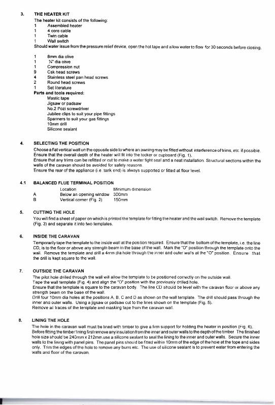
3. THE HEATER KIT The heater kit consists of the following: 1 Assembled heater 1 4 core cable 1 Twin cable 1 Wall switch Should water issue from the pressure relief device, open the hot tape and allow water to flow for 30 seconds before closing.
1 8mm dia olive 1 y.. dia olive 1 Compression nut 9 Csk head screws 4 Stainless steel pan head screws 2 Round head screws 1 Set literature Parts and tools required:
Mastic tape Jigsaw or padsaw No.2 Poz; screwdriver Jubilee clips to suit your pipe fittings Spanners to suit your gas fittings 10mmdrill Silicone sealant
4. SELECTING THE POSITION
Choose a flat vertical wall on the opposite side to where an awning may be filled without interference oltrims, etc. if possible. Ensure that the overall depth of the heater will fit into the locker or cupboard (Fig. 1). Ensure that any trims can be refilled or cut to make a water tight seal and a neat installation. Structural sections within the walls of the caravan should be avoided for safety reasons. Ensure the rear of the appliance (i.e. tank end) is always supported or filled at floor level.
4.1 BALANCED FLUE TERMINAL POSITION Location Minimum dimension
A Below an opening window 300mm B Vertical corner (Fig. 2) 150mm
5. CUTIING THE HOLE You will find a sheet of paper on which is printed the template for filling the heater and the wall switch. Remove the template (Fig. 3) and separate it into two templates.
6. INSIDE THE CARAVAN Temporarily tape the template to the inside wall at the position required. Ensure that the bollom of the template, i.e. the line CD, is to the floor or above any strength beam in the base of the wall. Mark the "0" position through the template onto the wall. Remove the template and drill a 4mm dia hole through the inner and outer walls at the "0" position. Ensure that the drill is kept square to the wall.
7. OUTSIDE THE CARAVAN The pilot hole drilled through the wall will allow the template to be positioned correctly on the outside wall. Tape the wall template (Fig. 4) and align the "0" position with the previously drilled hole. Ensure that the template is square to the caravan body. The line CD should be level with the caravan floor or above any strength beam on the base of the wall. Drill four 10mm dia holes at the positions A, B, C and D as shown on the wall template. The drill should pass through the inner and outer walls. Using a jigsaw or padsaw cut to the lines shown on the template (Fig. 5). Remove all traces of the template and masking tape from the caravan wall.
8. LINING THE HOLE The hole in the caravan wall must be lined with timber to give a firm support for holding Ihe heater in position (Fig. 6). Before filling the timber lining first remove any insulation from the inner and outer walls to the depth olthe timber The finished hole size should be 240mm x 212mm.use a silicone sealant to seal the lining to the inner and outer walls. Secure the inner walls 10 the lining with panel pins. The panel pins shouid be fitted within 1Omm of the edge of the hole at the tope and sides only. Trim the edges of the hole to remove any burrs etc. The use of silicone sealant is to prevent water from entering the walls and floor of the caravan.

9. 230 VOLT CONNECTION (GE ONLY)
Any work on mains electricity should be carried out by a competent electrician working to the regulations in force. Ensure illuminated double pole switched outlet fused at 5 amp should be located in a position convenient for easy operation by the user, i.e. on the outside of the bedding locker adjacent to the appliance. The mains cable should be connected from the fused outlet with a switched contact separation of at least 3mm to either the Residual Current Circuit Breaker or joined into the existing wiring via a 15 amp junction box. The cable required to connect the appliance to the fused mains outlet should be a minimum standard of 3 core double sheathed, with the conductors having a minimum cross sectional area of 1.5mm'. Estimate the length of cable required from the fused outlet to the appliance and allow extra to enable the heater to be partially withdrawn through the side of the caravan without disconnection. Remove the plate covering the electrical connections of the appliance. Prepare the end of the cables as shown in Fig. 7 Pass the prepared end through the cable entry and under the cable clamp. Connect the cable into the three way terminal block (Fig. 8). The Brown wire is connected to the terminal marked 'L', Blue to the 'N' and the GreenlYeliow to the 'E' Tighten the cable clam (A) taking care not to damage the cable or screws. Replace the cover plate with the three screws provided.
10. WATER CONNECTIONS
10.1 Use ONLY reinforced FOOD QUALITY opaque hose or semi-rigid pipe to avoid unpleasant tastes and smells in the water Note: The reason for the use of the opaque hose is that this reduces the possibility of the build up of algae in the system.
10.2 When connecting into the water supply pipes it is advisable to use a 'Y' connector as this does not reduce the flow to the same degree as a TEE' (Fig. 9). Connect the cold feed hose for the heater to the existing cold water supply by the use of a 'Y' connector. Allow enough length on the hose to make the connection to the heater through the hole in the wall of the caravan (Fig. 10). Complete the hot water system allowinglenough hose to make the connection to the heater through the hole in the caravan' wall.
10.3 Pumps and Taps
Taps which controllhe pump by a switch in each tap are considered the most suitable but the heaterwill also work on systems using a pressure switch to control the pump (provided that the pressure operating switch is below 1.4 bar). Where a pressure switch is used, temperature fluctuations can be expected when showering.
11. FiniNG THE HEATER
11.1 Ensure that the 4 core cable is connected to the electronics module at the bottom of the heater. Offer the heater through the hole in the wall, making sure that the multicore cable, and the 230 volt cable in the case of the Rapide GE, are notlrapped under the heater Make the water connections. The cold water inlet is fitted to the bottom hose connector of the heater This connector also incorporates a non-return valve. The host water flow hose fits into the top connector Secure the hoses to the connectors using suitable pipe clips (Fig. 11). Coat the back flange with a film of mastic to provide a water tight seal with the caravan wall push the heater fully home. and using the flange holes as a guide, drill through the outer skin of the caravan wall with a 4mm dia drill. Secure the heater flange to the wall by progressively tightening the screws to compress the mastic seal (Fig. 12). If this water heater is fitted above floor level, support the underside of Ihe waler heater tank insulation so that the tank is horizontal. and there is no slrain on the out wall.
11.2 Remove any excess mastic, taking care not to damage the caravan paintwork. Fix the cowl into position on the flange using the four stainless steel screws. Ensure that the cowl is the correct way up (Fig. 13).
12. FINAL 230 VOLT CONNECTION (GE ONLY)
Take note of the recommendation made in Section 2.0. The 230 volt Double Pole Isolation Switch should be located in a position convenient for easy operation by the user. i.e. on the outside ofthe bedding locker. The mains cable should be either directly connected to the Residual Current Circuit Breaker or joined into the existing wiring via a 15 amp junction box. Connect the heater cable to the fused outlet supply with a switched contact separation of at least 3mm. Clip Ihe cable securely to the caravan structure and ensure that the cable is long enough to allow partial withdrawal of the heater through the caravan wall for servicing.
13. WALL SWITCH
Remove the backing from the wall swath template and place in the required position. Take note that the 4 cere cable is only 3 metres long. Therefore run the cable to the wall switch location before drilling any holes. Drill the holes to the sizes shown on the template.

NOTE: Spare cable should be allowed at the heater module to allow servicing to be carried out. Fix the wall switch with the two screws provided. Feed the 4 core cable and power 2 core cables through the hole and connect the input pins (Fig. 14). Connect the wall switch to the 12 volt supply. NOTE: A 5 amp fuse must be fitted in the positive supply to the heater. Where the negative supply is not bonded to the chassis, a fuse should also be fitted in the negative supply. Ensure that the polarity of the wiring to the wall switch is correct (Fig. 15).
14. GAS CONNECTION
Ensure that the gas supply is turned off at the cylinder. Connect the heater to the caravan gas system via an approved isolating valve. The gas inlet fitting (Fig 6a) is suitable for 8mm or X"0 pipe. The 8mm 0 olive compression gas fitting should be assembled as in Fig. 16. The olive for the X"0 pipe is symmetrical in appearance. It is recommended that a 25mm dia gas drop hole be drilled through the floor adjacent to where the gas supply joins the heater When this recommendation is followed the gas feed must be separated from the bedding locker with an enclosure to maintain compliance with the caravan ventilation regulations. The bedding locker lid may form the top of the enclosure to give access to the isolating valve. For a 50mb gas supply, connection is made with an 8mm compression fitting to the pipe supplied, as shown in Fig. 20. Turn on the gas supply at the cylinder and leak test the system using an approved method.
15. FINAL TEST
Re-check the installation and where necessary clip any pipes and cables securely. Turn on the gas at the cylinder and at the isolating valve. Switch on the 12 volt supply. Ensure that the water container and pump are fitted. Turn on the taps until air free water flows from the taps. This will indicate that the heater is full of water.
16. TO USE THE GAS HEATING
1 Ensure that the gas and 12 volt supply are on. 2. Turn on at the wall switch. 3. If a green light shows continuously then the heater is working correctly. 4. Ifgreen and red lights show after approx. 10 seconds, press the OFF button, wait 3 minutes and press the ON button
again. 5. If green and yellow lights show then the voltage to the control is too low. Recharge the battery (Fig. 17).
17. ELECTRIC TESTING (GE ONLY)
1 Ensure that the 230 volt supply to the caravan is connected and the Residual Current Circuit Breaker is switched on. 2. Switch on the 230 volt supply to the heater 3. Wait to check that the water is warming.
USER'S INSTRUCTIONS CAUTIONS
THE water heater flue cowl is located on the outside of the caravan and must not be obstructed in any way. During winter
caravanning do not use if the cowl is likely to become blocked with snow.
ALWAYS wait 3 minutes before attempting to re-Iight the heater after switching off or the heater going to fail-safe shutdown.
WATER heaters should be switched off when the caravan is in motion.
THIS water heater does not contain asbestos or asbestos related products.
ANNUAL SERVICE -as with all gas appliances it is recommended that this heater be serviced annually be a Carverapproved
dealer only.
FROST and sterilising - see separate note.
I! you have any problems With this water heater, seek the advice of your nearest Carver approved dealer
The heater must not be used on gas when the vehicle is in an enclosed areas such as a garage, workshop orwhen re-fuelling.
GENERAL DESCRIPTION
The Cascade Rapide and Rapide GE are storage water heaters with a 9 litre or 6 litre capacity. The heater is installed through the wall ofthe caravan with only the flue cowl visible. All the gas operational parts are contained within a single module which can easily be removed by a competent gas fitter from the outside of the caravan. Control of the gas operation of the Cascade Rapide and Rapide GE is made from the wall mounted remote controller inside the caravan. The lights on this controller do not show that mains electricity is being used. The Cascade Raplde GE requires the use of mains electricity, which can be used as an alternative to the gas operation or used with the gas to facilitate a faster warm-up. The immersion element can be used on 230 volt 50 Hz and is rated at 830 W. The mains operation should be via a double pole switched outlet with a contact gap of at least 3mm in each pole fused at 5 amp. The heater MUST be earthed. The thermostat for the mains electric and gas operation is not adjustable and is set to give a water temperature of approximately 70'C.

1 Two safety features are included on the Cascade Rapide and Rapide GE, these being:
A pressure relief valve which opens if the internal pressure exceeds 3 bar and closes when the pressure drops. 2. A fusible plug located behind the cowl. If the temperature rises too high, this plug melts and sprays water onto the
burner, thus causing the heater to close down.
The Cascade Rapide GE, in addition to the above safety features, incorporates a resettable high limit thermostat. (This is the red button on the rear of the heater, beneath protective cover, To reset, push the button.)
GAS OPERATING INSTRUCTIONS
Cascade Rapide and Cascade Rapide GE
Before switching on a. Ensure that the gas is turned on and that the system is full of water, i.e. water flows from the hot taps. b. Check that the 12 volt supply is connected and switched on. DO NOT use a battery charger as the only source of
supply. 2. To light the heater a. Press the ON button b. A continuous green light indicates that the heater is working satisfactorily. 3. To switch the heater off a. Press the OFF button 4. The lights indicate a. GREEN. The heater is working satisfactorily. b. GREEN and YELLOW. The DC voltage is below the 10.5 volts that IS required to operate the heater Recharge the
battery. c. GREEN and RED. The heater has failed to ignite or the heater has gone to safety shutdown. This is usually due to
failure of the gas supply or air in the system after fitting a new cylinder Switch the heater off and WAIT THREE MINUTES before attempting to re-light the heater If air in the gas system is the problem, several attempts may be necessary before the heater ignites.
MAINS ELECTRICITY OPERATING INSTRUCTIONS
Cascade Rapide GE Ensure that the caravan is connected to the site mains and the supply is adequate. (The immersion heater uses approx. 3.75 amps.)
To switch on Switch on the isolation switch. If it is the illuminated type, the light should indicate that the heater is working.
2. Thermostat The thermostat cannot be adjusted and is pre-set to approx. 70·C.
3. Over Temperature Important If the mains electrical supply to the heater is switched on but the heater is not working, the over temperature thermostat may have operated. This can be due to:
a. No water in the tank. Always check that the tank is full of water before switching on. b. Failure of the normal operating thermostat. Manually reset the over temperature thermostat (Fig 8 item C) by
pressing the button in the centre of the electrical connection box. This is done after loosening the retaining screw (Fig. 19) and sliding the protective cover to one side. When reset, return the cover and tighten the screw. It the operating thermostat has failed the over temperature thermostat will again trip out, If this occurs, DO NOT USE THE IMMERSION HEATER AND CONSULT YOUR CARAVAN DEALER.
FROST PRECAUTIONS
When the caravan is stored during the winter, it MUST be drained down to prevent frost damage.
TO FAST DRAIN THE HEATER ONLY, PROCEED AS FOLLOWS: 1 Park the caravan on level ground. 2. Ensure that the gas and electricity are turned off. 3. Open all hot and cold taps and shower heads, if fitted. 4. Remove drain plug and store in a safe place in the caravan (i.e. kitchen sink). 5. Using a flat bladed screwdriver, turn the fast drain 90·C . The water system will now drain - this is likely to take 5 minutes. Remember that at least 6 litres of water should drain from the heater. At the start of the season insert the drain plug and sterilise the system by using an approved sterilising fluid. DO NOT USE DOMESTIC BLEACH OR SODIUM METASULPHIDE. (If a Carver Crystal Water system is fitted, remove the filter and refit only the end cap of the filter, as the carbon filter reduces the effectiveness of the sterilising agent. It is recommended to fit a new filter at the start of the season.)
WARRANTY CONDITIONS
The unit is covered by 2 year's guarantee from the date of purchase of the appliance or the registration date of the vehicle in which it is installed. The guarantee is liable for all manufacturing faults and defective components. We strongly advise that all repairs on the unit are carried out by our authorised Service Centres. Important The guarantee does not cover installation errors, tampering or damage caused by frost.

FAULT TRACING GUIDE
GAS OPERATION
Primary Symptom Cause Cure When switching on from cold, no indicator lights come on
No power at wallswitch Reversed power supply
Check wire connections Check polarity of connection from caravan wiring to wallswitch Correct polarity and replace fuse
When switching on from cold, green light comes on, burner fails to Iioht
Power not reaching heater Check wiring from wallswitch to heater for dis-connection
When switching on from cold, green and yellow lights come on
Voltage below 10.5v Charge battery
When switching on, green and Red lights come on
No gas or air in supply line Purge by switching on several limes or change gas bottle
Yellow light comes on when pump is operated
Voltage near 10.5v Charge battery
Red light comes on and after 30-40mins, water and steam
Fusible plug blown Replace module and fusible plug
Secondary Symptom Cause Cure Occasional operation of red liqht (Iock-oul)
Incorrect gas pressure Check regulator or change gas bottle
Water coming from cowl Pressure relief valve operating on temperature rise
Check pump pressure for high value
Continuous water flow from cowl when pump is operated
No drain plug Fast drain open
Replace drain plug or close fast drain
Isolating switch indicator light not aliqht
No power Check fuse or RCD for open circuit
MAINS ELECTRICAL OPERATION
Mains immersion heater No power Check supply fuse or RCD does not operate Re-set trip operated No water, fill and re-set (if
operates again seek service attention