case - taylorcraft comp3.ny is a new name in the aviation field, and 1. i. case magnetos are new to...
TRANSCRIPT

I I
" '
CASE AIRCRAFT MAGNETOS -.
Operator's Manual
Type 4 CAMA - Ai~craft Magneto
Form 5623 7500 1 ·~7 -:;.~. SECOND EDITION

.. -WARRANTY
J.1. Case Company warrants each new Case magneto manufactured by it to be free from defects in material and workmanship. The Company's obligation under this warranty is limited to the furnishing at our factory of any parts of said equipment which shall, within ninety (90) days after delivery to the actual customer, be returned to an authorized service station and subsequently to the factory with transportation charges prepaid, and which examination shall disclose to our satisfaction to have been thus defective.
This Warranty is in lieu of all other warranties, expressed or implied; and we do not authorize any person to assume for us any other liability in connection with the sales of our equipment.
This Warranty shall not apply to any magneto which has been subjected to misuse, neglect or accident, nor shall it apply to any magneto which has been repaired or altered outside of our factory so as in our judgement to affect its stability or reliability.
WARRANTY ADJUSTMENT PROCEDURE
Whenever there is reason to believe that the inoperative magneto comes within the terms of the J. 1. Case warranty, the following procedure should be followed in obtaining adjustment.
The miigneto should be submitted to the nearest authorized J. 1. Case Magneto Service Station and a formal request made for adjustment.
The magneto will then be examined by the service station and if found to -be actually defective, and within the Warranty period, such magneto will be placed in proper operating condition and no charge made for either labor or material.
In all cases deliver the magneto to an Authorized Service Station. Do not return the magneto to the Company at Rockford, Ill.
PARTS AND SERVICE
It is just as important that replacement parts should be J. 1. Case made as that the original parts were genuine. Patronize Authorized J. 1. Case Service Stations as a protection to yourself.
The use of "will fit" parts automatically cancels the J.1. Case Warranty.
J. I. CASE COMPANY

•
\
I
INTRODUCTION
The purpose of tbis manual is 10 give you, in brief, the minor instructions for the care and inspection of our aircralt magneto so yOU will receive from it the many hours of dependable service to which you are entitled.
This is not intended to be a Service Manual, as our many Service Stations throughout the world have thesa instructions along with the necessary testing equipment and speciallools which aIe necessary to do a competent service job. Too olten the life of a magneto bas been shortened because a Serviceman has attempted to overhaul these instruments without the proper testing equipment, tools and iruormation.
Altbough the 1. I. Case Comp3.ny is a new name in the aviation field, and 1. I. Case magnetos are new to most aircralt personnel, we a re not new in the magneto field, as we have been developing and manufacturing magnetos in quan.tity more than fUteen years.
You will find some of our methods are different trom Ihose 10 which you are accustomed, but after you have studied them and see their simplicity you will agree they are an advancement in magneto design.
OZ2CMT Timing GOI.!Je
TIMING GAGE
Due to the location of the magneto on the airplane engine, it is very com· plicated to assemble or periodically check the magneto and usually takes a 101 of I1me, because of interferences and the fire wall being so close to the magneto.
W e have developed a very unique device for use with our aircraft magnetos, which simplifies the liming of the magneto within itseU, as well as the assembly of the magneto onlo the airplane engine . This is our Airc raft Magneto Timing Gage 022-CMT.
Remove the Case magneto from the engine, take it to bench, remove the distributor cap and disc, i nspect thoroughly. Then, with the assistance of this gage, you ca n, H necessary adjust the contact points, reassemble the distributor disc and cap, and assemble the magneto back on the engine. It is nol necessary to remove the distributor cap while the magneto is on the engine. This gage enables you to 'do a much better job in much less time if you will carefully follow these instructions.
1
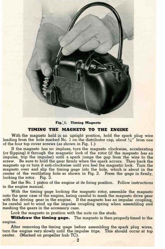
TIMING THE MAGNETO TO THE ENGINE With the magneto beld in an upright position, hold the spark plug wire
leading from the hole marked No. 1 on the distributor cap, about .!4'" from one of the four top cover screws (as shown in Fig. 1.)
If the magneto has no impiuse, turn tbe magneto clockwise. accelerating (or £lipping) it through the magnetic lock of the rotor (if the magneto has an impulse, t.rip the impulse) until a spark jumps the gap from the wire to the sc rew. Be sure to hold the gear firmly when the spark accurs. Then back the magneto up or turn it anti·clockwise until you feel the magnetic lock. Turn the magneto over and slip the timing gage into the hole, which is about in the cenler of the ventilating hole as shown in Fig . 2. Press the gage in firmly, locking the rolor. Fig. 3 .
Set the No. 1 piston of the engine at its firing position . Follow instructions in tbe engine manual.
With the timing gage locking the magneto rotor, assemble the magneto onto the gear case of the engine, being careful to mesb the magneto drive gear with the d riving gear in the engine . If the magneto has an impulse coupling, be careful not to wind up the impulse coupling spring when assembli ng and meshing tbe gears in the accessary case.
Lock the magneto in position with the nuts on the studs. Withdraw the tUning g a ge . The magneto is then properly timed to the
engine. Alter removing the timing gage before assembling the spa rk plug wires,
turn the engine very slowly until the impulse trips. This should OCCUI a t top ~nter. (Marked on propeller hub Te). _ 2

I
Fig. 2. Timmg Hole _d G.g.
The lag angle on this magneto is 30°. Check to see impulse trips freely to give a good starting spark. Should it
bind from interference with the cam gear, shim oul by placing extra gaskets on Dange 01 magneto, until you are positive it is free .
When assembling the spark plug, cables in the magneto distributor cap, be sure to push them down to the bottom of the holes. Holes No. 2 and No. 3 are 1; .. ... deeper than holes No. 1 and No. 4 . '(Holes are marked, see tFig. 1).
Should you not get the cables into the brass insert in the bottom of these holes, this would eventually burn through the distributor block insulation causing the engine to miss fire.
Fig. 3. TUniD.g O.ge in PJ;ace
I
'-Fi ... t . Sectional View of Milp eto
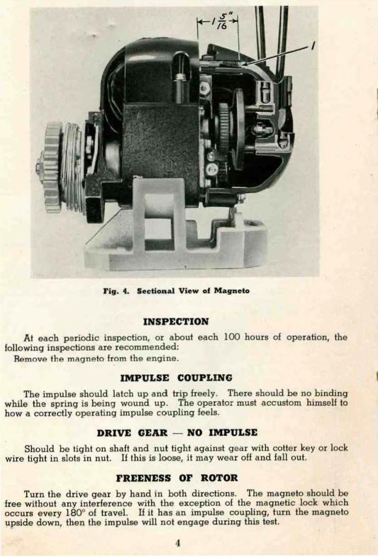
INSPECTION
At each periodic inspection, or about each 100 hours of operation, the following inspections are recommended:
Remov/) the magneto from the enoine.
IMPULSE COUPLING
The impulse should latch up and trip freely . There should be no binding while the spring is being wound up . The operator must accustom himselilo bow a correctly operating impulse coupling feels .
DRIVE GEAR - NO IMPULSE
Should be Ught on shaft and nut 11gh! against gear with coiter key or lock wire tight in slols in nut. II Ihis is loose, it may wear aU a nd fall out.
FREENESS OF ROTOR
Turn the drive gear by hand in both directions. The magneto should be free without any interference with the 9J:ception of the magnetic lock which occurs every 1800 of travel. If it has an impulse coupUng, turn the magneto upside down, then the impulse will nol engage during this test.
4
I
I
!
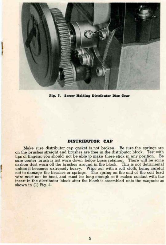
Fig. S. Screw Holdi.g D~trib.tor D~e Geaz
DISTRIBUTOR CAP
Make sure distributor cap gasket is not broken. Be sure the springs are on the brushes straight and brushES are free in the distributor block. Test with tips of fingers; you should not be able to make lhese stick in a ny position. Be sure cente r brush is nol worn down below brass re tainer. There wiU be some carbon dust worn aU the b rushes a round in Ihe block. This is not detrime ntal unless it becomes extre mely heavy . Wipe o ut with a soft cloth, being care ful nol 10 damage the brushes or springs. The spring on the e nd 01 the coil lead wire must not be bent, a nd must be long enough so it makes contact with the insert in the distribulor block afte r Ihe block is assembled onlo tbe mag ne lo as shown in (1 ) Fig. 4 .
5

Fig. 6. Me. hing Dilltributor Dille Ge ar.
DISTRIBUTOR DISC
DistTibutor Disc should be clean and smooth in the brush track. U there is an excessive black coating in this track, il can be removed with an ink eraser. Unless e xcessive, this is not harmful.
The screw shown in (Fig. 5) holds the distr ibutor disc shaft in the bearing. This prevents it from falling oul. Loosen this screw !16" (2 turns), to remove the disc.
When reassembling the disc, be sure the teeth of the gears a re meshed correctly . The tooth directly over the dot on the steel gear must be meshed between the two beveled teeth on the d istributor gear shown in (Fig. 6). The bevel on the two teeth on the canvas base Bakelite distributor gear must be on the side of the gear next 10 the distributor disc.
6
•

,
, Fiff. 7. Co"tac:t Pou..b
ADJUSTING CONTACT POINTS Slip the square pin of the timing gage inlo the hole in the rotor shaft as
seen through the ventilating hole in bottom of the magneto (Figs. 2 a nd 3). Tap it dow'n firmly so it locks the rotor. This is the position where the con· tacts should open.
With the distributor block and distributor disc olf the magneto, adj ust the sliding contact to a good full lace fit to the contact point on the breaker arm, with the points just bre5king about 0.001" to 0.002" . This can be checked with a Ihin piece of paper or cellophane, (see 1, Fig . 7) the same as you would check the magneto when timing on the engine. With the points adjusted correctly, lock the ad justable contac t in place, and the magneto is timed within itself to the gage.
Remove the timing gage; be sure the magneto is clean and reassemble the distributor disc and block.
7

OILING THE MAGNETO
The magnet rotor in this magneto is carried on two shielded ball bearings and requires no lubrication throughout the life of the bearings.
The Oilite distributor shaft bearing does not require oil as long as it is free. Should it become sluggish, clean and oil with one drop of light machine oil. Do not oil excessively.
Do not oil or grease the breaker cam. Oil, grease, or the fumes therefrom are very detrimental to contact point
life.
SERVICING MAGNETOS
Many Magnetos are ruined because they are tampered with by inexperienced operator's, under dirty, dusty conditions, or at places where proper service tools and testing equipment are not available.
Should your Magneto require attention other than that described herein, take it to one of the authorized Service Stations listed in our Magneto Service Station directory.
NOTE: No Warranty Service Work will be approved should it be done on a Case Aircraft Magneto by anyone other than an authorized Case Magneto Service Station or Case Magneto Depot Station as they have all the necessary tools and equipment to do this work in a satisfactory manner and are familiar with handling Magneto Warranty Service.
8

..... ·b" ..... 1",
•