case - nasa · analysis system (erl-das) for the ... thus it is necessary in the case of separate...
TRANSCRIPT

Final Report
EARTH RESOURCES DATA ANALYSIS SYSTEM
Contract No. NAS 9-12106
CASEPrepared for
NATIONAL AERONAUTICS AND SPACE ADMINISTRATIONManned Spacecraft Center
Facility and Laboratory Support BranchHouston, Texas 77058
1746FR-1 October 1972
A Z U S A . CALIFORNIA
https://ntrs.nasa.gov/search.jsp?R=19730007433 2018-06-21T20:41:15+00:00Z

Final Report
EARTH RESOURCES DATA ANALYSIS SYSTEM
Contract No. NAS 9-12106
1746FR-1
October 1972
Prepared for
NATIONAL AERONAUTICS AND SPACE ADMINISTRATIONManned Spacecraft Center
Facility and Laboratory Support BranchHouston, Texas 77058
Prepared by
AEROJET ELECTROSYSTEMS COMPANY1100 W. Hollyvale Street
Azusa, California 91702

1746FR-1
CONTENTS
SECTION 1 - INTRODUCTION 1-11. 1 Overview 1-11. 2 Physical Description 1-61.3 Program Chronological Summary 1-71.4 Acknowledgement . . . . 1-9
SECTION 2 - ERL-DAS SYSTEM 2-12.1 Computer System 2-32.2 The Multispectral Input System 2-32.2. 1 Input Data Capability 2-52. 2.2 Data Buffering 2-52.2. 3 Channel Enable 2-62. 2. 4 Overflow Indication and Output Transmission 2-62. 3 PCM and ADAS Interfaces . . 2-62.4 Bench Test Unit 2-72. 5 Optical Subsystem 2-82.6 Display Subsystem 2-10
SECTION 3 - ERL-DAS SOFTWARE 3-13. 1 The MSDS Programs 3-13.2 The SI 92 Processing Programs . . . ' . . . . . « 3-33. 3 The PMIS Processing Programs 3-53.4 The Optical Program (OSSS) Program Description 3-63. 5 Independent Handlers 3-7
SECTION 4 - APPLICABLE DOCUMENTATION 4-14. 1 Reference Documents 4-1
'. 4. 2 O&M Manual 4-1
SECTION 5 - ERL-DAS SPECIFICATION COMPLIANCE 5-1
SECTION 6 - CONCLUSIONS AND RECOMMENDATIONS 6-16. 1 Conclusions 6-16.2 Recommendations 6-1
11

1746FR-1
Section 1
INTRODUCTION
This document is the final report of the Earth Resources Laboratory
Data Analysis System (ERL-DAS), Contract No. NAS 9-12106. This effort
completes Article XIV. A. 2 of this contract.
The objectives of this contract were to design, fabricate, install and
verify operation of a data analysis system to be used for the processing, imag-
ing, and recording of Earth Resources Sensor Data.
Its principal applications include processing of 26 channel multispectral
data recorded on high density-PCM formatted analog tape, radiometric data ac-t*
quired by the Passive Microwave'Imaging System (PMIS), Skylab S192 data, and
multispectral data recorded on color or black and white film transparencies.
Computer software is included for operational processing of sensor input data
with versatile general handler packages suitable for system expansion. A
brief description of the ERL-DAS software is contained in Section 3 of this
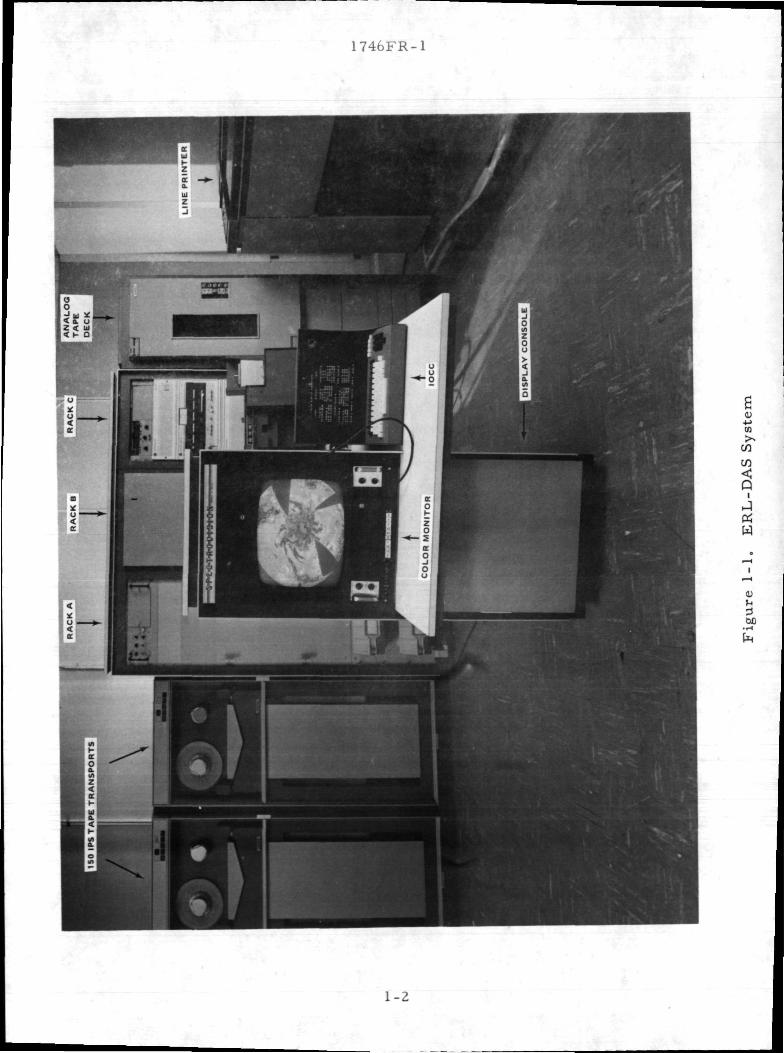
report. The ERL-DAS system (excluding the Optical Input System) is shown
in Figure 1-1.
1.1 OVERVIEW
On 29 June 1971 the Microwave Division of Aerojet-General Corpora-
tion initiated the design and fabrication of the Earth Resources Laboratory Data
Analysis System (ERL-DAS) for the National Aeronautics and Space Administra-
tion under Contract NAS 9-12106. The approach taken for this system empha-
sized versatility and flexibility so as to satisfy current and future data analysis
requirements. It incorporates innovative and imaginative concepts where these
can be implemented within well-established technology, and where practical
makes use of standard commercial products to minimize redundant design effort.
1-1
1746FR-1
CO<QJtfW
oc
1-2

1746FR-1
One source of earth resources data which must be processed by the
ERL-DAS is image data recorded on film. This data typically is multispectral
and is recorded either as separate black and white images, one for each spec-
tral band, or as one image on color film in which the film dyes contain the
spectral information. It is necessary to process this image information as
multispectral point-by-point data to support terrain signature analysis or image
enhancement processing. Thus it is necessary in the case of separate images
to precisely register each of the input films; and for the single color film to
separate'each spectral component from the film dyes. This subsystem must
be integrated into the overall DAS to serve as one of the data input sources.
There are several key aspects of the system design. An all-electronic
approach to the registration process is used which provides maximum flexibility,
offers significant simplification of the optical and mechanical sections, and
increased accuracy and reliability. The optics are implemented using a single
lens system and prism which has the attendant features of greatly simplified
alignment, high reliability-maintainability, and reduced cost.
Complete control of the scanning process is available to the data
analyst. Any type of scanning can be accomplished for automatic registration,
correlation studies, or the high-re solution digitization of a selected arbitrarily
shaped region such as a training sample area. Complete access to all output
devices and centralized control is provided by the interactive operator control
console (IOCC).3
A unique optical subsystem has been developed which incorporates
specially designed components in a novel arrangement that ensures optimum
system performance with a minimum amount of hardware. The subsystem
design is modular in the sense that components are combined in a subsystem
which is responsive to the subject system requirements. Provision for modi-
fication of components within the subsystem exists thereby allowing future
modification of the equipment for the execution of other related tasks. An
example of the modular structure of the subsystem is the ability to replace the
fixed magnification relay lens with a zoom lens to extend the range of the scanned
area below the inch-by-inch format.
1-3
1746FR-1
The magnetic tape input subsystem provides the ability to read the
13-channel, 10,000 bit-per-inch remote sensor data tapes, a single channel
PCM input, and the ADAS input. The design of this system is very similar to
the proven design developed by Aerojet for the PMIS-Data Analysis Station,
and its flexibility in handling a wide variety of data formats, including refor-
matted Skylab SI92 data has been established. This input system incorporates
those refinements and improvements typical of a second generation design after
hands-on operational experience.5
Control and monitoring of the Data Analysis System is accomplished
with the Model SG-D2400 high-speed data processor which includes options
tailored for this application, together with a tape search system and an inter-
active operator control console (IOCC).
All devices and interfaces which are controlled and monitored by
the processor, including the processor itself, are supported by complete
diagnostic routines for maintenance, adjustment, and troubleshooting use.
I/O handler packages which offer a clean interface, and where applicable,
linkage to the IOCC are provided for all devices. These handlers are assem-
bled, together with the necessary application and data dependent coding, to
form operational control and monitoring programs. The MOS operating system
supports batch processing operations and program access, which further
expands the flexibility of the system, and allows the use of the system for
secondary support activities.
The proper man-machine interface for the control and monitoring
of the Data Analysis System functions is a key to the successful operation of
the system. This interface provides a central point of control, easy input and
display of control and monitor parameters, interactive bidirectional responses,
and a high degree of flexibility to accomplish a wide variety of image process-
ing tasks. This capability is provided by the control panel concept offered by
the Model SG-D2500P Interactive Operator Control Console (IOCC).
The conventional approach to such a requirement is to provide an
assemblage of switches and lights. The rigidness of this approach is clear.
1-4

1746FR-1
The use of a serial character device such as a teletype or CRT terminal eases
the problem of communicating data values and alphanumeric data, but this
method is slow and awkward. The Aerojet IOCC provides a highly flexible
control panel which provides logically 800 switches, each of which can assume
one of 64 positions. Each such switch is displayed as a letter, character, or
iiumeral, and can be changed either by the operator or by the processor. The
entire display or selected portion, can be completely changed in less than a
second. Direct correspondence between the processor, the display, and the
keyboard marker assures absolute communications and rapid access to any
position.
\ Image data is displayed via the Aerojet Model SG-D 2116-P-M-L,
Displdy Unit which provides for the storage of a one-level image in addition
to the normal full color or pseudo-color image. This one-level image is
normally used as an overlay of the regular image. The spatial resolution of
this image is identical to that of the normal image. The SG-D 2116-P-M-L
Display units are supplied with a system to communicate between the one-
level image and the external data source, in this case the SG-D 2400 Data
Processor, optimized to provide a four corner, completely variable geometry
cursor with the minimum of information transfer. The resulting cursor frame
is one picture element wide by one TV line high. Complete spatial resolution
is provided with the transmission of less than 2000 nine-bit words. This com-
pares with the approximately 20, 000 words that would have to be transmitted
to define an entire single level image. The cursor is generated in the hard-
ware and stored on three additional tracks of the display disc memory. These
tracks are provided with flip-flop feed around so that cursor information appears
constantly on the screen during all cursor operations, without the annoying
flicker generated in the writing of a new cursor.
The intensity of the cursor outline is automatically adjusted in the
hardware to provide an optimum-contrast with surrounding scene data in true
color, pseudo-color and black and white display operating modes. The formu-
las used to perform this cursor intensity adjustment are as follows:
1-5

1746FR-1
A Model SG-D 2600 Strip Film Camera provides the ability to record
onto film, in either color or black and white, a high-resolution hard copy of
the digital image data processed by the Data Analysis System. The design
concept of this camera is based on the proven design used for the PMIS-DAS.
Adequate controls are included to adjust for any black and white or color film
of adequate sensitivity (Kodak 2448 Color Ektachrome and Acrographic Plus-X
are suitable).
1. 2 PHYSICAL DESCRIPTION
The separable physical entities of the ERL-DAS system are tabulated
below.
a. A three bay rack assembly consisting of the following, left to.right:
Rack A
• High resolution digitally driven color strip film recorder.
Rack B
• Multispectral PCM and ADAS input electronics
• Optical input system electronics
• Miscellaneous control and interface circuitry
• Power supplies
Rack C
• A Varian 62OF computer including the following subunits
• 16K core memory
• Two tape controllers
• Two buffer interlace controllers
• Two block transfer controllers
• Three priority interrupt modules
1-6

1746FR-1
• IRIG A time code reader and generator
• Expansion space
b. Two Ampex 150 IPS Tape Transports
c. A FR-2000 14 track wide band analog tape recorder/reproducer
d. One 300 cards/min card reader
e. A high resolution multispectral optical input system
f. A system control console consisting of the following:
• Color display
• IOCC alphanumeric display/keyboard
• Display/cursor-light pen electronics
• Miscellanceous interface electronics
g. A 64 character, 132 print position, high speed line printer
1.3 PROGRAM CHRONOLOGICAL SUMMARY
On 29 June 1971, the design and fabrication of the Earth Resources
Laboratory Data Analysis System was initiated.
A Design Review meeting was held at the Aerojet facilities on 19 and
20 August 1971 to discuss in detail the Design Review Report.
The detailed design of the optics portion of the ERL-DAS was presented
to NASA representatives during the design review meeting of 27 and 28 September
1971.; Software coding and hardware fabrication was continuing on schedule.
Preliminary checkout of the electronic subsystems was initiated during
the month of January 1972.
A meeting with NASA/MTF and their support personnel was held during
the month of February 1972 to clarify and agree upon the details of the Acceptance
Test Procedure previously submitted in rough draft form to NASA/MTF. Soft-
ware punching, assemblies and checkout were initiated during this month.
1-7

1746FR-1
During the month of March 1972 problems with the Varian CPU became
severe. Although problems could be worked around, the CPU problem caused
significant delay in program assemblies and checkout.
The preliminary acceptance test of the Multispectral Optical System
was performed at Perkin Elmer and the unit was installed at Aerojet1 s facility
during the month of April 1972. A significant portion of th6 hardware checkout
was completed.
A new data processor (CPU) and slave memory were installed in May
1972 due to Varian1 s inability to correct problems in the original CPU. Checkout
of essentially all hardware and a large portion of the software was completed
during this month.
The preliminary acceptance tests at the Aerojet facility began on 27
June 1972 and were completed on 1 July 1972. These tests were witnessed by
NASA MTF, Lockheed, AGC/QC, and DCASO representatives.
The ERL-DAS system was shipped to NASA MTF on July 7, 1972
and was received at MTF on July 10, 1972. Aerojet-General Corporation's
employees arrived at MTF July 11, 1972 and began system setup and checkout
in preparation for final acceptance testing. The system was operational July
12, 1972.
Acceptance testing of the ERL-DAS was conducted through July 22,
1972. The system was accepted with the specific exceptions noted on the
signed DD250. At this time a partial delivery was made of the supplementary
manuals of the O&M manual package.
Two (2) subsequent trips to NASA MTF by Aerojet and HRB Singer
personnel corrected the deficiencies noted in the DD250 obtained upon com-
pletion of the system acceptance test.
The O&M manual has been delivered to'NASA Houston completing
all requirements under Contract NAS 9-12106.
1-8
1746FR-1
1.4 , ACKNOWLEDGEMENT
Aerojet ElectroSystems Company wishes to acknowledge the invaluable
assistance provided by NASA technical and contract personnel in the successful
completion of the Earth Resources Laboratory-Data Analyses System contract
and extends special thanks to Messrs. Jim Derbonne, Bob Duppstadt, Bill Edwards,
Dave Harvey and Sid Whitley.
1-9

lYIb-b'R-l
Section 2
ERL, DAS SYSTEM
The Earth Resources Laboratory Data Analysis System is designed
with the capability to reduce a broad range of remote sensor data. The output
of the reduction operation may be presented in several different formats. The
system will accept sensor data that has been encoded using digital magnetic
tape, PCM encoded analog magnetic tape, including 24-channel multispectral
data, and photographic film, either black and white or color transparencies.
The system output may be recorded on digital tape for further proc-
essing, displayed on a high resolution color TV monitor, recorded on 9-1/2
inch color or black and white film or listed on a high-speed line printer. The
basic system includes the following major components.
a. A 14-channel broadband instrumentation tape reproducer/recorder.
b. A high-speed, general-purpose computer.
c. Two 150-ips digital tape recorders/reproducers.
d. A high resolution three-color TV display used to provideraster presentations of sensor data for evaluation by thesystem operator. Data may be presented in true color,pseudo color, or black and white. A light pen/cursorsystem is provided for delineation of data areas of interest.
e. A high-re solution, 9- I/ 2-inch -wide strip film camera sys-tem capable of recording on film data presentations in coloror black and white.
i
f. A versatile Interactive Operator Control Console providingcomplete operator-processor communication and control.
g. A multispectral optical input subsystem capable of high-resolution scanning and digitizing of black and white multi-spectral transparencies or color transparencies.
2-1
1746FR-1
These major system components are coupled to the high-speed,
general-purpose computer through specially designed interface units designed
for maximum data transfer rate, with the minimum of software monitoring
required for their operation.
The 14-channel broadband instrumentation tape reproducer/
recorder is a 1-inch tape Ampex FR-2000 with a set of direct playback elec-
tronics and the associated equalizing networks to allow the playback at tape
speeds from 1-7/8 to 120 inches per second. In addition, there is one (1) set of
direct record electronics that may be used with the Tench Test Unit to gen-
erate analog tapes in selected data formats. The FR-2000 is also equipped
with a servo speed control to play back data tapes at continuously variable
tape speeds, and to allow matching of the data input rate to the data reduction
processing speed.
The high-speed, general-purpose computer is a Varian Model 620F,
16-bit word length, equipped with two (2) Buffer Interface Controllers, (2}Block
Transfer Controllers, two (2) 9-track 150 ips tape controllers and 16, 000 words
of memory. An optional instruction set including a hardware multiply/divide
capability is included. A high-speed line printer and 300 card/min. card
reader and required controllers are also included in the computer subsystem.
The three-color TV display system uses a Conrac 19-inch RGB
monitor with a 48-track data disc memory unit which is used for monitor dis-
play, refresh. The display refresh memory provides a constant flicker-free
presentation of the displayed data by providing the color or black and white
information at standard television line and field rates. The combination of
the computer and the data disc memory provides a completely flexible scan
conversion system which presents the data at a standard television rate
regardless of the scan rate used when the data was acquired.
The display system is implemented to provide an overriding cursor.
The cursor information is stored on the data disc memory on tracks separate
from the image data thus leaving the original image data intact. Control of
the cursor size and position on the screen may be obtained from input from
the numeric display keyboard. In addition, movement and modification of the
cursor corners may also be accomplished utilizing a light pen interface.
2-2

1746FR-1
The multispectral optical system consists of a high-resolution Beta
Instrument flying-spot scanner, control electronics and a Perkin-Elmer multi-
spectral optical subsystem. The optical subsystem accepts up to four (4) black
and white film transparencies or one (1) color transparency with the required
optics to separate the color transparency into RGB data. Data is digitized to
one (1) part in 1023 (10 bits).f
Figure 2-1 is a block diagram of the ERL DAS system showing
input/output and subsystem signal flow.
2.1 COMPUTER SYSTEM
'The Varian 620F computer system consists of a main frame and
two (2) expansion chassis. The system contains the following features.
a. 16 K memory.
b. Optional instruction set including hard-wire multiply anddivide capability.
c. Two (2) Buffer Interface Controllers providing automaticI/O transfer.
d. Two (2) Block Transfer Controllers providing high-speeddirect I/O transfer with memory.
e. Two (2) TM16 9-track tape transports and controllers pro-viding tape speed of 150 ips at 800 bpi (12 kHz transfer rate).
f. One (1) 300-card-per-minute card reader and controller,,
g. One (1) high-speed line printer and controller providing132 columns, 64 characters at a rate of 245 to 1100 linesper minute.
h. Three (3) 8-level priority interrupt modules.
2.2 THE MULTISPECTRAL INPUT SYSTEM
The multispectral data is recorded on 14 tracks by a magnetic tape
recorder. Thirteen (13) of these tracks may be read at one time by the interface
system. Twelve (12) of these tracks contain two (2) sensor values each, and these
2-3

1746FR-1
3 SS '
^
t' -,
OS |
f I-- a
1 I0" 8
o1L-
S5
IOJL- fs
3E
o c o f~ !><'S.-cu: o o-•O
•? =o S
K V
±;oa: a*- e
J
sS » 8P ? a
SCO
9
"-5..o S-
&0
•t-f
Q
oo
Siu
Q. O>
S fs *"CVJ eO
O .ii
6 g*«n -"
fe 8O m
o
U
0)
fe i
a. —» ,A^ ca
•c eK3
f83o
Q
W
s §-
o- .".
^ C0
2-4
1746FR-1
sensor values-are time-division multiplexed. One (1) track contains instrumenta-
tion support data. These 13 tracks are always recorded by the Multispectral
Scanner System at a density of 10, 000 bits per inch./ Each of these 13 channels
are modulated with bi-phase L pulse-code modulation. A data value is madei ''. . r
up using eight (8) sequential bits. These eight (8) sequential bits become a sensor
word. There is a specific 16-bit frame sync pattern that appears once every
1572 words and corresponds to the starting point of the multispectral scan.
The fourteenth channel contains an IRIG standard time code. This time code
is used by the ERL-DAS for tape search purposes. The salient features of
the ERL-DAS MSDS Input Subsystem are listed below.
2. 2. 1 INPUT DATA CAPABILITY
a. Thirteen .(13) separate input channels are provided, each capableof operating from, a PCM input encoded in Bi-phase L.
b. All channels are capable of acquiring and locking onto the' data at any bit rate from 10 kbps to 200 kbps and 350 to 750
kbps.
c. The foregoing bit ranges are covered by 5 separate bit syn-chronizers. Selection of the bit synchronizers and bit syn-chronizer center frequencies are remotely programmable tothe required resolution via digital logic signals. Selectionalso commands the FR2000 tape recorder to the correct speedfor the 10, 000 bpi density.
d. Proper operation of the subsystem requires the successfuldetection of a 16-bit frame sync pattern for each enabledinput channel. The appropriate 16-bit sync pattern is alwaysthe same for each input channel, but the basic sync patternis defined by a 16-bit word supplied by the data processorand is completely variable.
2. 2. 2 DATA BUFFERING
a. Each channel is provided with a total of 64 bits of buffercapacity. Sixty-four bits allow the reception, in a givenchannel, of a total 79 bits of skew before the bufferingcapacity is overloaded.
2-5
1746FR-1
4^.. b. Loading of the buffer section of each channel is independent\ of all other channels and commences when the appropriate
16 -bit sync pattern defined by the output from the dataprocessor. is detected by the channel logic.
2. 2. 3 CHANNEL ENABLE ,
a. Each of the 13 input channels may be remotely enabled byi digital logic.
. b; ; A signal jis generated by each channel, •which may be remotelysensed, and indicates the successful acquisition of the appro-priate frame sync by the channel.
c< A signal is generated by the subsystem indicating when allenabled channels have successfully transferred the first dataword of the first acquired frame.
dv A signal is reissued as all enabled channels have receivedeach additional word.
2. 2. 4 OVERFLOW INDICATION AND OUTPUT TRANSMISSION
av The subsystem acknowledges the transmission to an externaldevice of the data stored in one section of the data buffer byeffectively clearing that section of the buffer and allowing newdata to be stored.
b» If the external device does not withdraw the data from thechannel buffer within the allowed bit times, an overflowindication is supplied by each channel.
To minimize data manipulation and increase system throughput,
each channel may be selectively enabled to transfer either one or both eight-
bit values of a 16-bit input wofrd. Only those channels so enabled are trans-
mitted thereby minimizing the data transfer operations.
2. 3 PCM AND ADAS INTERFACESt '
The PCM input interface provides the capability to process a wide
variety of PCM recorded data. This interface providest
a. Input of one, -.(I) channel of PCM data at any data rates^'from180 to 100, 000 bps using 10 independent bit synchronizers.
2-6
1746FR-1
b. Data processor selection of the bit synchronizer and the 2:1fine adjustment of center frequency independent of tape repro-duce speed.
c. Data transfer of any word length from 5 to 16 bits with dynamicdata processor selection of word length.
d. Data transfer by programmed control or by automatic blocktransfer using the high-speed priority channel.
e. Highly flexible sync and de com mutation of the data in asso-ciation with the processor.
The ADAS input is required to provide the housekeeping data, such
as time, aircraft parameters, and status which are used by some of the data
collection systems. This subsystem will acquire, decode, pack, input and
list ADAS data reproduced from the FR2000 analog magnetic tape in the FM
Wideband II mode. The input rate can be adjusted from 12. 5 to 25 K bits/sec
(nominal is 23 K bps) with automatic thresholding of the frame sync pulse.
Data transfer is by programmed control with transfer initiated by a frame
sync interrupt and a data word available interrupt.
2.4 BENCH TEST UNIT
Checkout and verification of the PCM inputs to the ERL-DAS requires
a device which can generate the desired test signals both to test and adjust the
hardware and to create analog test tapes. This unit provides:
a. Thirteen (13) parallel outputs with line drivers.
b. ' Output encoding of the test data as bi-phase L, RZ, or NRZas selected by digital logic signals.
c. Data rates from 146. 5 to 1, 200, 000 bps as selected by logicsignals.
d. Any desired bit pattern, either cyclic or dynamically varying.
e. Automatic block data transfer so the processor is availablefor other tasks.
2-7
1746FR-1
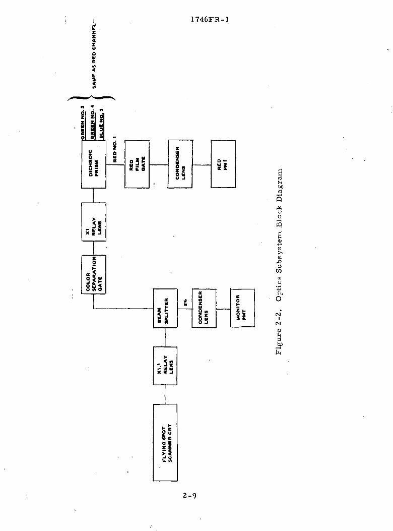
2. 5 OPTICAL SUBSYSTEM
2. 5. 1 OPTICS
The optical subsystem receives the light from the spot illuminated
on the flying spot scanner (FSS) and transmits this light through the film to the
photomultiplier pickups. The optic subsystem can be used, depending upon the
placement of the film, either to scan up to four film images (black and white)
or to separate the dye layers of color film into the spectral components of red,
green, and blue. The optics subsystem, shown in Figure 2-2, consists of the
following components:
a. Color Separation Lens. This lens projects the light throughthe beamsplitter onto the color separation film gate. Thislens also provides the 1. 1 magnification to match the FSSsize to the film sizes.
b. Beamsplitter. This beamsplitter intercepts the unmodulatedlight and transfers approximately 8 percent of the luminanceto the reference PMT. This measure allows the electronicsto compensate for variations in source illuminance.
c. Color Separation Gate. In color separation operations, thecolor film located at this point is scanned by the FSS. Thisgate is left open when multi-image registration is used.
d. Relay Lens. The relay lens couples the light with the beam-splitter prism with unity magnification.
e. Prism. The prism separates the incident light into fourseparate displaced images in which each image contains adiscrete portion of the incident spectral energy, thus facili-tating both color separation and multi-image scanning. Theprism reflects the blue component of light at the first beam-splitting surface with a blue reflecting dichroic interferencefilter, subsequently reflects the red component at the secondbeamsplitting surface with a red reflecting dichroic, andfinally divides the green components into two equal intensitychannels with a neutral density beamsplitter located at thethird beamsplitting surface.
f. Film Gates. The four (4) separate images generated in theprism are imaged onto the film gates when multiband opera-tion is used.
g. Condenser Lenses. The condenser lenses couple the modu-lated light from each of the film gates to the PMT's.
2-8
i
Id
OO
1746FR-1
$III
bflnl
Oi— icq
s0)
•4->w>vW
inO
• r-l
(MI
Vi-i•3tuo
£ oM K
ii
2-9

1746FR-1
2. 5. 2 OPTICAL, ELECTRONICS SUBSYSTEM
The photographic electronic subsystem, under direction of the data
processor, generates a precise optical input scan to the flying spot scanner
(FSS) and receives the resultant output with photomultiplier tubes (PMT). It
provides the control and data handling necessary to register one (1) to three
film images to a reference image, and to scan digitize automatically the images
to a high degree of accuracy following registration.
System scanning parameters are entered into the optical input elec-
tronics by means of the computer BIC buss. When used in conjunction with
the OSSS software, the scanning parameters are operator-controllable from
the IOCC.
2. 6 DISPLAY SUBSYSTEM
The display subsystem consists of the following units:
a. Five-bit true color, 6-bit pseudo color, high-resolutionTV display.
b. High-resolution strip film recorder option.
c. Cursor, light pen, and light pen target option.
d. Interactive Operator Control Console option.
2. 6. 1 TV DISPLAY
The TV display provides the capability of presenting digitally
encoded data in high resolution images of pseudo color, true color or black
and white. Changeover in operation between the pseudo-color and five-color
modes is simply accomplished by changing a logic patch card.
The TV display consists of input buffer storage, a 3: 1 write multi-
plexer, real time disc storage of 525 data lines, a 3:1 read multiplexer,
color algorithm memories, test pattern generators, video D-A converters,
timing logic and a 19-inch Conrac color monitor. Input storage consists of
135, 64-bit MOS shift registers. It provides storage of one complete display
2-10

1746FR-1
line, 576 pixels with 15 bits per pixel. Under computer control, this input
storage register may be loaded with up to 558 pixels asynchronous with the
display timing. Upon load completion the line contents are then written on
the disc at the line address previously transmitted by the processor on the
input data lines. The 135, 1 Mbps shift register outputs are multiplexed to
45 write outputs providing a 3-Mbps data rate to the disc tracks. The disc
provides real time storage of 525 data lines. Disc revolution is synchronous
to the color monitor frame rate of 30 frames per second. Reading off the
disc the 45 data lines are further multiplexed to provide 15 lines at 9 Mbps
data rate per line. These 15 lines are applied directly to the three-color D-A
converters (5 bits/converter) in the true color mode, or six of the fifteen
lines are used as address information to the color algorithm memories,
providing 64 colors, as described in the algorithm memories in the pseudo-
color mode. The color algorithm is loaded into the memories either under
computer control or manually by front panel switches. Black and white is
provided by slaving the red and blue D-A converters to the green D-A con-
verter. In the black and white mode, the green D-A input is derived directly
from disc output only (the same six lines used as address lines to the color
algorithm memories in the pseudo-color mode). In addition to normal data
presentation, test pattern generators are available to provide data, bars,
gray scale or a presentation of the color values stored in the color algorithm
memories. The timing logic generates the horizontal and vertical scan rates
and their associated sync pulses from the disc clock output. In addition, it
synchronizes all functions of the display subsystem. The three D-A con-
verters providing green, red, and blue video to the monitor have a response
in excess of 20 Mbps. The Conrac monitor video response is in excess of
7 MHz.
The characteristics of the TV display are listed below:
• 525-line frame
• 30 frames/second
• 576 pixels/line
2-11

1746FR-1
• 15 bits/pixel (6 bits black and white)
' • 500 displayed pixels/line
• Asynchronous computer-controlled loading
• Input buffer capacity = 1 line (576 pixels)
• Rising raster, falling raster, single line update or fixedraster
• Maximum load rate — 60 lines/sec, 1 Mbps asynchronous/input data line
• Simultaneous presentation of 64 pseudo colors
• Selection of 4096 color hues/pseudo color
• Capability of presenting up to 2 colors in true color
• Color algorithm loadable either under computer control orfrom front panel switches
• Test Patterns — dots, bars, gray scale, contents of coloralgorithm memory
• Video Response — 7 MHz
2. 6. 2 CURSOR/LIGHT PEN OPTION
The display subsystem provides for the storage of one-level image
in addition to the normal full color or pseudo-color image. This one-level
image is used to provide a four-corner, completely variable geometry cursor
overlay. The cursor frame is one picture element wide by one TV line high.
Complete spatial resolution is provided with the transmission of less than
2000 nine-bit words. The cursor is generated in the hardware and stored on
three additional tracks of the display disc memory. These tracks are pro-
vided with,flip-flop feed-around so that cursor information appears constantly
on the screen during all cursor operations.
The intensity of the cursor outline is automatically adjusted in the
hardware to provide an optimum contrast with surrounding scene data in true
color, pseudo color and black and white display operating modes. The for -
mulas used to perform this cursor intensity adjustment is as follows:
2-12

1746FR-1
If a given picture element on the screen is to be displayed as a
cursor outline point, the values of the associated normal display picture ele-
ment are examined as to intensity. If the most significant bit of any two .
colors is true, the cursor produces a full black picture element on the screen.
If neither bit is true, the cursor produces a full white picture element on the
screen.
The technique of storing the cursor information on the same stor-
age disc used for the image guarantees precise image/cursor registration in
all modes of display operation including falling or rising raster modes and
allows processor routines to provide the necessary data manipulation to pro-
duce data zoom and other desired cursor functions without additional param-
eter inputs.
There are two modes of cursor operation: (1) move existing cursor
and (2) modify cursor shape and size. Either mode can be used at any time.
The actual operation of the cursor definition and positioning pro-
ceeds as follows. The operator commands the overall system onto the cur-
sor operating mode by means of the IOCC. He then selects, again by means
of the IOCC, in which of the two modes he wishes to operate. When first
commanded into cursor mode, the data processor will instantly produce a cur-
sor approximately 2 inches square in the center of the screen. The operator
applies the light pen to the center of the cursor area and presses a button on
the body of the light pen. At that time, a special symbol called the light pen
target, will appear in the center of the cursor area. The location of the light
pen target is defined by two 9-bit words transmitted from the data processor.
The target is a bright white square made up of 8 picture elements wide by 8
TV lines high. This square will always be full white in intensity. Surround-
ing this white square will be an area that will always be full black. The width
of the black area is 2 pixels on each side of the square and 2 TV lines on top
and bottom. This combination assures that the light pen target will always be
detectable no matter what the basic image content is on the screen of the dis-
play. The light pen will pick up information from an area of approximately
one picture element wide by one TV line high.
2-13
1746FR-1
In the move cursor mode, the data processor is alerted to the posi-
tion of the light pen in the light pen target. The data processor then recalcu-
lates the cursor and target position and outputs this information to the hardware
cursor generator. The square and cursor appear to follow the movement of the
light pen and the operator can position the cursor to any location on the screen
by "dragging" the light pen target in the direction of desired movement.
In the cursor modify mode, the operator again applies his light pen
to the center of the cursor area. When he presses the switch on the light pen,
the light pen symbol appears. As he moves the light pen in this mode, the
symbol follows but the cursor remains stationary. When the symbol meets
one of the corners of the cursor, that corner of the cursor will move in the
direction of travel of the light pen target as controlled by the light pen. Once
he has established the proper position for this .line, he releases his light pen
switch. When he reinitiates the light pen switch the light pen target will appear
in the center of the new cursor area. The operator may then move the light
pen target to any other corner of the cursor and selectively modify as required.
There is no restriction on either movement or modify sequences and the oper-
ator may perform the appropriate tasks in any manner he desires. The com-
puter will respond to any target hits that occur while the switch is depressed.
If the operator moves the light pen too fast for the data processor to follow,
the light pen target will stop at the last location, if no other target hits occur,
and the operator need only return the pen to the target to continue on. The
speed of the system in all cases is such that the operator can view the progress
of the cursor movements. The reliability and accuracy of the light pen cursor
control system is equal to that obtained with X, Y corner position entry using
the IOCC unit.
2. 6. 3 HIGH RESOLUTION STRIP FILM CAMERA
The high resolution strip film camera provides the following
characteristics:
• Simultaneous operation with the companion color displaysystem, thus minimizing the data transfers required andproviding a monitor of the data being recorded.
2-14

1746FR-1
• Film width of 9-1/2 inches. Film length of 200 feet.Mountable film cassettes for easy film switching.
'• Black and white or color film.
• Brightness resolution of 32 levels for each of the threeprimary colors. Spatial resolution of 2400 elements in o9 inches with a 1:1 "square" aspect ratio.
• Writing rate of 30 lines/sec in black and white and 10lines/sec in color for any line length.
• Mode selection and synchronization with the displayaccomplished with digital logic signals.
2. 6. 4 INTERACTIVE OPERATOR CONTROL CONSOLE (IOCC)
The proper man-machine interface for the control and monitoring
of the Data Analysis System functions is a key to the successful operation of
the system. This interface provides a central point of control, easy input
and display of control and monitor parameters, interactive bidirectional
responses, and a high degree of flexibility to accomplish a wide variety of
image processing tasks. This capability is provided by the control panel of
the Interactive Operator Control Console (IOCC).
The IOCC provides a highly flexible control panel which provides
logically 800 switches, each of which can assume one of 64 positions. Each
such switch is displayed as a letter, character, or numeral, and can be
changed either by the operator or by the processor. The entire display, or
selected portion, can be completely changed by the processor in less than a
second. Direct correspondence between the processor, the display, and the
keyboard marker assures absolute communications and rapid access to any
position.
The display area in operation is typically divided into areas of
labelled control input values, which provide an operator checklist, labelled
data values (which provide monitoring), error message output or identifica-
tion input, and operator mode selection and status display output. The IOCC
automatically corrects illegal operator requests or entries, which provide
2-15
1746FR-1
both prompting for the operator and security of the displayed control panel.
In the upward scroll mode, the IOCC serves as a direct replacement for the
typical teletype operation, and thus supports coding previously developed for
ASR33 operation. Included on the keyboard of the IOCC are 12 action-initiator
switches which interface directly with the processor and interface logic.
2-16
1746FR-1
Section 3
ERL-DAS SOFTWARE
3. 1 THE MSDS PROGRAMS
Digital image data from the MSDS multispectral scanner is recorded
in the aircraft onto analog magnetic tape in a 14-track format. On each of the
MSS data- channels, tracks one to twelve, two spectral channels are recorded
per track. Track thirteen contains housekeeping data and track fourteen con-
tains an IRIG-A time code corresponding to the time of recording.
A software system for use with the ERL-DAS has been developed
to process this image data into a form useful to scientific investigators. The
principal tasks include the following:
• Quick-look color display of the data
• Copy of selected portions of the data onto computer-compatibledigital magnetic tape for use in subsequent detailed analysis
• Select training samples from the displayed test areas
Three separate programs are used to accomplish these tasks - the
MDCV, TSMS, and TCMS programs.
3.1.1 MDCV (DATA CONVERT) PROGRAM DESCRIPTION
The MDCV program is the first step in the processing of the MSDS
image data to yield a quick-look display of the images and support training
sample selection.
This program operates on MSS sensor data to produce quick-look
image displays and to produce formatted digital data tapes containing image
information. The data source is the twenty-six channel, multiplexed, fourteen
track magnetic tape, which is recorded at a constant density of 10, 000 bits/
inch. In addition to the digital recording and display of data, the MDCV program
3-1
1746FR-1«
IK used to (1) select a £et of up to twenty-four image channels, (2) logically
combine them into one channel, and (3) display and/or record, the resulting
data.
The image displayed will be the image selected, during the image-
selection operation, and will be converted to color either directly as part of the
selection operation or by a color scale in the display routine. This display can
embrace any portion (at full resolution) of the image.
3. 1. 2 TSMS (TRAINING SAMPLE SELECT) PROGRAM DESCRIPTION
The TSMS program is an image display program which uses an image
input tape, the color strip film'camera, the color monitor, the cursor hardware,
the line printer, the IOCC and the Varian 620/f (16K words). Program control
is implemented through the Interactive Operator Control Console (IOCC) sub-
system, and. complete control of input, image manipulation, display/record,
and output may be exercised from the console.
This program takes image data recorded on digital tape, processes
this data, and presents the data to the color display and. strip film recorder.
Training samples can be identified and selected with the cursor on the display.
This data is saved for subsequent use by the TCMS program.
The program includes a complete color study routine to modify color
scales, a cursor display package to delineate sub-areas of special interest, and
a training sample print and tape write routine to record the coordinates of these
sub-areas.
3. 1. 3 TCMS (TAPE COPY) PROGRAM DESCRIPTION
The Tape Copy (TCMS) program is used to read the 26 channel/
multiplexed 13-track analog MSDS data tapes and record the data on digital tape
for subsequent processing. The multiplexed thirteen track analog tapes are re-
corded a constant bit density of 10, 000 bits per inch per channel. For MSDS
data this is about 16, 200 data words per inch and at a playback rate of 3"/sec is
48, 000 data words/sec.
3-2

1746FR-1
For optimal utilization of the MS data the MDCV and TSMS programs
may be used, to identify areas of interest to be copied on digital tape for further
processing. The TCMS program finds the requested interval on the analog tape
and cdpies out that portion of the data. IOCC control allows the selection of MS
scanner channels to be copied.
3. 2 THE SI92 PROCESSING PROGRAMS
Image data from the source tape is recorded, on PCM encoded analog
tape by the Data reformatter assembly. A software system for use with the
ERL-DAS has been developed to process this image data into a form useful for
scientific investigators. The principal tasks include the following:
• Quick-look color display of the data
• Correction of geometric distortion
• Select training samples from the displayed, test areas,
• Copy of selected portions of the data onto computer compatibledigital magnetic tape for use in subsequent data analysis.
Four programs are used to accomplish these tasks: the SDCV, SCOR,
TSSL and TCSL.
3.2.1 SDCV (DATA CONVERT) PROGRAM DESCRIPTIONI
The SDCV program is the first step in the processing of the SI92
image data to yield scan-converted display of the images and support training
sample selection./
This program operates on SI 92 sensor data to produce quick-look
image displays and to produce formatted digital data tapes containing image
information. The data source is the twenty-six channel, multiplexed, four-
teen track magnetic tape, which is recorded at a constant density of 10, 000
bits/inch.
3-3

1746FR-1I.
•
In addition to the digital recording and display of data, the SDCV pro-
gram is used to (1) select a set of up to twenty-four image channels, (2) logically
combine them into one channel, and (3) correct the input channel scans for geo-
metric distortion. The distortion correction function is described in detail in
the section entitled The Scan Correction Program.
3. 2. 2 SCOR (SCAN CORRECTION) PROGRAM DESCRIPTION
The SCOR program provides the link between the Data Convert and! !
the Training Sample Select programs to complete the scan conversion process
for the SI92 image data. The two data tapes produced by the SDCV program
must be processed to produce the TSSL input tapes. In two separate operations
the center and the edge data (each recorded on a magnetic tape) are converted
to yield the two output magnetic tapes.
This requires reading the SDCV produced tapes, completing the SI 92
scan correction, reformatting and writing two output tapes which will be used
by the TSSL program for display and selection of training samples.
3. 2. 3 TSSL (TRAINING SAMPLE SELECT)
The TSSL program is an image display program which uses two image
input tapes, the color strip film camera, the color monitor, the cursor hardware,
the line printer, the IOCC and the Varian 620/f (16K words). Program control
is implemented through the Interactive Operator Control Console (IOCC) sub-
system, and complete control of input, image manipulation, display/record, and
output may be exercised from the console.
This program takes image data recorded on two digital tapes, merges
and processes this data, and presents the data to the color display and strip film
recorder. Training samples can be identified and selected with the cursor on the
display. This data is saved for subsequent use by the TCSL program../
The program includes a complete color study routine to modify color
scales, a cursor display package to delineate sub-areas of special interest, and
a training sample print routine to record the coordinates of these sub-areas.
3-4

1746FR-1
3.2.4 ; TCSL (TAPE COPY) PROGRAM DESCRIPTION
The Tape Copy (TCSL) program is used to read the 26 channel/
multiplexed 13-channel analog S192 data tapes and record the data on digital
tape for subsequent processing. The multiplexed thirteen channel analog tapes
are recorded a constant bit density of 10, 000 bits per inch per channel. For
S192 data this is about 17, 500 data words per inch and at a playback rate of
6"/sec is 105, 000 data words/sec.
For. optimal utilization of S192 data, the SDCV, SCOR and TSSL pro-
grams may be used to identify data areas of interest to be copied on digital tape.H ; • •
The TCSL program finds the requested interval on the analog tape and copies
out that portion of data. IOCC control allows the selection of SI 92 channels to
be copied1.
3. 3 THE PMIS PROCESSING PROGRAMS
The ERL-DAS has two major computer programs to process data from
the Passive Microwave Imaging System (PMIS). These are PMIS DATA convert and
PMIS DATA select.
3. 3. 1 PMIS DATA CONVERT
The Data Convert Program extracts pertinent data from the PMIS PCM
input bit stream, the ADAS input bit stream and the IRIG-A time code channel.
The output consists of either scan or temperature-map digital tapes for subsequent
analysis by the PMIS Data Select Program, a real-time CRT image display, a
real-time numeric display of support data and real time ADAS data line printer
listings.
This program is an operator-oriented extraction program which reads
PMIS data from an FR2000 analog tape drive and writes the data on digital tape.
CONVERT also allows display of microwave radiometer image data on a color
CRT and display of system parameters and support data on a numeric CRT. The
data copied onto the digital tape contains all essential information from the
separate input data streams and is corrected for all geometric and radiometric
errors.
3-5
• 1746FR-1
( - ';
3. 3. 2 THE PMIS DATA SELECT PROGRAM
The Data Select program processes digital tapes created by the PMIS
Data Convert Program, displaying and/or recording annotated, images while
simultaneously supplying all support data to the operator on the numeric display.
I/O hardware utilized by the SELECT program consists of only five
devices. Data is input from the right-hand digital tape drive. Control variables
are set in the program by the operator through the numeric display. Image data,
together with the associated color scales and support annotation, is output to the
color CRT and/or the strip-film color recorder. The system parameters, in-
cluding scan number, time and so forth, are output to the numeric display. Lastly,
the color CRT cursor hardware is used by the program to enclose areas of interest
specified by the operator.
A number of display options are available to the operator. Data can be
displayed either in black and white or color images in one field or three fields.
Selected brightness temperature ranges can be displayed independently in each
of the three fields. Data in any given field can be fitted to any one of eight separate
color tables. Each field can be set to display microwave data in any one of four
standard modes - vertical brightness temperature (V), horizontal brightness tem-
perature (H), the average of the two brightness temperatures (A) and the difference
between the vertical and horizontal brightness temperatures. In addition, any por-
tion of the display which is surrounded by the CRT cursor may be expanded to
fill the entire screen.
3.4 THE OPTICAL PROGRAM (OSSS) PROGRAM DESCRIPTION
The optical processing program, OSSS, provides the processing func-
tions associated with the multiband optical input subsystem (MOS) of the Earth
Resources Laboratory Data Analysis Station ERL-DAS. The input of scanned
image data from, up to four film gates, the registration of two images, the color
separation of a color transparency, and the output of this image data onto
computer-compatible magnetic tape, color display, and color film recorder are
supported.
3-6

1746FR-1
All the control and processing functions for the input and output of
optical images are supported by the OSSS program. The MOS system can scan
and digitize up to four film gates over a format size of 1 x 1 inch to 4. 5 x 4. 5
inches. The 1023 x 10Z3 raster scan can be placed anywhere in the 4. 5 x 4. 5
inch format. The input data can be electronically registered during the scanning
process such that the digital data from the MOS is in register upon entry to the
computer. The data from the MOS is presented first in the sequence of the film
gates chosen (these may be any order chosen), then in sequence of the horizontal
positions starting at the left side of the raster, and then in sequence of the hori-
zontal lines starting at the top of the raster.
The program, has two principal operating modes - the sequence mode
and the registration moder-using the IOCC to select all parameters. After the
appropriate interrupt switch is depressed, the program, first sets up the MOS
electronics from the parameter input from the IOCC, then sequentially collects
the horizontal lines. Each line is processed as requested and then sent to the
selected output devices - the color display, film recorder and magnetic tape.
In the sequence mode, the data from up to the first three film gates
are used for the green, red and blue channels of the display or recorder. In the
registration mode, the standard (reference) film gate is displayed in green and
the image to be registered is displayed in red facilitating selection of IOCC
registration parameters.
A software correction for optics vignetting and non-uniformity is
included in the program.
3. 5 INDEPENDENT HANDLERS
The ERL-DAS software system provides several independent handlers
which are incorporated into the main ERL-DAS program or may be utilized in
expansion programs.
3. 5. 1 THE INTERACTIVE OPERATOR CONTROL CONSOLE (IOCC) HANDLER
The Interactive Operator Control Console Numeric Display Handler is
a general purpose I/O control package of the Earth Resources Laboratory Data
3-7

1746FR-1
Data Analysis Station system software. It is designed to completely handle
numeric communication with the operator/user on a demand-only interrupt
basis.
The handler communicates directly with the Beehive Instruments
numeric display using interrupt levels three and four in Priority Interrupt
Module Two as input and output interrupts, respectively. Control of the I/O
is accomplished according to externally defined tables.
The Input Interrupt Subroutine allows selected operator input to
change control data values of various formats, including special formats which
are defined by external special subroutines.
The Output Interrupt Subroutine handles the maintenance of output
interrupt sequences as generated by the user program. The numeric display
screen consists of twenty lines of forty characters each. If a given line has
no new characters to be updated the Output Interrupt Subroutine skips that
line and goes onto the next. Upon completion of the output update sequence,
the Output Interrupt Subroutine returns the numeric display cursor to the lo-
cation on the screen at which it previously resided. The Input Interrupt Sub-
routine is inhibited during all output interrupt sequences; any input requests
received during an output sequence are saved until the output sequence is
completed and are then processed.
The Output Sequence Start Subroutine generates output update se-
quences according to control parameters passed as arguments in the call
statement. Where appropriate, it clears the numeric display screen at the
start of the output update sequence. Updates of any single line, any sequential
group of lines, or the entire screen of twenty lines are allowable.
3.5.2 ADAS INPUT HANDLER
The ADAS input handler is a general purpose utility package of the
Earth Resources Laboratory Data Analysis Station System software. Data
from the ADAS input bitstream is decoded and assembled into binary words
which are externally available to the user program.
3-8

1746FR-1
j
The Handler interprets ADAS data consisting of 96 character frames
input to the computer in 24 four-character words forty times every second.
Interrupt levels 1 and 2 in Priority Interrupt Module No. 1 are used as the ADAS
Work and Sync Interrupts, respectively. There are twenty-four word-interrupts
between each sync interrupt.
3. 5. 3, THE CURSOR LIGHT PEN HANDLER
The Cursor/Light Pen Handler is an independent software package
designed to support the light pen I/O hardware and the CRT cursor hardware of
the Earth Resources Laboratory Data Analysis Station. It can be connected by
the user program to any one of the eight interrupt switches on the numeric dis-
play console. ;
The handler fully supports the light pen I/O hardware and the cursor
hardware. The cursor portion extracts the cursor corner coordinate data from
an externally defined buffer, assembles a cursor overlay and outputs it to the
display. The overlay consists of four start-stop X coordinates on each line of
the display. Because two fields (A and B) interlace to form the display, the
coordinates are calculated and output for first one field and then the other. Thus,
all odd lines are assembled and output, and then all even lines are assembled
and output. The cursor overlay is a 512 by 512 grid, with the origin (0, 0) being
defined as the lower left corner of the display. A buffer of 1024 words must
be externally supplied to the handler.
The light pen I/O portion is activated any time the button on the light
pen is depressed. When "hits, " or input target coordinates are sensed by the
hardware and sent to the computer, they are accepted, filtered to remove any
"jitter" or noise, and output to the display to move the target accordingly.
The coordinates of the cursor are then altered as necessary and displayed on
the numeric display in externally defined positions.
When the handler is set to the "fixed geometry" mode of operation,
the cursor coordinates are changed so as to maintain the light pen target in the
center of the cursor; when the handler is set to the "variable geometry" mode5
only the coordinates of the cursor corner covered by the light pen target are
altered.
3-9
1746FR-1
3. 5o 4 THE PCM HANDLER
The DAS includes an input port which will accept PCM bit-serial data
over a .rate range of nominally 100 to 100,000 bits per second. The data is pre-
sented to the computer in parallel with from 5 to 16 bits per word, as selected
by the software. All sync detection and decommutation is done in the software.
The PCM Handler is a general purpose utility routine (DAS) software
package. The data from the PCM input part of the DAS is initiated, synchronized
to the sync pattern, sync-checked, and loaded into buffers for decommutation
and analysis in the user program. Word lengths of either 8 to 10 bits are sup-
ported. It is used in the 10-bit mode in the PMIS Data Convert Program.
3. 5. 5 THE CAMERA ANNOTATION HANDLER
The Camera Annotation Handler is a general purpose utility package
of the Earth Resources Laboratory Data Analysis Station system software. It
is designed to supply character annotation, color scales and software cursor
images for any field display of array data on the color CRT. Both color scale
and character annotation can be displayed simultaneously in up to ten separate
mar gins ̂ fields, as well as up to ten separate cursor overlays on the displayed
data itself.
The Camera Annotation Handler consists of initialization and line sub-
routines for character annotation, color scale annotation and software cursor
overlays. Since a call to a deactivated field of any line maintenance subroutine
effects no change to the output data, they may be called at all times in the line
write sequence, whether they are needed or not. Combinations of all three,
including multiples of the individual line maintenance subroutines, can be ac-
complished in any manner the user wishes.
The Camera Annotation Handler consists of initialization and line
subroutines for character annotation, color scale annotation and software cur-
sor overlays.
3.5.6 MOS
The Varian Master Operating System (MOS) is a versatile batch pro-
cessing operating system designed to be utilized with the ERL-DAS system
configuration. '
3-10
1746FR-1
: MOS is divided into resident and nonresident partitions. The'resident
partition comprises the following:
a. Resident monitor
b. Absolute loader
c. I/O assignment tables
d. System flags and parameters
e. Core dump
The nonresident partitions may be classified in three basic groups shown below.
a. Control Programs
1. Executive - job control processor and system control
2. System Loader - linking and relocating loading of systemand user programs
3. I/O control - dispatching of I/O requests and device driving
b. Support Programs•
1. Math and support library
2. Concordance program
3. Debugging program
4. File editing program
5. File maintenance program
6. System preparation program (operates in stand-alone mode)
c. Language Processors
1. DAS MR assembler
b. FORTRAN IV compiler
The system preparation program is a stand-alone support program of
MOS contained on punched cards. It creates a system file on magnetic tape
tailored to hardware and software requirements of the installation.
3-11

1746FR-1
Section 4
APPLICABLE DOCUMENTATION
This section lists all documentation applicable to the Earth
Resources Laboratory Data Analysis System.;
4. 1 REFERENCE DOCUMENTS
Design Review Report for Earth Resources Laboratory DataAnalysis System, August 1971.
Monthly Progress Reports.
4. 2 , O&M MANUAL
Operation and Maintenance Technical Manual, 1746M-1.
Volume I — Hardware SystemVolume II — Software System
4. 2. 1 SUPPLEMENTARY LISTS AND DATA SHEETS
Module Wire List, Volume 1
Pin List, Volume II (Card Cases A and B)
Pin List, Volume III (Card Cases C and D)
Pin List, Volume IV (Card Cases E through P except "O")
Pin List, Volume V (Card Cases Q and R)
Cable Wire List, Volume VI (Cables)
Special-Purpose Card Data, Volume VII
4. 2. 2 SPECIAL-PURPOSE MANUALS
a. Computer and Peripherals
Varian 620F Maintenance Manual, Volumes I and II
Varian Buffer Interface Controller Manual, No. 98A 9902113
4-1
1746FR-1
Varian I/O Signal Wiring System Memo, No. PB-4508
Varian Optional Instruction Set Manual, No. 98A 9903430
Varian Priority Interrupt Module Manual, No. 99A 9902423
Varian 620F Computer Handbook, Bulletin No. 113A 9809908-002
Varian Magnetic Tape Controller Manual, No. 98A 0611
Varian Magnetic Tape Controller Schematic Diagrams,Drawing No. 91C0319
Varian Priority Memory Access, No. 98A 9908 420
Varian MOS Reference Manual, No. 98A 9952 090
Ampex Technical Manual, TM16 Tape Transport, No. 3110469-01,Revision A
Data Products Technical Manual, Model 2410 Line Printer,Volumes I and II
Bridge-Data Products Reference and Maintenance Manual,Bridge Data Card Reader Model 8000 Series, No. 10060000
b. FR2000 Analog Tape Transport
Ampex FR2000 Recorder/Reproducer Tape Transport andControl Circuit Maintenance Manual No. 1801945
Ampex FR2000 Recorder/Reproducer Tape TransportParts List Manual, No. 1802296
Ampex FR2000 Recorder/Reproducer Operator SystemManual, No. 1802013
Ampex ES200 Electronics Manual, No. 1802001
Ampex Footage Counter Manual, No. 1802212-01
c. Interactive Operator Control Console (IOCC)
Beehive Medical Electronics Reference Manual for BeehiveTerminals Models I, II, and III, No. TM-10A
Ball Brothers Instruction Manual, TE Video Monitor,No. TM69-01, Revision C.
d. Time Code Reader Generator
CGS Datametrics Time Code Generator Reader Model SP-400AMaintenance Manual
4-2
1746FR-1
e. Strip Film Camera
HRB Singer Operation and Limited Maintenance Manual,CRT50 Color Film Recorder Model CFR-102, No. 4432-M2
One set reproducible schematics for Model CFR-102 CRT °Color Film Recorder
f. Display
Conrac Color Television Monitor Model RAM14 Installationand Operating Instructions
Data Disc FPD Memory System I/O Manual
Data Disc FPD Memory System Service Manual
AGC Interface Manual, SGD2000 Series Displays
Instruments Display Inc. Light Pen Electronics Manual,No. M-2004A
g. Power Supplies
Trio Laboratories Instruction Manual, 600 Series PowerSupplies
Lambda Instruction Manual, Rack Adapter LRA-8, LRA-9,LRA-10, LRA-11
Lambda Instruction Manual, Lambda Standard Power Systems
Lambda Instruction Manual, LCS-4 Series
Lambda Instruction Manual, Models LXS-C-5-OV, LXS-C-6,LXS-C-12, LXS-C-15 (-15 V)
Lambda Instruction Manual, Model LM-E Package ( + 15 V)
Lambda Instruction Manual, Model LV-E Series ( + 5 V)
h. Optical System
Perkin Elmer "Procedures for Cleaning, Realignment, Refocus,and Maintenance of the Multispectral Optical"
Pacific Photometric Instruments Instruction Manual, NegativeHigh Voltage Power Supply, Model 203
Pacific Photometric Instruments PMT Electronics Manual,Model 1A12
Beta Instruments Flying Spot Scanner Instruction Manual,PD1200/1400
4-3

1746FR-1
i. A GC-Gene rated Schematics and Block Diagrams
Drawing No.
1393550 (22 sheets)
1393551
.1393552 (23 sheets)
1393553 (22 sheets)
1393557
1393558
1393559
1393560 (Sheet(Sheet(Sheet(Sheet(Sheet(Sheet(Sheet(Sheet(Sheet
1393563
1 of 9)2 of 9)3 of 9)4 of 9)5 of 9)6 of 9)7 of 9)8 of 9)9 of 9)
1393564
1393565 (11 sheets)
1393571
1393572
1393573 (Sheet 1 of 5)(Sheet 2 of 5)(Sheet 3 of 5)(Sheet 4 of 5)(Sheet 5 of 5)
Title
PMA/BTC Line Driver/Receiver,Card Assembly
620F, PMA/BTC Driver/Receivers
PMA/BTC Controller Modification
620F ETC Modification
Wiring Harness, Color Display FrontPanel - Series SG-D2000
Front Panel Interface
Block Diagram,Display Unit
SG-D Series 2XXX
Timing LogicTV Line Address, Compare LogicDisc Load LogicDisc Output Assembly and Steer LogicColor Algorithm Input LogicColor Algorithm, Read/Write LogicMode Control LogicVideo Output MultiplexerLogic Diagram, Graphic Overlay
Module Location Diagram - Multispectral,PCM, ADAS, Optical Input InterfacingCircuits
Module Location Diagram for Optionsand Display, ERL-DAS
Optical Input, Logic Diagrams
Equipment Identification, ERL-DAS
System Block Diagram, ERL-DAS
Display & Option I/O Interface, ERL-DASDisplay & Option I/O Interface, ERL-DASDisplay & Option I/O Interface, ERL-DASDisplay & Option I/O Interface, ERL-DAS512 Horiz. Position (Synchronous) CounterDisplay & Option I/O Interface, ERL-DAS
4-4
1746FR-1
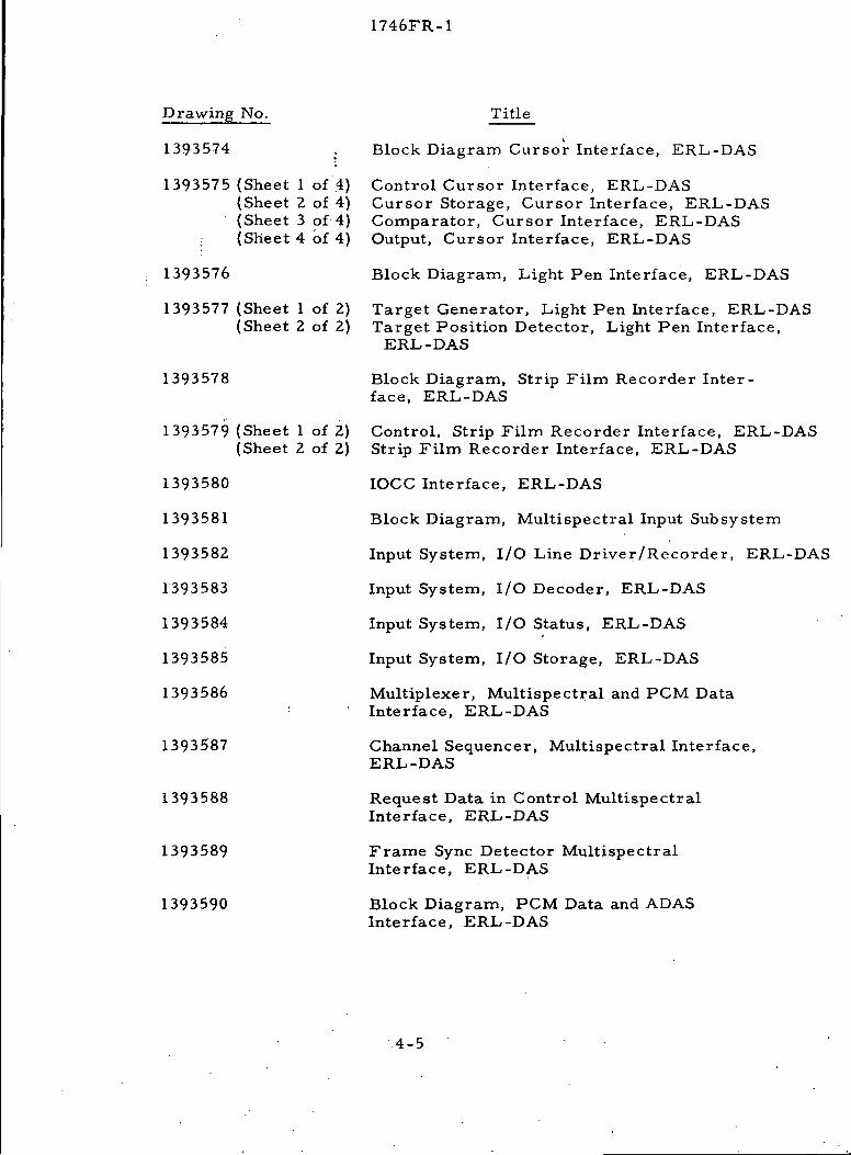
Drawing No.
1393574 ,
1393575 (Sheet 1 of 4){Sheet 2 of 4)(Sheet 3 of 4)(Sheet 4 of 4)
1393576
1393577 (Sheet 1 of 2)(Sheet 2 of 2)
1393578
1393579 (Sheet 1 of 2)(Sheet 2 of 2)
1393580
1393581
1393582
1393583
1393584
1393585
1393586
1393587
1393588
1393589
1393590
Title
t
Block Diagram Cursor Interface, ERL-DAS
Control Cursor Interface, ERL-DASCursor Storage, Cursor Interface, ERL-DASComparator, Cursor Interface, ERL-DASOutput, Cursor Interface, ERL-DAS
Block Diagram, Light Pen Interface, ERL-DAS
Target Generator, Light Pen Interface, ERL-DASTarget Position Detector, Light Pen Interface,
ERL-DAS
Block Diagram, Strip Film Recorder Inter-face, ERL-DAS
Control, Strip Film Recorder Interface, ERL-DASStrip Film Recorder Interface, ERL-DAS
IOCC Interface, ERL-DAS
Block Diagram, Multispectral Input Subsystem
Input System, I/O Line Driver/Recorder, ERL-DAS
Input System, I/O Decoder, ERL-DAS
Input System, I/O Status, ERL-DAS
Input System, I/O Storage, ERL-DAS
Multiplexer, Multispectral and PCM DataInterface, ERL-DAS
Channel Sequencer, Multispectral Interface,ERL-DAS
Request Data in Control MultispectralInterface, ERL-DAS
Frame Sync Detector MultispectralInterface, ERL-DAS
Block Diagram, PCM Data and ADASInterface, ERL-DAS
4-5

1746FR-1
Drawing No.
1393591
1393592
1393593
1393594
1393595
1393596
Title
Logic Diagram, PCM Data Interface, ERL-DAS
Logic Diagram, ADAS Interface, ERL-DAS
Analog Tape External Control, ERL-DAS
Block Diagram, Bench Test Unit, ERL-DAS
Bench Test Unit, ERL-DAS
Varian Equipment Connections, Rear View,ERL-DAS
4-6

1746FR-1
Section 5
ERL-DAS SPECIFICATION COMPLIANCE
The ERL-DAS system essentially meets all contractual specifications.
The Optical system illumination uniformity was specified to be . 5%0 It was
determined during the development of the optical system that this was beyond
the state-of-the-art for optical systems with the number of optical elements
contained in the ERL-DAS multispectral optical system.
Since the non-uniformity was inherent in the hardware, a special
software correction was added to the optical program enabling achievement of
a uniformity of approximately 2 percent. It was determined by NASA techni-
cal personnel that this illumination nonuniformity is more than adequate for
their applications.
Significant additional software and hardware capability has been
delivered in consideration for this specification deviation.
5-1
1746FR-1
Section 6
CONCLUSIONS AND RECOMMENDATIONS
6.1 CONCLUSIONS
The Earth Resources Laboratory Data Analysis System provides a
valuable research tool in the evaluation of Multispectral, S192, Photographic
and PMIS data. The system has been in operational use for approximately three
(3) months and has performed t[uite well.
Emphasis on versatility of both the hardware and software design
facilitates system expansion to many specialized data analysis tasks. The many
independent software handlers provide building blocks for major processing
programs.
6.2 RECOMMENDATIONS
Due to the complexity of the ERL-DAS it is recommended that a two
to three week hardware and software training program for NASA and NASA
support contractors be contracted with AESC. This training program will en-
able both software and hardware oriented personnel to better understand and
utilize the full ERL-DAS system capability.
6-1