case number - kentucky cases/99-343/99-343.pdf · within 5 day6 after construction reaches its ......
TRANSCRIPT

CASE NUMBER:
q7-343-

HISTORY INDEX FOR CASE: 1999-343 NPCR, INC. DBA NEXTEL PARTNERS
I
KY.
IN THE MATTER OF THE APPLICATION OF CROWN COMMUNICATION INC. AND NPCR, INC., C/B/A NEXTEL PARTNERS FOR ISSUANCE OF A CERTIFICATE OF PUBLIC CONVENIENCE AND NECESSITY TO CONSTRUCT A WIRELESS COMMUNICATIONS FACILITY AT 100 BUNKER HILL ROAD, WILLIAMSBURG, KY 40769 IN THE WIRELESS COMMUNICATIONS LICENSE AREA IN THE COMMONWEALTH OF KENTUCKY IN THE COUNTY OF WHITLEY SITE NAME: SAXTON
PUBLIC SERVICE COMMISSION AS OF : 03/06/00
PAGE 1
SEQ ENTRY NBR DATE REMARKS
0001 08/25/1999 Application.
0002 09/01/1999 Acknowledgement letter. 0003 09/08/1999 Def. letter, info due 9/23
MOO01 08/25/1999 DAVID PIKE CROWN COMMUNICATIONS-APPLICATION
MOO02 09/13/1999 DAVID PIKE CROWN COMMUNICATIONS-RESPONSE TO FILING DEFICIENCIES NOTICE 9-8-99 MOO03 09/23/1999 CROWN COMMUNICATIONS DAVID PIKE-MOTION TO SUBMIT 0004 10/01/1999 Def. cured letter 0005 11/01/1999 FINAL ORDER GRANTING CONSTRUCTION
MOO04 01/14/2000 DAVID PIKE CROWN COMMUNCATIONS-FEDERAL AVIATION & KY AIRPORT ZONING COMMISSION APPROVALS

0
Susan G. Hutcherson Filings Division Manager, Docket Branch Kentucky Public Service Commission 730 Schenkel Lane P.O. Box 615 Frankfort, KY 40602
January 13,2000
Re: Applicant: Crown Communication, Inc. PSC Case No.: 99-343 Crown Site No.: 304KY Crown Site Name: Saxton Federal Aviation Administration Approval Kentucky Airport Zoning Commission Approval
Dear Susan:
Please accept this letter and the attached documents as an official filing in the above- referenced Public Service Commission action. The Certificate of Public Convenience and Necessity issued in this action called for the Applicant to file a copy of the Federal Aviation Administration and Kentucky Airport Zoning Commission approvals once they were obtained. Copies of this relevant documentation are attached to this letter for inclusion in the official case file.
If you have any questions or comments concerning this matter, please do not hesitate to contact me.
Since re1 y ,
H d b David A. Pike Regional Counsel, Crown Communication Inc. E-mail: [email protected]
DAP/sl b
Enclosures
~
Shepherdsville Office 200 S. Buckman Street P.O. Box 369 Shepherdsville, Kentucky 40165-0369 (502) 955-4400 / Fax: (502) 543-4410
Frankfort Office Frankfort Plaza P.O. Box 771 Frankfort. Kentucky 40602-0771 (502) 875-4048
c , \
Federal Aviation Administration Southern Region, ASO-520
Atlanta, GA 30320 P.0. BOX 2 0 6 3 6
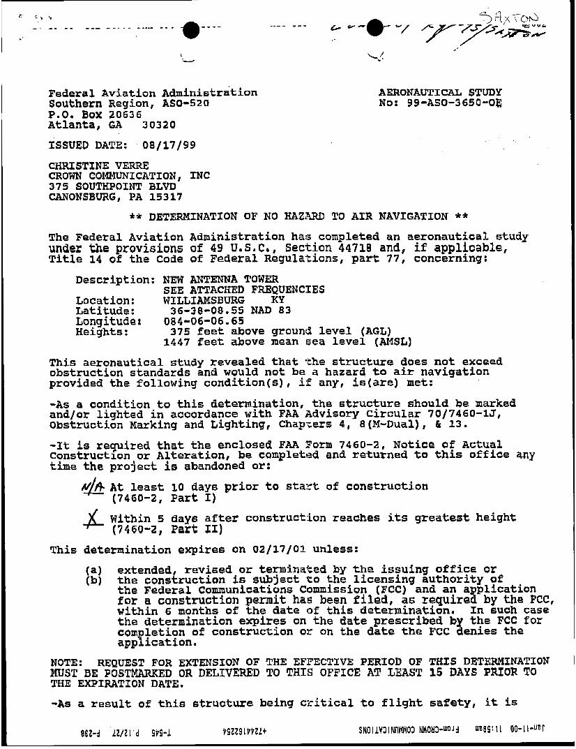
AEZ€ONAUTICAL STUDY Not 99-AS0-3650-0E
ISSUED DATE: 08/17/99
CHRISTINE VERRE CROWN COMMUNICATION, INC 375 SOUTHPOINT BLVD' CANONSBWRG, PA 15317
** DETERMINATION OF NO HAZARD TO AIR NAVIGATION ** 'She Federal Aviation Adninistration has completed an aeronautical study under the provisions of 49 U . S . C . , Section 44718 and, if applicable, T i t l e 14 of the Code of Federal Regulations, part 77, concerning:
Description: NEW ANTENNA TOWER
Location: WILLIAMSBURG KY SEE ATTACHED FREQUENCIES
Latitude: 36-38-08.55 NAD 83 Longitude: 084-06-06.65 Heights: 3 7 5 feet above ground level (AGL)
1 4 4 7 feet above mean 6ea level (AMSL)
This aeronautical study revealed that the structure doas not exceed obstruction standards and would not be a hazard to air navigation provided the following condition(s), if any, is(are) met: -As a condition to this determination, the structure should be marked and/or lighted in accordance w i t h FAA Advisory Circular 70/7460-1J, Obstruction Marking and Lighting, ChapTers 4, 8 (M-Dual) , h 13.
-It is required that the enclosed FAA ? o m 7460-2, Notice of Actual Construction or Alteration, be completed and returned to this office my t h e the project is abandoned or:
A$&- A t least 1 0 day6 prior t o StaYL of construction (7460-2, Part I) Within 5 day6 after construction reaches its greatest height (7460-2, Part ZI)
This determination expire6 on 02/17/02 unless: a) extended, revised or terminated by the issuing office or 'b) the construction Ls subject to the licensing authority of
the Federal Communications Commission (FCC) and an application f o r a construction permit has been filed, as required by t h e FCC, within 6 months of the date of this determination. I n such case the determination expires on the date prescribed by t h e FCC fo r completion of construction or on the date the FCC denies the application.
NOTE: MUST BE POSTMARKED OR DEZIVERED TO THIS OFFICE AT LUST 15 DAYS PRIOR TO THE EXPIRATION DATE.
-As a resul t of this structure being critical to flight safety, it fs
REQUEST FOR EXTENSION OF THE EFFECTIVE PERIOD OF THIS DETF,W1NATION
e--- A"'*-."" **.- *-..", *.- - - - i
_. . 0
required that t h e FAA be kept apprised as to the status of this I Failure to respond t o periodic FAA inquiries could invalidate
a=;:terrninati*n.
This determination is based, in part, on the foregoing description which includes specific coordinates, heights, fre ency(ie6) and power. Any
w i l l void this determination. including increase in heights, power, or the addition of other transmitters, requires separate notice to the FAA.
This determination does include temporary construction equipment such a6 cranes, derricks, etc., which may be used during actual construction of the structure. heights as indicated above. studied structure requires separate notice to the FAA.
This determination concerns the effect of this structure on the safe and efficient use of navigable airspace by aircraft and does not relieve #e sponsor of compliance responsibilities relating to any law, ordinance, or regulation of any Federal, State, or local government body.
A copy of this determination w i l l lje forwarded to t h e Federal Communications Comission if the structure is subject to their licensing authority. If we cannbe of further assistance, please contact our office a t 404-305+%?Y. please refer to Aeronautical Study Number 99-ASO-3650-OE.
changes in coordinates, heights, frequency( 9" es) or use of greater power Any future construction or alteration,
However, this equipment shall not exceed the overall Equipment which has a height greater than the
m1 On any future correspondence concerning this matter,
7460-2 Attached

s C L Y - t C w (502) ? G y p
fax (?02) ?G4-7953
KentucWy Airport honing Corn 125 Holmes Street
Frankfort, K Y 40622 Nn.: ~&l.1R-WWt-99-148
September 14,1999
APPROVAL OF APPLICATJON
APPLICANT: CROWN COMMUNICATlON INC CFIlUSmE VERRE. REGULATORY COORDINATOR 375 50UX P O N I X BOULEVARD Cwonsburg. P A 153 17
SUBJECT: AS-1 IS-WC-99-148
STRUCTURE: Antenna Tower LOCATION: williamsbur&, KY COORDMATES: 3678'08.55"N / S4°06'06:65"W HEIGHT: 375-AGLI1.447'AMSL
l i e Kentucky Airport Zoning Commission has approved your application for a permit to construcr (375'AGWl1447'AMSL) Antenna Tower near Williamsbwg, KY 36O38'09"N, 84*06'07"W,
This parniit is valid for a period of 18 Month(s) from its date of issuance. If comiruction is not completed lvithin said 16-Month period. this permit shall lapsr: and be void, and no work shall be performed without the issuance of a IICW permit.
A copy of thc approvcd application is enclosed for your files.
Dual obstruction lighting is required in accordanae with 602 KAR 50: 100..
Rohd Bland, Administrator

KY. PUBLIC SERVICE COMMISSION AS OF : 11/01/99 c INDEX FOR CASE: 99-343
NPCR, INC. DBA NEXTEL PARTNERS
CELL SITE - 100 BUNKER HILL ROAD - WILLIAMSBURG Construct
IN THE MATTER OF THE APPLICATION OF CROWN COMMUNICATION INC. AND NPCR, INC., C/B/A NEXTEL PARTNERS FOR ISSUANCE OF A CERTIFICATE OF PUBLIC CONVENIENCE AND NECESSITY TO CONSTRUCT A WIRELESS COMMUNICATIONS FACILITY AT 100 BUNKER HILL ROAD, WILLIAMSBURG, KY 40769 IN THE WIRELESS COMMUNICATIONS LICENSE AREA IN THE COMMONWEALTH OF KENTUCKY IN THE COUNTY OF WHITLEY SITE NAME: SAXTON
SEQ ENTRY NBR DATE REMARKS
0001 MOO01 0002 0003
MOO02 MOO03 0004 0005
oa/25/99 08/25/99 09/01/99 og/oa/gg
10/01/99 11/01/99
09/13/99 09/23/99
Application.
Acknowledgement letter. Def. letter, info due 9/23
DAVID PIKE CROWN COMMUNICATIONS-APPLICATION
DAVID PIKE CROWN COMMUNICATIONS-RESPONSE TO FILING DEFICIENCIES NOTICE 9 CROWN COMMUNICATIONS DAVID PIKE-MOTION TO SUBMIT
FINAL ORDER GRANTING CONSTRUCTION Def. cured letter
PAGE 1
%PSM-E-OPENIN, error opening -PSCVXA$DUC3: [ALDRIDGEIHRNG-1NDEX.PRT;l as input -RMS-E-FNF, file not found

COMMONWEALTH OF KENTUCKY PUBLIC SERVICE COMMISSION
730 SCHENKEL LANE POST OFFICE BOX 61 5
FRANKFORT, KY. 40602 (502) 564-3940
CERTIFICATE OF SERVICE
RE: Case No. 99-343 NPCR, INC. DBA NEXTEL PARTNERS
I, Stephanie Bell, Secretary of the Public Service Commission, hereby certify that the enclosed attested copy of the Commission’s Order in the above case was served upon the following by U.S. Mail on November 1, 1999.
See attached parties of record.
Secretary of the Commission
SB/sa Enclosure

Donald J. Manning Vice President and General Counsel NPCR, Inc. dba Nextel Partners
I 4500 Carillon Point Kirkland, WA. 98033
Rodney Strong Crown Communications Inc. 11001 Bluegrass Parkway, Suite 330 Louisville. KY. 40299
Honorable David A. Pike Counsel for Crown Communication Pike Legal Group 200 S. Buckman Street P. 0. Box 369 Shepherdsville , KY. 40165 0369
Honorable W. Brent Rice Counsel for Nextel Partners McBrayer, McGinnis, Leslie & Kirkland 163 W. Short Street Lexington, KY. 40507 1361

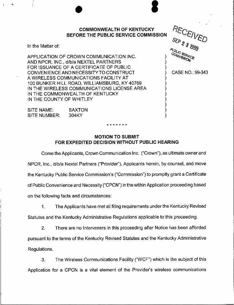
COMMONWEALTH OF KENTUCKY
BEFORE THE PUBLIC SERVICE COMMISSION
In the Matter of:
APPLICATION OF CROWN COMMUNICATION INC. AND NPCR, INC. D/B/A NEXTEL PARTNERS FOR ISSUANCE OF A CERTIFICATE OF PUBLIC CONVENIENCE AND NECESSITY TO CONSTRUCT A WIRELESS COMMUNICATIONS FACILITY AT 100 BUNKER HILL ROAD, WILLIAMSBURG, KY 40769 IN THE WIRELESS COMMUNICATIONS LICENSE AREA IN THE COMMONWEALTH OF KENTUCKY IN THE COUNTY OF WHITLEY SITE NAME: SAXTON SITE NUMBER: 304KY
O R D E R
On August 25, 1999, Crown Communication Inc. ("Crown") and NPCR, Inc. d/b/a
Nehel Partners (collectively, the "Applicants") filed an application seeking a Certificate of
Public Convenience and Necessity to construct and operate a wireless telecommunications
facility. The proposed facility consists of a guyed antenna tower not to exceed 375 feet in
height, with attached antennas, to be located at I00 Bunker Hill Road, Williamsburg,
Whitley County, Kentucky. The coordinates for the proposed facility are North Latitude 36"
38' 8.55" by West Longitude 84" 6' 6.65".
Crown has provided information regarding the structure of the tower, safety
measures, and antenna design criteria for the proposed facility. Based upon the
application, the design of the tower and foundation conforms to applicable nationally

recognized building standards, and the plans have been certified by a Registered
Professional Engineer.
Pursuant to 807 KAR 5063, the Applicants have notified the County
Judge/Executive of the proposed construction. To date, no comments have been filed.
The Applicants have filed applications with the Federal Aviation Administration (''FM") and
the Kentucky Airport Zoning Commission ("KAZC") seeking approval for the construction
l and operation of the proposed facility. Both applications are pending.
I
i The Applicants have filed evidence of the appropriate notices provided pursuant to
807 KAR 5063. The notices solicited any comments and informed the recipients of their
right to request intervention. To date, no comments have been filed with the Commission.
Pursuant to KRS 278.280, the Commission is required to determine proper
practices to be observed when it finds, upon complaint or on its own motion, that the
facilities of any utility subject to its jurisdiction are unreasonable, unsafe, improper, or
insufficient. To assist the Commission in its efforts to comply with this mandate, Crown
should notify the Commission if it does not use this antenna tower to provide service in the
manner set out in its application and this Order. Upon receipt of such notice, the
Commission may, on its own motion, institute proceedings to consider the proper practices,
including removal of the unused antenna tower, which should be observed by Crown.
~
The Commission, having considered the evidence of record and being otherwise
sufficiently advised, finds that the Applicants have demonstrated that a facility is necessary
to provide adequate utility service and therefore should be granted a Certificate of Public
Convenience and Necessity to construct the proposed facility.
-2-
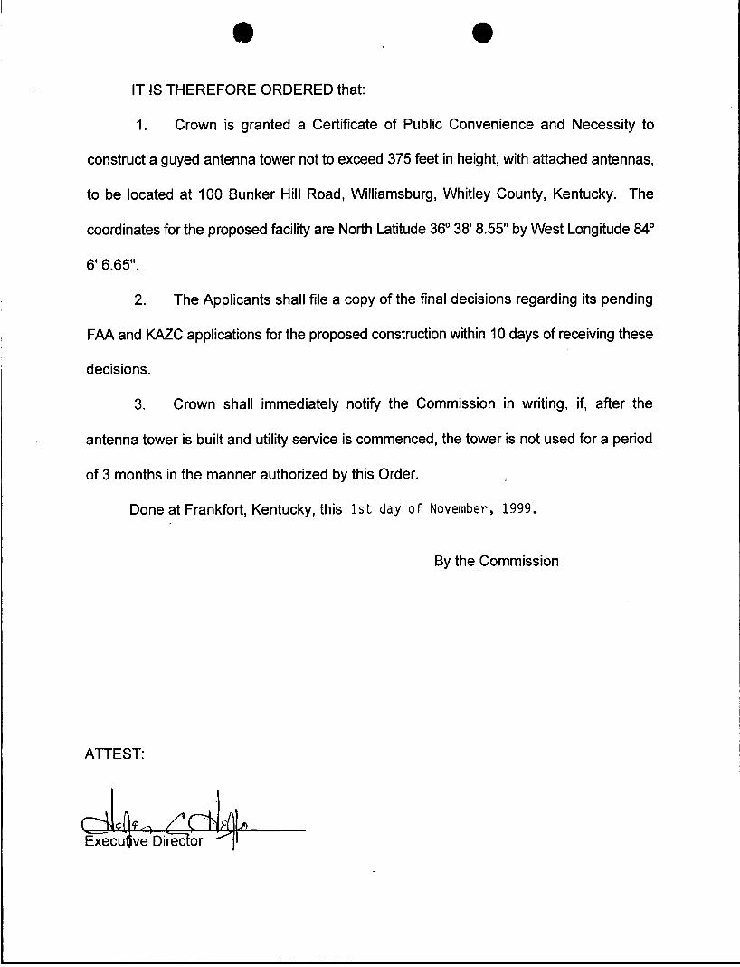
IT IS THEREFORE ORDERED that:
1. I
Crown is granted a Certificate of Public Convenience and Necessity to
construct a guyed antenna tower not to exceed 375 feet in height, with attached antennas,
to be located at I00 Bunker Hill Road, Williamsburg, Whitley County, Kentucky. The I I coordinates for the proposed facility are North Latitude 36" 38' 8.55" by West Longitude 84'
6' 6.65".
2. The Applicants shall file a copy of the final decisions regarding its pending
FAA and KAZC applications for the proposed construction within 10 days of receiving these
decisions.
3. Crown shall immediately notify the Commission in writing, if, after the
antenna tower is built and utility service is commenced, the tower is not used for a period
of 3 months in the manner authorized by this Order. i'
Done at Frankfort, Kentucky, this 1 s t day o f November, 1999.
By the Commission
ATTEST:

C O M M O N W E A L T H O F KENTUCKY PUBLIC SERVICE COMMISSION
730 SCHENKEL LANE POST OFFICE BOX 61 5
FRANKFORT, KY. 40602 (502) 564-3940
October 1, 1999
To: All parties of record
RE: Case No. 99-343 NPCR, INC. DBA NEXTEL PARTNERS
The Commission staff has reviewed your response of September 13, 1999 and has determined that your application in the above case now meets the minimum filing requirements set by our regula- tions. Enclosed please find a stamped filed copy of the first page of your filing. processed as expeditiously as possible.
at 502/564-3940.
This case has been docketed and will be
If you need further information, please contact my staff
Sincerely,
Stephanie Bell Secretary of the Commission
SB/sa Enclosure

Donald J. Manning Vice President and General Counsel NPCR, Inc. dba Nextel Partners 4500 Carillon Point Kirkland, WA. 98033
Rodney Strong Crown Communications Inc. 11001 Bluegrass Parkway, Suite 330 Louisville, KY. 40299
Honorable David A. Pike Counsel for Crown Communication Pike Legal Group 200 S . Buckman Street P. 0. Box 369 Shepherdsville , KY. 40165 0369
Honorable W. Brent Rice Counsel for Nextel Partners McBrayer, McGinnis, Leslie & Kirkland 163 W. Short Street Lexington, KY. 40507 1361

August 24, 1999
VIA HAND DELIVERY
Helen C. Helton Executive Director Kentucky Public Service Commission 730 Schenkel Lane P. 0. Box615 Frankfort, Kentucky 40602
RECEiVED AUG 2 5'1999
SEP 1 3 1999
Re: Request for Waiver for From Requirements for Duplicate Initial Filing PSC Case Number: 99-343 Site Name: Saxton Site Number: 304KY
Dear Helen:
Please accept this letter as our formal application for waiver of the requirement that an original and ten ( I O ) copies of an initial application for issuance of Certificate of Public Convenience and Necessity be filed with the Kentucky Public Service Commission ("PSC") in wireless communications facilities cases. As is the normal custom, we request that we be allowed to file an original and five (5) copies of our application for Certificate of Public Convenience and Necessity.
Thank you for your courtesy. If you have any questions or comments concerning this matter, please do not hesitate to contact me.
Sincerely,
Regional Counsel for Crown Communication Inc.
DAP: stb
For Inclusion in Application File - Shepherclsville 0tXic.e 200 S. Buckm:in Srrrrt P.0. Box 369 Shrpherdsville. Kentucky 40165-0369 (502) 9554400 / Fix: (502) 543-4410
Frinkfon Office Frankfon PlazJ P.O. Box 771 Frankfort. Kentucky iO602-0771 (502) 875-4048

Paul E. Patton Governor
COMMONWEALTH OF KENTUCKY PUBLIC SERVICE COMMISSION
730 SCHENKEL LANE POST OFFICE BOX 61 5
www.psc.state.ky.us Helen Helton
Ronald B. McCloud, Secretary Public Protection and
Regulation Cabinet
(502) 564-3940 Executive Director
FRANKFORT, KENTUCKY 40602
Fax (502) 564-3460 Public Service Commission
September 8, 1999
Donald J. Manning Vice President and General Counsel NPCR, Inc. 4500 Carillon Point Kirkland, WA 98033
Honorable W. Brent Rice McB raye r, McGi n n is, Leslie & Kirkland 163 W. Short Street Lexington, KY 40507 1361
Re: Case No. 99-343 Filing Deficiencies
Gentlemen:
The Commission staff has conducted an initial review of your filing in the above case. This filing is rejected pursuant to 807 KAR 5:001, Section 2, as it is deficient in certain filing requirements. The items listed below are either required to be filed with the application or must be referenced if they are already on file in another case or will be filed at a later date.
Filing deficiencies pursuant to 807 KAR 5:063, Section l(l)(d):
A geotechnical investigation report, signed and sealed by a professional engineer registered in Kentucky, that includes boring logs, foundation design recommendations, and a finding as to the proximity of the proposed site to flood hazard areas (findings re: flood hazard area proximity may be prepared by a land surveyor).
AN EQUAL OPPORTUNITY EMPLOYER M/FD

e m' Page Two Filing Deficiencies
The statutory time period in which the Commission must process this case will not commence until the above-mentioned information is filed with the Commission. You are requested to file 10 copies of this information within 15 days of the date of this letter. If you need further information, please contact James Jenkins of my staff at (502) 564- 3940, ext. 409.
Sincerelv,
Stephanie Bell Secretary of the Commission
sa
cc: Parties of Record
AN EQUAL OPPORTUNITY EMPLOYER IwF/D
I
0
COMMONWEALTH OF KENTUCKY BEFORE THE PUBLIC SERVICE COMMISSION
In the Matter of:
APPLICATION OF CROWN COMMUNICATION INC. AND NPCR, INC., d/b/a NEXTEL PARTNERS FOR ISSUANCE OF A CERTIFICATE OF PUBLIC CONVENIENCE AND NECESSITY TO CONSTRUCT ) CASE NO.: 99-343 A WIRELESS COMMUNICATIONS FACILITY AT 100 BUNKER HILL ROAD, WILLIAMSBURG, KY 40769 IN THE WIRELESS COMMUNICATIONS LICENSE AREA IN THE COMMONWEALTH OF KENTUCKY IN THE COUNTY OF WHITLEY
1
1 ) ) ) ) )
SITE NAME: SAXTON 1 SITE NUMBER: 304KY 1
* * * * * * *
MOTION TO SUBMIT FOR EXPEDITED DECISION WITHOUT PUBLIC HEARING
Come the Applicants, Crown Communication Inc. (“Crown”), as ultimate owner and
NPCR, Inc., d/b/a Nextel Partners (“Provider”), Applicants herein, by counsel, and move
the Kentucky Public Service Commission’s (“Commission”) to promptly grant a Certificate
of Public Convenience and Necessity (“CPCN”) in the within Application proceeding based
on the following facts and circumstances:
1. The Applicants have met all filing requirements under the Kentucky Revised
Statutes and the Kentucky Administrative Regulations applicable to this proceeding.
2. There are no Interveners in this proceeding after Notice has been afforded
pursuant to the terms of the Kentucky Revised Statutes and the Kentucky Administrative
Regulations.
3. The Wireless Communications Facility (“WCF”) which is the subject of this
Application for a CPCN is a vital element of the Provider’s wireless communications

network, and is necessary to provide service in accordance with provisions of its license
with the Federal Communications Commission.
4. The county where the WCF is located has not registered for the right to
regulate cell cites with the PSC, and has not adopted planning and zoning regulations in
accordance with KRS 100.
5. The Application in this administrative proceeding was originally filed with the
Commission on August 25, 1999, 29 days before the submission of this Motion.
WHEREFORE, Crown Communication Inc. and NPCR, Inc., d/b/a Nextel Partners
("Provider"), Applicants herein, by counsel, urge the Kentucky Public Service Commission
to promptly grant a Certificate of Public Convenience and Necessity in accordance with the
terms of the Application in this proceeding without public hearing.
Respectfully submitted, P
Pike Legal Group 200 S. Buckman Street Post Office Box 369 Shepherdsville, KY 401 65-0369 Telephone: (502) 955-4400
E-Mail: ATTORNEY FOR CROWN COMMUNICATION INC.
Telefax: (502) 543-441 0 pi keleg al @aol . com
and
W. Brent Rice McBrayer, McGinnis, Leslie & Kirkland 163 W. Short Street Lexington, KY 40507-1361 Telephone: (606) 231-8780 COUNSEL FOR NCPR, INC., d/b/a NEXTEL PAR 'NERS

1. . , i e COMMONWEALTH OF KENTUCKY
BEFORE THE PUBLIC SERVICE COMMISSION
In the Matter of:
APPLICATION OF CROWN COMMUNICATION INC. AND NPCR, INC., d/b/a NEXTEL PARTNERS FOR ISSUANCE OF A CERTIFICATE OF PUBLIC CONVENIENCE AND NECESSITY TO CONSTRUCT A WIRELESS COMMUNICATIONS FACILITY AT 100 BUNKER HILL ROAD, WILLIAMSBURG, KY 40769 IN THE WIRELESS COMMUNICATIONS LICENSE AREA IN THE COMMONWEALTH OF KENTUCKY IN THE COUNTY OF WHITLEY
SITE NAME: SAXTON SITE NUMBER: 304KY
* * * * * * *
RESPONSE TO FILING DEFICIENCIES NOTICE - 9/8/99
Comes Crown Communication Inc. (“Crown”), as ultimate owner and NPCR, Inc.,
d/b/a Nextel Partners (“Provider”), Applicants, by counsel, and for their Response to the
Kentucky Public Service Commission’s (“Commission”) Filing Deficiencies Notice dated
September 8, 1999, state as follows:
1. The Filings Deficiencies Notice dated September 8, 1999 (“Deficiencies
Notice”) lists a failure pursuant in 807 KAR 5:063, Section l( l)(d) in that the Applicants I failed to submit a geotechnical investigation report sianed and sealed by a professional
engineer registered in Kentucky. The geotechnical investigation submitted by the
Applicants as Exhibit H to their original Application received by the Commission on
September 1, 1999 was not signed and sealed by a professional engineer.
2. Attached to this Response is a new Exhibit H to be appended to the original
Application received by the Commission in this administration action on September 1,1999

replacing the previous Exhibit H. This new geotechnical investigation report is properly
signed and sealed by a professional engineer registered in Kentucky.
3. A Flood Hazard Proximity Statement in compliance with the terms of 807
KAR 5:063, Section l( l)(d) is included as part of the Applicants’ original Exhibit B, Page
C-2 attached to their Application filed in this administrative action on September 1, 1999.
WHEREFORE, the Applicants submit their Response to the Deficiencies Notice,
and request that the Commission take all necessary steps to promptly enter their original
Application as having been filed effective September 1 , 1999, the original date of receipt
of the Application by the Commission.
Respectfully submitted,
Pike Legal Group 200 S. Buckman Street Post Office Box 369 Shepherdsville, KY 401 65-0369 Telephone: (502) 955-4400
E-Mail: ATTORNEY FOR CROWN COMMUNICATION INC.
Telefax: (502) 543-44 1 0 pi keleg al @ aol . com
and
W. Brent Rice McBrayer, McGinnis, Leslie & Kirkland 163 W. Short Street Lexington, KY 40507-1 361 Telephone: (606) 231-8780 COUNSEL FOR NCPR, INC., d/b/a NEXTEL PARTNERS

COMMONWEALTH OF KENTUCKY PUBLIC SERVICE COMMISSION
730 SCHENKEL LANE POST OFFICE BOX 61 5 FRANKFORT, KY. 40602
(502) 564-3940
September 1, 1999
To: All parties of record
RE: Case No. 99-343 NPCR, INC. DBA NEXTEL PARTNERS (Construct) CELL SITE - 100 BUNKER HILL ROAD - WILLIAMSBURG
This letter is to acknowledge receipt of initial application in the above case. The application was date-stamped received August 25, 1999 and has been assigned Case No. 99-343. In all future correspondence or filings in connection with this case, please reference the above case number.
If you need further assistance, please contact my staff at 502/564-3940.
Sincerelv.
Stephanie Bell Secretary of the Commission

Donald J. Manning vice President and General Counsel NPCR, Inc. &a Nextel Partners 4500 Carillon Point Kirkland. WA. 98033
1
Rodney Strong Crown Communications Inc. 11001 Bluegrass Parkway, Suite 330 Louisville, KY. 40299
Honorable David A. Pike Counsel for Crown Communication Pike Legal Group 200 S. Buckman Street P. 0. Box 369 Shepherdsville , KY. 40165 0369
Honorable W . Brent Rice Counsel for Nextel Partners McBrayer, McGinnis. Leslie & Kirkland 163 W. Short Street Lexington, KY. 40507 1361
AUG 2 5 ‘I999
August 24, 1999
VIA HAND DELIVERY
Helen C. Helton Executive Director Kentucky Public Service Commission 730 Schenkel Lane P. 0. Box 615 Frankfort, Kentucky 40602
SEP : 3 1999 ptJBL\C SERVICE comrssr0N
Re: Request for Waiver for From Requirements for Duplicate Initial Filing .- - PSC Case Number: 99-343
Site Name: Saxton Site Number: 304KY
Dear Helen:
Please accept this letter as our formal application for waiver of the requirement that an original and ten (IO) copies of an initial application for issuance of Certificate of Public Convenience and Necessity be filed with the Kentucky Public Service Commission (“PSC”) in wireless communications facilities cases. As is the normal custom, we request that we be allowed to file an original and five (5) copies of our application for Certificate of Public Convenience and Necessity.
Thank you for your courtesy. If you have any questions or comments concerning this matter, please do not hesitate to contact me.
Sincerely,
Regional Counsel for Crown Communication Inc.
DAP:slb
For Inclusion in Application File
7 Shepherclsville Office 200 S Buckmdn Street P 0 Box 369 Shepherdsville, Kentucky 40165-0369 (502) 955-4400 / Fax (502) 543-4410
Frdnkfort Office Frankfort Plaza P 0 Box 771 Frankfort, Kentucky 40602-0771 (502) 875-4048

In the Matter of:
APPLICATION OF CROWN COMMUNICATION INC. AND NPCR, INC., d/b/a NEXTEL PARTNERS FOR ISSUANCE OF A CERTIFICATE OF PUBLIC CONVENIENCE AND NECESSITY TO CONSTRUCT) A WIRELESS COMMUNICATIONS FACILITY AT 100 Bunker Hill Road, Williamsburg, KY 40769 IN THE WIRELESS COMMUNICATIONS LICENSE AREA IN THE COMMONWEALTH OF KENTUCKY IN THE COUNTY OF Whitley
1 ) )
) 1
1 1
, CASE NO.: 99-343
)
SITE NAME: Saxton SITE NUMBER: 304KY
* * * * * * *
Crown Communication Inc. (“Crown”), as ultimate owner, and NPCR, INC., d/b/a
NEXTEL PARTNERS (“Provider”), as a licensed public utility in the Commonwealth of
Kentucky, hereinafter jointly referred to as “Applicants”, by counsel, pursuant to (i) KRS
278.020 and the rules. and regulations applicable thereto, and (ii) the Telecommunications
Act of 1996, respectfully submit their Application for a Certificate of Public Convenience
and Necessity (‘CPCN”) from the Public Service Commission of Kentucky (“Commission”)
to construct, maintain, and operate a Wireless Communications Facility (“WCF”) to serve
the customers of the Provider with wireless telecommunications services, and other
wireless service provider collocations in the area described herein.
In support of this Application, the Applicants respectfully provide and state the
following information:
2

1. The complete names and addresses of the Applicants are:
Crown Communication Inc., a Delaware Corporation, 375 Southpointe Boulevard, Canonsburg, PA 1531 7, (724) 416-2000, having a local address of Commonwealth Business Center, 1 1001 Bluegrass Parkway, Suite 330, Louisville, Kentucky 40299, (502) 240-0044.
NPCR, INC., d/b/a Nextel Partners, 9 East Loockerman Street, Dover, Delaware 19901.
2. Crown constructs, owns, manages, maintains, and operates independent
communications networks. Crown owns and manages safe, clean, and well-maintained
facilities. Crown facilities do not generate smoke, odors, noise, noxious gases, vibrations,
or increase traffic. Studies show that Crown’s facilities will not pollute air, soil, or water, nor
will they adversely affect radio or television reception or transmission. A certified copy of
the Certificate of Authority under the name of Crown Communication Inc., issued by the
Secretary of State of the Commonwealth of Kentucky, and a certified copy of the Articles
of Incorporation issued by the Secretary of State of Delaware are attached hereto as
Exhibit A. A certified copy of the Certificate of Authority under the name of NPCR, INC.,
issued by the Secretary of State of the Commonwealth of Kentucky, and a certified copy
of the Articles of Incorporation issued by the Secretary of State of Delaware are attached
hereto as Exhibit A.
3

3. After completion of the proposed WCF, Crown will lease or license space on
said tower and the surrounding site so that the Provider may locate and operate its facility
including all required antennas and appurtenances. The proposed WCF will serve an area
completely within the Provider’s FCC licensed service area in the Commonwealth of
Kentucky. The Provider is authorized to provide wireless services by the FCC and the
Commission. Crown has located the proposed site in a manner such that other wireless
communications service providers will desire to collocate on said tower, and will endeavor
to provide all necessary facilities to make collocation attractive to them.
4. The public convenience and necessity require the construction of the
proposed WCF. The construction of the WCF will bring the Provider’s services to an area
currently not served by the Provider and will thereby enhance the public’s access to
innovative and competitive wireless telecommunications services. The WCF will provide
a necessary link in the Provider’s telecommunications network that is designed to meet the
increasing demands for wireless services in Kentucky’s wireless communications licensed
area. The WCF is an integral link in the Provider’s network design that must be in place
to cover the proposed service area.
5. Crown’s construction of the described WCF is desirable because it allows for
the collocation of additional wireless service providers within this portion of the Kentucky
wireless communications licensed area. These services may include telecommunications,
wireless data transfer and Internet services, wireless cable, paging systems, 91 1 service,
and other new products currently being developed in the wireless industry. In addition, the
4

WCF will be available for use by governmental agencies and providers of emergency
services. The WCF will provide a necessary link in Crown’s wireless infrastructure
network, and Crown, as part of its business structure, will diligently pursue and encourage
other wireless providers to collocate on the WCF. These services will provide increased
competition in the local Kentucky telecommunications market, which will, in turn, promote
competitive pricing, quality, and coverage options to users of telecommunications services
in this area. Crown’s vested interest in the collocation of wireless service providers
promotes the same goals for the local consumers.
6. The Applicants propose to construct a WCF at 100 Bunker Hill Road,
Williamsburg, KY 40769, (36” 38’ 08.55” North latitude, 84” 06’ 06.65” West longitude), in
an area located entirely within the county referenced in the caption of this application. The
property on which the WCF will be located is owned by Kenneth and Linda Anderson. The
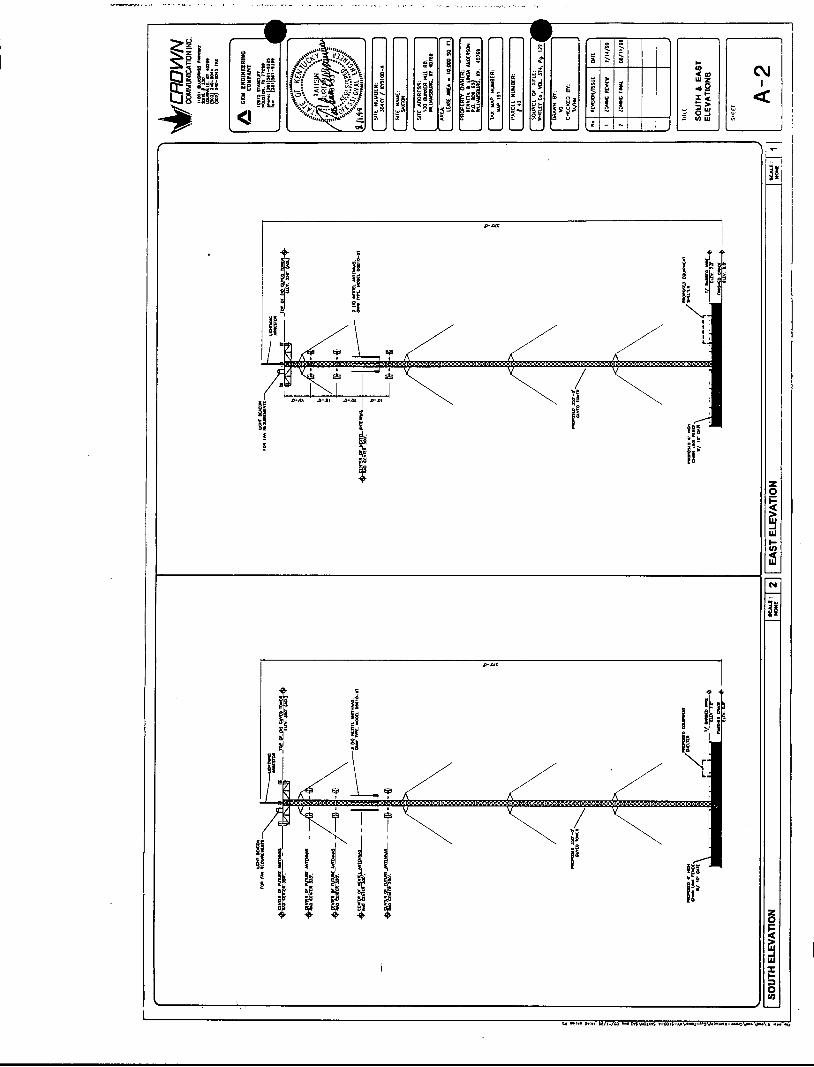
proposed WCF will consist of a 350-foot guyed tower, with an approximately 25-foot
lightning arrestor attached at the top, for a total height of 375 feet. The WCF will also
include concrete foundations to accommodate the placement of the Provider’s proprietary
radio electronics equipment. The equipment will be housed in a prefabricated cabinet or
shelter that will contain: (i) the transmitting and receiving equipment required to connect
the WCF with the Provider’s users in Kentucky, (ii) telephone lines that will link the WCF
with the Provider’s other facilities, (iii) battery back-up that will allow the Provider to operate
even after a loss of outside power, and (iv) all other necessary appurtenances. The
Provider’s equipment cabinet or shelter will be approved for use in the Commonwealth of
Kentucky by the relevant building inspector. The WCF compound will be fenced and all
5

access gate(s) will be secured. A description of the manner in which the proposed WCF
will be constructed is attached as Exhibit B and C. Periodic inspections will be performed
on the WCF in accordance with the applicable regulations or requirements of the
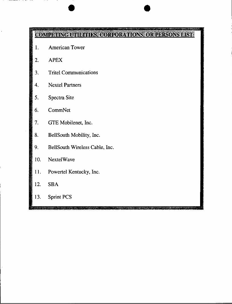
Commission. The list of competing utilities, corporations, or persons is attached as Exhibit
D.
7. Three (3) original site development plans have been submitted with this
Application; and reduced copies of this site development plan have been included as
Exhibit B and Exhibit C. A vertical profile sketch of the WCF signed and sealed by a
professional engineer registered in Kentucky depicting the tower height, as well as a
proposed configuration for the antennas of the Provider and future antenna mounts, has
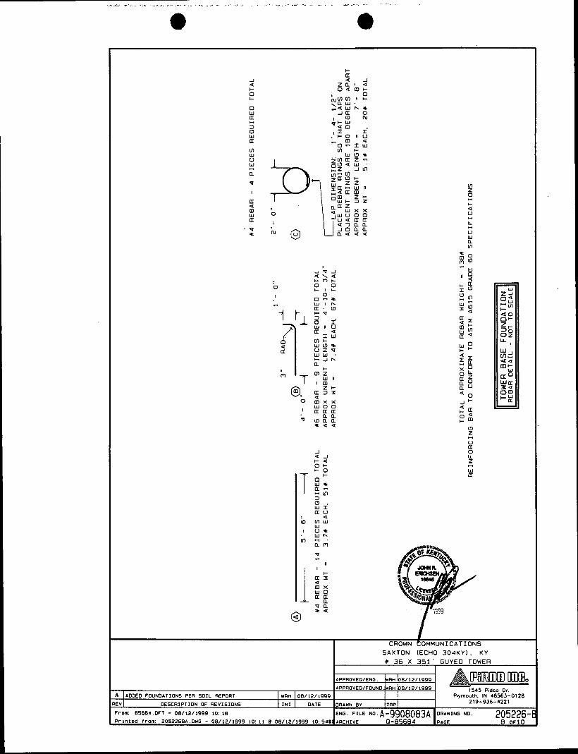
also been included as part of Exhibit B. Foundation design plans and a description of the
standards according to which the tower was designed signed and sealed by a professional
engineer registered in Kentucky is included as part of Exhibit C.
8. The Applicants have considered the likely effects of the installation on nearby
land uses and values and have concluded that there is no more suitable location
reasonably available from which adequate services can be provided, and that there are no
reasonably available opportunities to collocate. The Applicants have attempted to
collocate on suitable existing structures such as a telecommunications towers or other
suitable structures capable of supporting the Provider’s facilities. No other suitable and
available collocation site was found to be located in the vicinity of the site. Information
regarding the Applicants’ efforts to achieve collocation in the vicinity are presented as
Exhibit E.
6
9. The Applicants have conducted a preliminary aeronautical evaluation for the
proposed WCF. The evaluation determined that the proposed structure height at this site
meets Federal Aviation Regulation requirements. Furthermore, FAA notice is required for
the proposed construction, and lighting or marking requirements may be applicable to this
facility. A copy of the FAA Application is attached as Exhibit F. Upon receiving
authorization from the FAA, the Applicants will foward a copy of the determination as a
supplement to this Application proceeding.
IO. A copy of the Kentucky Airport Zoning Commission (“KAZC”) Application for
the proposed WCF is attached as Exhibit G. Upon receiving authorization from the KAZC,
the Applicants will fomvard a copy of the determination as a supplement to this Application
proceeding.
11. The WCF will be registered with the Federal Communication Commission
(FCC) pursuant to applicable requirements for the structure and the provider. Appropriate
FCC signage will be posted at the site upon receipt of the tower registration number.
12. A geotechnical-engineering firm has performed soil boring(s) and subsequent
geotechnical-engineering studies at the WCF site under the supervision of a professional
engineer registered in the Commonwealth of Kentucky who specializes in geotechnical
engineering, including subsurface exploration. The geotechnical-engineering firm has
performed many such studies for the communications industry. A copy of the
geotechnical-engineering report and evaluation signed and sealed by a professional
engineer registered in the Commonwealth of Kentucky who specializes in geotechnical
engineering, including subsurface exploration, is attached as Exhibit H. The name and
7

address of the geotechnical-engineering firm and the professional engineer registered in
the Commonwealth of Kentucky who supervised the examination of this WCF site are
included in Exhibit H.
13. Clear directions to the proposed WCF site from the County seat are attached
as Exhibit 1. The name and address of the preparer of Exhibit I is included in Exhibit 1.
Crown, pursuant to a written agreement, has acquired the right to use the
WCF site and associated property rights. A copy of the abbreviated agreement recorded
with the County Clerk is attached as Exhibit J. Also included as part of Exhibit J is the
portion of the full agreement demonstrating that in the case of abandonment a method is
provided to dismantle and remove the cellular antenna tower, including a timetable for
removal.
14.
15. Personnel directly responsible for the design and construction of the
proposed WCF are well-qualified and experienced. Pirod Inc., (“the Tower Manufacturer”)
performed the t0we.r and foundation design. The Tower Manufacturer is a nationally
recognized manufacturer and designer of communications towers. The Tower
I Manufacturer has designed and installed communications towers throughout North
America. The Tower Manufacturer has assigned John R. Erichsen, a professional
engineer registered in the Commonwealth of Kentucky to design the WCF. This engineer
specializes in the design and engineering of guyed , self-support and monopole structures,
and has extensive experience in the design and construction of projects similar to the
Applicants’. These projects include the design of towers and the required foundations of
many other wireless facilities. All of the designs have been signed and sealed by John R.
a

Erichsen. The construction of the proposed WCF will be performed by Crown Network
Systems, an experienced, bonded, and insured erection company. The Tower Erection
Manager, Harold Harrington, will manage the tower erection. Harold Harrington is a tower
installation manager for Crown and has been erecting towers for the telecommunications
industry for over 8 years. All tower designs will meet or exceed applicable laws and
regulations.
16. Based on a review of Federal Emergency Management Agency Flood
Insurance Rate Maps, the registered land surveyor has noted in Exhibit B that the
proposed WCF is not located within any flood hazard area.
17. The possibility of high winds has been considered in the design of this tower.
The tower has been designed and engineered by professional engineers using computer
assistance and the same accepted codes and standards as are typically used for high-rise
building construction. The tower has been designed to withstand a wind loading of 70
m.p.h., using the Uniform Building Code of 1991 (“UBC-91”) and further modified by the
1993 Administrative Code. This tower has been designed in accordance with the
Electronic Industries Association (“EIA”) 222-F Standards, which have been accepted and
approved by ANSI and is a nationally recognized tower design standard. Similarly, the
proposed WCF design has been developed with consideration of potential ground shaking
based on a negligible seismic zone of 1. Seismic loading is regarded as secondary to the
wind loading.
18. The site development plan signed and sealed by a professional engineer
registered in Kentucky was prepared by Tashin Gurpinar and was designed from a survey
9
performed by Frank L. Sellinger. This site development plan is drawn to a scale of no less
than one (1) inch equals 200 feet, and identifies every owner of real estate within 500 feet
of the proposed tower (according to the Property Valuation Administrator) and is
incorporated in the survey as part of Exhibit B. Every structure and every easement within
500 feet of the proposed tower or within 200 feet of the access road including intersection
with the public street system is incorporated in the survey as part of Exhibit B.
19. Crown, on behalf of itself and the Provider, has notified every person who
owns property within 500 feet of the proposed tower by certified mail, return receipt
requested, of the proposed construction, along with the possibility of a temporary site being
built while awaiting Commission approval. Each property owner has been given the docket
number under which the proposed Application will be processed and has been informed
of their right to request intervention. A list of the nearby property owners who received the
notices, together with copies of the certified letters, are attached as Exhibits K and L,
respectively.
20. Crown, on behalf of itself and the Provider, has notified the Judge Executive
of the county where the WCF is located by certified mail, return receipt requested, of the
proposed construction. Crown included in said notice the Public Service Commission
docket number under which the application will be processed and informed said entity of
its right to request intervention. A copy of this notice is attached as Exhibit M. The county
where the WCF is located has not registered for the right to regulate cell sites with the
PSC, and has not adopted planning and zoning regulations in accordance with KRS
Chapter 100.
10

21. Two appropriate notice signs measuring at least two (2) feet in height and
four (4) feet in width with all required language in letters of required height have been
posted in a visible location on the proposed site and on the nearest public road and shall
remain posted for at least two (2) weeks after filing of the Application. Copies of the
postings are attached as Exhibit N. The location of the proposed facility has been
published in a newspaper of general circulation in the county where the WCF is located.
There is one residence within a 500-foot radius of the centerline of the
proposed tower location. The land surrounding the WCF site is presently vacant with the
balance of the remaining land consisting of raw acreage.
22.
23. The process that was used in selecting the site for the proposed WCF by the
Applicants’ radio frequency engineers was consistent with the process used for selecting
generally all other existing and proposed WCF facilities within the proposed network design
area. Before beginning the acquisition process, the Applicants carefully evaluated the
location of the required WCF for possible collocation opportunities on existing structures.
Radio frequency engineers used computer programs to evaluate the most effective
coverage design for facilitating collocation potential on the proposed tower. Crown and the
Provider’s radio frequency engineers have combined their efforts in order to develop a
highly efficient network that is designed to serve the Federal Communications Commission
licensed territory without extending beyond the Provider’s approved boundary. The
engineers selected the optimum vicinity in terms of elevation and location to provide the
best quality service to customers in the service area. A proposed coverage area was
considered by the Applicants when searching for sites that would provide both (i) the
I 1

coverage deemed necessary by the Provider, and (ii) the coverage deemed necessary by
Crown to permit the integration of the proposed WCF into Crown’s overall network design.
No suitable towers or existing structures were found in the immediate area which would
meet the technical requirements for this element of the telecommunications network. A
map of the area in which the tower is proposed to be located which is drawn to scale and
clearly depicts the necessary search area within which the site should, pursuant to radio
frequency requirements, be located is attached as Exhibit 0.
24. A grid map showing the location of all existing cellular antenna towers that
includes the general position of proposed construction sites for new cellular antenna towers
within the planning commission’s jurisdiction and one-half mile outside the boundary of the
planning unit’s jurisdiction if that area contains either existing or proposed construction
sites for cellular antenna towers is attached as Exhibit P.
25. All Exhibits to this Application are hereby incorporated by reference as if fully
set out as part of the Application.
26.
to:
and
All responses and requests associated with this Application may be directed
Rodney Strong Crown Communication Inc. 1 1001 Bluegrass Parkway, Suite 330 Louisville, Kentucky 40299 Telephone: (502) 240-0044
David A. Pike Pike Legal Group 200 S. Buckman Street P. 0. Box 369 Shepherdsville, Kentucky 401 65-0369
COUNSEL FOR CROWN COMMUNICATION INC. (502) 955-4400
12

and W. Brent Rice McBrayer, McGinnis, Leslie & Kirkland 163 W. Short Street Lexington, Kentucky 40507-1 361
COUNSEL FOR NPCR, INC., d/b/a/ NEXTEL PARTNERS. (606) 231-8780
WHEREFORE, the Applicants respectfully request that the Commission accept the
foregoing Application for filing, and having met the requirements of KRS 278.020 and all
applicable rules and regulations of the Commission, grant a Certificate of Public
Convenience and Necessity to construct and operate the WCF at the location set forth
herein for the respective networks in the Commonwealth of Kentucky.
Respectfully submitted, A f
A D i A. Pike Pike Legal Group 200 S. Buckman Street P. 0. Box 369 Shepherdsville, Kentucky 401 65-0369
COUNSEL FOR CROWN COMMUNICATION, INC. (502) 955-4400
and
W. Brent Rice McBrayer, McGinnis, Leslie & Kirkland 163 W. Short Street Lexington, Kentucky 40507-1 361
COUNSEL FOR NCPR, INC., d/b/a Nextel Partners (606) 231 -8780
13

LIST OF EXHIBITS
A - Copy of Articles of Incorporation & Certificate of Authority
B - Site Development Plan:
Vicinity Map Property Owner Listing 500' Vicinity Map Legal Descriptions Flood Plain Certification Site Plan Vertica I Tower P rofi I e
~
C - Tower and Foundation Design
D - Competing utilities, corporations, or persons list
E - Collocation report
F - Application to FAA
G - Application to Kentucky Airport Zoning Commission
H - Geotechnical Report
I I - Directions to WCF Site
I J - Copy of Real Estate Agreement
K - Certification of Notification
L - Copy of Property Owner Notification
M - Copy of Judge Executive Notice
N - Copy of Posting Notices
0 - Copy of Radio Frequency Design Search Area
P - Tower Map for Subject County
14

EXHIBIT A COPY OF ARTICLES OF INCORPORATION & CERTIFICATE OF
AUTHORITY
15

OFFICE OF THE SECRETARY OF STATE
FOREIGN CORPORATION
CERTIFICATE OF AUTHORIZATION
I, JOHN Y. BROWN Ill, Secretary of State of the Commonwealth of Kentucky, do hereby
certify that according to the records in the office of the Secretary of State,
is a corporation organized and existing under the laws of the state or country of ; that was first authorized to transact business in the
CROWN COMMUNICATION INC .
Commonwealth of Kentucky on AUGUST 12 , 1997
I further certii that all fees and penalties owed to the Secretary of State have been paid to date; that an Application for Certificate of Wrthdrawal has not been filed; and that the most recent annual report required by KRS Chapter 2718.16-220 or 273.3671 has been delivered to the Secretary of State on behalf of said corporation.
IN WITNESS WHEREOF, I have hereunto set my hand and affixed my Official Seal, at Frankfort, Kentucky, this ~ T H day of 119 97 *
SSC-228( 1/96)
Secretarv of State W
Commoiwealth of Kentucky
JS
IN WITNESS WHEREOF, I have hereunto I
2

JOHN Y. BROWN I11 SECRETARY OF STATE
, CERTIFICATE I, JOHN Y. BROWN III. Secretary of State for the Commonwealth of Kentucky, do cedfy that the
foregoing writing has been carefully compmd by me with the original record thereof, now in my
official custody as Secretary of State and remaining on file in my office, and found to be a true and
Correct Copy Of
CROWN COI.MUNICATION I N C . F I L E D AUGUST 12 , 1997.
C E R T I F I C A T E O F AUTHORITY O F
IN WlRJEsS WHEREOF, 1 have hereunto
set my hand and affixed my official seal.
Done at Frankfort this 4TH day of
D E C M B E R , 1 9 9 7
JS

e e Office of the Secreta y of State
State of Delaware PAGE 1
I, EDWARD J. FREEL, SECRETARY OF STATE OF THE STATE OF
DELAWARE, DO HEREBY CERTIFY THE ATTACHED IS A TRUE AND CORRECT
COPY OF THE CERTIFICATE OF INCORPORATION OF "NPCR, INC.", FILED
IN THIS OFFICE ONTHE TWENTY-FIRST DAY OF DECEMBER, A.D. 1998,
AT 9 O'CLOCK A.M.
Edward J. Freel, Secreta y of State
9783188 2982613 8100 AUTHENTICATION: DATE:
991222189 06-03-99

m: The name of the corporatian is BPCR, Inc. (the
QEcoflD: The a h s s of the regietered office of the Corpoyacion In Delaware-is 9 Bamt Loockm- S t n e t , mer, D e l a - w a r e a9901, and the aame of the Corparation'e ragi6terod agtat at 8uch rddsers ir - a Hatiom1 Regiotcred m n t e , ha.
T& p u r p o ~ m of the Corporation ia to engage in any lawful act ox activity for which corporatioru may be organized uader tha Iklavare -acral Corporation Law.
The total numbor of aharen of otock which the Corporation ahal l have authority to iseue is 200 ohares of common Stock, $0.01 p~ value.
m: The name and mailin addrese of the sole
. ~ o r a c f O n g ) .
T ~ ~ R D :
a:
incorporator of the Corporation arm aa f o 9 lovs: David P. Dutil, Esq- priedman ICaplan c Seiler UP 675 Third Avenue Hew York, New York 10022
SI=: The following provisions are beereed for pur- pasea of the management of the business and conduct of the affaire of the Corporation and for creating, defining, limiting and regulating the powers of the Corporation and its dirtctorr and stockhol&rs :
(a) The number of director. of the Corporation shall be fw and may be altered from time to time in rhc manner pro- vided in the Bylaws, and vircancies in the B o a r d of Directors and newly created directorships rosalt frtom any increase in
tors may be removed, as provided in the Bylaw. the aucharited number of directors may i"%, filled, and direc-
(b) The election of directors may be conducted in any manner approved by the etodchalders at the time when the rlcsctioa i s held and need not be by ballot .
(c) All corporate poprrrs rnd authority a€ the Wzpor- ation (except 8 S at the time othemioe provided by law, by this Certificate of Incorporation or by the Bylaws1 ehall be vested in and exercised by the Board of Directors.

./ . .
(d) The Board of Director8 ohall have the powex without th8 amaenc ox vote of the stoclcholdero to adopt, amend, alter or repeal. the Bylaws of the Corporation, except to the extent chat the Bylawe ex- this Cartification of Incorporation ocher- viae provide.
The Corporation rcse*eo the right to a m e n d or repeal any p&ovlaioP contained kr th is C e r t i f k a t a of In- oratfan
o f Delaware, and all right8 heroin coxfarred upon ttackholdere o r d F s e C t O r E are granted subject eo thio reserurtion.
-:
Ln the manner XIOW or hereafter prescribed by the l a w s of t zg Q State
pTNM: No director #hall be personally liable to the Corporation or it.: rtockholduo for monotuy davgaro for breach of fiduciary duty-aq a director, provided, that the fore o h shall aot dimirrlte or limit the liability of a d i r e c t o r f!i) zox any breach of the dircctor'o duty ef loyalty to the C o r p o r a t i o n or ier rtockbolderc, (fl) for acts or Omissions not i n g& faith or which involve intentional misconduct or knowing violation of law, (fii) uhdar Sectbn 174 of the Delaware Genrra1 Carpoxation Law, or (iv) for any transaction from which the direcror derived an impmper personal benefit.
Hettbge of stockholdue may be b l d within or without the 8t.t. of Delaware, as the B y l a w s may provide. The books of the Corporatian may be kept (subject to any proviaion contained in the 0t8t~tes of the State of Delavarta) o u t m i & the State af OeLaVare at such place or place@ as may be designaced from time to t i m e by the Board of D i r e c t o r s o f tha Corporation in accordance with the Bylaw6 of the Corporation.
iSm:
IN WITPESS WHEREOF, I do execute this Certificace and affirm and acknowledge, under penalties of perjury, t h a t this Car- tificate is my act and dead and that the facta stated herein are true. thie d(*day of December. 1998-

. a
John Y. Brown 111 Secretary of State
Certificate of Authorization
I, JOHN Y. BROWN 111, Secretary of State of the Commonwealth of Kentucky, do hereby certify that according to the records in the Office of the Secretary of State,
NPCR, INC.
, a corporation organized under the laws of the state of Delaware, is authorized to transact business in the Commonwealth of Kentucky, and received the authority to transact business in Kentucky on June 1,1999.
I further certify that all fees and penalties owed to the Secretary of State have been paid; that an application for certificate of withdrawal has not been filed; and that the most recent annual report required by KRS 271B.16-220 has been delivered to the Secretary of State.
IN WITNESS WHEREOF, I have hereunto set my hand and affixed my Official Seal at Frankfort, Kentucky, this 4th day of June, 1999.
Y. BROWN I11 Secretary of State Commonwealth of Kentucky
tbates/ 0475015

e .-. State of Delaware
Office of the Secreta y of State PAGE 1.
I, EDWARD J. FREEL, SECRETARY OF STATE OF THE STATE OF
DELAWARE, DO HEREBY CERTIFY THE ATTACHED IS A TRUE AND CORRECT
COPY OF THE CERTIFICATE OF INCORPORATION OF "NPCR, INC. 'I , FILED
IN THIS OFFICE 0N;THE TWENTY-FIRST DAY OF DECEMBER, A.D. 1998,
AT 9 O'CLOCK A.M.
2982613 8100
I 991222189
._ , - . . .- . .-
Edward J. Freel, Secreta y of State
AUTHENTICATION: 9783188 DATE:
06-03-99

EXHIBIT B
SITE DEVELOPMENT PLAN: VICINITY MAP PROPERTY OWNER LISTING 500' VICINITY MAP LEGAL DESCRIPTIONS FLOOD PLAIN CERTIFICATION SITE PLAN VERTICAL TOWER PROFILE
16

z 0 k
c

i

. I .._ -. .--_ ...
ut 8 - n
: w t t u) -
cv I
VI
-2
E s
R
i
. - . I l l 4
! ! ! 1 ! ! ! b l l l l

... .. . _. ._ .. . . . . . .. . . .- .-. - . . . . r . . . -. __. .. - .. . -.
i
. , . . . . _ .................... .. .<- ...... -....--. - . , . . ....... . .- .. _. ..- .
I

.. . .. . . -_c.-; .I -. . . .,. . ..__-,_. ~ ... -. ..- .. . . ...._._. .-._ ~ , , . _i. ... -
I
A
i
I

EXHIBIT C TOWER AND FOUNDATION DESIGN
17

WB u a
w a e a
U L L W u 3
2 0 HI-
BY: __________.__.____- b /ADDED FOUNDATIONS PER SOIL REPORT V
I URH 108/12/1999
DESCRIPTION OF REVISIONS I IN1 I DATE
r o m 85684 OFT - 08/10/1999 io 47
r i n t e a f rom 2052261A DUG - 08/12/1999 10 i o 08/12/1999 i o 54
o . I-0 U o w
b U 0 0 -I
U z z \u a 0
UI- m 3 L n
W
o u e 3 w z w I 3 z 0 :
I - \ , Z b J w w I - o > I - z w
:=
a d urn u a
I-
- m
a I - J -
.APPROVEO/ENG WRH 08/12/1999
1545 Pidco Or APPROVEO/FOUNO N/A
Plymouth. IN 46563-01 28 ORAWN BY TRP 219-936-4221
205226-E 1 OF10 ARCHIVE
m P m
a w L L U J
a o o m o L L ~ e a t-
o m a ot- I- J w o w + a a x a a
n k a m o o o w I U ) W m o m N
m 0 I U z a 0
m W U z e m
a
c
a
u Q
0 LL
v W a
a
a a W W m x
- z 0 l- a > W -I W
a: W z 0 I-
U
1 i J m
CROWNFOMMUNICATIONS SAXTON (ECHO 3 0 4 K Y ) . K Y # 36 X 351' GUYEO TOWER

_. _ _ :._ .. -- . .. - ~ ..._ .-. . . .- . . . .
rom: 8568O.OFT - 06/10/1999 io: 47 r i n t e a f r o m 2052262R.DWG - 06/10/1999 11:02 @ 08/12/1999 10'54
x W
C O M M U N I C A T I O N S (ECHO 3 0 4 K Y ) . K Y
I 36 X 351' GUYED TOWER
.APPROVEO/ENG m n oa/i2/igw, A-m IJIXB? 1545 Pidco Or.
Plyrnoulh. IN 46563-0128 DRAWN BY TUP 219-936-4221
ENG. FILE NO. A-9908083A OUAWING NO. 205226-E
APPUOVEO/FOUNO.N/A
0 - 8 5 6 8 4 PAGE 2 OF10 AUCHIVE
o w ' m Z J Z I O - Z ~ . 0 a a I - w o w w * y U I - J U I - u z u w + + z u w o o m - u o w w m - I I W W 3 m I - 0 2 YO u u z z o u w I W W W z w a f f l U I m w n f f l r e o x a + a u W I - I U ~ ( L ( D I W
u a a + a L L W Q W V ) I - W - O o : w + ; f f l y g
o L L ~ * > W I O O J L L W Z -I+ t - l w o I ( u - a > o o x o + . - a + u w + Z Z C O w Y O n o > c w x U W w O n u J + a a r - J c w w m w I T + u m x z m
a w w z + w o w l - I - I f f l O ffl I- I f f l Q I - u+f f l I- a a

> w : NU)
zn ffl\ cn
I
I
. . . m a a . . V U ) - o m - v m t r
. . . - m a -001 . . .
m - r n P m m
. . D U ) m q o 1 9 - 3 0 - v m m
. . .
D m m . . .
n m m T I 1 u w w
. . . . 5 I I I r n \ \ \ n m -
. . 3 0 0 u r n - n m v
I-6 U

c(
I 4
'rom: 85684.OFT - 08/10/1999 10: 47
'rinteo from: 2052264R.DWG - 08/10/1999 11 :02 R 08/12/1999
- Q: - I- cn U W I t U 0 Z
LD " I \ + X .
CROWN COMMUNICATIONS SAXTON (ECHO 3 0 4 K Y ) . KY
W 36 X 351 ' GUYED TOWER
APPROVEWENG. WRH oa/12/1999
1545 Pidco Or. PPPROVED/FOUND.WRH 08/12/1999
Plymouth. IN 46563-0128 DRAWN 8 V TRP 219-936-4221
ING NO. 205226- 4 OF10 IO:~~S\ARCHIVE
I u c(
m
:I""

- c(
W U rn
r o m 89684 OFT - 08/10/1999 io 47 Pintea f rom 80522650 DWG - 08/10/1999 1 1 02 R 08/12/1999 ID 54
.. Y
J 4 N CI v 0 I1 4 X U ' +
W I3 z U C In o z
X I 0 + I - J m m W I 'I
W > o u o z w - w w w CnI-m
0 : W
L " 0
8-l
a r a - I
S A X T O N (ECHO 3 0 4 K Y ) . K Y W 36 X 351 ' G U Y E O TOWER
APPROVED/ENG WRH 08/12/1999 )&%%d)m r]Q@o APPROVED/FOUND N/A
1545 Pidco Dr Plymouth, IN 46563-0128
DRAWN BY TRP 2 19-936-4221
205226-1 5 O F 1 0 ARCHIVE
l-4
P I 0 z z . f f l - > - VI C I J I + z
ffl z w u 3 u w r ' -0- r w f f l f f lw f f l w U C 4 2 4 u - 2
I- 3 Q E I J I 0 W W
m u m - 3 w
% g E !2 u E m 1 O m 0 0 . 0
b b m f f l w w 0 + o u u w u w z 4 o u o o w u l o
L L W L L u r r n m '
0 u w I Z L L - L L m u . 4 l f f l l - w
N Z N N 3 I + N O N b Q W + 4
I I 1 u > . l - 4 2 4 4 I- u I - I I - r m m c 4 \I\ + l m LL 4 4 f f l U l I m w w u u u u w m w I o w N O I - I L L k -
0 0 + m + z L L u > u 4 f f l O - l
0 0 u o 0 z o z O I - o f f l w 4 W 4 LL + W N C U I - Z L I - - ffl3fflouffl-a z
0 U 0 I J - l
N U N m w a m u
- w - lo o m
u m u I u u
o w 0 ~ u a z I - U I - f f lzo O O L L J J 4
ffloffl o u z w m L Z I u o w u - u f f l u + o 0 x 0 o w ffl w LL LL - J W a z o z J O ~ J O I - 0 0 2 - J u u m u a u o
W 2 3 2
ffloffl
00:
w a w 0 0 0
A u u w r w I I - I 0-0 +PI-
J 4 n I
ffl U W C z 4 r LL
c(
ffl W z n J : . . m m m \ w w
I: : - \ \ I m m + m m
acntn. w w m
W I I l o J 4 4 I - u u w L L L L L L 0 1 II u + + +
w w s I W W o u u f f l J I I W I-I-r 4
a -
z z z 0 z o o 0
f f l f f lw f f l 4 4 u U Z Z Z Z Z Z U z w w r W I - I - u I - z z o z 4 4 L L 4 u
- - w - 0 0 o m m x m a a g a J J
w > s m
J 4 4 X 4
> J J J W W O W I I I I + + + I-
w w .
I l l I . . .
a m o m O m N O + m m m
z I- a u L L I - 0 u - W I -
. f f l 0 . o 13 ffl w u z u J m m
MI-
a
W J - a 4 4 4
ffl
m I
0
a
I-
I U 0 LL z 0 U
2 rn z 0 J W I J J 4
m
0 W
k a U W
ffl
W ffl
3 U W I I- 0
w
ffl ffl W J z 3
lo
\ m - ffl 0 J W
z I -
+ ffl > r n
0 2 w w w u z - . 4 - x u
LLu I - W U h fflo
z m I - m 0 4
I- z u u 0 4 0 w - 0 2 ffl I - u -
z z 4 u - 0 0 z u w - > I 0 I - - 0 7 T I - ! I 0 m 4 L L 4 - 2
CUffl w w w I- 3 J J
2 - 2 4 w f f l > u w 0 4 2 w LL - 3 W O I - - 0
I-0 w O Z C u w 4 4 z 3 w J W Q I
I W z r n u r n - - 0 2 c r - W m o
#- z u ffl o o w w I 3 + W C I
w o r n I- Z U Z -
U I -
z fflcno LL + - I - I-
0 - 1 I r n n z ouffl z Y
I o c Cn m I - z z I
0 IfflI-u -1
z m z
0 2 I 2
-
- a x m o n 4
r rn1-3
m I - - u
a + I-
m w u 3 o m
I C I O .-
3 w B E
-a m w - - 5 :02 2 : -1 J J Z w o 4 J 4 m urn- m
J A Z O - 3 4 4 3 u w 0
Z W Y V 4 a m W z J
z 0
ffl
m
- 11 ffl z U I-
0 W
J
3 m 0 0
Y
a a
If a z 0
0 W U 4 J
W
a
m - . L
in 3
ffl W z J -
I-
J J 4 . . . . . . . . - N m s m l o b m m 2

- m P
Lo .. m m Lo m
W J
LL U - m m \ 0 m \ I\
0 W e a 0
U z U
u m
> a
m l- U 0
W U U W
m U
J
0 ffl
a
a
U
z -I . a -1
m w J J a - u m u n
; . a i Z w m m w e m e
z z c c
l- u 3 3
u u m
U : 2;: 0
9 u n w o u z a I L A ' e u w m o u e l - Z w w u V)u-Ju
o o o w IDU u W O U L L o w u o u u u a u o o z
L L L L -
I D W J W
a u w u z m m
z a u w
Z Z J Z u u a x I U O e o z . lJlLLuc u z
m u w O c W E c z l - w
w u u I E 3 U
LL-oz 2 3 u O Q W W u w w u a a 0 L L J e a J
z ~ a a w l - u o u u m J a w
- w > a 3 0 z m o u - w u m m ~ U - U J o m x a LL I l - x z - m m H U H w a o w u zl-
0 3 w c u . l-u m r m z > a z o a o u u O L L Q
m o a 0
a w o O ~ L L L L
ZOLL
9 " 0 m o w w
u t - U I m a u a z J z ~ a - 0 o l - w w o a m w m~ a
J O I w a e l - m e
m w L L o z l - 0 C U W
U I w w u 3 c e z z w w o u u u u z u u c-( Z Z J E O O J u u a a
U
- . o * ~m m u a . u I D A a z m #+ O J I m U a 3 u w
w z z W I c e z - x u m . a J U
w - > I
I a 0 0 . .
U i i55y
3:: z 2 LL . 3 u c w -
m I n a x J W l - w > e :
. a u u m u x u z x u u a U W O Z o w 0 x c u o J w w l - u o u J W t - w T U + a x w u
: u a x e u x m m u l- m u w
3 J T Z 0 2 3 L L o o e
z L L Z I W > O w w + e t - u U J I Z
w u z a t -a W J m Z w - u a w z o m u . o n w a w w w o I 0 3 u l - u z
U a a a a o w > I L L z x u < . w u m e o J U I W 3 > LLO z 3 c > m u o z o o o n
a o x u m z x w c w z m e a - m o a U(U LL x a z w a - u a m o 3 0 a c J O Z u ol- w u
u w m J m u w f f l w o u W J O 3 m w w f f l Z U I - 0 0 u u r a w u u c c u u l- ~ a o a 3 o
w u w a a J O w l - a r o > W w o m u c u a u > m O L D u I w o u c a w A L L - z a u z m o
w o E > 5 2 5 ; 5 + a U I - J W a x o m
o ~ m m a > w z W - a a u m w U O L L m u z 3 u a z o m a X U l- ~a u z WI- w m a Y Z U m m
u m u n u a w W - m w z Z J >=. m z a o u m a -
m u x m o u o m 3 u m d u e 0 0 l - w 3 0 l- \ u u o m o z a
5 2 - m o u u o
Z k i z x : 5 W E L O O + c u
J W 3 w A . w A w e 0- 3 m (TI LLLLU J O u w Z I - u u o u u a u 3
a o u L L ~ o u
u a u a m o u U E J O T J Z O u W U U LLO u z u
I CROWN C d M M U N I C A T I O N S
I S A X T O N E C H O 3 0 4 K Y ) . K Y Y 36 X 3 5 1 ' GUYED TOWER

W a U a
a o a a w w a w m
:I I 0
m
a W I 0 I-
o z - I- V W
W a
0
T
w 0 a z 0
a
@E w: # m
> I J
J
w 3 - 0 I - w J .
I - (3 z w N - f f l
o v r w v a * v
m a
a .
o a
a w
U
I
I v
I W 0
0
0 w ffl
z LL
a a
r U
U
0 : w m f f l ' - 2 - a x a m f f l w w
J Y J O
a[f,
a w a
W I-
O z
--........ ~ -. ..... . . . ~ . .. .... .._.... - - - _. .. ." ~ . . . ... .. . ...
A I A O D E O FOUNDATIONS PER SOIL REPORT I WRH 1oe/i2/iggg EV 1 DESCRIPTION OF REVISIONS I IN1 I DATE
From: 85684.0FT - 08/12/1999 1O:la Printed from: 2052268~.0~G - oa/i2/i999 io: i i R 08/12/1999
-I 4 I-
2 0 W U
3 (3 W
ffl W V W
CI
a
CI
n V
I
a m a
-a W
' V t
S A X T O N (ECHO 3 0 4 K Y ) . K Y
# 36 X 351' GUYED TOWER
APPROVEo/ENG. WRH oe/i2/ig99 APDJIIDJ DJB? APPROVEO/FOUNO.WRH oe/i2/iggg 1545 Pidco Or.
Plymouth. IN 46565-0128 2 19-936-422 1 DRAWN B Y TRP
ING NO. 205226-1 I O : ~ ~ L \ A R C H I V E 8 OF10
L

o a z w a > , o O U W u w a c a w m a
U > z J O J U a 3: o m W
z z a a m m w w a a - J O
a a
L
2 J W
A ADDED FOUNDATIONS PER SOIL REPORT YRH 08/12/1999 EV I DESCRIPTION OF REVISIONS I IN1 1 DATE
From 85684 OFT - 08/12/1999 10 18
Printed f r o m 2052269A DWG - 08/12/1999 10 i i R 08/12/1999 IO
W W m z 2 I-
J J
I n 1 z v n m w 9
I * > a
I
LAO
a
a . e m
m a 0 H "
2 5 a a o a
I 36 X 351' GUY ANCHORS
APPROVEo/ENG WRH oe / i2 / iggg ~AP~III IIDM? - APPROVEO/FOUNO WRH 08/12/1999 - 1545 Pidco Or
Plymouth. IN 46563-0128 TRP 219-936-4221 DRAWN 81
205226-1 9 OF10 ARCHIVE
I 1 a a w w + I -
m z z L W W 3 u u J n .I w x - . m z r m a k 4 W O m a z x 3 6 - U L f f l J Z
a o w z a m - J W J s e w 5
m m a 3
u m 3 a a 0 w
a m 0 o a o ~
o a ;
~ a a \ a + w . a c m o a
u a z o w a c
a o k k
a I z z
e c -
z=i7l: Z O L l 9
L O
w s z u o M Z Z I
Z W I W w w u z
J W
u 0 0 n N c w w w \ n n > + J J
W Jffl
e x
3 w o c L W o > 9 c -
e U U J
I- w m o w - Z
a a . > m e u a a a w n a o s
w w a azu1 n q a
m o a
I
W J m e W W m ffl W N
ffl W
-a z 0
4 ' x m > w 3 a
n
a
a
a a n a 0 2 L O
I
t-- 1:
W 0 4
a a
8 e
W I-
W '
u w z c OI- u -
U W
a 0
doc z n Z I - I -0 - 2 0 offl a -
Y.
a W X
z L
z n
I

e
0
a
u J
a I- W 0
u A 0 0 n m Q
a
o u : 2 -
+ A w a
T
1 'p ?!
o u J J U Y
a a + I -
: w w y o 0 . w w o w w
f f l f f l
I '0 I-
~ r n
o a m + a J +I-: 4
I- \o Y P I I -
00 w o I * n v 3 0 I " (3 In- w m m
a x r - r .
a - - ,
at - I I -z u w I1 a w m a a z t -
m 21 a x x v + a a z z a a u n a
w u 0 0 0
a u 0
Y 0 0 X
III m
J U u
> I-
Y a
CROWWCOMMUNICATIONS SAXTON [ECHO 3 0 4 K Y ) . K Y C 36 X 351' GUY ANCHORS
EXHIBIT D COMPETING UTILITIES, CORPORATIONS, OR PERSONS LIST
18
1.
2.
3.
4.
5 .
6.
7.
8.
9.
10.
11.
12.
13.
American Tower
APEX
Trite1 Communications
Nextel Partners
Spectra Site
CommNet
GTE Mobilenet, Inc.
BellSouth Mobility, Inc.
BellSouth Wireless Cable, Inc.
Nextel Wave
Powertel Kentucky, Inc.
SBA
Sprint PCS

EXHIBIT E COLLOCATION REPORT
19

Exhibit E Collocation Report for Crown Communications 304KY-Saxton
There are no commercial towers or structures suitable for collocation within a two mile radius of the proposed Saxton tower.

EXHIBIT F APPLICATION TO FAA
20

- u-a-w Notice of Proposed Cor
_.. - -.
structlon or Alteration1

EXHIBIT G APPLICATION TO KENTUCKY AIRPORT ZONING COMMISSION
21

34 APPUClrwf -NAME, ADDJtESS TELEPHONE Christine A. Verre /Regular ory Adminis t ra cor Cram Cmnunications h e . 375 Soutbpointe Blvd. baonsburg. PA 153i'l PH; ( 7 2 4 ) 116-2247 FAX: ( 7 2 4 ) 416-2254
Chris t ine A. Ve rte /Regula tory Admini s t r a tor Crown Conununications Znc. 375 Southpoince Blvd. Canonsburg, PA 15317 PB: ( 7 2 4 ) 616-2247 FAX: ( 7 2 4 ) 416-225L
~ - _ C LOClmOY OF SmCcn'w I 9- BEICHT A U V A t r O S
1 x- 7
By Christine A. Verre/Regulatory Administrator n 07/13/99 HAUE flENTEDb SIGslrTLW & IlTU

EXHIBIT H GEOTECHNICAL REPORT
22

JUL 30 '99 14:34 FR PS'-NFISHUILLE 0 615 2421618 TO 0229763B55-358 P.03/17 Y
GEOTECHNICALENG~RING SERVICES REPORT
Roposed Guy Tower Site ID: KY-5100 Whitley County
saxton, Kentucky
PSI File No. 358-95143
PREPARED FOR
Mr. DonSpencer National Assessment Corporation 1331 Union Avenue, Suite 1025
Memphis, Tennessee 38104
July30, 1999
BY
PROFESSIONAL SERVICE INDU!3'IWES, INC.
Tracey Reagan, E.1 Project Manager Geotechnical Services
Dennis A. Huckaba, P.E. D e p w M a n a g e r Vice-President-Engineering Geotechnical SeMCes
Ralph R~LISS

JUL 30 '99 14:34 FR I LLE 615 2421618 TO 22976855-358 P.0447 ."
TABLE OF CONTENTS Page No .
PROJECT INFORMATION ............................................................................. 1
Project Authorization ............................................................................ 1 . . Project Desmpuon ............................................................................... 1 Purpose and Scope of Services ................................................................. 1
SITE AM) SUBSURFACE CONDITIONS .......................................................... 2 . Site Location and Description .................................................................. 2 Subsurface Conditions ........................................................................... 2 Groundwater Information ....................................................................... 3
RECOMMENDATIONS ................................................................................... 4 . FounQrion Design Parameters ................................................................. 4 . mbgrade Preparation ............................................................................ 5
CONSTRUCTION CONSIDERATIONS .............................................................. 6
Groundwater Concerns .......................................................................... 6 Excavations ......................................................................................... 6
REPORT LIMITATIONS ................................................................................. 7
APPENDIX BORING LOCATION PLAN GENERALNOTES BORING LOGS

JUL 38 '99 14:35 FR I LLE 615 2421618 TO 22976855-358 P.05/17 0"
-1-
Proiect Authorization
Professional Service Indusaies, Inc. (PSI) has completed a geotechnical exploration for the proposed Guy Tower (ID: ICY-5100) in Saxton, Kentucky. Out services were authorized by Mt. Don Spencer of the National Assessment Corporation.
Proiect I>escriation
Project information was provided by Mr. Don Spencer of National Assessmexu Corporation. We have also been furnished with a fhx drawing titled ''Saxton/KY-51OO.A" tbat depicts the tower location. We understand that the proposed construction wiIl consist of a 375- foot tail tower with 3 guy supports. Based on the other simiIar tower projects, upiiR and axial loading may reach 200 to 3 0 kips. Specific load information should be provided for review by PSI once the information is available.
The geotecbnical recommendations presented in this report are based on the available project information, tower location, and the subsurface materials described in this report. If any of the noted i n f o d o n is incorrect, pkase inform Pa in writing so that we may amend the recommendations presented in this report if appropriate and if desired by the client. PSI will not be responsible for the implementation of its recommendations when it is not notified of changes in the project.
Purpose and Scone of !krvices
The purpose of this study was to explore the subsurface conditions at the site to deveiop recommendations for fbundation design parameters and construction. Our scope of services included driUing 4 soil test brings at the site to depths of about 20 to 35 feet below the surface or r e f i d , select laboratory testing, and prepamtion of this geotechnical report. This report briefly outlines the testing procedures, presents available project information, describes the site and subsurface conditions, and presents recommendations for foundation design parameters and construction.

JUL 38 9 99 14: 36 FR P ~ F I S H U I L L E
~~
615 2421618 TO .)22976855-358 P. 86/17
-2-
The scope of services did not include an environmental assessment for determining the presence or absence of wetlands, or hazardous or toxic materials in the soil, bedrock, surface water, groundwater, or air, on, or below, or around this site. Any statements in this report or on the boring logs regarding odors, colors, and unusual or suspicious items or conditions are strictly for informational purposes. Prior to development of this site, an environmental assessment is advisable.
SITE AND SUBSURIFACE CONDITIONS
Site Location and Descrbtion
The site for the proposed 375-foot high guy tower is located east of hersrate 75 in Saxron, Kennrcky. The site is in Whitley County, north of Highway 1804 and east of Bunker Hill Road.
At the time of our exploratiOn, the site surface was covered in 2-foot high grass. The site sloped downward from north to south with approximately 10 feet of surface relief.
The surficial soils were firm at the time of the field exploration. Our truck mounted drill rig experienced no difficulty in moving about the site.
Subsurface Conditions
The site subsurface conditions were explored with 4 soil test borings. The boring locations and depths were selected and located in the field by a representative of GEM Engineering Company. The borings were advanced utdizing hollow stem auger drilling methods and soil samples w m routinely obtained during the drilling process. Drilling and sampling techniques were accomplished generally in accordance with ASTM procedures. Select soil samples were tested in the laboratory to determine material properties for our evaluation. Laboratory testing was accomplished generally in accordance with ASTM procedures.
The 4 brings were drilled to predetermined termination depths of about 35.5 feet at boring B-1 and about 20.5 feet at borings E2 through B-Q.

I JUL 30 '99 14:36 FR P@NRSHUILLE 615 2421618 TO (822976855-S8 P. 07/17
-3- I The subsdace conditions identified by the 4 brings primarily included 8 inches of
topsoil underlain by lean to fat clays With some weathered shale layers, to depths of about 9 feet. Standard penetration resistance N-values within these soils ranged from 7 to 59 blows per foot, indicating soil consistencies of fhn to hard. The moisture content of these sods ranged from 14 to 29 percent, with the majority in the twenties. Unconfined compressive strengths, as measured by a calibrated pocket penetrometer, indicated that these soils have relative strength values ranging &om 2.5 tsf to 4.5+ tsf. These soils were visuaUy classified as CL and CH according to the Unified Soil Classification System.
Weathered shale With some clay layers was encountered in all 4 brings at depths of about 9 feet to boring terminadon depths. Standard penetration resistance N-values within the shale ranged from 32 to 60 blows per foot, indicating consistencies of hard. Several sampling attempts of the shale encountered penetration refusal materials resulting in blow counts of 50 or more. The moisture content of the shale ranged from 9 to 27 percent, with the majority in the teens.
The above subsurface description is of a generalized nature to highlight the major subsurface stratification features and material characteristics. The boring logs incIuded in the appendix should be reviewed for specific information at individual boring locations. These records include soil descriptions, stratifications, penetration resistances, locations of the samples and laboratory test data. The saatifications shown on the boring Iogs represent the conditions only at the actual boring locations. Variations may occur and should be expected between boring locations. The stratifications represent the approximate boundary between subsurface materials and the actual transition may be gradual. Water level information obtained during field operations is also shown on these boring logs, The samples that were not altered by laboratory testing wil l be retained for 60 days from the date of this report and then will be discarded.
Ground water lnfarmaaos
The 4 borings were 6y "pon completion of d r i l h g , indicating that the continuous groundwater level at the site at the time of the exploration was either below the terminated depth of the brings, or that the soils encountered were telatively impermeable. Although groundwater was not encountered at this time, it is possible for a groundwater table to be present or fluctuate in the brings within the depths explored during other times of the year &pending upon climatic and rain fall conditions. Additionally, discodr~~ous zones of perched water may exist within the overburden materials.

JUL 38 '99 1 4 : n FR P NQSHUILLE @
4 c psf 0-2 Neglect Neglect
615 2421618 TO 022976855-358 P.08/17 0
9' C' psf Neglect Neglect
RECOMMENDATIONS
1 2-9 0 3000 27 200
Foundation Design_patam e m
9-20.5
At the tower base, a conventional spread footing foundation may be designed for an allowable soil bearing pressure of 6,000 psf under combined dead and live loads. The depth of footing should be a mifiimum of 4 feet.
0 I 4500 I 25 300
Uplift and Iateral capacity, depending on load magnitude, can be developed by anchor blocks or drilled piers. Design parameters for each type are as follows:
Anchor Bloch
Maximum Continuous Loads
I
Where: 4 = Angle of Shear 4' = Angle of Internal Friction C= Cohesion ( p s f ) Total Density 120 pcf Groundwater below 20 ft.
Drilled Piers

JUL 30 '99 14:37 FR P NQSHUILLE P 615 2421618 TO 22976855-358 el P. 09/17
-5-
A factor of safety of 2.0 should be applied to all loads for definition of anchor block or drilled pier dimensions, Concrete with a slump of 7 to 9 inches should be used for drilled piers.
Other structures may be supported on conventional spread footing foundations bearing on stiff to very stiff natu.raI soils. Spread footings can be designed for an allowable soil bearing pressure of 3,000 psf. Minimum dimensions of 24 inches for column footings and 18 inches for continuous footings should be used in foundation design to minimize the possibility of a local bearing capacity failure. Footings should be located at a depth of at Ieast 18 inches below the f M exterior grade to provide adequate frost protection.
The foundation excavations should be observed by a representative of PSI prior to steel or concrete placement to assess that the foundation materials are capable of supporting the design loads and are consistent with the materials discussed in the report. Soft or loose soh zones encountered at the bottom of the footing excavation should be removed to the ievel of stiff to very stiff residual soils as directed by the geowhnical engineer. Cavities formed as a result of excavation of soft or loose soil zones should be backfirled with lean concrete.
After opening, foundation excavations should be observed and concrete placed as quickly as possible to avoid exposure of the footing bottoms to wetting and drying. Surface m-off water should be drained away from the excavations and not be allowed to pond. The foundation concrete should be placed during the same day the excavation is made. If it is required that footing excavation be left open for more than one day, they should be protected to reduce evaporation or entry of moisture.
Consolidation testing was beyond the scope of this exploration. Based on the known subsurface conditions and site geology, laboratory testing and past experience, we anticipate that properly designed and constructed footings supported on the recommended materials should experience maximum total settlements of less than one inch.
Subgrade Preuaration
All topsoil is to be removed from any building or pavement areas. Subgrade surfaces which are to receive fill or support slabs or pavements are to be proofrolled with suitable construction equipment, and any soft or pumping areas identified and stabilized. Any earth fill required is to be placed in lifts of 8 inches or less, and is to be compacted to a minimum in place density of 98 percent of the maximum laboratory density as determined in accordance with ASTM standard method D498. All concrete floor slabs are to include a granular base layer at least 4 inches in thickness and a membrane below the slab.

JUL 30 ’99 14:38 FR P -NRSHUILLE 5) 615 2421618 TO 022976855-358 P.lW17 Y
CONSTRUCTION CONSIDERATIONS
PSI should be retained to provide observation and testing of construction activities involved in the foundation, earthwork, and related activities of this project. PSI cannot accept responsibility for any conditions that deviated From h s e described in this report, nor for the performance of the foundations if not engaged to also provide consauction observation and testing for this project.
Groundwater Concerns
Groundwater was not encountered in any of the borings at the time the field exploration was accomplished. However, it is possible that seasonal variations wi l l cause fluctuations or a water table to be present in the upper soils at a later time. Additionally perched water may be encomered in discorttinuous zones within the overburden. Any wafer accumulation should be removed from excavafiolls by pumping. Should excessive and uncontrolled amounrs of seepage occur, the geotechniml engineer should be consulted.
Excavations
In Federal Register, Volume 54, No. 209 (October 1989) the Untied States D e p m e n t of Labor, Occupational safety and Health Administration (OSHA) amended its ‘Construction Standards for Excavation, 29 CFR, part 1926, Subpart P.” This document was issued to better insure the safety of workmen entering trenches or excauations. It is mandated by this federal regulation that excavations, whether they be utility trenches, basement excavations or footing excavations, be constructed in accordance with the new OSHA guidelines. It is our understanding that these regulations are being strictly enforced and if they are not closely followed the owner and the contractor could be liable for substantial penalties.
The contractor is solely responsible for designing and constructing stable, temporary excavations and should shore, slope, or bench the sides of the excavations as required to mahain stability of both the excavation sides and bottom. The contractor’s ‘responsible person”, as defrned in 29 CRF part 1926, should evaluate the soil exposed in the excavations as part of the contractors safety procedures. In no case should slope height, slope inclination or excavation depth, including utiliy trench excavation depth, exceed those specified in local, state, and federal safety regulations.

JUL 30 ’99 i4:39 FR P-ILLE 615 2421618 TO 22976655-358 P.ll/li’
-7-
We are providing this infomaon solely as a service to our client. PSI does not assume responsibility for construction site safety or the contractor’s or other parties’ compliance with local, state, and federal safety or other regulations.
REPORT LIMITATIONS
The recommendatt ‘ons submitred in this repon are based on the available subsurface idormation obtained by PSI and design details furnished by National Assessment Corporation for the proposed project. If there are any revisions to the plans for this project, or if deviations from the subsurface conditions noted in this report are encountered during construction, PSI should be notified immediately to determine if changes in the recommendations are required. If PSI is not notified of such changes, PSI will not be responsible for the impact of those changes on the project.
After the plans and specifications are more complete, the geotechnical enginem should be retained and provided the opportunity to review the f b a l design plans and specifications to check that our engineering recommendations have been properIy incorporated into the design documem. At this time, it may be necessary to submit supplementary recommendations. This report has been prepared for the exclusive use of National Assessment Corporation for the specific application to the proposed Guy Tower (Site ID: KY-5100) located in Whitley Counv in Saxton, Kentum.
The geotechnical engineer warrants that the findings, r e c o ~ t i o n s , specifications, or professional advice contained herein have been made in accordance with generally accepted professional geotechnical engiaeering practices in the local area. No other warranries are implied or expressed.

JUL 38 '99 14:39 FF! P FISHUILLE w 615 2421618 TO 22976855-358 P.12./17 @
APPENDIX

JUL 30 '99 14:40 FR & X " I L L E 615 2421618 TeEi22976855-358 P. 13/17
APPROXIMATE BORING LOCATION 8
_ _
BORING LOCATION PLAN Proposed Guy Tower
Whitley County, Saxton, Kentucky
D R A W sou P p a r NU
SP NOT TO SCALE 358-951 43

JUL 38 '99 14:48 FR PST QSHUILLE
kringNo.: B-1 35.5' IElev:
BORING LOG
Water at Completion of Soil Drilling: Dry
615 2421618 TO . 22976855-358 P.14/17 @ To Build On
bring -
moist, firm to stiff. (CLKH)
with uace weathered shale layers, moist, very stiff to hard. (CUCH)
9.0 - M Dark Gray Weathered SHALE with brown Iean clay layers, moist, hard.
- N - 7
11
26
59
41
44
DlPR
47
DlPR
-
I Driller: A N VALUE (apr)
10 20 30 Po 50 MI 70 EO 90
,..
I . . .
. .. ,
I . . . .
.....
3
6 F
-
-
20
24
14
16
16
19
IO
18
9
- 12
-

JUL 30 '99 14:41 FR PS -NQSHUILLE b
ROJeCt: Proposed Guy Tower
BORING LOG
PSI NO.: 358-95143 I Date: 7/26/99
615 2421618 TO 15022976855-358 P.15/17
0
BoringNo.: B-2 20.5' IElcv: 1 Water Y Cornplction of Soil Drilling: Dry
I rhn l : Hollow Stem Auger IDrillTypc: - 'btph (fa)
0.8
2.0
4.0
-
6.5
9.0
19.0
20.5 -
-
DESCRIPTION OF MATERIALS
7s I Drillcr: N VALUE (bpf) A
...-....
. . . . . . . . , . . . . : :
i i :
: : . . . . . . . . . . . . . . . . . . . . . . . . . . . . . . . : : : . . . . . . . . . . . . . . . . . . . .
. .
. . .
. . . . . . . , . . . . . . . . . . . . . . . . . . , . . . . . . . . . . . . . . , . i . : . . . . . . . . . : : :
. : . . . . . . . . . . . . . . . . . . . . . . . . . . . .
3 L
b h - 27
29
21
20
12
14
QP
4 .a
-
2.5
3.0
3.5
t.5-
. s i

JUL 38 '99 14:41 FR PS -NQSHUILLE 6 BORING LOG
615 2421618 TO 15822976855-358 P.16/17
To Build On
PSI NO.: 3sa9sia 1 Dare: 7/26/99 Loution: WUtlty County, Saatoa, Kentucky
Proposed Guy Tower Pmjtu:
I - . I I
hringNo,: E 3 20.5' IElev: I Warer at Compl&m of Soil Drilling: Dry
Ilevatioi (MSL)
DESCRPI'ION OF MATERIALS
/
t CLAY with trace ered shale layers, moist, I
I I
Brownish Gray Lean to Fat CLAY, OiSt. stiff. (CWCIi)
Brown and Gray L& to Fat CLAY With weathered shale layers, moist. snff to very stiff. (CL/CH)
I
I fit Dark Gray Weathered SHALE with brown lean clay layers, moist, hard. -
-
Brown ami Dark Gray Weathered ,SHALE. moist, hard. /
Boring Terminated at 20.5 Feet
Driller: N VALUE @PO A
! \ . . .
. . . . . . . . . . . *... .
. . . . . . . . . . . . . . . . . . . . . . , . . . .
, : . : : : . . . .
....+ . . . . . . . . . . . . . I . . . . . . . . . . . . . . . . . . . I . . . . . . . . . . . . . . . . . . . . . . . . . . . . . . . . . . .
. . . . . . . . . .
. . . .
. . . .
. . . .
. .
3 - b L
26
26
21
22
19
19
y.
c c

JUL 38 '99 1422 FR PSI-NRSHUILLE 615 2421618 TO 15022976855-358 P.17/17
BORING LOG
Project; PSI No.: 358-95143 1 DUC: 7/26/99 Locati4n: Whithy Couoty, Saxton, Kcntuckp
Proposed Guy Tower
BoringNo.: IEh 20.5' (Elcv: Waer at Completion of Soil Drilling: Dry I
allow Stem Auger I Drill Type: CME-75 I Driller: I , N VALUE(bpt1 A i. N I
I DESCRIPI'ION OF MATERLALS
Baring I
Elevat' (MSI
-
- - c I
2
4
4.
.5
.5
5
5
i l I 1 10 20 30 40 SO 60 70 80 90 . . . . . . . . . . . . . . . . . . . . . . . . . . . . . . . . . . . . . . . . . . . !A 1 . ,'
: I : . r
Brown Lean IO Fat CLAY with trace 13 &roots and weathered W e Iayers, moin. n' 1
. . . . . . . . . { ............ I . . .
. .
. . . . . .
. . . . . . . . . . . . . . . . .
. . . . . ~ . .
. .
Fat CLAY, moist. very ' Y Lean to Far CLAY
16
.... 14
. . . .
. . . I . ! . .
. . . .
. . . .
. . . . . .
. . . . . . l l with weathered-shale ~ayers, moist, stiff to very stiff. (CUCH)
#I I *' 1 9.0
14.0
20.5-
Brown Weathered SHALE with brown ....
. . . . . . . . . . . . . . .
. . . . . . . . . : . i . . . . . . . . . . . . . . . . . . . . . . . . . . . . . . . . . . . . .............. ;.....I ... . . . .
Dark Gray to Black Weathered SHALE, moist. hard.
....
. . . . . . . . , , . . . . . . . . . . . . . . . . . .
. . . . . . . . . . . . . . . . . . . . . . . . . . . . . . . . . . . . . . . . . . . . . . . . . . . . .
. . . . . . . .
. . : :
. . . . . . , , . . .
. . . . . . . . , . . . . . . . . . . . . . . .
! . . . . . . . . . ! . : : . . , . . . . . . . . . . . . . . . . . . . . . . . . . . . . . . . . . . . . . . . . . . . . . . . . . . . : : : : : . . . ! . . . : : . :
. .
. . . . . .
. . . . . . . . . . . . . . i ! : ' . . . . . . . . . . . . . . . . . . . . . . .
. . . . . .
. . . . .
. . . . . .
. . . . . . . . . . .

EXHIBIT I DIRECTIONS TO WCF SITE
23

I Site Name: Williamsburg Site Number: 304KY / Nextel Partners 5100-8
SITE ADDRESS Amroximatelv % mile north of SR 1804 on Bunker Hill Road (unmarked) Citymown: Saxton County: Whitlev State: KY Zip: 40769
ACCESS INSTRUCTIONS: Contact landowner prior to site visit. CONTACT: Ken Anderson PHONE: (606) 549-9961
DIRECTIONS TO SITE: From Williamsburg, KY- From the intersection of SSR 296-Main St- and US 25W, turn right and travel south on US 25 approximately 9 miles, then make a sharp turn east (left) onto SSR 1804. (Hwy 1804 is just east of the 1-75 underpass on Hwy 25). Continue on 1804, passing through the railroad underpass. Continue east on 1804 approximately 0.5 miles past the railroad underpass, then turn north (left) onto Bunker Hill Road. Proceed slowly up the hill. The proposed tower site is located in the first open field east of Bunker Hill Road, north of Hwy 1804.
Proprietary, Restricted & Confidential Pursuant to Company Instructions
Rev. 3 10/20/97 4.100.01 7
KY5100-B Location Map
EXHIBIT J COPY OF REAL ESTATE AGREEMENT
24

MKT: KY SITE:K-5100E
EXHIBIT C
MEMORANDUM OF AGREEMENT
CLERK: Please return this document to: Nextel Communications Attention: Mr. Ried Zulager 1505 Farm Credit Drive McLean, Virginia 22102
This Memorandum of Agreement is entered into on this 3- c.d day of , 1 9 9 8 , by and between Nextel West Corp., a Delaware corporation, d/b/a Nextel Communications (“Lessee”), and Kenneth and Linda Anderson, his wife, (“Lessors”).
1. Lessor and Lessee entered into a Communications Site Lease Agreement (“Agreement”) on the $ day of %d 199%, for the purpose of installing, operating and maintaining a radio communications facility and other improvements. All of the foregoing are set forth in the Agreement.
2. The term of this Agreement shall be five ( 5 ) years conimencing when Lessee begins construction or nine (9) months from the date when Lessee executes this Agreement, whichever first occurs (“Commencement Date”) and terminating on the fifth (5 * ) anniversary of the Comniencement Date (the “Term”) unless otherwise terminated as provided in this Agreement. The Commencement Date may be extended for an additional nine (9) months upon payment of one thousand (% ) dollars by Lessee to Lessor within nine (9) months of Lessee’s execution of this Agreement. Lessee shall have the right to extend the Term for five ( 5 ) successive five ( 5 ) year periods (the “Renewal Terms”) on the same terms and conditions as set forth herein. This Agreement shall automatically be extended for each successive Renewal Term unless Lessee notifies Lessor of its intention not to renew prior to commencement of the succeeding Renewal Term.
3. The Land which is the subject of the Agreement is described in Exhibit A annexed hereto. The portion of the Land being leased to Lessee (the “Premises”) is described in Exhibit B annexed hereto.
4. Lessor has granted to Lessee easements across the Land for access to install, repair and maintain guy wires, guy anchors and guy enclosures (“Azimuth Easements”). Such Azimuth Easements shall encompass that area of the Land, the width and length of which shall be sufficient for the construction of Lessee Facilities, and as more fully described in Exhibit B annexed hereto. Lessor acknowledges that the right of access to the Azimuth Easements shall include the right by Lessee to clear any underbrush or vegetation adjacent to the Azimuth Easements which may block access to the Azimuth Easements.
The Azimuth Easements granted therein shall run with the Land and be appurtenant to and for the benefit of the Premises, and shall be coterminous with this Agreement. Lessor shall not use nor permit its employees, agents, successors or assigns. or any future lessee to use the Land in any manner which interferes with Lessee’s use of the Azimuth Easements. The benefits and obligations of the Azimuth Easements shall be a covenant running with the Land and shall inure to and be binding upon the successors, assigns and heirs of the parties.

MKT: KY SITE:K-5100E
IN WITNESS WHEREOF, the parties have a::.-cz!ed this Memor'andum of Agreement as of the d-; and year first above written.
Title: Vice President, RF Design & Planning Date: 3,
On L//&,/q 7 , ' before m&+/ [/;#/Notary Public, personally ;pil*:ared Kenneth Anderson, personally known to me (or proved to me on the basis of satisfactory evidence) to be the person whose name is subscribed to the within instrument and acknowledged to me that hr executed the same in his authorized :.aacity, and that by his signature on the instrument, the person, or the entit; *:;nr, behalf uf which the person acted, executed the iiistrument.
My commission expires: -
STATE OF
COUNTY OF
On :before m/&h c & w h o t a r y Public, personally appeared Linda Anderson, personally known to me (or proved to me on tldbasis of satisfactory evidence) to be the person whose name is subscribed to the within instrument and acknowledged to me that he executed the same in his authorized capacity, and that by his signature on the instrument, the person, or the entity upon behalf of which the person acted, executed the instrument.
c (SE).!,)
My commission expires: --

COMMONWEALTH OF VIRGINIA
COUNTY OF FAIRFAX
, before me, Leihi T. Phillips , N~~ Public, personally On-e appeared Dodson , persodly known to me (or proved to me on the basis of satisfactory evidence) to be the person whose name is subscribed to the within instrument and acknowledged to me that he executed the same in his authorized capacity, and that by his signature on the instrument, the person, or the entity upon behalf of which the person acted, executed the instrument.
S
Printed Name
MY commission expires: March 31. 2 0 ~ 1

EXHIBIT A
MKT: KY SITE : K- 5 10 OE
DESCRIPTION OF LAND
to the Agreement dated Nextel Communications ("Lessee"), and Kenneth Anderson and Linda Anderson, his wife, ("Lessors").
3 -3 , 1 9 9 8 , by and between Nextel West Corp, Inc., a Delaware corporation, d/b/a
The Land is described and/or depicted as follows (metes and bounds description): All that tract or parcel of land in Whitley County, Kentucky to wit:
Being the same property as described in the Warranty Deed from Lewis Siler and Maxine Siler, his wife (grantor(s)) to Kenneth Anderson and Linda Anderson, his wife (grantee(s)), recorded in Deed Book 374, Page 122, in the aforesaid county records. Said deed and description being incorporated herein as if fully set forth below.

EXHIBIT B
DESCRIPTION OF PREMISES
MKT: KY SITE:K-SlOOE
to the Agreement dated Communications ("Lessee"), and Kenneth Anderson and Linda Anderson, his wife ("Lessors").
3 -3 , l99%, by and between Nextel West Corp., a Delaware corporation, d/b/a Nextel
The Premises are described and/or depicted as follows:
A portion of the Land described on Exhibit A as shown on the attached site sketch as Exhibit 8-3. Included are easements for access and utilities over the Land described on Exhibit A.
Approximately 10,000 square feet of land located approximately as shown on the attached Exhibit 8-3, on which Lessee will construct a 250' guyed tower erected as shown on Exhibit B-I and B-2 located approximately at Latitude 36 degrees 38 minutes 02 seconds and Longitude 84 degrees 05 minutes and 59 seconds (coordinates were taken from a Magellan GPS 2000 XL Coordinator using NAD 27). Lessee will provide a site specific description within 30 days of obtaining a survey to replace this description which Lessor agrees to accept (provided this Agreement has not been terminated under the terms the Agreement).

f 3-- - _I I --- - - - I
' r . r ' I II -_---_ ------_l-___-
, ' SUPLEMENT TO E M B I f J - -.
I
i PORTION OF THE F'lJLL AGWEMENT ON ABANDONMENT . r--- I - -~~ - - ~ - - ~ - - "~ ----- --L------L-.. .~ ----- %- . -- * _
r
\ Surrender of Property. Upon expiration or termination of this
Lease, Lessee shall, withn sixty (60) days, remove its
building(s), tower, and all above ground fixtures and restore the
Leased Premises to its original condition, reasonable wear and
tear excepted.

EXHIBIT K C ERTl Fl CATION OF NOTIFICATION
25

Property Owner Notification List
304KY-Saxton
1) Ken and Linda Anderson P.O. Box 652 Williamsburg, KY 40769
2) Arnold Davenport 789 Hwy 1804 Saxton, KY 40769
3) James and Edith Davenport 380 Bunker Hill D. Saxton, KY 40769

EXHIBIT L COPY OF PROPERTY OWNER NOTIFICATION
26

August 23,1999
Ken and Linda Anderson P.O. Box 652 Williamsburg, KY 40769
RE: Public Notice - Public Service Commission of Kentucky Case No.: 99-343 Our Site No: 304KY-Saxton
Dear Ken and Linda:
Crown Communication Inc. and NPCR, Inc. (Nextel Partners). have applied to the Public Service Commission of Kentucky for a Certificate of Public Convenience and Necessity to construct and operate a new facility to provide wireless telecommunication services. The facility will include a 350 foot tower with appurtenances attached to a maximum height of 375 feet, and a ground level equipment shelter to be located at 100 Bunker Hill Road, Williamsburg, KY 40769. A temporary tower of shorter stature might be erected at said location while awaiting final PSC approval and the approved tower is operational. A map showing the location of the proposed new facility is enclosed. This notice is being sent to you because you own property within a 500' radius of the proposed tower
The Commission invites your comments regarding the proposed construction. You also have the right to intervene in this matter. Your initial communication to the Commission must be received by the Commission within 20 days of the date of this letter as shown above. Your comments and request for intervention should be addressed to: Executive Director's Office, Public Service Commission of Kentucky, Post Office Box 61 5, Frankfort, Kentucky 40602. Please refer to Case No: 99-343 in your correspondence.
Feel free to call me at (502) 240-0044, if you have any questions.
Sincerely, CROWN COMMUNICATIONS
Ro RJc* y Strong v SiteVAcquisition Specialist Crown Communication, Inc

0 Site Name: Williamsburg
SITE ADDRESS ApDroximatelv % mile north of SR 1804 on Bunker Hill Road (unmarked)
Cityflown: Saxton County: Whitlev State: KY . Zip: 40769
ACCESS INSTRUCTIONS: C-ontact landowner Drior to site visit. CONTACT: Ken Anderson PHONE: (606) 549-9961
DIRECTIONS TO SITE: From Williamsburg, KY- From the intersection of SSR 296-Main St- and US 25W, turn right and travel south on US 25 approximately 9 miles, then make a sharp turn east (left) onto SSR 1804. (Hwy 1804 is just east of the 1-75 underpass on Hwy 25). Continue on 1804, passing through the railroad underpass. Continue east on 1804 approximately 0.5 miles past the railroad underpass, then turn north (left) onto Bunker Hill Road. Proceed slowly up the hill. Theieroposed tower site is located in the first open field east of Bunker Hill Road, north of Hwy 1804.
Site Number: 304KY I Nextel Partners 5100-8
.
- .
Rev. 3 1012Ql97 - . . -
Proprietary, Restricted & Confidential Pursuant to Company Instructions
KY5100-B Location Man
August 23,1999
James and Edith Davenport 380 Bunker Hill D. Saxton, KY 40769
RE: Public Notice - Public Service Commission of Kentucky Case No.: 99-343 Our Site No: 304KY-Saxton
Dear James and Edith:
Crown Communication Inc. and NPCR, Inc. (Nextel Partners), have applied to the Public Service Commission of Kentucky for a Certificate of Public Convenience and Necessity to construct and operate a new facility to provide wireless telecommunication services. The facility will include a 350 foot tower with appurtenances attached to a maximum height of 375 feet, and a ground level equipment shelter to be located at 100 Bunker Hill Road, Williamsburg, KY 40769. A temporary tower of shorter stature might be erected at said location while awaiting final PSC approval and the approved tower is operational. A map showing the location of the proposed new facility is enclosed. This notice is being sent to you because you own property within a 500’ radius of the proposed tower
The Commission invites your comments regarding the proposed construction. You also have the right to intervene in this matter. Your initial communication to the Commission must be received by the Commission within 20 days of the date of this letter as shown above. Your comments and request for intervention should be addressed to: Executive Director’s Office, Public Service Commission of Kentucky, Post Office Box 61 5, Frankfort, Kentucky 40602. Please refer to Case No: 99-343 in your correspondence.
Feel free to call me at (502) 240-0044, if you have any questions.
Sincerely, CROWN COMMUNICATIONS
Roduey Strong 1 Site Acquisition Specialist Crown Communication, Inc

Site Name: Williamsburg
SITE ADDRESS Approximately % mile north of SR 1804 on Bunker Hill Road (unmarked)
Citymown: Saxton County: Whitlev State: KY . Zip: 40769
ACCESS INSTRUCTIONS: Contact landowner prior to site visit. CONTACT: Ken Anderson PHONE: (606) 549-9961
DIRECTIONS TO SITE: From Williamsburg, KY- From the intersection of SSR 296-Main St- and US 25W, turn right and travel south on US 25 approximately 9 miles, then make a sharp turn east (left) onto SSR 1804. (Hwy 1804 is just east of the 1-75 underpass on Hwy 25), Continue on 1804, passing through the railroad underpass. Continue east on 1804 approximately 0.5 miles past the railroad underpass, then turn north (left) onto Bunker Hill Road. Proceed slowly up the hill. Theheroposed tower site is located in the first open field east of Bunker Hill Road, north of Hwy 1804.
Site Number: 304KY I Nextel Partners 5100-6
Rev. 3 10/20/97
Proprietary, Restricted & Confidential Pursuant to Company Instructions
KY5100-B Location Man

August 23,1999
Arnold Davenport 789 Hwy 1804 Saxton, KY 40769
RE: Public Notice - Public Service Commission of Kentucky Case No.: 99-343 Our Site No: 304KY-Saxton
Dear Arnold:
Crown Communication Inc. and NPCR, Inc. (Nextel Partners). have applied to the Public Service Commission of Kentucky for a Certificate of Public Convenience and Necessity to construct and operate a new facility to provide wireless telecommunication services. The facility will include a 350 foot tower with appurtenances attached to a maximum height of 375 feet, and a ground level equipment shelter to be located at 100 Bunker Hill Road, Williamsburg, KY 40769. A temporary tower of shorter stature might be erected at said location while awaiting final PSC approval and the approved tower is operational. A map showing the location of the proposed new facility is enclosed. This notice is being sent to you because you own property within a 500’ radius of the proposed tower
The Commission invites your comments regarding the proposed construction. You also have the right to intervene in this matter. Your initial communication to the Commission must be received by the Commission within 20 days of the date of this letter as shown above. Your comments and request for intervention should be addressed to: Executive Director’s Ofice, Public Service Commission of Kentucky, Post Office Box 61 5, Frankfort, Kentucky 40602. Please refer to Case No: 99-343 in your correspondence.
Feel free to call me at (502) 240-0044, if you have any questions.
Sincerely, CROWN COMMUNICATIONS
RodHey Strong Site Acquisition Specialist Crown Communication, Inc

Site Name: Williamsburg Site Number: 304KY I Nextel Partners 5100-8
Proprietaty, Restricted & Confidential Pursuant to Company Instructions
Rev. 3 10120197 KY51OO-B Location Man

EXHIBIT M COPY OF JUDGE EXECUTIVE NOTICE
27

August 23,1999
Hon. Michael Patrick Whitley County Judge Executive P.O. Box 237 Williamsburg, KY40769
RE: Public Notice - Public Service Commission of Kentucky Case No.: 99-343 Our Site No: 305KY-Saxton
Honorable Judge Patrick:
Crown Communication Inc. and NPCR, Inc. (Nextel Partners). have applied to the Public Service Commission of Kentucky for a Certificate of Public Convenience and Necessity to construct and operate a new facility to provide wireless telecommunication services. The facility will include a 350 foot tower with appurtenances attached to a maximum height of 375 feet, and a ground level equipment shelter to be located at 100 Bunker Hill Road, Williamsburg, KY 40769. A temporary tower of shorter stature might be erected at said location while awaiting final PSC approval and the approved tower is operational. A map showing the location of the proposed new facility is enclosed. This notice is being sent to you because you are the Judge Executive of Whitley County.
The Commission invites your comments regarding the proposed construction. You also have the right to intervene in this matter. Your initial communication to the Commission must be received by the Commission within 20 days of the date of this letter as shown above. Your comments and request for intervention should be addressed to: Executive Director's Office, Public Service Commission of Kentucky, Post Office Box 61 5, Frankfort, Kentucky 40602. Please refer to Case No: 99-343 in your correspondence .
Feel free to call me at (502) 240-0044, if you have any questions.
Sincerely, CROWN COMMUNICATIONS I
FO; Crown Communication, Inc

Site Name: Williamsburg
SITE ADDRESS Approximately '/4 mile north of S R 1804 on Bunker Hill Road (unmarked)
Citynown: Saxton County: Whitley State: jQ . ACCESS INSTRUCTIONS:
Zip: 40769
C.ontact landowner prior to site visit. CONTACT: Ken Anderson PHONE: (606) 549-9961
DIRECTIONS TO SITE: From Williamsburg, KY- From the intersection of S S R 296-Main St- and US 25W, turn right and travel south on US 25 approximately 9 miles, then make a sharp turn eas t (left) onto S S R 1804. (Hwy 1804 is just east of the 1-75 underpass on Hwy 29,' Continue on 1804, passing through the railroad underpass. Continue eas t on 1804 approximately 0.5 miles past the railroad underpass, then turn north (left) onto Bunker Hill Road. Proceed slowly up the hill. Thebproposed tower site is located in the first open field e a s t of Bunker Hill Road, north of Hwy 1804. I
Rev. 3 10/20/97
Proprietary, Restricted & Confidential Pursuant to Company Instructions

EXHIBIT N COPY OF POSTING NOTICES

Copies of Posting Notices
I Crown Communication, Inc proposes to construct a
1 TELECOMMUNICATIONS TOWER on this site. If you have questions, please contact the General Manager, Crown
Communication, Inc., 11001 Bluegrass Parkway, Suite 330, Louisville, KY 40299, (502) 240-0044 or the Executive Director, Public Service Commission, 730
Schenkel Lane, P.O. Box 615, Frankfort, KY 40602. Please refer to Case # 99-343 in your correspondence.
Crown Communication, Inc., proposes to construct a
TELECOMMUNICATIONS TOWER near this site. If you have questions, please contact the General Manager, Crown
Communication, Inc., 1 100 1 Bluegrass Parkway, Suite 330, Louisville, KY 40299, (502) 240-0044 or the Executive Director, Public Service Commission, 730
Schenkel Lane, P.O. Box 615, Frankfort, KY 40602. Please refer to Case # 99-343 in your corresDondence.

e
EXHIBIT 0 COPY OF RADIO FREQUENCY DESIGN SEARCH AREA
29

~~
' Phase#: 1 I Region: 1 - North Dsgn #: i Launch Area: 105 - Corbin / 1-75 (KY)
I-1 COVERAGE OBJECTIVE
County: (Whitley
I S e m c e Area: I 691 I 75 I Pro j Office: Louisville
-Rural
I I DESIGN SPECIFICATIONS 1
1 RF I
Latitude: E- 38 . 9.20 N = 36.63589 deg Longitude: 184- F 6 . kF 2.10 W = -84.10614 deg
Crown (304 KY)
Source:
GE (AMSL): wft = 365.76 meter
Rad Center: mft = 91.44meter
Allowable RC Range:
I I 1
ANTENNA CONFIGURATION # o f sectors: . II Omni Bi - Sect o Tri-Secto
1 r T T A Used?
I 9 Yes No TED I QuasiCImn Quasi-Hwy TED 1 I
1. Ant Azimuth Orientation
2. Antenna Model #
. Number of Antennas
. Manufacturer's Name
. Antenna Gain / Polarizati
. Horiz (Vert) 3dB Beamwid
. Dimension (WxH)
. Length / Weignt
3. Downtilt: Electr / Mech
Sect 1 (alpha) Sect 2 (beta) Sect 3 (gamma)
v deg I- deg I- deg
IDBslO 3
Allen Telecom 10 dBd / Vertical 360/ ( 6 )deg
3' OD 15 ft / 35 Ibs.
0 / F d e g
I I I 0 0
r I
f t / Ibs
AUTHORIZATION
RF Engr. Ahmaakhanlou, Frank
RF Mgr: [ ~ u l . son

I ---- _____ - I i Phase#: 1 Region: 1-North Service Area: 1-
Dsgn #: Launch Area: 105 - Corbin / 1-75 (KY) Proj Office: Louisville -
Map Descriptions: I

EXHIBIT P TOWER MAP FOR SUBJECT COUNTY
30

W h i t l e y

‘I
I I
I ~’ Engineering Consufting 7bsting
July 30, 1999
Mr . Don Spencer National Assessment Corporation 1331 Union Avenue, Suite 1025 Memphis, Tennessee 38104
Re: Geotechnical Engineering Services Report Proposed Guy Tower Site ID: KY-5100 Whitley County Saxton, Kentucky PSI File No. 358-95143
Dear: Mr. Spencer:
Professional Service Industries, Inc. is pleased to transmit our Geotechnical Engineering Services Report for the referenced project. This report includes the results of field and laboratory testing, and recommendations for foundation design parameters for the referenced project .
We appreciate the opportunity to perform this Geotechnical Study and look forward to continued participation during the design and construction phases of this project. If you have any questions pertaining to this report, or if we may be of further service, please contact our office.
Respectfully submitted,
PJ&OFESSIOflAL SERVICE INDUSTRIES, INC . w e m s , Huckaba, P.E. Department Manager Geotechnical Services
4 4 2% Ralph Reuss Vice President-Engineering
DAH/RFR/st
, Professional Service Industries, Inc. 751 South 5th Street * Nashville, TN 37206 Phone 615/244-8990 Fax 615/242-1618

I I I I I I I I I I I I I I I I I I
e e GEOTECHNICAL ENGINEERING SERVICES REPORT
Proposed Guy Tower Site ID: KY-5100 Whitley County
Saxton, Kentuce
PSI File No. 358-95143
Project Manager Geotechnical Services
PREPARED FOR
Mr. Don Spencer National Assessment Corporation 1331 Union Avenue, Suite 1025
Memphis, Tennessee 38104
July 30, 1999
BY
PROFESSIONAL SERVICE INDUSTRIES, INC.
Dennis A. Huckaba,
/
P.E. Department Manager Geotechnical Services
4+ Ralph Reuss Vice-President-Eng ineering

TABLE OF CONTENTS Page No .
PROJECT INFORMATION ............................................................................. 1
Project Authorization ............................................................................ 1 Project Descnption ............................................................................... 1 Purpose and Scope of Services ................................................................. 1
. .
SITE AND SUBSURFACE CONDITIONS .......................................................... 2
SitelLocation and Description .................................................................. 2 Subsurface Conditions ........................................................................... 2 Groundwater Information ....................................................................... 3
RECOMMENDATIONS ................................................................................... 4
Foundation Design Parameters ................................................................. 4 Subgrade Preparation ............................................................................ 5
CONSTRUCTION CONSIDERATIONS .............................................................. 6
Groundwater Concerns .......................................................................... 6 Excavations ......................................................................................... 6
REPORT LIMITATIONS ................................................................................. 7
APPENDIX BORING LOCATION PLAN GENERAL NOTES BORING LOGS

I I I I I I
1 I I
~I
e -1 -
PROJECT INFORMATION
Proi ec t Authorization
Professional Service Industries, Inc. PSI) has completed a geotechnical exploration for the proposed Guy Tower (ID: KY-5100) in Saxton, Kentucky. Our services were authorized by Mr. Don Spencer of the National Assessment Corporation.
.-
Proiect Description
Project information was provided by Mr. Don Spencer of National Assessment Corporation. We have also been furnished with a fax drawing titled “SaxtonKY-5100-A” that depicts the tower location. We understand that the proposed construction will consist of a 375- foot tall tower with 3 guy supports. Based on the other similar tower projects, uplift and axial loading may reach 200 to 250 kips. Specific load information should be provided for review by PSI once the information is available.
The geotechnical recommendations presented in this report are based on the available project information, tower location, and the subsurface materials described in this report. If any of the noted information is incorrect, please inform PSI in writing so that we may amend the recommendations presented in this report if appropriate and if desired by the client. PSI will not be responsible for the implementation of its recommendations when it is not notified of changes in the project.
Pumose and ScoDe of Services
The purpose of this study was to explore the subsurface conditions at the site to develop recommendations for foundation design parameters and construction. Our scope of services included drilling 4 soil test borings at the site to depths of about 20 to 35 feet below the surface or refusal, select laboratory testing, and preparation of this geotechnical report. This report briefly outlines the testing procedures , presents available project information, describes the site and subsurface conditions , and presents recommendations for foundation design parameters and construction.
National Assessment Corporation Professional Service Industries, Inc

-2-
The scope of services did not include an environmental assessment for determining the presence or absence of wetlands, or hazardous or toxic materials in the soil, bedrock, surface water, groundwater, or air, on, or below, or around this site. Any statements in this report or on the boring logs regarding odors, colors, and unusual or suspicious items or conditions are strictly for informational purposes. Prior to development of this site, an environmental assessment is advisable.
.- SITE AND SUBSURFACE CONDITIONS
Site Location and DescriDtion
The site for the proposed 375-foot high guy tower is located east of Interstate 75 in Saxton, Kentucky. The site is in Whitley County, north of Highway 1804 and east of Bunker Hill Road.
At the time of our exploration, the site surface was covered in 2-foot high grass. The site sloped downward fiom north to south with approximately 10 feet of surface relief.
The surficial soils were fm at the time of the field exploration. Our truck mounted drill rig experienced no difficulty in moving about the site.
Subsurface Conditions
The site subsurface conditions were explored with 4 soil test borings. The boring locations and depths were selected and located in the field by a representative of GEM Engineering Company. The borings were advanced utilizing hollow stem auger drilling methods and soil samples were routinely obtained during the drilling process. Drilling and sampling techniques were accomplished generally in accordance with ASTM procedures. Select soil samples were tested in the laboratory to determine material properties for our evaluation. Laboratory testing was accomplished generally in accordance with ASTM procedures.
The 4 borings were drilled to predetermined termination depths of about 35.5 feet at boring B-1 and about 20.5 feet at borings B-2 through B-4.
National Assessment Corporation Professional Service Industries, l n c

-3-
I I 1 I
I I
The subsurface conditions identified by the 4 borings primarily included 8 inches of topsoil underlain by lean to fat clays with some weathered shale layers, to depths of about 9 feet. Standard penetration resistance N-values within these soils ranged from 7 to 59 blows per foot, indicating soil consistencies of firm to hard. The moisture content of these soils ranged from 14 to 29 percent, with the majority in the twenties. Unconfined compressive strengths, as measured by a calibrated pocket penetrometer, indicated that these soils have relative strength values ranging from 2.5 tsf to 4.5+ tsf. These soils were visually classified as CL and CH according to the Unified Soil Classification System.
Weathered shale with some clay layers was encountered in all 4 borings at depths of about 9 feet to boring termination depths. Standard penetration resistance N-values within the shale ranged from 32 to 60 blows per foot, indicating consistencies of hard. Several sampling attempts of the shale encountered penetration refusal materials resulting in blow counts of 50 or more. The moisture content of the shale ranged from 9 to 27 percent, with the majority in the teens.
The above subsurface description is of a generalized nature to highlight the major subsurface stratification features and material characteristics. The boring logs included in the appendix should be reviewed for specific information at individual boring locations. These records include soil descriptions, stratifications, penetration resistances, locations of the samples and laboratory test data. The stratifications shown on the boring logs represent the conditions only at the actual boring locations. Variations may occur and should be expected between boring locations. The stratifications represent the approximate boundary between subsurface materials and the actual transition may be gradual. Water level information obtained during field operations is also shown on these boring logs. The samples that were not altered by laboratory testing will be retained for 60 days from the date of this report and then will be discarded.
Groundwater Information
The 4 borings were dry upon completion of drilling, indicating that the continuous groundwater level at the site at the time of the exploration was either below the terminated depth of the borings, or that the soils encountered were relatively impermeable. Although groundwater was not encountered at this time, it is possible for a groundwater table to be present or fluctuate in the borings within the depths explored during other times of the year depending upon climatic and rain fall conditions. Additionally, discontinuous zones of perched water may exist within the overburden materials.
Professional Service Industries, I n c National Assessment Corporation

RECOMMENDATIONS
Foundation Design Parameters
At the tower base, a conventional spread footing foundation may be designed for an allowable soil bearing pressure of 6,000 psf under combined dead and live loads. The depth of footing should be a minimum of 4 feet. -
Uplift and lateral capacity, depending on load magnitude, can be developed by anchor blocks or drilled piers. Design parameters for each type are as follows:
Anchor Blocks
MaximUIll Intermittent Loads Range I
Continuous Loads 1 Ft, 0 c psf 4’ C’ psf 0-2 Neglect Neglect Neglect Neglect 2-9 0 3000 27 200
9-20.5 0 4500 25 300
Where: 4 = Angle of Shear 4’ = Angle of Internal Friction C = Cohesion (psf) Total Density 120 pcf Groundwater below 20 ft.
Drilled Piers
National Assessment Corporation Professional Service Industries, Inc

i
-5-
A factor of safety of 2.0 should be applied to all loads for definition of anchor block or drilled pier dimensions. Concrete with a slump of 7 to 9 inches should be used for drilled piers.
Other structures may be supported on conventional spread footing foundations bearing on stiff to very stiff natural soils. Spread footings can be designed for an allowable soil bearing pressure of 3,000 psf. Minimum dimensions of 24 inches for column footings and 18 inches for continuous footings should be used in foundation design to minimize the possibility of a local bearing capacity failure. Footings should be located at a depth of at least 18 inches below the final exterior grade to provide adequate frost protection.
- -
The foundation excavations should be observed by a representative of PSI prior to steel or concrete placement to assess that the foundation materials are capable of supporting the design loads and are consistent with the materials discussed in the report. Soft or loose soils zones encountered at the bottom of the footing excavation should be removed to the level of stiff to very stiff residual soils as directed by the geotechnical engineer. Cavities formed as a result of excavation of soft or loose soil zones should be backfilled with lean concrete.
After opening, foundation excavations should be observed and concrete placed as quickly as possible to avoid exposure of the footing bottoms to wetting and drying. Surface run-off water should be drained away from the excavations and not be allowed to pond. The foundation concrete should be placed during the same day the excavation is made. If it is required that footing excavation be left open for more than one day, they should be protected to reduce evaporation or entry of moisture.
Consolidation testing was beyond the scope of this exploration. Based on the known subsurface conditions and site geology, laboratory testing and past experience, we anticipate that properly designed and constructed footings supported on the recommended materials should experience maximum total settlements of less than one inch.
Subgrade PreDaration
All topsoil is to be removed from any building or pavement areas. Subgrade surfaces which are to receive fill or support slabs or pavements are to be proofrolled with suitable construction equipment, and any soft or pumping areas identified and stabilized. Any earth fill required is to be placed in lifts of 8 inches or less, and is to be compacted to a minimum in place density of 98 percent of the maximum laboratory density as determined in accordance with ASTM standard method D-698. All concrete floor slabs are to include a granular base layer at least 4 inches in thickness and a membrane below the slab.
National Assessment Corporation Professional Service Industries, Inc.

-6-
I I I I I i 1 1 1
CONSTRUCTION CONSIDERATIONS
PSI should be retained to provide observation and testing of construction activities involved in the foundation, earthwork, and related activities of this project. PSI cannot accept responsibility for any conditions that deviated from those described in this report, nor for the performance of the foundations if not engaged to also provide construction observation and testing for this project.
Groundwater Concerns
Groundwater was not encountered in any of the borings at the time the field exploration was accomplished. However, it is possible that seasonal variations will cause fluctuations or a water table to be present in the upper soils at a later time. Additionally perched water may be encountered in discontinuous zones within the overburden. Any water accumulation should be removed from excavations by pumping. Should excessive and uncontrolled amounts of seepage occur, the geotechnical engineer should be consulted.
Excavations
In Federal Register, Volume 54, No. 209 (October 1989) the Untied States Department of Labor, Occupational Safety and Health Administration (OSHA) amended its “Construction Standards for Excavation, 29 CFR, part 1926, Subpart P.” This document was issued to better insure the safety of workmen entering trenches or excavations. It is mandated by this federal regulation that excavations, whether they be utility trenches, basement excavations or footing excavations, be constructed in accordance with the new OSHA guidelines. It is our understanding that these regulations are being strictly enforced and if they are not closely followed the owner and the contractor could be liable for substantial penalties.
The contractor is solely responsible for designing and constructing stable, temporary excavations and should shore, slope, or bench the sides of the excavations as required to maintain stability of both the excavation sides and bottom. The contractor’s “responsible person”, as defined in 29 CRF part 1926, should evaluate the soil exposed in the excavations as part of the contractors safety procedures. In no case should slope height, slope inclination or excavation depth, including utility trench excavation depth, exceed those specified in local, state, and federal safety regulations.
National Assessment Corporation Professional Service Industries, Inc.
-7-
We are providing this information solely as a service to our client. PSI does not assume responsibility for construction site safety or the contractor’s or other parties’ compliance with local, state, and federal safety or other regulations.
REPORT LIMITATIONS
The?ecommendations submitted in this report are based on the available subsurface information obtained by PSI and design details furnished by National Assessment Corporation for the proposed project. If there are any revisions to the plans for this project, or if deviations from the subsurface conditions noted in this report are encountered during construction, PSI should be notified immediately to determine if changes in the recommendations are required. If PSI is not notified of such changes, PSI will not be responsible for the impact of those changes on the project.
The geotechnical engineer warrants that the findings, recommendations, specifications, or professional advice contained herein have been made in accordance with generally accepted professional geotechnical engineering practices in the local area. No other warranties are implied or expressed.
I I I I I I I I I
After the plans and specifications are more complete, the geotechnical engineer should be retained and provided the opportunity to review the final design plans and specifications to check that our engineering recommendations have been properly incorporated into the design documents. At this time, it may be necessary to submit supplementary recommendations. This report has been prepared for the exclusive use of National Assessment Corporation for the specific application to the proposed Guy Tower (Site ID: KY-5100) located in Whitley County in Saxton, Kentucky.
National Assessment Corporation Professional Service Industries, Inc.

I I
APPENDIX
National Assessment Corporation Professional Service Industries, Inc

Proposed Guy Tower Whitley County, Saxton, Kentucky
l
DRAWN SCALE PROJ NO
NOT TO SCALE 358-951 43 @ APPROXIMATE BORING LOCATION
SP NK July 1999 PLATE 1 DATE
L CHECKED

I
90 to 100
0 GENERAL NOTES e
TO TOUCH; CAN BE HARD TO VERY HARD SOIL. EXCELLENT 75 t o 90
50 t o 75
25 to 50
0 to 25
PARTICLE SIZE BOULDERS: GREATER THAN 300 mrn I
GOOD
FAIR
POOR
VERY POOR
COBBLES:
GRAVEL:
COARSE SAND:
MEDIUM SAND:
75 mm to 300 mrn 4.74 mm to 75 rnm
2 mm to 4.75 rnm 0.425 mrn to 2 mm
I
COARSE GRAINED SOILS, (SANDS & GRAVELS)
FINE GRAINED SOILS (SILTS & CLAYS
N-VALUE
0-4
5-10
11-30
31-50
RELATIVE DENSITY N-VALUE
VERY LOOSE 0- 2
LOOSE 3-4
MEDIUM DENSE 5-8
DENSE 9-15
VERY DENSE 16-30
OVER 31
FINE SAND: 0.075 mm to 0.425 mm OVER 5 0
SILTS & CLAYS: LESS THAN 0.075 mrn
STANDARD PENETRATION TEST (ASTM D1586) I
I I
THE STANDARD PENETRATION TEST AS DEFINEDBY ASTM 01586 IS A METHOD TO OBTAIN A DISTURBED SOIL SAMPLE FOR EXAMINATION AND TESTING AND TO OBTAIN
RELATIVE DENSITY AND CONSISTENCY INFORMATION. THE 1.4 INCH I.D.IZ.0 INCH O.D. SAMPLER IS DRIVEN 3-SIX INCH INCREMENTS WITH A 140 LB. HAMMER FALLING
30 INCHES. THE BLOW COUNTS REOUIRED TO DRIVE THE SAMPLER THE FINAL 2 INCREMENTS AAE ADDED TOGETHER AND DESIGNATE THE N-VALUE. AT TIMES, THE
SAMPLER CAN NOT BE DRIVEN THE FULL 18 INCHES. THE FOLLOWING PRESENTS OUR INTERPRETATION OF THE STANDARD PENETRATION TEST WITH VARIATIONS.
BLOWS/FOOT (N-VALUE) DESCRIPTION 25 ...................................... 25 BLOWS DROVE SAMPLER 12' AFTER INITIAL6" SEATING 75/10' ................................. 75 BLOWS DROVE SAMPLER 10' AFTER INITIALG" SEATING
5 0 0 ' .................................. 5 0 BLOWS DROVE SAMPLER 2' AFTER NO INITIAL 6' SEATING 50/PR SAMPLER ENCOUNTERED PENETRATION REFUSAL AFTER 50 BLOWS WITH NO PENETRATION ..................................
CONSISTENCY
VERY SOFT
SOFT
FIRM
STIFF
VERY STIFF
HARD
Qu. PSF
0. 500
500 ~ 1000
1000 - 2000
2000 - 4000
4000 - BOO0
BOOO+
KEY TO MATERIAL CLASSIFICATION
TOPSOIL a LIMESTONE BEDROCK E'
SOIL FILL MATERIAL
CL LEAN CLAY
CH FATCLAY
1 . . . . . . . . .
. . . . . . . . .
x
CRUSHED LIMESTONE
SANDSTONE
SILTSTONE
I I I [ 1 ML LOW PLASTIC SILT SHALE
GRAVEL 1 ' 'I
MH HIGH PLASTIC SILT
f SP POORLY GRADED SAND 0 SHOTROCK FILL
/i SC CLAYEY SAND ASPHALT /-I
ASPHALT r MH HIGH PLASTIC SILT
. .I
GRAVEL
SP POORLY GRADED SAND 1 i d SHOTROCK FILL
SC CLAYEY SAND
SM SILTKZiAND 1; 1 CONCRETE
SOIL PROPERTY SYMBOLS N: STANDARD PENETRATION, BPF
M: MOISTURE CONTENT,%
L L LIQUID LIMIT,%
PI: PLASTICITY INDEX,%
Qp: POCKET PENETROMETER VALUE, TSF
Qu: UNCONFINED COMPRESSIVE STRENGTH, TSF
DUW: DRY UNIT WEIGHT, PCF
SAMPLING SYMBOLS UNDISTURBED SAMPLE
SPLIT SPOON SAMPLE
0 ROCK CORE SAMPLE
1 AUGER OR BAG SAMPLE - & WATER LEVEL AFTER DRILLING
-.
WATER LEVEL AFTER 24 HRS
SOFT: ROCK IS COHERANT BUT BREAKS EASILY TO THUMB PRESSURE AT SHARP EDGES AND CRUMBLES WITH FIRM HAND PRESSURE.
MODERATELY HARD: SMALL PIECES CAN BE BROKEN OFF ALONG SHARP EDGES BY CONSIDERABLE HARD THUMB PRESSURE; CAN BE BROKEN BY LIGHT HAMMER BLOWS.
ROCK CANNOT BE BROKEN BY THUMB PRESSURE, BUT CAN BE BROKEN BY MODERATE HAMMER BLOWS.
HARD:
VERY HARD: ROCK CAN BE BROKEN BY HEAVY HAMMER BLOWS.
Information
d

I I I I I I I I I I I I I I I I I I I
loring No.: B-1 35.5' 1 Elev:
0 BORING LOG
Water at Completion of Soil Drilling: Dry
To Build On
'roject: Proposed Guy Tower I PSI No.: 358-95143 I Date: 7/26/99 I Location: Whitlev Countv. Saxton. Kentuckv
loring h
levation W L )
hod: Hollow Stem Auger I Drill Type: cm-75 I I
DESCRIPTION OF MATERIALS
moist, f m to stiff. (CLKH)
4.0 Brown to Dark Gray Lean to Fat CLAY with trace weathereh shale layers, moist, very stiff to hard. (CLKH)
9.0 - - Dark Gray Weathered SHALE with - - brown lean clay layers, moist, hard.
19.0
- N
-
7
11
26
59
41
44
DIP1
47
OIP:
OIP -
-
1 Driller: Ls
1 -
t
...
...
...
...
...
...
... -
-
\
N VALUE (bpf) ; h ,
20
24
14
16
16
19
10
18
9
12 -

I I I I I I I I I I I I 1 1 I I I
BORING LOG * Voject: Proposed Guy Tower
I PSI No.: 358-95143 I Date: 7/26/99 I Location: Whitlev Countv. Saxton. Kentuckv
loring No.: B-2 20.5' IElev: 1 Water at Completion of Soil Drilling: Dry
loring h
levation (MSL)
hod: I
Depth (feet)
.ow Stem Auger I Drill Type: c m - 7 5
DESCRIPTION OF MATERIALS
8"TOPSOIL Brown Lean to Fat CLAY with trace weathered shale layers, moist, firm. (CL/CH) Brownish Gray Fat CLAY, moist, stiff. ,
4
(CH) I Brown Lean to Fat CLAY with trace weathered shale layers, moist, stiff. (CLKH) / Brown and Dark Gray Lean to Fat CLAY with weathered shale layers, moist, very stiff. (CLKH) / Brown and Dark Gray Weathered SHALE with brown lean clay layers, moist, hard.
Dark Gray to Black Weathered SHALE, moist. /
Boring Terminated at 20.5 Feet
-
N
-
7
10
13
25
)/PI
)/PI
-
I Driller: Ls N VALUE (bpf) A
1 -
1
...
...
... -
-
...
...
...
... -
-
- 17
29
21
20
12
14

I I roject: Proposed Guy Tower
I I
PSI No.: 358-95143 I Date: 7/26/99 Location: Whitley County, Saxton, Kentucky
BORING LOG a
loring No.: B-3 20.5' IElev: I Water at Completion of Soil Drilling: Dry
loring Method: - -
levation [MSL)
Depth (feet)
0.7
2.0
-
-
4.0
-
9.0
19.0
20.5.
I Drill Type: c m - 7 5 3w Stem Auger - DESCRIPTION OF MATERIALS
B"T0PSOIL r
Brown Lean to Fat CLAY with trace roots and weathered shale layers, moist, fm. (CL/CH) Brownish Gray Lean to Fat CLAY, moist, stiff. (CL/CH) I Brown and Gray Lean to Fat CLAY with weathered shale layers, moist, stiff to very stiff. (CLKH)
Dark Gray Weathered SHALE with brown lean clay layers, moist, hard.
Brown and Dark Gray Weathered SHALE, moist, hard:
Boring Terminated at 20.5 Feet
rl
- 3
1
3
!2
17
16
so
I Driller: 1 N VALUE (bp9
I
A -
M - !6
!6
21
22
19
19
II

I I I I I 1 I i I I I I I I I 1
Voject: Proposed Guy Tower
BORING LOG 0
PSI No.: 358-95143 I Date: 7/26/99 Location: Whitley County, Saxton, Kentucky
loring No.: B-4 IgFh 20.5’ IElev: Water at Completion of Soil Drilling: Dry
lorine: Method: Hollow Stem Auger I Drill Type: CME I I
I Driller: N VALUE @p9
r5
N
-
-
13
16
14
27
32
]/PI
fi
1
; M
-
-
24
28
26
21
27
15
15
A DESCRIPTION OF MATERIALS *I QP
2.5
4.5
4.5
..5 t
..5+
..5+
&
Depth (feet)
\
4 -
...
...
1 ... -
I -
....
....
....
.... -
f
Brown Lean to Fat CLAY with trace ,&.v
4.0
ered shale layers, moist,
9.0 Brown Weathered SHALE with brown lean clay layers, moist, hard. lean clay layers, moist, hard.
- 14.0 -
Dark Gray to Black Weathered SHALE, moist, hard.
20.5