case study – clean room design · hvac design – clean room make‐up air ahus: 100% outside air...
TRANSCRIPT

CASE STUDY – CLEAN ROOM DESIGNMicroelectronics Manufacturing Facility
Rocky Mountain ASHRAE 25th Annual Technical ConferenceApril 28, 2017

AgendaTerminologyClean Room Design Basics
ISO ClassificationsFiltration and air-change ratesFilter basics
Case StudyFacility descriptionProject design criteriaHVAC system descriptionsEnergy efficiency considerations
Conclusion / Q & A

Relevant Terminology1. ACH/ACR: Air changes per hour / air change rate2. Air Lock: A transitional room between two other rooms of different
cleanliness.3. Challenge: An airborne dispersion of particles used to test filter integrity and
efficiency.4. Cleanroom: A room in which the concentration of airborne particles is
controlled, and which is constructed and used in a manner to minimize the introduction, generation, and retention of particles inside the room and in which other relevant parameters, e.g. temperature, humidity and pressure are controlled as necessary (ISO 14644‐1 definition).
5. DOP: Dioctyl phthalate, and aerosol used for filter challenge.6. FS‐209: Federal Standard recommends ACH rate for various classifications.7. HEPA: High‐efficiency particular air filter.8. ISO 14644‐1: International Organization for Standardization standard that
defines airborne particulate cleanliness classifications9. Unidirectional (Laminar) flow: Air flowing at a constant and uniform velocity
and direction.10. ULPA: Ultra‐low penetration air filter11. Particle concentration: The number of particles per unit of air.

Airborne Particulates
Perspective: 98% of all particles found in indoor air are smaller than 1 micron in size.
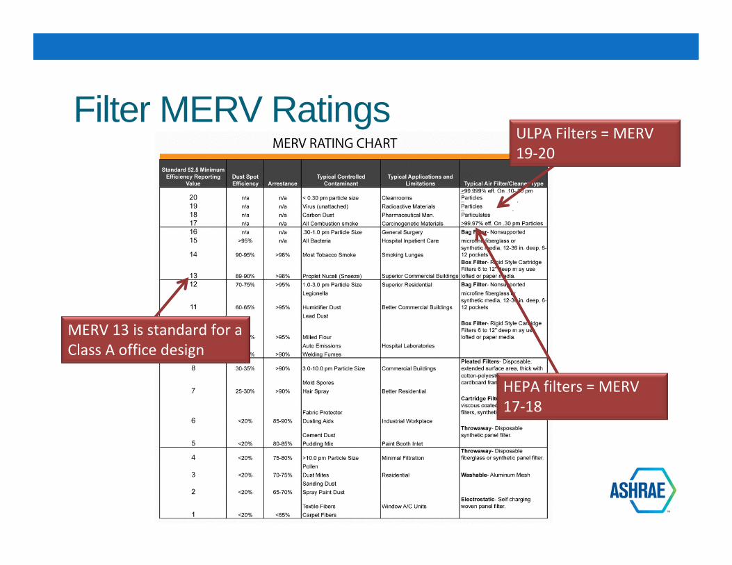
Filter MERV Ratings
MERV 13 is standard for a Class A office design
ULPA Filters = MERV 19‐20
HEPA filters = MERV 17‐18

Filter Media
Glass fiber paper technology
Today’s micro‐pleat media technology allows for lower pressure drop and reduced filter media depth
Older generations of HEPA filters used aluminum pleat separators

Airborne Particulate Cleanliness Classifications
ISO 14644‐1 FEDERAL STANDARD 209E
ISO Class English Metric
ISO 1
ISO 2
ISO 3 1 M1.5
ISO 4 10 M2.5
ISO 5 100 M3.5
ISO 6 1,000 M4.5
ISO 7 10,000 M5.5
ISO 8 100,000 M6.5
ISO 9 N/A N/A
Standard 209E classifications are out‐of‐date. This standard was officially retired in 2001.
Incr
easi
ng C
lean
lines
s

Airborne Particulate CleanlinessCLASS
Number of Particles per Cubic Meter by Micrometer Size
0.1 micron 0.2 micron 0.3 micron 0.5 micron 1 micron 5 microns
ISO1 10 2
ISO2 100 24 10 4
ISO3 1,000 237 102 35 8
ISO4 10,000 2,370 1,020 352 83
ISO5 100,000 23,700 10,200 3,520 832 29
ISO6 1,000,000 237,000 102,000 35,200 8,320 293
ISO7 352,000 83,200 2,930
ISO8 3,520,000 832,000 29,300
ISO9 35,200,000 8,320,000 293,000
Perspective: A strand of human hair is about 40‐100 microns in diameter.
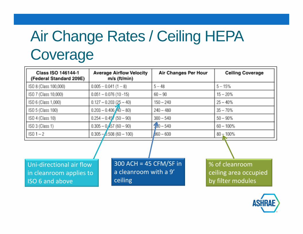
Air Change Rates / Ceiling HEPA Coverage
% of cleanroom ceiling area occupied by filter modules
300 ACH = 45 CFM/SF in a cleanroom with a 9’ceiling
Uni‐directional air flow in cleanroom applies to ISO 6 and above

Case Study Introductory Notes
Project specifics – location, company, etc. are confidential.
Photos used in this presentation are generic, unless otherwise noted.
The Case Study project was delivered to the Owner as a design‐assist, with contractor involvement early in the design process.

Design Criteria – Clean RoomISO Class 6 Environment:
36,000 SF open‐bay type cleanroom Positive room pressure controlled to
+0.05” WC Room conditions at 69°F and 40% RH Minimum of 120 air‐changes per hour 33% ceiling HEPA coverage Unidirectional vertical airflow 12’ ceiling height
Room features: Smooth, cleanable interior surfaces Gasketed grid ceiling with luminaires, HEPA modules, and systems
components (sprinkler heads, smoke detectors, etc.), smoke exhaust grilles Perforated floor serves as return air path Wafer manufacturing tools with specialized solvent and acid exhaust systems

HVAC Design – Clean RoomMake‐up Air AHUs: 100% outside air delivery to plenum Temperature and humidity control of
make‐up air (6) units, each sized for 30,000 CFM Make‐up air flow is 5 CFM/SF, or 25 ACH.
Recirculating AHUs: (40) units, each sized for 24,000 CFM Recirculated air flow is 26.7 CFM/SF, or
133 ACH. Powder‐coated finish
Exhaust Systems: Acid Exhaust (2.8 CFM/SF), with scrubbers and N+1 redundancy Solvent Exhaust (0.8 CFM/SF), N+1 redundancy. Smoke Exhaust (2.7 CFM/SF)

Building Cross-section
ISO Class 6 Cleanroom
Recirculating AHU’s Ducted HEPA terminals
Make‐up AHU’s
This multi‐level configuration is often applied to more stringent ISO cleanroom classifications.
Perforated floor slab for RA path

Manufacturing Level Ceiling Plan
Overall Ceiling HEPA coverage is 33%
HEPA filter module arrangement in a 2’ X 4’ clean‐room sealed ceiling grid

Filter TerminalsSA connection –AHU supply fan provides required static
Knife‐edge seal with gel gasket
Filter media
Balancing damper, accessible from the manufacturing level

Interstitial Level Plan
Supply air plenums with multiple take‐off fittings to HEPA ceiling modules
Actual project photo
Supply air plenums are connected to provide a level of redundancy between recirculation units.

Fan Attic Level Plan
Make‐up air units, with outside air hoods above
Exhaust mains
The entire fan attic level serves as a mixed air plenum.
Recirculated air units, with downward discharge to supply plenums at the Interstitial level.
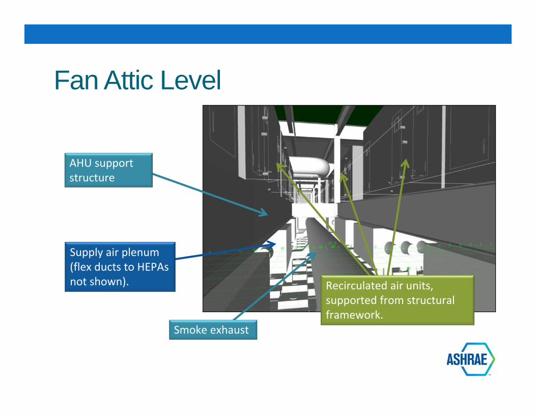
Fan Attic Level
Smoke exhaust
Recirculated air units, supported from structural framework.
Supply air plenum (flex ducts to HEPAs not shown).
AHU support structure

Clean Room Make-up Air UnitsOutside air make‐up AHU design with complete temperature and humidity control.
Outside air from roof hood
Direct‐drive fan array (4 fans) (535 CFM/BHP), N+1
8‐row, 8 FPI cooling coil sized for 400 FPM face velocity and 0.83” DP
Units are scheduled for 8.0” TSP, and only 0.75” ESP.
Air is HEPA filtered to maximize the service life of terminal HEPAs
Pre‐ and intermediate filtration
8‐row, 10 FPI dehumidification coil sized for 400 FPM face velocity and 1.13” DP

Fan Array Technology
Many advantages over single‐fan systems:
Equipment redundancy Less vibration Lower noise Less space required Tighter duty selection Direct drive fans – no belt
loss

Psychrometrics – Make-up Air UnitsMake‐up Air AHU cooling coil:EA = 85°F db/70°F wbLA = 52°F db/52°F wb
Room conditions:69°F db/40% RH
Make‐up Air AHU dehumidification coil:EA = 53°F db/53°F wbLA = 42°F db/42°F wb
Make‐up Air AHU Reheat Coil:EA = 41°F dbLA = 72°F db
Outside air conditions at Maximum wb temp and coincident db temp

Clean Room Recirculation UnitsSimple, low‐pressure recirculating AHU design with very low unit pressure drop
Units are scheduled for 3.0” TSP, which includes terminal HEPA DP.
Direct‐drive fan with custom wheel width(1500 CFM/BHP)
3‐row, 8 FPI cooling coil sized for 400 FPM maximum face velocity and 0.17” DP
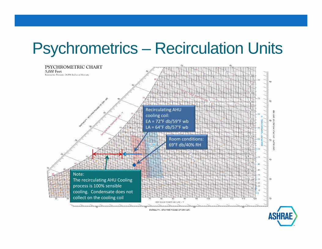
Psychrometrics – Recirculation Units
Recirculating AHU cooling coil:EA = 72°F db/59°F wbLA = 64°F db/57°F wb
Room conditions:69°F db/40% RH
Note:The recirculating AHU Cooling process is 100% sensible cooling. Condensate does not collect on the cooling coil

Energy Efficiency ConsiderationsCleanrooms can easily be 50X more energy‐intensive than typical office space, and that is heavily impacted by the fan energyrequired to deliver the prescribed air‐change rate at the required filtration level. The room cooling load is often a small fraction of the energy demand. Things to prioritize:1. Efficient fan selection – direct‐drive, with
custom wheel selection2. High‐efficiency fan motors3. Low system pressure drop – size ductwork
for low velocity and minimize length of duct runs
4. Low component pressure drop – keep air velocity (and pressure drop) across coils and filters as low as practical
Fan Energy
Cooling Energy
Power
Lighting

Other Energy Efficiency ConsiderationsOther design considerations:1. AHU cooling coils are sized for a low face velocity
(400 FPM) and air temperature drop (less than 8°F), which allows coil selections to have 3 rows/8 FPI, and minimized pressure drop (0.17” WC) as a result.
2. Because cooling coil temperature drop is minimized, chilled water supply temperature can be increased (57°F) during mild and cold weather, which further increases the efficiency of the chilled water plant.
3. Pre‐filters: Intended to maximize the life‐span of the HEPA terminal filters. 400 FPM face velocity.
4. Supply fan speeds are modulated through VFDs as a function of filter loading.
5. Limiting the cleanroom ceiling height to 12’ helps minimize the CFM required to maintain ACH rates.
Chilled water coil

Specialty Exhaust Systems
Acid and solvent exhaust systems: Epoxy‐lined stainless‐steel exhaust ductwork with welded seams and flanged connections. Acid exhaust stream is routed through a scrubber system prior to being discharged at high velocity vertical plume discharge at roof level.
Note the structureabove is the perforated floor /return air path
Actual project photo – Sub-Fab Level
Recommended References:
ASHRAE Applications Volume, Chapter 18: Clean Spaces
ISO Cleanroom Standards Manufacturer web‐sites:
Cam‐fil (filters)Flanders (filters)Price Design Guide (air devices)

Questions?

Thank you!

Contact Information
Barry J. Stamp, PE, LEED APDirector of Engineering ServicesU.S. Engineering Company303‐629‐[email protected]