casing spacer technology leaders
TRANSCRIPT

NORTH AMERICA
Casing Spacer Technology Leaders
Benefit today. Save down the line.
www.racispacers.com

2
Our uniquely designed, engineered and patented spacers are widely respected and our dependability has made us the number one choice of specifiers and installers worldwide.
Our ISO 9001:2000 CERTIFICATION ensures that Raci Spacers consistently provides our customers with the highest standard of products and service.
Raci has been the global leader in casing spacer technology since 1952.
3
Why Raci
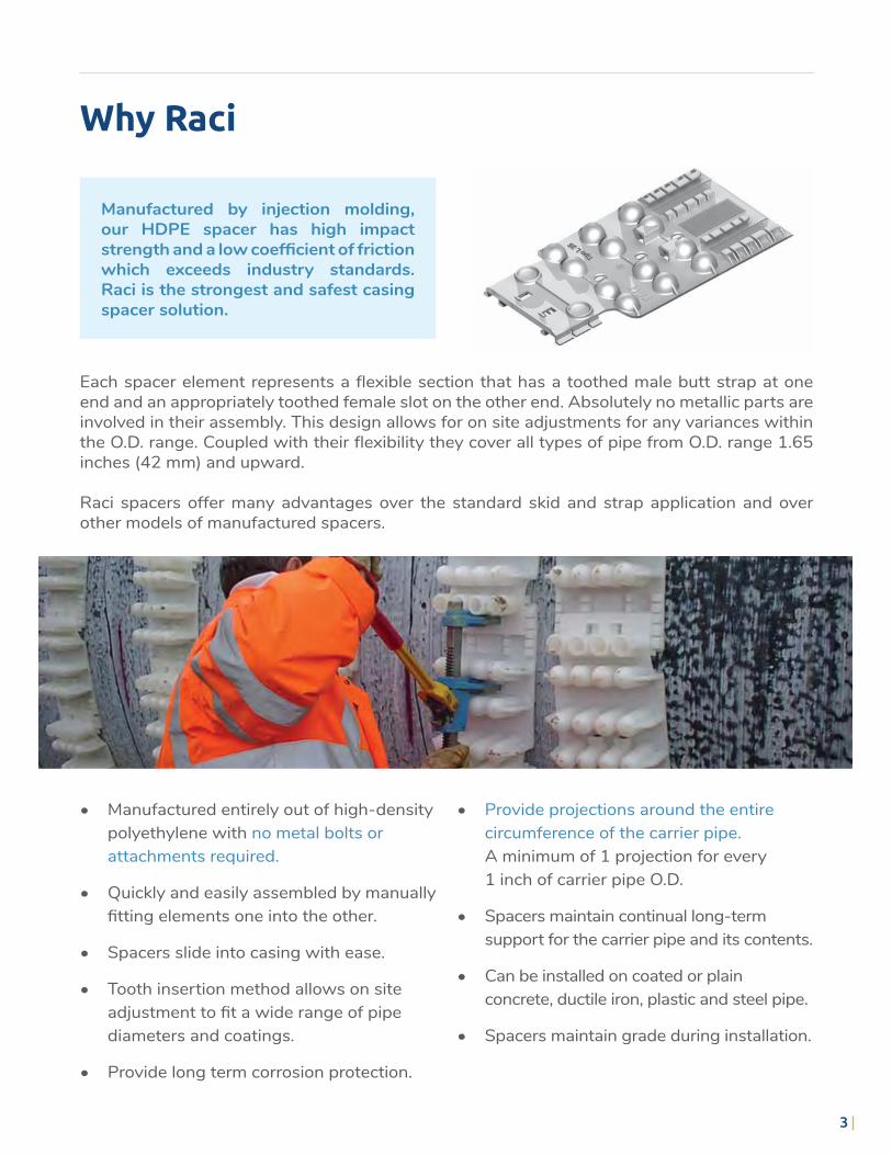
Manufactured by injection molding, our HDPE spacer has high impact strength and a low coefficient of friction which exceeds industry standards. Raci is the strongest and safest casing spacer solution.
Each spacer element represents a flexible section that has a toothed male butt strap at one end and an appropriately toothed female slot on the other end. Absolutely no metallic parts are involved in their assembly. This design allows for on site adjustments for any variances within the O.D. range. Coupled with their flexibility they cover all types of pipe from O.D. range 1.65 inches (42 mm) and upward.
Raci spacers offer many advantages over the standard skid and strap application and over other models of manufactured spacers.
• Manufactured entirely out of high-density polyethylene with no metal bolts or attachments required.
• Quickly and easily assembled by manually fitting elements one into the other.
• Spacers slide into casing with ease.
• Tooth insertion method allows on site adjustment to fit a wide range of pipe diameters and coatings.
• Provide long term corrosion protection.
• Provide projections around the entire circumference of the carrier pipe. A minimum of 1 projection for every 1 inch of carrier pipe O.D.
• Spacers maintain continual long-term support for the carrier pipe and its contents.
• Can be installed on coated or plain concrete, ductile iron, plastic and steel pipe.
• Spacers maintain grade during installation.

4
Choosing a Spacer
Casing spacers are used to install carrier pipe inside the encasement pipe in order to provide support around the periphery of the pipe as it naturally rotates while being pushed through the casing.
The innovation and engineering behind Raci Spacers provides you with the best long-term protection.
Yield Strength
Tensile Strength
Hardness shore D
Dielectric strength
Elongation at break
Min working temperature
UVL stabilization
Physical characteristics Raci High Density Polyethylene Spacers
25 N/mm2
20 N/mm2
65
>37 Kv/mm
200%
-20˚ C
yes
3625 PSI
2900 PSI
65
>940 Kv/inch
200%
-4˚ F
yes
ASTM D 638
ASTM D 638
ASTM D 2240
ASTM 149/64
ASTM D 638
-
-

5
Raci casing spacers and dual containment pipe spacers are available for pipe sizes 1.65“ (42 mm) and upward. Our customers around the world use Raci Spacers for a range of applications:
All Raci insulators and spacers meet the following criteria for separating casing and carrier pipes:
Customers around the world choose Raci spacers for a wide range of applications
• Municipal water pipe and water transmission pipeline cased crossings.
• Drainage lines that need to be protected and in double containment.
• Oil and gas pipeline cased crossings and casings along highways, roads and railroads.
• Municipal sewer pipe cased crossings.
• Dual containment pipe application for waste water and hazardous materials (for concentrated hazardous materials please contact your distributor for chemical resistance tables).
• Ensures electrical insulation between the two pipes.
• Fastens tightly on the carrier pipe to ensure no horizontal movement during insertion.
• Resistant to both mechanical and thermal shocks and stresses particularly during installation.
• Made of materials which do not conduct electricity and are permanently resistant to chemical corrosion.
• Permanently prevent bells from sliding or resting on casing pipe.
• Provide constant projections around the entire circumference of the carrier pipe. A minimum of 1 projection for every 1 inch of carrier pipe O.D.
On request spacers can be manufactured in other types of plastic material according to the mechanical and temperature requirements of the application.
SPECIAL APPLICATIONS

6
Choosing a Spacer
With the information below and using our selection charts, the type and number of spacer elements required for each ring and how far they will be spaced can be determined.
Up to 200 mm or 7 inUp to 280 mm or 11 in
S/T or C/D/IA/BSmall
Up to 530 mm or 20 inUp to 1000 mm or 38 in
F/GM/N or P/QMedium
Up to 1750 mm or 68 inUp to 3400+ mm or 134+ in
LE/HLarge
SIZE CARRIER PIPE O.D. RECOMMENDED SOLUTION
• Clearance desired between casing and carrier pipe.
• Length of application.
• Linear weight of filled carrier pipe.
• Exact bell, flange or coupling O.D.
• Exact carrier pipe O.D.
• Exact casing Pipe I.D.
Appropriate spacer selection and installation provides the best long-term protection.
Spacer selection simplified.

7
Formulas
Our basic formulas below will help you choose the correct Raci Spacer element.
1casing pipe ID – carrier pipe O.D. / 2 will give you the desired range for element height.
Go to the table that best addresses the carrier pipe O.D. and load carrying capacity to determine the different heights that are available within that style.
FORMULA ONETo determine height required
2(carrier pipe O.D.) + (2 times height of element) > O.D. of bell + clearance factor*
*Clearance factor is .6 inches or 15 mm and ensures bell clearance.
FORMULA TWOTo clear the bell
3(carrier pipe O.D.) + (2 times height of element) + clearance factor* < the I.D. of casing pipe
*Clearance factor is .6 inches or 15 mm and ensures insertion ease.
*When working in inches the clearance factor is .6
Once you have determined the element type and the height necessary return to the table to determine the number of elements required to complete a ring.
FORMULA THREEFor insertion ease
4length of application / distance between rings + 3*
*The spacing of Raci spacer rings must ensure that the carrier pipe is fully supported throughout its length.! Please see note on page 13
To guard against the effects of differential loading at the entrance and exit points of the casing, two rings are used at the beginning and end of the casing, regardless of pipe size or length.
FORMULA FOURNumber of rings required
8
Products
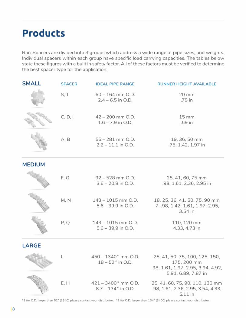
Raci Spacers are divided into 3 groups which address a wide range of pipe sizes, and weights.Individual spacers within each group have specific load carrying capacities. The tables below state these figures with a built in safety factor. All of these factors must be verified to determine the best spacer type for the application.
SMALL
MEDIUM
LARGE
SPACER IDEAL PIPE RANGE RUNNER HEIGHT AVAILABLE
S, T
F, G
L
C, D, I
M, N
E, H
A, B
P, Q
60 – 164 mm O.D.2.4 – 6.5 in O.D.
92 – 528 mm O.D.3.6 – 20.8 in O.D.
450 – 1340 mm O.D.18 – 52 in O.D.
42 – 200 mm O.D.1.6 – 7.9 in O.D.
143 – 1015 mm O.D.5.6 – 39.9 in O.D.
421 – 3400 mm O.D.8.7 – 134 in O.D.
55 – 281 mm O.D.2.2 – 11.1 in O.D.
143 – 1015 mm O.D.5.6 – 39.9 in O.D.
20 mm.79 in
25, 41, 60, 75 mm.98, 1.61, 2.36, 2.95 in
25, 41, 50, 75, 100, 125, 150, 175, 200 mm
.98, 1.61, 1.97, 2.95, 3.94, 4.92, 5.91, 6.89, 7.87 in
15 mm.59 in
18, 25, 36, 41, 50, 75, 90 mm.7, .98, 1.42, 1.61, 1.97, 2.95,
3.54 in
25, 41, 60, 75, 90, 110, 130 mm.98, 1.61, 2.36, 2.95, 3.54, 4.33,
5.11 in
19, 36, 50 mm.75, 1.42, 1.97 in
110, 120 mm4.33, 4.73 in
*1 for O.D. larger than 52” (1340) please contact your distributor. *2 for O.D. larger than 134” (3400) please contact your distributor.
*1
*1
*2
*2

Safe now. Save later.
Our uniquely engineered casing spacers are designed and tested to provide continuous support and protection during installation and over the long-term.
With no metal parts, our injection-molded polyethylene spacers are corrosion-resistant, saving you money in the long run.
Easy to install and field adjustable, our casing spacers are the number one choice of specifiers and installers.
9
10
Assembly & InstallationThis document contains important information for installation of Raci Casing Spacers. Read and understand these before installation. In the event of disagreement between this document and any other installation notes, the information in this document shall prevail. Failure to follow these instructions may limit the success of your Raci Casing Spacer installation.
BEFORE YOU BEGIN
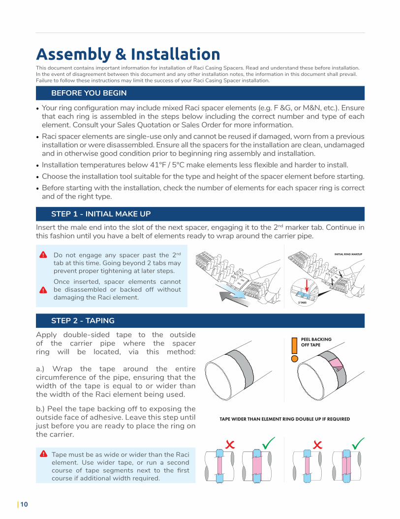
STEP 1 - INITIAL MAKE UP
STEP 2 - TAPING
Insert the male end into the slot of the next spacer, engaging it to the 2nd marker tab. Continue in this fashion until you have a belt of elements ready to wrap around the carrier pipe.
Apply double-sided tape to the outside of the carrier pipe where the spacer ring will be located, via this method: a.) Wrap the tape around the entire circumference of the pipe, ensuring that the width of the tape is equal to or wider than the width of the Raci element being used.
b.) Peel the tape backing off to exposing the outside face of adhesive. Leave this step until just before you are ready to place the ring on the carrier.
2 TABS
INITIAL RING MAKEUPDo not engage any spacer past the 2nd tab at this time. Going beyond 2 tabs may prevent proper tightening at later steps.Once inserted, spacer elements cannot be disassembled or backed off without damaging the Raci element.
Tape must be as wide or wider than the Raci element. Use wider tape, or run a second course of tape segments next to the first course if additional width required.
TAPE WIDER THAN ELEMENT RING DOUBLE UP IF REQUIRED
PEEL BACKINGOFF TAPE
• Your ring configuration may include mixed Raci spacer elements (e.g. F &G, or M&N, etc.). Ensure that each ring is assembled in the steps below including the correct number and type of each element. Consult your Sales Quotation or Sales Order for more information.
• Raci spacer elements are single-use only and cannot be reused if damaged, worn from a previous installation or were disassembled. Ensure all the spacers for the installation are clean, undamaged and in otherwise good condition prior to beginning ring assembly and installation.
• Installation temperatures below 41°F / 5°C make elements less flexible and harder to install.• Choose the installation tool suitable for the type and height of the spacer element before starting. • Before starting with the installation, check the number of elements for each spacer ring is correct
and of the right type.

11
STEP 3 - WRAPPING
STEP 4 - INITIAL TIGHTENING
STEP 5 - FINAL TIGHTENING
STEP 6 - CONTINUE INSTALLATION
CARRIER INSERTION NOTES
Tightening past the 3rd tab at this step may prevent all elements from connecting properly.
Do not use a snipe or cheater bar on the handle of the Raci tool.
Ensure the spacer ring is aligned with the tape, and is not at an angle. For proper engagement, the spacer ring must be square to the carrier pipe.Tape backing must be removed prior to this step.
Use the Raci Tool to tighten each spacer element connection evenly up to the 3rd tab. Periodically check alignment to make sure the spacer ring is still square to the carrier pipe, and is on the tape applied in Step 2.
Continue to work around the spacer ring with the Raci tool to gradually and evenly tighten the ring around the carrier pipe. Each element should have about the same number of tabs engaged.
Repeat Steps 1 - 5, spacing the element rings out per the spacing information provided with the Sales Quotation or Sales Order until the entire carrier pipe has spacer rings installed. Once tightened, the spacer ring and carrier pipe are ready to be installed into the casing.
If carrier pipe is pushed into the casing, note the required number of lead and tail rings on the push, and ensure that these are installed prior to starting.
Wrap the spacer belt loosely around the pipe and close the ends by hand up to the 2nd tab, same as in Step 1.
ENSURE RING SQUARE TO PIPE
90°
Casing Lubrication is strongly recommended. Periodic re-lubrication may be required.Make sure the casing interior and elements are free of dirt, mud and debris prior to push.Just prior to inserting the pipe lengths, make sure to re-tighten each spacer ring just before they are inserted into the casing.
OK!
NO!
NO CHEATERSNO SNIPES
3 TABS MIN.

12
SmallRaci Spacer Options:
Type S, T 20 mm element support height of .79 inchesO.D. range inches O.D. range mm No. of elements to make a ring
min max min max S T
2.32 2.67 59 68 2 -2.71 2.95 69 75 1 12.99 3.30 76 84 - 23.46 4.01 88 102 3 -4.06 4.21 103 107 2 14.25 4.48 108 114 1 24.53 4.72 115 120 - 34.76 5.19 121 132 4 -5.24 5.51 133 140 3 15.55 5.74 141 146 2 25.79 5.98 147 152 1 36.02 6.61 153 168 - 4
MAXIMUM LOAD MUST NOT EXCEED 250 LBS/110 KG PER RING
Type C, D, I 15 mm element support height of .59 inchesO.D. range inches O.D. range mm No. of elements to make a ring
min max min max C D I
1.65 2.05 42 52 - - 12.28 3.15 58 80 1 - -3.19 3.90 81 99 - 1 -3.94 5.24 100 133 1 - 1
5.28 6.69 134 170 1 1 -6.73 7.87 171 200 - 2 -
MAXIMUM LOAD MUST NOT EXCEED 440 LBS/200 KG PER RING
Type A,B 19, 36, 50 mmO.D. range inches O.D. range mm No. of elements to make a ring
min max min max A B
2.17 2.52 55 64 - 22.36 2.76 60 70 1 12.68 3.03 68 77 2 -3.35 3.86 85 98 - 33.54 4.17 90 106 1 23.86 4.57 98 116 3 -4.65 5.20 118 132 - 44.92 5.51 125 140 1 35.51 6.22 140 158 4 -6.22 7.09 158 180 2 37.01 7.87 178 200 5 -7.87 9.45 200 240 - 78.46 9.53 215 242 6 -9.41 10.71 239 272 6 19.65 11.06 245 281 7 -
Elements Runner Height In.
Max Load Per Ring
Lbs KgA/B 19 0.75 770 350A/B 36 1.42 550 250A/B 50 1.97 440 200

13
MediumRaci Spacer Options:
Type F, G 25, 41, 60, 75 mmO.D. range inches O.D. range mm No. of elements to make a ring
min max min max F G
3.62 4.53 92 115 1 14.57 5.98 116 152 2 -6.02 7.40 153 188 2 17.44 8.82 189 224 3 -8.86 10.24 225 260 3 1
10.28 11.61 261 295 4 -11.65 12.32 296 313 4 112.36 14.80 314 376 5 -14.84 17.56 377 446 6 -17.60 20.79 447 528 7 -
Elements Runner Height In.
Max Load Per Ring
Lbs KgF/G 25 0.98 1540 700F/G 41 1.61 1870 850F/G 60 2.36 1870 850F 75 2.95 1870 850
Type M, N 18, 25, 36, 41, 50, 75, 90 mm Type P, Q 110, 120 mmO.D. range inches O.D. range mm No. of elements to make a ring
min max min max M/P N/Q
5.63 6.61 143 168 1 16.65 7.91 169 201 2 -7.95 8.94 202 227 1 28.98 9.92 228 252 2 19.96 11.26 253 286 3 -
11.30 12.24 287 311 2 212.28 13.27 312 337 3 113.31 15.55 338 395 4 -15.59 16.57 396 421 4 116.61 19.88 422 505 5 -19.92 23.23 506 590 6 -23.27 26.54 591 674 7 -26.57 29.88 675 759 8 -29.92 36.02 760 915 9 -33.46 39.96 850 1015 10 -
Elements Runner Height In.
Max Load Per Ring
Lbs KgM/N 18 0.70 2425 1100M/N 25 0.98 2535 1150M/N 36 1.42 4400 2000M 41 1.61 3968 1800M/N 50 1.97 3638 1650M/N 75 2.95 4300 1950M/N 90 3.54 3858 1750P/Q 110 4.33 2315 1050P/Q 120 4.72 2200 1000
! Please see note on page 13

14
Type L 25, 41, 50, 75, 100, 125, 150, 175, 200O.D. range inches O.D. range mm No. of elements to make a ring
min max min max L
17.72 20.07 450 510 521.26 24.01 540 610 624.61 28.14 625 715 728.15 31.69 715 805 831.69 35.23 805 895 935.24 38.77 895 985 1038.78 42.32 985 1075 1142.32 45.66 1075 1160 1245.67 49.21 1160 1250 1349.21 52.75 1250 1340 1452.76 56.29 1340 1430 1556.30 59.84 1430 1520 1659.84 63.38 1520 1610 1763.39 68.89 1610 1750 18
Elements Runner Height In.
Max Load Per Ring
Lbs KgL 25, 41, 50 0.98, 1.61, 1.97 6600 3000
L 75 2.95 5500 2500L 100 3.94 5500 2500L 125 4.92 4400 2000
L 150, 175, 200 5.91, 6.89, 7.87 3300 1500
Type E and H 25, 41, 60, 75, 90, 110 and 130 mmO.D. range inches O.D. range mm No. of elements to make a ring
min max min max E H
16.58 18.30 421 465 4 118.35 20.86 466 530 5 -20.91 24.80 531 630 6 -24.84 28.74 631 730 7 -28.78 32.67 731 830 8 -32.29 35.82 820 910 9 -35.83 40.55 910 1030 10 -40.59 45.62 1031 1159 11 -45.67 53.54 1160 1360 13 -53.58 62.99 1361 1600 15 -63.03 70.82 1601 1799 17 -70.87 83.07 1800 2110 20 -83.11 95.66 2111 2430 23 -95.71 112.59 2431 2860 27 -
112.64 134.40 2861 3414 32 -
Elements Runner Height In.
Max Load Per Ring
Lbs KgE/H 25, 41, 60 0.98, 1.61, 2.36 11000 5000
E/H 75 2.95 8800 4000E/H 90 3.54 9000 4100
E/H 110 4.33 7600 3450E/H 130 5.11 7150 3250
*1
*1 for O.D. larger than 134” (3400) please contact your distributor
LargeRaci Spacer Options:

15
Specifications
The spacers should be of a projection type that has a minimum number of projections around the circumference that total the number of diameter inches. For example: 8” pipe should have a minimum of 8 projections and 18” pipe should have a minimum of 18 projections.
Spacing between spacer rings (span) should be calculated based on the actual installed load (weight of pipe filled with liquid) but should not exceed 10 feet/ 3 meters. Refer to the tables for the load carrying capacity of each type of Raci spacer used.
Spacer should also have a minimum height that clears the pipe bell or as otherwise indicated on the plans.
Casing spacers should be projection type – non metallic spacers constructed of preformed sections of high-density polyethylene. Spacers should be ISO 9001:2000 certified for strength and quality.
Casing spacers should be installed using double backed tape provided with the spacers in order to fasten them tightly to the carrier pipe.
! Distance between spacers must be calculated so the maximum load per spacer ring does not exceed the max. load carrying capacity for the type used as shown in the tables. Maximum load per spacer is calculated based
on the weight of the pipe filled with liquid divided by the number of spacer rings installed. The maximum distance of 10 feet/ 3 metres shall not be exceeded due to the danger of the pipe sagging between the spacers support points unless the pipe manufacturer states differently.

Phone: 1-800-900-6045 www.racispacers.com
Raci Spacers North America Inc.
NORTH AMERICA