cass everitt nvidia corporation [email protected] shadow mapping
TRANSCRIPT
2
Motivation forBetter Shadows
• Shadows increase scene realism• Real world has shadows• Other art forms recognize the value of
shadows
• Shadows provide important depth cues

3
Common Real-timeShadow Techniques
ShadowShadowvolumesvolumes
Light mapsLight maps
ProjectedProjectedplanarplanarshadowsshadows
HybridHybridapproachesapproaches
4
Problems with CommonShadow Techniques
• Mostly tricks with lots of limitations• Projected planar shadows
• well works only on flat surfaces• Stenciled shadow volumes
• determining accurate, water-tight shadow volume is hard work
• Light maps
• totally unsuited for dynamic shadows• In general, hard to get everything shadowing
everything
5
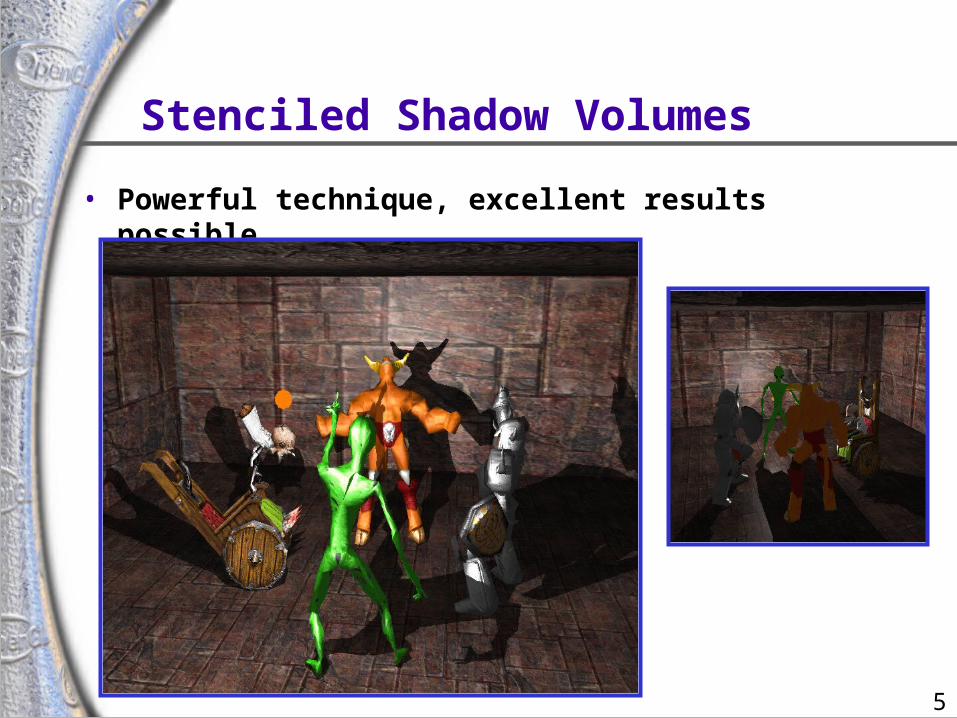
Stenciled Shadow Volumes
• Powerful technique, excellent results possible
6
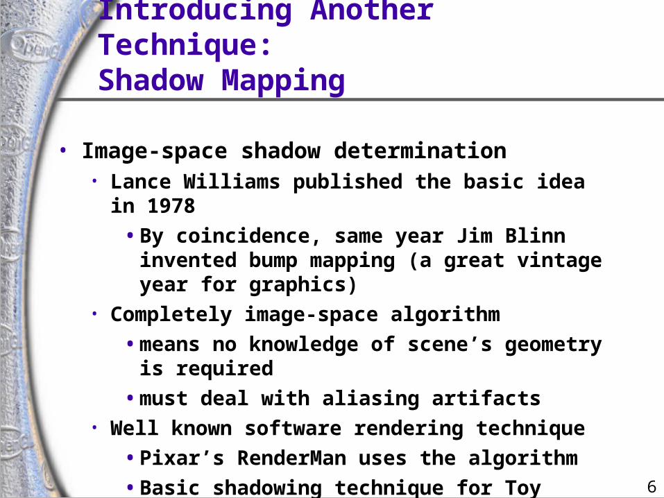
Introducing Another Technique:Shadow Mapping
• Image-space shadow determination• Lance Williams published the basic idea in 1978
• By coincidence, same year Jim Blinn invented bump mapping (a great vintage year for graphics)
• Completely image-space algorithm
• means no knowledge of scene’s geometry is required
• must deal with aliasing artifacts• Well known software rendering technique
• Pixar’s RenderMan uses the algorithm
• Basic shadowing technique for Toy Story, etc.
7
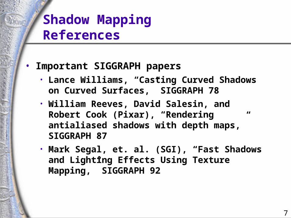
Shadow MappingReferences
• Important SIGGRAPH papers• Lance Williams, “Casting Curved Shadows on
Curved Surfaces,” SIGGRAPH 78• William Reeves, David Salesin, and Robert Cook
(Pixar), “Rendering antialiased shadows with depth maps,” SIGGRAPH 87
• Mark Segal, et. al. (SGI), “Fast Shadows and Lighting Effects Using Texture Mapping,” SIGGRAPH 92
8
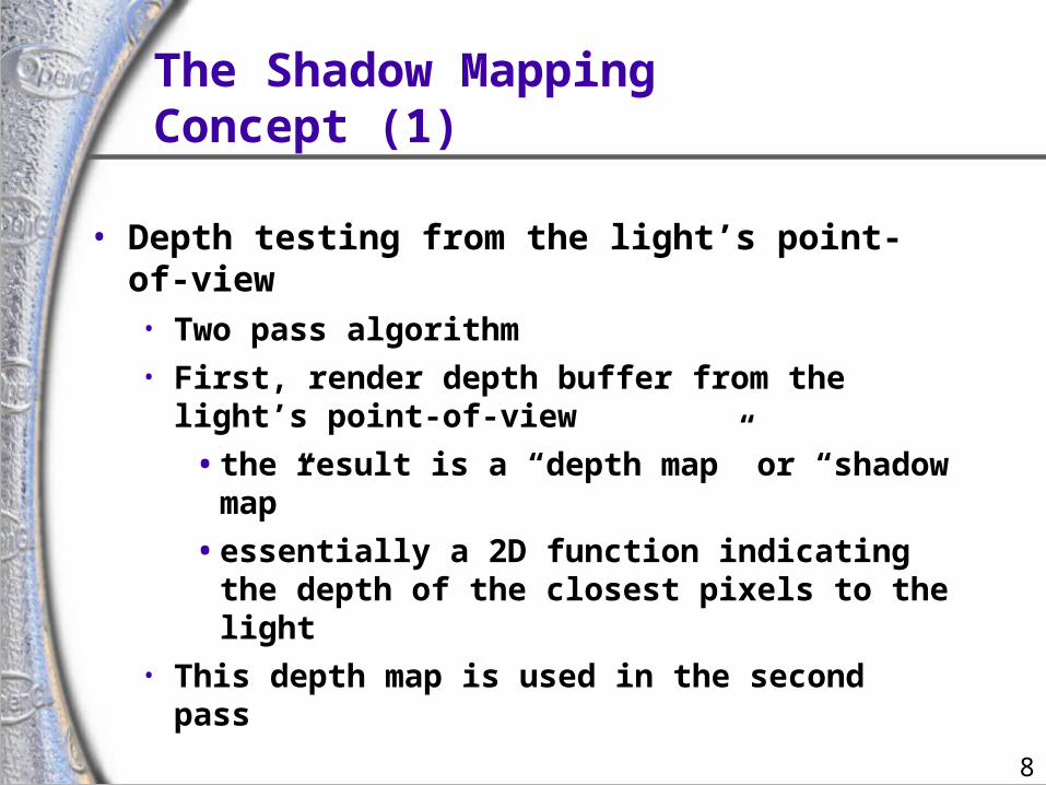
The Shadow MappingConcept (1)
• Depth testing from the light’s point-of-view• Two pass algorithm• First, render depth buffer from the light’s point-of-
view
• the result is a “depth map” or “shadow map”
• essentially a 2D function indicating the depth of the closest pixels to the light
• This depth map is used in the second pass
9
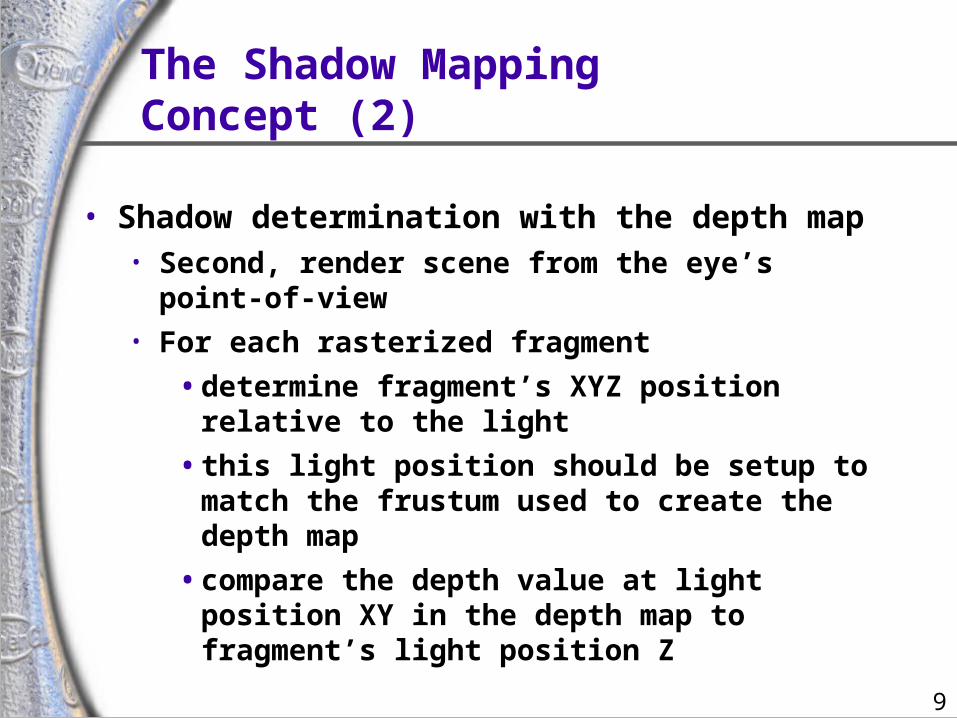
The Shadow MappingConcept (2)
• Shadow determination with the depth map• Second, render scene from the eye’s point-of-view• For each rasterized fragment
• determine fragment’s XYZ position relative to the light
• this light position should be setup to match the frustum used to create the depth map
• compare the depth value at light position XY in the depth map to fragment’s light position Z
10
The Shadow MappingConcept (3)
• The Shadow Map Comparison• Two values
• A = Z value from depth map at fragment’s light XY position
• B = Z value of fragment’s XYZ light position
• If B is greater than A, then there must be something closer to the light than the fragment
• then the fragment is shadowed
• If A and B are approximately equal, the fragment is lit

11
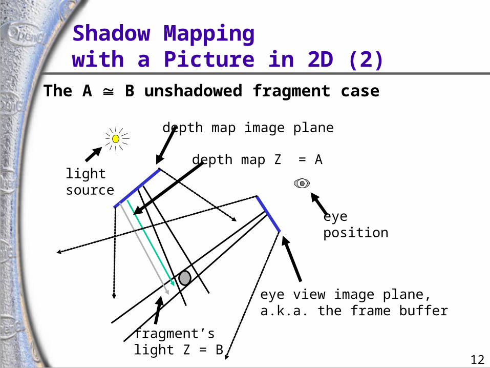
Shadow Mappingwith a Picture in 2D (1)
lightsource
eyeposition
depth map Z = A
fragment’slight Z = B
depth map image plane
eye view image plane,a.k.a. the frame buffer
The A < B shadowed fragment case
12
Shadow Mappingwith a Picture in 2D (2)
lightsource
eyeposition
depth map Z = A
fragment’slight Z = B
depth map image plane
eye view image plane,a.k.a. the frame buffer
The A B unshadowed fragment caseThe A B unshadowed fragment case
13
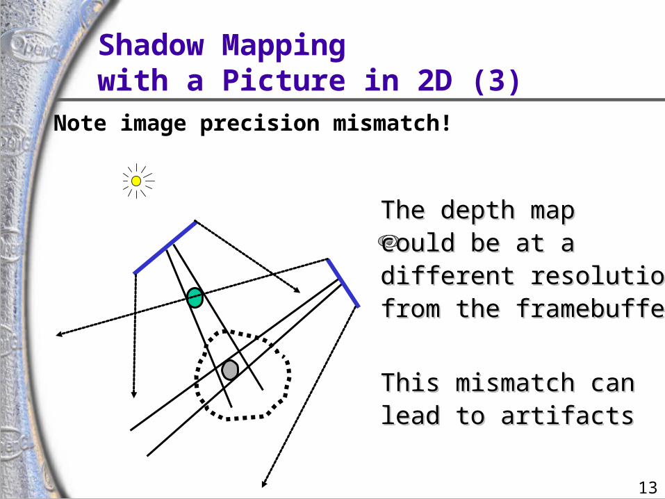
Note image precision mismatch!Note image precision mismatch!
The depth mapThe depth mapcould be at acould be at adifferent resolutiondifferent resolutionfrom the framebufferfrom the framebuffer
This mismatch canThis mismatch canlead to artifactslead to artifacts
Shadow Mappingwith a Picture in 2D (3)
14
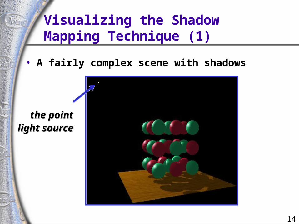
Visualizing the ShadowMapping Technique (1)
• A fairly complex scene with shadows
the pointthe pointlight sourcelight source
15
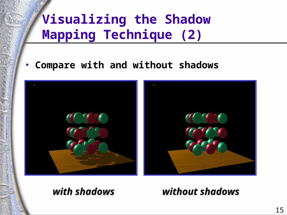
Visualizing the ShadowMapping Technique (2)
• Compare with and without shadows
with shadowswith shadows without shadowswithout shadows
16
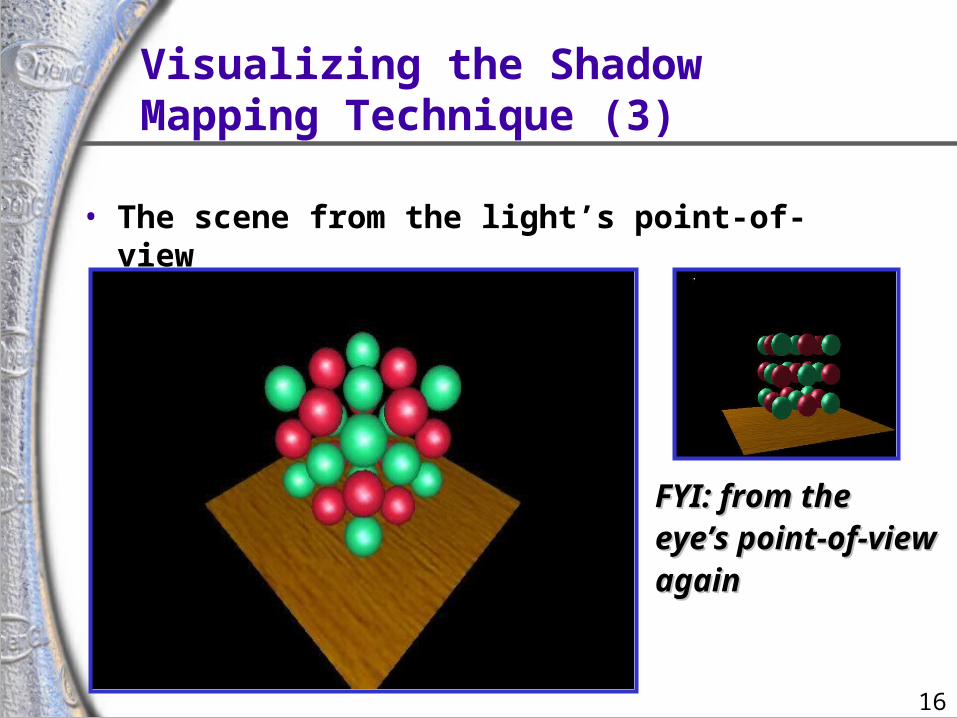
Visualizing the ShadowMapping Technique (3)
• The scene from the light’s point-of-view
FYI: from theFYI: from theeye’s point-of-vieweye’s point-of-viewagainagain
17
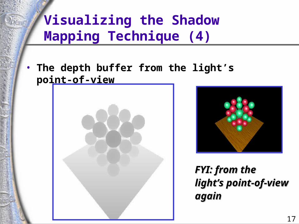
Visualizing the ShadowMapping Technique (4)
• The depth buffer from the light’s point-of-view
FYI: from theFYI: from thelight’s point-of-viewlight’s point-of-viewagainagain
18
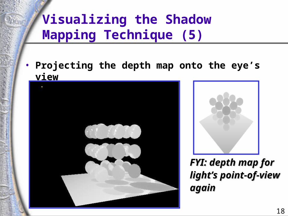
Visualizing the ShadowMapping Technique (5)
• Projecting the depth map onto the eye’s view
FYI: depth map forFYI: depth map forlight’s point-of-viewlight’s point-of-viewagainagain
19
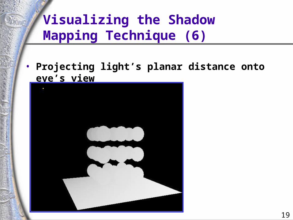
Visualizing the ShadowMapping Technique (6)
• Projecting light’s planar distance onto eye’s view
20
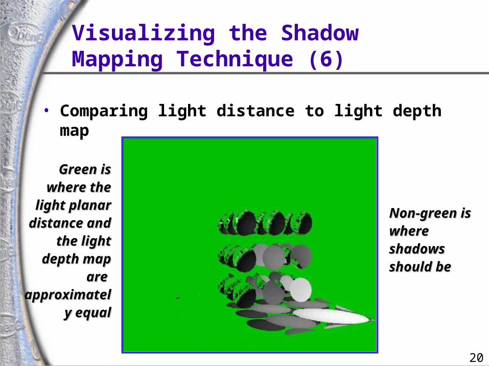
Visualizing the ShadowMapping Technique (6)
• Comparing light distance to light depth map
Green is Green is where the where the
light planar light planar distance and distance and
the light the light depth map depth map
are are approximatelapproximatel
y equaly equal
Non-green is Non-green is where where shadows shadows should beshould be
21
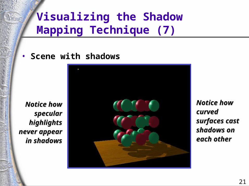
Visualizing the ShadowMapping Technique (7)
• Scene with shadows
Notice how Notice how specular specular
highlights highlights never appear never appear
in shadowsin shadows
Notice how Notice how curved curved surfaces cast surfaces cast shadows on shadows on each othereach other
22
ConstructLight View Depth Map
• Realizing the theory in practice• Constructing the depth map
• use existing hardware depth buffer
• use glPolygonOffset to offset depth value back
• read back the depth buffer contents• Depth map can be copied to a 2D texture
• unfortunately, depth values tend to require more precision than 8-bit typical for textures
• depth precision typically 16-bit or 24-bit
23
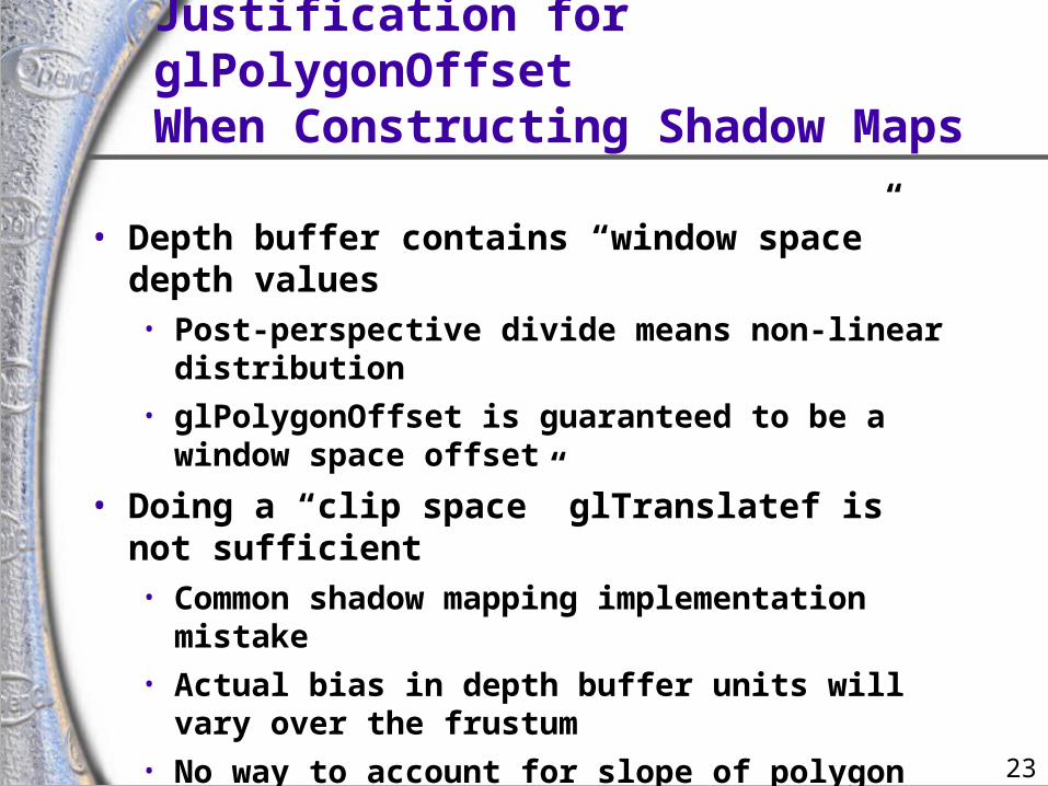
Justification for glPolygonOffsetWhen Constructing Shadow Maps
• Depth buffer contains “window space” depth values• Post-perspective divide means non-linear
distribution• glPolygonOffset is guaranteed to be a window
space offset
• Doing a “clip space” glTranslatef is not sufficient• Common shadow mapping implementation mistake• Actual bias in depth buffer units will vary over the
frustum• No way to account for slope of polygon
24
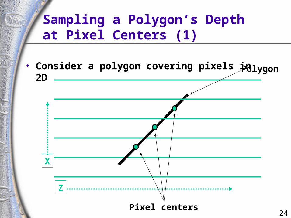
Sampling a Polygon’s Depthat Pixel Centers (1)
• Consider a polygon covering pixels in 2D
X
Z
Pixel centers
Polygon
25
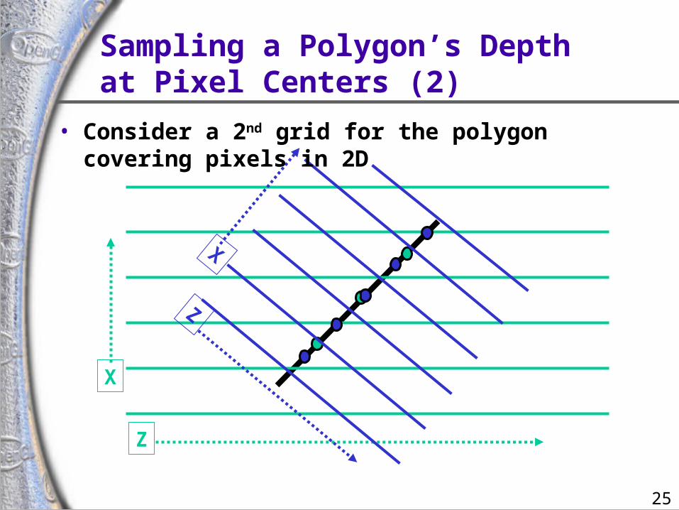
Sampling a Polygon’s Depthat Pixel Centers (2)
X
Z
X
Z
• Consider a 2nd grid for the polygon covering pixels in 2D
26
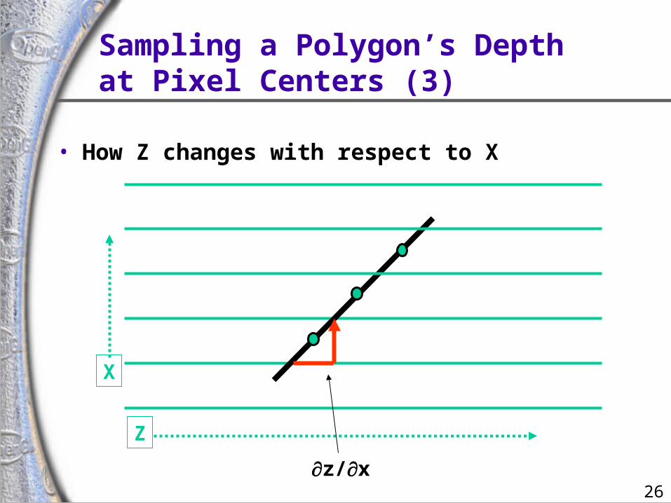
Sampling a Polygon’s Depthat Pixel Centers (3)
• How Z changes with respect to X
X
Z
z/x
27
Why You NeedglPolygonOffset’s Slope
• Say pixel center is re-sampled to another grid• For example, the shadow map texture’s grid!
• The re-sampled depth could be off by +/-0.5 z/x and +/-0.5 z/y
• The maximum absolute error would be | 0.5 z/x | + | 0.5 z/y | max( | z/x | , | z/y | )• This assumes the two grids have pixel footprint area
ratios of 1.0• Otherwise, we might need to scale by the ratio
• Exactly what polygon offset’s “slope” depth bias does
28
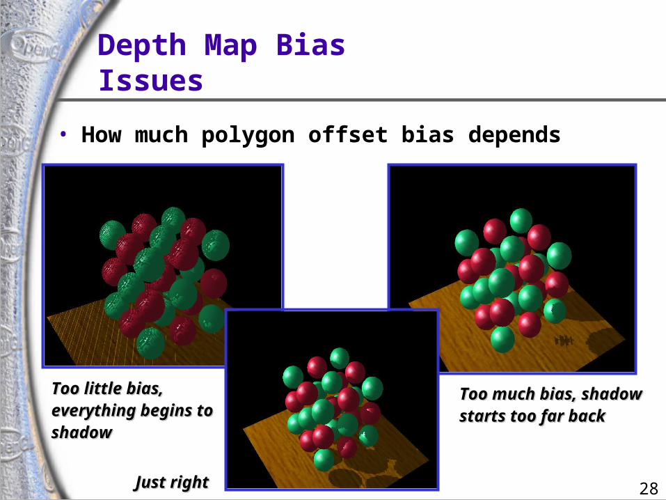
Depth Map BiasIssues
• How much polygon offset bias depends
Too little bias,Too little bias,everything begins toeverything begins toshadowshadow
Too much bias, shadowToo much bias, shadowstarts too far backstarts too far back
Just rightJust right
29
Selecting theDepth Map Bias
• Not that hard• Usually the following works well
• glPolygonOffset(scale = 1.1, bias = 4.0)• Usually better to error on the side of too much bias
• adjust to suit the shadow issues in your scene• Depends somewhat on shadow map precision
• more precision requires less of a bias• When the shadow map is being magnified, a larger
scale is often required
30
Render Scene andAccess the Depth Texture
• Realizing the theory in practice• Fragment’s light position can be generated using
eye-linear texture coordinate generation
• specifically OpenGL’s GL_EYE_LINEAR texgen
• generate homogenous (s, t, r, q) texture coordinates as light-space (x, y, z, w)
• T&L engines such as GeForce accelerate texgen!
• relies on projective texturing
31
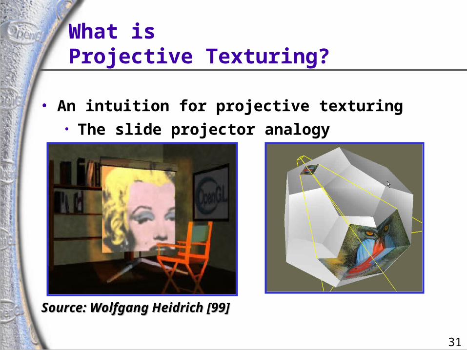
What isProjective Texturing?
• An intuition for projective texturing• The slide projector analogy
Source: Wolfgang Heidrich [99]Source: Wolfgang Heidrich [99]
32
AboutProjective Texturing (1)
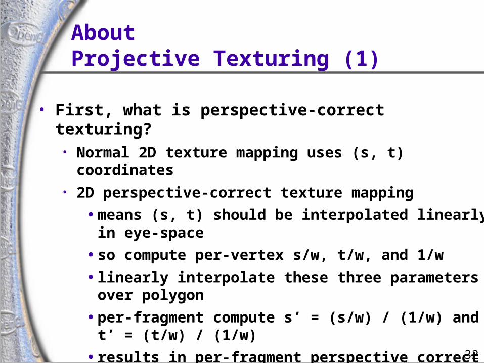
• First, what is perspective-correct texturing?• Normal 2D texture mapping uses (s, t) coordinates• 2D perspective-correct texture mapping
• means (s, t) should be interpolated linearly in eye-space
• so compute per-vertex s/w, t/w, and 1/w
• linearly interpolate these three parameters over polygon
• per-fragment compute s’ = (s/w) / (1/w) and t’ = (t/w) / (1/w)
• results in per-fragment perspective correct (s’, t’)
33
AboutProjective Texturing (2)
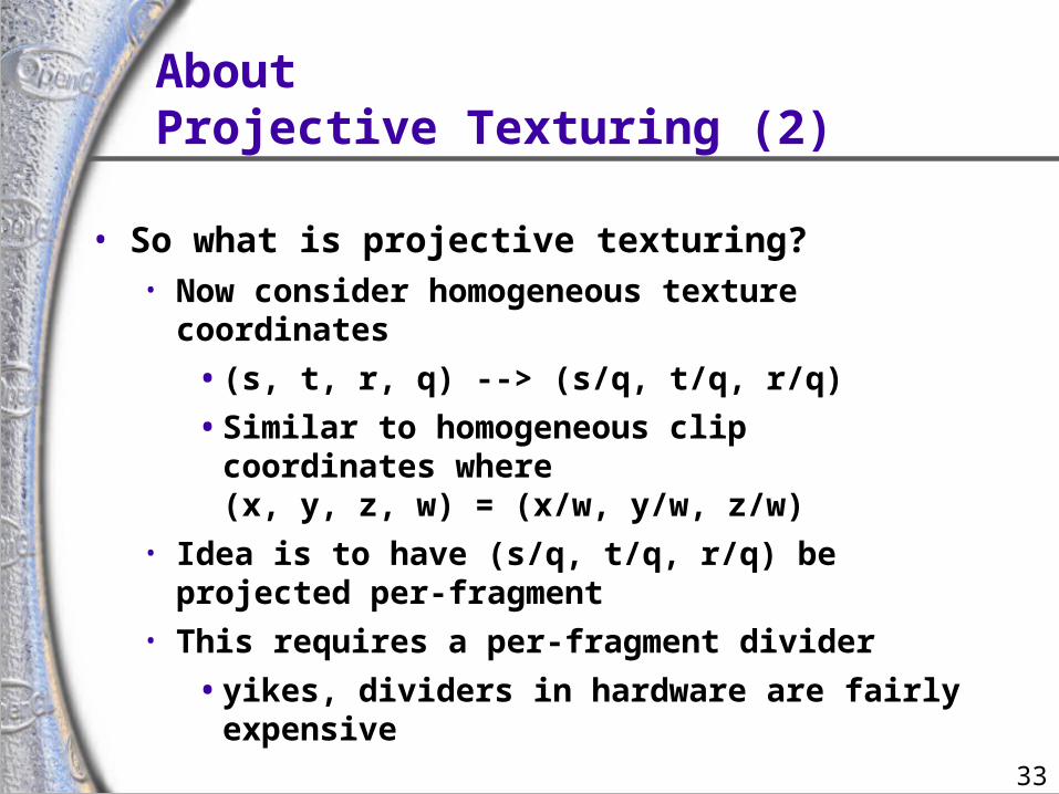
• So what is projective texturing?• Now consider homogeneous texture coordinates
• (s, t, r, q) --> (s/q, t/q, r/q)
• Similar to homogeneous clip coordinates where(x, y, z, w) = (x/w, y/w, z/w)
• Idea is to have (s/q, t/q, r/q) be projected per-fragment
• This requires a per-fragment divider
• yikes, dividers in hardware are fairly expensive
34
AboutProjective Texturing (3)
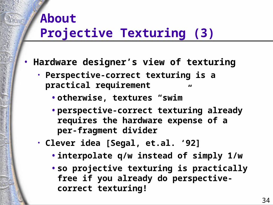
• Hardware designer’s view of texturing• Perspective-correct texturing is a practical
requirement
• otherwise, textures “swim”
• perspective-correct texturing already requires the hardware expense of a per-fragment divider
• Clever idea [Segal, et.al. ‘92]
• interpolate q/w instead of simply 1/w
• so projective texturing is practically free if you already do perspective-correct texturing!
35
AboutProjective Texturing (4)
• Tricking hardware into doing projective textures• By interpolating q/w, hardware computes per-
fragment
• (s/w) / (q/w) = s/q
• (t/w) / (q/w) = t/q• Net result: projective texturing
• OpenGL specifies projective texturing
• only overhead is multiplying 1/w by q
• but this is per-vertex
36
Back to the ShadowMapping Discussion . . .
• Assign light-space texture coordinates via texgen• Transform eye-space (x, y, z, w) coordinates to the light’s view frustum (match
how the light’s depth map is generated)• Further transform these coordinates to map directly into the light view’s depth
map• Expressible as a projective transform
• load this transform into the 4 eye linear plane equations for S, T, and Q coordinates
• (s/q, t/q) will map to light’s depth map texture
37
Shadow MapOperation
• Automatic depth map lookups• After the eye linear texgen with the proper transform
loaded
• (s/q, t/q) is the fragment’s corresponding location within the light’s depth texture
• r/q is the Z planar distance of the fragment relative to the light’s frustum, scaled and biased to [0,1] range
• Next compare texture value at (s/q, t/q) to value r/q
• if texture[s/q, t/q] r/q then not shadowed
• if texture[s/q, t/q] < r/q then shadowed
38
Dedicated HardwareShadow Mapping Support
• SGI RealityEngine, InfiniteReality, and GeForce3 Hardware• Performs the shadow test as a texture filtering
operation
• looks up texel at (s/q, t/q) in a 2D texture
• compares lookup value to r/q
• if texel is greater than or equal to r/q, then generate 1.0
• if texel is less than r/q, then generate 0.0• Modulate color with result
• zero if fragment is shadowed or unchanged color if not
39
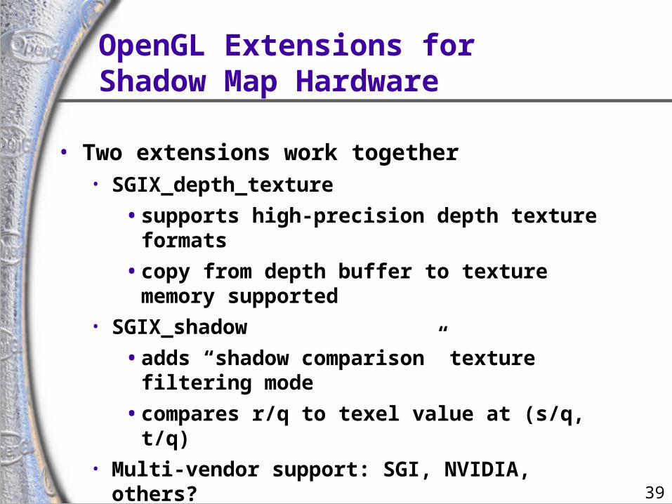
OpenGL Extensions forShadow Map Hardware
• Two extensions work together• SGIX_depth_texture
• supports high-precision depth texture formats
• copy from depth buffer to texture memory supported
• SGIX_shadow
• adds “shadow comparison” texture filtering mode
• compares r/q to texel value at (s/q, t/q)• Multi-vendor support: SGI, NVIDIA, others?
• Brian Paul has implemented these extensions in Mesa!
40
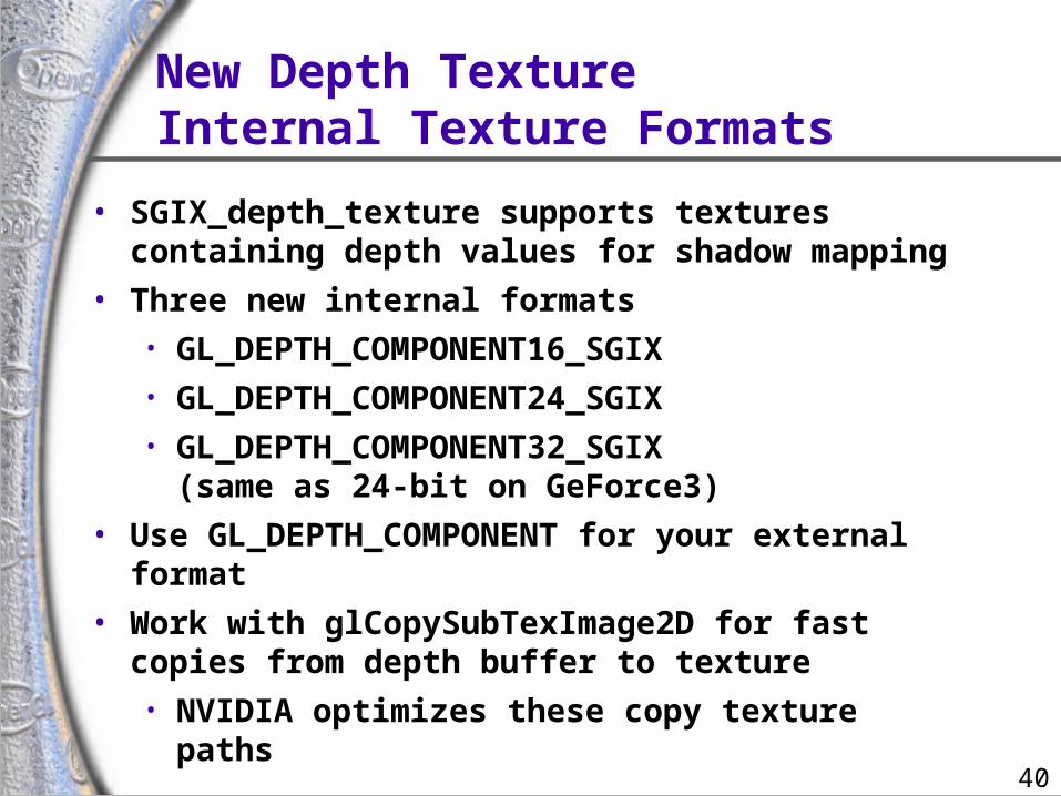
New Depth TextureInternal Texture Formats
• SGIX_depth_texture supports textures containing depth values for shadow mapping
• Three new internal formats• GL_DEPTH_COMPONENT16_SGIX• GL_DEPTH_COMPONENT24_SGIX• GL_DEPTH_COMPONENT32_SGIX
(same as 24-bit on GeForce3)
• Use GL_DEPTH_COMPONENT for your external format
• Work with glCopySubTexImage2D for fast copies from depth buffer to texture• NVIDIA optimizes these copy texture paths
41
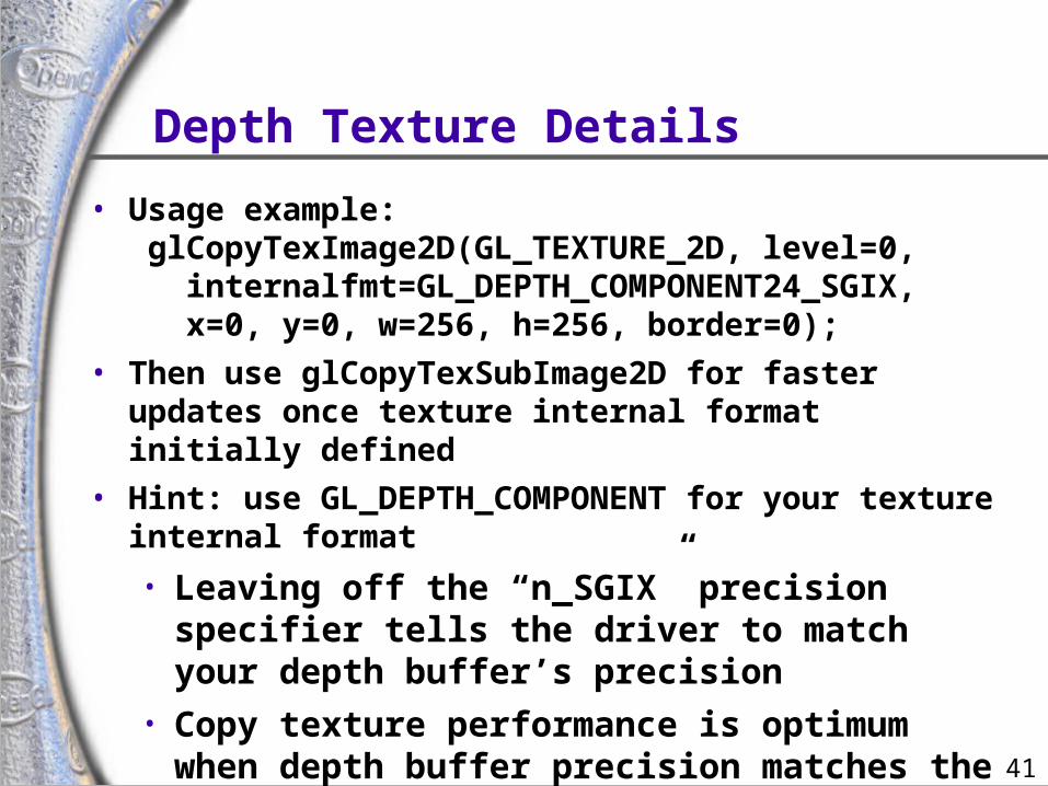
Depth Texture Details
• Usage example: glCopyTexImage2D(GL_TEXTURE_2D, level=0, internalfmt=GL_DEPTH_COMPONENT24_SGIX, x=0, y=0, w=256, h=256, border=0);
• Then use glCopyTexSubImage2D for faster updates once texture internal format initially defined
• Hint: use GL_DEPTH_COMPONENT for your texture internal format
• Leaving off the “n_SGIX” precision specifier tells the driver to match your depth buffer’s precision
• Copy texture performance is optimum when depth buffer precision matches the depth texture precision
42
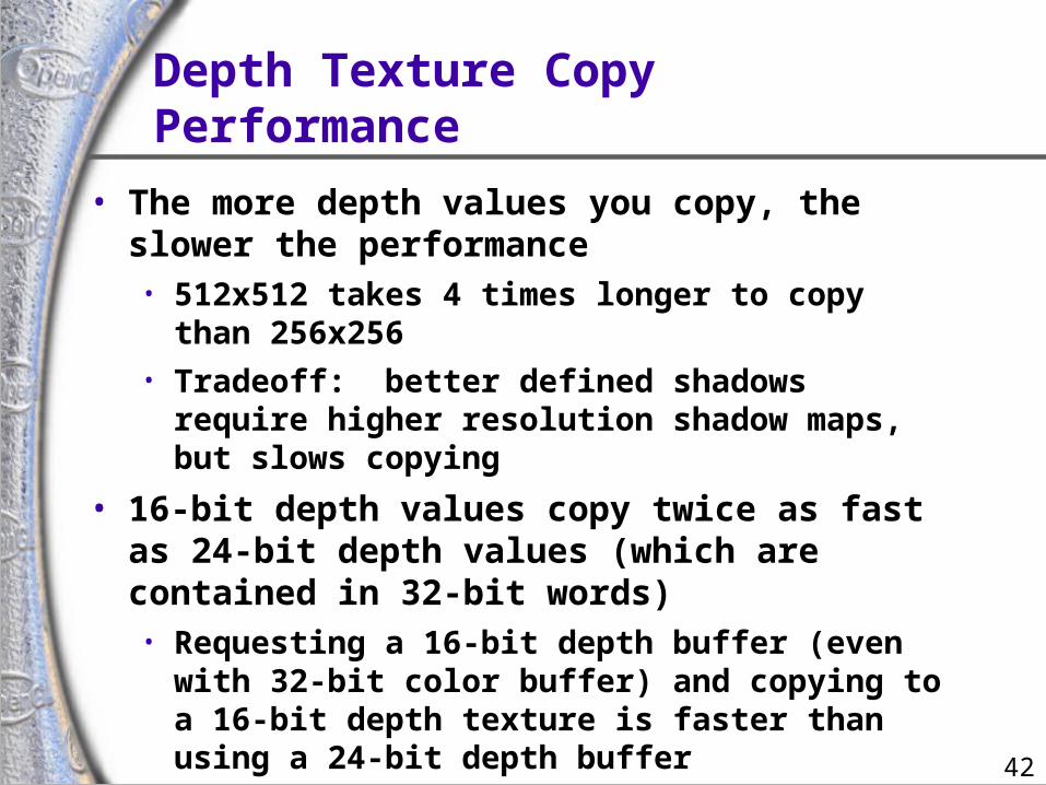
Depth Texture Copy Performance
• The more depth values you copy, the slower the performance• 512x512 takes 4 times longer to copy than 256x256• Tradeoff: better defined shadows require higher
resolution shadow maps, but slows copying
• 16-bit depth values copy twice as fast as 24-bit depth values (which are contained in 32-bit words)• Requesting a 16-bit depth buffer (even with 32-bit
color buffer) and copying to a 16-bit depth texture is faster than using a 24-bit depth buffer
• Note that using 16-bit depth buffer usuallyrequires giving up stencil
43
Hardware ShadowMap Filtering
• “Percentage Closer” filtering• Normal texture filtering just averages color
components• Averaging depth values does NOT work• Solution [Reeves, SIGGRAPH 87]
• Hardware performs comparison for each sample
• Then, averages results of comparisons• Provides anti-aliasing at shadow map edges
• Not soft shadows in the umbra/penumbra sense
44
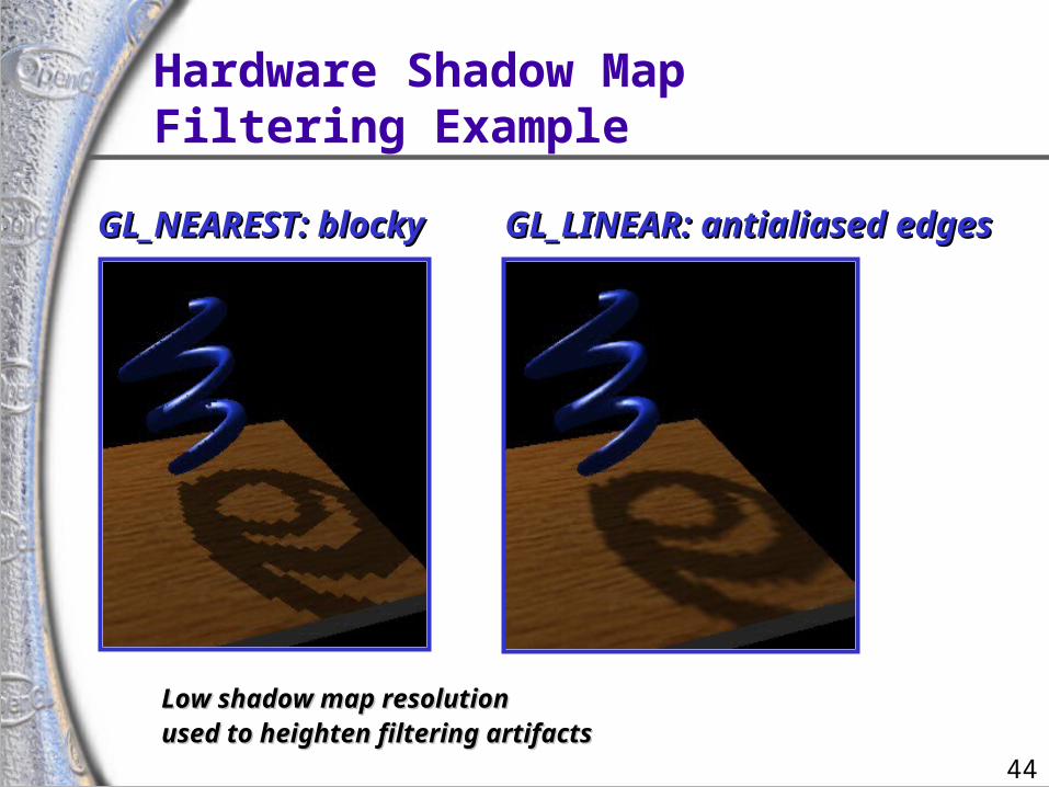
Hardware Shadow MapFiltering Example
GL_NEAREST: blockyGL_NEAREST: blocky GL_LINEAR: antialiased edgesGL_LINEAR: antialiased edges
Low shadow map resolutionLow shadow map resolutionused to heighten filtering artifactsused to heighten filtering artifacts
45
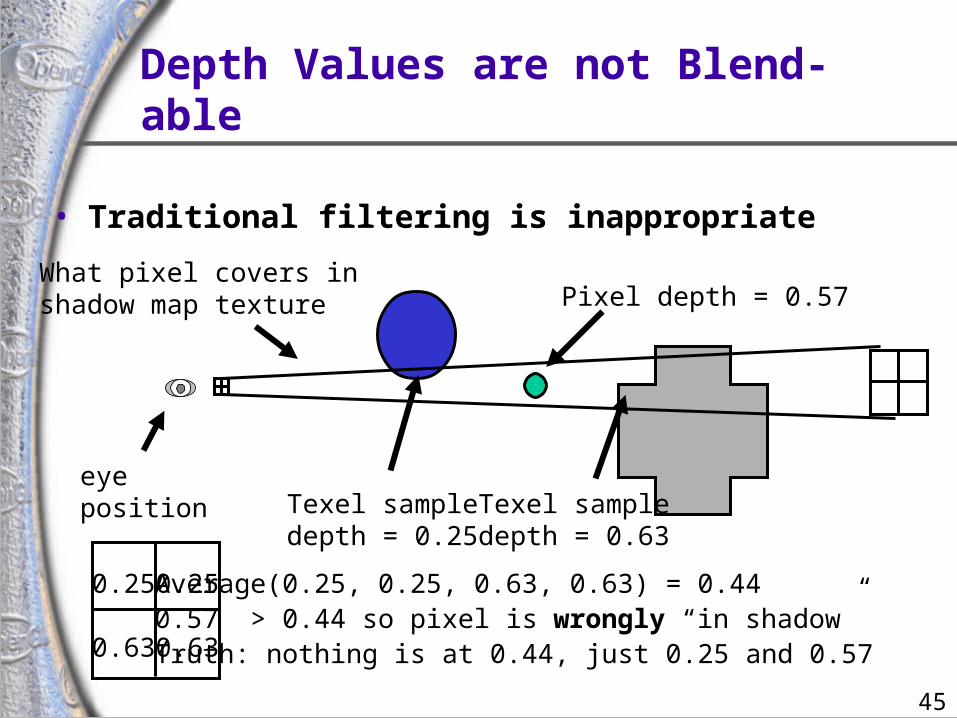
Depth Values are not Blend-able
• Traditional filtering is inappropriate
eyeposition
What pixel covers inshadow map texture
Texel sampledepth = 0.25
Texel sampledepth = 0.63
0.63
0.25 0.25
0.63
Average(0.25, 0.25, 0.63, 0.63) = 0.440.57 > 0.44 so pixel is wrongly “in shadow”Truth: nothing is at 0.44, just 0.25 and 0.57
Pixel depth = 0.57
46
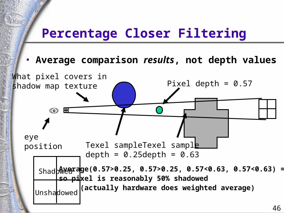
Percentage Closer Filtering
eyeposition
What pixel covers inshadow map texture
Texel sampledepth = 0.25
Texel sampledepth = 0.63
Shadowed Average(0.57>0.25, 0.57>0.25, 0.57<0.63, 0.57<0.63) = 50%so pixel is reasonably 50% shadowed (actually hardware does weighted average)
Pixel depth = 0.57
Unshadowed
• Average comparison results, not depth values
47
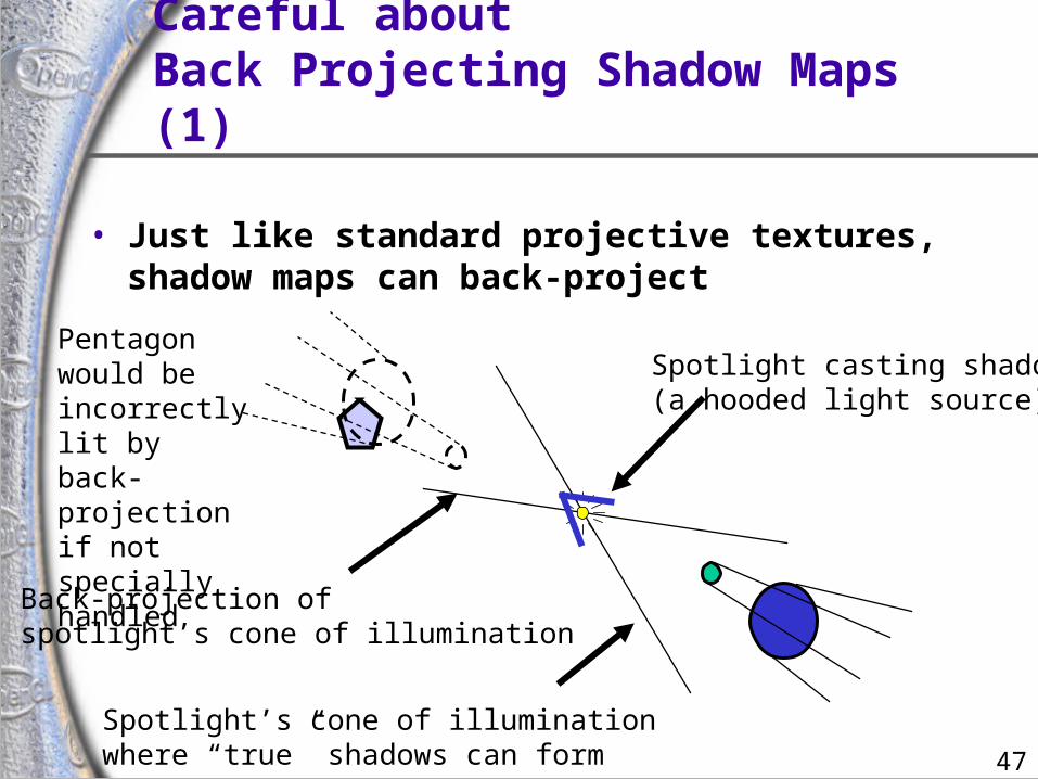
Careful aboutBack Projecting Shadow Maps (1)
• Just like standard projective textures, shadow maps can back-project
Spotlight casting shadows(a hooded light source)
Spotlight’s cone of illuminationwhere “true” shadows can form
Back-projection ofspotlight’s cone of illumination
Pentagon would be incorrectlylit by back-projectionif not specially handled
48
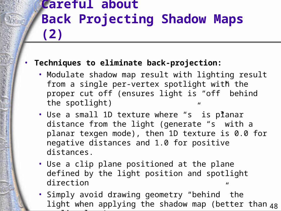
Careful aboutBack Projecting Shadow Maps (2)
• Techniques to eliminate back-projection:
• Modulate shadow map result with lighting result from a single per-vertex spotlight with the proper cut off (ensures light is “off” behind the spotlight)
• Use a small 1D texture where “s” is planar distance from the light (generate “s” with a planar texgen mode), then 1D texture is 0.0 for negative distances and 1.0 for positive distances.
• Use a clip plane positioned at the plane defined by the light position and spotlight direction
• Simply avoid drawing geometry “behind” the light when applying the shadow map (better than a clip plane)
• NV_texture_shader’s GL_PASS_THROUGH_NV mode
49
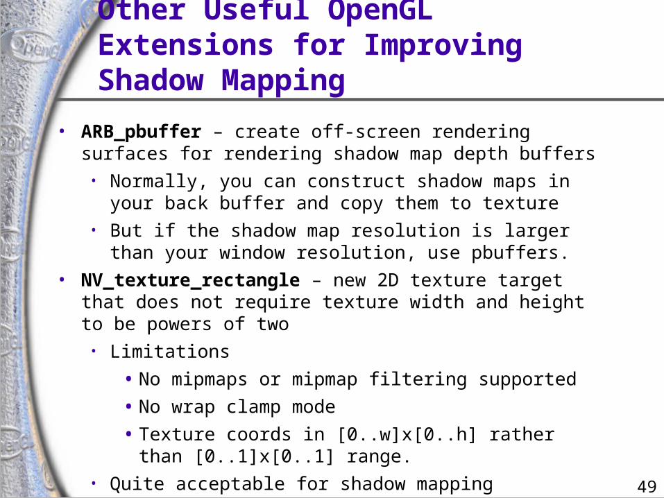
Other Useful OpenGL Extensions for Improving Shadow Mapping
• ARB_pbuffer – create off-screen rendering surfaces for rendering shadow map depth buffers
• Normally, you can construct shadow maps in your back buffer and copy them to texture
• But if the shadow map resolution is larger than your window resolution, use pbuffers.
• NV_texture_rectangle – new 2D texture target that does not require texture width and height to be powers of two
• Limitations
• No mipmaps or mipmap filtering supported
• No wrap clamp mode
• Texture coords in [0..w]x[0..h] rather than [0..1]x[0..1] range.
• Quite acceptable for shadow mapping
50
Combining Shadow Mappingwith other Techniques
• Good in combination with other techniques• Use stencil to tag pixels as inside or outside of
shadow• Use other rendering techniques in extra passes
• bump mapping
• texture decals, etc.• Shadow mapping can be integrated into more
complex multi-pass rendering algorithms
• Shadow mapping algorithm does not require access to vertex-level data• Easy to mix with vertex programs and such
51
Issues with ShadowMapping (1)
• Not without its problems• Prone to aliasing artifacts
• “percentage closer” filtering helps this
• normal color filtering does not work well• Depth bias is not completely foolproof• Requires extra shadow map rendering pass and
texture loading• Higher resolution shadow map reduces blockiness
• but also increases texture copying expense
52
Issues with ShadowMapping (2)
• Not without its problems• Shadows are limited to view frustums
• could use six view frustums for omni-directional light
• Objects outside or crossing the near and far clip planes are not properly accounted for by shadowing
• move near plane in as close as possible
• but too close throws away valuable depth map precision when using a projective frustum
53
Some Theory for Determining YourShadow Map Resolution (1)
• Requires knowing how pixels (samples) in the light’s view compare to the size of pixels (samples) in the eye’s view
• A re-sampling problem
• When light source frustum is reasonably well aligned with the eye’s view frustum, the ratio of sample sizes is close to 1.0
• Great match if eye and light frustum’s are nearly identical
• But that implies very few viewable shadows
• Consider a miner’s lamp (i.e., a light attached to your helmet)
• The chief reason for such a lamp is you don’t see shadows from the lamp while wearing it
54
Some Theory for Determining YourShadow Map Resolution (2)
• So best case is miner’s lamp
• Worst case is shadows from light shining at the viewer• “that deer in the headlights” problem – definitely
worst case for the deer• Also known as the “dueling frusta” problem
(frusta, plural of frustum)
• Let’s attempt to visualize what happens…
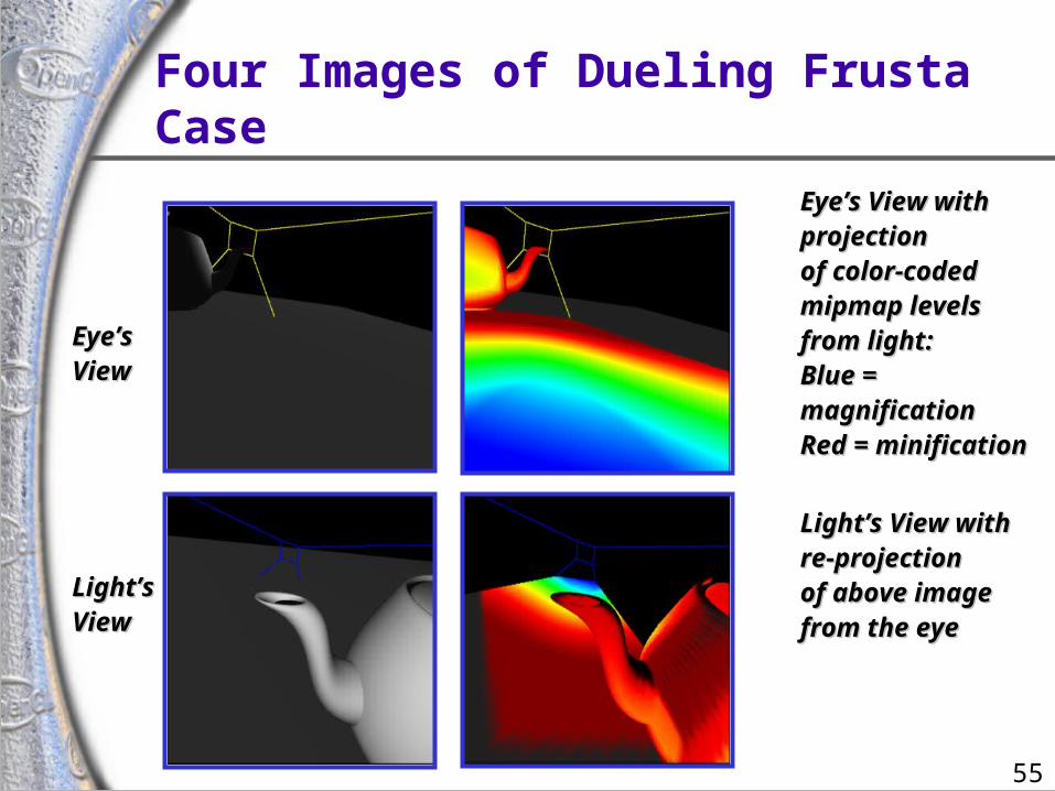
55
Four Images of Dueling Frusta Case
Eye’sEye’sViewView
Light’sLight’sViewView
Eye’s View with Eye’s View with projectionprojectionof color-codedof color-codedmipmap levelsmipmap levelsfrom light:from light:Blue = Blue = magnificationmagnificationRed = minificationRed = minification
Light’s View withLight’s View withre-projectionre-projectionof above imageof above imagefrom the eyefrom the eye
56
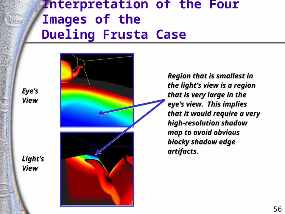
Interpretation of the Four Images of theDueling Frusta Case
Eye’sEye’sViewView
Light’sLight’sViewView
Region that is smallest in Region that is smallest in the light’s view is a region the light’s view is a region that is very large in the that is very large in the eye’s view. This implies eye’s view. This implies that it would require a very that it would require a very high-resolution shadow high-resolution shadow map to avoid obvious map to avoid obvious blocky shadow edge blocky shadow edge artifacts.artifacts.
57
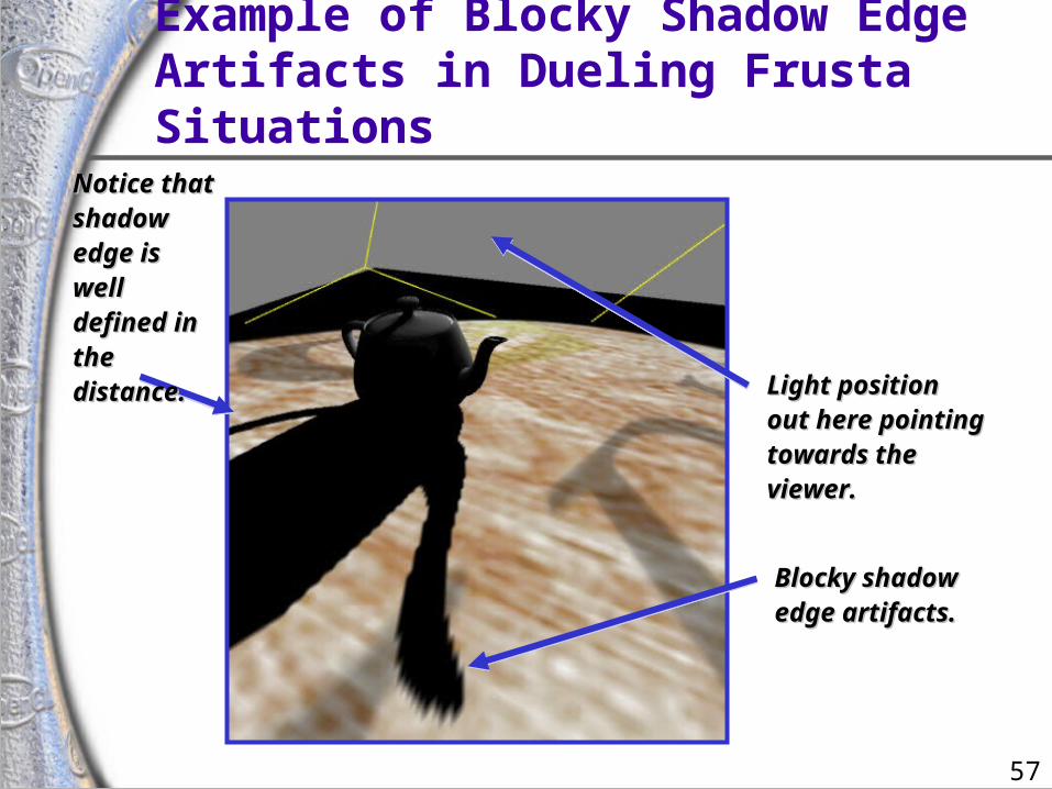
Example of Blocky Shadow EdgeArtifacts in Dueling Frusta Situations
Light position Light position out here pointing out here pointing towards the towards the viewer.viewer.
Blocky Blocky shadow edge shadow edge artifacts.artifacts.
Notice that Notice that shadow shadow edge is edge is well well defined in defined in the the distance.distance.
58
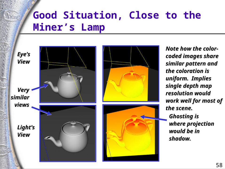
Good Situation, Close to the Miner’s Lamp
Eye’sEye’sViewView
Light’sLight’sViewView
Very Very similar similar viewsviews
Note how the color-Note how the color-coded images share coded images share similar pattern and similar pattern and the coloration is the coloration is uniform. Implies uniform. Implies single depth map single depth map resolution would resolution would work well for most of work well for most of the scene.the scene.
Ghosting is Ghosting is where projection where projection would be in would be in shadow.shadow.
59
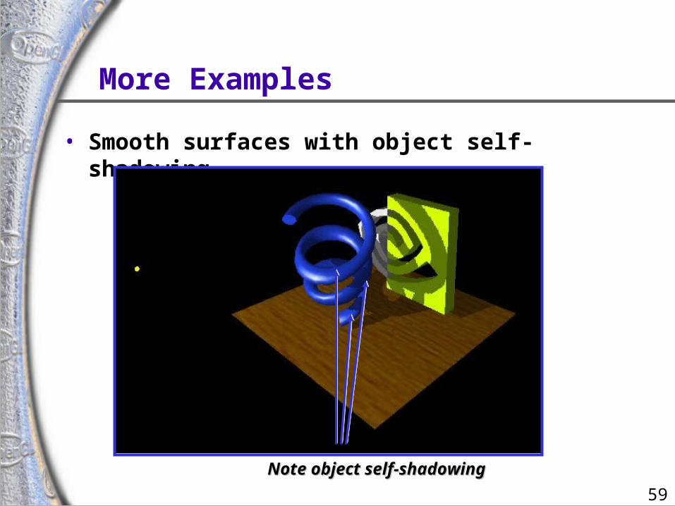
More Examples
• Smooth surfaces with object self-shadowing
Note object self-shadowingNote object self-shadowing
60
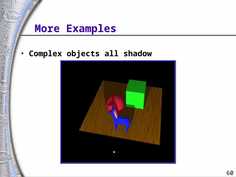
More Examples
• Complex objects all shadow
61
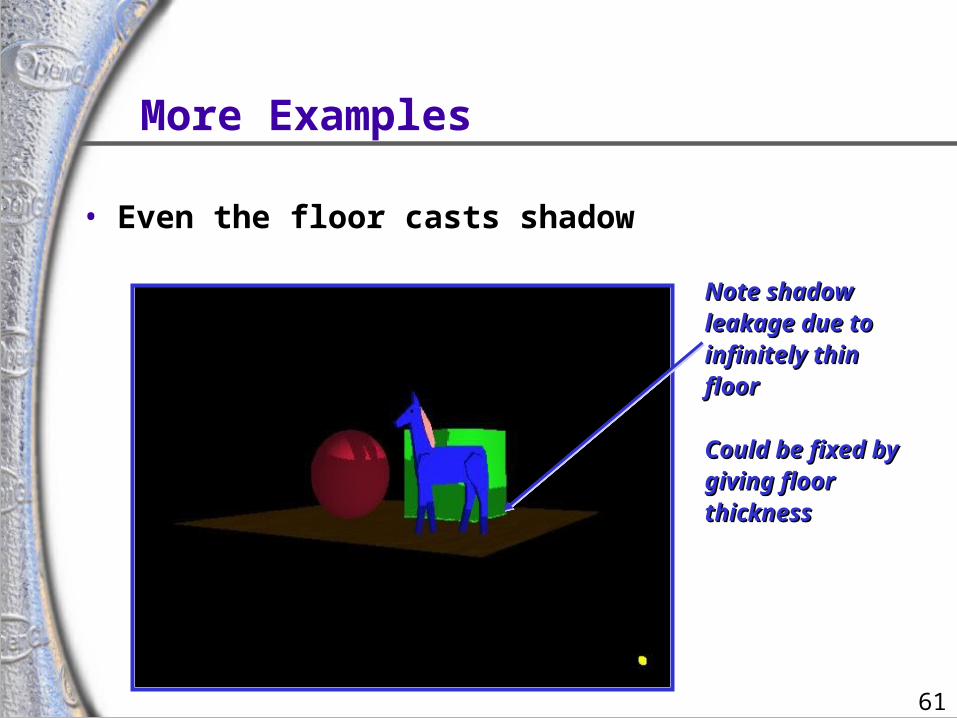
More Examples
• Even the floor casts shadow
Note shadow Note shadow leakage due toleakage due toinfinitely thin infinitely thin floorfloor
Could be fixed byCould be fixed bygiving floor giving floor thicknessthickness
62
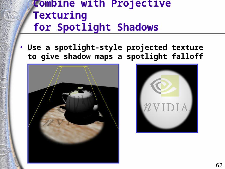
Combine with Projective Texturingfor Spotlight Shadows
• Use a spotlight-style projected texture to give shadow maps a spotlight falloff
63
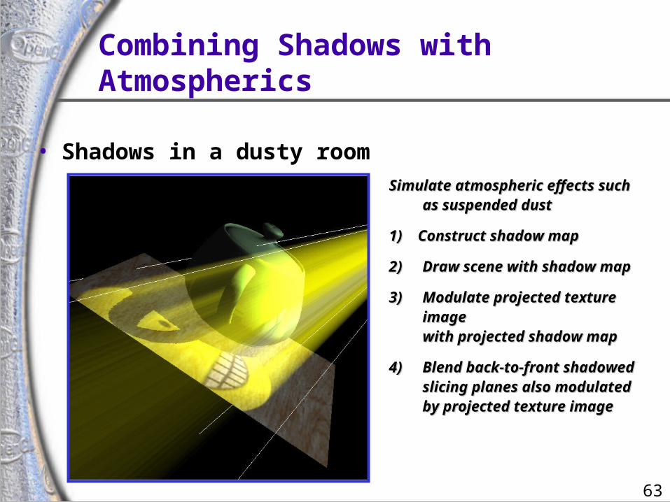
Simulate atmospheric effects suchSimulate atmospheric effects suchas suspended dustas suspended dust
1) Construct shadow map1) Construct shadow map
2)2) Draw scene with shadow mapDraw scene with shadow map
3)3) Modulate projected texture Modulate projected texture imageimagewith projected shadow mapwith projected shadow map
4)4) Blend back-to-front shadowedBlend back-to-front shadowedslicing planes also modulatedslicing planes also modulatedby projected texture imageby projected texture image
• Shadows in a dusty room
Combining Shadows withAtmospherics
64
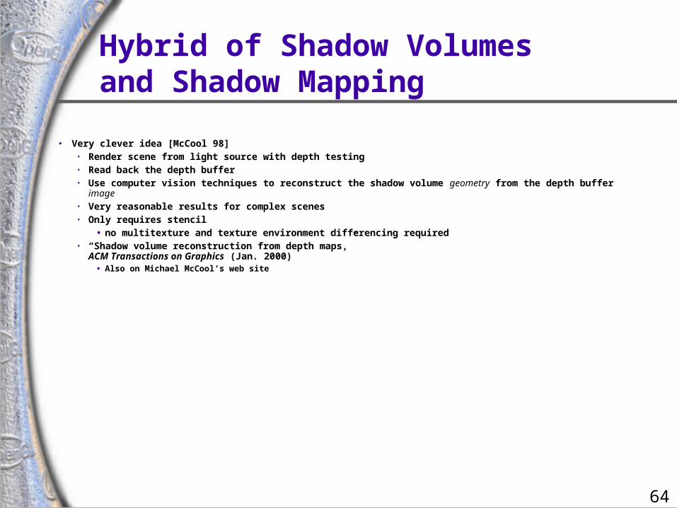
Hybrid of Shadow Volumesand Shadow Mapping
• Very clever idea [McCool 98]• Render scene from light source with depth testing• Read back the depth buffer• Use computer vision techniques to reconstruct the shadow volume geometry from the depth buffer image• Very reasonable results for complex scenes• Only requires stencil
• no multitexture and texture environment differencing required• “Shadow volume reconstruction from depth maps,”
ACM Transactions on Graphics (Jan. 2000)• Also on Michael McCool’s web site
65
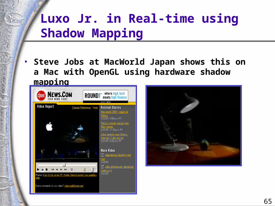
Luxo Jr. in Real-time usingShadow Mapping
• Steve Jobs at MacWorld Japan shows this on a Mac with OpenGL using hardware shadow mapping

66
• Luxo Jr. has two animated lights and one overhead light
• Three shadow maps dynamically generated per frame
• Complex geometry (cords and lamp arms) all correctly shadowed
• User controls the view,shadowing just works
• Real-time Luxo Jr.is technical triumphfor OpenGL
• Only available in OpenGL.
Luxo Jr. Demo Details
(Sorry, no demo. Images are from web cast video of Apple’s MacWorld Japan announcement.)
67
Shadow MappingSource Code
• Find it on the NVIDIA web site• The source code
• “shadowcast” in OpenGL example code
• Works on TNT, GeForce, Quadro, & GeForce3 using best available shadow mapping support
• And vendors that support EXT_texture_env_combine
• NVIDIA OpenGL Extension Specifications
• documents EXT_texture_env_combine, NV_register_combiners, SGIX_depth_texture, & SGIX_shadow
• http://www.nvidia.com
68
Conclusions
• Shadow mapping offers real-time shadowing effects• Independent of scene complexity• Very compatible with multi-texturing
• Does not mandate multi-pass as stenciled shadow volumes do
• Ideal for shadows from spotlights
• Consumer hardware shadow map support here today• GeForce3• Dual-texturing technique supports legacy hardware
• Same basic technique used by Pixar to generate shadows in their computer-generated movies