catalog fi01 2017 - industrial automation · siemens fi 01 · 2017 2/3 temperature measurement...
TRANSCRIPT

Siemens FI 01 · 2018
22/2 Product overview
SITRANS TS2/7 Technical description2/30 Detailed product overview2/36 Conversion assistance old appliance2/40 Ordering examples
SITRANS TS1002/41 Cable, mineral-insulated
SITRANS TS2002/44 Compact, mineral-insulated
SITRANS TS300For food, pharmaceuticals and biotechnology
2/47 - Modular design2/51 - Clamp-on design
SITRANS TS5002/55 Type 2, tubular version without
process connection2/60 Type 2N, tubular version,
with screw socket2/65 Type 2G, tubular version,
with screw socket and extension2/70 Type 2F, tubular version,
with flange and extension2/75 Type 3, tubular quick,
without process connection2/80 Type 3G, tubular quick,
with screw socket and extension2/85 Type 3F, tubular quick,
with flange and extension2/90 Type 4+4F barstock thermowell,
with extension2/94 For installation in existing protective
tubes
SITRANS TSinsert2/100 Measuring inserts for retrofits and
upgrades - European and American type
SITRANS TSthermowells2/104 Thermowells according to
DIN 437722/107 Thermowells according to
ASME B40.9
Resistance thermometers2/113 Temperature transmitters for mounting in
the connection head2/114 Flue gas resistance thermometers,
with connection head2/115 Resistance thermometers for
damp rooms2/116 Accessories – Welding-type protective
tubes, neck tubes and connection heads
Thermocouples2/118 Technical description
Straight thermocouples2/119 - to DIN 43733, with connection head2/120 - Individual parts and accessories
Transmitters in a compact design2/122 SITRANS TH100 Slim (Pt100)
Transmitters for mounting in sensor head
2/125 SITRANS TH100 (Pt100)2/129 SITRANS TH200 (Universal)2/136 SITRANS TH300 (Universal, HART)2/143 SITRANS TH320 (HART)2/152 SITRANS TH400 fieldbus transmitter2/158 SITRANS TH420 (HART)
Transmitters for rail mounting2/168 SITRANS TR200, two-wire system,
Universal2/175 SITRANS TR300, two-wire system,
Universal, HART2/182 SITRANS TR320, two-wire system, HART2/191 SITRANS TR420, two-wire system, HART2/201 SITRANS TW, four-wire system,
Universal, HART
Transmitters for field mounting2/213 SITRANS TF280 WirelessHART2/218 SITRANS TF two-wire system2/227 SITRANS TF fieldbus transmitter
Field indicator2/218 SITRANS TF Field indicator for 4 to 20 mA
Multipoint temperature transmitter 2/234 SITRANS TO500
Accessories2/237 Further accessories for assembly, con-
nection and transmitter configuration
You can download all instructions, catalogs and certificates for SITRANS T free of charge at the following Internet address: www.siemens.com/sitranst
Temperature Measurement
© Siemens AG 2018

2/2 Siemens FI 01 · 2018
Temperature MeasurementProduct overview
2
■ Overview
Type Description Page Software forparameterization
Temperature sensors
TS100 • Cable version• Universal use• For unfavorable space conditions• Mineral-insulated
2/41 -
TS200 • Compact version• Universal use• Mineral-insulated• For unfavorable space conditions
2/44 -
TS300 Resistance thermometer for food,pharmaceiticals and biotechnology
• Modular design, for installation in pipe-lines and tanks
2/47
• Clamp-on design, for attachment on the pipe primarily for sterilization processes
2/51
TS500, Type 2 • For the process industry(piping and tanks)
• Tubular thermowell for minimal to medium stress
• Thermowell as per DIN 43772, Type 2 without process connection
• Without extension, plug-in or use with moveable compression fittings
2/55 -
TS500, Type 2N • For the process industry (vessels and pipings)
• Tubular thermowell for minimal to medium stress
• Thermowell Type 2N similar to DIN 43772, screwed in
• Without extension, connection head not adjustable
2/60 -
TS500, Type 2G • For the process industry(vessels and pipings)
• Tubular version for minimal to medium stress
• Thermowell as per DIN 43722, Type 2G, screwed in
• With extension
2/65 -
TS500, Type 2F • For the process industry (vessels and pipings)
• Tubular version for minimal to medium stress
• Thermowell as per DIN 43722, Type 2F with flange
• With extension X
2/70 -
TS500, Type 3 • For the process industry (vessels and pipings)
• Tubular thermowell for minimal to medium stress
• Thermowell as per DIN 43722, Type 3 without process connection, improved re-sponse time
• Without extension, plug-in or use with moveable compression fittings
2/75 -
© Siemens AG 2018

2/3Siemens FI 01 · 2018
Temperature MeasurementProduct overview
2
TS500, Type 3G • For the process industry (vessels and pipings)
• Tubular version for minimal to medium stress
• Thermowell as per DIN 43722, Type 3G, screwed in, improved response time
• With extension X
2/80 -
TS500, Type 3F • For the process industry (vessels and pipings)
• Tubular thermowell for minimal to medium stress
• Thermowell as per DIN 43722, Type 3F with flange, improved response time
• With extension X
2/85 -
TS500, Type 4 • For the process industry (vessels and pipings)
• Barstock thermowell for medium to high-est stress
• Thermowell as per DIN 43722• Type 4 for weld-in• Type 4F with flange
2/90 -
TS500, Type 4F
TS500, installation • For the process industry (vessels and pipings)
• For the installation of existing thermowells• Suitable for thermowells as per
DIN 43772 as well as ASME B40.9-2001• With extension X
European type or American type
2/94 -
Measuring inserts for temperature sensors
European type • Replaceable• Mineral-insulated
2/100 -
American type 2/103 -
Thermowells for temperature sensors
Screw-in connection • Straight• Reduced• Tapered
2/104
Weld-in connection
Flange connection
Temperature sensors for combustion processes and damp rooms
Flue gas resistance thermometers
Largest measuring range:-50 ... +600 °C (-58 ... +1112 °F)
2/114
Resistance thermometers for damp rooms
Largest measuring range:-30 ... +60 °C (-22 ... +140 °F)
2/115
Straight thermocouples Largest measuring range:0 ... 1250 °C (32 ... 2282 °F)
2/119
Type Description Page Software forparameterization
© Siemens AG 2018

2/4 Siemens FI 01 · 2018
Temperature MeasurementProduct overview
2
Application Mounting of transmitter with Ex protection
Page Software for parameterization
Transmitter Sensor
Temperature transmitter in a compact design
SITRANS TH100 Slim For temperature measurement in combination with Pt100 compact resistance thermometers
- - 2/122 SIPROM T
Temperature transmitter for head mounting
SITRANS TH100Transmitters for Pt100
Zone 2,zone 1,zone 0,zone 21,zone 20,DIV 1,DIV 2
Zone 2,zone 1,zone 0,zone 21,zone 20,DIV 1,DIV 2
2/125 SIPROM T
SITRANS TH200Transmitters for connection to resistance thermometers, resis-tance-based sensors, thermocou-ples and DC voltages up to 1.1 V• Two-wire system• Universal
Zone 2,zone 1,zone 0,zone 21,zone 20,DIV 1,DIV 2
Zone 2,zone 1,zone 0,zone 21,zone 20,DIV 1,DIV 2
2/129 SIPROM T
SITRANS TH300Transmitters for connection to resistance thermometers, resis-tance-based sensors, thermocou-ples and DC voltages up to 1.1 V• Two-wire system• Universal• HART
Zone 2,zone 1,zone 0,zone 21,zone 20,DIV 1,DIV 2
Zone 2,zone 1,zone 0,zone 21,zone 20,DIV 1,DIV 2
2/136 SIMATIC PDM
SITRANS TH320 Transmitters with one input for connection to resistance ther-mometers, linear resistors, potenti-ometers, thermocouples and DC voltages up to 1.7 V• Two-wire system• HART 7• SIL2/3 according to IEC 61508
Zone 2,zone 1,zone 0,zone 21,zone 20,M1,DIV 1,DIV 2
Zone 2,zone 1,zone 0,zone 21,zone 20,M1,DIV 1,DIV 2
2/143 SIMATIC PDM
SITRANS TH400Transmitters for connection to resistance thermometers, resis-tance-based sensors, thermocou-ples and DC voltages• Fieldbus transmitters• PROFIBUS PA• FOUNDATION fieldbus
Zone 2,zone 1,zone 0,zone 21,zone 20,DIV 1,DIV 2
Zone 2,zone 1,zone 0,zone 21,zone 20,DIV 1,DIV 2
2/152 SIMATIC PDM for TH 400 with PROFIBUS PA
© Siemens AG 2018

2/5Siemens FI 01 · 2018
Temperature MeasurementProduct overview
2SITRANS TH420 Transmitters with two inputs for connection to resistance ther-mometers, linear resistors, potenti-ometers, thermocouples and DC voltages up to 1.7 V• Two-wire system• HART 7• SIL2/3 according to IEC 61508• High input availability
Zone 2,zone 1,zone 0,zone 21,zone 20,M1,DIV 1,DIV 2
Zone 2,zone 1,zone 0,zone 21,zone 20,M1,DIV 1,DIV 2
2/158 SIMATIC PDM
Temperature transmitters for rail mounting
SITRANS TR200• Two-wire system• Universal
Zone 2, zone 1, zone 0,zone 21
Zone 2, zone 1, zone 0, zone 21, zone 20
2/168 SIPROM T
SITRANS TR300• Two-wire system• Universal• HART
Zone 2, zone 1,zone 0,zone 21
Zone 2,zone 1, zone 0, zone 21,zone 20
2/175 SIMATIC PDM
SITRANS TR320 Transmitters with one input for connection to resistance ther-mometers, linear resistors, potenti-ometers, thermocouples and DC voltages up to 1.7 V• Two-wire system• HART 7• SIL2/3 according to IEC 61508
Zone 2,zone 1,zone 0,zone 21,zone 20,M1,DIV 1,DIV 2
Zone 2,zone 1,zone 0,zone 21,zone 20,M1,DIV 1,DIV 2
2/182 SIMATIC PDM
SITRANS TR420 Transmitters with two inputs for connection to resistance ther-mometers, linear resistors, potenti-ometers, thermocouples and DC voltages up to 1.7 V• Two-wire system• HART 7• SIL2/3 according to IEC 61508• High input availability
Zone 2,zone 1,zone 0,zone 21,zone 20,M1,DIV 1,DIV 2
Zone 2,zone 1,zone 0,zone 21,zone 20,M1,DIV 1,DIV 2
2/191 SIMATIC PDM
SITRANS TW• Four-wire system• Universal• HART
Safe area Zone 1, zone 0, zone 21,zone 20
2/201 SIMATIC PDM
Application Mounting of transmitter with Ex protection
Page Software for parameterization
Transmitter Sensor
© Siemens AG 2018

2/6 Siemens FI 01 · 2018
Temperature MeasurementProduct overview
2
■ Supplied product documentation on DVD and safety instructions
Temperature transmitters for field mounting
SITRANS TF280Transmitter for connection to resis-tance-based sensor• In field enclosure for heavy in-
dustrial use• battery-operated• WirelessHART
- - 2/213 Local operation via buttonsSIMATIC PDM local with HART modem and wireless via WirelessHART
SITRANS TFTransmitters for connection to resistance thermometers, resis-tance-based sensors, thermocou-ples and DC voltages up to 1.1 V• In field enclosure for heavy in-
dustrial use• HART, Universal
Zone 2,zone 1;zone 21,DIV 1,DIV 2
Zone 2, zone 1,zone 0
2/218 Depending on the installed TH200/TH300 transmitter
SITRANS TFFieldbus transmitters for connec-tion to resistance thermometers, resistance-based sensors, ther-mocouples and DC voltages up to 0.8 V• In field enclosure for heavy in-
dustrial use• PROFIBUS PA• FOUNDATION fieldbus
Zone 2,zone 1;zone 21,DIV 1,DIV 2
Zone 2zone 1,zone 0
2/227 SIMATIC PDM for PROFIBUS PA
Field indicator for 4 to 20 mA signals
SITRANS TFField indicator for4 to 20 mA signals Display of units can be user-defined
Zone 2,zone 1,zone 21,DIV 1,DIV 2
- 2/218 -
Multipoint temperature transmitter
SITRANS TO500 Multipoint temperature transmitter for measuring temperatures and temperature profiles using fiber optic Multipoint temperature measurement lances.
Zone 0, Zone 20
2/234 Via Ethernet with the supplied parameter assignment software
Application Mounting of transmitter with Ex protection
Page Software for parameterization
Transmitter Sensor
The scope of delivery of the Siemens products for process instrumentation includes a multilingual instruction sheet with safety instructions as well as a uniform mini DVD – Process Instrumentation and Weighing Systems.
This DVD contains the most important manuals and certificates for the Siemens process instrumentation and weighing technology portfolio. The delivery may also contain product-specific or order-specific printed materials.
For additional information, refer to the Annex on page 10/3.
© Siemens AG 2018

2/7Siemens FI 01 · 2018
Temperature MeasurementSITRANS TS
Technical description
2
■ Overview
Temperature sensors of the SITRANS TS product family are used to measure temperatures in industrial equipment.
Siemens offers the following temperature sensors:• SITRANS TS100
- General use- Compact design with connection cable
• SITRANS TS200 - General use- Compact design with plug/wire ends
• SITRANS TS300 - Use in food, pharmaceuticals and biotechnology- Modular or clamp-on design
• SITRANS TS500 - General use- Modular design with connection head and thermowell
■ Benefits
The modular design makes it possible to customize the tempera-ture sensor for most applications, while still being able to use many standardized individual components.
■ Application
Depending on the specification, sensors can be combined with different connection heads, neck tubes and process connec-tions. As a result, the sensors can be used in a large number of technical applications in the following industries:• Chemical industry• Petrochemical industry• Power engineering• Primary industry• Pharmaceutical industry• Biotechnology• Food manufacturing
SITRANS TS100 and SITRANS TS200
Temperature sensors of the SITRANS TS100 series are cable thermometers with different electrical connection options (e.g. plug, soldered connections, connection cables)
The SITRANS TS200 series of compact thermometers is charcterized by a compact design. Both temperature sensor se-ries are suitable for the following:• Measurements of temperatures of solids, where additional
thermowells are not required for replacements done during ongoing operations, e.g. bearing block temperature.
• Measurements which are particularly critical with regard to re-sponse times. The advantages offered by an additional ther-mowell are purposely omitted.
• Measuring points which must be easy to convert or relocate.• Surface temperature measurements: The temperature sensor
is used in conjunction with a surface connection piece.• Cost-effective transport: The mineral-insulated design allows
for economically feasible transport even at large lengths. From a length of 0.8 m (2.63 ft), the sensors can be delivered rolled up or bended.
SITRANS TS300 temperature sensors for food, pharmaceuti-cals and biotechnology
The temperature sensors of the SITRANS TS300 series are ther-mometers especially designed for measurements with high hy-gienic demands, such as in the food, pharmaceutical and bio-technology industries. The basic versions are:• Thermometers in modular design with replaceable measuring
insert and process connections usual in the industry• Clamp-on thermometers for measurement of the pipe surface
temperature without interrupting the process
SITRANS TS500 Temperature sensors as a module system
Due to their modular design, temperature sensors of the SITRANS TS500 series are well suited to a large number of ap-plications.
The replaceable measuring insert makes it possible to conduct maintenance work even during ongoing operations. These de-vices are used particularly frequently in vessels and pipelines of the following industries:• Power stations• Chemical industry• Petrochemical industry• General process engineering• Water, waste water
© Siemens AG 2018

2/8 Siemens FI 01 · 2018
Temperature MeasurementSITRANS TS
Technical description
2
■ Design
SITRANS TS100 7MC71xx
The following image illustrates the available designs for SITRANS TS100 temperature sensors:
SITRANS TS100
The following types of process connections can be imple-mented:• Compression fitting• Spring-loaded compression fitting• Soldering nipple• Direct soldering/welding in
SITRANS TS200 7MC72xx
The following image illustrates the available designs for SITRANS TS200 temperature sensors:
SITRANS TS 200, dimensions in mm (inch)
The following types of process connections can be imple-mented:• Compression fitting• Spring-loaded compression fitting• Soldering nipple• Direct soldering/welding in
SITRANS TS100, mineral-insulated (MIC)IP54 at the transition sensor/cable, plug see table
Version Degree of protection
Flying leads IP00
LEMO coupling 1S IP50
M12 device plugs IP54
Thermocouple coupling IP20
Basic sensorFlying leads
Thermocouple coupling
LEMO coupling 1S
M12 device plugs
Mini connection head
Head heightMeasuring insert length
Insertion length
IP levelsensor
IP levelterminals
0
1
2
3
4
5
0
5432
11
2345
U = BU = B + 10 (0.39)U = B - 10 (0.39)
U = B - 10 (0.39) IP65U = B - 5 (0.20)U = B - 20 (0.79)
0
HB
U
U = B IP65U = B + 10 (0.39) IP65U = B - 10 (0.39) IP65
U = B - 5 (0.20) IP65IP65
IP54
IP00IP00IP50
IP65IP65
HB
U
U
B
15(1.59)
B
U150
(5.91)10
(0.39)
B
U50
(1.97)5
(0.20)
B
U40
(1.57)
U36
(1.41)
U 65 (2.56)
B
10(0.39)
10(0.39)
B
20(0.79)
© Siemens AG 2018

2/9Siemens FI 01 · 2018
Temperature MeasurementSITRANS TS
Technical description
2
SITRANS TS300
SITRANS TS300 modular design
The following figure shows the available versions and compo-nents of the SITRANS TS300 temperature sensors in modular design.
SITRANS TS modular design, dimensions in mm (inch)
SITRANS TS300 Clamp-on
Temperature measurement is carried out over a modified and quick-response Pt100 measuring element, which is positioned and insulated over a pipe collar made of heat-resistant plastic.
The measuring insert contains a special temperature sensor tip made of silver, which is pressed evenly onto the pipeline by means of a spring.
The compulsory guide of the replaceable measuring insert en-sures even pressure contact on the pipeline, which ensures a re-producible measuring result.
The pipe diameter of the measuring tube is required for correct device selection. For special sizes, you start by selecting the matching collar size and entering the required size in plain text. Space-saving designs are available (latch fastener version) for installation in a limited space (e.g., tube bundles).
For correct assignment after recalibration, the collar as well as the measuring insert are identified with serial number and pipe diameter. This information can also be engraved.
Cable glandM12x1.5 for cable Ø 3 ... 6.5 (0.12 ... 0.26)
Ød Measuring insert outer diameter (6 (0.24))ØD Process connection outer diameterØD3 Protective pipe inner diameterH Head height
B Measuring insert length
N Nominal lengthU Insertion lengthX Extension length
Ø 50.5(1.99)
H1 Type Axx = 41 (1.61)Type Bxx = 26 (1.02)
U
N
X
Ø d
B =
N +
H1
Ø 60 (2.36)
Ø D3
Ø D
H
H1
Design
Measuring insert • Special measuring insert made of stainless steel; hygienic de-sign
• Measuring element made of sil-ver, thermal decoupling through plastic insert
Measuring insert screwed into collar with spring load. Use heat-conductive-compound (see accessories) prior to mounting the device.
Pipe collar
• Material Temperature resistant high-per-formance plastic with integrated insulating system in the hygienic design
• Ambient temperature influence Approx. 0.2 %/10 K
12
3
45
6
7
8
9
1 Vibration-locking-screw2 Mounting screws3 Process pipeline4 Temperature sensor5 Thermal decoupling6 Spring load7 Electrical connection
M128 Replaceable measuring
insert9 Heat insulated pipe collar
© Siemens AG 2018

2/10 Siemens FI 01 · 2018
Temperature MeasurementSITRANS TS
Technical description
2
The following figure illustrates the available designs and components for SITRANS TS300 temperature sensors in clamp-on design:
SITRANS TS300 clamp-on design, device plug, field enclosure, cable gland, versions, dimensions in mm (inch)
Measuring transducer with device plug M12x1
Cable glandM16x1.5 for cable Ø4.5 ... 10 (0.18 ... 0.39)
Clamp-on, clamping band installationwith hose clampsfor pipelines ≥ Ø10 ... ca. 300 (0.39 ... ca.11.81)
Clamp-on,clamping block installationfor pipelines Ø4 ... 57 (0.16 ... 2.24)
Clamp-on,latch fastener installation for pipelinesØ4 ... 17.2 (0.16 ... 0.68)
Example Ø21 (4.76)
Pip
e ra
dius
Cable glandM12x1.5 for cable Ø3 ... 6.5 (0.12 ... 0.26)
Electrical connectioncan be rotated by ± 170 ˚
Device plugM12x1
Device plugM12x1
Field housing, screw cap Material stainless steel IP 67
~ 83
.5 (3
.70)
max
. 29
(1.4
1)11.5(0.45)
Latch fastener version
Standard version
Pipe diameter B C 6 ... 17.2 30 35 (0.24 ... 0.68) (1.18) (1.38) 18 ... 35 40 60 (0.71 ... 1.38) (1.57) (2.36) 38 ... 50.8 50 80 (1.50 ... 2.00) (1.97) (3.15)
Pipe diameter A B C H 4 ... 17.2 20 30 35 79 (0.16 ... 0.68) (0.79) (1.18) (1.38) (3.11) 18 ... 38 30 40 70 99 (0.71 ... 1.49) (1.18) (1.57) (2.76) (3.90) 38.1 ... 57 40 50 85 119 (1.50 ... 2.24) (1.57) (1.97) (3.35) (4.68)
94 (3
.70)
36 (1.42)
19(0.75)
37(1.46)
19(0.75)
23(0
.91)
20(0.79)
20(0.79)
3 (0
.12) 6 (0.24)
51 (2
.01)
C
C
A
A
B
B
B
B
Ø60 (2.36)
© Siemens AG 2018

2/11Siemens FI 01 · 2018
Temperature MeasurementSITRANS TS
Technical description
2
SITRANS TS500 7MC75xx
The following image illustrates the available designs for SITRANS TS500 temperature sensors:
SITRANS TS500 temperature sensors; the IP degree of protection de-pends on the connection head (see page 2/15)
The temperature sensors of the SITRANS TS500 series are avail-able in three different designs:
■ Function
A complete measuring point consists of a measuring insert which contains the basic sensors, the protective fitting and an optional measurement value processor (transmitter).
The basic sensors are:• Resistance thermometers:
Temperature measurement is based on the temperature de-pendency of the installed measuring resistor.
• Thermocouples:Temperature measurement is based on the Seebeck effect. A thermocouple which subjected to a temperature drop pro-duces thermoelectric voltage that can be measured.
Transmitters:
The optional Siemens transmitters assume the following func-tions:• Optimum measurement processing• Strengthening of weak sensor signals directly on site• Transmits standardized signals• Protects against electromagnetic interfrences• Support enhanced diagnosis options
The resistance thermometer is intended for installation in con-tainers and pipelines for hygienic requirements.• Modular design consisting of protective pipe, measuring in-
sert, connection head and optional transmitter for replace-ment during operation.
• Hygienic version, design according to recommendations of the EHEDG
• Transmitter can be integrated (4 to 20 mA, PROFIBUS PA or FOUNDATION Fieldbus)
21 3
1 SITRANS TS500, tubular thermowell 2 SITRANS TS500, tubular thermowell3 SITRANS TS500, for installation in an existing thermowell
Version Description Application Process connection
1 • Tubular thermo-well
• Tubular thermo-well and exten-sion made of one pipe; closed at the tip with a welded bottom cap
Minimal to medium process load
• Welded connec-tion with thread or flange
• connection with compression fit-ting
2 • Barstock ther-mowell
• Barstock ther-mowell, tubular extension, exten-sion screwed into thermowell
Medium to highest process load
• Directly welded into pipeline
• With welded flange
• With male thread
3 • For installation into existing ther-mowells.
• Tubular extension
Process load depends on ther-mowell design
Screwed into exist-ing thermowell
© Siemens AG 2018

2/12 Siemens FI 01 · 2018
Temperature MeasurementSITRANS TS
Technical description
2
■ Configuration
Components: Process connections
This catalog is limited to the standard versions. Special versions are available on request. The technical data is designed to assist the user. It is the responsibility of the ordering party to make the correct selection of suitable devices.
Welding
A welded thermowell provides a permanent, secure and highly resilient process connection. This advantage requires an ade-quate weld-in quality.
It is not possible to accidentally open the process conneciton. Additional gaskets are not required. If the tube is not thick enough to ensure a secure welding connection, the appropriate weldable sockets are used. With weldable sockets of matching length it is also possible to largely stadardize a plant’s measur-ing points. Stocks of spare parts can therefore be reduced to a minimum
Weldable sockets
Thread
Type of installation: Welded threads
Welded threads of different thread types and sizes are firmly welded to the thermowell.
Welded threads
Type of installation: Compression fittings
Compression fittings are available as accessories. They fit with the diameter of the thermowell and provide for flexible installa-tion. The mounting length can be selected on site. When in-stalled correctly, compression fittings are well suited for low and medium pressure.
The difference between a normal and spring-loaded design is as follows:
In the case of spring-loaded compression fitting, the sensor is pressed against the measured object or the tip of the thermo-well, thus achieving outstanding heat contact.
Compression fitting
Spring-loaded compression fitting
Thread form
Cylindrical thread
Cylindrical threads do not seal in the thread but due to an addi-tional sealing face or seal. For example, threads with the short form "G" (as per ISO 228) feature a threat type with a defined screw gauge.
Cylindrical thread
Tapered thread
By contrast, tapered threads, such as the American "NPT" thread, seal metallically in the thread. The relevant length infor-mation in the catalog refers to the "fully-tightened point (hand-tight)" of the thread, which cannot be defined exactly due to standard-related tolerances. However, the spring unit of the measuring insert compensates for the differences in length.
NPT thread
X = extension lengthU = installation lengthE1 = neck tube / process connectionK1 = penetration depthK2 = length of the process connection
Thread form E / E1 K1 K2
Thermowell shape 2G + 3G
Cylindrical G 1/2" 15 27
G 1" 30 46
Tapered NPT 1/2" 9 30
Extensions7MC7500
Cylindrical M14 x 1.5 12 23
M18 x 1.5 12 25
G 1/2" 12 27
Tapered NPT 1/2" 9 33
K1
K2
E
XU
XUK1
K2
E
© Siemens AG 2018

2/13Siemens FI 01 · 2018
Temperature MeasurementSITRANS TS
Technical description
2
Flanges
The different properties of the flanges are as follows:• Standard series EN 1092, ASME 16.5,..• Nominal pressure• Nominal diameter• Sealing face
This information is stamped into the flange, as well as the mate-rial code and batch number for "3.1 Material". For flange ther-mowells made of expensive materials, wetted parts of the ther-mowell and the so-called flanged wheel are designed with the required material. The flanged wheel is welded in front of the flange sealing surface in this case. Non-wetted parts are listed in 316L.
Industry-specific process connections
Special process connections have become popular in different industries. For example, hygiene technology: clamp connec-tions, milk pipe unions and others.
Components: Thermowell
Thermowells fulfill two basic functions:• They protect the measuring insert from aggressive media• They make it possible to replace units during ongoing opera-
tions
This catalog is limited to the standard versions. Special versions are available on request. The large number of available types can be classified as follows:• Tubular thermowells
Tubular thermowells are also described as "welded" or "multi-part" thermowells (not to be confused with "multi-part protec-tive armatures"). They are suitable for low to medium process loads and can be manufactured on a cost-effective basis. Versions : - Form 2N similar to DIN 43772
with straight tip and shortest possible extension lengthnot adjustable connection head
- Form 2 as per DIN 43772with straight tip and extensionadjustable connection head
- Form 2: with process connectionForm 2G: Threaded connectionForm 2F: Flange connection
- Form 3 as per DIN 43772Design with tapered tip and extensionadjustable connection headFor these thermowells, thermowell tip is tapered by rotary swaging. This results in an excellent fit with the measuring in-sert and very good response times. Analogous to forms 2, versions 3/3G/3F are also available for form 3
• Barstock thermowells according to DIN 43772Where process loads are too high, or where thermowells with welded seams are not allowed, deep hole drilled barstock thermowells are used. Form 4 thermowells (as per DIN 43772) are very popular in this area. This thermowell type replaces the D1-D5 types of the predecessor standard DIN 43763:
The following table shows the dimensions of the different ther-mowells.
Sizing of thermowells
Thermowells made of barstock according to ASME B40.9
Thermowells according to ASME are distinguished by their form: Straight, reduced (staggered) or tapered along the entire instal-lation length.
Coarse subdivisions can also be made in the type of process connection: for screwing in, for welding, with flange or with the so-called Van Stone connection.
For the Van Stone connection, a small flange sealing surface ex-ists directly at the thermowell in barstock. This prevents any welding seams in the area touching the media. The thermowell is fixed by a collar flange that presses the sealing surface against the plant-side flange. Another advantage of this design is the optimized spare parts inventory. A thermowell fits onto multiple connecting flanges; the only difference is in the collar flanges.
Components: Extension (neck tube)
The extension is the section from the lower edge of the connec-tion head to the fixed point of the process connection or ther-mowell. There is a variety of terms for this components, e.g. neck tube. For this reason the term extension has been selected as a standardized term for the different designs. Function is the de-ciding factor:• Thermal decoupling of connection head from process tem-
perature see image page 2/20• Installation of connection head over existing insulation• Simple standardization of measuring inserts: In general, the
length of the extension may be freely selected. However, when using standardized insertion lengths, the option "Extension as per DIN 43 772" is recommended. This ensures that measur-ing inserts which are quickly available can be used. In case of special lengths, it is possible to standardize the measuring in-sert length through a clever combination with the respective special extension length. This allows customers to optimize their costs in purchasing and logistics.
• In the case of American-designed sensors, the extension also takes the spring load of the measuring unit.
• Depending on the design, the extension can also be used to achieve an alignment of the connection head.
• The form of the extension depends on the form of the ther-mowell:
DIN 43763 designinvalid
DIN 43772 design 4current
L in mm U in mm
D1 140 65
D2 200 125
D4 200 65
D5 260 125
Tip Process connection
Ø Inner [mm (inch)]
Ø Outer [mm (inch)]
Ø Inner [mm (inch)]
Ø Outer [mm (inch)]
Thermowell type, design
D1 D2 D3 D4
2N/2/2G/2F, tubular
7 (0.28) 9 (0.35) 7 (0.28) 9 (0.35)
2/2G/2F, tubular 7 (0.28) 12 (0.47) 7 (0.28) 12 (0.47)
3/3G/3F, tubular 6 (0.24 )tolerance acc. to DIN 43772
9 (0.35) 7 (0.28) 12 (0.47)
4/4F, barstock 7 (0.28) 12,5 (0.49) 7 (0.28) 24 (0.94)
4/4F, fast response, bar-stock
3.5 (0.14) 9 (0.35) 3.5 (0.14) 18 (0.71)
D4 D1 D2D3
© Siemens AG 2018

2/14 Siemens FI 01 · 2018
Temperature MeasurementSITRANS TS
Technical description
2
- Tubular thermowellThe extension and thermowell usually consist of one contin-uous tube. The process connection is welded on. (= one-piece protective armature).
- Barstock thermowellsExtension and thermowell of two components which are welded together. The process connection is attached to the thermowell (= multi-piece protective armature).
Extensions as per DIN 43772
Versions
With regard to their function, extensions can be classified into two types:• Adjustable/not adjustable:
Function on the neck tube to align the connection head to the desired direction
• Integrated measuring insert spring load:In the case of American-type sensors, the spring load of the measuring insert is integrated into the extension. Measuring insert and extension form one unit.
Versions: particularly with heavy stainless steel connection heads in com-bination with vibration, a short extension length should be selected or ex-ternal support should be provided.
Thermowell type X [mm (inch)] M [mm (inch)] Divisible
2G 129 (5.08) 145 (5.71) No
2F 64 (2.52) 80 (3.15) No
3G 131 (5.19) 147 (5.79) No
3F 66 (2.60) 82 (3.23) No
4 (only L=110) 139 (5.47) 155 (6.10) Yes
4 (others) 149 (5.87) 165 (6.50) Yes
X
M
European typeadjustable, cylindrical
European typeadjustable, tapered
wihtout extensionwihtout thread(optional gland)
European typenot adjustable, cylindrical
European typenot adjustable, tapered
European typenot adjustable, nipple
European typeadjustablenipple-union-nipple
American typeadjustable, nipple-union-nipple spring load
American typenot adjustablenipple-union-nipplespring load
© Siemens AG 2018

2/15Siemens FI 01 · 2018
Temperature MeasurementSITRANS TS
Technical description
2
Components: Connection head
Connection head
The connection head protects the connection department.
The connection head features sufficient room for mounting a clamping base or transmitter.
Different connection heads are used depending on the applica-tion and preference:
Connection head TypeMaterial
Designation Cable gland Degree of protection
Transmitter installation
Connection height H1 [mm (inch)]
Explosion protection optional
BA0Aluminum
Flange lid M20 x 1,5brass
IP65 Measuring insert
26 (1.02) Ex i
BB0Aluminum
Hinged cover low
M20 x 1,5brass
IP65 Measuring insert
26 (1.02) Ex i
BC0AluminumBP0Plastic
Hinged cover high
M20 x 1,5 BC0: brassBP0: polyamide
IP65 Measuring insert and/or hinged cover (tandard)
26 (1.02) Ex i
BM0Plastic
Screw cover M20 x 1,5polyamide
IP54 Measuring insert
26 (1.02) Ex i
BS0Stainless steel
Screw cover M12 x 1,5polyamide
IP67 Measuring insert
26 (1.02) Ex i
AG0AluminumAU0Stainless steelAISI 316 (1.4401)
Screw cover, heavy-duty
M20 x 1,5 not Ex: plasticEx i/Ex n: brassEx d: without cable gland
IP66/68 (IP68: 1.5 m; 2 h)
Measuring insert
41 (1.61) Ex i, Ex d
AH0AluminumAV0Stainless steelAISI 316 (1.4401)
Screw cover, sight glass, heavy-duty, with 4 ... 20 mA display
M20 x 1,5not Ex: plasticEx i/Ex n: brassEx d: without cable gland
IP66/68 (IP68: 1.5 m; 2 h)
Measuring insert
41 (1.61) Ex i, Ex d
H1
H1
H1
H1
H1
H1
H1
© Siemens AG 2018

2/16 Siemens FI 01 · 2018
Temperature MeasurementSITRANS TS
Technical description
2
Components: Measuring insert
Measuring insert
The measuring insert of the temperature sensor is built into the protective armature (thermowell, extension and connection head). The sensor element is protected in the measuring insert. The spring load of the Siemens measuring inserts provide good thermal contact with the bottom of the thermowell, and vibration resistance is significantly increased. Only highly resistant min-eral-insulated cables (so-called MIC) are used for the electrical connection between the sensor element and connection head. The highly compacted insulation of magnesium oxide achieves excellent level of vibration resistance. The following measuring insert designs are the most widely used on the world market:
European type American type
European type
European type measuring inserts can be replaced without hav-ing to dismantle the connection head. The springs are located either on the transmitter or the terminal block. This makes it pos-sible to achieve a 8 to 10 mm spring range. If no transmitter is mounted, there is a ceramic base in its place. However, with the order option G01, a version with free wire ends instead of a ce-ramic base can be selected for mounting head-mounted trans-mitters.
American type
American-type measuring inserts feature a large spring range. These measuring inserts are ideal for use with NPT threads with the typical loose tolerances. In this configuration, the extension function is partially or fully integrated (nipple-union-nipple). Moreover it is also possible to directly attach field devices, e.g. SITRANS TF.
Components: Transmitters
SITRANS TH head transmitters process the weak non-linear sen-sor signals and transmit a stable and temperature-linear stan-dard signal, thereby minimizing sensor signal disruptions.
The transmitters permanently monitor the temperature sensors and transmit diagnostic data to superordinate systems.
Because of the low energy feed of the SITRANS TH head trans-mitters, self-heating of the temperature sensors can be main-tained at minimal levels.
The electrical isolation and integrated cold junction ensure that temperature sensors with thermocouples provide reliable mea-surements at a low cost.
SITRANS TH product family
For detailed technical data on the SITRANS TH transmitters, please refer to the catalog FI 01.• TH100 - the basic device
- Output 4 to 20mA- for Pt100- can be configured using simple software
• TH200 - the universal device - Output 4 to 20mA- Resistance thermometer, thermocouples- can be configured using simple software
• TH300 - HART universal - Output 4 to 20 mA/HART- Resistance thermometer, thermocouples- HART conforming- Diagnostic functions
• TH400 - Fieldbus PA and FF - Output PROFIBUS PA or FOUNDATION Fieldbus- Resistance thermometer, thermocouples- Diagnostic functions; for detailed technical description of the
SITRANS TH transmitter please refer to the related chapter of this catalog.
Installation types
All SITRANS TH transmitters can be installed in type B connec-tion heads. The following installation forms are used:• Measuring insert installation
Our standard version offers the following advantages - Small vibrating masses and compact design- Insert-transmitter unit can be replaced quickly
Installation of measuring insert
• Hinged cover installation - Standard for head type BC0 and BP0- Advantage: Measuring insert and transmitter can be re-
paired/maintained separately (recalibration).
Hinged cover installation
© Siemens AG 2018

2/17Siemens FI 01 · 2018
Temperature MeasurementSITRANS TS
Technical description
2
Measuring technology: Sensor elements
The diverse application spectrum for industrial temperature measuring technology requires different sensor technologies.
Resistance thermometer
Sensor elements made of other basic materials with different nominal resistances or different underlying standards are avail-able on request. Resistance thermometers can be classified as follows:• Basic design:
The sensor element is built with thin layer technology. The resistance material is applied in the form of a thin layer on a ceramic carrier material.
• Versions featuring increased vibration-resistance:In addition to the basic design, the vibration resistance is improved through extra measures.
• Versions with expanded measuring range:Elements in wire-wound design. The wire winding is embed-ded in a ceramic body.
Thermocouples
Other thermocouples based on other thermo couples or under-lying standards are available upon request.
The most common base metal thermocouples include:• Type N (NiCrSi-NiSi) high degree of stability even in upper
temperature range.• Type K (NiCr-Ni) more stable than type J, but drifts in upper
range.• Type J (Fe-CuNi) narrow application band
Measuring technology: Measuring range
The measuring range describes the temperature limits within which the thermometer can be used in a way that is meaningful for measurement purposes. Depending on the loads present, the thermowell materials and the desired accuracy levels, the actual application range for the thermometer may be smaller.
Measuring technology: Measuring accuracy
Resistance thermometer
The tolerance classes of the resistance thermometers corre-spond with IEC 751/EN 60751:
The following tables provide an overview of the scope of these tolerances. If the specified limits are exceeded with a resistance thermometer, the values of the next lower accuracy class apply permanently:
1) The requirements of IEC 60751 are being observed. In case of high requirements regarding long-term stability, Pt100 sensors "expanded mea-suring range" should be used for temperatures above 350 °C (662 °F).
Thermocouples
The tolerance classes of the thermocouples correspond with IEC 584/EN 60584:
Catalog versions
Resistance thermometer [°C (°F)]
Basic version and increased vibration resistance
-50 ... +400 (-58 ... +752)
Expanded measuring range -196 ... +600 (-320.8 ... +1112)
Thermocouple [°C (°F)]
Type N -40 ... +1100 (-40 ... +2112)
Type K -40 ... +1000 (-40 ... +1132)
Type J -40 ... +750 (-40 ... +1382)
Tolerance ∆t
Basic accuracy, Class B (0.30 °C +0.0050|t[°C]|)(0.54 °F +0.0050|t [°F]-32|)
Increased accuracy, Class A (0.15 °C +0.0020|t[°C]|)(0.27 °F +0.0020|t [°F]-32|))
High degree of accuracy, Class AA (1/3 B)
(0.10 °C +0.0017|t[°C]|)(0.18 °F +0.0017|t [°F]-32|))
Resistance thermometerBasic version [°C (°F)]
Tolerance Range
Basic accuracy, Class B
-50 ... +400 (-58 ... +752)1)
Increased accuracy, Class A
-30 ... +300 (-22 ... +572)
High degree of accuracyClass AA (1/3 B)
0 ... 150 (32 ... 302)
Resistance thermometerIncreased vibration-resistance [°C (°F)]
Tolerance Range
Basic accuracy, Class B
-50 ... +400 (-58 ... +752)1)
Increased accuracy, Class A
-30 ... +300 (-22 ... +572)
High degree of accuracyClass AA (1/3 B)
0 ... 150 (32 ... 302)
Resistance thermometerExpanded measuring range [°C (°F)]
Tolerance Range
Basic accuracy, Class B
-196 ... +600 (-321 ... +1112)
Increased accuracy, Class A
-100 ... +450 (-148 ... +842)
High degree of accuracyClass AA
-50 ... +250 (-58 ... +482)
Type Basic accuracy, Class 2 Increased accuracy, Class 1
N -40 °C ... +333 °C2.5 °C (-40 °F ... +631 °F 4.5 °F)333 °C ... 1100 °C ±0.0075x|t[°C]| (631 °F ... 2012 °F ±0.0075x|t[°F]-32|)
-40 °C ... +375 °C1.5 °C (-40 °F ... +707 °F 2.7 °F)375 °C ... 1000 °C±0.004x|t[°C]| (707 °F ... 1832 °F ±0.004x|t[°F]-32|)
K -40 °C ... +333 °C2.5 °C (-40 °F ... +631 °F 4.5 °F)333 °C ... 1000 °C±0.0075x|t[°C]| (631 °F ... 1832 °F ±0.0075x|t[°F]-32|)
-40 °C ... +375 °C1.5 °C (-40 °F ... +707 °F 2.7 °F)375 °C ... 1000 °C ±0.004x|t[°C]| (707 °F ... 1832 °F±0.004x|t[°F]-32|)
J -40 °C ... +333 °C2.5 °C (-40 °F ... +631 °F 4.5 °F)333 °C ... 750 °C±0.0075x|t[°C]| (631 °F ... 1382 °F ±0.0075x|t[°F]-32|)
-40 °C ... +375 °C1.5 °C (-40 °F ... +707 °F 2.7 °F)375 °C ... 750 °C ±0.004x|t[°C]| (707 °F ... 1382 °F ±0.004x|t[°F]-32|)
© Siemens AG 2018

2/18 Siemens FI 01 · 2018
Temperature MeasurementSITRANS TS
Technical description
2
Other thermocouples, ignoble
Other thermocouples. noble
SITRANS TS300 Clamp-on
Measuring technology: Response times
Response time describes the speed of the measurement system in the case of a temperature change, and is typically indicated as T0.5 or T0.9. The values indicate the time in which a mea-sured value has increased to 50% or 90% of the actual tempera-ture increase.
The main variables which affect response time are as follows:• Ideal thermowell geometry includes:
- smallest possible material at the tip- use of conductive material
• Thermal connection of measuring insert to thermowell:Due to the optimized design of the Siemens inserts (small gap width, spring system), they feature very good response be-havior. Because of the good fit, additional contact materials are not usually required except in certain applications e.g. at-tachment of a surface sensor.
• Size of temperature increase• Medium and flow rate
Resistance thermometer
Typical values as per EN 60751 in water at 0.4m/s can be found in the following table.
Thermocouples
Typical values as per EN 60751 in water at 0.4m/s can be found in the following table.
Type Basic accuracy, Class 2 Increased accuracy, Class 1
T -40 °C ... 133 °C 1 °C (-40 °F ... +271 °F 1.8 °F)133 °C ... 350 °C±0.0075x|t[°C]| (271 °F ... 662 °F±0.0075x|t[°F]-32|)
-40 °C ... +125 °C 0.5 °C (-40 °F ... +257 °F 0.9 °F)125 °C ... 350 °C ±0.004x|t[°C]| (257 °F ... 662 °F ±0.004x|t[°F]-32|)
E -40 °C ... +333 °C2.5 °C (-40 °F ... +631 °F4.5 °F)333 °C ... 900 °C ±0.0075x|t[°C]| (631 °F ... 1652 °F ±0.0075x|t[°F]-32|)
-40 °C ... +375 °C 1.5 °C (-40 °F ... +707 °F 2.7 °F)375 °C ... 800 °C±0.004x|t[°C]| (707 °F ... 1472 °F±0.004x|t[°F]-32|)
Type Basic accuracy, Class 2 Increased accuracy. Class 1
R and S
0 °C ... 600 °C1.5 °C (32 °F ... 1112 °F2.7 °F)600 °C ... 1600 °C0.0025 x |t| (1112 °F ... 2912 °F0.0025 x |t|)
0 °C ... 1100 °C1 °C (32 °F ... 2012 °F1.8 °F)1100 °C ... 1600 °C[1 + 0.003 (t - 1100)] °C (2112 °F ... 2912 °F[1.8 + 0.003 (t - 212)] °F)
B 600 °C ... 1700 °C0.0025 x |t|(1112 °F ... 3092 °F0.0025 x |t|)
Measuring accuracy
Reference conditions
• Pipeline 13 x 1.5 mm (0.51 x 0.06 inch) made of stainless steel using using thermal paste
• Ambient temperature 20 °C (68 °F)
• Medium Water, 120 °C (248 °F)
• Flow speed 3 m/s (9.84 ft/s)
Measuring accuracy using thermal paste (The accuracy depends on the geometry of the pipeline, the medium and the ambi-ent conditions. TM = process temperature; TA = ambient temperature)
Process-optimized for steam sterilization
• Class A as per IEC 60751 -40 ... +150 °C (-40 ... 302 °F)(TA-TM) x 0.02
Thermowell form Diameter [mm (inch)]
T0.5 T0.9
None 6 (0.24) 6 15
Straight (2) 9 (0.35)12 (0.47)
3445
90143
Tapered (3) 12 (0.47) 15 31
Barstock (4)U/C = 65
24 (0.95) 40 100
Barstock (4)]U/C = 65
24 (0.95) 45 110
Thermowell form Diameter [mm (inch)]
T0.5 T0.9
None 6 (0.24) 2 4
Straight (2) 9 (0.35)12 (0.47)
2019
6366
Tapered (3) 12 (0.47) 7 22
Barstock (4)U/C = 65
24 (0.95) 22 73
Barstock (4)]U/C = 65
24 (0.95) 20 53
© Siemens AG 2018

2/19Siemens FI 01 · 2018
Temperature MeasurementSITRANS TS
Technical description
2
Measuring technology: Mounting depth
Measuring insert
Immersion depth/contact with media
Ambient conditions (temperature/climate/insulation) and the de-sign of the thermowell, process connection and piping result in so-called "heat transmission errors".
To prevent such an error, the submersion depth and diameter of the thermowell tip will be defined. The temperature-sensitive length (TSL) of the thermowell must also be taken into account. The following rule of thumb can be used:• Water
Submersion depth TSL + 5 x Ø of thermowell• Air
Submersion depth TSL + 10 ... 15 x Ø of thermowell• Recommendations
- Select largest possible submersion depth- Select measuring location with higher flow velocity- Thermal insulation for outer thermometer components- Smallest possible surface for outer components- Insertion in pipe bends- Direct measurements without additional thermowell if no suit-
able solution can be found using other measures.
Measuring technology: Connection types
In the case of resistance thermometers, the type of sensor con-nection directly affects the level of accuracy:
Two-wire system
The resistance of sensor lines are included in the measurement result as an error. Adjustments are recommended in this case.
Pt100 Two-wire system
Three-wire system
Line resistance is not included in the measurement result. Re-quirements: all terminal and line resistances (corrosion) are at the same level, and terminals are at the same temperature level.
Pt100 Three-wire system
Four-wire system
Line resistance is not included in the measurement result. This type of connection is the most secure and most accurate.
Pt100 Four-wire system
Siemens measuring inserts can be used to implement all types of connections for 1 x Pt100 devices. In the case of 2 x Pt100 ver-sions, two- and three-wire systems are also possible. For mea-surement-related reasons, we always recommend a 1 x four-wire or 2 x 3-wire connection.
Type Temperature-sensi-tive length (TSL[mm (inch)]
Non-bendable length[mm (inch)]
Basic 50 (1.97) 30 (1.82)
Increased vibration resistance
50 (1.97) 30 (1.82)
Expanded measur-ing range
50 (1.97) 60 (2.36)
Thermocouple 20 (0.79) 5 (0.20)Pt100
Pt100
Pt100
© Siemens AG 2018

2/20 Siemens FI 01 · 2018
Temperature MeasurementSITRANS TS
Technical description
2
Temperature influence
At the connection head TS5001)
1) Notice manual at Ex-applications, please2) Check cable gland and transmitter (e.g. not for HAN7, M12)
At the TS100/200 connector/cable connection point:
The specified measuring range is valid for the hot end of the sensor. At the cold end, the maximum permitted temperature depends on the cables and plugs used. < 80 °C (176 °F) is uncritical for all types
Influence of extension
The illustration below assists you in selecting the right length for the neck tube. In this case, the following applies: Connection head temperature = Ambient temperature + Overtemperature. The temperature in the connection head can thus be assessed as follows:
Extension length X, effect on temperature, dimensions in mm (inch)
Please note that guidance values may change due to local conditions. Please consider these potential changes particularly withrespect to explosion protection.
Also note that the accuracy of the transmitter also depends on the temperature in the connection head.
Without transmitter[°C (°F)]
With suitable trans-mitter[°C (°F)]
A heads AG0/AH0/AU0/AV0non-SIL2)
-50 ... +100 (-58 ... +212)
-50 ... +80 (-58 ... +176)
Aluminum or stainless steel
-40 ... +100 (-40 ... +212)
-40 ... +80(-40 ... +176)
Plastic -40 ... +85(-40 ... +185)
-40 ... +80(-40 ... +176)
Ove
rtem
pera
ture
in h
ead
B
Medium temperature
X = 20 (0.79) (Type 2N)
60
°C (°F)
0150 (302) 300 (572) 450 (842) 600 (1112) 750 (1382)
X = 40 (1.57)X = 80 (3.15)X = 120 (4.72)X = 165 (6.50)
°C (°F)
(140)
50 (122)
40 (104)
20 (68)
10Über-
30 (86)
© Siemens AG 2018

2/21Siemens FI 01 · 2018
Temperature MeasurementSITRANS TS
Technical description
2
SITRANS TS300 Clamp-on
Process connection/Thermowell
When selecting a process connection, the process parameters sometimes only allow a specific technology. In addition, regional standard-related and customer-specific requirements must be abserved. The range of products therefore includes a broad se-lection of standard connections.
In the case of redesigned or newly designed facilities, it is pos-sible to achieve cost savings by implementing various mea-sures:• Use of standard lengths through clever selection of screw,
weld or flange sockets• Moveable compression fittings
The temperature resistance of a material for process connec-tions and thermowells also limits the application area of the tem-perature sensor. The temperature range indicated on the type plate always refers to the measuring insert, not the material which comes into contact with media. Two aspects must be con-sidered when assessing temperature stability:• What maximum temperature may the material reach without a
load?• What is the behavior under load?
Process load
Because of the large variety of possible applications and vari-ables, it is not possible to make general binding statements re-garding the resilience of components which comes into contact with media. The load diagrams below can be used for common applications. However, where operating conditions vary signifi-cantly, please contact our technical support team.
Load on the thermowell and remedies:
Design
Measuring insert • Special measuring insert made of stainless steel; hygienic de-sign
• Measuring element made of sil-ver, thermal decoupling through plastic insert
Measuring insert screwed into collar with spring load. Use heat-conductive-compound (see accessories) prior to mounting the device.
Pipe collar
• Material Temperature resistant high-per-formance plastic with integrated insulating system in the hygienic design
• Ambient temperature influence Approx. 0.2 %/10 K
The process itself Correction options
Temperature Material selection
Pressure Thermowell type
Flow velocity Insertion length, thermowell type
Viscosity Insertion length, thermowell type
Vibration Support against vibration
Corrosiveness Material selection, coating
Abrasion (e.g. carbon dust) Sensing rod, coating
© Siemens AG 2018

2/22 Siemens FI 01 · 2018
Temperature MeasurementSITRANS TS
Technical description
2
Load diagrams
Thermowells with Ø 9 x 1 mm (0.35 x 0.04 inch), dimensions in mm (inch)
Thermowells with Ø 12 x 2.5 mm (0.47 x 0.10 inch), dimensions in mm (inch)
SpeedvW =
vL =
U v
Form 2/2G/2N/2F Ø9x1 (0.35x0.04)Material No. 1.4571
Per
mis
sibl
e pr
essu
re
Temperature
Steam pressure curve
T
Pm
ax 250 (3626)
bar (psi)
200 (2901)
150 (2176)
100 (1450)
50 (725)
°C (°F)
140 (5.51)315 (12.40)510 (20.08)140 (5.51)315 (12.40)510 (20.08)
0100
(212)200
(392)300
(572)400
(752)500
(932)0
(32)
3 m/s (9.84 ft/s)
25 m/s (82.02 ft/s)
150 (302)
250 (482)
350 (662)
450(842)
550(1022)
50 (122)
SpeedU vW =
vL =
v
Form 2/2G/2N/2F Ø12x2.5 (0.47x0.10)Material No. 1.4571
Per
mis
sibl
e pr
essu
re
Temperature T
Pm
ax
Steam pressure curve
250 (3626)
bar (psi)
200 (2901)
150 (2176)
100 (1450)
50 (725)
°C (°F)
140 (5.51)315 (12.40)510 (20.08)140 (5.51)315 (12.40)510 (20.08)
0100
(212)200
(392)300
(572)400
(752)500
(932)0
(32)
3 m/s (9.84 ft/s)
25 m/s (82.02 ft/s)
150 (302)
250 (482)
350 (662)
450(842)
550(1022)
50 (122)
© Siemens AG 2018

2/23Siemens FI 01 · 2018
Temperature MeasurementSITRANS TS
Technical description
2
Thermowells with Ø 12 x 2.5 mm (0.47 x 0.10 inch), Ø 14 x 2.5 mm (0.55 x 0.10 inch), dimensions in mm (inch)
Thermowells with Ø 24 mm (0.95 inch), C= 65 mm (2.60 inch), dimensions in mm (inch)
vL =
vW =vU Speed
Form 3/3G/3F Ø12x2.5 (0.47x0.10)Material No. 1.4571
Per
mis
sibl
e pr
essu
re
Temperature T
Pm
ax
Steam pressure curve
250 (3626)
bar (psi)
200 (2901)
150 (2176)
100 (1450)
50 (725)
°C (°F)
140 (5.51)315 (12.40)510 (20.08)140 (5.51)315 (12.40)510 (20.08)
0100
(212)200
(392)300
(572)400
(752)500
(932)0
(32)
3 m/s (9.84 ft/s)
25 m/s (82.02 ft/s)
150 (302)
250 (482)
350 (662)
450(842)
550(1022)
50 (122)
vL =
vW =vU Speed
vL =
vW =vU Speed
Form 4/4F Ø24 (0.94); C=65 (2.56)Material No. 1.4571
Form 4/4F Ø24 (0.94); C=65 (2.56)Material No. 1.7335
Per
mis
sibl
e pr
essu
re
Temperature T
Pm
ax
Steam pressure curve
250 (3626)
bar (psi)
200 (2901)
150 (2176)
100 (1450)
50 (725)
°C (°F)
140 (5.51) 315 (12.40)510 (20.08)140 (5.51)315 (12.40)510 (20.08)
0100
(212)200
(392)300
(572)400
(752)500
(932)0
(32)
5 m/s (16.40 ft/s)
40 m/s (131.20 ft/s)
140 (5.51)
140/510
315 (12.40)510 (20.08)
5 m/s (16.40 ft/s)
40 m/s (131.20 ft/s)
150 (302)
250 (482)
350 (662)
450(842)
550(1022)
50 (122)
300 (4351)
400 (5802)
350 (5076)
315 (12.40)(5.51/20.08)
© Siemens AG 2018

2/24 Siemens FI 01 · 2018
Temperature MeasurementSITRANS TS
Technical description
2
Thermowells with Ø 18 mm (0.71 in), C= 65 mm (2.60 inch), dimensions in mm (inch)
Thermowells with Ø 24 mm (0.95 inch), C= 125 in (4.92 in), dimensions in mm (inch)
vL =
vW =vU Speed
vL =
vW =vU Speed
Form 4/4F Ø18 (0.71); C=65 (2.56)Material No. 1.4571
Form 4/4F Ø18 (0.71); C=65 (2.56)Material No. 1.7335
Per
mis
sibl
e pr
essu
re
Temperature T
Pm
ax
Steam pressure curve
250 (3626)
bar (psi)
200 (2901)
150 (2176)
100 (1450)
50 (725)
°C (°F)
140/315(5.51/12.40)510 (20.08)140 (5.51)315 (12.40)510 (20.08)
0100
(212)200
(392)300
(572)400
(752)500
(932)0
(32)
5 m/s (16.40 ft/s)
40 m/s (131.20 ft/s)
140/315(5.51/12.40)510 (20.08)140 (5.51)315 (12.40)510 (20.08)
5 m/s (16.40 ft/s)
40 m/s (131.20 ft/s)
150 (302)
250 (482)
350 (662)
450(842)
550(1022)
50 (122)
300 (4351)
450 (6527)
400 (5802)
350 (5076)
vL =
vW =vU Speed
vL =
vW =vU Speed
Form 4/4F Ø24 (0.94); C=125 (4.92)Material No. 1.4571
Form 4/4F Ø24 (0.94); C=125 (4.92)Material No. 1.7335
Per
mis
sibl
e pr
essu
re
Temperature T
Pm
ax
Steam pressure curve250 (3626)
bar (psi)
200 (2901)
150 (2176)
100 (1450)
50 (725)
°C (°F)
140/315(5.51/12.40)510 (20.08)140 (5.51)315 (12.40)510 (20.08)
0100
(212)200
(392)300
(572)400
(752)500
(932)0
(32)
5 m/s (16.40 ft/s)
40 m/s (131.20 ft/s)
140/315(5.51/12.40)510 (20.08)140 (5.51)315 (12.40)510 (20.08)
5 m/s (16.40 ft/s)
40 m/s (131.20 ft/s)
150 (302)
250 (482)
350 (662)
450(842)
550(1022)
50 (122)
300 (4351)
400 (5802)
350 (5076)
© Siemens AG 2018

2/25Siemens FI 01 · 2018
Temperature MeasurementSITRANS TS
Technical description
2
Thermowell calculation
Properly applied load diagrams will provide a sufficient degree of safety for the most common thermowell configurations.
However, there are cases in which operating conditions deviate too greatly from standard parameters. In this case, a customized thermowell calculation may be required.
Another reason for doing this calculation is the fact that flowing media can create turbulence at the tip of the thermowell under certain conditions. The thermowell will then vibrate and may even be destroyed if not configured correctly. This is the most frequent cause of thermowell bailure.
Siemens can offer thermowell calculations according to the two recognized procedures upon request.• Dittrich/Klotter method• ASME PTC19.3-TW2016 method
This method also takes into account turbulence formation on a mathematical level.
Both methods provide a high degree of safety with regard to thermowell configuration, however, they do not provide a guar-antee against breakdowns. A recalculation may be necessary in case of changes to the process parameters.
Materials
Where cost-intensive materials are used with flange thermowells, cost savings can be achieved by using a so-called flanged wheel. A thin disc of the material which comes into contact with media is applied prior to the flange (ordinary stainless steel).
Materials sensor tube/measuring inserts: • SITRANS TSinsert, TS100, TS200
- Resistance thermometer Cr-Ni-Mo- Thermocouples 2.4816/Inconel600
Material descriptions/Standards comparison Max. tem-perature [°C (°F)](unloaded)
Properties Applications
Mat. No.: AISI/Trade name:
EN 10028-2: Description
1.4404 or 1.4435
AISI 316 L X2CrNiMo17-12-2 Austenitic stain-less steel
600(1112)
Good acid resistance, resistant against grain boundary corro-sion
Chemical industry, waste treat-ment, paper and cellulose industry, food industry
1.4571 AISI 316 Ti X6CrNiMoTi 17 12-2 Austenitic stain-less steel
800(1472)
Good acid resistance, resistant against grain boundary corro-sion (supported by TI portion)
Chemical industry, textile industry, paper and cellulose industry, water supply, food and pharmaceuticals
1.5415 A 204 size A 16Mo3 Carbon steel, high-alloy
500(932)
Resistant at higher tempera-tures, well suited for welding
Steam turbines, steam lines, water pipes
1.7335 A 182 F11 13CrMo4-5 Carbon steel, high-alloy
540(1004)
Resistant at higher tempera-tures, well suited for welding
Steam turbines, steam lines, water pipes
1.4841 SS 314 X15CrNiSi25-20 Austenitic heat-resistant stain-less steel
1150(2102)
Resistant at high tempera-tures, also resistant against low-O2 and nitrogen-contain-ing gases.
Flue gas, petrochemical indus-try, chemicals industry, power plants
1.4762 446 X10CrAl24 Ferritic heat-resistant steel
1150(2102)
Resistant at high tempera-tures, in oxidizing and reduc-ing sulphur-containing atmosphere
Chemical industry, power plants, steel industry, waste gas treatment
2.4816 Inconel 600 NiCr15Fe Nickel-Chrome alloy
1150(2102)
Resistant at high tempera-tures, resistant against chlo-rine-induced cold crack corrosion
Chemical industry, petrochem-ical industry, food industry
1.4876 Incoloy 800 X10NiCrAlTi32-21 Austenitic heat-resistant stain-less steel
1100(2012)
Excellent resistance against oxidation and carbonization at high temperatures, good cor-rosion resistance
O&G industry, waste gas treat-ment, power plants (steam boiler, heat exchanger), appli-cations using aggressive fluids
2.4819 Hastelloy C 276 NiMo16Cr15W Nickel-Chrome-Molybdenum alloy
1100(2012)
Resistant at high tempera-tures, in oxidizing and reduc-ing atmosphere, resistant against pitting and crevice cor-rosion, good corrosion resis-tance after welding
Chemicals industry, paper and cellulose industry, waste treat-ment, waste incinerators, emis-sions controls, shipbuilding and offshore industry
2.4360 Monel 400 NiCu30Fe Nickel-Copper alloy
500(932)
Excellent corrosion resistance, particularly against chlorine-induced cold crack corrosion
Chemical industry, offshore industry, nuclear technology, petrochemical industry
© Siemens AG 2018

2/26 Siemens FI 01 · 2018
Temperature MeasurementSITRANS TS
Technical description
2
Vibration resistance of measuring insert, cable sensor
Similar to the thermowell, inner (Karman vortices) and outer (plant) vibrations also affect the measuring insert. For this reason, a special assembly of measurement elements is required. Other than a few ex-ceptions for cable and compact thermometers, Siemens only pro-duces sensors based on a mineral-insulated cable. Together with precautions taken when installing the measuring element, the Sie-mens basic version already exceeds EN 60751 by more than a fac-tor of 3. Pursuant to the measurement methods of this standard, the following values are obtained (tip-tip):• 10 g: Basic version and expanded measuring range• 60 g: Increased vibration-resistance and thermocouple
Bending ability of measuring insert/cable sensor
All Siemens measuring inserts SITRANS TSinsert are made with a mineral-insulated cable (MIC). The same applies to a portion of the cable and compact thermometer. In addition to the properties al-ready described, another advantage of the MIC is its bending ability. This makes it possible to install these thermometers even in difficult to access areas. Please ensure that you are not below the following bending radius:
Where a smaller bending radius is required due to installation condi-tions, subsequent testing of the insulation resistance is recom-mended.
Electrical stabilityInsulation resistance
The insulation resistance between each measuring circuit and the fit-ting is tested at a voltage of 500 V DC at room temperature.
Riso 100 MDue to the property of the mineral-insulated cable, the insulation re-sistance decreases as temperature increases. Because of the spe-cial production method, it is, however, possible to achieve very good values even at high temperatures.Line resistance
When connected to two-wire systems, the line resistance is included in the measurement result. The following rule of thumb can be used:• Measuring insert 3 mm (0.12 inch) 5 /m or 12.8 °C (55.04 °F)• Measuring insert 6 mm (0.24 in) 2.8 /m or 44.78 (44.78 )For this reason a connection to three- or four-wire systems is highly recommended.
Pressure equipment directive:
This device is not included in the pressure device guideline; classi-fication according to pressure device guideline (PED 2014/68/EU), Directive 1/40; article 1, paragraph 2.1.4
In addition, statutory, standards-based or operating specifications also require additional testing. The results are certified in certificates as per EN 10204:• As per EN 10204-2.1, order conformity (C35)
Certificate in which Siemens confirms that the delivered products correspond with the requirements of the order, without indicating test results. The testing does not have to be carried out on the de-livered devices.
• As per EN 10 204-3.1Certificate in which Siemens confirms that the delivered products meet the requirements set out in the order, with indica-tion of the specific test results. Testing is carried out by an organi-zation which is independent of production. The inspection certifi-cate 3.1 replaces 3.1.B of the previous edition.
• Material certificate for parts which come into contact with media (C12)This certificate confirms the properties of the material and war-rants traceability up to the melting batch.
• Pressure-resistant (C31)Hydrostatic pressure test on thermowell. Internal pressure for thread and weld-in, external pressure for flange forms.
• Helium leak test (C32)This test can be used to detect even the smallest leaks in ther-mowells and welded seams.
• Dye penetration test (C33)The dye penetration method can detect cracks and other surface defects.
• Comparative test (calibration) (Y33)The test object is measured in at an equalized temperature level against a highly precise thermometer, and the measured values of test object and normal values are documented. However, calibra-tion requires the measuring insert to be of a certain minimum length.Measuring inserts can be calibrated together with the associated transmitter. Calibration values can be stored in the transmitter in order to increase the accuracy of the system.
• As per EN 10204-3.2This acceptance certificate can be prepared on request, together with an acceptance representative of the ordering party or a rep-resentative indicated as per official requirements (e.g. TÜV) It con-firms that the delivered products meet the requirements set out in the order; it also contains the test results.
Ø MIC [mm (inch)] Rmin = 4x Ø MIC [mm (inch)]
3 (0.12) 12 (0.48)
6 (0.24) 24 (0.95)
© Siemens AG 2018

2/27Siemens FI 01 · 2018
Temperature MeasurementSITRANS TS
Technical description
2
Approvals
Explosion protection
Due to the variety of requirements, all flameproof versions, as well as those complying with CSA and FM are supplied without cable glands. The Ex markings can be found in the current manual A5E03920348, section "Certificates and approvals".
* Zone 0 to process connection, outside Zone 1
Marine approvals
Designator Additionalinformation
Region Standard Type of protection For Zone For Division
TSinsertTS100TS200
E00 EU/AU/NZ CE/RCM Without Ex protection -
E17 US/CA cCSAus -
E54 CN -
E80 EAC TR -
E01 EU/AU/NZ ATEX, IECEx
Intrinsic safety "i"/"IS" 0…2/20…22 -
E18 US/CA cCSAus 0…2/20…22 1/2
E55 CN NEPSI 0…2/20…22 -
E81 EAC EACEx 0…2/20…22 -
TS500 E00 EU/AU/NZ CE/RCM Without Ex protection -
E17 US/CA cCSAus -
E54 CN -
E80 EAC TR -
E01 EU/AU/NZ ATEX, IECEx
Intrinsic safety "i"/"IS" 0*…2/20*…22 -
E18 US/CA cCSAus 0*…2/20*…22 1/2
E55 CN NEPSI 0*…2/20*…22 -
E81 EAC EACEx 0*…2/20*…22 -
E03 EU/AU/NZ ATEX, IECEx
Flameproof enclosure "d"/"XP"dust protection through housing "t"/"DIP"
only with connection heads code AG0, AH0, AU0, AV0
0*…2/20*…22 -
E20 (NPT) US/CA cCSAus 0*…2/20*…22 1/2
E21 (metric) US CSAus 0*…2/20*…22 -
E56 CN NEPSI 0*…2/20*…22 -
E82 EAC EACEx 0*…2/20*…22 -
E04 EU/AU/NZ ATEX, IECEx
Non-sparking "nA"/"NI" 2 -
E23 US/CA cCSAus 2 2
E57 CN NEPSI 2 -
E83 EAC EACEx 2 -
AU = Australia; CA = Canada; CN = China; EAC = Eurasian Customs Union; EU = Europe; US = USA
Designator Additional information Approval
TS InsertTS100TS200TS500
D01 Det Norske Veritas Germanischer Lloyd (DNV GL)
D02 Bureau Veritas (BV)
D04 Lloyd’s Register of Shipping (LR)
D05 American Bureau of Shipping (ABS)The respective symbol of the classification society is attached to the nameplate. Depending on the configuration, multiple marine approvals can be selected for a device. For space rea-sons, a general ship symbol is used in this case.
© Siemens AG 2018

2/28 Siemens FI 01 · 2018
Temperature MeasurementSITRANS TS
Technical description
2
■ Schematics
Resistance thermometer connection
SITRANS TSinsert measuring inserts are designed as a four-wire system for single Pt100 if not mentioned differently. This makes it possible to implement all of the aforementioned connection types.
Double Pt100 measuring inserts (for 6 mm OD only) are de-signed as a three-wire system.
Schematics 1 x Pt100-2W up to 2 x Pt100-4W
Thermocouple connection
Circuit diagram for thermocouple
Where thermocouples are used, the use of head transmitters of-fers particular advantages: The cold junction is already inte-grated into the universal transmitter. There is no need for expen-sive thermo or extension cable. This also removes a number of possible error sources. The weak millivolt signal of the thermo-couple is already converted into a stable and temperature-linear
DC or bus signal on site. This drastically reduces the effects of electromagnetic factors on the measurement result.
If a head transmitter is not installed, the sensor feed line consists either of the appropriate thermo or extension leads. The thermo line is made from the thermo material of the relevant thermocou-ple, while the extension lead uses a cost-effective substitute ma-terial. The extension cable behaves similar to a thermo line at an electrical level, within a limited temperature range of up to 200°C.
A wide spectrum of color coding is available for thermocouples on an international level. This must be taken into account during the electrical connecting.
1) With an intrinsically safe line as per IEC 584-3, the sheath is always blue.2) For thermo lines as per ANSI MC96, the sheath is always blue.
2-co
nduc
tor c
onne
ctio
n2-
cond
ucto
r con
nect
ion
3-co
nduc
tor c
onne
ctio
n3-
cond
ucto
r con
nect
ion
4-co
nduc
tor c
onne
ctio
n4-
cond
ucto
r con
nect
ion
Red Red Black
Red Red Black
White
White
White Yellow
Red Red Black
Red Red Black
White
White
White Yellow
Red
Red
White
White
2 x Pt1002 x Pt1001 x Pt1001 x Pt100
+TypeBlackJGreenKPinkN
PurpleEBrownT
-WhiteWhiteWhiteWhiteWhite
2 thermocouples2 thermocouples1 thermocouple1 thermocouple+ + +
- - -
Country
International/Germany
North America UK/Czech Republic
Stan-dard
Not intrinsically safe1)
Extension lead2) BS 1843
Jacket + - Jacket + - Jacket + -
N PN PN WH OG OG RD OG OG BU
K GN GN WH YE YE RD RD BR BU
J BK BK WH BK WH RD BK YE BU
T BR BR WH BU BU RD BU WH BU
E VT VT WH VT VT RD BR BR BU
R+S OG OG WH BK RD GN WH BU
B GY GY WH GY GY RD - - -
Country
Netherlands Japan France
Stan-dard
DIN 43714 ISC 1610-198 NF C42-323
Jacket + - Jacket + - Jacket + -
N GN RD GN BU RD WH VT VT YE
K BU RD BU YE RD WH BK BK YE
J BR RD BR BR RD WH BU BU YE
T BK RD BK VT RD WH OG OG YE
E WH RD WH BK RD WH GN GN YE
R+S GY RD GY GY RD WH - - -
B GN RD GN BU RD WH VT VT YE
Abbreviation for colors
BK: black BR: brown BU: blue GD: gold GN: green
GY: gray OG: orange PN: pink RD: red SR: silver
TQ: tur-quoise
VT: violet WH: white YE: yellow
© Siemens AG 2018

2/29Siemens FI 01 · 2018
Temperature MeasurementSITRANS TS
Technical description
2
Device plugs
In some cases, sensors are not connected directly but with de-vice plugs. The connection is made according to the M12 device plug figures below.
Lemo 1S coupling (SITRANS TS100/TS200)
M12 device plug for single sensors(SITRANS TS100/TS200/TS500)
M12 device plug for single sensors (SITRANS TS300)
M12 device plug for dual sensors (SITRANS TS100)
Han 7D device plug (SITRANS TS500)
Transmitter connection
Where SITRANS TH transmitters are used in the connection head of the temperature sensor, connection takes place accord-ing to the following pattern:
SITRANS TH100/TH200/TH300
Resistance thermometer
Thermocouples
SITRANS TH400
SITRANS TS500 TH transmitter display
In addition, our transmitters also allow for a large number of other possible connections (e.g. difference, average, two sen-sors). More information can be obtained at: http://www.siemens.com/temperature
4-wire connection 3-wire connection
Red BlackWhiteRedWhite
1x Thermocouple 2x ThermocoupleHole
Pin
Yellow
2
4
3
4
12
5
1
1
2
23
41
2
3
++-+- -
1
3
4
1
2 6
3
45
12
3 4
12
6
1x PT100 2x PT100
4-wire connection
Transmitters TH:flying leads
WhiteRed WhiteRed
1x Thermocouple 2x Thermocouple
4
41
++-
+ -
+- -
4
3 1 3
3
2
13
1
2
421
1x PT100
31
2
4
3-wire connection
Transmitters TH:flying leads
WhiteRed WhiteRed
41
+ -1 33
1x PT100
31
2
4
3-wire connection
WhiteRed YellowBlack
2x PT100
2
2
4
4
3
31 15
66
7
78
+ -4-wire connection 3-wire connection
Red BlackWhiteRed White
1x Thermocouple 2x Thermocouple
Yellow
Transmitters TH:flying leads
WhiteRed
2 7 6
3
341 1
++-+- -
3
2
8
3 5
4 74
1x PT100 2x PT100
1 2
33 6
4
6
5
4 5 + -
33 6
4
6
5
4 5 + -
+ -
33 6
4
6
5
4 5 + -
+ -
Power entry
TH transmitter
To measuring insert
Display
123
4
© Siemens AG 2018

2/30 Siemens FI 01 · 2018
Temperature MeasurementSITRANS TS
Detailed product overview
2
1) Load combinations (temperature, flow, vibration, pressure) can at times significantly restrict these values. Other temperature limits result from e.g. thermowel-materials with lower limit values [e.g. 1.4571 pressure resilient, 450 ... 550 °C (842 ... 1022 °F), limit temperature 800 °C (1472 °F)].
Type TSinsert TS100 TS200
Description Measuring insert Temperature sensors in cable version Temperature sensors in compact version
Application Replaceable Universal use Universal use
Version Mineral-insulated version Mineral-insulated version Mineral-insulated version
Type in European or American type
For unfavorable space conditions For unfavorable space conditions
Image
Catalog page 2/100 2/41 2/44
Article No. Nr. 7MC70* 7MC711* 7MC72*
Wettedmaterial
Cr-Ni-Mo (RTD): 2.4816 (TC)(Cr-Ni-Mo; Inconnel600)
Cr-Ni-Mo (RTD); 2.4816 (TC)(Cr-Ni-Mo; Inconnel600)
Cr-Ni-Mo (RTD); 2.4816 (TC)(Cr-Ni-Mo; Inconnel600)
Thermowell types
To order separately Without/with separate thermowell Without/with separate thermowell
Process con-nections
- Compression fittings• Soldering nipple:
- G ¼, G ½ - ½ NPT - M 8x1, M18x1.5
• Surface connection piece for installation on surfaces/tubes
Compression fittings• Soldering nipple:
- G ¼, G ½ - ½ NPT - M 8x1, M18x1.5
• Surface connection piece for installation on surfaces/tubes
Sensorelements
Pt100 + thermocouples Pt100 + thermocouples Pt100 + thermocouples
Sensorconnection
• 1 x 4 wire• 2 x 3 wire
• 1 x 4 wire• 2 x 3 wire
• 1 x 4 wire• 2 x 3 wire
Sensoraccuracy
• Class AA• Class A• Class B• Class 1• Class 2
• Class AA• Class A• Class B• Class 1• Class 2
• Class AA• Class A• Class B• Class 1• Class 2
Connection heads
Type B (Type A flameproof) Cable, optional with misc. plugs • Flying leads• Misc. plugs
Explosion protection(EU, CN, EAC, AU, NZ, US, CA)
Intrinsic safety "i"/"IS" Intrinsic safety "i"/"IS" Intrinsic safety "i"/"IS"
Output signal Sensor signal:• 4 ... 20 mA (TH100/TH200)• HART (TH300)• PA (TH400)• FF (TH400)
Sensor signal Sensor signal
Application Spare parts • Machinery and equipment• Bearing temperature• Surfaces
• Machinery and equipment• Bearing temperature• Surfaces
Limit temperat.1)
[°C (°F)]
• Pt100 basis: -50 ... +400 (-58 ... +752)
• Pt100 extended measuring range:-196 ... +600 (-321 ... +1112)
• Thermocouple: -40 ... +1100 (-40 ... +2012) (depends on type)
• Pt100 basis: -50 ... +400 (-58 ... +752)
• Pt100 extended measuring range:-196 ... +600 (-321 ... +1112)
• Thermocouple: -40 ... +1100 (-40 ... +2012) (depends on type)
• Pt100 basis: -50 ... +400 (-58 ... +752)
• Pt100 extended measuring range:-196 ... +600 (-321 ... +1112)
• Thermocouple: -40 ... +1100 (-40 ... +2012) (depends on type)
Max. nominal pressure1)
(static pres-sure at 20°C)
- Compression fitting max. 5 bar (145 psi)Compression fitting: Gasket made of PTFE, temperature min./max. -20 ... 150°C
Compression fitting max. 5 bar (145 psi)Compression fitting: Gasket made of PTFE, temperature min./max. -20 ... 150°C
Min. response time t0.5
2 … 6 s 2 … 6 s 2 … 6 s
Degree of protection
IP54 See drawing page 2/8 See drawing page 2/8
© Siemens AG 2018

2/31Siemens FI 01 · 2018
Temperature MeasurementSITRANS TS
Detailed product overview
2
1) Load combinations (temperature, flow, vibration, pressure) can at times significantly restrict these values. Other temperature limits result from e.g. thermowel-materials with lower limit values [e.g. 1.4571 pressure resilient, 450 ... 550 °C (842 ... 1022 °F), limit temperature 800 °C (1472 °F)].
Type TS300 Modular TS300 Clamp-on
Description Temperature sensors for food, pharmaceuticals and biotech-nology
Temperature sensors for food, pharmaceuticals and biotech-nology
Application Measurements submersed in medium (pipelines and vessels)
Clamp-on measurement of pipe surface temperature
Version Protective pipe similar to DIN 43772, Type 2F and tapereddesign
Protective pipe similar to DIN 43772, Type 2F and tapered design
Type For unfavorable space conditions
Image
Catalog page 2/47 2/51
Article No. 7MC8005* 7MC8016
Wetted material 1.4404 or1.4435 (316L) 1.4404 or 1.4435 (316L)
Thermowell types Similar to 2F Similar to 2F
Processconnections
DIN 11851, clamp connection (Triclamp/ISO 2852/DIN 32676), Varivent, Ingold connection (Fermenter connection), Neumo Biocontrol, ball weld sleeve, (gaskets are not included in scope of delivery)
Clamp-on connections suitable for the following pipe diameters:• Collar 4 ... 57 mm (0.16 ... 2.24 inch)• Tensioning 6 ... 50,8 mm (0.24 ... 2.00 inch)• Tensioning 50 ... 200 mm (1.97 ... 7.87 inch)
Sensor elements Pt100 Pt100
Sensor connection • 1x4 wire• 2x3 wire
• 1x3 wire
Sensor accuracy • Class A • Class A• Process-optimized design
Connection heads Typ B • Typ B
Explosion protec-tion (EU, CN, EAC, AU, NZ, US, CA)
- -
Output signal Sensor signal:• 4 ... 20 mA (TH100/TH200)• HART (TH300)• PA (TH400)• FF (TH400)
Sensor signal:• 4 ... 20 mA TH100slim• HART (TH300)• PA (TH400)• FF (TH400)
Application Surface roughness:Standard applications Ra < 1.5 µm (5.9 10-5 inch)
Surface roughness:Standard applications Ra < 1.5 µm (5.9 10-5 inch)
Limit temperat. 1)
[°C (°F)]-20 ... +400 ºC (-4 ... +752 ºF) -40 ... +150 ºC (-40 ... +302 ºF)
Max. nominal pres-sure1)
(static pressure at 20°C)
0 ... 150 (0 ... 5.91) 50 bar150 ... 300 (5.91 ... 11.81) 40 bar
No pressure load due to clamp-on principle
Min. response time t0.5
20 ... 34 s 4 s (See "Reference conditions SITRANS TS300 Clamp-on" page 2/18)
Degree of protection
IP54 ... IP68 dep. to connection head, see page 2/15 IP65 for pipe collar, IP67 for elektrical connection
© Siemens AG 2018
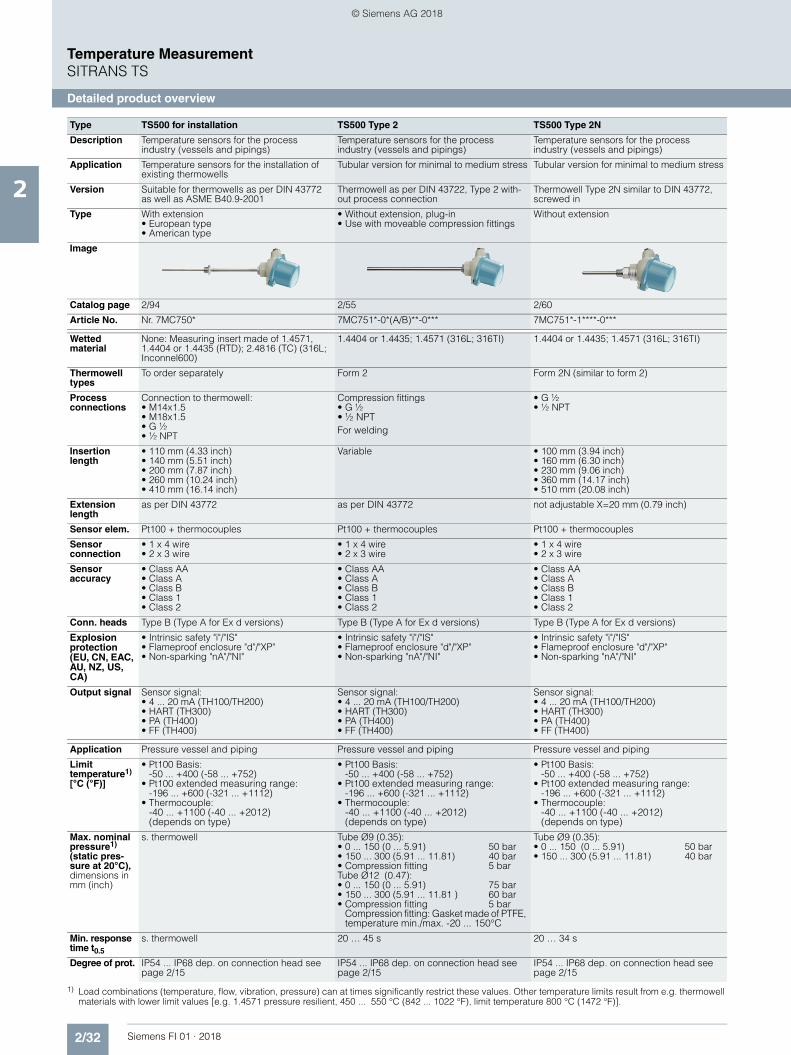
2/32 Siemens FI 01 · 2018
Temperature MeasurementSITRANS TS
Detailed product overview
2
1) Load combinations (temperature, flow, vibration, pressure) can at times significantly restrict these values. Other temperature limits result from e.g. thermowell materials with lower limit values [e.g. 1.4571 pressure resilient, 450 ... 550 °C (842 ... 1022 °F), limit temperature 800 °C (1472 °F)].
Type TS500 for installation TS500 Type 2 TS500 Type 2N
Description Temperature sensors for the process industry (vessels and pipings)
Temperature sensors for the process industry (vessels and pipings)
Temperature sensors for the process industry (vessels and pipings)
Application Temperature sensors for the installation of existing thermowells
Tubular version for minimal to medium stress Tubular version for minimal to medium stress
Version Suitable for thermowells as per DIN 43772 as well as ASME B40.9-2001
Thermowell as per DIN 43722, Type 2 with-out process connection
Thermowell Type 2N similar to DIN 43772, screwed in
Type With extension • European type • American type
• Without extension, plug-in• Use with moveable compression fittings
Without extension
Image
Catalog page 2/94 2/55 2/60
Article No. Nr. 7MC750* 7MC751*-0*(A/B)**-0*** 7MC751*-1****-0***
Wettedmaterial
None: Measuring insert made of 1.4571, 1.4404 or 1.4435 (RTD); 2.4816 (TC) (316L; Inconnel600)
1.4404 or 1.4435; 1.4571 (316L; 316TI) 1.4404 or 1.4435; 1.4571 (316L; 316TI)
Thermowell types
To order separately Form 2 Form 2N (similar to form 2)
Process connections
Connection to thermowell:• M14x1.5• M18x1.5• G ½• ½ NPT
Compression fittings • G ½ • ½ NPT For welding
• G ½ • ½ NPT
Insertion length
• 110 mm (4.33 inch) • 140 mm (5.51 inch) • 200 mm (7.87 inch)• 260 mm (10.24 inch)• 410 mm (16.14 inch)
Variable • 100 mm (3.94 inch)• 160 mm (6.30 inch)• 230 mm (9.06 inch)• 360 mm (14.17 inch)• 510 mm (20.08 inch)
Extension length
as per DIN 43772 as per DIN 43772 not adjustable X=20 mm (0.79 inch)
Sensor elem. Pt100 + thermocouples Pt100 + thermocouples Pt100 + thermocouples
Sensor connection
• 1 x 4 wire • 2 x 3 wire
• 1 x 4 wire • 2 x 3 wire
• 1 x 4 wire • 2 x 3 wire
Sensor accuracy
• Class AA• Class A• Class B• Class 1• Class 2
• Class AA• Class A• Class B• Class 1• Class 2
• Class AA• Class A• Class B• Class 1• Class 2
Conn. heads Type B (Type A for Ex d versions) Type B (Type A for Ex d versions) Type B (Type A for Ex d versions)
Explosion protection (EU, CN, EAC, AU, NZ, US, CA)
• Intrinsic safety "i"/"IS"• Flameproof enclosure "d"/"XP"• Non-sparking "nA"/"NI"
• Intrinsic safety "i"/"IS"• Flameproof enclosure "d"/"XP"• Non-sparking "nA"/"NI"
• Intrinsic safety "i"/"IS"• Flameproof enclosure "d"/"XP"• Non-sparking "nA"/"NI"
Output signal Sensor signal:• 4 ... 20 mA (TH100/TH200)• HART (TH300)• PA (TH400)• FF (TH400)
Sensor signal:• 4 ... 20 mA (TH100/TH200)• HART (TH300)• PA (TH400)• FF (TH400)
Sensor signal:• 4 ... 20 mA (TH100/TH200)• HART (TH300)• PA (TH400)• FF (TH400)
Application Pressure vessel and piping Pressure vessel and piping Pressure vessel and piping
Limit temperature1)
[°C (°F)]
• Pt100 Basis: -50 ... +400 (-58 ... +752)
• Pt100 extended measuring range:-196 ... +600 (-321 ... +1112)
• Thermocouple: -40 ... +1100 (-40 ... +2012) (depends on type)
• Pt100 Basis: -50 ... +400 (-58 ... +752)
• Pt100 extended measuring range:-196 ... +600 (-321 ... +1112)
• Thermocouple: -40 ... +1100 (-40 ... +2012) (depends on type)
• Pt100 Basis: -50 ... +400 (-58 ... +752)
• Pt100 extended measuring range:-196 ... +600 (-321 ... +1112)
• Thermocouple: -40 ... +1100 (-40 ... +2012) (depends on type)
Max. nominal pressure1)
(static pres-sure at 20°C),dimensions in mm (inch)
s. thermowell Tube Ø9 (0.35):• 0 ... 150 (0 ... 5.91) 50 bar• 150 ... 300 (5.91 ... 11.81) 40 bar• Compression fitting 5 barTube Ø12 (0.47):• 0 ... 150 (0 ... 5.91) 75 bar• 150 ... 300 (5.91 ... 11.81 ) 60 bar• Compression fitting 5 bar
Compression fitting: Gasket made of PTFE, temperature min./max. -20 ... 150°C
Tube Ø9 (0.35):• 0 ... 150 (0 ... 5.91) 50 bar• 150 ... 300 (5.91 ... 11.81) 40 bar
Min. response time t0.5
s. thermowell 20 … 45 s 20 … 34 s
Degree of prot. IP54 ... IP68 dep. on connection head see page 2/15
IP54 ... IP68 dep. on connection head see page 2/15
IP54 ... IP68 dep. on connection head see page 2/15
© Siemens AG 2018

2/33Siemens FI 01 · 2018
Temperature MeasurementSITRANS TS
Detailed product overview
2
1) Load combinations (temperature, flow, vibration, pressure) can at times significantly restrict these values. Other temperature limits result from e.g. thermowell materials with lower limit values [e.g. 1.4571 pressure resilient, 450 ... 550 °C (842 ... 1022 °F), limit temperature 800 °C (1472 °F)].
Type TS500 Type 2G TS500 Type 2F TS500 Type 3
Description Temperature sensors for the process industry (vessels and pipings)
Temperature sensors for the process industry (vessels and pipings)
Temperature sensors for the process industry (vessels and pipings)Quicker than form 2
Application Pipe version for minimal to medium stress Pipe version for minimal to medium stress Pipe version for minimal to medium stress
Version Thermowell as per DIN 43722, Type 2G, screwed in
Thermowell as per DIN 43722, Type 2F with flange
Thermowell as per DIN 43722, Type 3 with-out process connection, improved response time
Type With extension With extension • Without extension, plug-in• Use with moveable compression fittings
Image
Catalog page 2/65 2/70 2/75
Article No. 7MC751*-1*(A/B)**-1*** 7MC751*-2*(A/B)**-1*** 7MC751*-0*K**-0***
Wetted mater. 1.4404 or 1.4435; 1.4571 (316L; 316TI) 1.4404 or 1.4435; 1.4571 (316L; 316TI) 1.4404 or 1.4435; 1.4571 (316L; 316TI)
Therm. types Form 2G Form 2F Form 3
Process connections
Welded threads:• G 1• G ½• ½ NPT
Welded flange• DN 25, PN10 ... 40• 1RF150• 1.5RF150• 1.5RF300
Compression fittings• G ½ • ½ NPT For welding
Insertion length
• 160 mm (6.30 inch)• 250 mm (9.84 inch)• 400 mm (15.75 inch)
• 225 mm (8.86 inch)• 315 mm (12.40 inch)• 465 mm (18.31 inch)
• 225 mm (8.86 inch)• 315 mm (12.40 inch)• 465 mm (18.31 inch)
Extension length
As per DIN 43772 As per DIN 43772 As per DIN 43772
Sensor elements
Pt100 + thermocouples Pt100 + thermocouples Pt100 + thermocouples
Sensor connection
• 1 x 4 wire • 2 x 3 wire
• 1 x 4 wire • 2 x 3 wire
• 1 x 4 wire • 2 x 3 wire
Sensoraccuracy
• Class AA• Class A• Class B• Class 1• Class 2
• Class AA• Class A• Class B• Class 1• Class 2
• Class AA• Class A• Class B• Class 1• Class 2
Connection heads
Type B (Type A for Ex d versions) Type B (Type A for Ex d versions) Type B (Type A for Ex d versions)
Explosion protection (EU, CN, EAC, AU, NZ, US, CA)
• Intrinsic safety "i"/"IS"• Flameproof enclosure "d"/"XP"• Non-sparking "nA"/"NI"
• Intrinsic safety "i"/"IS"• Flameproof enclosure "d"/"XP"• Non-sparking "nA"/"NI"
• Intrinsic safety "i"/"IS"• Flameproof enclosure "d"/"XP"• Non-sparking "nA"/"NI"
Output signal Sensor signal:• 4 ... 20 mA (TH100/TH200)• HART (TH300)• PA (TH400)• FF (TH400)
Sensor signal:• 4 ... 20 mA (TH100/TH200)• HART (TH300)• PA (TH400)• FF (TH400)
Sensor signal:• 4 ... 20 mA (TH100/TH200)• HART (TH300)• PA (TH400)• FF (TH400)
Application Pressure vessel and piping Pressure vessel and piping Pressure vessel and piping
Limit temperat.1)
[°C (°F)]
• Pt100 Basis:-50 ... +400 (-58 ... +752 )
• Pt100 extended measuring range:-196 ... +600 (-321 ... +1112 )
• Thermocouple: -40 ... +1100 (-40 ... +2012) (depends on type)
• Pt100 Basis:-50 ... +400 (-58 ... +752 )
• Pt100 extended measuring range:-196 ... +600 (-321 ... +1112 )
• Thermocouple: -40 ... +1100 (-40 ... +2012) (depends on type)
• Pt100 Basis:-50 ... +400 (-58 ... +752 )
• Pt100 extended measuring range:-196 ... +600 (-321 ... +1112 )
• Thermocouple: -40 ... +1100 (-40 ... +2012) (depends on type)
Max. nominal pressure1)
(static pres-sure at 20°C),dimensions in mm (inch)
Tube Ø9 (0.35 ):• 0 ... 150 mm (0 ... 5.91 inch) 50 bar• 150 ... 300 (5.91 ... 11.81) 40 bar• Compression fitting 5 barTube Ø12 (0.47):• 0 ... 150 (0 ... 5.91) 75 bar• 150 ... 300 (5.91 ... 11.81) 60 bar
Tube Ø9 (0.35 ):• 0 ... 150 mm (0 ... 5.91 inch) 50 bar• 150 ... 300 (5.91 ... 11.81) 40 barTube Ø12 (0.47):• 0 ... 150 (0 ... 5.91) 75 bar• 150 ... 300 (5.91 ... 11.81) 60 barNote restriction imposed by PN of the flange
Tube Ø12 (0.47):• 0 ... 200 (0 ... 7.87) 75 bar• 200 ... 300 mm (7.87 ... 11.81) 60 bar• Compression fitting 5 bar
Compression fitting: Gasket made of PTFE, temperature min./max. -20 ... 150°C
Min. response time t0.5
20 … 34 s 20 … 34 s 7 … 15 s
Degr. of protec. IP54 ... IP68 dep. on connection head see page 2/15
IP54 ... IP68 dep. on connection head see page 2/15
IP54 ... IP68 dep. on connection head see page 2/15
© Siemens AG 2018
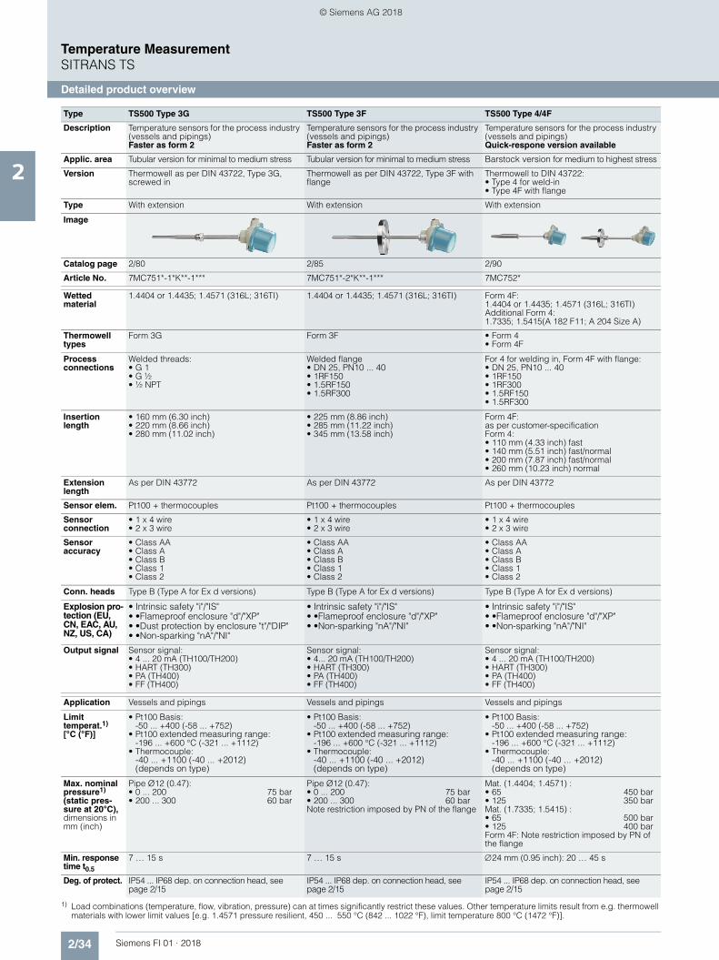
2/34 Siemens FI 01 · 2018
Temperature MeasurementSITRANS TS
Detailed product overview
2
1) Load combinations (temperature, flow, vibration, pressure) can at times significantly restrict these values. Other temperature limits result from e.g. thermowell materials with lower limit values [e.g. 1.4571 pressure resilient, 450 ... 550 °C (842 ... 1022 °F), limit temperature 800 °C (1472 °F)].
Type TS500 Type 3G TS500 Type 3F TS500 Type 4/4F
Description Temperature sensors for the process industry (vessels and pipings)Faster as form 2
Temperature sensors for the process industry (vessels and pipings)Faster as form 2
Temperature sensors for the process industry (vessels and pipings)Quick-respone version available
Applic. area Tubular version for minimal to medium stress Tubular version for minimal to medium stress Barstock version for medium to highest stress
Version Thermowell as per DIN 43722, Type 3G, screwed in
Thermowell as per DIN 43722, Type 3F with flange
Thermowell to DIN 43722:• Type 4 for weld-in• Type 4F with flange
Type With extension With extension With extension
Image
Catalog page 2/80 2/85 2/90
Article No. 7MC751*-1*K**-1*** 7MC751*-2*K**-1*** 7MC752*
Wetted material
1.4404 or 1.4435; 1.4571 (316L; 316TI) 1.4404 or 1.4435; 1.4571 (316L; 316TI) Form 4F:1.4404 or 1.4435; 1.4571 (316L; 316TI)Additional Form 4:1.7335; 1.5415(A 182 F11; A 204 Size A)
Thermowell types
Form 3G Form 3F • Form 4• Form 4F
Process connections
Welded threads:• G 1• G ½• ½ NPT
Welded flange • DN 25, PN10 ... 40• 1RF150• 1.5RF150• 1.5RF300
For 4 for welding in, Form 4F with flange:• DN 25, PN10 ... 40• 1RF150• 1RF300• 1.5RF150• 1.5RF300
Insertion length
• 160 mm (6.30 inch)• 220 mm (8.66 inch)• 280 mm (11.02 inch)
• 225 mm (8.86 inch)• 285 mm (11.22 inch)• 345 mm (13.58 inch)
Form 4F:as per customer-specificationForm 4:• 110 mm (4.33 inch) fast• 140 mm (5.51 inch) fast/normal• 200 mm (7.87 inch) fast/normal• 260 mm (10.23 inch) normal
Extension length
As per DIN 43772 As per DIN 43772 As per DIN 43772
Sensor elem. Pt100 + thermocouples Pt100 + thermocouples Pt100 + thermocouples
Sensor connection
• 1 x 4 wire • 2 x 3 wire
• 1 x 4 wire • 2 x 3 wire
• 1 x 4 wire • 2 x 3 wire
Sensor accuracy
• Class AA• Class A• Class B• Class 1• Class 2
• Class AA• Class A• Class B• Class 1• Class 2
• Class AA• Class A• Class B• Class 1• Class 2
Conn. heads Type B (Type A for Ex d versions) Type B (Type A for Ex d versions) Type B (Type A for Ex d versions)
Explosion pro-tection (EU, CN, EAC, AU, NZ, US, CA)
• Intrinsic safety "i"/"IS" • •Flameproof enclosure "d"/"XP"• •Dust protection by enclosure "t"/"DIP"• •Non-sparking "nA"/"NI"
• Intrinsic safety "i"/"IS"• •Flameproof enclosure "d"/"XP"• •Non-sparking "nA"/"NI"
• Intrinsic safety "i"/"IS"• •Flameproof enclosure "d"/"XP"• •Non-sparking "nA"/"NI"
Output signal Sensor signal:• 4 ... 20 mA (TH100/TH200)• HART (TH300)• PA (TH400)• FF (TH400)
Sensor signal:• 4... 20 mA (TH100/TH200)• HART (TH300)• PA (TH400)• FF (TH400)
Sensor signal:• 4 ... 20 mA (TH100/TH200)• HART (TH300)• PA (TH400)• FF (TH400)
Application Vessels and pipings Vessels and pipings Vessels and pipings
Limit temperat.1)
[°C (°F)]
• Pt100 Basis: -50 ... +400 (-58 ... +752)
• Pt100 extended measuring range: -196 ... +600 °C (-321 ... +1112)
• Thermocouple: -40 ... +1100 (-40 ... +2012) (depends on type)
• Pt100 Basis: -50 ... +400 (-58 ... +752)
• Pt100 extended measuring range:-196 ... +600 °C (-321 ... +1112)
• Thermocouple: -40 ... +1100 (-40 ... +2012) (depends on type)
• Pt100 Basis: -50 ... +400 (-58 ... +752)
• Pt100 extended measuring range: -196 ... +600 °C (-321 ... +1112)
• Thermocouple: -40 ... +1100 (-40 ... +2012) (depends on type)
Max. nominal pressure1)
(static pres-sure at 20°C),dimensions in mm (inch)
Pipe Ø12 (0.47):• 0 ... 200 75 bar• 200 ... 300 60 bar
Pipe Ø12 (0.47):• 0 ... 200 75 bar• 200 ... 300 60 barNote restriction imposed by PN of the flange
Mat. (1.4404; 1.4571) :• 65 450 bar• 125 350 barMat. (1.7335; 1.5415) :• 65 500 bar• 125 400 barForm 4F: Note restriction imposed by PN of the flange
Min. response time t0.5
7 … 15 s 7 … 15 s 24 mm (0.95 inch): 20 … 45 s
Deg. of protect. IP54 ... IP68 dep. on connection head, see page 2/15
IP54 ... IP68 dep. on connection head, see page 2/15
IP54 ... IP68 dep. on connection head, see page 2/15
© Siemens AG 2018

2/35Siemens FI 01 · 2018
Temperature MeasurementSITRANS TS
Detailed product overview
2
Type TS Thermowells 7MT14.. TS Thermowells 7MT2.. TS Thermowells 7MT3.. TS Thermowells 7MT4.. TS Thermowells 7MT5..
Description Thermometer thermowells for the process industry
Application Barstock version for medium to extreme stress
Version Thermowell according to DIN 43772
Thermowell according to ASME B40.9
Type With flange connection or for welding
For screwing in For welding With flange connection Van Stone version
Catalog page 2/104 2/107 2/107 2/108 2/108
Article No. 7MT14.. 7MT21.. (straight)7MT22.. (reduced)7MT23.. (tapered)
7MT31.. (straight)7MT32.. (reduced)7MT33.. (tapered)
7MT41.. (straight)7MT42.. (reduced)7MT43.. (tapered)
7MT51.. (straight)7MT52.. (reduced)7MT53.. (tapered)
Material, in contact with media
• 316Ti/1.4571• 316L/1.4404 • Hastelloy C276/2.4819• 1.5415 Heat-resistant• 1.7335 Heat-resistant• PTFE coating
(thermowell made of 316/TI/L)
• ECTFE (HALAR) thermowell made of 316/TI/L)
• Stellite coating (thermowell made of 316/TI/L)
• 316L/1.4404 • Carbon steel • 304L/1.4306• 321/1.4541
• 316L/1.4404 • Carbon steel • 304L/1.4306 • 321/1.4541
• 316L/1.4404 • Carbon steel • Hastelloy C276/2.4819• Hastelloy C22/2.4602 • 304L / 1.4306 • 321 / 1.4541 • Monel alloy 400/2.4360• Tantal (sleeve, ther-
mowell made of 316/TI/L)
• Duplex/1.4462 • Super Duplex • PTFE coating
(thermowell made of 316/TI/L)
• ECTFE (HALAR) (ther-mowell made of 316/TI/L)
• Stellite coating (thermowell made of 316/TI/L)
• 316L/1.4404 • Hastelloy C276/2.4819• Hastelloy C22/2.4602• 304L / 1.4306 • 321 / 1.4541 • Monel alloy 400/2.4360• Duplex/1.4462 • Superduplex• Tantalum coating on
316• PTFE coating
thermowell made of 316/TI/L)
• ECTFE (HALAR) thermowell made of 316/TI/L)
• Stellite coating thermowell made of 316/TI/L)
Thermowell forms
• Straight/tapered • straight• reduced (staggered)• tapered
Process con-nections
• Without (for direct weld-ing)
• Flange connection• EN 1092-1:
DN 40, 50/PN 10-16, 25-40
• ASME B16.5: 1,5" 2"/Class 150, 300, 600
• M20x1.5• M27x2.0• M33x2,0• 1/2-14 NPT• 3/4 NPT• 1 NPT• G1/2• G3/4• G1• R1/2• R3/4• R1
• 26.7 mm• 33.4 mm• 48.3 mm
• EN 1092-1: DN 25, 40, 50/PN 10-16, 25-40
• ASME B16.5: 1", 1,5, "2", 3", 4"/Class 150, 300, 600
• 33,4 mm/51 mm• 48,3 mm/73 mm• 60,3 mm/92 mm+ collar flangesASME B16.5: 1", 1,5" 2"/Class 150, 300, 600
Installation length
Standard lenght and free configuration
Extension length
Standard lenght and free configuration
Explosion protection
Not Ex-relevant, but offers zone separation when wall thickness of 1 mm for anti-corrosive materials, or otherwise 3 mm is observed. Not for coated versions.
Application Pipelines and containers
Limit temperatures
Material-dependent
Max. static pressure
Material-dependent
Min. response time
20 s... several minutes
Degree of protection
but offers zone separation when wall thickness of 1 mm for anti-corrosive materials, or otherwise 3 mm is observed
FI01_2018_en_kap02_SITRANS_TS_update_2017-11-28.fm Seite 35 Dienstag, 5. Juni 2018 8:10 08
© Siemens AG 2018

2/36 Siemens FI 01 · 2018
Temperature MeasurementSITRANS TS
Conversion assistance old appliance
2
OldL
eng
th
Mat
eria
l
Nu
mb
er o
f se
nso
rs +
Ex
Co
nn
ecti
on
hea
d
New
Mat
eria
l
PA w
eig
hts
PA c
har
acte
rist
ic
Th
erm
owel
l fo
rm
Len
gth
of
1st
dig
it
Len
gth
of
2nd
dig
it
- Ext
ensi
on
Co
nn
ecti
on
sid
e
Sen
sor
typ
e
Nu
mb
er o
f se
nso
rs
Ex
pro
tect
ion
7MC1006- 7 D 7 1 7 7MC751
1 - 1 C A 7 7 - 0 7 A 7
1 0 1
2 0 4
3 1 0
4 2 0
5 3 1
A 1 -Z E01
B 5 -Z E01
E 1 -Z E01
F 5 -Z E01
1 A
4 B
6 C
7 -
7MC1007- 7 D 7 1 7 7MC751
1 - 1 C A 7 7 - 1 7 C 7
5 0 4
6 1 2
7 2 2
A 1 -Z E01
B 5 -Z E01
E 1 -Z E01
F 5 -Z E01
1 A
4 B
6 C
7 -
7MC1008- 7 D 7 1 7 7MC751
1 - 1 E B 7 7 - 1 7 C 7 -Z E01
6 0 4
7 1 2
A 1
B 5
1 A
4 B
6 C
7 -
© Siemens AG 2018

2/37Siemens FI 01 · 2018
Temperature MeasurementSITRANS TS
Conversion assistance old appliance
2
7MC1010- 7 7 7 2 * 7MC752
7 - 0 N 7 7 0 - 7 7 C 7
1 A 0 1
2 A 0 9 N2D: X45 {Y45:209 mm}
3 A 0 9 N2D: X45 {Y45:179 mm}
4 B 0 1
5 B 0 9 N2D: X45 {Y45:179 mm}
6 D 0 1
7 D 0 9 N2D: X45 {Y45:179 mm}
8 E 0 9 N1D: X45 {Y45:119 mm}
G 3
F 1
A 1 -Z E01
B 5 -Z E01
E 1 -Z E01
F 5 -Z E01
1 A
4 B
6 C
7 -
7MC1017- 7 F 7 1 7 7MC751
1 - 2 A B 7 7 - 9 7 C 7 N2D: X45 {Y45:129 mm}
1 0 4
2 1 2
A 1 -Z E01
B 5 -Z E01
E 1 -Z E01
F 5 -Z E01
1 A
4 B
6 C
7 -
7MC1041- 7 F 7 0 7 7MC751
1 - 2 A K 7 7 - 1 7 C 7
1 1 1
2 1 4
3 1 7
A A 1 -Z E01
A B 5 -Z E01
E A 1 -Z E01
E B 5 -Z E01
1 A
4 B
6 C
7 -
OldL
eng
th
Mat
eria
l
Nu
mb
er o
f se
nso
rs +
Ex
Co
nn
ecti
on
hea
d
New
Mat
eria
l
PA w
eig
hts
PA c
har
acte
rist
ic
Th
erm
ow
ell f
orm
Len
gth
of
1st
dig
it
Len
gth
of
2nd
dig
it
- Ext
ensi
on
Co
nn
ecti
on
sid
e
Sen
sor
typ
e
Nu
mb
er o
f se
nso
rs
Ex
pro
tect
ion
© Siemens AG 2018

2/38 Siemens FI 01 · 2018
Temperature MeasurementSITRANS TS
Conversion assistance old appliance
2
OldL
eng
th
Nu
mb
er o
f se
nso
rs
Co
nn
ecti
on
hea
d
New
Dia
met
er
Mea
suri
ng
inse
rt t
ype
Sen
sor
Nu
mb
er o
f se
nso
rs
Len
gth
of
1st
dig
it
Len
gth
of
2nd
dig
it
Ex
pro
tect
ion
7MC1900- 7 E A 7MC701
8 - 1 C A 7 7 -Z E01
1 3 3
2 4 1
3 4 7 -Z Y44: B=1025 mm
4 4 7 -Z Y44: B=1425 mm
7MC1910- 7 J 7 7MC701
6 - 1 C 7 7 7
1 1 3
2 1 7
3 2 1
4 2 3
5 2 5
6 2 7
7 3 5
8 2 0
A A
B D
7MC1913- 7 A 7 7 2 7MC701
6 - 1 C 7 7 7 -Z E01
1 1 3
2 1 7
3 2 1
4 2 3
5 2 5
6 2 7
7 2 0
8 3 5
A 2 A
B 1 D
Old
Len
gth
Typ
e o
f ca
ble
Ext
ern
al d
iam
eter
of
shea
th New
Ext
ern
al d
iam
eter
of
shea
th
No
min
al le
ng
th
Sen
sor
Nu
mb
er o
f se
nso
rs
Co
nn
ecti
on
sid
e
Ex-
pro
tect
ion
7MC2027- 7 7 A 7 0 7MC711
1 - 7 7 K 1 1 - 0 A A 0 -Z E01
1 B
2 D -Z Y44: U=300 mm
3 D
A -Z J03
B -Z S03
C -Z L03
1 -
2 -
3 -
4 -
© Siemens AG 2018

2/39Siemens FI 01 · 2018
Temperature MeasurementSITRANS TS
Conversion assistance old appliance
2
OldE
xter
nal
dia
met
er o
f sh
eath
Mat
eria
l of
shea
th
Typ
e +
nu
mb
er o
f se
nso
r
Len
gth
New
Ext
ern
al d
iam
eter
of
shea
th
Len
gth
Sen
sor
typ
e
Nu
mb
er
Ex-
pro
tect
ion
7MC2021- 7 7 7 -Z 7MC721
2 - 7 7 7 7 5 - 0 A A 0 -Z E01
2 3
4 6
C
L
E J 1
F J 4
A - -
B - -
C K 1
D K 4
A01 C -Z Y44: U=250 mm
A02 F
A03 M
A04 T
Old
Len
gth
Nu
mb
er o
f se
nso
rs
Ext
ern
al d
iam
eter
of
shea
th
Mat
eria
l of
shea
th
New
Ext
ern
al d
iam
eter
of
shea
th
Len
gth
Sen
sor
typ
e
Nu
mb
er
Ex-
pro
tect
ion
7MC2028- 7 A 7 7 7 7MC721
2 - 7 7 K 7 4 - 0 A A 0 -Z E01
1 D -Z Y44: U=300 mm
2 D
C 1
D 4
1 -
2 -
3 3
4 6
1
2
© Siemens AG 2018

2/40 Siemens FI 01 · 2018
Temperature MeasurementSITRANS TS
Ordering examples
2
■ More information
Ordering examples for SITRANS TS100/200
Full article no.:
7MC7111-6CA11-Z A41+J10+Y15Y15: TTSA5458
Full article no.:
7MC7111-6CA11-Z A41+J10+Y15+Y44Y15: TTSA5458Y44: 211 mm
Ordering example for SITRANS TS500
Full article no.:
7MC7511-1EA12-9CA1-Z N2D+Y44+Y45 +Y33+Y33+Y33Y44: 220 mmY45: 200 mmY33: 0°CY33: 50°CY33: 150°C
Connection head, Form B Old New
• Made of cast light alloy, with 1 cable bushing and
- Screw cover 1 A
- Standard hinged cover 4 B
- Hinged cover high 6 C
• Made of stainless steel, with 1 cable bushing and screw cover 7 -
Measuring insert, single A 1
Measuring insert, single, explosion protection E 1 and additional E01
Measuring insert, double B 5
Measuring insert, double, explosion protection F 5 and additional E01
Desired features Article No.
SITRANS TS100 7MC7111
Sensor diameter 6
Standard length 200 mm (scope of sensor length 101 ... 250 mm)
C
Sensor A1
Flying leads 1
Enclosed compression fitting A41
Connection cable PVC, 10 m J10
TAG plate Y15: TTSA5458
Non-Ex requirements -Z E00
Desired features Article No.
SITRANS TS100 7MC7111
Sensor diameter 6
Standard length 200 mm (scope of sensor length 101 ... 250 mm)
C
Sensor A1
Flying leads 1
Enclosed compression fitting A41
Connection cable PVC, 10 m J10
TAG plate Y15: TTSA5458
Customer-specific length 211 mm Y44: 211 mm
Non-Ex requirements -Z E00
Desired features Article No.
SITRANS TS500 7MC751
Material 1
Process connection 1E
Thermowell form A
Insertion length U Standard 250 mm (insertion length customer-specific 220 mm)
12
Extension X customer-specific 9
Head C
Sensor A
Sensor number/Accuracy 1
Extension X customer-specific N2D
Insertion length U customer-specific Y44: 220 mm
Extension length X customer-specific Y45: 200 mm
Plant calibration per 3-point Y33: 0°CY33: 50°CY33: 150°C
Non-Ex requirements -Z E00
© Siemens AG 2018

2/41Siemens FI 01 · 2018
Temperature MeasurementSITRANS TS100
Cable, mineral-insulated
2
■ Dimensional drawings
SITRANS TS100, temperature sensors in cable version, universal use, mineral-insulated version, for unfavorable space conditions, IP54 at sen-sor/cable transition, dimensions in mm (inch)
Design of connection side
Flying leads, IP00, dimensions in mm (inch)
Coupling LEMO 1S, IP50, dimensions in mm (inch)
M12 device plug, IP54, dimensions in +mm (inch)
Thermocouple plug, IP20, dimensions in mm (inch)
B Measuring insert lengthØd Measuring insert outer diameter (6 (0.24))LC Cable lengthNBL Non-bending lengthTSL Temperature-sensitive lengthU Insertion length
10(0
.40)
U
B =
U +
10
(0.4
0)
TSL N
BL
90(3
.54)
LC90
(3.5
4)
Ød
40(1
.57)
Ø12(0.47)
60 (2
.36)
Ø19(0.75)
M12x1
25,4(1.0)
50(1
.97)
© Siemens AG 2018

2/42 Siemens FI 01 · 2018
Temperature MeasurementSITRANS TS100
Cable, mineral-insulated
2
1) Pt1000 versions are also available. To find these, please switch to Online Configuration in the PIA Life Cycle Portal: www.siemens.com/pia-portal
Additional configurations on page after next page!
You find ordering examples on page 2/40.
Selection and Ordering data Article No.
SITRANS TS100 7MC7111-Temperature sensors in cable version, uni-versal use, mineral-insulated version, for unfavorable space conditions
77777
Click on the Article No. for the online confi-guration in the PIA Life Cycle Portal.
Sensor diameter 6 mm (0.24 inch) 6
Length of sensor element B, effective length U = B-10; see dimensional drawings page 2/41
200 mm (7.87 inch) C 500 mm (19.68 inch) D 750 mm (29.53 inch) E
Customer-specific length of sensor ele-ment B, effective length U = B-10; see dimensional drawings page 2/41enter customer specific length with Y44, see Order codes below
70 ... 100 mm (2.76 ... 3.94 inch)Initial: 100 mm (3.94 inch)
B
101 ... 250 mm (3.98 ... 9.84 inch)Initial: 200 mm (7.87 inch)
C
251 ... 500 mm (9.88 ... 19.68 inch)Initial: 500 mm (19.68 inch)
D
501 ... 750 mm (19.72 ... 29.53 inch)Initial: 750 mm (29.53 inch)
E
751 ... 1 000 mm (19.72 ... 39.37 inch)Initial: 1 000 mm (39.37 inch)
F
1 001 ... 1500 mm (39.4 ... 59.00 inch)Initial: 1 500 mm (59.00 inch)
G
Special length: < 70 mm (2.76 inch) or > 1500 mm (59.00 inch)
X
Sensor1)
Please note: The accuracy class range can be lower than the measuring range. For more information, see page 2/17
Pt100, basis, -50 ... +400 °C (-58 ... +752 °F)
A
Pt100, vibration-resitant, -50 ... +400 °C (-58 ... +752 °F)
B
Pt100, expanded range, -196 ... +600 °C (-320.8 ... +1 112 °F)
C
Thermocouple Type K, -40 ... +1 000 °C (-40 .... +1 832 °F)
K
Thermocouple Type J, only class 2,-40 ... +750 °C (-40 ... +1 382 °F)
J
Sensor number/AccuracyCircuit Pt 100: 1 x 4-wire circuit or 2 x 3-wire circuit, see "Measuring technique:Connection types", page 2/19
Single, basic accuracy(Class 2/Class B)
1
Single, increased accuracy (Class 1/Class A)
2
Single, highest accuracy (Class AA)
3
Double, basic accuracy(Class 2/Class B)
4
Double, increased accuracy (Class 1/Class A)
5
Double, highest accuracy (Class AA)
6
Design of connection side
Flying leads 1 LEMO coupling 1S 2 M12 device plug, not for double Pt100 3 Thermocouple coupling, from TC-material (2xTC on request)
4
Selection and Ordering data Order code
Further designs
Add "-Z" to Article No. and specify Order code.
Customer-specific length of sensor element B, effective length U = B-10Select range, enter desired length in plain text (No entry = standard length)
Y44
Options
Add "-Z" to Article No., add options, separate extensions with "+".
Connection cable, type and lengthCable type = 1st letter, Length 1 ... 99 m (3.28 ... 324.80 ft) = 2nd + 3rd placee.g.: 34 m (111.55 ft) connection cable PVC(PVC code is J34)with X meters connection cable (JJ) PVC/PVC,Operating temperature (-10...+105°C) (14 ... 221 °F)
J01 ... J99
with X meters connection cable (SLFP) Silicone/Fluorpolymer, operating temperature -50 ... +180 °C (-58 ... +356 °F)
S01 ... S99
with X meters connection cable (TGLV) PTFE/glass fiber/reinforced with stainless steel), Operating tem-perature (-100...+205°C (148 ... 401°F))
L01 ... L99
© Siemens AG 2018
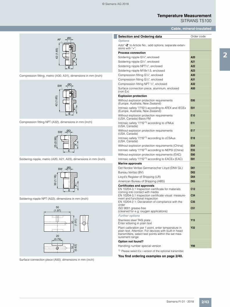
2/43Siemens FI 01 · 2018
Temperature MeasurementSITRANS TS100
Cable, mineral-insulated
2
Compression fitting, metric (A30, A31), dimensions in mm (inch)
Compression fitting NPT (A32), dimensions in mm (inch)
Soldering nipple, metric (A20, A21, A23), dimensions in mm (inch)
Soldering nipple NPT (A22), dimensions in mm (inch)
Surface connection piece (A50), dimensions in mm (inch)
1) Please select Ex i version of the optional transmitter.
You find ordering examples on page 2/40.
AF
42 (1
.65)
EE
ØD
K1
SW
42 (1
.65)
EE
ØD
K1
SW
25 (0
.98)
E
ØD
K1
SW
30 (1
.18)
E
ØD
K1
20(0.79)
50(1.97)
30(1
.81)
16(0
.63)
Selection and Ordering data Order code
Options
Add "-Z" to Article No., add options, separate exten-sions with "+".
Process connection
Soldering nipple G¼", enclosed A20
Soldering nipple G½", enclosed A21
Soldering nipple NPT½", enclosed A22
Soldering nipple M18x1.5, enclosed A23
Compression fitting G¼", enclosed A30
Compression fitting G½", enclosed A31
Compression fitting NPT ½", enclosed A32
Surface connection piece, aluminum, enclosed (non Ex)
A50
Explosion protection
Without explosion protection requirements(Europe, Australia, New Zealand)
E00
Intrinsic safety "i"/"IS1) according to ATEX and IECEx (Europe, Australia, New Zealand)
E01
Without explosion protection requirements (USA, Canada) Basis FM
E10
Intrinsic safety "i"/"IS"1) according to cFMus (USA, Canada)
E11
Without explosion protection requirements(USA, Canada)
E17
Intrinsic safety "i"/"IS"1) according to cCSAus(USA, Canada)
E18
Without explosion protection requirements (China) E54 Intrinsic safety "i"/"IS"1) according to NEPSI (China) E55 Without explosion protection requirements (EAC) E80 Intrinsic safety "i"/"IS"1) according to EACEx (EAC) E81 Marine approvals
Det Norske Veritas Germanischer Lloyd (DNV GL) D01 Bureau Veritas (BV) D02 Lloyd’s Register of Shipping (LR) D04 American Bureau of Shipping (ABS) D05 Certificates and approvals
EN 10204-3.1 Inspection certificate for materials coming into contact with media
C12
EN 10204-3.1 Inspection certificate visual: measure-ment and functional inspection
C34
EN 10204-2.1: Declaration of compliance with the order
C35
ISO 9001 grease-free (cleaned for e.g. oxygen applications)
C51
Further options
Stainless steel TAG plate , Enter lettering in plain text
Y15
Plant calibration per 1 point, enter temperature in plain text, Attention: For devices with built-in head transmitters, select test points within the set mea-surement range
Y33
Option not found?
Handling number special version Y99
© Siemens AG 2018

2/44 Siemens FI 01 · 2018
Temperature MeasurementSITRANS TS200
Compact, mineral-insulated
2
■ Dimensional drawings
SITRANS TS200, temperature sensors in cable version, universal use, mineral-insulated version, for unfavorable space conditions, dimensions in mm (inch)
Basic sensorFlying leads
Thermocouple coupling
LEMO coupling 1S
M12 device plugs
Mini connection head
Head heightMeasuring insert length
Insertion length
IP levelsensor
IP levelterminals
0
1
2
3
4
5
0
5432
11
2345
U = BU = B + 10 (0.39)U = B - 10 (0.39)
U = B - 10 (0.39) IP65U = B - 5 (0.20)U = B - 20 (0.79)
0
HB
U
U = B IP65U = B + 10 (0.39) IP65U = B - 10 (0.39) IP65
U = B - 5 (0.20) IP65IP65
IP54
IP00IP00IP50
IP65IP65
HB
U
U
B
15(1.59)
B
U150
(5.91)10
(0.39)
B
U50
(1.97)5
(0.20)
B
U40
(1.57)
U36
(1.41)
U 65 (2.56)
B
10(0.39)
10(0.39)
B
20(0.79)
© Siemens AG 2018

2/45Siemens FI 01 · 2018
Temperature MeasurementSITRANS TS200
Compact, mineral-insulated
21) Pt1000 versions are also available. To find these, please switch to Online
Configuration in the PIA Life Cycle Portal: www.siemens.com/pia-portal
Additional configurations on page after next page!
You find ordering examples on page 2/40.
Selection and Ordering data Article No.
SITRANS TS200 7MC7212-Temperature sensors in compact version, universal use, mineral-insulated version, for unfavorable space conditions
77777
Click on the Article No. for the online confi-guration in the PIA Life Cycle Portal.
Sensor diameter 6 mm (0.24 inch) 6
Length of sensor element B, effective length U see dimensional drawing on page 2/44
200 mm (7.87 inch) C 500 mm (19.68 inch) D 750 mm (29.53 inch) E
Customer-specific length of sensor ele-ment B, effective length U see dimensional drawing on page 2/44enter customer specific length with Y44, see Order codes below
70 ...100 mm (2.76 ... 3.94 inch)Initial: 100 mm (3.94 inch)
B
101 ... 250 mm (3.98 ... 9.84 inch)Initial: 200 mm (7.87 inch)
C
251 ... 500 mm (9.88 ... 19.68 inch)Initial: 500 mm (19.68 inch)
D
501 ... 750 mm (19.72 ... 29.53 inch)Initial: 750 mm (29.53 inch)
E
751 ... 1 000 mm (29.57 ... 39.37 inch)Initial: 1 000 mm (39.37 inch)
F
1 001 ... 1 500 mm (39.4 ... 59.00 inch)Initial: 1 500 mm (59.00 inch)
G
Special length: < 70 mm (2.76 inch) or > 1500 mm (59.00 inch)
X
Sensor1)
Please note: The accuracy class range can be lower than the measuring range. For more information, see page 2/17
Pt100, basis, -50 ... +400 °C (-58 ... +752 °F)
A
Pt100, vibration-resistant, -50 ... +400 °C (-58 ... +752 °F)
B
Pt100, expanded range, -196 ... +600 °C (-320.8 ... +1 112 °F)
C
Thermocouple Type K, -40 ... +1 000 °C(-40 ... +1 832 °F)
K
Thermocouple Type J, only class 2, -40 ... +750 °C (-40 ... +1 382 °F)
J
Number/AccuracyCircuit Pt 100: 1 x 4-wire circuit or2 x 3-wire circuit, see "Measuring technique:Connection types", page 2/19
Single, basic accuracy(Class 2/Class B)
1
Single, increased accuracy (Class 1/Class A)
2
Single, highest accuracy (Class AA)
3
Double, basic accuracy(Class 2/Class B)
4
Double, increased accuracy (Class 1/Class A)
5
Double, highest accuracy (Class AA)
6
Design of connection side
Solid wire ends (sensor element) 0 Flying leads 1 LEMO coupling 1S 2 M12 device plug, not for double Pt100 3 Thermocouple coupling, from TC-material (2xTC on request)
4
Mini connection head, aluminum, not for dou-ble Pt100
5
Selection and Ordering data Order code
Further designs
Add "-Z" to Article No. and specify Order code.
Customer-specific length of sensor element B, effective length, U see dimensional drawing on page 2/44Select range, enter desired length in plain text (No entry = standard length)
Y44
© Siemens AG 2018

2/46 Siemens FI 01 · 2018
Temperature MeasurementSITRANS TS200
Compact, mineral-insulated
2
Compression fitting, metric (A30, A31), dimensions in mm (inch)
Compression fitting NPT (A32), dimensions in mm (inch)
Soldering nipple, metric (A20, A21, A23), dimensions in mm (inch)
Soldering nipple NPT (A22), dimensions in mm (inch)
Surface connection piece (A50), dimensions in mm (inch)
1) Please select Ex i version of the optional transmitter.
You find ordering examples on page 2/40.Accessories, see page 2/237.
AF
42 (1
.65)
EE
ØD
K1
SW
42 (1
.65)
EE
ØD
K1
SW
25 (0
.98)
E
ØD
K1
SW
30 (1
.18)
E
ØD
K1
20(0.79)
50(1.97)
30(1
.81)
16(0
.63)
Selection and Ordering data Order code
Options
Add "-Z" to Article No., add options, separate exten-sions with "+".
Process connection
Soldering nipple G¼", enclosed A20
Soldering nipple G½", enclosed A21
Soldering nipple NPT½", enclosed A22
Soldering nipple M18x1.5, enclosed A23
Compression fitting G¼", enclosed A30
Compression fitting G½", enclosed A31
Compression fitting NPT½", enclosed A32
Surface connection piece, aluminum, enclosed (non Ex)
A50
Explosion protection
Without explosion protection requirements(Europe, Australia, New Zealand)
E00
Intrinsic safety "i"/"IS1) according to ATEX and IECEx (Europe, Australia, New Zealand)
E01
Without explosion protection requirements (USA, Canada) Basis FM
E10
Intrinsic safety "i"/"IS"1) according to cFMus (USA, Canada)
E11
Without explosion protection requirements(USA, Canada)
E17
Intrinsic safety "i"/"IS"1) according to cCSAus(USA, Canada)
E18
Without explosion protection requirements (China) E54 Intrinsic safety "i"/"IS"1) according to NEPSI (China) E55 Without explosion protection requirements (EAC) E80 Intrinsic safety "i"/"IS"1) according to EACEx (EAC) E81 Marine approvals
Det Norske Veritas Germanischer Lloyd (DNV GL) D01 Bureau Veritas (BV) D02 Lloyd’s Register of Shipping (LR) D04 American Bureau of Shipping (ABS) D05 Certificates and approvals
EN 10204-3.1 Inspection certificate for materials coming into contact with media
C12
EN 10204-3.1 Inspection certificate visual, measure-ment and functional inspection
C34
EN 10204-2.1: Declaration of compliance with the order
C35
ISO 9001 grease-free (cleaned for e.g. oxygen appli-cations)
C51
Setting, designation, calibration
Stainless steel TAG plate , Enter lettering in plain text
Y15
Plant calibration per 1 point, enter temperature in plain text. Attention: For devices with built-in head transmitters, select test points within the set measure-ment range
Y33
Option not found?
Handling number special version Y99
© Siemens AG 2018

2/47Siemens FI 01 · 2018
Temperature MeasurementSITRANS TS300
For food, pharmaceuticals and biotechnology modular design
2
■ Dimensional drawings
SITRANS TS300 modular design, dimensions in mm (inch)
Cable glandM12x1.5 for cable Ø 3 ... 6.5 (0.12 ... 0.26)
Ød Measuring insert outer diameter (6 (0.24))ØD Process connection outer diameterØD3 Protective pipe inner diameterH Head height
B Measuring insert length
N Nominal lengthU Insertion lengthX Extension length
Ø 50.5(1.99)
H1 Type Axx = 41 (1.61)Type Bxx = 26 (1.02)
U
N
X
Ø d
B =
N +
H1
Ø 60 (2.36)
Ø D3
Ø D
H
H1
© Siemens AG 2018

2/48 Siemens FI 01 · 2018
Temperature MeasurementSITRANS TS300
For food, pharmaceuticals and biotechnology modular design
2
Selection and Ordering data Article No. Order code
SITRANS TS300for food, pharmaceuticals and biotechnol-ogy, modular design for installation in pipelines and vessels
7MC8005-
7777 0 - 777 0 777
Click on the Article No. for the online con-figuration in the PIA Life Cycle Portal.
HeadStainless steel head, BS0, screw cover (Standard version)
5
Aluminum head, BA0, flange cover standard 1Plastic cover, BM0, srew cover 2Aluminum head, BB0, hinged cover low 3Aluminum head, BC0, hinged cover high 4Special version:(add Order code and plain text)
9 H 1 Y
Process connection, material 1.4404 or 1.4435/316LMilk pipe union to DIN 11851 with slotted union nut and nominal diameter/pressureDN 25/PN 40 A ADN 32/PN 40 A BDN 40/PN 40 A CDN 50/PN 25 A DClamp connection:
ISO 2852 DIN 32676
Tri-Clamp Outer diameter D
– – ½"/ ¾" 25.0 mm C ADN 25/ 33.7/38
DN 25/32/40
1", 1½" 50.5 mm C B
DN 40/51 DN 50 2" 64.0 mm C CDN 63.5 – 2½" 77.5 mm C DDN 88.9 DN 80 – 106.0 mm C E
Varivent connection (Tuchenhagen)D6 = 50 mm (1.97 inch),for Varivent housing DN 25 and DN 1"
K U
D6 = 68 mm (2.68 inch),for Varivent housing DN 40 ... 125 and 1½" ... 6"
K V
NEUMO/BioControlSize 25 B ASize 50 B BSize 65 B C
Ingold flangeDN 25 with hexagon union nut G 1¼", mounting length 40 mm (1.57"), diameter 24.8 mm (0.98") incl. O-ring
J A
Welding piece(sphere diameter 30 x 40 mm (1.2 x 1.6 inch) long)
L A
Special version:Type of screwed gland and nominal diame-ter (add Order code and plain text)
Z A J 1 Y
Protective tube Measuring insertØ D = 6 mm(0.24 inch)
Ø 3/3.2 mm, (0.12/0.13 inch)miner. insul.
1
Ø D =9 mm(0.35 inch)
Ø 6 mm (0.24 inch) 2
Ø D =9 mm(0.35 inch)
Ø 6 mm (0.24 inch)miner. insul.
3
Ø D =9 mm(0.35 inch)tapered tipD2 =5 Ø x 20 mm(0.2 x 0.79 inch)
Ø 3/3.2 mm, (0.12/0.12 inch)miner. insul.
4
Special version:(add Order code and plain text)
9 L 1 Y
Neck tube length X65 mm (2.56 inch) [M = 80 mm (3.15 inch)] 1130 mm (5.12 inch) [M = 145 mm (5.71 inch)] 2Special version:(add Order code and plain text)
9 N 1 Y
Insertion lengthEnter customer specific length with Y44, see Order codes below15 mm (0.59 inch) B16 ... 35 mm (0.63 ...1.38 inch)Initial: 35 mm (1.38 inch)
C
36 ... 50 mm (1.42 ... 1.97 inch)Initial: 50 mm (1.97 inch)
D
51 ... 100 mm (2.01 ... 3.94 inch)Initial: 100 mm (3.94 inch)
E
101 ... 160 mm (3.98 ... 6.30 inch)Initial: 160 mm (6.30 inch)
F
161 ... 250 mm (6.34 ... 9.84 inch)Initial: 250 mm (9.84 inch)
G
251 ... 400 mm (9.88 ... 15.75 inch)Initial: 400 mm (15.75 inch)
H
1 ... 4 inch, Initial: 4 inch J4 ... 6 inch, Initial: 6 inch K6 ... 9 inch, Initial: 9 inch LSpecial version:(add Order code and plain text)
Z P 1 Y
SensorThin-film technology:measuring range -50 ... +400 °C(-58 ... +752 °F)2 x Pt100, class A, three-wire G1 x Pt100, class A, four-wire HSpecial version:(add Order code and plain text)
Z Q 1 Y
Further designs Order codeAdd "-Z" to Article No. and add Order code
Process connection completely electropol-ished
P01
Hygiene version(Ra < 0.8 m (3.1 x 10⁻⁵ inch))
H01
Certificates• Roughness depth measurement Ra
certified by factory certificate to EN 10204-3.1
C18
• Material certificate to EN 10204-3.1 C12TAG plate made of stainless steelspecify TAG No. in plain text
Y15
Test report (at 0, 50 and 100%)specify measuring range in plain textIf optional head transmitters are integrated, please note that all calibration points are located in the set measuring range. If the points are located outside the standard measuring range, a Y01 addition is always required.
Y33
Insertion length customer-specificSelect range, enter desired length in plain text (No entry = standard length)
Y44
Selection and Ordering data Article No. Order code
SITRANS TS300for food, pharmaceuticals and biotechnol-ogy, modular design for installation in pipelines and vessels
7MC8005-
7777 0 - 777 0 777
© Siemens AG 2018
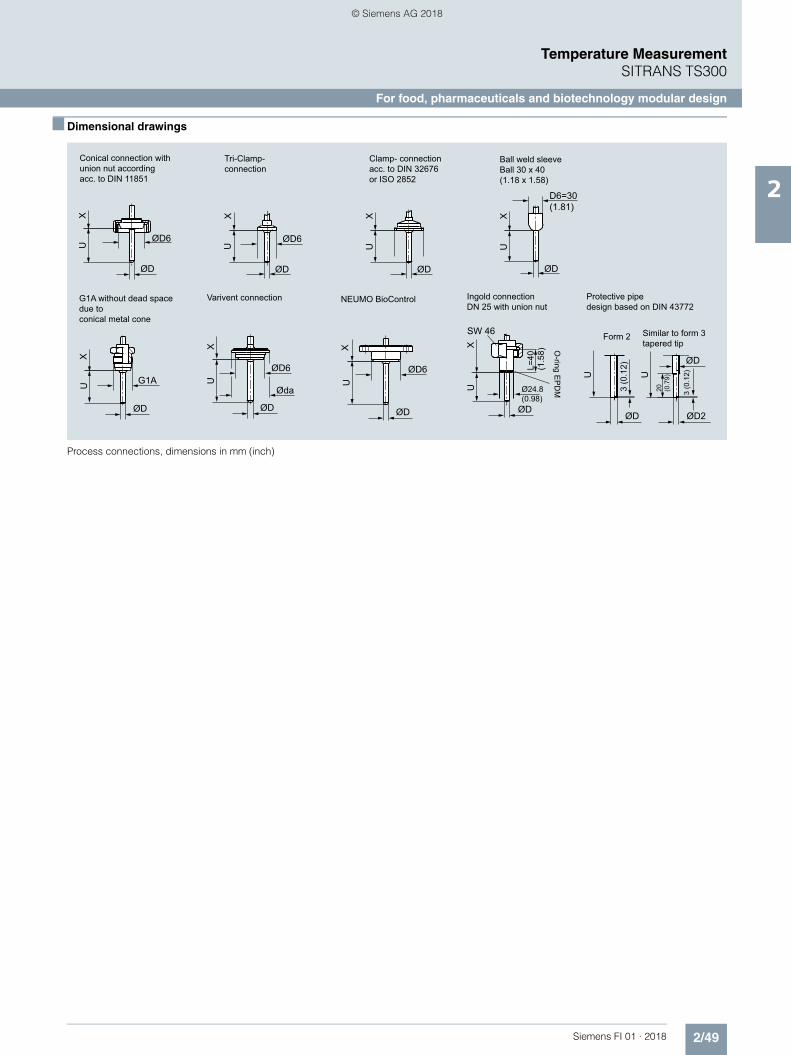
2/49Siemens FI 01 · 2018
Temperature MeasurementSITRANS TS300
For food, pharmaceuticals and biotechnology modular design
2
■ Dimensional drawings
Process connections, dimensions in mm (inch)
Clamp- connection acc. to DIN 32676 or ISO 2852
Ball weld sleeveBall 30 x 40 (1.18 x 1.58)
Conical connection with union nut according acc. to DIN 11851
Tri-Clamp- connection
G1A without dead spacedue to conical metal cone
NEUMO BioControl Ingold connection DN 25 with union nut
Varivent connection Protective pipe design based on DIN 43772
Ø24.8(0.98)
O-ring E
PD
M
SW 46 Form 2 Similar to form 3tapered tip
UX
ØD
UX
ØD
D6=30(1.81)
UX
ØD
ØD6U
X
ØD
ØD6
UX
ØD
G1A UX
ØD
UX
ØD
L=40
(1.5
8)
UX
ØD6 ØD6
ØD
Øda
U U
ØD
ØD
ØD2
3 (0
.12)
3 (0
.12)
20 (0.7
9)
© Siemens AG 2018

2/50 Siemens FI 01 · 2018
Temperature MeasurementSITRANS TS300
For food, pharmaceuticals and biotechnology modular design
2
Accessories, see page 2/237.
Selection and Ordering data Order code
Further designs
Add "-Z" to Article No. and specify Order code. Built-in head transmitterMeasuring range to be set must be specified with plain text data "Y11".
SITRANS TH100, 4 ... 20 mA, Pt100 T10
SITRANS TH100 Ex i (ATEX), 4 ... 20 mA, Pt100 T11
SITRANS TH200, 4 ... 20 mA, universal T20
SITRANS TH200 Ex i(ATEX), 4 ... 20 mA, universal T21
SITRANS TH300, HART, universal T30
SITRANS TH300 Ex i (ATEX), HART, universal T31
SITRANS TH400 PA, universal T40
SITRANS TH400 PA Ex i, universal T41
SITRANS TH400 FF, universal T45
SITRANS TH400 FF Ex i, universal T46 Transmitter options Transmitter, enter complete setting in plain text
(Y11:+/-NNNN ... +/-NNNN C,F)Y11
Enter measuring point (max. 8 characters) in plain text
Y17
Transmitter, enter measuring point description (max. 16 characters) in plain text
Y23
Transmitter, enter measuring point text (max. 32 characters) in plain text
Y24
Transmitter, enter bus address in plain text Y25 Transmitter, fail-safe value 3.6 mA
(instead of 22.8 mA)U36
Transmitter with a SIL 2 conformity C20
Transmitter with a SIL 2/3 conformity C23
Transmitter test protocol (5 points) C11 Further options
Connection form, flying leads (for the direct transmit-ter assembly, delivery without screws and springs)
G01
M12 device plug (in combination with 1x Pt100 and/or transmitter, Non-Ex)
G12
Option not found? Specify special version in plain text Y98 Process number for the special version Y99
© Siemens AG 2018

2/51Siemens FI 01 · 2018
Temperature MeasurementSITRANS TS300
For food, pharmaceuticals and biotechnology clamp-on design
2
■ Dimensional drawings
Resitance thermometer with protection pipe in Clamp-on design
12
3
45
6
7
8
9
1 Vibration-locking-screw2 Mounting screws3 Process pipeline4 Temperature sensor5 Thermal decoupling6 Spring load7 Electrical connection
M128 Replaceable measuring
insert9 Heat insulated pipe collar
© Siemens AG 2018

2/52 Siemens FI 01 · 2018
Temperature MeasurementSITRANS TS300
For food, pharmaceuticals and biotechnology clamp-on design
2
1) Special sizes for pipe outer diameters: In order to process "Z0" special sizes, the following two additional items of information are essential:- the required diameter specified in plain text under "K1Y"- Selection of the corresponding pipe collar, clamping band or clamping bracket size (Order codes "S11" to "S35")
Recommended for all versions: Heat-conductive-compound, silicone-free, syringe 3 g, Order code: L15 (see page 2/54)
Selection and Ordering data Article No. Ord. code
SITRANS TS300for food, pharmaceuticals and biotech-nologyClamp-on design for the measuring of the pipe surface temperature
7MC8016- 7777 0 777
Click on the Article No. for the online con-figuration in the PIA Life Cycle Portal.
Design Acc. to IEC 60751, class A [-40 ... +150 °C (-40 ... +302 °F)]
1
Type of connectionDevice plug M12 x 1 Aconnection head form B, stainless steel B4 ... 20 mA compact transmitter SITRANS TH100slim (standard measuring range 0 ... 100 °C (32 ... 212 °F))
C
Mounting with pipe collar
Pipe outer-Ø mm (inch)
Collar sizemm (inch)
4 (0.16)
50 x 35 x 20 (1.97 x 1.38 x 0.79)
A16 (0.24) B1
6.35 (0.25) C18 (0.31) D1
9.35 (0.37) E110 (0.39) F 1
10.2 (0.40) G110.3 (0.41) H1
12 (0.47) J 112.7 (0.50) K1
13 (0.51) L 113.5 (0.53) M1
13.7 (0.54) N114 (0.55) P1
15.88 (0.62) Q116 (0.63) R1
17.2 (0.68) S1
18.0 (0.71)
70 x 70 x 20 (2.76 x 2.76 x 0.79)
A219.0 (0.74) B2
19.05 (0.75) C220.0 (0.79) D2
21.3 (0.84) E222.0 (0.87) F 2
23.0 (0.90) G224.0 (0.94) H2
25.0 (0.98) J 225.4 (1.00) K2
26.7 (1.05) L 226.9 (1.06) M2
28.0 (1.10) N229.0 (1.14) P2
30.0 (1.18) Q231.8 (1.25) R2
32.0 (1.26) S233.4 (1.31) T 2
33.7 (1.33) U234.0 (1.34) V2
35.0 (1.38) W236.0 (1.42) X2
38.0 (1.49) Y2
38.1 (1.50) A341.0 (1.61) B3
42.4 (1.67) C344.5 (1.75) D3
48.3 (1.90) 90 x 85 x 20 (3.54 x 3.35 x 0.79)
E350.8 (2.00) F 3
53.0 (2.09) G354.0 (2.13) H3
57.0 (2.24) J 3
Always indicate external tube diameter for1):• Installation with tube collar and deviating
external tube diameter (S11-S19)• Securing with clamps (S21-S23)• Clamping band installation (S31-S35)
Z 0 K1 Y
Selection and Ordering data Article No. Ord. code
SITRANS TS300for food, pharmaceuticals and biotech-nologyClamp-on design for the measuring of the pipe surface temperature
7MC8016- 7777 0 777
© Siemens AG 2018

2/53Siemens FI 01 · 2018
Temperature MeasurementSITRANS TS300
For food, pharmaceuticals and biotechnology clamp-on design
2
■ Dimensional drawings
SITRANS TS300 Clamp-on design, device plug, field housing, cable gland, variants, dimensions in mm (inch)
Measuring transducer with device plug M12x1
Cable glandM16x1.5 for cable Ø4.5 ... 10 (0.18 ... 0.39)
Clamp-on, clamping band installationwith hose clampsfor pipelines ≥ Ø10 ... ca. 300 (0.39 ... ca.11.81)
Clamp-on,clamping block installationfor pipelines Ø4 ... 57 (0.16 ... 2.24)
Clamp-on,latch fastener installation for pipelinesØ4 ... 17.2 (0.16 ... 0.68)
Example Ø21 (4.76)
Pip
e ra
dius
Cable glandM12x1.5 for cable Ø3 ... 6.5 (0.12 ... 0.26)
Electrical connectioncan be rotated by ± 170 ˚
Device plugM12x1
Device plugM12x1
Field housing, screw cap Material stainless steel IP 67
~ 83
.5 (3
.70)
max
. 29
(1.4
1)
11.5(0.45)
Latch fastener version
Standard version
Pipe diameter B C 6 ... 17.2 30 35 (0.24 ... 0.68) (1.18) (1.38) 18 ... 35 40 60 (0.71 ... 1.38) (1.57) (2.36) 38 ... 50.8 50 80 (1.50 ... 2.00) (1.97) (3.15)
Pipe diameter A B C H 4 ... 17.2 20 30 35 79 (0.16 ... 0.68) (0.79) (1.18) (1.38) (3.11) 18 ... 38 30 40 70 99 (0.71 ... 1.49) (1.18) (1.57) (2.76) (3.90) 38.1 ... 57 40 50 85 119 (1.50 ... 2.24) (1.57) (1.97) (3.35) (4.68)
94 (3
.70)
36 (1.42)
19(0.75)
37(1.46)
19(0.75)
23(0
.91)
20(0.79)
20(0.79)
3 (0
.12) 6 (0.24)
51 (2
.01)
C
C
A
A
B
B
B
B
Ø60 (2.36)
© Siemens AG 2018

2/54 Siemens FI 01 · 2018
Temperature MeasurementSITRANS TS300
For food, pharmaceuticals and biotechnology clamp-on design
2
Accessories, see page 2/237.
Ordering examples:
Deviating tube diameter 28.5 mm:7MC8016-1AZ00-Z K1Y+S12 {K1Y: 28.5 mm}
Space-saving mounting, tube diameter 38 mm:7MC8016-1AZ00-Z K1Y + S23 {K1Y: 38 mm};as of diameter 18 mm, we recommend using the clamping band installation.
Clamping band installation, tube diameter 111 mm:7MC8016-1AZ00-Z K1Y+S32 {K1Y: 111 mm}
Selection and Ordering data Order code
Further designsAdd "-Z" to Article No. and specify Order code.
Built in head transmitterMeasuring range to be set must be specified with plain text data "Y11".
SITRANS TH100, 4 ... 20 mA, Pt100 T10 SITRANS TH100 Ex i (ATEX), 4 ... 20 mA, Pt100 T11 SITRANS TH200, 4 ... 20 mA, universal T20 SITRANS TH200 Ex i (ATEX), 4 ... 20 mA, universal T21 SITRANS TH300, HART, universal T30 SITRANS TH300 Ex i (ATEX), HART, universal T31 SITRANS TH400 PA, universal T40 SITRANS TH400 PA Ex i, universal T41 SITRANS TH400 FF, universal T45 SITRANS TH400 FF Ex i, universal T46 Transmitter options Transmitter, enter complete setting in plain text
(Y11:+/-NNNN ... +/-NNNN C,F)Y11
Enter measuring point (max. 8 characters) in plain text Y17 Transmitter, enter measuring point description
(max. 16 characters) in plain textY23
Transmitter, enter measuring point text (max. 32 characters) in plain text
Y24
Transmitter, enter bus address in plain text Y25 Transmitter, fail-safe value 3.6 mA
(instead of 22.8 mA)U36
Transmitter with a SIL 2 conformity C20
Transmitter with a SIL 2/3 conformity C23
Transmitter test protocol (5 points) C11
Other cable gland (only for connection head)Polyamide for cable diameter 4.5 … 10 mm (0.18 … 0.39 inch)
K02
Stainless steel for cable diameter 3 … 6,5 mm (0.12 … 0.25 inch)
K03
Device plug M12 x 1 K11
Deviating pipe; mm (inch)
Collar size; mm (inch)
4 … 17.2 (0.16 … 0.68) 50 x 35 (1.97 x 1.38) S1118 … 38 (0.71 … 1.49) 70 x 70 (2.76 x 2.76) S1238.1 … 57 (1.5 … 2.24) 90 x 85 (3.54 x 3.35) S13Larger nominal diameters on request S19
Space-saving mounting (latch fastening)Outer pipe; mm (inch):4 … 17.2 (0.16 … 0.68) S2118 … 35 (0.71 … 1.38)(Clamping band version recommended, see below)
S22
38 … 50.8 (1.45 … 2.00)(Clamping band version recommended, see below)
S23
Clamping band installation
Outer pipe; mm (inch):
10 ... 57 (0.39 ... 2.24) S31
58 ... 220 (2.28 ... 8.66) S32
Without clamping band S35
Further OptionsAssignment marking, engraving instead of adhesive label(Serial number and pipe diameter on plug and plastic block)
L11
2 mm drain hole L12Sensor 4-wire connection L14Heat-conductive-compound, silicone-free, syringe 3 g L15
Suffixes
Add "-Z" to Article No. and specify Order code and plain text.
TAG plate made of stainless steel (specify TAG No. in plain text)
Y15
Test report at 0 %, 50 % and 100 % (specify the measuring range in plain text)If optional head transmitters are integrated, please note that all calibration points are located in the set measuring range. If the points are located outside the standard mea-suring range, a Y01 addition is always required.
Y33
Special version, specify in plain text Y98Process number for special version Y99
Selection and Ordering data Order code
© Siemens AG 2018

2/55Siemens FI 01 · 2018
Temperature MeasurementSITRANS TS500
Type 2, tubular version without process connection
2
■ Dimensional drawings
SITRANS TS500, temperature sensors for vessels and pipings, tubular version for minimal to medium stress, without process connection, with-out extension, plug-in or use with moveable compression fittings, dimen-sions in mm (inch)
Ød Measuring insert outer diameter (6 (0.24))ØD Process connection outer diameterØD3 Thermowell internal diameterH Head height
B Measuring insert length
N Nominal lengthP Space for process connection P ~ N - 9 (0.35)
Cable entry
H1 Type Axx = 41 (1.61)Type Bxx = 26 (1.02)
Ød
ØD3
HN
B =
N +
H1
ØD
P 1
© Siemens AG 2018

2/56 Siemens FI 01 · 2018
Temperature MeasurementSITRANS TS500
Type 2, tubular version without process connection
2
Additional configurations on page after next page!
You find ordering examples on page 2/40!
Selection and Ordering data Article No.
SITRANS TS500 7MC751-Pipe version for minimal to medium stress, as per thermowell DIN 43722, Type 2, without process connection, without extension, plug-in or use with moveable compression fittings
7 - 77777 - 7777
Click on the Article No. for the online configuration in the PIA Life Cycle Por-tal.
Material, in contact with media
316Ti (1.4571) 1 316L (1.4404 or 1.4435) 2 Process connection
Without process connection (for compres-sion fitting) N=U
0 N
Thermowell form
2; 9 mm (0.35 inch) A 2; 12 mm (0.47 inch) B Insertion length U (=N), Standard
160 mm (6.3 inch) 0 4 250 mm (9.84 inch) 1 2 400 mm (15.75 inch) 2 2 Insertion length U (=N), customer-spe-
cificenter customer specific length with Y44, see Order codes on page 2/58
80 ... 100 mm (3.15 ... 3.94 inch)Initial: 100 mm (3.94 inch)
0 1
101 ... 120 mm (3.98 ... 4.72 inch)Initial: 120 mm (4.72 inch)
0 2
121 ... 140 mm (4.76 ... 5.51 inch)Initial: 140 mm (5.51 inch)
0 3
141 ... 160 mm (5.55 ... 6.30 inch)Initial: 160 mm (6.3 inch)
0 4
161 ... 180 mm (6.34 ... 7.09 inch)Initial: 180 mm (7.09 inch)
0 5
181 ... 200 mm (7.13 ... 7.87 inch)Initial: 200 mm (7.87 inch)
0 6
201 ... 220 mm (7.91 ... 8.66 inch)Initial: 220 mm (8.66 inch)
0 7
221 ... 240 mm (8.7 ... 9.45 inch)Initial: 225 mm (8.86 inch)
1 1
241 ... 260 mm (9.48 ... 10.24 inch)Initial: 250 mm (9.84 inch)
1 2
261 ... 280 mm (10.28 ... 11.02 inch)Initial: 280 mm (11.02 inch)
1 3
281 ... 300 mm (11.02 ... 11.81 inch)Initial: 285 mm (11.22 inch)
1 4
301 ... 320 mm (11.85 ... 12.6 inch)Initial: 315 mm (12.4 inch)
1 5
321 ... 340 mm (12.64 ... 13.39 inch)Initial: 340 mm (13.39 inch)
1 6
341 ... 360 mm (13.43 ... 14.17 inch)Initial: 360 mm (14.17 inch)
2 0
361 ... 380 mm (14.21 ... 14.96 inch)Initial: 380 mm (14.96 inch)
2 1
381 ... 400 mm (15 ... 15.75 inch)Initial: 400 mm (15.75 inch)
2 2
401 ... 420 mm (15.79 ... 16.54 inch)Initial: 420 mm (16.54 inch)
2 3
421 ... 440 mm (16.57 ... 17.32 inch)Initial: 440 mm (17.32 inch)
2 4
441 ... 460 mm (17.36 ... 18.11 inch)Initial: 460 mm (18.11 inch)
2 5
461 ... 480 mm (18.15 ... 18.90 inch)Initial: 465 mm (18.30 inch)
2 6
481 ... 500 mm (18.94 ... 19.68 inch)Initial: 500 mm (19.68 inch)
2 7
501 ... 550 mm (19.72 ... 21.65 inch)Initial: 510 mm (20.08 inch)
3 1
551 ... 600 mm (21.69 ... 23.62 inch)Initial: 600 mm (23.62 inch)
3 2
601 ... 650 mm (23.66 ... 25.59 inch)Initial: 650 mm (25.59 inch)
3 3
651 ... 700 mm (25.63 ... 27.56 inch)Initial: 700 mm (27.56 inch)
3 4
701 ... 750 mm (27.6 ... 29.53 inch)Initial: 750 mm (29.53 inch)
3 5
751 ... 800 mm (29.57 ... 31.50 inch)Initial: 800 mm (31.50 inch)
3 6
801 ... 850 mm (31.5 ... 33.47 inch)Initial: 850 mm (33.47 inch)
3 7
851 ... 900 mm (33.5 ... 35.43 inch)Initial: 900 mm (35.43 inch)
4 1
901 ... 950 mm (35.47 ... 37.4 inch)Initial: 950 mm (37.4 inch)
4 2
951 ... 1 000 mm (37.44 ... 39.37 inch)Initial: 1 000 mm (39.37 inch)
4 3
1001 ... 1 100 mm (39.4 ... 43.30 inch)Initial: 1 100 mm (43.30 inch)
4 4
1 101 ... 1 200 mm (43.35 ... 47.24 inch)Initial: 1 200 mm (47.24 inch)
4 5
1 201 ... 1 300 mm (47.28 ... 51.18 inch)Initial: 1 300 mm (51.18 inch)
4 6
1 301 ... 1 400 mm (51.22 ... 55.11 inch)Initial: 1400 mm (55.11 inch)
4 7
1 401 ... 1 500 mm (55.15 ... 59.05 inch)Initial: 1 500 mm (59.05 inch)
5 1
Extension X
Standard length for Type 2 as per DIN 43722 (without extension N=U)
0
Selection and Ordering data Article No.
SITRANS TS500 7MC751-Pipe version for minimal to medium stress, as per thermowell DIN 43722, Type 2, without process connection, without extension, plug-in or use with moveable compression fittings
7 - 77777 - 7777
© Siemens AG 2018

2/57Siemens FI 01 · 2018
Temperature MeasurementSITRANS TS500
Type 2, tubular version without process connection
2
Connection head, aluminum, Type BA0, dimensions in mm (inch)
Connection head, aluminum, Type BB0, dimensions in mm (inch)
Connection head, aluminum, Type BC0, plastic, type BP0, dimensions in mm (inch)
Connection head, plastic, Type BM0, dimensions in mm (inch)
Connection head, aluminum, Type AG0, stainless steel, Type AU0, dimensions in mm (inch)
Connection head with 4-20 mA display, aluminum, Type AH0, stainless steel, Type AV0, dimensions in mm (inch)
Cable entry
Connection head, process entry
~50 (1.97)
75 (2
.95)
Cable entry
Connection head, process entry
~65 (2.56)
80 (3
.15)
Cable entry
Connection head, process entry
~65 (2.56)
119
(4.6
9)
Connection head, process entry
Cable entry
~65 (2.56)
70 (2
.76)
Cable entry
Connection head, process entry
~65 (2.56)
117
(4.5
1)
Cable entry
Connection head, process entry~65 (2.56)
131
(5.1
6)
°C
© Siemens AG 2018

2/58 Siemens FI 01 · 2018
Temperature MeasurementSITRANS TS500
Type 2, tubular version without process connection
2
Selection and Ordering data Article No.
SITRANS TS500 7MC751-Tubular version for minimal to medium stress, as per thermowell DIN 43722, Type 2, without process connection, without extension, plug-in or use with moveable compression fittings
7 - 77777 - 7777
Head
Aluminum head, BA0, flange cover, Standard
A
Aluminum head, BB0, low hinged cover, screw connection
B
Aluminum head, BC0, high hinged cover, screw connection
C
Aluminum head, AG0, screw cover, suitable for suitable for Ex d1)
1) Ex d in connection with Order code E032) Pt1000 versions are also available. To find these, please switch to Online
Configuration in the PIA Life Cycle Portal: www.siemens.com/pia-portal
G
Aluminum head, AH0, screw cover, suit-able for Ex d, display1)
H
Plastic head, BM0, screw cover M Plastic head, BP0, high hinged cover,
screw connection P
Stainless steel head, AU0, screw cover, suitable for Ex d1)
U
Stainless steel head, AV0, screw cover, suitable for Ex d, display1)
V
Sensor2)
Please note: The accuracy class range can be lower than the measuring range. For more information, see page 2/17
Pt100, basis, -50 ... +400 °C(-58 ... +752 °F)
A
Pt100, vibration-resistant, -50 ... +400 °C (-58 ... +752 °F)
B
Pt100, expanded range, -196 ... +600 °C (-321 ... +1 112 °F)
C
Thermocouple Type K, -40 ... +1 000 °C(-40 ... +1 832 °F)
K
Thermocouple Type J, -40 ... +750 °C(-40 ... +1 382 °F)
J
Thermocouple Type N, -40 ... +1 000 °C(-40 ... +1 832 °F)
N
Sensor number/AccuracyCircuit Pt 100: 1 x 4-wire circuit or2 x 3-wire circuit, see "Measuring tech-nique: Connection types", page 2/19
Single, basic accuracy(Class 2/Class B)
1
Single, increased accuracy(Class 1/Class A)
2
Single, highest accuracy (Class AA) 3 Double, basic accuracy
(Class 2/Class B) 5
Double, increased accuracy (Class 1/Class A)
6
Double, highest accuracy (Class AA) 7
Selection and Ordering data Order code
Further designs
Add "-Z" to Article No. and specify Order code.
Insertion length customer-specificSelect range, enter desired length in plain text (No entry = standard length)
Y44
OptionsAdd "-Z" to Article No. and add options, separate extensions with "+".
Built-in head transmitterMeasuring range to be set must be specified with plain text data "Y01".
SITRANS TH100, 4 ... 20 mA, Pt100 T10 SITRANS TH100 Ex i (ATEX), 4 ... 20 mA, Pt100 T11 SITRANS TH200, 4 ... 20 mA, Universal T20 SITRANS TH200 Ex i (ATEX), 4 ... 20 mA, Universal T21 SITRANS TH300, HART, Universal T30 SITRANS TH300 Ex i (ATEX), HART, Universal T31 SITRANS TH400 PA, Universal T40 SITRANS TH400 PA Ex i, Universal T41 SITRANS TH400 FF, Universal T45 SITRANS TH400 FF Ex i, Universal T46 Explosion protection Without explosion protection requirements
(Europe, Australia, New Zealand) E00
Intrinsic safety "i"/"IS1) according to ATEX and IECEx (Europe, Australia, New Zealand)
E01
Flameproof enclosure "d"/"XP; dust protection through housing "t"/"DIP"2) according to ATEX and IECEx (Europe, Australia, New Zealand)
E03
Non-sparking "nA"/"NI" according to ATEX and IECEx (Europe, Australia, New Zealand)
E04
Without explosion protection requirements (USA, Canada) Basis FM
E10
Intrinsic safety "i"/"IS"1) according to cFMus (USA, Canada)
E11
Flameproof enclosure "d"/"XP; dust protection through housing "t"/"DIP"2) according to cFMus (USA);NPT connections at the enclosure are mandatory
E13
Non-sparking "nA"/"NI" according to cFMus (USA, Canada)
E16
Without explosion protection requirements (USA, Canada)
E17
Intrinsic safety "i"/"IS"1) according to cCSAus(USA, Canada)
E18
Flameproof enclosure "d"/"XP; dust protection through housing "t"/"DIP"2) according to cCSAus (USA); other connections (M, G, R)
E21
Non-sparking "nA"/"NI" according to cCSAus(USA, Canada)
E23
Without explosion protection requirements (China) E54 Intrinsic safety "i"/"IS"1) according to NEPSI (China) E55 Flameproof enclosure "d"; dust protection through
housing "t"2) according to NEPSI (China) E56
Non-sparking "nA"/"NI" according to NEPSI (China) E57 Without explosion protection requirements (EAC) E80 Intrinsic safety "i"/"IS"1) according to EACEx (EAC) E81 Flameproof enclosure "d"/"XP; dust protection
through housing "t"/"DIP"2) according to EACEx (EAC)
E82
Non-sparking "nA"/"NI" according to EACEx (EAC) E83 Marine approvals Det Norske Veritas Germanischer Lloyd (DNV GL) D01 Bureau Veritas (BV) D02 Lloyd’s Register of Shipping (LR) D04 American Bureau of Shipping (ABS) D05
Certificates and approvals EN 10204-3.1 Inspection certificate for materials com-
ing into contact with mediaC12
EN 10204-3.1 Inspection certificate for hydrostatic pressure test
C31
EN 10204-3.1 Inspection certificate for helium leak test C32 EN 10204-3.1 Inspection certificate for surface tear test C33 EN 10204-3.1Inspection certificate: visual, measure-
ment and functional inspectionC34
EN 10204-2.1: Declaration of compliance with the order C35 ISO 9001 grease-free (cleaned for e.g. oxygen appli-
cations)C51
Selection and Ordering data Order code
© Siemens AG 2018

2/59Siemens FI 01 · 2018
Temperature MeasurementSITRANS TS500
Type 2, tubular version without process connection
2
1) Please select Ex i version of the optional transmitter.2) Only with connection heads code AG0, AH0, AU0, AV0, without cable
gland (please select non-Ex version of the optional transmitter).
You find ordering examples on page 2/40.Accessories, see page 2/237.
Designation, calibration
Stainless steel TAG plate , enter lettering in plain text Y15 Plant calibration per 1 point, enter temperature in plain
textY33
Transmitter options Transmitter, enter complete setting in plain text
(Y01:+/-NNNN ... +/-NNNN C,F), marking on the device when Order code "Y15" is selected
Y01
Enter measuring point (max. 8 characters) in plain text Y17 Transmitter, enter measuring point description (max.
16 characters) in plain textY23
Transmitter, enter measuring point text (max. 32 characters) in plain text
Y24
Transmitter, enter bus address in plain text Y25 Transmitter, fail-safe value 3.6 mA
(instead of 22.8 mA)U36
Transmitter with a SIL 2 conformity C20Transmitter with a SIL 2/3 conformity C23Transmitter test protocol (5 points) C11
Further options Connection form, flying leads (for the direct transmitter
assembly, delivery without screws and springs)G01
M12 device plug (in combination with 1x Pt100 and/or transmitter, Non-Ex and intrinsically safe, max. IP65/67)
G12
Han 7D device plug (Non Ex and intrinsically safe, without mating connector max. IP65/67)
G13
Connection head with ½" NPT thread without cable gland, for AU0 and AH0 only IP66
G20
with outer earth screw for heads AG0, AH0, AU0 and AV0
A02
with inner earth screw for heads BC0, AG0, AH0, AU0 and AV0
A03
Compression fitting G½", enclosed A31 Compression fitting NPT½", enclosed A32
Option not found? Handling number special version Y99
Selection and Ordering data Order code
© Siemens AG 2018

2/60 Siemens FI 01 · 2018
Temperature MeasurementSITRANS TS500
Type 2N, tubular version, with screw socket
2
■ Dimensional drawings
SITRANS TS500, temperature sensors for vessels and pipelines, tubular version for minimal to medium stress, thermowell Type 2N similar to DIN 43722, screwed in, without extension, non-alignable connection head.For Ex-versions the maximum process temperature is 100 °C.
Connection type "G", dimensions in mm (inch) Connection type "NPT", dimensions in mm (inch)
Insertion lengthUNominal lengthNHead heightH H1 Type Axx = 41 (1.61)
Type Bxx = 26 (1.02)
HN
U20
(0
.79)
15
(0.5
9)
G 1/2"
9 (0.35)
B =
N +
H1
1
Insertion lengthUNominal lengthNHead heightH
HN
U30
(1.1
8)9
(0.3
5) NPT 1/2"
9 (0.35)B
= N
+ H
1
1
© Siemens AG 2018

2/61Siemens FI 01 · 2018
Temperature MeasurementSITRANS TS500
Type 2N, tubular version, with screw socket
2
Additional configurations on page after next page!
You find ordering examples on page 2/40!
Selection and Ordering data Article No.
SITRANS TS500 7MC751-Tubular thermowell, minimal to medium stress, Type 2N similar to DIN 43722, screwed in, without extension
7 - 77777 - 7777
Click on the Article No. for the online configuration in the PIA Life Cycle Por-tal.
Material, in contact with media316Ti (1.4571) 1316L (1.4404 or 1.4435) 2
Process connectionG ½" (½"BSPP) 1 C½" NPT 1 J
Thermowell form2N, 9 mm (0.35 inch) A
Standard insertion length100 mm (3.97 inch) 0 1160 mm (6.30 inch) 0 4230 mm (9.06 inch) 1 0360 mm (14.17 inch) 2 0510 mm (20.08 inch) 3 1
Customer-specific insertion lengthenter customer specific length with Y44, see page 2/63 Order codes80 ... 100 mm (3.15 ... 3.94 inch) Initial: 100 mm (3.94 inch)
0 1
101 ... 120 mm (3.98 ... 4.72 inch) Initial: 120 mm (4.72 inch)
0 2
121 ... 140 mm (4.76 ... 5.51 inch) Initial: 140 mm (5.51 inch)
0 3
141 ... 160 mm (5.55 ... 6.30 inch) Initial: 160 mm (6.30 inch)
0 4
161 ... 180 mm (6.34 ... 7.09 inch) Initial: 180 mm (7.09 inch)
0 5
181 ... 200 mm (7.13 ... 7.87 inch) Initial: 200 mm (7.87 inch)
0 6
201 ... 220 mm (7.91 ... 8.66 inch) Initial: 220 mm (8.66 inch)
0 7
221…240 mm (8.70 ... 9.45 inch) Initial: 230 mm (9.06 inch)
1 0
241…260 mm (9.49 ... 10.24 inch) Initial: 250 mm (9.84 inch)
1 2
261…280 mm (10.28 ...11.02 inch) Initial: 280 mm (11.02 inch)
1 3
281…300 mm (11.06 ... 11.81 inch) Initial: 285 mm 11.22 inch)
1 4
301…320 mm (11.85 ... 13.00 inch) Initial: 315 mm (12.40 inch)
1 5
321…340 mm (12.64 ... 13.39 inch) Initial: 340 mm (13.39 inch)
1 6
341…360 mm (13.43 ... 14.17 inch) Initial: 360 mm (14.17 inch)
2 0
361…380 mm (14.21 ... 14.96 inch) Initial: 380 mm (14.96 inch)
2 1
381…400 mm (14.99 ... 15.75 inch) Initial: 400 mm (15.75 inch)
2 2
401…420 mm (15.79 ... 16.54 inch) Initial: 420 mm (16.54 inch)
2 3
421…440 mm (16.57 ... 17.32 inch) Initial: 440 mm (17.32 inch)
2 4
441…460 mm (17.36 ... 18.11 inch) Initial: 460 mm (18.11 inch)
2 5
461…480 mm (18.15 ... 18.90 inch) Initial: 465 mm (18.30 inch)
2 6
481…500 mm (18.94 ... 19.69 inch) Initial: 500 mm (19.69 inch)
2 7
501…550 mm (19.72 ... 21.65 inch) Initial: 510 mm (20.08 inch)
3 1
551…600 mm (21.69 ... 23.62 inch) Initial: 600 mm (23.62 inch)
3 2
601…650 mm (23.66 ... 25.59 inch) Initial: 650 mm (25.59 inch)
3 3
651…700 mm (25.63 ... 27.56 inch) Initial: 700 mm (27.56 inch)
3 4
701…750 mm (27.60 ... 29.53 inch) Initial: 750 mm (29.53 inch)
3 5
751…800 mm (29.57 ... 31.50 inch) Initial: 800 mm (31.50 inch)
3 6
801…850 mm (31.54 ... 33.46 inch) Initial: 850 mm (33.46 inch)
3 7
851…900 mm (33.50 ... 35.43 inch) Initial: 900 mm (35.43 inch)
4 1
901…950 mm (35.47 ... 37.40 inch) Initial: 950 mm (37.40 inch)
4 2
951…1 000 mm (37.44 ... 39.37 inch) Initial: 1 000 mm (39.37 inch)
4 3
1 001…1 100 mm (39.41 ... 43.31 inch) Initial: 1 100 mm (43.31 inch)
4 4
1 101…1 200 mm (43.35 ... 47.24 inch) Initial: 1 200 mm (47.24 inch)
4 5
1 201…1 300 mm (47.28 ... 51.18 inch) Initial: 1 300 mm (51.18 inch)
4 6
1 301…1 400 mm (51.22 ... 55.12 inch) Initial: 1400 mm (55.12 inch)
4 7
1 401…1 500 mm (55.16 ... 59.05 inch) Initial: 1 500 mm (59.05 inch)
5 1
Extension Xwithout neck tube, (not adjustable) 0
Selection and Ordering data Article No.
SITRANS TS500 7MC751-Tubular thermowell, minimal to medium stress, Type 2N similar to DIN 43722, screwed in, without extension
7 - 77777 - 7777
© Siemens AG 2018

2/62 Siemens FI 01 · 2018
Temperature MeasurementSITRANS TS500
Type 2N, tubular version, with screw socket
2
Connection head, aluminum, Type BA0, dimensions in mm (inch)
Connection head, aluminum, Type BB0, dimensions in mm (inch)
Connection head, aluminum, Type BC0, plastic, type BP0, dimensions in mm (inch)
Connection head, plastic, Type BM0, dimensions in mm (inch)
Connection head, aluminum, Type AG0, stainless steel, Type AU0, dimensions in mm (inch)
Connection head with 4-20 mA display, aluminum, Type AH0, stainless steel, Type AV0, dimensions in mm (inch)
Cable entry
Connection head, process entry
~50 (1.97)
75 (2
.95)
Cable entry
Connection head, process entry
~65 (2.56)
80 (3
.15)
Cable entry
Connection head, process entry
~65 (2.56)
119
(4.6
9)
Connection head, process entry
Cable entry
~65 (2.56)
70 (2
.76)
Cable entry
Connection head, process entry
~65 (2.56)
117
(4.5
1)
Cable entry
Connection head, process entry~65 (2.56)
131
(5.1
6)
°C
© Siemens AG 2018

2/63Siemens FI 01 · 2018
Temperature MeasurementSITRANS TS500
Type 2N, tubular version, with screw socket
2
Selection and Ordering data Article No.
SITRANS TS500 7MC751-Tubular thermowell, minimal to medium stress, Type 2N similar to DIN 43722, screwed in, without extension, for max-imum process temperatures of 100 °C
7 - 77777 - 7777
HeadAluminum head, BA0, flange cover, Standard
A
Aluminum head, BB0, low hinged cover, screw connection
B
Aluminum head, BC0, high hinged cover, screw connection
C
Aluminum head, AG0, screw cover, suit-able for Ex d1)
1) Ex d in connection with Order code E032) Pt1000 versions are also available. To find these, please switch to Online
Configuration in the PIA Life Cycle Portal: www.siemens.com/pia-portal
G
Aluminum head, AH0, screw cover, suit-able for Ex d, display1)
H
Plastic head, BM0, screw cover MPlastic head, BP0high hinged cover, screw connection
P
Stainless steel head, AU0, screw cover, suitable for Ex d1)
U
Stainless steel head, AV0, screw cover, suitable for Ex d, display1)
V
Sensor2)
Please note: The accuracy class range can be lower than the measuring range. For more information, see page 2/17
Pt100, basis, -50 ... +400 °C(-58 ... +752 °F)
A
Pt100, vibration-resistant, -50 ... +400 °C (-58 ... +752 °F)
B
Pt100, expanded range, -196 ... +600 °C (-321 ... +1 112 °F)
C
Thermocouple Type K, -40 ... +1 000 °C(-40 ... +1 832 °F)
K
Thermocouple Type J, -40 ... +750 °C(-40 ... +1 382 °F)
J
Thermocouple Type N, -40 ... +1 000 °C(-40 ... +1 832 °F)
N
Sensor number/AccuracyCircuit Pt 100: 1 x 4-wire circuit or2 x 3-wire circuit, see "Measuring tech-nique: Connection types", page 2/19Single, basic accuracy (Class 2/Class B)
1
Single, increased accuracy (Class 1/Class A)
2
Single, highest accuracy (Class AA)
3
Double, basic accuracy (Class 2/Class B)
5
Double, increased accuracy (Class 1/Class A)
6
Double, highest accuracy (Class AA) 7
Selection and Ordering data Order code
Further designs
Add "-Z" to Article No. and specify Order code.
Insertion length customer-specificSelect range, enter desired length in plain text (No entry = standard length)
Y44
OptionsAdd "-Z" to Article No. and add options, separate extensions with "+".
Built-in head transmitterMeasuring range to be set must be specified with plain text data "Y01".
SITRANS TH100, 4 ... 20 mA, Pt100 T10 SITRANS TH100 Ex i (ATEX), 4 ... 20 mA, Pt100 T11 SITRANS TH200, 4 ... 20 mA, Universal T20 SITRANS TH200 Ex i (ATEX), 4 ... 20 mA,Universal T21 SITRANS TH300, HART, Universal T30 SITRANS TH300 Ex i (ATEX), HART, Universal T31 SITRANS TH400 PA, Universal T40 SITRANS TH400 PA Ex i, Universal T41 SITRANS TH400 FF, Universal T45 SITRANS TH400 FF Ex i, Universal T46 Explosion protection
Without explosion protection requirements(Europe, Australia, New Zealand)
E00
Intrinsic safety "i"/"IS1) according to ATEX and IECEx (Europe, Australia, New Zealand)
E01
Flameproof enclosure "d"/"XP; dust protection through housing "t"/"DIP"2) according to ATEX and IECEx (Europe, Australia, New Zealand)
E03
Non-sparking "nA"/"NI" according to ATEX and IECEx (Europe, Australia, New Zealand)
E04
Without explosion protection requirements (USA, Canada) Basis FM
E10
Intrinsic safety "i"/"IS"1) according to cFMus (USA, Canada)
E11
Flameproof enclosure "d"/"XP; dust protection through housing "t"/"DIP"2) according to cFMus (USA);NPT connections at the enclosure are mandatory
E13
Non-sparking "nA"/"NI" according to cFMus (USA, Canada)
E16
Without explosion protection requirements (USA, Canada)
E17
Intrinsic safety "i"/"IS"1) according to cCSAus(USA, Canada)
E18
Flameproof enclosure "d"/"XP; dust protection through housing "t"/"DIP"2) according to cCSAus (USA); other connections (M, G, R)
E21
Non-sparking "nA"/"NI" according to cCSAus(USA, Canada)
E23
Without explosion protection requirements (China) E54 Intrinsic safety "i"/"IS"1) according to NEPSI (China) E55 Flameproof enclosure "d"; dust protection through
housing "t"2) according to NEPSI (China) E56
Non-sparking "nA"/"NI" according to NEPSI (China) E57 Without explosion protection requirements (EAC) E80 Intrinsic safety "i"/"IS"1) according to EACEx (EAC) E81 Flameproof enclosure "d"/"XP; dust protection through
housing "t"/"DIP"2) according to EACEx (EAC) E82
Non-sparking "nA"/"NI" according to EACEx (EAC) E83 Marine approvals Det Norske Veritas Germanischer Lloyd (DNV GL) D01 Bureau Veritas (BV) D02 Lloyd’s Register of Shipping (LR) D04 American Bureau of Shipping (ABS) D05 Certificates and approvals EN 10204-3.1 Inspection certificate for materials
coming into contact with mediaC12
EN 10204-3.1 Inspection certificate for hydrostatic pressure test
C31
EN 10204-3.1 Inspection certificate for helium leak test C32 EN 10204-3.1 Inspection certificate for surface tear
testC33
EN 10204-3.1 Inspection certificate: visual, measure-ment and functional inspection
C34
EN 10204-2.1: Declaration of compliance with the order C35 ISO 9001 grease-free (cleaned for e.g. oxygen appli-
cations)C51
Selection and Ordering data Order code
© Siemens AG 2018

2/64 Siemens FI 01 · 2018
Temperature MeasurementSITRANS TS500
Type 2N, tubular version, with screw socket
2
1) Please select Ex i version of the optional transmitter.2) Only with connection heads code AG0, AH0, AU0, AV0, without cable
gland (please select non-Ex version of the optional transmitter).
You find ordering examples on page 2/40.Accessories, see page 2/237.
Designation, calibration Stainless steel TAG plate , enter lettering in plain text Y15 Plant calibration per 1 point, enter temperature in
plain textY33
Transmitter options Transmitter, enter complete setting in plain text
(Y01:+/-NNNN ... +/-NNNN C,F), marking on the device when Order code "Y15" is selected
Y01
Enter measuring point (max. 8 characters) in plain text
Y17
Transmitter, enter measuring point description (max. 16 characters) in plain text
Y23
Transmitter, enter measuring point text (max. 32 characters) in plain text
Y24
Transmitter, enter bus address in plain text Y25 Transmitter, fail-safe value 3.6 mA
(instead of 22.8 mA)U36
Transmitter with a SIL 2 conformity C20Transmitter with a SIL 2/3 conformity C23Transmitter test protocol (5 points) C11
Further options Connection form, flying leads
(for the direct transmitter assembly, delivery without screws and springs)
G01
M12 device plug (in combination with 1x Pt100 and/or transmitter, Non-Ex and intrinsically safe, max. IP65/67)
G12
Han 7D device plug (Non Ex and intrinsically safe, without mating connector max. IP65/67)
G13
Connection head with ½" NPT thread without cable gland, for AU0 and AH0 only IP66
G20
with outer earth screw for heads AG0, AH0, AU0 and AV0
A02
with inner earth screw for heads BC0, AG0, AH0, AU0 and AV0
A03
Option not found? Handling number special version Y99
Selection and Ordering data Order code
© Siemens AG 2018

2/65Siemens FI 01 · 2018
Temperature MeasurementSITRANS TS500
Type 2G, tubular version, with screw socket and extension
2
■ Dimensional drawings
SITRANS TS500, temperature sensors for vessels and pipelines, tubular version for minimal to medium stress, thermowell as per DIN 43722, Type 2G, screwed in, with extension.For dimensions for the screw depth see page 2/12, dimensions in mm (inch)
Tapered process connection, dimensions in mm (inch)
H1 Type Axx = 41 (1.61)Type Bxx = 26 (1.02)
Ød Measuring insert outer, diameter (6 (0.24))ØD Process connection, outer diameterØD3 Thermowell internal diameterE Process connection, thread sizeH Head height
B Measuring insert length
K1 Screw depthN Nominal lengthU Insertion lengthX Extension length
Cable entry
Ød
ØD3
HN
X
B =
N +
H1
ØD
UK
1
E
1
K2
E
X
U
ØD
K1
© Siemens AG 2018

2/66 Siemens FI 01 · 2018
Temperature MeasurementSITRANS TS500
Type 2G, tubular version, with screw socket and extension
2
Additional configurations on page after next page.
You find ordering examples on page 2/40.
Selection and Ordering data Article No. Ord. Code
SITRANS TS500 7MC751-Tubular thermowell, minimal to medium stress, thermowell as per DIN 43722, Type 2G, screwed in, with extension
7 - 77777 - 7777 777
Click on the Article No. for the online configuration in the PIA Life Cycle Por-tal.
Material, in contact with media 316Ti (1.4571) 1 316L (1.4404 or 1.4435) 2
Process connection
Cylindrical: G½ " (½ "BSPP) 1 C Cylindrical: G1 " (1 "BSPP) 1 E Tapered: NPT½ " 1 J
Thermowell form
2G, 9 mm (0.35 inch) A 2G, 12 mm (0.47 inch) B Insertion length U standard
160 mm (6.30 inch) 0 4 250 mm (9.84 inch) 1 2 400 mm (15.75 inch) 2 2
Insertion length U customer-specificenter customer specific length with Y44, see page 2/68 Order codes
80 ... 100 mm (3.15 ... 3.94 inch) Initial: 100 mm (3.94 inch)
0 1
101 ... 120 mm (3.98 ... 4.72 inch) Initial: 120 mm (4.72 inch)
0 2
121 ... 140 mm (4.76 ... 5.51 inch) Initial: 140 mm (5.51 inch)
0 3
141 ... 160 mm (5.55 ... 6.30 inch) Initial: 160 mm (6.30 inch)
0 4
161 ... 180 mm (6.34 ... 7.09 inch) Initial: 180 mm (7.09 inch)
0 5
181 ... 200 mm (7.13 ... 7.87 inch) Initial: 200 mm (7.87 inch)
0 6
201 ... 220 mm (7.91 ... 8.66 inch) Initial: 220 mm (8.66 inch)
0 7
221…240 mm (8.70 ... 9.45 inch) Initial: 225 mm (8.86 inch)
1 1
241…260 mm (9.49 ... 10.24 inch) Initial: 250 mm (9.84 inch)
1 2
261…280 mm (10.28 ...11.02 inch) Initial: 280 mm (11.02 inch)
1 3
281…300 mm (11.06 ... 11.81 inch) Initial: 285 mm 11.22 inch)
1 4
301…320 mm (11.85 ... 13.00 inch) Initial: 315 mm (12.40 inch)
1 5
321…340 mm (12.64 ... 13.39 inch) Initial: 340 mm (13.39 inch)
1 6
341…360 mm (13.43 ... 14.17 inch) Initial: 360 mm (14.17 inch)
2 0
361…380 mm (14.21 ... 14.96 inch) Initial: 380 mm (14.96 inch)
2 1
381…400 mm (14.99 ... 15.75 inch) Initial: 400 mm (15.75 inch)
2 2
401…420 mm (15.79 ... 16.54 inch) Initial: 420 mm (16.54 inch)
2 3
421…440 mm (16.57 ... 17.32 inch) Initial: 440 mm (17.32 inch)
2 4
441…460 mm (17.36 ... 18.11 inch) Initial: 460 mm (18.11 inch)
2 5
461…480 mm (18.15 ... 18.90 inch) Initial: 465 mm (18.30 inch)
2 6
481…500 mm (18.94 ... 19.69 inch) Initial: 500 mm (19.69 inch)
2 7
501…550 mm (19.72 ... 21.65 inch) Initial: 510 mm (20.08 inch)
3 1
551…600 mm (21.69 ... 23.62 inch) Initial: 600 mm (23.62 inch)
3 2
601…650 mm (23.66 ... 25.59 inch) Initial: 650 mm (25.59 inch)
3 3
651…700 mm (25.63 ... 27.56 inch) Initial: 700 mm (27.56 inch)
3 4
701…750 mm (27.60 ... 29.53 inch) Initial: 750 mm (29.53 inch)
3 5
751…800 mm (29.57 ... 31.50 inch) Initial: 800 mm (31.50 inch)
3 6
801…850 mm (31.54 ... 33.46 inch) Initial: 850 mm (33.46 inch)
3 7
851…900 mm (33.50 ... 35.43 inch) Initial: 900 mm (35.43 inch)
4 1
901…950 mm (35.47 ... 37.40 inch) Initial: 950 mm (37.40 inch)
4 2
951…1 000 mm (37.44 ... 39.37 inch) Initial: 1 000 mm (39.37 inch)
4 3
1 001…1 100 mm (39.41 ... 43.31 inch) Initial: 1 100 mm (43.31 inch)
4 4
1 101…1 200 mm (43.35 ... 47.24 inch) Initial: 1 200 mm (47.24 inch)
4 5
1 201…1 300 mm (47.28 ... 51.18 inch) Initial: 1 300 mm (51.18 inch)
4 6
1 301…1 400 mm (51.22 ... 55.12 inch) Initial: 1 400 mm (55.12 inch)
4 7
1 401…1 500 mm (55.16 ... 59.05 inch) Initial: 1 500 mm (59.05 inch)
5 1
Extension X
Standard length for Type 2G DIN 43772 (X=129 mm (5.08 inch))
1
Extension length X - customer specificenter customer specific length with Y45, see page 2/68 Order codes
45 ...150 mm (1.77 ... 5.91 inch)Initial: 150 mm (5.91 inch)
9 N 1 D
151 ... 300 mm (5.95 ... 11.81 inch)Initial: 300 mm (11.81 inch)
9 N 2 D
301 ... 450 mm (11.85 ... 17.72 inch)Initial: 450 mm (17.72 inch)
9 N 3 D
Selection and Ordering data Article No. Ord. Code
SITRANS TS500 7MC751-Tubular thermowell, minimal to medium stress, thermowell as per DIN 43722, Type 2G, screwed in, with extension
7 - 77777 - 7777 777
© Siemens AG 2018
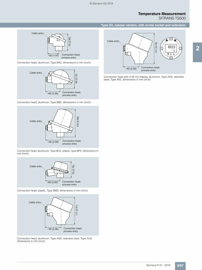
2/67Siemens FI 01 · 2018
Temperature MeasurementSITRANS TS500
Type 2G, tubular version, with screw socket and extension
2
Connection head, aluminum, Type BA0, dimensions in mm (inch)
Connection head, aluminum, Type BB0, dimensions in mm (inch)
Connection head, aluminum, Type BC0, plastic, type BP0, dimensions in mm (inch)
Connection head, plastic, Type BM0, dimensions in mm (inch)
Connection head, aluminum, Type AG0, stainless steel, Type AU0, dimensions in mm (inch)
Connection head with 4-20 mA display, aluminum, Type AH0, stainless steel, Type AV0, dimensions in mm (inch)
Cable entry
Connection head, process entry
~50 (1.97)
75 (2
.95)
Cable entry
Connection head, process entry
~65 (2.56)
80 (3
.15)
Cable entry
Connection head, process entry
~65 (2.56)
119
(4.6
9)
Connection head, process entry
Cable entry
~65 (2.56)
70 (2
.76)
Cable entry
Connection head, process entry
~65 (2.56)
117
(4.5
1)
Cable entry
Connection head, process entry~65 (2.56)
131
(5.1
6)
°C
© Siemens AG 2018

2/68 Siemens FI 01 · 2018
Temperature MeasurementSITRANS TS500
Type 2G, tubular version, with screw socket and extension
2
Selection and Ordering data Article No. Ord. Code
SITRANS TS500 7MC751-Tubular thermowell, minimal to medium stress, thermowell as per DIN 43722, Type 2G, screwed in, with extension
7 - 77777 - 7777
Head
Aluminum head, BA0, flange cover, Standard
A
Aluminum head, BB0, low hinged cover, screw connection
B
Aluminum head, BC0, high hinged cover, screw connection
C
Aluminum head, AG0, screw cover, suit-able for Ex d1)
1) Ex d in connection with Order code E032) Pt1000 versions are also available. To find these, please switch to Online
Configuration in the PIA Life Cycle Portal: www.siemens.com/pia-portal
G
Aluminum head, AH0, screw cover, suit-able for Ex d, display1)
H
Plastic head, BM0, screw cover M Plastic head, BP0high hinged cover, screw connection
P
Stainless steel head, AU0, screw cover, suitable for Ex d1)
U
Stainless steel head, AV0, screw cover,suitable for Ex d, display1)
V
Sensor2)
Please note: The accuracy class range can be lower than the measuring range. For more information, see page 2/17
Pt100, Basis, -50 ... +400 °C(-58 ... +752 °F)
A
Pt100, vibration resistant, -50 ... +400 °C (-58 ... +752 °F)
B
Pt100, expanded range, -196 ... +600 °C (-321 ... +1 112 °F)
C
Thermocouple Type K, -40 ... +1 000 °C(-40 ... +1 832 °F)
K
Thermocouple Type J, -40 ... +750 °C(-40 ... +1 382 °F)
J
Thermocouple Type N, -40 ... +1 000 °C(-40 ... +1 832 °F)
N
Sensor number/AccuracyCircuit Pt 100: 1 x 4-wire circuit or2 x 3-wire circuit, see "Measuring tech-nique: Connection types", page 2/19
Single, basic accuracy(Class 2/Class B)
1
Single, increased accuracy (Class 1/Class A)
2
Single, highest accuracy (Class AA)
3
Double, basic accuracy (Class 2/Class B)
5
Double, increased accuracy (Class 1/Class A)
6
Double, highest accuracy (Class AA) 7
Selection and Ordering data Order code
Further designs
Add "-Z" to Article No. and specify Order code.
Insertion length customer-specificSelect range, enter desired length in plain text (No entry = standard length)
Y44
Extension X length customer-specificSelect range, enter desired length in plain text (No entry = standard length)
Y45
OptionsAdd "-Z" to Article No. and add options, separate extensions with "+".
Built-in head transmitterMeasuring range to be set must be specified with plain text data "Y01".
SITRANS TH100, 4 ... 20 mA, Pt100 T10 SITRANS TH100 Ex i (ATEX), 4 ... 20 mA, Pt100 T11 SITRANS TH200, 4 ... 20 mA, Universal T20 SITRANS TH200 Ex i (ATEX), 4 ... 20 mA, Universal T21 SITRANS TH300, HART, Universal T30 SITRANS TH300 Ex i (ATEX), HART, Universal T31 SITRANS TH400 PA, Universal T40 SITRANS TH400 PA Ex i, Universal T41 SITRANS TH400 FF, Universal T45 SITRANS TH400 FF Ex i, Universal T46 Explosion protection Without explosion protection requirements
(Europe, Australia, New Zealand) E00
Intrinsic safety "i"/"IS1) according to ATEX and IECEx (Europe, Australia, New Zealand)
E01
Flameproof enclosure "d"/"XP; dust protection through housing "t"/"DIP"2) according to ATEX and IECEx (Europe, Australia, New Zealand)
E03
Non-sparking "nA"/"NI" according to ATEX and IECEx (Europe, Australia, New Zealand)
E04
Without explosion protection requirements (USA, Canada) Basis FM
E10
Intrinsic safety "i"/"IS"1) according to cFMus (USA, Canada)
E11
Flameproof enclosure "d"/"XP; dust protection through housing "t"/"DIP"2) according to cFMus (USA);NPT connections at the enclosure are mandatory
E13
Non-sparking "nA"/"NI" according to cFMus (USA, Canada)
E16
Without explosion protection requirements (USA, Canada)
E17
Intrinsic safety "i"/"IS"1) according to cCSAus(USA, Canada)
E18
Flameproof enclosure "d"/"XP; dust protection through housing "t"/"DIP"2) according to cCSAus (USA); other connections (M, G, R)
E21
Non-sparking "nA"/"NI" according to cCSAus(USA, Canada)
E23
Without explosion protection requirements (China) E54 Intrinsic safety "i"/"IS"1) according to NEPSI (China) E55 Flameproof enclosure "d"; dust protection through
housing "t"2) according to NEPSI (China) E56
Non-sparking "nA"/"NI" according to NEPSI (China) E57 Without explosion protection requirements (EAC) E80 Intrinsic safety "i"/"IS"1) according to EACEx (EAC) E81 Flameproof enclosure "d"/"XP; dust protection through
housing "t"/"DIP"2) according to EACEx (EAC) E82
Non-sparking "nA"/"NI" according to EACEx (EAC) E83 Marine approvals Det Norske Veritas Germanischer Lloyd (DNV GL) D01 Bureau Veritas (BV) D02 Lloyd’s Register of Shipping (LR) D04 American Bureau of Shipping (ABS) D05 Certificates and approvals EN 10204-3.1 Inspection certificate for materials
coming into contact with mediaC12
EN 10204-3.1 Inspection certificate for hydrostatic pressure test
C31
EN 10204-3.1 Inspection certificate for helium leak test C32 EN 10204-3.1 Inspection certificate for surface tear
testC33
EN 10204-3.1 Inspection certificate: visual, measure-ment and functional inspection
C34
EN 10204-2.1: Declaration of compliance with the order C35 ISO 9001 grease-free (cleaned for e.g. oxygen appli-
cations)C51
Selection and Ordering data Order code
© Siemens AG 2018

2/69Siemens FI 01 · 2018
Temperature MeasurementSITRANS TS500
Type 2G, tubular version, with screw socket and extension
2
1) Please select Ex i version of the optional transmitter.2) Only with connection heads code AG0, AH0, AU0, AV0, without cable
gland (please select non-Ex version of the optional transmitter).
You find ordering examples on page 2/40.Accessories, see page 2/237.
Designation, calibration Stainless steel TAG plate , enter lettering in plain text Y15 Plant calibration per 1 point, enter temperature in
plain textY33
Transmitter options Transmitter, enter complete setting in plain text
(Y01:+/-NNNN ... +/-NNNN C,F), marking on the device when Order code "Y15" is selected
Y01
Enter measuring point (max. 8 characters) in plain text
Y17
Transmitter, enter measuring point description (max. 16 characters) in plain text
Y23
Transmitter, enter measuring point text (max. 32 characters) in plain text
Y24
Transmitter, enter bus address in plain text Y25 Transmitter, fail-safe value 3.6 mA
(instead of 22.8 mA)U36
Transmitter with a SIL 2 conformity C20Transmitter with a SIL 2/3 conformity C23Transmitter test protocol (5 points) C11
Further options
Connection form, flying leads (for the direct transmit-ter assembly, delivery without screws and springs)
G01
M12 device plug (in combination with 1x Pt100 and/or transmitter, Non-Ex and intrinsically safe, max. IP65/67)
G12
Han 7D device plug (Non Ex and intrinsically safe, without mating connector max. IP65/67)
G13
Connection head with ½" NPT thread without cable gland, for AU0 and AH0 only IP66
G20
with outer earth screw for heads AG0, AH0, AU0 and AV0
A02
with inner earth screw for heads BC0, AG0, AH0, AU0 and AV0
A03
Option not found? Handling number special version Y99
Selection and Ordering data Order code
© Siemens AG 2018

2/70 Siemens FI 01 · 2018
Temperature MeasurementSITRANS TS500
Type 2F, tubular version, with flange and extension
2
■ Dimensional drawings
SITRANS TS500, temperature sensors for vessels and pipelines, tubular version for minimal to medium stress, thermowell as per DIN 43722, Type 2F, with flange, with extension, dimensions in mm (inch)
H1 Type Axx = 41 (1.61)Type Bxx = 26 (1.02)
Ød Measuring insert outer diameter (6 (0.24)) ØD Process connection outer diameterØD3 Thermowell internal diameterH Head height
B Measuring insert length
N Nominal lengthU Insertion lengthX Extension length
Cable entry
Ød
ØD3
HN
X
B =
N +
H1
ØD
U1
© Siemens AG 2018

2/71Siemens FI 01 · 2018
Temperature MeasurementSITRANS TS500
Type 2F, tubular version, with flange and extension
2
Additional configurations on page after next page!
You find ordering examples on page 2/40!
Selection and Ordering data Article No. Ord. Code
SITRANS TS500 7MC751-Tubular thermowell, minimal to medium stress, thermowell as per DIN 43722, Type 2F, with flange, with extension
7 - 77777 - 7777 777
Click on the Article No. for the online configuration in the PIA Life Cycle Portal.
Material, in contact with media 316Ti (1.4571) 1 316L (1.4404 or 1.4435) 2
Process connection
Flange EN, DN25 PN10 ... 40 B1 2 A Flange ASME, 1"RF150 2 E
Flange ASME, 1"RF300 2 F Flange ASME, 1.5"RF150 2 G Flange ASME, 1.5"RF300 2 H
Thermowell form
2F, 9 mm (0.35 inch) A 2F, 12 mm (0.47 inch) B Insertion U standard
225 mm (8.86 inch) 1 1 315 mm (12.40 inch) 1 5 465 mm (18.31 inch) 2 6
Insertion length U customer-specificenter customer specific length with Y44, see page 2/73 Order codes
80 ... 100 mm (3.15 ... 3.94 inch) Initial: 100 mm (3.94 inch)
0 1
101 ... 120 mm (3.98 ... 4.72 inch) Initial: 120 mm (4.72 inch)
0 2
121 ... 140 mm (4.76 ... 5.51 inch) Initial: 140 mm (5.51 inch)
0 3
141 ... 160 mm (5.55 ... 6.30 inch) Initial: 160 mm (6.30 inch)
0 4
161 ... 180 mm (6.34 ... 7.09 inch) Initial: 180 mm (7.09 inch)
0 5
181 ... 200 mm (7.13 ... 7.87 inch) Initial: 200 mm (7.87 inch)
0 6
201 ... 220 mm (7.91 ... 8.66 inch) Initial: 220 mm (8.66 inch)
0 7
221…240 mm (8.70 ... 9.45 inch) Initial: 225 mm (8.86 inch)
1 1
241…260 mm (9.49 ... 10.24 inch) Initial: 250 mm (9.84 inch)
1 2
261…280 mm (10.28 ...11.02 inch) Initial: 280 mm (11.02 inch)
1 3
281…300 mm (11.06 ... 11.81 inch) Initial: 285 mm 11.22 inch)
1 4
301…320 mm (11.85 ... 13.00 inch) Initial: 315 mm (12.40 inch)
1 5
321…340 mm (12.64 ... 13.39 inch) Initial: 340 mm (13.39 inch)
1 6
341…360 mm (13.43 ... 14.17 inch) Initial: 360 mm (14.17 inch)
2 0
361…380 mm (14.21 ... 14.96 inch) Initial: 380 mm (14.96 inch)
2 1
381…400 mm (14.99 ... 15.75 inch) Initial: 400 mm (15.75 inch)
2 2
401…420 mm (15.79 ... 16.54 inch) Initial: 420 mm (16.54 inch)
2 3
421…440 mm (16.57 ... 17.32 inch) Initial: 440 mm (17.32 inch)
2 4
441…460 mm (17.36 ... 18.11 inch) Initial: 460 mm (18.11 inch)
2 5
461…480 mm (18.15 ... 18.90 inch) Initial: 465 mm (18.30 inch)
2 6
481…500 mm (18.94 ... 19.69 inch) Initial: 500 mm (19.69 inch)
2 7
501…550 mm (19.72 ... 21.65 inch) Initial: 510 mm (20.08 inch)
3 1
551…600 mm (21.69 ... 23.62 inch) Initial: 600 mm (23.62 inch)
3 2
601…650 mm (23.66 ... 25.59 inch) Initial: 650 mm (25.59 inch)
3 3
651…700 mm (25.63 ... 27.56 inch) Initial: 700 mm (27.56 inch)
3 4
701…750 mm (27.60 ... 29.53 inch) Initial: 750 mm (29.53 inch)
3 5
751…800 mm (29.57 ... 31.50 inch) Initial: 800 mm (31.50 inch)
3 6
801…850 mm (31.54 ... 33.46 inch) Initial: 850 mm (33.46 inch)
3 7
851…900 mm (33.50 ... 35.43 inch) Initial: 900 mm (35.43 inch)
4 1
901…950 mm (35.47 ... 37.40 inch) Initial: 950 mm (37.40 inch)
4 2
951…1 000 mm (37.44 ... 39.37 inch) Initial: 1 000 mm (39.37 inch)
4 3
1 001…1 100 mm (39.41 ... 43.31 inch) Initial: 1 100 mm (43.31 inch)
4 4
1 101…1 200 mm (43.35 ... 47.24 inch) Initial: 1 200 mm (47.24 inch)
4 5
1 201…1 300 mm (47.28 ... 51.18 inch) Initial: 1 300 mm (51.18 inch)
4 6
1 301…1 400 mm (51.22 ... 55.12 inch) Initial: 1 400 mm (55.12 inch)
4 7
1 401…1 500 mm (55.16 ... 59.05 inch) Initial: 1 500 mm (59.05 inch)
5 1
Extension X
Standard length for Type 2F DIN 43772 (X=64 mm (2.52 inch))
1
Extension length X - customer specificenter customer specific length with Y45, see page 2/73 Order codes
45 ...150 mm (1.77 ... 5.91 inch)Initial: 150 mm (5.91 inch)
9 N 1 D
151 ... 300 mm (5.95 ... 11.81 inch)Initial: 300 mm (11.81 inch)
9 N 2 D
301 ... 450 mm (11.85 ... 17.72 inch)Initial: 450 mm (17.72 inch)
9 N 3 D
Selection and Ordering data Article No. Ord. Code
SITRANS TS500 7MC751-Tubular thermowell, minimal to medium stress, thermowell as per DIN 43722, Type 2F, with flange, with extension
7 - 77777 - 7777 777
© Siemens AG 2018

2/72 Siemens FI 01 · 2018
Temperature MeasurementSITRANS TS500
Type 2F, tubular version, with flange and extension
2
Connection head, aluminum, Type BA0, dimensions in mm (inch)
Connection head, aluminum, Type BB0, dimensions in mm (inch)
Connection head, aluminum, Type BC0, plastic, type BP0, dimensions in mm (inch)
Connection head, plastic, Type BM0, dimensions in mm (inch)
Connection head, aluminum, Type AG0, stainless steel, Type AU0, dimensions in mm (inch)
Connection head with 4-20 mA display, aluminum, Type AH0, stainless steel, Type AV0, dimensions in mm (inch)
Cable entry
Connection head, process entry
~50 (1.97)
75 (2
.95)
Cable entry
Connection head, process entry
~65 (2.56)
80 (3
.15)
Cable entry
Connection head, process entry
~65 (2.56)
119
(4.6
9)
Connection head, process entry
Cable entry
~65 (2.56)
70 (2
.76)
Cable entry
Connection head, process entry
~65 (2.56)
117
(4.5
1)
Cable entry
Connection head, process entry~65 (2.56)
131
(5.1
6)
°C
© Siemens AG 2018

2/73Siemens FI 01 · 2018
Temperature MeasurementSITRANS TS500
Type 2F, tubular version, with flange and extension
2
Selection and Ordering data Article No.
SITRANS TS500 7MC751-
Tubular thermowell, minimal to medium stress, thermowell as per DIN 43722, Type 2F, with flange, with extension
7 - 77777 - 7777 777
Head
Aluminum head, BA0, flange cover, Standard
A
Aluminum head, BB0, low hinged cover, screw connection
B
Aluminum head, BC0, high hinged cover, screw connection
C
Aluminum head, AG0, screw cover, suit-able for Ex d1)
1) Ex d in connection with Order code E032) Pt1000 versions are also available. To find these, please switch to Online
Configuration in the PIA Life Cycle Portal: www.siemens.com/pia-portal
G
Aluminum head, AH0, screw cover, suit-able for Ex d, display1)
H
Plastic head, BM0, screw cover M Plastic head, BP0high hinged cover, screw connection
P
Stainless steel head, AU0, screw cover, suitable for Ex d1)
U
Stainless steel head, AV0, screw cover, suitable for Ex d, display1)
V
Sensor2)
Please note: The accuracy class range can be lower than the measuring range. For more information, see page 2/17
Pt100, Basis, -50 ... +400 °C(-58 ... +752 °F)
A
Pt100, vibration resistant, -50 ... +400 °C (-58 ... +752 °F)
B
Pt100, expanded range, -196 ... +600 °C (-321 ... +1 112 °F)
C
Thermocouple Type K, -40 ... +1 000 °C(-40 ... +1 832 °F)
K
Thermocouple Type J, -40 ... +750 °C(-40 ... +1 382 °F)
J
Thermocouple Type N, -40 ... +1 000 °C(-40 ... +1 832 °F)
N
Sensor number/AccuracyCircuit Pt 100: 1 x 4-wire circuit or2 x 3-wire circuit, see "Measuring tech-nique: Connection types", page 2/19
Single, basic accuracy(Class 2/Class B)
1
Single, increased accuracy (Class 1/Class A)
2
Single, highest accuracy (Class AA) 3 Double, basic accuracy (Class 2/Class B) 5 Double, increased accuracy (Class 1/Class A)
6
Double, highest accuracy (Class AA) 7
Selection and Ordering data Order code
Further designs
Add "-Z" to Article No. and specify Order code.
Insertionlength customer-specificSelect range, enter desired length in plain text (No entry = standard length)
Y44
Extension X length customer-specificSelect range, enter desired length in plain text (No entry = standard length)
Y45
OptionsAdd "-Z" to Article No. and add options, separate extensions with "+".
Built-in head transmitterMeasuring range to be set must be specified with plain text data "Y01".
SITRANS TH100, 4 ... 20 mA, Pt100 T10 SITRANS TH100 Ex i (ATEX), 4 ... 20 mA, Pt100 T11 SITRANS TH200, 4 ... 20 mA, Universal T20 SITRANS TH200 Ex i (ATEX), 4 ... 20 mA, Universal T21 SITRANS TH300, HART, Universal T30 SITRANS TH300 Ex i (ATEX), HART, Universal T31 SITRANS TH400 PA, Universal T40 SITRANS TH400 PA Ex i, Universal T41 SITRANS TH400 FF, Universal T45 SITRANS TH400 FF Ex i, Universal T46 Explosion protection Without explosion protection requirements
(Europe, Australia, New Zealand) E00
Intrinsic safety "i"/"IS1) according to ATEX and IECEx (Europe, Australia, New Zealand)
E01
Flameproof enclosure "d"/"XP; dust protection through housing "t"/"DIP"2) according to ATEX and IECEx (Europe, Australia, New Zealand)
E03
Non-sparking "nA"/"NI" according to ATEX and IECEx (Europe, Australia, New Zealand)
E04
Without explosion protection requirements(USA, Canada) Basis FM
E10
Intrinsic safety "i"/"IS"1) according to cFMus (USA,Canada)
E11
Flameproof enclosure "d"/"XP; dust protection through housing "t"/"DIP"2) according to cFMus (USA);NPT connections at the enclosure are mandatory
E13
Non-sparking "nA"/"NI" according to cFMus (USA,Canada)
E16
Without explosion protection requirements (USA, Canada)
E17
Intrinsic safety "i"/"IS"1) according to cCSAus(USA, Canada)
E18
Flameproof enclosure "d"/"XP; dust protection through housing "t"/"DIP"2) according to cCSAus (USA); other connections (M, G, R)
E21
Non-sparking "nA"/"NI" according to cCSAus(USA, Canada)
E23
Without explosion protection requirements (China) E54 Intrinsic safety "i"/"IS"1) according to NEPSI (China) E55 Flameproof enclosure "d"; dust protection through
housing "t"2) according to NEPSI (China) E56
Non-sparking "nA"/"NI" according to NEPSI (China) E57 Without explosion protection requirements (EAC) E80 Intrinsic safety "i"/"IS"1) according to EACEx (EAC) E81 Flameproof enclosure "d"/"XP; dust protection through
housing "t"/"DIP"2) according to EACEx (EAC) E82
Non-sparking "nA"/"NI" according to EACEx (EAC) E83 Marine approvals
Det Norske Veritas Germanischer Lloyd (DNV GL) D01 Bureau Veritas (BV) D02 Lloyd’s Register of Shipping (LR) D04 American Bureau of Shipping (ABS) D05 Certificates and approvals EN 10204-3.1 Inspection certificate for materials
coming into contact with mediaC12
EN 10204-3.1 Inspection certificate for hydrostatic pressure test
C31
EN 10204-3.1 Inspection certificate for helium leak test C32 EN 10204-3.1 Inspection certificate for surface tear test C33 EN 10204-3.1 Inspection certificate: visual, measure-
ment and functional inspectionC34
EN 10204-2.1: Declaration of compliance with the order C35 ISO 9001 grease-free (cleaned for e.g. oxygen appli-
cations)C51
Selection and Ordering data Order code
© Siemens AG 2018

2/74 Siemens FI 01 · 2018
Temperature MeasurementSITRANS TS500
Type 2F, tubular version, with flange and extension
2
1) Please select Ex i version of the optional transmitter.2) Only with connection heads code AG0, AH0, AU0, AV0, without cable
gland (please select non-Ex version of the optional transmitter).
You find ordering examples on page 2/40.Accessories, see page 2/237.
Designation, calibration Stainless steel TAG plate , enter lettering in plain text Y15 Plant calibration per 1 point, enter temperature in
plain textY33
Transmitter options Transmitter, enter complete setting in plain text
(Y01:+/-NNNN ... +/-NNNN C,F), marking on the device when Order code "Y15" is selected
Y01
Enter measuring point (max. 8 characters) in plain text
Y17
Transmitter, enter measuring point description (max. 16 characters) in plain text
Y23
Transmitter, enter measuring point text (max. 32 characters) in plain text
Y24
Transmitter, enter bus address in plain text Y25 Transmitter, fail-safe value 3.6 mA
(instead of 22.8 mA)U36
Transmitter with a SIL 2 conformity C20Transmitter with a SIL 2/3 conformity C23Transmitter test protocol (5 points) C11
Further options
Connection form, flying leads (for the direct transmitter assembly, delivery without screws and springs)
G01
M12 device plug (in combination with 1x Pt100 and/or transmitter, Non-Ex and intrinsically safe, max. IP65/67)
G12
Han 7D device plug (Non Ex and intrinsically safe, without mating connector max. IP65/67)
G13
Connection head with ½" NPT thread without cable gland, for AU0 and AH0 only IP66
G20
with outer earth screw for heads AG0, AH0, AU0 and AV0
A02
with inner earth screw for heads BC0, AG0, AH0, AU0 and AV0
A03
Option not found? Handling number special version Y99
Selection and Ordering data Order code
© Siemens AG 2018

2/75Siemens FI 01 · 2018
Temperature MeasurementSITRANS TS500
Type 3, tubular quick, without process connection
2
■ Dimensional drawings
SITRANS TS500, temperature sensors for vessel and pipings, tubular version for minimum to medium stress, without process connection, with-out extension, plug-in or use with moveable compression fitting, dimen-sion in mm (inch)
Ød Measuring insert outer diameter (6 (0.24))ØD Process connection outer diameterØD1 Tip internal diameterØD2 Tip outer diameterØD3 Thermowell diameterH Head height
B Measuring insert length
N Nominal lengthP Space for process connection
Cable entry
H1 Type Axx> 41 (1.61)Type Bxx> 26 (1.02)
BE
urop
ean =
N +
H1 - 3
Ød
ØD3
HN
ØD2
35 (1
.34)
50 (1
.97)
ØD
ØD1
P1
© Siemens AG 2018

2/76 Siemens FI 01 · 2018
Temperature MeasurementSITRANS TS500
Type 3, tubular quick, without process connection
2
Additional configurations on page after next page!
You find ordering examples on page 2/40!
Selection and Ordering data Article No.
SITRANS TS500 7MC751-
Tubular version for minimal to medium stress, thermowell per DIN 43722, Type 3, without process connection, improved response time, plug-in or use with moveable compression fittings
7 - 77777 - 7777
Click on the Article No. for the online configu-ration in the PIA Life Cycle Portal.
Material, in contact with media
316Ti (1.4571) 1 316L (1.4404 or 1.4435) 2 Process connection
Without process connection (for compression joints) N=U
0 N
Thermowell form
3, 12/9 mm (0.47/0.35 inch) K Insertion length U (=N), Standard
160 mm (6.3 inch) 0 4 220 mm (8.66 inch) 0 7 280 mm (11.02 inch) 1 3 Insertion length U (=N), customer-specific
enter customer specific length with Y44, see page 2/78 Order codes
121 ... 140 mm (4.76 ... 5.51 inch)Initial: 140 mm (5.51 inch)
0 3
141 ... 160 mm (5.55 ... 6.30 inch)Initial: 160 mm (6.3 inch)
0 4
161 ... 180 mm (6.34 ... 7.09 inch)Initial: 180 mm (7.09 inch)
0 5
181 ... 200 mm (7.13 ... 7.87 inch)Initial: 200 mm (7.87 inch)
0 6
201 ... 220 mm (7.91 ... 8.66 inch)Initial: 220 mm (8.66 inch)
0 7
221 ... 240 mm (8.7 ... 9.45 inch)Initial: 225 mm (8.86 inch)
1 1
241 ... 260 mm (9.48 ... 10.24 inch)Initial: 250 mm (9.84 inch)
1 2
261 ... 280 mm (10.28 ... 11.02 inch)Initial: 280 mm (11.02 inch)
1 3
281 ... 300 mm (11.02 ... 11.81 inch)Initial: 285 mm (11.22 inch)
1 4
301 ... 320 mm (11.85 ... 12.6 inch)Initial: 315 mm (12.4 inch)
1 5
321 ... 340 mm (12.64 ... 13.39 inch)Initial: 340 mm (13.39 inch)
1 6
341 ... 360 mm (13.43 ... 14.17 inch)Initial: 360 mm (14.17 inch)
2 0
361 ... 380 mm (14.21 ... 14.96 inch)Initial: 380 mm (14.96 inch)
2 1
381 ... 400 mm (15 ... 15.75 inch)Initial: 400 mm (15.75 inch)
2 2
401 ... 420 mm (15.79 ... 16.54 inch)Initial: 420 mm (16.54 inch)
2 3
421 ... 440 mm (16.57 ... 17.32 inch)Initial: 440 mm (17.32 inch)
2 4
441 ... 460 mm (17.36 ... 18.11 inch)Initial: 460 mm (18.11 inch)
2 5
461 ... 480 mm (18.15 ... 18.90 inch)Initial: 465 mm (18.30 inch)
2 6
481 ... 500 mm (18.94 ... 19.68 inch)Initial: 500 mm (19.68 inch)
2 7
501 ... 550 mm (19.72 ... 21.65 inch)Initial: 510 mm (20.08 inch)
3 1
551 ... 600 mm (21.69 ... 23.62 inch)Initial: 600 mm (23.62 inch)
3 2
601 ... 650 mm (23.66 ... 25.59 inch)Initial: 650 mm (25.59 inch)
3 3
651 ... 700 mm (25.63 ... 27.56 inch)Initial: 700 mm (27.56 inch)
3 4
701 ... 750 mm (27.6 ... 29.53 inch)Initial: 750 mm (29.53 inch)
3 5
751 ... 800 mm (29.57 ... 31.50 inch)Initial: 800 mm (31.50 inch)
3 6
801 ... 850 mm (31.53 ... 33.46 inch)Initial: 850 mm (33.46 inch)
3 7
851 ... 900 mm (33.50 ... 35.43 inch)Initial: 900 mm (35.43 inch)
4 1
901 ... 950 mm (35.47 ... 37.40 inch)Initial: 950 mm (37.40 inch)
4 2
951 ... 1 000 mm (37.44 ... 39.37 inch)Initial: 1 000 mm (39.37 inch)
4 3
1 001 ... 1 100 mm (39.41 ... 43.31 inch)Initial: 1 100 mm (43.31 inch)
4 4
Extension
Standard length for Type 2 as per DIN 43722 (without extension N=U)
0
Selection and Ordering data Article No.
SITRANS TS500 7MC751-
Tubular version for minimal to medium stress, thermowell per DIN 43722, Type 3, without process connection, improved response time, plug-in or use with moveable compression fittings
7 - 77777 - 7777
© Siemens AG 2018

2/77Siemens FI 01 · 2018
Temperature MeasurementSITRANS TS500
Type 3, tubular quick, without process connection
2
Connection head, aluminum, Type BA0, dimensions in mm (inch)
Connection head, aluminum, Type BB0, dimensions in mm (inch)
Connection head, aluminum, Type BC0, plastic, type BP0, dimensions in mm (inch)
Connection head, plastic, Type BM0, dimensions in mm (inch)
Connection head, aluminum, Type AG0, stainless steel, Type AU0, dimensions in mm (inch)
Connection head with 4-20 mA display, aluminum, Type AH0, stainless steel, Type AV0, dimensions in mm (inch)
Cable entry
Connection head, process entry
~50 (1.97)
75 (2
.95)
Cable entry
Connection head, process entry
~65 (2.56)
80 (3
.15)
Cable entry
Connection head, process entry
~65 (2.56)
119
(4.6
9)
Connection head, process entry
Cable entry
~65 (2.56)
70 (2
.76)
Cable entry
Connection head, process entry
~65 (2.56)
117
(4.5
1)
Cable entry
Connection head, process entry~65 (2.56)
131
(5.1
6)
°C
© Siemens AG 2018

2/78 Siemens FI 01 · 2018
Temperature MeasurementSITRANS TS500
Type 3, tubular quick, without process connection
2
Selection and Ordering data Article No.
SITRANS TS500 7MC751-
Tubular version for minimal to medium stress, thermowell as per DIN 43722, Type 3, without process connection, improved response time, plug-in or use with moveable compression fittings
7 - 77777 - 7777
Head Aluminum head, BA0, flange cover,
Standard A
Aluminum head, BB0, low hinged cover, screw connection
B
Aluminum head, BC0, high hinged cover, screw connection
C
Aluminum head, AG0, screw cover, suit-able for Ex d1)
1) Ex d in connection with Order code E032) Pt1000 versions are also available. To find these, please switch to Online
Configuration in the PIA Life Cycle Portal: www.siemens.com/pia-portal
G
Aluminum head, AH0, screw cover, suit-able for Ex d, display1)
H
Plastic head, BM0, screw cover M Plastic head, BP0high hinged cover,
screw connection P
Stainless steel head, AU0, screw cover, Ex d1)
U
Stainless steel head, AV0, screw cover, suitable for Ex d, display1)
V
Sensor2)
Please note: The accuracy class range can be lower than the measuring range. For more information, see page 2/17
Pt100, basis, -50 ... +400 °C(-58 ... +752 °F)
A
Pt100, vibration-resistant, -50 ... +400 °C (-58 ... +752 °F)
B
Pt100, expanded range, -196 ... +600 °C (-321 ... +1 112 °F)
C
Thermocouple Type J, only class 2, -40 ... +750 °C (-40 ... +1 382 °F)
J
Thermocouple Type K, -40 .. . +1 000 °C (-40 ... +1 832 °F)
K
Thermocouple Type N, -40 ... +1 000 °C (-40 ... +1 832 °F)
N
Sensor number/AccuracyCircuit Pt 100: 1 x 4-wire circuit or2 x 3-wire circuit, see "Measuring tech-nique: Connection types", page 2/19
Single, basic accuracy(Class 2/Class B)
1
Single, increased accuracy(Class 1/Class A)
2
Single, highest accuracy (Class AA) 3 Double, basic accuracy
(Class 2/Class B) 5
Double, increased accuracy (Class 1/Class A)
6
Double, highest accuracy (Class AA) 7
Selection and Ordering data Order code
Further designs
Add "-Z" to Article No. and specify Order code.
Insertion length customer-specificSelect range, enter desired length in plain text (No entry = standard length)
Y44
OptionsAdd "-Z" to Article No. and add options, separate extensions with "+".
Built-in head transmitterMeasuring range to be set must be specified with plain text data "Y01".
SITRANS TH100, 4 ... 20 mA, Pt100 T10 SITRANS TH100 Ex i (ATEX), 4 ... 20 mA, Pt100 T11 SITRANS TH200, 4 ... 20 mA, Universal T20 SITRANS TH200 Ex i (ATEX), 4 ... 20 mA, Universal T21 SITRANS TH300, HART, Universal T30 SITRANS TH300 Ex i (ATEX), HART, Universal T31 SITRANS TH400 PA, Universal T40 SITRANS TH400 PA Ex i, Universal T41 SITRANS TH400 FF, Universal T45 SITRANS TH400 FF Ex i, Universal T46 Explosion protection
Without explosion protection requirements(Europe, Australia, New Zealand)
E00
Intrinsic safety "i"/"IS1) according to ATEX and IECEx (Europe, Australia, New Zealand)
E01
Flameproof enclosure "d"/"XP; dust protection through housing "t"/"DIP"2) according to ATEX and IECEx (Europe, Australia, New Zealand)
E03
Non-sparking "nA"/"NI" according to ATEX and IECEx (Europe, Australia, New Zealand)
E04
Without explosion protection requirements (USA, Canada) Basis FM
E10
Intrinsic safety "i"/"IS"1) according to cFMus (USA, Canada)
E11
Flameproof enclosure "d"/"XP; dust protection through housing "t"/"DIP"2) according to cFMus (USA);NPT connections at the enclosure are mandatory
E13
Non-sparking "nA"/"NI" according to cFMus (USA, Canada)
E16
Without explosion protection requirements (USA, Canada)
E17
Intrinsic safety "i"/"IS"1) according to cCSAus(USA, Canada)
E18
Flameproof enclosure "d"/"XP; dust protection through housing "t"/"DIP"2) according to cCSAus (USA); other connections (M, G, R)
E21
Non-sparking "nA"/"NI" according to cCSAus(USA, Canada)
E23
Without explosion protection requirements (China) E54 Intrinsic safety "i"/"IS"1) according to NEPSI (China) E55 Flameproof enclosure "d"; dust protection through
housing "t"2) according to NEPSI (China) E56
Non-sparking "nA"/"NI" according to NEPSI (China) E57 Without explosion protection requirements (EAC) E80 Intrinsic safety "i"/"IS"1) according to EACEx (EAC) E81 Flameproof enclosure "d"/"XP; dust protection through
housing "t"/"DIP"2) according to EACEx (EAC) E82
Non-sparking "nA"/"NI" according to EACEx (EAC) E83 Marine approvals Det Norske Veritas Germanischer Lloyd (DNV GL) D01 Bureau Veritas (BV) D02 Lloyd’s Register of Shipping (LR) D04 American Bureau of Shipping (ABS) D05 Certificates and approvals EN 10204-3.1 Inspection certificate for materials
coming into contact with mediaC12
EN 10204-3.1 Inspection certificate for hydrostatic pressure test
C31
EN 10204-3.1 Inspection certificate for helium leak test C32 EN 10204-3.1 Inspection certificate for surface tear
testC33
EN 10204-3.1 Inspection certificate: visual, measure-ment and functional inspection
C34
EN 10204-2.1: Declaration of compliance with the order C35 ISO 9001 grease-free (cleaned for e.g. oxygen appli-
cations)C51
Selection and Ordering data Order code
© Siemens AG 2018

2/79Siemens FI 01 · 2018
Temperature MeasurementSITRANS TS500
Type 3, tubular quick, without process connection
2
1) Please select Ex i version of the optional transmitter.2) Only with connection heads code AG0, AH0, AU0, AV0, without cable
gland (please select non-Ex version of the optional transmitter).
You find ordering examples on page 2/40.Accessories, see page 2/237.
Designation, calibration Stainless steel TAG plate , enter lettering in plain text Y15 Plant calibration per 1 point, enter temperature in
plain textY33
Transmitter options Transmitter, enter complete setting in plain text
(Y01:+/-NNNN ... +/-NNNN C,F), marking on the device when Order code "Y15" is selected
Y01
Enter measuring point (max. 8 characters) in plain text
Y17
Transmitter, enter measuring point description (max. 16 characters) in plain text
Y23
Transmitter, enter measuring point text (max. 32 characters) in plain text
Y24
Transmitter, enter bus address in plain text Y25 Transmitter, fail-safe value 3.6 mA
(instead of 22.8 mA)U36
Transmitter with a SIL 2 conformity C20Transmitter with a SIL 2/3 conformity C23Transmitter test protocol (5 points) C11
Further options Connection form, flying leads (for the direct transmit-
ter assembly, delivery without screws and springs)G01
M12 device plug (in combination with 1x Pt100 and/or transmitter, Non-Ex and intrinsically safe, max. IP65/67)
G12
Han 7D device plug (Non Ex and intrinsically safe, without mating connector max. IP65/67)
G13
Connection head with ½" NPT thread without cable gland, for AU0 and AH0 only IP66
G20
with outer earth screw for heads AG0, AH0, AU0 and AV0
A02
with inner earth screw for heads BC0, AG0, AH0, AU0 and AV0
A03
Compression joint G½", enclosed A31 Compression joint NPT½", enclosed A32
Option not found? Handling number special version Y99
Selection and Ordering data Order code
© Siemens AG 2018

2/80 Siemens FI 01 · 2018
Temperature MeasurementSITRANS TS500
Type 3G, tubular quick, with screw socket and extension
2
■ Dimensional drawings
SITRANS TS500, temperature sensors for vessels and pipelines, tubular version for minimal to medium stress, thermowell as per DIN 43722, Type 3G, screwed in, with extension.For dimensions for the screw depth see page 2/12, dimensions in mm (inch).
Tapered process connection, dimensions in mm (inch)
H1 Type Axx = 41 (1.61)Type Bxx = 26 (1.02)
Ød Measuring insert outer diameter (6 (0.24)) ØD Process connection outer diameterØD1 Tip internal diameterØD2 Tip outer diameterØD3 Thermowell internal diameterE Process connection, thread sizeH Head height
B Measuring insert length
K1 Screw depthN Nominal lengthU Insertion lengthX Extension length
Cable entry
BE
urop
ean =
N +
H1 - 3
ØdØD3
HN
X
ØD2
UK
1
E
35 (1
.38)
50 (1
.97)
ØD
ØD1
1
K2
E
X
U
ØD
K1
© Siemens AG 2018

2/81Siemens FI 01 · 2018
Temperature MeasurementSITRANS TS500
Type 3G, tubular quick, with screw socket and extension
2
Additional configurations on page after next page!
You find ordering examples on page 2/40!
Selection and Ordering data Article No. Ord. Code
SITRANS TS500 7MC751-Tubular thermowell, minimal to medium stress, thermowell as per DIN 43722, Type 3G, screwed in, with extension
7 - 77777 - 7777 777
Click on the Article No. for the online configuration in the PIA Life Cycle Portal.
Material, in contact with media 316Ti (1.4571) 1 316L (1.4404 or 1.4435) 2
Process connection
Cylindrical: G½" inch (½" BSPP) 1 C Cylindrical: G1" inch (1" BSPP) 1 E Tapered: NPT½" 1 J
Thermowell form
3G, 12/9 mm (0.47/0.35 inch) K
Insertion length U standard
160 mm (6.30 inch) 0 4 220 mm (8.66 inch) 0 7 280 mm (11.02 inch) 1 3
Insertion length U customer-specificenter customer specific length with Y44, see page 2/83 Order codes
121 ... 140 mm (4.76 ... 5.51 inch) Initial: 140 mm (5.51 inch)
0 3
141 ... 160 mm (5.55 ... 6.30 inch) Initial: 160 mm (6.30 inch)
0 4
161 ... 180 mm (6.34 ... 7.09 inch) Initial: 180 mm (7.09 inch)
0 5
181 ... 200 mm (7.13 ... 7.87 inch) Initial: 200 mm (7.87 inch)
0 6
201 ... 220 mm (7.91 ... 8.66 inch) Initial: 220 mm (8.66 inch)
0 7
221…240 mm (8.70 ... 9.45 inch) Initial: 225 mm (8.86 inch)
1 1
241…260 mm (9.49 ... 10.24 inch) Initial: 250 mm (9.84 inch)
1 2
261…280 mm (10.28 ...11.02 inch) Initial: 280 mm (11.02 inch)
1 3
281…300 mm (11.06 ... 11.81 inch) Initial: 285 mm 11.22 inch)
1 4
301…320 mm (11.85 ... 13.00 inch) Initial: 315 mm (12.40 inch)
1 5
321…340 mm (12.64 ... 13.39 inch) Initial: 340 mm (13.39 inch)
1 6
341…360 mm (13.43 ... 14.17 inch) Initial: 360 mm (14.17 inch)
2 0
361…380 mm (14.21 ... 14.96 inch) Initial: 380 mm (14.96 inch)
2 1
381…400 mm (14.99 ... 15.75 inch) Initial: 400 mm (15.75 inch)
2 2
401…420 mm (15.79 ... 16.54 inch) Initial: 420 mm (16.54 inch)
2 3
421…440 mm (16.57 ... 17.32 inch) Initial: 440 mm (17.32 inch)
2 4
441…460 mm (17.36 ... 18.11 inch) Initial: 460 mm (18.11 inch)
2 5
461…480 mm (18.15 ... 18.90 inch) Initial: 465 mm (18.30 inch)
2 6
481…500 mm (18.94 ... 19.69 inch) Initial: 500 mm (19.69 inch)
2 7
501 ... 550 mm (19.72 ... 21.65 inch)Initial: 510 mm (20.08 inch)
3 1
551 ... 600 mm (21.69 ... 23.62 inch)Initial: 600 mm (23.62 inch)
3 2
601 ... 650 mm (23.66 ... 25.59 inch)Initial: 650 mm (25.59 inch)
3 3
651 ... 700 mm (25.63 ... 27.56 inch)Initial: 700 mm (27.56 inch)
3 4
701 ... 750 mm (27.6 ... 29.53 inch)Initial: 750 mm (29.53 inch)
3 5
751 ... 800 mm (29.57 ... 31.50 inch)Initial: 800 mm (31.50 inch)
3 6
801 ... 850 mm (31.53 ... 33.46 inch)Initial: 850 mm (33.46 inch)
3 7
851 ... 900 mm (33.50 ... 35.43 inch)Initial: 900 mm (35.43 inch)
4 1
901 ... 950 mm (35.47 ... 37.40 inch)Initial: 950 mm (37.40 inch)
4 2
951 ... 1 000 mm (37.44 ... 39.37 inch)Initial: 1 000 mm (39.37 inch)
4 3
Extension X
Standard length for Type 2G DIN 43772 (X=131 mm (5.08 inch))
1
Extension length - customer specificenter customer specific length with Y45, see page 2/83 Order codes
45 ...150 mm (1.77 ... 5.91 inch)Initial: 150 mm (5.91 inch)
9 N 1 D
151 ... 300 mm (5.95 ... 11.81 inch)Initial: 300 mm (11.81 inch)
9 N 2 D
Selection and Ordering data Article No. Ord. Code
SITRANS TS500 7MC751-Tubular thermowell, minimal to medium stress, thermowell as per DIN 43722, Type 3G, screwed in, with extension
7 - 77777 - 7777 777
© Siemens AG 2018
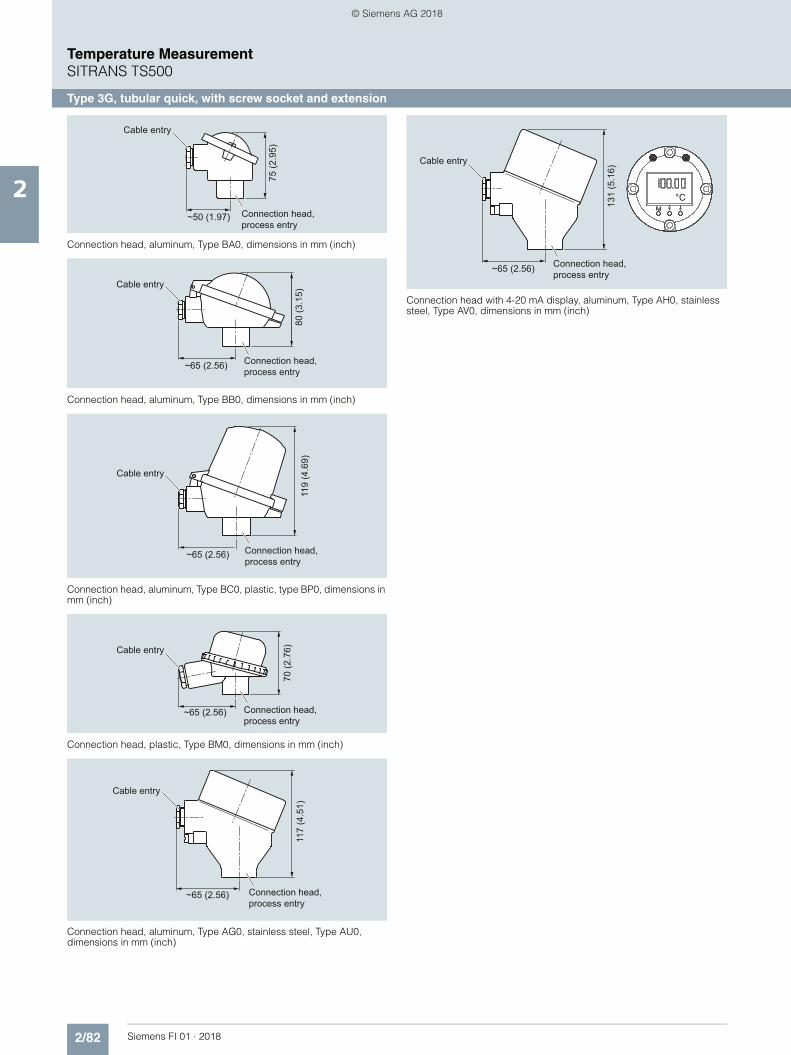
2/82 Siemens FI 01 · 2018
Temperature MeasurementSITRANS TS500
Type 3G, tubular quick, with screw socket and extension
2
Connection head, aluminum, Type BA0, dimensions in mm (inch)
Connection head, aluminum, Type BB0, dimensions in mm (inch)
Connection head, aluminum, Type BC0, plastic, type BP0, dimensions in mm (inch)
Connection head, plastic, Type BM0, dimensions in mm (inch)
Connection head, aluminum, Type AG0, stainless steel, Type AU0, dimensions in mm (inch)
Connection head with 4-20 mA display, aluminum, Type AH0, stainless steel, Type AV0, dimensions in mm (inch)
Cable entry
Connection head, process entry
~50 (1.97)
75 (2
.95)
Cable entry
Connection head, process entry
~65 (2.56)
80 (3
.15)
Cable entry
Connection head, process entry
~65 (2.56)
119
(4.6
9)
Connection head, process entry
Cable entry
~65 (2.56)
70 (2
.76)
Cable entry
Connection head, process entry
~65 (2.56)
117
(4.5
1)
Cable entry
Connection head, process entry~65 (2.56)
131
(5.1
6)
°C
© Siemens AG 2018

2/83Siemens FI 01 · 2018
Temperature MeasurementSITRANS TS500
Type 3G, tubular quick, with screw socket and extension
2
Selection and Ordering data Article No.
SITRANS TS500 7MC751-Tubular thermowell, minimal to medium stress, thermowell as per DIN 43722, Type 3G, screwed in, with extension
7 - 77777 - 7777
Head
Aluminum head, BA0, flange cover, Standard
A
Aluminum head, BB0, low hinged cover, screw connection
B
Aluminum head, BC0, high hinged cover, screw connection
C
Aluminum head, AG0, screw cover, suit-able for Ex d1)
1) Ex d in connection with Order code E032) Pt1000 versions are also available. To find these, please switch to Online
Configuration in the PIA Life Cycle Portal: www.siemens.com/pia-portal
G
Aluminum head, AH0, screw cover, suit-able for Ex d, display1)
H
Plastic head, BM0, screw cover M Plastic head, BP0high hinged cover, screw connection
P
Stainless steel head, AU0, screw cover, Ex d1)
U
Stainless steel head, screw cover, Ex d, display1)
V
Sensor2)
Please note: The accuracy class range can be lower than the measuring range. For more information, see page 2/17
Pt100, basis, -50 ... +400 °C(-58 ... +752 °F)
A
Pt100, vibration resistant, -50 ... +400 °C (-58 ... +752 °F)
B
Pt100, expanded range, -196 ... +600 °C (-321 ... +1 112 °F)
C
Thermocouple Type J, only class 2,-40 ... +750 °C (-40 ... +1 382 °F)
J
Thermocouple Type K, -40 .. . +1 000 °C (-40 ... +1 832 °F)
K
Thermocouple Type N, -40 ... + 1000 °C (-40 ... +1 832 °F)
N
Sensor number/AccuracyCircuit Pt 100: 1 x 4-wire circuit or2 x 3-wire circuit, see "Measuring tech-nique: Connection types", page 2/19
Single, basic accuracy(Class 2/Class B)
1
Single, increased accuracy (Class 1/Class A)
2
Single, highest accuracy (Class AA)
3
Double, basic accuracy (Class 2/Class B)
5
Double, increased accuracy (Class 1/Class A)
6
Double, highest accuracy (Class AA) 7
Selection and Ordering data Order code
Further designs
Add "-Z" to Article No. and specify Order code.
Insertion length customer-specificSelect range, enter desired length in plain text (No entry = standard length)
Y44
Extension length customer-specificSelect range, enter desired length in plain text (No entry = standard length)
Y45
OptionsAdd "-Z" to Article No. and add options, separate extensions with "+".
Built-in head transmitterMeasuring range to be set must be specified with plain text data "Y01".
SITRANS TH100, 4 ... 20 mA, Pt100 T10 SITRANS TH100 Ex i (ATEX), 4 ... 20 mA, Pt100 T11 SITRANS TH200, 4 ... 20 mA, Universal T20 SITRANS TH200 Ex i (ATEX), 4 ... 20 mA, Universal T21 SITRANS TH300, HART, Universal T30 SITRANS TH300 Ex i (ATEX), HART, Universal T31 SITRANS TH400 PA, Universal T40 SITRANS TH400 PA Ex i, Universal T41 SITRANS TH400 FF, Universal T45 SITRANS TH400 FF Ex i, Universal T46 Explosion protection Without explosion protection requirements
(Europe, Australia, New Zealand) E00
Intrinsic safety "i"/"IS1) according to ATEX and IECEx (Europe, Australia, New Zealand)
E01
Flameproof enclosure "d"/"XP; dust protection through housing "t"/"DIP"2) according to ATEX and IECEx (Europe, Australia, New Zealand)
E03
Non-sparking "nA"/"NI" according to ATEX and IECEx (Europe, Australia, New Zealand)
E04
Without explosion protection requirements (USA, Canada) Basis FM
E10
Intrinsic safety "i"/"IS"1) according to cFMus (USA, Canada)
E11
Flameproof enclosure "d"/"XP; dust protection through housing "t"/"DIP"2) according to cFMus (USA);NPT connections at the enclosure are mandatory
E13
Non-sparking "nA"/"NI" according to cFMus (USA, Canada)
E16
Without explosion protection requirements(USA, Canada)
E17
Intrinsic safety "i"/"IS"1) according to cCSAus(USA, Canada)
E18
Flameproof enclosure "d"/"XP; dust protection through housing "t"/"DIP"2) according to cCSAus (USA); other connections (M, G, R)
E21
Non-sparking "nA"/"NI" according to cCSAus(USA, Canada)
E23
Without explosion protection requirements (China) E54 Intrinsic safety "i"/"IS"1) according to NEPSI (China) E55 Flameproof enclosure "d"; dust protection through
housing "t"2) according to NEPSI (China) E56
Non-sparking "nA"/"NI" according to NEPSI (China) E57 Without explosion protection requirements (EAC) E80 Intrinsic safety "i"/"IS"1) according to EACEx (EAC) E81 Flameproof enclosure "d"/"XP; dust protection through
housing "t"/"DIP"2) according to EACEx (EAC) E82
Non-sparking "nA"/"NI" according to EACEx (EAC) E83 Marine approvals Det Norske Veritas Germanischer Lloyd (DNV GL) D01 Bureau Veritas (BV) D02 Lloyd’s Register of Shipping (LR) D04 American Bureau of Shipping (ABS) D05 Certificates and approvals EN 10204-3.1 Inspeciton certificate for materials
coming into contact with mediaC12
EN 10204-3.1 Inspection certificate for hydrostatic pressure test
C31
EN 10204-3.1 Inspection certificate for helium leak test C32 EN 10204-3.1 Inspection certificate for surface tear
testC33
EN 10204-3.1 Inspectiont certificate: visual, mea-surement and functional inspection
C34
EN 10204-2.1: Declaration of compliance with the order C35 ISO 9001 grease-free (cleaned for e.g. oxygen appli-
cations)C51
Selection and Ordering data Order code
© Siemens AG 2018

2/84 Siemens FI 01 · 2018
Temperature MeasurementSITRANS TS500
Type 3G, tubular quick, with screw socket and extension
2
1) Please select Ex i version of the optional transmitter.2) Only with connection heads code AG0, AH0, AU0, AV0, without cable
gland (please select non-Ex version of the optional transmitter).
You find ordering examples on page 2/40.Accessories, see page 2/237.
Designation, calibration Stainless steel TAG plate , enter lettering in plain text Y15 Plant calibration per 1 point, enter temperature in
plain textY33
Transmitter options Transmitter, enter complete setting in plain text
(Y01:+/-NNNN ... +/-NNNN C,F), marking on the device when Order code "Y15" is selected
Y01
Enter measuring point (max. 8 characters) in plain text
Y17
Transmitter, enter measuring point description (max. 16 characters) in plain text
Y23
Transmitter, enter measuring point text (max. 32 characters) in plain text
Y24
Transmitter, enter bus address in plain text Y25 Transmitter, fail-safe value 3.6 mA
(instead of 22.8 mA)U36
Transmitter with a SIL 2 conformity C20Transmitter with a SIL 2/3 conformity C23Transmitter test protocol (5 points) C11
Further options
Connection form, flying leads (for the direct transmitter assembly, delivery without screws and springs)
G01
M12 device plug (in combination with 1x Pt100 and/or transmitter, Non-Ex and intrinsically safe, max. IP65/67)
G12
Han 7D device plug (Non Ex and intrinsically safe, without mating connector max. IP65/67)
G13
Connection head with ½" NPT thread without cable gland, for AU0 and AH0 only IP66
G20
with outer earth screw for heads AG0, AH0, AU0 and AV0
A02
with inner earth screw for heads BC0, AG0, AH0, AU0 and AV0
A03
Option not found? Handling number special version Y99
Selection and Ordering data Order code
© Siemens AG 2018

2/85Siemens FI 01 · 2018
Temperature MeasurementSITRANS TS500
Type 3F, tubular quick, with flange and extension
2
■ Dimensional drawings
SITRANS TS500, temperature sensors for vessels and pipelines, tubular version for minimal to medium stress, thermowell as per DIN 43722, Type 3F, with flange, with extension, dimensions in mm (inch)
50 (1
.97)
35 (1
.38)
H1 Type Axx = 41 (1.61)Type Bxx = 26 (1.02)
Ød Measuring insert outer diameter (6 (0.24))ØD Process connection outer diameterØD1 Tip internal diameterØD2 Tip outer diameterØD3 Thermowell internal diameterH Head height
B Measuring insert length
N Nominal lengthU Insertion lengthX Extension length
Cable entry
BE
urop
ean =
N +
H1 - 3
Ød
ØD3
HN
XU
ØD2
ØD
ØD1
1
© Siemens AG 2018

2/86 Siemens FI 01 · 2018
Temperature MeasurementSITRANS TS500
Type 3F, tubular quick, with flange and extension
2
Additional configurations on page after next page!
You find ordering examples on page 2/40!
Selection and Ordering data Article No. Ord. Code
SITRANS TS500 7MC751-Tubular thermowell, minimal to medium stress, thermowell as per DIN 43722, Type 3F, with flange, with extension
7 - 77777 - 7777 777
Click on the Article No. for the online configuration in the PIA Life Cycle Portal.
Material, in contact with media 316Ti (1.4571) 1 316L (1.4404 or 1.4435) 2
Process connection
Flange EN; DN25 PN10 ... 40 B1 2 A Flange ASME; 1"RF150 2 E
Flange ASME; 1"RF300 2 F Flange ASME; 1.5"RF150 2 G Flange ASME; 1.5"RF300 2 H
Thermowell form
3F; 12/9 mm (0.47/0.35 inch) K Insertion length U standard
225 mm (8.86 inch) 1 1 285 mm (11.22 inch) 1 4 345 mm (13.58 inch) 1 7
Insertion length U customer-specificenter customer specific length with Y44, see page 2/88 Order codes
121 ... 140 mm (4.76 ... 5.51 inch)Initial: 140 mm (5.51 inch)
0 3
141 ... 160 mm (5.55 ... 6.30 inch)Initial: 160 mm (6.3 inch)
0 4
161 ... 180 mm (6.34 ... 7.09 inch)Initial: 180 mm (7.09 inch)
0 5
181 ... 200 mm (7.13 ... 7.87 inch)Initial: 200 mm (7.87 inch)
0 6
201 ... 220 mm (7.91 ... 8.66 inch)Initial: 220 mm (8.66 inch)
0 7
221 ... 240 mm (8.7 ... 9.45 inch)Initial: 225 mm (8.86 inch)
1 1
241 ... 260 mm (9.48 ... 10.24 inch)Initial: 250 mm (9.84 inch)
1 2
261 ... 280 mm (10.28 ... 11.02 inch)Initial: 280 mm (11.02 inch)
1 3
281 ... 300 mm (11.02 ... 11.81 inch)Initial: 285 mm (11.22 inch)
1 4
301 ... 320 mm (11.85 ... 12.6 inch)Initial: 315 mm (12.4 inch)
1 5
321 ... 340 mm (12.64 ... 13.39 inch)Initial: 340 mm (13.39 inch)
1 6
341 ... 360 mm (13.43 ... 14.17 inch)Initial: 345 mm (13.58 inch)
1 7
361 ... 380 mm (14.21 ... 14.96 inch)Initial: 380 mm (14.96 inch)
2 1
381 ... 400 mm (15 ... 15.75 inch)Initial: 400 mm (15.75 inch)
2 2
401 ... 420 mm (15.79 ... 16.54 inch)Initial: 420 mm (16.54 inch)
2 3
421 ... 440 mm (16.57 ... 17.32 inch)Initial: 440 mm (17.32 inch)
2 4
441 ... 460 mm (17.36 ... 18.11 inch)Initial: 460 mm (18.11 inch)
2 5
461 ... 480 mm (18.15 ... 18.90 inch)Initial: 465 mm (18.30 inch)
2 6
481 ... 500 mm (18.94 ... 19.68 inch)Initial: 500 mm (19.68 inch)
2 7
501 ... 550 mm (19.72 ... 21.65 inch)Initial: 510 mm (20.08 inch)
3 1
551 ... 600 mm (21.69 ... 23.62 inch)Initial: 600 mm (23.62 inch)
3 2
601 ... 650 mm (23.66 ... 25.59 inch)Initial: 650 mm (25.59 inch)
3 3
651 ... 700 mm (25.63 ... 27.56 inch)Initial: 700 mm (27.56 inch)
3 4
701 ... 750 mm (27.6 ... 29.53 inch)Initial: 750 mm (29.53 inch)
3 5
751 ... 800 mm (29.57 ... 31.50 inch)Initial: 800 mm (31.50 inch)
3 6
801 ... 850 mm (31.53 ... 33.46 inch)Initial: 850 mm (33.46 inch)
3 7
851 ... 900 mm (33.50 ... 35.43 inch)Initial: 900 mm (35.43 inch)
4 1
901 ... 950 mm (35.47 ... 37.40 inch)Initial: 950 mm (37.40 inch)
4 2
951 ... 1 000 mm (37.44 ... 39.37 inch)Initial: 1 000 mm (39.37 inch)
4 3
1 001 ... 1 100 mm (39.41 ... 43.31 inch)Initial: 1 100 mm (43.31 inch)
4 4
Extension
Standard length for Type 2G DIN 43772 (X=66 mm (2.60 inch))
1
Extension length - customer specificenter customer specific length with Y45, see page 2/88 Order codes
45 ...150 mm (1.77 ... 5.91 inch)Initial: 150 mm (5.91 inch)
9 N 1 D
151 ... 300 mm (5.95 ... 11.81 inch)Initial: 300 mm (11.81 inch)
9 N 2 D
Selection and Ordering data Article No. Ord. Code
SITRANS TS500 7MC751-Tubular thermowell, minimal to medium stress, thermowell as per DIN 43722, Type 3F, with flange, with extension
7 - 77777 - 7777 777
© Siemens AG 2018

2/87Siemens FI 01 · 2018
Temperature MeasurementSITRANS TS500
Type 3F, tubular quick, with flange and extension
2
Connection head, aluminum, Type BA0, dimensions in mm (inch)
Connection head, aluminum, Type BB0, dimensions in mm (inch)
Connection head, aluminum, Type BC0, plastic, type BP0, dimensions in mm (inch)
Connection head, plastic, Type BM0, dimensions in mm (inch)
Connection head, aluminum, Type AG0, stainless steel, Type AU0, dimensions in mm (inch)
Connection head with 4-20 mA display, aluminum, Type AH0, stainless steel, Type AV0, dimensions in mm (inch)
Cable entry
Connection head, process entry
~50 (1.97)
75 (2
.95)
Cable entry
Connection head, process entry
~65 (2.56)
80 (3
.15)
Cable entry
Connection head, process entry
~65 (2.56)
119
(4.6
9)
Connection head, process entry
Cable entry
~65 (2.56)
70 (2
.76)
Cable entry
Connection head, process entry
~65 (2.56)
117
(4.5
1)
Cable entry
Connection head, process entry~65 (2.56)
131
(5.1
6)
°C
© Siemens AG 2018

2/88 Siemens FI 01 · 2018
Temperature MeasurementSITRANS TS500
Type 3F, tubular quick, with flange and extension
2
Selection and Ordering data Article No. Ord. Code
SITRANS TS500 7MC751-Tubular thermowell, minimal to medium stress, thermowell as per DIN 43722, Type 3F, with flange, with extension
7 - 77777 - 7777 777
Head
Aluminum head, BA0, flange cover, Standard
A
Aluminum head, BB0, low hinged cover, screw connection
B
Aluminum head, BC0, high hinged cover, screw connection
C
Aluminum head, AG0, screw cover, suit-able for Ex d1)
1) Ex d in connection with Order code E032) Pt1000 versions are also available. To find these, please switch to Online
Configuration in the PIA Life Cycle Portal: www.siemens.com/pia-portal
G
Aluminum head, AH0, screw cover, suit-able for Ex d, display1)
H
Plastic head, BM0, screw cover M Plastic head, BP0high hinged cover, screw connection
P
Stainless steel head, AU0, screw cover, Ex d1)
U
Stainless steel head, screw cover, Ex d, display1)
V
Sensor2)
Please note: The accuracy class range can be lower than the measuring range. For more information, see page 2/17
Pt100, basis, -50 ... +400 °C(-58 ... +752 °F)
A
Pt100, vibration.resistant, -50 ... +400 °C (-58 ... +752 °F)
B
Pt100, expanded range, -196 ... +600 °C (-321 ... +1 112 °F)
C
Thermocouple Type J, only class 2,-40 ... +750 °C (-40 ... +1 382 °F)
J
Thermocouple Type K, -40 .. . +1 000 °C (-40 ... +1 832 °F)
K
Thermocouple Type N, -40 ... +1 000 °C (-40 ... 1 832 °F)
N
Sensor number/AccuracyCircuit Pt 100: 1 x 4-wire circuit or2 x 3-wire circuit, see "Measuring tech-nique: Connection types", page 2/19
Single, basic accuracy (Class 2/Class B) 1 Single, increased accuracy (Class 1/Class A)
2
Single, highest accuracy (Class AA) 3 Double, basic accuracy (Class 2/Class B)
5
Double, increased accuracy (Class 1/Class A)
6
Double, highest accuracy (Class AA) 7
Selection and Ordering data Order code
Further designs
Add "-Z" to Article No. and specify Order code.
Insertion length customer-specificSelect range, enter desired length in plain text (No entry = standard length)
Y44
Extension length customer-specificSelect range, enter desired length in plain text (No entry = standard length)
Y45
OptionsAdd "-Z" to Article No. and add options, separate extensions with "+".
Built-in head transmitterMeasuring range to be set must be specified with plain text data "Y01".
SITRANS TH100, 4 ... 20 mA, Pt100 T10 SITRANS TH100 Ex i (ATEX), 4 ... 20 mA, Pt100 T11 SITRANS TH200, 4 ... 20 mA, Universal T20 SITRANS TH200 Ex i (ATEX), 4 ... 20 mA, Universal T21 SITRANS TH300, HART, Universal T30 SITRANS TH300 Ex i (ATEX), HART, Universal T31 SITRANS TH400 PA, Universal T40 SITRANS TH400 PA Ex i, Universal T41 SITRANS TH400 FF, Universal T45 SITRANS TH400 FF Ex i, Universal T46 Explosion protection Without explosion protection requirements
(Europe, Australia, New Zealand) E00
Intrinsic safety "i"/"IS1) according to ATEX and IECEx (Europe, Australia, New Zealand)
E01
Flameproof enclosure "d"/"XP; dust protection through housing "t"/"DIP"2) according to ATEX and IECEx (Europe, Australia, New Zealand)
E03
Non-sparking "nA"/"NI" according to ATEX and IECEx (Europe, Australia, New Zealand)
E04
Without explosion protection requirements (USA, Canada) Basis FM
E10
Intrinsic safety "i"/"IS"1) according to cFMus (USA, Canada)
E11
Flameproof enclosure "d"/"XP; dust protection through housing "t"/"DIP"2) according to cFMus (USA);NPT connections at the enclosure are mandatory
E13
Non-sparking "nA"/"NI" according to cFMus (USA, Canada)
E16
Without explosion protection requirements(USA, Canada)
E17
Intrinsic safety "i"/"IS"1) according to cCSAus(USA, Canada)
E18
Flameproof enclosure "d"/"XP; dust protection through housing "t"/"DIP"2) according to cCSAus (USA); other connections (M, G, R)
E21
Non-sparking "nA"/"NI" according to cCSAus(USA, Canada)
E23
Without explosion protection requirements (China) E54 Intrinsic safety "i"/"IS"1) according to NEPSI (China) E55 Flameproof enclosure "d"; dust protection through
housing "t"2) according to NEPSI (China) E56
Non-sparking "nA"/"NI" according to NEPSI (China) E57 Without explosion protection requirements (EAC) E80 Intrinsic safety "i"/"IS"1) according to EACEx (EAC) E81 Flameproof enclosure "d"/"XP; dust protection through
housing "t"/"DIP"2) according to EACEx (EAC) E82
Non-sparking "nA"/"NI" according to EACEx (EAC) E83 Marine approvals
Det Norske Veritas Germanischer Lloyd (DNV GL) D01 Bureau Veritas (BV) D02 Lloyd’s Register of Shipping (LR) D04 American Bureau of Shipping (ABS) D05 Certificates and approvals EN 10204-3.1 Inspection certificate for materials
coming into contact with mediaC12
EN 10204-3.1 Inspection certificate for hydrostatic pressure test
C31
EN 10204-3.1 Inspection certificate for helium leak test C32 EN 10204-3.1 Inspection certificate for surface tear
testC33
EN 10204-3.1 Inspection certificate: visual, measure-ment and functional inspection
C34
EN 10204-2.1: Declaration of compliance with the order
C35
ISO 9001 grease-free (cleaned for e.g. oxygen appli-cations)
C51
Selection and Ordering data Order code
© Siemens AG 2018

2/89Siemens FI 01 · 2018
Temperature MeasurementSITRANS TS500
Type 3F, tubular quick, with flange and extension
2
1) Please select Ex i version of the optional transmitter.2) Only with connection heads code AG0, AH0, AU0, AV0, without cable
gland (please select non-Ex version of the optional transmitter).
You find ordering examples on page 2/40.Accessories, see page 2/237.
Designation, calibration Stainless steel TAG plate , enter lettering in plain text Y15 Plant calibration per 1 point, enter temperature in
plain textY33
Transmitter options Transmitter, enter complete setting in plain text
(Y01:+/-NNNN ... +/-NNNN C,F)Y01
Enter measuring point (max. 8 characters) in plain text
Y17
Transmitter, enter measuring point description (max. 16 characters) in plain text
Y23
Transmitter, enter measuring point text (max. 32 characters) in plain text
Y24
Transmitter, enter bus address in plain text Y25 Transmitter, fail-safe value 3.6 mA
(instead of 22.8 mA)U36
Transmitter with a SIL 2 conformity C20Transmitter with a SIL 2/3 conformity C23Transmitter test protocol (5 points) C11
Further options
Connection form, flying leads (for the direct transmitter assembly, delivery without screws and springs)
G01
M12 device plug (in combination with 1x Pt100 and/or transmitter, Non-Ex and intrinsically safe, max. IP65/67)
G12
Han 7D device plug (Non Ex and intrinsically safe, without mating connector max. IP65/67)
G13
Connection head with ½" NPT thread without cable gland, for AU0 and AH0 only IP66
G20
with outer earth screw for heads AG0, AH0, AU0 and AV0
A02
with inner earth screw for heads BC0, AG0, AH0, AU0 and AV0
A03
Surface treatment: pickled and passivated W01 Surface treatment: electropolished RA 1.3 W02
Option not found? Handling number special version Y99
Selection and Ordering data Order code
© Siemens AG 2018

2/90 Siemens FI 01 · 2018
Temperature MeasurementSITRANS TS500
Type 4+4F barstock thermowell, with extension
2
■ Dimensional drawings
SITRANS TS500, temperature sensors for vessels and pipelines, barstock version for medium to extreme stress, thermowell as per DIN 43722.
Thermowell type 4, for welding in, with extension, dimensions in mm (inch)Thermowell type 4F, with flange, with extension, dimensions in mm (inch)
H1 Type Axx = 41 (1.61)Type Bxx = 26 (1.02)
Ød Measuring insert outer diameter (6 (0.24)) ØD Process connection outer diameterØD2 Tip outer diameterØD3 Thermowell internal diameterØD4 Extension outer diameterH Head height
L Length of thermowell
B Measuring insert lengthC Cone length = Umin
N Nominal lengthX Extension length
Cable entry
M18x1.5
BE
urop
ean =
N +
H1 - 1
Ød
ØD4
CL
XH
N
ØD3ØD
ØD2
1
ØD4
H1 Type Axx = 41 (1.61)Type Bxx = 26 (1.02)
Ød Measuring insert outer diameter (6 (0.24))ØD Process connection outer diameterØD2 Tip outer diameterØD3 Thermowell internal diameterØD4 Extension outer diameterH Head height
L Length of thermowell
B Measuring insert lengthC Cone length = Umin
N Nominal lengthU Insertion length (Standard: U = L - 70 (2.76))X Extension length
Cable entry
M18x1.5
BE
urop
ean =
N +
H1 - 1
Ød
HN
XL
ØD2
UC
ØD
ØD3
1
© Siemens AG 2018

2/91Siemens FI 01 · 2018
Temperature MeasurementSITRANS TS500
Type 4+4F barstock thermowell, with extension
2
Additional configurations on page after next page!
You find ordering examples on page 2/40!
Selection and Ordering data Article No. Ord. Code
SITRANS TS500 7MC752-
Barstock thermowell for medium to highest stress, thermowell as per DIN 43722, Type 4, for welding in, Type 4F with flange, with extension
7 - 77777 - 7777 777
Click on the Article No. for the online configuration in the PIA Life Cycle Portal.
Material, in contact with media 316Ti (1.4571) 1 316L (1.4404 or 1.4435) 2 1.7335 heat resistant, only for versions
without flange 3
1.5415 heat resistant, only for versions without flange
4
Process connection
Without (for welding in) 0 N Flange DN25 PN10 ... 40 B1 2 A Flange 1"RF150 2 E Flange 1"RF300 2 F Flange 1.5"RF150 2 G Flange 1.5"RF300 2 H
Thermowell formFor flanged types only: specify with Y44 in plain text if insertion length "U" deviates from standard (U=L-70 mm (2.76 inch)).(Min: U = C; Max; U= L-50 mm (1.97 inch))
Type 4/4F, L=140 mm (5.51 inch), C=65 mm (3.74 inch), ØD=24 mm (0.95 inch), Ød=6 mm (0.24 inch)
A 0 0
Type 4/4F, L=200 mm (7.87 inch), C=65 mm (3.74 inch), ØD=24 mm (0.95 inch), Ød=6 mm (0.24 inch)
B 0 0
Type 4/4F,L=200 mm (7.87 inch), C=125 mm (4.92 inch), ØD=24 mm (0.95 inch), Ød=6 mm (0.24 inch)
D 0 0
Type 4/4F, L=260 mm (10.24 inch), C=125 mm (4.92 inch), ØD=24 mm (0.95 inch), Ød=6 mm (0.24 inch)
E 0 0
Extension X
as per DIN 43772 (X=149 mm (5.87 inch))
1
Extension X, customer-specific enter customer specific length with Y45, see page 2/93 Order codes
45 ...150 mm (1.77 ... 5.91 inch)Initial: 150 mm (5.91 inch)
9 N 1 D
151 ... 300 mm (5.95 ... 11.81 inch)Initial: 300 mm (11.81 inch)
9 N 2 D
301 ... 450 mm (11.85 ... 17.72 inch)Initial: 450 mm (17.72 inch)
9 N 3 D
451 ... 600 mm (17.86 ... 23.62 inch)Initial: 600 mm (23.62 inch)
9 N 4 D
601 ... 750 mm (23.66 ... 29.53 inch)Initial: 750 mm (29.53 inch)
9 N 5 D
751 ... 900 mm (29.57 ... 45.43 inch)Initial: 900 mm (45.43 inch)
9 N 6 D
901 ... 1 050 mm (45.47 ... 41.34 inch)Initial: 1 050 mm (41.34 inch)
9 N 7 D
Head
Aluminum head, BA0, flange cover, Standard
A
Aluminum head, BB0, low hinged cover, screw connection
B
Aluminum head, BC0, high hinged cover, screw connection
C
Aluminum head, AG0, screw cover, suit-able for Ex d1)
G
Aluminum head, AH0, screw cover, suit-able for Ex d, display1)
H
Plastic head, BM0, screw cover M Plastic head, BP0high hinged cover, screw connection
P
Stainless steel head, AU0, screw cover, Ex d1)
U
Stainless steel head, AV0, screw cover, Ex d, display1)
V
Sensor2)
Please note: The accuracy class range can be lower than the measuring range. For more information, see page 2/17
Pt100, basis, -50 ... +400 °C(-58 ... +752)
A
Pt100, vibration resistant, -50 ... +400 °C(-58 ... +752)
B
Pt100, expanded range, -196 ... +600 °C (-321 ... +1 112)
C
Thermocouple Type K, -40 ... +1 000 °C(-40 ... +1 832)
K
Thermocouple Type J, only class 2, -40 ... +750 °C (-40 ... +1 382)
J
Thermocouple Type N, -40 ... +1 000 °C(-40 ... +1 832)
N
Sensor number/AccuracyCircuit Pt 100: 1 x 4-wire circuit or2 x 3-wire circuit, see "Measuring tech-nique: Connection types", page 2/19
Single, basic accuracy (Class 2/Class B) 1 Single, increased accuracy (Class 1/Class A)
2
Single, highest accuracy (Class AA) 3 Double, basic accuracy (Class 2/Class B) 5 Double, increased accuracy (Class 1/Class A)
6
Double, highest accuracy (Class AA) 7
1) Ex d in connection with Order code E032) Pt1000 versions are also available. To find these, please switch to Online
Configuration in the PIA Life Cycle Portal: www.siemens.com/pia-portal
Selection and Ordering data Article No. Ord. Code
SITRANS TS500 7MC752-
Barstock thermowell for medium to highest stress, thermowell as per DIN 43722, Type 4, for welding in, Type 4F with flange, with extension
7 - 77777 - 7777 777
© Siemens AG 2018

2/92 Siemens FI 01 · 2018
Temperature MeasurementSITRANS TS500
Type 4+4F barstock thermowell, with extension
2
Connection head, aluminum, Type BA0, dimensions in mm (inch)
Connection head, aluminum, Type BB0, dimensions in mm (inch)
Connection head, aluminum, Type BC0, plastic, type BP0, dimensions in mm (inch)
Connection head, plastic, Type BM0, dimensions in mm (inch)
Connection head, aluminum, Type AG0, stainless steel, Type AU0, dimensions in mm (inch)
Connection head with 4-20 mA display, aluminum, Type AH0, stainless steel, Type AV0, dimensions in mm (inch)
Cable entry
Connection head, process entry
~50 (1.97)
75 (2
.95)
Cable entry
Connection head, process entry
~65 (2.56)
80 (3
.15)
Cable entry
Connection head, process entry
~65 (2.56)
119
(4.6
9)
Connection head, process entry
Cable entry
~65 (2.56)
70 (2
.76)
Cable entry
Connection head, process entry
~65 (2.56)
117
(4.5
1)
Cable entry
Connection head, process entry~65 (2.56)
131
(5.1
6)
°C
© Siemens AG 2018

2/93Siemens FI 01 · 2018
Temperature MeasurementSITRANS TS500
Type 4+4F barstock thermowell, with extension
2
1) Please select Ex i version of the optional transmitter.2) Only with connection heads code AG0, AH0, AU0, AV0, without cable
gland (please select non-Ex version of the optional transmitter).
You find ordering examples on page 2/40.Accessories, see page 2/237.
Selection and Ordering data Order code
Further designs
Add "-Z" to Article No. and specify Order code.Insertion length customer-specificSelect range, enter desired length in plain text Inser-tion length U deviating from standard;(Min: U = C; Max; U= L-50 mm (1.97 inch)), no entry = standard length (U=L-70 mm (2.76 inch))
Y44
Extension length customer-specificSelect range, enter desired length in plain text (No entry = standard length)
Y45
OptionsAdd "-Z" to Article No. and add options, separate extensions with "+".
Built-in head transmitterMeasuring range to be set must be specified with plain text data "Y01".
SITRANS TH100, 4 ... 20 mA, Pt100 T10 SITRANS TH100 Ex i (ATEX), 4 ... 20 mA, Pt100 T11 SITRANS TH200, 4 ... 20 mA, Universal T20 SITRANS TH200 Ex i (ATEX), 4 ... 20 mA, Universal T21 SITRANS TH300, HART, Universal T30 SITRANS TH300 Ex i (ATEX), HART, Universal T31 SITRANS TH400 PA, Universal T40 SITRANS TH400 PA Ex i, Universal T41 SITRANS TH400 FF, Universal T45 SITRANS TH400 FF Ex i, Universal T46 Explosion protection Without explosion protection requirements
(Europe, Australia, New Zealand) E00
Intrinsic safety "i"/"IS1) according to ATEX and IECEx (Europe, Australia, New Zealand)
E01
Flameproof enclosure "d"/"XP; dust protection through housing "t"/"DIP"2) according to ATEX and IECEx (Europe, Australia, New Zealand)
E03
Non-sparking "nA"/"NI" according to ATEX and IECEx (Europe, Australia, New Zealand)
E04
Without explosion protection requirements (USA, Canada) Basis FM
E10
Intrinsic safety "i"/"IS"1) according to cFMus (USA, Canada)
E11
Flameproof enclosure "d"/"XP; dust protection through housing "t"/"DIP"2) according to cFMus (USA);NPT connections at the enclosure are mandatory
E13
Non-sparking "nA"/"NI" according to cFMus (USA, Canada)
E16
Without explosion protection requirements(USA, Canada)
E17
Intrinsic safety "i"/"IS"1) according to cCSAus(USA, Canada)
E18
Flameproof enclosure "d"/"XP; dust protection through housing "t"/"DIP"2) according to cCSAus (USA); other connections (M, G, R)
E21
Non-sparking "nA"/"NI" according to cCSAus(USA, Canada)
E23
Without explosion protection requirements (China) E54 Intrinsic safety "i"/"IS"1) according to NEPSI (China) E55 Flameproof enclosure "d"; dust protection through
housing "t"2) according to NEPSI (China) E56
Non-sparking "nA"/"NI" according to NEPSI (China) E57 Without explosion protection requirements (EAC) E80 Intrinsic safety "i"/"IS"1) according to EACEx (EAC) E81 Flameproof enclosure "d"/"XP; dust protection
through housing "t"/"DIP"2) according to EACEx (EAC) E82
Non-sparking "nA"/"NI" according to EACEx (EAC) E83 Marine approvals
Det Norske Veritas Germanischer Lloyd (DNV GL) D01 Bureau Veritas (BV) D02 Lloyd’s Register of Shipping (LR) D04 American Bureau of Shipping (ABS) D05
Certificates and approvals EN 10204-3.1 Inspection certificate for materials
coming into contact with mediaC12
EN 10204-3.1 Inspection certificate for hydrostatic pressure test
C31
EN 10204-3.1 Inspection certificate for helium leak test
C32
EN 10204-3.1 Inspection certificate for surface tear test
C33
EN 10204-3.1 Inspection certificate: visual, measure-ment and functional inspection
C34
EN 10204-2.1: Declaration of compliance with the order
C35
NACE Standard MR-01-75 compliance C50 ISO 9001 grease-free (cleaned for e.g. oxygen appli-
cations)C51
Designation, calibration Stainless steel TAG plate , enter lettering in plain text Y15 Plant calibration per 1 point, enter temperature in
plain textY33
Transmitter options Transmitter, enter complete setting in plain text
(Y01:+/-NNNN ... +/-NNNN C,F), marking on the device when Order code "Y15" is selected
Y01
Enter measuring point (max. 8 characters) in plain text
Y17
Transmitter, enter measuring point description (max. 16 characters) in plain text
Y23
Transmitter, enter measuring point text (max. 32 characters) in plain text
Y24
Transmitter, enter bus address in plain text Y25 Transmitter, fail-safe value 3.6 mA
(instead of 22.8 mA)U36
Transmitter with a SIL 2 conformity C20Transmitter with a SIL 2/3 conformity C23Transmitter test protocol (5 points) C11
Further options Connection form, flying leads
(for the direct transmitter assembly, delivery without screws and springs)
G01
Full penetration process connection for 316L/316TI G02 M12 device plug (in combination with 1x Pt100
and/or transmitter, Non-Ex and intrinsically safe, max. IP65/67)
G12
Han 7D device plug (Non Ex and intrinsically safe, without mating connector max. IP65/67)
G13
Connection head with ½ NPT thread without cable gland, for AU0 and AH0 only IP66
G20
with outer earth screw for heads AG0, AH0, AU0 and AV0
A02
with inner earth screw for heads BC0, AG0, AH0, AU0 and AV0
A03
Option not found? Handling number special version Y99
Selection and Ordering data Order code
© Siemens AG 2018

2/94 Siemens FI 01 · 2018
Temperature MeasurementSITRANS TS500
For installation in existing protective tubes
2
■ Dimensional drawings
SITRANS TS500, temperature sensors for vessels and pipings, tempera-ture sensors for installation in existing thermowells, suitable for thermo-wells as per DIN 43772 as well as ASME B40.9-2001 with extension Eu-ropean or American types, dimensions in mm (inch)
Extension (1, 2, 3), adjustable, european, cylindrical, dimensions in mm (inch)
Extension NPT (1, 2, 3), adjustable, european, conical, dimensions in mm (inch)
Extension NUN, adjustable, conical, european (5), american (8), dimensions in mm (inch)
Extension, nipple, non adjustable, conical, european (4), american (6), di-mensions in mm (inch)1) Numerics 1 ... 8: s. Selection and Ordering data option extension
page 2/95
H1 Type Axx = 41 (1.61)Type Bxx = 26 (1.02)
Ød Measuring insert outer diameter ØD4 Extension outer diameterE1 Process connection, thread sizeH Head height
B Measuring insert length
K1 Screw depthN Nominal lengthU Insertion lengthX Extension length
Cable entry
Spr
ing
load
eur
opea
n 6
(0.2
4); 3
(0.1
2) w
ith tr
ansm
iter
Spr
ing
load
am
eric
an 2
0.0
(0.7
9)
BE
urop
ean =
N +
H1 +
3 - F
BA
mer
ican
= U
+ 1
0 - F
Recommended rebound:European versions = inside length of the protective tube + 3 (0.12)American versions = inside length of the protective tube + 10 (0.39)
ØD4
HN
X
Ød
U
E1
K1
1
M
Ød2
K1
K2
E1
E2
M
Ød2
K1
K2
E1
U
E2
K1
M
E2K
2
Ød2
E1
U
K2
E2
M
E1
K1
Ød2
U
© Siemens AG 2018

2/95Siemens FI 01 · 2018
Temperature MeasurementSITRANS TS500
For installation in existing protective tubes
2
Additional configurations on page after next page!
You find ordering examples on page 2/40!
Selection and Ordering data Article No. Ord. Code
SITRANS TS500 7MC7500-Temperature sensors for installation in existing thermowells, suitable for ther-mowells as per DIN 43772 as well as ASME B40.9-2001 with extension Euro-pean or American types
77777 - 7777 777
Click on the Article No. for the online con-figuration in the PIA Life Cycle Portal.
Modelexisting thermowells 1
Thread typeG½" (½"BSPP) (not for American type) CNPT½" JM14x1.5 (not for American type) TM18x1.5 (not for American type) UM20x1.5 (not for American type) VWithout thread NSpecial version Z J 1 Y
Insertion ength U free length, standard lengths110 mm (4.33 inch) B 1140 mm (5.51 inch) B 2200 mm (7.87 inch) C 1260 mm (10.24 inch) C 2410 mm (16.14 inch) E 1
Insertion U free length, customer-specificenter customer specific length with Y44, see page 2/98 Order codes30 ... 100 mm (1.18 ... 3.94 inch) Initial: 100 mm (3.94 inch)
A 0
101 ... 200 mm (3.98 ... 7.87 inch) Initial: 200 mm (7.87 inch)
B 0
201 ... 300 mm (7.91 ... 11.81 inch) Initial: 300 mm (11.81 inch)
C 0
301 ... 400 mm (11.85 ... 15.75 inch) Initial: 400 mm (15.75 inch)
D 0
401 ... 500 mm (15.79 ... 19.68 inch) Initial: 500 mm (19.68 inch)
E 0
501 ... 600 mm (19.72 ... 23.62 inch) Initial: 600 mm (23.62 inch)
F 0
601 ... 800 mm (23.66 ... 31.50 inch) Initial: 800 mm (31.50 inch)
G 0
801 ... 1 000 mm (31.54 ... 39.37 inch) Initial: 1 000 mm (39.37 inch)
H 0
1 001 ... 1 250 mm (39.41 ... 49.21 inch) Initial: 1 250 mm (49.21 inch)
J 0
1 251 ... 1 500 mm (49.25... 59.05 inch) Initial: 1 500 mm (59.05 inch)
K 0
Special length < 30 mm (1.18 inch) or> 1500 mm (59.00 inch)
X 0
Measurement tip diameter6 mm (0.24 inch) 68 mm (0.31 inch) (with sleeve)(with sleeve = not replaceable)
8
10 mm (0.39 inch) (with sleeve)(with sleeve = not replaceable)
0
Extension XWithout extension 0European type: X=65 (M=81 mm) (3.15 inch) adjustable
1
European type: X=139 mm (5.47 inch) (M=155 mm (6.10 inch)) adjustable (DIN standard length for L=110)
2
European type: X=149 mm (5.87 inch) (M=165 mm (6.50 inch)) adjustable
3
European type:NIP, =150 mm (5.91 inch) not adjustable (NPT½")
4
European type: X=150 mm (5.91 inch) NUN adjustable (NPT½")
5
American type: X=74 mm (2.91 inch) inte-grated sensor spring, NIP, not adjustable (NPT½"), Umin = 100 mm
6
American type: X=150 mm (5.91 inch) inte-grated sensor spring NUN adjustable (NPT½")
8
Extension X, customer-specific enter customer specific length with Y45, see page 2/98 Order codes45 ...150 mm (1.77 ... 5.91 inch)Standard: 150 mm (5.91 inch)
9 N 1
151 ... 300 mm (5.95 ... 11.81 inch)Standard: 300 mm (11.81 inch)
9 N 2
301 ... 450 mm (11.85 ... 17.72 inch)Standard: 450 mm (17.72 inch)
9 N 3
Special length < 45 mm (1.77 inch) or> 450 mm (17.7 inch)
9 N 8
ModelEuropean type (M24 adjustable) D
Selection and Ordering data Article No. Ord. Code
SITRANS TS500 7MC7500-Temperature sensors for installation in existing thermowells, suitable for ther-mowells as per DIN 43772 as well as ASME B40.9-2001 with extension Euro-pean or American types
77777 - 7777 777
© Siemens AG 2018

2/96 Siemens FI 01 · 2018
Temperature MeasurementSITRANS TS500
For installation in existing protective tubes
2
Connection head, aluminum, Type BA0, dimensions in mm (inch)
Connection head, aluminum, Type BB0, dimensions in mm (inch)
Connection head, aluminum, Type BC0, plastic, type BP0, dimensions in mm (inch)
Connection head, plastic, Type BM0, dimensions in mm (inch)
Connection head, aluminum, Type AG0, stainless steel, Type AU0, dimensions in mm (inch)
Connection head with 4-20 mA display, aluminum, Type AH0, stainless steel, Type AV0, dimensions in mm (inch)
Cable entry
Connection head, process entry
~50 (1.97)
75 (2
.95)
Cable entry
Connection head, process entry
~65 (2.56)
80 (3
.15)
Cable entry
Connection head, process entry
~65 (2.56)
119
(4.6
9)
Connection head, process entry
Cable entry
~65 (2.56)
70 (2
.76)
Cable entry
Connection head, process entry
~65 (2.56)
117
(4.5
1)
Cable entry
Connection head, process entry~65 (2.56)
131
(5.1
6)
°C
© Siemens AG 2018

2/97Siemens FI 01 · 2018
Temperature MeasurementSITRANS TS500
For installation in existing protective tubes
2
SITRANS TS500, option G50 with seal,input of connection head: M24x1.5, dimensions in mm (inch)
SITRANS TS500, option G51 with seal,input of connection head: ½" NPT, dimensions in mm (inch)
12 ±
1(0
.47
± 0.
039)
H1
B =
U +
H1
HU
Ød
ØdH
B
U
H1 Type Axx = 41 (1.61)Type Bxx = 26 (1.02)
Measuring insert outer diameter Head height
Measuring insert length
Insertion length
Cable entry
Ød
9(0
.354
)
H1
B =
U +
H1
HU
ØdH
B
U
H1
34 ±
1(1
.34
± 0.
039)
Type Axx = 41 (1.61)Type Bxx = 26 (1.02)
Measuring insert outer diameter Head height
Measuring insert length
Insertion length
Cable entry
© Siemens AG 2018

2/98 Siemens FI 01 · 2018
Temperature MeasurementSITRANS TS500
For installation in existing protective tubes
2
Selection and Ordering data Article No. Ord. Code
SITRANS TS500 7MC7500-Temperature sensors for installation in existing thermowells, suitable for ther-mowells as per DIN 43772 as well as ASME B40.9-2001 with extension European or American types
77777 - 7777 777
HeadAluminum head, BA0, flange cover, Standard
A
Aluminum head, BB0, low hinged cover, screw connection
B
Aluminum head, BC0, high hinged cover, screw connection
C
Aluminum head, AG0, screw cover, suitable for Ex d1)
1) Ex d in connection with Order code E032) Pt1000 versions are also available. To find these, please switch to Online
Configuration in the PIA Life Cycle Portal: www.siemens.com/pia-portal
G
Aluminum head, AH0, screw cover, suitable for Ex d, display1)
H
Plastic head, BM0, screw cover MPlastic head, BP0high hinged cover, screw connection
P
Stainless steel head, AU0, screw cover, Ex d1)
U
Stainless steel head, AV0, screw cover, Ex d, display1)
V
Sensor2)
Please note: The accuracy class range can be lower than the measuring range. For more information, see page 2/17
Pt100, Basis, -50 ... +400 °C(-58 ... +752 °F)
A
Pt100, vibration resistant, -50 ... +400 °C(-58 ... +752 °F)
B
Pt100, expanded range, Umin = 100 mm-196 ... +600 °C (-321 ... +1 112 °F)
C
Thermocouple Type J, only class 2, -40 ... +750 °C (-40 ... +1 382 °F)
J
Thermocouple Type K, -40 .. . +1 000 °C(-40 ... +1 832 °F)
K
Thermocouple Type N, -40 ... +1 000 °C (-40 ... +1 832 °F)
N
Sensor number/AccuracyCircuit Pt 100: 1 x 4-wire circuit or2 x 3-wire circuit, see "Measuring technique: Connection types", page 2/19Single, basic accuracy (Class 2/Class B)
1
Single, increased accuracy (Class 1/Class A)
2
Single, highest accuracy (Class AA)
3
Double, basic accuracy(Class 2/Class B)
5
Double, increased accuracy (Class 1/Class A)
6
Double, highest accuracy (Class AA) 7
Selection and Ordering data Order code
Further designs
Add "-Z" to Article No. and specify Order code.
Insertion length customer-specificSelect range, enter desired length in plain text (No entry = standard length)
Y44
Extension length customer-specificSelect range, enter desired length in plain text (No entry = standard length)
Y45
OptionsAdd "-Z" to Article No. and add options, separate extensions with "+".
Built-in head transmitterMeasuring range to be set must be specified with plain text data "Y01".
SITRANS TH100, 4 ... 20 mA, Pt100 T10 SITRANS TH100 Ex i (ATEX), 4 ... 20 mA, Pt100 T11 SITRANS TH200, 4 ... 20 mA, Universal T20 SITRANS TH200 Ex i (ATEX), 4 ... 20 mA, Universal T21 SITRANS TH300, HART, Universal T30 SITRANS TH300 Ex i (ATEX), HART, Universal T31 SITRANS TH400 PA, Universal T40 SITRANS TH400 PA Ex i, Universal T41 SITRANS TH400 FF, Universal T45 SITRANS TH400 FF Ex i, Universal T46 Explosion protection Without explosion protection requirements
(Europe, Australia, New Zealand) E00
Intrinsic safety "i"/"IS1) according to ATEX and IECEx (Europe, Australia, New Zealand)
E01
Flameproof enclosure "d"/"XP; dust protection through housing "t"/"DIP"2) according to ATEX and IECEx (Europe, Australia, New Zealand)
E03
Non-sparking "nA"/"NI" according to ATEX and IECEx (Europe, Australia, New Zealand)
E04
Without explosion protection requirements (USA, Canada) Basis FM
E10
Intrinsic safety "i"/"IS"1) according to cFMus (USA, Canada)
E11
Flameproof enclosure "d"/"XP; dust protection through housing "t"/"DIP"2) according to cFMus (USA);NPT connections at the enclosure are mandatory
E13
Flameproof enclosure "d"/"XP; dust protection through housing "t"/"DIP"2) according to cFMus(USA, Canada); other connections (M,G,R)
E14
Non-sparking "nA"/"NI" according to cFMus (USA, Canada)
E16
Without explosion protection requirements(USA, Canada), Basis CSA
E17
Intrinsic safety "i"/"IS"1) according to cCSAus(USA, Canada)
E18
Flameproof enclosure "d"/"XP; dust protection through housing "t"/"DIP"2) according to cCSAus(USA, Canada); NPT connections at the enclosure are mandatory
E20
Flameproof enclosure "d"/"XP; dust protection through housing "t"/"DIP"2) according to cCSAus (USA); other connections (M, G, R)
E21
Non-sparking "nA"/"NI" according to cCSAus(USA, Canada)
E23
Without explosion protection requirements (China) E54 Intrinsic safety "i"/"IS"1) according to NEPSI (China) E55 Flameproof enclosure "d"; dust protection through
housing "t"2) according to NEPSI (China) E56
Non-sparking "nA"/"NI" according to NEPSI (China) E57 Without explosion protection requirements (EAC) E80 Intrinsic safety "i"/"IS"1) according to EACEx (EAC) E81 Flameproof enclosure "d"/"XP; dust protection through
housing "t"/"DIP"2) according to EACEx (EAC) E82
Non-sparking "nA"/"NI" according to EACEx (EAC) E83 Marine approvals Det Norske Veritas Germanischer Lloyd (DNV GL) D01 Bureau Veritas (BV) D02 Lloyd’s Register of Shipping (LR) D04 American Bureau of Shipping (ABS) D05 Certificates and approvals EN 10204-3.1 Factory certificate: visual, measure-
ment and functional inspection C34
EN 10204-2.1: Declaration of compliance with the order C35
Selection and Ordering data Order code
© Siemens AG 2018
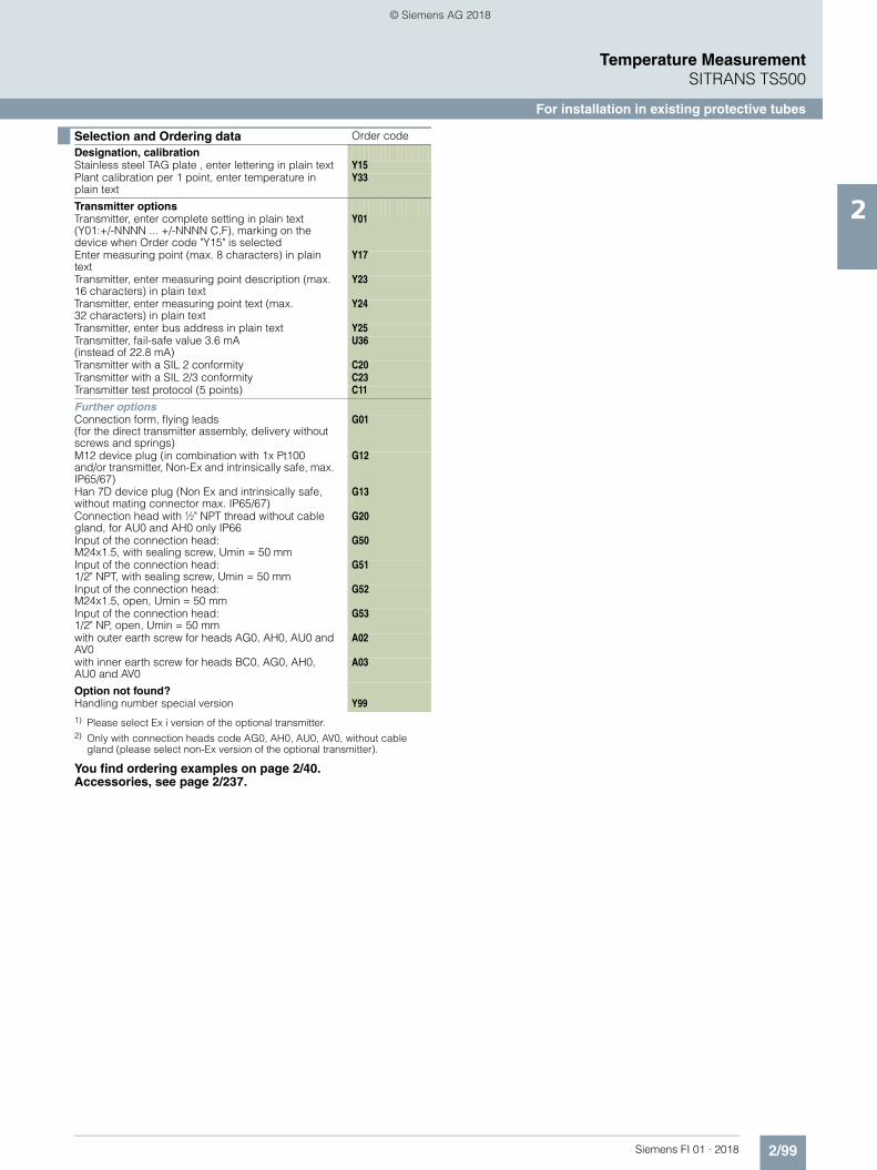
2/99Siemens FI 01 · 2018
Temperature MeasurementSITRANS TS500
For installation in existing protective tubes
2
1) Please select Ex i version of the optional transmitter.2) Only with connection heads code AG0, AH0, AU0, AV0, without cable
gland (please select non-Ex version of the optional transmitter).
You find ordering examples on page 2/40.Accessories, see page 2/237.
Designation, calibration Stainless steel TAG plate , enter lettering in plain text Y15 Plant calibration per 1 point, enter temperature in
plain textY33
Transmitter options Transmitter, enter complete setting in plain text
(Y01:+/-NNNN ... +/-NNNN C,F), marking on the device when Order code "Y15" is selected
Y01
Enter measuring point (max. 8 characters) in plain text
Y17
Transmitter, enter measuring point description (max. 16 characters) in plain text
Y23
Transmitter, enter measuring point text (max. 32 characters) in plain text
Y24
Transmitter, enter bus address in plain text Y25 Transmitter, fail-safe value 3.6 mA
(instead of 22.8 mA)U36
Transmitter with a SIL 2 conformity C20Transmitter with a SIL 2/3 conformity C23Transmitter test protocol (5 points) C11
Further options Connection form, flying leads
(for the direct transmitter assembly, delivery without screws and springs)
G01
M12 device plug (in combination with 1x Pt100 and/or transmitter, Non-Ex and intrinsically safe, max. IP65/67)
G12
Han 7D device plug (Non Ex and intrinsically safe, without mating connector max. IP65/67)
G13
Connection head with ½" NPT thread without cable gland, for AU0 and AH0 only IP66
G20
Input of the connection head:M24x1.5, with sealing screw, Umin = 50 mm
G50
Input of the connection head:1/2" NPT, with sealing screw, Umin = 50 mm
G51
Input of the connection head:M24x1.5, open, Umin = 50 mm
G52
Input of the connection head:1/2" NP, open, Umin = 50 mm
G53
with outer earth screw for heads AG0, AH0, AU0 and AV0
A02
with inner earth screw for heads BC0, AG0, AH0, AU0 and AV0
A03
Option not found? Handling number special version Y99
Selection and Ordering data Order code
© Siemens AG 2018

2/100 Siemens FI 01 · 2018
Temperature MeasurementSITRANS TSinsert
Measuring inserts for retrofits and upgrades European and American type
2
■ Dimensional drawings
SITRANS TSinsert measuring inserts for temperature sensors, replaceable, mineral-insulated design European type (DIN ceramic base), spring load approx. 6 mm (0.24 inch)/3 mm (0.12 inch) with transmitterAmerican type, spring load approx. 21 mm (0.83 inch); determination of measuring insert length, dimensions in mm (inch);Cold End types: see drawings on page 2/102
Ød Measuring insert outer diameterB Measuring insert length
NBL Non-bending lengthN Nominal length
TSL Temperature-sensitive lengthH1 Type Axx = 41 (1.61)
Type Bxx = 26 (1.02)
X Extension length
Recommended rebound:European versions with ceramic base = 3 (0.12)European versions with transmitter = 1 (0.04)American versions: 6.4 (0.25); round down to 6 (0.24)
F Floor strengthType 2: 3 (0.12)Type 3: 6 (0.24)Type 4: 4 (0.16)ASME types: 6.4 (0.25); round down to 6 (0.24)
L/U Thermowell lengthU for Form 2*/ 3*/ 4FL for Form 4
Example calculationsEuropean measuring insert (with ceramic base)Connection head BC0, Thermowell Form 2F, U = 225 mm, X = 64B = U + X + H1 + 3 – FB = 225 + 64 + 26 + 3 – 3 = 315American measuring insertConnection head AG0, Thermowell Form 4, L = 200 mmB = L + 6 - FB = 200 + 6 – 4 = 202For the NTP thread, please take tolerances into consideration and select a shorter sensor or use PTFE tape for mounting, for example: -3 (0.12).
Rebound
Seal about1 mm
Determination of the measuring insert length
K1 Screw depthK2 Screw depth
European type American type
B =
N +
H1
+ 3
- F
TSL NB
L
Ød
Ø42(1.66)
Ø33 (1.30)
25 (0
.99)
LX
17N
H1
B
F
K1
K2
150
(5.9
0)X
B =
U +
10
- F
TSL
NB
L
Ød
NPT½
NPT½
© Siemens AG 2018

2/101Siemens FI 01 · 2018
Temperature MeasurementSITRANS TSinsert
Measuring inserts for retrofits and upgrades European and American type
2
1) Pt1000 versions are also available. To find these, please switch to Online Configuration in the PIA Life Cycle Portal: www.siemens.com/pia-portal
Additional configurations on page after next page!
You find ordering examples on page 2/40!
Selection and Ordering data Article No.
SITRANS TSinsert for temperature sen-sors, replaceable, mineral-insulated design, European or American type
7MC701 7 - 77777
Click on the Article No. for the online configuration in the PIA Life Cycle Portal.
Measurement tip diameter6 mm (0.24 inch) 68 mm (0.31 inch) (with sleeve) 810 mm (0.39 inch) (with sleeve) 0
TypeEuropean type - DIN ceramic base 1European type - DIN flying leads, abso-lutely necessary with built-on transmitter
2
American type - ANSI (nipple spring) 5
Sensor1)
Please note: The accuracy class range can be lower than the measuring range. For more information, see page 2/17
Pt100, basis, -50 ... +400 °C(-58 ... +752 °F)
A
Pt100, vibration-resistant, -50 ... +400 °C (-58 ... +752 °F)
B
Pt100, expanded range, Umin = 100 mm-196 ... +600 °C (-321 ... +1 112 °F)
C
Thermocouple Type J, -40 ... +750 °C(-40 ... +1 382 °F)
J
Thermocouple Type K, -40 .. . +1 000 °C (-40 ... +1 832 °F)
K
Thermocouple Type N, -40 ... +1 000 °C (-40 ... +1 832 °F)
N
Sensor number/AccuracyCircuit Pt 100: 1 x 4-wire circuit or2 x 3-wire circuit, see "Measuring tech-nique: Connection types", page 2/19Single, basic accuracy(Class 2/Class B)
A
Single, increased accuracy (Class 1/Class A)
B
Single, highest accuracy(Class AA)
C
Double, basic accuracy(Class 2/Class B)
D
Double, increased accuracy (Class 1/Class A)
E
Double, highest accuracy (Class AA)
F
Measuring insert length B, standard145 mm (6.89 inch) 1 3205 mm (8.07 inch) 1 7275 mm (10.83 inch) 2 1315 mm (12.40 inch) 2 3345 mm (13.58 inch) 2 4375 mm (14.76 inch) 2 5405 mm (15.94 inch) 2 7435 mm (17.13 inch) 2 0555 mm (21.85 inch) 3 5585 mm (23.03 inch) 3 6
Measuring insert length B,customer-specificspecify length with Y44, s. page 2/9385 ... 100 mm (3.37 ... 3.94 inch) Initial: 100 mm (3.94 inch)
1 1
101 ... 150 mm (3.98 ... 5.91 inch)Initial: 145 mm (5.71 inch)
1 3
151 … 200 mm (5.95 ... 7.87 inch) Initial: 200 mm (7.87 inch)
1 5
201 … 250 mm (7.91 ... 9.84 inch) Initial: 205 mm (8.07 inch)
1 7
251 … 300 mm (9.88 ... 11.81 inch) Initial: 275 mm (10.83 inch)
2 1
301 … 350 mm (11.85 ... 13.78 inch) Initial: 315 mm (12.40 inch)
2 3
351 … 400 mm (13.82 ... 15.75 inch) Initial: 375 mm (14.76 inch)
2 5
401 … 450 mm (15.79 ... 17.72 inch) Initial: 405 mm (15.94 inch)
2 7
451 … 500 mm (17.76 ... 19.68 inch) Initial: 500 mm (19.68 inch)
3 1
501 … 550 mm (19.72 ... 21.65 inch) Initial: 525 mm (20.67 inch)
3 3
551 … 600 mm (21.69 ... 23.92 inch) Initial: 555 mm (21.85 inch)
3 5
601 … 700 mm (23.66 ... 27.56 inch) Initial: 655 mm (25.79 inch)
3 7
701 … 800 mm (27.60 ... 31.50 inch) Initial: 735 mm (28.94 inch)
4 1
801 … 900 mm (31.54 ... 35.43 inch) Initial: 825 mm (32.48 inch)
4 3
901 … 1 000 mm (35.47 ... 39.37 inch) Initial: 950 mm (37.40 inch)
4 5
1 001 … 1 500 mm (39.41 ... 59.05 inch) Initial: 1 250 mm (49.21 inch)
4 7
1 501 … 2 000 mm (59.09 ... 78.74 inch) Initial: 1 700 mm (66.93 inch)
4 8
Selection and Ordering data Article No.
SITRANS TSinsert for temperature sen-sors, replaceable, mineral-insulated design, European or American type
7MC701 7 - 77777
© Siemens AG 2018

2/102 Siemens FI 01 · 2018
Temperature MeasurementSITRANS TSinsert
Measuring inserts for retrofits and upgrades European and American type
2
Cold end type, ceramic base, dimensions in mm (inch)
Cold end type, free wire ends, dimensions in mm (inch)
European type:cold end type, built-on transmitter, dimensions in mm (inch)
Ø42(1.65)
Ø33(1.30)
25(0
.99)
33 (1.30)
28 (1
.10)
Ø42(1.65)
© Siemens AG 2018

2/103Siemens FI 01 · 2018
Temperature MeasurementSITRANS TSinsert
Measuring inserts for retrofits and upgrades European and American type
2
1) Please select Ex i version of the optional transmitter.2) Only with connection heads code AG0, AH0, AU0, AV0, without cable
gland (please select non-Ex version of the optional transmitter).
You find ordering examples on page 2/40.Accessories, see page 2/237.
Selection and Ordering data Order code
Further designs
Add "-Z" to Article No. and specify Order code.
Measuring insert length BSelect range, enter desired length in plain text (No entry = standard length)
Y44
OptionsAdd "-Z" to Article No. and add options, separate extensions with "+".
Built-in head transmitterMeasuring range to be set must be specified with plain text data "Y01".
SITRANS TH100, 4 ... 20 mA, Pt100 T10 SITRANS TH100 Ex i (ATEX), 4 ... 20 mA, Pt100 T11 SITRANS TH200, 4 ... 20 mA, Universal T20 SITRANS TH200 Ex i(ATEX), 4 ... 20 mA, Universal T21 SITRANS TH300, HART, Universal T30 SITRANS TH300 Ex i (ATEX), HART, Universal T31 SITRANS TH400 PA, Universal T40 SITRANS TH400 PA Ex i, Universal T41 SITRANS TH400 FF, Universal T45 SITRANS TH400 FF Ex i, Universal T46
Explosion protection Without explosion protection requirements
(Europe, Australia, New Zealand) E00
Intrinsic safety "i"/"IS1) according to ATEX and IECEx (Europe, Australia, New Zealand)
E01
For SITRANS TS500 in flameproof enclosure "d"/"XP type of protection; dust protection through housing "t"/"DIP"2) according to ATEX and IECEx(Europe, Australia, New Zealand)
E03
For SITRANS TS500 in non-sparking "nA"/"NI"according to ATEX and IECEx type of protection (Europe, Australia, New Zealand)
E04
Without explosion protection requirements(USA, Canada)
E17
Intrinsic safety "i"/"IS"1) according to cCSAus(USA, Canada)
E18
For SITRANS TS500 in flameproof enclosure "d"/"XP type of protection; dust protection through housing "t"/"DIP"2) according to cCSAus (USA, Canada);NPT connections at the enclosure are mandatory
E20
For SITRANS TS500 in flameproof enclosure "d"/"XP type of protection; dust protection through housing "t"/"DIP"2) according to cCSAus (USA);other connections (M, G, R)
E21
For SITRANS TS500 in non-sparking "nA"/"NI" type of protection according to cCSAus (USA, Canada)
E23
Without explosion protection requirements (China) E54 Intrinsic safety "i"/"IS"1) according to NEPSI (China) E55 For SITRANS TS500 in flameproof enclosure "d" type
of protection; dust protection through housing "t"2) according to NEPSI (China)
E56
For SITRANS TS500 in non-sparking "nA"/"NI" type of protection according to NEPSI (China)
E57
Without explosion protection requirements (EAC) E80 Intrinsic safety "i"/"IS"1) according to EACEx (EAC) E81 For SITRANS TS500 in flameproof enclosure "d"/"XP
type of protection; dust protection through housing "t"/"DIP"2) according to EACEx (EAC)
E82
For SITRANS TS500 in non-sparking "nA"/"NI" type of protection according to EACEx (EAC)
E83
Marine approvals
Det Norske Veritas Germanischer Lloyd (DNV GL) D01 Bureau Veritas (BV) D02 Lloyd’s Register of Shipping (LR) D04 American Bureau of Shipping (ABS) D05
Designation, calibration Stainless steel TAG plate , enter lettering in plain text Y15 Plant calibration per 1 point, enter temperature in
plain textY33
Transmitter options Transmitter, enter complete setting in plain text
(Y01:+/-NNNN ... +/-NNNN C,F)Y01
Enter measuring point (max. 8 characters) in plain text
Y17
Transmitter, enter measuring point description (max. 16 characters) in plain text
Y23
Transmitter, enter measuring point text (max. 32 characters) in plain text
Y24
Transmitter, enter bus address in plain text Y25 Transmitter, fail-safe value 3.6 mA
(instead of 22.8 mA)U36
Transmitter with a SIL 2 conformity C20Transmitter with a SIL 2/3 conformity C23Transmitter test protocol (5 points) C11
Selection and Ordering data Order code
© Siemens AG 2018

2/104 Siemens FI 01 · 2018
Temperature MeasurementSITRANS TSthermowells
Thermowells according to DIN 43772 - Form 4
2
■ Dimensional drawings
Thermowells according to DIN 43772 - Form 4
Since March 2000, DIN 43772 replaces the retracted DIN 43763: 1986-03
The name of the D sleeves is from the previous standard but still used today. The table below shows the order information for the corresponding successor products from DIN 43772.
7MT14, welded 7MT14, flange connection
Instrument connection
E1
Ø D2
C +2
min
. 4
L +2
Ø D3
Ø D
Instrumentconnection
Processconnection
E1
Ø D2
C +2
U +2
min
. 4
L +2
Ø D3
Ø D
Design L [mm] U [mm] Ordering data
D1 140 65 7MT1410-2*N00-0NQ2
D2 200 125 7MT1410-4*N00-0NQ4
D4 200 65 7MT1410-4*N00-0NQ2
D5 260 125 7MT1410-5*N00-0NQ4
Material:* = A: 1.4571* = B: 1.4404* = S: 1.7335* = T: 1.5415
© Siemens AG 2018

2/105Siemens FI 01 · 2018
Temperature MeasurementSITRANS TSthermowells
Thermowells according to DIN 43772 - Form 4
2
Selection and Ordering data Article No. Order code
Thermowells made of barstock according to DIN 43772 - Form 4 7 M T 7777 - 77777 - 7777 777
Click on the Article No. for the online configuration and configuration check in the PIA Life Cycle Portal.
Basic model Standard Process connection Form DIN Weld-in/flange connection Form 4/4F 1 4
External diameter of root D External diameter of tip D2 Bore hole D3
24 mm 12.5 mm 7 mm 1 26 mm 12.5 mm 7 mm 2 32 mm 17 mm 11 mm 3
Thermowell length L
110 mm 0 1 140 mm 0 2 170 mm 0 3
200 mm 0 4 260 mm 0 5 410 mm 0 6
Thermowell material
316Ti / 1.4571 A 316L / 1.4404 B Hastelloy C276 / 2.4819 E
1.7335 Heat-resistant S 1.5415 Heat-resistant T PTFE coating (thermowell made of 316/TI/L) U
ECTFE (HALAR) (thermowell made of 316/TI/L) V Stellite coating (thermowell made of 316/TI/L) W Customer-specific thermowell 9 8 8 N Y 9 9 + Y 4 6
Process connection material
Without (Form 4 for welding) N 316Ti / 1.4571 A 316L / 1.4404 B Hastelloy C276 / 2.4819 (flange with flanged wheel) E
1.7335 Heat-resistant S 1.5415 Heat-resistant T PTFE coating (thermowell made of 316/TI/L) U
ECTFE (HALAR) (thermowell made of 316/TI/L) V Stellite coating (thermowell made of 316/TI/L) W
Process connection
Without (Form 4 for welding) 0 0
Flange according DIN EN 1092-1 Sealing surface Initial: B1 for uncoated variants
• DN 40, PN 10 - 16 3 2 • DN 40, PN 25 - 40 3 3
• DN 50, PN 10 - 16 3 4 • DN 50, PN 25 - 40 3 5
Flansch according ASME B16.5 Sealing surface Initial: RF for uncoated variants
• 1.50 inch; Class 150 6 0 • 1.50 inch; Class 300 6 1 • 1.50 inch; Class 600 6 2
• 2.00 inch; Class 150 6 6 • 2.00 inch; Class 300 6 7 • 2.00 inch; Class 600 6 8
Customer-specific process connection Z 8 8 K 1 Y
Installation length U
For welding (no process connection) 0 N
130 mm 0 A 190 mm 0 B 340 mm 0 C
Customer-specific installation length 8 Y Y 4 4
© Siemens AG 2018

2/106 Siemens FI 01 · 2018
Temperature MeasurementSITRANS TSthermowells
Thermowells according to DIN 43772 - Form 4
2
Connection to thermometer E1 (female thread)
M18x1.5 Q M20x1.5 R M27x2.0 T
½-14 NPT U G½ W G¾ X
Special version Z Q 1 Y
Cone length C
Without (straight) 0
65 mm 2 73 mm 3 125 mm 4 133 mm 5 275 mm 6
Selection and Ordering data Article No. Order code
Thermowells made of barstock according to DIN 43772 - Form 4 7 M T 7777 - 77777 - 7777 777
Selection and Ordering data Order code
Options
Add "-Z" to Article No. and add options, separate extensions with "+".
Acceptance test certificate according to EN 10204-3.1
Material certificate for wetted parts C12
PMI (positive material ident.) for wetted parts C15
Pressure test C31
Helium leak test C32
Surface crack test C33
Visual, dimensional and functional check C34
Compliance with order C35
X-ray test concentricity of bore hole C47
X-ray test concentricity of bore hole C48
MR-01-75 NACE conformity C50
MR-01-03 NACE conformity C53
Grease-free (cleaned for oxygen applications, for example)
C51
Additional options
Thread protection stainless steel plug and chain A55
Forged flange A76
Sealing surface with concentric lines A77
TAG-marking Y15
Surface treatment, options on request
Wetted parts stained, neutralized and passivated W01
Wetted parts electropolished W02 Additional flange sealing surfaces
FF-Flat Face according to ASME B16.5 A70
RTJ-Ring-Type Joint according to ASME B16.5 A71
Type B2 according to EN1092-1 A72
Type C according to EN1092-1 A73
Type D according to EN1092-1 A74 Additional information
Add "-Z" to Article No. and specify Order code.
Additional information in plain text: Process connection (material, type)
K1Y
Additional information in plain text:Connection to thermometer E1
Q1Y
Customer specific production
Processing and quotation number of special version: specify in plain text
Y99
Selection and Ordering data Order code
© Siemens AG 2018

2/107Siemens FI 01 · 2018
Temperature MeasurementSITRANS TSthermowells
Thermowells according to ASME B40.9
2
■ Dimensional drawings
Thermowells according to ASME B 40.9
7MT21, for screwing in, straight, tapered pro-cess connection
7MT21, for screwing in, straight, cylindrical process connection
7MT31, for weld-in, straight
7MT22, for screwing in, reduced, tapered pro-cess connection
7MT22, for screwing in, reduced, cylindrical process connection
7MT32, for weld-in, reduced
7MT23, for screwing in, tapered, tapered pro-cess connection
7MT23, for screwing in, tapered, cylindrical process connection
7MT33, for weld-in, tapered
Tapered process connection
Head diameter
6.4
E1
Ø D3
Ø D
K
X1U
Cylindrical process connection
6.4
Head diameter
Ø D3
Ø D
X1U
E1
6.4
Head diam.
Ø D3
E1
Ø D
X1U
Tapered process connection
6.4
Head diameter
Ø D3
Ø D
Ø D2
K
X1U
L6
E1
Cylindrical process connection
6.4
Head diameter
Ø D3
Ø D2
Ø D
X1U
L6
E1
6.4
Head diam.
E1
Ø D2
X1U
Ø D
Ø D3
L6
Tapered process connection
6.4
Head diameter
Ø D3
Ø D2
Ø D
K
X1U
E1
Cylindrical process connection
6.4
Head diameter
Ø D3
Ø D2
Ø D
X1U
E1
6.4
Head diam.
Ø D3
Ø D
Ø D2
E1
X1U
© Siemens AG 2018

2/108 Siemens FI 01 · 2018
Temperature MeasurementSITRANS TS Thermowells
Thermowells according to ASME B40.9
2
7MT41, flange connection, straight 7MT51, Van Stone type, straight
7MT42, flange connection, reduced 7MT52, Van Stone type, reduced
7MT43, flange connection, tapered 7MT53 Van Stone type, tapered
6.4
Head diam.
Process connection
Ø D3
Ø D
X1U
E1
6.4
Process connection
Head diam.
Ø D3
E1
Ø D
X1U
6.4
Head diam.
Process connection
Ø D3
Ø D
Ø D2
X1
L6
U
E1
6.4
Head diam.
Process connection
E1
Ø D2
X1U
Ø D
Ø D3
L6
6.4
Head diam.
Process connection
Ø D3
Ø D
E1
Ø D2
X1U
6.4
Head diam.
Process connection
Ø D3
Ø D
Ø D2
E1
X1U
© Siemens AG 2018

2/109Siemens FI 01 · 2018
Temperature MeasurementSITRANS TS Thermowells
Thermowells according to ASME B40.9
2
Selection and Ordering data Article No. Order code
Thermowells made of barstock according to ASME 40.9 7 M T 7777 - 77777 - 7777 777
Click on the Article No. for the online configuration and configuration check in the PIA Life Cycle Portal.
Basic model Standard Process connection Form
ASME For screwing in Straight 2 1 ASME For welding Straight 3 1 ASME Flange connection Straight 4 1 ASME Van Stone type Straight 5 1
ASME For screwing in Reduced 2 2 ASME For welding Reduced 3 2 ASME Flange connection Reduced 4 2 ASME Van Stone type Reduced 5 2
ASME For screwing in Tapered 2 3 ASME For welding Tapered 3 3 ASME Flange connection Tapered 4 3 ASME Van Stone type Tapered 5 3
Connection to thermometer E1
M18x1.5 1 M20x1.5 2
½-14 NPT 5G½ 7
Special version 9 Y 9 9
Head diameter of the thermowell
For screwing in - width across flats For welding Flange connec-tion
Van Stone head/process connec-tion
26.7 mm 0 H27 33.4 mm 28.6 mm 33.4 mm / 51 mm 1 48.3 mm 30 mm 48.3 mm / 73 mm 2
H32 32 mm 60.3 mm / 92 mm 3 H36 34 mm 4 H42 38 mm 5
Head length X1
Screw-in
Weld-in Flange Van Stone
25 ... 50 mm: Initial 45 mm ✔ ✔ ✔ 0 51 ... 75 mm: Initial 64 mm ✔ ✔ ✔ ✔ 1 76 ... 101 mm: Initial 89 mm ✔ ✔ ✔ ✔ 2 102 ... 126 mm: Initial 114 mm ✔ ✔ ✔ ✔ 3
127 ... 151 mm: Initial 140 mm ✔ ✔ ✔ ✔ 4 152 ... 177 mm: Initial 165 mm ✔ ✔ ✔ ✔ 5 178 ... 202 mm: Initial 191 mm ✔ ✔ ✔ 6
Installation length U
25 ... 126 mm: Initial 25 mm A 127 ... 253 mm: Initial 127 mm B 254 ... 380 mm: Initial 254 mm C 381 ... 507 mm: Initial 381 mm D 508 ... 634 mm: Initial 508 mm E 635 ... 761 mm: Initial 635 mm F 762 ... 888 mm: Initial 762 mm G
© Siemens AG 2018

2/110 Siemens FI 01 · 2018
Temperature MeasurementSITRANS TS Thermowells
Thermowells according to ASME B40.9
2
Thermowell material
Screw-in
Weld-in Flange Van Stone
316L / 1.4404 ✔ ✔ ✔ ✔ B Carbon steel ✔ ✔ ✔ C Hastelloy C276 / 2.4819 (flange with flanged wheel) ✔ ✔ E
Hastelloy C22 / 2.4602 (flange with flanged wheel) ✔ ✔ F 304L / 1.4306 ✔ ✔ ✔ ✔ H 321 / 1.4541 ✔ ✔ ✔ K
Monel alloy 400 / 2.4360 (flange with flanged wheel) ✔ ✔ L Tantalum (sleeve, thermowell, made of 316/TI/L) ✔ Q Duplex / 1.4462 ✔ ✔ P
Super Duplex / 1.4410 ✔ ✔ RPTFE coating (thermowell made of 316/TI/L) ✔ ✔ UECTFE (HALAR) (thermowell made of 316/TI/L) ✔ ✔ V
Stellite coating (thermowell made of 316/TI/L) ✔ ✔ W Customer-specific thermowell (head diameter/X1/U/material) ✔ ✔ ✔ 9 8 N N G 1 Y
External diamater of root D/tip D2
Straight thermowell Reduced thermowell Tapered thermowell D D D2 D D2
0.50 in (12.7 mm) 0 0 0.625 in (15.9 mm) 0.625 in (15.9 mm) 0.5 in (12.7 mm) 0.625 in (15.9 mm) 0.5 in (12.7 mm) 0 1
0.75 in (19.1 mm) 0.75 in (19.1mm) 0.5 in (12.7 mm) 0.75 in (19.1mm) 0.5 in (12.7 mm) 0 2
1.00 in (25.4 mm) 1.00 in (25.4 mm) 0.5 in (12.7 mm) 0 31.25 in (31.8 mm) 1.25 in (31.8 mm) 0.5 in (12.7 mm) 1.00 in (25.4 mm) 0.50 in (12.7 mm) 0 41.50 in (38.1 mm) 1.50 in (38.1 mm) 0.5 in (12.7 mm) 1.00 in (25.4 mm) 0.75 in (19.1 mm) 0 5
1.25 in (31.8 mm) 0.50 in (12.7 mm) 0 71.25 in (31.8 mm) 0.75 in (19.1 mm) 0 8
D = 12 mm (0.47 in) 1.25 in (31.8 mm) 1.00 in (25.4 mm) 1 0
D = 14 mm (0.55 in) 1 1D = 16 mm (0.63 in) 1.50 in (38.1mm) 0.50 in (12.7 mm) 1 2D = 19 mm (0.75 in) 1.50 in (38.1 mm) 0.75 in (19.1 mm) 1 3
D = 22 mm (0.87 in) 1.50 in (38.1 mm) 1.00 in (25.4 mm) 1 4D = 25 mm (0.98 in) 1.50 in (38.1 mm) 1.25 in (31.8 mm) 1 5D = 27 mm (1.06 in) 1 6
12 mm (0.47 in) 9 mm (0.35 in) 3 114 mm (0.55 in) 9 mm (0.35 in) 3 316 mm (0.63 in) 9 mm (0.35 in) 3 616 mm (0.63 in) 13 mm (0.51 in) 3 7
16 mm (0.63 in) 14 mm (0.55 in) 3 819 mm (0.75 in) 9 mm (0.35 in) 4 119 mm (0.75 in) 13 mm (0.51 in) 4 2
19 mm (0.75 in) 14 mm (0.55 in) 4 322 mm (0.87 in) 9 mm (0.35 in) 4 622 mm (0.87 in) 13 mm (0.51 in) 4 7
22 mm (0.87 in) 14 mm (0.55 in) 4 822 mm (0.87 in) 16 mm (0.63 in) 5 025 mm (0.98 in) 9 mm (0.35 in) 5 3
25 mm (0.98 in) 13 mm (0.51 in) 5 425 mm (0.98 in) 14 mm (0.55 in) 5 525 mm (0.98 in) 16 mm (0.63 in) 5 6
25 mm (0.98 in) 19 mm (0.75 in) 5 727 mm (1.06 in) 9 mm (0.35 in) 6 127 mm (1.06 in) 13 mm (0.51 in) 6 2
27 mm (1.06 in) 14 mm (0.55 in) 6 327 mm (1.06 in) 16 mm (0.63 in) 6 427 mm (1.06 in) 19 mm (0.75 in) 6 5
27 mm (1.06 in) 22 mm (0.87 in) 6 632 mm (1.26 in) 9 mm (0.35 in) 7 032 mm (1.26 in) 13 mm (0.51 in) 7 1
Selection and Ordering data Article No. Order code
Thermowells made of barstock according to ASME 40.9 7 M T 7777 - 77777 - 7777 777
© Siemens AG 2018
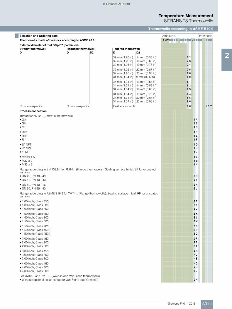
2/111Siemens FI 01 · 2018
Temperature MeasurementSITRANS TS Thermowells
Thermowells according to ASME B40.9
2
External diamater of root D/tip D2 (continued)
Straight thermowell Reduced thermowell Tapered thermowell D D D2 D D2
32 mm (1.26 in) 14 mm (0.55 in) 7 232 mm (1.26 in) 16 mm (0.63 in) 7 332 mm (1.26 in) 19 mm (0.75 in) 7 4
32 mm (1.26 in) 22 mm (0.87 in) 7 532 mm (1.26 in) 25 mm (0.98 in) 7 634 mm (1.34 in) 9 mm (0.35 in) 8 0
34 mm (1.34 in) 13 mm (0.51 in) 8 134 mm (1.34 in) 14 mm (0.55 in) 8 234 mm (1.34 in) 16 mm (0.63 in) 8 3
34 mm (1.34 in) 19 mm (0.75 in) 8 434 mm (1.34 in) 22 mm (0.87 in) 8 534 mm (1.34 in) 25 mm (0.98 in) 8 6
Customer-specific Customer-specific Customer-specific 9 0 L 1 Y
Process connection
Thread for 7MT2... (Screw-in thermowells) • G½" 1 A • G¾" 1 B • G1" 1 C
• R½" 1 D • R¾" 1 E • R1" 1 F
• ½" NPT 1 G • ¾" NPT 1 H • 1" NPT 1 J
• M20 x 1.5 1 L • M27 x 2 1 M • M33 x 2 1 N
Flange according to EN 1092-1 for 7MT4... (Flange thermowells), Sealing surface Initial: B1 for uncoated variants
• DN 25, PN 10 - 40 2 D • DN 40, PN 10 - 40 2 F
• DN 50, PN 10 - 16 2 H • DN 50, PN 25 - 40 2 J
Flange according to ASME B16.5 for 7MT4... (Flange thermowells), Sealing surface Initial: RF for uncoated variants
• 1.00 inch; Class 150 3 E • 1.00 inch; Class 300 3 F • 1.00 inch; Class 600 3 G
• 1.50 inch; Class 150 3 K • 1.50 inch; Class 300 3 L • 1.50 inch; Class 600 3 M
• 1.50 inch; Class 900 3 N • 1.50 inch; Class 1500 3 P • 1.50 inch; Class 2500 3 Q
• 2.00 inch; Class 150 3 R • 2.00 inch; Class 300 3 S • 2.00 inch; Class 600 3 T
• 3.00 inch; Class 150 4 C • 3.00 inch; Class 300 4 D • 3.00 inch; Class 600 4 E
• 4.00 inch; Class 150 4 G • 4.00 inch; Class 300 4 H • 4.00 inch; Class 600 4 J
For 7MT3... and 7MT5... (Weld-in and Van Stone thermowells) • Without (optional collar flange for Van-Stone see "Options") 0 N
Selection and Ordering data Article No. Order code
Thermowells made of barstock according to ASME 40.9 7 M T 7777 - 77777 - 7777 777
© Siemens AG 2018

2/112 Siemens FI 01 · 2018
Temperature MeasurementSITRANS TS Thermowells
Thermowells according to ASME B40.9
2
Process connection material (identical to thermowell) Screw-in
Weld-in Flange Van Stone
316L / 1.4404 ✔ ✔ ✔ B Carbon steel ✔ ✔ C Hastelloy C276 / 2.4819 (Flange with flanged wheel) ✔ E
Hastelloy C22 / 2.4602 ✔ F 304L / 1.4306 ✔ ✔ H 321 / 1.4541 ✔ K
Monel alloy 400 / 2.4360 (Flange with flanged wheel) ✔ L Tantal (sleeve, thermowell made of 316/TI/L) ✔ Q Duplex / 1.4462 ✔ P
Super Duplex ✔ RPTFE coating (thermowell made of 316/TI/L) ✔ UECTFE (HALAR) (thermowell made of 316/TI/L) ✔ V
Stellite coating (thermowell made of 316/TI/L) ✔ W Customer-specific ✔ ✔ ✔ 9 N N N 1 Y
Bore D3
D3 = 6.6 mm (0.260 in) 2 Customer-specific 9 R 1 Y
Selection and Ordering data Article No. Order code
Thermowells made of barstock according to ASME 40.9 7 M T 7777 - 77777 - 7777 777
Auswahl- und Bestelldaten Kurzangabe
Options
Add "-Z" to Article No. and add options, separate extensions with "+".
Acceptance test certificate according to EN 10204-3.1
Material certificate for wetted parts C12
PMI (positive material ident.) for wetted parts C15
Pressure test C31
Helium leak test C32
Surface crack test C33
Visual, dimensional and functional check C34
Compliance with order C35
X-ray test for welding seams C41
Ultrasound test for welding seams C44
X-ray test concentricity of bore hole C47
Ultrasound test concentricity of bore hole C48
MR-01-75 NACE conformity C50
MR-01-03 NACE conformity C53
Grease-free (cleaned for oxygen applications, for example)
C51
Additional options
Thread protection stainless steel plug and chain A55
Forged flange A76
Sealing surface with concentric lines A77
TAG-marking Y15 Full penetration options
Process connection welded G02 Surface treatment, options on request
Wetted parts stained, neutralized and passivated W01
Wetted parts electropolished W02
Additional flange sealing surfaces
FF-Flat Face according to ASME B16.5 A70
RTJ-Ring-Type Joint according to ASME B16.5 A71
Type B2 according to EN1092-1 A72
Type C according to EN1092-1 A73
Type D according to EN1092-1 A74 Additional information
Add "-Z" to Article No. and specify Order code.
Additional information in plain text:Thermowell (head diameter/X1/U/material)
G1Y
Additional information in plain text:AD root D / [tip D2]
L1Y
Additional information in plain text:Process connection (material/type):
N1Y
Additional information in plain text: Bore hole D3: R1Y Customer specific production
Length options U: Specify special installation length (in spec. area)
Y44
Length options X1: Specify special length extension (in spec. area)
Y45
Processing and quotation number of special version: specify in plain text
Y99
Optional collar flanges 316L (Van Stone only)
1.00 inch, Class 150 sealing surface initial: RF B24
1.00 inch, Class 300 sealing surface initial: RF B25
1.00 inch, Class 600 sealing surface initial: RF B26
1.50 inch, Class 150 sealing surface initial: RF B29
1.50 inch, Class 300 sealing surface initial: RF B30
1.50 inch, Class 600 sealing surface initial: RF B31
2.00 inch, Class 150 sealing surface initial: RF B35
2.00 inch, Class 300 sealing surface initial: RF B36
2.00 inch, Class 600 sealing surface initial: RF B37
Auswahl- und Bestelldaten Kurzangabe
© Siemens AG 2018

2/113Siemens FI 01 · 2018
Temperature MeasurementResistance thermometers
Temperature transmitters for mounting in the connection head
2
■ Overview
The following temperature transmitters are available for mount-ing in the connection head:
SITRANS TH100
Programmable two-wire temperature transmitter (4 to 20 mA), without electrical isolation, only for Pt100 resistance thermome-ters.
SITRANS TH200
Programmable two-wire temperature transmitter (4 to 20 mA), electrical isolation for resistance thermometers and thermocou-ple elements.
SITRANS TH300
Two-wire temperature transmitter with HART communication (4 to 20 mA), electrical isolation for resistance thermometers and thermocouple elements.
SITRANS TH400
Temperature transmitter with PROFIBUS PA or FOUNDATION Fieldbus connection, electrical isolation for resistance thermom-eters and thermocouple elements.
Note:• SITRANS TH100/TH200/TH300/TH400 can be fitted instead of
the terminal block or in the high hinged cover. Additional fitting only possible in high hinged cover.
• If using intrinsically-safe temperature sensors any installed temperature transmitters must also be intrinsically-safe.
■ Selection and Ordering Data
Detailed information on the transmitters can be found for the re-spective products under "Transmitters for temperature".
Transmitter to be fitted Order code
To order the sensor with a built-in temperature transmitter, add "-Z" to the Article No. of the sensor, and supplement by the following Order code:
SITRANS TH100, only for Pt100
• Without Ex T10
• EEx ia IIC and EEx n for zone 2 T11
• FM T13
SITRANS TH200
• Without Ex T20
• EEx ia IIC and EEx n for zone 2 T21
• FM (IS, I, NI) T23
SITRANS TH300
• Without Ex T30
• EEx ia IIC and EEx n for zone 2 T31
• FM (IS, I, NI) T33
SITRANS TH400 PA
• Without Ex T40
• EEx ia T41
SITRANS TH400 FF
• Without Ex T45
• EEx ia T46
• Customer-specific setting of the built-in transmitter (specify set-tings in plain text)
Y11
© Siemens AG 2018
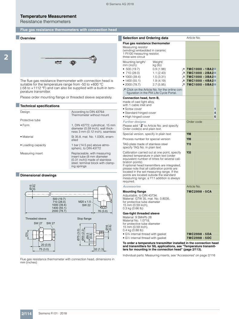
2/114 Siemens FI 01 · 2018
Temperature MeasurementResistance thermometers
Flue gas resistance thermometers with connection head
2
■ Overview
The flue gas resistance thermometer with connection head is suitable for the temperature range from -50 to +600 °C (-58 to +1112 °F) and can also be supplied with a built-in tem-perature transmitter.
Please order mounting flange or threaded sleeve separately.
■ Technical specifications
■ Dimensional drawings
Flue gas resistance thermometer with connection head, dimensions in mm (inches)
Design According to DIN 43764: Thermometer without mount
Protective tube
• Form 1, DIN 43772; cylindrical, 15 mm diameter (0.59 inch), wall thick-ness 3 mm (0.12 inch), seamless
• Material St 35.8, mat. No. 1.0305, enam-elled
• Loading capacity 1 bar (14.5 psi) above atmo-spheric, to DIN 43772
Measuring insert Replaceable, with measuring insert tube (8 mm diameter (0.31 inch)) made of stainless steel; terminal block with clamp-ing springs
M20 x 1.5SW 22
SW 27SW 27
Stop flangeThreaded sleeve
Ø9.
5 (0
.4)
76 (3.0)
500 (19.7)710 (28.0)
1000 (39.4)1400 (55.1)2000 (78.7)
Ø15
(0
.6)
75 (3.0)
Ø75
(3.0
)
20 (0.8)
G¾
32 (1.3)
Ø55
(2.2
) Ø16
(0
.6)
Selection and Ordering data Article No.
Flue gas resistance thermometerMeasuring resistor(winding) embedded in ceramic1 Pt100 measuring resistor,three-wire circuit
Mounting length/mm (inch):
Weight/kg (lb):
• 500 (19.7) 0.9 (1.98) 7MC1000 - 1BA27• 710 (28.0) 1.1 (2.43) 7MC1000 - 2BA27• 1000 (39.4) 1.5 (3.31) 7MC1000 - 3BA27• 1400 (55.1) 1.9 (4.19) 7MC1000 - 4BA27• 2000 (78.7) 2.7 (5.95) 7MC1000 - 5BA27
Click on the Article No. for the online con-figuration in the PIA Life Cycle Portal.
Connection head, form B,made of cast light alloy,with 1 cable inlet and • Screw cover 1• Standard hinged cover 4• High hinged cover 6
Further designs Order codePlease add "-Z" to Article No. and specify Order code(s) and plain text.
Special version, specify in plain text Y98
Process number for special version Y99
TAG plate made of stainless steelspecify TAG No. in plain text
Y15
Calibration carried out at one point, specify desired temperature in plain text (order equivalent number of times for several cali-bration points).If optional head transmitters are integrated, please note that all calibration points are located in the set measuring range. If the points are located outside the standard measuring range, a Y11 addition is always required.
Y33
Accessories Article No.
Mounting flange 7MC2998 - 5CAAdjustable, to DIN 43734;Material: GTW 35, mat. No. 0.8035,for protective tube diameter15 mm (0.59 inch),0.3 kg (0.66 lb)
Gas-tight threaded sleeveMaterial: 9 SMnPb 28 Material No. 1.0718,for protective tube diameter15 mm (0.59 inch),0.4 kg (0.88 lb)• G¾ internal thread with gasket 7MC2998 - 5DA• G½ internal thread with gasket 7MC2998 - 5DC
To order a temperature transmitter installed in the connection head and transmitters for SIL applications, see "Temperature transmit-ters for mounting in the connection head" (page 2/113).
Individual parts: Measuring inserts, see "Accessories".on page 2/116
© Siemens AG 2018

2/115Siemens FI 01 · 2018
Temperature MeasurementResistance thermometers
Resistance thermometers for damp rooms
2
■ Overview
The resistance thermometer for damp rooms is suitable for a temperature range from -30 to +60 °C (-22 to +140 °F).
■ Technical specifications
■ Dimensional drawings
Resistance thermometer for damp rooms, dimensions in mm (inches)
Protective tube Made of stainless steel
Connection head Made of cast light alloy, with cable bushing; made of plastic on request
Measuring insert 1 or 2 Pt measuring resistors to DIN EN 60751, connection in three-wire or two-wire system, class B
Degree of protection IP65 acc. to DIN EN 60529
Ø4.5 (0.2)
75 (3
.0)
13 (0.5) 52 (2.1)85 (3.4)
Ø6
(0.2
4)
80 (3.2)
63 (2
.5)
36
(1.4
)
60 (2
.4)
Pg 9
Selection and Ordering data Article No.
Resistance thermometer fordamp roomsstainless steel protective tube
• with one Pt100 measuring resistor0.1 kg (0.22 kg)
7MC1027-1AA
• with two Pt100 measuring resistors0.1 kg (0.22 kg)
7MC1027-1AB
Further designs Order codePlease add "-Z" to Article No. and specify Order code(s) and plain text.
Special version, specify in plain text Y98
Process number for special version Y99
TAG plate made of stainless steelspecify TAG No. in plain text
Y15
Calibration carried out at one point, specify desired temperature in plain text (order equivalent number of times for several cali-bration points).If optional head transmitters are integrated, please note that all calibration points are located in the set measuring range. If the points are located outside the standard measuring range, a Y11 addition is always required.
Y33
To order a temperature transmitter installed in the connection head and transmitters for SIL applications, see "Temperature transmit-ters for mounting in the connection head" (page 2/113).Note:Additional fitting of head mounted transmitter of SITRANS TH series is possible.
© Siemens AG 2018

2/116 Siemens FI 01 · 2018
Temperature MeasurementResistance thermometers
Accessories – Welding-type protective tubes, neck tubes and connection heads
2
■ Welding-type protective tube
Welded-in protective tubes to DIN 43772 for SITRANS TS500• Tapered shank with cylindrical welding stubs• For measuring insert tube with 6 mm (0.24 inch)• OD female thread M18 x 1.5
■ Neck tube
Extension tube for SITRANS TS500• Made of stainless steel, mat. No. 1.4571• With threads at both ends• For measuring insert tube with 6 mm (0.24 inch) OD
■ Dimensional drawings
Connection head type B for SITRANS TS500
Connection head, Type B, degree of protection IP54, made of aluminium, with screw cover, dimensions in mm (inches)
Connection head, Type B, degree of protection IP54, made of plastic,with screw cover, dimensions in mm (inches)
Connection head, Type B, degree of protection IP65, made of aluminium, with standard hinged cover, dimensions in mm (inches)
Connection head, Type B, degree of protection IP65, made of aluminium, with high hinged cover, dimensions in mm (inches)
Connection head, Type B-VA, degree of protection IP65, made of stainless steel, with screw cover, dimensions in mm (inches)
M20 x 1.5
M24 x 1.5
17
(0.6
7)
26
(1.0
2)
≈ 50 (1.97)
≈ 73
(2.8
7)≈
50 (1
.97)
M20 x 1.5
M24 x 1.5
26 (1
.02)
72 (2
.83)
≈ 100 (3.94) 17
(0.6
7)
M20 x 1.5
M24 x 1.517
(0.6
7)
26
(1.0
2)
≈ 41
(1.6
1)≈
85 (3
.35)
≈ 65 (2.56)
≈ 41
.5
(1.6
3)
M20 x 1.5
M24 x 1.5
≈ 11
4 (4
.49
)
17
(0.6
7)
26
(1.0
2)
≈ 65 (2.56)
M20 x 1.5
M24 x 1.5
Knurled
Gasket
15
(0.5
9)
53 (2
.09)
Ø29 (1.14)
Ø59 (2.32)
83 (3
.27)
17
(0.6
7)26
(1
.02)
© Siemens AG 2018

2/117Siemens FI 01 · 2018
Temperature MeasurementResistance thermometers
Accessories – Welding-type protective tubes, neck tubes and connection heads
2
Selection and Ordering data Article No.
Welded-in protective tubes to DIN 43772 for SITRANS TS500Welding form 4• Tapered shank with cylindrical welding stub• For measuring insert tube with 6 mm (0.24 inch) OD• OD female thread M18 x 1.5
Up to 540 °C (1004 °F)Protective tube to DIN 43772, form 4 made of 13 CrMo 44, mat. No. 1.7335
Cone length Cmm (inch)
Protective tube length Lmm (inch)
Weightmm (inch)
• 65 (2.56) 140 (5.51) 0.3 (0.66) 7MC1905-1GA• 65 (2.56) 200 (7.87) 0.5 (1.1) 7MC1905-2GA• 125 (4.92) 200 (7.87) 0.5 (1.1) 7MC1905-3GA• 125 (4.92) 260 (10.24) 0.6 (1.32) 7MC1905-4GA
Up to 550 °C (1022 °F)Protective tube to DIN 43772, form 4 made of 6 CrNiMoTi 17122, mat. No. 1.4571
Cone length Cmm (inch)
Protective tube length Lmm (inch)
Weightkg (lb)
• 65 (2.56) 140 (5.51) 0.3 (0.66) 7MC1905-1DA• 65 (2.56) 200 (7.87) 0.5 (1.1) 7MC1905-2DA• 125 (4.92) 200 (7.87) 0.5 (1.1) 7MC1905-3DA• 125 (4.92) 260 (10.24) 0.6 (1.32) 7MC1905-4DA
Selection and Ordering data Article No.
Extension tube for SITRANS TS500Neck tube for high-pressure screw-in resistance thermometermade of stainless steel, mat. No. 1.4571, with thread at both ends, for measuring insert tube with 6 mm (0.24 inch) OD
Neck tube length
Total length of the resistance thermometer,without connection head
Protective tube length
Weight
mm (inch) mm (inch) mm (inch) kg (lb)
• 135 (5.31) 395 (15.55) 260 (10.24) 0.14 (0.31) 7MC1906-1AA• 165 (6.50) 305/365 (12.01/14.37) 140/200 (5.51/7.87) 0.15 (0.33) 7MC1906-2AA• 195 (7.68) 395 (15.55) 200 (7.87) 0.18 (0.40) 7MC1906-3AA• 225 (8.86) 365 (14.37) 140 (5.51) 0.20 (0.44) 7MC1906-4AA• 255 (10.04) 395 (15.55) 140 (5.51) 0.22 (0.49) 7MC1906-5AA
Selection and Ordering data Article No
Connection head type B for SITRANS TS500
Degree of protection IP54• Connection head type: similar to BA0; aluminium;
Flange cover7MC1907-1BA
• Connection head type: Similar to BM0; plastic; screw cover
7MC1907-1BK
Degree of protection IP65• Connection head type: Similar to BB0; aluminium;
small hinged lid7MC1907-1BF
• Connection head type: Similar to BC0; aluminium; high hinged lid
7MC1907-1BL
• Connection head type: B-VA, stainless steel 7MC1907-1BV• Quick-release clamp for
connection heads BB0, BC0,degree of protection of connection head reduced to IP20, weight: 0.02 kg (0.04 lb)
7MC1907-1BS
© Siemens AG 2018

2/118 Siemens FI 01 · 2018
Temperature MeasurementThermocouples
Technical description
2
■ Design
A thermocouple comprises•The thermocouple element (sensor) and•The mounting and connection parts required in each case.
The thermocouple element is formed by two conductors of dis-similar metals or metal alloys which are soldered or welded to-gether at one end, the measuring junction:
Thermocouple element
■ Function
Measuring principle of the thermocouple element
If the measuring junction is exposed to a temperature different from that at the free ends of the thermocouple, a voltage (the thermoelectric voltage, Seebeck effect) is produced at these free ends. The magnitude of the thermoelectric voltage depends on the difference in temperature between the measuring junction and the free ends, and on the combination of materials in the thermocouple. Since a thermocouple always measures a tem-perature difference, the free ends of the thermocouple must be connected to a reference junction (cold junction) and held con-stant at a known temperature.
Calibration data for thermoelectric voltages and permissible deviations
The calibration data and the permissible deviations for com-monly used thermocouples are defined isee Technical Data, Table "Calibration data for thermoelectric voltages and errorlimits").
The thermocouples Cu-CuNi and Fe-CuNi to DIN 43710 are used for replacement purposes. Thermocouples of class 2 are supplied as standard. For more accurate measurements, ther-mocouples are available with half the DIN tolerance or with a test certificate. The tolerances only apply to the condition upon de-livery.
During operation at high temperatures, the tolerances of the thermocouples may change due to absorption of foreign matter, oxidation or evaporation of alloy components.
Mode of operation
The thermocouples are extended from the connection point to a point whose temperature is as constant as possible (the cold junction) by means of extension leads.
The extension leads have the same color code as the associated thermocouple elements; the positive pole is marked in red. Correct polarity must be ensured since otherwise large errors will occur. Up to 200 °C, the same calibration data and toler-ances apply to the extension leads as to the corresponding thermo-couples.
The influence of temperature changes at the cold junction can be balanced by means of a compensating circuit, e.g. a com-pensating box. The reference temperature is 0 (32 °F) or20 °C (68 °F).
It is also possible to keep the cold junctions at a constant tem-perature of 50, 60 or 70 °C (122, 140 or 158 °F) using a thermo-stat (for several measuring junctions).
The connections from the cold junction to the measuring or pro-cess instrument are made using copper leads. With energy-con-suming instruments such as indicators or multipoint recorders, the complete measuring circuit (thermocouple, extension lead and copper lead) must be balanced in the operating condition using a resistor. SITRANS T transmitters and process recorders for connection to thermocouple elements have a built-in com-pensating circuit for balancing the effect of the ambient tem-perature on the cold junction. Lead balancing is not necessary in this case because of the high input impedance.
Protection fitting/protective tubes
The thermocouple can be protected against mechanical stress and chemical attack by a ceramic or metal protective tube which may be mounted using flanges, screwed glands or by welding into the pipeline or tank. The thermocouple element terminates in the connection head.
Installation examples with specification of the recommended thermocouples and protective tube materials are listed on pages "Technical Data"and "Installation Examples".
Owing to the different operating conditions, no guarantee can be given for protective fittings. The manufacturer is responsible for damages and measuring errors caused by wrong installation in compliance with the General Terms of Delivery if the instruments have been installed by the manufacturer and if the specifications for the operating conditions furnished by the customer were cor-rect and sufficiently detailed.
Thermocouple elements are very compatible since it is almost always possible to adapt them in shape and size to the particular problem. The temperature-responsive part is almost point-shaped. Thermocouple elements are therefore particularly suit-able for measuring rapidly changing temperatures.
8
9
1
2
7
3
45 6
10
11
12
13
1415
1 Ceramic protective tube2 Locating flange3 Support tube4 Retaining ring5 Terminal6 Connection head7 Terminal block8 Temperature sensor
9 Balancing resistor10 Lead11 Cold junction12 Extension lead13 Connection point14 Thermocouple element with
positive and negative legs
15 Measuring junction
Cross section of thermocouple
Connection diagram
Thermocouple element with insulating beads
Nominal lengthlN
°C
+ -
l N
© Siemens AG 2018

2/119Siemens FI 01 · 2018
Temperature MeasurementThermocouples
Straight thermocouples to DIN 43733, with connection head
2
■ Overview
The straight thermocouple together with a metal protective tube is suitable for temperatures from 0 to 1250 °C (32 to 2282 °F) and can be supplied with a built-in temperature transmitter.
■ Technical specifications
■ Dimensional drawings
Straight thermocouple, dimensions in mm (inches)
■ Design
Straight thermocouple with base-metal element Ni Cr/Ni with metal pro-tective tube
Thermocouples Ni Cr/Ni type K
• Number 1 or 2
• Leg diameter 2 ... 3 mm (0.08 ... 0.12 inch)
• Insulation of legs Insulating beads
Protective tube Metal
Connection head Form A, DIN 43729; made of cast light alloy, with one cable bushing
M20 x 1.5SW 22
97 (3.8)
500 (19.7)710 (28.0)
1000 (39.4)
Ø22
(0.9
)Ø
26 (1
.0)
100
(3.9
)
Metal protective tube
Thermocouple element with insulating beads
Connection head
Terminal block
Section A - A
A
A
Selection and Ordering data Article No.
Straight thermocouple withNi Cr/Ni thermocouple (type K)
7 M C 2 0 0 0 - 777 0 7
with metallic protective tube
Click on the Article No. for the online con-figuration in the PIA Life Cycle Portal.
Nominal lengthEnter customer specific length with Y44, see Order codes below
300 ... 500 mm (11.81 ... 19.68 inch)Initial: 500 mm (19.68 inch)
1
501 ... 710 mm (19.72 ... 27.95 inch)Initial: 710 mm (27.95 inch)
2
711 ... 1 000 mm (27.11 ... 39.37 inch)Initial: 1 000 mm (39.37 inch)
3
Protective tube
to 1 000 °C (1 832 °F) X 10 CrAl 24, material No. 1.4762
D
Ø 22 mm x 2 mm (0.87 inch x 0.079 inch)Leg diameter 2 mm (0.08 inch)
to 1 100 °C (2 012 °F)X 18 CrN28, material No. 1.4749
E
Ø 26 mm x 4 mm (1.02 inch x 0.16 inch)Leg diameter 3 mm (0.12 inch)
to 1 200 °C (2 192 °F)X 15 CrNi Si 24 19, material No. 1.4841
F
Ø 22 mm x 2 mm (0.87 inch x 0.079 inch)Leg diameter 2 mm (0.08 inch)
to 1 250 °C (2 282 °F)CrAl 205 (Kantal AF), material No. 1.4767
H
Ø 22 mm x 2 mm (0.87 inch x 0.079 inch)Leg diameter 3 mm (0.12 inch)
Number of thermocouples
1 thermocouple C
2 thermocouples D
Connection head, form A,
made of cast light alloy, with 1 cable inlet and - screw cover 1- high hinged cover 6
Selection and Ordering data Order code
Straight thermocouple withNi Cr/Ni thermocouple (type K)for temperatures to 1250 °C (2282 °F);with metallic protective tube
Further designsPlease add "-Z" to Article No. and specify Order code(s) and plain text.
Special version, specify in plain text Y98
Process number for special version Y99
TAG plate made of stainless steelspecify TAG No. in plain text
Y15
Calibration carried out at one point, specify desired temperature in plain text (order equivalent number of times for several cali-bration points).
Y33
Insertion length customer-specificSelect range, enter desired length in plain text (No entry = standard length)
Y44
To order a temperature transmitter installed in the connection head, see "Temperature transmitters for installation in the connection head" (page 2/113).
Installation of a transmitter is only possible here in the versions with a high hinged cover (7MC2000-....6).
© Siemens AG 2018

2/120 Siemens FI 01 · 2018
Temperature MeasurementThermocouples
Straight thermocouples Individual parts and accessories
2
Selection and Ordering data Article No.
Metallic protective tubes for straight thermocouple elements according to DIN 43733
X 10 CrAl 24, material No. 1.4762; 22 mm x 2 mm (; 0.87 inch x 0.08 inch), 0.55 ... 1.10 kg (1.21 ... 2.42 lb), dishedNominal lengthin mm (inch):
Protective tube lengthin mm (inch):
• 500 (19.7) 520 (20.5) 7 M C 2 9 0 0 - 1 D A• 710 (28.0) 730 (28.7) 7 M C 2 9 0 0 - 2 D A• 1000 (39.4) 1020 (40.2) 7 M C 2 9 0 0 - 3 D A
X 10 CrAl 24, material No. 1.4749; 26 mm x 4 mm (; 1.02 inch x 0.16 inch), 1.25 ... 2.20 kg (2.76 ... 4.85 lb), dishedNominal lengthin mm (inch):
Protective tube lengthin mm (inch):
• 500 (19.7) 520 (20.5) 7 M C 2 9 0 0 - 1 E C• 710 (28.0) 730 (28.7) 7 M C 2 9 0 0 - 2 E C• 1000 (39.4) 1020 (40.2) 7 M C 2 9 0 0 - 3 E C
X 15 CrNiSi 25 20, material No. 1.4841; 22 mm x 2 mm (; 0.87 inch x 0.08 inch), 1.05 kg (2.31 lb), dishedNominal lengthin mm (inch):
Protective tube lengthin mm (inch):
• 1000 (39.4) 1020 (40.2) 7 M C 2 9 0 0 - 3 FA
CrAl 205 (Megapyr), material No. 1.4767; 22 mm x 2 mm (; 0.87 inch x 0.05 inch), 0.55 ... 1.10 kg (1.21 ... 2.42 lb)Nominal lengthin mm (inch):
Protective tube lengthin mm (inch):
• 500 (19.7) 520 (20.5) 7 M C 2 9 0 0 - 1 H A• 710 (28.0) 730 (28.7) 7 M C 2 9 0 0 - 2 H A• 1000 (39.4) 1020 (40.2) 7 M C 2 9 0 0 - 3 H A
Selection and Ordering data Article No.
Thermocouples elements for straight thermocouple according to DIN 43733
Base-metal thermocouple with insulating beadsWire diameter 3 mm (0.12 inch)Ni Cr/Ni, to 1000 °C (maximal 1300 °C),(to 1832 °F (max. 2372 °F))0.55 ... 2.10 kg (1.21 ... 4.63 lb)Nominal length L1 inmm (inch):
Thermocouple length L2 in mm (inch):
• 500 (19.7) 540 (21.3) 7 M C 2 9 0 3 - 1 C A• 710 (28.0) 750 (29.5) 7 M C 2 9 0 3 - 2 C A• 1000 (39.4) 1040 (40.9) 7 M C 2 9 0 3 - 3 C A
© Siemens AG 2018

2/121Siemens FI 01 · 2018
Temperature MeasurementThermocouples
Straight thermocouples Individual parts and accessories
2
■ Connection heads
Connection head, Type A (without terminal block and terminals) for protective tube diameter (bore = protective tube diameter +0.5 mm (0.02 inch))
■ Installation accessories for connection heads
• Terminal block• Terminal• Set of gaskets• Set of washers• Mounting flange• Threaded sleeve
■ Dimensional drawings
Mounting flange to DIN 43734 (left) and threaded sleeve (right) for install-ing straight thermocouples, dimensions in mm (inches)
Selection and Ordering data Article No.
Connection head, Type A,(without terminal block and terminals)1 Cable inlet, degree of protection IP53, 0.35 kg (0.77 lb)
Cast light alloyfastener, unscrewablefor protective tube diameter in mm (inch)(bore = protective tube diam. +0.5 mm) (0.02 inch):• 22 (0.87) 7 M C 2 9 0 5 - 1 A A• 26 (1.02) 7 M C 2 9 0 5 - 1 B A
Cast light alloyhigh hinged coverfor protective tube diameter in mm (inch)(bore = protective tube diam. +0.5 mm) (0.02 inch):• 22 (0.87) 7 M C 2 9 0 5 - 4 A A• 26 (1.02) 7 M C 2 9 0 5 - 4 B A
Selection and Ordering data Article No.
Mounting accessories
Terminal block without terminals 7 M C 2 9 9 8 - 1 A Afor base-metal thermocouples; 0.06 kg (0.13 lb)
Terminal 7 M C 2 9 9 8 - 1 B Afor base-metal thermocouples; 0.01 kg (0.02 lb)
Set of gaskets (100 off) 7 M C 2 9 9 8 - 1 C Afor the connection head cover;0.01 kg (0.02 lb)
Set of washers (100 off) 7 M C 2 9 9 8 - 1 C B
for the terminal block; 0.01 kg (0.02 lb)
Mounting flange, adjustable; made of GTW• for protective tube outer diameters
22 mm (0.87 inch); 0.35 kg (0.77 lb)7 M C 2 9 9 8 - 2 C B
• for protective tube outer diameters26 mm (1.02 inch); 0.32 kg (0.71 lb)
7 M C 2 9 9 8 - 2 C C
Threaded sleeveGas-tight up to 1 bar (14.5 psi), adjustable, materiall No. 1.0718, with gasket; 0.40 kg (0.88 lb)• for protective tube outer diameters
22 mm (0.87 inch), G17 M C 2 9 9 8 - 2 D B
• for protective tube outer diameters26 mm (1.02 inch), G1
7 M C 2 9 9 8 - 2 D C
For protective tube diameter 22 mm (0.9 inch)1)
SW 41Ø9.5 (0.4)
SW 36
65 (2
.6)
33 (1.3)1)
32 (1
.3)
23 (0.9)1)
8 (0
.31)
M6 DIN 84
70 (2.8)90 (3.5)
≈90 (3.5)20 (0.8)
G1
© Siemens AG 2018

2/122 Siemens FI 01 · 2018
Temperature MeasurementTransmitters in a compact design
SITRANS TH100 Slim (Pt100)
2
■ Overview
SITRANS TH100 Slim is particularly suited for the production of compact thermometers with integrated transmitter.
Its cylindrical stainless steel enclosure is simply welded to the basic body of the compact thermometer.
Its compact design makes the SITRANS TH100 Slim the ideal solution for manufacturers from a wide variety of industries.
For the parameterization, the SIPROM T software is used in com-bination with the modem for SITRANS TH100/TH200.
■ Benefits
• Transmitter in two-wire technology with M12 device plug for installation on compact thermometer.
• Solution for easy and space-saving temperature measure-ments in a variety of industries.
• Programmable; as a result, the sensor connection, measuring range and much more is programmable.
■ Application
The SITRANS TH100 Slim transmitter can be used in combina-tion with Pt100 compact resistance thermometers for tempera-ture measurement in all industries. Thanks to its compact de-sign, it can be attached to all kinds of designs.
The output signal is a load-independent direct current of 4 to 20 mA which is proportional to the temperature.
Parameterization is implemented over the PC using the parame-terization software SIPROM T and the modem for SITRANS TH100/TH200. If you already have a "Modem for SITRANS TK" (article number 7NG3190-6KB), you can continue to use this for parameterization of the SITRANS TH100.
■ Function
Mode of operation
The measured signal supplied by a Pt100 resistance thermome-ter (2, 3 or 4-wire system) is amplified in the input stage. The volt-age, which is proportional to the input variable, is then converted into digital signals by a multiplexer in an analog-to-digital con-verter. They are converted in the microcontroller in accordance with the sensor characteristics and further parameters (measur-ing range, damping, ambient temperature, etc.).
The signal prepared in this way is converted in an analog-to-dig-ital converter into a load-independent direct current of 4 to 20 mA.
An EMC filter protects the input and output circuits against elec-tromagnetic interferences.
SITRANS TH100 Slim, function block diagram
InputPt100 Resistance thermometerEMC_1 Input level with protective componentsIC Constant current sourceMUX MultiplexerA/D Analog-digital converter
OutputD/A Digital-analog converterU/I Voltage transformers, current transformers, constant voltage and reference voltage sourceEMC_2 Output level with protective componentsUaux Auxiliary power supplyIout Output current
MicrocontrollerμC Linearization functions and storage of all data
A/D
D/A
Uaux, Iout
6
5
3
4 EMC_1Pt100MUX
μC
UI
Uref
EMC_2 4 ... 20 mA
UrefIc
+
-
© Siemens AG 2018

2/123Siemens FI 01 · 2018
Temperature MeasurementTransmitters in a compact design
SITRANS TH100 Slim (Pt100)
2
■ Technical specifications
■ Selection and Ordering data Article No.
SITRANS TH100 Slim
Input
Resistance thermometer
Measured variable Temperature
Sensor type PT100 to IEC 60751
Characteristic curve Temperature-linear
Type of connection 2-, 3- or 4-wire circuit
Resolution 14 bit
Measuring accuracy < 0.25 °C (0.45 °F)
Repeatability < 0.1 °C (0.18 °F)
Measuring current Approx. 0.4 mA
Measuring cycle < 0.7 s
Measuring range -60 ... +160 °C (-76 ... +320 °F)
Measuring span 25 ... 220 °C (45 ... 396 °F)
Unit °C or °F
Offset Programmable:-100 ... +100 °C (-180 ... +180 °F)
Line resistance Max. 20 (total from feeder and return conductor)
Noise rejection 50 and 60 Hz
Output
Output signal 4 ... 20 mA, two-wire
Auxiliary power 8.5 ... 36 V DC (30 V for Ex)
Max. load (Uaux – 8.5 V)/0.023 A
Overrange 3.6 ... 23 mA, infinitely adjustable (factory setting: 3.84 ... 20.5 mA)
Error signal (in the event of sensor breakage)
3.6 ... 23 mA, infinitely adjustable (factory setting: 3.6 mA or 22.8 mA)
Damping time 0 ... 30 s
Protection Against reverse polarity
Resolution 12 bit
Accuracy at 23 °C (73.4 °F) < 0.1 % of span
Temperature effect < 0.13 %/10 °C (0.13 %/18 °F)
Effect of auxiliary power < 0.02 % of span/V
Effect of load impedance < 0.055 % of max. span/100
Long-term drift • < 0.025 % of max. span in the first month
• < 0.035 % of max. span after one year
• < 0.05 % of max. span after 5 years
Ambient conditions
Ambient temperature range -40 ... +85 °C (-40 ... +185 °F)
Storage temperature range -40 ... +85 °C (-40 ... +185 °F)
Relative humidity 98 %, with condensation
Electromagnetic compatibility According to EN 61326 and NAMUR NE21
Design
Weight 42 g
Dimensions See dimensional drawing
Material 316L stainless steel
Degree of protection according to IEC 60529• Enclosure IP67
Software requirements for SIPROM T
PC operating system Windows ME, 2000 and XP; also Win-dows 95, 98 and 98SE, but only in connection with RS232 modem
Factory setting:• Pt100 (IEC 751) with 3-wire system• Measuring range: 0 ... 100 °C (32 ... 212 °F)• Error signal in the event of sensor breakage: 22.8 mA• Sensor offset: 0 °C (0 °F)• Damping 0.0 s
SITRANS TH100 Slimtemperature transmitters for Pt100
For welding to compact thermometersTwo-wire system, 4 ... 20 mA, programmable, without electrical isolation• Without explosion protection 7NG3150-0NN00
Accessories
Modem for SITRANS TH100 and TH200 incl. SIPROM T parameterization software
} 7NG3092-8KU
With USB connection
© Siemens AG 2018

2/124 Siemens FI 01 · 2018
Temperature MeasurementTransmitters in a compact design
SITRANS TH100 Slim (Pt100)
2
■ Dimensional drawings
SITRANS TH100 Slim, dimensions in mm (inch)
■ Schematics
SITRANS TH100 Slim, auxiliary power and sensor connection
SITRANS TH100 Slim, sensor connection assignment
M12 device plug
Transmitter housing
Ø16,3+0.0 -0.1
Ø18 (0.71)M12x1
68(2.68)
56(2.20)
2 (0.78)
3 (0.12)
(Ø0.64 +0.0 -0.004)
Power supply U
N. C.
N. C.
Sensorconnections
3 6
54
63
54 U+
U-
Pt100
Pt100Pt100
3
4
6
5
3
4
6
5
3
4
6
5
© Siemens AG 2018

2/125Siemens FI 01 · 2018
Temperature MeasurementTransmitters for mounting in sensor head
SITRANS TH100 (Pt100)
2
■ Overview
The SITRANS TH100 dispenses with electrical isolation and uni-versal sensor connection to provide a low-cost alternative for Pt100 measurements.
For the parameterization, the SIPROM T software is used in com-bination with the modem for SITRANS TH100/TH200.
Its extremely compact design makes the SITRANS TH100 ideal for the retrofitting of measuring points or for the use of analog transmitters.
The transmitter is available as a non-Ex version as well as for use in potentially explosive atmospheres.
■ Benefits
• Two-wire transmitter• Assembly in connection head type B (DIN 43729) or larger, or
on a standard DIN rail• Can be programmed, which means that the sensor connec-
tion, measuring range, etc. can also be programmed• Intrinsically-safe version for use in potentially explosive areas
■ Application
Used in conjunction with Pt100 resistance thermometers, the SITRANS TH100 transmitters are ideal for measuring tempera-tures in all industries. Due to its compact size it can be installed in the connection head type B (DIN 43729) or larger.
The output signal is a direct current from 4 to 20 mA that is pro-portional to the temperature.
Parameterization is implemented over the PC using the parame-terization software SIPROM T and the modem for SITRANS TH100/TH200. If you already have a "modem for SITRANS TK" (Article No. 7NG3190-6KB), you can continue us-ing this to parameterize the SITRANS TH100.
Transmitters of the "intrinsically-safe" type of protection can be installed within potentially explosive atmospheres. The devices comply with the Directive 2014/34/EU (ATEX), as well as FM and CSA regulations.
■ Function
Mode of operation
The measured signal supplied by a Pt100 resistance thermome-ter (2, 3 or 4-wire system) is amplified in the input stage. The volt-age, which is proportional to the input variable, is then converted into digital signals by a multiplexer in an analog/digital converter. They are converted in the microcontroller in accordance with the sensor characteristics and further parameters (measuring range, damping, ambient temperature etc.).
The signal prepared in this way is converted in a digital/analog converter into a load-independent direct current of 4 to 20 mA.
An EMC filter protects the input and output circuits against elec-tromagnetic interferences.
SITRANS TH100, function diagram
InputPt100 Resistance thermometerEMC_1 Input level with protective componentsIC Constant current sourceMUX MultiplexerA/D Analog-digital converter
OutputD/A Digital-analog converterU/I Voltage transformers, current transformers, constant voltage and reference voltage sourceEMC_2 Output level with protective componentsUaux Auxiliary power supplyIout Output current
MicrocontrollerμC Linearization functions and storage of all data
A/D
D/A
Uaux, Iout
6
5
3
4 EMC_1Pt100MUX
μC
UI
Uref
EMC_2 4 ... 20 mA
UrefIc
+
-
© Siemens AG 2018

2/126 Siemens FI 01 · 2018
Temperature MeasurementTransmitters for mounting in sensor head
SITRANS TH100 (Pt100)
2
■ Technical specifications
Input
Resistance thermometer
Measured variable Temperature
Sensor type PT100 to IEC 60751
Characteristic curve Temperature-linear
Type of connection 2-, 3- or 4-wire circuit
Resolution 14 bit
Measuring accuracy• Span <250 °C (450 °F) < 0.25 °C (0.45 °F)• Span >250 °C (450 °F) < 0.1 % of span
Repeatability < 0.1 °C (0.18 °F)
Measuring current approx. 0.4 mA
Measuring cycle < 0.7 s
Measuring range -200 ... +850 °C-328 ... +1562 °F)
Measuring span 25 ... 1050 °C (77 ... 1922 °F)
Unit °C or °F
Offset programmable:-100 ... +100 °C (-180 ... +180 °F)
Line resistance Max. 20 (total from feeder and return conductor)
Noise rejection 50 and 60 Hz
Output
Output signal 4 ... 20 mA, two-wire
Auxiliary power 8.5 ... 36 V DC (30 V for Ex ia and ib; 32 V for Ex nL/ic; 35 V for Ex nA)
Max. load (Uaux - 8.5 V)/0.023 A
Overrange 3.6 ... 23 mA, infinitely adjustable (default range: 3.84 ... 20.5 mA)
Error signal (following sensor fault) (conforming to NE43)
3.6 ... 23 mA, infinitely adjustable (default range: 3.6 mA or 22.8 mA)
Damping time 0 ... 30 s (default value: 0 s)
Protection Against reversed polarity
Resolution 12 bit
Accuracy at 23 °C (73.4 °F) < 0.1 % of span
Temperature effect < 0.1 %/10 °C (0.1 %/18 °F)
Effect of auxiliary power < 0.01 % of span/V
Effect of load impedance < 0.025 % of max. span/100
Long-term drift • < 0.025 % of the max. span in the first month
• < 0.035 % of the max. span after one year
• < 0.05 % of the max. span after 5 years
Ambient conditions
Ambient temperature range -40 ... +85 °C (-40 ... +185 °F)
Storage temperature range -40 ... +85 °C (-40 ... +185 °F)
Relative humidity 98 %, with condensation
Electromagnetic compatibility According to EN 61326 and NAMUR NE21
Construction
Weight 50 g
Dimensions See dimensional drawing
Material Molded plastic
Cross-section of cables Max. 2.5 mm2 (AWG 13)
Degree of protection to IEC 60529
• Enclosure IP40
• Terminals IP00
Certificates and approvalsExplosion protection ATEXEC type test certificate PTB 05 ATEX 2049X• "Intrinsic gas safety" type of pro-
tectionII 1 G Ex ia IIC T6/T4II (1) 2 G Ex ib [ia Ga] IIC T6/T4 GbII (1) 3 G Ex ic [ia Ga] IIC T6/T4 GcII 3 G Ex ic IIC T6/T4 Gc
• "Non-sparking" type of protection II 3 G Ex nA IIC T6/T4 GcII 3 G Ex nA[ic] IIC T6/T4 Gc
• "Intrinsic dust safety" type of pro-tection
II 1 D Ex ia IIIC T115 °C Da
Explosion protection FM for USA• FM approval FM 3024169• Degree of protection IS / Cl I, II, III / Div 1 / GP ABCDEFG
T6, T5, T4Cl I / ZN 0 / AEx ia IIC T6, T5, T4NI / Cl I / Div 2 / GP ABCDFG T6,T5, T4NI / Cl I / ZN 2 / IIC T6, T5, T4
Explosion protection FM for Canada (cFMUS)• FM approval FM 3024169C• Degree of protection IS / Cl I, II, III / Div 1/ GP ABCDEFG
T6, T5, T4NI / Cl I / DIV 2 / GP ABCD T6, T5, T4NIFW / Cl I, II, III / DIV 2 / GP ABCDFG T6, T5, T4DIP / Cl II, III / Div 2 / GP FG T6, T5,T4Cl I / ZN 0 / Ex ia IIC T6, T5, T4Cl I / ZN 2 / Ex nA nL IIC T6, T5, T4
Other certificates EAC Ex(GOST), NEPSI
Software requirements for SIPROM TPC operating system Windows ME, 2000, XP, Win 7 and
Win 8; can also be used in con-nection with RS 232 modem under Windows 95, 98 and 98SE
© Siemens AG 2018

2/127Siemens FI 01 · 2018
Temperature MeasurementTransmitters for mounting in sensor head
SITRANS TH100 (Pt100)
2
■ Selection and Ordering data Article No.
Supply units see Chapter "Supplementary Components".Ordering example7NG3211-0NN00-Z Y01+Y23+U03Y01: -10 ... +100 °CY23: TICA1234HEATFactory setting:• Pt100 (IEC 751) with 3-wire circuit• Measuring range: 0 … 100 °C (32 … 212 °C)• Error signal in the event of sensor breakage: 22.8 mA• Sensor offset: 0 C (0 °F)• Damping 0.0 s
■ Dimensional drawings
SITRANS TH100, dimensions in mm (inch)
Mounting on DIN rail
SITRANS TH100, mounting of transmitter on DIN rail
DIN rail adaptor, dimensions in mm (inch)
SITRANS TH100 temperature transmitters for Pt100for installation in connection head, type B (DIN 43729), two-wire system, 4 ... 20 mA, programmable, without electrical isolation
• Without explosion protection 7NG3211-0NN00
• With explosion protection "Intrinsic safety" type of protection and for zone 2- to ATEX 7NG3211-0AN00- to FM (cFMUS) 7NG3211-0BN00
Further designs Order code
Add "-Z" to Article No. and specify Order code(s)
Test report (5 measuring points) C11
Customer-specific programmingAdd "-Z" to Article No. and specify Order code(s)
Measuring range to be setSpecify in plain text (max. 5 digits):Y01: ... to ... °C, °F
Y011)
1) For customer-specific programming for RTD and TC, the start value and the end value of the required measuring span must be specified here.
Measuring point no. (TAG), max. 8 characters Y172)
2) For this selection, Y01 or Y09 must also be selected.
Measuring point descriptor, max. 16 charac-ters
Y232)
Pt100 (IEC) 2-wire, RL = 0 U023)
3) For this selection, Y01 must also be selected.
Pt100 (IEC) 3-wire U033)
Pt100 (IEC) 4-wire U043)
Special differing customer-specific program-ming, specify in plain text
Y094)
4) For customer-specific programming, for example mV and ohm, the start value and the end value of the required measuring span and the unit must be entered here.
Fail-safe value 3.6 mA (instead of 22,8 mA) U362)
AccessoriesFurther accessories for assembly, connection and transmitter configuration, see page 2/237.
Article No.
Modem for SITRANS TH100, TH200, TR200 and TF with TH200 incl. SIPROM T parameter-ization software With USB connection
7NG3092-8KU
DIN rail adapters for head transmitters(Quantity delivered: 5 units)
7NG3092-8KA
Connecting cable4-wire, 150 mm, for sensor connections when using head transmitters in the high hinged cover (set with 5 units)
7NG3092-8KC
1 2
3 6
4 3-W 5
1 SIEMENS
4..20mA
+ –
3
4 5
2
6
1(+) and 2(-) Auxiliary power supply Uaux, output current IOut3, 4, 5 and 6 Pt100 sensor (for connection, see sensor connection assignment)
Internal diameter Center hole 6.3 (0.25)
Mounting screw M4x25
20.8
(0.8
2)
33 (1.3)
44 (1.73)
50.5 (1.99)
59.6
(2.3
5)
33 (1.30)14 (0.55)
© Siemens AG 2018

2/128 Siemens FI 01 · 2018
Temperature MeasurementTransmitters for mounting in sensor head
SITRANS TH100 (Pt100)
2
■ Schematics
SITRANS TH100, sensor connection assignment
-+
1 2
6
5
1 SIEMENS
4..20mA
+ – 2
6
3 6
4 3-W 53
4 5
63 6
4 3-W 53
4 5
6
3 6
4 3-W 53
4 5
6
Four-wire system
Three-wire systemTwo-wire system (parameterizable line
resistance)
Connection of auxiliary power supply (Uaux)
Pt100Pt100
Pt100
Uaux
© Siemens AG 2018

2/129Siemens FI 01 · 2018
Temperature MeasurementTransmitters for mounting in sensor head
SITRANS TH200 (Universal)
2
■ Overview
Ultra flexible - with the universal SITRANS TH200 transmitter• Two-wire devices for 4 to 20 mA• Mounting in the connection head of the temperature sensor• Universal input for virtually any type of temperature sensor• Configurable over PC
■ Benefits
• Compact design• Flexible mounting and center hole allow you to select your pre-
ferred type of installation• Electrically isolated• Test sockets for multimeters• Diagnostics LED (green/red)• Sensor monitoring
open circuits and short-circuits• Self-monitoring• Configuration status stored in EEPROM• SIL2 (with Order code C20), SIL2/3 (with C23)• Expanded diagnostic functions, such as slave pointer, operat-
ing hours counter, etc.• Special characteristic• Electromagnetic compatibility to EN 61326 and NE21
■ Application
SITRANS TH200 transmitters can be used in all industrial sec-tors. Due to their compact size they can be installed in the con-nection head type B (DIN 43729) or larger. The following sen-sors/signal sources can be connected over their universal input module:• Resistance thermometers (2, 3 or 4-wire system)• Thermocouples• Resistance-based sensors and DC voltage sources
The output signal is a direct current from 4 to 20 mA in accor-dance with the sensor characteristic.
Transmitters of the "intrinsically safe" type of protection can be in-stalled within potentially explosive atmospheres. The devices comply with the Directive 2014/34/EU (ATEX), as well as FM and CSA regulations.
■ Function
The SITRANS TH200 is configured over a PC. A USB or RS 232 modem is linked to the output terminals for this purpose. The configuration data can now be edited using the SIPROM T soft-ware tool. The configuration data are then permanently stored in the non-volatile memory (EEPROM).
Once the sensors and power supply have been correctly con-nected, the transmitter outputs a temperature-linear output sig-nal and the diagnostics LED displays a green light. In the case of a sensor short-circuit, the LED flashes red, an internal device fault is indicated by a steady red light.
The test socket can be used to connect an ammeter at any time for monitoring purposes and plausibility checks. The output cur-rent can be read without any interruption, or even without open-ing the current loop.
SITRANS TH200 function diagram
InputA/D Analog-digital converterSensors Resistance thermometer, thermocouple, resistance-based sensor, mV sensorμC1 Microcontroller, secondary circuit
OutputμC2 Microcontroller, primary circuitD/A Digital-analog converterUaux Auxiliary power supplyIout Output current
(1) Electrically isolated(2) LED
TC/RTD sensor
(2)
+1
-2(1)
μC1 μC2
Test
4 ... 20 mA Uaux, Iout
SITRANS TH200/TH300
DA
AD
© Siemens AG 2018

2/130 Siemens FI 01 · 2018
Temperature MeasurementTransmitters for mounting in sensor head
SITRANS TH200 (Universal)
2
■ Technical specifications
Input
Resistance thermometer
Measured variable Temperature
Sensor type
• to IEC 60751 Pt25 … Pt1000
• To JIS C 1604; a = 0.00392 K-1 Pt25 … Pt1000
• to IEC 60751 Ni25 … Ni1000
• Special type over special characteristic (max. 30 points)
Sensor factor 0.25 ... 10 (adaptation of the basic type, e.g. Pt100 to version Pt25 ... 1000)
Units °C or °F
Connection
• Standard connection 1 resistance thermometer (RTD) in 2-wire, 3-wire or 4-wire system
• Generation of average value 2 identical resistance thermome-ters in 2-wire system for genera-tion of average temperature
• Generation of difference 2 identical resistance thermome-ters (RTD) in 2-wire system (RTD 1 – RTD 2 or RTD 2 – RTD 1)
Interface
• Two-wire system Parameterizable line resistance 100 (loop resistance)
• Three-wire system No balancing required
• Four-wire system No balancing required
Sensor current 0.45 mA
Response time 250 ms for 1 sensor with open-circuit monitoring
Open-circuit monitoring Always active (cannot be dis-abled)
Short-circuit monitoring can be switched on/off (default value: ON)
Measuring range parameterizable (see table "Digi-tal measuring errors")
Min. measured span 10 °C (18 °F)
Characteristic curve Temperature-linear or special characteristic
Resistance-based sensors
Measured variable Actual resistance
Sensor type Resistance-based, potentiome-ters
Units
Connection
• Normal connection 1 resistance-based sensor (R) in 2-wire, 3-wire or 4-wire system
• Generation of average value 2 resistance-based sensors in 2-wire system for generation of average value
• Generation of difference 2 resistance thermometers in 2-wire system (R1 – R2 or R2 – R1)
Interface
• Two-wire system Parameterizable line resistance 100 (loop resistance)
• Three-wire system No balancing required
• Four-wire system No balancing required
Sensor current 0.45 mA
Response time 250 ms for 1 sensor with open-circuit monitoring
Open-circuit monitoring Always active (cannot be dis-abled)
Short-circuit monitoring can be switched on/off (default value: OFF)
Measuring range parameterizable max. 0 ... 2200 (see table "Digital measuring errors")
Min. measured span 5 ... 25 (see Table "Digital measuring errors")
Characteristic curve Resistance-linear or special char-acteristic
Thermocouples
Measured variable Temperature
Sensor type (thermocouples)
• Type B Pt30Rh-Pt6Rh to DIN IEC 584• Type C W5 %-Re acc. to ASTM 988• Type D W3 %-Re acc. to ASTM 988
• Type E NiCr-CuNi to DIN IEC 584• Type J Fe-CuNi to DIN IEC 584• Type K NiCr-Ni to DIN IEC 584
• Type L Fe-CuNi to DIN 43710• Type N NiCrSi-NiSi to DIN IEC 584• Type R Pt13Rh-Pt to DIN IEC 584
• Type S Pt10Rh-Pt to DIN IEC 584• Type T Cu-CuNi to DIN IEC 584• Type U Cu-CuNi to DIN 43710
Units °C or °F
Connection
• Standard connection 1 thermocouple (TC)
• Generation of average value 2 thermocouples (TC)
• Generation of difference 2 thermocouples (TC) (TC1 – TC2 or TC2 – TC1)
Response time 250 ms for 1 sensor with open-circuit monitoring
Open-circuit monitoring Can be switched off
Cold junction compensation
• Internal With integrated Pt100 resistance thermometer
• External With external Pt100 IEC 60751 (2-wire or 3-wire connection)
• External fixed Cold junction temperature can be set as fixed value
Measuring range Parameterizable (see table "Digi-tal measuring errors")
Min. measured span Min. 40 ... 100 °C (72 ... 180 °F) (see table "Digital measuring errors")
Characteristic curve Temperature-linear or special characteristic
mV sensor
Measured variable DC voltage
Sensor type DC voltage source (DC voltage source possible over an exter-nally connected resistor)
Units mV
Response time 250 ms for 1 sensor with open-circuit monitoring
Open-circuit monitoring Can be switched off
Measuring range -10 ... +70 mV-100 … +1100 mV
© Siemens AG 2018

2/131Siemens FI 01 · 2018
Temperature MeasurementTransmitters for mounting in sensor head
SITRANS TH200 (Universal)
2
Factory setting: • Pt100 (IEC 751) with 3-wire circuit• Measuring range: 0 ... 100 °C (32 ... 212 °F)• Fault current: 22.8 mA• Sensor offset: 0 °C (0 °F)• Damping 0.0 s
Min. measured span 2 mV or 20 mV
Overload capability of the input -1.5 ... +3.5 V DC
Input resistance 1 M
Characteristic curve Voltage-linear or special charac-teristic
Output
Output signal 4 ... 20 mA, 2-wire
Auxiliary power 11 ... 35 V DC ((to 30 V for Ex ia and ib; to 32 V for Ex nA / nL / ic)
Max. load (Uaux – 11 V)/0.023 A
Overrange 3.6 ... 23 mA, infinitely adjustable (default range: 3.80 mA ... 20.5 mA)
Error signal (e.g. following sensor fault) (conforming to NE43)
3.6 ... 23 mA, infinitely adjustable (default value: 22.8 mA)
Sample cycle 0.25 s nominal
Damping Software filter 1st order 0 ... 30 s (parameterizable)
Protection Against reversed polarity
Electrically isolated Input against output (1 kVeff)
Measuring accuracy
Digital measuring errors See table "Digital measuring errors"
Reference conditions
• Auxiliary power 24 V 1 %
• Load 500
• Ambient temperature 23 °C
• Warming-up time > 5 min
Error in the analog output (digi-tal/analog converter)
< 0.025 % of span
Error due to internal cold junction < 0.5 °C (0.9 °F)
Influence of ambient temperature
• Analog measuring error 0.02 % of span/10°C (18 °F)
• Digital measuring errors
- with resistance thermometers 0.06 °C (0.11 °F)/10°C (18 °F)
- with thermocouples 0.6 °C (1.1 °F)/10°C (18 °F)
Auxiliary power effect < 0.001 % of span/V
Effect of load impedance < 0.002 % of span/100
Long-term drift
• In the first month < 0.02 % of span
• After one year < 0.2 % of span
• After 5 years < 0.3 % of span
Conditions of use
Ambient conditions
Ambient temperature range -40 ... +85 °C (-40 ... +185 °F)
Storage temperature range -40 ... +85 °C (-40 ... +185 °F)
Relative humidity < 98 %, with condensation
Electromagnetic compatibility acc. to EN 61326 and NE21
Construction
Material Molded plastic
Weight 50 g (0.11 lb)
Dimensions See "Dimensional drawings"
Cross-section of cables Max. 2.5 mm² (AWG 13)
Degree of protection to IEC 60529
• Enclosure IP40
• Terminals IP00
Certificates and approvals
Explosion protection ATEX
EC type test certificate PTB 05 ATEX 2040X
• "Intrinsic safety" type of protection II 1 G Ex ia IIC T6/T4II 2 (1) G Ex ia/ib IIC T6/T4II 3(1) G Ex ia/ic IIC T6/T4II 1D Ex iaD 20 T115 °C
• "Operating equipment that is non-ignitable and has limited energy" type of protection
II 3 G Ex nL IIC T6/T4II 3 G Ex nA IIC T6/T4
Explosion protection: FM for USA
• FM approval FM 3024169
• Degree of protection IS / Cl I, II, III / Div 1 / GP ABC-DEFG T6, T5, T4Cl I / ZN 0 / AEx ia IIC T6, T5, T4NI / Cl I / Div 2 / GP ABCDFG T6, T5, T4NI / Cl I / ZN 2 / IIC T6, T5, T4
Explosion protection to FM for Canada (cFMUS)
• FM approval FM 3024169C
• Degree of protection IS / Cl I, II, III / Div 1/ GP ABCDEFG T6, T5, T4NI / Cl I / DIV 2 / GP ABCD T6, T5, T4NIFW / Cl I, II, III / DIV 2 / GP ABCDFG T6, T5, T4DIP / Cl II, III / Div 2 / GP FG T6, T5, T4Cl I / ZN 0 / Ex ia IIC T6, T5, T4Cl I / ZN 2 / Ex nA nL IIC T6, T5, T4
Other certificates EAC Ex(GOST), NEPSI, IEC, EXPOLABS
Software requirements for SIPROM T
PC operating system Windows ME, 2000, XP, Win 7 and Win 8; can also be used in con-nection with RS 232 modem under Windows 95, 98 and 98SE
© Siemens AG 2018

2/132 Siemens FI 01 · 2018
Temperature MeasurementTransmitters for mounting in sensor head
SITRANS TH200 (Universal)
2
Digital measuring errors
Resistance thermometer
Resistance-based sensors
Thermocouples
1) The digital accuracy in the range 100 to 300 °C (212 to 572 °F) is 3 °C (5.4 °F).
2) The digital accuracy in the range 1750 to 2300 °C (3182 to 4172 °F) is 2 °C (3.6 °F).
mV sensor
The digital accuracy is the accuracy after the analog/digital con-version including linearization and calculation of the measured value.
An additional error is generated in the output current 4 to 20 mA as a result of the digital/analog conversion of 0.025 % of the set span (digital-analog error).
The total error under reference conditions at the analog output is the sum from the digital error and the digital-analog error (poss. with the addition of cold junction errors in the case of thermocou-ple measurements).
Input Measuring range Min. mea-sured span
Digital accuracy
°C / (°F) °C (°F) °C (°F)
to IEC 60751
Pt25 -200 ... +850 (-328 ... +1562)
10 (18) 0.3 (0.54)
Pt50 -200 ... +850 (-328 ... +1562)
10 (18) 0.15 (0.27)
Pt100 ... Pt200 -200 ... +850 (-328 ... +1562)
10 (18) 0.1 (0.18)
Pt500 -200 ... +850 (-328 ... +1562)
10 (18) 0.15 (0.27)
Pt1000 -200 ... +350 (-328 ... +662)
10 (18) 0.15 (0.27)
to JIS C1604-81
Pt25 -200 ... +649 (-328 ... +1200)
10 (18) 0.3 (0.54)
Pt50 -200 ... +649 (-328 ... +1200)
10 (18) 0.15 (0.27)
Pt100 ... Pt200 -200 ... +649 (-328 ... +1200)
10 (18) 0.1 (0.18)
Pt500 -200 ... +649 (-328 ... +1200)
10 (18) 0.15 (0.27)
Pt1000 -200 ... +350 (-328 ... +662)
10 (18) 0.15 (0.27)
Ni 25 ... Ni1000 -60 ... +250 (-76 ... +482)
10 (18) 0.1 (0.18)
Input Measuring range Min. mea-sured span
Digital accuracy
Resistance 0 ... 390 5 0.05
Resistance 0 ... 2200 25 0.25
Input Measuring range Min. mea-sured span
Digital accu-racy
°C/(°F) °C (°F) °C (°F)
Type B 100 ... 1820 (212 ... 3308)
100 (180) 21) (3.6)1)
Type C (W5) 0 ... 2300 (32 ... 4172)
100 (180) 2 (3.6)
Type D (W3) 0 ... 2300 (32 ... 4172)
100 (180) 12) (1.8)2)
Type E -200 ... +1000 (-328 ... +1832)
50 (90) 1 (1.8)
Type J -200 ... +1200 (-328 ... +2192)
50 (90) 1 (1.8)
Type K -200 ... +1370 (-328 ... +2498)
50 (90) 1 (1.8)
Type L -200 ... +900 (-328 ... +1652)
50 (90) 1 (1.8)
Type N -200 ... +1300 (-328 ... +2372)
50 (90) 1 (1.8)
Type R -50 ... +1760 (-58 ... +3200)
100 (180) 2 (3.6)
Type S -50 ... +1760 (-58 ... +3200)
100 (180) 2 (3.6)
Type T -200 ... +400 (-328 ... +752)
40 (72) 1 (1.8)
Type U -200 ... +600 (-328 ... +1112)
50 (90) 2 (3.6)
Input Measuring range
Min. measured span
Digital accuracy
mV mV V
mV sensor -10 ... +70 2 40
mV sensor -100 ... +1100 20 400
© Siemens AG 2018

2/133Siemens FI 01 · 2018
Temperature MeasurementTransmitters for mounting in sensor head
SITRANS TH200 (Universal)
2
■ Selection and Ordering data Article No.
Supply units see Chapter "Supplementary Components".
Ordering example 1:
7NG3211-1NN00-Z Y01+Y17+U03Y01: -10 ... +100 °CY17: TICA123
Ordering example 2:
7NG3211-1NN00-Z Y01+Y23+U25Y01: -10 ... +100 °CY23: TICA1234HEAT
Factory setting: • Pt100 (IEC 751) with 3-wire circuit• Measuring range: 0 … 100 °C (32 … 212 °F)• Fault current: 22.8 mA• Sensor offset: 0 °C (0 °F)• Damping 0.0 s
Temperature transmitter SITRANS TH200
for installation in connection head, type B(DIN 43729), two-wire system, 4 ... 20 mA,programmable, with electrical isolation
• Without explosion protection 7NG3211-1NN00
• With explosion protection
- to ATEX 7NG3211-1AN00
- to FM (cFMUS) 7NG3211-1BN00
Further designs Order code
Add "-Z" to Article No. and specify Order code(s)
With test protocol (5 measuring points) C11
Functional safety SIL2 C20
Functional safety SIL2/3 C23
Customer-specific programmingAdd "-Z" to Article No. and specify Order code(s)
Measuring range to be setSpecify in plain text (max. 5 digits):Y01: ... to ... °C, °F
Y011)
Measuring point no. (TAG), max. 8 characters Y172)
Measuring point descriptor, max. 16 charac-ters
Y232)
Measuring point message, max. 32 characters Y242)
Pt100 (IEC) 2-wire, RL = 0 U023)
Pt100 (IEC) 3-wire U033)
Pt100 (IEC) 4-wire U043)
Pt1000 (IEC) 2-wire, RL = 0 U12
Pt1000 (IEC) 3-wire U13
Pt1000 (IEC) 4-wire U14
Thermocouple type B U203)4)
Thermocouple type C (W5) U213)4)
Thermocouple type D (W3) U223)4)
Thermocouple type E U233)4)
Thermocouple type J U243)4)
Thermocouple type K U253)4)
Thermocouple type L U263)4)
Thermocouple type N U273)4)
Thermocouple type R U283)4)
Thermocouple type S U293)4)
Thermocouple type T U303)4)
Thermocouple type U U313)4)
With TC: CJC external (Pt100, 3-wire) U41
With TC: CJC external with fixed value, specify in plain text
Y50
Special differing customer-specific program-ming, specify in plain text
Y095)
Fail-safe value 3.6 mA (instead of 22,8 mA) U362)
Cable extension Transmitter with installed cable extension 150 mm (5.91 inch), for Pt100 in four-wire system
W01
AccessoriesFurther accessories for assembly, connection and transmitter configuration, see page 2/237.
Article No.
Modem for SITRANS TH100, TH200, TR200 and TF with TH200 incl. SIPROM T parameter-ization softwareWith USB connection
7NG3092-8KU
DIN rail adapters for head transmitters(Quantity delivered: 5 units)
7NG3092-8KA
Connecting cable4-wire, 150 mm, for sensor connections when using head transmitters in the high hinged cover (set with 5 units)
7NG3092-8KC
1) For customer-specific programming for RTD and TC, the start value and the end value of the required measuring span must be specified here.
2) For this selection, Y01 or Y09 must also be selected.3) For this selection, Y01 must also be selected.4) Internal cold junction compensation is selected as the default for TC.5) For customer-specific programming, for example mV and ohm, the start
value and the end value of the required measuring span and the unit must be entered here.
© Siemens AG 2018

2/134 Siemens FI 01 · 2018
Temperature MeasurementTransmitters for mounting in sensor head
SITRANS TH200 (Universal)
2
■ Dimensional drawings
SITRANS TH200, dimensions and pin assignment, dimensions in mm (inch)
Mounting on DIN rail
SITRANS TH200, mounting of transmitter on DIN rail
DIN rail adapter, dimensions in mm (inch)
1 2
3
Test Test
6
4 3-W 5
1 SIEMENS+ –
3
4 5
2
6+ -
1(+) and 2(-) Auxiliary power supply Uaux, output current IOut3, 4, 5 and 6 Pt100 sensor (for connections, see Sensor connection assignment)Test (+), Test (-) Measurement of the output current with a multimeter
(1) Test terminal(2) Mounting screw M4x30(3) LED for operation indication(4) Internal diameter of center hole 6.3 (0.25)
26.3
(1.0
4)
(1) (1)
(3)
(2)(2)
Ø 44 (1.73)
33 (1.30)
(4)
M4 x 30
4...20 mA
50.5 (1.99)
59.6
(2.3
5)
33 (1.30)14 (0.55)
© Siemens AG 2018

2/135Siemens FI 01 · 2018
Temperature MeasurementTransmitters for mounting in sensor head
SITRANS TH200 (Universal)
2
■ Schematics
SITRANS TH200, sensor connection assignment
3 6
4 3-W 5
+ -3
4 5
6
3 6
4 3-W 5
+ -3
4 5
6
3 6
4 3-W 5
+ -3
4 5
6
3 6
4 3-W 5
+ -3
4 5
6
3 6
4 3-W 5
+ -3
4 5
6
3 6
4 3-W 5
+ -3
4 5
6
3 6
4 3-W 5
+ -3
4 5
6
3 6
4 3-W 5
+ -3
4 5
6
3 6
4 3-W 5
+ -3
4 5
6
3 6
4 3-W 5
+ -3
4 5
6
3 6
4 3-W 5
+ -3
4 5
6
3 6
4 3-W 5
+ -3
4 5
6
3 6
4 3-W 5
+ -3
4 5
6
3 6
4 3-W 5
+ -3
4 5
6
1 2
3 6
5
1 SIEMENS
4..20mA
+ – 2
6
Test Test
Resistance thermometer Resistance Thermocouple
Current measurementVoltage measurement Connection of auxiliary power supply (Uaux)
Two-wire system 1)
Three-wire system
Four-wire system
Generation of average value / difference 1)
Two-wire system 1)
Three-wire system
Four-wire system
Generation of average value / difference 1)
Cold junction compensationInternal/fixed value
Cold junction compensation with external Pt100 in two-wire system 1)
Cold junction compensation with external Pt100 in three-wire system
Generation of average value / difference with internal cold junction compensation
1) Programmable line resistance for the purpose of correction.
Uaux+ -
RTD
RTDRTD
R
R
R
R2
UR
I
+ -
+ -
R1
+ TC -
+ TC -
RTD
RTD2
RTD1
RTD+ TC -
+ TC1 - + TC2 -
© Siemens AG 2018

2/136 Siemens FI 01 · 2018
Temperature MeasurementTransmitters for mounting in sensor head
SITRANS TH300 (Universal, HART)
2
■ Overview
"HART" to beat - the universal SITRANS TH300 transmitter • Two-wire devices for 4 to 20 mA, HART• Mounting in the connection head of the temperature sensor• Universal input for virtually any type of temperature sensor• Configurable over HART
■ Benefits
• Compact design• Flexible mounting and center hole allow you to select your pre-
ferred type of installation• Electrically isolated• Test sockets for multimeters• Diagnostics LED (green/red)• Sensor monitoring
open circuits and short-circuits• Self-monitoring• Configuration status stored in EEPROM• SIL2 (with Order code C20), SIL2/3 (with C23)• Expanded diagnostic functions, such as slave pointer, operat-
ing hours counter, etc.• Special characteristic• Electromagnetic compatibility to EN 61326 and NE21
■ Application
SITRANS TH300 transmitters can be used in all industrial sec-tors. Due to their compact size they can be installed in the con-nection head type B (DIN 43729) or larger. The following sen-sors/signal sources can be connected over their universal input module:• Resistance thermometers (2, 3 or 4-wire system)• Thermocouples• Resistance-based sensors and DC voltage sources
The output signal is a direct current from 4 to 20 mA in accor-dance with the sensor characteristic, superimposed by the dig-ital HART signal.
Transmitters of the "intrinsically safe" type of protection can be in-stalled within potentially explosive atmospheres. The devices comply with the Directive 2014/34/EU (ATEX), as well as FM and CSA regulations.
■ Function
The SITRANS TH300 is configured over HART. This can be done using a handheld communicator or even more conveniently with a HART modem and the SIMATIC PDM parameterization soft-ware. The configuration data are then permanently stored in the non-volatile memory (EEPROM).
Once the sensors and power supply have been correctly con-nected, the transmitter outputs a temperature-linear output sig-nal and the diagnostics LED displays a green light. In the case of a sensor short-circuit, the LED flashes red, an internal device fault is indicated by a steady red light.
The test socket can be used to connect an ammeter at any time for monitoring purposes and plausibility checks. The output cur-rent can be read without any interruption, or even without open-ing the current loop.
SITRANS TH 300 function diagram
InputA/D Analog-digital converterSensors Resistance thermometer, thermocouple, resistance-based sensor, mV sensorμC1 Microcontroller, secondary circuit
OutputμC2 Microcontroller, primary circuitD/A Digital-analog converterUaux Auxiliary power supplyIout Output current
(1) Electrically isolated(2) LED
TC/RTD sensor
(2)
+1
-2(1)
μC1 μC2
Test
4 ... 20 mA Uaux, Iout
SITRANS TH200/TH300
DA
AD
© Siemens AG 2018

2/137Siemens FI 01 · 2018
Temperature MeasurementTransmitters for mounting in sensor head
SITRANS TH300 (Universal, HART)
2
■ Technical specifications
Input
Resistance thermometer
Measured variable Temperature
Sensor type
• to IEC 60751 Pt25 … Pt1000
• To JIS C 1604; a = 0.00392 K-1 Pt25 … Pt1000
• to IEC 60751 Ni25 … Ni1000
• Special type over special characteristic (max. 30 points)
Sensor factor 0.25 ... 10 (adaptation of the basic type, e.g. Pt100 to version Pt25 ... 1000)
Units °C or °F
Connection
• Standard connection 1 resistance thermometer (RTD) in 2-wire, 3-wire or 4-wire system
• Generation of average value 2 identical resistance thermome-ters in 2-wire system for genera-tion of average temperature
• Generation of difference 2 identical resistance thermome-ters (RTD) in 2-wire system (RTD 1 – RTD 2 or RTD 2 – RTD 1)
Interface
• Two-wire system Parameterizable line resistance 100 (loop resistance)
• Three-wire system No balancing required
• Four-wire system No balancing required
Sensor current 0.45 mA
Response time 250 ms for 1 sensor with open-circuit monitoring
Open-circuit monitoring Always active (cannot be dis-abled)
Short-circuit monitoring can be switched on/off (default value: ON)
Measuring range parameterizable (see table "Digi-tal measuring errors")
Min. measured span 10 °C (18 °F)
Characteristic curve Temperature-linear or special characteristic
Resistance-based sensors
Measured variable Actual resistance
Sensor type Resistance-based, potentiome-ters
Units
Connection
• Normal connection 1 resistance-based sensor (R) in 2-wire, 3-wire or 4-wire system
• Generation of average value 2 resistance-based sensors in 2-wire system for generation of average value
• Generation of difference 2 resistance thermometers in 2-wire system (R1 – R2 or R2 – R1)
Interface
• Two-wire system Parameterizable line resistance 100 (loop resistance)
• Three-wire system No balancing required
• Four-wire system No balancing required
Sensor current 0.45 mA
Response time 250 ms for 1 sensor with open-circuit monitoring
Open-circuit monitoring Always active (cannot be disabled)
Short-circuit monitoring can be switched on/off (default value: OFF)
Measuring range parameterizable max. 0 ... 2200 (see table "Digital measuring errors")
Min. measured span 5 ... 25 (see table "Digital mea-suring errors")
Characteristic curve Resistance-linear or special char-acteristic
Thermocouples
Measured variable Temperature
Sensor type (thermocouples)
• Type B Pt30Rh-Pt6Rh to DIN IEC 584
• Type C W5 %-Re acc. to ASTM 988
• Type D W3 %-Re acc. to ASTM 988
• Type E NiCr-CuNi to DIN IEC 584
• Type J Fe-CuNi to DIN IEC 584
• Type K NiCr-Ni to DIN IEC 584
• Type L Fe-CuNi to DIN 43710
• Type N NiCrSi-NiSi to DIN IEC 584
• Type R Pt13Rh-Pt to DIN IEC 584
• Type S Pt10Rh-Pt to DIN IEC 584
• Type T Cu-CuNi to DIN IEC 584
• Type U Cu-CuNi to DIN 43710
Units °C or °F
Connection
• Standard connection 1 thermocouple (TC)
• Generation of average value 2 thermocouples (TC)
• Generation of difference 2 thermocouples (TC) (TC1 – TC2 or TC2 – TC1)
Response time 250 ms for 1 sensor with open-circuit monitoring
Open-circuit monitoring can be switched off
Cold junction compensation
• Internal With integrated Pt100 resistance thermometer
• External With external Pt100 IEC 60751 (2-wire or 3-wire connection)
• External fixed Cold junction temperature can be set as fixed value
Measuring range parameterizable (see table "Digi-tal measuring errors")
Min. measured span Min. 40 ... 100 °C (72 ... 180 °F) (see table "Digital measuring errors")
Characteristic curve Temperature-linear or special characteristic
mV sensor
Measured variable DC voltage
Sensor type DC voltage source (DC voltage source possible over an exter-nally connected resistor)
Units mV
Response time 250 ms for 1 sensor with open-circuit monitoring
Open-circuit monitoring Can be switched off
© Siemens AG 2018

2/138 Siemens FI 01 · 2018
Temperature MeasurementTransmitters for mounting in sensor head
SITRANS TH300 (Universal, HART)
2
Factory setting: • Pt100 (IEC 751) with 3-wire circuit• Measuring range: 0 ... 100 °C (32 ... 212 °F)• Fault current: 22.8 mA• Sensor offset: 0 °C (0 °F)• Damping 0.0 s
Measuring range -10 ... +70 mV-100 … +1100 mV
Min. measured span 2 mV or 20 mV
Overload capability of the input -1.5 ... +3.5 V DC
Input resistance 1 M
Characteristic curve Voltage-linear or special charac-teristic
Output
Output signal 4 ... 20 mA, 2-wire with communi-cation acc. to HART Rev. 5.9
Auxiliary power 11 ... 35 V DC (to 30 V for Ex ia and ib; to 32 V for Ex nA/nL/ic)
Max. load (Uaux –11 V)/0.023 A
Overrange 3.6 ... 23 mA, infinitely adjustable (default range: 3.80 mA ... 20.5 mA)
Error signal (e.g. following sensor fault)(conforming to NE43)
3.6 ... 23 mA, infinitely adjustable (default value: 22.8 mA)
Sample cycle 0.25 s nominal
Damping Software filter 1st order 0 ... 30 s (parameterizable)
Protection Against reversed polarity
Electrically isolated Input against output (1 kVeff)
Measuring accuracy
Digital measuring errors See Table "Digital measuring errors"
Reference conditions
• Auxiliary power 24 V 1 %
• Load 500
• Ambient temperature 23 °C
• Warming-up time > 5 min
Error in the analog output (digi-tal/analog converter)
< 0.025 % of span
Error due to internal cold junction < 0.5 °C (0.9 °F)
Influence of ambient temperature
• Analog measuring error 0.02 % of span/10°C (18 °F)
• Digital measuring errors
- with resistance thermometers 0.06 °C (0.11 °F)/10°C (18 °F)
- with thermocouples 0.6 °C (1.1 °F)/10°C (18 °F)
Auxiliary power effect < 0.001 % of span/V
Effect of load impedance < 0.002 % of span/100
Long-term drift
• In the first month < 0.02 % of span
• After one year < 0.2 % of span
• After 5 years < 0.3 % of span
Conditions of use
Ambient conditions
Ambient temperature range -40 ... +85 °C (-40 ... +185 °F)
Storage temperature range -40 ... +85 °C (-40 ... +185 °F)
Relative humidity < 98 %, with condensation
Electromagnetic compatibility acc. to EN 61326 and NE21
Construction
Material Molded plastic
Weight 50 g (0.11 lb)
Dimensions See "Dimensional drawings"
Cross-section of cables Max. 2.5 mm² (AWG 13)
Degree of protection to IEC 60529
• Enclosure IP40
• Terminals IP00
Certificates and approvals
Explosion protection ATEX
EC type test certificate PTB 05 ATEX 2040X
• "Intrinsic safety" type of protection II 1 G Ex ia IIC T6/T4II 2 (1) G Ex ia/ib IIC T6/T4II 3(1) G Ex ia/ic IIC T6/T4II 1D Ex iaD 20 T115 °C
• "Operating equipment that is non-ignitable and has limited energy" type of protection
II 3 G Ex nL IIC T6/T4II 3 G Ex nA IIC T6/T4
Explosion protection: FM for USA
• FM approval FM 3024169
• Degree of protection IS / Cl I, II, III / Div 1 / GP ABC-DEFG T6, T5, T4Cl I / ZN 0 / AEx ia IIC T6, T5, T4NI / Cl I / Div 2 / GP ABCDFG T6, T5, T4NI / Cl I / ZN 2 / IIC T6, T5, T4
Explosion protection to FM for Canada (cFMUS)
• FM approval FM 3024169C
• Degree of protection IS / Cl I, II, III / Div 1/ GP ABC-DEFG T6, T5, T4NI / Cl I / DIV 2 / GP ABCD T6, T5, T4NIFW / Cl I, II, III / DIV 2 / GP ABCDFG T6, T5, T4DIP / Cl II, III / Div 2 / GP FG T6, T5, T4Cl I / ZN 0 / Ex ia IIC T6, T5, T4Cl I / ZN 2 / Ex nA nL IIC T6, T5, T4
Other certificates EAC Ex(GOST), NEPSI, IEC, EXPOLABS
© Siemens AG 2018

2/139Siemens FI 01 · 2018
Temperature MeasurementTransmitters for mounting in sensor head
SITRANS TH300 (Universal, HART)
2
Digital measuring errors
Resistance thermometer
Resistance-based sensors
Thermocouples
1) The digital accuracy in the range 100 to 300 °C (212 to 572 °F) is 3 °C (5.4 °F).
2) The digital accuracy in the range 1750 to 2300 (3182 to 4172 °F) is 2 °C (3.6 °F).
mV sensor
The digital accuracy is the accuracy after the analog/digital con-version including linearization and calculation of the measured value.
An additional error is generated in the output current 4 to 20 mA as a result of the digital/analog conversion of 0.025 % of the set span (digital-analog error).
The total error under reference conditions at the analog output is the sum from the digital error and the digital-analog error (poss. with the addition of cold junction errors in the case of thermocou-ple measurements).
Input Measuring range Min. mea-sured span
Digital accuracy
°C/(°F) °C (°F) °C (°F)
to IEC 60751
Pt25 -200 ... +850 (-328 ... +1562)
10 (18) 0.3 (0.54)
Pt50 -200 ... +850 (-328 ... +1562)
10 (18) 0.15 (0.27)
Pt100 ... Pt200 -200 ... +850 (-328 ... +1562)
10 (18) 0.1 (0.18)
Pt500 -200 ... +850 (-328 ... +1562)
10 (18) 0.15 (0.27)
Pt1000 -200 ... +350 (-328 ... +662)
10 (18) 0.15 (0.27)
to JIS C1604-81
Pt25 -200 ... +649 (-328 ... +1200)
10 (18) 0.3 (0.54)
Pt50 -200 ... +649 (-328 ... +1200)
10 (18) 0.15 (0.27)
Pt100 ... Pt200 -200 ... +649 (-328 ... +1200)
10 (18) 0.1 (0.18)
Pt500 -200 ... +649 (-328 ... +1200)
10 (18) 0.15 (0.27)
Pt1000 -200 ... +350 (-328 ... +662)
10 (18) 0.15 (0.27)
Ni 25 ... Ni1000 -60 ... +250 (-76 ... +482)
10 (18) 0.1 (0.18)
Input Measuring range Min. mea-sured span
Digital accuracy
Resistance 0 ... 390 5 0.05
Resistance 0 ... 2200 25 0.25
Input Measuring range Min. mea-sured span
Digital accuracy
°C/(°F) °C (°F) °C (°F)
Type B 100 ... 1820 (212 ... 3308)
100 (180) 21) (3.6)1)
Type C (W5) 0 ... 2300 (32 ... 4172)
100 (180) 2 (3.6)
Type D (W3) 0 ... 2300 (32 ... 4172)
100 (180) 12) (1.8)2)
Type E -200 ... +1000 (-328 ... +1832)
50 (90) 1 (1.8)
Type J -200 ... +1200 (-328 ... +2192)
50 (90) 1 (1.8)
Type K -200 ... +1370 (-328 ... +2498)
50 (90) 1 (1.8)
Type L -200 ... +900 (-328 ... +1652)
50 (90) 1 (1.8)
Type N -200 ... +1300 (-328 ... +2372)
50 (90) 1 (1.8)
Type R -50 ... +1760 (-58 ... +3200)
100 (180) 2 (3.6)
Type S -50 ... +1760 (-58 ... +3200)
100 (180) 2 (3.6)
Type T -200 ... +400 (-328 ... +752)
40 (72) 1 (1.8)
Type U -200 ... +600 (-328 ... +1112)
50 (90) 2 (3.6)
Input Measuring range Min. mea-sured span
Digital accuracy
mV mV V
mV sensor -10 ... +70 2 40
mV sensor -100 ... +1100 20 400
© Siemens AG 2018

2/140 Siemens FI 01 · 2018
Temperature MeasurementTransmitters for mounting in sensor head
SITRANS TH300 (Universal, HART)
2
■ Selection and Ordering data Article No.
Supply units see Chapter "Supplementary Components".
Ordering example 1:
7NG3212-0NN00-Z Y01+Y17+U03Y01: -10 ... +100 °CY17: TICA123
Ordering example 2:
7NG3212-0NN00-Z Y01+Y23+U25Y01: -10 ... +100 °CY23: TICA1234HEAT
Factory setting: • Pt100 (IEC 751) with 3-wire circuit• Measuring range: 0 ... 100 °C (32 ... 212 °F)• Fault current: 22.8 mA• Sensor offset: 0 °C (0 °F)• Damping 0.0 s
Temperature transmitter SITRANS TH300
for installation in connection head, type B(DIN 43729), two-wire system 4 ... 20 mA, communication capable to HART, with gal-vanic isolation
• Without explosion protection 7NG3212-0NN00
• With explosion protection
- to ATEX 7NG3212-0AN00
- to FM (CFMUS) 7NG3212-0BN00
Further designs Order code
Add "-Z" to Article No. and specify Order code(s)
with test protocol (5 measuring points) C11
Functional safety SIL2 C20
Functional safety SIL2/3 C23
Customer-specific programmingAdd "-Z" to Article No. and specify Order code(s)
Measuring range to be setSpecify in plain text (max. 5 digits):Y01: ... to ... °C, °F
Y011)
Measuring point no. (TAG), max. 8 characters Y172)
Measuring point descriptor, max. 16 charac-ters
Y232)
Measuring point message, max. 32 characters Y242)
Pt100 (IEC) 2-wire, RL = 0 U023)
Pt100 (IEC) 3-wire U033)
Pt100 (IEC) 4-wire U043)
Pt1000 (IEC) 2-wire, RL = 0 U12
Pt1000 (IEC) 3-wire U13
Pt1000 (IEC) 4-wire U14
Thermocouple type B U203)4)
Thermocouple type C (W5) U213)4)
Thermocouple type D (W3) U223)4)
Thermocouple type E U233)4)
Thermocouple type J U243)4)
Thermocouple type K U253)4)
Thermocouple type L U263)4)
Thermocouple type N U273)4)
Thermocouple type R U283)4)
Thermocouple type S U293)4)
Thermocouple type T U303)4)
Thermocouple type U U313)4)
With TC: CJC external (Pt100, 3-wire) U41
With TC: CJC external with fixed value, specify in plain text
Y50
Special differing customer-specific program-ming, specify in plain text
Y095)
Fail-safe value 3.6 mA (instead of 22,8 mA) U362)
Cable extension Transmitter with installed cable extension 150 mm (5.91 inch),for Pt100 in four-wire system
W01
AccessoriesFurther accessories for assembly, connection and transmitter configuration, see page 2/237.
Article No.
HART modem
• With USB connection 7MF4997-1DB
SIMATIC PDM operating software See Section 8
DIN rail adapters for head transmitters 7NG3092-8KA
(Quantity delivered: 5 units)
Connecting cable4-wire, 150 mm, for sensor connections when using head transmitters in the high hinged cover (set with 5 units)
7NG3092-8KC
1) For customer-specific programming for RTD and TC, the start value and the end value of the required measuring span must be specified here.
2) For this selection, Y01 or Y09 must also be selected.3) For this selection, Y01 must also be selected.4) Internal cold junction compensation is selected as the default for TC.5) For customer-specific programming, for example mV and ohm, the start
value and the end value of the required measuring span and the unit must be entered here.
© Siemens AG 2018

2/141Siemens FI 01 · 2018
Temperature MeasurementTransmitters for mounting in sensor head
SITRANS TH300 (Universal, HART)
2
■ Dimensional drawings
SITRANS TH300, dimensions and pin assignment, dimensions in mm (inch)
Mounting on DIN rail
SITRANS TH300, mounting of transmitter on DIN rail
DIN rail adapter, dimensions in mm (inch)
1 2
3
Test Test
6
4 3-W 5
1 SIEMENS+ –
3
4 5
2
6+ -
1(+) and 2(-) Auxiliary power supply Uaux, output current IOut3, 4, 5 and 6 Pt100 sensor (for connections, see Sensor connection assignment)Test (+), Test (-) Measurement of the output current with a multimeter
(1) Test terminal(2) Mounting screw M4x30(3) LED for operation indication(4) Internal diameter of center hole 6.3 (0.25)
26.3
(1.0
4)
(1) (1)
(3)
(2)(2)
Ø 44 (1.73)
33 (1.30)
(4)
M4 x 30
HART®
50.5 (1.99)
59.6
(2.3
5)
33 (1.30)14 (0.55)
© Siemens AG 2018

2/142 Siemens FI 01 · 2018
Temperature MeasurementTransmitters for mounting in sensor head
SITRANS TH300 (Universal, HART)
2
■ Schematics
SITRANS TH300, sensor connection assignment
3 6
4 3-W 5
+ -3
4 5
6
3 6
4 3-W 5
+ -3
4 5
6
3 6
4 3-W 5
+ -3
4 5
6
3 6
4 3-W 5
+ -3
4 5
6
3 6
4 3-W 5
+ -3
4 5
6
3 6
4 3-W 5
+ -3
4 5
6
3 6
4 3-W 5
+ -3
4 5
6
3 6
4 3-W 5
+ -3
4 5
6
3 6
4 3-W 5
+ -3
4 5
6
3 6
4 3-W 5
+ -3
4 5
6
3 6
4 3-W 5
+ -3
4 5
6
3 6
4 3-W 5
+ -3
4 5
6
3 6
4 3-W 5
+ -3
4 5
6
3 6
4 3-W 5
+ -3
4 5
6
1 2
3 6
5
1 SIEMENS
HART®
+ – 2
6
Test Test
Resistance thermometer Resistance Thermocouple
Current measurementVoltage measurement Connection of auxiliary power supply (Uaux)
Two-wire system 1)
Three-wire system
Four-wire system
Generation of average value / difference 1)
Two-wire system 1)
Three-wire system
Four-wire system
Generation of average value / difference 1)
Cold junction compensationInternal/fixed value
Cold junction compensation with external Pt100 in two-wire system 1)
Cold junction compensation with external Pt100 in three-wire system
Generation of average value / difference with internal cold junction compensation
1) Programmable line resistance for the purpose of correction.
Uaux+ -
RTD
RTDRTD
R
R
R
R2
UR
I
+ -
+ -
R1
+ TC -
+ TC -
RTD
RTD2
RTD1
RTD+ TC -
+ TC1 - + TC2 -
© Siemens AG 2018

2/143Siemens FI 01 · 2018
Temperature MeasurementTransmitters for mounting in sensor head
SITRANS TH320 (HART)
2
■ Overview
• 2-wire temperature transmitter with HART communication interface
• Mounting in the connection head of the temperature sensor• Universal input for virtually any type of temperature sensor• HART 7
■ Benefits
• Compact design• Flexible mounting and center hole allow you to select your
preferred type of installation• Electrical isolation• Test terminals for ammeter• Diagnostics LED (green/red)• Input monitoring
Wire break and short-circuit• Self-monitoring• Configuration status stored in EEPROM• SIL2/3 (with order note C20)• Expanded diagnostic functions, such as slave pointer,
operating hours counter, etc.• Special characteristic• Electromagnetic compatibility according to DIN EN 61326
and NE21
■ Application
SITRANS TH320 transmitters can be used in all sectors. Due to their compact size they can be installed in the connection head type B (DIN 43729) or larger. The following sensors/signal sources can be connected over their universal input module:• Resistance thermometer (2-wire, 3-wire, 4-wire connection)• Thermocouples• Linear resistance, potentiometer and DC voltage sources
With HART communication interface:• The output signal is a load-independent direct current from
4 to 20 mA in accordance with the input characteristic, super-imposed by the digital HART signal.
Transmitters of the "intrinsically safe or Zone 2 increased safety" type of protection can be installed in hazardous areas.The device meets the requirements of the EU Directive 2014/34/EU (ATEX), the FM and CSA regulations as well as other national approvals.
© Siemens AG 2018
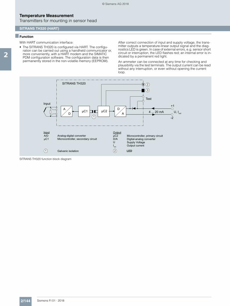
2/144 Siemens FI 01 · 2018
Temperature MeasurementTransmitters for mounting in sensor head
SITRANS TH320 (HART)
2
■ Function
With HART communication interface:• The SITRANS TH320 is configured via HART. The configu-
ration can be carried out using a handheld communicator or, more conveniently, with a HART modem and the SIMATIC PDM configuration software. The configuration data is then permanently stored in the non-volatile memory (EEPROM).
After correct connection of input and supply voltage, the trans-mitter outputs a temperature-linear output signal and the diag-nostics LED is green. In case of external errors, e.g. sensor short circuit or interruption, the LED flashes red; an internal error is in-dicated by a permanent red light.
An ammeter can be connected at any time for checking and plausibility via the test terminals. The output current can be read without any interruption, or even without opening the current loop.
SITRANS TH320 function block diagram
1
1
2
2
3
Input
Galvanic isolation LED
OutputMicrocontroller, primary circuitDigital-analog converterSupply VoltageOutput current
Analog-digital converterMicrocontroller, secondary circuit
Input
+1
-2
μC1 μC2
Test
4 ... 20 mA U, Iout
SITRANS TH320
DA
AD
A/DμC1
μC2D/AUIout
LED
© Siemens AG 2018

2/145Siemens FI 01 · 2018
Temperature MeasurementTransmitters for mounting in sensor head
SITRANS TH320 (HART)
2
■ Technical specifications
General
Supply voltage1) 2)
• Without explosion protection (non-Ex)
7.5 ... 48 V DC
• with explosion protection (Ex i) 7.5 ... 30 V DC
Additional minimum supply voltage when using test terminals
0.8 V
Maximum power loss 850 mW
Minimum load resistance at supply voltage > 37 V
(Vsupply - 37 V)/23 mA
Insulation voltage, test/operation• Without explosion protection (non-
Ex)2.5 kV AC/55 V AC
• with explosion protection (Ex i) 2.5 kV AC/42 V AC
Polarity protection All inputs and outputs
Write protection Open circuits or software
Warming-up time < 5 min
Starting time < 2.75 s
Programming HART
Signal-to-noise ratio > 60 dB
Long-term stability Better than:• ± 0.05% of measuring span/year• ± 0.18% of measuring span/5 years
Response time 4 ... 20 mA: 55 ms
HART: 75 ms (typically 70 ms)
Programmable damping 0 ... 60 s
Signal dynamic• Input 24 bit• Output 18 bit
Influence of change in supply voltage < 0.005% of measuring span/V DC
Input
Resistance thermometer (RTD)
Input type• Pt10 ... 10000 • IEC 60751
• JIS C 1604-8• GOST 6651_2009• Callendar-Van Dusen
• Ni10 ... 10000 • DIN 43760-1987• GOST 6651-2009 / OIML R84:2003
• Cu5 ... 1000 • Edison Copper Winding No. 15• GOST 6651-2009 / OIML R84:2003
Type of connection 2-wire, 3-wire or 4-wire
Line resistance per wire Max. 50
Input current < 0.15 mA
Effect of the line resistance (with 3-wire and 4-wire connections)
< 0.002 /
Cable, wire-wire capacity• Pt1000, Pt10000 (IEC 60751 and
JIS C 1604-8)Max. 30 nF
• All other input types Max. 50 nF
Fault detection, programmable None, short-circuited, defective, short-circuited or defective
Note
When the low limit for the configured input type is below the constant detection limit for short-circuited inputs, the detection of short circuits is disabled regardless of the configu-ration of the fault detection.
Detection limit for short-circuited input 15
Fault detection time (RTD) 75 ms (typically 70 ms)
Fault detection time (for 3-wire and 4-wire)
2000 ms
Thermocouples (TC)
Input type• B IEC 60584-1• E IEC 60584-1• J IEC 60584-1• K IEC 60584-1• L DIN 43710• Lr GOST 3044-84• N IEC 60584-1• R IEC 60584-1• S IEC 60584-1• T IEC 60584-1• U DIN 43710• W3 ASTM E988-96• W5 ASTM E988-96• LR GOST 3044-84
Cold junction compensation (CJC) Constant, internal or external over Pt100 or Ni100 RTD
• Temperature range internal CJC -50 ... +100 °C (-+58 ... +212 °F)• Connection external CJC 2-wire or 3-wire• External CJC, line resistance per
wire (for 3-wire and 4-wire connec-tions)
50
• Effect of the line resistance (with 3-wire and 4-wire connections)
< 0.002 /
• Input current external CJC < 0.15 mA• Temperature range external CJC -50 ... +135 °C (-58 ... +275 °F)• Cable, wire-wire capacity Max. 50 nF• Total line resistance Max. 10 k• Fault detection, programmable None, short-circuited, defective,
short-circuited or defective
Note
The short-circuited fault detection only applies to the CJC input.
• Fault detection time (TC) 75 ms (typically 70 ms)• Fault detection time, external CJC
(for 3-wire and 4-wire) 2000 ms
Linear resistance
Input range 0 ... 100 k
Minimum measuring span 25
Type of connection 2-wire, 3-wire or 4-wire
Line resistance per wire Max. 50
Input current < 0.15 mA
Effect of the line resistance (with 3-wire and 4-wire connections)
< 0.002 /
Cable, wire-wire capacity• R > 400 Max. 30 nF• R 400 Max. 50 nF
Fault detection, programmable None, defective
Potentiometers
Input range 0 ... 100 k
Minimum measuring span 25
Type of connection 2-wire, 3-wire or 4-wire
Line resistance per wire Max. 50
Input current < 0.15 mA
Effect of the line resistance (with 4-wire and 5-wire connections)
< 0.002 /
Cable, wire-wire capacity• R > 400 Max. 30 nF• R 400 Max. 50 nF
© Siemens AG 2018

2/146 Siemens FI 01 · 2018
Temperature MeasurementTransmitters for mounting in sensor head
SITRANS TH320 (HART)
2
1) Note that the minimum supply voltage must correspond to the value mea-sured at the terminals of the SITRANS TH320.All external voltage drops must be taken into consideration.
2) Protect the device from overvoltage with the help of a suitable power sup-ply or suitable overvoltage protection equipment.
3) Additional available certificates are listed on the Internet athttp://www.siemens.com/processinstrumentation/certificates
Fault detection, programmable None, short-circuited, defective, short-circuited or defective
Note
When the configured potentiometer size is below the constant detection limit for short-circuited inputs, the detection of short circuits is disabled regardless of the configuration of the fault detection.
Detection limit for short-circuited input 15
Fault detection time, wiper arm (no short-circuit detection)
75 ms (typically 70 ms)
Fault detection time, element 2000 ms
Fault detection time (for 4-wire and 5-wire)
2000 ms
Voltage input
Measuring range• Unipolar -100 ... 1700 mV• Bipolar -800 ... +800 mV
Minimum measuring span 2.5 mV
Input resistance 10 M
Cable, wire-wire capacity• Input range: -100 ... 1700 mV Max. 30 nF• Input range: -20 ... 100 mV Max. 50 nF
Fault detection, programmable None, defective
Fault detection time 75 ms (typically 70 ms)
Output and HART communication
Normal range, programmable 3.8 ... 20.5 mA/20.5 ... 3.8 mA
Extended range (output limits), pro-grammable
3.5 ... 23 mA/23 ... 3.5 mA
Programmable input/output limits• Fault current Enable/disable• Fault current setting 3.5 ... 23 mA
Update time 10 ms
Load (with current output) (VSupply - 7.5)/0.023
Load stability < 0.01% of meas. span/100 (measuring span = currently selected range)
Input fault detection, programmable(detection of input short circuits is ignored with TC and voltage inputs)
3.5 ... 23 mA
NAMUR NE43 Upscale > 21 mA
NAMUR NE43 Downscale < 3.6 mA
HART protocol versions HART 7
Measuring accuracy
Input accuracy See "Input accuracy" table
Output accuracy See "Output accuracy" table
Rated conditions
Ambient temperature (operation)• Standard -50 ... +85 °C (-58 ... +185 °F)• SIL -40 ... +80 °C (-40 ... +176 °F)
Storage temperature -50 ... +85 °C (-58 ... +185 °F)
Calibration temperature 24 °C ±1.0 °C (75.2 °F ±1.8 °F)
Relative humidity < 99% (no condensation)
Degree of protection• Enclosure of the transmitter IP68• Terminals IP00
Design
Weight 50 g (0.11 lb)
Maximum cable cross-section 1 x 1.5 mm² (stranded wire)
Tightening torque for clamping screws
0.4 Nm
Vibrations IEC 60068-2-6• 2 ... 25 Hz ± 1.6 mm (0.07 inch)• 25 ... 100 Hz ± 4 g
Certificates and approvals
Explosion protection ATEX/IECEx and others
Certificates 3) DEKRA 17ATEX0116 X
IECEx DEK 17.0054X
A5E43700604A-2018X
"Intrinsic safety ia/ib" type of protec-tion
For use in Zone 0, 1, 2, 20, 21, 22
• ATEX II 1 G Ex ia IIC T6 ... T4 GaII 2(1) G Ex ib [ia Ga] IIC T6 ... T4 GbII 1 D Ex ia IIIC DaI M1 Ex ia I Ma
• IECEx and others Ex ia IIC T6 ... T4 GaEx ib [ia Ga] IIC T6 ... T4 GbEx ia IIIC DaEx ia I Ma
"Intrinsic safety ic" type of protection For use in Zones 2 and 22• ATEX II 2 G Ex ic IIC T6…T4 Gc
II 2 D Ex ic IIIC Dc• IECEx and others Ex ic IIC T6 ... T4 Gc
Ex ic IIIC Dc
"Non-sparking/increased safety nA/ec" type of protection
For use in Zones 2 and 22
• ATEX II 2 G Ex nA IIC T6…T4 GcII 2 G Ex ec IIC T6…T4 Gc
• IECEx and others Ex nA IIC T6 ... T4 GcEx ec IIC T6 ... T4 Gc
Explosion protection CSA /FM for Canada and USA
Certificates CSA 1861385FM18CA0024FM18US0046
"Intrinsic safety ia" type of protection IS, CL I, Div 1, GP ABCD, T6 ... T4
Ex ia IIC T6 … T4 GaAEx ia IIC T6 … T4 Ga or:
Ex ib [ia Ga] IIC T6…T4 GbAEx ib [ia Ga] IIC T6…T4 Gb
"Non incendive field wiring NIFW" type of protection
NIFW, CL I, Div 2, GP ABCD T6 ... T4
"Non incendive NI" type of protection NI, CL I, Div 2, GP ABCD T6...T4Ex nA IIC T6 ... T4 GcAEx nA IIC T6 ... T4 Gc
© Siemens AG 2018

2/147Siemens FI 01 · 2018
Temperature MeasurementTransmitters for mounting in sensor head
SITRANS TH320 (HART)
2
Measuring ranges/Minimum measuring span
RTD
TC
Input accuracy
Basic values
Input type Standard Measuring range in °C (°F) 0 in °C-1 (°F-1) Minimum measuring span in °C (°F)
Pt10 ... 10000 IEC 60751 -200 ... +850 (-328 ... +1562) 0.003851 (0.002139) 10 (50)
JIS C 1604-8 -200 ... +649 (-328 ... +1200) 0.003916 (0.002176) 10 (50)
GOST 6651_2009 -200 ... +850 (-328 ... +1562) 0.003910 (0.002172) 10 (50)
Callendar-Van Dusen -200 ... +850 (-328 ... +1562) - 10 (50)
Ni10 ... 10000 DIN 43760-1987 -60 ... +250 (-76 ... +482) 0.006180 (0.003433) 10 (50)
GOST 6651-2009 / OIML R84:2003
-60 ... +180 (-76 ... +356) 0.006170 (0.003428) 10 (50)
Cu5 ... 1000 Edison Copper Winding No. 15
-200 ... +260 (-328 ... +500) 0.004270 (0.002372) 100 (212)
GOST 6651-2009 / OIML R84:2003
-180 ... +200 (-292 ... +392) 0.004280 (0.002378) 100 (212)
GOST 6651-94 -50 ... +200 (-58 ... +392) 0.004260 (0.002367) 100 (212)
Input type Standard Measuring range in °C (°F) Minimum measuring span in °C (°F)
B IEC 60584-1 0 (85) ... 1 820 (32 (185) ... 3 308) 100 (212)
E IEC 60584-1 -200 ... +1 000 (-392 ... +1 832) 50 (122)
J IEC 60584-1 -100 ... +1200 (-212 ... +2192) 50 (122)
K IEC 60584-1 -180 ... +1372 (-356 ... +2502) 50 (122)
L DIN 43710 -200 ... +900 (-392 ... +1652) 50 (122)
Lr GOST 3044-84 -200 ... +800 (-392 ... +1472) 50 (122)
N IEC 60584-1 -180 ... +1300 (-356 ... +2372) 50 (122)
R IEC 60584-1 -50 ... +1760 (-122 ... +3200) 100 (212)
S IEC 60584-1 -50 ... +1760 (-122 ... +3200) 100 (212)
T IEC 60584-1 -200 ... +400 (-392 ... +752) 50 (122)
U DIN 43710 -200 ... +600 (-392 ... +1112) 50 (122)
W3 ASTM E988-96 0 ... 2300 (32 ... 4172) 100 (212)
W5 ASTM E988-96 0 ... 2300 (32 ... 4172) 100 (212)
LR GOST 3044-84 -200 ... +800 (-392 ... +1472) 50 (122)
Input type Basic accuracy Temperature coefficient1)
RTD
Pt10 ±0.8 °C (1.44 °F) ±0.020 °C/°C (°F/°F)
Pt20 ±0.4 °C (0.72 °F) ±0.010 °C/°C (°F/°F)
Pt50 ±0.16 °C (0.288 °F) ±0.004 °C/°C (°F/°F)
Pt100 ±0.04 °C (0.072 °F) ±0.002 °C/°C (°F/°F)
Pt200 ±0.08 °C (0.144 °F) ±0.002 °C/°C (°F/°F)
Pt500 Tmax. < 180 °C (356 °F) = ±0.08 °C (0.144 °F)
Tmax. < 180 °C (356 °F) = ±0.16 °C (0.288 °F)
±0.002 °C/°C (°F/°F)
Pt1000 ±0.08 °C (0.144 °F) ±0.002 °C/°C (°F/°F)
Pt2000 Tmax. < 300 °C (572 °F) = ±0.08 °C (0.144 °F)
Tmax. < 300 °C (572 °F) = ±0.4 °C (0.72 °F)
±0.002 °C/°C (°F/°F)
Pt10000 ±0.16 °C (0.288 °F) ±0.002 °C/°C (°F/°F)
Pt x Largest tolerance of neighboring points Largest temperature coefficient of neighboring points
Ni10 ±1.6 °C (2.88 °F) ±0.020 °C/°C (°F/°F)
Ni20 ±0.8 °C (1.44 °F) ±0.010 °C/°C (°F/°F)
Ni50 ±0.32 °C (0.576 °F) ±0.004 °C/°C (°F/°F)
Ni100 ±0.16 °C (0.288 °F) ±0.002 °C/°C (°F/°F)
Ni120 ±0.16 °C (0.288 °F) ±0.002 °C/°C (°F/°F)
Ni200 ±0.16 °C (0.288 °F) ±0.002 °C/°C (°F/°F)
Ni500 ±0.16 °C (0.288 °F) ±0.002 °C/°C (°F/°F)
Ni1000 ±0.16 °C (0.288 °F) ±0.002 °C/°C (°F/°F)
Ni2000 ±0.16 °C (0.288 °F) ±0.002 °C/°C (°F/°F)
© Siemens AG 2018

2/148 Siemens FI 01 · 2018
Temperature MeasurementTransmitters for mounting in sensor head
SITRANS TH320 (HART)
2
1) Temperature coefficients correspond to the specified values or 0.002% of the input span, depending on which value is greater.
2) Accuracy of the specification range > 400 °C (752 °F)3) Accuracy of the specification range > 160 °C (320 °F) < 400 °C (752 °F)4) Accuracy of the specification range > 85 °C (185 °F) < 160 °C (320 °F)5) Accuracy of the specification range > 85 °C (185 °F)
Output accuracy
Ni10000 ±0.32 °C (0.576 °F) ±0.002 °C/°C (°F/°F)
Ni x Largest tolerance of neighboring points Largest temperature coefficient of neighboring points
Cu5 ±1.6 °C (2.88 °F) ±0.040 °C/°C (°F/°F)
Cu10 ±0.8 °C (1.44 °F) ±0.020 °C/°C (°F/°F)
Cu20 ±0.4 °C (0.72 °F) ±0.010 °C/°C (°F/°F)
Cu50 ±0.16 °C (0.288 °F) ±0.004 °C/°C (°F/°F)
Cu100 ±0.08 °C (0.144 °F) ±0.002 °C/°C (°F/°F)
Cu200 ±0.08 °C (0.144 °F) ±0.002 °C/°C (°F/°F)
Cu500 ±0.16 °C (0.288 °F) ±0.002 °C/°C (°F/°F)
Cu1000 ±0.08 °C (0.144 °F) ±0.002 °C/°C (°F/°F)
Cu x Largest tolerance of neighboring points Largest temperature coefficient of neighboring points
Linear resistance
0 ... 400 ±40 m ±2 m/°C (1.11 m/°F)
0 ... 100 k ±4 ±0.2 /°C (0.11 /°F)
Potentiometers
0 ... 100% < 0.05% < ± 0.005%
Voltage input
mV: -20 ... 100 mV ±5 V ±0.2 V/°C (0.11 V/°F)
mV: -100 ... 1700 mV ±0.1 mV ±36 V/°C (20 V/°F)
mV: ± 800 mV ±0.1 mV ±32 V/°C (17.8 V/°F)
TC
E ±0.2 °C (0.36 °F) ±0.025 °C/°C (°F/°F)
J ±0.25 °C (0.45 °F) ±0.025 °C/°C (°F/°F)
K ±0.25 °C (0.45 °F) ±0.025 °C/°C (°F/°F)
L ±0.35 °C (0.63 °F) ±0.025 °C/°C (°F/°F)
N ±0.4 °C (0.72 °F) ±0.025 °C/°C (°F/°F)
T ±0.25 °C (0.45 °F) ±0.025 °C/°C (°F/°F)
U < 0 °C (32 °F) ±0.8 °C (1.44 °F)
0 °C (32 °F) ±0.4 °C (0.72 °F)
±0.025 °C/°C (°F/°F)
Lr ±0.2 °C (0.36 °F) ±0.1 °C/°C (°F/°F)
R < 200 °C (392 °F) ±0.5 °C (0.9 °F)
200 °C (392 °F) ±1 °C (1.8 °F)
±0.1 °C/°C (°F/°F)
S < 200 °C (392 °F) ±0.5 °C (0.9 °F)
200 °C (392 °F) ±1 °C (1.8 °F)
±0.1 °C/°C (°F/°F)
W3 ±0.6 °C (1.08 °F) ±0.1 °C/°C (°F/°F)
W5 ±0.4 °C (0.72 °F) ±0.1 °C/°C (°F/°F)
B2) ±1 °C (1.8 °F) ±0.1 °C/°C (°F/°F)
B3) ±3 °C (5.4 °F) ±0.1 °C/°C (°F/°F)
B4) ±8 °C (14.4 °F) ±0.8 °C/°C (°F/°F)
B5) Not specified Not specified
CJC (internal) ±0.5 °C (0.9 °F) Included in basic accuracy
CJC (external) ±0.08 °C (0.144 °F) ±0.002 °C/°C (°F/°F)
Input type Basic accuracy Temperature coefficient1)
Output type Basic accuracy Temperature coefficient
Analog output ±1.6 A (0.01% of the full output span)
±0.48 A/K ( ±0.003% of the full output span/K)
© Siemens AG 2018

2/149Siemens FI 01 · 2018
Temperature MeasurementTransmitters for mounting in sensor head
SITRANS TH320 (HART)
2
■ Selection and ordering data
Article No.
Temperature transmitterSITRANS TH320 with 1 input
7NG031
7 - 77777 - 0777
Click on the Article no. for the online configuration in the PIA Life Cycle Portal.
Communication
With HART 0
Primary value output
Input 1 0
Input 1, type
RTD• Pt100 (IEC), 3-wire B• Pt100 (IEC), 4-wire C• Pt1000 (IEC), 3-wire D• Pt1000 (IEC), 4-wire E
TC• Type B F• Type E G• Type J H• Type K J• Type L K• Type N L• Type R N• Type S P• Type T Q
Potentiometer, 4-wire R
Input 1, type customer-specific
Define customer-specific input configurations in V options
Y
Input 2, type
Without input 2 A
CJC configuration for TC
Without CJC 0
Internal CJC 1
External CJC Pt100 (IEC), 2-wire, define line resis-tance value in option Y53
2
External CJC Pt100 (IEC), 3-wire 3
External CJC Ni100 (DIN), 2-wire, define line resis-tance value in option Y53
5
External CJC Ni100 (DIN), 3-wire 6
Materials not in contact with media
None 0
Type of protection
General safety (non-Ex);CE, RCM, FM, CSA, KCC
A
Ex i, Ex nA (ec) (Zone)/IS, NIFW, NI (Division); ATEX, IECEx, CSA, FM, NEPSI
N
Electrical connection/cable entry
None A
Local HMI
Without display 0
Options Order code
Add "-Z" to article no. and specify order code.
Certificates for functional safety
Functional safety SIL2/3 (IEC 61508) C20
Special features of enclosure/packaging
Without labeling of the measuring range on the TAG label D41
Jumper plug set on device for write protection D81
Jumper plug set on device for fault current > 21 mA (instead of < 3.6 mA) (only non-SIL)
D82
Input 1: TC
Type C W5 V01
Type D W3 V02
Type U V03
Type Lr V04
Input 1: RTD
Pt x (IEC), 3-wire, define RTD factor x in option Y21 V61
Pt x (IEC), 4-wire, define RTD factor x in option Y21 V62
Pt x (JIS C1604-81), 3-wire, define RTD factor x in option Y21
V64
Pt x (JIS C1604-81), 4-wire, define RTD factor x in option Y21
V65
Pt x (GOST 6651-2009), 3-wire, define RTD factor x in option Y21
V67
Pt x (GOST 6651-2009), 4-wire, define RTD factor x in option Y21
V68
Ni x (DIN 43760-87), 3-wire, define RTD factor x in option Y21
V70
Ni x (DIN 43760-87), 4-wire, define RTD factor x in option Y21
V71
Ni x (GOST 6651-2009), 3-wire, define RTD factor x in option Y21
V73
Ni x (GOST 6651-2009), 4-wire, define RTD factor x in option Y21
V74
Cu x (ECW-15), 3-wire, define RTD factor x in option Y21 V76
Cu x (ECW-15), 4-wire, define RTD factor x in option Y21 V77
Cu x (GOST 6651-94), 2-wire, define line resistance value in option Y51 and RTD factor x in option Y21
V78
Cu x (GOST 6651-94), 3-wire, define RTD factor x in option Y21
V79
Cu x (GOST 6651-94), 4-wire, define RTD factor x in option Y21
V80
Cu x (GOST 6651-2009), 3-wire, define RTD factor x in option Y21
V82
Cu x (GOST 6651-2009), 4-wire, define RTD factor x in option Y21
V83
© Siemens AG 2018

2/150 Siemens FI 01 · 2018
Temperature MeasurementTransmitters for mounting in sensor head
SITRANS TH320 (HART)
2
■ Selection and ordering data
Ordering example
7NG0310-0BA00-0AA0-Z Y01
Y01: -10 ... +100 °C
Factory setting• Pt100 (IEC 60751) with 3-wire system• Measuring range: 0 ... 100 °C (32 ... 212 °F)• Fault current
- Input circuit wire break: 22.8 mA- Input circuit short circuit: 22.4 mA- Input monitoring wire break and short-circuit
• No trimming of input and output (offset)• Damping 0.0 s
■ Dimensional drawings
SITRANS TH320, dimensions and pin assignment, dimensions in mm (inch)
Customer-specific device settings Order code
Add "-Z" to article no., specify order code and plain text or drop-down list selection.
Measuring range setting temperature input: Start of scale value (max. 5 characters), full scale value (max. 5 characters), unit (°C, °F, °Ra, K)
Y01
Plant designation (TAG, device parameters, max. 32 characters)
Y15
Measuring point message (device message and device parameters, max. 32 characters)
Y16
Input 1: RTD factor; e.g. factor "200" = Pt200 Y21
Accessories Article No.
Further accessories for assembly, connection and transmitter configu-ration, see page 2/237.
HART modem
With USB interface
7MF4997-1DB
SIMATIC PDM parameterization software
See Catalog FI 01 section 8
DIN rail adapter for temperature transmitter for head mounting
(Quantity delivered: 5 units)
7NG3092-8KA
Connecting cable
4-wire, 200 mm, for input connec-tion with temperature transformers for head mounting in the high hinged cover (set with 5 units)
7NG3092-8KC
TEST -
21
22
23
24
25
5 2
22
2422
23 211
Test terminal
Mounting screw M4
LED
20,2
(0.8
)
Output terminals
Input terminals
1(+) and 2(-)
3, 4, 5 and 6
Internal diameter of center hole 6.3 (0.25)
Lock washer DIN 6799 - 3.2 A2
TEST + 12
6 5 43
EXT
33 (1.3)Ø 44 (1.73)
© Siemens AG 2018

2/151Siemens FI 01 · 2018
Temperature MeasurementTransmitters for mounting in sensor head
SITRANS TH320 (HART)
2
■ Circuit diagrams
Connections
Input connection
SITRANS TH320, input connection assignment
Output connection
SITRANS TH320, output connection assignment
2-wire, 3-wire or 4-wire RTD or linear resistance
Voltage input(unipolar or bipolar)
3-wire or 4-wire potentiometer
TC (internal CJC orexternal 2-wire or 3-wire CJC)
4I1
45
6
9
87
3
I134
45
6
9
8 7
3
+
45
6
9
87
3
+CJC 3
45
6
9
87
3
mA
+
-+ 21
TEST-
EXTTEST
© Siemens AG 2018

2/152 Siemens FI 01 · 2018
Temperature MeasurementTransmitters for mounting in sensor head
SITRANS TH400 fieldbus transmitter
2
■ Overview
SITRANS TH400 fieldbus transmitters
Versions:• For FOUNDATION fieldbus• For PROFIBUS PA
The SITRANS TH400 temperature transmitter is a small field bus transmitter for mounting in the connection head of form B. Exten-sive functionality enables the temperature transmitter to be pre-cisely adapted to the plant’s requirements. Operation is very simple in spite of the numerous setting options. Thanks to its uni-versal concept it can be used in all industries and is easy to in-tegrate in the context of Totally Integrated Automation applica-tions.
Transmitters of the "intrinsically safe" type of protection can be in-stalled within potentially explosive atmospheres. The devices comply with the Directive 2014/34/EU (ATEX), as well as FM and CSA regulations.
Installing SITRANS TH400 in temperature sensors turns them into complete, bus-capable measuring points; compact - and in a single device.
■ Application
• Linearized temperature measurement with resistance ther-mometers or thermal elements
• Differential, mean-value or redundant temperature measure-ment with resistance thermometers or thermal elements
• Linear resistance and bipolar millivolt measurements• Differential, mean-value or redundant resistance and bipolar
millivolt measurements
■ Function
Features• Mounting in connection head, type B, to DIN 43729, or larger• Polarity-neutral bus connection• 24-bit analog-digital converter for high resolution• Electrically isolated• Intrinsically-safe version for use in potentially explosive areas• Special characteristic• Sensor redundance
With PROFIBUS PA communication• Function blocks: 2 x analog
With FOUNDATION fieldbus communication• Function blocks: 2 x analog and 1 x PID• Functionality: Basic or LAS
Mode of operation
The following function diagram explains the mode of operation of the transmitter.
The only difference between the two versions of the SITRANS TH400 (7NG3214-... and 7NG3215-...) is the type of fieldbus protocol used (PROFIBUS PA or FOUNDATION fieldbus).
SITRANS TH400, function diagram
Optional inputs:- Resistance thermometer- Thermocouple- mV sensor- Resistance-based sensors
Input 1
Input 2
TransformerInput 1Input 2DifferentialMean valueRedundancyTerminal temperatureEngineering units Diagnostic functionsTable linearizationPolynomial linearizationProcess calibration
A/D converter
Complex configurationCorrection coefficientFactory settings
- PROFIBUS protocol (7NG3214) or- Foundation Fieldbus protocol (7NG3215)
Bus connection
Ex
pow
er c
ircui
t
Electrically isolated
Internal Pt100
Communication
EEPROM
CPU
6
5
4
32
1
© Siemens AG 2018

2/153Siemens FI 01 · 2018
Temperature MeasurementTransmitters for mounting in sensor head
SITRANS TH400 fieldbus transmitter
2
System communication
SITRANS TH400, communication interface
■ Technical specifications
Input
Analog-to-digital conversion
• Measurement rate < 50 ms
• Resolution 24-bit
Resistance thermometer
Pt25 ... Pt1000 to IEC 60751/JIS C 1604
• Measuring range -200 ... +850 °C (-328 ... +1562 °F)
Ni25 ... Ni1000 to DIN 43760
• Measuring range -60 ... +250 °C (-76 ... +482 °F)
Cu10 ... Cu1000, = 0.00427
• Measuring range -50 ... +200 °C (-58 ... +392 °F)
Line resistance per sensor cable Max. 50
Sensor current Nominal 0.2 mA
Sensor fault detection
• Sensor break detection Yes
• Sensor short-circuit detection Yes, < 15
Resistance-based sensors
Measuring range 0 ... 10 k
Line resistance per sensor cable Max. 50
Sensor current Nominal 0.2 mA
Sensor fault detection
• Sensor break detection Yes
• Sensor short-circuit detection Yes, < 15
s
s
Output:
Bus terminator
Bus terminator
Segment coupler
Segment coupler
Bus connection
Bus connection
PROFIBUS PA
FOUNDATION Fieldbus
SITRANS TH400 FF
SITRANS TH400 PA
12
12
Thermocouple
to IEC 584 Measuring range
• Type B 400 .. +1820 °C (752 ... 3308 °F)
• Type E -100 ... +1000 °C (-148 ... +1832 °F)
• Type J -100 ... +1000 °C (-148 ... +1832 °F)
• Type K -100 ... +1200 °C (-148 ... +2192 °F)
• Type N -180 ... +1300 °C (-292 ... +2372 °F)
• Type R -50 ... +1760 °C (-58 ... +3200 °F)
• Type S -50 ... +1760 °C (-58 ... +3200 °F)
• Type T -200 ... +400 °C (-328 ... +752 °F)
to DIN 43710
• Type L -200 ... +900 °C (-328 ... +1652 °F)
• Type U -200 ... +600 °C (-328 ... +1112 °F)
to ASTM E988-90
• Type W3 0 ... 2300 °C (32 ... +4172 °F)
• Type W5 0 ... 2300 °C (32 ... +4172 °F)
External cold junction compensa-tion
-40 ... +135 °C (-40 ... +275 °F)
Sensor fault detection
• Sensor break detection Yes
• Sensor short-circuit detection Yes, < 3 mV
• Sensor current in the event of open-circuit monitoring
4 A
mV sensor - voltage input
Measuring range -800 ... +800 mV
Input resistance 10 M
Output
Filter time (programmable) 0 ... 60 s
Update time < 400 ms
Measuring accuracy
Accuracy is defined as the higher value of general values and basic values.
General values
Type of input Absolute accu-racy
Temperature coefficient
All 0.05 % of the measured value
0.002 % of the measured value/°C
Basic values
Type of input Basic accuracy Temperature coefficient
Pt100 and Pt1000 0.1 °C 0.002 °C/°C
Ni100 0.15 °C 0.002 °C/°C
Cu10 1.3 °C 0.02 °C/°C
Resistance-based sensors 0.05 0.002 /°C
Voltage source 10 V 0.2 % V/°C
Thermocouple, type:E, J, K, L, N, T, U
0.5 °C 0.01 °C/°C
Thermocouple, type:B, R, S, W3, W5
1 °C 0.025 °C/°C
Cold junction compensation 0.5 °C
Reference conditions
Warming-up time 30 s
Signal-to-noise ratio Min. 60 dB
Calibration condition 20 ... 28 °C (68 ... 82 °F)
© Siemens AG 2018

2/154 Siemens FI 01 · 2018
Temperature MeasurementTransmitters for mounting in sensor head
SITRANS TH400 fieldbus transmitter
2
Conditions of use
Ambient conditions
Permissible ambient temperature -40 ... +85 °C (-40 ... +185 °F)
Permissible storage temperature -40 ... +85 °C (-40 ... +185 °F)
Relative humidity 98 %, with condensation
Insulation resistance
• Test voltage 500 V AC for 60 s
Mechanical testing
• Vibrations (DIN class B) to IEC 60068-2-6 andIEC 60068-2-644 g/2 ... 100 Hz
Electromagnetic compatibility
EMC noise voltage influence < 0.1 % of span
Extended EMC noise immunity:NAMUR NE 21, criterion A, Burst
< 1 % of span
EMC 2014/30/EU Emission and Noise Immunity to
EN 61326
Construction
Material Molded plastic
Weight 55 g (0.12 lb)
Dimensions See Dimensional drawings
Cross-section of cables Max. 2.5 mm2 (AWG 13)
Degree of protection
• Transmitter enclosure IP40
• Terminal IP00
Auxiliary power
Power supply
• Standard, Ex "nA", Ex "nL", NI 9.0 ... 32 V DC
• ATEX, FM, UL and CSA 9.0 ... 30 V DC
• In FISCO/FNICO installations 9.0 ... 17.5 V DC
Power consumption < 11 mA
Max. increase in power consump-tion in the event of a fault
< 7 mA
Certificates and approvals
Explosion protection ATEX
EC type test certificate KEMA 06 ATEX 0264
• "Intrinsic safety" type of protection II 1 G Ex ia IIC T4...T6II 2(1) G Ex ib[ia] IIC T4...T6II 1 D Ex iaD
EC type test certificate KEMA 06 ATEX 0263 X
• Type of protection for "equipment is non-arcing"
II 3 GD Ex nA[nL] IIC T4...T6II 3 GD Ex nL IIC T4...T6II 3 GD Ex nA[ic] IIC T4...T6II 3 GD Ex ic IIC T4...T6
Explosion protection: FM for USA
• FM approval FM 3027985
• Degree of protection • IS Class I, Div 1, Groups A, B, C, D T4/T5/T6, FISCO
• IS Class I, Zone 0, AEx ia, IIC T4/T5/T6, FISCO
• NI Class I, Div 2, Groups A, B, C, D T4/T5/T6, FNICO
Explosion protection CSA for Canada
• CSA approval CSA 1861385
• Degree of protection • IS Class I, Div 1, Groups A, B, C, D T4/T5/T6
• Ex ia IIC T4/T5/T6 and Ex ib [ia] IIC T4/T5/T6
• NI Class I, Div 2, Groups A, B, C, D T4/T5/T6
• Ex nA II T4/T5/T6
Other certificates EAC Ex(GOST), NEPSI, IECEx
Communication
Parameterization interface
• PROFIBUS PA connection
- Protocol Profile 3.0
- Address (for delivery) 126
• FOUNDATION fieldbus connec-tion
- Protocol FF protocol
- Functionality Basic or LAS
- Version ITK 4.6
- Function blocks 2 x analog and 1 x PID
Factory setting
only for SITRANS TH400 PA
Sensor Pt100 (IEC)
Type of connection 3-wire circuit
Unit °C
Failure mode Last valid value
Filter time 0 s
PA address 126
PROFIBUS Ident No. Manufacturer-specific
only for SITRANS TH400 FF
Sensor Pt100 (IEC)
Type of connection 3-wire circuit
Unit °C
Failure mode Last valid value
Filter time 0 s
Node address 22
© Siemens AG 2018

2/155Siemens FI 01 · 2018
Temperature MeasurementTransmitters for mounting in sensor head
SITRANS TH400 fieldbus transmitter
2
■ Selection and Ordering data Article No.
Ordering example 1:
7NG3214-0NN00-Z Y01+Y17+U03Y01: 0...100 °CY17: TICA1234HEAT
Ordering example 2:
7NG3214-0NN00-Z Y01+Y17+Y25+U25Y01: 0...500 °CY17: TICA5678HEATY25: 33
Factory setting: • For SITRANS TH400 PA:
- Pt100 (IEC 751) with 3-wire circuit- Unit: °C- Failure mode: Last valid value- Filter time: 0 s- PA address: 126- PROFIBUS Ident No.: Manufacturer-specific
• For SITRANS TH400 FF: - Pt100 (IEC 751) with 3-wire circuit- Unit: °C- Failure mode: Last valid value- Filter time: 0 s- Node address: 22
Temperature transmitter SITRANS TH400
for installation in connection head, with electrical isolation, order operating instruc-tions separately.
• Bus-compatible to PROFIBUS PA
- No explosion protection or Zone 2/Div 2 to ATEX/FM/CSA/IECEX/NEPSI
7NG3214-0NN00
- With explosion protection "Intrinsically safe to ATEX/FM/CSA/IECEX/NEPSI"
7NG3214-0AN00
• Bus-compatible to FOUNDATION Fieldbus
- No explosion protection or Zone 2/Div 2 to ATEX/FM/CSA/IECEX/NEPSI
7NG3215-0NN00
- With explosion protection "Intrinsically safe to ATEX/FM/CSA/IECEX/NEPSI"
7NG3215-0AN00
Further designs Order code
Please add "-Z" to Article No. and specify Order code(s) and plain text.
With test protocol (5 measuring points) C11
Customer-specific programmingAdd "-Z" to Article No. and specify Order code(s)
Measuring range to be setSpecify in plain text (max. 5 digits):Y01: ... to ... °C, °F
Y011)
Measuring point no. (TAG), max. 8 characters Y172)
Measuring point descriptor,max. 16 characters
Y232)
Measuring point message,max. 32 characters
Y242)
Bus address, specify in plain text Y252)
Pt100 (IEC) 2-wire, RL = 0 U023)
Pt100 (IEC) 3-wire U033)
Pt100 (IEC) 4-wire U043)
Pt1000 (IEC) 2-wire, RL = 0 U12
Pt1000 (IEC) 3-wire U13
Pt1000 (IEC) 4-wire U14
Thermocouple type B U203)4)
Thermocouple type C (W5) U213)4)
Thermocouple type D (W3) U223)4)
Thermocouple type E U233)4)
Thermocouple type J U243)4)
Thermocouple type K U253)4)
Thermocouple type L U263)4)
Thermocouple type N U273)4)
Thermocouple type R U283)4)
Thermocouple type S U293)4)
Thermocouple type T U303)4)
Thermocouple type U U313)4)
With TC: CJC external (Pt100, 3-wire) U41
With TC: CJC external with fixed value, spec-ify in plain text
Y50
Special differing customer-specific program-ming, specify in plain text
Y095)
AccessoriesFurther accessories for assembly, connection and transmitter configuration, see page 2/237.
Article No.
SIMATIC PDM operating software See Chapter 8
DIN rail adapters for head transmitters 7NG3092-8KA
(Quantity delivered: 5 units)
Connecting cable4-wire, 150 mm, for sensor connections when using head transmitters in the high hinged cover (set with 5 units)
7NG3092-8KC
for additional PA components See Catalog IK PI
1) For customer-specific programming for RTD and TC, the start value and the end value of the required measuring span must be specified here.
2) For this selection, Y01 or Y09 must also be selected.3) For this selection, Y01 must also be selected.4) Internal cold junction compensation is selected as the default for TC.5) For customer-specific programming, for example mV and ohm, the start
value and the end value of the required measuring span and the unit must be entered here.
© Siemens AG 2018

2/156 Siemens FI 01 · 2018
Temperature MeasurementTransmitters for mounting in sensor head
SITRANS TH400 fieldbus transmitter
2
■ Dimensional drawings
SITRANS TH400 dimensions in mm (inches) and connections
Mounting on DIN rail
SITRANS TH400, mounting of transmitter on DIN rail
DIN rail adaptor, dimensions in mm (inch)
Terminals 1, 2: fieldbus connectionTerminals 3 ... 6: sensor connection
26.3 (1.04)Ø 6.3 (0.25)
33 (1.3)
Ø 44 (1.73)
M4 x 30
s1 2
54
3 6
+ -3-W
50.5 (1.99)
59.6
(2.3
5)
33 (1.30)14 (0.55)
© Siemens AG 2018
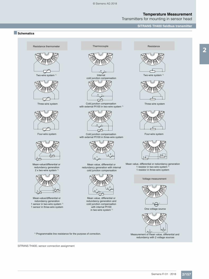
2/157Siemens FI 01 · 2018
Temperature MeasurementTransmitters for mounting in sensor head
SITRANS TH400 fieldbus transmitter
2
■ Schematics
SITRANS TH400, sensor connection assignment
Resistance thermometer ResistanceThermocouple
Voltage measurement
Two-wire system 1)
Three-wire system
Four-wire system
Two-wire system 1)
Three-wire system
Four-wire system
Internal cold junction compensation
Cold junction compensation with external Pt100 in two-wire system 1)
Cold junction compensation with external Pt100 in three-wire system
1) Programmable line resistance for the purpose of correction.
Mean-value/differential or redundancy generation
1 sensor in two-wire system 1)
1 sensor in three-wire system
Mean-value/differential or redundancy generation2 x two-wire system 1)
Mean value, differential or redundancy generation with internal
cold junction compensation
Mean value, differential or redundancy generation and cold junction compensation
with internal Pt100 in two-wire system 1)
Mean value, differential or redundancy generation1 resistor in two-wire system 1)
1 resistor in three-wire system
Measurement of mean value, differential and redundancy with 2 voltage sources
One voltage source
12
12
+ -
+ -
+ -
12
+ -
12
+ - + -
21+ -
+ -
12
+ -+ -
© Siemens AG 2018

2/158 Siemens FI 01 · 2018
Temperature MeasurementTransmitters for mounting in sensor head
SITRANS TH420 (HART)
2
■ Overview
• 2-wire temperature transmitter with HART communication interface
• Mounting in the connection head of the temperature sensor• Universal input for virtually any type of temperature sensor• Connection of two independent input circuits for redundant
operation (high input availability)• Input drift detection• Configurable over HART
■ Benefits
• Compact design• Connection of two independent input circuits for redundant
operation (high input availability)• Flexible mounting and center hole allow you to select your
preferred type of installation• Electrical isolation• Test terminals for ammeter• Diagnostics LED (green/red)• Input monitoring
wire break, short circuit and drift• Self-monitoring• Configuration status stored in EEPROM• SIL2/3 (with order note C20)• Expanded diagnostic functions, such as slave pointer,
operating hours counter, etc.• Special characteristic• Electromagnetic compatibility according to DIN EN 61326
and NE21
■ Application
The SITRANS TH420 transmitter with two inputs can be used in all sectors. Its compact size means that it can be installed in con-nection heads of type B (DIN 43729) or larger. Due to its univer-sal input module, the following sensors and signal sources can be connected in redundant operation (high input availability):• 2 resistance thermometers (2-wire, 3-wire, 4-wire connection)• 2 thermocouples• 2 linear resistors, potentiometer and DC voltage sources
The output signal is a load-independent direct current from 4 to 20 mA in accordance with the input characteristic, superim-posed by the digital HART signal.
The dual input mode also supports drift detection of the inputs, whereby maintenance intervals can be more easily planned.
Transmitters of the "intrinsically safe or Zone 2 increased safety" type of protection can be installed in hazardous areas. The de-vice meets the requirements of the EU Directive 2014/34/EU (ATEX), the FM and CSA regulations as well as other national ap-provals.
© Siemens AG 2018

2/159Siemens FI 01 · 2018
Temperature MeasurementTransmitters for mounting in sensor head
SITRANS TH420 (HART)
2
■ Function
The SITRANS TH420 is configured via HART. The configuration can be carried out using a handheld communicator or, more conveniently, with a HART modem and the SIMATIC PDM config-uration software. The configuration data is then permanently stored in the non-volatile memory (EEPROM).
After correct connection of input and supply voltage, the trans-mitter outputs a temperature-linear output signal and the diag-nostics LED is green. In case of external errors, e.g. sensor short circuit or interruption, the LED flashes red; an internal error is in-dicated by a permanent red light.
An ammeter can be connected at any time for checking and plausibility via the test terminals. The output current can be read without any interruption, or even without opening the current loop.
SITRANS TH420, function block diagram
1
1
2
2
3
3Galvanic isolation
OutputMicrocontroller, primary circuitDigital-analog converterSupply VoltageOutput current
Analog-digital converterMicrocontroller, secondary circuit
Input
Extension port
Input
+1
-2
μC1 μC2
Test
4 ... 20 mA U, Iout
SITRANS TH420
DA
AD
A/DμC1
μC2D/AUIout
LED
© Siemens AG 2018

2/160 Siemens FI 01 · 2018
Temperature MeasurementTransmitters for mounting in sensor head
SITRANS TH420 (HART)
2
■ Technical specifications
General
Supply voltage1) 2)
• Without explosion protection (non-Ex)
7.5 ... 48 V DC
• with explosion protection (Ex i) 7.5 ... 30 V DC
Additional minimum supply voltage when using test terminals
0.8 V
Maximum power loss 850 mW
Minimum load resistance at supply voltage > 37 V
(Vsupply - 37 V)/23 mA
Insulation voltage, test/operation• Without explosion protection (non-
Ex)2.5 kV AC/55 V AC
• with explosion protection (Ex i) 2.5 kV AC/42 V AC
Polarity protection All inputs and outputs
Write protection Open circuits or software
Warming-up time < 5 min
Starting time < 2.75 s
Programming HART
Signal-to-noise ratio > 60 dB
Long-term stability Better than:• ± 0.05% of measuring span/year• ± 0.18% of measuring span/5 years
Response time 75 ms (typically 70 ms)
Programmable damping 0 ... 60 s
Signal dynamic• Input 24 bit• Output 18 bit
Influence of change in supply voltage < 0.005% of measuring span/V DC
Input
Resistance thermometer (RTD)
Input type• Pt10 ... 10000 • IEC 60751
• JIS C 1604-8• GOST 6651_2009• Callendar-Van Dusen
• Ni10 ... 10000 • DIN 43760-1987• GOST 6651-2009 / OIML R84:2003
• Cu5 ... 1000 • Edison Copper Winding No. 15• GOST 6651-2009 / OIML R84:2003
Type of connection 2-wire, 3-wire or 4-wire
Line resistance per wire Max. 50
Input current < 0.15 mA
Effect of the line resistance (with 3-wire and 4-wire connections)
< 0.002 /
Cable, wire-wire capacity• Pt1000, Pt10000 (IEC 60751 and
JIS C 1604-8)Max. 30 nF
• All other input types Max. 50 nF
Fault detection, programmable None, short-circuited, defective, short-circuited or defective
Note
When the low limit for the configured input type is below the constant detection limit for short-circuited inputs, the detection of short circuits is disabled regardless of the configu-ration of the fault detection.
Detection limit for short-circuited input 15
Fault detection time (RTD) 75 ms (typically 70 ms)
Fault detection time (for 3-wire and 4-wire)
2000 ms
Thermocouples (TC)
Input type• B IEC 60584-1• E IEC 60584-1• J IEC 60584-1• K IEC 60584-1• L DIN 43710• Lr GOST 3044-84• N IEC 60584-1• R IEC 60584-1• S IEC 60584-1• T IEC 60584-1• U DIN 43710• W3 ASTM E988-96• W5 ASTM E988-96• LR GOST 3044-84
Cold junction compensation (CJC) Constant, internal or external over Pt100 or Ni100 RTD
• Temperature range internal CJC -50 ... +100 °C (-+58 ... +212 °F)• Connection external CJC 2-wire, 3-wire or 4-wire• External CJC, line resistance per
wire (for 3-wire and 4-wire connec-tions)
50
• Effect of the line resistance (with 3-wire and 4-wire connections)
< 0.002 /
• Input current external CJC < 0.15 mA• Temperature range external CJC -50 ... +135 °C (-58 ... +275 °F)• Cable, wire-wire capacity Max. 50 nF• Total line resistance Max. 10 k• Fault detection, programmable None, short-circuited, defective,
short-circuited or defective
Note
The short-circuited fault detection only applies to the CJC input.
• Fault detection time (TC) 75 ms (typically 70 ms)• Fault detection time, external CJC
(for 3-wire and 4-wire) 2000 ms
Linear resistance
Input range 0 ... 100 k
Minimum measuring span 25
Type of connection 2-wire, 3-wire or 4-wire
Line resistance per wire Max. 50
Input current < 0.15 mA
Effect of the line resistance (with 3-wire and 4-wire connections)
< 0.002 /
Cable, wire-wire capacity• R > 400 Max. 30 nF• R 400 Max. 50 nF
Fault detection, programmable None, defective
Potentiometers
Input range 0 ... 100 k
Minimum measuring span 25
Type of connection 2-wire, 3-wire or 4-wire
Line resistance per wire Max. 50
Input current < 0.15 mA
Effect of the line resistance (with 4-wire and 5-wire connections)
< 0.002 /
Cable, wire-wire capacity• R > 400 Max. 30 nF• R 400 Max. 50 nF
© Siemens AG 2018

2/161Siemens FI 01 · 2018
Temperature MeasurementTransmitters for mounting in sensor head
SITRANS TH420 (HART)
2
1) Note that the minimum supply voltage must correspond to the value mea-sured at the terminals of the SITRANS TH420.All external voltage drops must be taken into consideration.
2) Protect the device from overvoltage with the help of a suitable power sup-ply or suitable overvoltage protection equipment.
3) Additional available certificates are listed on the Internet athttp://www.siemens.com/processinstrumentation/certificates
Fault detection, programmable None, short-circuited, defective, short-circuited or defective
Note
When the configured potentiometer size is below the constant detection limit for short-circuited inputs, the detection of short circuits is disabled regardless of the configuration of the fault detection.
Detection limit for short-circuited input 15
Fault detection time, wiper arm (no short-circuit detection)
75 ms (typically 70 ms)
Fault detection time, element 2000 ms
Fault detection time (for 4-wire and 5-wire)
2000 ms
Voltage input
Measuring range• Unipolar -100 ... 1700 mV• Bipolar -800 ... +800 mV
Minimum measuring span 2.5 mV
Input resistance 10 M
Cable, wire-wire capacity• Input range: -100 ... 1700 mV Max. 30 nF• Input range: -20 ... 100 mV Max. 50 nF
Fault detection, programmable None, defective
Fault detection time 75 ms (typically 70 ms)
Output and HART communication
Normal range, programmable 3.8 ... 20.5 mA/20.5 ... 3.8 mA
Extended range (output limits), pro-grammable
3.5 ... 23 mA/23 ... 3.5 mA
Programmable input/output limits• Fault current Enable/disable• Fault current setting 3.5 ... 23 mA
Update time 10 ms
Load (with current output) (VSupply - 7.5)/0.023
Load stability < 0.01% of meas. span/100 (measuring span = currently selected range)
Input fault detection, programmable(detection of input short circuits is ignored with TC and voltage inputs)
3.5 ... 23 mA
NAMUR NE43 Upscale > 21 mA
NAMUR NE43 Downscale < 3.6 mA
HART protocol versions HART 7
Measuring accuracy
Input accuracy See "Input accuracy" table
Output accuracy See "Output accuracy" table
Rated conditions
Ambient temperature (operation)• Standard -50 ... +85 °C (-58 ... +185 °F)• SIL -40 ... +80 °C (-40 ... +176 °F)
Storage temperature -50 ... +85 °C (-58 ... +185 °F)
Calibration temperature 24 °C ±1.0 °C (75.2 °F ±1.8 °F)
Relative humidity < 99% (no condensation)
Degree of protection• Enclosure of the transmitter IP68• Terminals IP00
Design
Weight 50 g (0.11 lb)
Maximum cable cross-section 1 x 1.5 mm² (stranded wire)
Tightening torque for clamping screws
0.4 Nm
Vibrations IEC 60068-2-6• 2 ... 25 Hz ± 1.6 mm (0.07 inch)• 25 ... 100 Hz ± 4 g
Certificates and approvals
Explosion protection ATEX/IECEx and others
Certificates 3) DEKRA 17ATEX0116 X
IECEx DEK 17.0054X
A5E43700604A-2018X
"Intrinsic safety ia/ib" type of protec-tion
For use in Zone 0, 1, 2, 20, 21, 22
• ATEX II 1 G Ex ia IIC T6 ... T4 GaII 2(1) G Ex ib [ia Ga] IIC T6 ... T4 GbII 1 D Ex ia IIIC DaI M1 Ex ia I Ma
• IECEx and others Ex ia IIC T6 ... T4 GaEx ib [ia Ga] IIC T6 ... T4 GbEx ia IIIC DaEx ia I Ma
"Intrinsic safety ic" type of protection For use in Zones 2 and 22• ATEX II 2 G Ex ic IIC T6…T4 Gc
II 2 D Ex ic IIIC Dc• IECEx and others Ex ic IIC T6 ... T4 Gc
Ex ic IIIC Dc
"Non-sparking/increased safety nA/ec" type of protection
For use in Zones 2 and 22
• ATEX II 2 G Ex nA IIC T6…T4 GcII 2 G Ex ec IIC T6…T4 Gc
• IECEx and others Ex nA IIC T6 ... T4 GcEx ec IIC T6 ... T4 Gc
Explosion protection CSA /FM for Canada and USA
Certificates CSA 1861385FM18CA0024FM18US0046
"Intrinsic safety ia" type of protection IS, CL I, Div 1, GP ABCD, T6 ... T4
Ex ia IIC T6 … T4 GaAEx ia IIC T6 … T4 Ga or:
Ex ib [ia Ga] IIC T6…T4 GbAEx ib [ia Ga] IIC T6…T4 Gb
"Non incendive field wiring NIFW" type of protection
NIFW, CL I, Div 2, GP ABCD T6 ... T4
"Non incendive NI" type of protection NI, CL I, Div 2, GP ABCD T6...T4Ex nA IIC T6 ... T4 GcAEx nA IIC T6 ... T4 Gc
© Siemens AG 2018

2/162 Siemens FI 01 · 2018
Temperature MeasurementTransmitters for mounting in sensor head
SITRANS TH420 (HART)
2
Measuring ranges/Minimum measuring span
RTD
TC
Input accuracy
Basic values
Input type Standard Measuring range in °C (°F) 0 in °C-1 (°F-1) Minimum measuring span in °C (°F)
Pt10 ... 10000 IEC 60751 -200 ... +850 (-328 ... +1562) 0.003851 (0.002139) 10 (50)
JIS C 1604-8 -200 ... +649 (-328 ... +1200) 0.003916 (0.002176) 10 (50)
GOST 6651_2009 -200 ... +850 (-328 ... +1562) 0.003910 (0.002172) 10 (50)
Callendar-Van Dusen -200 ... +850 (-328 ... +1562) - 10 (50)
Ni10 ... 10000 DIN 43760-1987 -60 ... +250 (-76 ... +482) 0.006180 (0.003433) 10 (50)
GOST 6651-2009 / OIML R84:2003
-60 ... +180 (-76 ... +356) 0.006170 (0.003428) 10 (50)
Cu5 ... 1000 Edison Copper Winding No. 15
-200 ... +260 (-328 ... +500) 0.004270 (0.002372) 100 (212)
GOST 6651-2009 / OIML R84:2003
-180 ... +200 (-292 ... +392) 0.004280 (0.002378) 100 (212)
GOST 6651-94 -50 ... +200 (-58 ... +392) 0.004260 (0.002367) 100 (212)
Input type Standard Measuring range in °C (°F) Minimum measuring span in °C (°F)
B IEC 60584-1 0 (85) ... 1 820 (32 (185) ... 3 308) 100 (212)
E IEC 60584-1 -200 ... +1 000 (-392 ... +1 832) 50 (122)
J IEC 60584-1 -100 ... +1200 (-212 ... +2192) 50 (122)
K IEC 60584-1 -180 ... +1372 (-356 ... +2502) 50 (122)
L DIN 43710 -200 ... +900 (-392 ... +1652) 50 (122)
Lr GOST 3044-84 -200 ... +800 (-392 ... +1472) 50 (122)
N IEC 60584-1 -180 ... +1300 (-356 ... +2372) 50 (122)
R IEC 60584-1 -50 ... +1760 (-122 ... +3200) 100 (212)
S IEC 60584-1 -50 ... +1760 (-122 ... +3200) 100 (212)
T IEC 60584-1 -200 ... +400 (-392 ... +752) 50 (122)
U DIN 43710 -200 ... +600 (-392 ... +1112) 50 (122)
W3 ASTM E988-96 0 ... 2300 (32 ... 4172) 100 (212)
W5 ASTM E988-96 0 ... 2300 (32 ... 4172) 100 (212)
LR GOST 3044-84 -200 ... +800 (-392 ... +1472) 50 (122)
Input type Basic accuracy Temperature coefficient1)
RTD
Pt10 ±0.8 °C (1.44 °F) ±0.020 °C/°C (°F/°F)
Pt20 ±0.4 °C (0.72 °F) ±0.010 °C/°C (°F/°F)
Pt50 ±0.16 °C (0.288 °F) ±0.004 °C/°C (°F/°F)
Pt100 ±0.04 °C (0.072 °F) ±0.002 °C/°C (°F/°F)
Pt200 ±0.08 °C (0.144 °F) ±0.002 °C/°C (°F/°F)
Pt500 Tmax. < 180 °C (356 °F) = ±0.08 °C (0.144 °F)
Tmax. < 180 °C (356 °F) = ±0.16 °C (0.288 °F)
±0.002 °C/°C (°F/°F)
Pt1000 ±0.08 °C (0.144 °F) ±0.002 °C/°C (°F/°F)
Pt2000 Tmax. < 300 °C (572 °F) = ±0.08 °C (0.144 °F)
Tmax. < 300 °C (572 °F) = ±0.4 °C (0.72 °F)
±0.002 °C/°C (°F/°F)
Pt10000 ±0.16 °C (0.288 °F) ±0.002 °C/°C (°F/°F)
Pt x Largest tolerance of neighboring points Largest temperature coefficient of neighboring points
Ni10 ±1.6 °C (2.88 °F) ±0.020 °C/°C (°F/°F)
Ni20 ±0.8 °C (1.44 °F) ±0.010 °C/°C (°F/°F)
Ni50 ±0.32 °C (0.576 °F) ±0.004 °C/°C (°F/°F)
Ni100 ±0.16 °C (0.288 °F) ±0.002 °C/°C (°F/°F)
Ni120 ±0.16 °C (0.288 °F) ±0.002 °C/°C (°F/°F)
Ni200 ±0.16 °C (0.288 °F) ±0.002 °C/°C (°F/°F)
Ni500 ±0.16 °C (0.288 °F) ±0.002 °C/°C (°F/°F)
Ni1000 ±0.16 °C (0.288 °F) ±0.002 °C/°C (°F/°F)
Ni2000 ±0.16 °C (0.288 °F) ±0.002 °C/°C (°F/°F)
© Siemens AG 2018

2/163Siemens FI 01 · 2018
Temperature MeasurementTransmitters for mounting in sensor head
SITRANS TH420 (HART)
2
1) Temperature coefficients correspond to the specified values or 0.002% of the input span, depending on which value is greater.
2) Accuracy of the specification range > 400 °C (752 °F)3) Accuracy of the specification range > 160 °C (320 °F) < 400 °C (752 °F)4) Accuracy of the specification range > 85 °C (185 °F) < 160 °C (320 °F)5) Accuracy of the specification range > 85 °C (185 °F)
Output accuracy
Ni10000 ±0.32 °C (0.576 °F) ±0.002 °C/°C (°F/°F)
Ni x Largest tolerance of neighboring points Largest temperature coefficient of neighboring points
Cu5 ±1.6 °C (2.88 °F) ±0.040 °C/°C (°F/°F)
Cu10 ±0.8 °C (1.44 °F) ±0.020 °C/°C (°F/°F)
Cu20 ±0.4 °C (0.72 °F) ±0.010 °C/°C (°F/°F)
Cu50 ±0.16 °C (0.288 °F) ±0.004 °C/°C (°F/°F)
Cu100 ±0.08 °C (0.144 °F) ±0.002 °C/°C (°F/°F)
Cu200 ±0.08 °C (0.144 °F) ±0.002 °C/°C (°F/°F)
Cu500 ±0.16 °C (0.288 °F) ±0.002 °C/°C (°F/°F)
Cu1000 ±0.08 °C (0.144 °F) ±0.002 °C/°C (°F/°F)
Cu x Largest tolerance of neighboring points Largest temperature coefficient of neighboring points
Linear resistance
0 ... 400 ±40 m ±2 m/°C (1.11 m/°F)
0 ... 100 k ±4 ±0.2 /°C (0.11 /°F)
Potentiometers
0 ... 100% < 0.05% < ± 0.005%
Voltage input
mV: -20 ... 100 mV ±5 V ±0.2 V/°C (0.11 V/°F)
mV: -100 ... 1700 mV ±0.1 mV ±36 V/°C (20 V/°F)
mV: ± 800 mV ±0.1 mV ±32 V/°C (17.8 V/°F)
TC
E ±0.2 °C (0.36 °F) ±0.025 °C/°C (°F/°F)
J ±0.25 °C (0.45 °F) ±0.025 °C/°C (°F/°F)
K ±0.25 °C (0.45 °F) ±0.025 °C/°C (°F/°F)
L ±0.35 °C (0.63 °F) ±0.025 °C/°C (°F/°F)
N ±0.4 °C (0.72 °F) ±0.025 °C/°C (°F/°F)
T ±0.25 °C (0.45 °F) ±0.025 °C/°C (°F/°F)
U < 0 °C (32 °F) ±0.8 °C (1.44 °F)
0 °C (32 °F) ±0.4 °C (0.72 °F)
±0.025 °C/°C (°F/°F)
Lr ±0.2 °C (0.36 °F) ±0.1 °C/°C (°F/°F)
R < 200 °C (392 °F) ±0.5 °C (0.9 °F)
200 °C (392 °F) ±1 °C (1.8 °F)
±0.1 °C/°C (°F/°F)
S < 200 °C (392 °F) ±0.5 °C (0.9 °F)
200 °C (392 °F) ±1 °C (1.8 °F)
±0.1 °C/°C (°F/°F)
W3 ±0.6 °C (1.08 °F) ±0.1 °C/°C (°F/°F)
W5 ±0.4 °C (0.72 °F) ±0.1 °C/°C (°F/°F)
B2) ±1 °C (1.8 °F) ±0.1 °C/°C (°F/°F)
B3) ±3 °C (5.4 °F) ±0.1 °C/°C (°F/°F)
B4) ±8 °C (14.4 °F) ±0.8 °C/°C (°F/°F)
B5) Not specified Not specified
CJC (internal) ±0.5 °C (0.9 °F) Included in basic accuracy
CJC (external) ±0.08 °C (0.144 °F) ±0.002 °C/°C (°F/°F)
Input type Basic accuracy Temperature coefficient1)
Output type Basic accuracy Temperature coefficient
Average value measurement
Average of accuracy of input 1 and input 2
Average of temperature coefficient of input 1 and input 2
Differential mea-surement
Sum of accuracy of input 1 and input 2
Sum of temperature coeffi-cient of input 1 and input 2
Analog output ±1.6 A (0.01% of the full output span)
±0.48 A/K ( ±0.003% of the full output span/K)
© Siemens AG 2018

2/164 Siemens FI 01 · 2018
Temperature MeasurementTransmitters for mounting in sensor head
SITRANS TH420 (HART)
2
■ Selection and ordering data
Article No.
Temperature transmitterSITRANS TH420 with 2 inputs
7NG041 Order code
7 - 77777 - 0777 777
Click on the Article no. for the online configuration in the PIA Life Cycle Portal.
Communication
With HART 0
Primary value output
Input 1 0
Input 1, input 2 as redundancy 1
Input 2, input 1 as redundancy 2
Average input 1 and input 2,both as redundancy
3
Minimum input 1 and input 2,both as redundancy
4
Maximum input 1 and input 2,both as redundancy
5
Difference input 1 - input 2 6
Difference input 2 - input 1 7
Absolute difference 8
Primary value output, customer-specific
Minimum input 1 and input 2, without redundancy
9 H 1 A
Maximum input 1 and input 2, without redundancy
9 H 1 B
Average input 1 and input 2, without redundancy
9 H 1 C
Input 2 9 H 1 D
Input 1, type
RTD• Pt100 (IEC), 3-wire B• Pt100 (IEC), 4-wire C• Pt1000 (IEC), 3-wire D• Pt1000 (IEC), 4-wire E
TC• Type B F• Type E G• Type J H• Type K J• Type L K• Type N L• Type R N• Type S P• Type T Q
Potentiometer, 4-wire R
Input 1, type customer-specific
Define customer-specific input configura-tions in V options
Y
Input 2, type
Without input 2 A
RTD• Pt100 (IEC), 3-wire B• Pt100 (IEC), 4-wire C• Pt1000 (IEC), 3-wire D• Pt1000 (IEC), 4-wire E
TC• Type B F• Type E G• Type J H• Type K J• Type L K• Type N L• Type R N• Type S P• Type T Q
Potentiometer, 4-wire R
Input 2, type customer-specific
Define customer-specific input configura-tions in W options
Y
CJC configuration for TC
Input 1: no CJC; input 2: no CJC 0
Input 1: internal CJC; input 2: internal CJC 1
Input 1: external CJC; input 2: external CJC; define type in option Jxx
2
Input 1: external CJC; define type in option Jxx; input 2: internal CJC
3
Input 1: internal CJC; input 2: external CJC; define type in option Jxx
4
Input 1: Internal CJC;Input 2: No CJC
5
Input 1: External CJC (define type in option Jxx); input 2: No CJC
6
Materials not in contact with media
None 0
Type of protection
General safety (non-Ex);CE, RCM, FM, CSA, KCC
A
Ex i, Ex nA (ec) (Zone)/IS, NIFW, NI (Division); ATEX, IECEx, CSA, FM, NEPSI
N
Electrical connection/cable entry
None A
Local HMI
Without display 0
Article No.
Temperature transmitterSITRANS TH420 with 2 inputs
7NG041 Order code
7 - 77777 - 0777 777
© Siemens AG 2018

2/165Siemens FI 01 · 2018
Temperature MeasurementTransmitters for mounting in sensor head
SITRANS TH420 (HART)
2
■ Selection and ordering data
Ordering example
7NG0410-0BA00-0AA0-Z Y01
Y01: -10 ... +100 °C
Factory setting• Input 1: Pt100 (IEC 751); 3-wire connection• Input 2: not configured (inactive)• Measuring range: 0 ... 100 °C (32 ... 212 °F)• Fault current
- Input circuit wire break: 22.8 mA- Input circuit short circuit: 22.4 mA- Input circuit drift: 22 mA (active when input 2 is active)- Input monitoring wire break and short-circuit
• No trimming of input and output (offset)• Damping 0.0 s
Options Order code
Add "-Z" to article no. and specify order code.
Certificates for functional safety
Functional safety SIL2/3 (IEC 61508) C20
Special features of enclosure/packaging
Without labeling of the measuring range on the TAG label D41
Jumper plug set on device for write protection D81
Jumper plug set on device for fault current > 21 mA (instead of < 3.6 mA) (only non-SIL)
D82
External CJC types
Pt100, IEC 60751, 3-wire J02
Pt100, IEC 60751, 4-wire J03
Ni100, DIN 43760-87, 3-wire J05
Ni100, DIN 43760-87, 4-wire J06
Input 1: TC
Type C W5 V01
Type D W3 V02
Type U V03
Type Lr V04
Input 1: Potentiometers
Potentiometer, 5-wire V31
Input 1: RTD
Pt x (IEC), 3-wire, define RTD factor x in option Y21 V61
Pt x (IEC), 4-wire, define RTD factor x in option Y21 V62
Pt x (JIS C1604-81), 3-wire, define RTD factor x in option Y21
V64
Pt x (JIS C1604-81), 4-wire, define RTD factor x in option Y21
V65
Pt x (GOST 6651-2009), 3-wire, define RTD factor x in option Y21
V67
Pt x (GOST 6651-2009), 4-wire, define RTD factor x in option Y21
V68
Ni x (DIN 43760-87), 3-wire, define RTD factor x in option Y21
V70
Ni x (DIN 43760-87), 4-wire, define RTD factor x in option Y21
V71
Ni x (GOST 6651-2009), 3-wire, define RTD factor x in option Y21
V73
Ni x (GOST 6651-2009), 4-wire, define RTD factor x in option Y21
V74
Cu x (ECW-15), 3-wire, define RTD factor x in option Y21 V76
Cu x (ECW-15), 4-wire, define RTD factor x in option Y21 V77
Cu x (GOST 6651-94), 3-wire, define RTD factor x in option Y21
V79
Cu x (GOST 6651-94), 4-wire, define RTD factor x in option Y21
V80
Cu x (GOST 6651-2009), 3-wire, define RTD factor x in option Y21
V82
Cu x (GOST 6651-2009), 4-wire, define RTD factor x in option Y21
V83
Input 2: TC
Type C W5 W01
Type D W3 W02
Type U W03
Type Lr W04
Customer-specific device settings Order code
Add "-Z" to article no., specify order code and plain text or drop-down list selection.
Measuring range setting temperature input: Start of scale value (max. 5 characters), full scale value (max. 5 characters), unit (°C, °F, °Ra, K)
Y01
Plant designation (TAG, device parameters, max. 32 characters)
Y15
Measuring point message (device message and device parameters, max. 32 characters)
Y16
Input 1: RTD factor; e.g. factor "200" = Pt200 Y21
Accessories Article No.
Further accessories for assembly, connection and transmitter configu-ration, see page 2/237.
HART modem
With USB interface
7MF4997-1DB
SIMATIC PDM parameterization software
See Catalog FI 01 section 8
DIN rail adapter for temperature transmitter for head mounting
(Quantity delivered: 5 units)
7NG3092-8KA
Connecting cable
4-wire, 200 mm, for input connec-tion with temperature transformers for head mounting in the high hinged cover (set with 5 units)
7NG3092-8KC
© Siemens AG 2018

2/166 Siemens FI 01 · 2018
Temperature MeasurementTransmitters for mounting in sensor head
SITRANS TH420 (HART)
2
■ Dimensional drawings
SITRANS TH420, dimensions and pin assignment, dimensions in mm (inch)
TEST -
22
2422
21
22
23
24
25
23 211
5 2
Test terminal
Mounting screw M4
LED
20,2
(0.8
)
Output terminals
Input terminals
1(+) and 2(-)
Internal diameter of center hole 6.3 (0.25)
Lock washer DIN 6799 - 3.2 A2
3, 4, 5, 6, 7,8 and 9
TEST + 12
6 5 43
EXT
33 (1.3)Ø 44 (1.73)
9
87
© Siemens AG 2018

2/167Siemens FI 01 · 2018
Temperature MeasurementTransmitters for mounting in sensor head
SITRANS TH420 (HART)
2
■ Circuit diagrams
Connections
Input connection
SITRANS TH420, input connection assignment
Output connection
SITRANS TH420, output connection assignment
Input 1 and/or input 2:2-wire, 3-wire or 4-wire RTD or
linear resistance
Input 1: TC (internal CJC orexternal 2-wire or 3-wire CJC)
Input 2: 2-wire, 3-wire or 4-wire RTD
Input 1 and/or Input 2:3-wire or 4-wire potentiometer
Input 1: 5-wire potentiometerInput 2: 3-wire potentiometer
Input 1 and/or input 2:TC (internal CJC or
external 2-wire, 3-wire or4-wire CJC)
Input 1 and/or input 2:Voltage input
(unipolar or bipolar)
I134
I234
45
6
9
87
3
4
I2
5
4
I1
45
6
9
8 7
3
I24
I15 4
45
6
9
87
3
+
+I1
I2
45
6
9
8 7
3
+
+ I1
CJC
I2
34
45
6
9
87
3
+34
I1
CJC
3 4
45
6
9
87
3
mA
+
-+ 21
TEST-
EXTTEST
© Siemens AG 2018

2/168 Siemens FI 01 · 2018
Temperature MeasurementTransmitters for rail mounting
SITRANS TR200, two-wire system, Universal
2
■ Overview
Ultra flexible - with the universal SITRANS TR200 transmitter • Two-wire devices for 4 to 20 mA• Enclosure for rail mounting• Universal input for virtually any type of temperature sensor • Configurable over PC
■ Benefits
• Compact design• Electrically isolated• Test sockets for multimeters• Diagnostics LED (green/red)• Sensor monitoring
open circuits and short-circuits• Self-monitoring• Configuration status stored in EEPROM• Expanded diagnostic functions, such as slave pointer, operat-
ing hours counter, etc.• Special characteristic• Electromagnetic compatibility to EN 61326 and NE21• SIL2 (with Order code C20), SIL2/3 (with C23)
■ Application
SITRANS TR200 transmitters can be used in all industrial sec-tors. Their compact design enables simple mounting on stan-dard DIN rails on-site in protective boxes or in control cabinets. The following sensors/signal sources can be connected over their universal input module:• Resistance thermometers (2, 3 or 4-wire system)• Thermocouples• Resistance-based sensors and DC voltage sources
The output signal is a direct current from 4 to 20 mA in accor-dance with the sensor characteristic.
Transmitters of the "intrinsically safe" type of protection can be in-stalled within potentially explosive atmospheres. The devices comply with the Directive 2014/34/EU (ATEX).
■ Function
The SITRANS TR200 is configured over a PC. A USB or RS 232 modem is linked to the output terminals for this purpose. The configuration data can now be edited using the SIPROM T soft-ware tool. The configuration data are then permanently stored in the non-volatile memory (EEPROM).
Once the sensors and power supply have been correctly con-nected, the transmitter outputs a temperature-linear output sig-nal and the diagnostics LED displays a green light. In the case of a sensor short-circuit, the LED flashes red, an internal device fault is indicated by a steady red light.
The test socket can be used to connect an ammeter at any time for monitoring purposes and plausibility checks. The output cur-rent can be read without any interruption, or even without open-ing the current loop.
SITRANS TR200 function diagram
1 Sensor such as resistance thermometer, thermocouple, resistance-based, sensor, mV sensor2 Analog-digital converter3 Microcontroller, secondary circuit
4 Electrical isolation5 Microcontroller, primary circuit6 Digital-analog converter7 LED
Uaux Auxiliary power supplyIout Output currentTest Test terminals for temporary connection of an amperemeter
SensorTC/RTD
A
D
D
AµC1 µC2
Test
4 ... 20 mA Uaux, Iout
SITRANS TR200/TR300
17
6
3
45
2
© Siemens AG 2018

2/169Siemens FI 01 · 2018
Temperature MeasurementTransmitters for rail mounting
SITRANS TR200, two-wire system, Universal
2
■ Technical specifications
Input
Resistance thermometer
Measured variable Temperature
Sensor type
• to IEC 60751 Pt25 … 1000
• to JIS C 1604; a=0.00392 K-1 Pt25 … 1000
• to IEC 60751 Ni25 … 1000
• Special type over special characteristic(max. 30 points)
Sensor factor 0.25 ... 10 (adaptation of the basic type, e.g. Pt100 to version Pt25 ... 1000)
Units °C or °F
Connection
• Standard connection 1 resistance thermometer (RTD) in 2-wire, 3-wire or 4-wire system
• Generation of average value 2 resistance thermometers in 2-wire system for generation of average temperature
• Generation of difference 2 resistance thermometers (RTD) in 2-wire system (RTD 1 – RTD 2 or RTD 2 – RTD 1)
Interface
• Two-wire system Parameterizable line resistance 100 (loop resistance)
• Three-wire system No balancing required
• Four-wire system No balancing required
Sensor current 0.45 mA
Response time T63 250 ms for 1 sensor with open-cir-cuit monitoring
Open-circuit monitoring Always active (cannot be disabled)
Short-circuit monitoring can be switched on/off (default value: ON)
Measuring range parameterizable (see table "Digital measuring errors")
Min. measured span 10 °C (18 °F)
Characteristic curve Temperature-linear or special char-acteristic
Resistance-based sensors
Measured variable Actual resistance
Sensor type Resistance-based, potentiometers
Units
Connection
• Normal connection 1 resistance-based sensor (R) in 2-wire, 3-wire or 4-wire system
• Generation of average value 2 resistance-based sensors in 2-wire system for generation of average value
• Generation of difference 2 resistance thermometers in 2-wire system (R1 – R2 or R2 – R1)
Interface
• Two-wire system Parameterizable line resistance 100 (loop resistance)
• Three-wire system No balancing required
• Four-wire system No balancing required
Sensor current 0.45 mA
Response time T63 250 ms for 1 sensor with open-cir-cuit monitoring
Open-circuit monitoring Always active (cannot be disabled)
Short-circuit monitoring can be switched on/off (default value: OFF)
Measuring range parameterizable max. 0 ... 2200 (see table "Digital measuring errors")
Min. measured span 5 ... 25 (see table "Digital measur-ing errors")
Characteristic curve Resistance-linear or special charac-teristic
Thermocouples
Measured variable Temperature
Sensor type (thermocouples)
• Type B Pt30Rh-Pt6Rh to DIN IEC 584• Type C W5 %-Re acc. to ASTM 988• Type D W3 %-Re acc. to ASTM 988
• Type E NiCr-CuNi to DIN IEC 584• Type J Fe-CuNi to DIN IEC 584• Type K NiCr-Ni to DIN IEC 584
• Type L Fe-CuNi to DIN 43710• Type N NiCrSi-NiSi to DIN IEC 584• Type R Pt13Rh-Pt to DIN IEC 584
• Type S Pt10Rh-Pt to DIN IEC 584• Type T Cu-CuNi to DIN IEC 584• Type U Cu-CuNi to DIN 43710
Units °C or °F
Connection
• Standard connection 1 thermocouple (TC)
• Generation of average value 2 thermocouples (TC)
• Generation of difference 2 thermocouples (TC) (TC1 – TC2 or TC2 – TC1)
Response time T63 250 ms for 1 sensor with open-cir-cuit monitoring
Open-circuit monitoring Can be switched off
Cold junction compensation
• Internal With integrated Pt100 resistance thermometer
• External With external Pt100 IEC 60751 (2-wire or 3-wire connection)
• External fixed Cold junction temperature can be set as fixed value
Measuring range parameterizable (see table "Digital measuring errors")
Min. measured span Min. 40 ... 100 °C (72 ... 180 °F) (see table "Digital measuring errors")
Characteristic curve Temperature-linear or special char-acteristic
mV sensor
Measured variable DC voltage
Sensor type DC voltage source (DC voltage source possible over an externally connected resistor)
Units mV
Response time T63 250 ms for 1 sensor with open-cir-cuit monitoring
Open-circuit monitoring Can be switched off
Measuring range parameterizable max.-100 … 1100 mV
Min. measured span 2 mV or 20 mV
Overload capability of the input -1.5 ... +3.5 V DC
Input resistance 1 M
Characteristic curve Voltage-linear or special character-istic
© Siemens AG 2018

2/170 Siemens FI 01 · 2018
Temperature MeasurementTransmitters for rail mounting
SITRANS TR200, two-wire system, Universal
2
Factory setting: • Pt100 (IEC 751) with 3-wire circuit• Measuring range: 0 ... 100 °C (32 ... 212 °F)• Error signal in the event of sensor breakage: 22.8 mA• Sensor offset: 0 °C (0 °F)• Damping 0.0 s
Digital measuring errors
Resistance thermometer
Output
Output signal 4 ... 20 mA, 2-wire
Auxiliary power 11 ... 35 V DC (to 30 V for Ex i/ic; to 32 V for Ex nA)
Max. load (Uaux – 11 V)/0.023 A
Overrange 3.6 ... 23 mA, infinitely adjustable (default range: 3.84 mA ... 20.5 mA)
Error signal (e.g. following sensor fault) (conforming to NE43)
3.6 ... 23 mA, infinitely adjustable (default value: 22.8 mA)
Sample cycle 0.25 s nominal
Damping Software filter 1st order 0 ... 30 s (parameterizable)
Protection Against reversed polarity
Electrically isolated Input against output 2.12 kV DC (1.5 kVeff AC)
Measuring accuracy
Digital measuring errors See Table "Digital measuring errors"
Reference conditions
• Auxiliary power 24 V 1 %
• Load 500
• Ambient temperature 23 °C
• Warming-up time > 5 min
Error in the analog output (digi-tal/analog converter)
< 0.025 % of span
Error due to internal cold junction < 0.5 °C (0.9 °F)
Influence of ambient temperature
• Analog measuring error 0.02 % of span/10 °C (18 °F)
• Digital measuring errors
- With resistance thermometer 0.06 °C (0.11 °F)/10 °C (18 °F)
- with thermocouples 0.6 °C (1.1 °F)/10 °C (18 °F)
Auxiliary power effect < 0.001 % of span/V
Effect of load impedance < 0.002 % of span/100
Long-term drift
• In the first month < 0.02 % of span in the first month
• After one year < 0.2 % of span after one year
• After 5 years < 0.3 % of span after 5 years
Conditions of use
Ambient conditions
Ambient temperature range -40 ... +85 °C (-40 ... +185 °F)
Storage temperature range -40 ... +85 °C (-40 ... +185 °F)
Relative humidity < 98 %, with condensation
Electromagnetic compatibility acc. to EN 61326 and NE21
Construction
Material Plastic, electronic module potted
Weight 122 g
Dimensions See "Dimensional drawings"
Cross-section of cables Max. 2.5 mm² (AWG 13)
Degree of protection to IEC 60529
• Enclosure IP20
Certificates and approvals
Explosion protection ATEX
EC type test certificate PTB 07 ATEX 2032X
• "Intrinsic safety" type of protec-tion
II 2(1) G Ex ia/ib IIC T6/T4II 3(1) G Ex ia/ic IIC T6/T4II 3 G Ex ic IIC T6/T4II 2(1) D Ex iaD/ibD 20/21 T115 °C
• Type of protection, "equipment is non-arcing"
II 3 G Ex nA IIC T6/T4
Other certificates NEPSI and EAC Ex
Software requirements for SIPROM T
PC operating system Windows ME, 2000, XP, Win 7 and Win 8; can also be used in connec-tion with RS 232 modem under Windows 95, 98 and 98SE
Input Measuring range Min. mea-sured span
Digital accuracy
°C/(°F) °C (°F) °C (°F)
to IEC 60751
Pt25 -200 ... +850 (-328 ... +1562)
10 (18) 0.3 (0.54)
Pt50 -200 ... +850 (-328 ... +1562)
10 (18) 0.15 (0.27)
Pt100 ... Pt200 -200 ... +850 (-328 ... +1562)
10 (18) 0.1 (0.18)
Pt500 -200 ... +850 (-328 ... +1562)
10 (18) 0.15 (0.27)
Pt1000 -200 ... +350 (-328 ... +662)
10 (18) 0.15 (0.27)
to JIS C1604-81
Pt25 -200 ... +649 (-328 ... +1200)
10 (18) 0.3 (0.54)
Pt50 -200 ... +649 (-328 ... +1200)
10 (18) 0.15 (0.27)
Pt100 ... Pt200 -200 ... +649 (-328 ... +1200)
10 (18) 0.1 (0.18)
Pt500 -200 ... +649 (-328 ... +1200)
10 (18) 0.15 (0.27)
Pt1000 -200 ... +350 (-328 ... +662)
10 (18) 0.15 (0.27)
Ni 25 ... Ni1000 -60 ... +250 (-76 ... +482)
10 (18) 0.1 (0.18)
© Siemens AG 2018

2/171Siemens FI 01 · 2018
Temperature MeasurementTransmitters for rail mounting
SITRANS TR200, two-wire system, Universal
2
Resistance-based sensors
Thermocouples
1) The digital accuracy in the range 100 to 300 °C (212 to 572 °F) is 3 °C (5.4 °F).
2) The digital accuracy in the range 1750 to 2300 °C (3182 to 4172 °F) is 2 °C (3.6 °F).
mV sensor
The digital accuracy is the accuracy after the analog/digital con-version including linearization and calculation of the measured value.
An additional error is generated in the output current 4 to 20 mA as a result of the digital/analog conversion of 0.025 % of the set span (digital-analog error).
The total error under reference conditions at the analog output is the sum from the digital error and the digital-analog error (poss. with the addition of cold junction errors in the case of thermocou-ple measurements).
Input Measuring range Min. mea-sured span
Digital accuracy
Resistance 0 ... 390 5 0.05
Resistance 0 ... 2200 25 0.25
Input Measuring range Min. mea-sured span
Digital accuracy
°C/(°F) °C (°F) °C (°F)
Type B 100 ... 1820 (212 ... 3308)
100 (180) 21) (3.6)1)
Type C (W5) 0 ... 2300(32 ... 4172)
100 (180) 2 (3.6)
Type D (W3) 0 ... 2300(32 ... 4172)
100 (180) 12) (1.8)2)
Type E -200 ... +1000(-328 ... +1832)
50 (90) 1 (1.8)
Type J -200 ... +1200(-328 ... +2192)
50 (90) 1 (1.8)
Type K -200 ... +1370(-328 ... +2498)
50 (90) 1 (1.8)
Type L -200 ... +900(-328 ... +1652)
50 (90) 1 (1.8)
Type N -200 ... +1300(-328 ... +2372)
50 (90) 1 (1.8)
Type R -50 ... +1760(-58 ... +3200)
100 (180) 2 (3.6)
Type S -50 ... +1760(-58 ... +3200)
100 (180) 2 (3.6)
Type T -200 ... +400(-328 ... +752)
40 (72) 1 (1.8)
Type U -200 ... +600(-328 ... +1112)
50 (90) 2 (3.6)
Input Measuring range
Min. measured span
Digital accuracy
mV mV V
mV sensor -10 ... +70 2 40
mV sensor -100 ... +1100 20 400
© Siemens AG 2018

2/172 Siemens FI 01 · 2018
Temperature MeasurementTransmitters for rail mounting
SITRANS TR200, two-wire system, Universal
2
■ Selection and Ordering data Article No.
Supply units see Chapter "Supplementary Components".
Ordering example 1:
7NG3032-0JN00-Z Y01+Y17+Y29+U03Y01: -10 ... +100 °CY17: TICA123Y29: TICA123
Ordering example 2:
7NG3032-0JN00-Z Y01+Y17+Y23+Y29+U25Y01: -10 ... +100 °CY17: TICA123Y23: TICA123HEATY29: TICA123HEAT
Factory setting: • Pt100 (IEC 751) with 3-wire circuit• Measuring range: 0 … 100 °C (32 … 212 °F)• Fault current: 22.8 mA• Sensor offset: 0 °C (0 °F)• Damping 0.0 s
Temperature transmitter SITRANS TR200
For mounting on a standard DIN rail, two-wire system, 4 to 20 mA, programmable, with electri-cal isolation
• Without explosion protection 7NG3032-0JN00
• With explosion protection to ATEX 7NG3032-1JN00
Further designs Order code
Please add "-Z" to Article No. with and specify Order codes(s).
With test protocol (5 measuring points) C11
Functional safety SIL2 C20
Functional safety SIL2/3 C23
Customer-specific programmingAdd "-Z" to Article No. and specify Order code(s)
Measuring range to be setSpecify in plain text (max. 5 digits):Y01: ... to ... °C, °F
Y011)
Measuring point no. (TAG), max. 8 characters Y172)
Measuring point descriptor, max. 16 charac-ters
Y232)
Measuring point message, max. 32 characters Y242)
Text on front label, max. 16 characters Y292)3)
Pt100 (IEC) 2-wire, RL = 0 U024)
Pt100 (IEC) 3-wire U034)
Pt100 (IEC) 4-wire U044)
Pt1000 (IEC) 2-wire, RL = 0 U12
Pt1000 (IEC) 3-wire U13
Pt1000 (IEC) 4-wire U14
Thermocouple type B U204)5)
Thermocouple type C (W5) U214)5)
Thermocouple type D (W3) U224)5)
Thermocouple type E U234)5)
Thermocouple type J U244)5)
Thermocouple type K U254)5)
Thermocouple type L U264)5)
Thermocouple type N U274)5)
Thermocouple type R U284)5)
Thermocouple type S U294)5)
Thermocouple type T U304)5)
Thermocouple type U U314)5)
With TC: CJC external (Pt100, 3-wire) U41
With TC: CJC external with fixed value, specify in plain text
Y50
Special differing customer-specific program-ming, specify in plain text
Y096)
Fail-safe value 3.6 mA (instead of 22.8 mA) U362)
AccessoriesFurther accessories for assembly, connection and transmitter configuration, see page 2/237.
Article No.
Modem for SITRANS TH100, TH200, TR200 and TF with TH200 incl. SIPROM T parame-terization software
7NG3092-8KU
With USB connection
1) For customer-specific programming for RTD and TC, the start value and the end value of the required measuring span must be specified here.
2) For this selection, Y01 or Y09 must also be selected.3) Text on front plate is not saved in the device.4) For this selection, Y01 must also be selected.5) Internal cold junction compensation is selected as the default for TC.6) For customer-specific programming, for example mV and ohm, the start
value and the end value of the required measuring span and the unit must be entered here.
© Siemens AG 2018

2/173Siemens FI 01 · 2018
Temperature MeasurementTransmitters for rail mounting
SITRANS TR200, two-wire system, Universal
2
■ Dimensional drawings
SITRANS TR200, dimensions in mm (inch)
■ Schematics
SITRANS TR200, pin assignments
Connection Plan
Made in Croatia
RTD or R2W sensor
RTD or R3W sensor
RTD or R4W sensor
5678 5678 5678
4..20mA loop& test
2x RTD or R2W sensor
2x TC sensorwith int./fixed
CJC
1
A
23
+UB - TEST+ -
4
56
S2
S1
785
S1S2
6
+ +
78
TC sens. withint./fixed CJC
U sensor
TC sensorwith external2W RTD CJC
TC sensorwith external3W RTD CJC
+
5678
+
5678
+
56
+
78
22.5
SIE
ME
NS
SIT
RA
NS
TR
200
56
78
12
TES
T4.
.20m
A
34
(0.8
9)
(3.9)99
114
(4.4
9)
1 (+) and 2 (-) Test terminals (test) for measurement of the output current with a multimeter3 (+) and 4 (-) Power supply Uaux, output current Iout 5, 6, 7 and 8 Sensor assignment, see schematics
Asssignments
SIEMENS
SITRANS TR200
5 6 7 8
1 2TEST 4..20mA
3 4
© Siemens AG 2018

2/174 Siemens FI 01 · 2018
Temperature MeasurementTransmitters for rail mounting
SITRANS TR200, two-wire system, Universal
2
SITRANS TR200, sensor connection assignment
++-- ++--
Current measurement Voltage measurement
Three-wire system
Four-wire system
Generation of averagevalue/difference 1)
Three-wire system
Four-wire system
Generation of averagevalue/difference 1)
Generation of average value / differencewith internal cold junction compensation
1) Programmable line resistance for the purpose of correction.
Test terminals
Resistance thermometer Resistance Thermocouple
Power supply/4 ... 20 mA (Uaux)
Two-wire system 1) Two-wire system 1) Cold junction compensationinternal/fixed value
Cold junction compensation withexternal Pt100 in two-wire system 1)
Cold junction compensation withexternal Pt100 in three-wire system
++--5 6 7 85 6 7 8
5 6 7 85 6 7 8
5 6 7 85 6 7 85 6 7 85 6 7 8 5 6 7 85 6 7 8
5 6 7 85 6 7 8 5 6 7 85 6 7 8
5 6 7 85 6 7 85 6 7 85 6 7 85 6 7 85 6 7 8
5 6 7 85 6 7 8 5 6 7 85 6 7 85 6 7 85 6 7 8
1 2 3 41 2 3 41 2 3 41 2 3 4
5 6 7 85 6 7 8
++--
++ --AA
RTD
R
RTD R
RTD
RTD1
RTD2
R
TC
TC
RTD
TC
RTD
+-
+-
+-
TC1 TC2
Uaux+ -
R
IU
R2R2
R1R1
© Siemens AG 2018

2/175Siemens FI 01 · 2018
Temperature MeasurementTransmitters for rail mounting
SITRANS TR300, two-wire system, Universal, HART
2
■ Overview
"HART" to beat - the universal SITRANS TR300 transmitter • Two-wire devices for 4 to 20 mA, HART• Device for rail mounting• Universal input for virtually any type of temperature sensor • Configurable over HART
■ Benefits
• Compact design• Electrically isolated• Test sockets for multimeters• Diagnostics LED (green/red)• Sensor monitoring
open circuits and short-circuits• Self-monitoring• Configuration status stored in EEPROM• Expanded diagnostic functions, such as slave pointer, operat-
ing hours counter, etc.• Special characteristic• Electromagnetic compatibility to EN 61326 and NE21• SIL2 (with Order code C20), SIL2/3 (with C23)
■ Application
SITRANS TR300 transmitters can be used in all industrial sec-tors. Their compact design enables simple mounting on stan-dard DIN rails on-site in protective boxes or in control cabinets. The following sensors/signal sources can be connected over their universal input module:• Resistance thermometers (2, 3 or 4-wire system)• Thermocouples• Resistance-based sensors and DC voltage sources
The output signal is a direct current from 4 to 20 mA in accor-dance with the sensor characteristic, superimposed by the dig-ital HART signal.
Transmitters of the "intrinsically safe" type of protection can be in-stalled within potentially explosive atmospheres. The devices comply with the Directive 2014/34/EU (ATEX).
■ Function
The SITRANS TR300 is configured over HART. This can be done using a handheld communicator or even more conveniently with a HART modem and the SIMATIC PDM parameterization soft-ware. The configuration data are then permanently stored in the non-volatile memory (EEPROM).
Once the sensors and power supply have been correctly con-nected, the transmitter outputs a temperature-linear output sig-nal and the diagnostics LED displays a green light. In the case of a sensor short-circuit, the LED flashes red, an internal device fault is indicated by a steady red light.
The test socket can be used to connect an ammeter at any time for monitoring purposes and plausibility checks. The output cur-rent can be read without any interruption, or even without open-ing the current loop.
SITRANS TR300 function diagram
1 Sensor such as resistance thermometer, thermocouple, resistance-based, sensor, mV sensor2 Analog-digital converter3 Microcontroller, secondary circuit
4 Electrical isolation5 Microcontroller, primary circuit6 Digital-analog converter7 LED
Uaux Auxiliary power supplyIout Output currentTest Test terminals for temporary connection of an amperemeter
SensorTC/RTD
A
D
D
AµC1 µC2
Test
4 ... 20 mA Uaux, Iout
SITRANS TR200/TR300
17
6
3
45
2
© Siemens AG 2018

2/176 Siemens FI 01 · 2018
Temperature MeasurementTransmitters for rail mounting
SITRANS TR300, two-wire system, Universal, HART
2
■ Technical specifications
Input
Resistance thermometer
Measured variable Temperature
Sensor type
• to IEC 60751 Pt25 … Pt1000
• to JIS C 1604; a=0.00392 K-1 Pt25 … Pt1000
• to IEC 60751 Ni25 … Pt1000
• Special type over special characteristic (max. 30 points)
Sensor factor 0.25 ... 10 (adaptation of the basic type, e.g. Pt100 to version Pt25 ... 1000)
Units °C or °F
Connection
• Standard connection 1 resistance thermometer (RTD) in 2-wire, 3-wire or 4-wire system
• Generation of average value 2 identical resistance thermome-ters in 2-wire system for genera-tion of average temperature
• Generation of difference 2 identical resistance thermome-ters (RTD) in 2-wire system (RTD 1 – RTD 2 or RTD 2 – RTD 1)
Interface
• Two-wire system Parameterizable line resistance 100 (loop resistance)
• Three-wire system No balancing required
• Four-wire system No balancing required
Sensor current 0.45 mA
Response time T63 250 ms for 1 sensor with open-circuit monitoring
Open-circuit monitoring Always active (cannot be isabled)
Short-circuit monitoring can be switched on/off (default value: ON)
Measuring range parameterizable (see table "Digital measuring errors")
Min. measured span 10 °C (18 °F)
Characteristic curve Temperature-linear or special characteristic
Resistance-based sensors
Measured variable Actual resistance
Sensor type Resistance-based, potentiome-ters
Units
Connection
• Normal connection 1 resistance-based sensor (R) in 2-wire, 3-wire or 4-wire system
• Generation of average value 2 resistance-based sensors in 2-wire system for generation of average value
• Generation of difference 2 resistance thermometers in 2-wire system (R1 – R2 or R2 – R1)
Interface
• Two-wire system Parameterizable line resistance 100 (loop resistance)
• Three-wire system No balancing required
• Four-wire system No balancing required
Sensor current 0.45 mA
Response time T63 250 ms for 1 sensor with open-circuit monitoring
Open-circuit monitoring Always active (cannot be dis-abled)
Short-circuit monitoring can be switched on/off (default value: OFF)
Measuring range parameterizable max. 0 ... 2200 (see table "Digital measuring errors")
Min. measured span 5 ... 25 (see table "Digital mea-suring errors")
Characteristic curve Resistance-linear or special char-acteristic
Thermocouples
Measured variable Temperature
Sensor type (thermocouples)
• Type B Pt30Rh-Pt6Rh to DIN IEC 584• Type C W5 %-Re acc. to ASTM 988• Type D W3 %-Re acc. to ASTM 988
• Type E NiCr-CuNi to DIN IEC 584• Type J Fe-CuNi to DIN IEC 584• Type K NiCr-Ni to DIN IEC 584
• Type L Fe-CuNi to DIN 43710• Type N NiCrSi-NiSi to DIN IEC 584• Type R Pt13Rh-Pt to DIN IEC 584
• Type S Pt10Rh-Pt to DIN IEC 584• Type T Cu-CuNi to DIN IEC 584• Type U Cu-CuNi to DIN 43710
Units °C or °F
Connection
• Standard connection 1 thermocouple (TC)
• Generation of average value 2 thermocouples (TC)
• Generation of difference 2 thermocouples (TC) (TC1 – TC2 or TC2 – TC1)
Response time T63 250 ms for 1 sensor with open-circuit monitoring
Open-circuit monitoring Can be switched off
Cold junction compensation
• Internal With integrated Pt100 resistance thermometer
• External With external Pt100 IEC 60751 (2-wire or 3-wire connection)
• External fixed Cold junction temperature can be set as fixed value
Measuring range parameterizable (see table "Digital measuring errors")
Min. measured span Min. 40 ... 100 °C (72 ... 180 °F) (see table "Digital measuring errors")
Characteristic curve Temperature-linear or special characteristic
mV sensor
Measured variable DC voltage
Sensor type DC voltage source (DC voltage source possible over an exter-nally connected resistor)
Units mV
Response time T63 250 ms for 1 sensor with open-circuit monitoring
Open-circuit monitoring Can be switched off
© Siemens AG 2018

2/177Siemens FI 01 · 2018
Temperature MeasurementTransmitters for rail mounting
SITRANS TR300, two-wire system, Universal, HART
2
Factory setting: • Pt100 (IEC 751) with 3-wire circuit• Measuring range: 0 ... 100 °C (32 ... 212 °F)• Error signal in the event of sensor breakage: 22.8 mA• Sensor offset: 0 °C (0 °F)• Damping 0.0 s
Measuring range parameterizable max. -100 … 1100 mV
Min. measured span 2 mV or 20 mV
Overload capability of the input -1.5 ... +3.5 V DC
Input resistance 1 M
Characteristic curve Voltage-linear or special charac-teristic
Output
Output signal 4 ... 20 mA, 2-wire with communi-cation acc. to HART Rev. 5.9
Auxiliary power 11 ... 35 V DC (to 30 V for Ex i/ic; to 32 V for Ex nA)
Max. load (Uaux –11 V)/0.023 A
Overrange 3.6 ... 23 mA, infinitely adjustable (default range: 3.84 ... 20.5 mA)
Error signal (e.g. following sensor fault) (conforming to NE43)
3.6 ... 23 mA, infinitely adjustable (default value: 22.8 mA)
Sample cycle 0.25 s nominal
Damping Software filter 1st order 0 ... 30 s (parameterizable)
Protection Against reversed polarity
Electrical isolation Input against output (1 kVeff)
Measuring accuracy
Digital measuring errors see table "Digital measuring errors"
Reference conditions
• Auxiliary power 24 V 1 %
• Load 500
• Ambient temperature 23 °C
• Warming-up time > 5 min
Error in the analog output (digi-tal/analog converter)
< 0.025 % of span
Error due to internal cold junction < 0.5 °C (0.9 °F)
Ambient temperature effect• Analog measuring errors of span < 0.2 % of max. span/10 °C (18 °F)• Digital measuring errors
- at resistance thermometers- at thermocouples
0.06 °C (0.11 °F)/10 °C (18 °F)0.6 °C (1.1 °F)/10 °C (18 °F)
Auxiliary power effect < 0.001 % of span/V
Effect of load impedance < 0.002 % of span/100
Long-term drift
• In the first month < 0.02 % of span in the first month
• After one year < 0.2 % of span after one year
• After 5 years < 0.3 % of span after 5 years
Conditions of use
Ambient conditions
Ambient temperature range -40 ... +85 °C (-40 ... +185 °F)
Storage temperature range -40 ... +85 °C (-40 ... +185 °F)
Relative humidity < 98 %, with condensation
Electromagnetic compatibility acc. to EN 61326 and NE21
Design
Material Plastic, electronic module potted
Weight 122 g
Dimensions See "Dimensional drawings"
Cross-section of cables Max. 2.5 mm² (AWG 13)
Degree of protection to IEC 60529
• Enclosure IP20
Certificates and approvals
Explosion protection ATEX
EC type test certificate PTB 07 ATEX 2032X
• "Intrinsic safety" type of protection II 2(1) G Ex ia/ib IIC T6/T4II 3(1) G Ex ia/ic IIC T6/T4II 3 G Ex ic IIC T6/T4II 2(1) D Ex iaD/ibD 20/21 T115 °C
• Type of protection, "equipment is non-arcing"
II 3 G Ex nA IIC T6/T4
Other certificates EAC Ex(GOST) and NEPSI
© Siemens AG 2018

2/178 Siemens FI 01 · 2018
Temperature MeasurementTransmitters for rail mounting
SITRANS TR300, two-wire system, Universal, HART
2
Digital measuring errors
Resistance thermometer
Resistance-based sensors
Thermocouples
1) The digital accuracy in the range 100 to 300 °C (212 to 572 °F) is 3 °C (5.4 °F).
2) The digital accuracy in the range 1750 to 2300 °C (3182 to 4172 °F) is 2 °C (3.6 °F).
mV sensor
The digital accuracy is the accuracy after the analog/digital con-version including linearization and calculation of the measured value.
An additional error is generated in the output current 4 to 20 mA as a result of the digital/analog conversion of 0,025 % of the set span (digital-analog error).
The total error under reference conditions at the analog output is the sum from the digital error and the digital-analog error (poss. with the addition of cold junction errors in the case of thermocou-ple measurements).
Input Measuring range Min. mea-sured span
Digital accuracy
°C / (°F) °C (°F) °C (°F)
to IEC 60751
Pt25 -200 ... +850 (-328 ... +1562)
10 (18) 0.3 (0.54)
Pt50 -200 ... +850 (-328 ... +1562)
10 (18) 0.15 (0.27)
Pt100 ... Pt200 -200 ... +850 (-328 ... +1562)
10 (18) 0.1 (0.18)
Pt500 -200 ... +850 (-328 ... +1562)
10 (18) 0.15 (0.27)
Pt1000 -200 ... +350 (-328 ... +662)
10 (18) 0.15 (0.27)
to JIS C1604-81
Pt25 -200 ... +649 (-328 ... +1200)
10 (18) 0.3 (0.54)
Pt50 -200 ... +649 (-328 ... +1200)
10 (18) 0.15 (0.27)
Pt100 ... Pt200 -200 ... +649 (-328 ... +1200)
10 (18) 0.1 (0.18)
Pt500 -200 ... +649 (-328 ... +1200)
10 (18) 0.15 (0.27)
Pt1000 -200 ... +350 (-328 ... +662)
10 (18) 0.15 (0.27)
Ni 25 ... Ni1000 -60 ... +250 (-76 ... +482)
10 (18) 0.1 (0.18)
Input Measuring range Min. mea-sured span
Digital accuracy
Resistance 0 ... 390 5 0.05
Resistance 0 ... 2200 25 0.25
Input Measuring range Min. mea-sured span
Digital accuracy
°C / (°F) °C (°F) °C (°F)
Type B 100 ... 1820 (212 ... 3308)
100 (180) 21) (3.6)1)
Type C (W5) 0 ... 2300(32 ... 4172)
100 (180) 2 (3.6)
Type D (W3) 0 ... 2300(32 ... 4172)
100 (180) 12) (1.8)2)
Type E -200 ... +1000(-328 ... +1832)
50 (90) 1 (1.8)
Type J -200 ... +1200(-328 ... +2192)
50 (90) 1 (1.8)
Type K -200 ... +1370(-328 ... +2498)
50 (90) 1 (1.8)
Type L -200 ... +900(-328 ... +1652)
50 (90) 1 (1.8)
Type N -200 ... +1300(-328 ... +2372)
50 (90) 1 (1.8)
Type R -50 ... +1760(-58 ... +3200)
100 (180) 2 (3.6)
Type S -50 ... +1760(-58 ... +3200)
100 (180) 2 (3.6)
Type T -200 ... +400(-328 ... +752)
40 (72) 1 (1.8)
Type U -200 ... +600(-328 ... +1112)
50 (90) 2 (3.6)
Input Measuring range Min. mea-sured span
Digital accuracy
mV mV V
mV sensor -10 ... +70 2 40
mV sensor -100 ... +1100 20 400
© Siemens AG 2018

2/179Siemens FI 01 · 2018
Temperature MeasurementTransmitters for rail mounting
SITRANS TR300, two-wire system, Universal, HART
2
■ Selection and Ordering data Article No.
Supply units see Chapter "Supplementary Components".
Ordering example 1:
7NG3033-0JN00-Z Y01+Y17+Y29+U03Y01: -10 ... +100 °CY17: TICA123Y29: TICA123
Ordering example 2:
7NG3033-0JN00-Z Y01+Y17+Y23+Y29+U25Y01: -10 ... +100 °CY17: TICA123Y23: TICA123HEATY29: TICA123HEAT
Factory setting: • Pt100 (IEC 751) with 3-wire circuit• Measuring range: 0 ... 100 °C (32 ... 212 °F)• Error signal in the event of sensor breakage: 22.8 mA• Sensor offset: 0 °C (0 °F)• Damping 0.0 s
Temperature transmitter SITRANS TR300
For mounting on a standard DIN rail, two-wire system, 4 … 20 mA, HART, with electrical iso-lation
• Without explosion protection 7NG3033-0JN00
• With explosion protection to ATEX 7NG3033-1JN00
Further designs Order code
Please add "-Z" to Article No. with and specify Order codes(s).
With test protocol (5 measuring points) C11
Functional safety SIL2 C20
Functional safety SIL2/3 C23
Customer-specific programmingAdd "-Z" to Article No. and specify Order code(s)
Measuring range to be setSpecify in plain text (max. 5 digits):Y01: ... to ... °C, °F
Y011)
Measuring point no. (TAG), max. 8 characters Y172)
Measuring point descriptor, max. 16 charac-ters
Y232)
Measuring point message, max. 32 characters Y242)
Text on front label, max. 16 characters Y292)3)
Pt100 (IEC) 2-wire, RL = 0 U024)
Pt100 (IEC) 3-wire U034)
Pt100 (IEC) 4-wire U044)
Pt1000 (IEC) 2-wire, RL = 0 U12
Pt1000 (IEC) 3-wire U13
Pt1000 (IEC) 4-wire U14
Thermocouple type B U204)5)
Thermocouple type C (W5) U214)5)
Thermocouple type D (W3) U224)5)
Thermocouple type E U234)5)
Thermocouple type J U244)5)
Thermocouple type K U254)5)
Thermocouple type L U264)5)
Thermocouple type N U274)5)
Thermocouple type R U284)5)
Thermocouple type S U294)5)
Thermocouple type T U304)5)
Thermocouple type U U314)5)
With TC: CJC external (Pt100, 3-wire) U41
With TC: CJC external with fixed value, specify in plain text
Y50
Special differing customer-specific program-ming, specify in plain text
Y096)
Fail-safe value 3.6 mA (instead of 22.8 mA) U362)
AccessoriesFurther accessories for assembly, connection and transmitter configuration, see page 2/237.
Article No.
HART modem
• With USB connection 7MF4997-1DB
SIMATIC PDM operating software See Section 8
1) For customer-specific programming for RTD and TC, the start value and the end value of the required measuring span must be specified here.
2) For this selection, Y01 or Y09 must also be selected.3) Text on front plate is not saved in the device.4) For this selection, Y01 must also be selected.5) Internal cold junction compensation is selected as the default for TC.6) For customer-specific programming, for example mV and ohm, the start
value and the end value of the required measuring span and the unit must be entered here.
© Siemens AG 2018

2/180 Siemens FI 01 · 2018
Temperature MeasurementTransmitters for rail mounting
SITRANS TR300, two-wire system, Universal, HART
2
■ Dimensional drawings
SITRANS TR300, dimensions in mm (inch)
■ Schematics
SITRANS TR300, pin assignment
5678 5678 5678
1
A
23
+UB - TEST+ -
4
56
S2
S1
785
S1S2
6
+ +
78
+
5678
+
5678
+
56
+
78
22.5
(0.8
9)
(3.9)99
114
(4.4
9)
SIE
ME
NS
SIT
RA
NS
TR
300
56
78
12
TES
T4.
.20m
A
34
sConnection Plan
4..20mA loop& test
2x RTD or R2W sensor
2x TC sensorwith int./fixed
CJC
RTD or R2W sensor
RTD or R3W sensor
RTD or R4W sensor
Made in Croatia
TC sens. withint./fixed CJC
U sensor
TC sensorwith external2W RTD CJC
TC sensorwith external3W RTD CJC
1 (+) and 2 (-) Test terminals (Test) for measurement of the output current with a multimeter3 (+) and 4 (-) Power supply Uaux, Output current Iout 5, 6, 7 and 8 Sensor assignment, see schematics
Assignments
SIEMENS
SITRANS TR300
5 6 7 8
1 2TEST 4..20mA
3 4
© Siemens AG 2018

2/181Siemens FI 01 · 2018
Temperature MeasurementTransmitters for rail mounting
SITRANS TR300, two-wire system, Universal, HART
2
SITRANS TR300, sensor connection assignment
++-- ++--
Current measurement Voltage measurement
Three-wire system
Four-wire system
Generation of averagevalue/difference 1)
Three-wire system
Four-wire system
Generation of averagevalue/difference 1)
Generation of average value / differencewith internal cold junction compensation
1) Programmable line resistance for the purpose of correction.
Test terminals
Resistance thermometer Resistance Thermocouple
Power supply/4 ... 20 mA (Uaux)
Two-wire system 1) Two-wire system 1) Cold junction compensationinternal/fixed value
Cold junction compensation withexternal Pt100 in two-wire system 1)
Cold junction compensation withexternal Pt100 in three-wire system
++--5 6 7 85 6 7 8
5 6 7 85 6 7 8
5 6 7 85 6 7 85 6 7 85 6 7 8 5 6 7 85 6 7 8
5 6 7 85 6 7 8 5 6 7 85 6 7 8
5 6 7 85 6 7 85 6 7 85 6 7 85 6 7 85 6 7 8
5 6 7 85 6 7 8 5 6 7 85 6 7 85 6 7 85 6 7 8
1 2 3 41 2 3 41 2 3 41 2 3 4
5 6 7 85 6 7 8
++--
++ --AA
RTD
R
RTD R
RTD
RTD1
RTD2
R
TC
TC
RTD
TC
RTD
+-
+-
+-
TC1 TC2
Uaux+ -
R
IU
R2R2
R1R1
© Siemens AG 2018

2/182 Siemens FI 01 · 2018
Temperature MeasurementTransmitters for rail mounting
SITRANS TR320, two-wire system, HART
2
■ Overview
• 2-wire temperature transmitter with HART communication interface
• Enclosure for rail mounting• Universal input for virtually any type of temperature sensor • HART 7
■ Benefits
• Compact design• Electrical isolation• Test terminals for ammeter• Diagnostics LED (green/red)• Input monitoring
Wire break and short-circuit• Self-monitoring• Configuration status stored in EEPROM• Expanded diagnostic functions, such as slave pointer,
operating hours counter, etc.• Special characteristic• Electromagnetic compatibility according to DIN EN 61326
and NE21• SIL2/3 (with order note C20)
■ Application
SITRANS TR320 transmitters can be used in all sectors. Their compact design enables simple mounting on standard DIN rails on-site in protective boxes or in control cabinets. The following sensors/signal sources can be connected over their universal in-put module:• Resistance thermometer (2-wire, 3-wire, 4-wire connection)• Thermocouples• Linear resistance, potentiometer and DC voltage sources
With HART communication interface:• The output signal is a load-independent direct current from 4
to 20 mA in accordance with the input characteristic, superim-posed by the digital HART signal.
Transmitters of the "intrinsically safe or Zone 2 increased safety" type of protection can be installed in hazardous areas. The de-vice meets the requirements of the EU Directive 2014/34/EU (ATEX), the FM and CSA regulations as well as other national ap-provals.
© Siemens AG 2018
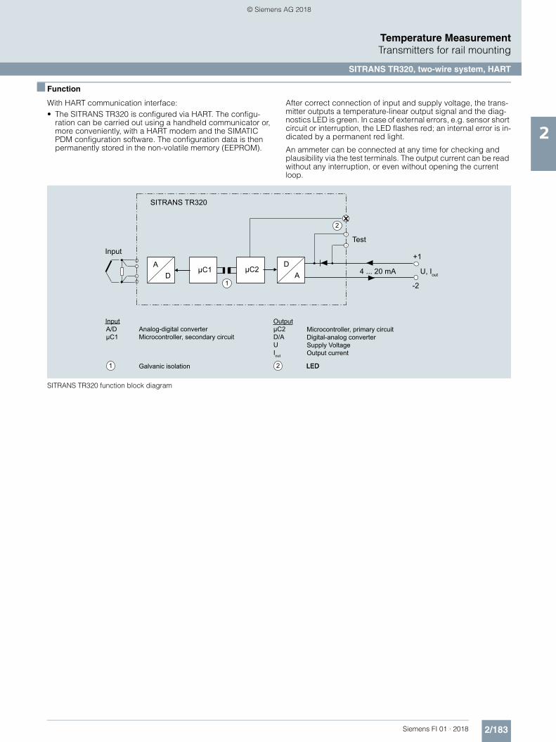
2/183Siemens FI 01 · 2018
Temperature MeasurementTransmitters for rail mounting
SITRANS TR320, two-wire system, HART
2
■ Function
With HART communication interface:• The SITRANS TR320 is configured via HART. The configu-
ration can be carried out using a handheld communicator or, more conveniently, with a HART modem and the SIMATIC PDM configuration software. The configuration data is then permanently stored in the non-volatile memory (EEPROM).
After correct connection of input and supply voltage, the trans-mitter outputs a temperature-linear output signal and the diag-nostics LED is green. In case of external errors, e.g. sensor short circuit or interruption, the LED flashes red; an internal error is in-dicated by a permanent red light.
An ammeter can be connected at any time for checking and plausibility via the test terminals. The output current can be read without any interruption, or even without opening the current loop.
SITRANS TR320 function block diagram
1
1
2
2
Input
Galvanic isolation LED
Microcontroller, primary circuitDigital-analog converterSupply VoltageOutput current
Analog-digital converterMicrocontroller, secondary circuit
OutputInput
+1
-2
μC1 μC2
Test
4 ... 20 mA U, Iout
SITRANS TR320
DA
AD
A/DμC1
μC2D/AUIout
LED
© Siemens AG 2018
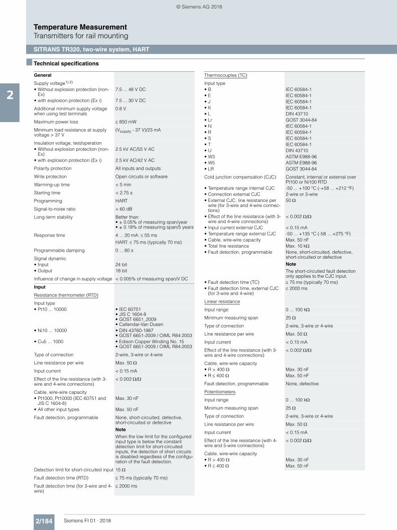
2/184 Siemens FI 01 · 2018
Temperature MeasurementTransmitters for rail mounting
SITRANS TR320, two-wire system, HART
2
■ Technical specifications
General
Supply voltage1) 2)
• Without explosion protection (non-Ex)
7.5 ... 48 V DC
• with explosion protection (Ex i) 7.5 ... 30 V DC
Additional minimum supply voltage when using test terminals
0.8 V
Maximum power loss 850 mW
Minimum load resistance at supply voltage > 37 V
(Vsupply - 37 V)/23 mA
Insulation voltage, test/operation• Without explosion protection (non-
Ex)2.5 kV AC/55 V AC
• with explosion protection (Ex i) 2.5 kV AC/42 V AC
Polarity protection All inputs and outputs
Write protection Open circuits or software
Warming-up time < 5 min
Starting time < 2.75 s
Programming HART
Signal-to-noise ratio > 60 dB
Long-term stability Better than:• ± 0.05% of measuring span/year• ± 0.18% of measuring span/5 years
Response time 4 ... 20 mA: 55 ms
HART: 75 ms (typically 70 ms)
Programmable damping 0 ... 60 s
Signal dynamic• Input 24 bit• Output 18 bit
Influence of change in supply voltage < 0.005% of measuring span/V DC
Input
Resistance thermometer (RTD)
Input type• Pt10 ... 10000 • IEC 60751
• JIS C 1604-8• GOST 6651_2009• Callendar-Van Dusen
• Ni10 ... 10000 • DIN 43760-1987• GOST 6651-2009 / OIML R84:2003
• Cu5 ... 1000 • Edison Copper Winding No. 15• GOST 6651-2009 / OIML R84:2003
Type of connection 2-wire, 3-wire or 4-wire
Line resistance per wire Max. 50
Input current < 0.15 mA
Effect of the line resistance (with 3-wire and 4-wire connections)
< 0.002 /
Cable, wire-wire capacity• Pt1000, Pt10000 (IEC 60751 and
JIS C 1604-8)Max. 30 nF
• All other input types Max. 50 nF
Fault detection, programmable None, short-circuited, defective, short-circuited or defective
Note
When the low limit for the configured input type is below the constant detection limit for short-circuited inputs, the detection of short circuits is disabled regardless of the configu-ration of the fault detection.
Detection limit for short-circuited input 15
Fault detection time (RTD) 75 ms (typically 70 ms)
Fault detection time (for 3-wire and 4-wire)
2000 ms
Thermocouples (TC)
Input type• B IEC 60584-1• E IEC 60584-1• J IEC 60584-1• K IEC 60584-1• L DIN 43710• Lr GOST 3044-84• N IEC 60584-1• R IEC 60584-1• S IEC 60584-1• T IEC 60584-1• U DIN 43710• W3 ASTM E988-96• W5 ASTM E988-96• LR GOST 3044-84
Cold junction compensation (CJC) Constant, internal or external over Pt100 or Ni100 RTD
• Temperature range internal CJC -50 ... +100 °C (-+58 ... +212 °F)• Connection external CJC 2-wire or 3-wire• External CJC, line resistance per
wire (for 3-wire and 4-wire connec-tions)
50
• Effect of the line resistance (with 3-wire and 4-wire connections)
< 0.002 /
• Input current external CJC < 0.15 mA• Temperature range external CJC -50 ... +135 °C (-58 ... +275 °F)• Cable, wire-wire capacity Max. 50 nF• Total line resistance Max. 10 k• Fault detection, programmable None, short-circuited, defective,
short-circuited or defective
Note
The short-circuited fault detection only applies to the CJC input.
• Fault detection time (TC) 75 ms (typically 70 ms)• Fault detection time, external CJC
(for 3-wire and 4-wire) 2000 ms
Linear resistance
Input range 0 ... 100 k
Minimum measuring span 25
Type of connection 2-wire, 3-wire or 4-wire
Line resistance per wire Max. 50
Input current < 0.15 mA
Effect of the line resistance (with 3-wire and 4-wire connections)
< 0.002 /
Cable, wire-wire capacity• R > 400 Max. 30 nF• R 400 Max. 50 nF
Fault detection, programmable None, defective
Potentiometers
Input range 0 ... 100 k
Minimum measuring span 25
Type of connection 2-wire, 3-wire or 4-wire
Line resistance per wire Max. 50
Input current < 0.15 mA
Effect of the line resistance (with 4-wire and 5-wire connections)
< 0.002 /
Cable, wire-wire capacity• R > 400 Max. 30 nF• R 400 Max. 50 nF
© Siemens AG 2018

2/185Siemens FI 01 · 2018
Temperature MeasurementTransmitters for rail mounting
SITRANS TR320, two-wire system, HART
2
1) Note that the minimum supply voltage must correspond to the value mea-sured at the terminals of the SITRANS TR320.All external voltage drops must be taken into consideration.
2) Protect the device from overvoltage with the help of a suitable power sup-ply or suitable overvoltage protection equipment.
3) Additional available certificates are listed on the Internet athttp://www.siemens.com/processinstrumentation/certificates
Fault detection, programmable None, short-circuited, defective, short-circuited or defective
Note
When the configured potentiometer size is below the constant detection limit for short-circuited inputs, the detection of short circuits is disabled regardless of the configuration of the fault detection.
Detection limit for short-circuited input 15
Fault detection time, wiper arm (no short-circuit detection)
75 ms (typically 70 ms)
Fault detection time, element 2000 ms
Fault detection time (for 4-wire and 5-wire)
2000 ms
Voltage input
Measuring range• Unipolar -100 ... 1700 mV• Bipolar -800 ... +800 mV
Minimum measuring span 2.5 mV
Input resistance 10 M
Cable, wire-wire capacity• Input range: -100 ... 1700 mV Max. 30 nF• Input range: -20 ... 100 mV Max. 50 nF
Fault detection, programmable None, defective
Fault detection time 75 ms (typically 70 ms)
Output and HART communication
Normal range, programmable 3.8 ... 20.5 mA/20.5 ... 3.8 mA
Extended range (output limits), pro-grammable
3.5 ... 23 mA/23 ... 3.5 mA
Programmable input/output limits• Fault current Enable/disable• Fault current setting 3.5 ... 23 mA
Update time 10 ms
Load (with current output) (VSupply - 7.5)/0.023
Load stability < 0.01% of meas. span/100 (measuring span = currently selected range)
Input fault detection, programmable(detection of input short circuits is ignored with TC and voltage inputs)
3.5 ... 23 mA
NAMUR NE43 Upscale > 21 mA
NAMUR NE43 Downscale < 3.6 mA
HART protocol versions HART 7
Measuring accuracy
Input accuracy See "Input accuracy" table
Output accuracy See "Output accuracy" table
Rated conditions
Ambient temperature (operation)• Standard -50 ... +85 °C (-58 ... +185 °F)• SIL -40 ... +80 °C (-40 ... +176 °F)
Storage temperature -50 ... +85 °C (-58 ... +185 °F)
Calibration temperature 24 °C ±1.0 °C (75.2 °F ±1.8 °F)
Relative humidity < 99% (no condensation)
Degree of protection• Enclosure of the transmitter IP20• Terminals IP20
Design
Weight 122 g (0.27 lb)
Maximum cable cross-section 2.5 mm² (AWG 13)
Tightening torque for clamping screws
0.5 ... 0.6 Nm
Vibrations IEC 60068-2-6• 2 ... 25 Hz ± 1.6 mm (0.07 inch)• 25 ... 100 Hz ± 4 g
Certificates and approvals
Explosion protection ATEX/IECEx and others
Certificates 3) DEKRA 17ATEX0116 X
IECEx DEK 17.0054X
A5E43700604A-2018X
"Intrinsic safety ia/ib" type of protec-tion
For use in Zone 0, 1, 2, 20, 21, 22
• ATEX II 1 G Ex ia IIC T6 ... T4 GaII 2(1) G Ex ib [ia Ga] IIC T6 ... T4 GbII 1 D Ex ia IIIC DaI M1 Ex ia I Ma
• IECEx and others Ex ia IIC T6 ... T4 GaEx ib [ia Ga] IIC T6 ... T4 GbEx ia IIIC DaEx ia I Ma
"Intrinsic safety ic" type of protection For use in Zones 2 and 22• ATEX II 2 G Ex ic IIC T6…T4 Gc
II 2 D Ex ic IIIC Dc• IECEx and others Ex ic IIC T6 ... T4 Gc
Ex ic IIIC Dc
"Non-sparking/increased safety nA/ec" type of protection
For use in Zones 2 and 22
• ATEX II 2 G Ex nA IIC T6…T4 GcII 2 G Ex ec IIC T6…T4 Gc
• IECEx and others Ex nA IIC T6 ... T4 GcEx ec IIC T6 ... T4 Gc
Explosion protection CSA /FM for Canada and USA
Certificates CSA 1861385FM18CA0024FM18US0046
"Intrinsic safety ia" type of protection IS, CL I, Div 1, GP ABCD, T6 ... T4
Ex ia IIC T6 … T4 GaAEx ia IIC T6 … T4 Ga or:
Ex ib [ia Ga] IIC T6…T4 GbAEx ib [ia Ga] IIC T6…T4 Gb
"Non incendive field wiring NIFW" type of protection
NIFW, CL I, Div 2, GP ABCD T6 ... T4
"Non incendive NI" type of protection NI, CL I, Div 2, GP ABCD T6...T4Ex nA IIC T6 ... T4 GcAEx nA IIC T6 ... T4 Gc
© Siemens AG 2018

2/186 Siemens FI 01 · 2018
Temperature MeasurementTransmitters for rail mounting
SITRANS TR320, two-wire system, HART
2
Measuring ranges/Minimum measuring span
RTD
TC
Input accuracy
Basic values
Input type Standard Measuring range in °C (°F) 0 in °C-1 (°F-1) Minimum measuring span in °C (°F)
Pt10 ... 10000 IEC 60751 -200 ... +850 (-328 ... +1562) 0.003851 (0.002139) 10 (50)
JIS C 1604-8 -200 ... +649 (-328 ... +1200) 0.003916 (0.002176) 10 (50)
GOST 6651_2009 -200 ... +850 (-328 ... +1562) 0.003910 (0.002172) 10 (50)
Callendar-Van Dusen -200 ... +850 (-328 ... +1562) - 10 (50)
Ni10 ... 10000 DIN 43760-1987 -60 ... +250 (-76 ... +482) 0.006180 (0.003433) 10 (50)
GOST 6651-2009 / OIML R84:2003
-60 ... +180 (-76 ... +356) 0.006170 (0.003428) 10 (50)
Cu5 ... 1000 Edison Copper Winding No. 15
-200 ... +260 (-328 ... +500) 0.004270 (0.002372) 100 (212)
GOST 6651-2009 / OIML R84:2003
-180 ... +200 (-292 ... +392) 0.004280 (0.002378) 100 (212)
GOST 6651-94 -50 ... +200 (-58 ... +392) 0.004260 (0.002367) 100 (212)
Input type Standard Measuring range in °C (°F) Minimum measuring span in °C (°F)
B IEC 60584-1 0 (85) ... 1 820 (32 (185) ... 3 308) 100 (212)
E IEC 60584-1 -200 ... +1 000 (-392 ... +1 832) 50 (122)
J IEC 60584-1 -100 ... +1200 (-212 ... +2192) 50 (122)
K IEC 60584-1 -180 ... +1372 (-356 ... +2502) 50 (122)
L DIN 43710 -200 ... +900 (-392 ... +1652) 50 (122)
Lr GOST 3044-84 -200 ... +800 (-392 ... +1472) 50 (122)
N IEC 60584-1 -180 ... +1300 (-356 ... +2372) 50 (122)
R IEC 60584-1 -50 ... +1760 (-122 ... +3200) 100 (212)
S IEC 60584-1 -50 ... +1760 (-122 ... +3200) 100 (212)
T IEC 60584-1 -200 ... +400 (-392 ... +752) 50 (122)
U DIN 43710 -200 ... +600 (-392 ... +1112) 50 (122)
W3 ASTM E988-96 0 ... 2300 (32 ... 4172) 100 (212)
W5 ASTM E988-96 0 ... 2300 (32 ... 4172) 100 (212)
LR GOST 3044-84 -200 ... +800 (-392 ... +1472) 50 (122)
Input type Basic accuracy Temperature coefficient1)
RTD
Pt10 ±0.8 °C (1.44 °F) ±0.020 °C/°C (°F/°F)
Pt20 ±0.4 °C (0.72 °F) ±0.010 °C/°C (°F/°F)
Pt50 ±0.16 °C (0.288 °F) ±0.004 °C/°C (°F/°F)
Pt100 ±0.04 °C (0.072 °F) ±0.002 °C/°C (°F/°F)
Pt200 ±0.08 °C (0.144 °F) ±0.002 °C/°C (°F/°F)
Pt500 Tmax. < 180 °C (356 °F) = ±0.08 °C (0.144 °F)
Tmax. < 180 °C (356 °F) = ±0.16 °C (0.288 °F)
±0.002 °C/°C (°F/°F)
Pt1000 ±0.08 °C (0.144 °F) ±0.002 °C/°C (°F/°F)
Pt2000 Tmax. < 300 °C (572 °F) = ±0.08 °C (0.144 °F)
Tmax. < 300 °C (572 °F) = ±0.4 °C (0.72 °F)
±0.002 °C/°C (°F/°F)
Pt10000 ±0.16 °C (0.288 °F) ±0.002 °C/°C (°F/°F)
Pt x Largest tolerance of neighboring points Largest temperature coefficient of neighboring points
Ni10 ±1.6 °C (2.88 °F) ±0.020 °C/°C (°F/°F)
Ni20 ±0.8 °C (1.44 °F) ±0.010 °C/°C (°F/°F)
Ni50 ±0.32 °C (0.576 °F) ±0.004 °C/°C (°F/°F)
Ni100 ±0.16 °C (0.288 °F) ±0.002 °C/°C (°F/°F)
Ni120 ±0.16 °C (0.288 °F) ±0.002 °C/°C (°F/°F)
Ni200 ±0.16 °C (0.288 °F) ±0.002 °C/°C (°F/°F)
Ni500 ±0.16 °C (0.288 °F) ±0.002 °C/°C (°F/°F)
Ni1000 ±0.16 °C (0.288 °F) ±0.002 °C/°C (°F/°F)
Ni2000 ±0.16 °C (0.288 °F) ±0.002 °C/°C (°F/°F)
© Siemens AG 2018

2/187Siemens FI 01 · 2018
Temperature MeasurementTransmitters for rail mounting
SITRANS TR320, two-wire system, HART
2
1) Temperature coefficients correspond to the specified values or 0.002% of the input span, depending on which value is greater.
2) Accuracy of the specification range > 400 °C (752 °F)3) Accuracy of the specification range > 160 °C (320 °F) < 400 °C (752 °F)4) Accuracy of the specification range > 85 °C (185 °F) < 160 °C (320 °F)5) Accuracy of the specification range > 85 °C (185 °F)
Output accuracy
Ni10000 ±0.32 °C (0.576 °F) ±0.002 °C/°C (°F/°F)
Ni x Largest tolerance of neighboring points Largest temperature coefficient of neighboring points
Cu5 ±1.6 °C (2.88 °F) ±0.040 °C/°C (°F/°F)
Cu10 ±0.8 °C (1.44 °F) ±0.020 °C/°C (°F/°F)
Cu20 ±0.4 °C (0.72 °F) ±0.010 °C/°C (°F/°F)
Cu50 ±0.16 °C (0.288 °F) ±0.004 °C/°C (°F/°F)
Cu100 ±0.08 °C (0.144 °F) ±0.002 °C/°C (°F/°F)
Cu200 ±0.08 °C (0.144 °F) ±0.002 °C/°C (°F/°F)
Cu500 ±0.16 °C (0.288 °F) ±0.002 °C/°C (°F/°F)
Cu1000 ±0.08 °C (0.144 °F) ±0.002 °C/°C (°F/°F)
Cu x Largest tolerance of neighboring points Largest temperature coefficient of neighboring points
Linear resistance
0 ... 400 ±40 m ±2 m/°C (1.11 m/°F)
0 ... 100 k ±4 ±0.2 /°C (0.11 /°F)
Potentiometers
0 ... 100% < 0.05% < ± 0.005%
Voltage input
mV: -20 ... 100 mV ±5 V ±0.2 V/°C (0.11 V/°F)
mV: -100 ... 1700 mV ±0.1 mV ±36 V/°C (20 V/°F)
mV: ± 800 mV ±0.1 mV ±32 V/°C (17.8 V/°F)
TC
E ±0.2 °C (0.36 °F) ±0.025 °C/°C (°F/°F)
J ±0.25 °C (0.45 °F) ±0.025 °C/°C (°F/°F)
K ±0.25 °C (0.45 °F) ±0.025 °C/°C (°F/°F)
L ±0.35 °C (0.63 °F) ±0.025 °C/°C (°F/°F)
N ±0.4 °C (0.72 °F) ±0.025 °C/°C (°F/°F)
T ±0.25 °C (0.45 °F) ±0.025 °C/°C (°F/°F)
U < 0 °C (32 °F) ±0.8 °C (1.44 °F)
0 °C (32 °F) ±0.4 °C (0.72 °F)
±0.025 °C/°C (°F/°F)
Lr ±0.2 °C (0.36 °F) ±0.1 °C/°C (°F/°F)
R < 200 °C (392 °F) ±0.5 °C (0.9 °F)
200 °C (392 °F) ±1 °C (1.8 °F)
±0.1 °C/°C (°F/°F)
S < 200 °C (392 °F) ±0.5 °C (0.9 °F)
200 °C (392 °F) ±1 °C (1.8 °F)
±0.1 °C/°C (°F/°F)
W3 ±0.6 °C (1.08 °F) ±0.1 °C/°C (°F/°F)
W5 ±0.4 °C (0.72 °F) ±0.1 °C/°C (°F/°F)
B2) ±1 °C (1.8 °F) ±0.1 °C/°C (°F/°F)
B3) ±3 °C (5.4 °F) ±0.1 °C/°C (°F/°F)
B4) ±8 °C (14.4 °F) ±0.8 °C/°C (°F/°F)
B5) Not specified Not specified
CJC (internal) ±0.5 °C (0.9 °F) Included in basic accuracy
CJC (external) ±0.08 °C (0.144 °F) ±0.002 °C/°C (°F/°F)
Input type Basic accuracy Temperature coefficient1)
Output type Basic accuracy Temperature coefficient
Analog output ±1.6 A (0.01% of the full output span)
±0.48 A/K ( ±0.003% of the full output span/K)
© Siemens AG 2018

2/188 Siemens FI 01 · 2018
Temperature MeasurementTransmitters for rail mounting
SITRANS TR320, two-wire system, HART
2
■ Selection and ordering data
Article No.
Temperature transmitterSITRANS TR320 with 1 input
7NG032
7 - 77777 - 0777
Click on the Article no. for the online configuration in the PIA Life Cycle Portal.
Communication
With HART 0
Primary value output
Input 1 0
Input 1, type
RTD• Pt100 (IEC), 3-wire B• Pt100 (IEC), 4-wire C• Pt1000 (IEC), 3-wire D• Pt1000 (IEC), 4-wire E
TC• Type B F• Type E G• Type J H• Type K J• Type L K• Type N L• Type R N• Type S P• Type T Q
Potentiometer, 4-wire R
Input 1, type customer-specific
Define customer-specific input configurations with V options
Y
Input 2, type
Without input 2 A
CJC configuration for TC
Without CJC 0
Internal CJC 1
External CJC Pt100 (IEC), 2-wire, define line resis-tance value in option Y53
2
External CJC Pt100 (IEC), 3-wire 3
External CJC Ni100 (DIN), 2-wire, define line resis-tance value in option Y53
5
External CJC Ni100 (DIN), 3-wire 6
Materials not in contact with media
None 0
Type of protection
General safety (non-Ex); CE, RCM, FM, CSA, KCC A
Ex i, Ex nA (ec) (Zone)/IS, NIFW, NI (Division); ATEX, IECEx, CSA, FM, NEPSI
N
Electrical connection/cable entry
None A
Local HMI
Without display 0
Options Order code
Add "-Z" to article no. and specify order code.
Certificates for functional safety
Functional safety SIL2/3 (IEC 61508) C20
Special features of enclosure/packaging
Without labeling of the measuring range on the TAG label D41
Input 1: TC
Type C W5 V01
Type D W3 V02
Type U V03
Type Lr V04
Input 1: RTD
Pt x (IEC), 3-wire, define RTD factor x in option Y21 V61
Pt x (IEC), 4-wire, define RTD factor x in option Y21 V62
Pt x (JIS C1604-81), 3-wire, define RTD factor x in option Y21
V64
Pt x (JIS C1604-81), 4-wire, define RTD factor x in option Y21
V65
Pt x (GOST 6651-2009), 3-wire, define RTD factor x in option Y21
V67
Pt x (GOST 6651-2009), 4-wire, define RTD factor x in option Y21
V68
Ni x (DIN 43760-87), 3-wire, define RTD factor x in option Y21
V70
Ni x (DIN 43760-87), 4-wire, define RTD factor x in option Y21
V71
Ni x (GOST 6651-2009), 3-wire, define RTD factor x in option Y21
V73
Ni x (GOST 6651-2009), 4-wire, define RTD factor x in option Y21
V74
Cu x (ECW-15), 3-wire, define RTD factor x in option Y21 V76
Cu x (ECW-15), 4-wire, define RTD factor x in option Y21 V77
Cu x (GOST 6651-94), 3-wire, define RTD factor x in option Y21
V79
Cu x (GOST 6651-94), 4-wire, define RTD factor x in option Y21
V80
Cu x (GOST 6651-2009), 3-wire, define RTD factor x in option Y21
V82
Cu x (GOST 6651-2009), 4-wire, define RTD factor x in option Y21
V83
© Siemens AG 2018

2/189Siemens FI 01 · 2018
Temperature MeasurementTransmitters for rail mounting
SITRANS TR320, two-wire system, HART
2
■ Selection and ordering data
Ordering example
7NG0320-0BA00-0AA0-Z Y01
Y01: -10 ... +100 °C
Factory setting• Pt100 (IEC 751); 3-wire connection• Measuring range: 0 ... 100 °C (32 ... 212 °F)• Fault current
- Input circuit wire break: 22.8 mA- Input circuit short circuit: 22.4 mA- Input monitoring wire break and short-circuit
• No trimming of input and output (offset)• Damping 0.0 s
■ Dimensional drawings
SITRANS TR320, dimensions in mm (inch)
Customer-specific device settings Order code
Add "-Z" to article no., specify order code and plain text or drop-down list selection.
Measuring range setting temperature input: Start of scale value (max. 5 characters), full scale value (max. 5 characters), unit (°C, °F, °Ra, K)
Y01
Plant designation (TAG, device parameters, max. 32 characters)
Y15
Measuring point message (device message and device parameters, max. 32 characters)
Y16
Plant designation short (TAG, device parameters, max. 8 characters) on front plate, only for SITRANS TR320/SITRANS TR420
Y19
Input 1: RTD factor; e.g. factor "200" = Pt200 Y21
Accessories Article No.
Further accessories for assembly, connection and transmitter configu-ration, see page 2/237.
HART modem
With USB interface
7MF4997-1DB
SIMATIC PDM parameterization software
See Catalog FI 01 section 8
22.5
(0.8
9)
(4.4
9)
(3.9)99
114
© Siemens AG 2018

2/190 Siemens FI 01 · 2018
Temperature MeasurementTransmitters for rail mounting
SITRANS TR320, two-wire system, HART
2
■ Circuit diagrams
Connections
SITRANS TR320, connector assignment
Output and test connection
SITRANS TR320, output connection assignment
Input connection
SITRANS TR320, input connection assignment
1 (+) and 2 (-)
3 (+) and 4 (-)5, 6, 7 and 8
Test terminals for measurement ofthe output current with an amperemeter
Output terminals Input terminals
+ -+ -
Test terminals Output terminals
1 2 3 41 2 3 4
UA
2-wire, 3-wire or 4-wire RTDor linear resistance
TC (internal CJC orexternal 2-wire or 3-wire CJC)
Voltage input(unipolar or bipolar)
3 4I1
+
3
CJC
+
5 6 7 85 6 7 8 5 6 7 8
© Siemens AG 2018

2/191Siemens FI 01 · 2018
Temperature MeasurementTransmitters for rail mounting
SITRANS TR420, two-wire system, HART
2
■ Overview
• 2-wire temperature transmitter with HART communication interface
• Device for rail mounting• Universal input for virtually any type of temperature sensor• Connection of two independent input circuits for redundant
operation (high input availability)• Input drift detection• Configurable over HART
■ Benefits
• Compact design• Connection of two independent input circuits for redundant
operation (high input availability)• Electrical isolation• Test terminals for ammeter• Diagnostics LED (green/red)• Input monitoring
Wire break and short-circuit• Self-monitoring• Configuration status stored in EEPROM• Expanded diagnostic functions, such as slave pointer,
operating hours counter, etc.• Special characteristic• Electromagnetic compatibility according to DIN EN 61326
and NE21• SIL2/3 (with order note C20)
■ Application
SITRANS TR420 transmitters with two inputs can be used in all sectors. Their compact design enables simple mounting on standard DIN rails on-site in protective boxes or in control cabi-nets. The following sensors/signal sources can be connected over their universal input module:• 2 resistance thermometers (2-wire, 3-wire, 4-wire connection)• 2 thermocouples• 2 linear resistors, potentiometer and DC voltage sources
The output signal is a load-independent direct current from 4 to 20 mA in accordance with the input characteristic, superim-posed by the digital HART signal.
The dual input mode also supports drift detection of the inputs, whereby maintenance intervals can be more easily planned.
Transmitters of the "intrinsically safe or Zone 2 increased safety" type of protection can be installed in hazardous areas. The de-vice meets the requirements of the EU Directive 2014/34/EU (ATEX), the FM and CSA regulations as well as other national ap-provals.
© Siemens AG 2018
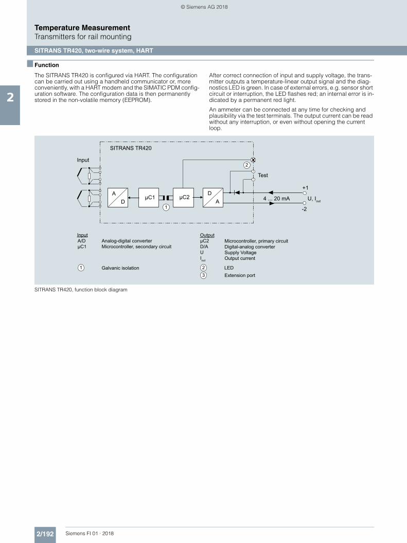
2/192 Siemens FI 01 · 2018
Temperature MeasurementTransmitters for rail mounting
SITRANS TR420, two-wire system, HART
2
■ Function
The SITRANS TR420 is configured via HART. The configuration can be carried out using a handheld communicator or, more conveniently, with a HART modem and the SIMATIC PDM config-uration software. The configuration data is then permanently stored in the non-volatile memory (EEPROM).
After correct connection of input and supply voltage, the trans-mitter outputs a temperature-linear output signal and the diag-nostics LED is green. In case of external errors, e.g. sensor short circuit or interruption, the LED flashes red; an internal error is in-dicated by a permanent red light.
An ammeter can be connected at any time for checking and plausibility via the test terminals. The output current can be read without any interruption, or even without opening the current loop.
SITRANS TR420, function block diagram
1
1
23
2Input
Galvanic isolation
OutputMicrocontroller, primary circuitDigital-analog converterSupply VoltageOutput current
Analog-digital converterMicrocontroller, secondary circuit
Input
Extension port
+1
-2
μC1 μC2
Test
4 ... 20 mA U, Iout
SITRANS TR420
DA
AD
A/DμC1
μC2D/AUIout
LED
© Siemens AG 2018

2/193Siemens FI 01 · 2018
Temperature MeasurementTransmitters for rail mounting
SITRANS TR420, two-wire system, HART
2
■ Technical specifications
General
Supply voltage1) 2)
• Without explosion protection (non-Ex)
7.5 ... 48 V DC
• with explosion protection (Ex i) 7.5 ... 30 V DC
Additional minimum supply voltage when using test terminals
0.8 V
Maximum power loss 850 mW
Minimum load resistance at supply voltage > 37 V
(Vsupply - 37 V)/23 mA
Insulation voltage, test/operation• Without explosion protection (non-
Ex)2.5 kV AC/55 V AC
• with explosion protection (Ex i) 2.5 kV AC/42 V AC
Polarity protection All inputs and outputs
Write protection Open circuits or software
Warming-up time < 5 min
Starting time < 2.75 s
Programming SIPROM T and HART
Signal-to-noise ratio > 60 dB
Long-term stability Better than:• ± 0.05% of measuring span/year• ± 0.18% of measuring span/5 years
Response time 75 ms (typically 70 ms)
Programmable damping 0 ... 60 s
Signal dynamic• Input 24 bit• Output 18 bit
Influence of change in supply voltage < 0.005% of measuring span/V DC
Input
Resistance thermometer (RTD)
Input type• Pt10 ... 10000 • IEC 60751
• JIS C 1604-8• GOST 6651_2009• Callendar-Van Dusen
• Ni10 ... 10000 • DIN 43760-1987• GOST 6651-2009 / OIML R84:2003
• Cu5 ... 1000 • Edison Copper Winding No. 15• GOST 6651-2009 / OIML R84:2003
Type of connection 2-wire, 3-wire or 4-wire
Line resistance per wire Max. 50
Input current < 0.15 mA
Effect of the line resistance(with 3-wire and 4-wire connections)
< 0.002 /
Cable, wire-wire capacity• Pt1000, Pt10000 (IEC 60751 and
JIS C 1604-8)Max. 30 nF
• All other input types Max. 50 nF
Fault detection, programmable None, short-circuited, defective, short-circuited or defective
Note
When the low limit for the configured input type is below the constant detection limit for short-circuited inputs, the detection of short circuits is disabled regardless of the configu-ration of the fault detection.
Detection limit for short-circuited input 15
Fault detection time (RTD) 75 ms (typically 70 ms)
Fault detection time (for 3-wire and 4-wire)
2000 ms
Thermocouples (TC)
Input type• B IEC 60584-1• E IEC 60584-1• J IEC 60584-1• K IEC 60584-1• L DIN 43710• Lr GOST 3044-84• N IEC 60584-1• R IEC 60584-1• S IEC 60584-1• T IEC 60584-1• U DIN 43710• W3 ASTM E988-96• W5 ASTM E988-96• LR GOST 3044-84
Cold junction compensation (CJC) Constant, internal or external over Pt100 or Ni100 RTD
• Temperature range internal CJC -50 ... +100 °C (-+58 ... +212 °F)• Connection external CJC 2-wire, 3-wire or 4-wire• External CJC, line resistance per
wire (for 3-wire and 4-wire connec-tions)
50
• Effect of the line resistance (with 3-wire and 4-wire connections)
< 0.002 /
• Input current external CJC < 0.15 mA• Temperature range external CJC -50 ... +135 °C (-58 ... +275 °F)• Cable, wire-wire capacity Max. 50 nF• Total line resistance Max. 10 k• Fault detection, programmable None, short-circuited, defective,
short-circuited or defective
Note
The short-circuited fault detection only applies to the CJC input.
• Fault detection time (TC) 75 ms (typically 70 ms)• Fault detection time, external CJC
(for 3-wire and 4-wire) 2000 ms
Linear resistance
Input range 0 ... 100 k
Minimum measuring span 25
Type of connection 2-wire, 3-wire or 4-wire
Line resistance per wire Max. 50
Input current < 0.15 mA
Effect of the line resistance (with 3-wire and 4-wire connections)
< 0.002 /
Cable, wire-wire capacity• R > 400 Max. 30 nF• R 400 Max. 50 nF
Fault detection, programmable None, defective
Potentiometers
Input range 0 ... 100 k
Minimum measuring span 25
Type of connection 2-wire, 3-wire or 4-wire
Line resistance per wire Max. 50
Input current < 0.15 mA
Effect of the line resistance (with 4-wire and 5-wire connections)
< 0.002 /
Cable, wire-wire capacity• R > 400 Max. 30 nF• R 400 Max. 50 nF
© Siemens AG 2018

2/194 Siemens FI 01 · 2018
Temperature MeasurementTransmitters for rail mounting
SITRANS TR420, two-wire system, HART
2
1) Note that the minimum supply voltage must correspond to the value mea-sured at the terminals of the SITRANS TR420.All external voltage drops must be taken into consideration.
2) Protect the device from overvoltage with the help of a suitable power sup-ply or suitable overvoltage protection equipment.
3) Additional available certificates are listed on the Internet athttp://www.siemens.com/processinstrumentation/certificates
Fault detection, programmable None, short-circuited, defective, short-circuited or defective
Note
When the configured potentiometer size is below the constant detection limit for short-circuited inputs, the detection of short circuits is disabled regardless of the configuration of the fault detection.
Detection limit for short-circuited input 15
Fault detection time, wiper arm (no short-circuit detection)
75 ms (typically 70 ms)
Fault detection time, element 2000 ms
Fault detection time (for 4-wire and 5-wire)
2000 ms
Voltage input
Measuring range• Unipolar -100 ... 1700 mV• Bipolar -800 ... +800 mV
Minimum measuring span 2.5 mV
Input resistance 10 M
Cable, wire-wire capacity• Input range: -100 ... 1700 mV Max. 30 nF• Input range: -20 ... 100 mV Max. 50 nF
Fault detection, programmable None, defective
Fault detection time 75 ms (typically 70 ms)
Output and HART communication
Normal range, programmable 3.8 ... 20.5 mA/20.5 ... 3.8 mA
Extended range (output limits), pro-grammable
3.5 ... 23 mA/23 ... 3.5 mA
Programmable input/output limits• Fault current Enable/disable• Fault current setting 3.5 ... 23 mA
Update time 10 ms
Load (with current output) (VSupply - 7.5)/0.023
Load stability < 0.01% of meas. span/100 (measuring span = currently selected range)
Input fault detection, programmable(detection of input short circuits is ignored with TC and voltage inputs)
3.5 ... 23 mA
NAMUR NE43 Upscale > 21 mA
NAMUR NE43 Downscale < 3.6 mA
HART protocol versions HART 7
Measuring accuracy
Input accuracy See "Input accuracy" table
Output accuracy See "Output accuracy" table
Rated conditions
Ambient temperature (operation)• Standard -50 ... +85 °C (-58 ... +185 °F)• SIL -40 ... +80 °C (-40 ... +176 °F)
Storage temperature -50 ... +85 °C (-58 ... +185 °F)
Calibration temperature 24 °C ±1.0 °C (75.2 °F ±1.8 °F)
Relative humidity < 99% (no condensation)
Degree of protection• Enclosure of the transmitter IP20• Terminals IP20
Design
Weight 122 g (0.27 lb)
Maximum cable cross-section 2.5 mm² (AWG 13)
Tightening torque for clamping screws
0.5 ... 0.6 Nm
Vibrations IEC 60068-2-6• 2 ... 25 Hz ± 1.6 mm (0.07 inch)• 25 ... 100 Hz ± 4 g
Certificates and approvals
Explosion protection ATEX/IECEx and others
Certificates 3) DEKRA 17ATEX0116 X
IECEx DEK 17.0054X
A5E43700604A-2018X
"Intrinsic safety ia/ib" type of protec-tion
For use in Zone 0, 1, 2, 20, 21, 22
• ATEX II 1 G Ex ia IIC T6 ... T4 GaII 2(1) G Ex ib [ia Ga] IIC T6 ... T4 GbII 1 D Ex ia IIIC DaI M1 Ex ia I Ma
• IECEx and others Ex ia IIC T6 ... T4 GaEx ib [ia Ga] IIC T6 ... T4 GbEx ia IIIC DaEx ia I Ma
"Intrinsic safety ic" type of protection For use in Zones 2 and 22• ATEX II 2 G Ex ic IIC T6…T4 Gc
II 2 D Ex ic IIIC Dc• IECEx and others Ex ic IIC T6 ... T4 Gc
Ex ic IIIC Dc
"Non-sparking/increased safety nA/ec" type of protection
For use in Zones 2 and 22
• ATEX II 2 G Ex nA IIC T6…T4 GcII 2 G Ex ec IIC T6…T4 Gc
• IECEx and others Ex nA IIC T6 ... T4 GcEx ec IIC T6 ... T4 Gc
Explosion protection CSA /FM for Canada and USA
Certificates CSA 1861385FM18CA0024FM18US0046
"Intrinsic safety ia" type of protection IS, CL I, Div 1, GP ABCD, T6 ... T4
Ex ia IIC T6 … T4 GaAEx ia IIC T6 … T4 Ga or:
Ex ib [ia Ga] IIC T6…T4 GbAEx ib [ia Ga] IIC T6…T4 Gb
"Non incendive field wiring NIFW" type of protection
NIFW, CL I, Div 2, GP ABCD T6 ... T4
"Non incendive NI" type of protection NI, CL I, Div 2, GP ABCD T6...T4Ex nA IIC T6 ... T4 GcAEx nA IIC T6 ... T4 Gc
© Siemens AG 2018

2/195Siemens FI 01 · 2018
Temperature MeasurementTransmitters for rail mounting
SITRANS TR420, two-wire system, HART
2
Measuring ranges/Minimum measuring span
RTD
TC
Input accuracy
Basic values
Input type Standard Measuring range in °C (°F) 0 in °C-1 (°F-1) Minimum measuring span in °C (°F)
Pt10 ... 10000 IEC 60751 -200 ... +850 (-328 ... +1562) 0.003851 (0.002139) 10 (50)
JIS C 1604-8 -200 ... +649 (-328 ... +1200) 0.003916 (0.002176) 10 (50)
GOST 6651_2009 -200 ... +850 (-328 ... +1562) 0.003910 (0.002172) 10 (50)
Callendar-Van Dusen -200 ... +850 (-328 ... +1562) - 10 (50)
Ni10 ... 10000 DIN 43760-1987 -60 ... +250 (-76 ... +482) 0.006180 (0.003433) 10 (50)
GOST 6651-2009 / OIML R84:2003
-60 ... +180 (-76 ... +356) 0.006170 (0.003428) 10 (50)
Cu5 ... 1000 Edison Copper Winding No. 15
-200 ... +260 (-328 ... +500) 0.004270 (0.002372) 100 (212)
GOST 6651-2009 / OIML R84:2003
-180 ... +200 (-292 ... +392) 0.004280 (0.002378) 100 (212)
GOST 6651-94 -50 ... +200 (-58 ... +392) 0.004260 (0.002367) 100 (212)
Input type Standard Measuring range in °C (°F) Minimum measuring span in °C (°F)
B IEC 60584-1 0 (85) ... 1 820 (32 (185) ... 3 308) 100 (212)
E IEC 60584-1 -200 ... +1 000 (-392 ... +1 832) 50 (122)
J IEC 60584-1 -100 ... +1200 (-212 ... +2192) 50 (122)
K IEC 60584-1 -180 ... +1372 (-356 ... +2502) 50 (122)
L DIN 43710 -200 ... +900 (-392 ... +1652) 50 (122)
Lr GOST 3044-84 -200 ... +800 (-392 ... +1472) 50 (122)
N IEC 60584-1 -180 ... +1300 (-356 ... +2372) 50 (122)
R IEC 60584-1 -50 ... +1760 (-122 ... +3200) 100 (212)
S IEC 60584-1 -50 ... +1760 (-122 ... +3200) 100 (212)
T IEC 60584-1 -200 ... +400 (-392 ... +752) 50 (122)
U DIN 43710 -200 ... +600 (-392 ... +1112) 50 (122)
W3 ASTM E988-96 0 ... 2300 (32 ... 4172) 100 (212)
W5 ASTM E988-96 0 ... 2300 (32 ... 4172) 100 (212)
LR GOST 3044-84 -200 ... +800 (-392 ... +1472) 50 (122)
Input type Basic accuracy Temperature coefficient1)
RTD
Pt10 ±0.8 °C (1.44 °F) ±0.020 °C/°C (°F/°F)
Pt20 ±0.4 °C (0.72 °F) ±0.010 °C/°C (°F/°F)
Pt50 ±0.16 °C (0.288 °F) ±0.004 °C/°C (°F/°F)
Pt100 ±0.04 °C (0.072 °F) ±0.002 °C/°C (°F/°F)
Pt200 ±0.08 °C (0.144 °F) ±0.002 °C/°C (°F/°F)
Pt500 Tmax. < 180 °C (356 °F) = ±0.08 °C (0.144 °F)
Tmax. < 180 °C (356 °F) = ±0.16 °C (0.288 °F)
±0.002 °C/°C (°F/°F)
Pt1000 ±0.08 °C (0.144 °F) ±0.002 °C/°C (°F/°F)
Pt2000 Tmax. < 300 °C (572 °F) = ±0.08 °C (0.144 °F)
Tmax. < 300 °C (572 °F) = ±0.4 °C (0.72 °F)
±0.002 °C/°C (°F/°F)
Pt10000 ±0.16 °C (0.288 °F) ±0.002 °C/°C (°F/°F)
Pt x Largest tolerance of neighboring points Largest temperature coefficient of neighboring points
Ni10 ±1.6 °C (2.88 °F) ±0.020 °C/°C (°F/°F)
Ni20 ±0.8 °C (1.44 °F) ±0.010 °C/°C (°F/°F)
Ni50 ±0.32 °C (0.576 °F) ±0.004 °C/°C (°F/°F)
Ni100 ±0.16 °C (0.288 °F) ±0.002 °C/°C (°F/°F)
Ni120 ±0.16 °C (0.288 °F) ±0.002 °C/°C (°F/°F)
Ni200 ±0.16 °C (0.288 °F) ±0.002 °C/°C (°F/°F)
Ni500 ±0.16 °C (0.288 °F) ±0.002 °C/°C (°F/°F)
Ni1000 ±0.16 °C (0.288 °F) ±0.002 °C/°C (°F/°F)
Ni2000 ±0.16 °C (0.288 °F) ±0.002 °C/°C (°F/°F)
© Siemens AG 2018

2/196 Siemens FI 01 · 2018
Temperature MeasurementTransmitters for rail mounting
SITRANS TR420, two-wire system, HART
2
1) Temperature coefficients correspond to the specified values or 0.002% of the input span, depending on which value is greater.
2) 2) Accuracy of the specification range > 400 °C (752 °F)3) 3) Accuracy of the specification range > 160 °C (320 °F) < 400 °C (752 °F)4) 4) Accuracy of the specification range > 85 °C (185 °F) < 160 °C (320 °F)5) 5) Accuracy of the specification range > 85 °C (185 °F)
Output accuracy
Ni10000 ±0.32 °C (0.576 °F) ±0.002 °C/°C (°F/°F)
Ni x Largest tolerance of neighboring points Largest temperature coefficient of neighboring points
Cu5 ±1.6 °C (2.88 °F) ±0.040 °C/°C (°F/°F)
Cu10 ±0.8 °C (1.44 °F) ±0.020 °C/°C (°F/°F)
Cu20 ±0.4 °C (0.72 °F) ±0.010 °C/°C (°F/°F)
Cu50 ±0.16 °C (0.288 °F) ±0.004 °C/°C (°F/°F)
Cu100 ±0.08 °C (0.144 °F) ±0.002 °C/°C (°F/°F)
Cu200 ±0.08 °C (0.144 °F) ±0.002 °C/°C (°F/°F)
Cu500 ±0.16 °C (0.288 °F) ±0.002 °C/°C (°F/°F)
Cu1000 ±0.08 °C (0.144 °F) ±0.002 °C/°C (°F/°F)
Cu x Largest tolerance of neighboring points Largest temperature coefficient of neighboring points
Linear resistance
0 ... 400 ±40 m ±2 m/°C (1.11 m/°F)
0 ... 100 k ±4 ±0.2 /°C (0.11 /°F)
Potentiometers
0 ... 100% < 0.05% < ± 0.005%
Voltage input
mV: -20 ... 100 mV ±5 V ±0.2 V/°C (0.11 V/°F)
mV: -100 ... 1700 mV ±0.1 mV ±36 V/°C (20 V/°F)
mV: ± 800 mV ±0.1 mV ±32 V/°C (17.8 V/°F)
TC
E ±0.2 °C (0.36 °F) ±0.025 °C/°C (°F/°F)
J ±0.25 °C (0.45 °F) ±0.025 °C/°C (°F/°F)
K ±0.25 °C (0.45 °F) ±0.025 °C/°C (°F/°F)
L ±0.35 °C (0.63 °F) ±0.025 °C/°C (°F/°F)
N ±0.4 °C (0.72 °F) ±0.025 °C/°C (°F/°F)
T ±0.25 °C (0.45 °F) ±0.025 °C/°C (°F/°F)
U < 0 °C (32 °F) ±0.8 °C (1.44 °F)
0 °C (32 °F) ±0.4 °C (0.72 °F)
±0.025 °C/°C (°F/°F)
Lr ±0.2 °C (0.36 °F) ±0.1 °C/°C (°F/°F)
R < 200 °C (392 °F) ±0.5 °C (0.9 °F)
200 °C (392 °F) ±1 °C (1.8 °F)
±0.1 °C/°C (°F/°F)
S < 200 °C (392 °F) ±0.5 °C (0.9 °F)
200 °C (392 °F) ±1 °C (1.8 °F)
±0.1 °C/°C (°F/°F)
W3 ±0.6 °C (1.08 °F) ±0.1 °C/°C (°F/°F)
W5 ±0.4 °C (0.72 °F) ±0.1 °C/°C (°F/°F)
B2) ±1 °C (1.8 °F) ±0.1 °C/°C (°F/°F)
B3) ±3 °C (5.4 °F) ±0.1 °C/°C (°F/°F)
B4) ±8 °C (14.4 °F) ±0.8 °C/°C (°F/°F)
B5) Not specified Not specified
CJC (internal) ±0.5 °C (0.9 °F) Included in basic accuracy
CJC (external) ±0.08 °C (0.144 °F) ±0.002 °C/°C (°F/°F)
Input type Basic accuracy Temperature coefficient1)
Output type Basic accuracy Temperature coefficient
Average value measurement
Average of accuracy of input 1 and input 2
Average of temperature coefficient of input 1 and input 2
Differential mea-surement
Sum of accuracy of input 1 and input 2
Sum of temperature coeffi-cient of input 1 and input 2
Analog output ±1.6 A (0.01% of the full output span)
±0.48 A/K ( ±0.003% of the full output span/K)
© Siemens AG 2018

2/197Siemens FI 01 · 2018
Temperature MeasurementTransmitters for rail mounting
SITRANS TR420, two-wire system, HART
2
■ Selection and ordering data
Article No.
Temperature transmitterSITRANS TR420 with 2 inputs
7NG042 Order code
7 - 77777 - 0777 777
Click on the Article no. for the online configuration in the PIA Life Cycle Portal.
Communication
With HART 0
Primary value output
Input 1 0
Input 1, input 2 as redundancy 1
Input 2, input 1 as redundancy 2
Average input 1 and input 2,both as redundancy
3
Minimum input 1 and input 2,both as redundancy
4
Maximum input 1 and input 2,both as redundancy
5
Difference input 1 - input 2 6
Difference input 2 - input 1 7
Absolute difference 8
Primary value output, customer-specific
Minimum input 1 and input 2, without redundancy
9 H 1 A
Maximum input 1 and input 2, without redundancy
9 H 1 B
Average input 1 and input 2, without redundancy
9 H 1 C
Input 2 9 H 1 D
Input 1, type
RTD• Pt100 (IEC), 3-wire B• Pt100 (IEC), 4-wire C• Pt1000 (IEC), 3-wire D• Pt1000 (IEC), 4-wire E
TC• Type B F• Type E G• Type J H• Type K J• Type L K• Type N L• Type R N• Type S P• Type T Q
Potentiometer, 4-wire R
Input 1, type customer-specific
Define customer-specific input configura-tions in V options
Y
Input 2, type
Without input 2 A
RTD• Pt100 (IEC), 3-wire B• Pt100 (IEC), 4-wire C• Pt1000 (IEC), 3-wire D• Pt1000 (IEC), 4-wire E
TC• Type B F• Type E G• Type J H• Type K J• Type L K• Type N L• Type R N• Type S P• Type T Q
Potentiometer, 4-wire R
Input 2, type customer-specific
Define customer-specific input configura-tions in W options
Y
CJC configuration for TC
Input 1: no CJC; input 2: no CJC 0
Input 1: internal CJC; input 2: internal CJC 1
Input 1: external CJC; input 2: external CJC; define type in option Jxx
2
Input 1: external CJC; define type in option Jxx; input 2: internal CJC
3
Input 1: internal CJC; input 2: external CJC; define type in option Jxx
4
Input 1: Internal CJC;Input 2: No CJC
5
Input 1: External CJC (define type in option Jxx); input 2: No CJC
6
Materials not in contact with media
None 0
Type of protection
General safety (non-Ex);CE, RCM, FM, CSA, KCC
A
Ex i, Ex nA (ec) (Zone)/IS, NIFW, NI (Division); ATEX, IECEx, CSA, FM, NEPSI
N
Electrical connection /cable entry
None A
Local HMI
Without display 0
Article No.
Temperature transmitterSITRANS TR420 with 2 inputs
7NG042 Order code
7 - 77777 - 0777 777
© Siemens AG 2018

2/198 Siemens FI 01 · 2018
Temperature MeasurementTransmitters for rail mounting
SITRANS TR420, two-wire system, HART
2
■ Selection and ordering data
Ordering example
7NG0420-0BA00-0AA0-Z Y01
Y01: -10 ... +100 °C
Factory setting• Input 1: Pt100 (IEC 751); 3-wire connection• Input 2: not configured (inactive)• Measuring range: 0 ... 100 °C (32 ... 212 °F)• Fault current
- Input circuit wire break: 22.8 mA- Input circuit short circuit: 22.4 mA- Input circuit drift: 22 mA (active when input 2 is active)- Input monitoring wire break and short-circuit
• No trimming of input and output (offset)• Damping 0.0 s
Options Order code
Add "-Z" to article no. and specify order code.
Certificates for functional safety
Functional safety SIL2/3 (IEC 61508) C20
Special features of enclosure/packaging
Without labeling of the measuring range on the TAG label
D41
External CJC types
Pt100, IEC 60751, 3-wire J02
Pt100, IEC 60751, 4-wire J03
Ni100, DIN 43760-87, 3-wire J05
Ni100, DIN 43760-87, 4-wire J06
Input 1: TC
Type C W5 V01
Type D W3 V02
Type U V03
Type Lr V04
Input 1: Potentiometers
Potentiometer, 5-wire V31
Input 1: RTD
Pt x (IEC), 3-wire, define RTD factor x in option Y21 V61
Pt x (IEC), 4-wire, define RTD factor x in option Y21 V62
Pt x (JIS C1604-81), 3-wire, define RTD factor x in option Y21
V64
Pt x (JIS C1604-81), 4-wire, define RTD factor x in option Y21
V65
Pt x (GOST 6651-2009), 3-wire, define RTD factor x in option Y21
V67
Pt x (GOST 6651-2009), 4-wire, define RTD factor x in option Y21
V68
Ni x (DIN 43760-87), 3-wire, define RTD factor x in option Y21
V70
Ni x (DIN 43760-87), 4-wire, define RTD factor x in option Y21
V71
Ni x (GOST 6651-2009), 3-wire, define RTD factor x in option Y21
V73
Ni x (GOST 6651-2009), 4-wire, define RTD factor x in option Y21
V74
Cu x (ECW-15), 3-wire, define RTD factor x in option Y21 V76
Cu x (ECW-15), 4-wire, define RTD factor x in option Y21 V77
Cu x (GOST 6651-94), 3-wire, define RTD factor x in option Y21
V79
Cu x (GOST 6651-94), 4-wire, define RTD factor x in option Y21
V80
Cu x (GOST 6651-2009), 3-wire, define RTD factor x in option Y21
V82
Cu x (GOST 6651-2009), 4-wire, define RTD factor x in option Y21
V83
Input 2: TC
Type C W5 W01
Type D W3 W02
Type U W03
Type Lr W04
Customer-specific device settings Order code
Add "-Z" to article no., specify order code and plain text or drop-down list selection.
Measuring range setting temperature input: Start of scale value (max. 5 characters), full scale value (max. 5 characters), unit (°C, °F, °Ra, K)
Y01
Plant designation (TAG, device parameters, max. 32 characters)
Y15
Measuring point message (device message and device parameters, max. 32 characters)
Y16
Plant designation short (TAG, device parameters, max. 8 characters) on front plate, only for SITRANS TR320/SITRANS TR420
Y19
Input 1: RTD factor; e.g. factor "200" = Pt200 Y21
Accessories Article No.
Further accessories for assembly, connection and transmitter configu-ration, see page 2/237.
HART modem
With USB interface
7MF4997-1DB
SIMATIC PDM parameterization software
See Catalog FI 01 section 8
© Siemens AG 2018

2/199Siemens FI 01 · 2018
Temperature MeasurementTransmitters for rail mounting
SITRANS TR420, two-wire system, HART
2
■ Dimensional drawings
SITRANS TR420, dimensions in mm (inch)
■ Circuit diagrams
Connections
SITRANS TR420, connector assignment
Output and test connection
SITRANS TR420, output connection assignment
22.5
(0.8
9)
(4.4
9)
(3.9)99
114
1 (+) and 2 (-)
3 (+) and 4 (-)5, 6, 7 and 8
Test terminals for measurement ofthe output current with an amperemeter
Output terminals Input 1 terminals
9, 10, 11 and 12 Input 2 terminals
+ -+ -
Test terminals Output terminals
1 2 3 41 2 3 4
UA
© Siemens AG 2018

2/200 Siemens FI 01 · 2018
Temperature MeasurementTransmitters for rail mounting
SITRANS TR420, two-wire system, HART
2
Input connection
SITRANS TR420, input connection assignment
+ +
Input 1 and/or input 2:2-wire, 3-wire or 4-wire RTD
or linear resistance
Input 1 and/or input 2:TC (int. CJC or
external 2-wire or 3-wire CJC)
Voltage input(unipolar or bipolar)
3
CJC
+
3 4 4I1 mV
+
I2 mV3 4
5 6 7 85 6 7 8 5 6 7 8
9 10 11 12 9 10 11 12 9 10 11 12
© Siemens AG 2018

2/201Siemens FI 01 · 2018
Temperature MeasurementTransmitters for rail mounting
SITRANS TW, four-wire system, Universal, HART
2
■ Overview
The user-friendly transmitters for the control room
The SITRANS TW universal transmitter is a further development of the service-proven SITRANS T for the 4-wire system in a mounting rail housing. With numerous new functions it sets new standards for temperature transmitters.
With its diagnostics and simulation functions the SITRANS TW provides the necessary insight during commissioning and oper-ation. And using its HART interface the SITRANS TW can be conveniently adapted with SIMATIC PDM to every measurement task.
All SITRANS TW control room devices are available in a non-in-trinsically safe version as well as in an intrinsically safe version for use with the most stringent requirements.
■ Application
The SITRANS TW transmitter is a four-wire rail-mounted device with a universal input circuit for connection to the following sen-sors and signal sources:• Resistance thermometer• Thermocouples• Resistance-based sensors/potentiometers• mV sensors• As special version:
- V sources- Current sources
The 4-wire rail-mounted SITRANS TW transmitter wire is de-signed for control room installation. It must not be mounted in po-tentially explosive atmospheres.
All SITRANS TW control room devices are available in a non-in-trinsically safe version as well as in an intrinsically safe version for use with the most stringent requirements.
■ Function
Features• Transmitter in four-wire system with HART interface• Housing can be mounted on 35 mm rail or 32 mm G rail• Screw plug connector• All circuits electrically isolated• Output signal: 0/4 to 20 mA or 0/2 to 10 V• Power supplies: 115/230 V AC/DC or 24 V AC/DC• Explosion protection [EEx ia] or [EEx ib] for measurements
with sensors in the hazardous area• Temperature-linear characteristic for all temperature sensors
• Temperature-linear characteristic can be selected for all tem-perature sensors
• Automatic correction of zero and span• Monitoring of sensor and cable for open-circuit and short- cir-
cuit• Sensor fault and/or limit can be output via an optional sensor
fault/limit monitor• Hardware write protection for HART communication• Diagnostic functions• Slave pointer functions• SIL1
Mode of operation
The signal output by a resistance-based sensor (two-wire, three-wire, four-wire system), voltage source, current source or ther-mocouple is converted by the analog-to-digital converter (1, function diagram) into a digital signal. This is evaluated in the mi-crocontroller (2), corrected according to the sensor characteris-tic, and converted by the digital-to-analog converter (6) into an output current (0/4 to 20 mA) or output voltage (0/2 to 10 V). The sensor characteristics as well as the electronics data and the data for the transmitter parameters are stored in the non-volatile memory (3).
AC or DC voltages can be used as the power supply (13). Any terminal connections are possible for the power supply as a re-sult of the bridge rectifier in the power supply unit. The PE con-ductor is required for safety reasons.
A HART modem or a HART communicator permit parameteriza-tion of the transmitter using a protocol according to the HART specification. The transmitter can be directly parameterized at the point of measurement via the HART output terminals (10).
The operation indicator (4) identifies a fault-free or faulty operat-ing state of the transmitter. The limit monitor (9) enables the sig-naling of sensor faults and/or limit violations. In the case of a cur-rent output, the current can be checked on a meter connected to test socket (12).
Diagnosis and simulation functions
The SITRANS TW comes with extensive diagnosis and simula-tion functions.
Physical values can be defined with the simulation function. It is thus possible to check the complete signal path from the sensor input to inside the control system without additional equipment. The slave pointer functions are used to record the minimum and maximum of the plant’s process variable.
HART modem/ communicator
Current test0/4 ... 20 mA
OutputU or I
Powersup-ply
unit
EEPROM
73
13UH
A
D
6
5μC
A12
11
10
A
D
RTD
TC
1 2
9
48
© Siemens AG 2018

2/202 Siemens FI 01 · 2018
Temperature MeasurementTransmitters for rail mounting
SITRANS TW, four-wire system, Universal, HART
2
■ Integration
System configuration
Possible system configurations
The SITRANS TW transmitter as a four-wire rail-mounted device can be used in a number of system configurations: as a stand-alone version or as part of a complex system environment, e.g. with SIMATIC S7. All device functions are available via HART communication.
Communication options through the HART interface:• HART communicator• HART modem connected to PC/laptop on which the appropri-
ate software is available, e.g. SIMATIC PDM• HART-compatible control system (e.g. SIMATIC S7-400 with
ET 200M)
■ Technical specifications
SITRANS TWtransmitter
Control system
or
Load
HARTcommuni-cator or
HARTmodem
PC/laptop withSIMATIC PDM
AUH
RS-232-C
SIMATIC S7-400
ET 200MSIMATIC PDM
4...20 mA
Input
Selectable filters to suppress the line frequency
50 Hz, 60 Hz, also 10 Hz for spe-cial applications (line frequency filter is similar with measuring fre-quency)
Resistance thermometer
Measured variable Temperature
Measuring range Parameterizable
Measuring span min. 25 °C (45 °F) x 1/scaling fac-tor
Sensor type
• Acc. to IEC 751 Pt100 (IEC 751)
• Acc. to JIS C 1604-81 Pt100 (JIS C1604-81)
• to DIN 43760 Ni100 (DIN 43760)
• Special type (RRTD 500 ) Multiples or parts of the defined characteristic values can be parameterized (e.g. Pt500, Ni120)
Characteristic curve Temperature-linear, resistance-lin-ear or customer-specific
Type of connection • Normal connection• Sum or parallel connection• Mean-value or differential con-
nection
Interface 2, 3 or 4-wire circuit
Measuring range limits Depending on type of connected thermometer (defined range of resistance thermometer)
Sensor breakage monitoring Monitoring of all connections for open-circuit (function can be switched off)
Sensor short-circuit monitoring Parameterizable response thresh-old (function can be switched off)
Resistance-based sensor, potenti-ometer
Measured variable Actual resistance
Measuring range Parameterizable
Measuring span min. 10
Characteristic curve Resistance-linear or customer-specific
Type of connection • Normal connection• Differential connection• Mean-value connection
Interface 2, 3 or 4-wire circuit
Input range 0 ... 6000 ;with mean-value and difference circuits: 0 ... 3000
Sensor breakage monitoring Monitoring of all connections for open-circuit (function can be switched off)
Sensor short-circuit monitoring Parameterizable response thresh-old (function can be switched off)
© Siemens AG 2018

2/203Siemens FI 01 · 2018
Temperature MeasurementTransmitters for rail mounting
SITRANS TW, four-wire system, Universal, HART
2
Thermocouples
Measured variable Temperature
Measuring range Parameterizable
Measuring span min. 50 °C (90 °F) x 1/scaling fac-tor
Measuring range limits Depend. on type of thermocouple element
Thermocouple element Type B: Pt30 %Rh/Pt6 %Rh (DIN IEC 584)
Type C: W5 %-Re (ASTM 988)
Type D: W3 %-Re (ASTM 988)
Type E: NiCr/CuNi (DIN IEC 584)
Type J: Fe/CuNi (DIN IEC 584)
Type K: NiCr/Ni (DIN IEC 584)
Type L: Fe-CuNi (DIN 43710)
Type N: NiCrSi-NiSi (DIN IEC 584)
Type R: Pt13 %Rh/Pt (DIN IEC 584)
Type S: Pt10 %Rh/Pt (DIN IEC 584)
Type T: Cu/CuNi (DIN IEC 584)
Type U: Cu/CuNi (DIN 43710)
Special type (-10 mV UTC 100 mV)
Characteristic curve Temperature-linear, voltage-linear or customer-specific
Type of connection • Normal connection• Averaging connection• Mean-value connection• Differential connection
Cold junction compensation None, internal measurement, external measurement or pre-defined fixed value
Sensor breakage monitoring Function can be switched off
mV sensors
Measured variable DC voltage
Measuring range Parameterizable
Measuring span min. 4 mV
Input range -120 ... +1000mV
Characteristic curve Voltage-linear or customer-spe-cific
Overload capacity of inputs max. 3.5 V
Input resistance 1 M
Sensor current Approx. 180 A
Sensor breakage monitoring Function can be switched off
V sources
Measured variable DC voltage
Measuring range Parameterizable
Characteristic curve Voltage-linear or customer-spe-cific
Input range/min. span
• Devices with 7NG3242-xxxx1 or 7NG3242-xxxx0 with U/I plug
-1.2 ... + 10 V/0.04 V
• Devices with 7NG3242-xxxx2 -12 ... +100 V/0.4 V
• Devices with 7NG3242-xxxx3 -120 ... +140 V/4.0 V
Sensor breakage monitoring Not possible
A-, mA sources
Measured variable DC voltage
Measuring range Parameterizable
Characteristic curve Current-linear or customer- specific
Input range/min. span
• Devices with 7NG3242-xxxx4 -12 ... +100 A/0.4 A
• Devices with 7NG3242-xxxx5 -120 ... +1000 A/4 A
• Devices with 7NG3242-xxxx6 -1.2 ... +10 mA/0.04 mA
• Devices with 7NG3242-xxxx7 or 7NG3242-xxxx0 with U/I plug
-12 ... +100 mA/0.4 mA
• Devices with 7NG3242-xxxx8 -120 ... +1000 mA/4 mA
Sensor breakage monitoring Not possible
Output
Output signal Load-independent direct current 0/4 ... 20 mA, can be switched to load-independent DC voltage0/2 ... 10 V using plug-in jumpers
Current 0/4 ... 20 mA
• Overrange -0.5 ... +23.0 mA, continuously adjustable
• Output range following sensor fault (conforming to NE43)
-0.5 ... +23.0 mA, continuously adjustable
• Load 650
• No-load voltage 30 V
Voltage 0/2 ... 10 V
• Overrange -0.25 ... +10.75 V, continuously adjustable
• Output range following sensor fault
-0.25 ... +10.75 V, continuously adjustable
• Load resistance 1 k
• Load capacitance 10 nF
• Short-circuit current 100 mA (not permanently short-circuit-proof)
• Electrical damping
- adjustable time constant T63 0 ... 100 s, in steps of 0.1 s
• Current source/voltage source Continuously adjustable within the total operating range
Sensor fault/limit signalling By operation indicator, relay out-put or HART interface
Operation indicator Flashing signal
• Limit violation Flashing frequency 5 Hz
• Sensor fault monitoring Flashing frequency 1 Hz
Relay outputs Either as NO or NC contact with 1 changeover contact
• Switching capacity 150 W, 625 VA
• Switching voltage 125 V DC, 250 V AC
• Switching current 2.5 A DC
Sensor fault monitoring Signalling of sensor or line break-age and sensor short-circuit
Limit monitoring
• Operating delay 0 ... 10 s
• Monitoring functions of limit module
• Sensor fault (breakage and/or short-circuit)
• Lower and upper limit• Window (combination of lower
and upper limits)• Limit and sensor fault detection
can be combined
• Hysteresis Parameterizable between 0 and 100 % of measuring range
© Siemens AG 2018

2/204 Siemens FI 01 · 2018
Temperature MeasurementTransmitters for rail mounting
SITRANS TW, four-wire system, Universal, HART
2
Auxiliary power
Universal power supply unit 115/230 V AC/DC or 24 V AC/DC
Tolerance range for power supply
• With 115/230 V AC/DC PSU 80 ... 300 V DC; 90 ... 250 V AC
• With 24 V AC/DC PSU 18 ... 80 V DC; 20.4 ... 55.2 V AC (in each case interruption-resis-tant up to 20 ms in the complete tolerance range)
Tolerance range for mains frequency 47 ... 63 Hz
Power consumption with
• 230 V AC 5 VA
• 230 V DC 5 W
• 24 V AC 5 VA
• 24 V DC 5 W
Electrically isolated
Electrically isolated circuits Input, output, power supply and sensor fault/limit monitoring out-put are electrically isolated from one another. The HART interface is electrically connected to the output.
Working voltage between all electri-cally isolated circuits
The voltage Urms between any two terminals must not exceed 300 V
Measuring accuracy
Accuracy
• Error in the internal cold junction 3 °C 0.1 °C / 10 °C ( 5.4 °F 0.18 °F / 18 °F)
• Error of external cold junction ter-minal 7NG3092-8AV
0.5 °C 0.1 °C / 10 °C( 0.9 °F 0.18 °F / 18 °F)
• Digital output See "Digital error"
• Analog output IAN or UAN 0.05 % of the span plus digital error
Influencing effects (referred to the digital output)
Compared to the max. span:
• Temperature drift 0.08 % / 10 °C ( 0.08 % /18 °F) 0.2 % in the range -10 ... +60 °C (14 ... 140 °F)
• Long-term drift 0.1 % / year
Influencing effects referred to the analog output IAN or UAN
Compared to the span:
• Temperature drift 0.08 % / 10°C ( 0.08 % / 18 °F) 0.2 % in the range -10 ... +60 °C (14 ... 140 °F)
• Power supply 0.05 % / 10 V
• Load with current output 0.05 % on change from 50 to 650
• Load with voltage output 0.1 % on change in the load current from 0 mA to 10 mA
• Long-term drift (start-of-scale val-ue, span)
0.03 % / month
Response time (T63 without electri-cal damping)
0.2 s
Insulation tests
Auxiliary power relative to input and output
3.54 kV DC; 2 s
Input relative to output and limit monitor
2.13 kV DC; 2 s
Output relative to limit monitor 2.13 kV DC; 2 s
PE/ground conductor relative to auxiliary power, input, output, and limit monitor
0.71 kV AC; 2 s
Electromagnetic compatibility According to EN 61 326 and NAMUR NE21
Certificates and approvals
Intrinsic safety
• for 7NG3242-xAxxx II (1) G [Ex ia Ga] IIC
• for 7NG3242-xBxxx II (1) D [Ex ia Da] IIIC
EC type-examination certificate TÜV (German Technical Inspec-torate) 01 ATEX 1675
Other certificates EAC Ex(GOST)
Conditions of use
Installation conditions
Location (for devices with explosion protection)
• Transmitters Outside the potentially explosive atmosphere
• Sensor Within the potentially explosive atmosphere zone 1 (also in zone 0 in conjunction with the pre-scribed protection requirements for the sensor)
Ambient conditions
Permissible ambient temperature -25 ... +70 °C (-13 ... +158 °F)
Permissible storage temperature -40 ... +85 °C (-40 ... +185 °F)
Climatic class
• Relative humidity 5 ... 95 %, no condensation
Design
Weight Approx. 0.24 kg (0.53 lb)
Enclosure material PBT, glass-fibre reinforced
Degree of protection to IEC 529 IP20
Degree of protection to VDE 0100 Protection class I
Type of installation 35-mm DIN rail (1.38 inch)(EN 50022) or 32-mm G-type rail (1.26 inch) (EN 50035)
Electrical connection / process con-nection
Screw device plugs, max. 2.5 mm² (0.01 inch²)
Parameterization interface
Protocol HART, version 5.9
Load with connection of
• HART communicator 230 ... 650
• HART modem 230 ... 500
Software for PC/laptop SIMATIC PDM version V5.1 and later
© Siemens AG 2018

2/205Siemens FI 01 · 2018
Temperature MeasurementTransmitters for rail mounting
SITRANS TW, four-wire system, Universal, HART
2
Digital error
Resistance thermometer
Resistance-based sensors
Thermocouples
1) Accuracy data refer to the largest error in the complete measuring range
Voltage/current sources
Input Measuring range Max. permissi-ble line resis-tance
Digital error
°C / (°F) °C / (°F)
IEC 751
• Pt10 -200 ... +850(-328 ... +1562)
20 3.0 (5.4)
• Pt50 -200 ... +850(-328 ... +1562)
50 0.6 (1.1)
• Pt100 -200 ... +850(-328 ... +1562)
100 0.3 (0.5)
• Pt200 -200 ... +850(-328 ... +1562)
100 0.6 (1.1)
• Pt500 -200 ... +850(-328 ... +1562)
100 1.0 (1.8)
• Pt1000 -200 ... +850(-328 ... +1562)
100 1.0 (1.8)
JIS C 1604-81
• Pt10 -200 ... +649(-328 ... +1200)
20 3.0 (5.4)
• Pt50 -200 ... +649(-328 ... +1200)
50 0.6 (1.1)
• Pt100 -200 ... +649(-328 ... +1200)
100 0.3 (0.5)
DIN 43760
• Ni50 -60 ... +250(-76 ... +482)
50 0.3 (0.5)
• Ni100 -60 ... +250(-76 ... +482)
100 0.3 (0.5)
• Ni120 -60 ... +250(-76 ... +482)
100 0.3 (0.5)
• Ni1000 -60 ... +250(-76 ... +482)
100 0.3 (0.5)
Input Measuring range
Max. permissi-ble line resis-tance
Digital error
Resistance(linear)
0 ... 24 5 0.08
0 ... 47 15 0.06
0 ... 94 30 0.06
0 ... 188 50 0.08
0 ... 375 100 0.1
0 ... 750 100 0.2
0 ... 1500 75 1.0
0 ... 3000 100 1.0
0 ... 6000 100 2.0
Input Measuring range Digital error 1)
°C / (°F) °C (°F)
Type B 100 ... 1820 (212 ... 3308)
3 (5.4)
Type C 0 ... 2300(32 ... 4172)
2 (3.6)
Type D 0 ... 2300(32 ... 4172)
1 (1.8)
Type E -200 ... +1000(-328 ... +1832)
1 (1.8)
Type J -200 ... +1200(-328 ... +2192)
1 (1.8)
Type K -200 ... +1372(-328 ... +2501)
1 (1.8)
Type L -200 ... +900(-328 ... +1652)
2 (3.6)
Type N -200 ... +1300(-328 ... +2372)
1 (1.8)
Type R -50 ... +1760(-58 ... +3200)
2 (3.6)
Type S -50 ... +1760(-58 ... +3200)
2 (3.6)
Type T -200 ... +400(-328 ... +752)
1 (1.8)
Type U -200 ... +600(-328 ... +1112)
2 (3.6)
Input Measuring range Digital error
mV sources (linear) mV V
-1 ... +16 35
-3 ... +32 20
-7 ... +65 20
-15 ... +131 50
-31 ... +262 100
-63 ... +525 200
-120 ... +1000 300
V sources (linear) V mV
-1.2 ... +10 3
-12 ... +100 30
-120 ... +140 300
A/mA sources(linear)
A/mA A
-12 ... +100 A 0.05
-120 ... +1000 A 0.5
-1.2 ... +10 mA 5
-12 ... + 100 mA 50
-120 ... +1000 mA 500
© Siemens AG 2018

2/206 Siemens FI 01 · 2018
Temperature MeasurementTransmitters for rail mounting
SITRANS TW, four-wire system, Universal, HART
2
■ Ordering examples ■ Ordering information
The article number structure shown below is used to specify a fully functioning transmitter. The selection of the operating data (type of source, measuring range, characteristic etc.) is made according to the following rules:• Operating data already set in factory to default values:
The default settings can be obtained from the list of parame-terizable operating data (see "Special operating data"). The presets can be modified by the customer to match the require-ments precisely.
• Operating data set on delivery according to customer require-ments:Supplement the Article No. by "-Z" and add the Order code "Y01". The operating data to be set can be obtained from the list of parameterize operating data. The Order codes A 7 7 to K 7 7 for operating data to be set need only be specified in the order if they deviate from the default setting.The default setting is used if no Order code is specified for op-erating data.
The selected parameters are printed on the transmitter's rating plate.
Desired transmitter Parameter: Ordering design
Standard Special
Example 1:SITRANS TW, transmitter in four-wire system
7NG
3242
-1A
A00
(sto
ck it
em)
• with explosion protection ATEX• 230 V AC/DC power supply• current output• without sensor fault/limit monitor
- Sensor PT100, three-wire circuit X- Measuring range 0 ... 150 °C X- Temperature-linear characteristic X- Filter time 1 s X- Output 4 ... 20 mA, line filter 50 Hz X- Output driven to full-scale in event
of like breakageX
Example 2:SITRANS TW, transmitter in four-wire system
7NG
3242
-0B
B10
-ZY
01 +
S76
+ A
05 +
Y30
+ H
10Y
01: s
ee O
rder
cod
eY
30: M
A=
0; M
E=
950
; D=
C• without explosion protection• 24 V AC/DC power supply• Voltage output• Sensor fault/limit monitor
- Rating plate in English S76- Sensor NiCr/Ni, type K A05- Cold junction internal X- Measuring range 0 ... 950 °C Y30- Temperature-linear characteristic X- Filter time 1 s X- Output 0 ... 10 V, line filter 50 Hz H10- Output driven to full-scale in event
of like breakageX
- Limit monitoring switched off X
Example 3:SITRANS TW, transmitter in four-wire system
7NG
3242
-0B
A01
-ZY
01 +
A40
+ Y
32 +
G07
+ H
11 +
J03
Y01
: see
Ord
er c
ode
Y32
: MA
=0;
ME
= 5
; D=
V
• without explosion protection• 24 V AC/DC power supply• Current output• without sensor fault/limit monitor
- Voltage input, measuringrange -1.2 V ... +10 V
A40
- Measuring range 0 ... 5 V Y32- Source-proportional characteristic X- Filter time 10 s G07- Output 0 ... 20 mA, line filter 60 Hz H11- No monitoring for sensor fault (X) J03
© Siemens AG 2018

2/207Siemens FI 01 · 2018
Temperature MeasurementTransmitters for rail mounting
SITRANS TW, four-wire system, Universal, HART
2
Selection and Ordering data Article No.
SITRANS TW universal transmitterfor rail mounting, in four-wire system (order instruction manual separately)
7 N G 3 2 4 2 - 77777
Click on the Article No. for the online con-figuration in the PIA Life Cycle Portal.
Explosion protectionWithout 0For inputs [EEx ia] or [EEx ib] 1
Power supply115/230 V AC/DC A24 V AC/DC B
Output signal0/4 ... 20 mA (can be switched to 0/2 ... 10 V)
A
0/2 ... 10 V (can be switched to 0/4 ... 20 mA)
B
Sensor fault/limit monitorWithout (retrofitting not possible) 0Relay with changeover contact 1
Input forTemperature sensor, resistance-based sen-sor and mV sensor with measuring range-120 ... +1000 mV DC and with U/I plug
0
Voltage input (V sources) 1)
Measuring range:
1) Observe max. values with Ex version.
• -1.2 ... +10 V DC 1• -12 ... +100 V DC (not Ex version) 2• -120 ... +140 V DC (not Ex version) 3Current input (A, mA sources) 1)
Measuring range:• -12 ... +100 A DC 4• -120 ... +1000 A DC 5• -1.2 ... +10 mA DC 6• -12 ... +100 mA DC 7• -120 ... +1000 mA DC 8
Further designs Order codePlease add "-Z" to Article No. and specify Order code(s) (see "List of parameterizable operating data").
Customer-specific setting of operating data(see "List of parameterizable operating data")Note:specify in plain text: „see Order code"
Y01
Meas. point description (max. 16 char.) Y23Text on front of device (max. 32 char.) Y24HART tag (max. 8 characters) Y25With test report P01With shorting plug to HART communication for 0 mA or 0 V
S01
With plug for external cold junction compen-sation
S02
With U/I plug(-1.2 ... +10 V DC or -12 ... +100 mA)
S03
Language of rating plate (together with Y01 Order code only)
• Italian S72• English S76• French S77• Spanish S78
Selection and Ordering data Article No.
Accessories
Cold junction terminal 7NG3092-8AV
U/I plug(-1.2 ... +10 V DC pr -12 ... +100 mA)
7NG3092-8AW
SIMATIC PDM operating software see Chapter 8
HART modem
With USB interface 7MF4997-1DB
© Siemens AG 2018

2/208 Siemens FI 01 · 2018
Temperature MeasurementTransmitters for rail mounting
SITRANS TW, four-wire system, Universal, HART
2
■ List of parameterizable operating data (Order codes A 7 7 + B 7 7 ... E 7 7)
Operating data acc. to default setting Article No. with Order code: 7NG3242 - 7 7 7 7 7 -Z Y01
Order codes: A 7 7 ... E 7 7 777 + 777 + 777 + 777 + 777
Sensor
Thermocouples Connection Cold junction compensation
Measuring rangesType Temperature range
B: Pt30 %Rh/Pt6 %Rh 0 ... 1820 °C A 0 0 Standard B 0 1 None C 0 0 -30 ... +60 °C-20 ... +20 °C0 ... 40 °C0 ... 60 °C0 ... 80 °C0 ... 100 °C0 ... 120 °C
EEE
EEE
E
000
000
0
012
345
6
C:W5 %Re 0 ... 2300 °C A 0 1 Sum n 1) n = 2 B 0 2 Internal C 1 0D:W3 %Re 0 ... 2300 °C A 0 2 ... . . . Fixed val. 0 °C C 2 0E:NiCr/CuNi -200 ... +1000 °C A 0 3 n = 10 B 1 0 20 °C C 2 2J:Fe/CuNi (IEC) -200 ... +1200 °C A 0 4 Difference 2) Diff1 B 3 1 50 °C C 2 5K:NiCr/Ni -200 ... +1372 °C A 0 5 Diff2 B 3 2 60 °C C 2 6
L: Fe/CuNi (DIN) -200 ... +900 °C A 0 6 Mean-val. 2) MW B 4 1 70 °C C 2 7N:NiCrSi/NiSi -200 ... +1300 °C A 0 7 Special value 7) Y 1 0 0 ... 150 °C E 0 7R:Pt13 %Rh/Pt -50 ... +1760 °C A 0 8 External meas.
(through Pt100 DIN IEC 751) 7)
Y 1 1 0 ... 200 °C0 ... 250 °C0 ... 300 °C0 ... 350 °C0 ... 400 °C0 ... 450 °C0 ... 500 °C0 ... 600 °C0 ... 700 °C0 ... 800 °C0 ... 900 °C0 ... 1000 °C0 ... 1200 °C0 ... 1400 °C0 ... 1600 °C0 ... 1800 °C50 ... 100 °C50 ... 150 °C100 ... 200 °C100 ... 300 °C100 ... 400 °C200 ... 300 °C200 ... 400 °C200 ... 500 °C300 ... 600 °C500 ... 1000 °C600 ... 1200 °C800 ... 1600 °CSpecial range 7)
E
EEE
EEE
EEE
EEE
EEE
EE
EEE
EEE
E
E
E
E
Y
0
011
111
111
112
222
22
222
233
3
3
3
3
3
8
901
234
567
890
123
45
678
901
2
3
4
5
0
S:Pt10 %Rh/Pt -50 ... +1760 °C A 0 9T:Cu/CuNi (IEC) -200 ... +400 °C A 1 0U:Cu/CuNi (DIN) -200 ... +600 °C A 1 1
Resistance thermometer(or max. permissible line resistance see „Technical specifications")
Connection Connection Line resis-tance 3)
Pt100 (DIN IEC) -200 ... +850 °C A 2 0 Standard B 0 1 2-wire-system C 3 2 0 D 0 0Pt100 (JIS) -200 ... +649 °C A 2 1 Sum n 4) n = 2 B 0 2 3-wire-system C 3 3 10 D 1 0Ni100 (DIN) -60 ... +250 °C A 2 2 ... . . . 4-wire-system C 3 4 20 D 2 0
n = 10 B 1 0 50 D 5 0Parallel n 5) n = 0.1 B 2 1 Special val.7) Y 2 0
n= 0.2 B 2 2n= 0.5 B 2 5
Special value 6) 7) Y 0 0Difference 2) Diff1 B 5 1
Diff2 B 5 2Mean-val. 2) MW B 6 1
Resistance-based sensors, potentiome-ters
Connection Connection Line resis-tance 3)
Measuring ranges
(or max. permissible line resistance see „Technical specifications")
A 3 0 Standard B 0 1 2-wire-system C 3 2 0 D 0 0 0 ... 100 E 4 0Difference 2) Diff1 B 5 1 3-wire-system C 3 3 10 D 1 0 0 ... 200 E 4 1
Diff2 B 5 2 4-wire-system C 3 4 20 D 2 0 0 ... 500 E 4 2Mean val.2) MW B 6 1 50 D 5 0 0 ... 1000 E 4 3
Special val. 7) Y 2 0 0 ... 2500 E 4 40 ... 5000 8) E 4 50 ... 6000 8) E 4 6Special range 7) Y 3 1
mV, V and A, mA sensors 9) A 4 0 Meas. range with Article No. 7NG 3242 - 7 7 777 -Z Y01 E 5 0
0 -120 ... +1000 mV
1) n = number of thermocouple elements to be connected in series2) See „Circuit diagrams" for meaning of type circuit3) Line resistance of channels 1 and 2, for max. permissible line resistance see
„Technical specifications" (only with C32, not with C33 and C34)4) n = number of resistance thermometers to be connected in series5) 1/n = number of resistance thermometers to be connected in parallel6) Combination of series and parallel connection of resistance thermometers7) Operating data: see „Special operating data"8) This range does not apply to mean-value and difference circuits.9) The max. permissible currents and voltages according to conformity certifi-
cate must be observed in devices with explosion protection.10) Without detection of line breakage
1 -1,2 ... +10 V 10)
2 -12 ... +100 V 10)
3 -120 ... +140 V 10)
4 -12 ... +100 A 10)
5 -120 ... +1000 A 10)
6 -1,2 ... +10 mA 10)
7 -12 ... +100 mA 10)
8 -120 ... +1000 mA 10)
Special range 7) Y 3 2
© Siemens AG 2018

2/209Siemens FI 01 · 2018
Temperature MeasurementTransmitters for rail mounting
SITRANS TW, four-wire system, Universal, HART
2
■ List of parameterizable operating data (Order codes F 7 7 ... K 7 7)
Operating data according to default setting Article No. with Order code: 7NG3242 - 7 7 7 7 7 -Z Y01Order codes: F 7 7 ... K 7 7 777 + 777 + 777 + 777 + 777
Sensor
Thermocouple elements Voltage measure-ment
Filter time1)
Output sig-nal and line filter 2)
Failure signal Limit monitor 3)
Type Temperature range
B: Pt30 %Rh/ 0 ... 1820 °C A 0 0 Temperature-linear
F 0 0 0 s G 0 0 4 ... 20 mA/2 ... 10 Vwith line filter:
with line break-age/fault:
Limit monitor-ing ineffective (but sensor fault signalling with closed-circuit opera-tion)
K 0 0C:W5 %Re 0 ... 2300 °C A 0 1 0.1 s G 0 1D:W3 %Re 0 ... 2300 °C A 0 2 Voltage-
linearF 1 0 0.2 s G 0 2
E:NiCr/CuNi -200 ... +1000 °C A 0 3 0.5 s G 0 3 50 Hz H 0 0 to full scale J 0 0J:Fe/CuNi (IEC) -200 ... +1200 °C A 0 4 1 s G 0 4 60 Hz H 0 1 to start of scale J 0 1K:NiCr/Ni -200 ... +1372 °C A 0 5 2 s G 0 5 10 Hz 4) H 0 2 hold last value J 0 2
L: Fe/CuNi (DIN) -200 ... +900 °C A 0 6 5 s G 0 6 0 ... 20 mA/0 ... 10 Vwith line filter:
N:NiCrSi/NiSi -200 ... +1300 °C A 0 7 10 s G 0 7 no monitoring J 0 3R:Pt13 %Rh/Pt -50 ... +1760 °C A 0 8 20 s G 0 8 Effective 5) Y 7 0S:Pt10 %Rh/Pt -50 ... +1760 °C A 0 9 50 s G 0 9 50 Hz H 1 0 Safety value 5) Y 6 0T:Cu/CuNi (IEC) -200 ... +400 °C A 1 0 100 s G 1 0 60 Hz H 1 1U:Cu/CuNi (DIN) -200 ... +600 °C A 1 1 Special
time 5)Y 5 0 10 Hz H 1 2
Resistance thermometer(max. permissible line resistances see „Technical specifications")
Voltage measure-ment
Filter time1)
same as for thermocou-ple ele-ments
Output sig-nal and line filter 2)
same as for thermocou-ple elements
Failure signal Limit monitor 3)
same as for thermocouple elements
Pt100 (DIN IEC) -200 ... +850 °C A 2 0 Temperature-linear
F 0 0 with line break-age/fault:Pt100 (JIS) -200 ... +649 °C A 2 1
Ni100 (DIN) -60 ... +250 °C A 2 2 Resistance-linear
F 2 0 to full scale J 0 0to start of scale J 0 1hold last value J 0 2
no monitoring J 0 3
Safety value 5) Y 6 0
with line break-age or short-cir-cuit/fault:to full scale J 1 0to start of scale J 1 1hold last value J 1 2
no monitoring J 1 3
Safety value 5) Y 6 1
Resistance-based sensors, potenti-ometers
Voltage measure-ment
Filter time1)
same as for thermocou-ple ele-ments
Output sig-nal and line filter 2)
same as for thermocou-ple elements
Failure signal Limit monitor 3)
same as for thermocouple elements
(max. permissible line resistances see „Technical specifications")
A 3 0 Resistance-linear
F 2 0 with line break-age/fault:to full scale J 0 0to start of scale J 0 1hold last value J 0 2
no monitoring J 0 3
Safety value 5) Y 6 0
mV, V and A, mA sources A 4 0 Voltage measure-ment
Filter time1)
same as for thermocou-ple ele-ments
Output sig-nal and line filter 2)
same as for thermocou-ple elements
Limit monitor 3)
same as for thermocouple elements
Source pro-portional
F 3 0
1) Software filter to smooth the result2) Filter to suppress line disturbances on the measured signal.3) If signalling relay present4) for special appliciations5) Operating data: see „Special operating data"
© Siemens AG 2018

2/210 Siemens FI 01 · 2018
Temperature MeasurementTransmitters for rail mounting
SITRANS TW, four-wire system, Universal, HART
2
■ Special operating data
Ordercode
Plain text required
Options
Y00 N=. Factor N for multiplication with the charac-teristic values of resistance thermometersRange of values: 0.10 to 10.001. Example: 3 x Pt500 parallel: N = 5/3 = 1.667; 2. Example: Ni120: N = 1.2
Y10 TV=. Temperature TV of the fixed cold junctionD= Dimension; range of values: C, K, F, R
Y11 RL=. Line resistance RL in for compensation of cold junction line of external Pt100 DIN IEC 751 Range of values: 0.00 to 100.00
Y20 RL1=.RL2=.
Line resistances RL of channel 1 (RL1) and channel 2 (RL2) in if the resistance ther-mometer or the resistance-based sensor is connected in a two-wire system Range of values depending on type of sen-sor: 0.00 to 100.00
Y30 MA=.ME=.
Start-of-scale value MA and full-scale value ME for thermocouples and resistance ther-mometers(Range of values depending on type of sen-sor)
D= Dimension, range of values: C, K, F, R)Y31 MA=.
ME=.Start-of-scale value MA and full-scale value ME for resistance-based sensors or potenti-ometers in Range of values: 0.00 to 6,000.00
Y32 MA=.ME=.
D=
Start-of-scale value MA and full-scale value ME for mV, V, µA and mA sourcesRange of values depending on type of sen-sor: -120.00 to 1,000.00 Dimension (mV entered as MV, V as V, µA as UA, mA as MA)
Y50 T63=. Response time T63 of software filter in sRange of values: 0.0 to 100.0Safety value S of signal output in mA or in V corresponding to the set type of output. Range of values- with current output: -0.50 to 23.00- with voltage output: -0.25 to 10.75
Y60 S=. Safety value S with line breakage of sensorY61 S=. Safety value S with line breakage or short-
circuit of sensorY70 UG=.
OG=.
H=.
K=
A=
T=.
Lower limit value (dimension as defined by measuring range)Upper limit value (dimension as defined by measuring range)Hysteresis (dimension as defined by mea-suring range)Switch on/off combination of limit function and sensor fault detection; J=on; N=off (standard: J)Type of relay output: A=open-circuit opera-tion; R=closed-circuit operation (standard: R)Switching delay T of relay output in sRange of values: 0.0 to 10.0 (standard: 0.0)
© Siemens AG 2018

2/211Siemens FI 01 · 2018
Temperature MeasurementTransmitters for rail mounting
SITRANS TW, four-wire system, Universal, HART
2
■ Schematics
Sensor input connections
Connection diagram for the input signal
Channel 1 is the measured variable between the terminals 2 and 3 on the input plug. With a difference or mean-value circuit, the calculation of the measured value is defined by the type of measurement. Otherwise the measured value is determined via channel 1. The following code is used for the type of measurement: The short-circuit jumpers shown in the circuits must be inserted
in the respective system on site.type of measurement Calculation of measured value
Single channel Channel 1
Differential connection 1 Channel 1 - Channel 2
Differential connection 2 Channel 2 - Channel 1
Mean-value 1 ½ (Channel 1 + Channel 2)
© Siemens AG 2018

2/212 Siemens FI 01 · 2018
Temperature MeasurementTransmitters for rail mounting
SITRANS TW, four-wire system, Universal, HART
2
Connection diagram for power supply, input and outputs
Relay outputs
■ Dimensional drawings
Dimensions for control room mounting, rail mounting in mm (inches)
Connected terminals
Closed-circuit operation (relay opens when error)
• Device switched off 10 and 11
• Device switched on and no error 9 and 11
• Device switched on and error 10 and 11
Open-circuit operation (relay closes when error)
• Device switched off 10 and 11
• Device switched on and no error 10 and 11
• Device switched on and error 9 and 11
1 to 4 Signal input (see "sensor input connections" for possible types of connection)
5, 6 Analog output (U or I output parameterizable using plug-in jumpers)
7, 8 Connection with HART communication for local parameterization
9 to 11 Output for sensor fault/limit monitor as relay contact (see below for possible parameterization)12 PE connection13, 14 Power supply input (protected against reverse polarity)
Relay output HART
SensorLimitmonitor
HART/Power supplyconnection
14 13 12 11 10 9 8 7 6 5 4 3 2 1
UH+ -+ -~ ~
1
1 In devices with explosion protection
112.5 (4.43) 26.6 (1.04)
114
(4.5
)
135 (5.3)
12 (0.47) 38 (1.5)
© Siemens AG 2018

2/213Siemens FI 01 · 2018
Temperature MeasurementTransmitters for field mounting
SITRANS TF280 WirelessHART
2
■ Overview
SITRANS TF280 for flexible and cost-effective temperature mea-surements• Supports the WirelessHART standard (HART V 7.1)• Very high security level for wireless data transmission• Built-in local user interface (LUI) with 3-button operation• Optimum representation and readability using graphical dis-
play (104 x 80 pixels) with integrated backlight• Stand-by (deep sleep phase) mode can be turned on and off
with push of a button• Battery power supply• Battery life time up to 5 years• Extend battery life time with HART modem interface which can
be switch off• Optimized power consumption through new design, and in-
crease in battery life time• Simple configuration thanks to SIMATIC PDM• Housing meets IP65 degree of protection• Supports all Pt100 sensors as per IEC 751/DIN EN 60751
■ Benefits
The SITRANS TF280 is a temperature transmitter that features WirelessHART as the standard communication interface.
Also available is a wired interface to connect a HART modem:• Flexible temperature measurement• Save costs on wiring at difficult installation conditions. Wire-
less technology offers cost advantages in cases where exten-sive wiring costs would normally apply.
• It enables additional hitherto unfeasible measuring points, particularly for monitoring purposes
• Easy installation also on moveable equipment parts• Enables cost-effective temporary measurements, for example
for process optimizations.• Optimum solution in addition to wired communication and for
system solutions in process automation
■ Application
The SITRANS TF280 is a WirelessHART field device for tempera-ture measurement with a Pt100 sensor.
This sensor can be installed directly on the field device, or con-nected at an offset with a cable connection. On the wireless communication side, the transmitter supports the WirelessHART standard. A HART modem can be connected to the transmitter particularly for initial parameterization. Alternatively the device can be commissioned comfortably by means of the local push-buttons w/o any additional handset devices.
It can be used in all industries and applications in non-explosive areas.
■ Design
The SITRANS TF280 has a robust aluminum enclosure and is suitable for outside use. It conforms with the IP65 safety class.
The operation temperature range is -40 to +80 °C(-40 to +176 °F). Power supply is provided through an integrated battery, which is available as an accessory. The device is only approved for operation with this battery.
The antenna features a rotatable joint which can be used for directional alignment. Wireless signals can thus be optimallyreceived and transmitted.
A special highlight is the possibility to operate directly on thedevice with 3 push buttons. It perfectly matches the strategy of all new Siemens field devices.
Using the device’s push buttons, it is easy to turn the HART modem interface of the device on and off. The device can be put to passive status and reactivated at any time. This helps to extend the life time of the battery.
The SITRANS TF280 transmitter features a cable gland or a Pt100 sensor including protective piping.
■ Function
The SITRANS TF280 can join to a WirelessHART network. It can be parameterized and operated through this network.Measured process values are transmitted via the network to a WirelessHART-Gateway.
Field device data received by the WirelessHART-Gateway is transmitted to the connected systems, for example the process control system SIMATIC PCS 7. For an introduction of Wire-lessHART, please see the FI 01 catalogue Sec. 8 or www.siemens.com/wirelesshart.
■ Integration
Connecting to SIMATIC PCS 7
The integration of field devices in SIMATIC PCS 7 and other pro-cess control systems can be now done seamlessly and cost-ef-fectively with wireless technology, especially in situations where high wiring costs may be expected. Of particular interest are measuring points which are to be added and for which no wiring is available.
Where larger distances between the IE/WSN-PA LINK and con-trol systems need to be overcome, this connection can also be implemented on a wireless and cost-effective basis using the SCALANCE W series of products. Siemens WirelessHART de-vices operate with optimum coexistence to SCALANCE W family products.
© Siemens AG 2018

2/214 Siemens FI 01 · 2018
Temperature MeasurementTransmitters for field mounting
SITRANS TF280 WirelessHART
2
Integration of a meshed network into SIMATIC PCS 7
■ Configuration
Configuration of the SITRANS TF280 transmitter may be carried out as follows:• Initial commissioning for the SITRANS TF280 with SIMATIC
PDM is generally carried out via a HART modem or the inte-grated local user interface, since the network ID and join Key must be set up on the device before it can be accepted and integrated into the WirelessHART network.
• Once it is integrated into the network, the device can be con-veniently operated with the WirelessHART network or onsite with a HART modem or via the local user interface.
■ Technical specifications
The SITRANS TF280 can be mechanically installed in two ways:• Direct at the measuring point with a M20x1.5 thread.
A connection to other threads can be done via the adapter.• Remotely from the Pt100 sensor, which is connected to the
transmitter via a cable.
The data in the following table refer to the transmitter only ex-cluding a connected sensor, except as noted otherwise.
SIMATIC system
SIMATIC ET 200 with HART support
ES OS MS
WirelessHART-Gateway
SITRANSAW210
SITRANSAW200
SITRANS AW210
SITRANS TF280
SITRANS P280
DP/PA LINK
Industrial Ethernet
PR
OFI
BU
S
Wireless HART
PROFIBUS PA
Input
Sensor
• Sensor type Pt100 as per IEC 751/DIN EN 607511)
• Connection Two, three or four-wire system
• Measuring range -200 ... +850 °C (-328 ... 1560 °F)
Cable length SITRANS TF280 and Pt100 sensor element
3 m
Measuring accuracy2)
Accuracy < 0.04 % of the measuring range
Long-term drift < 0.035 % of the measuring range in first year
Ambient temperature effect max. 0.1 °C/10 K
Rated conditions
Ambient temperature -40 ... +80 °C (-40 ... +176 °F)
Storage temperature -40 ... +85 ° C (-40 ... +185 °F)
Relative humidity < 95%
Climatic class 4K4H in accordance with EN 60721-3-4(stationary use at locations not pro-tected against weather)
Degree of protection IP65/NEMA 4
Max. permissible temperature at transmitter for directly mounted Pt100
80 °C (176 °F)
Design
Enclosure Die-cast aluminum
Shock resistance in accordance with DIN EN 60068-2-29 / 03.95
Resistance to vibration DIN EN 60068-2-6/12.07
Weight
• without battery 1.5 kg (3.3 lb)
• with battery 1.6 kg (3.5 lb)
Dimensions (W x H x D) See "Dimensional drawing"
Thread for cable gland/sensor connection
M20x1.5other threads via adapter
Material of protective tubes and process connection (only for pre-mounted sensor pipe)
Stainless steel 1.4404 (AISI 316L, UNS S 31603, X2CrNiMo17-12-2)
Cable between transmitter and sensor element
3 m für two-, three- or four-wire connectionsCable resistance < 1 (setting range in m 0...9999)
Sensor break Recognized
© Siemens AG 2018

2/215Siemens FI 01 · 2018
Temperature MeasurementTransmitters for field mounting
SITRANS TF280 WirelessHART
2
Displays and controls
Display (with illumination)
• Size of display 104 x 80 pixels
• Number of digits Adjustable
• Number of spaces after comma Adjustable
Setting options • on site with 3 push buttons• with SIMATIC PDM or HART Com-
municator
Auxiliary power
Battery 3.6 V DC
Communication
Wireless standard WirelessHART V7.1 conforming
Transmission frequency band 2.4 GHz (ISM-Band)
Range under reference conditions Up to 250 m (line of sight) in out-side areasUp to 50 m (greatly dependent on obstacles) in Inside areas
Communication interfaces • HART communication with HART modem
• WirelessHART
Certificates and approvals
Wireless communication approvals R&TTE, FCC
General Product Safety CSAUS/C, CE, UL
Pressure equipment directive This device is not included in the pressure device guideline; classifi-cation according to pressure device guideline(PED 2014/68/EU), Directive 1/40; article 1, paragraph 2.1.4
1) Pre-mounted Pt100: Class A (maximum MES: 0.15 + 0.002*|t| °C)2) Calculation for errors:
Probable total error = (MES2 + AET2 + LTD2 + ATE2)Max. error = MES + AET + LTD + ATE|t|: Absolut value of measured temperatureMES: Measurement error of sensorAET: Accuracy error transmitterLTD: Long term driftATE: Ambient temperature drift
Selection and Ordering data Article No.
SITRANS TF280 WirelessHART Temperature transmitter(Required battery not included with delivery, see accessories)
7 M P 1 1 1 0 -
0 A777 - 0 77 0
Click on the Article No. for the online configu-ration in the PIA Life Cycle Portal.
Connections/cable entry
Cable gland M20x1.51)
1) Please order sensor separately.
CSensor pipe with Pt100, G½" male thread, pre-mounted and connected
D
Display
Digital display, visible 1
Enclosure
Die-cast aluminum 1
Explosion protection
Not included A
Antenna
Variable, attached to device A
Further designs Order code
Please add "-Z" to Article No. and specify Order code(s) and plain text.
Measuring point number (TAG Nr.)max. 16 digits entered in plain textY15: ....................
Y15
Measuring point messagemax. 27 characters entered in plain text: Y16: ....................
Y16
AccessoriesFurther accessories for assembly, connection and transmitter configuration, see page 2/237.
Article No.
Lithium battery for SITRANS TF280/P280 7MP1990-0AA00
Mounting bracket, steel 7MF4997-1AC
Mounting bracket, stainless steel 7MF4997-1AJ
Cover, die-cast aluminum, without window 7MF4997-1BB
Cover, die-cast aluminum, with window 7MF4997-1BE
Thread adapter M20x1.5 (male thread) on ½-14 NPT (female thread)
7MP1990-0BA00
Thread adapter M20x1.5 (male thread) on G½ (female thread)
7MP1990-0BB00
HART modem with USB interface 7MF4997-1DB
SIMATIC PDM see Sec. 8
© Siemens AG 2018

2/216 Siemens FI 01 · 2018
Temperature MeasurementTransmitters for field mounting
SITRANS TF280 WirelessHART
2
■ Dimensional drawings
SITRANS TF280 WirelessHART temperature transmitter with Pt100, dimensions in mm (inch).The dimension drawing of the mounting bracket is available in the section "Pressure measurement" - "SITRANS P DS III" - "Accessories/spare parts".
Antenna
Pt100
SW
2790°
130 (5.12)
112
(4.4
)
242
(9.5
)
52 (2
.05)
101 (3.98)Ø
8 (0
.32)
G½
B
14 (0.55)
352 (13.9)
154 (6.06)
Ø 8
0 (3
.15)
Ø 80 (3.15)
© Siemens AG 2018

2/217Siemens FI 01 · 2018
Temperature MeasurementTransmitters for field mounting
SITRANS TF280 WirelessHART
2
SITRANS TF280 WirelessHART temperature transmitter, dimensions in mm (inch)The dimension drawing of the mounting bracket is available in the section "Pressure measurement" - "SITRANS P DS III" - "Accessories/spare parts".
Cable glandfor cable 6 ... 12 mm(0.24 ... 0.47 inch)
Antenna
90°
130 (5.12)
112
(4.4
)
242
(9.5
)
52 (2
.05)
264 (10.4)
154 (6.06)
Ø 8
0 (3
.15)
Ø 80 (3.15)
© Siemens AG 2018

2/218 Siemens FI 01 · 2018
Temperature MeasurementTransmitter for field mounting/field indicator
SITRANS TF - Transmitter, two-wire system and SITRANS TF - Field indicator for 4 to 20 mA
2
■ Overview
Our field devices for heavy industrial use• HART, Universal• 4 to 20 mA, universal• Field indicator for 4 to 20 mA signals
The temperature transmitter SITRANS TF works where others feel uncomfortable.
■ Benefits
• Universal use - as transmitter for resistance thermometer, thermocouple ele-
ment, or mV signal- as field indicator for any 4 to 20 mA signals
• Local sensing of measured values over digital display• Rugged two-chamber enclosure in die-cast aluminium or
stainless steel• Degree of protection IP66/67/68• Test terminals for direct read-out of the output signal without
breaking the current loop• Can be mounted elsewhere if the measuring point
- is hard to access,- is subject to high temperatures,- is subject to vibrations from the system,- or if you want to avoid long neck tubes and/or protective
tubes.• Can be mounted directly on American-design sensors• Wide range of approvals for use in potentially explosive atmo-
spheres. "Intrinsically safe, non-sparking and flameproof" type of protections, for Europe and USA.
• SIL2 (with Order code C20), SIL2/3 (with C23)
■ Application
SITRANS TF can be used everywhere where temperatures need to be measured under particularly adverse conditions, or where a convenient local display is ideal. For that reasons users from all industries have opted for this field device. The rugged enclo-sure protects the electronics. The stainless steel model is almost completely resistant to sea water and other aggressive ele-ments. The inner workings offer high measuring accuracy, uni-versal input and a wide range of diagnostic options.
■ Function
Configuration
The communication capability over the HART protocol V 5.9 of the SITRANS TF with an integrated SITRANS TH300 permits pa-rameterization using a PC or HART communicator (hand-held communicator). The SIMATIC PDM makes it easy.
Parameterization is carried out using a PC for SITRANS TF with the integrated and programmable SITRANS TK. Available for this purpose are a special modem and the software tool SIPROM T.
Mode of operation
Mode of operation of SITRANS TF as temperature transmitter
The sensor signal, whether resistance thermometer, thermocou-ple element or or mV signal, is amplified and linearized. Sen-sor and output side are electrically isolated. An internal cold junction is integrated for measurements with thermocouple ele-ments.
The device outputs a temperature-linear direct current of 4 to20 mA. As well as the analog transmission of measured values from 4 to 20 mA, the HART version also supports digital commu-nication for online diagnostics, measured value transmission and configuration.
SITRANS TF automatically detects when a sensor should be in-terrupted or is indicating a short-circuit. The practical test termi-nals allow direct measurement of 4 to 20 mA signals over an am-meter without interrupting the output current loop.
Mode of operation of SITRANS TF as field indicator
Any 4 to 20 mA signal can be applied to the generous terminal block. As well as a range of predefined measurement units, the adjustable indicator also supports the input of customized units. This means that any 4 to 20 mA signal can be represented as any type of unit, e.g. pressure, flow rate, filling level or tempera-ture.
Mode of operation: SITRANS TF with integrated transmitter and digital display
1 Analog-to-digital converter
2 Electrical isolation
3 Microprocessor
4 Digital-to-analog converter
5 Power supply
6 PC/laptop
7 HART modem
8 Digital display (option)
9 Test connector
Sensor
Power supply
Load
000000°CTC RTD
AA
DDμP
SITRANS TF
SITRANS TH3001 3 42 5
67
89
© Siemens AG 2018

2/219Siemens FI 01 · 2018
Temperature MeasurementTransmitter for field mounting/field indicator
SITRANS TF - Transmitter, two-wire system and SITRANS TF - Field indicator for 4 to 20 mA
2
■ Technical specifications
Input
Resistance thermometer
Measured variable Temperature
Sensor type
• to IEC 60751 Pt25 … Pt1000
• to JIS C 1604; a=0.00392 K-1 Pt25 … Pt1000
• to IEC 60751 Ni25 … Ni1000
Units °C and °F
Connection
• Normal connection 1 resistance thermometer (RTD) in 2-wire, 3-wire or 4-wire system
• Generation of average value Series or parallel connection of several resistance thermometers in a two-wire system for the genera-tion of average temperatures or for adaptation to other device types
• Generation of difference 2 resistance thermometers (RTD) in 2-wire system (RTD 1 – RTD 2 or RTD 2 – RTD 1)
Interface
• Two-wire system Parameterizable line resistance 100 (loop resistance)
• Three-wire system No balancing required
• Four-wire system No balancing required
Sensor current 0.45 mA
Response time 250 ms for 1 sensor with open-circuit monitoring
Open-circuit monitoring Always active (cannot be dis-abled)
Short-circuit monitoring can be switched on/off (default value: ON)
Measuring range parameterizable (see table "Digi-tal measuring errors")
Min. measured span 10 °C (18 °F)
Characteristic curve Temperature-linear or special characteristic
Resistance-based sensors
Measured variable Actual resistance
Sensor type Resistance-based, potentiome-ters
Units
Connection
• Normal connection 1 resistance-based sensor (R) in 2-wire, 3-wire or 4-wire system
• Generation of average value 2 resistance-based sensors in 2-wire system for generation of average value
• Generation of difference 2 resistance-based sensor in 2-wire system (R 1 – R 2 or R 2 – R 1)
Interface
• Two-wire system Parameterizable line resistance 100 (loop resistance)
• Three-wire system No balancing required
• Four-wire system No balancing required
Sensor current 0.45 mA
Response time 250 ms for 1 sensor with open-circuit monitoring
Open-circuit monitoring Can be switched off
Short-circuit monitoring Can be switched off (value is adjustable)
Measuring range parameterizable max. 0 ... 2200 (see table "Digital measuring errors")
Min. measured span 5 ... 25 (see Table "Digital mea-suring errors")
Characteristic curve Resistance-linear or special char-acteristic
Thermocouples
Measured variable Temperature
Sensor type (thermocouples)• Type B Pt30Rh-Pt6Rh to DIN IEC 584• Type C W5 %-Re acc. to ASTM 988• Type D W3 %-Re acc. to ASTM 988• Type E NiCr-CuNi to DIN IEC 584• Type J Fe-CuNi to DIN IEC 584• Type K NiCr-Ni to DIN IEC 584• Type L Fe-CuNi to DIN 43710• Type N NiCrSi-NiSi to DIN IEC 584• Type R Pt13Rh-Pt to DIN IEC 584• Type S Pt10Rh-Pt to DIN IEC 584• Type T Cu-CuNi to DIN IEC 584• Type U Cu-CuNi to DIN 43710
Units °C or °F
Connection
• Normal connection 1 thermocouple (TC)
• Generation of average value 2 thermocouples (TC)
• Generation of difference 2 thermocouples (TC) (TC 1 – TC 2 or TC 2 – TC 1)
Response time 250 ms for 1 sensor with open-circuit monitoring
Open-circuit monitoring Can be switched off
Cold junction compensation
• Internal With integrated Pt100 resistance thermometer
• External With external Pt100 IEC 60751 (2-wire or 3-wire connection)
• External fixed Cold junction temperature can be set as fixed value
Measuring range parameterizable (see table "Digi-tal measuring errors")
Min. measured span Min. 40 ... 100 °C (72 ... 180 °F) (see table "Digital measuring errors")
Characteristic curve Temperature-linear or special characteristic
mV sensor
Measured variable DC voltage
Sensor type DC voltage source (DC voltage source possible over an exter-nally connected resistor)
Units mV
Response time 250 ms for 1 sensor with open-circuit monitoring
Open-circuit monitoring Can be switched off
Measuring range -10 ... +70 mV-100 ... +1100 mV
Min. measured span 2 mV or 20 mV
Overload capability of the input -1.5 ... +3.5 V DC
Input resistance 1 M
Characteristic curve Voltage-linear or special charac-teristic
© Siemens AG 2018

2/220 Siemens FI 01 · 2018
Temperature MeasurementTransmitter for field mounting/field indicator
SITRANS TF - Transmitter, two-wire system and SITRANS TF - Field indicator for 4 to 20 mA
2
Factory setting (transmitter): • Pt100 (IEC 751) with 3-wire circuit• Measuring range: 0 ... 100 °C (32 ... 212 °F)• Error signal in the event of sensor breakage: 22.8 mA• Sensor offset: 0 °C (0 °F)• Damping 0.0 s
Output
Output signal 4 ... 20 mA, 2-wire
Communication with SITRANS TH300
acc. to HART Rev. 5.9
Digital display
Digital display (optional) In current loop
Display Max. 5 digits
Digit height 9 mm (0.35 inch)
Display range -99 999 ... + 99 999
Units any (max. 5 char.)
Setting:Zero point, full-scale value and unit
with 3 buttons
Load voltage 2.1 V
Measuring accuracy
Digital measuring errors See table "Digital measuring errors"
Reference conditions
• Auxiliary power 24 V 1 %
• Load 500
• Ambient temperature 23 °C (73.4 °F)
• Warming-up time > 5 min
Error in the analog output (digi-tal/analog converter)
< 0.025 % of span
Error due to internal cold junction < 0.5 °C (0.9 °F)
Influence of ambient temperature
• Analog measuring error 0.02 % of span/10 °C (18 °F)
• Digital measuring errors
- with resistance thermometers 0.06 °C (0.11 °F)/10°C (18 °F)
- with thermocouples 0.6 °C (1.1 °F)/10°C (18 °F)
Auxiliary power effect < 0.001 % of span/V
Effect of load impedance < 0.002 % of span/100
Long-term drift
• In the first month < 0.02 % of span
• After one year < 0.3 % of span
• After 5 years < 0.4 % of span
Conditions of use
Ambient conditions
Storage temperature -40 ... +85 °C (-40 ... +185 °F)
Condensation Permissible
Electromagnetic compatibility According to EN 61326 and NAMUR NE21
Degree of protection to EN 60529 IP66/67/68
Construction
Weight Approx. 1.5 kg (3.3 lb) without options
Dimensions See "Dimensional drawings"
Enclosure material Die-cast aluminum, low in copper, GD-AlSi 12 or stainless steel, polyester-based lacquer, stain-less steel rating plate
Electrical connection, sensor con-nection
Screw terminals, cable inlet via M20 x 1.5 or ½-14 NPT screwed gland
Mounting bracket (optional) Steel, galvanized and chrome-plated or stainless steel
Auxiliary power
Without digital display 11 ... 35 V DC (30 V for Ex ib; 32 V for Ex ic and Ex nA)
With digital display 13.1 ... 5 V DC (30 V for Ex ib; 32 V for Ex ic and Ex nA)
Electrically isolated Between input and output
• Test voltage U eff = 1 kV, 50 Hz, 1 min
Certificates and approvals
Explosion protection ATEX
• "Intrinsic safety" type of protection with digital display:II 2 (1) G Ex ib [ia Ga] IIC T4 GbII 2 G Ex ib IIC T4 GbII 1D Ex ia IIIC T100 °C Dawithout digital display:II 2 (1) G Ex ib [ia Ga] IIC T6 GbII 2 G Ex ib IIC T6 GbII 1D Ex ia IIIC T100 °C Da
- EC type test certificate ZELM 11 ATEX 0471 X
• "Operating equipment that is non-ignitable and has limited energy for zone 2" type of protection
II 3 G Ex ic IIC T6/T4 GcII 3 G Ex nA IIC T6/T4 GcII 3 G Ex nA [ic] IIC T6/T4 Gc
- EC type test certificate ZELM 11 ATEX 0471 X
• "Flame-proof enclosure" type of protection
II 2 G Ex d IIC T6/T5 GbII 2 D Ex tb IIIC T100 °C Db
- EC type test certificate ZELM 11 ATEX 0472 X
Explosion protection to FM Certificate of Compliance 3017742
• Identification (XP, DIP, NI, S) • XP/I/1/BCD/T5 Ta = 85 °C (185 °F), T6 Ta = 60 °C (140 °F), Type 4X
• DIP/II, III/1/EFG/T5 Ta = 85 °C (185 °F), T6 Ta = 60 °C (140 °F), Type 4X
• NI/I/2/ABCD/T5 Ta = 85 °C (185 °F), T6 Ta = 60 °C (140 °F), Type 4X
• S/II, III/2/FG/T5 Ta = 85 °C (185 °F), T6 Ta = 60 °C (140 °F), Type 4X
Other certificates IECEx, EAC Ex(GOST), INMETRO, NEPSI, KOSHA
Hardware and software require-ments
• For the parameterization software SIPROM T for SITRANS TF with TH200
- Personal computer PC with CD-ROM drive and USB
- PC operating system Windows 98, NT, 2000, XP, 7 and Win 8
• For the parameterization software SIMATIC PDM for SITRANS TH300
See chapter 8 "Software", "SIMATIC PDM"
Communication
Load for HART connection 230 ... 1100
• Two-core shielded 3.0 km (1.86 mi)
• Multi-core shielded 1.5 km (0.93 mi)
Protocol HART protocol, version 5.9
© Siemens AG 2018

2/221Siemens FI 01 · 2018
Temperature MeasurementTransmitter for field mounting/field indicator
SITRANS TF - Transmitter, two-wire system and SITRANS TF - Field indicator for 4 to 20 mA
2
Digital measuring errors
Resistance thermometer
Resistance-based sensors
Thermocouples
1) The digital accuracy in the range 100 to 300 °C (212 to 572 °F) is 3 °C (5.4 °F).
2) The digital accuracy in the range 1750 to 2300 °C (3182 to 4172 °F) is 2 °C (3.6 °F).
mV sensor
The digital accuracy is the accuracy after the analog/digital con-version including linearization and calculation of the measured value.
An additional error is generated in the output current 4 to 20 mA as a result of the digital/analog conversion of 0.025 % of the set span (digital-analog error).
The total error under reference conditions at the analog output is the sum from the digital error and the digital-analog error (poss. with the addition of cold junction errors in the case of thermocou-ple measurements).
Input Measuring range Min. mea-sured span
Digital accuracy
°C / (°F) °C) (°F) °C (°F)
to IEC 60751
Pt25 -200 ... +850(-328 ... +1562)
10 (18) 0.3 (0.54)
Pt50 -200 ... +850(-328 ... +1562)
10 (18) 0.15 (0.27)
Pt100 ... Pt200 -200 ... +850(-328 ... +1562)
10 (18) 0.1 (0.18)
Pt500 -200 ... +850(-328 ... +1562)
10 (18) 0.15 (0.27)
Pt1000 -200 ... +350(-328 ... +662)
10 (18) 0.15 (0.27)
to JIS C1604-81
Pt25 -200 ... +649(-328 ... +1200)
10 (18) 0.3 (0.54)
Pt50 -200 ... +649(-328 ... +1200)
10 (18) 0.15 (0.27)
Pt100 ... Pt200 -200 ... +649(-328 ... +1200)
10 (18) 0.1 (0.18)
Pt500 -200 ... +649(-328 ... +1200)
10 (18) 0.15 (0.27)
Pt1000 -200 ... +350(-328 ... +662)
10 (18) 0.15 (0.27)
Ni 25 ... Ni1000 -60 ... +250(-76 ... +482)
10 (18) 0.1 (0.18)
Input Measuring range Min. mea-sured span
Digital accuracy
Resistance 0 ... 390 5 0.05
Resistance 0 ... 2200 25 0.25
Input Measuring range Min. mea-sured span
Digital accuracy
°C / (°F) °C (°F) °C (°F)
Type B 100 ... 1820 (212 ... 3308)
100 (180) 21) (3.6)1)
Type C (W5) 0 ... 2300(32 ... 4172)
100 (180) 2 (3.6)
Type D (W3) 0 ... 2300(32 ... 4172)
100 (180) 12) (1.8)2)
Type E -200 ... +1000(-328 ... +1832)
50 (90) 1 (1.8)
Type J -200 ... +1200(-328 ... +2192)
50 (90) 1 (1.8)
Type K -200 ... +1370(-328 ... +2498)
50 (90) 1 (1.8)
Type L -200 ... +900(-328 ... +1652)
50 (90) 1 (1.8)
Type N -200 ... +1300(-328 ... +2372)
50 (90) 1 (1.8)
Type R -50 ... +1760(-58 ... +3200)
100 (180) 2 (3.6)
Type S -50 ... +1760(-58 ... +3200)
100 (180) 2 (3.6)
Type T -20 ... +400(-328 ... +752)
40 (72) 1 (1.8)
Type U -200 ... +600(-328 ... +1112)
50 (90) 2 (3.6)
Input Measuring span Min. mea-sured span
Digital accuracy
mV mV V
mV sensor -10 ... +70 2 40
mV sensor -100 ... +1100 20 400
© Siemens AG 2018

2/222 Siemens FI 01 · 2018
Temperature MeasurementTransmitter for field mounting/field indicator
SITRANS TF - Transmitter, two-wire system and SITRANS TF - Field indicator for 4 to 20 mA
2
Selection and Ordering data Article No.
Temperature transmitter in field housingTwo-wire system 4 ... 20 mA, with electrical isolation, with documentation on MiniDVD
7 N G 3 1 3 7 - 77777
Click on the Article No. for the online con-figuration in the PIA Life Cycle Portal.
Integrated transmitterSITRANS TH200, programmable• Without Ex protection 5 0• With Ex ia (ATEX + IECEx) 5 1• With Ex nAL for zone 2 (ATEX + IECEx) 5 2• Total device SITRANS TF Ex d
(ATEX + IECEx)1)5 4
• Total device SITRANS TF according to FM (XP, DIP, NI, S)1)
5 5
SITRANS TH300, communication capability according to HART V 5.9• Without Ex-protection 6 0• With Ex ia (ATEX + IECEx) 6 1• With Ex nAL for zone 2 (ATEX + IECEx) 6 2• Total device SITRANS TF Ex d
(ATEX + IECEx)1)6 4
• Total device SITRANS TF according to FM (XP, DIP, NI, S)1)
6 5
EnclosureDie-cast aluminium AStainless steel precision casting E
Connections/cable inletScrewed glands M20x1.5 BScrewed glands ½-14 NPT C
Digital indicatorWithout 0With 1
Mounting bracket and securing partsWithout 0Made of steel 1Made of stainless steel 2
Further designs Order codePlease add "-Z" to Article No. and specify Order code(s) and plain text.
Test protocol (5 measuring points) C11Functional safety SIL2 C20Functional safety SIL2/3 C23Explosion protection• Explosion protection Ex ia to INMETRO
(Brazil) (only with 7NG313.-1....)E252)
• Explosion protection Ex d to INMETRO (Brazil) (only with 7NG313.-4....)
E262)
• Explosion protection Ex nA to INMETRO (Brazil) (only with 7NG313.-2...)
E272)
• Explosion protection Ex i to NEPSI (China) (only with 7NG313.-1...)
E552)
• Explosion protection Ex d to NEPSI (China) (only with 7NG313.-4....)
E562)
• Explosion protection Ex nA to NEPSI (China) (only with 7NG313.-2...)
E572)
• Explosion protection Ex d to KOSHA (Korea) (only with 7NG313.-4...)
E702)
• Explosion protection Ex i according to EAC (Russia/Belarus/Kazahstan)(only for 7NG313.-1...)
E812)
• Explosion protection Ex d according to EAC (Russia/Belarus/Kazahstan)(only for 7NG313.-4...)
E822)
• Explosion protection Ex nA according to EAC (Russia/Belarus/Kazahstan)(only for 7NG313.-2...)
E832)
Marine approvals• Det Norske Veritas Germanischer Lloyd
(DNV GL)D01
• Bureau Veritas (BV) D02• Lloyd’s Register of Shipping (LR) D04• American Bureau of Shipping (ABS) D05
Two coats of lacquer on casing and cover (PU on epoxy)
G10
Transient protection J01
Cable gland CAPRI 1/2 NPT ADE 4F, nickle-plated brass (CAPRI 848694 and 810634) included
D57
Cable gland 1/2 NPT ADE 1F, cable diam. 6 ... 12 (CAPRI 818694 and 810534) included
D58
Cable gland 1/2 NPT ADE 4F, stainless steel (CAPRI 848699 and 810634) included
D59
Cable gland 1/2 NPT ADE 1F, cable diam. 4 ... 8.5 (CAPRI 818674 and 810534) included
D60
© Siemens AG 2018

2/223Siemens FI 01 · 2018
Temperature MeasurementTransmitter for field mounting/field indicator
SITRANS TF - Transmitter, two-wire system and SITRANS TF - Field indicator for 4 to 20 mA
2
Ordering example 1:7NG3135-0AB11-Z Y01+Y23+U03Y01: -10 ... +100 °CY23: TICA1234HEATOrdering example 2:7NG3136-0AC11-Z Y01+Y23+Y24+U25Y01: -10 ... +100 °CY23: TICA 1234 ABCY24: HEATING BOILER 56789Factory setting (transmitter): • Pt100 (IEC 751) with three-wire circuit• Measuring range: 0 ... 100 °C (32 ... 212 °F)• Fault current 22.8 mA• Sensor offset: 0 °C (0 °F)• Damping 0.0 s
Selection and Ordering data Order code
Customer-specific programmingAdd "-Z" to Article No. and specify Order code(s)
Measuring range to be setSpecify in plain text (max. 5 digits):Y01: ... to ... °C, °F
Y013)
Measuring point no. (TAG), max. 8 characters Y174)
Meas. point descriptor, max. 16 characters Y235)
Meas. point message, max. 32 characters Y245)
Only inscription on measuring point label: specify in plain text: Measuring range
Y225)
Pt100 (IEC) 2-wire, RL = 0 U026)
Pt100 (IEC) 3-wire U036)
Pt100 (IEC) 4-wire U046)
Pt1000 (IEC) 2-wire, RL = 0 U12
Pt1000 (IEC) 3-wire U13
Pt1000 (IEC) 4-wire U14
Thermocouple type B U206)7)
Thermocouple type C (W5) U216)7)
Thermocouple type D (W3) U226)7)
Thermocouple type E U236)7)
Thermocouple type J U246)7)
Thermocouple type K U256)7)
Thermocouple type L U266)7)
Thermocouple type N U276)7)
Thermocouple type R U286)7)
Thermocouple type S U296)7)
Thermocouple type T U306)7)
Thermocouple type U U316)7)
With TC: CJC external (Pt100, 3-wire) U41
With TC: CJC external with fixed value, spec-ify in plain text
Y50
Special differing customer-specific program-ming, specify in plain text
Y098)
Fail-safe value 3.6 mA (instead of 22.8 mA) U344)
Supply units see Chapter "Supplementary Components".
1) Without cable gland.2) Option does not include ATEX/IECEx approval, only country-specific
approval.3) For customer-specific programming for RTD and TC, the start value and
the end value of the required measuring span must be specified here.For specification on TAG plate, please select Y22.
4) For this selection, Y01 or Y09 must also be selected.For specification on TAG plate, please select Y23.
5) If only Y22, Y23 or Y24 are ordered and the label only has to be on the tag plate, Y01 does not have to be specified.
6) For this selection, Y01 must also be selected.7) Internal reference junction compensation is selected as the default for TC.8) For customer-specific programming, for example mV and ohm, the start
value and the end value of the required measuring span and the unit must be entered here.
Selection and Ordering data Article No.
AccessoriesFurther accessories for assembly, connection and transmitter configuration, see page 2/237.
Modem for SITRANS TH100, TH200, TR200 and TF with TH200 incl. parameterization software T
7NG3092-8KU
with USB interface
HART modemWith USB interface 7MF4997-1DB
SIMATIC PDM parameterization softwarealso for SITRANS TH300
see chapter 8
Mounting bracket and securing partsMade of steel for 7NG313.-..B.. 7MF4997-1ACMade of steel for 7NG313.-..C.. 7MF4997-1ABMade of stainless steel for 7NG313.-..B.. 7MF4997-1AJMade of stainless steel for 7NG313.-..C.. 7MF4997-1AH
Digital indicator1)
1) It is not possible to upgrade devices with Ex protection
7MF4997-1BS
Connection board A5E02226423
© Siemens AG 2018

2/224 Siemens FI 01 · 2018
Temperature MeasurementTransmitter for field mounting/field indicator
SITRANS TF - Transmitter, two-wire system and SITRANS TF - Field indicator for 4 to 20 mA
2
Ordering example 1:
7NG3130-0AB10-Z Y01+Y23Y01: -5...100 °CY23: TICA1234HEAT
Ordering example 2:
7NG3130-0AC10-Z Y01+Y23+Y24Y01: 0 ... 20 BARY23: PICA 1234 ABCY29: HEATING BOILER 67890
Factory setting (field indicator):
4 ... 20 mA
Selection and Ordering data Article No.
SITRANS TF field indicatorfor 4 ... 20 mA signals
7 N G 3 1 3 0 - 77777
Click on the Article No. for the online con-figuration in the PIA Life Cycle Portal.
Without Ex-protection 0 1With Ex ia (ATEX + IECEx) 1 1With Ex nAL for zone 2 (ATEX + IECEx) 2 1Total device SITRANS TF Ex d(ATEX + IECEx)1)
4 1
Total device SITRANS TF according to FM (XP, DIP, NI, S)1)
5 1
EnclosureDie-cast aluminium AStainless steel precision casting E
Connections/cable inletScrewed glands M20x1.5 BScrewed glands ½-14 NPT C
Digital indicatorWith 1
Mounting bracket and securing partsWithout 0Made of steel 1Made of stainless steel 2
Further designs Order codePlease add "-Z" to Article No. and specify Order code(s) and plain text.
Test protocol (5 measuring points) C11Explosion protection• Explosion protection Ex ia to INMETRO
(Brazil) (only with 7NG313.-1....)E252)
• Explosion protection Ex d to INMETRO (Brazil) (only with 7NG313.-4....)
E262)
• Explosion protection Ex nA to INMETRO (Brazil) (only with 7NG313.-2...)
E272)
• Explosion protection Ex i to NEPSI (China) (only with 7NG313.-1...)
E552)
• Explosion protection Ex d to NEPSI (China) (only with 7NG313.-4....)
E562)
• Explosion protection Ex nA to NEPSI (China) (only with 7NG313.-2...)
E572)
• Explosion protection Ex d to KOSHA (Korea) (only with 7NG313.-4...)
E702)
• Explosion protection Ex i according to EAC (Russia/Belarus/Kazahstan)(only for 7NG313.-1...)
E812)
• Explosion protection Ex d according to EAC (Russia/Belarus/Kazahstan)(only for 7NG313.-4...)
E822)
• Explosion protection Ex nA according to EAC (Russia/Belarus/Kazahstan)(only for 7NG313.-2...)
E832)
Marine approvals• Det Norske Veritas Germanischer Lloyd
(DNV GL)D01
• Bureau Veritas (BV) D02• Lloyd’s Register of Shipping (LR) D04• American Bureau of Shipping (ABS) D05Two coats of lacquer on casing and cover(PU on epoxy)
G10
Transient protection J01Cable gland CAPRI 1/2 NPT ADE 4F, nickle-plated brass (CAPRI 848694 and 810634) included
D57
Cable gland 1/2 NPT ADE 1F, cable diam. 6 ... 12 (CAPRI 818694 and 810534) included
D58
Cable gland 1/2 NPT ADE 4F, stainless steel (CAPRI 848699 and 810634) included
D59
Cable gland 1/2 NPT ADE 1F, cable diam. 4 ... 8.5 (CAPRI 818674 and 810534) included
D60
Selection and Ordering data Order code
Customer-specific programmingAdd "-Z" to Article No. and specify Order code(s)
Measuring range to be setSpecify in plain text (max. 5 digits):Y01: ... to ... °C, °F
Y013)
Only inscription on TAG plate: specify in plain text: Measuring range
Y224)
Only inscription on TAG plate: Measuring point descriptor, max. 16 characters
Y234)
Only inscription on TAG plate: Measuring point message, max. 27 characters
Y244)
Special differing customer-specific program-ming, specify in plain text
Y095)
Supply units see Chapter "Supplementary Components".
1) Without cable gland.2) Option does not include ATEX/IECEx approval, only country-specific
approval.3) For customer-specific programming for RTD and TC, the start value and
the end value of the required measuring span must be specified here.4) If only Y22, Y23 or Y24 are ordered and the label only has to be on the tag
plate, Y01 does not have to be specified.5) For customer-specific programming, for example mV and ohm, the start
value and the end value of the required measuring span and the unit must be entered here.
Selection and Ordering data Article No.
AccessoriesFurther accessories for assembly, connection and transmitter configuration, see page 2/237.
Mounting bracket and securing partsMade of steel for 7NG313.-..B.. 7MF4997-1ACMade of steel for 7NG313.-..C.. 7MF4997-1ABMade of stainless steel for 7NG313.-..B.. 7MF4997-1AJMade of stainless steel for 7NG313.-..C.. 7MF4997-1AH
Digital indicator1)
1) It is not possible to upgrade devices with Ex protection
7MF4997-1BS
Connection board A5E02226423
© Siemens AG 2018

2/225Siemens FI 01 · 2018
Temperature MeasurementTransmitter for field mounting/field indicator
SITRANS TF - Transmitter, two-wire system and SITRANS TF - Field indicator for 4 to 20 mA
2
■ Dimensional drawings
SITRANS TF, dimensions in mm (inches)
6 Protective cover (without function)
7 Mounting bracket (option) with clamp for securing to a vertical or horizontal pipe
8 Cover with window for digital display
a: max. 164 (6.46) (M20x1.5) max. 189 (7.44) (½-14 NPT)
b: max. 25 (0.98) (M20x1.5) max. 50 (1.97) (½-14 NPT)
*) Dimensions for stainless steel enclosure
1 Sensor connection (screwed gland M20x1.5 or ½-14 NPT)
2 Blanking plug
3 Electrical connection (screwed gland M20x1.5 or ½-14 NPT)
4 Terminal side, output signal
5 Terminal side, sensor
36.5
(1.4
4)
20 (0.7
9)50 (1.9
7)
52 (2.05)
144 (5.67)13 (0.51)
5 4
1
72 (2
.83)
123 (4.84)
68 (2
.68)
117
(4.6
1)
7
28(1.10)
55 (2.17)
8
Ø 50 ... 60(1.97 ... 2.36)
15* (0.59) 138* (5.43)
50* (1.97)
80 (3
.15)
80 (3.15)
237
(9.3
3)
3
26b
a
120
(4.7
2)
105 (4.13)
100* (3.94)
© Siemens AG 2018

2/226 Siemens FI 01 · 2018
Temperature MeasurementTransmitter for field mounting/field indicator
SITRANS TF - Transmitter, two-wire system and SITRANS TF - Field indicator for 4 to 20 mA
2
■ Schematics
SITRANS TF, sensor connection assignment
3 6
4 3-W 5
+ -3
4 5
6
3 6
4 3-W 5
+ -3
4 5
6
3 6
4 3-W 5
+ -3
4 5
6
3 6
4 3-W 5
+ -3
4 5
6
3 6
4 3-W 5
+ -3
4 5
6
3 6
4 3-W 5
+ -3
4 5
6
3 6
4 3-W 5
+ -3
4 5
6
3 6
4 3-W 5
+ -3
4 5
6
3 6
4 3-W 5
+ -3
4 5
6
3 6
4 3-W 5
+ -3
4 5
6
3 6
4 3-W 5
+ -3
4 5
6
3 6
4 3-W 5
+ -3
4 5
6
3 6
4 3-W 5
+ -3
4 5
6
3 6
4 3-W 5
+ -3
4 5
6
Resistance thermometer Resistance Thermocouple
Current measurementVoltage measurement
Two-wire system 1)
Three-wire system
Four-wire system
Generation of average value / difference 1)
Two-wire system 1)
Three-wire system
Four-wire system
Generation of average value / difference 1)
Cold junction compensationInternal/fixed value
Cold junction compensation with external Pt100 in two-wire system 1)
Cold junction compensation with external Pt100 in three-wire system
Generation of average value / difference with internal cold junction compensation
1) Programmable line resistance for the purpose of correction.
RTD
RTDRTD
R
R
R
R2
UR
I
+ -
+ -
R1
+ TC -
+ TC -
RTD
RTD2
RTD1
RTD+ TC -
+ TC1 - + TC2 -
© Siemens AG 2018
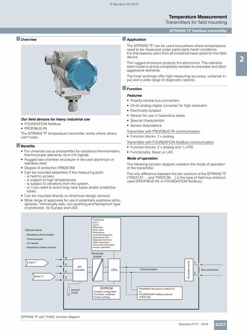
2/227Siemens FI 01 · 2018
Temperature MeasurementTransmitters for field mounting
SITRANS TF fieldbus transmitter
2
■ Overview
Our field devices for heavy industrial use• FOUNDATION fieldbus• PROFIBUS PAThe SITRANS TF temperature transmitter works where others can’t cope.
■ Benefits• For universal use as a transmitter for resistance thermometers,
thermocouple elements, or mV signals• Rugged two-chamber enclosure in die-cast aluminium or
stainless steel• Degree of protection IP66/67/68• Can be mounted elsewhere if the measuring point
- is hard to access,- is subject to high temperatures,- is subject to vibrations from the system,- or if you want to avoid long neck tubes and/or protective
tubes.• Can be mounted directly on American-design sensors• Wide range of approvals for use in potentially explosive atmo-
spheres. "Intrinsically safe, non-sparking and flameproof" type of protection, for Europe and USA
■ Application
The SITRANS TF can be used everywhere where temperatures need to be measured under particularly harsh conditions.For that reasons users from all industries have opted for this field device.
The rugged enclosure protects the electronics. The stainless steel model is almost completely resistant to sea water and other aggressive elements.
The inner workings offer high measuring accuracy, universal in-put and a wide range of diagnostic options.
■ Function
Features• Polarity-neutral bus connection• 24-bit analog-digital converter for high resolution• Electrically isolated• Version for use in hazardous areas• Special characteristic• Sensor redundance
Transmitter with PROFIBUS PA communication• Function blocks: 2 x analog
Transmitter with FOUNDATION fieldbus communication• Function blocks: 2 x analog and 1 x PID• Functionality: Basic or LAS
Mode of operation
The following function diagram explains the mode of operation of the transmitter.
The only difference between the two versions of the SITRANS TF (7NG3137-... and 7NG3138-...) is the type of field bus protocol used (PROFIBUS PA or FOUNDATION fieldbus).
SITRANS TF with TH400, function diagram
Optional inputs:
- Resistance thermometer
- Thermocouple- mV sensor
- Resistance-based sensors
Input 1
Input 2
TransformerInput 1Input 2DifferentialMean valueRedundancyTerminal temperatureEngineering units Diagnostic functionsTable linearizationPolynomial linearizationProcess calibration
A/D converter
Complex configurationCorrection coefficientFactory settings
- PROFIBUS PA protocol (7NG3137)or
- FOUNDATION Fieldbus protocol (7NG3138)
Bus connection
Ex
pow
er c
ircui
t
Electrically isolated
Internal Pt100
CommunicationCPU2
1
EEPROM
6
5
4
3
© Siemens AG 2018

2/228 Siemens FI 01 · 2018
Temperature MeasurementTransmitters for field mounting
SITRANS TF fieldbus transmitter
2
System communication
SITRANS TF with TH400, communication interface
■ Technical specifications
Input
Analog/digital conversion
• Measurement rate < 50 ms
• Resolution 24-bit
Resistance thermometer
Pt25 ... 1000 to IEC 60751/JIS C 1604
• Measuring range -200 ... +850 °C (-328 ... +1562 °F)
Ni25 ... 1000 to DIN 43760
• Measuring range -60 ... +250 °C (-76 ... +482 °F)
Cu10 ... 1000, = 0.00427
• Measuring range -50 ... +200 °C (-58 ... +392 °F)
Line resistance per sensor cable Max. 50
Sensor current Nominal 0.2 mA
Sensor fault detection
• Sensor break detection Yes
• Sensor short-circuit detection Yes, < 15
Resistance-based sensors
Measuring range 0 ... 10 k
Line resistance per sensor cable Max. 50
Sensor current Nominal 0.2 mA
Sensor fault detection
• Sensor break detection Yes
• Sensor short-circuit detection Yes, < 15
Bus terminator
Bus terminator
Segment coupler
Segment coupler
SITRANS TFwith TH400 PA
SITRANS TFwith TH400 FF
PROFIBUS PA
FOUNDATION Fieldbus
Thermocouple
to IEC 584 Measuring range
• Type B 400 ... 1820 °C (752 ... 3308 °F)
• Type E -100 ... +1000 °C (-148 ... +1832 °F)
• Type J -100 ... +1000 °C(-148 ... +1832 °F)
• Type K -100 ... +1200 °C(-148 ... +2192 °F)
• Type N -180 ... +1300 °C(-292 ... +2372 °F)
• Type R -50 ... +1760 °C (-58 ... +3200 °F)
• Type S -50 ... +1760 °C (-58 ... +3200 °F)
• Type T -200 ... +400 °C (-328 ... +752 °F)
to DIN 43710
• Type L -200 ... +900 °C (-328 ... +1652 °F)
• Type U -200 ... +600 °C (-328 ... +1112 °F)
to ASTM E988-90
• Type W3 0 ... 2300 °C (32 ... 4172 °F)
• Type W5 0 ... 2300 °C (32 ... 4172 °F)
External cold junction compensation -40 ... +135 °C (-40 ... +275 °F)
Sensor fault detection
• Sensor break detection Yes
• Sensor short-circuit detection Yes, < 3 mV
• Sensor current in the event of open-circuit monitoring
4 A
mV sensor - voltage input
Measuring range -800 ... +800 mV
Input resistance 10 M
Output
Filter time (programmable) 0 ... 60 s
Update time < 400 ms
Measuring accuracy
Accuracy is defined as the higher value of general values and basic values.
General values
Type of input Absolute accu-racy
Temperature coefficient
All 0.05 % of the measured value
0.002 % of the measured value/°C
Basic values
Type of input Basic accuracy Temperature coefficient
Pt100 and Pt1000 0.1 °C 0.002 °C/°C
Ni100 0.15 °C 0.002 °C/°C
Cu10 1.3 °C 0.02 °C/°C
Resistance-based sensors 0.05 0.002 /°C
Voltage source 10 V 0.2 V/°C
Thermocouple, type:E, J, K, L, N, T, U
0.5 °C 0.01 °C/°C
Thermocouple, type:B, R, S, W3, W5
1 °C 0.025 °C/°C
Cold junction compensation 0.5 °C
Reference conditions
Warming-up time 30 s
Signal-to-noise ratio Min. 60 dB
Calibration condition 20 ... 28 °C (68 ... 82 °F)
© Siemens AG 2018

2/229Siemens FI 01 · 2018
Temperature MeasurementTransmitters for field mounting
SITRANS TF fieldbus transmitter
2
Conditions of use
Ambient conditions
Permissible ambient temperature -40 ... +85 °C (-40 ... +185 °F)
Permissible storage temperature -40 ... +85 °C (-40 ... +185 °F)
Relative humidity 98 %, with condensation
Insulation resistance
• Test voltage 500 V AC for 60 s
• Continuous operation 50 V AC/75 V DC
Electromagnetic compatibility
NAMUR NE21
EMC 2014/30/EU Emission and Noise Immunity
EN 61326-1, EN 61326-2-5
Construction
Weight Approx. 1.5 kg (3.3 lb) without options
Dimensions See "Dimensional drawings"
Enclosure materials • Die-cast aluminum, low in cop-per, GD-AlSi 12 or stainless steel
• Polyester-based lacquer for GD AlSi 12 enclosure
• Stainless steel rating plate
Electrical connection, sensor con-nection
• screw terminals• Cable inlet via M20 x 1.5 or ½
-14 NPT screwed gland• Bus connection with M12 device
plug (optional)
Mounting bracket (optional) Steel, galvanized and chrome-plated or stainless steel
Degree of protection IP66/67 to EN 60529
Auxiliary power
Power supply
• Standard, Ex "d", Ex "nA", Ex "nL", XP, NI
10.0 ... 32 V DC
• Ex "ia", Ex "ib" 10.0 ... 30 V DC
• In FISCO/FNICO installations 10.0 ... 17.5 V DC
Power consumption < 11 mA
Max. increase in power consump-tion in the event of a fault
< 7 mA
Certificates and approvals
Explosion protection ATEX
EC type test certificate ZELM 11 ATEX 0471 X
• Type of protection "intrinsic safety i"(version: 7NG313x-1xxxx)
II 2 (1) G Ex ib [ia Ga] IIC T6 GbII 2 G Ex ib IIC T6 GbII 1D Ex ia IIIC T100 °C Da
Conformity statement ZELM 11 ATEX 0471 X
• "Operating equipment that is non-ignitable and has limited energy" type of protection(version: 7NG313x-2xxxx)
II 3 G Ex ic IIC T6/T4 GcII 3 G Ex nA IIC T6/T4 GcII 3 G Ex nA [ic] IIC T6/T4 Gc
EC type test certificate ZELM 11 ATEX 0472 X
• "Flame-proof enclosure" type of protection (version: 7NG313x-4xxxx)
II 2 G Ex d IIC T6/T5 GbII 2 D Ex tb IIIC T100 °C Db
Explosion protection: FM for USA
• FM approval FM 3017742
• Type of protection XP, DIP, NI and S(version 7NG313x-5xxxx)
XP / I / 1 / BCD / T5,T6; Type 4XDIP / II, III / 1 / EFG / T5,T6; Type 4XNI / I / 2 / ABCD / T5,T6; Type 4XS / II, III / 2 / FG T5,T6; Type 4X
Other certificates EAC Ex(GOST), INMETRO, NEPSI, KOSHA
Communication
Parameterization interface
• PROFIBUS PA connection
- Protocol A&D profile, Version 3.0
- Protocol EN 50170 Volume 2
- Address (for delivery) 126
- Function blocks 2 x analog
• FOUNDATION fieldbus connec-tion
- Protocol FF protocol
- Protocol FF design specifications
- Functionality Basic or LAS
- Version ITK 4.6
- Function blocks 2 x analog and 1 x PID
Factory setting
for SITRANS TH400 PA
Sensor Pt100 (IEC)
Type of connection 3-wire circuit
Unit °C
Failure mode Last valid value
Filter time 0 s
PA address 126
PROFIBUS Ident No. Manufacturer-specific
for SITRANS TH400 FF
Sensor Pt100 (IEC)
Type of connection 3-wire circuit
Unit °C
Failure mode Last valid value
Filter time 0 s
Node address 22
© Siemens AG 2018

2/230 Siemens FI 01 · 2018
Temperature MeasurementTransmitters for field mounting
SITRANS TF fieldbus transmitter
2
Selection and Ordering data Article No.
Temperature transmitter in field enclosurewith fieldbus communication and electrical isolation
7 N G 3 1 3 7 - 777 0 7
Click on the Article No. for the online con-figuration in the PIA Life Cycle Portal.
Integrated transmitterSITRANS TH400 with PROFIBUS PA• Without Ex protection 7 0• With Ex ia (ATEX) 7 1• With Ex nAL for zone 2 (ATEX) 7 2• Total device SITRANS TF Ex d
(ATEX + IECEx)1)7 4
• Total device SITRANS TF according to FM (XP, DIP, NI, S)1)
7 5
SITRANS TH400, with FOUNDATION fieldbus• Without Ex protection 8 0• With Ex ia (ATEX) 8 1• With Ex nAL for zone 2 (ATEX) 8 2• Total device SITRANS TF Ex d
(ATEX + IECEx)1)8 4
• Total device SITRANS TF according to FM (XP, DIP, NI, S)1)
8 5
EnclosureDie-cast aluminium AStainless steel precision casting E
Connections/cable inletScrewed glands M20x1.5 BScrewed gland s ½-14 NPT C
Mounting bracket and fastening partsNone 0Made of steel 1Stainless steel 2
Further designs Order codePlease add "-Z" to Article No. and specify Order code(s) and plain text.
Test report (5 measuring points) C11
Bus connection
• M12 device plug (metal), without mating connector
M002)
• M12 device plug (metal), with mating con-nector
M012)
Explosion protection
• Explosion protection Ex ia to INMETRO (Brazil) (only with 7NG313.-1....)
E253)
• Explosion protection Ex d to INMETRO (Brazil) (only with 7NG313.-4....)
E263)
• Explosion protection Ex nA to INMETRO (Brazil) (only with 7NG313.-2...)
E273)
• Explosion protection Ex i to NEPSI (China) (only with 7NG313.-1...)
E553)
• Explosion protection Ex d to NEPSI (China) (only with 7NG313.-4....)
E563)
• Explosion protection Ex nA to NEPSI (China) (only with 7NG313.-2...)
E573)
• Explosion protection Ex d to KOSHA (Korea) (only with 7NG313.-4...)
E703)
• Explosion protection Ex i according to EAC (Russia/Belarus/Kazahstan)(only for 7NG313.-1...)
E813)
• Explosion protection Ex d according to EAC (Russia/Belarus/Kazahstan)(only for 7NG313.-4...)
E823)
• Explosion protection Ex nA according to EAC (Russia/Belarus/Kazahstan)(only for 7NG313.-2...)
E833)
Marine approvals• Det Norske Veritas Germanischer Lloyd
(DNV GL)D01
• Bureau Veritas (BV) D02• Lloyd’s Register of Shipping (LR) D04• American Bureau of Shipping (ABS) D05
Two coats of lacquer on casing and cover (PU on epoxy)
G10
Transient protection J01
Cable gland CAPRI 1/2 NPT ADE 4F, nickle-plated brass (CAPRI 848694 and 810634) included
D57
Cable gland 1/2 NPT ADE 1F, cable diam. 6 ... 12 (CAPRI 818694 and 810534) included
D58
Cable gland 1/2 NPT ADE 4F, stainless steel (CAPRI 848699 and 810634) included
D59
Cable gland 1/2 NPT ADE 1F, cable diam. 4 ... 8.5 (CAPRI 818674 and 810534) included
D60
© Siemens AG 2018
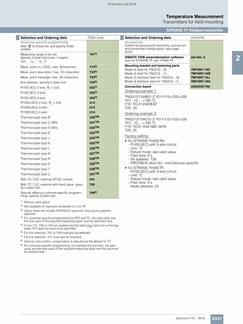
2/231Siemens FI 01 · 2018
Temperature MeasurementTransmitters for field mounting
SITRANS TF fieldbus transmitter
2
Ordering example 1:
7NG3137-0AB01-Z Y01+Y15+Y25+U03Y01: -10 ... +100 °CY15: TICA1234HEATY25: 33
Ordering example 2:
7NG3137-0AC01-Z Y01+Y15+Y25+U25Y01: -10 ... +100 °CY15: TICA 1234 ABC 5678Y25: 35
Factory setting:• for SITRANS TH400 PA:
- Pt100 (IEC) with 3-wire circuit- Unit: °C- Failure mode: last valid value- Filter time: 0 s- PA address: 126- PROFIBUS Ident No.: manufacturer-specific
• for SITRANS TH400 FF:- Pt100 (IEC) with 3-wire circuit- Unit: °C- Failure mode: last valid value- Filter time: 0 s- Node address: 22
Selection and Ordering data Order code.
Customer-specific programmingAdd "-Z" to Article No. and specify Order code(s)
Measuring range to be setSpecify in plain text (max. 5 digits):Y01: ... to ... °C, °F
Y014)
Meas. point no. (TAG), max. 8characters Y155)
Meas. point descriptor, max. 16 characters Y235)
Meas. point message, max. 32 characters Y246)
Bus address, specify in plain text Y255)
Pt100 (IEC) 2-wire, RL = 0 U027)
Pt100 (IEC) 3-wire U037)
Pt100 (IEC) 4-wire U047)
Pt1000 (IEC) 2-wire, RL = 0 U12
Pt1000 (IEC) 3-wire U13
Pt1000 (IEC) 4-wire U14
Thermocouple type B U207)8)
Thermocouple type C (W5) U217)8)
Thermocouple type D (W3) U227)8)
Thermocouple type E U237)8)
Thermocouple type J U247)8)
Thermocouple type K U257)8)
Thermocouple type L U267)8)
Thermocouple type N U277)8)
Thermocouple type R U287)8)
Thermocouple type S U297)8)
Thermocouple type T U307)8)
Thermocouple type U U317)8)
With TC: CJC: external (Pt100, 3-wire) U41
With TC: CJC: external with fixed value, spec-ify in plain text
Y50
Special differing customer-specific program-ming, specify in plain text
Y099)
1) Without cable gland2) Not available for explosion protection Ex d or XP.3) Option does not include ATEX/IECEx approval, only country-specific
approval.4) For customer-specific programming for RTD and TC, the start value and
the end value of the required measuring span must be specified here.5) If only Y15, Y23 or Y25 are ordered and the label only has to be on the tag
plate, Y01 does not have to be specified.6) For this selection, Y01 or Y09 must also be selected.7) For this selection, Y01 must also be selected.8) Internal cold junction compensation is selected as the default for TC9) For customer-specific programming, for example mV and ohm, the start
value and the end value of the required measuring span and the unit must be entered here
Selection and Ordering data Article No.
AccessoriesFurther accessories for assembly, connection and transmitter configuration, see page 2/237.
SIMATIC PDM parameterization softwarealso for SITRANS TF with TH400 PA
see Sec. 8
Mounting bracket and fastening partsMade of steel for 7NG313.-..B.. 7MF4997-1ACMade of steel for 7NG313.-..C.. 7MF4997-1ABMade of stainless steel for 7NG313.-..B.. 7MF4997-1AJMade of stainless steel for 7NG313.-..C.. 7MF4997-1AH
Connection board A5E02391790
© Siemens AG 2018

2/232 Siemens FI 01 · 2018
Temperature MeasurementTransmitters for field mounting
SITRANS TF fieldbus transmitter
2
■ Dimensional drawings
SITRANS TF with TH400, dimensions in mm (inches)
1 Sensor connection (screwed gland M20x1.5 or ½-14 NPT)2 Blanking plug3 Electrical connection (screwed plug M20x1.5 orr ½-14 NPT),
optional M12 device plug4 Terminal side, bus connection
5 Terminal side, sensor6 Protective cover (without function)7 Mounting bracket (optional) with clamp securing to
a vertical or horizontal pipe
36.5
(1.4
4)
a: max. 164 (6.46) (M20x1.5) max. 189 (7.44) (½-14 NPT)
b: max. 25 (0.98) (M20x1.5) max. 50 (1.97) (½-14 NPT)
*) Dimensions for stainless steel enclosure
144 (5.67)138* (5.43)
80 (3.15)100* (3.94)
52 (2.05)50* (1.97)
55 (2.17)
123 (4.84)
105 (4.13)
Ø 8
0 (3
.15)
Ø 50 ... 60(1.97 ... 2.36)
72 (2
.83) 68
(2.6
8)
120
(4.7
2)
237
(9.3
3)a11
7 (4
.61)50
(1.9
7)
20 (0
.79)
28 (1.10)
b
1
5 4
2
3
7
6
© Siemens AG 2018

2/233Siemens FI 01 · 2018
Temperature MeasurementTransmitters for field mounting
SITRANS TF fieldbus transmitter
2
■ Schematics
SITRANS TF with TH400, sensor connection assignment
Resistance thermometer ResistanceThermocouple
Voltage measurement
Two-wire system 1)
Three-wire system
Four-wire system
Two-wire system 1)
Three-wire system
Four-wire system
Internal cold junction compensation
Cold junction compensation with external Pt100 in two-wire system 1)
Cold junction compensation with external Pt100 in three-wire system
1) Programmable line resistance for the purpose of correction.
Mean-value/differential or redundancy generation
1 sensor in two-wire system 1)
1 sensor in three-wire system
Mean-value/differential or redundancy generation2 x two-wire system 1)
Mean value, differential or redundancy generation with internal
cold junction compensation
Mean value, differential or redundancy generation and cold junction compensation
with internal Pt100 in two-wire system 1)
Mean value, differential or redundancy generation1 resistor in two-wire system 1)
1 resistor in three-wire system
Measurement of mean value, differential and redundancy with 2 voltage sources
One voltage source
12
12
+ -
+ -
+ -
12
+ -
12
+ - + -
21+ -
+ -
12
+ -+ -
© Siemens AG 2018

2/234 Siemens FI 01 · 2018
Temperature MeasurementMultipoint temperature transmitter
SITRANS TO500
2
■ Overview
SITRANS TO500 is a multipoint temperature transmitter for mea-suring temperatures and temperature profiles using fiber optic multipoint temperature measurement lances.
■ Benefits
• Evaluation of a large number of sensors (fiber Bragg grating (FBG)) in one temperature transmitter
• Low space requirement of the measurement lances• 4 measuring lance channels per transmitter• Easy to install• PROFIBUS DP - Simple integration into control system• Fast response to temperature changes• Exact, no recalibration required due to internal reference• Also suitable for high process temperatures
■ Application
The SITRANS TO500 is used for evaluating a large number of sensors arranged on a fiber optic multipoint temperature measu-rement lance.
Up to 4 measurement lances with up to 48 sensors (fiber Bragg grating (FBG)) each can be processed simultaneously by a SITRANS TO500.
Accurate and fast determination of temperature profiles enables process optimization in terms of service life, quality and output.
Locations of excessive temperature rise are quickly and accura-tely detected, thereby preventing damage to the process, equip-ment and environment.
Wherever temperature profiles must be determined and installa-tion space is limited, the SITRANS TO500 with fiber-optic tempe-rature measurement is the right choice.
■ Design
The SITRANS TO500 multipoint temperature transmitter is loca-ted in the control cabinet in a compact aluminum enclosure for mounting onto DIN rails.
The connectors are easy to access on the front:• 4 x connector for measurement lances• 1 x connector for power supply• 1 x connector PROFIBUS DP• 1 x connector Ethernet
The status displays are also located on the front.
■ Mode of operation
In the SITRANS TO500 multipoint temperature transmitter, light is generated in the wavelength of 1500 to 1600 nm and output to the measurement lance by means of a continuously tunable la-ser light. Fiber Bragg gratings (FBG) are mounted at defined measurement points on the measurement lances. Each FBG re-flects light of a defined wavelength. The wavelength reflected by the FBGs varies as a function of temperature. The reflection at the FBG is thus a measure of the temperature at the respective measurement point. Up to 48 FBGs gratings per channel can be evaluated, depending on the temperature range.
A gas cell with fixed absorption line serves as a reference in the SITRANS TO500 and the wavelength determination is conti-nuously adjusted by it.
■ Function
The SITRANS TO500 has 4 channels which are evaluated simul-taneously. The wavelength reflected at each sensor in the multi-point temperature measurement lance depends on the tempera-ture, and this wavelength is output in the multipoint temperature transmitter. The temperature can be determined and displayed accurately at up to 48 sensors per channel. The positions of the sensors can be specified by the customer. This leads to a flexi-ble and application-specific solution for the customer.
The measured temperatures are transferred to the control sys-tem via PROFIBUS DP. The parameters of the SITRANS TO500 are set via the integrated Ethernet interface.
© Siemens AG 2018

2/235Siemens FI 01 · 2018
Temperature MeasurementMultipoint temperature transmitter
SITRANS TO500
2
■ Technical specifications
■ Selection and Ordering data Article-No.
Input
Channels 4
Measured variable Temperature
Input type Max. 48 sensors (FBGs) per channel
Characteristics Temperature-linear
Resolution 0.1 K
Measuring accuracy < 0.5 K
Repeatability < 0.5 K
Measuring cycle < 1 s
Measuring range -180 ... +800 °C(-292 ... +1472 °F) depending on the measurement lance
Unit °C
Power supply 24 V DC + 20 %
Power consumption Max. 15 W
Protection Against reverse polarity
Measuring velocity
• Measurement rate 1 Hz independent of the number of FBGs
Output
Output signal PROFIBUS DP
Optical power 1 mW per channel
Laser protection class Class 1
Rated conditions
Ambient conditions
Ambient temperature 0 ... 50 °C (32 ... 122 °F)
Storage temperature -40 ... +85 °C (-40 ... +185 °F)
Relative humidity < 80%, non condensing at 50 °C (122 °F)
Electromagnetic compatibility According to EN 61326 and NAMUR NE21
Degree of protection to EN 60529
Enclosure IP20
Design
Weight 2.4 kg (5.3 lb)
Dimensions See "Dimensional drawings"
DIN rail adapter Rear-mounted
Material Aluminum
Displays and control elements
LEDs "Power-on" (continuous light)"Status" (flashing during startup; otherwise continuous light)
Pushbutton "Reset" (system restart or address reset)
SITRANS TO500 multipoint temperature transmitter
7NG9551-4AA00-0AA0
Communication: PROFIBUS DPChannels: 4Power supply: 24 V DCOptical connection: FC/APC plugEnclosure: Aluminum, IP20
© Siemens AG 2018

2/236 Siemens FI 01 · 2018
Temperature MeasurementMultipoint temperature transmitter
SITRANS TO500
2
■ Dimensionsal drawings
SITRANS TO500, front, rear and side view; dimensions in mm (inch)
Measuring lance with FC/APC connector, pigtail and handpiece; dimensions in mm (inch)
■ Schematics
SITRANS TO500, connector assignment
130 (5.11)250 (9.84)14
0 (5
.51)
110
(4.3
3)
-GND
+
POWER
SITRANS TO500
CH1
CH2
CH3
CH4
STATUS
RESET
POWER ETHERNET PROFIBUS DP
s
Pigtail withFC/APC plug
Handpiece Glass fiber
Cable lengthInstallation
length
Ø 0
.8(0
.031
)Ø 1
0(0
.394
)
100 (3.94)
Connector measurementlances
Channel 1
Channel 2
Channel 3
Channel 4
Connector PROFIBUS DP V0/V1 RS485
Connector Ethernet RJ45 for LAN (TCP/IP)
Connector power supply24 V DC
"Power" and "Status" LEDs
"Reset" pushbutton
POWER
STATUS
POWER PROFIBUS DPETHERNET
CH1
CH2
CH3
CH4
GND
+
RESET
-
SITRANS TO500s
© Siemens AG 2018

2/237Siemens FI 01 · 2018
Temperature MeasurementAccessories
Further accessories for assembly, connection and transmitter configuration
2
Transmitter configuration forSITRANS TH / TR / TF and SITRANS TS
Cable glands and adapters for SITRANS TF and SITRANS TS
Lightning protection for SITRANS TF(SITRANS TS on request)
Connectors for SITRANS TF and SITRANS TS
Indicator for SITRANS TS500
Connection and mounting accessories for SITRANS TH
Connection and mounting accessories forfield transmitter SITRANS TF
Measurement inserts for SITRANS TS500
Measurement inserts: see SITRANS TSinsert page 2/100.
Selection and Ordering data Article No.
Modem for SITRANS TH100, TH200, TR200 and TF, with TH200 including SITPROM T parameter assignment software; 4 ... 20 mA• with USB interface 7NG3092-8KU
HART modem for all HART devices including SITRANS TH300, TH 320, TH 420, TR 300, TR 320, TR 420, TF in HART• with USB interface 7MF4997-1DB
SIMATIC PDM parameter assignment soft-ware for SITRANS TH300, TR300, TH400,TF in HART / PROFIBUS PA / FOUNDATION Fieldbus
siehe Kap. 8
IE/PB LINK PN IO siehe Kap. 7
Selection and Ordering data Article No.
M20 x 1.5 nickel-plated brass;with Ex-d approval
7MF4997-2FR
½-NPT nickel-plated brass;with Ex-d approval
7MF4997-2FU
CAPRI screw connection, M20 x 1.5 nickel-plated brass; with Ex-d approval
7MF4997-2LA
CAPRI screw connection, M20 x 1.5 stainless steel; with Ex-d approval
7MF4997-2LB
CAPRI screw connection ½-14 NPT nickel-plated brass; with Ex-d approva
7MF4997-2LC
CAPRI screw connection ½-14 NPT stainless steel; with Ex-d approval
7MF4997-2LD
Thread adapter M20x1.5 (male thread) to½-14 NPT (female thread)
} 7MP1990-0BA00
Thread adapter M20x1.5 (male thread) to G½ (female thread)
} 7MP1990-0BB00
Selection and Ordering data Article No.
Transient protector M20 x 1.5(lightning protection)
7MF4997-2DU
Transient protector ½-14 NPT(lightning protection)
7MF4997-2DV
Selection and Ordering data Article No.
Han 7D device plug made of plastic 7MF4997-2FBHan 7D device plug made of metal 7MF4997-2FC
M12 socket angled for 4 ... 6 mm cable diameter,-25 ... +85 °C (-13 ... 185 °F)
3RK1902-4CA00-4AA0
Selection and Ordering data Article No.
Digital indicator loop-powered HW05 for SITRANS TS500
A5E33119275
Selection and Ordering data Article No.
Mounting rail adapter for head-mounted transmitters (delivery quantity: 5 units)
7NG3092-8KA
Connecting cable 4-wire, 150 mm, for the sensor connection for head transmitters in the high hinged lid(set of 5)
7NG3092-8KC
Selection and Ordering data Article No.
Mounting bracket and fastening parts• made of steel for 7NG313.-..B.. and
7MP11107MF4997-1AC
• made of steel for 7NG313.-..C.. 7MF4997-1AB• made of stainless steel 304 for
7NG313.-..B.. and 7MP11107MF4997-1AJ
• made of stainless steel 304 for7NG313.-..C..
7MF4997-1AH
• made of stainless steel 316L for7NG313.-..B..
7MF4997-1AQ
• made of stainless steel 316L for7NG313.-..C..
7MF4997-1AP
Digital indicator for SITRANS TF1)
1) It is not possible to upgrade devices with Ex protection.
7MF4997-1BSConnection board for SITRANS TF A5E02391790Lithium battery for SITRANS TF280/P280 7MP1990-0AA00Cover, die-cast aluminium,without inspection window
7MF4997-1BB
Cover, die-cast aluminium,with inspection window
7MF4997-1BE
© Siemens AG 2018

2/238 Siemens FI 01 · 2018
Temperature MeasurementAccessories
Further accessories for assembly, connection and transmitter configuration
2
Connection heads Type B for SITRANS TS500 and accessory resistance thermometer
Welded-in protective tubes to DIN 43772 for SITRANS TS500
Extension tube for SITRANS TS500
Selection and Ordering data Article No
Degree of protection IP54• Connection head type: similar to BA0; aluminium;
Flange cover7MC1907-1BA
• Connection head type: Similar to BM0; plastic; screw cover
7MC1907-1BK
Degree of protection IP65• Connection head type: Similar to BB0; aluminium;
small hinged lid7MC1907-1BF
• Connection head type: Similar to BC0; aluminium; high hinged lid
7MC1907-1BL
• Connection head type: B-VA, stainless steel 7MC1907-1BV• Quick-release clamp for
connection heads BB0, BC0,degree of protection of connection head reduced to IP20, weight: 0.02 kg (0.04 lb)
7MC1907-1BS
Selection and Ordering data Article No.
Welding form 4• Tapered shank with cylindrical welding stub• For measuring insert tube with 6 mm (0.24 inch) OD• OD female thread M18 x 1.5
Up to 540 °C (1004 °F)Protective tube to DIN 43772, form 4 made of 13 CrMo 44, mat. No. 1.7335
Cone length Cmm (inch)
Protective tube length Lmm (inch)
Weightmm (inch)
• 65 (2.56) 140 (5.51) 0.3 (0.66) 7MC1905-1GA• 65 (2.56) 200 (7.87) 0.5 (1.1) 7MC1905-2GA• 125 (4.92) 200 (7.87) 0.5 (1.1) 7MC1905-3GA• 125 (4.92) 260 (10.24) 0.6 (1.32) 7MC1905-4GA
Up to 550 °C (1022 °F)Protective tube to DIN 43772, form 4 made of 6 CrNiMoTi 17122, mat. No. 1.4571
Cone length Cmm (inch)
Protective tube length Lmm (inch)
Weightkg (lb)
• 65 (2.56) 140 (5.51) 0.3 (0.66) 7MC1905-1DA• 65 (2.56) 200 (7.87) 0.5 (1.1) 7MC1905-2DA• 125 (4.92) 200 (7.87) 0.5 (1.1) 7MC1905-3DA• 125 (4.92) 260 (10.24) 0.6 (1.32) 7MC1905-4DA
Selection and Ordering data Article No.
Neck tube for high-pressure screw-in resistance thermometermade of stainless steel, mat. No. 1.4571, with thread at both ends, for measuring insert tube with 6 mm (0.24 inch) OD
Neck tube length
Total length of the resistance thermometer,without connection head
Protective tube length
Weight
mm (inch) mm (inch) mm (inch) kg (lb)
• 135 (5.31) 395 (15.55) 260 (10.24) 0.14 (0.31) 7MC1906-1AA• 165 (6.50) 305/365 (12.01/14.37) 140/200 (5.51/7.87) 0.15 (0.33) 7MC1906-2AA• 195 (7.68) 395 (15.55) 200 (7.87) 0.18 (0.40) 7MC1906-3AA• 225 (8.86) 365 (14.37) 140 (5.51) 0.20 (0.44) 7MC1906-4AA• 255 (10.04) 395 (15.55) 140 (5.51) 0.22 (0.49) 7MC1906-5AA
© Siemens AG 2018

2/239Siemens FI 01 · 2018
Temperature MeasurementAccessories
Further accessories for assembly, connection and transmitter configuration
2
Connection heads Type A and accessory for straight thermocouple
■ Connection heads
Connection head, Type A (without terminal block and terminals) for protective tube diameter (bore = protective tube diameter +0.5 mm (0.02 inch))
■ Installation accessories for connection heads
• Terminal block• Terminal• Set of gaskets• Set of washers• Mounting flange• Threaded sleeve
Selection and Ordering data Article No.
Metallic protective tubes for straight thermocouple elements according to DIN 43733
X 10 CrAl 24, material No. 1.4762; 22 mm x 2 mm (; 0.87 inch x 0.08 inch), 0.55 ... 1.10 kg (1.21 ... 2.42 lb), dishedNominal lengthin mm (inch):
Protective tube lengthin mm (inch):
• 500 (19.7) 520 (20.5) 7 M C 2 9 0 0 - 1 D A• 710 (28.0) 730 (28.7) 7 M C 2 9 0 0 - 2 D A• 1000 (39.4) 1020 (40.2) 7 M C 2 9 0 0 - 3 D A
X 10 CrAl 24, material No. 1.4749; 26 mm x 4 mm (; 1.02 inch x 0.16 inch), 1.25 ... 2.20 kg (2.76 ... 4.85 lb), dishedNominal lengthin mm (inch):
Protective tube lengthin mm (inch):
• 500 (19.7) 520 (20.5) 7 M C 2 9 0 0 - 1 E C• 710 (28.0) 730 (28.7) 7 M C 2 9 0 0 - 2 E C• 1000 (39.4) 1020 (40.2) 7 M C 2 9 0 0 - 3 E C
X 15 CrNiSi 25 20, material No. 1.4841; 22 mm x 2 mm (; 0.87 inch x 0.08 inch), 1.05 kg (2.31 lb), dishedNominal lengthin mm (inch):
Protective tube lengthin mm (inch):
• 1000 (39.4) 1020 (40.2) 7 M C 2 9 0 0 - 3 FA
CrAl 205 (Megapyr), material No. 1.4767; 22 mm x 2 mm (; 0.87 inch x 0.05 inch), 0.55 ... 1.10 kg (1.21 ... 2.42 lb)Nominal lengthin mm (inch):
Protective tube lengthin mm (inch):
• 500 (19.7) 520 (20.5) 7 M C 2 9 0 0 - 1 H A• 710 (28.0) 730 (28.7) 7 M C 2 9 0 0 - 2 H A• 1000 (39.4) 1020 (40.2) 7 M C 2 9 0 0 - 3 H A
Selection and Ordering data Article No.
Thermocouples elements for straight thermocouple according to DIN 43733
Base-metal thermocouple with insulating beadsWire diameter 3 mm (0.12 inch)Ni Cr/Ni, to 1000 °C (maximal 1300 °C),(to 1832 °F (max. 2372 °F))0.55 ... 2.10 kg (1.21 ... 4.63 lb)Nominal length L1 inmm (inch):
Thermocouple length L2 in mm (inch):
• 500 (19.7) 540 (21.3) 7 M C 2 9 0 3 - 1 C A• 710 (28.0) 750 (29.5) 7 M C 2 9 0 3 - 2 C A• 1000 (39.4) 1040 (40.9) 7 M C 2 9 0 3 - 3 C A
Selection and Ordering data Article No.
Connection head, Type A,(without terminal block and terminals)1 Cable inlet, degree of protection IP53, 0.35 kg (0.77 lb)
Cast light alloyfastener, unscrewablefor protective tube diameter in mm (inch)(bore = protective tube diam. +0.5 mm) (0.02 inch):• 22 (0.87) 7 M C 2 9 0 5 - 1 A A• 26 (1.02) 7 M C 2 9 0 5 - 1 B A
Cast light alloyhigh hinged coverfor protective tube diameter in mm (inch)(bore = protective tube diam. +0.5 mm) (0.02 inch):• 22 (0.87) 7 M C 2 9 0 5 - 4 A A• 26 (1.02) 7 M C 2 9 0 5 - 4 B A
Selection and Ordering data Article No.
Mounting accessories
Terminal block without terminals 7 M C 2 9 9 8 - 1 A Afor base-metal thermocouples; 0.06 kg (0.13 lb)
Terminal 7 M C 2 9 9 8 - 1 B Afor base-metal thermocouples; 0.01 kg (0.02 lb)
Set of gaskets (100 off) 7 M C 2 9 9 8 - 1 C Afor the connection head cover;0.01 kg (0.02 lb)
Set of washers (100 off) 7 M C 2 9 9 8 - 1 C B
for the terminal block; 0.01 kg (0.02 lb)
Mounting flange, adjustable; made of GTW• for protective tube outer diameters
22 mm (0.87 inch); 0.35 kg (0.77 lb)7 M C 2 9 9 8 - 2 C B
• for protective tube outer diameters26 mm (1.02 inch); 0.32 kg (0.71 lb)
7 M C 2 9 9 8 - 2 C C
Threaded sleeveGas-tight up to 1 bar (14.5 psi), adjustable, materiall No. 1.0718, with gasket; 0.40 kg (0.88 lb)• for protective tube outer diameters
22 mm (0.87 inch), G17 M C 2 9 9 8 - 2 D B
• for protective tube outer diameters26 mm (1.02 inch), G1
7 M C 2 9 9 8 - 2 D C
© Siemens AG 2018

2/240 Siemens FI 01 · 2018
Temperature Measurement
Notes
2
© Siemens AG 2018