catalog harmony control relays
TRANSCRIPT

www.se.com
Catalog | October 2021
Near Field Communication andconventional Control Relays
Harmony Control Relays

Discover HarmonyAdvanced operator interface and industrial relaysHarmony operator interface and industrial relays enhance operational efficiency and equipment availability across industrial and building applications. Harmony includes intelligent connected products and edge terminals that visualize, gather and process data, enabling informed operator decisions
Explore our offer - Harmony Push Buttons and Switches - Harmony HMI Operator Terminals, IPC and EdgeBox - Harmony Signaling Devices - Harmony Electrical Relays - Harmony Safety
Harmony

Find your catalog
> With just 3 clicks, you can access the Industrial Automation and Control catalogs, in both English and French > Consult digital automation catalogs at Digi-Cat Online
Select your training
> Find the right Training for your needs on our Global website > Locate the training center with the selector tool, using this link
Quick access to product information
Get technical information about your product
Each commercial reference presented in a catalog contains a hyperlink. Click on it to obtain the technical information of the product:
– Characteristics, Dimensions and drawings, Mounting and clearance, Connections and schemas, Performance curves
– Product image, Instruction sheet, User guide, Product certifications, End of life manual
• Up-to-date catalogs• Embedded product selectors,360° pictures• Optimized search by commercial references

1
General contents
Harmony Control Relays
b General Presentation ............................................................................... page 2
Selection guide . . . . . . . . . . . . . . . . . . . . . . . . . . . . . . . . . . . . . . . . . . . . . . . page 4
b 3-phase supply control relays v RM17
- RM17TG .............................................................................................. page 12 - RM17TT, RM17TA, RM17TU, and RM17TE ....................................... page 20 - RM17UB3 ............................................................................................ page 26
v RM22 - RMNF22 (NFC Multifunction) .............................................................. page 14 - RM22TA, RM22TU, RM22TR, and RM22TG ....................................... page 16
v RM35 - RM35TF .............................................................................................. page 24 - RM35TM (Motor temperature control relays) ...........................................page 30 - RM35UB3 ............................................................................................ page 26
b 1-phase voltage control relays v RM17UAS and RM17UBE ........................................................................ page 34 v RM22UA and RM22UB ............................................................................. page 40 v RM35UA ................................................................................................... page 38
b 1-phase current control relays v RM17JC (with integrated current transformer) .......................................... page 44 v RM22JA .................................................................................................... page 46 v RM35JA .................................................................................................... page 46
b Liquid level control relays - RM22LA and RM22LG......................................................................... page 52 - RM35L ................................................................................................. page 56
b Pump control relays - RM35BA .............................................................................................. page 60
b Frequency control relays - RM35HZ .............................................................................................. page 62
b Speed control relays - RM35S ................................................................................................ page 64
b Temperature control relays for elevator machine rooms and 3-phase supplies - RM35AT .............................................................................................. page 68
b Accessories for Liquid level control relays - Electrode holders and probes .............................................................. page 70
b Product reference index ........................................................................ page 72

2
General presentation Harmony Control RelaysNear Field Communication and conventional Control Relays
Harmony Control Relays Harmony Control relays monitor and detect abnormal operating conditions concerning phase, current, voltage, frequency, speed, or temperature. The relays inform users of abnormal conditions, and allow them to initiate the necessary corrective actions before serious and costly breakdowns can occur. By monitoring energy network statuses, they enable both electrical and mechanical load control.
RM17T, RMNF22, RM35L, RM17J Harmony Control Relays
They are suitable for a wide range of applications: b Hoisting: construction cranes, harbor cranes b Packaging: motor voltage, current overload b Lifts: construction lifts, passenger lifts, escalators b Textile: motor voltage, current overload b Water: liquid level on water tank at water and waste water recycling plant
Depending on the product model, control relays are categorized into 8 product families:
b 3-phase control b Current control b Voltage control b Frequency control b Speed control b Lift temperature control b Level control b Pump control
Harmony Control relay functions
MonitoringControl relays monitor physical and electrical values. They measure variable signals such as phase (presence, sequence and symmetry), voltage, current, and frequency. They also control liquid levels and process operating rates.
InformingControl device outputs provide users with electrical information. In addition, setting faults are signaled by simultaneous flashing of all LEDs.
ProtectingIntegrated in the control circuits of automated systems, they enable automatic shutdown management and provide fault information, thus protecting the equipment.
ManagingWhen the power is switched on, the control relays are inhibited to enable correct measurement circuit setting. The outputs operate with positive logic, the contact or contacts being closed under normal conditions and opening as soon as a fault or power supply loss is detected.
CommissioningWhen the diagnostic button is used, the downstream circuit can be closed immediately without sending a fault input signal to the relays. This shortens the testing time during commissioning and troubleshooting.
Harmony Control Relays A simple approach to monitoring your equipment

3
Harmony Control Relays A simple approach to monitoring your equipment
Harmony Control relays with unique design and features> Compact modular sizes: 17.5 mm/0.69 in., 22.5 mm/0.88 in., 35 mm/1.38 in.> Adapted for industrial and building control panels> True RMS measurement that minimizes the possibility of unexpected trips from
highly polluted networks (except RM17TG and RM22TG)> Diagnostic button to check the downstream circuit immediately and reduce
commissioning and troubleshooting time (1)> IP50 lead-sealable settings protection cover helps prevent dust and unintended
human intervention> Status indication by LEDs, additional dial pointer LED for easy setup in dark
conditions (1), and power “On” status indication when relay is ready to perform
Dial pointer LED indicator
Diagnostic button
> Optimization of power supplies> Worldwide certification:
®
Harmony Control relay with NFC (2) technology
Simplify product selection> One product reference with 7 control functions: Phase loss, Phase sequence,
Asymmetry, Overvoltage, Undervoltage, Overfrequency, and Underfrequency
Achieve unprecedented accuracy> Digitized setting eliminate the need for screw driver> Timed delay can be set by minute, second or millisecond
Fault diagnosis> Fault status indication by LEDs> Real time fault analysis and Historical fault data are viewable in APP
Superior security> 4 digit password protection
(1) Available in RM35JA32MR, RM35JA32MT, and all RM22 references.(2) Near Field Communication
General presentation (continued)
Harmony Control RelaysNear Field Communication and conventional Control Relays
Harmony Control Relays To control your machines and processes of the future
NFC Control Relay: As simple as1 Install2 Open app3 Set parameters
Scan here to check out the NFC Control Relay video

6.0
Harmony Control RelaysNear Field Communication and conventional Control Relays
Selection guide
Application 3-phase control 3-phase control
Functions - Phase sequence- Phase loss
With/without memory selection in the app. - Phase sequence - Phase loss - Asymmetry - Undervoltage - Overvoltage - Under-frequency - Over-frequency
- Phase sequence - Phase loss
- Phase sequence- Phase loss
- Phase sequence- Phase loss- Overvoltage and undervoltage
- Phase sequence- Phase loss- Undervoltage
- Phase sequence- Phase loss- Asymmetry
- Phase sequence- Phase loss- Asymmetry
- Phase sequence- Phase loss- Asymmetry - Overvoltage and undervoltage
- Overvoltage and undervoltage between phases- Overvoltage and undervoltage between phases and neutral- Absence of neutral/phase
- Phase sequence- Phase loss- Motor temperature
Values controlled 208…480 V a 208…440 V a
208…480 V a 208…480 V a 208…480 V a 200…240 V a 380…480 V a
208…480 V a 200…240 V a 380…480 V a
208…480 V a 200…240 V a 380…480 V a
208…480 V a 220…480 V a
220…480 V a 208…480 V a 120…277 V a
208…480 V a Motor temperature: PTC probe resistance 15 Ω to 3100 Ω
Output contact rating 1 or 2 CO 5 A 2 CO 8 A (individually configurable)
2 CO 8 A 1 CO 5 A 2 CO 8 A 1 CO 5 A 2 CO 8 A 1 CO 5 A 2 CO 8 A 1 or 2 CO 5 A 1 CO or 2 CO 5A 2 NO 5 A
Supply voltage Self-powered 208…480 V a line to line,120…277 V a line to neutral
Self-powered Self-powered 24-240V z
Time delay – 0.1s...60 min – 0.1…30 s 0.1…10 s – 0.1…10 s 0.1…30 s 0.1…10 s 0.3…30 s –
Size (mm/in.) 17.5/0.69 22.5/0.885 22.5/0.885 17.5/0.69 22.5/0.885 17.5/0.69 22.5/0.885 17.5/0.69 22.5/0.885 17.5/0.69 or 35/1.377 17.5/0.69 or 35/1.377
35/1.377
Modular relay type RM17TG00 RM17TG20
RMNF22TB30 RM22TG20 RM17TT00 RM22TR31RM22TR33
RM17TU00 RM22TU21RM22TU23
RM17TA00 RM22TA31RM22TA33
RM17TE00RM35TF30
RM17UB310RM35UB330 RM35UB3N30
RM35TM50MW RM35TM250MW
Pages 12 14 16 20 16 20 16 20 16 20 26 30
More technical Information on www.se.comMore technical Information on www.se.com
4 5

Application 1-phase voltage control 1-phase voltage control
Functions - Undervoltage (without memory)
- Overvoltage or undervoltage (with/without memory) - Overvoltage (without memory) - Overvoltage (with/without memory)- Undervoltage (with/without memory)- Overvoltage and undervoltage in window mode (with/without memory)
- Overvoltage and undervoltage in window mode (without memory)
Values controlled 220 V a 9…15 V c20…80 V z65…260 V z
0.05…5 V z1…100 V z15…600 V z
0.05…5 V z1…100 V z15…500 V z
0.05…5 V z1…100 V z15…500 V z
20…80 V z65…260 V z
80…300 V z
Output contact rating 1 CO 5 A 1 CO 5 A 2 CO 5 A 2 CO 8 A 2 CO 8 A 1 CO 5 A 2 CO 8 A
Supply voltage Self-powered Self-powered 24…240 V z 24…240 V z 24…240 V z380…415 V a
Self-powered 110…240 V z
Time delay 3…15 min 0.1…10 s 0.3…30 s – 0.1…30 s 0.1…10 s 0.1…30 s
Size (mm/in.) 17.5/0.69 17.5/0.69 35/1.377 22.5/0.885 22.5/0.885 17.5/0.69 22.5/0.885
Modular relay type RM17UAS15315M RM17UAS14 RM17UAS16RM17UAS15
RM35UA11MW RM35UA12MW RM35UA13MW
RM22UA21MRRM22UA22MRRM22UA23MR
RM22UA31MRRM22UA32MRRM22UA33MRRM22UA33MT
RM17UBE16 RM17UBE15
RM22UB34
Pages 34 34 38 40 40 34 40
Harmony Control RelaysNear Field Communication and conventional Control Relays
Selection guide (continued)
54
More technical Information on www.se.comMore technical Information on www.se.com
6 7

Application 1-phase current control 1-phase current control
Functions Integrated current transformer No integrated current transformer No integrated current transformer - Overcurrent (without memory) - Overcurrent (with/without memory)
- Undercurrent (with/without memory)- Overcurrent (with/without memory)- Undercurrent (with/without memory)- Overcurrent and undercurrent in window mode (with/without memory)
Values controlled 2…20 A 4 mA...1A 2…500 mA0.15…15 A
4 mA...1 A150 mA...15 A
Output contact rating 1 CO 5 A 2 CO 8 A 2 CO 5 A 2 CO 8 A
Supply voltage 24…240 V z 24…240 V z 24…240 V z 24…240 V z380…415 V a
Time delay – Inhibition time delay upon startup 1…20 sTime delay 0.3…30 s
0.1…30 s
Size (mm/in.) 17.5/0.69 22.5/0.885 35/1.377 22.5/0.885, 35/1.377
Modular relay type RM17JC00MW RM22JA21MR RM35JA31MWRM35JA32MW
RM22JA31MRRM35JA32MRRM35JA32MT
Pages 44 46 50 46
Harmony Control RelaysNear Field Communication and conventional Control Relays
Selection guide (continued)
76
More technical Information on www.se.comMore technical Information on www.se.com
8 9

98
Selection guide (continued) Harmony Control RelaysNear Field Communication and conventional Control Relays
Application Level control Pump control Frequency control Speed control Temperature control for elevator machine rooms and 3-phase supplies
Functions By resistive probes By resistive probes By resistive probes By discrete sensor 3-phase and 1-phase - Over-frequency and under-frequency (with/without memory)
- Over or under operating rate/speed (with/without memory)
- Elevator Machine room temperature-Over temperature and under temperature
- Elevator Machine room temperature-Over temperature and under temperature- Phase loss and phase sequence
- Level 1/Level 2- Fill operation- Empty operation- Standard sensitivity
- Level 1/Level 2- Fill operation- Empty operation- Low sensitivity- Standard sensitivity- High sensitivity
- Level 1/Level 2- Fill operation- Empty operation- Low sensitivity- Standard sensitivity- High sensitivity
- Empty or fill- Input for discrete sensor AON: Contact/PNP/NPN
- Overcurrent and undercurrent- Phase sequence on 3-phase supply- Phase loss on 3-phase supply
Values controlled 5…100 kΩ 0.25…5 kW5…100 kW0.05…1 MW
0.25…5 kΩ5…100 kΩ0.05…1 MΩ
– Current: 1…10 A3-phase 208…480 V a1-phase 230 V a
Mains supply: 50 or 60 HzHigh threshold: - 2…+ 10 HzLow threshold: - 10…+ 2 Hz
Time controlled between pulses:0.05…0.5 s, 0.1…1 s,0.5…5 s, 1…10 s0.1…1 min, 0.5…5 min, 1…10 min
TemperatureLow threshold: - 1…11 °CHigh threshold: 34…46 °C
TemperatureLow threshold: - 1…11 °CHigh threshold: 34…46 °C3-phase supplies 208…480 V a
Output control rating 1 CO 8 A 2 CO 5 A 2 CO 8 A 1 CO 5 A 1 CO 5 A 2 CO 5 A 1 CO 5 A 1 CO 5 A or 2 NO 5 A
2 NO 5 A
Supply voltage 24…240 V z380…415 V a
24…240 V z 24…240 V z 24…240 V z 208…480 V a , 3-phase 230 V a, 1-phase
120…277 V a 24…240 V z 24…240 V z 24…240 V z
Time delay – 0.1…5 s 0.1…30 s 0.1…5 s Inhibition time delay upon startup 1…60 sTime delay 0.1…10 s
0.1…10 s Inhibition time delay upon startup 0.6…60 s
1…10 s
Size (mm/in.) 22.5/0.885 35/1.377 22.5/0.885 35/1.377 35/1.377 35/1.377 35/1.377 35/1.377 35/1.377
Modular relay type RM22LG11MRRM22LG11MT
RM35LM33MW RM22LA32MR RM35LV14MW RM35BA10 RM35HZ21FM RM35S0MW RM35ATL0MWRM35ATR5MW
RM35ATW5MW
Pages 52 56 52 56 60 62 64 68 68
More technical Information on www.se.comMore technical Information on www.se.com
10 11

12
Presentation, description
Harmony Control Relays3-phase supply control relaysRM17TG
PresentationRM17TGp0 measurement and control relays for 3-phase supplies monitor the correct sequencing of phases L1, L2, and L3 and the total loss of two or more of these phases.
Functions RM17TGSequence of phases L1, L2, and L3Phase loss
Function performedFunction not performed
Depending on the model, RM17TG control relays: b Accept different nominal 3-phase voltage values v 208…480 V a for RM17TG00 v 208…440 V a for RM17TG20 b Are designed for clip-on mounting on a 5 rail
The control status is indicated by an LED.
Applications b Control for connection of moving equipment (site equipment, agricultural
equipment, refrigerated trucks) b Control against reverse motor operation (lifting, handling, elevators,
escalators, etc.) b Control of sensitive 3-phase supplies b Emergency power supply switching in abnormal conditions
DescriptionRM17TG00 , RM17TG20
1 Spring for clip-on mounting on 35 mm/1.38 in. 5 railL1 L2 L3
12 11 14
R
1 1
L1 L2 L3
24 21 22
12 11 14
R
RM17TG00
RM17TG00
R Yellow LED: indicates relay output status
RM17TG20

13
Operation, references
Operating principle3-phase supply control relays monitor:
b Correct sequencing of phases L1, L2, and L3 b Fault signaling by LEDs b Total loss of two or more of the phases
Function DiagramOutput 11-14, 21-24 openOutput 11-14, 21-24 closed
RM17TGp0 v Sequence of phases L1, L2, and L3 v Phase loss
100%
100V
100V
100V
0%
100%
0%
100%
0%
R - R1/R2 Tr Tr Tr TrTr
L3
L2
Phase L1
Phase L2
Phase L3
Relays
Phase controlThe relays monitor:
b That the phase sequence and voltages are correct (> 183 V), the output relay(s) is/are closed and the yellow LED is on.
b If a sequencing fault or total loss of two or more phases is detected (detected as soon as two of the voltages drops below 100 V), the relay opens instantly and the LED goes off.
b On energization of the device with a detected measured fault, the relay stays open.
Note: Tr: response time on detection of a fault
ReferencesFunction Rated 3-phase
supply voltage Output Reference Weight
V kg/lb b Phase sequence b Phase loss
208…480 a 1 CO 5 A RM17TG00 0.080/ 0.176
208…440 a 2 CO 5 A RM17TG20 0.085/ 0.187
Harmony Control Relays3-phase supply control relaysRM17TG
RM17TG00 RM17TG20
PF15
3400
B
PF15
3401
A

14
Presentation, description
Harmony Control RelaysMultifunction 3-phase control relays RMNF22
RMNF22
PresentationThe Near Field Communication (NFC) control relay is designed to monitor the following functions in 3-phase power networks and upon detection of faults, the relay contacts can be opened or closed with or without a set timing period.
b Sequence of phases (L1, L2, L3, N) b Phase loss b Asymmetry b Undervoltage b Overvoltage b Under-frequency b Over-frequency
NFC control relay provides simplified product selection and inventory management. It monitors 3-phase or 3-phase + neutral networks with 4 indication LEDs that display exact faults occurred during the process. The mobile app, Zelio NFC, is Android enabled and can be downloaded onto your phone from Google Play. With this mobile app, accurate parameter settings can be achieved and the 2 relay outputs can be individually configured.
Applications b Control against reverse motor operation (lifting, handling, elevators, escalators, etc.) b Control of sensitive 3-phase supplies b Emergency power supply switching in abnormal conditions b HVAC and pumping control panels
DescriptionRMNF22
1 Pairing Indication LED2 Phase Loss (PL) fault indication LED (Red continuous) or Phase Sequence (PS)
fault indication LED (Red blinking)3 Undervoltage (UV) fault indication LED (Red continuous) or Overvoltage (OV)
fault indication LED (Red blinking)4 Asymmetry (Asym) fault indication LED (Red continuous)5 Under-frequency (UF) fault indication LED (Red continuous) or Over-frequency (OF)
fault indication LED (Red blinking)6 Output 2 indication LED (Amber)7 Output 1 indication LED (Amber)8 Power Supply indication LED (Green)9 NFC antenna location
NFC control relay mobile application To use NFC control relay, an Android phone with NFC feature and Android OS (version 4.4 and above) are required. The Zelio NFC app can be downloaded in the mobile with one of the following methods:
b Align the mobile phone NFC antenna to the product NFC antenna. This will take you to the Google Play page for downloading the app.
b Go to Google Play and search for “Zelio NFC”. b Scan the below QR code to download the Zelio NFC app.
With Zelio NFC app installed in your mobile device, you can retrieve/configure and lock/unlock the product settings, and diagnose product status. The related function diagrams, wiring diagram and Quick Start Guide can be obtained from the app. They feature:
b Read, write, clone settings b Easy auto-configure settings b Configuration of up to 10 alarms with different monitoring functions b Alarm combination with logic (AND, OR, NOT) for relay output b User defined positive & negative logic (relay output) b Simulator to check logic validity in alarm combination b Diagnose feature for displaying historical faults through event logging b Share settings via multiple channels depending on the phone (email, WhatsApp, etc.) b Secured with password protection
NFC Control Relay
L1
N
L2 L3
12 11 14
22 21 24
RMNF22TB30
Asym
R2
R1
Un
PL /-PS-
UV /-OV-
UF /-OF-
NFC
12345678
9
NFC control relay with Smartphone mobile app

15
Operation,references
Operating principleRMNF22Phase loss + Phase sequence
Phase L1
Phase L2
Phase L3
Alarm
L2
L3
Tr Tr Tr Tr
Alarm triggeredAlarm not triggered
The relay monitors its own supply voltage Un: b Correct sequence of three phases b Phase loss of at least one of the three phases b Phase loss or phase sequence values can be set individually using the
app. b If a sequencing or phase loss fault is detected, the relay output opens or
closes based on user Alarm settings in app.
Note: Tr: response after crossing of threshold (< 300 ms)
Undervoltage + Overvoltage
Alarm
<Tt<Tt
Tt Tt
Hysteresis
Hysteresis
Threshold >U
Threshold <U
Phases L1/L2/L3
With on delay Alarm triggeredAlarm not triggered
The relay monitors its own supply voltage Un: b Under Voltage or Over Voltage b An adjustable time delay on threshold crossing provides immunity to
transients, and helps prevent spurious triggering of the output relay. b If a voltage fault is detected, the relay opens or closes at the end of time
delay set as On-delay or Off-delay by the user through the app.
Note: Tt: time delay after crossing of threshold (adjustable in Zelio NFC app)
Asymmetry
Phase L1
With on delay
Phase L2
Phase L3
Alarm
<Tt
Tt Tt Tt
Hysteresis0%
Asymmetry
Alarm triggeredAlarm not triggered
The relay monitors its own supply voltage Un: b Asymmetry b If an asymmetry fault is detected, the relay opens or closes at the end of
time delay set by the user through the app.
Note: Tt: time delay after crossing of threshold (adjustable in Zelio NFC app)
Under-frequency + Over-frequency
Tt Tt
<Tt
Alarm
Hysteresis
Hysteresis
Threshold >F
Threshold <F
Frequency L1/L2/L3
With on delay Alarm triggeredAlarm not triggered
The relay monitors its own supply voltage Un: b Under-frequency or Over-frequency b If a frequency value exceeding the threshold is detected, the relay
opens or closes at the end of the time delay set as On-delay or Off-delay by the user through the app.
Note: Tt: time delay after crossing of threshold (adjustable in Zelio NFC app)
Alarm combination using Boolean logicWith Zelio NFC App, it is possible to combine different alarms using AND, OR and NOT logic to form unique monitoring combinations for each of the relay outputs. A Simulator is also available to verify the validity of the overall logic.
Harmony Control RelaysMultifunction 3-phase control relaysRMNF22
RM
_528
_CPM
GU
1800
1
RMNF22TB30
ReferencesFunction Measurement
rangeTime delay Output Reference Weight
V kg/lb b Phase sequence b Phase loss b Asymmetry b Undervoltage b Overvoltage b Under-frequency b Over-frequency
208...480 a Adjustable 0.1 s…60 min(Phase loss and Phase sequence instant trigger)
2 CO 8 A (individually configurable)
RMNF22TB30 (1)
0.125/ 0.276
(1) With or Without memory mode is selectable for all functions in the app.

16
PresentationRM22 multifunction Harmony control relays monitor the following functions on 3-phase supplies:Functions RM22TA RM22TU RM22TR RM22TG
Sequence of phases L1, L2, and L3Phase lossAsymmetryUndervoltageOvervoltage and undervoltage
Function performedFunction not performed
Depending on the model, RM22T control relays: b Accept different nominal 3-phase voltages: up to 480 Vab Monitor their own power supply measured as a true rms value (except RM22TG)b Are designed for clip-on mounting on a 5 rail
They feature a:b Sealable cover to help protect the settingsb Diagnostic button for load circuit testingb Relay output status LEDb Fault detection indication LED b Dial pointer LED indicator for relay power ON statusb Relay output On-delay or Off-delay
Applicationsb Control for connection of moving equipment (site equipment, agricultural equipment, refrigerated trucks)b Control against reverse motor operation (lifting, handling, elevators, escalators, etc.)b Control of sensitive 3-phase suppliesb Emergency power supply switching in abnormal conditions
DescriptionRM22TA, RM22TU, RM22TR, RM22TG
1a Voltage range selector switch1b Voltage range/On-Off delay selector2 Time delay adjustment potentiometer Tt3a Asymmetry threshold setting potentiometer Asym3b Undervoltage setting potentiometer <U3c Overvoltage setting potentiometer >U4 Diagnostic button
Operating principleMultifunction 3-phase supply control relays monitor:
b Product being powered by L1 and L3 b Correct sequencing of phases
L1, L2, and L3 b LED indication for relay output status and
fault detection (except phase disconnection) b Phase loss, including in the case of voltage
regeneration b Undervoltage from - 2…- 20% of the supply
voltage Un b Overvoltage from 2…20% of the supply
voltage Un b Asymmetry from 5…15% of the supply
voltage Un
Function DiagramOutput 11-14, 21-24 openOutput 11-14, 21-24 closed
Voltage switch operation: v Set the switch to 3-phase supply voltage Un. v The position of this switch is taken into account on energization of the device. v If the switch position is changed while the device is operating, all the LEDs flash
but the product continues to operate normally with the voltage selected at the time of energization preceding the change of position.
v If the switch is returned to the original position selected prior to the last energization, the LEDs return to their normal state.
Presentation, description, operation
Harmony Control RelaysMultifunction 3-phase control relays RM22TA, RM22TU, RM22TR, and RM22TG
RM22T
L1 L2
12 11 14
22 21 24
R
RM22TA31
DIAGNOSTIC
Def
200208
220
240
8
5
10 12
15%
Asym
L3
Tt
0,1 30s
5
10 20
25
1a23a
4
RM22TA
L1 L2 L3
12 11 14
22 21 24
R
RM22TU23
DIAGNOSTIC
Def
380400 415
440
480
-2
-4-6
-8 -14-16-18
-20%
<U
1a3b
4
RM22TU
L1 L2 L3
12 11 14
22 21 24
R
RM22TG20
DIAGNOSTIC
Un
4
RM22TG
L1 L2 L3
12 11 14
22 21 24
2
46
8 1416 18
20%
R
>U
RM22TR31
DIAGNOSTIC
-2
-4-6
-8 -14-16 -18
-20%
<U
Def
240220
208200
240220
208200
Tt
ON
DEL
AY
OFF
DEL
AY
0,1 30s
5
10 20
25
1b
3c3b4
RM22TR
Un Green LED: indicates that supply to the product is onR Yellow LED: indicates relay output statusDEF Yellow LED: indicates fault detection
17
Operation (continued)
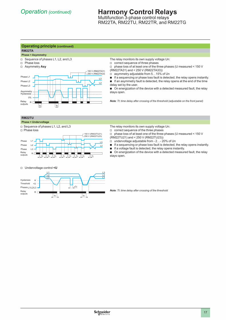
Operating principle (continued)RM22TAPhase + Asymmetry v Sequence of phases L1, L2, and L3 v Phase loss v Asymmetry Asy
L2
L3
0%
Tt TtR
150 V (RM22TA31)250 V (RM22TA33)
Phase L3
Phase L2
Phase L1
HysteresisAsymmetry
Relay outputs
The relay monitors its own supply voltage Un: v correct sequence of three phases v phase loss of at least one of the three phases (U measured < 150 V
(RM22TA31) and < 250 V (RM22TA33)) v asymmetry adjustable from 5…15% of Un b If a sequencing or phase loss fault is detected, the relay opens instantly. b If an asymmetry fault is detected, the relay opens at the end of the time
delay set by the user. b On energization of the device with a detected measured fault, the relay
stays open.
Note: Tt: time delay after crossing of the threshold (adjustable on the front panel)
RM22TUPhase + Undervoltage
v Sequence of phases L1, L2, and L3v Phase loss
150 V (RM22TU21)250 V (RM22TU23)
L3
L2
R
L1
L2
L3
Tr Tr Tr Tr Tr Tr Tr Tr
Phase
Phase
Phase
Relay outputs
The relay monitors its own supply voltage Un: v correct sequence of the three phases v phase loss of at least one of the three phases (U measured < 150 V
(RM22TU21) and < 250 V (RM22TU23)) v undervoltage adjustable from - 2…- 20% of Un b If a sequencing or phase loss fault is detected, the relay opens instantly. b If a voltage fault is detected, the relay opens instantly. b On energization of the device with a detected measured fault, the relay
stays open.
Note: Tt: time delay after crossing of the threshold
v Undervoltage control <U
R
L1/L2/L3
L1L2L3
L2L3
L1
<UH
Tr
<Tr
Tr
ThresholdHysteresis
Relay outputs
Phases
Harmony Control RelaysMultifunction 3-phase control relaysRM22TA, RM22TU, RM22TR, and RM22TG

18
Operation (continued) Harmony Control RelaysMultifunction 3-phase control relaysRM22TA, RM22TU, RM22TR, and RM22TG
Operating principle (continued)RM22TRPhase + Undervoltage/overvoltage v Sequence of phases L1, L2, and L3 v Phase loss
The relay monitors its own supply voltage Un: v phase loss (U measured <150 V (RM22TR31) and
< 250 V(RM22TR33)) v undervoltage and overvoltage b An adjustable time delay on threshold crossing provides immunity to
transients, and helps prevent spurious triggering of the output relay. b If a voltage fault is detected, the relay opens at the end of the time delay
set as On-delay or Off-delay by the user. b On energization of the device with a detected measured fault, the relay
stays open. b In the event of phase loss, the relay opens instantly.
Note: Tt: time delay after crossing of the threshold (adjustable on the front panel)
v Overvoltage and undervoltage (Off-delay)
<U
>UL1L2
L3
Tt TtR
Phases L1/L2/L3
Relay outputs
Hysteresis
Hysteresis
RM22TGPhase control v Sequence of phases L1, L2, and L3 v Phase loss
100%
100V
100V
100V
0%
100%
0%
100%
0%
R - R1/R2 Tr Tr Tr TrTr
L3
L2
Phase L1
Phase L2
Phase L3
Relay outputs
The RM22TG relay monitors: v correct sequencing of the three phases v total loss of two or more of the three phases b When the phase sequence and voltages are correct (> 183 Va), the
output relays are closed and the R LED is on. b When there is a sequencing fault or total loss of two or more phases
(detected as soon as one of the voltages drops below 100 V) the relay opens instantly and the R LED goes off.
b On energization of the device with a detected measured fault, the relay stays open.
Note: Tr: response time on appearance of a fault
150 V (RM22TR31)250 V (RM22TR33)
L3
L2
R
Phase L3
Phase L2
Phase L1
Relay outputs
Threshold
Threshold

19
References
ReferencesFunction Measurement
rangeTime delay Output Reference Weight
V kg/lbb Phase
sequenceb Phase lossb Asymmetry
200…240 a Off delay (0.1...30 s)
2 CO 8 A
RM22TA31 0.090/ 0.198
380…480 a Off delay (0.1...30 s)
2 CO 8 A
RM22TA33 0.090/ 0.198
b Phase sequence
b Phase lossb Undervoltage
and overvoltage
200…240 a On/Off delay (0.1...30 s)
2 CO 8 A
RM22TR31 0.090/ 0.198
380…480 a On/Off delay (0.1...30 s)
2 CO 8 A
RM22TR33 0.090/ 0.198
b Phase sequence
b Phase lossb Undervoltage
200…240 a No 2 CO 8 A
RM22TU21 0.090/ 0.198
380…480 a No 2 CO 8 A
RM22TU23 0.090/ 0.198
b Phase sequence
b Phase loss
208...480 a No 2 CO 8 A
RM22TG20 0.090/ 0.198
Harmony Control RelaysMultifunction 3-phase control relaysRM22TA, RM22TU, RM22TR, and RM22TG
RM22TG20
RM22TA31RM22TR31
RM22TU21
PF14
3400
PF14
3402
PF14
3403
PF14
3405

20
Presentation, description
Harmony Control RelaysMultifunction 3-phase supply control relaysRM17TT, RM17TA, RM17TU, and RM17TE
RM17Tp00
L1 L2 L3
12 11 14
UnR
5
3b21
RM17TU00
Presentation RM17TT, RM17TA, RM17TU and RM17TE multifunction control relays monitor the following on 3-phase supplies:
Functions RM17TT RM17TA RM17TU RM17TESequence of phases L1, L2, and L3Phase loss (1)AsymmetryUndervoltageOvervoltage and undervoltage
Function performedFunction not performed
Depending on the model, RM17T00 control relays: b Accept different nominal 3-phase voltages: 208...480 V a b Monitor their own power supply measured as a true rms value b Are designed for clip-on mounting on a 5 rail
They feature: b A sealable cover to help protect the settings b A control status indicator LED
Applications b Control for connection of moving equipment (site equipment, agricultural
equipment, refrigerated trucks) b Control against reverse motor operation (lifting, handling, elevators,
escalators, etc.) b Control of sensitive 3-phase supplies b Emergency power supply switching in abnormal conditions
DescriptionRM17TT00, RM17TA00, RM17TU00, RM17TE00
1 Voltage range selector switch (208, 220, 380, 400, 415, 440, and 480 V a)2 Time delay adjustment potentiometer Tt3a Asymmetry threshold setting potentiometer Asy3b Undervoltage setting potentiometer <U3c Undervoltage/overvoltage setting potentiometer ∆U4 Asymmetry threshold setting potentiometer Asy5 Spring for clip-on mounting on 35 mm/1.38 in. 5 rail
(1) Phase loss with regeneration.
L1 L2 L3
12 11 14
UnR
5
3c4
21
RM17TE00
L1 L2 L3
12 11 14
MWG
UnR
1
5RM17TT00
L1 L2 L3
12 11 14
UnR
5
3a21
RM17TA00
Un Green LED: indicates that supply to the product is onR Yellow LED: indicates relay output status

21
Operation
Operating principle3-phase supply control relays monitor:
b Correct sequence of phases L1, L2, and L3 b Phase loss, including voltage regeneration b Undervoltage from - 2…- 20% of the supply voltage Un b Overvoltage from 2…20% of the supply voltage Un b Asymmetry from 5…15% of the supply voltage Un b Fault signaling is by LED
Function DiagramOutput 11-14, 21-24 openOutput 11-14, 21-24 closed
Voltage switch operation: b Set the switch to the 3-phase supply voltage Un. b The position of this switch is taken into account on energization of the device. b If the switch position is changed while the device is operating, all the LEDs flash, but the product continues to operate normally with the
voltage selected at the time of energization preceding the change of position. b If the selector switch is returned to the original position selected prior to the last energization, the LEDs return to their normal state.
RM17TT00Phase + Voltage regeneration v Sequence of phases L1, L2, and L3 v Phase loss
R
30% Un 30% Un30% Un
L3
L2Phase L3
Phase L2
Phase L1
Relays
The relay monitors: v correct sequence of the three phases v phase loss of at least one of the three phases (U measured < 0.7 x
Un) b If a sequencing or phase loss fault is detected, the relay opens
instantly. b On energization of the device with a detected measured fault, the
relay stays open.
RM17TA00Phase + Asymmetry v Sequence of phases L1, L2, and L3 v Phase loss v Asymmetry Asy
L2
L3
0%
Tt TtR
Phase L3
Phase L2
Phase L1
HysteresisAsymmetry
Relays
The relay monitors: v correct sequence of the three phases v phase loss of at least one of the three phases
(U measured < 150 V) v asymmetry adjustable from 5…15% of Un b If a sequencing or phase loss fault is detected, the relay opens
instantly. b If an asymmetry fault is detected, the relay opens at the end of the
time delay set by the user. b On energization of the device with a detected measured fault, the
relay stays open.
Note: Tt: time delay after crossing of the threshold (adjustable on front panel).
Harmony Control RelaysMultifunction 3-phase supply control relaysRM17TT, RM17TA, RM17TU, and RM17TE
22
Operation (continued) Harmony Control RelaysMultifunction 3-phase supply control relaysRM17TT, RM17TA, RM17TU, and RM17TE
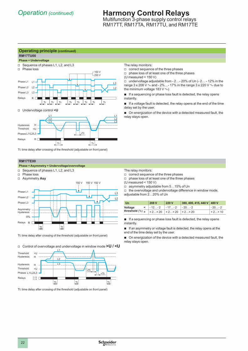
Operating principle (continued)RM17TU00Phase + Undervoltage v Sequence of phases L1, L2, and L3 v Phase loss
R
L3
L2
L1 L3
L2
Tr Tr Tr Tr Tr Tr Tr Tr
150 V 250 V
Phase L3
Phase L2
Phase L1
Relays
v Undervoltage control <U
L1/L2/L3
L1L2L3
L2L1
L3
TrR
<UH
<Tr
Tr
ThresholdHysteresis
Relays
Phases
The relay monitors: v correct sequence of the three phases v phase loss of at least one of the three phases
(U measured < 150 V) v undervoltage adjustable from - 2…- 20% of Un (- 2… - 12% in the
range 3 x 208 V a and - 2%…- 17% in the range 3 x 220 V a due to the minimum voltage 183 V a)
b If a sequencing or phase loss fault is detected, the relay opens instantly.
b If a voltage fault is detected, the relay opens at the end of the time delay set by the user.
b On energization of the device with a detected measured fault, the relay stays open.
Tt: time delay after crossing of the threshold (adjustable on front panel)
RM17TE00Phase + Asymmetry + Undervoltage/overvoltage v Sequence of phases L1, L2, and L3 v Phase loss v Asymmetry Asy
L2
L3
0%
Tt TtR
150 V 150 V150 V
Phase L3
Phase L2
Phase L1
HysteresisAsymmetry
Relays
The relay monitors: v correct sequence of the three phases v phase loss of at least one of the three phases
(U measured < 150 V) v asymmetry adjustable from 5…15% of Un v the overvoltage and undervoltage difference in window mode,
adjustable from 2…20% of Un
Un 208 V 220 V 380, 400, 415, 440 V 480 VVoltage threshold (%)
< - 12…- 2 - 17…- 2 - 20…- 2 - 20…- 2> + 2…+ 20 + 2…+ 20 + 2…+ 20 + 2…+ 10
b If a sequencing or phase loss fault is detected, the relay opens instantly.
b If an asymmetry or voltage fault is detected, the relay opens at the end of the time delay set by the user.
b On energization of the device with a detected measured fault, the relay stays open.
Tt: time delay after crossing of the threshold (adjustable on front panel)
v Control of overvoltage and undervoltage in window mode >U / <U
L1/L2/L3
L1
L2
L3
Tt Tt Tt
11-1211-14
>UH
H<U <Tt
<Tt
Threshold
Hysteresis
Hysteresis
Threshold
Relays
Tt: time delay after crossing of the threshold (adjustable on front panel)
Phases
23
References Harmony Control RelaysMultifunction 3-phase supply control relaysRM17TT, RM17TA, RM17TU, and RM17TE
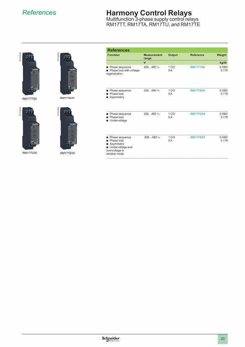
ReferencesFunction Measurement
range Output Reference Weight
V kg/lb b Phase sequence b Phase loss with voltage
regeneration
208…480 a 1 CO5 A
RM17TT00 0.080/ 0.176
b Phase sequence b Phase loss b Asymmetry
208…480 a 1 CO5 A
RM17TA00 0.080/ 0.176
b Phase sequence b Phase loss b Undervoltage
208…480 a 1 CO5 A
RM17TU00 0.080/ 0.176
b Phase sequence b Phase loss b Asymmetry b Undervoltage and
overvoltage in window mode
208…480 a 1 CO5 A
RM17TE00 0.080/ 0.176
RM17TT00
PF15
3402
A
RM17TU00
PF15
3404
A
RM17TA00
PF15
3404
A
RM17TE00
PF15
3405
A
Presentation, description, operation
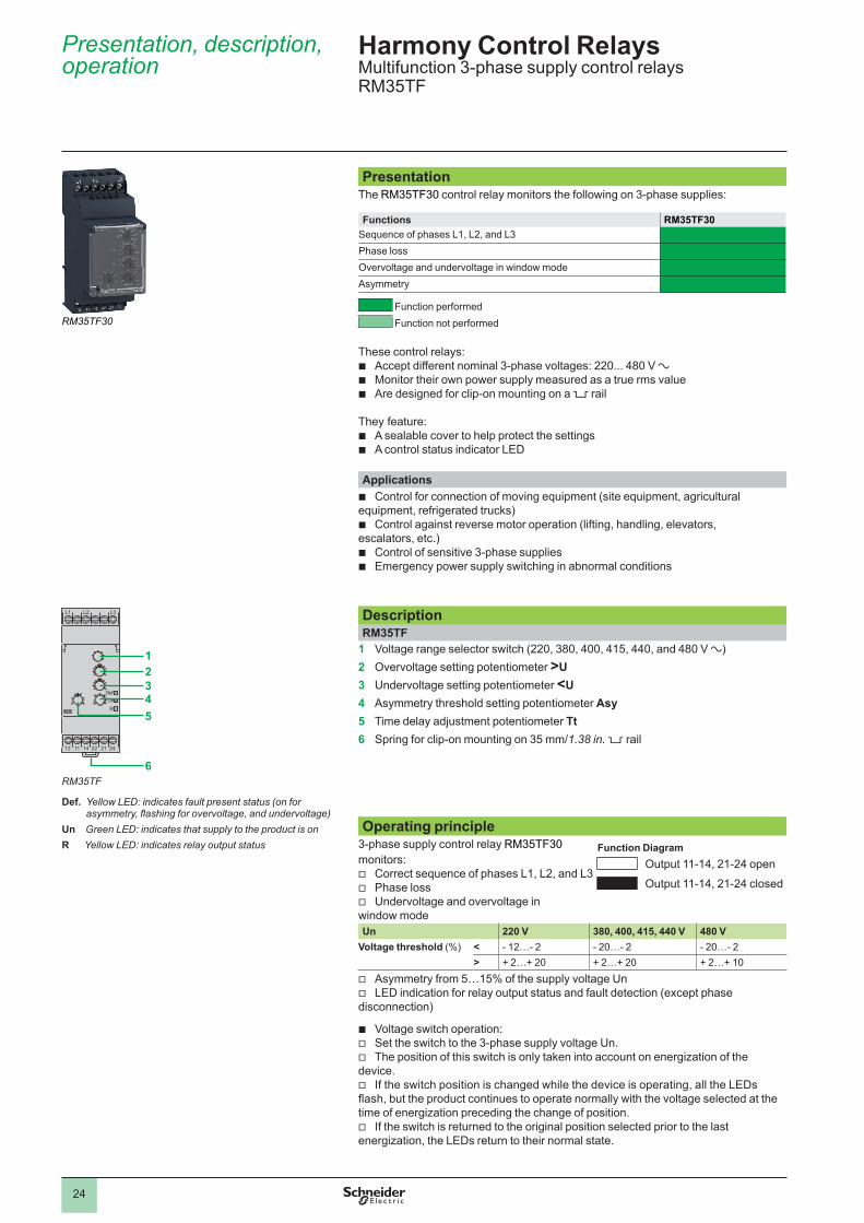
PresentationThe RM35TF30 control relay monitors the following on 3-phase supplies:
Functions RM35TF30Sequence of phases L1, L2, and L3Phase lossOvervoltage and undervoltage in window modeAsymmetry
Function performed Function not performed
These control relays:
b Accept different nominal 3-phase voltages: 220... 480 V a b Monitor their own power supply measured as a true rms value b Are designed for clip-on mounting on a 5 rail
They feature: b A sealable cover to help protect the settings b A control status indicator LED
Applications b Control for connection of moving equipment (site equipment, agricultural
equipment, refrigerated trucks) b Control against reverse motor operation (lifting, handling, elevators,
escalators, etc.) b Control of sensitive 3-phase supplies b Emergency power supply switching in abnormal conditions
DescriptionRM35TF
1 Voltage range selector switch (220, 380, 400, 415, 440, and 480 V a)2 Overvoltage setting potentiometer >U3 Undervoltage setting potentiometer <U4 Asymmetry threshold setting potentiometer Asy5 Time delay adjustment potentiometer Tt6 Spring for clip-on mounting on 35 mm/1.38 in. 5 rail
Operating principle3-phase supply control relay RM35TF30 monitors:
v Correct sequence of phases L1, L2, and L3 v Phase loss v Undervoltage and overvoltage in
window mode
Function DiagramOutput 11-14, 21-24 openOutput 11-14, 21-24 closed
Un 220 V 380, 400, 415, 440 V 480 VVoltage threshold (%) < - 12…- 2 - 20…- 2 - 20…- 2
> + 2…+ 20 + 2…+ 20 + 2…+ 10 v Asymmetry from 5…15% of the supply voltage Un v LED indication for relay output status and fault detection (except phase
disconnection)
b Voltage switch operation: v Set the switch to the 3-phase supply voltage Un. v The position of this switch is only taken into account on energization of the
device. v If the switch position is changed while the device is operating, all the LEDs
flash, but the product continues to operate normally with the voltage selected at the time of energization preceding the change of position.
v If the switch is returned to the original position selected prior to the last energization, the LEDs return to their normal state.
Harmony Control RelaysMultifunction 3-phase supply control relays RM35TF
4.1
RM35TF30
L1
12 22 21 2411 14
L3L2
Def.UnR
12345
6
Def. Yellow LED: indicates fault present status (on for asymmetry, flashing for overvoltage, and undervoltage)
Un Green LED: indicates that supply to the product is onR Yellow LED: indicates relay output status
RM35TF
24

Operation (continued),references
Harmony Control RelaysMultifunction 3-phase supply control relays RM35TF
Operating principle (continued)RM35TFPhase + Overvoltage + Undervoltage in window mode v Sequence of phases L1, L2, and L3 v Phase loss v Asymmetry
R
L3
150 V150 V150 V
0%
Tt Tt
Phase L3
Phase L2
HysteresisAsymmetry
Relay
Phase L1
The relay monitors: v correct sequence of the three phases v phase loss of at least one of the three phases
(U measured < 150 V) v asymmetry, adjustable from 5 to 15% of Un v the undervoltage, adjustable from - 2…- 20% of Un (- 2…- 12% in
the range 3 x 220 V a) v the overvoltage, adjustable from + 2…+ 20% of Un (+ 2…+ 10% in
the range 3 x 480 V a due to the maximum voltage 528 V a) b If a sequencing or phase loss fault is detected, the relay opens
instantly. b If an asymmetry or voltage fault is detected, the relay opens at the
end of the time delay set by the user. b On energization of the device with a detected measured fault, the
relay stays open.
Note: Tt: time delay after crossing of the threshold (adjustable on front panel)
v Control of overvoltage and undervoltage in window mode <U< L1
L2
L3
Tt Tt TtR
<UH
H>U
L1/L2/L3<Tt
<TtThreshold
Hysteresis
Hysteresis
Threshold
Relay
ReferenceFunction Rated 3-phase
supply voltage Output Reference Weight
V kg/lbb Phase sequenceb Phase lossb Asymmetryb Undervoltage and
overvoltage in window mode
220…480 a 2 CO 5 A RM35TF30 0.130/ 0.287
RM35TF30
PF15
3428
A
Phase
25
2
1
3
4
5
6
7
8
9
10
2
1
3
4
5
6
7
8
9
10
28603-ENversion: 5

26
Presentation, description
Presentation Voltage measurement and control relays RM35UB330, RM17UB310 and RM35UB3N30 monitor the following, on 3-phase supplies:Functions RM35UB330 RM17UB310 RM35UB3N30
Phase lossAbsence of neutralOvervoltage and undervoltageVoltage between phases 220…480 V a 208…480 V aVoltage between phases and neutral
120…277 V a
Function performedFunction not performed
Depending on the model, control relays: b Monitor their own power supply measured as a true rms value b Are designed for clip-on mounting on a 5 rail
They feature: b A sealable cover to help protect the settings b A control status indicator LED
Applications b Control for connection of moving equipment (site equipment, agricultural
equipment, refrigerated trucks) b Control against reverse motor operation (lifting, handling, elevators,
escalators, etc.) b Control of sensitive 3-phase supplies b Emergency power supply switching in abnormal conditions
DescriptionRM35UB330, RM35UB3N30
1a Voltage range selector switch (220, 380, 400, 415, 440, and 480 V a)1b Voltage range selector switch (120, 127, 220, 230, 240, 260, and 277 V a) 2 Overvoltage setting potentiometer >U3 Undervoltage setting potentiometer <U4 Undervoltage threshold delay setting potentiometer Tt25 Overvoltage threshold delay setting potentiometer Tt16 Spring for clip-on mounting on 35 mm/1.38 in. 5 rail
RM17UB3101 Voltage range selector switch (208, 220, 380, 400, 415, 440, and 480 V a)2 Time delay adjustment potentiometer Tt3 Overvoltage setting potentiometer >U4 Undervoltage setting potentiometer <U5 Spring for clip-on mounting on 35 mm/1.38 in. 5 rail
Harmony Control Relays3-phase voltage control relays RM17UB3 and RM35UB3
RM17UB310RM35UB3ppp
L1
12 22 21 2411 14
L3L2
R1Un
R2
1a23
5
6
4
L1
12 22 21 2411 14
L3 NL2
R1Un
R2
1b23
5
6
4
L1 L2 L3
12 11 14
123
5
4
Un Green LED: indicates that supply to the product is onR1 Yellow LED: indicates relay output status. Overvoltage thresholdR2 Yellow LED: indicates relay output status. Undervoltage threshold
Un Green LED: indicates that supply to the product is onR Yellow LED: indicates relay output status
RM35UB330 RM35UB3N30
RM17UB310

27
Operation
Operating principle3-phase voltage control relays monitor:
b Undervoltage and overvoltage:Function Diagram
Output 11-14, 21-24 openOutput 11-14, 21-24 closed
Un Phase/phase 208 V 220 V 380, 400, 415, 440 V 480 VRM17UB310 > U (%) + 2…+ 20 + 2…+ 20 + 2…+ 20 + 2…+ 10
< U (%) - 12…- 2 - 17…- 2 - 20…- 2 - 20…- 2RM35UB30 > U (%) – + 2…+ 20 + 2…+ 20 + 2…+ 10
< U (%) – - 12…- 2 - 20…- 2 - 20…- 2
Un Phase/neutral 120 V 127 V 220, 230, 240, 260 V 277 VRM35UB3N30 > U (%) + 2…+ 20 + 2…+ 20 + 2…+ 20 + 2…+ 20
< U (%) - 20…- 2 - 20…- 2 - 20…- 2 - 20…- 2
b Phase loss b Presence of neutral (RM35UB3N30 only)
b Measurements are made between Phases for RM35UB330 and RM17UB310 and between Phase/Neutral for RM35UB3N30 b Fault signaling is by LED b RM35UB relays can differentiate between the source of the fault (one LED for overvoltage threshold, one LED for undervoltage threshold)
b Voltage switch operation: v Set the switch to the 3-phase supply voltage Un. v The position of this switch is only taken into account on energization of the device. v If the switch position is changed while the device is operating, all the LEDs flash, but the product continues to operate normally with the
voltage selected at the time of energization preceding the change of position. v If the switch is returned to the original position selected prior to the last energization, the LEDs return to their normal state.
RM35UB330Overvoltage/undervoltage control v Phase loss
150 V 150 V150 V
Phase L3
Phase L2
Phase L1
Relays R1/R2
b The relay monitors: v phase loss (U measured < 150 V) v the undervoltage v the overvoltage
b Each threshold has its own independently adjustable time delay from 0.3 to 30 s.
b If a voltage fault is detected, the corresponding relay (one undervoltage output/one overvoltage output) opens at the end of the time delay set by the user.
b If a phase loss is detected, both relays open instantly without waiting for the end of the time delay set by the user.
b On energization of the device with a detected measured fault, the relays stay open.
Note: Tt 1: overvoltage threshold delay (adjustable on front panel) Tt 2: undervoltage threshold delay (adjustable on front panel)
v Overvoltage and undervoltage
>UH
H<U
L1/L2/L311-1211-14
21-2221-24
L1L2
L3
Tt1 Tt2
<Tt1<Tt2Phases
Relay R1
Relay R2
Hysteresis
Hysteresis
Harmony Control Relays3-phase voltage control relaysRM17UB3 and RM35UB3
Threshold
Threshold

28
Operation (continued)
Operating principle (continued)RM35UB3N30Overvoltage/undervoltage + absence of neutral control v Phase loss
80 V 80 V80 V
Phase L3
Phase L2
Phase L1
Relays R
b The relay monitors: v presence of the neutral v the undervoltage v the overvoltage v phase loss (U measured < 80 V) b Each threshold has its own independently adjustable time delay from
0.3 to 30 s. b If a voltage fault is detected, the corresponding relay (one
undervoltage output/one overvoltage output) opens at the end of the time delay set by the user.
b In the absence of either neutral or phase, both relays open instantly without waiting for the end of the time delay set by the user.
b On energization of the device with a detected measured fault, the relays stay open.
Note: Tt 1: overvoltage threshold delay (adjustable on front panel) Tt 2: undervoltage threshold delay (adjustable on front panel)
v Overvoltage and undervoltage
>UH
H<U
L1/L2/L3
L1L2
L3
Tt1 Tt2
11-1211-14
21-2221-24
<Tt1<Tt2Phases
Relay R1
Relay R2
Hysteresis
Hysteresis
RM17UB310Overvoltage/undervoltage control v Phase loss
150 V 150 V 150 V
Phase L3
Phase L2
Phase L1
Relays R
b The relay monitors: v the undervoltage v the overvoltage v phase loss (U measured < 150 V) b An adjustable time delay from 0.3 to 30 s allows inhibition of the
output relay if a transient fault occurs. b If a voltage fault is detected, the relay opens at the end of the time
delay set by the user. b On energization of the device with a detected measured fault, the relay
stays open. b If phase loss is detected, the relay opens instantly.
Note: Tt: overvoltage and undervoltage threshold delay (adjustable on front panel)
v Overvoltage and undervoltage
11-12/11-14
L1L2
L3
Tt Tt
<U
>U
Phases L1/L2/L3
Relays R
Hysteresis
Hysteresis
Harmony Control Relays3-phase voltage control relaysRM17UB3 and RM35UB3
Threshold
Threshold

29
References
ReferencesFunction Measurement
rangeOutput Reference Weight
V kg/lbb Overvoltage and
undervoltage between phases
220…480 a(Phase-phase)
1 CO +1 CO1 per threshold5 A
RM35UB330 0.130/ 0.287
208…480 a(Phase-phase)
1 CO5 A
RM17UB310 0.080/ 0.176
b Overvoltage and undervoltage between phases and neutral
b Absence of neutral
120…277 a(Phase-neutral)
1 CO +1 CO1 per threshold5 A
RM35UB3N30 0.130/ 0.287
Harmony Control Relays3-phase voltage control relays RM17UB3 and RM35UB3
RM35UB330
RM35UB3N30
RM17UB310
PF15
3428
APF
1534
28A
PF15
3405
A
Presentation, description
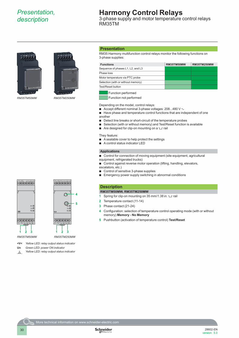
PresentationRM35 Harmony multifunction control relays monitor the following functions on 3-phase supplies:
Functions RM35TM50MW RM35TM250MWSequence of phases L1, L2, and L3Phase lossMotor temperature via PTC probeSelection (with or without memory)Test/Reset button
Function performed Function not performed
Depending on the model, control relays: b Accept different nominal 3-phase voltages: 208...480 V a b Have phase and temperature control functions that are independent of one
another b Detect line breaks or short-circuit of the temperature probes b Selection (with or without memory) and Test/Reset function is available b Are designed for clip-on mounting on a 5 rail
They feature: b A sealable cover to help protect the settings b A control status indicator LED
Applications b Control for connection of moving equipment (site equipment, agricultural
equipment, refrigerated trucks) b Control against reverse motor operation (lifting, handling, elevators,
escalators, etc.) b Control of sensitive 3-phase supplies b Emergency power supply switching in abnormal conditions
DescriptionRM35TM50MW, RM35TM250MW
1 Spring for clip-on mounting on 35 mm/1.38 in. 5 rail2 Temperature contact (11-14)3 Phase contact (21-24)4 Configuration: selection of temperature control operating mode (with or without
memory) Memory - No Memory5 Pushbutton (activation of temperature control) Test/Reset
Harmony Control Relays3-phase supply and motor temperature control relays RM35TM
4.0
RM35TM50MW RM35TM250MW
T1 L1 L2 L3
A1 1411 21 24A2
T2
UnR2
R1
1 2 3
T1 L1 L2 L3
A1 1411 21 24A2
T2 Y1
UnR2
R1
1 2 3
4
5
RM35TM50MW RM35TM250MW
<V< Yellow LED: relay output status indicatorUn Green LED: power ON indicator
L1
L2L3Yellow LED: relay output status indicator
30
2
1
3
4
5
6
7
8
9
10
2
1
3
4
5
6
7
8
9
10
28602-ENversion: 5.0

Operation
Operating principleRelays RM35TM50MW and RM35TM250MW monitor:
b Status of the 3-phase supply b Temperature of motors with embedded PTC probes
The 3-phase supply control function monitors: b Correct sequence of phases L1, L2, and L3 b Phase loss
Function DiagramPower supply offPower supply onOutput 11-14, 21-24 openOutput 11-14, 21-24 closed
RM35TM50MW/RM35TM250MW3-phase supply control v Sequence of phases L1, L2, and L3 v Phase loss
21-24
100 V 100 V100 V
L3
L2
Phase L1
Phase L2
Phase L3Phase relay R2
b As soon as phase sequence (L1, L2, and L3) and phase presence are considered to be correct, the output relay contact closes and LED R2 is lit.
b If total failure or drop in amplitude of a phase (U measured < 100 V) or inversion of phase sequence is detected, the output relay contact opens and LED R2 goes out.
b The result of the control is indicated by the status of output relay R2, NO contact 21-24 is open in the event of a fault.
Temperature controlv Motor temperature control via PTC probe
1650 W3100 W
15 W
Supply Un
Resistance T1-T2
Temperature relay R1
b The temperature control relay can take up to 6 PTC (positive temperature coefficient) probes wired in series between terminals T1 and T2.
b A fault is declared when the resistance of the temperature sensing circuit exceeds 3100 Ω.
b Return to normal status is detected when the resistance is once again below 1650 Ω.
b The result of the control is indicated by the status of the “temperature” output relay, NO contact 11-14 is open in the event of a fault.
b Opening of the thermal sensing circuit, which has the same effect as a high temperature (resistance exceeds 3100 Ω), is therefore interpreted as a fault.
b Total short-circuiting of the temperature probe(s), detected when resistance is less than 15 Ω ± 5 Ω, is treated as a fault.
b LED R1 is on when the temperature is correct.
Harmony Control Relays3-phase supply and motor temperature control relaysRM35TM
3100 Ω
1650 Ω
15 Ω
31

Operation (continued)
Operating principle (continued)RM35TM250MWConfiguration
This configuration is considered when relay RM35TM250MW is energized.
b Set the switch to the required operating mode: v Temperature control without memory v Temperature control with memory b On energization, placing the switch in one of the five intermediate positions holds the relay in the open contact state and the detected error
is signaled by simultaneous flashing of the LEDs. b The position of the mode selector switch is taken into account on energization. b Any modification of its position during operation has no effect - the active configuration may therefore be different from that indicated by the
switch - the RM35TM250MW operates normally but the change in configuration is signaled by simultaneous flashing of the three LEDs.
Motor temperature control via PTC probe with memory v Memory
S2 T1/Y1
1650
R T1-T2
3100
15
Test/Reset
Un
Reset
11-12
Supply
Temperature relay R1
b Relay RM35TM250MW has a selector switch which allows the temperature control operating mode to be configured with or without memory.
b In “memory” mode, when a fault is detected, the “temperature” relay locks in the open position.
b As soon as the temperature returns to the correct value, the relay can be unlocked (reset), either by pressing the “Test/Reset” button (for at least 200 ms), or by closing a volt-free contact (for at least 200 ms) between terminal Y1 and T1 (without a parallel load).
b Relay RM35TM250MW can also be reset by switching off the power (see reset time).
Use of “Test/Reset” button v No Memory
15 Ω
1650 Ω3100 Ω
Test/Reset
Test/Reset
Supply Un
Resistance T1-T2
Temperature relay R1
b Relay version RM35TM250MW has a “Test/Reset” button which can be used to check that the temperature control function is working correctly and to reset this function after locking in “memory” mode.
b The press and release times are 50 ms for both functions. b When the temperature is normal, pressing the “Test/Reset” button simulates
overheating, the “temperature” output relay contact is open and the <V< LED is off. b If “memory” mode is not active, “fault” indication is maintained for as long as the
button is pressed. b If “memory” mode is active, “fault” indication is locked and the button needs to be
released and pressed again to reset the function. b In “memory” mode, when a fault has been detected and the temperature has
returned to normal, the “temperature” control relay can be unlocked (reset) by pressing the “Test/Reset” button.
v MemoryReset Reset Reset
15 Ω
1650 Ω3100 Ω
Test/Reset
Supply Un
Resistance T1-T2
Temperature relay R1
Harmony Control Relays3-phase supply and motor temperature control relaysRM35TM
Resistance
32

References
ReferencesFunction Supply
voltageMeasurement range
Output Reference Weight
V V kg/lbb Phase sequenceb Phase lossb Motor temperature
via PTC probe
24…240 z 208…480 a 2 NO5 A
RM35TM50MW 0.120/ 0.264
b Phase sequenceb Phase lossb Motor temperature
via PTC probeb Selection (with or
without memory)b “Test/Reset” button
24…240 z 208…480 a 2 NO5 A
RM35TM250MW 0.120/ 0.264
Harmony Control Relays3-phase supply and motor temperature control relaysRM35TM
RM35TM50MW
PF15
6413
A
RM35TM250MW
PF15
6414
A
33

34
RM17UAS15315M
Presentation, description
Harmony Control Relays1-phase voltage control relaysRM17UAS and RM17UBE
Presentation 1-phase voltage measurement and control relays RM17UASpp and RM17UBEppmonitor:Functions RM17
UAS14RM17 UAS15
RM17UA S15315M
RM17 UAS16
RM17 UBE15
RM17 UBE16
UndervoltageOvervoltage or undervoltageOvervoltage and undervoltage in window mode (with/without memory)Ranges controlled 9…15 c 65…260 z Fixed at
165 a20…80 z 65…260 z 20…80 z
Function performedFunction not performed
Depending on the model, control relays: b Allow selection of operating mode b Monitor their own power supply measured as a true rms value b Are designed for clip-on mounting on a 5 rail
They feature: b A sealable cover to help protect the settings b A control status indicator LED
Applications b Protection of electronic or electromechanical devices against overvoltage
and undervoltage b Emergency power supply switching at abnormal conditions b Anti short-cycle for compressor used in HVAC machinery
DescriptionRM17UASpp (except RM17UAS15315M)
1 Configuration: selection of operating mode <U / >U, Memory - No Memory2 Setting potentiometer3 Hysteresis adjustment potentiometer H4 Time delay setting potentiometer Tt5 Spring for clip-on mounting on 35 mm/1.38 in. 5 rail
RM17UAS15315M1 Time delay setting potentiometer Tt2 Spring for clip-on mounting on 35 mm/1.38 in. 5 rail
RM17UBE1p
1 Maximum voltage range selection and setting potentiometer2 Minimum voltage range selection and setting potentiometer3 Time delay setting potentiometer Tt4 Spring for clip-on mounting on 35 mm/1.38 in. 5 rail
RM17UBEpp
A1 A2
12 11 14
R
<U >U
Un
123
5
4
12 11 14
R
Un
A1 A2
1
1
2
2
3
4
Un Green LED: indicates that supply to the product is onR Yellow LED: indicates relay output status
Un Green LED: indicates that supply to the product is onR Yellow LED: indicates relay output status
Un Green LED: indicates that supply to the product is onR Yellow LED: indicates relay output status
RM17UASpp (except RM17UAS15315M)
RM17UBE1p
RM17UAS15315M
A1 A2
12 11 14
R
Un
Tt
3
5
79
11
13
15min
5.0

35
Operation
Operating principleVoltage control relays RM17UAS (except RM17UAS15315M) and RM17UBE monitor:
b Voltage of 1-phase and DC supplies b RM17UASpp relays support two operating modes: v Overvoltage or undervoltage v Fault memory selected or not b An adjustable time delay, on crossing the thresholds,
provides immunity to transients, and helps prevent spurious triggering of the output relay
b Fault signaling is by LED
Function DiagramPower supply offPower supply onOutput 11-14, 21-24 openOutput 11-14, 21-24 closed
RM17 UAS14/UAS15/UAS16 (except RM17UAS15315M)The operating mode is determined by a switch:
b Undervoltage with or without memory b Overvoltage with or without memory
The position of the configuration switch and the operating mode is read by the product on energization: b If the configuration switch is set to an unacceptable position, the product detects a fault, the output relay stays open and the LEDs flash to
indicate the position error. b If the switch position is changed while the device is operating, all the LEDs flash, but the product continues to operate normally with the
function selected at the time of energization preceding the change of position. b If the configuration switch is returned to the original position selected prior to the last energization, the LEDs return to their normal state.
The undervoltage or overvoltage threshold value is set by a graduated potentiometer clearly indicating the voltage Un to be monitored. The hysteresis is adjusted by a potentiometer graduated from 5…20% of the threshold setting. The hysteresis value must not exceed the limit values of the measuring range.
Undervoltage/Overvoltage without memory
v Undervoltage control <U, No Memory Un
Tt
<Tt
UH<U
11-1211-14
Relays R
Hysteresis
Supply
Threshold
If the controlled voltage falls below the threshold setting for a time greater than that set on the front panel (0.1…10 s), the output relay opens and the R LED goes off. As soon as the voltage returns to a value above (or below) the threshold setting minus (or respectively plus) the hysteresis, the relay instantly closes.
v Overvoltage control >U, No Memory
U
Un
>UH
Tt
<Tt11-1211-14
Relays R
Threshold
Supply
Hysteresis
If the controlled voltage exceeds the threshold setting for a time greater than that set on the front panel (0.1…10 s), the output relay opens and the R LED goes off. As soon as the voltage returns to a value below the threshold setting plus the hysteresis, the relay instantly closes.
Harmony Control Relays1-phase voltage control relaysRM17UAS and RM17UBE

36
Operation (continued)
Operating principle (continued)RM17 UAS14/UAS15/UAS16 (except RM17UAS15315M) (continued)Undervoltage/Overvoltage with memory
v Undervoltage control <U, Memory
Tt11-12/11-14
U
<U
Relays R
Hysteresis
Supply Un
Threshold
If “Memory” mode is selected, the relay opens when crossing of the threshold is detected and then stays in that position. The power needs to be switched off to reset the product.
v Overvoltage control >U, Memory
11-12/11-14
>U
U
Tt
Relays R
Threshold
Supply Un
Hysteresis
Note: Tt: time delay after crossing of the threshold
RM17 UBE15/UBE16Overvoltage + undervoltage control in window mode
>U
Tt Tt
U<U11-12/11-14Relays R
Hysteresis
Supply Un
ThresholdHysteresis
Threshold
These relays operate in window mode where they check that the controlled voltage stays between a minimum threshold and a maximum threshold.
b The undervoltage or overvoltage threshold values are set by two graduated potentiometers clearly indicating the voltage Un to be monitored. The hysteresis is fixed at 3% of the threshold setting.
b If the controlled voltage exceeds the high threshold setting, or falls below the low threshold setting for a time greater than that set on the front panel (0.1…10 s), the output relay opens and the R LED goes out. During the time delay, this LED flashes.
b As soon as the voltage falls below the high threshold setting value minus the hysteresis, or rises above the low threshold setting value plus the hysteresis, the relay instantly closes.
b On energization of the device with a detected measured fault, the relay stays open.
Note: Tt: time delay after crossing of the threshold
RM17UAS15315MUndervoltage
If the controlled voltage falls below the threshold (165 V a), the output relay instantly opens and the R LED goes out. As soon as the voltage returns to a value above the threshold plus the hysteresis, the relay closes after the time set on the front panel (3…15 min).
Note: Tt: time delay after crossing of the threshold
Harmony Control Relays1-phase voltage control relaysRM17UAS and RM17UBE
220 V a
HysteresisThreshold
Relays RTt
<UU
>U
U
<U
UnSupply
Tt

37
References
References1-phase voltage control relaysFunction Ranges
controlledTime delay Output Reference Weight
V s kg/lb b Overvoltage
or undervoltage (with/without memory)
9…15 c Off delay 0.1...10
1 CO5 A
RM17UAS14 0.080/ 0.176
20…80 z Off delay 0.1...10
1 CO5 A
RM17UAS16 0.080/ 0.176
65…260 z Off delay 0.1...10
1 CO5 A
RM17UAS15 0.080/ 0.176
b Overvoltage and undervoltage in window mode (without memory)
20…80 z Off delay 0.1...10
1 CO5 A
RM17UBE16 0.080/ 0.176
65…260 z Off delay 0.1...10
1 CO5 A
RM17UBE15 0.080/ 0.176
1-phase voltage control relays, 220 V a rated supply voltageFunction Ranges
controlledTime delay Output Reference Weight
V min kg/lb b Undervoltage
(without memory)Fixed at 165 a On delay
3...151 CO5 A
RM17UAS15315M 0.080/0.176
Harmony Control Relays1-phase voltage control relaysRM17UAS and RM17UBE
RM17UBE16
RM17UAS15315M
RM17UBE15
PF15
3411
ASS
R_C
P190
09_1
PF15
3411
A

38
Harmony Control RelaysMultifunction 1-phase voltage control relaysRM35UA
Presentation, description, operation
RM35UA1pMW
Presentation Multifunction voltage control relays RM35UA1pMW monitor both AC and DC voltages.Functions RM35UA11MW RM35UA12MW RM35UA13MW
Overvoltage or undervoltage (with or without memory)Range controlled 0.05…5 V 1…100 V 15…600 V
Function performedFunction not performed
Depending on the model, the control relays allow: b Automatic c or a recognition b Measurement ranges from 0.05 V to 600 V b Selection between overvoltage and undervoltage b Measurement as a true rms value b Selectable memory function b Clip-on mounting on a 5 rail
They feature: b A sealable cover to help protect the settings b A control status indicator LED
Applications b DC motor overspeed control b Battery monitoring b Monitoring of AC or DC supplies b Speed monitoring (with tacho-generator)
DescriptionRM35 UA11MW/UA12MW/UA13MW
1 Configuration: selection of operating mode <U / >U, (with or without memory) Memory - No Memory
2 Voltage threshold setting potentiometer U Value3 Hysteresis adjustment potentiometer H4 Time delay setting potentiometer Tt5 Spring for clip-on mounting on 35 mm/1.38 in. 5 rail
Operating principleMultifunction voltage relays RM35UA1pMW:
b Automatically recognize the form of c or a (50 or 60 Hz) signal
b Fault signaling is by LED
Function DiagramPower supply offPower supply onOutput 11-14, 21-24 openOutput 11-14, 21-24 closed
RM35 UA11MW/UA12MW/UA13MWThe operating mode is selected by using a switch:
b Undervoltage with or without memory b Overvoltage with or without memory
The position of the switch and the operating mode is read by the product on energization:
b If the switch is set to an unacceptable position, the product detects a fault, the output relay stays open and the LEDs flash to indicate the position error.
b If the switch position is changed while the device is operating, all the LEDs flash, but the product continues to operate normally with the function selected at the time of energization preceding the change of position.
b If the configuration switch is returned to the original position selected prior to the last energization, the LEDs return to their normal state.
The undervoltage or overvoltage threshold value is set by a potentiometer graduated as a percentage of the scale value of Un to be monitored. The hysteresis is adjusted by a potentiometer graduated from 5…50% of the threshold setting. The hysteresis value must not exceed the limit values of the measuring range.
A1
12 22 21 241411
A2 E3 E2 E1 M
Un
R
< U > U
123
4
5
Un Green LED: indicates that supply to the product is onR Yellow LED: indicates relay output status
RM35 UA11MW/UA12MW/UA13MW

39
Harmony Control RelaysMultifunction 1-phase voltage control relaysRM35UA
Operation (continued),references
Operating principle (continued)RM35 UA11MW/UA12MW/UA13MWOvervoltage/undervoltage without memory
b Overvoltage control > U, without memoryUn
>U
UH
Tt
<Tt11-12/11-1421-22/21-24
Relays R
Hysteresis
Supply
Threshold
If the voltage controlled exceeds the threshold setting for a time greater than that set on the front panel (0.3…30 s), the output relay opens and the R LED goes off. During the time delay, this LED flashes. As soon as the voltage drops below the value of the threshold setting, minus the hysteresis, the relay instantly closes.
Note: Tt: time delay after crossing of the threshold (adjustable on front panel)
b Undervoltage control < U, without memory
<Tt11-12/11-1421-22/21-24
U
Tt
<UH
Un
Relays R
Hysteresis
Supply
Threshold
If the voltage controlled falls below the threshold setting for a time greater than that set on the front panel (0.3…30 s), the output relay opens and the R LED goes off. During the time delay, this LED flashes. As soon as the voltage rises above the value of the threshold setting plus the hysteresis, the relay instantly closes.
Note: Tt: time delay after crossing of the threshold (adjustable on front panel)
Overvoltage/undervoltage with memory
b Overvoltage control > U, with memory
11-12/11-1421-22/21-24
U >
U
Tt
Relays R
Hysteresis
Supply Un
Threshold
If “Memory” mode is selected, the relay opens when crossing of the threshold is detected and then stays in that position. The power needs to be switched off to reset the product.
Note: Tt: time delay after crossing of the threshold (adjustable on front panel)
b Undervoltage control < U, with memory
11-12/11-1421-22/21-24
U
Tt
U <
Relays R
Hysteresis
Supply Un
Threshold
ReferencesFunction Range
controlledSupply voltage
Output Reference Weight
V V kg/lb b Overvoltage
or undervoltage (with/without memory)
0.05…5 z 24…240 z 2 CO 5 A
RM35UA11MW 0.130/ 0.287
1…100 z 24…240 z 2 CO 5 A
RM35UA12MW 0.130/ 0.287
15…600 z 24…240 z 2 CO 5 A
RM35UA13MW 0.130/ 0.287
RM35UA13MWRM35UA11MW RM35UA12MW
PF15
3418
A
PF15
3418
A
PF15
3418
A
>U
<U
U
U
U

40
PresentationRM22UA and RM22UB 1-phase or DC voltage control relays monitor the following functions:Functions RM22 UA2MR UA3MR UA33MT UB34
Overvoltage (without memory)Overvoltage or undervoltage (with/without memory)Overvoltage and undervoltage (window mode)
Function performedFunction not performed
RM22 control relays allow: b Automatic AC or DC recognitionb Selection between overvoltage and undervoltageb Monitoring of their own supply voltage measured as a true rms valueb Selectable memory functionb Clip-on mounting on a 5 rail
They feature a:b Dial pointer LED indicator for relay power ON statusb Relay output status LEDb A sealable cover to help protect the settings b A control status indicator LED
Applicationsb Protection of electronic or electromechanical devices against overvoltage and undervoltageb Emergency power supply switching in abnormal conditionsb DC motor overspeed controlb Monitoring of AC or DC suppliesb Battery and speed monitoring (with tacho-generator)
DescriptionRM22UA2MR, RM22UA3MR, RM22UA33MT, RM22UB34
1 Configuration: selection of operating mode <U (undervoltage), >U (overvoltage), >U> (overvoltage and undervoltage), MEMORY - NO MEMORY (with or without memory)
2a Voltage threshold setting potentiometer U value2b Undervoltage setting potentiometer <U2c Overvoltage setting potentiometer >U3 Time delay adjustment potentiometer Tt4a Hysteresis adjustment potentiometer Hys4b Hysteresis/overvoltage and undervoltage window mode adjustment
potentiometer Hys/>U>5 Diagnostic button6 Configuration: selection of On-delay or Off-delay
Presentation, description
Harmony Control Relays1-phase voltage control relaysRM22UA and RM22UB
RM22UA31MRRM22UA21MR
A1 A2 M
12 11 14
22 21 24
R
Hys
RM22UA23MR
DIAGNOSTIC
E1 E2 E3
>UValue
5
1015
20 3540 45
50%
10
2030
40 7080 90
100% 2c4a
5
RM22UA2pMR
A1 A2 M
12 11 14
E1 E2 E3
22 21 24
U
>
MEM
OR
Y
NO
>
MEM
OR
Y
R
UValue
Hys/>U>
Tt
U >
>
> U
RM22UA31MR
U< U>
< U
DIAGNOSTIC
5
1015
20 3540 45
50%
10
2030
40 7080 90
100%
0,1 30s
5
10 20
25
12a4b35
RM22UA3pMR
A1+ A2-
12 11 14
22 21 24
ON
OFF
DEL
AY
100120140
160 220240260
300V
R
>U
<U
Tt
RM22UB34
DIAGNOSTIC
80280
0,1 30s
5
10 20
25
DEL
AY
100120140
160 220240260
300V80280 2b
2c6
35
RM22UB34
A1 A2 M
12 11 14
E1 E2 E3
22 21 24
R
RM22UA33MT
DIAGNOSTIC
U
>
MEM
OR
Y
NO
>
MEM
OR
Y
10
2030
40 708090
100%
5
1015
20 354045
50%
UValue
Hys/>U>
Tt
U >
>
> U
U< U> U<
0,1 30s
5
10 20
25
12a4b35
RM22UA33MT
R Yellow LED: indicates relay output status

41
Operation
Operating principle1-phase voltage control relays monitor:
b the voltage of 1-phase and DC supplies b their own supply voltage for the RM22UB model
An adjustable time delay on threshold crossing, provides immunity to transients, and helps prevent spurious triggering of the output relay.
Function DiagramPower supply offPower supply onOutput 11-14, 21-24 openOutput 11-14, 21-24 closed
RM22 UA2MR/UA3MR/UA33MTThe operating mode is determined by the user:
b Undervoltage with or without memory b Overvoltage with or without memory
The position of the configuration switch and the operating mode is read by the product on energization: b If the configuration switch is set to an unacceptable position, the product detects a fault, the output relay stays open, and the LEDs flash to
indicate the position error. b If the configuration switch position is changed while the device is operating, all the LEDs flash, but the product continues to operate
normally with the function selected at the time of energization preceding the position change. b If the configuration switch is returned to the original position selected prior to the last energization, the LEDs return to their normal state.
The undervoltage or overvoltage threshold value is set by means of a potentiometer graduated as a percentage of the scale value of U to be monitored. The hysteresis is adjusted by means of a potentiometer graduated from 5…50% of the threshold setting. The hysteresis value must not exceed the limit values of the measuring range.
Overvoltage without memory b Overvoltage control > U, without memory
>U
Tt <Tt
URRelay
outputs
Hysteresis
Supply Un
Threshold
If the controlled voltage exceeds the threshold setting for a time greater than that set on the front panel (0.1…30 s), the output relay opens and the R LED goes off. During the time delay, this LED flashes.As soon as the voltage drops below the value of the threshold setting minus the hysteresis, the relay instantly closes.
Undervoltage without memory b Undervoltage control < U, without memory
U
<U
TtR
<Tt
Relay outputs
Hysteresis
Supply Un
Threshold
If the controlled voltage falls below the threshold setting for a time greater than that set on the front panel (0.1…30 s), the output relay opens and the R LED goes off. During the time delay, this LED flashes.As soon as the voltage rises above the value of the threshold setting plus thehysteresis, the relay instantly closes.
Harmony Control Relays1-phase voltage control relaysRM22UA and RM22UB

42
Operation (continued) Harmony Control Relays1-phase voltage control relaysRM22UA and RM22UB
Operating principle (continued)RM22 UA2MR/UA3MR/UA33MT (continued)Overvoltage/undervoltage with memory v Overvoltage control > U, with memory
>U
U
TtR
Relay outputs
Hysteresis
Supply Un
Threshold
If “Memory” mode is selected, the relay opens when crossing of the threshold is detected and then stays in that position. The power has to be switched off to reset the product.
Note: Tt: time delay after crossing of the threshold
v Undervoltage control < U, with memory
U
Tt
<U
RRelay outputs
Hysteresis
Supply Un
Threshold
RM22 UA3MR/UA33MT/UB34Overvoltage + undervoltage control relay in window mode b Overvoltage and undervoltage control
in window mode <U<
Tt Tt
U
>U
<U
RRelay outputs
Hysteresis
Supply Un
ThresholdHysteresis
Threshold
These relays operate in window mode where they check that the controlled voltage stays between a minimum and a maximum threshold.
b The undervoltage or overvoltage threshold values are set by means of two graduated potentiometers clearly indicating the Un to be monitored. The hysteresis is fixed at 5% of the threshold setting.
b If the controlled voltage exceeds the high threshold setting or falls below the low threshold setting for a time greater than that set on the front panel (0.1…30 s), the output relay opens and the R LED goes off. During the time delay, this LED flashes.
b As soon as the voltage falls below the high threshold setting value minus the hysteresis, or rises above the low threshold setting value plus the hysteresis, the relay instantly closes.
b On energization of the device with a detected measured fault, the relay stays open.
If “Memory” mode is selected, the relay opens when crossing of the threshold is detected and then stays in that position. The power has to be switched off to reset the product.
Note: Tt: time delay after crossing of the threshold

43
References
ReferencesFunction Rated supply
voltageMeasurement range
Time delay Output Reference Weight
V V kg/lbb Overvoltage
(without memory)24…240 z 0.05…5 z No 2 CO 8 A RM22UA21MR 0.110/
0.242
24…240 z 1…100 z No 2 CO 8 A RM22UA22MR 0.110/ 0.242
24…240 z 15…500 z No 2 CO 8 A RM22UA23MR 0.110/ 0.242
b Overvoltage or undervoltage (with/without memory)
b Overvoltage and undervoltage in window mode (with/without memory)
24…240 z 0.05…5 z Off delay (0.1...30 s)
2 CO 8 A RM22UA31MR 0.110/ 0.242
24…240 z 1…100 z Off delay (0.1...30 s)
2 CO 8 A RM22UA32MR 0.110/ 0.242
24…240 z 15…500 z Off delay (0.1...30 s)
2 CO 8 A RM22UA33MR 0.110/ 0.242
380…415 a 15…500 a Off delay (0.1...30 s)
2 CO 8 A RM22UA33MT 0.110/ 0.242
b Overvoltage and undervoltage in window mode (without memory)
110…240 z 80…300 z On/Off delay (0.1...30 s)
2 CO 8 A RM22UB34 0.090/ 0.198
Harmony Control Relays1-phase voltage control relaysRM22UA and RM22UB
RM22UA33MT
RM22UA23MR RM22UA33MR
RM22UB34
PF14
3409
PF14
3413
PF14
3412
PF14
3414

44
Harmony Control Relays1-phase current control relays with integratedcurrent transformerRM17JC
Presentation, description
Presentation The control relay RM17JC00MW is designed to monitor a currents.Functions RM17JC00MW
Overcurrent (without memory)
Function performedFunction not performed
These control relays allow: b Integrated current transformer b Measurement range 2…20 A b Choice of action on the output relay b Clip-on mounting on a 5 rail
They feature a control status indicator LED.
Applications b Load state control of motors and generators b Control of current drawn by a 3-phase motor b Monitoring of heating or lighting circuits b Control of pump draining (undercurrent) b Control of overtorque (crushers) b Monitoring of electromagnetic brakes or clutches
DescriptionRM17JC00MW
1 Overcurrent setting potentiometer2 Spring for clip-on mounting on 35 mm/1.38 in. 5 rail
RM17JC00MW
2
A1 Y1 A2
12 11 14
Un
R 1
Un Green LED: indicates that supply to the product is onR Yellow LED: indicates relay output status
RM17JC00MW
2
1
3
4
5
6
7
8
9
10
2
1
3
4
5
6
7
8
9
10
28607-ENversion: 5.0
4.0

45
Harmony Control Relays1-phase current control relays with integratedcurrent transformerRM17JC
Operation, references
Operating principleControl relay RM17JC00MW is:
b equipped with an integrated current transformer b fault signaling is by LED
Function DiagramPower supply offPower supply on
RM17JC00MWOvercurrent detection
Overcurrent detection > I
I>
I
Y1 A1
Y1 A1 11-1211-14
11-1211-14
Relays R
Relays R
Hysteresis
Supply Un
b Relay RM17JC00MW controls overcurrent. b The relay closes when the current exceeds the threshold setting on the front
panel and opens when it drops below the threshold minus the hysteresis. b When terminal Y1 is linked to A1 (+), the output is reversed. The relay opens
when the current exceeds the threshold setting on the front panel and closes again when it drops below the hystereris value.
ReferenceFunction Supply Measurement
rangeOutput Reference Weight
V A kg/lb b Overcurrent
(without memory)24…240 z 2…20 1 CO
5 ARM17JC00MW 0.110/
0.243
RM17JC00MW
PF15
3412
A
I >I

46
PresentationRM22JA and RM35JA multifunction current control relays monitor the following functions:
Functions RM22JA21MR RM22JA31MR RM35JA 32MR/32MTOvercurrent (without memory)
Overcurrent (with/without memory)
Undercurrent (with/without memory)
Overcurrent and undercurrent (with/without memory) (window mode)
Function performedFunction not performed
These control relays enable: b Automatic a or c recognitionb Selection between overcurrent and undercurrentb Measurement as a true rms valueb Selectable memory functionb Clip-on mounting on a 5 rail
They feature:b Dial pointer LED indicator for relay power ON statusb Relay output status LEDb A sealable cover to help protect the settings b A control status indicator LED
Applicationsb Excitation control of DC machinesb Load state control of motors and generatorsb Control of current drawn by a 3-phase motorb Monitoring of heating or lighting circuitsb Control of pump draining (undercurrent)b Control of overtorque (crushers)b Monitoring of electromagnetic brakes or clutches DescriptionRM22JA21MR, RM22JA31MR, RM35JA32MR, RM35JA32MT
1 Configuration: selection of operating mode <I (undercurrent), >I (overcurrent), >I> (overcurrent and undercurrent), MEMORY - NO MEMORY (with or without memory)
2 Current threshold setting potentiometer I%3a Hysteresis adjustment potentiometer Hys3b Hysteresis/overcurrent and undercurrent window mode adjustment
potentiometer Hys/>I>4 Time delay adjustment potentiometer Tt5 Diagnostic button6 Overcurrent setting potentiometer >I
Presentation, description
Harmony Control Relays1-phase current control relays RM22JA and RM35JA
RM35JA32MTRM22JA21MR
A1 A2 M
12 11 14
22 21 24
5
1015
20 3540 45
50%
R
Hys
RM22JA21MR
DIAGNOSTIC
10
20
3040 70
80
90
100%
E1 E2 E3
% I I I>
3a6
RM22JA21MR
MEM
OR
Y
NO
MEM
OR
Y
10
2030
40 708090
100%
5
1015
20 354045
50%
0,1 30s
5
10 20
25
A1 A2 M
12 11 14
E1 E2 E3
22 21 24
> >
R
Hys/
Tt
>
>
>
RM22JA31MR
<><
DIAGNOSTIC
% I I I
I I I> >
I I
I
I I
I
I I
I
I I
I
I I
I
I I
I
3b21
45
RM22JA31MR
A1 A2 E3 E2 E1 M
12 11 14 22 21 24
RM35JA32MR
R
DIAGNOSTIC
<
>
> >MEMORY
> >
>
<
Hys/
Tt
100%10
20
30
40 70
80
90
50%5
10
15
20 35
40
45
30s0,1
5
10 20
25
% I I I
I I I> >
I I I
I I I
I I I
I I I
I I I I I
I
YES NO
3b21
45
RM35JA32MR
<
>
> >MEMORY
> >
>
<
Hys/
Tt
100%10
20
30
40 70
80
90
50%5
10
15
20 35
40
45
30s0,1
5
10 20
25
A1 A2 E3 E2 E1 M
12 11 14 22 21 24
RM35JA32MT
R
DIAGNOSTIC
% I I I
I I I> >
I I I
I I I
I I I
I I I
I I I I I
I
YES NO
3b21
45
RM35JA32MT
R Yellow LED: indicates relay output status

47
Operation
Operating principleCurrent control relays monitor the current of 1-phase and DC supplies.
An adjustable time delay on threshold crossing provides immunity to transients, helping prevent spurious triggering of the output relay.
Function DiagramPower supply offPower supply onOutput 11-14, 21-24 openOutput 11-14, 21-24 closed
RM22JA1MR/RM35JA32MThe operating mode is determined by the user:
b Undercurrent with or without memory b Overcurrent with or without memory
The position of the configuration switch and the operating mode is read by the product on energization: b If the configuration switch is set to an unacceptable position, the product detects a fault, the output relay stays open and the LEDs flash to
indicate the position error. b If the configuration switch position is changed while the device is operating, all the LEDs flash, but the product continues to operate normally
with the function selected at the time of energization preceding the change of position. b If the configuration switch is returned to the original position selected prior to the last energization, the LEDs return to their normal state.
The undercurrent or overcurrent threshold value is set by means of a potentiometer graduated as a percentage of the scale value of I to be monitored. The hysteresis is adjusted by means of a potentiometer graduated from 5…50% of the threshold setting. The hysteresis value must not exceed the limit values of the measuring range.
Overcurrent/Undercurrent without memory
v Overcurrent detection >I , without memory
Tt <Tt
>II
Relay outputs
Hysteresis
Supply Un
Threshold
If the controlled current exceeds the threshold setting for a time greater than that set on the front panel (0.1…30 s), the output relay opens and the R LED goes off. During the time delay, this LED flashes.As soon as the current drops below the value of the threshold setting minus the hysteresis, the relay instantly closes.
v Undercurrent detection <I, without memory
Tt Tt
<II
Relay outputs
Hysteresis
Supply Un
Threshold
If the controlled current falls below the threshold setting for a time greater than that set on the front panel (0.1…30 s), the output relay opens and the R LED goes off. During the time delay, this LED flashes.As soon as the current rises above the value of the threshold setting plus the hys-teresis, the relay instantly closes.
Note: Tt: time delay after crossing of the threshold
Harmony Control Relays1-phase current control relays RM22JA and RM35JA
R
R

48
Operation (continued) Harmony Control Relays1-phase current control relaysRM22JA and RM35JA
Operating principle (continued)RM22JA1MR/RM35JA32M (continued)Overcurrent/Undercurrent with memory
v Overcurrent >I, with memory
Tt Tt
>I
I
Relay outputs
Hysteresis
Supply Un
Threshold
v Undercurrent <I, with memory
If “Memory” mode is selected, the relay opens when threshold crossing is detected and then stays in that position. The power has to be switched off to reset the product.
Tt Tt
<I I
Relay outputs
Hysteresis
Supply Un
ThresholdNote: Tt: time delay after crossing of the threshold
RM22JA1MR/RM35JA32MOvercurrent and undercurrent control in window mode v Overcurrent and undercurrent control in
window mode <I<, without memory
Supply Un
ThresholdHysteresis
HysteresisThreshold
>I
<I
Relay outputs Tt
<TtU<Tt
TtR
These relays operate in window mode where they check that the controlled current stays between a minimum and a maximum threshold.
b The undercurrent or overcurrent threshold values are set by means of two graduated potentiometers clearly indicating the I to be monitored. The hysteresis is fixed at 5% of the threshold setting.
b If the controlled current exceeds the high threshold setting or falls below the low threshold setting for a time greater than that set on the front panel (0.1…30 s), the output relay opens and the R LED goes off. During the time delay, this LED flashes.
b As soon as the current falls below the high threshold setting value minus the hysteresis, or rises above the low threshold setting value plus the hysteresis, the relay instantly closes.
b On energization of the device with a detected measured fault, the relay stays open.
Note:Tt: time delay after crossing of the threshold
R
R
> I
< I
> I
< I

49
References
ReferencesFunction Rated
supply voltage
Measurement range
Time delay
Output Reference Weight
V kg/lbb Overcurrent
(without memory)24…240 z 4 mA…1 A z No 2 CO 8 A RM22JA21MR 0.110/
0.242
b Overcurrent (with/without memory)
b Undercurrent (with/without memory)
b Overcurrent and undercurrent in window mode (with/without memory)
24…240 z 4 mA…1 A z Off delay (0.1...30 s)
2 CO 8 A RM22JA31MR 0.110/ 0.242
24…240 z 150 mA…15 A z Off delay (0.1...30 s)
2 CO 8 A RM35JA32MR 0.120/ 0.264
380…415 a 150 mA…15 A z Off delay (0.1...30 s)
2 CO 8 A RM35JA32MT 0.120/ 0.264
Harmony Control Relays1-phase current control relaysRM22JA and RM35JA
RM35JA32MR
RM22JA21MR RM22JA31MR
RM35JA32MT
PF14
3415
PF14
3416
PF14
3418
PF14
3417

50
Presentation, description, operation
Harmony Control Relays1-phase current control relaysRM35JA
Presentation Multifunction current control relays RM35JA3pMW monitor both AC and DC currents.Functions RM35JA31MW RM35JA32MW
Overcurrent (with/without memory)Undercurrent (with/without memory)Range controlled 2 …500 mA 0.15…15 A
Function performed
Function not performed
These control relays allow: b Automatic AC or DC recognition b Measurement ranges from 2 mA to 15 A b Selection between overcurrent and undercurrent b Measurement as a true rms value b Selectable memory function b Clip-on mounting on a 5 rail
They feature: b A sealable cover to help protect the settings b A control status indicator LED
Applications b Excitation control of DC machines b Control of the load state of motors and generators b Control of current drawn by a 3-phase motor b Monitoring of heating or lighting circuits b Control of pump draining (undercurrent) b Control of overtorque (crushers) b Monitoring of electromagnetic brakes or clutches
DescriptionRM35JA31MW, RM35JA32MW
1 Configuration: selection of operating mode <I / >I, (with or without memory) Memory - No Memory
2 Current threshold setting potentiometer I%3 Hysteresis adjustment potentiometer Hysteresis4 Time delay adjustment potentiometer Tt5 Starting inhibition time delay adjustment potentiometer Ti6 Spring for clip-on mounting on 35 mm/1.38 in. 5 rail
Operating principleControl relays RM35JA3pMW are designed to:
b monitor a or c currents b automatically recognize the form of
c or a (50 or 60 Hz) signal b directly monitor up to 15 A (above this
value a current transformer can be connected)
b signal detected faults by means of LEDs
Function DiagramPower supply offPower supply onOutput 11-14, 21-24 openOutput 11-14, 21-24 closed
RM35JA3pMW
A1
12 22 21 241411
A2 E3 E2 E1 M
< I > I
UnR
123
6
4
Un Green LED: indicates that supply to the product is onR Yellow LED: indicates relay output status
RM35JA31MW, RM35JA32MW
5

51
Operation (continued), references
Harmony Control Relays1-phase current control relaysRM35JA
Operating principle (continued)RM35 JA31MW/JA32MW
The operating mode is selected by a switch: b Undercurrent, with or without memory b Overcurrent, with or without memory
The position of the switch and the operating mode is read by the product on energization: b If the switch is set to an unacceptable position, the product detects a fault, the output relay stays open and the LEDs flash to indicate the
position error. b If the switch position is changed while the device is operating, all the LEDs flash, but the product continues to operate normally with the
function selected at the time of energization preceding the change of position. b If the configuration switch is returned to the original position selected prior to the last energization, the LEDs return to their normal state.
The undercurrent or overcurrent threshold value is set by a potentiometer graduated as a percentage of the scale value of current I to be monitored. The hysteresis is adjusted by a potentiometer graduated from 5…50% of the threshold setting and the value must not exceed the limit values of the measuring range.Overcurrent/Undercurrent without memory
b Overcurrent detection >I, without memory If the current controlled exceeds the threshold setting for a time greater than that set on the front panel (0.3…30 s), the output relay opens and the LED goes off. As soon as the current drops below the value of the threshold setting minus the hysteresis, the relay instantly closes.
11-12/11-1421-22/21-24
Tt Tt TiTi
I
I >
Relays R
Hysteresis
Supply
Threshold
b Undercurrent detection < I, without memory If the current controlled falls below the threshold setting for a time greater than that set on the front panel (0.3…30 s), the output relay opens and the LED goes off. As soon as the current rises above the value of the threshold setting plus the hysteresis, the relay instantly closes.
11-12/11-1421-22/21-24
TiTt Tt Ti
II <
Relays R
Hysteresis
Supply Un
Threshold
Overcurrent/Undercurrent with memory
b Overcurrent detection >I, with memory If “Memory” mode is selected, the relay opens when crossing of the threshold is detected and then stays in that position. The power needs to be switched off to reset the product.
On energization, an inhibition time delay (1…20 s) makes it possible to inhibit current peaks (or troughs) on start-up of equipment.
11-12/11-1421-22/21-24
Ti Tt Ti
II >
Tt
Relays R
Hysteresis
Supply Un
Threshold
b Undercurrent detection < I, with memory
11-12/11-1421-22/21-24
Ti Ti
II <
Tt Tt
Relays R
Hysteresis
Supply Un
Threshold
Note: Ti: starting inhibition time (adjustable on front panel) Tt: time delay after crossing of the threshold (adjustable on front panel)
ReferencesFunction Range
controlledSupply Output Reference Weight
V kg/lb
b Overcurrent or undercurrent (with/without memory)
2 …500 mA 24…240 z 2 CO 5 A
RM35JA31MW 0.130/ 0.286
0.15…15 A 24…240 z 2 CO 5 A
RM35JA32MW 0.130/ 0.286
RM35JA31MW
PF15
3420
B
RM35JA32MW
PF15
3420
B
> I
< I
< I
> I
<I

52
PresentationRM22LA and RM22LG liquid level control relays control one or two liquid levels, with a fill or empty function: Functions RM22LA 32MR RM22LG 11MR/11MT
Level 1/Level 2Fill operationEmpty operationLow sensitivityStandard sensitivityHigh sensitivity
Function performedFunction not performed
RM22 liquid level control relays feature:b A dial pointer LED indicator for relay power ON statusb A relay output status LED b A sealable cover to help protect the settings b A control status indicator LED
The relays are designed for clip-on mounting on a 5 rail.
ApplicationsThese devices monitor the levels of conductive liquids.They control the actuation of pumps or valves to regulate levels and can also help prevent submersible pumps “dry running”, or tanks “overflowing”. They can also be used to control dosing of liquids in mixing processes and to help protect heating elements in the event of non-immersion.They have a transparent, hinged cover on their front panel to avoid any accidental alteration of the settings. This cover can be directly sealed.
b Application examples for compatible liquids:v spring, town, industrial, and sea waterv metallic salt, acid, or base solutionsv liquid fertilizersv non-concentrated alcohol (< 40%)v liquids in the food processing industry: beer, coffee, etc.
DescriptionRM22LG11MR, RM22LG11MT, RM22LA32MR
1 Configuration: selection of the operating mode (Fill or Empty) and the sensitivity range (LS/St/HS)
2 Sensitivity control potentiometer (kΩ or %)3 Configuration: selection of the number of levels and the On/Off time delay4 Time delay control potentiometer Tt5 Diagnostic button
Presentation, description
Harmony Control RelaysLiquid level control relays RM22LA and RM22LG
RM22LG11MR
A1 A2 NC
12 11 14
22 21 24
R
Sens
Level
Tt
RM22LA32MR
DIAGNOSTIC
Min Max C
St. St. HS
LS
LS
HS
1
2
1
2
102030 70
80
100%590
40 60
ON
D
ELAY
OFF
DEL
AY
0,1 30s
5
10 20
25
321
45
RM22LA32MR
A1 A2 NC
12 11 14
102030 70
80
100
R
Sens
Level
RM22LG11MR
DIAGNOSTIC
590
Min Max C
40 60
1 2
KΩ
321
5
RM22LG11MR
A1 A2 NC
12 11 14
R
Sens
Level
RM22LG11MT
DIAGNOSTIC
Min Max C
102030 70
80
100590
40 60
1 2
KΩ
321
5
RM22LG11MT
R Yellow LED: indicates relay output status

53
Operation
Operating principleLiquid level control relays are designed to measure and control the levels of conductive liquids by means of resistive probes.The operating principle is based on measurement of the apparent resistance of the liquid between two submerged probes. When this value is less than the threshold setting on the front panel of the device, the relay changes state. To avoid electrolytic phenomena, an AC current runs across the probes. A selector switch on the front panel allows selection of the required function and the sensitivity range. Control of a single level can be achieved by using the second se-lector switch. In this case, the Max. level probe stays up in the air and an adjustable time delay avoids any wave effect. Both products activate their output relay when a tank is either emptying or filling.
Function DiagramPower supply OffPower supply OnOutput 11-14, 21-24 openOutput 11-14, 21-24 closed
RM22LA and RM22LGA selector switch on the front panel of these relays allows selection of the required sensitivity range and the empty or fill function. A second switch allows selection of the number of levels (1 or 2) and the type of time delay in the case of level 1 mode. The position of these configuration switches is taken into account on energization.b If the configuration switch is set to an unacceptable position, the product detects a fault, the output relay stays open, and the LEDs flash to signal the position error. b If the configuration switch position is changed while the device is operating, all the LEDs flash, but the product continues to operate normally with the function selected at the time of energization preceding the change of position.b If the configuration switch is returned to the original position selected prior to the last energization, the LEDs return to their normal state.
Control of two levels, empty and fill function v Fill/Empty function (2 levels)
R
R
Supply Un
Relay outputs
Relay outputs
Max. level
Min. level
b Empty functionlevel: 2, function:
- LS (Low Sensitivity: 250 W…5 kW)- St (Standard Sensitivity: 5 kW…100 kW)- HS (High Sensitivity: 50 kW…1 MW)
The output relay stays open until the liquid reaches the Max. level probe. As soon as the Max. level is reached, the contact closes and then allows emptying of the tank (valve opens, pump starts, etc.). When the level drops below the Min. level, the contact opens to stop the emptying process.
b Fill functionlevel: 2, function:
- LS (Low Sensitivity: 250 W…5 kW)- St (Standard Sensitivity: 5 kW…100 kW)- HS (High Sensitivity: 50 kW…1 MW)
The output relay stays energized until the liquid reaches the Max. level probe. As soon as the Max. level is reached, the contact opens and the pump stops. When the level drops below the Min. level, the contact closes again and pumping restarts to raise the level.
Harmony Control RelaysLiquid level control relays RM22LA and RM22LG

54
Operation (continued) Harmony Control RelaysLiquid level control relays RM22LA and RM22LG
Operating principle (continued)RM22LA and RM22LG (continued) Control of one level, empty function v Empty function T on
Tt <Tt Tt Tt
Un
(1)
11-12/11-14
Supply
Relay outputs
Level
b Level: 1 - on delay functions:- LS (Low Sensitivity: 250 W…5 kW)- St (Standard Sensitivity: 5 kW…100 kW)- HS (High Sensitivity: 50 kW…1 MW)
When the liquid level rises above the probe for a time greater than the time delay value Tt set on the front panel, the relay is energized and stays energized until the liquid level drops back to the probe. If the liquid drops back below the set level before the end of the time delay, the relay is not energized.
v Empty function T off
Tt Tt<Tt Tt
Un
(1)
11-12/11-14
Supply
Relay outputs
Level
b Level: 1 - off delay functions: - LS (Low Sensitivity: 250 W…5 kW)- St (Standard Sensitivity: 5 kW…100 kW)- HS (High Sensitivity: 50 kW…1 MW)
When the liquid level rises above the probe, the relay is energized instantly and stays energized until the liquid again reaches the probe level for a time Tt set on the front panel. If the liquid drops back below the set level before the end of the time delay period, the relay stays energized.
Control of one level, fill function v Fill function T on
Tt <Tt Tt Tt
Un
(1)
11-12/11-14
Supply
Relay outputs
Level
b Level: 1 - on delay functions:- LS (Low Sensitivity: 250 W…5 kW)- St (Standard Sensitivity: 5 kW…100 kW)- HS (High Sensitivity: 50 kW…1 MW)
When the liquid level drops below the probe for a time greater than the time delay value Tt set on the front panel, the relay is energized and stays energized until the liquid level rises back up to the probe. If the liquid rises back above the set level before the end of the time delay period, the relay is not energized.
v Fill function T off
Tt <Tt Tt Tt
Un
(1)
11-12/11-14
Supply
Relay outputs
Level
b Level: 1 - off delay functions: - LS (Low Sensitivity: 250 W…5 kW)- St (Standard Sensitivity: 5 kW…100 kW)- HS (High Sensitivity: 50 kW…1 MW)
When the liquid level drops below the probe, the relay is energized instantly and stays energized until the liquid level again reaches the probe level and stays above it for a time greater than the time delay period Tt set on the front panel. If the liquid drops back below the set level before the end of the time delay period, the relay stays energized.
Note: Tt: time delay after crossing of the threshold

55
References Harmony Control RelaysLiquid level control relays RM22LA and RM22LG
ReferencesFunction Rated supply
voltageMeasurement range
Time delay
Output Reference Weight
V Ω kg/lbb Level 1/
Level 2b Fill
operationb Empty
operation
24…240 z 5 K…100 K No 1 CO 8 A RM22LG11MR 0.100/ 0.220
380…415 a 5 K…100 K No 1 CO 8 A RM22LG11MT 0.100/ 0.220
24…240 z 250...1 M On/Off delay (0.1...30 s)
2 CO 8 A RM22LA32MR 0.110/ 0.242
RM22LA32MR
RM22LG11MR RM22LG11MT
PF14
3419
PF14
3421
PF14
3420
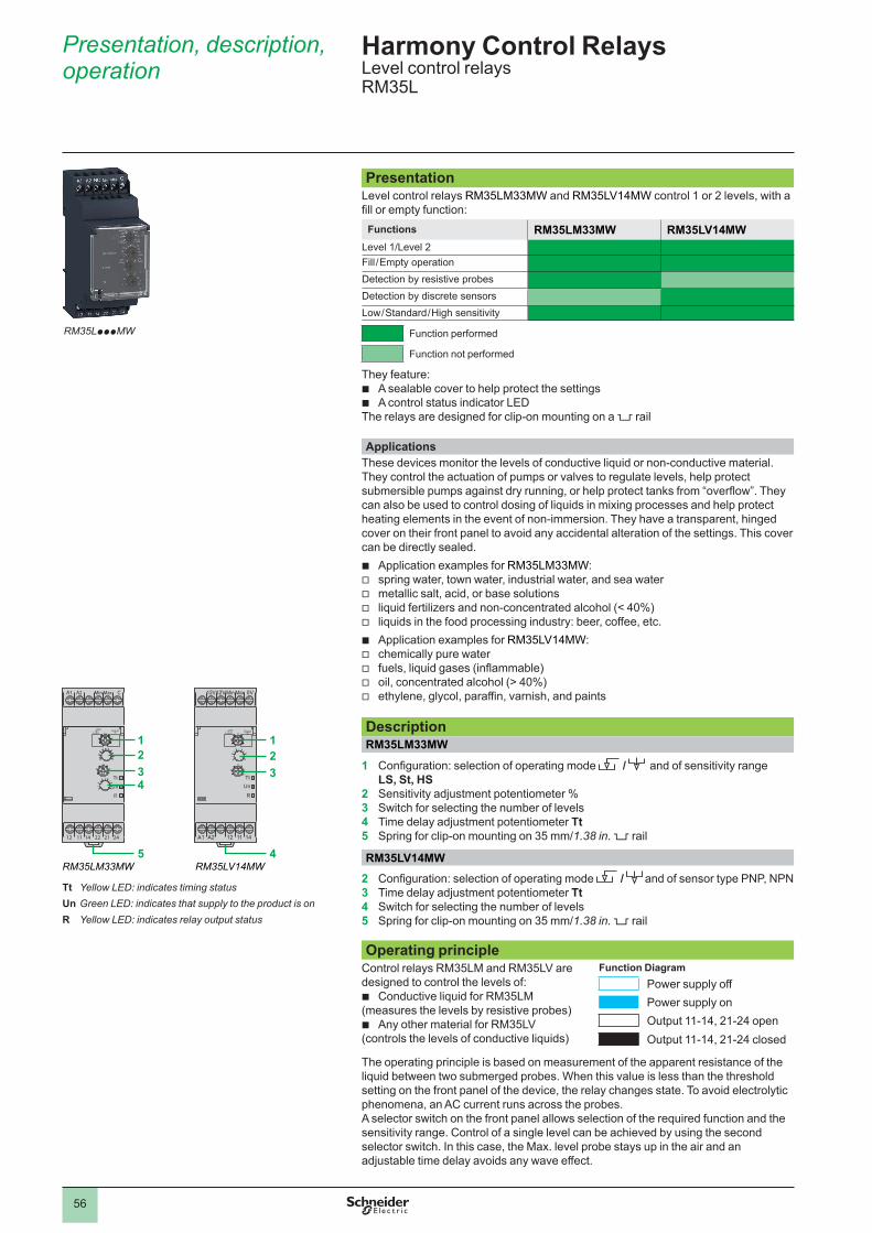
56
Presentation, description, operation
Harmony Control Relays Level control relays RM35L
RM35LpppMW
Presentation Level control relays RM35LM33MW and RM35LV14MW control 1 or 2 levels, with a fill or empty function:
Functions RM35LM33MW RM35LV14MWLevel 1/Level 2Fill / Empty operationDetection by resistive probesDetection by discrete sensorsLow / Standard / High sensitivity
Function performed
Function not performed
They feature: b A sealable cover to help protect the settings b A control status indicator LED
The relays are designed for clip-on mounting on a 5 rail
ApplicationsThese devices monitor the levels of conductive liquid or non-conductive material.They control the actuation of pumps or valves to regulate levels, help protect submersible pumps against dry running, or help protect tanks from “overflow”. They can also be used to control dosing of liquids in mixing processes and help protect heating elements in the event of non-immersion. They have a transparent, hinged cover on their front panel to avoid any accidental alteration of the settings. This cover can be directly sealed.
b Application examples for RM35LM33MW: v spring water, town water, industrial water, and sea water v metallic salt, acid, or base solutions v liquid fertilizers and non-concentrated alcohol (< 40%) v liquids in the food processing industry: beer, coffee, etc. b Application examples for RM35LV14MW: v chemically pure water v fuels, liquid gases (inflammable) v oil, concentrated alcohol (> 40%) v ethylene, glycol, paraffin, varnish, and paints
DescriptionRM35LM33MW
1 Configuration: selection of operating mode / and of sensitivity range LS, St, HS
2 Sensitivity adjustment potentiometer %3 Switch for selecting the number of levels4 Time delay adjustment potentiometer Tt5 Spring for clip-on mounting on 35 mm/1.38 in. 5 rail
RM35LV14MW2 Configuration: selection of operating mode / and of sensor type PNP, NPN3 Time delay adjustment potentiometer Tt 4 Switch for selecting the number of levels5 Spring for clip-on mounting on 35 mm/1.38 in. 5 rail
Operating principleControl relays RM35LM and RM35LV are designed to control the levels of:
b Conductive liquid for RM35LM (measures the levels by resistive probes)
b Any other material for RM35LV (controls the levels of conductive liquids)
Function DiagramPower supply offPower supply onOutput 11-14, 21-24 openOutput 11-14, 21-24 closed
The operating principle is based on measurement of the apparent resistance of the liquid between two submerged probes. When this value is less than the thresholdsetting on the front panel of the device, the relay changes state. To avoid electrolytic phenomena, an AC current runs across the probes.A selector switch on the front panel allows selection of the required function and the sensitivity range. Control of a single level can be achieved by using the second selector switch. In this case, the Max. level probe stays up in the air and an adjustable time delay avoids any wave effect.
A1
12 22 21 2411 14
A2 Min Max C
Tt
Un
R
123
5
4
12V
A1 12 11 14A2
12V Min Max 0V
TtUn
R
123
4
Tt Yellow LED: indicates timing statusUn Green LED: indicates that supply to the product is onR Yellow LED: indicates relay output status
RM35LM33MW RM35LV14MW

57
Operation (continued)
Operating principleRM35LM33MW
Relay RM35LV measures the levels by means of discrete sensors. These two products activate their output relay when a tank is either emptying or filling.
b A green Un LED indicates that the supply is on. b A yellow R LED indicates the state of the output relay. b A yellow Tt LED indicates that timing is in progress. b The green and yellow LEDs flash to indicate an unacceptable setting position.
A selector switch on the front panel of these relays allows selection of the required sensitivity range and the empty or fill function. A second switch allows selection of the number of levels (1 or 2) and the type of time delay in the case of level 1 mode.
The position of these configuration switches is taken into account on energization. b If the configuration switch is set to an unacceptable position, the product detects a fault, the output relay stays open, and the LEDs flash to
signal the position error. b If the configuration switch position is changed while the device is operating, all the LEDs flash, but the product continues to operate normally
with the function selected at the time of energization preceding the change of position. b If the configuration switch is returned to the original position selected prior to the last energization, the LEDs return to their normal state.
Control of two levels, empty and fill function v Fill/Empty function
R
R
Supply Un
Relays
Relays
Max. level
Min. level
b Empty functionlevel: 2, function:
- LS (Low Sensitivity: 250 W…5 kW) - St (Standard Sensitivity: 5 kW…100 kW) - HS (High Sensitivity: 50 kW…1 MW)
The output relay stays open until the liquid reaches the Max. level probe. As soon as the Max. level is reached, the contact closes and allows emptying of the tank (valve opens, pump starts, etc.). When the level drops below the Min. level, the contact opens to stop the emptying process.
b Fill functionlevel: 2, function:
- LS (Low Sensitivity: 250 W…5 kW) - St (Standard Sensitivity: 5 kW…100 kW) - HS (High Sensitivity: 50 kW…1 MW)
The output relay stays energized until the liquid reaches the Max. level probe. As soon as the Max. level is reached, the contact opens and the pump stops. When the level drops below the Min. level, the contact closes again and pumping re-starts to raise the level.
Note: When two levels are being controlled, the anti-wave time delay function is not active.
Control of one level, empty function v Empty function T on
Tt <Tt Tt Tt
Un
(1)
11-12/11-1421-22/21-24
Supply
Relays R
Level
b Level: 1 - on delay functions: - LS (Low Sensitivity: 250 W…5 kW) - St (Standard Sensitivity: 5 kW…100 kW) - HS (High Sensitivity: 50 kW…1 MW)
When the liquid level rises above the probe for a time greater than the time delay value Tt set on the front panel, the relay is energized and stays energized until the liquid level drops back to the probe. If the liquid drops back below the set level before the end of the time delay, the relay is not energized.
v Empty function T off
Tt
Un
(1)
<Tt Tt Tt
11-12/11-1421-22/21-24
Supply
Relays R
Level
b Level: 1 - off delay functions: - LS (Low Sensitivity: 250 W…5 kW) - St (Standard Sensitivity: 5 kW…100 kW) - HS (High Sensitivity: 50 kW…1 MW)
When the liquid level rises above the probe, the relay is energized instantly and stays energized until the liquid again reaches the probe level for a time Tt set on the front panel. If the liquid drops back below the set level before the end of the time delay period, the relay stays energized.
Harmony Control Relays Level control relays RM35L

58
Operation (continued) Harmony Control Relays Level control relays RM35L
Operating principle (continued)RM35LM33MW (continued)Control of one level, fill function v Fill function T on
Un
Tt <Tt Tt Tt
(1)
11-12/11-1421-22/21-24
Supply
Relays R
Level
b Level: 1 - on delay functions:- LS (Low Sensitivity: 250 W…5 kW)- St (Standard Sensitivity: 5 kW…100 kW)- HS (High Sensitivity: 50 kW…1 MW)
When the liquid level drops below the probe for a time greater than the time delay value Tt set on the front panel, the relay is energized and stays energized until the liquid level rises back up to the probe. If the liquid rises back above the set level before the end of the time delay period, the relay is not energized.
v Fill function T offUn
(1)
11-12/11-1421-22/21-24
Tt Tt Tt<Tt
Supply
Relays R
Level
b Level: 1 - off delay functions: - LS (Low Sensitivity: 250 W…5 kW)- St (Standard Sensitivity: 5 kW…100 kW)- HS (High Sensitivity: 50 kW…1 MW)
When the liquid level drops below the probe, the relay is energized instantly and stays energized until the liquid level again reaches the probe level and stays above it for a time greater than the time delay period Tt set on the front panel. If the liquid drops back down to below the set level before the end of the time delay period, the relay stays energized.
RM35LV14MWA selector switch on the front panel allows selection of the function (empty or fill) and the type of sensor. A second switch allows selection of the number of levels (1 or 2) and the type of time delay in the case of 1 level mode.
The position of these configuration switches is taken into account on energization. b If the configuration switch is set to an unacceptable position, the product detects a fault, the output relay stays open, and the LEDs flash to
signal the position error. b If the configuration switch position is changed while the device is operating, all the LEDs flash, but the product continues to operate
normally with the function selected at the time of energization preceding the change of position. b If the configuration switch is returned to the original position selected prior to the last energization, the LEDs return to their normal state.
Control of two levelsv Fill/Empty function
R
R
Supply Un
Relays
Relays
Max. level
Min. level
b Empty function Level: 2The output relay stays open until the material reaches the Max. probe level. As soon as the Max. level is reached, the contact closes and allows emptying of the tank (valve opens, pump starts, etc.). When the level drops below the Min. probe level, the contact opens to stop the emptying process.
b Fill function Level: 2The output relay stays energized until the material reaches the Max. probe. As soon as the Max. level is reached, the contact opens and the pump stops. When the level drops below the Min. probe level, the contact closes again and pumping re-starts to raise the level.
Note: When two levels are being controlled, the anti-wave time delay function is not active.
Control of one level, empty functionv Empty function T on
Un
(1)
11-12/11-14
Tt <Tt Tt Tt
Supply
Relays R
Level
b Level: 1 - on delay When the material level rises above the probe for a time greater than the time delay value Tt set on the front panel, the relay is energized and stays energized until the material level drops back to the probe. If the level rises above the probe before the end of time delay period, the relay is not energized.
v Empty function T offUn
Tt <Tt Tt Tt
(1)
11-12/11-14
Supply
Relays R
Level
b Level: 1 - off delay When the material level rises above the probe, the relay is energized instantly and stays energized until the material level again reaches the probe and stays below it for a time greater than the time delay value Tt set on the front panel. If the level drops back to below the probe before the end of time delay period, the relay stays energized.
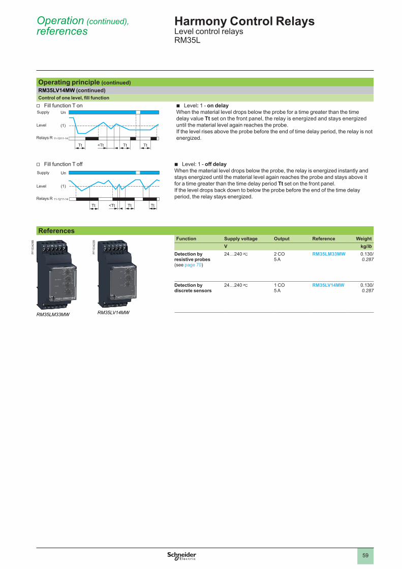
59
Operation (continued),references
Harmony Control Relays Level control relays RM35L
Operating principle (continued)RM35LV14MW (continued)Control of one level, fill function v Fill function T on
Un
(1)
11-12/11-14
Tt <Tt Tt Tt
Supply
Relays R
Level
b Level: 1 - on delayWhen the material level drops below the probe for a time greater than the time delay value Tt set on the front panel, the relay is energized and stays energized until the material level again reaches the probe. If the level rises above the probe before the end of time delay period, the relay is not energized.
v Fill function T offUn
Tt <Tt Tt Tt
(1)
11-12/11-14
Supply
Relays R
Level
b Level: 1 - off delay When the material level drops below the probe, the relay is energized instantly and stays energized until the material level again reaches the probe and stays above it for a time greater than the time delay period Tt set on the front panel. If the level drops back down to below the probe before the end of the time delay period, the relay stays energized.
ReferencesFunction Supply voltage Output Reference Weight
V kg/lbDetection by resistive probes(see page 70)
24…240 z 2 CO5 A
RM35LM33MW 0.130/ 0.287
Detection by discrete sensors
24…240 z 1 CO5 A
RM35LV14MW 0.130/ 0.287
RM35LM33MW
PF15
3429
B
RM35LV14MW
PF15
3422
B

60
Presentation,description, operation
Harmony Control Relays3-phase and 1-phase pump control relaysRM35BA
PresentationMeasurement and control relay RM35BA10 is used for control and monitoring of 3-phase and single-phase pumps.Functions RM35BA10
3-phase phase sequence3-phase phase loss3-phase overcurrent and undercurrent control1-phase overcurrent and undercurrent control
Function performedFunction not performed
These control relays allow: v Absence of one or more phases v Undercurrent for protection against dry running v Overcurrent for protection against overload
b Acceptance of different nominal voltage values: v 208…480 V a in 3-phase mode v 230 V a in 1-phase mode b Clip-on mounting on a 5 rail b Monitoring of their own supply voltage measured as a true rms value
They feature: b A sealable cover to help protect the settings b A control status indicator LED
Applications b Management of pumps
DescriptionRM35BA
1 Configuration: selection of active function and operating mode 3-ph/1-ph (Double - Single)
2 Overcurrent setting potentiometer > I3 Undercurrent setting potentiometer < I4 Time delay adjustment potentiometer Tt5 Starting inhibition time delay adjustment potentiometer Ti6 Spring for clip-on mounting on 35 mm/1.38 in. 5 rail
Operating principlePump control relay RM35BA10 can operate on a 1-phase or 3-phase supply and incorporates 3 functions in a single unit:
b Current control b Phase presence control (in 3-phase mode) b Phase sequence control (in 3-phase mode)
Function DiagramPower supply offPower supply onOutput 11-14, 21-24 openOutput 11-14, 21-24 closed
These relays have two operating modes which are designed to control a pump via two external signal inputs (Y1 and Y2). These two signal inputs are controlled by volt-free contacts.Control signal inputs Y1 and Y2 can be connected to:
b A level sensor b A level relay b A pressure sensor b A pushbutton, etc.
Fault signaling is by LEDs with differentiation of the reason for the fault.
RM35BA10The following operating mode is selected by using a switch:
b Single control b Double control b 1-phase or 3-phase supply
The position of the switch and the operating mode is read by the product on energization.
b If the switch position is changed while the device is operating, all the LEDs flash, but the product continues to operate normally with the function selected at the time of energization preceding the change of position.
b If the configuration switch is returned to the original position selected prior to the last energization, the LEDs return to their normal state.
RM35BA10
E1
Y1 12 11 14Y2
L2 L3L1
Def.
Un
R
> I
< I 345
21
6
Def. Yellow LED: indicates fault present statusUn Green LED: indicates that supply to the product is onR Yellow LED: indicates relay output status
RM35BA
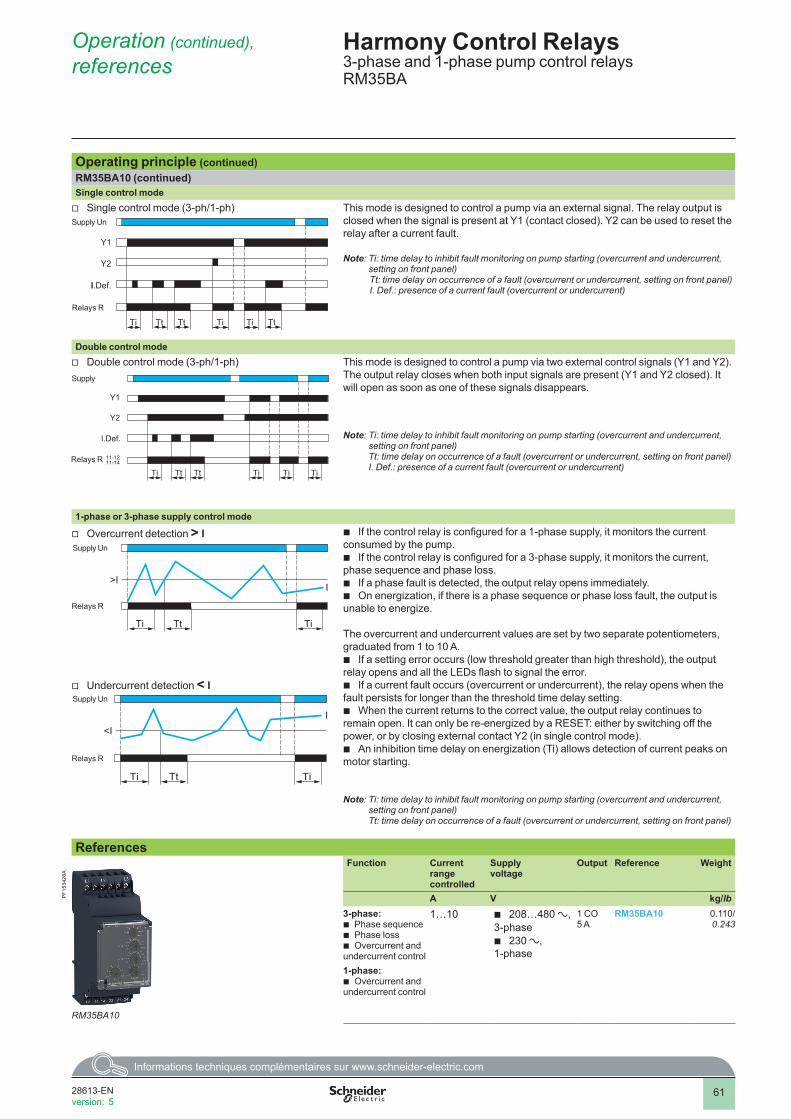
61
Harmony Control Relays3-phase and 1-phase pump control relaysRM35BA
Operation (continued), references
Operating principle (continued)RM35BA10 (continued)Single control mode v Single control mode (3-ph/1-ph)
Tt TtTtTi Ti Ti
Y1
Y2
II.Def.
11-1211-14Relays R
Supply UnThis mode is designed to control a pump via an external signal. The relay output is closed when the signal is present at Y1 (contact closed). Y2 can be used to reset the relay after a current fault.
Note: Ti: time delay to inhibit fault monitoring on pump starting (overcurrent and undercurrent, setting on front panel)Tt: time delay on occurrence of a fault (overcurrent or undercurrent, setting on front panel)I. Def.: presence of a current fault (overcurrent or undercurrent)
Double control mode v Double control mode (3-ph/1-ph)
TiTiTiTtTi Tt
Y1
Y2
I.Def.
11-1211-14Relays R
Supply
This mode is designed to control a pump via two external control signals (Y1 and Y2). The output relay closes when both input signals are present (Y1 and Y2 closed). It will open as soon as one of these signals disappears.
Note: Ti: time delay to inhibit fault monitoring on pump starting (overcurrent and undercurrent, setting on front panel) Tt: time delay on occurrence of a fault (overcurrent or undercurrent, setting on front panel) I. Def.: presence of a current fault (overcurrent or undercurrent)
1-phase or 3-phase supply control mode
v Overcurrent detection > I
Ti Tt Ti
I>I
11-12/11-14Relays R
Supply Un
b If the control relay is configured for a 1-phase supply, it monitors the current consumed by the pump.
b If the control relay is configured for a 3-phase supply, it monitors the current, phase sequence and phase loss.
b If a phase fault is detected, the output relay opens immediately. b On energization, if there is a phase sequence or phase loss fault, the output is
unable to energize.
The overcurrent and undercurrent values are set by two separate potentiometers, graduated from 1 to 10 A.
b If a setting error occurs (low threshold greater than high threshold), the output relay opens and all the LEDs flash to signal the error.
b If a current fault occurs (overcurrent or undercurrent), the relay opens when the fault persists for longer than the threshold time delay setting.
b When the current returns to the correct value, the output relay continues to remain open. It can only be re-energized by a RESET: either by switching off the power, or by closing external contact Y2 (in single control mode).
b An inhibition time delay on energization (Ti) allows detection of current peaks on motor starting.
Note: Ti: time delay to inhibit fault monitoring on pump starting (overcurrent and undercurrent, setting on front panel) Tt: time delay on occurrence of a fault (overcurrent or undercurrent, setting on front panel)
v Undercurrent detection < I
11-12/11-14
Ti Tt Ti
I<I
Relays R
Supply Un
ReferencesFunction Current
range controlled
Supply voltage
Output Reference Weight
A V kg/lb3-phase:
b Phase sequence b Phase loss b Overcurrent and
undercurrent control1-phase:
b Overcurrent and undercurrent control
1…10 b 208…480 a, 3-phase
b 230 a,1-phase
1 CO5 A
RM35BA10 0.110/ 0.243
RM35BA10
PF15
3428
A
2
1
3
4
5
6
7
8
9
10
2
1
3
4
5
6
7
8
9
10
28613-ENversion: 5
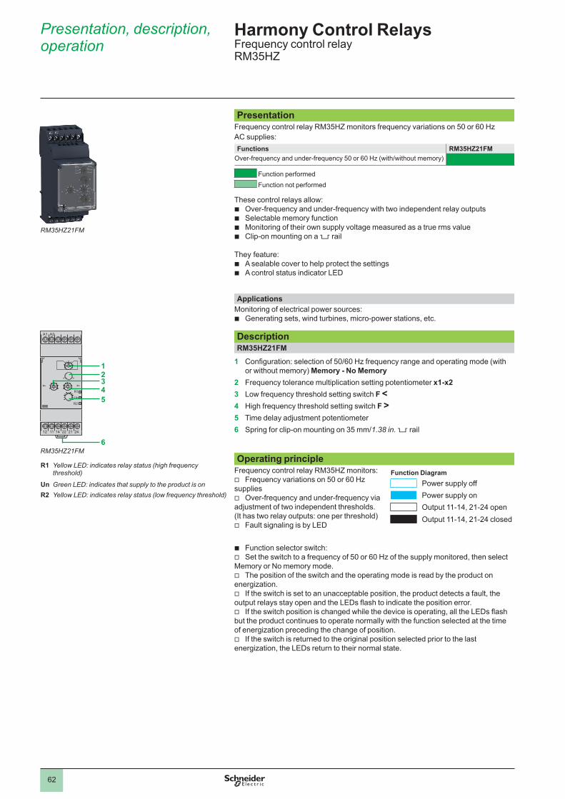
62
Presentation, description, operation
PresentationFrequency control relay RM35HZ monitors frequency variations on 50 or 60 Hz AC supplies:Functions RM35HZ21FM
Over-frequency and under-frequency 50 or 60 Hz (with/without memory)
Function performed Function not performed
These control relays allow: b Over-frequency and under-frequency with two independent relay outputs b Selectable memory function b Monitoring of their own supply voltage measured as a true rms value b Clip-on mounting on a 5 rail
They feature: b A sealable cover to help protect the settings b A control status indicator LED
ApplicationsMonitoring of electrical power sources:
b Generating sets, wind turbines, micro-power stations, etc.
DescriptionRM35HZ21FM
1 Configuration: selection of 50/60 Hz frequency range and operating mode (with or without memory) Memory - No Memory
2 Frequency tolerance multiplication setting potentiometer x1-x23 Low frequency threshold setting switch F <4 High frequency threshold setting switch F >5 Time delay adjustment potentiometer6 Spring for clip-on mounting on 35 mm/1.38 in. 5 rail
Operating principleFrequency control relay RM35HZ monitors:
v Frequency variations on 50 or 60 Hz supplies
v Over-frequency and under-frequency via adjustment of two independent thresholds. (It has two relay outputs: one per threshold)
v Fault signaling is by LED
Function DiagramPower supply offPower supply onOutput 11-14, 21-24 openOutput 11-14, 21-24 closed
b Function selector switch: v Set the switch to a frequency of 50 or 60 Hz of the supply monitored, then select
Memory or No memory mode. v The position of the switch and the operating mode is read by the product on
energization. v If the switch is set to an unacceptable position, the product detects a fault, the
output relays stay open and the LEDs flash to indicate the position error. v If the switch position is changed while the device is operating, all the LEDs flash
but the product continues to operate normally with the function selected at the time of energization preceding the change of position.
v If the switch is returned to the original position selected prior to the last energization, the LEDs return to their normal state.
Harmony Control RelaysFrequency control relayRM35HZ
RM35HZ21FM
4.1
A1
12 2214 21 2411
A2
R1
Un
R2
2345
6
R1 Yellow LED: indicates relay status (high frequency threshold)
Un Green LED: indicates that supply to the product is onR2 Yellow LED: indicates relay status (low frequency threshold)
RM35HZ21FM
1
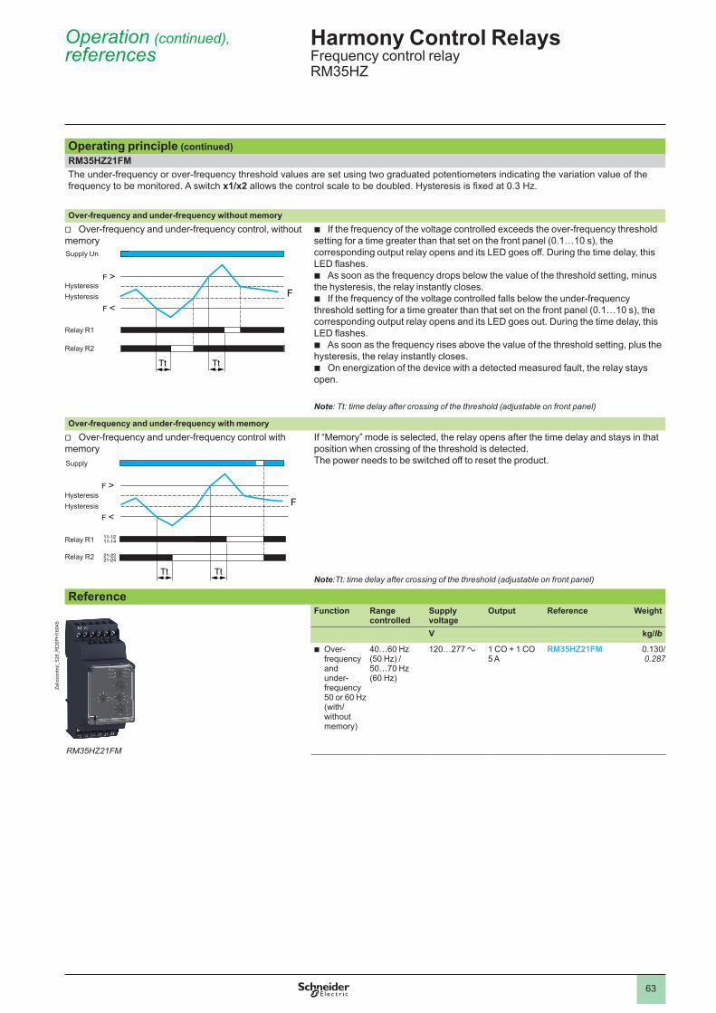
63
Operating principle (continued)RM35HZ21FMThe under-frequency or over-frequency threshold values are set using two graduated potentiometers indicating the variation value of the frequency to be monitored. A switch x1/x2 allows the control scale to be doubled. Hysteresis is fixed at 0.3 Hz.
Over-frequency and under-frequency without memory v Over-frequency and under-frequency control, without
memory
Tt Tt
F
11-1211-14
21-2221-24
F >
F <
Supply Un
HysteresisHysteresis
Relay R1
Relay R2
b If the frequency of the voltage controlled exceeds the over-frequency threshold setting for a time greater than that set on the front panel (0.1…10 s), the corresponding output relay opens and its LED goes off. During the time delay, this LED flashes.
b As soon as the frequency drops below the value of the threshold setting, minus the hysteresis, the relay instantly closes.
b If the frequency of the voltage controlled falls below the under-frequency threshold setting for a time greater than that set on the front panel (0.1…10 s), the corresponding output relay opens and its LED goes out. During the time delay, this LED flashes.
b As soon as the frequency rises above the value of the threshold setting, plus the hysteresis, the relay instantly closes.
b On energization of the device with a detected measured fault, the relay stays open.
Note: Tt: time delay after crossing of the threshold (adjustable on front panel)
Over-frequency and under-frequency with memory v Over-frequency and under-frequency control with
memory
Tt Tt
F
11-1211-14
21-2221-24
F >
F <
Supply
HysteresisHysteresis
Relay R1
Relay R2
If “Memory” mode is selected, the relay opens after the time delay and stays in that position when crossing of the threshold is detected.The power needs to be switched off to reset the product.
Note:Tt: time delay after crossing of the threshold (adjustable on front panel)
ReferenceFunction Range
controlledSupply voltage
Output Reference Weight
V kg/lb
b Over-frequency and under-frequency 50 or 60 Hz (with/without memory)
40…60 Hz (50 Hz) / 50…70 Hz (60 Hz)
120…277 a 1 CO + 1 CO 5 A
RM35HZ21FM 0.130/ 0.287
Harmony Control RelaysFrequency control relayRM35HZ
Operation (continued), references
RM35HZ21FM
Zelio
cont
rol_
528_
RD
SPH
1604
5
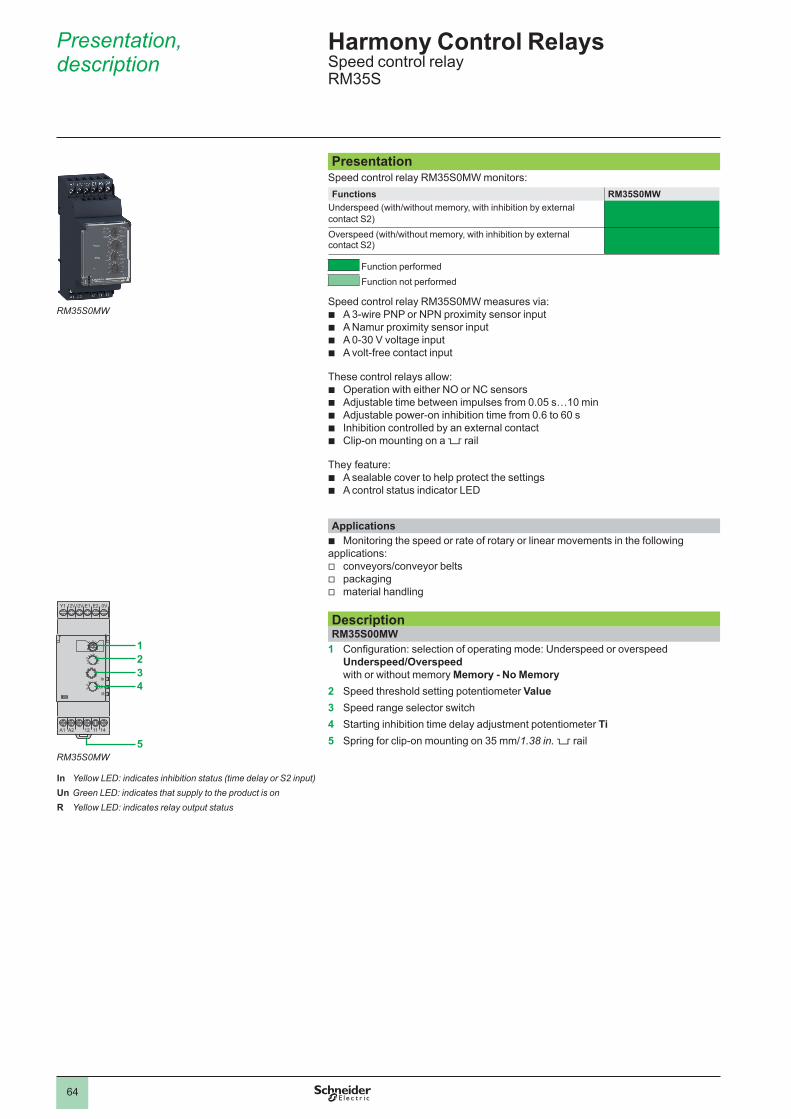
64
Presentation, description
PresentationSpeed control relay RM35S0MW monitors: Functions RM35S0MW
Underspeed (with/without memory, with inhibition by external contact S2) Overspeed (with/without memory, with inhibition by external contact S2)
Function performed Function not performed
Speed control relay RM35S0MW measures via: b A 3-wire PNP or NPN proximity sensor input b A Namur proximity sensor input b A 0-30 V voltage input b A volt-free contact input
These control relays allow: b Operation with either NO or NC sensors b Adjustable time between impulses from 0.05 s…10 min b Adjustable power-on inhibition time from 0.6 to 60 s b Inhibition controlled by an external contact b Clip-on mounting on a 5 rail
They feature: b A sealable cover to help protect the settings b A control status indicator LED
Applications b Monitoring the speed or rate of rotary or linear movements in the following
applications: v conveyors/conveyor belts v packaging v material handling
DescriptionRM35S00MW
1 Configuration: selection of operating mode: Underspeed or overspeed Underspeed/Overspeed with or without memory Memory - No Memory
2 Speed threshold setting potentiometer Value3 Speed range selector switch4 Starting inhibition time delay adjustment potentiometer Ti5 Spring for clip-on mounting on 35 mm/1.38 in. 5 rail
Harmony Control RelaysSpeed control relayRM35S
Y1
A1 12 11 14A2
12V12V E1 E2 0V
RUn
In
1234
5
RM35S0MW
5.1
In Yellow LED: indicates inhibition status (time delay or S2 input)Un Green LED: indicates that supply to the product is onR Yellow LED: indicates relay output status
RM35S0MW

65
Operation
Operating principleRelay RM35S0MW monitors the speed (rate, frequency) of a process (conveyor, conveyor belt, etc.) using discrete sensors:
v 3-wire PNP or NPN proximity sensor v 0-30 V voltage input v NAMUR proximity sensor v volt-free contact
It can be used for monitoring underspeed or overspeed.
Function DiagramPower supply offPower supply onOutput 11-14, 21-24 openOutput 11-14, 21-24 closed
RM35S0MWThe control relay measures the speed as follows:
v The cycle of the process being monitored is a series of impulses characterized by a two-state signal: high and low. v The speed is obtained by measuring the period of this signal, from the detection of first change of state (either rising or falling edge). v Digital processing of the signal allows the disparity between the signals to be calculated. v On energization or after appearance (or reappearance) of the sensor signal, detection (characterization) of the signal requires processing
of one or two periods. During this time, control is inoperative.
The operating modes are selected by using the switch: v Underspeed without memory v Underspeed with memory v Overspeed without memory v Overspeed with memory
Underspeed control without memory v Underspeed control, without memory
VVs
Ti Ti
1 sec mini
In
11-12/11-14
Supply UnHysteresisThreshold
Relays R
At the end of the starting inhibition time delay “Ti”, as soon as the speed measured drops below the threshold setting, the output relay changes state from “closed” to “open”.It returns to its initial state when the speed is again higher than the threshold plus hysteresis (fixed at 5% of the threshold setting).When power is restored, after a break having lasted at least 1 s, the relay is in the “closed” state during the time delay and stays in that state for as long as the speed remains higher than the threshold.
Underspeed control with memory v Underspeed control, with memory
Hysteresis
Supply Un
Threshold
1 sec mini
50 ms mini
V
S2
Ti Ti
Vs
In
11-12/11-14Relays R
When relay RM35S has been configured in “memory” mode, if underspeed is detected, the output relay stays in the “open” state, irrespective of any further changes in the process speed. It will not be able to return to the “closed” state until contact S2 closes (for at least 50 ms). If, when S2 re-opens, the speed is not high enough, the relay returns to “open” state.Relay RM35S can also be reset by a power break (at least 1 s); the relay then returns to the “closed” state for at least the duration of the time delay, irrespective of the process speed.
Harmony Control RelaysSpeed control relayRM35S

66
Operation (continued) Harmony Control RelaysSpeed control relayRM35S
Operating principle (continued)RM35S0MWUnderspeed control with inhibition by S2 v With inhibition by S2 Inhib./S2
Ti
V
S2
Vs
In
11-12/11-14
Hysteresis
Supply Un
Threshold
Relays R
On energization, to allow the process being monitored to reach its nominal operating speed, relay RM35S is inhibited for a time delay adjustable from 0.6…60 s. This time delay can be adjusted (shortened or lengthened) during inhibition.Relay RM35S can also be inhibited by closing of contact S2: on starting, for example, if the process run-up to speed time is greater than 60 s, or at any time during operation.Whether it results from a starting inhibition time delay or closing of S2, inhibition keeps the output relay in the “closed” position and is signaled by illumination of the inhibition LED.If, after lifting of inhibition (end of starting inhibition time delay or opening of contact S2), the signal detection phase has not been completed, the relay drops out after the set wait time between two impulses (measured from the end of inhibition). Inhibition should last as long as is necessary for the product to detect at least 2 periods.When the signal has not been ‘characterized’ by the end of the inhibition period, the “inhibition” LED flashes for as long as speed measurement is impossible.It is also possible to inhibit relay RM35S at any time, during operation, by closing S2.
Overspeed control without memory v Overspeed control, without memory
V
Ti Ti
1 sec mini
In
11-12/11-14
Vs
Supply Un
Relays R
HysteresisThreshold
At the end of the starting inhibition time delay, “Ti”, as soon as the speed measured is higher than the threshold setting, the output relay changes state from “closed” to “open”.It returns to its initial state when the speed is again lower than the threshold minus hysteresis (fixed at 5% of the threshold setting).When power is restored to relay RM35S, after a break having lasted at least 1 s, the relay is in the “closed” state during the time delay and stays in that state for as long as the speed remains lower than the threshold.
Overspeed control with memory v Overspeed control, with memory
V
1 sec mini
50 ms mini
Ti Ti
S2
Vs
In
11-12/11-14
Supply Un
Relays R
HysteresisThreshold
When relay RM35S has been configured in “memory” mode, if overspeed is detected, the output relay stays in the “open” state, irrespective of any further changes in the process speed. It will not be able to return to the “closed” state until contact S2 closes (for at least 50 ms). If, when S2 re-opens, the speed is too high, the relay returns to the “open” state.Relay RM35S can also be reset by a power break (at least 1 s); the relay then returns to the “closed” state for at least the duration of the time delay, irrespective of the process speed.

67
Operation (continued),reference
Harmony Control RelaysSpeed control relayRM35S
Operating principle (continued)RM35S0MWOverspeed control with inhibition by S2 v With inhibition by S2. Inhib./S2
Ti
V
S2Vs
In
11-12/11-14
Supply Un
Relays R
HysteresisThreshold
On energization, in order to allow the process being monitored to reach its nominal operating speed, relay RM35S is inhibited for a time delay adjustable from 0.6…60 s. This time delay can be modified (shortened or lengthened) during inhibition.Relay RM35S can also be inhibited by closing of contact S2: on starting, for example, if the process run-up to speed time is greater than 60 s, or at any time during operation.Whether it results from a starting inhibition time delay or closing of S2, inhibition keeps the output relay in the “closed” position and is signaled by illumination of the inhibition LED.If, after lifting of inhibition (end of starting inhibition time delay or opening of contact S2), the signal detection phase has not been completed, the relay drops out after the set wait time between two impulses (measured from the end of inhibition).Inhibition should last as long as is necessary for the product to detect at least 2 periods.When the signal has not been ‘characterized’ by the end of the inhibition period, the “inhibition” LED flashes for as long as speed measurement is impossible.It is also possible to inhibit relay RM35S at any time, during operation, by closing S2.
ReferenceFunction Supply
voltage V
MeasurementInput
Output Reference Weightkg/lb
b Underspeed (with/without memory)
b Overspeed (with/without memory)
24…240 z b 3-wire PNP or NPN proximity sensor
b Namur proximity sensor
b 0-30 V voltageb Volt-free contact
1 CO 5 A
RM35S0MW 0.130/ 0.287
RM35S0MW
RM
_CR
M19
254C

68
Presentation, description, operation
Harmony Control RelaysTemperature control relays for elevator machine rooms and 3-phase suppliesRM35ATL, RM35ATR, and RM35ATW
PresentationMeasurement and control relays RM35ATL0MW, RM35ATR5MW and RM35ATW5MW are designed for monitoring the temperature in elevator machine rooms, in compliance with directive EN81.Functions RM35ATL0MW RM35ATR5MW RM35ATW5MW
Overtemperature (34…46 °C)Undertemperature (-1…11 °C)Phase sequencePhase loss
Function performedFunction not performed
These control relays allow: b PT100 input b Adjustable control around 5 °C and 40 °C b Independent adjustment of high and low thresholds b Possibility of integrated phase control b Clip-on mounting on a 5 rail
They feature: b A sealable cover to help protect the settings b A control status indicator LED
Applications b Temperature control for elevator machine rooms
DescriptionRM35ATL0MW, RM35ATR5MW
1 High temperature threshold setting potentiometer q>2 Potentiometer for adjustment of time delay on crossing of temperature
threshold Tt3 Low temperature threshold setting potentiometer q<4 Spring for clip-on mounting on 35 mm/1.38 in. 5 rail5 High temperature threshold contact (11-14)6 Low temperature threshold contact (21-24)7 High and low temperature threshold contacts
RM35ATW5MW
1 High temperature threshold setting potentiometer q>2 Potentiometer for adjustment of time delay on crossing of
temperature threshold Tt3 Low temperature threshold setting potentiometer q<4 Spring for clip-on mounting on 35 mm/1.38 in. 5 rail5 Temperature relay contact (11-14)6 Phase relay contact (21-44)
Operating principleTemperature control relays for elevator machine rooms are designed to monitor the stated temperature between 5 °C and 40 °C in compliance with directive EN81.
Function DiagramPower supply offPower supply onOutput 11-14, 21-24 openOutput 11-14, 21-24 closed
RM35ATp0MW
A
A1 1411 21 24A2
B B
>
<Un
123
654
A
A1 12 11 14A2
B B
>
<Un
7
321
4
A L1 L2 L3
A1 1411 21 24A2
B B
UnL1
L2L3
<<
123
654
> Yellow LED: indicates relay output status (high temperature threshold)
Un Green LED: indicates that supply to the product is on< Yellow LED: indicates relay output status (low
temperature threshold)
<q°< Yellow LED: indicates temperature relay output status R1Un Green LED: indicates that supply to the product is on
L1
L2L3Yellow LED: indicates phase relay output status R2
RM35ATL0MW RM35ATR5MW
RM35ATW5MW

69
Harmony Control RelaysTemperature control relays for elevator machine rooms and 3-phase suppliesRM35ATL, RM35ATR, and RM35ATW
Operation (continued), references
Operating principle (continued)RM35ATL0MWTemperature control by PT100 probe v Temperature control by PT100 probe
Tt Tt
>
<
Relays R
Hysteresis
Supply Un
Hysteresis
After a delay on pick-up after energization, and for as long as the temperature monitored by the PT100 probe remains between the two thresholds set on the front panel, the output relay is closed and the yellow LEDs are on.When the temperature crosses one of the threshold settings on the front panel (high or low threshold), the time delay set on the front panel (Tt) is activated. The yellow LED corresponding to the threshold crossed (low or high) flashes.At the end of the time delay, if the temperature is still outside the threshold setting, the output relay opens and the yellow LED corresponding to the threshold crossed goes out.The output relay closes instantly (within the response time on disappearance of a fault) when the temperature returns within the window of the two threshold settings on the front panel, plus the fixed hysteresis.If the PT100 probe is incorrectly wired (missing or short-circuited) the relay is open and the 3 LEDs flash.Note: Tt: time delay after crossing of the temperature threshold (adjustable on front panel)
RM35ATR5MWTemperature control by PT100 probe v Temperature control by PT100 probe
Tt Tt
>Un
<
Relay R1
Hysteresis
Supply
Hysteresis
Relay R2
After a delay on pick-up after energization, and for as long as the temperature monitored by the PT100 probe remains between the two threshold settings on the front panel, the output relays are closed and their yellow LEDs are on.When the temperature crosses one of the threshold settings on the front panel (high or low threshold), the time delay set on the front panel (Tt) is activated. The yellow LED corresponding to the threshold crossed (low or high), flashes.At the end of the time delay, if the temperature is still outside one of the threshold settings, the corresponding output relay opens and the yellow LED corresponding to the threshold crossed goes out.The output relay closes instantly (response time on disappearance of a fault) when the temperature returns within the window of the two threshold settings on the front panel, plus (or minus) the fixed hysteresis.If the PT100 probe is incorrectly wired (missing or short-circuited) the relays are open and the 3 LEDs flash.Note: Tt: time delay after crossing of the temperature threshold (adjustable on front panel)
RM35ATW5MWTemperature and phase control v Temperature control by PT100 probe v Sequence of phases L1, L2, and L3 v Phase loss
Tt Tt
>
<
Relay R1
Hysteresis
Supply Un
Hysteresis
After a delay on pick-up after energization, and for as long as the temperature monitored by the PT100 probe remains between the two threshold settings on the front panel, the temperature relay R1 is closed.When the temperature crosses one of the threshold settings on the front panel (high or low threshold), the time delay set on the front panel (Tt) is activated. The yellow temperature LED flashes. At the end of the time delay, if the temperature is still outside the threshold setting, the output relay R1 opens and the yellow LED goes out.The output relay R1 closes instantly when the temperature returns to within the window of the two threshold settings on the front panel, plus or minus the fixed hysteresis.The device also monitors the correct sequence of phases L1, L2, and L3 of the 3-phase supply and total phase loss, even in the case of phase regeneration (< 70%).After a delay on pick-up after energization, and for as long as phase presence and phase sequence are correct, relay R2 and the “phase” LED are On. When a fault appears, the “phase” relay opens and the “phase” LED instantly goes out (response time on appearance of a fault). When the fault disappears, the phase control relay and LED are activated (response time on disappearance of a fault).If the PT100 probe is incorrectly wired (missing or short-circuited) relay R1 is open and LED R1 flashes.Note: Tt: time delay after crossing of the temperature threshold (adjustable on front panel)
ReferencesFunction Supply
voltage3-phase control
Output Reference Weight
V V kg/lb b Overtemperature: 34…46 °C b Undertemperature
- 1…11 °C
24…240 z
– 1 CO5 A
RM35ATL0MW 0.130/ 0.287
– 2 NO5 A
RM35ATR5MW 0.130/ 0.287
b Overtemperature: 34…46 °C b Undertemperature - 1…11 °C b Phase sequence b Phase loss
24…240 z
208…480 a
2 NO5 A
RM35ATW5MW 0.130/ 0.287
RM35ATR5MW
Zelio
cont
rol_
528_
RD
SPH
1604
4
RM35ATL0MW
Zelio
cont
rol_
528_
RD
SPH
1604
4
2
1
3
4
5
6
7
8
9
10
2
1
3
4
5
6
7
8
9
10
28612-ENversion: 5

70
References
ProbesApplication No.
of probes
Length Opera-ting temper-ature
Maximum pressure
Reference Weight
mm/in . °C/°F kg/cm2 kg/lbRecommended for drinks vending machines and where installation space is limited (Stainless steel)
3 1000/ 39.37
80/ 176
2 RM79696044 0.800/ 1.764
Suitable for boilers, pressure vessels and high temperature conditions (1) (304 stainless steel)
1 1000/ 39.37
200/ 392
25 RM79696014 0.360/ 0.794
Description Material Reference Weightkg/lb
Protected probe for mounting by suspension
Protective shell PUC (S7) Electrode: stainless steel
RM79696043 0.150/ 0.331
Description Type of installation
Maximum operating temperature
Reference Weight
°C/°F kg/lbLiquid level control probe
Suspended by cable
100/ 212
LA9RM201 0.100/0.220
(1) 3/8" BSP mounting thread with hexagonal head. Use a 24 mm (0.95 in.) spanner for tightening.
RM79696043
5610
34
LA9RM201
Harmony Control RelaysAccessories for Liquid level control relaysElectrode holders and probes
5610
89

71
Electrode holdersDescription Material Reference Weight
kg/lbElectrode for use up to 350 °C and 15 kg/cm2 (1)
Ceramic-insulated stainless steel
RM79696006 0.150/ 0.331
(1) 3/8" BSP mounting thread.RM79696006
5610
35
5610
36
Harmony Control RelaysAccessories for Liquid level control relaysElectrode holders and probes
References (continued)

72
Index Harmony Control RelaysNear Field Communication and conventional Control Relays
LLA9RM201 70
RRM17JC00MW 45RM17TA00 23RM17TE00 23RM17TG00 13RM17TG20 13RM17TT00 23RM17TU00 23RM17UAS14 37RM17UAS15 37RM17UAS16 37RM17UAS15315M 37RM17UB310 29RM17UBE15 37RM17UBE16 37RM22JA21MR 49RM22JA31MR 49RM22LA32MR 55RM22LG11MR 55RM22LG11MT 55RM22TA31 19RM22TA33 19RM22TG20 19RM22TR31 19RM22TR33 19RM22TU21 19RM22TU23 19RM22UA21MR 43RM22UA22MR 43RM22UA23MR 43RM22UA31MR 43RM22UA32MR 43RM22UA33MR 43RM22UA33MT 43RM22UB34 43RM35ATL0MW 69RM35ATR5MW 69RM35ATW5MW 69RM35BA10 61RM35HZ21FM 63RM35JA31MW 51RM35JA32MR 49RM35JA32MT 49RM35JA32MW 51RM35LM33MW 59RM35LV14MW 59RM35S0MW 67RM35TF30 25RM35TM50MW 33RM35TM250MW 33RM35UA11MW 39RM35UA12MW 39RM35UA13MW 39RM35UB3N30 29RM35UB330 29RM79696006 71RM79696014 70RM79696043 70RM79696044 70RMNF22TB30 15

Learn more about our products at www.se.com/Harmony Control Relays
The information provided in this documentation contains general descriptions and/or technical characteristics of the performance of the products contained herein. This documentation is not intended as a substitute for and is not to be used for determining suitability or reliability of these products for specific user applications. It is the duty of any such user or integrator to perform the appropriate and complete risk analysis, evaluation and testing of the products with respect to the relevant specific application or use thereof. Neither Schneider Electric nor any of its affiliates or subsidiaries shall be responsible or liable for misuse of the information contained herein.
Design: Schneider ElectricPhotos: Schneider Electric
DIA5ED2160501ENOctober 2021 - V6.0
Schneider Electric Industries SASHead Office35, rue Joseph Monier - CS 30323F-92500 Rueil-Malmaison CedexFrance