catalogo de sensores de flujo ege - sistemamid.com
TRANSCRIPT

Catalogue 2005 / 2006
Special-Sensorsfor
Automation WWW.VARITEL.COM
Flow controllersAir flow controllers
Contents
WWW.VARITEL.COM
Technique and application for flow sensorsTechnique and application for flow sensors, amplifiers und compact models . . . . . . .1.01 - 1.05Terminology . . . . . . . . . . . . . . . . . . . . . . . . . . . . . . . . . . . . . . . . . . . . . . . . . . . . . . . . . . . . . . .1.06Setting instructions . . . . . . . . . . . . . . . . . . . . . . . . . . . . . . . . . . . . . . . . . . . . . . . . . . . . . . . . .1.07Ex area certification, valid standards . . . . . . . . . . . . . . . . . . . . . . . . . . . . . . . . . . . . . . . . . . . .1.08
Flow controller Series 400 / Series 500Short sensors Series STK / ST . . . . . . . . . . . . . . . . . . . . . . . . . . . . . . . . . . . . . . . . . . .1.10 - 1.12High temperature sensors Series ST . . . . . . . . . . . . . . . . . . . . . . . . . . . . . . . . . . . . . .1.13 - 1.14Chemical sensors Series STA . . . . . . . . . . . . . . . . . . . . . . . . . . . . . . . . . . . . . . . . . . . . . . . . .1.15Food industry sensors Series SCB / STB / STC . . . . . . . . . . . . . . . . . . . . . . . . . . . . . . . . . . .1.16Compact model Series SC 440 . . . . . . . . . . . . . . . . . . . . . . . . . . . . . . . . . . . . . . . . . . . . . . . .1.17Compact model Series SN 450 . . . . . . . . . . . . . . . . . . . . . . . . . . . . . . . . . . . . . . . . . . .1.18 - 1.21Compact model with analog output Series SN 450 . . . . . . . . . . . . . . . . . . . . . . . . . . . . . . . . .1.22Compact model with 2 switching points Series SN 450 . . . . . . . . . . . . . . . . . . . . . . . . . . . . .1.23Compact model with temperature control Series SNT 450 . . . . . . . . . . . . . . . . . . . . . .1.24 - 1.26Compact model with turn on/off delay Series SN 450 . . . . . . . . . . . . . . . . . . . . . . . . . . . . . . .1.27Inline-compact model Series SDN . . . . . . . . . . . . . . . . . . . . . . . . . . . . . . . . . . . . . . . . .1.28 - 1.33Inline-sensors Series SD . . . . . . . . . . . . . . . . . . . . . . . . . . . . . . . . . . . . . . . . . . . . . . . . . . . . .1.34Amplifiers for flow controller . . . . . . . . . . . . . . . . . . . . . . . . . . . . . . . . . . . . . . . . . . . . .1.35 - 1.36
Air flow controller Series 400 / Series 500Air flow controller Series LTZ 421 . . . . . . . . . . . . . . . . . . . . . . . . . . . . . . . . . . . . . . . . . . . . . .1.38Compact model Series LN / LG / LD . . . . . . . . . . . . . . . . . . . . . . . . . . . . . . . . . . . . . . .1.39 - 1.41Compact model with analog output Series LNZ 450 . . . . . . . . . . . . . . . . . . . . . . . . . . . . . . . .1.42Compact model Series LNZ 450 . . . . . . . . . . . . . . . . . . . . . . . . . . . . . . . . . . . . . . . . . . . . . . .1.43Compact model Series LN 450 . . . . . . . . . . . . . . . . . . . . . . . . . . . . . . . . . . . . . . . . . . . . . . . .1.44Compact model with analog output Series LN 450 . . . . . . . . . . . . . . . . . . . . . . . . . . . . . . . . .1.45
Flow controller for Ex-applications Series Flow sensor Zone 0 with terminal clamps Series STSEX . . . . . . . . . . . . . . . . . . . . . . . . . . . .1.48Flow sensor Zone 0 - Zone 1 - Zone 1 high temperature 120 °C Series STS / ST . . . .1.49 - 1.57Air-flow sensor Zone 0 - Zone 1 - Zone 20 Series STS . . . . . . . . . . . . . . . . . . . . . . . . .1.58 - 1.59Inline-flow controller Zone 1 . . . . . . . . . . . . . . . . . . . . . . . . . . . . . . . . . . . . . . . . . . . . . . . . . .1.60Lightning protection . . . . . . . . . . . . . . . . . . . . . . . . . . . . . . . . . . . . . . . . . . . . . . . . . . . . . . . . .1.61Amplifier . . . . . . . . . . . . . . . . . . . . . . . . . . . . . . . . . . . . . . . . . . . . . . . . . . . . . . . . . . . . .1.62 - 1.66
Accessories / CertificatesUniversal-plug system M12 . . . . . . . . . . . . . . . . . . . . . . . . . . . . . . . . . . . . . . . . . . . . . .1.68 - 1.69Cable . . . . . . . . . . . . . . . . . . . . . . . . . . . . . . . . . . . . . . . . . . . . . . . . . . . . . . . . . . . . . . . . . . . .1.70Accessories / Assembly parts . . . . . . . . . . . . . . . . . . . . . . . . . . . . . . . . . . . . . . . . . . . .1.71 - 1.72Certificates . . . . . . . . . . . . . . . . . . . . . . . . . . . . . . . . . . . . . . . . . . . . . . . . . . . . . . . . . . . . . . . .1.73
Technical alterations are reserved to us without prior announcement.

Technique and Application
E10205 1.01
Function
The function of the flow controller is based on the thermo-dynamic principle.The sensor is heated internally a few degrees C comparedto the medium into which it projects. When the mediumflows, the heat generated in the sensor is conducted awayby the medium, i. e. the sensor cools down. The tempera-ture within the sensor is measured and compared to thetemperature of the medium. The state of flow can be derivedfor each medium by the temperature difference attained.
Function of thermodynamic flow controllers
On the basis of this functional principle EGE manufacturesflow monitors for liquid and gaseous media.
Areas of application for flow monitors
Thermodynamic flow monitors function without anymoving parts, therefore they are not subject to failure dueto corroded bearings, torn impellers or deflector deforma-tion. This reliability is highly valued in many industries.Today, flow monitors are used both in liquids and in air,and are employed even in explosive environments.
Monitoring of cooling
– The cooling water on welding machinery is monitoredusing compact stainless steel devices. This ensures suf-ficient cooling even for rapid cycles, otherwise the wel-ding robot will be switched off.
– The cooling lubricant flow is monitored continuously inprocessing centres. The tools are protected and have agreater service life.
– In metal processing, e.g. rolling mills and wire drawingmachines, the rolls and coils will be cooled continually.This is monitored by thermodynamic sensors. Due to therough environmental conditions the sensors are desi-gned for up to 160 °C and settings are made away fromthe heat with special amplifiers.
Monitoring of flow medium
–The run-dry protection of pumps is a frequent applica-tion, which often uses compact sensors with time delay.
– In dosing technology the aggregate, usually small flowquantities, is measured exactly by means of inline sen-sors. These sensors are inserted like a pipe into the line.
– Monitoring of filters and sieves can be ensured bymedium flow control; if the flow is progressively redu-ced, the filter must be renewed. Where this is not carriedout, the pump is switched off in a second stage shouldthe medium flow drop further. This uses a sensor withtwo switching points.
Run-dry protection of a feed pump
Sensors for explosive hazard environments
–The monitoring of cleaning processes using aggressivemedia at times is often only possible with special mate-rials, e.g. hastelloy or tantalum.
– Extraction systems for hazardous vapours at laboratoryworkstations as well as the hall ventilation in the hexaneprocessing industry are monitored using airflow sensors.
– CIP/SIP processes can be monitored and documentedwith flow monitors.
WWW.VARITEL.COM
Flow
No Flow
Technique and Application
WWW.VARITEL.COM1.02 E10205
Lateral installation Underside installation
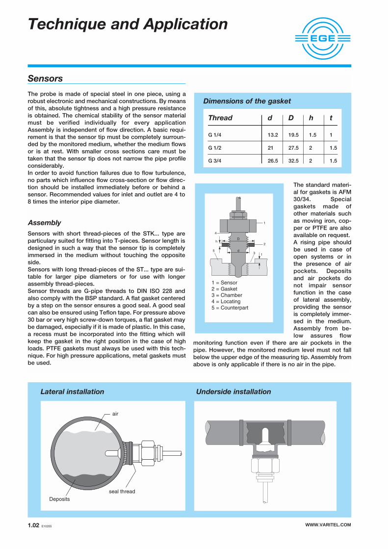
Sensors
The probe is made of special steel in one piece, using arobust electronic and mechanical constructions. By meansof this, absolute tightness and a high pressure resistanceis obtained. The chemical stability of the sensor materialmust be verified individually for every applicationAssembly is independent of flow direction. A basic requi-rement is that the sensor tip must be completely surroun-ded by the monitored medium, whether the medium flowsor is at rest. With smaller cross sections care must betaken that the sensor tip does not narrow the pipe profileconsiderably.In order to avoid function failures due to flow turbulence,no parts which influence flow cross-section or flow direc-tion should be installed immediately before or behind asensor. Recommended values for inlet and outlet are 4 to8 times the interior pipe diameter.
Assembly
Sensors with short thread-pieces of the STK... type areparticulary suited for fitting into T-pieces. Sensor length isdesigned in such a way that the sensor tip is completelyimmersed in the medium without touching the oppositeside.Sensors with long thread-pieces of the ST... type are sui-table for larger pipe diameters or for use with longerassembly thread-pieces.Sensor threads are G-pipe threads to DIN ISO 228 andalso comply with the BSP standard. A flat gasket centeredby a step on the sensor ensures a good seal. A good sealcan also be ensured using Teflon tape. For pressure above30 bar or very high screw-down torques, a flat gasket maybe damaged, especially if it is made of plastic. In this case,a recess must be incorporated into the fitting which willkeep the gasket in the right position in the case of highloads. PTFE gaskets must always be used with this tech-nique. For high pressure applications, metal gaskets mustbe used.
The standard materi-al for gaskets is AFM30/34. Specialgaskets made ofother materials suchas moving iron, cop-per or PTFE are alsoavailable on request.A rising pipe shouldbe used in case ofopen systems or inthe presence of airpockets. Depositsand air pockets donot impair sensorfunction in the caseof lateral assembly,providing the sensoris completely immer-sed in the medium.Assembly from be-low assures flow
monitoring function even if there are air pockets in thepipe. However, the monitored medium level must not fallbelow the upper edge of the measuring tip. Assembly fromabove is only applicable if there is no air in the pipe.
Dimensions of the gasket
D
2
t
1
4
5 d
h
3
1 = Sensor2 = Gasket3 = Chamber 4 = Locating5 = Counterpart
Thread D hd t
G 1/4 13.2 1.519.5 1
G 1/2 21 227.5 1.5
G 3/4 26.5 232.5 1.5
seal thread
air
Deposits

Technique and Application
WWW.VARITEL.COM E10205 1.03
NPT threads
NPT threads can be provided as an alternative for all typeswhich have a G1/2 or a G3/4 thread. NPT threads are coni-cal and must be screwed into an equally conical counter-part. Two types of NPT threads must be distinguished:
NPT thread to ANSI B 1.20.1
This thread does not ensure a good seal by itself andrequires the use of a sealing medium, e.g. Teflon tape. It isnot possible to use flat gaskets with this type of thread.
NPT thread to ANSI B 1.20.3
This thread does ensure a good seal by itself and requiresno further sealing medium. When this type of thread isused, special attention must be paid to the kind of metalused for both parts of the thread, so as to avoid metal sei-zing when the parts are screwed tight.
Media
The sensitivity of thermodynamic flow monitors dependson the thermal characteristics of a medium. The detectionrange of a standard sensor for oil, for example, is threetimes as great than for water and for air is approx. 30 timesgreater than for water due to the reduced heat conductivi-ty. Unless stated otherwise, the technical sensor data arespecified for water.
Flange
Standardised pipe connections are required particularly inthe chemical, pharmaceutical and foodstuff industries.Sensors for use in these areas are supplied with flangeconnections per DIN or ASME. Sensor and flange form acorrosion-proof connection using laser or inert gas shiel-ded arc welding.
Food-approved screw connections
For hygienic reasons the food and pharmaceutical indu-stries place special demands on the mechanical and elec-tronic characteristics of sensors.
Flow monitors with food-approved connections, e.g. Triclamp or dairy pipe connections (DIN 11851) complywith the 3-A sanitary standard 28-03. Due to the tempera-ture changes involved, the usual cleaning cycles CIP andSIP place a particular demand on sensor electronics.Therefore, special protective measures are taken. Sensormaterials for these applications is mainly the special steelAISI 316 L. Customer-specific connections, e.g. GEA-Varivent or APV flanges are available, as are other specialmetallic materials.
Extra long sensors
Flow monitor sensors are available in screw lengths of25 mm to 300 mm. Sensors for use in explosive envi-ronments are made of two components if longer than110 mm and joined corrosion-proof through laser wel-ding. The sensor length should be selected such thatthe measuring tip is within an area of stable flow cha-racteristics.
Main applications are: – detection of small flow velocities in large section
pipes– mounting of the sensor with a standard flange– use of extra long welding sleeves if the piping is
surrounded by a supplementary insulation.For these cases, special shapes can be supplied up toa maximum length of 300 mm. Immersion depth "L" isdetermined by the distance between the sealing faceand the sensor tip. Stainless steel 1.4571 (AISI-316 Ti) isused for this special model.Standard lengths which can be supplied are: L = 80 and120 mm; in the Ex-area 80, 110 and 140 mm.
Inline
Inline sensors are inserted directly into the line of a pipe.This design does not feature any measuring pins protru-ding into the flow. EGE inline sensors SD of series 500 aresuitable for flow volumes from 0.5 ml/min to 6 l/min; EGEinline compact devices can also monitor flows up to 30l/min. These sensors excel through smooth measuringpipes, low pressure loss and fast response to flow chan-ges. A multitude of connection options are available.
13
L
ø7
,3
20 15
ø17
Installation in rising pipe
Long sensor
T-piece
Gasket
AFM ...
Gasket
AFM ...
Compact model Flow sensor

Technique and Application
WWW.VARITEL.COM1.04 E10205
Chemical stability of sensor housings
The chemical stability of the materials used must be veri-fied individually for every application. Basically, no pro-blems occur if the sensor and the piping are made of thesame material. It is always advantageous if the sensorhousing is made of a more noble material than the piping.The screwed cable gland on the rear side of the ST... sen-sors is designed in nickelplated brass. Order materialPVDF for screwed cable glands in applications that arecleaned with alkaline cleaning agents as is the case, forexample, in the food industry.
Stainless Steel belongs to the group of chromium-nickelalloys containing further components such as molybde-num or titanium. The proportions of the different alloycomponents is critical to the resistance to corrosion in themedium. For this reason, there exists a large number ofmaterials identified by numbers to the DIN 17442 stan-dard. Due to its good corrosive resistance in many areasof application, AISI-316 Ti (VA4) stainless steel is a fre-quently used material. It may be used in installations usedto obtain water, in air conditioning systems, in food pro-cessing industries such as dairy products, meat products,beverages, wine production or in kitchen installations.Stainless steels have a restricted stability in chlorinated orpoorly oxygenated atmospheres. Special alloys must beused for such applications.
Special materials
Hastelloy B2 (2.4617) belongs to the group of highly cor-rosion-resistant nickel-molybdenum alloys.This material has excellent characteristics in reducingmedia, e.g. in hydrochloric acid of any concentration andfor a large range of temperatures. It can also be used inhydrochloric, sulphuric, acetic and phosphoric acidmedia. Good resistance against corrosion such as pitting,crevice corrosion, chlorine induced stress, corrosioncracking, hair-line corrosion, abrasion and corrosion wit-hin the heat influence zone allows for a large range ofapplications. In the presence of oxidising componentssuch as iron or copper salts, the use of this material is notrecommended.Hastelloy C-22 (2.4602) belongs to the group of high corrosion-resistance nickel-chromium-molybdenum-tung-sten alloys. The material is characterised through high
resistance against crevice corrosion, pitting and stresscorrosion cracking in oxidising and reducing media. It alsodisplays good behavior in the presence of a large numberof corrosive media, including strong oxidants such as iron(III) chloride and copper (II) chloride, hot media, e.g. sul-phuric acid, nitric acid, phosphoric acid, chlorine (dry), for-mic acid and acetic acid. Furthermore, it has satisfactorycharacteristics in humid chlorine gas, as well as in sodiumhypochlorite and chlorine dioxide solutions.
Titanium (3.7035) is a light metal with mechanical strengthvalues equivalent to those of high quality steel. The goodchemical resistance of this metal is due to the fact that anoxide film is formed on its surface, as is also the case withstainless steels. If this protective layer undergoes mecha-nical damages in an oxygenated enviroment, it is immedi-ately renewed (titanium will resist even aqua regia).Titanium is not stable in environments containing no oxy-gen or in reducing enviroments. It is particularly suitablefor applications in chloride-containing media. Experiencein the chemical industry and in paper bleaching factorieshas shown that titanium is the only material allowing undi-sturbed production. The excellent characteristics of tita-nium also give optimum results in sea water coolingsytems and sea water de-salinising plants. The material is particularly suited for the application ofcoating with other metals and metal ceramics. These sup-plementary coatings noticeably increase its chemical sta-bility and thus the lifetime of sensor housings.
Chemical resistance of B3-coating
without chloride
with chloride
stainless steel AISI-316 Ti
Monel
stainless steel AISI-316 L
Hastelloy C-22
Hastelloy B2
Oxidising medium
Oxidising acid
Reducing medium
Reducing acid
Titanium
stainless steel AISI-316 L Monel
Tantalium
012345 1 2 3 4 5
resistance +++ +++ +++ +++ +++ ++ ++ +++++ ++++ +
Cl2 HCl Br2 HBr HA
(general)
NaOH red.
media
HNO3Saltw.
(Kestern)
H2SO4 (25%)F2 HFMedium
HA in generell = Acid. acid in different concentrations
Saltw. Kestern = Saltw.-Kesternich-TestResistance = proofed up to 30ºC
Coating properties
The coating is hard, resistant to wear and resi-stant to abrasive substances in media like forexamble chalk, mud, sand and fiber.

WWW.VARITEL.COM E10205 1.05
Technique and Application
Flow ranges for EGE-Inline-Compact models
High temperature
High temperature sensors are manufactured from tem-perature-resistant components and feature connectionpipes with PTFE housing.The functional range of these special sensors of series400 is specified as +10...+120°C. Temporarily 135°C ispermissible for max. 10 min. High temperature sensorsof series 500 can be used for media temperatures of upto 160°C/320°F
EX sensors
Sensors for gas and dust explosive environments aredesign approved to ATEX 100a and operated with anapproved switching device of series SZA... or SEA...Subject to approval the use of flow monitors is possiblein areas for devices of category 1 and category 2.
Stainless steel 1.4571 (AISI 316 Ti) is used as a standardmaterial for all sensors. All other stainless steels such asHastelloy, Monel and bronzes can be provided on request.Corrosion resistance of the materials to be used must bespecifically checked for the intended application.
Connection
Flow monitoring sensors are available with a M12 plugconnector or fixed cable. The connection cable from thesensor to the amplifier may be up to 100 m long. Fordistances above 30 m a shielded cable is preferred. Inall cases the chosen wire strength must be checkedagainst the requirements.
Amplifiers
Terminal rail devices
The terminal rail devices SKZ... and SKM... evaluate thesignals from the sensors and provide relays or analogoutputs. Adjustment is via two potentiometers accessi-ble from the front. 6 LEDs indicate the flow state. Theswitching devices SKZ offer an additional switchingdelay and temperature monitoring. When installingamplifiers it must be ensured that the devices are notsubject to heat build-up.
EX devices
For Ex flow sensors switching devices SEA... and SZAare available. They have their own intrinsically safe cir-cuit to which the sensors are connected. This circuit iselectrically isolated from the mains circuit and therelays or analog output. Notes on installation:1. All Ex-Amplifiers must be installed outside the
hazardous area.
2. The installation of the amplifier must al least meetprotection to IP 20 EN 60529.
3. When installing the amplifier there must be a safedistance between intrinsically-safe and unsafe con-nections. The minimum distance is 50 mm.Alternatively each connection can be equipped witha shrink-sleeve or crimp connection.
LED array
All flow monitors feature an array of LEDs giving a visu-al indication of the flow tendency. If the red LED illumi-nates, the flow falls short of the preset limit and theswitching output is not enabled. The yellow LED indica-tes that the limit has been reached and the output ena-bled. In addition to the yellow LED a further 4 greenLEDs may illuminate representing a relative measure forhow much the limit has been exceeded.
Compact devices
Compact devices integrate amplifier and sensor withinone housing. This permits setting a limit value directlyat the measuring location. The cabling is thus reducedto the less interference-prone mains supply cables andthe switching output.
Designs
Compact devices are available in an all stainless steeldesign (SC 440) and a design with PBT plastic housing(SN 450 / LN 450). Types SC 440 have been proven formore than 10 years in industrial applications and excelthrough their ruggedness and small shape. The familiesSN 450 / LN 450 come in a multitude of electricaldesigns. The devices are available as direct and alter-nating current versions and fitted with switching, relaysor analog output. Special designs further incorporatelimit temperature monitoring or a shut-down time delay. Inline compact devices
Inline compact devices
Inline compact devices SDN 500... are inserted inlineinto a pipe. The measuring pipes are smooth inside anddo not have any components protruding into the flow.They are characterised by short response times and alarge detection range. Due to their small shape they canalso be used where installation room is sparse. TheSDN 500... are fitted with PNP, relays, or analog out-puts. For pulsating flows the EGE programme containsa compact device capable of detecting very short flowsof smallest amounts at the start of the flow.
l / min
sensing rangeworking range
0 10 20 30 4010.5
SDN 520
SDN 515
SDN 510
SDN 504
SDN 503

Technique and ApplicationTerminology
WWW.VARITEL.COM1.06 E10205
Detection Range
This is the range of flow rate within which a switchingpoint can be set at the amplifier. The setting ranges andthe temperature drift differ for various media. If not spe-cified, the medium is water. At the borders of the detec-tion range, the temperature drift of the settingpoint willbe significantly higher.
Working range
The working range indicates the section of the detec-tion range for which the flow data is specified. At theouter limits of the detection range, this data is reduced.
Nominal flow
For each sensor, data corresponding to its own nominalflow is measured. This is nessesary because responsecharacteristic curves of sensors are non-linear.Consequently the various sensor characteristicsdepend on the location of the chosen operating pointon the curve. As a rule, the nominal flow-point is set inthe middle of the portion of the (simple logarithmicrepresentation of the characteristic) curve which appe-ars to be linear. For this operating point, the followingvalues may be defined: switching on and off times,stand by time, hysteresis and temperature response.
Supply voltage
The supply voltage is the voltage range within EGESensors function safely. For direct current supplies itmust be ensured that the limits are maintained evenincluding residual ripple.
Current consumption
The current consumption is the maximum value of the idlecurrent Io which the flow monitor draws without load.
Switching current
The switching current indicates the maximum continu-ous current for the switching output of the device. ForPNP outputs this value applies to an ambient tempera-ture of 25 °C. At higher temperatures the maximumswitching current is reduced. For devices with relaysoutput the value is related to the utility category AC-12or DC-12 in accordance with EN 60947-5-1.
Switching voltage
The switching voltage indicates the maximum voltage (inclu-ding residual ripple) to be switched with the relay output.
Switching power
The switching power indicates the maximum power tobe placed on the output relays.
Ambient temperature
The ambient temperature indicates the maximum andminimum permissible temperatures for the sensor.
Temperature medium
The temperature range for which a sensor is rated.Applies to the medium to be monitored.
Temperature gradient
The change of the medium´s temperature within a defi-ned period of time is called temperature gradient. EGEsensors have a temperature gradient up to 250 K/min.for water. If the change of medium temperatureexceeds this value, there will be a malfunction of theflow controller.
Start-up time
The start-up time is the period of time required by the flowdetector to reach a stable state after the operating volta-ge has been switched on. Prerequisite is that the mediumflows at the rated velocity and that the sensor has adap-ted to the temperature of the medium before switching thesupply voltage on. The start-up time is prolonged in a sta-tic medium and reduced if the medium flows faster thanthe rated value.
Reaction time
The reaction time combines the switch-on and -off time.Switch-on time elapses from the beginning of the flowuntil the switching point set at the amplifier is reached.Switch-off time characteristic results for the flow sensorsat pump shut-down. If the set switching point is close tomaximum flow, the time elapsing between the pump shut-down and the indication of the flow decrease is short. Ifthe switching point is close to the static value, the off-transition time will be long.
Compressive strength
Pressure resistance relates to the sensor casing. Standardmodels with metal casings will withstand pressures ashigh as 100 bar. Up to the indicated maximum pressure,the sensor provides a steady signal and the casing suffersno damage.
Protection
The protective system indicates the protection of the sen-sors against penetration of foreign bodies and wateraccording to EN60529
Delay
The variable time delay which can be set between 0 and25 seconds becomes active during flow standstill (drop-out delay). If the medium ceases to flow and the amplifierdisplay indicates this state, the relay contact is actuatedonly after the set delay. During the delay period the yellowLED lights up together with the red LED.
Cable break monitoring
Cable break monitoring shuts off the flow monitor outputif no sensor is connected or if the sensor cable has beensevered. In case of cable severing, "flow failure" signal isdisplayed.

WWW.VARITEL.COM E10205 1.07
Technique and ApplicationSetting instructions
Setting instructions
Setting with flow off
1. Install the sensor in the flow duct and switch on theappliance. Wait for ready state.
2. Carry out the potentiometer adjustment so that thered LED lights up.
3. When the medium begins to flow, at least one greenLED should light up.
Setting with flow on
1. Install the sensor in the flow duct and subject it toflow. Switch on the appliance. Wait for ready state.
2. Carry out the potentiometer adjustment so that twogreen LEDs light up.
3. If the flow is interrupted, the red LED should light up.
Setting for flow below threshold
This adjustment is only possible if the flow rate lies wit-hin the measuring range of the chosen sensor.
1. Install the sensor in the flow duct and switch on theappliance. Apply the specified flow. Wait for readystate.
2. Set the potentiometer so that the red LED just lightsup.
3. When the flow increases, the red LED is extinguis-hed, the yellow LED lights up and the sensor swit-ches.
Setting for flow higher than threshold
This adjustment is only possible if the flow rate lies wit-hin the measuring range of the chosen sensor. 1. Install the sensor in the flow duct and switch on the
appliance. Apply the specified flow. Wait for readystate.
2. Set the potentiometer so that the first green LEDlights up.
3. If the flow rate decreases the green LED will extin-guish first, then the yellow LED then the relay dropsout and the red LED will light up.
The switch point for flow velocity is set at the switchingamplifiers SKZ… and SKM… with two potentiometersfor coarse and fine adjustment. If the flow velocities arehigher than the detection limit of the connected sensor,flow failure or reduction will be displayed once themedium flow velocity has dropped back within the sen-sor detection range.
Time delay and limit temperature of medium
Desired values can be set by means of a potentiometerlocated on the switching amplifier.Values are indicated on a scale for SKZ... models. Allother models have a 20 step setting potentiometer.Turning clockwise increases time or temperaturevalues.If the set time lag has not yet elapsed, the yellow LEDwill remain alight, even though the red LED indicatesflow failure.
Analog output
The SKM 420 GA supplies a current intensity whichdepends on the flow speed. The output current range isdefined from 4 mA to 20 mA. The dependence betweenflow speed and output current is non-linear. The detec-tion range is adjusted over two potentiometers: “Range( ) and “Compensation” ( ). The lowest value (>4 mA,1. green LED) is set with the “Compensation” potentio-meter at the smallest flow speed to be monitoring andthe highest value (20 mA, 5. green LED) is set with the“Range” potentiometer at the highest flow speed to bemonitored. The graph shows the characteristic linesobtained with the different settings.
LED functions flow
Red:Flow has been interrupted or the flow ratehas fallen below the specified value. The"flow" relay has dropped out.
Yellow:The set flow rate has been reached, the"flow" relay pulls in.
Green:The set flow rate has been exceeded. Thereis extra flow capacity.
Red:The set temperature value is reached andthe "temperature" relay has pulled in.
Yellow and Red:Flow is below the set value. "Flow" relayremains pulled in until the set switch-offdelay runs out.
LED temperature function
LED time delay function
mA
SKM 420 GA
20
4
>4
EGE
20
16
12
8
40 20 40
Sensor range [%]
Outp
ut curr
ent [m
A]
60 80 100

EX area certification
The sensors belonging to Series 400, as well as ampli-fiers SEA… and SZA…, have a EG-Type Examination.The corresponding technical limit data and the specialinstructions concerning incorporation and connectionexpressed in the certificates of conformity must becomplied with.
Use in category 1 and 2 (zone 0 and 1)
In zone 0 and 1 only sensors having an EC designapproval per ATEX 100a must be used. If the sensor isinstalled outdoors, a corresponding lightning protectionmust also be installed. This accessory is inserted in thesensor line, between the sensor and the switchingamplifier. It limits lightning induced voltages in the sen-sor line and diverts them to earth.
ATEX 100 a
Since 1st July 2003 only devices with ATEX approvalmay be used in explosive environments throughoutEurope. All EGE sensors have the relevant approval.The operator of a plant is responsible for dividing thehazardous areas into zones. The zones are zone 0, 1 or2 for gas and zone 20, 21 or 22 for dust. Depending onthe requirements of the operator EGE supplies appro-ved devices with approval certificates for the respecti-ve zones.In dust explosive areas the maximum surface tempera-ture of the sensor will always be stated and must beobserved by the operator. For gas explosive sensorsthe approved temperature categories will be stated.With the exception of mining, sensors can be suppliedfor all industries. Special dimensions or different mate-rials are also possible.
Valid standards
EN 60947-5-2Control units; low voltage control units, auxiliary switch,proximity switch
EN 61000-6-4Electromagnetic compatibility (EMC)Interference emissions in the industrial area
EN 61000-6-2Electromagnetic compatibility (EMC)Generic standards immunity for industrial enviroments
EN 61000-4-2 (ESD)Electrostatic discharging immunity
EN 61000-4-3 (HF radiated)Radiated radio-frequency electromagnetic field immunitytest
EN 61000-4-4 (Burst)Electrical fast transient/burst immunity test
EN 61000-4-5 (Surge)Surge immunity test
EN 60529Protective system, IP-designation
EN 50014Electrical apparatus for potentially explosive atmospheres- General requirements
EN 50020Electrical apparatus for potentially explosive atmospheres- Intrinsic safety “i”
EN 50281Electrical apparatus for use in the presence of combusti-ble dust
Authorisations
TÜV-cert-Zertifizierungsstelle - Deutschland(technical monitoring certification agency - Germany)
Certification
TÜV-cert ISO 9001
TÜV-cert Quality control productionAttachment IV of the EC-Guidelines 94/9/EG
TÜV Nord Re-stamping certificate according to EN 10204
Technique and Application
WWW.VARITEL.COM1.08 E10205
Code: BK = black BN = brown BU = blue GN = green YE = yellow GY = grey PK = pink WH = white
Zone 0
flow
Zone 1
sensor Amplifier
Intrinsically-safe switching amplifier with galvanicseperation between the Intrinsically-safe and thenot Intrinsically-safe zones. The amplifier must beinstalled outside the hazardous zone.
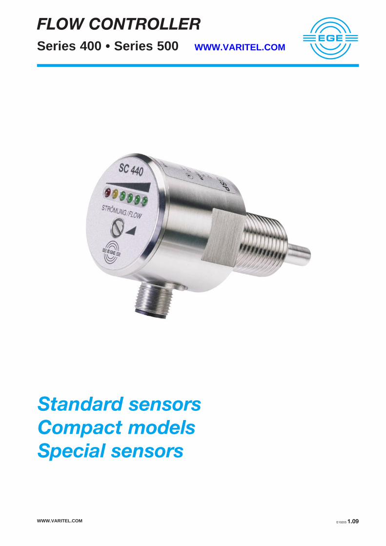
FLOW CONTROLLER
Series 400 • Series 500 WWW.VARITEL.COM
Standard sensors
Compact models
Special sensors
WWW.VARITEL.COM E10205 1.09
WWW.VARITEL.COM1.10 E10205
FLOW CONTROLLER
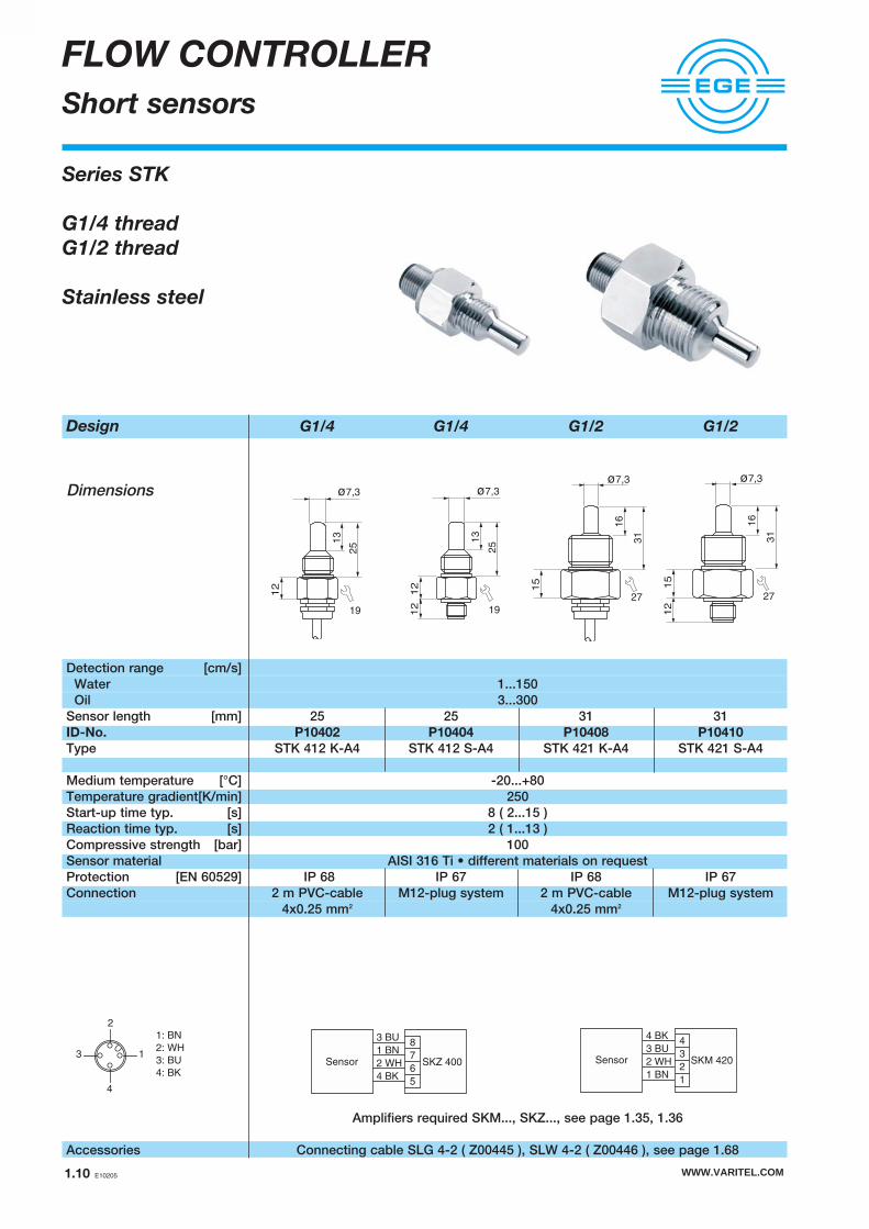
Short sensors
Design G1/4 G1/4 G1/2 G1/2
Dimensions
Detection range [cm/s]Water 1...150 Oil 3...300
Sensor length [mm] 25 25 31 31ID-No. P10402 P10404 P10408 P10410
Type STK 412 K-A4 STK 412 S-A4 STK 421 K-A4 STK 421 S-A4
Medium temperature [°C] -20...+80Temperature gradient[K/min] 250Start-up time typ. [s] 8 ( 2...15 )Reaction time typ. [s] 2 ( 1...13 )Compressive strength [bar] 100Sensor material AISI 316 Ti • different materials on requestProtection [EN 60529] IP 68 IP 67 IP 68 IP 67Connection 2 m PVC-cable M12-plug system 2 m PVC-cable M12-plug system
4x0.25 mm2 4x0.25 mm2
Amplifiers required SKM..., SKZ..., see page 1.35, 1.36
Accessories Connecting cable SLG 4-2 ( Z00445 ), SLW 4-2 ( Z00446 ), see page 1.68
251
3
ø7,3
12
19
251
3
ø7,3
12
1912
16
31
ø7,3
12
15
27
3 BU
1 BN
2 WH
4 BK
8
7
6
5
SKZ 400Sensor
4 BK
3 BU
2 WH
1 BN
4
3
2
1
SKM 420Sensor
4
3 1
2
1: BN
2: WH
3: BU
4: BK
Series STK
G1/4 thread
G1/2 thread
Stainless steel
16
31
ø7,3
15
27

Design G1/2 G1/2 G1/2 PTFE
Dimensions
Detection range [cm/s]Water 1...150 1...70 Oil 3...300 2...100
Sensor length [mm] 48 48 48ID-No. P10412 P10414 P10431
Type ST 421 K-A4 ST 421 S-A4 ST 421 K-F
Medium temperature [°C] -20...+80 -10...+70Temperature gradient[K/min] 250 1Start-up time typ. [s] 8 ( 2...15 ) 60 (40...100)Reaction time typ. [s] 2 ( 1...13 ) 30 (10...50)Compressive strength [bar] 100 5Sensor material AISI 316 Ti • different materials on request PTFEProtection [EN 60529] IP 68 IP 67 IP 68Connection 2 m PVC-cable M12-plug system 2 m FEP-cable
4x0.25 mm2 4x0.25 mm2
Amplifiers required SKM..., SKZ..., see page 1.35, 1.36
Accessories Connecting cable SLG 4-2 ( Z00445 ), SLW 4-2 ( Z00446 ), see page 1.68
FLOW CONTROLLER
Sensors
15
13
48
ø7,3
27
12
15
13
48
ø7,3
27
3 BU
1 BN
2 WH
4 BK
8
7
6
5
SKZ 400Sensor
4 BK
3 BU
2 WH
1 BN
4
3
2
1
SKM 420Sensor
4
3 1
2
1: BN
2: WH
3: BU
4: BK
15
13
48
ø7,7
27
Series ST
G1/2 thread
G3/4 thread
Stainless steel
PTFE-housing
WWW.VARITEL.COM E10205 1.11
WWW.VARITEL.COM1.12 E10205
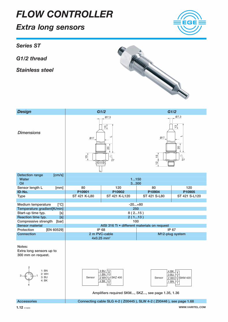
Design G1/2 G1/2
Dimensions
Detection range [cm/s]Water 1...150 Oil 3...300
Sensor length L [mm] 80 120 80 120ID-No. P10901 P10902 P10904 P10905
Type ST 421 K-L80 ST 421 K-L120 ST 421 S-L80 ST 421 S-L120
Medium temperature [°C] -20...+80Temperature gradient[K/min] 250Start-up time typ. [s] 8 ( 2...15 )Reaction time typ. [s] 2 ( 1...13 )Compressive strength [bar] 100Sensor material AISI 316 Ti • different materials on requestProtection [EN 60529] IP 68 IP 67Connection 2 m PVC-cable M12-plug system
4x0.25 mm2
Notes:Extra long sensors up to300 mm on request.
Amplifiers required SKM..., SKZ..., see page 1.35, 1.36
Accessories Connecting cable SLG 4-2 ( Z00445 ), SLW 4-2 ( Z00446 ), see page 1.68
FLOW CONTROLLER
Extra long sensors
Series ST
G1/2 thread
Stainless steel
ø17
15
13
L
ø7,3
27
20
ø17
15
13
L
ø7,3
27
20
12
3 BU
1 BN
2 WH
4 BK
8
7
6
5
SKZ 400Sensor
4 BK
3 BU
2 WH
1 BN
4
3
2
1
SKM 420Sensor
4
3 1
2
1: BN
2: WH
3: BU
4: BK

Design G1/4 G1/2 G1/2 G3/4
Dimensions
Detection range [cm/s]Water 1...150 Oil 3...300
Sensor length [mm] 25 31 48 48ID-No. P10435 P10436 P10437 P10438
Type STK 412 KH-A4 STK 421 KH-A4 ST 421 KH-A4 ST 431 KH-A4
Medium temperature [°C] +10...+120Temperature gradient[K/min] 250Start-up time typ. [s] 8 ( 2...15 )Reaction time typ. [s] 2 ( 1...13 )Compressive strength [bar] 100Sensor material AISI 316 Ti • different materials on requestProtection [EN 60529] IP 68Connection 2 m FEP-cable, 4x0.25 mm2
Notes: High temperature sensors may be used for temperature up to 120 °C. A short-time overload up to 135 °C is allowed; within this time the switching point is not specified. After returning back to temperatures below 120 °C the sensor will work properly again.
Amplifiers required SKM..., SKZ..., see page 1.35, 1.36
FLOW CONTROLLER
High temperature sensors
Series ST
G1/4 thread
G1/2 thread
G3/4 thread
Stainless steel
High temperature sensors 120 °C
15
13
48
ø7,3
32
15
13
48
ø7,3
27
3 BU
1 BN
2 WH
4 BK
8
7
6
5
SKZ 400Sensor
4 BK
3 BU
2 WH
1 BN
4
3
2
1
SKM 420Sensor
16
31
ø7,3
15
27
251
3
ø7,3
12
19
WWW.VARITEL.COM E10205 1.13

WWW.VARITEL.COM1.14 E10205
FLOW CONTROLLER
High temperature sensors
Design G1/2
Dimensions
Detection rangeFluids [cm/s] 1...300Air / gas [m/s] 1...40
Sensor length [mm] 31 48 80 ID-No. P11259 P11260 P11261
Type ST 521 KH ST 521/1 KH ST 521/2 KH
Medium temperature [°C] fluids +10...160 – air/gas +10...135Temperature gradient[K/min] fluids 250 – air/gas 20Start-up time [s] 5...20Reaction time [s] 2...20Compressive strength [bar] 60Protection [EN 60529] IP 67Sensor material AISI 316 Ti • different materials on requestConnection 2 m FEP-cable, 4x0.25 mm²
Amplifiers required SKM..., SKZ..., see page 1.35, 1.36
Series ST 521
G1/2 thread
High temperature sensors 160 °C
31
27
5120
ø17
48
68
27
20
ø17
3 BU
1 BN
2 WH
4 BK
8
7
6
5
SKZ 400Sensor
4 BK
3 BU
2 WH
1 BN
4
3
2
1
SKM 420Sensor
80
10
0
27
20
ø17

Design G1/2...HB2/HC22 G1/2...K-B3 G1/2...S-B3
Dimensions
Detection range [cm/s]Water 1...150 Oil 3...300
Sensor length [mm] 31 31 34 34ID-No. P10625 P11159 P10623 P10622
Type STA 421 K-HB2 STA 421 K-HC22 STA 421 K-B3 STA 421 S-B3Medium temperature [ºC] -20...+80 (+10...+120 on request)Temperature gradient [K/min] 250Reaction time [s] 1...15Compressive strength [bar] 100Sensor material Hastelloy B2 Hastelloy C22 Titanium / metal ceramicProtection [EN 60529] IP 68 IP 67Connection 2 m FEP-cable 4x0.25 mm2 M12-plug system
Amplifiers required SKM..., SKZ..., see page 1.35, 1.36
Accessories Connecting cable SLG 4-2 ( Z00445 ), SLW 4-2 ( Z00446 ), see page 1.68
WWW.VARITEL.COM E10205 1.15
FLOW CONTROLLER
Chemical sensors
4
3 1
2
1: BN
2: WH
3: BU
4: BK
G1/2
16
31
ø7,3
27
15
These sensors are made of titanium and arecoated with a metal-ceramic material layer.Coated sensors display chemical resistancepractically comparable to chemical charac-teristics of PTFE or Hastelloy. Unlike PTFEsensors, coated sensors display the sametemperature behaviour as stainless steelsensors, with high temperature gradients.The high surface hardness of the coatingprotects the sensor against abrasion, thusconsiderably increasing its durability. Theperfectly smooth surface virtually eliminatesdeposits.
G1/2
16
34
ø7,3
27
15
12
G1/2
16
34
ø7,3
27
15
3 BU
1 BN
2 WH
4 BK
8
7
6
5
SKZ 400Sensor
4 BK
3 BU
2 WH
1 BN
4
3
2
1
SKM 420Sensor
Series STA
G1/2 thread
Hastelloy B2/C22
Titanium / metal ceramic coated

FLOW CONTROLLER
Sensors for Food industry
Design Triclamp compact Triclamp ø 50.5 DIN 11851
Dimensions
Detection range [cm/s]Water 1...150Oil 3...300
OutputConnecting diameter DN ø 50.5 mm ø 50.5 mm DN 25 ID-No. P11156 P11060 P10632
Type SCB 450 GSP STB 450 K STC 425 K
Surface roughness [µm] < 0.8 < 0.8Supply voltage [V] 24 DC ± 20 % –Current consumption [mA] < 70 –Switching current [mA] 200 –Voltage drop [V] < 2 –Ambient temperature [°C] -20...+80 -20...+80Medium temperature [°C] -20...+80 (100)* +20...+120Temperature gradient [K/min] 250 250Start-up time [s] 8...15 2...15Reaction time typ. [s] 2 2Compressive strength [bar] 100 100Housing material 1.4404 1.4404 / PVDF (cable gland)Protection [EN 60529] IP 67 IP 68Connection M12-plug system 2 m FEP-cable, 4x0.25 mm2
Accessories SLG 3-2/3-5, SLW 3-2/3-5 Amplifiers: SKM..., SKZ..., see page 1.35, 1.36
L+
L-
(1) BN
(4) BK
(3) BU
2
4
13
ø50,5
3
ø13
2
55
107
ø7,3
55
ø7,3
ø50,5
ø13
32
Series SCB • STB • STC
Triclamp compact
Triclamp ø 50.5
DIN 11851
DC 24 V
PNP output
45
23
10
15°
ø44
ø31
ø 7,3
BK
BU
WH
BN
Sensor
WWW.VARITEL.COM1.16 E10205
*Note:The sensor may, for example during the cleaning process (CIP), be heated up to 100°Cfor a period of 10 minutes without being damaged. In this case, the switching point is not specified.

Design G1/4 G1/2 NPT1/2
Dimensions
Detection range [cm/s] Water 1...150 / Oil 3...300Output
Sensor length L [mm] 25 30 48 80 120 40Thread G1/4 G1/2 G1/2 G1/2 G1/2 NPT1/2ID-No. P11064 P10521 P10523 P10525 P10526 P11066
Type SC440/5-A4-GSP SC440-A4-GSP SC440/1-A4-GSP SC440/2-A4-GSP SC440/3-A4-GSP SC440/6-A4-GSP
Supply voltage [V] 24 DC ± 20%Current consumption [mA] 70 Switching current [mA] 400 ( 20 °C )Ambient temperature [°C] -20...+80Medium temperature [°C] -20...+80Temperature gradient[K/min] 250Start-up time typ. [s] 8 ( 2...15 )Reaction time typ. [s] 2 ( 1...13 )Compressive strength [bar] 100Sensor material AISI 316 Ti • different materials on requestHousing material Stainless steelDisplay flow LED-arrayProtection [EN 60529] IP 67Connection M12-plug system
Accessories Connecting cable SLG 3-2, SLG 3-5, SLW 3-2, SLW 3-5, see page 1.68
FLOW CONTROLLER
Compact models
Series SC 440
G1/4 thread
G1/2 thread
NPT1/2 thread
DC 24 V
PNP output
36
L
ø 7,3
13
36
ø 40
19
ø 7,3
36
L13
3636
ø 7,3
13
40
L+
L-
(1) BN
(4) BK
(3) BU
2
4
13
WWW.VARITEL.COM E10205 1.17

WWW.VARITEL.COM1.18 E10205
Design G1/2 • L= 31 mm G1/2 • L= 48 mm
Dimensions
Detection range [cm/s] Water 1...150 / Oil 3...300Output
Sensor length [mm] 31 31 48 48Thread G1/2 G1/2 G1/2 G1/2ID-No. P11241 P11161 P11228 P11162
Type SN 450-A4-GSP SN 450-A4-GSP-S SN 450/1-A4-GSP SN 450/1-A4-GSP-S
Supply voltage [V] 24 DC ± 20 %Current consumption [mA] 60Switching current [mA] 400Ambient temperature [°C] -20...+70Medium temperature [°C] -20...+80Temperature gradient[K/min] 250Start-up time typ. [s] 8 ( 2...15 )Reaction time typ. [s] 2 ( 1...13 )Compressive strength [bar] 100Sensor material AISI 316 Ti • different materials on requestHousing material PBTDisplay flow LED-arrayProtection [EN 60529] IP 67Connection 2 m PVC-cable M12-plug system 2 m PVC-cable M12-plug system
3x0.5 mm2 3x0.5 mm2
Accessories Connecting cable SLG 3-2, SLG 3-5, SLW 3-2, SLW 3-5, see page 1.68
FLOW CONTROLLER
Compact models
Series SN 450
G1/2 thread
DC 24 V
PNP output
89
44 31
G1
/2
15
ø7
,3
27
ø7
,3
G1
/2
108
44 48
29
27
50
78
12
L+
L-
(1) BN
(4) BK
(3) BU4
3 1
2
1: BN
2: -
3: BU
4: BK

4
3 1
2
1: BN
2: WH
3: BU
4: BK
BN
GYBKWH
BUL-
L+(1) BN
(3) BUL-
L+
(2) WH
(4) BK
BN
GYBKWH
BUL-
L+(1) BN
(3) BUL-
L+
(2) WH
(4) BK
Design G1/2 • L= 31 mm G1/2 • L= 48 mm
Dimensions
Detection range [cm/s] Water 1...150 / Oil 3...300Output
Sensor length [mm] 31 31 48 48Thread G1/2 G1/2 G1/2 G1/2ID-No. P11115 P11116 P11078 P11086
Type SN 450-A4-GR SN 450-A4-GRS SN 450/1-A4-GR SN 450/1-A4-GRS
Supply voltage [V] 24 DC ± 20%Current consumption [mA] 80Switching voltage [V] 250 AC / 60 DCSwitching current [mA] 4 A AC / 4 A DC 2 A AC / 2 A DC 4 A AC / 4 A DC 2 A AC / 2 A DCSwitching power max. 1000 VA / 60 W 500 VA / 50 W 1000 VA / 60 W 500 VA / 50 WAmbient temperature [°C] -20...+70Medium temperature [°C] -20...+80Temperature gradient[K/min] 250Start-up time typ. [s] 8 ( 2...15 )Reaction time typ. [s] 2 ( 1...13 )Compressive strength [bar] 100Sensor material AISI 316 Ti • different materials on requestHousing material PBTDisplay flow LED-arrayProtection [EN 60529] IP 67Connection 2 m PVC-cable M12-plug system 2 m PVC-cable M12-plug system
5x0.5 mm2 5x0.5 mm2
Accessories Connecting cable SLG 4-2, SLG 4-5, SLW 4-2, SLW 4-5, see page 1.68
FLOW CONTROLLER
Compact models
Series SN 450
G1/2 thread
DC 24 V
Relay output
89
44 31
G1
/2
15
ø7
,3
27
ø7
,3
G1
/2
108
44 48
29
27
WWW.VARITEL.COM E10205 1.19
5078
12

WWW.VARITEL.COM1.20 E10205
Design G1/2 • L= 31 mm G1/2 • L= 48 mm
Dimensions
Detection range [cm/s] Water 1...150 / Oil 3...300Output
Sensor length [mm] 31 31 48 48Thread G1/2 G1/2 G1/2 G1/2
ID-No. P11113 P11114 P11074 P11076
Type SN 450-A4-WR1 SN 450-A4-WR2 SN 450/1-A4-WR1 SN 450/1-A4-WR2
Supply voltage [V] 115 AC ± 15% 230 AC ± 15% 115 AC ± 15% 230 AC ± 15%Current consumption [mA] 60 30 60 30 Switching voltage [V] 250 AC / 60 DCSwitching current [mA] 4 A AC / 4 A DCSwitching power max. 1000 VA / 60 WAmbient temperature [°C] -20...+70Medium temperature [°C] -20...+80Temperature gradient[K/min] 250Start-up time typ. [s] 8 ( 2...15 )Reaction time typ. [s] 2 ( 1...13 )Compressive strength [bar] 100Sensor material AISI 316 Ti • different materials on requestHousing material PBTDisplay flow LED-arrayProtection [EN 60529] IP 67Connection 2 m PVC-cable, 5x0.5 mm2
FLOW CONTROLLER
Compact models
Series SN 450
G1/2 thread
AC 230 V • 115 V
Relay output
5078
89
44 31
G1
/2
15
ø7
,3
27
ø7
,3
G1
/2
108
44 48
29
27
BN
GYBKWH
BUN
L1

Design G1/2 • L= 80 mm G1/2 • L= 120 mm
Dimensions
Detection range [cm/s] Water 1...150 / Oil 3...300Output
Sensor length L [mm] 80 80 80 120 120 120Thread G1/2 G1/2 G1/2 G1/2 G1/2 G1/2ID-No. P11079 P11080 P11081 P11082 P11083 P11084
Type SN450/2-A4-WR1 SN450/2-A4-WR2 SN450/2-A4-GR SN450/3-A4-WR1 SN450/3-A4-WR2 SN450/3-A4-GR
Supply voltage [V] 115 AC±15% 230 AC±15% 24 DC±20% 115 AC±15% 230 AC±15% 24 DC±20%Current consumption [mA] 60 30 80 60 30 80Switching voltage [V] 250 AC / 60 DCSwitching current [mA] 4 A AC / 4 A DCSwitching power max. 1000 VA / 60 WAmbient temperature [°C] -20...+70Medium temperature [°C] -20...+80Temperature gradient[K/min] 250Start-up time typ. [s] 8 ( 2...15 )Reaction time typ. [s] 2 ( 1...13 )Compressive strength [bar] 100Sensor material AISI 316 Ti • different materials on requestHousing material PBTDisplay flow LED-arrayProtection [EN 60529] IP 67Connection 2 m PVC-cable, 5x0.5 mm2
FLOW CONTROLLER
Compact models
Series SN 450
G1/2 thread
AC 230 V • AC 115 V
DC 24 V
Relay output
44
G1/2
L
ø 7
,3
L+59
27
20
ø17
BN
GYBKWH
BUN
L1BN
GYBKWH
BUL-
L+
WWW.VARITEL.COM E10205 1.21
50
78
WWW.VARITEL.COM1.22 E10205
FLOW CONTROLLER
Compact models
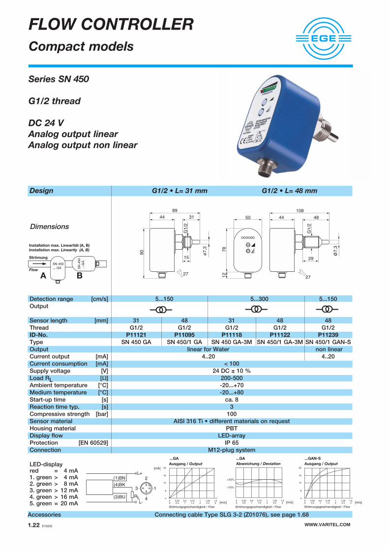
Design G1/2 • L= 31 mm G1/2 • L= 48 mm
Dimensions
Detection range [cm/s] 5...150 5...300 5...150Output
Sensor length [mm] 31 48 31 48 48Thread G1/2 G1/2 G1/2 G1/2 G1/2ID-No. P11121 P11095 P11118 P11122 P11239
Type SN 450 GA SN 450/1 GA SN 450 GA-3M SN 450/1 GA-3M SN 450/1 GAN-SOutput linear for Water non linearCurrent output [mA] 4..20 4..20Current consumption [mA] < 100Supply voltage [V] 24 DC ± 10 %Load RL [Ω] 200-500Ambient temperature [°C] -20...+70Medium temperature [°C] -20...+80Start-up time [s] ca. 8Reaction time typ. [s] 3Compressive strength [bar] 100Sensor material AISI 316 Ti • different materials on requestHousing material PBTDisplay flow LED-arrayProtection [EN 60529] IP 65Connection M12-plug system
LED-display
Accessories Connecting cable Type SLG 3-2 (Z01076), see page 1.68
RL
L+
L-
(1)BN
(4)BK
(3)BU
2
4
13
8944 31
90
15
ø7,3
27
G1/2
Installation max. Linearität (A, B)
Installation max. Linearity (A, B)
Strömung
Flow
red = 4 mA1. green > 4 mA2. green > 8 mA3. green > 12 mA4. green > 16 mA5. green = 20 mA
Series SN 450
G1/2 thread
DC 24 V
Analog output linear
Analog output non linear
50
78
12
27
44
29
48
ø7,3
G1/2
108
Ausgang / Output
Strömungsgeschwindigkeit / Flow
[m/s]
Ausgang / Output
Strömungsgeschwindigkeit / Flow
[mA]
[m/s]
Strömungsgeschwindigkeit / Flow
Abweichung / Deviation
[m/s]
...GA ...GA ...GAN-S

Design G1/2 • L= 31 mm
Dimensions
Detection range [cm/s] Water 1...150 / Oil 3...300Output
Sensor length [mm] 31Thread G1/2ID-No. P11264
Type SN 450 GPPSupply voltage [V] 24 DC±20%Current consumption [mA] 100Switching current [mA] 200Ambient temperature [°C] -20...+60Medium temperature [°C] -20...+80Temperature gradient[K/min] 250Start-up time typ. [s] 1...15Compressive strength [bar] 100Sensor material AISI 316 Ti • different materials on requestHousing material PBTDisplay flow LED-arrayProtection [EN 60529] IP 67Connection M12-plug system
Accessories Connecting cable Type SLG 4-2 (Z00445), see page 1.68
FLOW CONTROLLER
Compact models
Series SN 450
G1/2 thread
DC 24 V
PNP output
2 independent switching points
50
78
12
WWW.VARITEL.COM E10205 1.23
8944 31
90
15
ø7,3
27
G1/2
4
3 1
2
1: BN
2: WH
3: BU
4: BK
(2) WH
L+
L-
(1) BN
(4) BK
(3) BU
WWW.VARITEL.COM1.24 E10205
FLOW CONTROLLER
Compact models
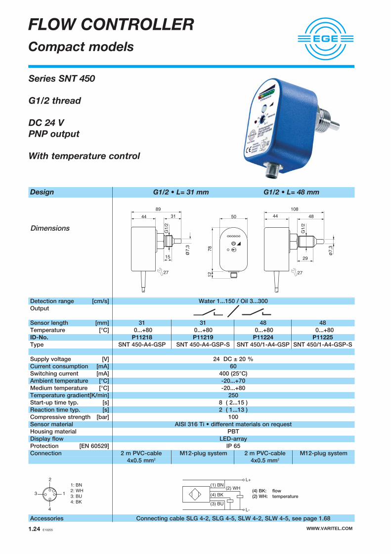
Design G1/2 • L= 31 mm G1/2 • L= 48 mm
Dimensions
Detection range [cm/s] Water 1...150 / Oil 3...300Output
Sensor length [mm] 31 31 48 48Temperature [°C] 0...+80 0...+80 0...+80 0...+80ID-No. P11218 P11219 P11224 P11225
Type SNT 450-A4-GSP SNT 450-A4-GSP-S SNT 450/1-A4-GSP SNT 450/1-A4-GSP-S
Supply voltage [V] 24 DC ± 20 %Current consumption [mA] 60Switching current [mA] 400 (25°C) Ambient temperature [°C] -20...+70Medium temperature [°C] -20...+80Temperature gradient[K/min] 250Start-up time typ. [s] 8 ( 2...15 )Reaction time typ. [s] 2 ( 1...13 )Compressive strength [bar] 100Sensor material AISI 316 Ti • different materials on requestHousing material PBTDisplay flow LED-arrayProtection [EN 60529] IP 65Connection 2 m PVC-cable M12-plug system 2 m PVC-cable M12-plug system
4x0.5 mm2 4x0.5 mm2
Accessories Connecting cable SLG 4-2, SLG 4-5, SLW 4-2, SLW 4-5, see page 1.68
Series SNT 450
G1/2 thread
DC 24 V
PNP output
With temperature control
89
44 31
G1
/2
15
ø7
,3
27
ø7
,3
G1
/2
108
44 48
29
27
4
3 1
2
1: BN
2: WH
3: BU
4: BK
50
78
12
(4) BK: flow(2) WH: temperature
(2) WH
L+
L-
(1) BN
(4) BK
(3) BU

Design G1/2 • L= 31 mm G1/2 • L= 48 mm
Dimensions
Detection range [cm/s] Water 1...150 / Oil 3...300Output
Sensor length [mm] 31 31 48 48Temperature [°C] 0...+80 0...+80 0...+80 0...+80ID-No. P11216 P11217 P11222 P11223
Type SNT 450-A4-GR SNT 450-A4-GR-S SNT 450/1-A4-GR SNT 450/1-A4-GR-S
Supply voltage [V] 24 DC±20% 24 DC±20% 24 DC±20% 24 DC±20%Current consumption [mA] 80 80 80 80Switching voltage [V] 250AC / 60DC 30AC / 36DC 250AC / 60DC 30AC / 36DCSwitching current [mA] 2A AC / 2A DC 1A AC / 1A DC 2A AC / 2A DC 1A AC / 1A DCSwitching power max. 500 VA / 60 W - 500 VA / 60 W -Ambient temperature [°C] -20...+70Medium temperature [°C] -20...+80Temperature gradient[K/min] 250Start-up time typ. [s] 8 ( 2...15 )Reaction time typ. [s] 2 ( 1...13 )Compressive strength [bar] 100Sensor material AISI 316 Ti • different materials on requestHousing material PBTDisplay flow LED-arrayProtection [EN 60529] IP 65Connection 2 m PVC-cable M12-plug system 2 m PVC-cable M12-plug system
6x0.5 mm2 6x0.5 mm2
Accessories Connecting cable SLG 5-2, SLW 5-2, see page 1.68
FLOW CONTROLLER
Compact models
89
44 31
G1
/2
15
ø7
,3
27
ø7
,3
G1
/2
108
44 48
29
27
Series SNT 450
G1/2 thread
DC 24 V
Relay output
With temperature control
4
3 1
2
1: BN
2: WH
3: BU
4: BK
5: GY5
Fix
ed
ca
ble
Plu
g
WWW.VARITEL.COM E10205 1.25
5078
12
BN
BUL-
L+
PK Temperatur
GN flowGY Strömung
WH temperature
(1) BN
(2) WH
(4) BK Strömung
(3) BU
(5) GY
L+
L-
flowTemperaturtemperature

WWW.VARITEL.COM1.26 E10205
FLOW CONTROLLER
Compact models
Design G1/2 • L= 31 mm G1/2 • L= 48 mm
Dimensions
Detection range [cm/s] Water 1...150 / Oil 3...300Output
Sensor length [mm] 31 48 31 48Temperature [°C] 0...+80 0...+80 0...+80 0...+80ID-No. P11214 P11215 P11220 P11221
Type SNT 450-A4-WR1 SNT 450-A4-WR2 SNT 450/1-A4-WR1 SNT 450/1-A4-WR2
Supply voltage [V] 115 AC±15% 230 AC±15% 115 AC±15% 230 AC±15%Current consumption [mA] 60 30 60 30Switching voltage [V] 250 AC / 60 DCSwitching current [A] 2 AC / 2 DCSwitching power max. 500 VA / 60 WAmbient temperature [°C] -20...+70Medium temperature [°C] -20...+80Temperature gradient[K/min] 250Start-up time typ. [s] 8 ( 2...15 )Reaction time typ. [s] 2 ( 1...13 )Compressive strength [bar] 100Sensor material AISI 316 Ti • different materials on requestHousing material PBTDisplay flow LED-arrayProtection [EN 60529] IP 65Connection 2 m PVC-cable, 6x0.5 mm2
89
44 31
G1
/2
15
ø7
,3
27
ø7
,3
G1
/2
108
44 48
29
27
Series SNT 450
G1/2 thread
AC 230 V • 115 V
Relay output
With temperature control
5078
BN
BUN
L1
PK Temperatur
GN flowGY Strömung
WH temperature

Design G1/2 • L= 48 mm
Dimensions
Detection range [cm/s] Water 1...150 / Oil 3...300Output
ID-No. P11233 P11234 P11231
Type SN 450/1GR-VA SN 450/1GR-VE SN 450/1WR2-VA
Turn on delay [s] - 0...25 -Turn off delay [s] 0...25 - 0...25Supply voltage [V] 24 DC±20% 24 DC±20% 230 AC±15%Current consumption [mA] 80 80 30Switching voltage [V] 250AC / 60DCSwitching current [A] 2 AC / 2 DCSwitching power max. 500 VA / 60 WAmbient temperature [°C] -20...+70Medium temperature [°C] -20...+80Temperature gradient[K/min] 250Start-up time typ. [s] 8 ( 2...15 )Reaction time typ. [s] 2 ( 1...13 )Compressive strength [bar] 100Sensor material AISI 316 Ti • different materials on requestHousing material PBTDisplay flow LED-arrayProtection [EN 60529] IP 65Connection 2 m PVC-cable, 4x0.5 mm2 2 m PVC-cable, 5x0.5 mm2
FLOW CONTROLLER
Compact models
ø7
,3
G1
/2
108
44 48
29
27
Series SN 450
G1/2 thread
AC 230 V
DC 24 V
Relay output
Turn on/off delay
WWW.VARITEL.COM E10205 1.27
(1) BN
(3) BUL-
L+
(2) WH
(4) BK
50
78
BN
GYBKWH
BUN
L1

WWW.VARITEL.COM1.28 E10205
FLOW CONTROLLER
Inline-Compact
Design G1/4 • Ø 4 mm G1/4 • Ø 9 mm
Dimensions
Detection range [l/min] 0.001...1 0.01...6Working range [l/min] 0.015...1 0.1...6Inner diameter d [mm] 4 9Maximum flow [I/h] 300 1800Output
PNP relay 4-20mA PNP relay 4-20mAID-No. P11247 P11271 P11249 P11248 P11273 P11250
Type SDN 504 GSP SDN 504 GR SDN 504 GA SDN 510 GSP SDN 510 GR SDN 510 GASwitching current [mA] 200 1000 - 200 1000 -Switching voltage [V] - 30AC/36DC - - 30AC/36DC -Load RL [Ω] - - 200...500 - - 200...500
Supply voltage [V] 24 DC±10%Current consumption [mA] < 50Ambient temperature [°C] 0...+60Medium temperature [°C] 0...+80Temperature gradient[K/min] 400Start-up time typ. [s] 5...15Reaction time typ. [s] 0.5...1Compressive strength [bar] 20Display flow LED-arrayMaterial housing: PBT sensor: AISI 316 Ti Protection [EN 60529] IP 67Connection M12-plug system
Accessories Connecting cable Type SLG, SLW, SBG, SBW, see page 1.68
RL
L+(1) BN
(4) BK
(3) BUL-
2
4
13
L+(1) BN
(4) BK
(3) BUL-
2
4
13
Series SDN
G1/4 thread • ø 4 mm
G1/4 thread • ø 9 mm
DC 24 V
PNP output
Relay output
Analog output
(1) BN
(3) BUL-
L+
(2) WH
(4) BK
27
ød
25
45
112
G1/4
505
9
30
67
19

Design G1/2 • Ø 15 mm G3/4 • Ø 19 mm
Dimensions
Detection range [l/min] 2...25 3...40Working range [l/min] 3...20 4...30Inner diameter d [mm] 15 19Maximum flow [l/h] 4000 7500Output
PNP relay 4-20mA PNP relay 4-20mAID-No. P11284 P11288 P11286 P11285 P11289 P11287
Type SDN 515 GSP SDN 515 GR SDN 515 GA SDN 520 GSP SDN 520 GR SDN 520 GASwitching current [mA] 200 1000 - 200 1000 -Switching voltage [V] - 30AC/36DC - - 30AC/36DC -Load RL [Ω] - - 200...500 - - 200...500Supply voltage [V] 24 DC±10%Current consumption [mA] < 60Ambient temperature [°C] 0...+60Medium temperature [°C] 0...+80Temperature gradient[K/min] 400Start-up time typ. [s] 5...15Reaction time typ. [s] 0.5...3Compressive strength [bar] 20Display flow LED-arrayMaterial housing: PBT sensor: AISI 316 Ti / FPMProtection [EN 60529] IP 67Connection M12-plug system
Accessories Connecting cable Type SLG, SLW, SBG, SBW, see page 1.68
FLOW CONTROLLER
Inline-Compact
G1/2
118
50
30
45
107,5
77,5
27
ød
30
38
G3/4
118
30
50
45
79
118
WWW.VARITEL.COM E10205 1.29
RL
L+(1) BN
(4) BK
(3) BUL-
2
4
13
L+(1) BN
(4) BK
(3) BUL-
2
4
13
Series SDN
G1/2 thread • ø 15 mm
G3/4 thread • ø 19 mm
DC 24 V
PNP output
Relay output
Analog output
(1) BN
(3) BUL-
L+
(2) WH
(4) BK

WWW.VARITEL.COM1.30 E10205
FLOW CONTROLLER
Inline-Compact • Micro pulses detection
Design G1/4 • Ø 4 mm
Dimensions
Detection range [l/min] from 0.02 ml/100 msWorking range [l/min] from 0.04 ml/100 msInner diameter [mm] 4Maximum flow [I/h] 300Output Detects increasing in flow Switch-off delay (Hold)
PNP 0.5...10sID-No. P11256
Type SDN 504 GSP-DYNSwitching current [mA] 200Switching voltage [V] -Switching power max. -Load RL [Ω] -Supply voltage [V] 24 DC±10%Current consumption [mA] < 50Ambient temperature [°C] 0...+60Medium temperature [°C] -20...+80Start-up time typ. [s] 5...15Reaction time typ. [s] < 0.1 Compressive strength [bar] 20Display flow LEDMaterial housing: PBT sensor: AISI 316 TiProtection [EN 60529] IP 67Connection M12-plug system
Accessories Connecting cable Type SLG, SLW, SBG, SBW, see page 1.68
Series SDN
G1/4 thread • ø 4 mm
DC 24 V
PNP output
Detection of Micro flow pulses
Switch-off delay 0.5...10 s
L+(1) BN
(4) BK
(3) BUL-
2
4
13
27
ø4
25
45112
G1/4
505
9
30
67
19

WWW.VARITEL.COM E10205 1.31
Design Hose connection Ø 4 mm
Dimensions
Detection range [ml/min] 0.1...500Working range [ml/min] 1...200Inner diameter [mm] 3.6Maximum flow [I/h] 100Output
PNP relay 4...20mA, non linearID-No. P11265 P11277 P11266
Type SDN 503 GSP SDN 503 GR SDN 503 GASwitching current [mA] 200 1000 -Switching voltage [V] - 30AC / 36DC -Load RL [W] - - 200-500Supply voltage [V] 24 DC±10%Current consumption [mA] < 50Ambient temperature [°C] 0...+60Medium temperature [°C] 0...+60Temperature gradient[K/min] 400Start-up time [s] 5...20Reaction time typ. [s] 0.5...3Compressive strength [bar] 1Display flow LED-arrayMaterial housing: PBT sensor: AISI 316 TiProtection [EN 60529] IP 67Connection M12-plug system
Accessories Connecting cable Type SLG, SLW, SBG, SBW, see page 1.68
FLOW CONTROLLER
Inline-Compact • Micro flow • Laboratory
Series SDN
Hose connection ø 4 mm
DC 24 V
PNP output
Relay output
Analog output
Fast reaction time - high sensitivity
27
ø3,6
25
45
112
5059
30
6840
125
Strömung / flow
ø4
RL
L+(1) BN
(4) BK
(3) BUL-
2
4
13
L+(1) BN
(4) BK
(3) BUL-
2
4
13
(1) BN
(3) BUL-
L+
(2) WH
(4) BK

Design Triclamp Ø 10 mm
Dimensions
Detection range [l/min] 0.01...6Working range [l/min] 0.1...6Inner diameter [mm] 10Maximum flow [l/h] 1800Output
PNP relay 4...20mA, non linearID-No. P11258 P11279 P11280
Type SDB 510 GSP SDB 510 GR SDB 510 GASwitching current [mA] 200 1000 -Switching voltage [V] - 30AC / 36DC -Load RL [Ω] - - 200...500Supply voltage [V] 24 DC±10%Current consumption [mA] < 50Ambient temperature [°C] 0...+60Medium temperature [°C] -20...+80 -20...+80 -20...+60Temperature gradient[K/min] 400Start-up time typ. [s] 5...15Reaction time typ. [s] 0.5...1Compressive strength [bar] 20Display flow LED-arrayMaterial housing: PBT sensor: 1.4404Protection [EN 60529] IP 67Connection M12-plug system
Accessories Connecting cable Type SLG, SLW, SBG, SBW, see page 1.68
FLOW CONTROLLER
Inline-Compact • Food • Pharma
112
5059
67
4530
DIN /
DN10
27
ø10
25
34
Series SDN
Triclamp connection ø 34 mm
Inner diameter ø 10 mm
DC 24 V
PNP output
Relay output
Analog output
RL
L+(1) BN
(4) BK
(3) BUL-
2
4
13
L+(1) BN
(4) BK
(3) BUL-
2
4
13
WWW.VARITEL.COM1.32 E10205
(1) BN
(3) BUL-
L+
(2) WH
(4) BK

WWW.VARITEL.COM E10205 1.33
Design G1/4 • Ø 6 mm
Dimensions
Detection range [l/min] 0.005...3Working range [l/min] 0.02...3Inner diameter [mm] 6Maximum flow [l/h] 300Output
PNP relay 4...20mA, non linearID-No. P11262 P11275 P11263
Type SDN 506 GSP-CER SDN 506 GR-CER SDN 506 GA-CERSwitching current [mA] 200 1000 -Switching voltage [V] - 30AC / 36DC -Load RL [Ω] - - 200...500Supply voltage [V] 24 DC±10%Current consumption [mA] < 50Ambient temperature [°C] 0...+60Medium temperature [°C] 0...+60Temperature gradient[K/min] 400Start-up time typ. [s] 5...15Reaction time typ. [s] 0.5...3Compressive strength [bar] 5Display flow LED-arrayMaterial housing: PBT sensor: AL2O3 / PTFE / FPM (different materials on request)Protection [EN 60529] IP 67Connection M12-plug system
Accessories Connecting cable Type SLG, SLW, SBG, SBW, see page 1.68
FLOW CONTROLLER
Inline-Compact • Ceramic • Chemical
Series SDN
G1/4 thread • ø 6 mm
DC 24 V
PNP output
Relay output
Analog output
Ceramic measuring cell • Metal free
45
G1/4
505
9
30
70
11
2
27
ø6
25
RL
L+(1) BN
(4) BK
(3) BUL-
2
4
13
L+(1) BN
(4) BK
(3) BUL-
2
4
13
(1) BN
(3) BUL-
L+
(2) WH
(4) BK

Design G1/4 • Ø 4 mm G1/4 • Ø 9 mm
Dimensions
Detection range [l/min] 0.001...1 0.01...6Working range [l/min] 0.01...0.8 0.2...6Inner diameter [mm] 4 9Maximum flow [l/h] 300 1800
ID-No. P11251 P11252
Type SD 504 S SD 510 S
Ambient temperature [°C] -20...+70Medium temperature [°C] 0...+80Temperature gradient[K/min] 400Start-up time [s] 5Reaction time typ. [s] 1Compressive strength [bar] 20Display flow -Material housing: PBT sensor: AISI 316 TiProtection [EN 60529] IP 67Connection M12-plug system
Accessories Connecting cable Type SLG 4-2 (Z00445), see page 1.68
G1/4
67
ø4
15
40
M12 x 1
29
19
G1/4
67
ø9
15
40
M12 x 1
29
19
Series SD
G1/4 thread • ø 4 mm
G1/4 thread • ø 9 mm
FLOW CONTROLLER
Inline-Sensors
4
3 1
2
1: BN
2: WH
3: BU
4: BK
3 BU
1 BN
2 WH
4 BK
8
7
6
5
SKZ 400Sensor
4 BK
3 BU
2 WH
1 BN
4
3
2
1
SKM 420Sensor
Amplifiers required SKM..., SKZ..., see page 1.35, 1.36
WWW.VARITEL.COM1.34 E10205
27
ød

Design SKM 420 GR SKM 421 GR SKM 420 GA
Dimensions
ID-No. P10530 P11067 P10820
Type SKM 420 GR SKM 421 GR (air flow) SKM 420 GA
Supply voltage [V] 24 DC ± 20% 24 DC ± 10%Output relay / NO analog 4...20mASwitching voltage [V] 230 AC / 250 DC -Switching current [A] 1 AC / 1 DC -Switching power max. 125 VA / 60 W -Load RL [Ω] - 50...500Ambient temperature [°C] -20...+60 20...+60Protection [EN 60529]
Terminal IP 20 IP 20Housing IP 40 IP 40
FLOW CONTROLLER
Amplifiers
Series SKM
DC 24 V
Analog output
Relay output
LED-Display
58 17,5
90
mA
SKM 420 GA
20
4
>4
EGE
4 BK
3 BU
2 WH
1 BNFlow
–+
SKM 420 / SKM 421 GR
Sensor
8
7
6
5
4
3
2
1Strömung
4 BK
3 BU
2 WH
1 BN Flow
–
–4…20 mA
+
SKM 420 GA
Sensor
8
7
6
5
4
3
2
1
Strömung
20
16
12
8
40 20 40
Sensor range [%]
Outp
ut curr
ent [m
A]
60 80 100
WWW.VARITEL.COM E10205 1.35
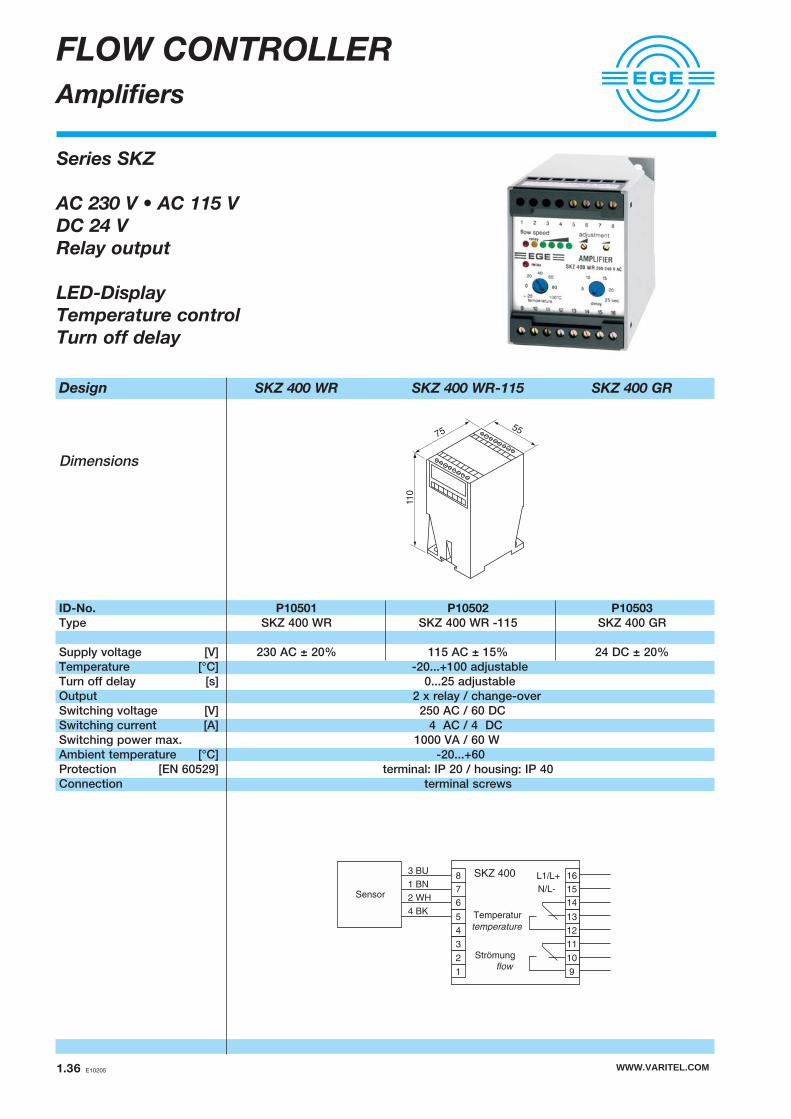
Design SKZ 400 WR SKZ 400 WR-115 SKZ 400 GR
Dimensions
ID-No. P10501 P10502 P10503
Type SKZ 400 WR SKZ 400 WR -115 SKZ 400 GR
Supply voltage [V] 230 AC ± 20% 115 AC ± 15% 24 DC ± 20%Temperature [°C] -20...+100 adjustableTurn off delay [s] 0...25 adjustableOutput 2 x relay / change-overSwitching voltage [V] 250 AC / 60 DCSwitching current [A] 4 AC / 4 DCSwitching power max. 1000 VA / 60 WAmbient temperature [°C] -20...+60Protection [EN 60529] terminal: IP 20 / housing: IP 40Connection terminal screws
FLOW CONTROLLER
Amplifiers
Series SKZ
AC 230 V • AC 115 V
DC 24 V
Relay output
LED-Display
Temperature control
Turn off delay
3 BU
1 BN
2 WH
4 BK
L1/L+
N/L-
SKZ 400
Sensor
16
15
14
13
12
11
10
9
8
7
6
5
4
3
2
1
Temperatur
Strömung
flow
temperature
WWW.VARITEL.COM1.36 E10205
110
7555

AIR FLOW CONTROLLER
Series 400 • Series 500 WWW.VARITEL.COM
Air flow controllers
Compact models
Sensors
WWW.VARITEL.COM E10205 1.37

Design G1/2
Dimensions
Detection range [m/s] 0.5...30Sensor length [mm] 48 48ID-No. P11100 P11101
Type LTZ 421 K-A2 LTZ 421 S-A2Medium temperature [°C] -20...+80Temperature gradient[K/min] 20Start-up time typ. [s] 10...90Reaction time typ. [s] 2...30Switching-off time [s] 5...30Compressive strength [bar] 30Sensor material AISI 303 • different materials on requestProtection [EN 60529] IP 68 IP 67Connection 2 m PVC-cable, 4x0.25 mm2 M12-plug system
Amplifiers required SKZ..., SKM..., see page 1.35, 1.36
Accessories Connecting cable SLG 4-2, SLG 4-5, SLW 4-2, SLW 4-5, see page 1.68
AIR FLOW CONTROLLER
Sensors
Series LTZ
G1/2 thread
Stainless steel
4
3 1
2
1: BN
2: WH
3: BU
4: BK
WWW.VARITEL.COM1.38 E10205
48
15
29
G1/2
ø6
9,5
2748
15
29
G1/2
ø6
9,5
27
12
3 BU
1 BN
2 WH
4 BK
8
7
6
5
SKZ 400Sensor
4 BK
3 BU
2 WH
1 BN
4
3
2
1
SKM 420Sensor

WWW.VARITEL.COM E10205 1.39
AIR FLOW CONTROLLER
Compact model
Series LN • LG
DC 24 V
PNP output
Analog output
LED-Display
Detection range 0.5...15 m/s
Design ø 20 mm M18x1 M22x1
Dimensions
Detection range [m/s] 0.5...15Output
PNP 4...20 mA PNP 4...20 mA PNPID.No. P11096 P11097 P11237 P11240 P11163
Type LN 520 GSP LN 520 GA LG 518 GSP LG 518 GA LG 522 GSP
Switching current [mA] 200 – 200 – 200Load RL [Ω] – 200-500 – 200-500 –Supply voltage [V] 24 DC ± 20%Current consumption [mA] 70Ambient temperature [ºC] -20...+70Temperature gradient [K/min] 200Start-up time [s] 20...40Reaction time typ. [s] 2 3 2 3 2 Housing material PBT PBT PBT / Ms-Ni PBT / Ms-Ni PBT / Ms-NiDisplay flow LEDProtection [EN 60529] IP 67Connection 2 m PVC-cable, 3x0.5 mm²
Accessories Flange ø20 (Z01106), see page 1.71
L+
L-
(1) BN
(4) BK
(3) BU
L+(1) BN
(4) BK
(3) BUL-
RL
76
Pot.
LED
80
60
Pot.
LED
24 2776
55
Pot.
LED
4
8
12
16
20
0 20 40 60 80
mA
100%

Design Ø 20 M38x1.5
Dimensions
Detection range [m/s] 2...25 1..25Output
ID-No. E10152 E10146
Type LN 020 WS LG 038 WSSupply voltage [V] 230 AC ± 10 %Current consumption [mA] 15Switching voltage [V] 230 ACSwitching current [mA] 400 Switching power max. [VA] 80Ambient temperature [°C] -20...+70Start-up time typ. [s] 20 4Reaction time typ. [s] 6 2Switching-off time [s] 7 2Housing material ABS / PBT Ms-NiProtection [EN 60529] IP 67
Notice:The thread of the sensor canresist a pressure up to 3 bar.
Accessories Flange ø20 (Z01106), see page 1.71
AIR FLOW CONTROLLER
Compact model
Series LN • LG
AC 230 V
LED-Display
86
Poti LED
3
Poti LED
Metall
90
14
70
YE/GN
L1
N
BK
BN
BU
WWW.VARITEL.COM1.40 E10205

WWW.VARITEL.COM E10205 1.41
AIR FLOW CONTROLLER
Compact model
Series LD 550
Hose connection
DC 24 V
PNP output
Fast reaction time
Design DC PNP • G1/4
Dimensions
Detection range [m/s] 0.3...15Output
ID-No. P11236
Type LD 550 GSP
Supply voltage [V] 24 DC ± 15%Current consumption [mA] 100Switching current [mA] 200Voltage drop [V] 2Load RL [Ω] –Ambient temperature [°C] -20...+70Temperature gradient[K/min] 400Start-up time [s] 15Reaction time typ. [s] 0.3Compressive strength [bar] 10Material AISI 303 / PBTProtection [EN 60529] IP 67Display flow LED-arrayConnection M12-plug system
Notice:Only dry and cleanair should be used.
Accessories Connecting cable SLG 3-2, SLG 3-5, SLW 3-2, SLW 3-5, see page 1.68
G1/4
60
44
27
78 12
M6 M622
50
G1/4
13
L+
L-
(1) BN
(4) BK
(3) BU
2
4
13

Design DC Analog • G1/2
Dimensions
Detection range [m/s] 0.5...30Output
ID-No. P11110 P11111
Type LNZ 450 GA-K LNZ 450 GA-S
Supply voltage [V] 24 DC ± 15 %Current consumption [mA] 80Current output [mA] 4...20Load RL [Ω] 200-500Ambient temperature [°C] -20...+70Medium temperature [°C] -20...+80Temperature gradient[K/min] 20Start-up time typ. [s] 20...90Reaction time typ. [s] 4...30Compressive strength [bar] 30Sensor material 1.4305 Display flow LED-arrayProtection [EN 60529] IP 67Connection 2 m PVC-cable, 3x0.5 mm2 M12-plug system
Accessories Connecting cable SLG 3-2, SLG 3-5, SLW 3-2, SLW 3-5, see page 1.68
AIR FLOW CONTROLLER
Compact model with analog output
Series LNZ
G1/2 thread
DC 24 V
Analog output
WWW.VARITEL.COM1.42 E10205
G1/2
ø1
7
44
108
32
48
9,5
27
50
78
12
RL
L+(1) BN
(4) BK
(3) BUL-
2
4
13
4
8
12
16
20
0 20 40 60 80
mA
100%

Design AC • G1/2 DC Relay • G1/2
Dimensions
Detection range [m/s] 0.5...30 0.5...30 0.5...30Output
ID-No. P11102 P11103 P11104 P11105
Type LNZ 450 WR1-K LNZ 450 WR2-K LNZ 450 GR-K LNZ 450 GR-S
Supply voltage [V] 115 AC ± 15 % 230 AC ± 15 % 24 DC ± 20 %Current consumption [mA] 60 30 80Switching voltage [V] 250 AC / 60 DC 250 AC / 60 DCSwitching current [A] 4 AC / 4 DC 4 AC / 4 DC 2 AC / 2 DCSwitching power max. 1000 VA / 60 W 1000 VA / 60 W 500 VA / 60 WAmbient temperature [°C] -20...+70 -20...+70Medium temperature [°C] -20...+80 -20...+80Temperature gradient[K/min] 20 20Start-up time typ. [s] 10...90 10...90Reaction time typ. [s] 2...30 2...30Compressive strength [bar] 30 30Sensor material 1.4305 1.4305Housing material PBT PBTDisplay flow LED-array LED-arrayProtection [EN 60529] IP 67 IP 67Connection 2 m PVC-cable 2 m PVC-cable M12-plug system
5x0.5 mm2 5x0.5 mm2
Accessories Connecting cable SLG 4-2, SLG 4-5, SLW 4-2, SLW 4-5, see page 1.68
AIR FLOW CONTROLLER
Compact model
Series LNZ
G1/2 thread
AC 230 V • AC 115 V
DC 24 V
Relay output
G1/2
ø1
7
44
108
32
48
9,5
27
BN
GYBKWH
BUN
L1BN
GYBKWH
BUL-
L+(1) BN
(3) BUL-
L+
(2) WH
(4) BK
4
3 1
2
1: BN
2: WH
3: BU
4: BK
WWW.VARITEL.COM E10205 1.43
50
78

Design AC • G1 DC Relay • G1
Dimensions
Detection range [m/s] 0.5...30 0.5...30 0.5...30Output
ID-No. P11106 P11107 P11108 P11109
Type LN 450 WR1-K LN 450 WR2-K LN 450 GR-K LN 450 GR-S
Supply voltage [V] 115 AC ± 15 % 230 AC ± 15 % 24 DC ± 20 %Current consumption [mA] 60 30 80Switching voltage [V] 250 AC / 60 DC 250 AC / 60 DCSwitching current [A] 4 AC / 4 DC 4 AC / 4 DC 2 AC / 2 DCSwitching power max. 1000 VA / 60 W 1000 VA / 60 W 500 VA / 60 WAmbient temperature [°C] -20...+70 -20...+70Medium temperature [°C] -20...+80 -20...+80Temperature gradient[K/min] 20 20Start-up time typ. [s] 10...90 10...90Reaction time typ. [s] 2...30 2...30Compressive strength [bar] 3 3Sensor material AISI 303 / Delrin AISI 303 / DelrinHousing material PBT PBTDisplay flow LED-array LED-arrayProtection [EN 60529] IP 67 IP 67Connection 2 m PVC-cable 2 m PVC-cable M12-plug system
5x0.5 mm2 5x0.5 mm2
Accessories Thread sleeve A 50..., see page 1.71
AIR FLOW CONTROLLER
Compact model
Series LN
Suitable for assembly thread pieces
AC 230 V • AC 115 V
DC 24 V
Relay output
160
44
107
25
G1
ø1
8,8
ø6
4
3 1
2
1: BN
2: WH
3: BU
4: BK
BN
GYBKWH
BUN
L1BN
GYBKWH
BUL-
L+(1) BN
(3) BUL-
L+
(2) WH
(4) BK
50
78
WWW.VARITEL.COM1.44 E10205
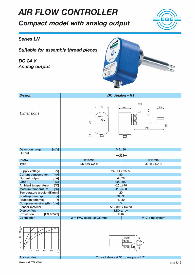
Design DC Analog • G1
Dimensions
Detection range [m/s] 0.5...30Output
ID-No. P11098 P11099
Type LN 450 GA-K LN 450 GA-S
Supply voltage [V] 24 DC ± 15 %Current consumption [mA] 80Current output [mA] 4...20Load RL [Ω] 200-500Ambient temperature [°C] -20...+70Medium temperature [°C] -20...+80Temperature gradient[K/min] 20Start-up time typ. [s] 20...90Reaction time typ. [s] 4...30Compressive strength [bar] 3Sensor material AISI 303 / DelrinDisplay flow LED-arrayProtection [EN 60529] IP 67Connection 2 m PVC-cable, 3x0.5 mm2 M12-plug system
Accessories Thread sleeve A 50..., see page 1.71
AIR FLOW CONTROLLER
Compact model with analog output
Series LN
Suitable for assembly thread pieces
DC 24 V
Analog output
RL
L+
L-
(1)BN
(4)BK
(3)BU
2
4
13
44
160
107
25
G1
ø6
ø1
8,8
50
78
12
WWW.VARITEL.COM E10205 1.45
4
8
12
16
20
0 20 40 60 80
mA
100%


FLOW CONTROLLER
Series 400 WWW.VARITEL.COM
Sensors
Gas Zone 0 and 1
Dust Zone 20 and 21
WWW.VARITEL.COM E10205 1.47

WWW.VARITEL.COM1.48 E10205
FLOW CONTROLLER
- Sensors Zone 0 - 1
Series STSEX
II 1/2 G EEx ia IIC T6
Category 1 / Category 2
G3/4 thread
NPT3/4 thread
Terminal clamps
Design G3/4 NPT3/4
Dimensions
Detection range [cm/s] Water 1...100 / Oil 3...200Sensor length [mm] 68 68ID-No. P11268 P11269
Type STSEX 01 STSEX 02Medium temperature [°C] -20...+60Zone 0, 1Ex marking II 1/2 G EEx ia IIC T6Certificate No. TÜV 98 ATEX 1298 XAmbient temperature [°C] Zone 0 T6: 45 Zone 1 T6: 45for temperature classes T5: 60 T5: 60
T4: 60 T4: 80Maximum values Pi = 0.69 W
Ci = negligibly smallLi = negligibly small
Housing material AISI 316 Ti • different materials on requestProtection [EN 60529] IP 67Connection terminal clamps
Notice For the connection to amplifiers SZA..., SEA..., see page 1.62 - 1.65
1
BN
2
WH
3
BU
4
BK
1 BN
2 WH
3 BU
4 BK
d26
d28
d30
d32
SEASensor
50
68
25
ø 7,4
ø 50
G 3/4
41
50
68
25
ø 7,4
ø 50
NPT 3/4
41
3 BU
1 BN
2 WH
4 BK
8
7
6
5
SZASensor

WWW.VARITEL.COM E10205 1.49
Design G1/4
Dimensions
Detection range [cm/s] Water 1...100 / Oil 3...200Sensor length [mm] 25 25 25 25 25
Fixed cable Plug Fixed cable Plug Fixed cableID-No. P11140 P11164 P11144 P11170 P11176
Type STS 101 K STS 101 S ST 101 K ST 101 S ST 101 KHMedium temperature [°C] -20...+60 -20...+85 +10...+120Zone 0 1 1Ex marking II 1/2 G EEx ia IIC T6 II 2 G EEx ib IIC T6 II 2 G EEx ib IIC T6Certificate No. TÜV 98 ATEX 1298 X TÜV 97 ATEX 1218 TÜV 97 ATEX 1218Ambient temperature [°C] T6: 45 T4: 60 T6: 50 T4: 85 T6: 50 T4: 100for temperature classes T5: 60 T3: 60 T5: 65 T3: 85 T5: 65 T3: 120Maximum values Pi = 0.69W
Ci = negligibly smallLi = negligibly small
Temperature gradient[K/min] 250Start-up time typ. [s] 8 ( 2...18 )Reaction time typ. [s] 2 ( 1...13 )Compressive strength [bar] 60Sensor material AISI 316 Ti • different materials on requestProtection [EN 60529] cable: IP 68 / plug: IP 67Connection 2 m PUR-cable 4x0.25 mm2 / 2 m FEP-cable
M12-plug system 4x0.25 mm2
Notice For the connection to amplifiers SZA..., SEA..., see page 1.62 - 1.65
FLOW CONTROLLER
- Sensors Zone 0 - 1 - 1/120 °C
251
3
ø7,3
12
19
4
3 1
2
1: BN
2: WH
3: BU
4: BK
1 BN
2 WH
3 BU
4 BK
d26
d28
d30
d32
SEASensor
3 BU
1 BN
2 WH
4 BK
8
7
6
5
SZASensor
Series STS und ST
II 1/2 G EEx ia IIC T6
II 2 G EEx ib IIC T6
Category 1 / Category 2
G1/4 thread
251
3
ø7,3
12
1912
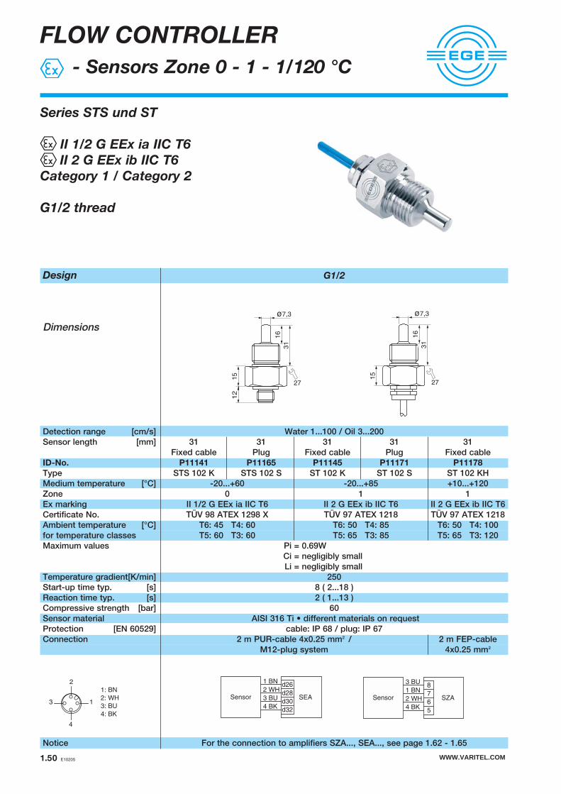
WWW.VARITEL.COM1.50 E10205
Design G1/2
Dimensions
Detection range [cm/s] Water 1...100 / Oil 3...200Sensor length [mm] 31 31 31 31 31
Fixed cable Plug Fixed cable Plug Fixed cableID-No. P11141 P11165 P11145 P11171 P11178
Type STS 102 K STS 102 S ST 102 K ST 102 S ST 102 KHMedium temperature [°C] -20...+60 -20...+85 +10...+120Zone 0 1 1Ex marking II 1/2 G EEx ia IIC T6 II 2 G EEx ib IIC T6 II 2 G EEx ib IIC T6Certificate No. TÜV 98 ATEX 1298 X TÜV 97 ATEX 1218 TÜV 97 ATEX 1218Ambient temperature [°C] T6: 45 T4: 60 T6: 50 T4: 85 T6: 50 T4: 100for temperature classes T5: 60 T3: 60 T5: 65 T3: 85 T5: 65 T3: 120Maximum values Pi = 0.69W
Ci = negligibly smallLi = negligibly small
Temperature gradient[K/min] 250Start-up time typ. [s] 8 ( 2...18 )Reaction time typ. [s] 2 ( 1...13 )Compressive strength [bar] 60Sensor material AISI 316 Ti • different materials on requestProtection [EN 60529] cable: IP 68 / plug: IP 67Connection 2 m PUR-cable 4x0.25 mm2 / 2 m FEP-cable
M12-plug system 4x0.25 mm2
Notice For the connection to amplifiers SZA..., SEA..., see page 1.62 - 1.65
FLOW CONTROLLER
- Sensors Zone 0 - 1 - 1/120 °C
4
3 1
2
1: BN
2: WH
3: BU
4: BK
1 BN
2 WH
3 BU
4 BK
d26
d28
d30
d32
SEASensor
3 BU
1 BN
2 WH
4 BK
8
7
6
5
SZASensor
Series STS und ST
II 1/2 G EEx ia IIC T6
II 2 G EEx ib IIC T6
Category 1 / Category 2
G1/2 thread
16
31
ø7,3
27
15
12
16
31
ø7,3
27
15

WWW.VARITEL.COM E10205 1.51
Design G1/2
Dimensions
Detection range [cm/s] Water 1...100 / Oil 3...200Sensor length [mm] 48 48 48 48 48
Fixed cable Plug Fixed cable Plug Fixed cableID-No. P11142 P11166 P11146 P11172 P11180
Type STS 103 K STS 103 S ST 103 K ST 103 S ST 103 KHMedium temperature [°C] -20...+60 -20...+85 +10...+120Zone 0 1 1Ex marking II 1/2 G EEx ia IIC T6 II 2 G EEx ib IIC T6 II 2 G EEx ib IIC T6Certificate No. TÜV 98 ATEX 1298 X TÜV 97 ATEX 1218 TÜV 97 ATEX 1218Ambient temperature [°C] T6: 45 T4: 60 T6: 50 T4: 85 T6: 50 T4: 100for temperature classes T5: 60 T3: 60 T5: 65 T3: 85 T5: 65 T3: 120Maximum values Pi = 0.69W
Ci = negligibly smallLi = negligibly small
Temperature gradient[K/min] 250Start-up time typ. [s] 8 ( 2...18 )Reaction time typ. [s] 2 ( 1...13 )Compressive strength [bar] 60Sensor material AISI 316 Ti • different materials on requestProtection [EN 60529] cable: IP 68 / plug: IP 67Connection 2 m PUR-cable 4x0.25 mm2 / 2 m FEP-cable
M12-plug system 4x0.25 mm2
Notice For the connection to amplifiers SZA..., SEA..., see page 1.62 - 1.65
FLOW CONTROLLER
- Sensors Zone 0 - 1 - 1/120 °C
4
3 1
2
1: BN
2: WH
3: BU
4: BK
1 BN
2 WH
3 BU
4 BK
d26
d28
d30
d32
SEASensor
3 BU
1 BN
2 WH
4 BK
8
7
6
5
SZASensor
Series STS und ST
II 1/2 G EEx ia IIC T6
II 2 G EEx ib IIC T6
Category 1 / Category 2
G1/2 thread
15
13
48
ø7,3
27
15
13
48
ø7,3
27
12

WWW.VARITEL.COM1.52 E10205
Design NPT1/2
Dimensions
Detection range [cm/s] Water 1...100 / Oil 3...200Sensor length [mm] 40 40 40 40 40
Fixed cable Plug Fixed cable Plug Fixed cableID-No. P11143 P11167 P11147 P11173 P11182
Type STS 104 K STS 104 S ST 104 K ST 104 S ST 104 KHMedium temperature [°C] -20...+60 -20...+85 +10...+120Zone 0 1 1Ex marking II 1/2 G EEx ia IIC T6 II 2 G EEx ib IIC T6 II 2 G EEx ib IIC T6Certificate No. TÜV 98 ATEX 1298 X TÜV 97 ATEX 1218 TÜV 97 ATEX 1218Ambient temperature [°C] T6: 45 T4: 60 T6: 50 T4: 85 T6: 50 T4: 100for temperature classes T5: 60 T3: 60 T5: 65 T3: 85 T5: 65 T3: 120Maximum values Pi = 0.69W
Ci = negligibly smallLi = negligibly small
Temperature gradient[K/min] 250Start-up time typ. [s] 8 ( 2...18 )Reaction time typ. [s] 2 ( 1...13 )Compressive strength [bar] 60Sensor material AISI 316 Ti • different materials on requestProtection [EN 60529] cable: IP 68 / plug: IP 67Connection 2 m PUR-cable 4x0.25 mm2 / 2 m FEP-cable
M12-plug system 4x0.25 mm2
Notice For the connection to amplifiers SZA..., SEA..., see page 1.62 - 1.65
FLOW CONTROLLER
- Sensors Zone 0 - 1 - 1/120 °C
4
3 1
2
1: BN
2: WH
3: BU
4: BK
1 BN
2 WH
3 BU
4 BK
d26
d28
d30
d32
SEASensor
3 BU
1 BN
2 WH
4 BK
8
7
6
5
SZASensor
Series STS und ST
II 1/2 G EEx ia IIC T6
II 2 G EEx ib IIC T6
Category 1 / Category 2
NPT1/2 thread
ø17
ø7,3
13
40
27
15
12
ø17
ø7,3
13
40
27
15

WWW.VARITEL.COM E10205 1.53
Design G3/4
Dimensions
Detection range [cm/s] Water 1...100 / Oil 3...200Sensor length [mm] 48 48 48 48 48
Fixed cable Plug Fixed cable Plug Fixed cableID-No. P11168 P11169 P11174 P11175 P11184
Type STS 106 K STS 106 S ST 106 K ST 106 S ST 106 KHMedium temperature [°C] -20...+60 -20...+85 +10...+120Zone 0 1 1Ex marking II 1/2 G EEx ia IIC T6 II 2 G EEx ib IIC T6 II 2 G EEx ib IIC T6Certificate No. TÜV 98 ATEX 1298 X TÜV 97 ATEX 1218 TÜV 97 ATEX 1218Ambient temperature [°C] T6: 45 T4: 60 T6: 50 T4: 85 T6: 50 T4: 100for temperature classes T5: 60 T3: 60 T5: 65 T3: 85 T5: 65 T3: 120Maximum values Pi = 0.69W
Ci = negligibly smallLi = negligibly small
Temperature gradient[K/min] 250Start-up time typ. [s] 8 ( 2...18 )Reaction time typ. [s] 2 ( 1...13 )Compressive strength [bar] 60Sensor material AISI 316 Ti • different materials on requestProtection [EN 60529] cable: IP 68 / plug: IP 67Connection 2 m PUR-cable 4x0.25 mm2 / 2 m FEP-cable
M12-plug system 4x0.25 mm2
Notice For the connection to amplifiers SZA..., SEA..., see page 1.62 - 1.65
FLOW CONTROLLER
- Sensors Zone 0 - 1 - 1/120 °C
4
3 1
2
1: BN
2: WH
3: BU
4: BK
1 BN
2 WH
3 BU
4 BK
d26
d28
d30
d32
SEASensor
3 BU
1 BN
2 WH
4 BK
8
7
6
5
SZASensor
Series STS und ST
II 1/2 G EEx ia IIC T6
II 2 G EEx ib IIC T6
Category 1 / Category 2
G3/4 thread
13
48
ø7,3
32
15
12
13
48
ø7,3
321
5

WWW.VARITEL.COM1.54 E10205
Design G1/2
Dimensions
Detection range [cm/s] Water 1...100 / Oil 3...200Sensor length [mm] 48 48 48 48 48
Fixed cable Plug Fixed cable Plug Fixed cableID-No. P11186 P11187 P11192 P11193 P11198
Type STS 110 K STS 110 S ST 110 K ST 110 S ST 110 KHMedium temperature [°C] -20...+60 -20...+85 +10...+120Zone 0 1 1Ex marking II 1/2 G EEx ia IIC T6 II 2 G EEx ib IIC T6 II 2 G EEx ib IIC T6Certificate No. TÜV 98 ATEX 1298 X TÜV 97 ATEX 1218 TÜV 97 ATEX 1218Ambient temperature [°C] T6: 45 T4: 60 T6: 50 T4: 85 T6: 50 T4: 100for temperature classes T5: 60 T3: 60 T5: 65 T3: 85 T5: 65 T3: 120Maximum values Pi = 0.69W
Ci = negligibly smallLi = negligibly small
Temperature gradient[K/min] 250Start-up time typ. [s] 8 ( 2...18 )Reaction time typ. [s] 2 ( 1...13 )Compressive strength [bar] 60Sensor material AISI 316 Ti • different materials on requestProtection [EN 60529] cable: IP 68 / plug: IP 67Connection 2 m PUR-cable 4x0.25 mm2 / 2 m FEP-cable
M12-plug system 4x0.25 mm2
Notice For the connection to amplifiers SZA..., SEA..., see page 1.62 - 1.65
13
48
20
15
Ø17
Ø 7,3
27
13
48
20
15
Ø17
Ø 7,3
27
M 12
FLOW CONTROLLER
- Sensors Zone 0 - 1 - 1/120 °C
1 BN
2 WH
3 BU
4 BK
d26
d28
d30
d32
SEASensor
3 BU
1 BN
2 WH
4 BK
8
7
6
5
SZASensor
Series STS und ST
II 1/2 G EEx ia IIC T6
II 2 G EEx ib IIC T6
Category 1 / Category 2
G1/2 short thread
4
3 1
2
1: BN
2: WH
3: BU
4: BK

WWW.VARITEL.COM E10205 1.55
Design G1/2 Welded flange
Dimensions
Detection range [cm/s] Water 1...100 / Oil 3...200Sensor length [mm] 80 80 80 80 80 80Process connection Thread Normflansch Thread Normflansch Thread NormflanschID-No. P11188 P11191 P11194 P11197 P11200 P11203
Type STS 110 K- STS 111 K- ST 110 K- ST 111 K- ST 110 KH- ST 111 KH-L80 L80 L80 L80 L80 L80
Medium temperature [°C] -20...+60 -20...+85 +10...+120Zone 0 1 1Ex marking II 1/2 G EEx ia IIC T6 II 2 G EEx ib IIC T6 II 2 G EEx ib IIC T6Certificate No. TÜV 98 ATEX 1298 X TÜV 97 ATEX 1218 TÜV 97 ATEX 1218Ambient temperature [°C] T6: 45 T4: 60 T6: 50 T4: 85 T6: 50 T4: 100for temperature classes T5: 60 T3: 60 T5: 65 T3: 85 T5: 65 T3: 120Maximum values Pi = 0.69W
Ci = negligibly smallLi = negligibly small
Temperature gradient[K/min] 250Start-up time typ. [s] 8 ( 2...18 )Reaction time typ. [s] 2 ( 1...13 )Compressive strength [bar] 60Sensor material AISI 316 Ti • different materials on requestProtection [EN 60529] cable: IP 68 / plug: IP 67Connection 2 m PUR-cable 2 m FEP-cable
4x0.25 mm2 4x0.25 mm2
Notice For the connection to amplifiers SZA..., SEA..., see page 1.62 - 1.65
13
80
20
15
Ø17
Ø 7,3
27
FLOW CONTROLLER
- Sensors Zone 0 - 1 - 1/120 °C
1 BN
2 WH
3 BU
4 BK
d26
d28
d30
d32
SEASensor
3 BU
1 BN
2 WH
4 BK
8
7
6
5
SZASensor
Series STS und ST
II 1/2 G EEx ia IIC T6
II 2 G EEx ib IIC T6
Category 1 / Category 2
G1/2 short thread
Welded flange
Length 80 mm
18
Ø17
DN25 / PN40
80
13
Ø7,3

WWW.VARITEL.COM1.56 E10205
Design G1/2 Welded flange
Dimensions
Detection range [cm/s] Water 1...100 / Oil 3...200Sensor length [mm] 110 110 110 110 110 110Process connection Thread Flange Thread Flange Thread FlangeID-No. P11189 P11148 P11195 P11150 P11201 P11204
Type STS 110 K- STS 111 K- ST 110 K- ST 111 K- ST 110 KH- ST 111 KH-L110 L110 L110 L110 L110 L110
Medium temperature [°C] -20...+60 -20...+85 +10...+120Zone 0 1 1Ex marking II 1/2 G EEx ia IIC T6 II 2 G EEx ib IIC T6 II 2 G EEx ib IIC T6Certificate No. TÜV 98 ATEX 1298 X TÜV 97 ATEX 1218 TÜV 97 ATEX 1218Ambient temperature [°C] T6: 45 T4: 60 T6: 50 T4: 85 T6: 50 T4: 100for temperature classes T5: 60 T3: 60 T5: 65 T3: 85 T5: 65 T3: 120Maximum values Pi = 0.69W
Ci = negligibly smallLi = negligibly small
Temperature gradient[K/min] 250Start-up time typ. [s] 8 ( 2...18 )Reaction time typ. [s] 2 ( 1...13 )Compressive strength [bar] 60Sensor material AISI 316 Ti • different materials on requestProtection [EN 60529] cable: IP 68 / plug: IP 67Connection 2 m PUR-cable 2 m FEP-cable
4x0.25 mm2 4x0.25 mm2
Notice For the connection to amplifiers SZA..., SEA..., see page 1.62 - 1.65
13
110
20
15
Ø17
Ø 7,3
27
FLOW CONTROLLER
- Sensors Zone 0 - 1 - 1/120 °C
1 BN
2 WH
3 BU
4 BK
d26
d28
d30
d32
SEASensor
3 BU
1 BN
2 WH
4 BK
8
7
6
5
SZASensor
Series STS und ST
II 1/2 G EEx ia IIC T6
II 2 G EEx ib IIC T6
Category 1 / Category 2
G1/2 short thread
Welded flange
Length 110 mm
18
Ø17
DN25 / PN40
Ø7,3
110
13

WWW.VARITEL.COM E10205 1.57
Design G1/2 Welded flange
Dimensions
Detection range [cm/s] Water 1...100 / Oil 3...200Sensor length [mm] 140 140 140 140 140 140Process connection Thread Flange Thread Flange Thread FlangeID-No. P11190 P11149 P11196 P11151 P11202 P11205
Type STS 110 K- STS 111 K- ST 110 K- ST 111 K- ST 110 KH- ST 111 KH-L140 L140 L140 L140 L140 L140
Medium temperature [°C] -20...+60 -20...+85 +10...+120Zone 0 1 1Ex marking II 1/2 G EEx ia IIC T6 II 2 G EEx ib IIC T6 II 2 G EEx ib IIC T6Certificate No. TÜV 98 ATEX 1298 X TÜV 97 ATEX 1218 TÜV 97 ATEX 1218Ambient temperature [°C] T6: 45 T4: 60 T6: 50 T4: 85 T6: 50 T4: 100for temperature classes T5: 60 T3: 60 T5: 65 T3: 85 T5: 65 T3: 120Maximum values Pi = 0.69W
Ci = negligibly smallLi = negligibly small
Temperature gradient[K/min] 250Start-up time typ. [s] 8 ( 2...18 )Reaction time typ. [s] 2 ( 1...13 )Compressive strength [bar] 60Sensor material AISI 316 Ti • different materials on requestProtection [EN 60529] cable: IP 68 / plug: IP 67Connection 2 m PUR-cable 2 m FEP-cable
4x0.25 mm2 4x0.25 mm2
Notice For the connection to amplifiers SZA..., SEA..., see page 1.62 - 1.65
13
140
20
15
Ø17
Ø 7,3
27
FLOW CONTROLLER
- Sensors Zone 0 - 1 - 1/120 °C
1 BN
2 WH
3 BU
4 BK
d26
d28
d30
d32
SEASensor
3 BU
1 BN
2 WH
4 BK
8
7
6
5
SZASensor
Series STS und ST
II 1/2 G EEx ia IIC T6
II 2 G EEx ib IIC T6
Category 1 / Category 2
G1/2 short thread
Welded flange
Length 140 mm
18
Ø17
DN25 / PN40
Ø7,3
140
13

WWW.VARITEL.COM1.58 E10205
AIR FLOW CONTROLLER
- Sensors Zone 0 - 20
Design G1/2
Dimensions
Detection range [m/s] 2...25 Output Fixed cable PlugID-No. P11152 P11206
Type STS 212 K STS 212 SMedium temperature [°C] -20...+60Zone 0/20Ex marking II 1 D T137 °C IP67 / II 1G EEx ia IIC T6Certificate No. TÜV 02 ATEX 1816 XAmbient temperature [°C] T4: 45for temperature classes T3: 60Maximum values Pi = 0.69W
Ci = negligibly smallLi = negligibly small
Temperature gradient[K/min] 1Start-up time typ. [s] 10...40Reaction time typ. [s] 5 (2...30)Compressive strength [bar] 10Sensor material AISI 316 Ti • different materials on requestProtection [EN 60529] IP 67Connection 2 m PUR-cable 4x0.25 mm2 / M12-plug system
Notice For the connection to amplifiers SZA...., SEA..., see page 1.62 - 1.65
Series STS
Dust II 1 D T137 °C
Gas II 1 G EEx ia IIC T6
G1/2 thread
1 BN
2 WH
3 BU
4 BK
d26
d28
d30
d32
SEASensor
3 BU
1 BN
2 WH
4 BK
8
7
6
5
SZASensor
65
15
15
25
27
ø6,7
G1/2
ø15 65
15
15
25
27
ø6,7
G1/2
ø15
12

AIR FLOW CONTROLLER
- Sensors Zone 0 - 1
Series STS
Dust II 1 D T100 °C
Gas II 1/2 G EEx ia IIC T4
Gas II 1 G EEx ia IIC T6
G1/2 thread
High temperature 120 °C
WWW.VARITEL.COM E10205 1.59
1 BN
2 WH
3 BU
4 BK
d26
d28
d30
d32
SEASensor
3 BU
1 BN
2 WH
4 BK
8
7
6
5
SZASensor
48
15
29
G1/2
ø6
9,5
2748
15
29
G1/2
ø6
9,5
2712
Design G1/2
Dimensions
Detection range [m/s] 2...25 Output Fixed cable Plug Fixed cableID-No. P11153 P11207 P11212
Type STS 215 K STS 215 S STS 215 KHMedium temperature [°C] -20...+60 +10...+60 +10...+120Zone 0/20 0 1/2Ex marking II 1 D T100 °C IP67 / II 1 G EEx ia IIC T6 II 1/2 G EEx ia IIC T4Certificate No. TÜV 02 ATEX 1816 X TÜV 02 ATEX 1816 XAmbient temperature [°C] T6: 35 T4: 60 T6: 35 T4: 60 T6: 45 T4: 95for temperature classes T5: 45 T3: 60 T5: 45 T3: 60 T5: 65 T3: 120Maximum values Pi = 0,69W
Ci = negligibly smallLi = negligibly small
Temperature gradient[K/min] 10Start-up time typ. [s] 5...20Reaction time typ. [s] 3 (2...30)Compressive strength [bar] 10Sensor material AISI 316 Ti • different materials on requestProtection [EN 60529] IP 67 IP 68Connection 2 m FEP-cable M12-plug system 2 m PUR-cable
4x0.25 mm2 4x0.25 mm2
Notice For the connection to amplifiers SZA..., SEA..., see page 1.62 - 1.65
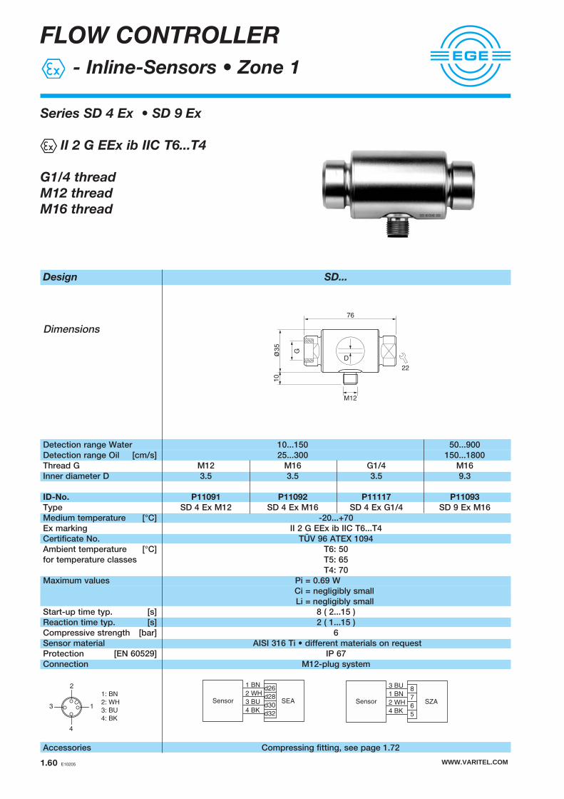
WWW.VARITEL.COM1.60 E10205
FLOW CONTROLLER
- Inline-Sensors • Zone 1
Design SD...
Dimensions
Detection range Water 10...150 50...900Detection range Oil [cm/s] 25...300 150...1800Thread G M12 M16 G1/4 M16Inner diameter D 3.5 3.5 3.5 9.3
ID-No. P11091 P11092 P11117 P11093
Type SD 4 Ex M12 SD 4 Ex M16 SD 4 Ex G1/4 SD 9 Ex M16Medium temperature [°C] -20...+70Ex marking II 2 G EEx ib IIC T6...T4Certificate No. TÜV 96 ATEX 1094Ambient temperature [°C] T6: 50for temperature classes T5: 65
T4: 70Maximum values Pi = 0.69 W
Ci = negligibly smallLi = negligibly small
Start-up time typ. [s] 8 ( 2...15 )Reaction time typ. [s] 2 ( 1...15 )Compressive strength [bar] 6Sensor material AISI 316 Ti • different materials on requestProtection [EN 60529] IP 67Connection M12-plug system
Accessories Compressing fitting, see page 1.72
Series SD 4 Ex • SD 9 Ex
II 2 G EEx ib IIC T6...T4
G1/4 thread
M12 thread
M16 thread
D
76
G
10
ø35
22
M12
1 BN
2 WH
3 BU
4 BK
d26
d28
d30
d32
SEASensor
3 BU
1 BN
2 WH
4 BK
8
7
6
5
SZASensor
4
3 1
2
1: BN
2: WH
3: BU
4: BK

WWW.VARITEL.COM E10205 1.61
FLOW CONTROLLER
- Lightning protection
II 2 (1) G EEx ia IIC T4 Zone 0
The lightning protection SBGX 01 is placed
between the sensor and the amplifier
Lightning overvoltage is discharged to earth.
Design SBGX 01
Dimensions
ID-No. Z01007
Type SBGX 01
Ex marking II 2 (1) G EEx ia IIC T4Certificate No. TÜV 03 ATEX 2073Ambient temperature [°C] -20...+120for temperature classes T4 : 120Maximum values Ui = 45 V
Ii = 3.3 APi = 1.3 WCi = negligibly smallLi = negligibly small
Housing material aIuminiumProtection [EN 60529] IP 67Connection clamp space
2
1
3
4
5
6
7
8
BK
BU
WH
BN
BN
WH
BU
BK
SBGX 01Verstärker
AmplifierSensor
125
801
54
2
PG 9
PG 13,5

WWW.VARITEL.COM1.62 E10205
Design SZA 400 Ex...
Dimensions
ID-No. P10706 P10707 P10708
Type SZA 400 Ex-230 SZA 400 Ex-115 SZA 400 Ex-24
Supply voltage [V] 230 AC ± 10% 115 AC ± 10% 24 DC ± 15%Ex marking II (1) GD [EEx ia] IICCertificate No. TÜV 96 ATEX 1097Maximum values Uo = 12.6 V
Io = 200 mARi = 68.5 Ω
external capacitance 170 nFexternal inductance 0.5 mHTime delay off adjustable [s] 0...25Output relay / change-overSwitching voltage [V] 250 AC / 60 DCSwitching current [A] 4 AC / 0.5 DCSwitching power cos ϕ >0.7 / L/R <200 msAmbient temperature [°C] -20...+60Protection [EN 60529] terminal: IP 20 / housing: IP 40Connection terminal screws
FLOW CONTROLLER
- Amplifiers
Series SZA
II (1) GD [EEx ia] IIC
AC 230 V • AC 115 V
DC 24 V
Relay output
Time delay
Cable break and short circuit monitoring
110
7555
3 BU
1 BN
2 WH
4 BK
L-
L+
SZA 400
Sensor
Rel.
Strömung
flow
16
15
14
13
12
11
10
9
8
7
6
5
4
3
2
1

WWW.VARITEL.COM E10205 1.63
FLOW CONTROLLER
- Amplifier
Series SZA
II (1) GD [EEx ia] IIC
DC 24 V
Analog output
LED-Display
Cable break and short circuit monitoring
Design SZA 400 GA-Ex
Dimensions
ID-No. P11257
Type SZA 400 GA-Ex
Supply voltage [V] 24 DC ± 15 %Ex marking II (1) GD [EEx ia] IICCertificate No. TÜV 02 ATEX 1821Maximum values Uo = 13.65 V
Io = 200 mAPo = 690 mW
external capacitance 170 nFexternal inductance 0.5 mHOutput analogCurrent output [mA] 4...20 DCLoad RL [Ω] 50...500Ambient temperature [°C] -20...+60Protection [EN 60529] terminal: IP 20 / housing: IP 40Connection terminal screws
3 BU
1 BN
2 WH
4 BK
L-
L+
SZA 400 GA-Ex
Sensor
Strömung
flow
analog
16
15
13
12
8
7
6
5
4
3
2
1RL
110
7555

Design SEA 400 Ex-24 SEA 401 Ex-24 SEA 405 GA-Ex
Dimensions
ID-No. P10705 P10709 P11253
Type SEA 400 Ex-24 SEA 401 Ex-24 SEA 405 GA-Ex
Supply voltage [V] 24 DC ± 15% 24 DC ± 15%Ex marking II (1) GD [EEx ia] IIC II (1) GD [EEx ia] IICCertificate No. TÜV 97 ATEX 1182X TÜV 01 ATEX 1678XMaximum values Uo = 13.65 V Uo = 13.65 V
Io = 200 mA Io = 200 mARi = 68.5 Ω Ri = 68.5 Ω
Po = 0.69 W Po = 0.69 Wexternal capacitance 150 nF 150 nFexternal inductance 0.87 mH 0.87 mHOutput 1 (relay/change over) flow analog 4...20mAOutput 2 (relay/change over) temperature failure -Load RL [Ω] - 200...500Switching voltage [V] 30 AC / 36 DC -Switching current [A] 2 -Switching power max. 60 VA / 50 W -Ambient temperature [°C] -20...+60 -20...+60Protection [EN 60529] IP 20 IP 20
FLOW CONTROLLER
- Amplifiers
Series SEA
II (1) GD [EEx ia] IIC
DC 24 V
Relay output
Analog output
LED-Display
Time delay on/off programmable
175
128
Steckverbinder nach DIN EN 41612
Plug connection to DIN EN 41612
F 32, z+d
4TE = 20,32 mm
1 BN
2 WH
3 BU
4 BK
L+
L-
Sensor
zd2
zd4
z6
z8
d8
z10
z12
d12
d26
d28
d30
d32
Rel. II
Rel. I
1 BN
2 WH
3 BU
4 BK
L+
L-
Sensor
zd2
zd4
z14
d26
d28
d30
d32
RL
Strömung
flow
analog
WWW.VARITEL.COM1.64 E10205
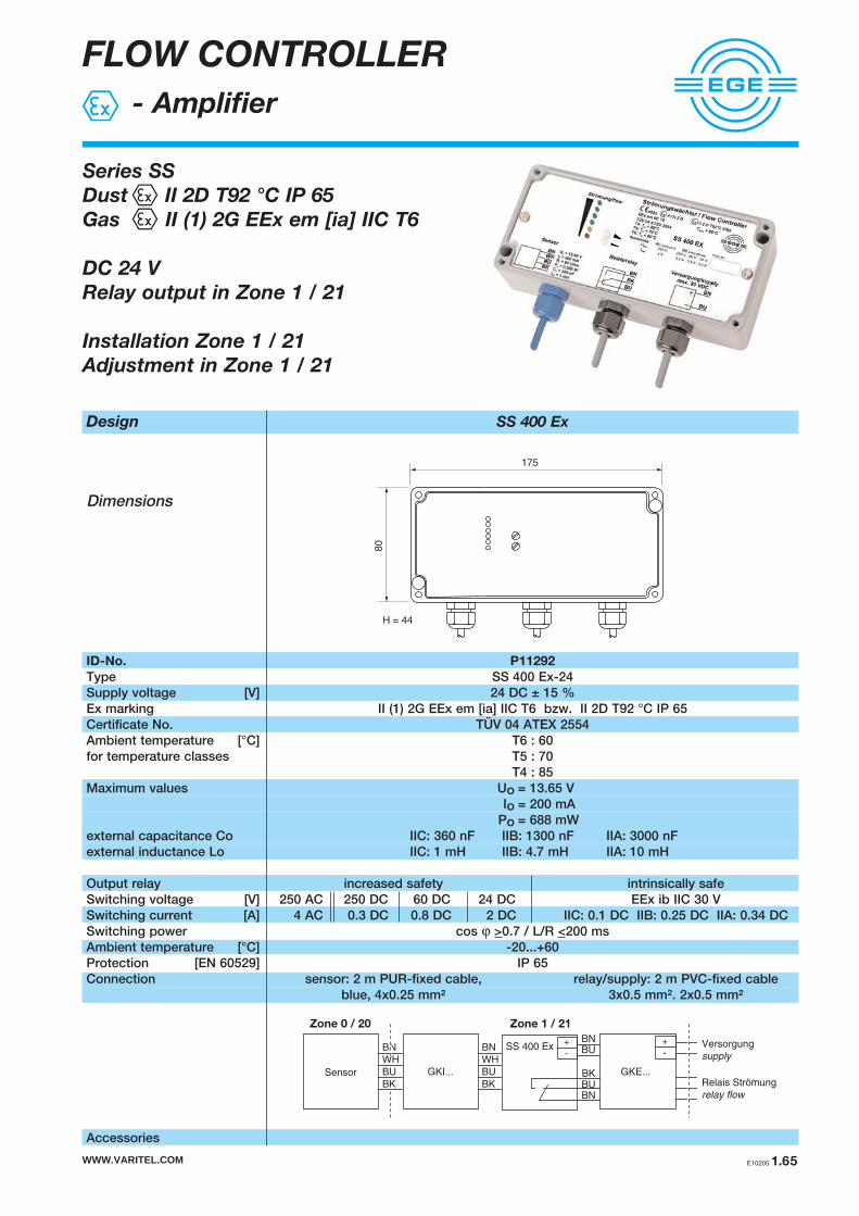
FLOW CONTROLLER
- Amplifier
Series SS
Dust II 2D T92 °C IP 65
Gas II (1) 2G EEx em [ia] IIC T6
DC 24 V
Relay output in Zone 1 / 21
Installation Zone 1 / 21
Adjustment in Zone 1 / 21
Design SS 400 Ex
Dimensions
ID-No. P11292
Type SS 400 Ex-24Supply voltage [V] 24 DC ± 15 %Ex marking II (1) 2G EEx em [ia] IIC T6 bzw. II 2D T92 °C IP 65Certificate No. TÜV 04 ATEX 2554Ambient temperature [°C] T6 : 60for temperature classes T5 : 70
T4 : 85Maximum values Uo = 13.65 V
Io = 200 mAPo = 688 mW
external capacitance Co IIC: 360 nF IIB: 1300 nF IIA: 3000 nFexternal inductance Lo IIC: 1 mH IIB: 4.7 mH IIA: 10 mH
Output relay increased safety intrinsically safeSwitching voltage [V] 250 AC 250 DC 60 DC 24 DC EEx ib IIC 30 VSwitching current [A] 4 AC 0.3 DC 0.8 DC 2 DC IIC: 0.1 DC IIB: 0.25 DC IIA: 0.34 DCSwitching power cos ϕ >0.7 / L/R <200 ms Ambient temperature [°C] -20...+60Protection [EN 60529] IP 65Connection sensor: 2 m PUR-fixed cable, relay/supply: 2 m PVC-fixed cable
blue, 4x0.25 mm² 3x0.5 mm². 2x0.5 mm²
Accessories
175
80
H = 44
WWW.VARITEL.COM E10205 1.65
SS 400 Ex
BKBUBN
+-
BNBUBN
WH
BU
BK
GKI...SensorRelais Strömung
relay flow
Versorgung
supply
+-
GKE...
Zone 0 / 20 Zone 1 / 21
BN
WH
BU
BK

FLOW CONTROLLER
- Housing for screw terminals
Series GK...
II 2 G EEx e II T6
II 2 G EEx ia IIC T6
II 2 G EEx e [ia] IIC T6
II 2 D IP 65 T75 °C
For the connection of supply-
and signal lines in Zone 1 / 21
Design GK...
Dimensions
ID-No. Z01168 Z01169 Z01170 Z01171 Z01172
Type GKE 60 GKE 100 GKI 60 GKI 100 GKEI 100Amount of terminals 4 8 4 8 4 EEx e + 4 EEx iaDimensions [mm] 58x64 98x64 58x64 98x64 98x64Electric circuit increased safety intrinsically safe intrinsically safe + increased safety
Ex marking II 2 G EEx e II T6 II 2 G EEx ia IIC T6 II 2 G EEx e [ia] IIC T6II 2 D IP 65 T75 °C II 2 D IP 65 T75 °C II 2 D IP 65 T75 °C
Certificate No. BVS 05 ATEX E022 XAmbient temperature [°C] -20...+70for temperature classes [°C] T4, T5, T6 : 70Rated voltage [V] 275Rated current [A] 2Cross section wires single wire 0.5...2.5 mm²
multistrand 0.5...1.5 mm²Cable diameter [mm] 4...8Housing material aluminiumProtection [EN 60529] IP 65Connction terminal space
64
H = 36
58
19
WWW.VARITEL.COM1.66 E10205
Zone 0 / 20 Zone 1 / 21 Zone 1 / 21Zone 1 / 21
amplifier GKE...sensor GKI...
sensor circuit
intrinsically safe
supply circuit
increased safetyamplifier GKEI...
output
increased safety
The enclosure for screw terminals type GK... is designed for the connection of intrinsically safe and / or non-intrinsi-cally safe circuits in explosion-hazardous areas of category 2 (zone 1 and 21).
64
H = 36
98
19

ACCESSORIES
Flow controller
WWW.VARITEL.COM E10205 1.67
Accessories
and
Certificates
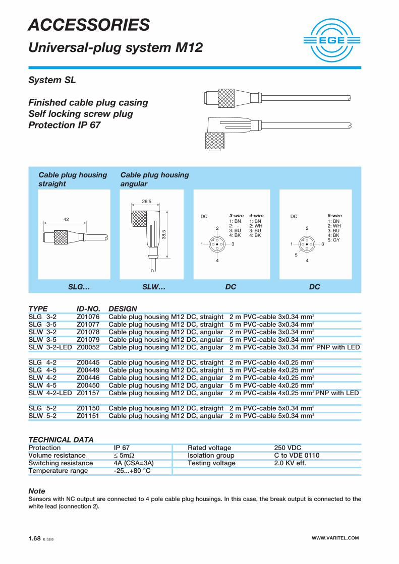
WWW.VARITEL.COM1.68 E10205
TYPE ID-NO. DESIGNSLG 3-2 Z01076 Cable plug housing M12 DC, straight 2 m PVC-cable 3x0.34 mm2
SLG 3-5 Z01077 Cable plug housing M12 DC, straight 5 m PVC-cable 3x0.34 mm2
SLW 3-2 Z01078 Cable plug housing M12 DC, angular 2 m PVC-cable 3x0.34 mm2
SLW 3-5 Z01079 Cable plug housing M12 DC, angular 5 m PVC-cable 3x0.34 mm2
SLW 3-2-LED Z00052 Cable plug housing M12 DC, angular 2 m PVC-cable 3x0.34 mm2 PNP with LED
SLG 4-2 Z00445 Cable plug housing M12 DC, straight 2 m PVC-cable 4x0.25 mm2
SLG 4-5 Z00449 Cable plug housing M12 DC, straight 5 m PVC-cable 4x0.25 mm2
SLW 4-2 Z00446 Cable plug housing M12 DC, angular 2 m PVC-cable 4x0.25 mm2
SLW 4-5 Z00450 Cable plug housing M12 DC, angular 5 m PVC-cable 4x0.25 mm2
SLW 4-2-LED Z01157 Cable plug housing M12 DC, angular 2 m PVC-cable 4x0.25 mm2 PNP with LED
SLG 5-2 Z01150 Cable plug housing M12 DC, straight 2 m PVC-cable 5x0.34 mm2
SLW 5-2 Z01151 Cable plug housing M12 DC, angular 2 m PVC-cable 5x0.34 mm2
TECHNICAL DATAProtection IP 67 Rated voltage 250 VDCVolume resistance ≤ 5mΩ Isolation group C to VDE 0110Switching resistance 4A (CSA=3A) Testing voltage 2.0 KV eff.Temperature range -25...+80 °C
NoteSensors with NC output are connected to 4 pole cable plug housings. In this case, the break output is connected to thewhite lead (connection 2).
42
SLG…
26,5
38,5
SLW… DC
System SL
Finished cable plug casing
Self locking screw plug
Protection IP 67
ACCESSORIES
Universal-plug system M12
DC
1
2
3
4
5
5-wire
1: BN2: WH3: BU4: BK5: GY
DC
DC 3-wire 4-wire
1
2
3
4
1: BN2: - 3: BU4: BK
1: BN2: WH3: BU4: BK
Cable plug housing
straight
Cable plug housing
angular
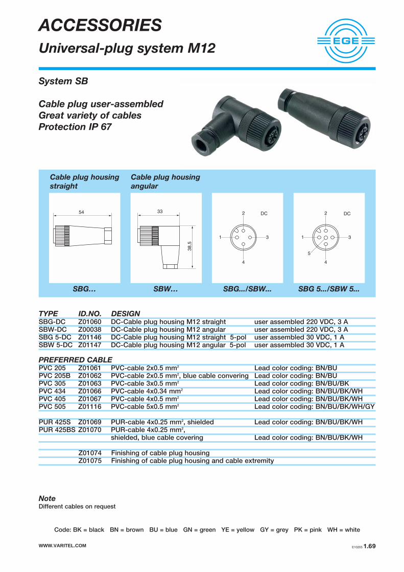
WWW.VARITEL.COM E10205 1.69
ACCESSORIES
Universal-plug system M12
Code: BK = black BN = brown BU = blue GN = green YE = yellow GY = grey PK = pink WH = white
TYPE ID.NO. DESIGNSBG-DC Z01060 DC-Cable plug housing M12 straight user assembled 220 VDC, 3 ASBW-DC Z00038 DC-Cable plug housing M12 angular user assembled 220 VDC, 3 ASBG 5-DC Z01146 DC-Cable plug housing M12 straight 5-pol user assembled 30 VDC, 1 ASBW 5-DC Z01147 DC-Cable plug housing M12 angular 5-pol user assembled 30 VDC, 1 A
PREFERRED CABLEPVC 205 Z01061 PVC-cable 2x0.5 mm2 Lead color coding: BN/BUPVC 205B Z01062 PVC-cable 2x0.5 mm2, blue cable convering Lead color coding: BN/BU PVC 305 Z01063 PVC-cable 3x0.5 mm2 Lead color coding: BN/BU/BKPVC 434 Z01066 PVC-cable 4x0.34 mm2 Lead color coding: BN/BU/BK/WHPVC 405 Z01067 PVC-cable 4x0.5 mm2 Lead color coding: BN/BU/BK/WHPVC 505 Z01116 PVC-cable 5x0.5 mm2 Lead color coding: BN/BU/BK/WH/GY
PUR 425S Z01069 PUR-cable 4x0.25 mm2, shielded Lead color coding: BN/BU/BK/WHPUR 425BS Z01070 PUR-cable 4x0.25 mm2,
shielded, blue cable covering Lead color coding: BN/BU/BK/WH
Z01074 Finishing of cable plug housingZ01075 Finishing of cable plug housing and cable extremity
NoteDifferent cables on request
54
Cable plug housing
straight
SBG…
38,5
33
Cable plug housing
angular
SBW…
4
1 3
2
5
DC
SBG 5.../SBW 5...
4
1 3
2 DC
SBG.../SBW...
System SB
Cable plug user-assembled
Great variety of cables
Protection IP 67
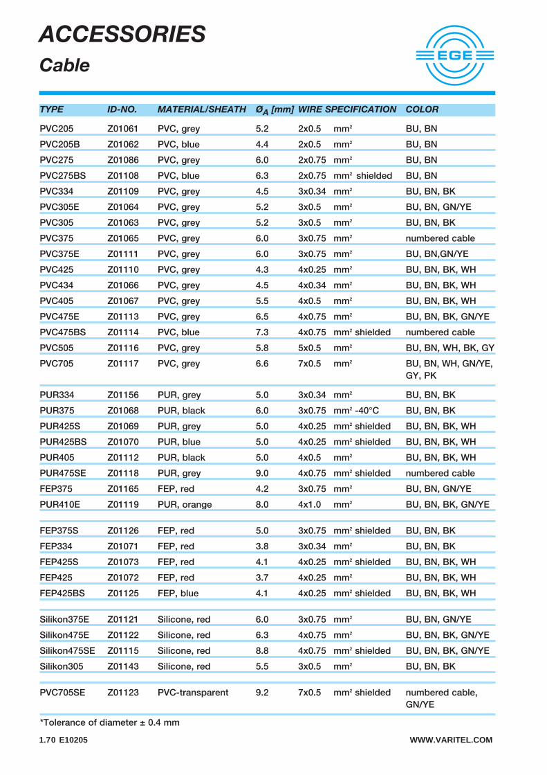
1.70 E10205 WWW.VARITEL.COM
ACCESSORIES
Cable
TYPE ID-NO. MATERIAL/SHEATH ØA [mm] WIRE SPECIFICATION COLOR
PVC205 Z01061 PVC, grey 5.2 2x0.5 mm2 BU, BN
PVC205B Z01062 PVC, blue 4.4 2x0.5 mm2 BU, BN
PVC275 Z01086 PVC, grey 6.0 2x0.75 mm2 BU, BN
PVC275BS Z01108 PVC, blue 6.3 2x0.75 mm2 shielded BU, BN
PVC334 Z01109 PVC, grey 4.5 3x0.34 mm2 BU, BN, BK
PVC305E Z01064 PVC, grey 5.2 3x0.5 mm2 BU, BN, GN/YE
PVC305 Z01063 PVC, grey 5.2 3x0.5 mm2 BU, BN, BK
PVC375 Z01065 PVC, grey 6.0 3x0.75 mm2 numbered cable
PVC375E Z01111 PVC, grey 6.0 3x0.75 mm2 BU, BN,GN/YE
PVC425 Z01110 PVC, grey 4.3 4x0.25 mm2 BU, BN, BK, WH
PVC434 Z01066 PVC, grey 4.5 4x0.34 mm2 BU, BN, BK, WH
PVC405 Z01067 PVC, grey 5.5 4x0.5 mm2 BU, BN, BK, WH
PVC475E Z01113 PVC, grey 6.5 4x0.75 mm2 BU, BN, BK, GN/YE
PVC475BS Z01114 PVC, blue 7.3 4x0.75 mm2 shielded numbered cable
PVC505 Z01116 PVC, grey 5.8 5x0.5 mm2 BU, BN, WH, BK, GY
PVC705 Z01117 PVC, grey 6.6 7x0.5 mm2 BU, BN, WH, GN/YE,GY, PK
PUR334 Z01156 PUR, grey 5.0 3x0.34 mm2 BU, BN, BK
PUR375 Z01068 PUR, black 6.0 3x0.75 mm2 -40°C BU, BN, BK
PUR425S Z01069 PUR, grey 5.0 4x0.25 mm2 shielded BU, BN, BK, WH
PUR425BS Z01070 PUR, blue 5.0 4x0.25 mm2 shielded BU, BN, BK, WH
PUR405 Z01112 PUR, black 5.0 4x0.5 mm2 BU, BN, BK, WH
PUR475SE Z01118 PUR, grey 9.0 4x0.75 mm2 shielded numbered cable
FEP375 Z01165 FEP, red 4.2 3x0.75 mm2 BU, BN, GN/YE
PUR410E Z01119 PUR, orange 8.0 4x1.0 mm2 BU, BN, BK, GN/YE
FEP375S Z01126 FEP, red 5.0 3x0.75 mm2 shielded BU, BN, BK
FEP334 Z01071 FEP, red 3.8 3x0.34 mm2 BU, BN, BK
FEP425S Z01073 FEP, red 4.1 4x0.25 mm2 shielded BU, BN, BK, WH
FEP425 Z01072 FEP, red 3.7 4x0.25 mm2 BU, BN, BK, WH
FEP425BS Z01125 FEP, blue 4.1 4x0.25 mm2 shielded BU, BN, BK, WH
Silikon375E Z01121 Silicone, red 6.0 3x0.75 mm2 BU, BN, GN/YE
Silikon475E Z01122 Silicone, red 6.3 4x0.75 mm2 BU, BN, BK, GN/YE
Silikon475SE Z01115 Silicone, red 8.8 4x0.75 mm2 shielded BU, BN, BK, GN/YE
Silikon305 Z01143 Silicone, red 5.5 3x0.5 mm2 BU, BN, BK
PVC705SE Z01123 PVC-transparent 9.2 7x0.5 mm2 shielded numbered cable, GN/YE
*Tolerance of diameter ± 0.4 mm

WWW.VARITEL.COM E10205 1.71
ACCESSORIES
Flow controller
TYPE ID.NO. DIMENSIONS DESIGN
Flange – Ø 20 Z01106 Plastic - flange with drilled hole Ø 20 mm
for sensors type LN 520 / LN 020
Flange DN25/PN40 Z01001 Flange 1.4571 (AISI 316)EN 1092-1/05 A (DIN 2527)with central thread G1/2
for sensors type ST… with G1/2
A501 Z01033 Thread sleeve of brass, nickel-plated,L=50 mm, G1
for sensors type LN 450
A502 Z01034 Thread sleeve of brass, nickel-plated,L=50 mm, G1
for sensors type LN 450
A503 Z01035 Welding sleeve of FE 360 B (1.0037),L=50 mm, G1
for sensors type LN 450
ø4
5
36
,8
510 ø4,1
ø2
0
ø55
ø65
ø4,2
(4x)
50
12
G 1
ø28
5
ø19
ø19-0
,1
ø28
50
12
G 1
G 1/2
ø115
ø14
18
( 4x )
ø85
ø55
ø65
ø4,2
(4x)
50
12
G 1
ø28
5
ø19
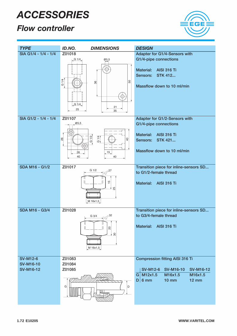
1.72 E10205 WWW.VARITEL.COM
ACCESSORIES
Flow controller
TYPE ID.NO. DIMENSIONS DESIGN
SIA G1/4 - 1/4 - 1/4 Z01018 Adapter for G1/4-Sensors withG1/4-pipe connections
Material: AISI 316 TiSensors: STK 412...
Massflow down to 10 ml/min
SIA G1/2 - 1/4 - 1/4 Z01107 Adapter for G1/2-Sensors withG1/4-pipe connections
Material: AISI 316 TiSensors: STK 421...
Massflow down to 10 ml/min
SDA M16 - G1/2 Z01017 Transition piece for inline-sensors SD... to G1/2-female thread
Material: AISI 316 Ti
SDA M16 - G3/4 Z01028 Transition piece for inline-sensors SD... to G3/4-female thread
Material: AISI 316 Ti
SV-M12-6 Z01083 Compression fitting AISI 316 TiSV-M16-10 Z01084SV-M16-12 Z01085 SV-M12-6 SV-M16-10 SV-M16-12
G M12x1.5 M16x1.5 M16x1.5D 6 mm 10 mm 12 mm
DG
21
35
50
36
G 1
/4
25
G 1/4
G 1/4 ø5,5
27G 1/2
M 16x1,5
15
25
32G 3/4
M 16x1,5
20
30
40
40
15
G 1
/4
G 1
/2
40
26
ø5,5
26

WWW.VARITEL.COM E10205 1.73
CERTIFICATES