catalogue 60hz frequency power factor correction … pfcp 60hz.pdf · catalogue 60hz frequency...
TRANSCRIPT

2015
Metallized paper capacitorsHigh gradient metallized polypropylene capacitors
Standard polypropylene capacitors
LVLVLVC ATA LO G U E
6 0 H z F R E Q U E N C Y POWER FACTORPOWER FACTORPOWER FACTORCORRECTION CORRECTION CORRECTION
QUALITY MADE IN ITALY

newPower Quality in your handswith new regulators RPC 8LGA and 5LGA
Power Quality functions:THD calculation and display of current and voltage.
Powerful.Regulators with poor and confusing displays are a thing of the past: The 8BGA will amaze you with its 128x80 pixel LCD matrix graphic display.The sharp detail allows intuitive navigation of the menus represented by icons and text in the 10 available languages - these include Italian, English, French, German, Russian, Spanish, Portuguese.
Better readabilityof the measures and messages on the screen, thanks to the graphic display, LED and icons.
Alarms descriptionsin six available languages, for better events understanding.
Alarm preventive maintenance,to keep the system always efficient.
Optical portfor adjustment and quick reference by PC using USB cable or WIFI dongle.
RPC 5LGA is on MICROmatic and MINImatic,RPC 8LGA on MIDImatic.
Protection degree IP4X standard for MultimaticThe degree of protection IP4X is no longer an option for MULTImatic PFCS but it is a STANDARD feature, for better reliability and durability of the system. Furthermore, the new cabinet simplifies the maintenance operations, thanks to the easily removable panels.
FREE Warranty ExtensionIt's possible to extend free the warranty for additional 12 months. Applied to all Automatic Power Factor Correction Systems (MICROmatic, MINImatic, MIDImatic, MULTImatic) of the following ranges:
• FH: Power Factor Correction Systems with high energy density• polypropylene capacitors and detuned reactors.• FD: Power Factor Correction Systems with metallized paper capacitors and
detuned reactors• TC: Power Factor Correction Systems with metallized paper capacitors.
To have the extension simply register within 60 days from the delivery date on the web site:www.warranty.icar.com
I
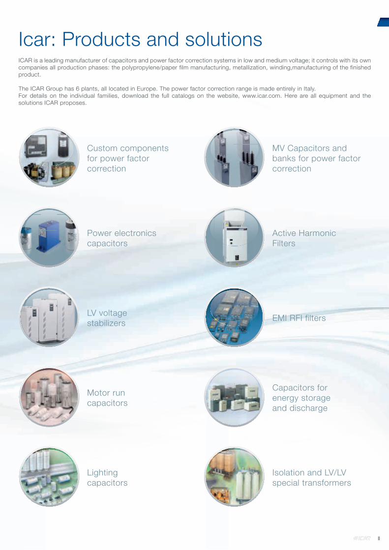
Custom components for power factor correction
MV Capacitors and banks for power factorcorrection
Power electronics capacitors
Active Harmonic Filters
LV voltagestabilizers EMI RFI filters
Motor runcapacitors
Capacitors for energy storageand discharge
Lightingcapacitors
Isolation and LV/LV special transformers
Icar: Products and solutions ICAR is a leading manufacturer of capacitors and power factor correction systems in low and medium voltage; it controls with its own companies all production phases: the polypropylene/paper film manufacturing, metallization, winding,manufacturing of the finished product.
The ICAR Group has 6 plants, all located in Europe. The power factor correction range is made entirely in Italy.For details on the individual families, download the full catalogs on the website, www.icar.com. Here are all equipment and the solutions ICAR proposes.
II

Check-up of existing PFC systems Local support
Tailor madecapacitor banks
Power QualityAssessment
Make your own measurement and let us know
Services For many companies, the electricity is an important cost element, a n d a p a r t o f t h e a m o u n t s i s d u e t o t h e consumption of reactive energy. All companies that distribute electricity are collecting penalties in the bill of consumption, if the user consumes reactive power over the allowed limits.
So today is particularly convenient to install a power factor correction system effectively, correctly sized, which saves a lot of money: a power factor corrector is often pay for itself within a year.
But we must not forget the power factor correction installed for several years: we must monitor the proper functioning because if you do not keep them in perfect working order, they "lose power", and you are likely to pay penalties. With proper maintenance you can avoid wasting money and unnecessary power dissipation in the electric plant cables and transformers that undergoes premature aging.
It is also important a proper maintenance and use of original spare parts since capacitors, when worn or of poor quality, are likely to burst causing damage to electrical equipment, plant shutdowns due to protection tripping, or even real fire.
Our services:• Interventions to verify existing power factor correction
systems.• Interventions on electrical systems analysis and LV
verifi cation to be corrected• Interventions on the start-up and commissioning of
new LV power factor correction banks• Analysis on the energy quality in LV installations• Scheduled maintenance on power factor correction
systems• Revamping solutions• Original spare parts• Analysis of the Energy Authority Penalties
III

Quality ICAR has always regarded product quality and effectiveness of internal processes as key factors of corporate strategy.In ICAR we believe that compliance with international standards is a basic requirement to offer equipment that can meet the needs of our customers.
Quality SystemThe ICAR Quality management system is certif ied according to ISO 9001 since 1994.We participate actively in international standards committees that draft regulations applicable to our production equipment, and in particular to industrial capacitors: this guarantees to be always up with changes in legislation, or rather pre-empt it.
Since 2011 the ICAR quality management system is certified by IRIS (International Railway Industry Standard). Promoted by UNIFE (Association of European companies operating in the railway sector) and supported by operators, system integrators and equipment manufacturers, IRIS integrates the ISO 9001 quality standard introducing additional requirements, specific to the railway industry.
IRIS is modeled on quality standards similar to those already in use in the automotive and aerospace industries.
Independent certification bodies and approved by the promulgators of the
standard ensure object iv i ty and transparency in the evaluation.IRIS certification, while being oriented in the rail sector, has a positive effect on the whole ICAR quality system, with benefits
for all types of produced devices.
The valid certificates can be downloaded from the website www.icar.com the section "Company - Quality"
Product quality The equipment produced in ICAR are tested both in our laboratories and in the most important internationally recognized laboratories, in order to ensure compliance with the highest standards.
The convenienceof power factorcorrection
No more penaltiesThe Electricity Authorities, force companies distributing electricity to apply financial penalties to utilities that have a substantial contractual power and energy cos phi with a lower average of 0,9 or tan phi lower than 0,484.The correct power factor of the
electric plant allows you to avoid those penalties, which often are not reflected in the bill, and then are paid by the final user without even realizing it.
The industrial electric plants are increasingly affected by harmonic currents caused by inverters, electronic drives, computers, filament free lamps, motors with variable speed drives, etc.
The harmonics cause more stress to the power factor correction capacitors: their performance decade by dropping progressively cos phi of the system to below thefateful value of 0,9.You may pay significant penalties... as time goes on!In an electric industrial plant, the installation of a photovoltaic in on-site exchange causes reduction of the power factor seen to the counter.After connection of the photovoltaic electricity, bills may be burdened with significant penalties.
Increased system capacityThe thermal capacity of generators, transformers and cables limit the kVA that can be supplied by the system. Reducing the KVAR demand from existing load by installing capacitors, allows additional load to be added to the system.
Improved voltageHigh demand of reactive power increases the voltage drops across transformers, cables and other system components. The result is a decreased utilization voltage.The voltage drops can be limited by increasing the power factor.
Reduced circuit lossesSince current is reduced in direct proportion to the increase in power factor, the resistive losses, in the circuit, are inversely proportional to the power factor. The increase of power factor allows a losses reduction with substantial benefits for the system.
Certificato UNI EN Iso9001:2008
IV

Steps aboard an automatic power factor corrector. They are the physical units of power factor bank, each controlled by a dedicated switching device (static switch or contactor). A rack may be constituted by a single step (as typically occurs in detuned bank) or more steps. For example, the MULTIrack HP10 from 150kvar/400V consists of 6 steps: 2 from 15kvar and 4 from 30kvar. It 'is easily verified by counting the number of contactors present on the front of the drawer. More step can be merged to achieve larger power steps: in these cases they are controlled by the same controller contact.
Combinations. It is the internal configurations number which proposes a particular automatic power factor corrector, as a function of the steps (number and power) that has on board. For example, a power factor corrector of 280kvar with steps 40-80-160 offers 7 combinations: 40-80-120-160-200-240-280.The greater the number of possible combinations, the better "accuracy" and the flexibility to use the power factor correction bank.
THD (Total Harmonic Distortion).For a periodic non-sinusoidal wave, the THD is the ratio between the rms of all harmonic components value and the rms value of the fundamental at 50Hz.
THDIc. It is the harmonic overload suggested in order to satisfy the technical requirements of the components.It is a characteristic value of each capacitor, indicative of its robustness: much higher is the THDIC, more robust isthe capacitor. The THDIC is the most significant value to compare different capacitors, together with the maximumtemperature of use.
THDIR. It is the maximum THD present in the plant without any capacitor battery installed on the basis of which to select the type of the capacitor to be installed in the plant. It is an empirical fact, based on the construction technology used and the experience of the manufacturer.There is no theoretical link between THDIR and THDIC valid for all plants. The THDIR can also be very different, for capacitors with the same THDIC produced by different manufacturers, depending on the risk tolerance of the manufacturer.
THDV. It is the voltage THD bearable by a power factor correction bank with harmonic blocking reactors.
fN: is the detuning frequency between inductance and capacitance of a detuned capacitor bank, that is a capacitor bank equipped with harmonic biocking reactors. The detuning frequency is the most objective parameter for detuned capacitor bank comparison; the lower the detuning frequency is the sounder the capacitor bank is.In particular an 180Hz detuned capacitor bank is sounder and more reliable than another with 189Hz detuning frequancy fN.As of Ferranti effect, detuned capacitor bank capacitors are exposed to a voltage that is higher than the rated system voltage; for this reason these capacitors are rated for higher voltage according to the p% factor.
Cos Phi. Simplifying, in an electrical system is appointed with phi (φ), the phase shift between the voltage and the electric current at the fundamental frequency of the system (50Hz). The cos phi is therefore a dimensionless number between 0 and 1, and varies from moment to moment. Typically, an industrial electrical system has an inductive cos phi, which value depends on the characteristics of the user plant.
Power factor. In an electrical system means, with power factor, the ratio between the active power and the apparent power. Also the power factor is a dimensionless quantity between 0 and 1, which varies from moment to moment. However, the cos phi and the power factor coincide only in systems devoid of sinusoidal harmonic currents. In a system with harmonic, the power factor is always less than the cos phi.
Monthly average power factor.Electricity bills often show the monthly average power factor, obtained from the ratio between the active power consumed by the user and the apparent power transited the point of delivery. Typically, the average monthly power factor is calculated separately on different time slots.
Penalty for low power factor.If the monthly average power factor is less than 0,9 lagging, are applied in the bill some financial penalties.
Isolation level. For a capacitor that complies with IEC 61921, the isolation level is indicative of the voltage pulse that can withstand.
Insulation voltage. For a power factor correction system that complies with the IEC 60439-1/2, the isolation voltage is indicative of the maximum voltage that can withstand the entire system.
Nominal voltage of the capacitor UN.It is the rated voltage of the capacitor, at which its output rated power is calculated.
Maximum operating voltage UMAX.It is the maximum voltage that the capacitor can withstand, for the time indicated by the IEC 60831-1/2.The following relation applies UMAX = 1,2 UN.
Rated operational voltage Ue.It is the rated voltage of the power factor correction system, which guarantees proper use. A capacitor with a rated voltage can have on board capacitors with voltage UN> UE. It may never happen otherwise.
Short-circuit current Icc.As indicated in the IEC 61439-1 Article 3.8.9.4, is the prospective short-circuit current that the cabinet can endure for a specified time. It's a value stated by the manufacturer of the cabinet on the basis of laboratory tests. The short-circuit current of the cabinet can be increased, in case of need, by installing fuses. In this case the declared data must be accompanied by the words "fuse conditioning short-circuit current."
Glossary
V

SummaryCHAPTER 1 Power factor correction principles 1
CHAPTER 2 Selection criteria depending on the type of plant 8
CHAPTER 3 Power factor correction. Solutions with standard or high gradient metallized polypropylene capacitors 16
CHAPTER 4 Power factor correction. Solutions with metallized paper capacitors 28
CHAPTER 5 Reactive power controllers and protections 32
CHAPTER 6 Dimensions 38
APPENDIX 45
VI

Power Factor Correction PrinciplesPower factor correction: why?In electrical circuits the current is in phase with the voltage whenever are in presence of resistors, whereas the current is lagging if the load is inductive (motors, transformers with no load conditions), and leading if the load is capacitive (capacitors).
V I
Φ=0°
V
I
Φ=90°lag
V
I
Φ=90°lead
The total absorbed current, for example, by a motor is determined by vector addition of:
1. IR resistive current;2. IL inductive reactive current;
V
IL
IR
Φ
I
Cos φ =I R
I
These currents are related to the following powers:1. active power linked to IR; 2. reactive power linked to IL;
The reactive power doesn’t produce mechanical work and it is an additional load for the energy supplier.The parameter that defines the consumption of reactive power is the power factor. We define power factor the ratio between active power and apparent power:
FP =P
A
A = P2 + Q2P
A Q
Φ
As far as there are not harmonic currents power factor coincides to cosφ of the angle between current and voltage vectors. cosφ decreases as the reactive absorbed power increases.Low cosφ, has the following disadvantages:
1. High power losses in the electrical lines2. High voltage drop in the electrical lines3. Over sizing of generators, electric l ines and
transformers.From this we understand the importance to improve (increase) the power factor. Capacitors need to obtain this result.
Power factor correction: how?By installing a capacitor bank it is possible to reduce the reactive power absorbed by the inductive loads in the system and consequently to improve power factor.It is suitable to have cosφ a little in excess of 0.9 to avoid paying the penalties provided for by the law. cosφ must not be too close to unity, to avoid the leading currents in of the electrical system.The choice of the correct power factor correction equipment depends on the type of loads present and by their way of working.The choice is between CENTRAL COMPENSATION and INDIVIDUAL COMPENSATION.Individual compensation: power factor correction is wired at each single load (i.e. motor terminals)Central compensation: there is only one bank of capacitors on the main power distribution switch board or substation.
Individual Compensation Central Compensation
The individual compensation is a simple technical solution: the capacitor and the user equipment follow the same sorts during the daily work, so the regulation of the cosφ becomes systematic and closely linked to the load.Another great advantage of this type of power factor correction is the simple installation with low costs.The daily trend of the loads has a fundamental importance for the choice of most suitable power factor correction.In many systems, not all the loads work in the same time and some of them work only a few hours per day.It is clear that the solution of the individual compensation becomes too expensive for the high number of capacitors that have to be installed. Most of these capacitors will not be used for long period of time.The individual compensation is more effective if the majority of the reactive power is concentrated on a few substatios loads that work long period of time.Central compensation is best suited for systems where the load fluctuates throughout the day.If the absorption of reactive power is very variable, it is advisable the use of automatic regulation in preference to fixed capacitors.
CHAPTER 1
1

Power factor correction:How many capacitors?The choice of capacitor bank to install in a system is closely depended from:
• cosφ2 value that we would obtain• cosφ1 starting value• installed active power.
By the following equation:
Q C = P * (tanφ1 - tanφ2 )
P
A
A’ QL’
QL QC
1 2
Can be also written Q c = k * P
where the parameter k is easily calculable using table 1 below andQC = Required Capacitors Reactive Output [kvar];P = Active Power [kW];QL, Q’L = Inductive Reactive Output before and after the installation of the capacitor bank;A, A’= apparent power before and after the power factor correction [kVA].
As example if we have installed a load that absorbs an active power of 300 kW having a power factor 0.7 and we want toincrease it until 0.95.From the table 1 we fi nd: k = 0,692
Which means: Q c = 0,692 * 300 = 207,6 kvar
Starting power factor
Final power factor
0,9 0,91 0,92 0,93 0,94 0,950,40 1,807 1,836 1,865 1,896 1,928 1,9630,41 1,740 1,769 1,799 1,829 1,862 1,8960,42 1,676 1,705 1,735 1,766 1,798 1,8320,43 1,615 1,644 1,674 1,704 1,737 1,7710,44 1,557 1,585 1,615 1,646 1,678 1,7120,45 1,500 1,529 1,559 1,589 1,622 1,6560,46 1,446 1,475 1,504 1,535 1,567 1,6020,47 1,394 1,422 1,452 1,483 1,515 1,5490,48 1,343 1,372 1,402 1,432 1,465 1,4990,49 1,295 1,323 1,353 1,384 1,416 1,4500,50 1,248 1,276 1,306 1,337 1,369 1,4030,51 1,202 1,231 1,261 1,291 1,324 1,3580,52 1,158 1,187 1,217 1,247 1,280 1,3140,53 1,116 1,144 1,174 1,205 1,237 1,2710,54 1,074 1,103 1,133 1,163 1,196 1,2300,55 1,034 1,063 1,092 1,123 1,156 1,1900,56 0,995 1,024 1,053 1,084 1,116 1,1510,57 0,957 0,986 1,015 1,046 1,079 1,1130,58 0,920 0,949 0,979 1,009 1,042 1,0760,59 0,884 0,913 0,942 0,973 1,006 1,0400,60 0,849 0,878 0,907 0,938 0,970 1,0050,61 0,815 0,843 0,873 0,904 0,936 0,9700,62 0,781 0,810 0,839 0,870 0,903 0,9370,63 0,748 0,777 0,807 0,837 0,870 0,9040,64 0,716 0,745 0,775 0,805 0,838 0,8720,65 0,685 0,714 0,743 0,774 0,806 0,8400,66 0,654 0,683 0,712 0,743 0,775 0,8100,67 0,624 0,652 0,682 0,713 0,745 0,7790,68 0,594 0,623 0,652 0,683 0,715 0,7500,69 0,565 0,593 0,623 0,654 0,686 0,7200,70 0,536 0,565 0,594 0,625 0,657 0,6920,71 0,508 0,536 0,566 0,597 0,629 0,6630,72 0,480 0,508 0,538 0,569 0,601 0,6350,73 0,452 0,481 0,510 0,541 0,573 0,6080,74 0,425 0,453 0,483 0,514 0,546 0,5800,75 0,398 0,426 0,456 0,487 0,519 0,5530,76 0,371 0,400 0,429 0,460 0,492 0,5260,77 0,344 0,373 0,403 0,433 0,466 0,5000,78 0,318 0,347 0,376 0,407 0,439 0,4740,79 0,292 0,320 0,350 0,381 0,413 0,4470,80 0,266 0,294 0,324 0,355 0,387 0,4210,81 0,240 0,268 0,298 0,329 0,361 0,3950,82 0,214 0,242 0,272 0,303 0,335 0,3690,83 0,188 0,216 0,246 0,277 0,309 0,3430,84 0,162 0,190 0,220 0,251 0,283 0,3170,85 0,135 0,164 0,194 0,225 0,257 0,2910,86 0,109 0,138 0,167 0,198 0,230 0,2650,87 0,082 0,111 0,141 0,172 0,204 0,238
Table 1See the full table in Appendix
2

A typical example of power factor correction, sometimes not much considered but surely important, concerns the power factor correction of transformers for the distribution of energy. It is essentially a fi xed power factor correction that must compensate for the reactive power absorbed by the transformer in its no load condition (this happens often during the night). The calculation of the needed reactive output is very easy and it bases itself on this equation:
A N
100Q c = I 0 % *
whereI0%= magnetising current of the transformerAN= Apparent rated power in kVA of the transformer
If we don’t have these parameters, it is convenient to use the following table.
Power transformerKVA
Oil transformer kvar
Resin transformer
kvar10 1 1,5
20 2 1,7
50 4 2
75 5 2,5
100 5 2,5
160 7 4
200 7,5 5
250 8 7,5
315 10 7,5
400 12,5 8
500 15 10
630 17,5 12,5
800 20 15
1000 25 17,5
1250 30 20
1600 35 22
2000 40 25
2500 50 35
3150 60 50
Table 2
Another very important example of power factor correction concerns asynchronous three-phase motors that are individually corrected. The reactive power likely needed is reported on table 3:
Motor power Required Reactive Power (kvar)
HP kW 3000 rpm
1500 rpm
1000 rpm
750 rpm
500 rpm
0,4 0,55 - - 0,5 0,5 -
1 0,73 0,5 0,5 0,6 0,6 -
2 1,47 0,8 0,8 1 1 -
3 2,21 1 1 1,2 1,6 -
5 3,68 1,6 1,6 2 2,5 -
7 5,15 2 2 2,5 3 -
10 7,36 3 3 4 4 5
15 11 4 5 5 6 6
30 22,1 10 10 10 12 15
50 36,8 15 20 20 25 25
100 73,6 25 30 30 30 40
150 110 30 40 40 50 60
200 147 40 50 50 60 70
250 184 50 60 60 70 80
Table 3
Be careful: the capacitor output must not be dimensioned too high for individual compensated machines where the capacitor is directly connected with the motor terminals. The capacitor placed in parallel may act as a generator for the motor which will cause serious overvoltages (self-excitation phenomena). In case of wound rotor motor the reactive power of the capacitor bank must be increased by 5%.
Power factor correction: technical reasonsRecent energy market deregulation, along with new potential energy supplier rising, had lead to many and different type of invoicing which are not very clear in showing Power Factor up.However as energy final price is steady growing, to correct power factor is becoming more and more convenient.In most of the cases power factor improvement device prime cost is paid back in few months. Technical-economical advantages of the installation of a capacitor bank are the following:
• decrease of the losses in the network and on the transformers caused by the lower absorbed current
• decrease of voltage drops on lines• optimisation of the system sizing.
The current I, that flows in the system, is calculated by:
I =P
3 * V * cosφ
whereP= Active powerV= Nominal VoltageWhile cosφ increases, with the same absorbed power we can obtain a reduction in the value of the current and as a consequence the losses in the network and on the transformers are reduced. Therefore we have an important saving on the size of electrical equipment used on a system. The best system sizing has some consequence on the line voltage drop. We can easily see that looking at the following formula:
PV
QV∆V = R * + X *
whereP= active power on the network (kW)Q= reactive power on the network (kvar)while R is the cable resistance and X its reactance (R<<X). The capacitor bank installation reduces Q so we have a lower voltage drop. If, for a wrong calculation of the installed capacitor bank value, the reactive part of the above equation becomes negative, instead of a reduction of the voltage drop we have an increasing of the voltage at the end of the line (Ferranti Effect) with dangerous consequence for the installed loads. Some examples clarify the concepts set out above:
1. Power loss (kW), in function of cosφ, from a copper cable 3 x 25mm2 100m long carrying 40kW at 400Vac.
2. Supplied active power (kW) by a transformer 100kVA, in function of cosφ
cos φ 1) 2)0,5 3,2 50
0,6 2,3 60
0,7 1,6 70
0,8 1,3 80
0,9 1 90
1 100
As we can see as the power factor increases we have fewer losses in the network and more active power from the same KVA.This allows us to optimise on the system sizing.
3

Power factor correction:Harmonics in the network The distortions of the voltage and current waveforms are generated by non-linear loads (inverter, saturated transformers, rectifi er, etc.) and produce the following problems:
• On the A.C. motors we find mechanical vibration that can reduce expected life. The increase of the losses creates overheating with consequent damaging of the insulating materials;
• In transformers they increase the copper and iron losses with possible damaging of the windings. The presence of direct voltage or current could cause the saturation of the cores with consequent increasing of the magnetising current;
• The capacitors suffer from the overheating and the increasing of the voltage that reduce their life.
The waveform of the current (or voltage) generated by a non-linear load (fi g. 1), being periodical, could be represented by the sum of many sinusoidal waves (a 50Hz component called fundamental and other components with multiple frequency of the fundamental component so called HARMONICS).
I = I1 + I2 + I3 + I4 + ...In
It is not advisable to install the power factor correction without considering the harmonic content of a system.This is because, even if we could manufacture capacitors that can withstand high overloads, capacitors produce an increase of harmonic content, with the negative effects just seen. We speak about resonance phenomena when an inductive reactance is equal to the capacitive one:
12πf C
2πf L =
LLLcccc C
Ih
Ihc
Ihl
=~ =
~
M
No linearload
Capacitor
Transformer
Ideal current generator represents motor as harmonic current components generator, these are independent from circuit inductance, while LCC is obtainable by capacitor upstream short circuit power (in general it is equal to transformer short-circuit inductance) the resonance frequency is obtained as follows:
N =Scc
QA * 100Q * vcc%
=~
Scc = Short-circuit power of the network (MVA)
Q = Output of power factor correction bank (kvar)
A = Rated power transformer (kVA)
vcc% = Short-circuit voltage %
N = Resonance harmonic order
In parallel resonance conditions the current and the voltageof the circuit LCC - C are heavily amplified as well as thenearby harmonic currents. Hereinafter an example:
A = 630kVA (rated power transformer)
Vcc% = 6 (shot-circuit voltage %)
Q = 300kvar (output of power factor correction bank)
=~N = 6A * 100Q * vcc%
630 * 100300 * 6
=
The result shows that in these conditions the system transformer-capacitor bank has the parallel resonance frequency of 300Hz (Nx50Hz). This means likely amplifi cation of 5h and 7th harmonic current.The most convenient solution to avoid this is the detuned filter, formed introducing a filter reactor in series with the capacitors, making this a more complex resonant circuit but with the desired feature of having a resonance frequency below the first existing harmonic.
LLLccc
C
IhIcItLf
=~ =
~
MNo linear
load
Detuned capacitor bank
Transformer
With this type of solution, the parallel resonance frequency is modified from
f rp =1
toLcc * C2 * π *
f rp =1
(Lcc + Lf) * C2 * π *
4

Normally the resonance frequency between the capacitor and the series reactance is shifted lower than 250Hz and it is generally between 135Hz and 210Hz. The lower frequencies correspond to higher harmonic loads.The installation of a reactance in series with the capacitor bank produces a series resonance frequency:
f rs =1
L f * C2 * π * If a harmonic current Ih with the same frequency of the resonance in series exists, this one will be totally absorbed by the system capacitors - reactors without any eff ect on the network. The realisation of a tuned passive filter is based on this simple principle. This application is required when we want the reduction of the total distortion in current (THD) on the system:
THD = I 3 + I 5 + I 7 + ....I n2 2 2 2
I 1
I1 = Component at the fundamental frequency (50Hz) of the total harmonic current
I3 , I5… = Harmonic components at the multiple frequency of the fundamental (150Hz, 250Hz, 350Hz, ...)
The dimensioning of tuned/passive fi lters is linked to the circuit parameter:
• impedance of the network (attenuation effect less as the short-circuit power on the network increases: in some cases could be useful to add in series with the network a reactance to increase the filtering effect);
• presence of further loads that generate harmonics linked to other nodes on the network
• capacitor types;
On this last point we have to make some considerations.It is known that the capacitors tend to decrease capacity over time: varying the capacity inevitably varies the resonance series frequency
f rs =1
L f * C2 * π * and this drawback can be very dangerous because the system could lead in parallel resonance conditions. In this case, the fi lter does not absorb more harmonics but even amplifi es them. In order to have a constant capacity guarantee over time we need to use another type of capacitors made in bimetallized paper and oil impregnated polypropylene. In addition to the passive absorption fi lter realized with capacitors and inductances is possible to eliminate the network harmonics, with another type of absorption fi lter: the Active Filter. The operation principle is based on the in-line injection of the same current harmonics produced by non-linear loads, but out of phase.
Power factor correction in presenceof distorted voltageIn many industrial electrical systems or in the tertiary sector, the presence of non-linear loads (inverter, welding, fi lament free lamps, computers, drives, etc..) causes a distortion of the current, which is synthesized by the THDI% numeric parameter: if the current is sinusoidal his THDI% is zero, more the current is deformed so much higher is its THDI%. In electrical currents with very deformed currents, the power factor correction equipment are carried out in a "fi lter banks" (or "block" or "blocked" or "detuned" if you prefer), or rather with inductors that prevent harmonic current to reach and damage the capacitor.Usually the supply voltage remains sinusoidal even if a very deformed current fl ows in the plant; however, if the MV/LV transformer impedance is high, the voltage may also
be aff ected by deformation: this impedance, crossed by a distorted current, will create a voltage drop equally distorted, causing on LV users a non-sinusoidal supply voltage (or with a certain THDV%). It is rare that the THDV% reaches 8% (limit of IEC EN 50160), this happens for example when the MV/LV transformer is characterized by a high series impedance and/or is overloaded (saturation).In a plant with distorted voltage there will be problems of various types, depending on the utilities (breakage or malfunction of electronic parts such as relays, plc, controller, computers; production beyond the acceptable tolerances, etc.). Regarding the power factor correction, a high THDV% creates problems for the blocking reactors used in power factor correction banks. These can saturate and overheat for overload up to be damaged, causing the out of service of the power factor correction bank and/or problems to the capacitors. This will result in an economic loss (payment of penalties for low cos phi) and technical, because the plant will run through by a higher current, resulting in conductors additional overhead (cables, bars) and the transformer. For this problem, ICAR has developed a dedicated solution: the MULTImatic FD25V (for 400V network) and FD70V (for 690V network) power factor correction ranges. They are made with sound heavy duty-bimetallized paper capacitors with high performance electronic instrumentation for the electrical parameters control; high linearity reactance allow them to bear up to 8% THDV continuously.
Power factor correction in the presence of a photovoltaic system in spot tradingIf on electrical plant of an industrial user is added a photovoltaic system, the active power drawn from the supply is reduced because of the power supplied by the photovoltaic system and consumed by the plant (consumption).Therefore, it changes the relationship between reactive power and active energy drawn from the network and, consequently, the power factor is lower than the same system without photovoltaic. We must therefore pay particular attention to the power factor correction not to have any penalties for low cos phi that could seriously erode the economic benefi ts of the photovoltaic system.The power factor correction will be reviewed both for installed capacity, both for construction type. In fact, increasing the power factor corrector power, you will modify the resonance conditions with the MV/LV transformer which supply the system. When the photovoltaic system has more power than the users one, or if it is possible that power is introduced to the network, the power factor corrector must also be able to run on the four quadrants. The two "standard" quadrants are related to the plant operation as a user that absorbs from the network both active and inductive reactive power, while the two quadrants related on the plant functioning as a generator, it provides the network active power, but it absorbs the inductive reactive power (quadrants of generation).
All ICAR range of cos phi electronic controllers are able to operate in four quadrants, running two diff erent cos phi targets to optimize the system economic performance. To manage the cogeneration quadrants you can alter some parameters settings. It is advisable to enter a value equal to 1, to optimize the yield of the PFC Bank. Refer to the manuals of the controllers for more details. To get the maximum benefi t in the time allowed by the PFC Bank, we recommend to use bimetallized paper capacitors, the only ones that guarantee a useful life comparable to the photovoltaic system one.
5

Power factorcorrection:quality and safetyBasic requirement
We defi ne safety the absence of dangers for people and things while the good is in use or stored in a warehouse. This means to identify stresses, risks and potential damages and the relevant elimination and to keep them under control so that to reduce the risk to a reasonable level.Power capacitors and capacitor banks shall not be used:
• For uses other than Power Factor Correction and for AC or DC plants.
• As tuned or detuned fi lters unless specifi cally approved in written by ICAR
General requirementThe capacitors are constructed in accordance with IEC – CEI EN methods, parameters and tests. The low voltage capacitors are assembled with the required protection devices and assembled into banks to give a QUALITY product which will operate SAFELY. They are not considered as the indication that the capacitors and the power factor correction equipments are suitable for a use in the same conditions of the tests. The user has to verify that the capacitor and power factor correction equipment are of the correct voltage and frequency suitable for values of the network on which they are installed. The user has to verify that the installation of the capacitors and/or the power factor correction equipment is in accordance with the catalogue and the instructions of use. Capacitors and power factor correction equipment MUST NOT be exposed to damaging action of chemical substance or to attacks of fl ora and/or fauna. Capacitors and power factor correction equipments must be protected against risks of mechanical damaging to which could be exposed during normal working conditions or during the installation. Capacitors and power factor correction equipments that were mechanically or electrically damaged for any reason during the transport, the storage or the installation must not be used and these that breakdown during use must be immediately removed.
Additional instructions about power factor correction equipmentsDefi nition Power factor correction equipment means:
• one or more groups of capacitors that can be connected and disconnected on the network automatically or manually using suitable operating devices (contactors, circuit breakers, load-break switch, ...)
• operating devices• control, protection and measure systems• connections
The equipment could be open or closed inside a metal enclosure. General requirement Follow ICAR instructions in the documentation attached to equipments considering the safe distance, the connection standard criteria, working standards and the instructions for the controls and the maintenance. Compatibility It must be paid attention to the electromagnetic interferences with the near by equipments. Contactors It is advisable to adopt capacitor duty contactors (category AC6-b) because they are equipped with pre charge resistors that substantially reduce the inrush currents while capacitors are switched on. The early switching on of these resistors in respect
to the closing or the contactor contacts, allows:• To avoid main contacts melting.• To avoid capacitor damage.
Recommendations for installationFixing and connection To fix the power factor correction equipments it is advised to use these types of screws:
• Riphaso series with M10 screw• MICROmatic and MICROfi x series wall-mounted with FISHER 8• MINImatic wall-mounted and fl oor-mounted with M8 screw• MULTImatic and MULTImatic HLP fl oor-mounted with M12
screw. The installation of the power factor correction equipment is for indoor application; for different use call ICAR technical department. Protection devices Operating devices (load-break switch) or operation and protection (circuit-breakers if the cables are longer than 3m) must be dimensioned to withstand capacitive currents (about 1.3 times nominal current), the inrush currents, the number of operations and they must be re-strike free.The capacitors are made of polypropylene that is a fl ammable material. Even if a fi re doesn’t begin from capacitors or inside the panel, they could however spread it creating dangerous gasses. If a danger exists from the presence of an explosive or fl ammable atmosphere, the IEC standard; ”Electric equipment with explosion and fi re danger”, shall be strictly followed. Danger for people When we install power factor correction equipment we must pay attention that the parts which could be exposed to voltage are correctly protected from accidental contacts in accordance with IEC standards. Before the commissioning verify the tightening of the terminal and of all the bolts is correct.
Protections Fuses and overpressure disconnector All the capacitors have an overpressure device which when operated, as in the case of breakdown, disconnects the element from use. This device is not a substitution for the fuses or external circuit-breakers that are specified in our power factor correction equipment.
Limit conditions The infl uence of each factor below has not to be considered individually, but in combination and with the influence of other factors. Voltage Capacitor and capacitor bank nominal voltage is intended as the design and testing voltage.The safe and proper use of power factor correction capacitors and capacitor banks, implies that the working voltage is not higher than the nominal voltage.In special conditions, excluding the installation phases, higher over voltage are allowed as per below table (ref. IEC 60831).
Overvoltage factor(x UN eff )
Max. duration Observations
1 Continous Highest average value during any period of ca-pacitor energization. For energization period less than 24h, exceptions apply as indicated below
1,10 8h every 24h System voltage regulation and fl uctuation
1,15 30 min. every 24h System voltage regulation and fl uctuation
1,20 5 min Voltage rise at light load
1,30 1 min
Note: for voltage without harmonics
6

The life expectancy of capacitors and power factor correction equipment is greatly reduced when operating in overload conditions. The choice of the nominal voltage is determined by the following considerations:
• On some networks working voltage could be very diff erent from nominal voltage
• Power factor correction equipment in parallel could cause an increase of the voltage at the connection point
• The voltage increases with the presence of harmonics on the network and/or cosφ of in advance
• The voltage at the capacitor terminals increases when capacitors are in series with reactors for harmonic blocking.
• If the power factor correction equipment is connected to a motor and not sized correctly, when we disconnect it from the network we may have a phenomena caused by the inertia that makes the motor to work as a self-excited generator consequently increasing of the voltage level at the terminals of the equipment
• The remaining voltage caused by the self-excited after that the equip- ment has been disconnected from the network is dangerous for the generators
• If the power factor correction equipment is connected to a motor with a star-delta starting device we have to pay attention to not cause the overvoltage when this device is working
• All the power factor correction equipments exposed to overvoltage caused by atmospheric lightning must be protected in correct way. If surge arrestors are use they have to be placed as near as possible to the equipment.
Working temperature Working temperature of power factor correction equipment is a fundamental parameter for safe operation. As a consequence it is very important that heat generated is dissipated correctly and that the ventilation is such that the heat losses in the capacitors do not exceed the ambient temperature limits. The highest workings temperature in normal service conditions between two capacitors is measured at a point 2/3 of the capacitors height and at a distance of 0.1m from them. The capacitor temperature must not exceed the temperature limits hereinafter tabled.
Symbol
Ambient temperatures (°C)
Maximum
Highest mean over any period of:
24h 1 year
A 40 30 20
B 45 35 25
C 50 40 30
D 55 45 35
Mechanical Limits The user has not to expose the equipment to exaggerated mechanical limits of operation. The user has to pay attention to the electrical and geometrical dimensioning of the connections to avoid exceeding the mechanical limits which may be reached by temperature variation.
Other considerations for the workingsafetyDischarge device Every capacitor must have a discharge device that can discharge it within 3 minutes. The discharge time is calculated from the starting peak of voltage equal to VN until 75V. Between the capacitor and the discharge system there shall not be a circuit-breaker, fuses or other sectioning devices.This doesn’t relief to short-circuit the capacitor terminals and earth every time it is required to handle the capacitor.Residual voltage When the capacitor is placed under tension its residual voltage
must not exceed 10% of the rated voltage. This condition is generally satisfi ed when the power factor correction equipment is calibrated properly, the reactive power controller, reconnection time shall be appropriate to the discharge time. Case connection To keep capacitors case at fi x voltage and to discharge fault current toward the case itself, they are grounded by connecting to earth the capacitors supporting frame. Altitude Power factor correction equipment must not be used above an altitude of 2000m. On the contrary please contact technical assistance of ICAR S.p.A. Particular ambient conditions Power factor correction equipment are not suitable for the applications in places where there are conditions as follows:
• Fast generation of mould• Caustic and saline atmosphere• Presence of explosive materials or very fl ammable• Vibrations
For environments with these characteristics: high relative humidity, high concentration of dust and atmospheric pollution, please contact technical assistance of ICAR S.p.A.
Maintenance After the disconnection of the bank, prior to accessing the terminals of the capacitors wait 5 minutes and then short-circuit the terminals and earth. Make these procedures: Once a month:
• Cleanliness by blast of air of the internal part of the power factor correction equipment and of the air fi lter anytime there is a cooling system
• Visual control• Control of the ambient temperature.
Once every 6 months: • Control of the surfaces condition: painting or other
treatments• Control of the correct tightening of the screw (this
operation must be done before the commissioning). If there are concerns about any environmental conditions an appropriate maintenance program must be established (for example in a dusty environment could be necessary to clean using blasts of air more frequently).Once a year
• Checking the contactors status • Checking the capacitors status
Storage and handlingThe power factor correction equipment handling must be made carefully avoiding the mechanical stresses and shocks.The equipment in highest cabinet may be hard to handle, because the center of gravity may be very high and decentralized.Upon receipt of new equipment, make sure that the packaging is not damaged, although mild. Always make sure that the equipment has not been damaged by transportation: take away the packaging and make a visual inspection with open door. If you discover some damage, write it on the delivery note (carrier copy) the reason for refusal or reserve.
The capacitors and power factor correction awaiting installation storage must be done leaving them in their original packaging, in a covered and dry place.
For more detail refer to specifi c product user's Manual.
7

Selection criteria Capacitors used in power factor correction solutionsIn our power factor correction systems we only use our capacitors production, made entirely from ICAR: in this way, we can offer to our customers the highest guarantee of the equipment reliability. The capacitors used are divided into three different types, which lead to electrical and thermal performance completely different:
Our paper bimetallized capacitors are, today, the most imitated... but just look at the construction characteristics detail of what is proposed as "3In" or "4In" to realize that they are simple polypropylene capacitors, maybe just a little '"strengthened".
By their nature, they cannot even come close to the technology "bimetallized paper" performance, especially as regards the maximum operating temperature.Summing up, the main diff erent types of capacitors features are shown in the table below.
Capacitortechnology
Lifeexpectancy
Loss ofcapacitance
Voltage withstand
Allowedcurrent
overload
Peakcurrent
withstand
Overallreliability
Maximumworking
temperatureStandard
polypropylenevery good low good good good good 55°C
High voltagepolypropylene
very good low excellent very good very good very good 55°C
Metallizedpaper
excellent negligible very good excellent excellent excellent 70°C
Maximum working temperature is meant capacitor sorrounding air temperature.
Polypropylenestandard capacitors
They are made by wrapping a metallized polypropylene film.In function of the film thickness, the layer of metal deposited on the surface and the number of windings made, you get the desired characteristics of capacity, rated voltage, withstand overcurrents etc.According to the characteristics, the polypropylene standard capacitors are used in power factor correctors SP20, RP10, RP20 families.
High gradientmetallized
polypropylene capacitors The substantial difference with the standard polypropylene capacitors is the mode with which the dielectric film is metallized: if in the standard capacitors the metal layer thickness deposited on the surface of the film is constant, for those "high gradient" the metal layer has a suitably modulated thickness.The metallization thickness modulation allows to greatly improve the capacitors (and therefore of the power factor correction systems which are the fundamental component) in terms of:
• Increase in power density (kvar/dm3) with a consequent power size reduction of the power factor correction systems;
• Robustness improvement against voltage surges, for greater reliability even in systems with the presence of voltage fluctuations due to the network or maneuvers on the system;
• Improved behavior of the internal short circuit withstand.
According to the characteristics, the metallized polypropylene capacitors are used in high gradient power factor correctors HP10, HP20, HP30, FH20 and FH30 families.
Bimetallized papercapacitors
The bimetallized and impregnated paper capacitors are now the most robust solution for industrial power factor correction.They are made by wrapping a thin sheet of special paper on the surfaces of which is deposited by evaporation process, a infi nitesimal layer of metal alloy with function of electrode; between the sheets of paper is placed a polypropylene fi lm with only the dielectric role between electrode. The bimetallized paper capacitors robustness is due to the already excellent mechanical paper characteristics, to which are added the impregnation in oil benefi ts. This technology, among the most tested for the capacitors production, was also adopted to realize capacitors used in power electronics, since solicited with high frequencies and designed to work with high temperatures.The ICAR bimetallized paper capacitors are particularly suitable for applications in plants with high harmonic content currents and/or high operating temperatures; they are used for the detuned fi lters realization for "troubled" installations because, thanks to the steady capacitance throughout the useful life, these capacitors are able to keep in time the tuning of the fi lter frequency, even in high operating temperatures presence.In function of the characteristics, the bimetallized paper capacitors are used in TC10,TC20, FD25, FD35, etc. families.
CHAPTER 2
8

MICROmaticIt is the smaller size of automatic power factor correction bank, suitable for small users power factor correction. It is made with modular concept (MICROrack) to simplify the management of spare parts and maintenance. For reactive power up to 64kvar at 400V in very small dimensions. Allows you to have up to 19 steps for optimal power factor correction in the presence of highly variable loads or characterized by long periods of "no load" operation.The HP10 family is also available in FAST version for small loads fast power factor correction (lifts, elevators, car washes, etc.).
MINImaticFor small/medium powers automatic power factor correction, can deliver up to 225kvar 400V, depending on the version. Is made with completely removable rack (MINIRack) to simplify management and maintenance. Very flexible Framework, allows the realization of many variations as shown in the available options table. MINImatic is also available in a version with harmonic blocking reactors and cable entry from bottom.
MULTImaticPower factor correction automatic for large users, allows systems of up to several Mvar, with master-slave logic. MULTImatic is made rack (MULTIrack) for easy replacement and maintenance. It is available in SPEED series (for fast loads), detuned or tuned, in the degrees of protection, IP 4X, IP55, with cable entry from top or bottom. The distribution of power is with robust copper bars.Frameworks of standard equipments made from multiple columns side by side are equipped with a disconnector and a cable entry in each column. ICAR can make framework on multiple columns with one single cable entry.
CRTEThe simplest and most efficient fixed power factor correction is three-phase capacitor.Available from 1kvar to 50kvar at 400V or higher voltages (up to 800V). See dedicated catalog.
MICROfixPower factor correction for fixed three-phase systems, in metal enclosure with IP3X protection degree.MICROfix is equipped with a integrated door lock isolating switch, signal lamps and fuses. For power up to 60kvar at 400V.
FIX POWER FACTORCORRECTION SYSTEMS
AUTOMATIC POWER FACTORCORRECTION SYSTEMS
9

Automatic Capacitor Banks Standard featuresThese are the common features to all automatic banks: PFC regulator with temperature control, IP3X degree of protection (IP4X for MULTImatic), RAL 7035 cabinet paint color, Working voltage Ue of 400V*.
MICRO matic MINI matic MULTImatic
Cable incoming top/bottom top bottom
Ventilation forced forced forced
PFC controller RPC 5LGA RPC 5LGA RPC 8BGA
* For Ue working voltage other than 400V please consult us.
Optional for automatic PFC banks
NotesThe RPC 8BGA regulator mounted on MULTImatic can be equipped with additional modules to communicate: RS 485 ModBus or Profinet, Ethernet, modem GSM/GPRS network.(2): For better protection of power factor correction system against max THD, Max Temp, MULTImatic of FH20, FH30, FD25, FD25V, FD35 "detuned" families are equipped in standard with integrated MCP5 in the RPC 8BGA controller.(3): The static switches replace the normal electromechanical contactors and allow the cos φ quick adjustment even in the presence of loads with sudden changes in absorption (welding machines, mixers, ovens, etc.).(4): To be specified in the order.
MICRO matic MINI matic MULTImatic
Fuse melting signaling no yes yes
Other Short Circuit fault withstand level yes yes yes
Thyristor Switched bank (3) no no yes
Controller Remote Software yes yes yes
Modem for Remote Control no no yes
Fused Main Switch no yes yes
MICRO matic MINI matic MULTImatic
Cable incoming top/bottom yes yes (4) yes (4)
IP55 Degree of protection cabinet(cable incoming)
yes (Top)
yes (Bottom)
yes (Bottom)
RemoteCommunication(1)
yes yes yes
Control and protection module MCP (2) no yes yes
Other paint color (upon request) yes yes yes
Automatic Circuit Breaker no yes yes
10
Thyristor Switched Capacitor BanksThe MIDImatic and MULTImatic ranges can be made with thyristor switches. Compared to traditional power factor correction systems, enables obtaining interesting performances thank to the reaction speed of thyristors, (SCR) that control capacitors banks/steps.By this solution the following performances are available:
• Switching speed: all the reactive power of the bank can be switched in about 60 ms. This is particularly suitable for plants characterized by fast changing loads (mixers, robots, welders) that could create problems to traditional electromechanic contactors used in standard power factor correction banks.
• Capacitor switching with minimization of the transient current peak.
• Particularly suitable for plants which power factor correction banks has to perform a great numbers of manoeuvres and in presence of devices sensitive to transient over voltage/currents.
• Silence: with no mechanical components on the move, the real time capacitor banks are really suitable for applications where the installation of the power factor correction switchboard occurs near places which require minimum noises (banks, data elaboration centres, theatres, cinemas, libraries, schools).
• Reduced maintenance: the lack of mechanical parts reduces the stress on the switchboard which therefore needs a little periodical maintenance compare to systems with tradit ional electromechanical contactors. This characteristic is really useful in rooms with conducting powder that could through the conductors into crises.
Power Factor Correction Tuned FiltersMINImatic and MULTImatic can be used for perform harmonic fi ltering. They are banks with reactance connected in series to the capacitors. The LC circuit made in this way, has a network resonant frequency that is diff erent from the network frequency (50Hz) and depending on the electric values of the components used (resistance, capacity, inductance) are obtained “detuned” fi lters or “absorption” fi lters. These are preferable solutions for those plants characterized by the presence of harmonics due to distorting loads (lighting, power electronics, induction ovens, welders etc), for the reasons described below.
Blocking (detuned) fi ltersThe detuned fi lters are designed to power factor correction of a system characterized by the presence of harmonics, "protecting" the capacitors that would be damaged. The addition of the fi lter does not change the system harmonic content: the harmonics will continue to fl ow without "enter" into power factor corrector. The blocking fi lters have a tuning frequency lower than that of the harmonic current that circulates in the system with lower order. Typically, the tuning frequency (fN) is 180-190Hz, and the blocking fi lter is much more robust the lower the fN. In systems with particularly high harmonic content, we realize blocking fi lters tuned to 135Hz and therefore particularly sound.
Absorption passive fi ltersAbsorption fi lters are meant for plant power factor correction capacitors and, at the same time, totally or partially solve the problem of plant harmonics. The fi lter is tuned near the harmonic frequency to be eliminated, (for example 250Hz to eliminate the 5th harmonic) and, consequently, that current will almost completely fl ow in the fi lter, leaving the electric circuit “clean”.Usually the absorption fi lter is realized after a careful analysis of the circuit and a measurement campaign of the harmonics in order to come up with a solution really “ad hoc”.
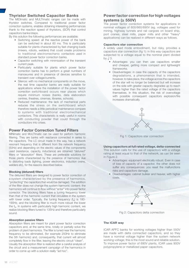
Power factor correction for high voltages systems (≥ 550V)The power factor correction systems for applications in nominal voltages of 600/660/690V (eg. voltages used for mining, highway tunnels and rail cargoes on board ship, port cranes, steel mills, paper mills and other "heavy" applications) can be realized in different ways as follows.
Capacitors star connectionA widely used mode embodiment, but risky, provides a capacitors star connection (fig 1): in this way capacitors are subjected to a voltage equal to the nominal plant divided by √ 3.
• Advantages: you can then use capacitors smaller and cheaper, getting more compact and lightweight frameworks.
• Disadvantages: in case the capacity of the capacitors degradations, a phenomenon that is intended, however, to take place, the voltage across the capacitors of the star will no longer be balanced but will increase on the side with greater capacity degrades up to reach values higher than the rated voltage of the capacitors themselves. In this situation, the risk of overvoltage with possible consequent capacitors explosion/fi re increases dramatically.
Fig 1: Capacitors star connection
Using capacitors at full rated voltage, delta-connectedThis solution calls for the use of capacitors with a voltage rating at least equal to that of the network, as can be seen in Figure 2.
• Advantages: equipment electrically robust. Even in case of loss of capacity of a capacitor, the other does not suff er any consequences: you reset the malfunctions risks and capacitors damage.
• Disadvantages: cabinet bulkier and heavier, with higher costs.
Fig 2: Capacitors delta connection
The ICAR way
ICAR APFC banks for working voltages higher than 550V are made with delta connected capacitors, and so they have a nominal voltage higher than the system network working voltage; this is the most sound and reliable solution.To improve power factor of 690V plants, ICAR uses 900V polypropylene or metallized paper capacitors.
11

The choice of power factor correction equipment must be made by evaluating the design data of the system or, better yet, your electricity bills. The choice of the power factor correction type must be carried out according to the following table, which shows on the ordinate the rate of harmonic distortion of the plant current (THDIR%) and in abscissa the ratio between the reactive power QC (in kvar) of the PFC bank and LV/MV transformer apparent power (kVA).
In light of these data, it identifies the box with proposed families, starting from the family that ensures the proper functioning with the best quality/price ratio.So you choose the automatic power factor corrector series. The fixed power factor correction must have the same electrical characteristics of the automatic.
The table was made starting from the following assumptions:• Network voltage 400V• Initial power factor of the plant 0.7 inductive• Power factor target 0.95 inductive• Non linear load with 5°-7° -11° -13° harmonics
current
The hypotheses used are general and valid in the most of cases. In particular situations (harmonics coming from other branch of network, presence of rank equal to or a multiple of 3 harmonics) previous considerations may be invalid.In these cases, the guarantee of a correct choice of the equipment occurs only as a result of a measurement campaign of harmonic analysis of the network and/or the appropriate calculations. ICAR disclaims any responsibility for incorrect choice of the product.
Automatic power factor correction systems 230vac rated voltageTHDI%> 27 HP10 FH20 FH20 FH20 FH20 FH20 FH20
20 <THDI%≤ 27 HP10 FH20 FH20 FH20 FH20 FH20 FH20
12 <THDI%≤ 20 HP10 FH20 FH20 HP10 HP10 FH20 FH20
THDI%≤ 12 HP10 HP10 HP10/FH20 HP10 HP10 FH20 FH20
QC/AT≤0,05 0,05<QC/AT≤0,1 0,1<QC/AT≤0,15 0,15<QC/AT≤0,2 0,2<QC/AT≤0,25 0,25<QC/AT≤0,3 QC/AT>0,3
QC/AT
Automatic power factor correction systems 400vac rated voltageTHDI%> 27 HP30 FH20/FH30 FH20/FH30 FH20/FH30 FH20/FH30 FH20/FH30 FH20/FH30
20 <THDI%≤ 27 HP30 FH20/FH30 FH20/FH30 HP30 HP30/FH20 FH20/FH30 FH20/FH30
12 <THDI%≤ 20 HP30 FH20/FH30 FH20/FH30 HP30 HP30 FH20/FH30 FH20/FH30
THDI%≤ 12 HP30 HP30 HP30/FH20 HP30 HP30 HP30/H20 FH20/FH30
QC/AT≤0,05 0,05<QC/AT≤0,1 0,1<QC/AT≤0,15 0,15<QC/AT≤0,2 0,2<QC/AT≤0,25 0,25<QC/AT≤0,3 QC/AT>0,3
QC/AT
Automatic power factor correction systems 440vac rated voltageTHDI%> 27 HP30 FH20 FH20 FH20 FH20 FH20 FH20
20 <THDI%≤ 27 HP30 FH20 FH20 HP30 HP30/FH20 FH20 FH20
12 <THDI%≤ 20 HP30 FH20 FH20 HP30 HP30 FH20 FH20
THDI%≤ 12 HP30 HP30 HP30/FH20 HP30 HP30 HP30/FH20 FH20
QC/AT≤0,05 0,05<QC/AT≤0,1 0,1<QC/AT≤0,15 0,15<QC/AT≤0,2 0,2<QC/AT≤0,25 0,25<QC/AT≤0,3 QC/AT>0,3
QC/AT
Automatic power factor correction systems 480vac rated voltageTHDI%> 27 HP30 FD00 FD00 FD00 FD00 FD00 FD00
20 <THDI%≤ 27 HP30 FD00 FD00 FD00 FD00 FD00 FD00
12 <THDI%≤ 20 HP30 FD00 FD00 FD00 FD00 FD00 FD00
THDI%≤ 12 HP30 HP30/FD00 FD00 HP30 HP30/FD00 FD00 FD00
QC/AT≤0,05 0,05<QC/AT≤0,1 0,1<QC/AT≤0,15 0,15<QC/AT≤0,2 0,2<QC/AT≤0,25 0,25<QC/AT≤0,3 QC/AT>0,3
QC/AT
Selection criteria dependingon the type of plant
12
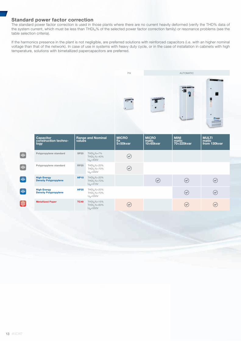
Standard power factor correction The standard power factor correction is used in those plants where there are no current heavily deformed (verify the THD% data of the system current, which must be less than THDIR% of the selected power factor correction family) or resonance problems (see the table selection criteria).
If the harmonics presence in the plant is not negligible, are preferred solutions with reinforced capacitors (i.e. with an higher nominal voltage than that of the network). In case of use in systems with heavy duty cycle, or in the case of installation in cabinets with high temperature, solutions with bimetallized papercapacitors are preferred.
FIX AUTOMATIC
Capacitorconstruction techno-logy
Range and Nominal values
MICROfi x5÷50kvar
MICROmatic10÷65kvar
MINImatic70÷225kvar
MULTImaticfrom 130kvar
Polypropylene standard SP20 THDIR%=7%THDIC%=40%UN=400V
Polypropylene standard RP20 THDIR%=20%THDIC%=70%UN=550V
High EnergyDensity Polypropylene
HP10 THDIR%=20%THDIC%=70%UN=415V
High EnergyDensity Polypropylene
HP30 THDIR%=20%THDIC%=70%UN=550V
Metallized Paper TC40 THDIR%=15%THDIC%=60%UN=550V
13

Power factor correction with blocking reactorsThe power factor correction with blocking reactors (this solution is called in different ways in the technical literature such as “blocking filters", or "detuned filters", or "detuned power factor correctors", etc.) is a solution used when a current flows in the electric system with a high harmonic content (THD) and / or with the resonance risk with the MV/LV transformer. In these cases, the installation of a "normal" power factor corrector, devoid of blocking reactors, can cause the rapid degradation of the capacitors and cause dangerous electrical and mechanical stresses in the components of power plant (cables, busbars, switches, transformers).Chokes protect the capacitors by harmonics and at the same time exclude the resonances risk; leave without sacrificing the harmonic content of the current system *.
* If you want to reduce the system harmonic content, you must install active or passive filters. Consult us.
This type of power factor correction is therefore to be preferred for systems with important non-linear loads (lighting not luminescent, power electronics, VSD, soft starters, induction furnaces, welding machines...).
ICAR offers two types of solutions with power factor correction with blocking reactors: one with 180Hz blocking frequency (detuned to 3.6 times the line frequency) and another one with 135Hz (2.7). It’s correct noting that the lower the tuning frequency is the more robust is the cabinet, because the reactor should have a larger iron core.ICAR power factor correction with blocking reactor, solutions are made with capacitors and inductors produced in the group; also are used only capacitors with rated voltage higher than that of the network, to ensure strength and durability counteracting the Ferranti effect (permanent overvoltage on the capacitor due to the blocking inductance).
AUTOMATIC
Capacitorconstruction technology
Range andNominal values
MULTImaticfrom 75kvar
High EnergyDensity Polypropylene
FH20 THDIR%<60%THDV%<6%UN=550VfN=216Hz
High EnergyDensity Polypropylene
FH30 THDIR%>60%THDV%<6%UN=550VfN=162Hz
Metallized Paper FD40 THDIR%<60%THDV%<6%UN=660VfN=216Hz
14
GENERALITIES:• Zink-passivated metallic enclosure painted with epossidic
dust paint, colour RAL 7035.• Auxiliary transformer to separate power and auxiliary circuit
parts (110V).• Load-break switch with door interlock designed at 1,495* In
as per IEC 60831-1 art.34.• Contactors with damping resistors to limit capacitors inrush
current.• N07V-K self-extinguish cable according to IEC 50267-2--1
standards.• Microprocessor Power Factor Correction relay• Single phase self-healing metallized polypropylene capacitor
with UN=415V rated voltage.
All components inside this products are compliant with EU Safety.
CODE IP3X POWERUe=230V
60Hz (kvar)
STEP1kvar
Ue=230V60Hz
STEP2kvar
STEP3kvar
STEP4kvar
STEP5kvar
STEP6kvar
RegulatorType
L.B.SWITCH
(A)
ICC(kA)
WeightKg
Dim.WxHxD(mm) IP3X
MIC
RO
mat
ic
IC0ABB150060652 5 0,75 1,5 3,0 RPC 5LGA 63 50 12 51IC0ABB175060652 7,5 1,5 3,0 3,0 RPC 5LGA 63 50 13 51IC0ABB180060652 8 0,75 1,5 3,0 3,0 RPC 5LGA 80 50 16 52IC0ABB210060652 10 1,5 3,0 6,0 RPC 5LGA 80 50 14 51IC0ABB211060652 11 0,75 1,5 3,0 6,0 RPC 5LGA 80 50 17 52IC0ABB213060652 13 1,5 3,0 3,0 6,0 RPC 5LGA 100 50 18 52IC0ABB214060652 14 0,75 1,5 3,0 3,0 6,0 RPC 5LGA 100 50 22 52IC0ABB217060652 17 1,5 3,0 6,0 6,0 RPC 5LGA 100 50 23 52IC0ABB220060652 20 1,5 3,0 6,0 9,0 RPC 5LGA 125 50 25 52IC0ABB223060652 23 1,5 3,0 6,0 12,0 RPC 5LGA 125 50 27 52IC0ABB227060652 27 3,0 6,0 6,0 12,0 RPC 5LGA 160 50 29 52
CODE IP3X POWERUe=230V
60Hz (kvar)
STEP1kvar
STEP2kvar
STEP3kvar
STEP4kvar
STEP5kvar
STEP6kvar
RegulatorType
L.B.SWITCH
(A)
ICC(kA)
WeightKg
Dim.IP3X
MIN
Imat
ic
IF0ABB230060652 30 3 6 9 12 RPC 5LGA 250 9 41 55IF0ABB242060652 42 3 6 9 12 12 RPC 5LGA 250 9 47 56IF0ABB251060652 51 3 6 9 12 21 RPC 5LGA 400 9 51 56IF0ABB262060652 62 6 12 18 24 RPC 5LGA 400 9 54 56IF0ABB272060652 72 6 12 24 30 RPC 5LGA 400 9 60 57IF0ABB278060652 78 6 12 24 36 RPC 5LGA 500 9 65 57IF0ABB290060652 90 6 12 24 48 RPC 5LGA 500 9 69 57IF0ABB310260652 102 12 24 24 42 RPC 5LGA 400 9 74 58
CODE IP4X POWERUe=230V
60Hz (kvar)
STEP1kvar
STEP2kvar
STEP3kvar
STEP4kvar
STEP5kvar
STEP6kvar
RegulatorType
L.B.SWITCH
(A)
ICC(kA)
WeightKg
Dim.IP4X
MU
LTIm
atic
IN0ABB312060700 120 12 12 24 24 24 24 RPC 8BGA 800 50 300 72IN0ABB315060700 150 15 15 30 30 30 30 RPC 8BGA 1250 50 340 72IN0ABB318060700 180 18 18 36 36 36 36 RPC 8BGA 1250 50 360 72IN0ABB321060700 210 21 21 42 42 42 42 RPC 8BGA 1250 50 400 74IN0ABB324060700 240 24 24 48 48 48 48 RPC 8BGA 2x800 50 560 92IN0ABB327060700 270 27 27 54 54 54 54 RPC 8BGA 2x800 50 640 92IN0ABB330060700 300 30 30 60 60 60 60 RPC 8BGA 2x1250 50 660 92IN0ABB333060700 330 33 33 66 66 66 66 RPC 8BGA 2x1250 50 700 92IN0ABB336060700 360 36 36 72 72 72 72 RPC 8BGA 2x1250 50 720 92IN0ABB339060700 390 39 39 78 78 78 78 RPC 8BGA 2x1250 50 760 94IN0ABB342060700 420 42 42 84 84 84 84 RPC 8BGA 2x1250 50 800 94
TECHNICAL CHARACTERISTICS:Rated operational voltage Ue=230V
Rated frequency 60Hz
Max current overload In (capacitors) 1,3xIn (continous)
Max voltage overload Vn (capacitors) 3 x UN (for 1 min.)
Max current overload In (bank) 1.3xIn
Max voltage overload Vn (bank) 1.1xUe
Insulating voltage (bank) 690V
Temperature range (capacitors) -25/+55°C
Temperature range (bank) -5/+40°C
Discharge device on each bank
Use indoor
Service continous
Capacitors connection delta
Operation devices capacitors contactors (AC6b)
Total losses ~ 2W/kvar
Inner surface fi nish zinc passivation
Standards (capacitors) IEC 60831-1/2
Standards (bank) IEC 61439-1/2, IEC 61921
Ue UN UMAX1 f THDIR% THDIC%2
230V 415V 455V 60 Hz ≤20% ≤70%
MICROmatic
MINImatic
MULTImatic
AUTOMATIC POWER FACTOR CORRECTION SYSTEMS
HP10
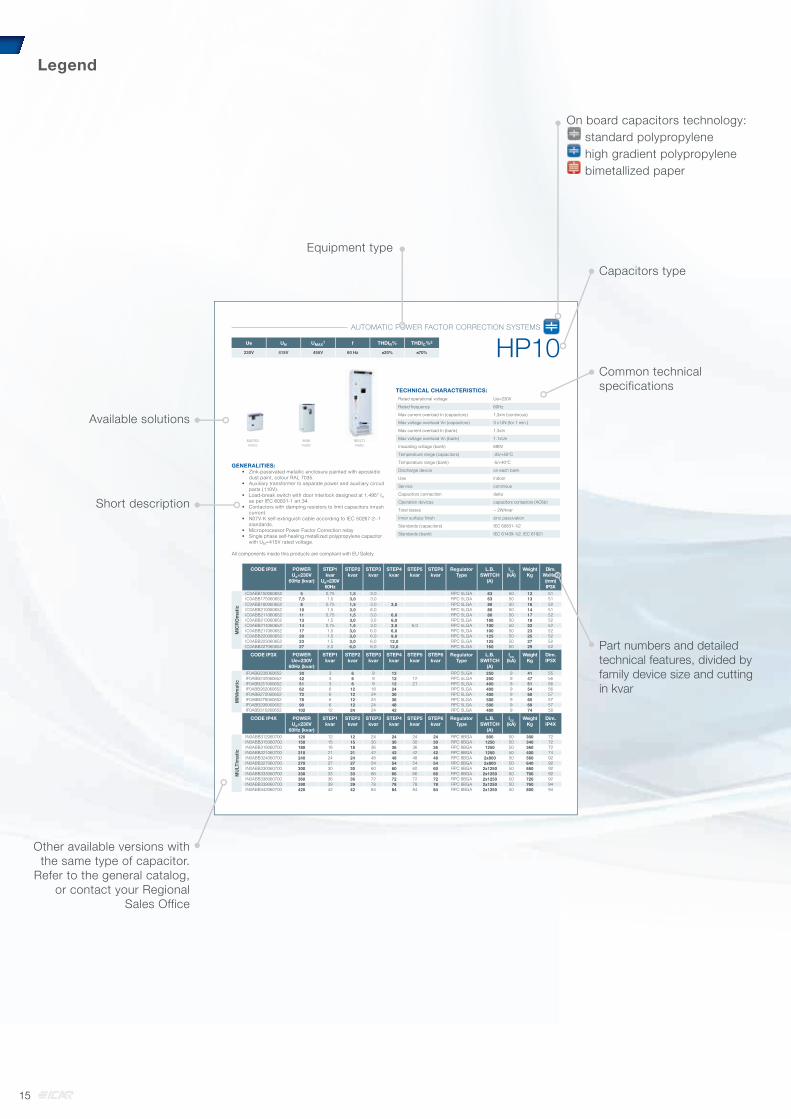
Legend
Capacitors type
On board capacitors technology:On board capacitors technology: standard polypropylene high gradient polypropylene bimetallized paper
Equipment type
Common technicalspecifications
Part numbers and detailed technical features, divided by family device size and cutting in kvar
Available solutions
Short description
Other available versions with the same type of capacitor.
Refer to the general catalog, or contact your Regional
Sales Office
15

Power factor correction solutions withstandard or high gradient metallizedpolypropylene capacitors
SP20 Fix Power Factor Correction Systems with standard polypropylene film and 400V nominal voltage capacitors
RP20 Fix Power Factor Correction Systems with standard polypropylene film and 460V nominal voltage capacitors
HP10 Automatic Power Factor Correction Systems with high energy density polypropylene film and 415V nominal voltage capacitors
HP30 Automatic Power Factor Correction Systems with high energy density polypropylene film and 550V nominal voltage capacitors
FH20 Automatic and fix detuned Power Factor Correction Systems with 180Hz detuned reactors and high energy density polypropylene film and 550V nominal voltage capacitors .
FH30 Automatic detuned Power Factor Correction Systems with 135Hz detuned reactors and high energy density polypropylene film and 550V nominal voltage capacitors.
NB: see page 10 for standard and optional features.
CHAPTER 3
16

Range Part number Model Rated VoltageUN (V)
MAX VoltageUMAX (V)
Power(kvar)
Capaci-tance(μF)
DIM(mm)
Weight(kg)
Pcs/box
SP20 CRMT166163400C0 CRM25-11C-1.66-400 400 440 1,66 33,3 55x128 0,4 36
CRMT208163400B0 CRM25-11B-2.08-400 400 440 2,08 41,3 55x128 0,4 36
CRMT333163400A0 CRM25-11A-3.33-400 400 440 3,33 66,6 60x138 0,5 36
CRMT416163400A0 CRM25-11A-4.16-400 400 440 4,16 82,7 60x138 0,5 36
RP10 CRMM166163400B0 CRM25-11B-1.66-460 460 500 1,66 25 55x128 0,4 36
CRMM333163400B0 CRM25-11B-3.33-460 460 500 3,33 50 60x138 0,5 36
CRMM372163400B0 CRM25-11B-3.72-460 460 500 3,72 56 60x138 0,5 36
RP20 CRMR166163300A0 CRM25-11A-1.66-550 550 600 1,66 17,5 45x128 0,3 50
CRMR333163400A0 CRM25-11A-3.33-550 550 600 3,33 35 60x138 0,5 36
TECHNICAL CHARACTERISTICS:Rated operational voltage Ue=400-460-550V
Rated frequency 50Hz
Max current overload In 1,3 In
Max voltage overload Vn 1.1x
Insulating voltage 3/15kV - Ue≤660Vac
Temperature range -25/+55°C
Capacitance tolerance -5÷+10%
Terminal voltage test 2.15xUN 10 sec.
Service continous
Capacitors connection polypropylene
Standards IEC 60831-1/2
GENERALITIES:• Metallic case with protection degree IP00 (other on request)• Internal overpressure protection system• Resin or oil impregnation
All parts inside these products are compliant with Safety Regulations.
Capacitors at frequency 50Hz used in PFC systems at 60Hz take account of the increase in frequency.
CYLINDRICAL SINGLE PHASE POWER CAPACITORS
CRM25
17

Range Part number Model Rated VoltageUN (V)
MAX VoltageUMAX (V)
Power(kvar)
Capaci-tance(μF)
DIM(mm)
Weight(kg)
Pcs/box
HP10 CRMK69006320SB0 CRM-25-11A-0.69-415 415 456 0,69 12,2 55x78 0,25 36
CRMK13816320SB0 CRM-25-11A-1.38-415 415 456 1,38 25,4 55x78 0,25 36
CRMK275163400A0 CRM25-11A-2.75-415 415 456 2,75 50,8 60x138 0,5 36
CRMK550163400A0 CRM25-11A-5.50-415 415 456 5,5 101,7 60x138 0,5 36
HP30FH20
CRMR13816320SB0 CRM25-11A-1.38-550 550 600 1,38 14,5 55x78 0,25 36
CRMR275163400A0 CRM25-11A-2.75-550 550 600 2,75 28,9 60x138 0,5 36
CRMR550163400A0 CRM25-11A-5.50-550 550 600 5,5 57,9 60x138 0,5 36
TECHNICAL CHARACTERISTICS:Rated operational voltage Ue=415-550V
Rated frequency 50Hz
Max current overload In 1,3 In (continous)2 In (x 380s)3 In (x150s)4 In (x70s)5 In (x45s)
Max voltage overload Vn 1.1x
Insulating voltage 3/15kV - Ue≤660Vac
Temperature range -25/+55°C
Capacitance tolerance -5÷+10%
Terminal voltage test 2.15xUN 10 sec.
Service continous
Capacitors connection high gradient metallized polypropylene
Standards IEC 60831-1/2
GENERALITIES:• Metallic case with protection degree IP00• Internal overpressure protection system• Oil impregnation vacuum packed
All parts inside these products are compliant with Safety Regulations.
Capacitors at frequency 50Hz used in PFC systems at 60Hz take account of the increase in frequency.
CYLINDRICAL SINGLE PHASE POWER CAPACITORS
CRM25
18

CODE IPX3 PowerUe=240V
(kvar)
Seleziona-tore L.B.
Switch (A)
ICC3 Weight
KgDIMIP3X
DIMIP554
SP20
IB1AYY120060003 2 40 80 8 41 43
IB1AYY140060003 4 40 80 9 41 43
IB1AYY160060003 6 40 80 10 41 43
IB1AYY180060003 8 63 80 12 41 43
IB1AYY211060003 11 63 80 13 41 43
IB1AYY213060003 13 80 80 15 41 43
IB1AYY217060003 17 125 80 18 42 43
IB1AYY221060003 21 125 80 20 42 43
IB1AYY226060003 26 200 80 22 42 43
CODE IPX3 PowerUe=440V
(kvar)
Seleziona-tore L.B.
Switch (A)
ICC3 Weight
KgDIMIP3X
DIMIP554
RP2
0
IB1NEE140060003 4 40 80 8 41 43
IB1NEE170060003 7 40 80 9 41 43
IB1NEE211060003 11 40 80 10 41 43
IB1NEE215060003 15 40 80 12 41 43
IB1NEE219060003 19 40 80 13 41 43
IB1NEE223060003 23 63 80 15 41 43
IB1NEE231060003 31 125 80 18 42 43
IB1NEE238060003 38 125 80 20 42 43
IB1NEE246060003 46 125 80 22 42 43
CODE IPX3 PowerUe=400V
(kvar)
Seleziona-tore L.B.
Switch (A)
ICC3 Weight
KgDIMIP3X
DIMIP554
RP2
0
IB1NFF130060003 3 40 80 8 41 43
IB1NFF160060003 6 40 80 9 41 43
IB1NFF190060003 9 40 80 10 41 43
IB1NFF212060003 12 40 80 12 41 43
IB1NFF216060003 16 40 80 13 41 43
IB1NFF219060003 19 63 80 15 41 43
IB1NFF226060003 26 125 80 18 42 43
IB1NFF231060003 31 125 80 20 42 43
IB1NFF238060003 38 125 80 22 42 43
MICROfix: GENERALITIES• Metallic enclosure internally and externally
painted with epossidic dust paint, color RAL 7035.
• Load-break switch with door interlock, designed at 1,495 In according to IEC 60831-1 art.34.
• N07V-K self-extinguish cable according to IEC 50267-2-1 standards.
• IP 3X degree of protection• Single phase self-healing metallized
polypropylene capacitors with UN=400-550V rated voltage, capacitors equipped with discharge resistors
• Signal lamps power on
All components inside this products are compliant with EU Safety Regulations.
TECHNICAL CHARACTERISTICS:Rated operational voltage Ue=240V-400V-440V
Rated frequency 60Hz
Max current overload In 1.3xIn
Max voltage overload Vn 1,1xUe
Insulating voltage(SUPERriphaso, Riphaso)
3/15kV - Ue≤660Vac
Insulating voltage (MICROfi x) 690V
Temperature range (capacitor bank) -5/+40°C
Temperature range (capacitors) -25/+55°C
Discharge device on each bank
Use indoor
Service continous
Capacitors connection delta
Total losses ~ 2W/kvar
Inner surface fi nish (MICROfi x) zinc passivation
Applicable standards IEC 61439-1/2, IEC 61921
Capacitors standards IEC 60831-1/2
Ue UN UMAX1 f THDIR% THDIC%2
240V-400V-440V 400-550V 440-600V 60 Hz ≤7% ≤40%
MICROfi xMICROfi x
FIX PFC SYSTEMS
RP-SP
19

GENERALITIES:• Zink-passivated metallic enclosure painted with epossidic
dust paint, colour RAL 7035.• Auxiliary transformer to separate power and auxiliary circuit
parts (110V).• Load-break switch with door interlock designed at 1,495* In
as per IEC 60831-1 art.34.• Contactors with damping resistors to limit capacitors inrush
current.• N07V-K self-extinguish cable according to IEC 50267-2--1
standards.• Microprocessor Power Factor Correction relay• Single phase self-healing metallized polypropylene capacitor
with UN=415V rated voltage.
All components inside this products are compliant with EU Safety.
CODE IP3X POWERUe=230V
60Hz (kvar)
STEP1kvar
Ue=230V60Hz
STEP2kvar
STEP3kvar
STEP4kvar
STEP5kvar
STEP6kvar
RegulatorType
L.B.SWITCH
(A)
ICC(kA)
WeightKg
Dim.WxHxD(mm) IP3X
MIC
RO
mat
ic
IC0ABB150060652 5 0,75 1,5 3,0 RPC 5LGA 63 50 12 51IC0ABB175060652 7,5 1,5 3,0 3,0 RPC 5LGA 63 50 13 51IC0ABB180060652 8 0,75 1,5 3,0 3,0 RPC 5LGA 80 50 16 52IC0ABB210060652 10 1,5 3,0 6,0 RPC 5LGA 80 50 14 51IC0ABB211060652 11 0,75 1,5 3,0 6,0 RPC 5LGA 80 50 17 52IC0ABB213060652 13 1,5 3,0 3,0 6,0 RPC 5LGA 100 50 18 52IC0ABB214060652 14 0,75 1,5 3,0 3,0 6,0 RPC 5LGA 100 50 22 52IC0ABB217060652 17 1,5 3,0 6,0 6,0 RPC 5LGA 100 50 23 52IC0ABB220060652 20 1,5 3,0 6,0 9,0 RPC 5LGA 125 50 25 52IC0ABB223060652 23 1,5 3,0 6,0 12,0 RPC 5LGA 125 50 27 52IC0ABB227060652 27 3,0 6,0 6,0 12,0 RPC 5LGA 160 50 29 52
CODE IP3X POWERUe=230V
60Hz (kvar)
STEP1kvar
STEP2kvar
STEP3kvar
STEP4kvar
STEP5kvar
STEP6kvar
RegulatorType
L.B.SWITCH
(A)
ICC(kA)
WeightKg
Dim.IP3X
MIN
Imat
ic
IF0ABB230060652 30 3 6 9 12 RPC 5LGA 250 9 41 55IF0ABB242060652 42 3 6 9 12 12 RPC 5LGA 250 9 47 56IF0ABB251060652 51 3 6 9 12 21 RPC 5LGA 400 9 51 56IF0ABB262060652 62 6 12 18 24 RPC 5LGA 400 9 54 56IF0ABB272060652 72 6 12 24 30 RPC 5LGA 400 9 60 57IF0ABB278060652 78 6 12 24 36 RPC 5LGA 500 9 65 57IF0ABB290060652 90 6 12 24 48 RPC 5LGA 500 9 69 57IF0ABB310260652 102 12 24 24 42 RPC 5LGA 400 9 74 58
CODE IP4X POWERUe=230V
60Hz (kvar)
STEP1kvar
STEP2kvar
STEP3kvar
STEP4kvar
STEP5kvar
STEP6kvar
RegulatorType
L.B.SWITCH
(A)
ICC(kA)
WeightKg
Dim.IP4X
MU
LTIm
atic
IN0ABB312060700 120 12 12 24 24 24 24 RPC 8BGA 800 50 300 72IN0ABB315060700 150 15 15 30 30 30 30 RPC 8BGA 1250 50 340 72IN0ABB318060700 180 18 18 36 36 36 36 RPC 8BGA 1250 50 360 72IN0ABB321060700 210 21 21 42 42 42 42 RPC 8BGA 1250 50 400 74IN0ABB324060700 240 24 24 48 48 48 48 RPC 8BGA 2x800 50 560 92IN0ABB327060700 270 27 27 54 54 54 54 RPC 8BGA 2x800 50 640 92IN0ABB330060700 300 30 30 60 60 60 60 RPC 8BGA 2x1250 50 660 92IN0ABB333060700 330 33 33 66 66 66 66 RPC 8BGA 2x1250 50 700 92IN0ABB336060700 360 36 36 72 72 72 72 RPC 8BGA 2x1250 50 720 92IN0ABB339060700 390 39 39 78 78 78 78 RPC 8BGA 2x1250 50 760 94IN0ABB342060700 420 42 42 84 84 84 84 RPC 8BGA 2x1250 50 800 94
TECHNICAL CHARACTERISTICS:Rated operational voltage Ue=230V
Rated frequency 60Hz
Max current overload In (capacitors) 1,3xIn (continous)
Max voltage overload Vn (capacitors) 3 x UN (for 1 min.)
Max current overload In (bank) 1.3xIn
Max voltage overload Vn (bank) 1.1xUe
Insulating voltage (bank) 690V
Temperature range (capacitors) -25/+55°C
Temperature range (bank) -5/+40°C
Discharge device on each bank
Use indoor
Service continous
Capacitors connection delta
Operation devices capacitors contactors (AC6b)
Total losses ~ 2W/kvar
Inner surface fi nish zinc passivation
Standards (capacitors) IEC 60831-1/2
Standards (bank) IEC 61439-1/2, IEC 61921
Ue UN UMAX1 f THDIR% THDIC%2
230V 415V 455V 60 Hz ≤20% ≤70%
MICROmatic
MINImatic
MULTImatic
AUTOMATIC POWER FACTOR CORRECTION SYSTEMS
HP10
20

GENERALITIES:• Zink-passivated metallic enclosure painted with epossidic
dust paint, colour RAL 7035.• Auxiliary transformer to separate power and auxiliary circuit
parts (110V).• Load-break switch with door interlock designed at 1,495* In
as per IEC 60831-1 art.34.• Contactors with damping resistors to limit capacitors’ inrush
current.• N07V-K self-extinguish cable according to IEC 50267-2-1
standards.• Microprocessor Power Factor Correction relay• Single phase self-healing metallized polypropylene
capacitor with UN=550V rated voltage.
All components inside this products are compliant with EU Safety Regulations.
CODE IP3X POWERUe=400V
60Hz (kvar)
STEP1kvar
STEP2kvar
STEP3kvar
STEP4kvar
STEP5kvar
STEP6kvar
RegulatorType
L.B.SWITCH
(A)
ICC(kA)
WeightKg
Dim.IP3X
MIC
RO
mat
ic
IC0TFF190060652 9 1,3 2,5 5 RPC 5LGA 63 9 12 55IC0TFF213060652 13 2,5 5 5 RPC 5LGA 63 9 13 56IC0TFF214060652 14 1,3 2,5 5 5 RPC 5LGA 80 9 16 56IC0TFF218060652 18 2,5 5 10 RPC 5LGA 80 9 14 56IC0TFF219060652 19 1,3 2,5 5 10 RPC 5LGA 80 9 17 57IC0TFF223060652 23 2,5 5 5 10 RPC 5LGA 100 9 18 57IC0TFF224060652 24 1,3 2,5 5 5 10 RPC 5LGA 100 9 22 57IC0TFF228060652 28 2,5 5 10 10 RPC 5LGA 100 9 23 58IC0TFF233060652 33 2,5 5 10 15 RPC 5LGA 125 9 25 58IC0TFF238060652 38 2,5 5 10 20 RPC 5LGA 125 10 27 58IC0TFF245060652 45 5 10 10 20 RPC 5LGA 160 11 29 58
MIN
Imat
ic
IF0TFF250060652 50 5 10 15 20 RPC 5LGA 125 9 41 55IC0TFF270060652 70 5 10 15 20 20 RPC 5LGA 125 9 47 56IC0TFF285060652 85 5 10 15 20 35 RPC 5LGA 250 9 51 56IC0TFF310060652 100 10 20 30 40 RPC 5LGA 250 9 54 56IC0TFF312060652 120 10 20 40 50 RPC 5LGA 250 9 60 57IC0TFF313560652 135 10 20 40 65 RPC 5LGA 400 9 65 57IC0TFF315060652 150 10 20 40 80 RPC 5LGA 400 9 69 57IC0TFF317060652 170 20 40 40 70 RPC 5LGA 400 9 78 58IC0TFF320060652 200 20 40 60 80 RPC 5LGA 400 9 88 58
CODE IP4X POWERUe=400V
60Hz (kvar)
STEP1kvar
STEP2kvar
STEP3kvar
STEP4kvar
STEP5kvar
STEP6kvar
RegulatorType
L.B.SWITCH
(A)
ICC(kA)
WeightKg
Dim.IP4X
MU
LTIm
atic
IN2DFF315060700 150 15 15 30 30 30 30 RPC 8BGA 400 25 178 72IN2DFF320060700 200 20 20 40 40 40 40 RPC 8BGA 400 25 190 72IN2DFF325060700 250 25 25 50 50 50 50 RPC 8BGA 630 25 212 72IN2DFF330060700 300 30 30 60 60 60 60 RPC 8BGA 800 50 252 72IN2DFF335060700 350 35 35 70 70 70 70 RPC 8BGA 800 50 274 74IN2DFF340060700 400 40 40 80 80 80 80 RPC 8BGA 1250 50 300 74IN2DFF345060700 450 45 45 90 90 90 90 RPC 8BGA 1250 50 320 70IN2DFF350060700 500 50 50 100 100 100 100 RPC 8BGA 1250 50 340 70IN2DFF355060700 550 55 55 110 110 110 110 RPC 8BGA 2x630 25 360 92IN2DFF360060700 600 60 60 120 120 120 120 RPC 8BGA 2x800 50 400 92IN2DFF365060700 650 65 65 130 130 130 130 RPC 8BGA 2x800 50 440 94IN2DFF370060700 700 70 70 140 140 140 140 RPC 8BGA 2x800 50 480 94IN2DFF375060700 750 75 75 150 150 150 150 RPC 8BGA 2x800 50 620 94IN2DFF380060700 800 80 80 160 160 160 160 RPC 8BGA 2x1250 50 640 94IN2DFF385060700 850 85 85 170 170 170 170 RPC 8BGA 2x1250 50 660 90IN2DFF390060700 900 90 90 180 180 180 180 RPC 8BGA 2x1250 50 680 90IN2DFF395060700 950 95 95 190 190 190 190 RPC 8BGA 2x1250 50 705 90IN2DFF410060700 1000 100 100 200 200 200 200 RPC 8BGA 2x1250 50 730 90IN2DFF410560700 1050 105 105 210 210 210 210 RPC 8BGA 2x1250 50 755 91IN2DFF411060700 1100 110 110 220 220 220 220 RPC 8BGA 2x1250 50 780 91
TECHNICAL CHARACTERISTICS:Rated operational voltage Ue=400V
Rated frequency 60Hz
Max current overload In (capacitors) 1,3xIn (continous)
Max voltage overload Vn (capacitors) 3xUN (for 1 min.)
Max current overload In (bank) 1.3xIn
Max voltage overload Vn (bank) 1.1xUe
Insulating voltage (bank) 690V
Temperature range (capacitors) -25/+55°C
Temperature range (bank) -5/+40°C
Discharge device on each bank
Use indoor
Service continous
Capacitors connection delta
Operation devices capacitors
Total losses ~ 2W/kvar
Inner surface fi nish zinc passivation
Standards (capacitors) IEC 60831-1/2
Standards (bank) IEC 61439-1/2, IEC 61921
Ue UN UMAX1 f THDIR% THDC%
400V 550V 600V 60 Hz 20% 70%
MICROmatic
MINImatic
MULTImatic
DETUNED AUTOMATIC POWER FACTOR CORRECTION SYSTEMS
HP30
21

GENERALITIES:• Zink-passivated metallic enclosure painted with epossidic
dust paint, colour RAL 7035.• Auxiliary transformer to separate power and auxiliary circuit
parts (110V).• Load-break switch with door interlock designed at 1,495* In
as per IEC 60831-1 art.34.• Contactors with damping resistors to limit capacitors’ inrush
current.• N07V-K self-extinguish cable according to IEC 50267-2-1
standards.• Microprocessor Power Factor Correction relay• Single phase self-healing metallized polypropylene
capacitor with UN=550V rated voltage.
All components inside this products are compliant with EU Safety Regulations.
CODE IP3X POWERUe=440V
60Hz (kvar)
STEP1kvar
STEP2kvar
STEP3kvar
STEP4kvar
STEP5kvar
STEP6kvar
RegulatorType
L.B.SWITCH
(A)
ICC(kA)
WeightKg
Dim.IP3X
MIC
RO
mat
ic
IC0TEE211060652 11 1,5 3 6 RPC 5LGA 63 9 12 51IC0TEE215060652 15 3 6 6 RPC 5LGA 63 9 13 51IC0TEE217060652 17 1,5 3 6 6 RPC 5LGA 80 9 16 52IC0TEE221060652 21 3 6 12 RPC 5LGA 80 9 14 51IC0TEE223060652 23 1,5 3 6 12 RPC 5LGA 80 9 17 52IC0TEE227060652 27 3 6 6 12 RPC 5LGA 100 9 18 52IC0TEE229060652 29 1,5 3 6 6 12 RPC 5LGA 100 9 22 52IC0TEE233060652 33 3 6 12 12 RPC 5LGA 100 9 23 52IC0TEE239060652 39 3 6 12 18 RPC 5LGA 125 9 25 52IC0TEE245060652 45 3 6 12 24 RPC 5LGA 125 10 27 52IC0TEE254060652 54 6 12 12 24 RPC 5LGA 160 11 29 52
MIN
Imat
ic
IF0TEE265060652 65 6,5 13 19,5 26 RPC 5LGA 125 9 41 55IF0TEE291060652 91 6,5 13 19,5 26 26 RPC 5LGA 125 9 47 56IF0TEE311160652 111 6,5 13 19,5 26 46 RPC 5LGA 250 9 51 56IF0TEE313060652 130 13 26 39 52 RPC 5LGA 250 9 54 56IF0TEE315660652 156 13 26 52 65 RPC 5LGA 250 9 60 57IF0TEE317660652 176 13 26 52 85 RPC 5LGA 400 9 65 57IF0TEE319560652 195 13 26 52 104 RPC 5LGA 400 9 69 57IF0TEE321160652 221 26 52 52 91 RPC 5LGA 500 9 78 58
CODE IP4X POWERUe=440V
60Hz (kvar)
STEP1kvar
STEP2kvar
STEP3kvar
STEP4kvar
STEP5kvar
STEP6kvar
RegulatorType
L.B.SWITCH
(A)
ICC(kA)
WeightKg
Dim.IP4X
MU
LTIm
atic
IN2DEE312560700 125 13 13 25 25 25 25 RPC 8BGA 250 17 178 72IN2DEE318860700 188 19 19 38 38 38 38 RPC 8BGA 400 25 190 72IN2DEE325060700 250 25 25 50 50 50 50 RPC 8BGA 630 25 212 72IN2DEE331360700 313 31 31 62 62 62 62 RPC 8BGA 630 25 252 72IN2DEE337560700 375 38 38 75 75 75 75 RPC 8BGA 800 50 274 72IN2DEE343860700 438 44 44 88 88 88 88 RPC 8BGA 1250 50 300 74IN2DEE350060700 500 50 50 100 100 100 100 RPC 8BGA 1250 50 320 74IN2DEE356360700 563 56 56 112 112 112 112 RPC 8BGA 1250 50 340 70IN2DEE362560700 625 63 63 125 125 125 125 RPC 8BGA 1250 50 360 70IN2DEE368860700 688 69 69 138 138 138 138 RPC 8BGA 2x630 25 400 92IN2DEE375060700 750 75 75 150 150 150 150 RPC 8BGA 2x800 50 440 92IN2DEE381360700 813 81 81 162 162 162 162 RPC 8BGA 2x800 50 480 94
TECHNICAL CHARACTERISTICS:Rated operational voltage Ue=440V
Rated frequency 60Hz
Max current overload In (capacitors) 1,3xIn (continous)
Max voltage overload Vn (capacitors) 3xUN (for 1 min.)
Max current overload In (bank) 1.3xIn
Max voltage overload Vn (bank) 1.1xUe
Insulating voltage (bank) 690V
Temperature range (capacitors) -25/+55°C
Temperature range (bank) -5/+40°C
Discharge device on each bank
Use indoor
Service continous
Capacitors connection delta
Operation devices capacitors
Total losses ~ 2W/kvar
Inner surface fi nish zinc passivation
Standards (capacitors) IEC 60831-1/2
Standards (bank) IEC 61439-1/2, IEC 61921
Ue UN UMAX1 f THDIR% THDC%
440V 550V 600V 60 Hz 20% 70%
MICROmatic
MINImatic
MULTImatic
DETUNED AUTOMATIC POWER FACTOR CORRECTION SYSTEMS
HP30
22
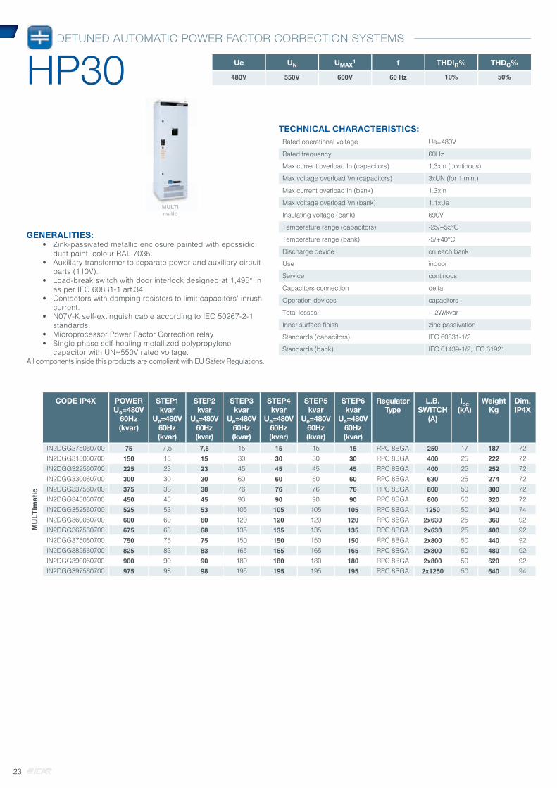
GENERALITIES:• Zink-passivated metallic enclosure painted with epossidic
dust paint, colour RAL 7035.• Auxiliary transformer to separate power and auxiliary circuit
parts (110V).• Load-break switch with door interlock designed at 1,495* In
as per IEC 60831-1 art.34.• Contactors with damping resistors to limit capacitors’ inrush
current.• N07V-K self-extinguish cable according to IEC 50267-2-1
standards.• Microprocessor Power Factor Correction relay• Single phase self-healing metallized polypropylene
capacitor with UN=550V rated voltage.All components inside this products are compliant with EU Safety Regulations.
CODE IP4X POWERUe=480V
60Hz(kvar)
STEP1kvar
Ue=480V 60Hz (kvar)
STEP2kvar
Ue=480V 60Hz (kvar)
STEP3kvar
Ue=480V 60Hz (kvar)
STEP4kvar
Ue=480V 60Hz (kvar)
STEP5kvar
Ue=480V 60Hz (kvar)
STEP6kvar
Ue=480V 60Hz (kvar)
RegulatorType
L.B.SWITCH
(A)
ICC(kA)
WeightKg
Dim.IP4X
MU
LTIm
atic
IN2DGG275060700 75 7,5 7,5 15 15 15 15 RPC 8BGA 250 17 187 72IN2DGG315060700 150 15 15 30 30 30 30 RPC 8BGA 400 25 222 72IN2DGG322560700 225 23 23 45 45 45 45 RPC 8BGA 400 25 252 72IN2DGG330060700 300 30 30 60 60 60 60 RPC 8BGA 630 25 274 72IN2DGG337560700 375 38 38 76 76 76 76 RPC 8BGA 800 50 300 72IN2DGG345060700 450 45 45 90 90 90 90 RPC 8BGA 800 50 320 72IN2DGG352560700 525 53 53 105 105 105 105 RPC 8BGA 1250 50 340 74IN2DGG360060700 600 60 60 120 120 120 120 RPC 8BGA 2x630 25 360 92IN2DGG367560700 675 68 68 135 135 135 135 RPC 8BGA 2x630 25 400 92IN2DGG375060700 750 75 75 150 150 150 150 RPC 8BGA 2x800 50 440 92IN2DGG382560700 825 83 83 165 165 165 165 RPC 8BGA 2x800 50 480 92IN2DGG390060700 900 90 90 180 180 180 180 RPC 8BGA 2x800 50 620 92IN2DGG397560700 975 98 98 195 195 195 195 RPC 8BGA 2x1250 50 640 94
TECHNICAL CHARACTERISTICS:Rated operational voltage Ue=480V
Rated frequency 60Hz
Max current overload In (capacitors) 1,3xIn (continous)
Max voltage overload Vn (capacitors) 3xUN (for 1 min.)
Max current overload In (bank) 1.3xIn
Max voltage overload Vn (bank) 1.1xUe
Insulating voltage (bank) 690V
Temperature range (capacitors) -25/+55°C
Temperature range (bank) -5/+40°C
Discharge device on each bank
Use indoor
Service continous
Capacitors connection delta
Operation devices capacitors
Total losses ~ 2W/kvar
Inner surface fi nish zinc passivation
Standards (capacitors) IEC 60831-1/2
Standards (bank) IEC 61439-1/2, IEC 61921
Ue UN UMAX1 f THDIR% THDC%
480V 550V 600V 60 Hz 10% 50%
MULTImatic
DETUNED AUTOMATIC POWER FACTOR CORRECTION SYSTEMS
HP30
23

DETUNED AUTOMATIC POWER FACTOR CORRECTION SYSTEMS
FH20
GENERALITIES:• Zink-passivated metallic enclosure painted with epossidic
dust paint, colour RAL 7035.• Auxiliary transformer to separate power and auxiliary circuit
parts (110V).• Load-break switch with door interlock designed at 1,495* In
as per IEC 60831-1 art.34.• Contactors.• N07V-K self-extinguish cable according to IEC 50267-2-1
standards.• Microprocessor Power Factor Correction relay• Single phase self-healing metallized polypropylene
capacitor with UN=415V rated voltage
All components inside this products are compliant with EU Safety Regulations.
CODE IP4X POWERUe=230V
60Hz (kvar)
STEP1kvar
STEP2kvar
STEP3kvar
STEP4kvar
STEP5kvar
STEP6kvar
RegulatorType
L.B.SWITCH
(A)
ICC(kA)
WeightKg
Dim.IP4X
MU
LTIm
atic
IN7ABB288060701 88 12,5 25 50 RPC 8BGA 400 25 250 72IN7ABB313860701 138 12,5 25 50 50 RPC 8BGA 630 25 315 72IN7ABB318860701 188 12,5 25 50 50 50 RPC 8BGA 800 50 380 74IN7ABB323860701 238 12,5 25 50 50 50 50 RPC 8BGA 1250 50 460 70IN7ABB328860701 288 12,5 25 50 50 50 100 RPC 8BGA 1250 50 520 71IN7ABB335060701 350 25 25 50 50 100 100 RPC 8BGA 2x800 50 740 94IN7ABB340060701 400 50 50 100 100 100 RPC 8BGA 2x800 50 800 94IN7ABB345060701 450 50 100 100 100 100 RPC 8BGA 2x1250 50 860 90IN7ABB350060701 500 50 50 100 100 100 100 RPC 8BGA 2x1250 50 920 90IN7ABB355060701 550 50 100 100 100 100 100 RPC 8BGA 2x1250 50 980 91IN7ABB360060701 600 50 50 100 100 100 200 RPC 8BGA 2x1250 50 1040 91
TECHNICAL CHARACTERISTICS:Rated operational voltage Ue=230V
Rated frequency 60Hz
Max current overload In (capacitors) 1,3xIn (continous)
Max voltage overload Vn (capacitors) 3xUN (for 1 min.)
Max current overload In (bank) 1.3xIn
Max voltage overload Vn (bank) 1.1xUe
Insulating voltage (bank) 690V
Temperature range (capacitors) -25/+55°C
Temperature range (bank) -5/+40°C
Discharge device on each bank
Use indoor
Service continous
Capacitors connection delta
Operation devices capacitors
Total Joule losses ~ 6W/kvar
Inner surface fi nish zinc passivation
Standards (capacitors) IEC 60831-1/2
Standards (bank) IEC 61439-1/2, IEC 61921
Ue UN UMAX1 f THDIR% fN THDV%
230V 415V 455V 60 Hz ≤60% 216 Hz ≤6%
100% NON LINEAR LOAD IN NETWORK
MULTImatic
24

DETUNED AUTOMATIC POWER FACTOR CORRECTION SYSTEMS
FH20
GENERALITIES:• Zink-passivated metallic enclosure painted with epossidic
dust paint, colour RAL 7035.• Auxiliary transformer to separate power and auxiliary circuit
parts (110V).• Load-break switch with door interlock designed at 1,495* In
as per IEC 60831-1 art.34.• Contactors.• N07V-K self-extinguish cable according to II standards.• Microprocessor Power Factor Correction relay• Single phase self-healing metallized polypropylene
capacitor with UN=550V rated voltage.
All components inside this products are compliant with EU Safety Regulations.
CODE IP4X POWERUe=400V
60Hz (kvar)
STEP1kvar
STEP2kvar
STEP3kvar
STEP4kvar
STEP5kvar
STEP6kvar
RegulatorType
L.B.SWITCH
(A)
ICC(kA)
WeightKg
Dim.IP4X
MU
LTIm
atic
IN7AFF275060701 75 15 30 30 RPC 8BGA 250 17 220 72IN7AFF310560701 105 15 30 60 RPC 8BGA 250 17 260 72IN7AFF313560701 135 15 30 30 60 RPC 8BGA 400 25 300 72IN7AFF316560701 165 15 30 60 60 RPC 8BGA 400 25 325 72IN7AFF319560701 195 15 30 30 60 60 RPC 8BGA 400 25 365 74IN7AFF322560701 225 15 30 60 60 60 RPC 8BGA 630 25 385 74IN7AFF325560701 255 15 30 30 60 60 60 RPC 8BGA 630 25 415 70IN7AFF328560701 285 15 30 60 60 60 60 RPC 8BGA 630 25 445 70IN7AFF331560701 315 15 30 30 60 60 120 RPC 8BGA 800 50 475 71IN7AFF334560701 345 15 30 60 60 60 120 RPC 8BGA 800 50 505 71IN7AFF337560701 375 15 30 30 60 120 120 RPC 8BGA 2x400 25 775 94IN7AFF342060701 420 60 120 120 120 RPC 8BGA 2x630 25 800 94IN7AFF348060701 480 60 60 120 120 120 RPC 8BGA 2x630 25 860 94IN7AFF354060701 540 60 120 120 120 120 RPC 8BGA 2x800 50 920 90IN7AFF360060701 600 60 60 120 120 120 120 RPC 8BGA 2x800 50 980 90IN7AFF366060701 660 60 120 120 120 120 120 RPC 8BGA 2x800 50 1040 91IN7AFF372060701 720 60 60 120 120 120 240 RPC 8BGA 2x800 50 1100 91
TECHNICAL CHARACTERISTICS:Rated operational voltage Ue=400V
Rated frequency 60Hz
Max current overload In (capacitors) 1,3xIn (continous)
Max voltage overload Vn (capacitors) 3xUN (for 1 min.)
Max current overload In (bank) 1.3xIn
Max voltage overload Vn (bank) 1.1xUe
Insulating voltage (bank) 690V
Temperature range (capacitors) -25/+55°C
Temperature range (bank) -5/+40°C
Discharge device on each bank
Use indoor
Service continous
Capacitors connection delta
Operation devices capacitors
Total losses ~ 6W/kvar
Inner surface fi nish zinc passivation
Standards (capacitors) IEC 60831-1/2
Standards (bank) IEC 61439-1/2, IEC 61921
Ue UN UMAX1 f THDIR% fN THDV%
400V 550V 600V 60 Hz ≤60% 216 Hz ≤6%
100% NON LINEAR LOAD IN NETWORK
MULTImatic
25
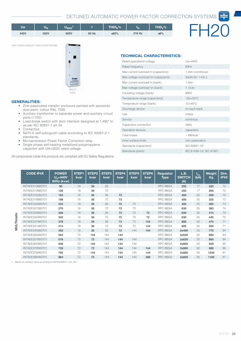
DETUNED AUTOMATIC POWER FACTOR CORRECTION SYSTEMS
FH20
GENERALITIES:• Zink-passivated metallic enclosure painted with epossidic
dust paint, colour RAL 7035.• Auxiliary transformer to separate power and auxiliary circuit
parts (110V).• Load-break switch with door interlock designed at 1,495* In
as per IEC 60831-1 art.34.• Contactors.• N07V-K self-extinguish cable according to IEC 50267-2-1
standards.• Microprocessor Power Factor Correction relay• Single phase self-healing metallized polypropylene
capacitor with UN=550V rated voltage
All components inside this products are compliant with EU Safety Regulations.
CODE IP4X POWERUe=440V
60Hz (kvar)
STEP1kvar
STEP2kvar
STEP3kvar
STEP4kvar
STEP5kvar
STEP6kvar
RegulatorType
L.B.SWITCH
(A)
ICC(kA)
WeightKg
Dim.IP4X
MU
LTIm
atic
IN7AEE312660701 90 18 36 36 RPC 8BGA 250 17 220 72IN7AEE312660701 126 18 36 72 RPC 8BGA 250 17 260 72IN7AEE316260701 162 18 36 36 72 RPC 8BGA 400 25 300 72IN7AEE319860701 198 18 36 72 72 RPC 8BGA 400 25 325 72IN7AEE323460701 234 18 36 36 72 72 RPC 8BGA 400 25 365 74IN7AEE327060701 270 18 36 72 72 72 RPC 8BGA 630 25 385 74IN7AEE330660701 306 18 36 36 72 72 72 RPC 8BGA 630 25 415 70IN7AEE334260701 342 18 36 72 72 72 72 RPC 8BGA 630 25 445 70IN7AEE337860701 378 18 36 36 72 72 144 RPC 8BGA 800 50 475 71IN7AEE341460701 414 18 36 72 72 72 144 RPC 8BGA 800 50 505 71IN7AEE345060701 450 18 36 36 72 144 144 RPC 8BGA 2x400 25 775 94IN7AEE350460701 504 72 144 144 144 RPC 8BGA 2x630 25 800 94IN7AEE357660701 576 72 72 144 144 144 RPC 8BGA 2x630 25 860 94IN7AEE364860701 648 72 144 144 144 144 RPC 8BGA 2x800 50 920 90IN7AEE372060701 720 72 72 144 144 144 144 RPC 8BGA 2x800 50 980 90IN7AEE379260701 792 72 144 144 144 144 144 RPC 8BGA 2x800 50 1040 91IN7AEE386460701 864 72 72 144 144 144 288 RPC 8BGA 2x800 50 1100 91
1. Maximum allowed value according to CEI EN 60831-1 art. 20.1
TECHNICAL CHARACTERISTICS:Rated operational voltage Ue=440V
Rated frequency 60Hz
Max current overload In (capacitors) 1,3xIn (continous)
Max voltage overload Vn (capacitors) 3xUN (for 1 min.)
Max current overload In (bank) 1.3xIn
Max voltage overload Vn (bank) 1.1xUe
Insulating voltage (bank) 690V
Temperature range (capacitors) -25/+55°C
Temperature range (bank) -5/+40°C
Discharge device on each bank
Use indoor
Service continous
Capacitors connection delta
Operation devices capacitors
Total losses ~ 6W/kvar
Inner surface fi nish zinc passivation
Standards (capacitors) IEC 60831-1/2
Standards (bank) IEC 61439-1/2, IEC 61921
Ue UN UMAX1 f THDIR% fN THDV%
440V 550V 600V 60 Hz ≤60% 216 Hz ≤6%
100% NON LINEAR LOAD IN NETWORK
MULTImatic
26

DETUNED AUTOMATIC POWER FACTOR CORRECTION SYSTEMS
FH30
GENERALITIES:• Zink-passivated metallic enclosure painted with
epossidic dust paint, colour RAL 7035.• Auxiliary transformer to separate power and auxiliary
circuit parts (110V).• Load-break switch with door interlock designed at
1,495* In as per IEC 60831-1 art.34.• Contactors.• N07V-K self-extinguish cable according to IEC
50267-2-1standards.• Microprocessor Power Factor Correction relay• Single phase self-healing metallized polypropylene
capacitor with UN=550V rated voltage
All components inside this products are compliant with EU Safety Regulations.
CODE IP4X POWERUe=400V
60Hz (kvar)
STEP1kvar
STEP2kvar
STEP3kvar
STEP4kvar
STEP5kvar
STEP6kvar
RegulatorType
L.B.SWITCH
(A)
ICC(kA)
WeightKg
Dim.IP4X
MU
LTIm
atic
FH
30
IN7JFF281060702 81 16 32,5 32,5 RPC 8BGA 250 17 220 72IN7JFF311460702 114 16 32,5 65 RPC 8BGA 250 17 260 72IN7JFF314660702 146 16 32,5 32,5 65 RPC 8BGA 400 25 300 72IN7JFF317960702 179 16 32,5 65 65 RPC 8BGA 400 25 325 72IN7JFF321160702 211 16 32,5 32,5 65 65 RPC 8BGA 630 25 365 74IN7JFF324460702 244 16 32,5 65 65 65 RPC 8BGA 630 25 385 74IN7JFF327660702 276 16 32,5 32,5 65 65 65 RPC 8BGA 630 25 415 70IN7JFF330960702 309 16 32,5 65 65 65 65 RPC 8BGA 800 50 445 70IN7JFF334160702 341 16 32,5 32,5 65 65 130 RPC 8BGA 800 50 475 71IN7JFF337460702 374 16 32,5 65 65 65 130 RPC 8BGA 800 50 505 71IN7JFF340660702 406 16 32,5 32,5 65 130 130 RPC 8BGA 2x630 25 775 94IN7JFF345560702 455 65 130 130 130 RPC 8BGA 2x630 25 800 94IN7JFF352060702 520 65 65 130 130 130 RPC 8BGA 2x630 25 860 94IN7JFF358560702 585 65 130 130 130 130 RPC 8BGA 2x800 50 920 90IN7JFF365060702 650 65 65 130 130 130 130 RPC 8BGA 2x800 50 980 90IN7JFF371560702 715 65 130 130 130 130 130 RPC 8BGA 2x800 50 1040 91IN7JFF378060702 780 65 65 130 130 130 260 RPC 8BGA 2x800 50 1100 91
1. Maximum allowed value according to CEI EN 60831-1 art. 20.1
TECHNICAL CHARACTERISTICS:Rated operational voltage Ue=400V
Rated frequency 60Hz
Max current overload In (capacitors) 1,3xIn (continous)
Max voltage overload Vn (capacitors) 3xUN (for 1 min.)
Max current overload In (bank) 1.3xIn
Max voltage overload Vn (bank) 1.1xUe
Insulating voltage (bank) 690V
Temperature range (capacitors) -25/+55°C
Temperature range (bank) -5/+40°C
Discharge device on each bank
Use indoor
Service continous
Capacitors connection delta
Operation devices capacitors
Total Joule losses ~ 8W/kvar
Inner surface fi nish zinc passivation
Standards (capacitors) IEC 60831-1/2
Standards (bank) IEC 61439-1/2, IEC 61921
Ue UN UMAX1 f THDIR% fN THDV%
400V 550V 600V 60 Hz >60% 162 Hz ≤6%
100% NON LINEAR LOAD IN NETWORK
MULTImatic
27

Power factor correction solutionswith metallized paper capacitors In this chapter you will find the following ranges
TC40 Fix Power Factor Correction Systems with metallized paper and 480V nominal voltage capacitors
FD40 Automatic Power Factor Correction Systems with detuning chokes and bimetallized paper capacitors.
CHAPTER 4
28

Range Part number Model Rated VoltageUN (V)
Max. VoltageUMAX (V)
Power(kvar)
Capacitance (μF)
Dim (cap7)
Weight(kg)
Pcs/box
TC10 CRMT250163400A0 CRM25-11A-2.50-400 400 440 2,5 50 60x138 0,5 36
TC20 - FD25 CRMM250163400A0 CRM25-11A-2.50-460 460 500 2,5 37 60x138 0,5 36
FD35 CRMR250163400A0 CRM25-11A-2.50-550 550 605 2,5 26 60x138 0,5 36
TECHNICAL CHARACTERISTICS:Rated operational voltage Ue=400-460-550V
Rated frequency 50Hz
Max current overload In 3xIn (continous)
Max voltage overload Vn 1.1xUN
Insulating voltage 3/15kV - Ue≤660Vac
Temperature range -25/+85°C
Capacitance tolerance -5÷+10%
Terminal voltage test 2.15xUN 10 sec
Service continous
Capacitors connection metallized paper
Standards IEC 60831-1/2
GENERALITIES:• Metallic case with protection degree IP00• Internal overpressure protection system• Oil impregnation vacuum packed.
All components inside this products are compliant with EU SafetyRegulations.
CYLINDRICAL SINGLE PHASE POWER CAPACITORS
CRM25
29
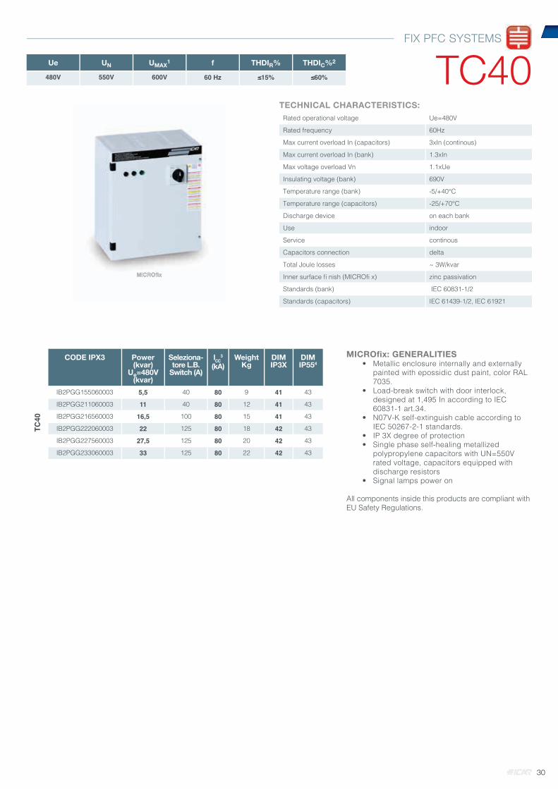
CODE IPX3 Power(kvar)
Ue=480V(kvar)
Seleziona-tore L.B.
Switch (A)
ICC3
(kA)Weight
KgDIMIP3X
DIMIP554
TC40
IB2PGG155060003 5,5 40 80 9 41 43
IB2PGG211060003 11 40 80 12 41 43
IB2PGG216560003 16,5 100 80 15 41 43
IB2PGG222060003 22 125 80 18 42 43
IB2PGG227560003 27,5 125 80 20 42 43
IB2PGG233060003 33 125 80 22 42 43
MICROfix: GENERALITIES• Metallic enclosure internally and externally
painted with epossidic dust paint, color RAL 7035.
• Load-break switch with door interlock, designed at 1,495 In according to IEC 60831-1 art.34.
• N07V-K self-extinguish cable according to IEC 50267-2-1 standards.
• IP 3X degree of protection• Single phase self-healing metallized
polypropylene capacitors with UN=550V rated voltage, capacitors equipped with discharge resistors
• Signal lamps power on
All components inside this products are compliant with EU Safety Regulations.
TECHNICAL CHARACTERISTICS:Rated operational voltage Ue=480V
Rated frequency 60Hz
Max current overload In (capacitors) 3xIn (continous)
Max current overload In (bank) 1.3xIn
Max voltage overload Vn 1.1xUe
Insulating voltage (bank) 690V
Temperature range (bank) -5/+40°C
Temperature range (capacitors) -25/+70°C
Discharge device on each bank
Use indoor
Service continous
Capacitors connection delta
Total Joule losses ~ 3W/kvar
Inner surface fi nish (MICROfi x) zinc passivation
Standards (bank) IEC 60831-1/2
Standards (capacitors) IEC 61439-1/2, IEC 61921
Ue UN UMAX1 f THDIR% THDIC%2
480V 550V 600V 60 Hz ≤15% ≤60%
MICROfi xMICROfi x
FIX PFC SYSTEMS
TC40
30
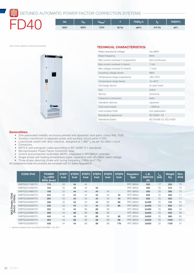
Generalities:• Zink-passivated metallic enclosure painted with epossidic dust paint, colour RAL 7035. • Auxiliary transformer to separate power and auxiliary circuit parts (110V).• Load-break switch with door interlock, designed at 1,495* In as per IEC 60831-1 art.34• Contactors.• N07V-K self-extinguish cable according to IEC 50267-2-1 standards.• Microprocessor Power Factor Correction relay• Control and protection multimeter MCP5, integrated in RPC8BGA controller.• Single phase self-healing bimetallized paper capacitors with UN=660V rated voltage.• Three phase detuning choke with tuning frequency 216Hz (p=7,7%).
All components inside this products are compliant with EU Safety Regulations.
CODE IP4X POWERUe=480V
60Hz (kvar)
STEP1kvar
STEP2kvar
STEP3kvar
STEP4kvar
STEP5kvar
STEP6kvar
RegulatorType
L.B.SWITCH
(A)
ICC(kA)
WeightKg
Dim.IP4X
MU
LTIm
atic
FD
40(N
=3.6
- 21
6Hz)
IN8PGG311060701 110 22 44 44 RPC 8BGA 250 17 250 72IN8PGG315460701 154 22 44 44 44 RPC 8BGA 400 25 315 74IN8PGG319860701 198 22 44 44 44 44 RPC 8BGA 400 25 380 70IN8PGG324260701 242 22 44 44 44 44 44 RPC 8BGA 630 25 460 71IN8PGG326460701 264 44 44 44 44 44 44 RPC 8BGA 630 25 520 71IN8PGG330860701 308 22 22 44 44 88 88 RPC 8BGA 2x400 25 740 94IN8PGG333060701 330 22 44 44 44 88 88 RPC 8BGA 2x400 25 800 94IN8PGG335260701 352 44 44 88 88 88 RPC 8BGA 2x400 25 860 94IN8PGG339660701 396 44 88 88 88 88 RPC 8BGA 2x630 25 920 90IN8PGG344060701 440 44 44 88 88 88 88 RPC 8BGA 2x630 25 980 90IN8PGG348460701 484 44 88 88 88 88 88 RPC 8BGA 2x630 25 1040 91IN8PGG352860701 528 44 44 88 88 88 176 RPC 8BGA 2x630 25 1100 91
1. Maximum allowed value according to IEC 60831-1 art. 20.1
TECHNICAL CHARACTERISTICS:Rated operational voltage Ue=480V
Rated frequency 60Hz
Max current overload In (capacitors) 3xIn (continous)
Max current overload In (bank) 1.3xIn
Max voltage overload Vn (bank) 1.1xUe
Insulating voltage (bank) 690V
Temperature range (capacitors) -25/+70°C
Temperature range (bank) -5/+40°C
Discharge device on each bank
Use indoor
Service continous
Capacitors connection delta
Operation devices capacitors
Total Joule losses ~ 6W/kvar
Inner surface fi nish zinc passivation
Standards (capacitors) IEC 60831-1/2
Standards (bank) IEC 61439-1/2, IEC 61921
Ue UN UMAX1 f THDIR% fN THDV%
480V 660V 725V 60 Hz ≤60% 216 Hz ≤6%
DETUNED AUTOMATIC POWER FACTOR CORRECTION SYSTEMS
FD40100% NON LINEAR LOAD IN NETWORK
31

RPC 5LGA RPC 8BGA
Reactive power regulators and protections The reactive power regulator is, together with the capacitors and reactors (in detuned filter cabinets), the key component of the automatic power factor correction system. It is in fact the "intelligent" element, responsible for the verification of the power factor of the load, in function of which controls the switching on and off of the capacitors batteries in order to maintain the power factor of the system beyond the target.
The reactive power regulators RPC used in automatic ICAR power factor correction systems are designed to provide the desired power factor while minimizing the wearing on the banks of capacitors, accurate and reliable in measuring and control functions are simple and intuitive in installation and consultation.By purchasing a ICAR automatic power factor correction system you receive it ready for commissioning. In fact he controller is already set, you just need to connect it to the line CT and set the value of the primary current.The controller automatically recognizes the current direction of the CT secondary, to correct any wiring errors.The flexibility of ICAR regulators allows you to modify all the parameters to customize its operation to fit the actual characteristics of the system to be corrected (threshold power factor, sensitivity of step switching, reconnecting time of the steps, presence of photovoltaics, etc.).
As described below, the ICAR regulators offer important features as for the maintenance and management of the power factor correction bank, aimed at identifying and solving problems, which could lead to its damage with consequent life expectancy reduction.
System Range PFC Controller
MICROmatic RPC 5LGA
MINImatic RPC 5LGA+ MCP4 optional
MINImatic filter RPC 5LGA+ MCP4 optional
MULTImatic RPC 8BGA +MCP5 optional
MULTImatic filter RPC 8BGA +MCP5 in standard
CHAPTER 5
32

RPC 8BGA reactive power regulator The RPC 8BGA reactive power regulator equips MULTImatic automatic power factor correction systems.It is a very innovative controller, with exclusive features:
• High electrical performance• Extended Capabilities• Graphic display• Advanced communication• Upgradability, even after installation• Powerful supervision software
More details below, referring to the following page tables and manuals for further information.
High electrical performance: The 8BGA controller is equipped with powerful hardware, which allows a considerable electrical performances: it can be connected to the CT secondary 5A or 1A, it can work on networks with voltages from 100 to 600Vac with a measuring range from 75VAC to 760VAC, it can be connected to a single CT (typical configuration of the power factor correction) or three-CTs (for a more accurate measurement of the power factor, and this fact makes the 8BGA controller to refocus and to be a multimeter as well).
Extended Capabilities: The 8BGA reactive power regulator is controlled by a powerful microprocessor that allows a set of new functions to solve problems even in complex plant. 8BGA can work master-slave functions, handles up to 10 languages simultaneously, can be used in MV systems managing the transformation ratio of the VT, it can support multiple inputs and outputs via optional modules, it can handle target cos phi from 0.5 inductive to 0.5 capacitive. 8BGA can build a network of 4 wired units (one master three slaves) to be able to handle up to 32 steps of power factor correction in a consistent and uniform way.
Graphical display with high readability: forget the regulators with small displays and difficult to read: 8BGA will amaze you with its display matrix graphic LCD 128x80 pixels. The detail and sharpness allow intuitive navigation between the different menus, represented with text and icons.
Advanced communication: 8BGA born to be a regulator able to communicate in a manner in line with the latest technology: Ethernet, RS485, GSM / GPRS modem, USB, WIFI. Now you can see the information of the company cos phi, without having to go in front of the regulator. It will be the controller to inform you by posting, if you wish, SMS or email. Or you can consult a tablet, a smartphone, or PC. The information about the cos phi is important, because it impacts heavily on the company's income statement.
Evolutivity: the "basic" 8BGA regulator can be enhanched with up to four additional modules "plug and play" which greatly expands its performance.And 'possible to add additional control relays (up to a total of 16), even for a static control (thyristors), digital and analog inputs, analog outputs, communication modules.Your controller can become a small PLC, and the PFC system can become a point of data aggregation, for remote communication.
Measurement functionsand help to maintain8BGA is a real evolved multimeter, thanks also to the graphic display of excellent readability and to the powerful microprocessor .The measured parameters are the basic ones (cos phi, FP, V, I, P, Q, A, Ea, Er) with the addition of the distortion of the voltage and current (THD, histogram of the value of each harmonic, waveform graphic visualization).If 8BGA is connected to three CT, the harmonic analysis is detailed for each phase, in order to identify any anomalies of single phase loads.8BGA measure and count values that can help in ruling the PFC (temperature, number of switching of each step). 8BGA also suggests the maintenance to be carried out by means of simple messages on the display. Keep efficient capacitor becomes much easier.
8BGA stores the maximum values of current, voltage, temperature, each associated with the date and time of the event for a better analysis of what happened.
AlarmsThe set of alarms (maximum and minimum voltage, maximum and minimum current, over and under-compensation, overload of the capacitors, maximum temperature, microinterruption) associated with the readability of the messages on the display allows a better understanding of what happened. Even alarm programming (enable / disable, delay, relapse etc.) is easier and faster.
33

RPC 8BGA
8BGA Power Factor Correction Controller:technical parameters
CHARACTERISTICS• Supply Voltage: 100÷440Vac• Frequency: 50Hz/60Hz• Voltage Measuring range: 100÷690V (-15% / +10%)• Current Measuring range: 5A (1A selectable)• Current incoming range: from 25mA to 6A (from 10mA to 1,2A)• Automatic phase sequence reading: yes• Compensation in cogeneration: yes• Burden: 12 VA (10,5W)• Output relay current: 5A – 250Vac• Cos φ range: from 0,5 ind to 0,5 cap• Tan φ range: from -1,732 to + 1,732• Step switching time: 1s÷1000s (20ms in case of STR4NO)• Alarm relay: yes• Degree of protection: IP55• Working temperature range: from -30°C to +70°C• Storage temperature range: from -30°C to + 80°C• USB optic communication port (with COMUSB)• Temperature Control: from -30°C to +85°C• Standards compliance: IEC EN 61010-1; IEC/EN 61000-6-2;
IEC/EN 61000-6-3; UL508; CSA C22-2 n°14• Step output relays: 8 (expandable till 16, see expandability table)• Dimensions: 144x144mm• Weight: 0,98kg• Part number: A25060046411000
Graphic display 128x80 pixel
USB – WIFI Optic netportSelection, modification and enter push buttons.
LED watchdog and alarm
34

technology looking ahead
technology looking ahead
RPC 8BGA Power Factor Correction Controller: additional modulesThe RPC 8BGA controller accommodates up to 4 additional modules "plug & play".Once you have added an additional module, the controller recognizes and activates the menu for its programming.Additional modules can also be installed in the rear.
Digital inputs and outputsThese modules allow you to increase the contacts funding for control of the steps contactors (OUT2NO module) or thyristors (STR4NO module) switched banks, or to add inputs and / or digital / analog acquisition of parameters and implementing simple logic.
• OUT2NO module 2 digital outputs to control additional steps (two relays 5A 250 Vac)• STR4NO module 4 static outputs for thyristor control steps (range SPEED)• INP4OC module 4 digital inputs• 2IN2SO module 2 digital inputs and 2 static outputs• INP2AN module 2 analog inputs• OUT2AN module 2 analog outputs
Protection functions (MCP5) and data logging (DATLOG)The control and protection module MCP5 allows a more detailed inspection of the electrical parameter that can damage the capacitors, thanks to algorithms particularly suitable for equipment consisting of capacitors and reactors (detuned filters MULTImatic FH20, FH30, FD25, FD25V, FD35, FH70, FD70).The data logging module adds the ability to orodatare events, for a better understanding and diagnosis of troubled plants.
• MCP5 module for protection and control for additional safety of capacitors, especially suitable in the detuned banks• DATLOG data logger module with real time clock and battery backup for data retention
Communication functionsRPC 8BGA regulator is very powerful in terms of communication.The modules dedicated to these functions allow multiple solutions to remotely control the power factor system and all other variables measured, calculated or obtained from the instrument.
• COM232 isolated RS232 interface• COM485 RS485 opto-isolated• WEBETH Ethernet interface with webserver function• COMPRO isolated Profi bus-DP interface• COMGSM GPRS / GSM modem• CX01 cable connection from the RPC 8BGA
optical port to the USB port of the computer for programming, downloading / uploading data, diagnostics etc..
• CX02 device to connect the optical port in the PRC 8BGA via WIFI: for programming, downloading / uploading data, diagnostics etc..
• CX03 antenna quad band GSM (800/900/1800
App1
App available for WIFI interfacing with the RPC 8BGA controller via tablet or smartphone. For iOS and Android.You have the following functions:
• Set of up regulator• Sending commands• Reading information• Download information and data residing on board• Calculation of the economic benefi t brought by the capacitor in terms of
less penalties in the bill
1: contact Icar sales
35

Reactive power regulators and protections
RPC 5LGA reactive powerregulator The RPC 5LGA reactive power regulator equips MICROmatic and MINImatic, automatic power factor correction systems.It is a very innovative controller, with exclusive features:
• High electrical performance• Extended Capabilities• Graphic display• RS232-RS485 communication• Powerful supervision software
More details below, referring to the following page tables and manuals for further information.
High electrical performance: The 5LGA controller is equipped with powerful hardware, which allows a considerable electrical performances: it can be connected to the CT secondary 5A or 1A, it can work on networks with voltages from 100 to 600Vac with a measuring range from 50Vac to 720Vac.
Extended Capabilities: The 5LGA reactive power regulator is controlled by a powerful microprocessor, handles up to 6 languages simultaneously, can be used in MV systems managing the transformation ratio of the VT, it can handle target cos phi from 0.5 inductive to 0.5 capacitive.
Advanced communication: 5LGA born to be a regulator able to communicate in a manner in line with the latest technology: RS485.Now you can see the information of the company cos phi, without having to go in front of the regulator.The information about the cos phi is important, because it impacts heavily on the company's income statement.
Measurement functionsand help to maintain5LGA is a multimeter, thanks also to the graphic display of excellent readability and to the powerful microprocessor. The measured parameters are the basic ones (cos phi, FP, V, I) with the addition of the distortion of the voltage and current.5LGA measure and count values that can help in ruling the PFC (temperature, number of switching of each step).5LGA also suggests the maintenance to be carried out by means of simple messages on the display. Keep efficient capacitor becomes much easier. 5LGA stores the maximum values of current, voltage, temperature.
AlarmsThe set of alarms (maximum and minimum voltage, maximum and minimum current, over and under-compensation, overload of the capacitors, maximum temperature, microinterruption) associated with the readability of the messages on the display allows a better understanding of what happened.Even alarm programming (enable / disable, delay, relapse etc.) is easier and faster.
5LGA Power Factor CorrectionController: Technical parameters
TECHNICAL CHARACTERISTICS• Microprocessor control• Auxiliary supply voltage: 100 to 440 V AC• Frequency: 50Hz / 60Hz• Voltage measuring input : 100 to 600V• Current measuring input : 5A (1A pr ogrammable)• Current reading range: from 25mA to 6A
(from 25mA to 1.2A)• Automatic current way sensing: yes• Operation in systems with cogeneration: yes• Power consumption: 9.5 VA• Output relay : 5A - 250Vac• Cos φ adjustment: from 0.5 ind to 0.5 cap• Step Switching Time: 15s ÷ 1000s• Alarm relay: yes• Degree of protection: IP54 on front and IP20 at• terminals• Operating temperature: -20 ° C to + 60 ° C• Storage temperature: -30 ° C to + 80 ° C• Optical port Front: for communication USB or WIFI• with dedicated accessories• Compliance with the standards: IEC EN 61010-1;• IEC / EN 61000-6-2; IEC / EN 61000-6-4; UL508;• CSA C22-2 n ° 14
newnew
36
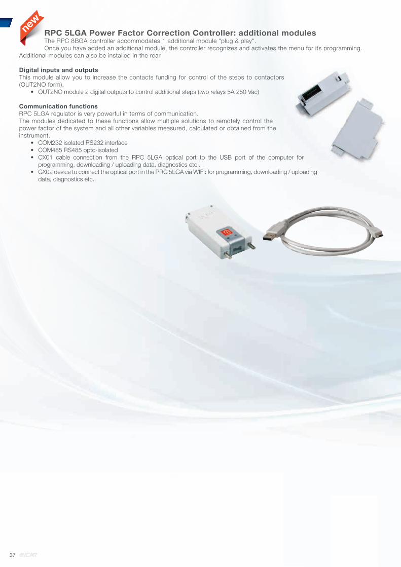
newRPC 5LGA Power Factor Correction Controller: additional modulesThe RPC 8BGA controller accommodates 1 additional module "plug & play".Once you have added an additional module, the controller recognizes and activates the menu for its programming.
Additional modules can also be installed in the rear.
Digital inputs and outputsThis module allow you to increase the contacts funding for control of the steps to contactors (OUT2NO form).
• OUT2NO module 2 digital outputs to control additional steps (two relays 5A 250 Vac)
Communication functionsRPC 5LGA regulator is very powerful in terms of communication.The modules dedicated to these functions allow multiple solutions to remotely control the power factor of the system and all other variables measured, calculated or obtained from the instrument.
• COM232 isolated RS232 interface• COM485 RS485 opto-isolated• CX01 cable connection from the RPC 5LGA optical port to the USB port of the computer for
programming, downloading / uploading data, diagnostics etc..• CX02 device to connect the optical port in the PRC 5LGA via WIFI: for programming, downloading / uploading
data, diagnostics etc..
37

Ø Drawing Ø A B C M
1 40 103 10 8
2 45 128 10 8
3 55 128 12,5 12
4 60 138 12,5 12
Drawing C C1 C2 C3 C4 C5
21 89
22 165
23 241
24 317
25 393
26 469
Dimensions CHAPTER 6
38

DIMENSIONS
41
42
43
51
A
39

51
52
5556
Top view with cable incoming inlet
Bottom view with cable incoming inlet
Applicable to drawings 55, 56, 57, 58
Fixing pads are removable
DIMENSIONS
A
40

57
58
DIMENSIONS
Fixing pads are removable
70
Applicable to drawings 70, 71, 73, 76, 77, 78
Floor fixing
Bottom view with cable incoming inlet
72
74
41

72
74
DIMENSIONS
1
1
2
2
3
3
4
4
5
5
6
6
7
7
8
8
A A
B B
C C
D D
E E
F FAPPROVEDDESCRIPTIONREV. DRAWNDATE DRAWING
FILE
PAGE
NEXT
PROJECT
CODETITLE
MO
D 0
4-0
5
AP
PR
.: R
QA
S
DIM
EN
SIO
NS
IN
mm
Tole
rance c
lass f
or
dim
ensio
ns
witho
ut
spe
cific
ind
ication
: IS
O 2
768
c
All r
igh
ts r
eserv
ed o
n t
his
dra
win
g.
An
y u
na
uth
orised
rep
rod
uctio
n o
r dis
trib
utio
n t
o t
hir
d p
art
ies
is s
tric
tly fo
rbid
den
610 610
670
100
16
00
17
60
1
1
2
2
3
3
4
4
5
5
6
6
7
7
8
8
A A
B B
C C
D D
E E
F FAPPROVEDDESCRIPTIONREV. DRAWNDATE DRAWING
FILE
PAGE
NEXT
PROJECT
CODETITLE
MO
D 0
4-0
5
AP
PR
.: R
QA
S
DIM
EN
SIO
NS
IN
mm
Tole
rance c
lass f
or
dim
ensio
ns
witho
ut
spe
cific
ind
ication
: IS
O 2
768
c
All r
igh
ts r
eserv
ed o
n t
his
dra
win
g.
An
y u
na
uth
orised
rep
rod
uctio
n o
r dis
trib
utio
n t
o t
hir
d p
art
ies
is s
tric
tly fo
rbid
den
610 610
670
10
01
80
0
19
60
42

90
Applicable to drawings 90, 91, 93, 95, 96, 98
DIMENSIONS
Bottom cable incoming inlet
Floor fixing
91
43

92
DIMENSIONS
94
1
1
2
2
3
3
4
4
5
5
6
6
7
7
8
8
A A
B B
C C
D D
E E
F FAPPROVEDDESCRIPTIONREV. DRAWNDATE DRAWING
FILE
PAGE
NEXT
PROJECT
CODETITLE
MO
D 0
4-0
5
AP
PR
.: R
QA
S
DIM
EN
SIO
NS
IN
mm
Tole
rance c
lass f
or
dim
ensio
ns
witho
ut
spe
cific
ind
ication
: IS
O 2
768
c
All r
igh
ts r
eserv
ed o
n t
his
dra
win
g.
An
y u
na
uth
orised
rep
rod
uctio
n o
r dis
trib
utio
n t
o t
hir
d p
art
ies
is s
tric
tly fo
rbid
den
610
670
605605
1210
10
0168
0
17
80
1
1
2
2
3
3
4
4
5
5
6
6
7
7
8
8
A A
B B
C C
D D
E E
F FAPPROVEDDESCRIPTIONREV. DRAWNDATE DRAWING
FILE
PAGE
NEXT
PROJECT
CODETITLE
MO
D 0
4-0
5
AP
PR
.: R
QA
S
DIM
EN
SIO
NS
IN
mm
Tole
rance c
lass f
or
dim
ensio
ns
witho
ut
spe
cific
ind
ication
: IS
O 2
768
c
All r
igh
ts r
eserv
ed o
n t
his
dra
win
g.
An
y u
na
uth
orised
rep
rod
uctio
n o
r dis
trib
utio
n t
o t
hir
d p
art
ies
is s
tric
tly fo
rbid
den
605 605
1210
610
670
10
018
80
198
0
44

K factor for turning active power into reactive power to achieve target power factor.
Existing Power Factor
Target Power Factor
0,9 0,91 0,92 0,93 0,94 0,95 0,96 0,97 0,98 0,990,30 2,695 2,724 2,754 2,785 2,817 2,851 2,888 2,929 2,977 3,0370,31 2,583 2,611 2,641 2,672 2,704 2,738 2,775 2,816 2,864 2,9240,32 2,476 2,505 2,535 2,565 2,598 2,632 2,669 2,710 2,758 2,8180,33 2,376 2,405 2,435 2,465 2,498 2,532 2,569 2,610 2,657 2,7180,34 2,282 2,310 2,340 2,371 2,403 2,437 2,474 2,515 2,563 2,6230,35 2,192 2,221 2,250 2,281 2,313 2,348 2,385 2,426 2,473 2,5340,36 2,107 2,136 2,166 2,196 2,229 2,263 2,300 2,341 2,388 2,4490,37 2,027 2,055 2,085 2,116 2,148 2,182 2,219 2,260 2,308 2,3680,38 1,950 1,979 2,008 2,039 2,071 2,105 2,143 2,184 2,231 2,2920,39 1,877 1,905 1,935 1,966 1,998 2,032 2,069 2,110 2,158 2,2190,40 1,807 1,836 1,865 1,896 1,928 1,963 2,000 2,041 2,088 2,1490,41 1,740 1,769 1,799 1,829 1,862 1,896 1,933 1,974 2,022 2,0820,42 1,676 1,705 1,735 1,766 1,798 1,832 1,869 1,910 1,958 2,0180,43 1,615 1,644 1,674 1,704 1,737 1,771 1,808 1,849 1,897 1,9570,44 1,557 1,585 1,615 1,646 1,678 1,712 1,749 1,790 1,838 1,8980,45 1,500 1,529 1,559 1,589 1,622 1,656 1,693 1,734 1,781 1,8420,46 1,446 1,475 1,504 1,535 1,567 1,602 1,639 1,680 1,727 1,7880,47 1,394 1,422 1,452 1,483 1,515 1,549 1,586 1,627 1,675 1,7360,48 1,343 1,372 1,402 1,432 1,465 1,499 1,536 1,577 1,625 1,6850,49 1,295 1,323 1,353 1,384 1,416 1,450 1,487 1,528 1,576 1,6370,50 1,248 1,276 1,306 1,337 1,369 1,403 1,440 1,481 1,529 1,5900,51 1,202 1,231 1,261 1,291 1,324 1,358 1,395 1,436 1,484 1,5440,52 1,158 1,187 1,217 1,247 1,280 1,314 1,351 1,392 1,440 1,5000,53 1,116 1,144 1,174 1,205 1,237 1,271 1,308 1,349 1,397 1,4580,54 1,074 1,103 1,133 1,163 1,196 1,230 1,267 1,308 1,356 1,4160,55 1,034 1,063 1,092 1,123 1,156 1,190 1,227 1,268 1,315 1,3760,56 0,995 1,024 1,053 1,084 1,116 1,151 1,188 1,229 1,276 1,3370,57 0,957 0,986 1,015 1,046 1,079 1,113 1,150 1,191 1,238 1,2990,58 0,920 0,949 0,979 1,009 1,042 1,076 1,113 1,154 1,201 1,2620,59 0,884 0,913 0,942 0,973 1,006 1,040 1,077 1,118 1,165 1,2260,60 0,849 0,878 0,907 0,938 0,970 1,005 1,042 1,083 1,130 1,1910,61 0,815 0,843 0,873 0,904 0,936 0,970 1,007 1,048 1,096 1,1570,62 0,781 0,810 0,839 0,870 0,903 0,937 0,974 1,015 1,062 1,1230,63 0,748 0,777 0,807 0,837 0,870 0,904 0,941 0,982 1,030 1,0900,64 0,716 0,745 0,775 0,805 0,838 0,872 0,909 0,950 0,998 1,0580,65 0,685 0,714 0,743 0,774 0,806 0,840 0,877 0,919 0,966 1,0270,66 0,654 0,683 0,712 0,743 0,775 0,810 0,847 0,888 0,935 0,9960,67 0,624 0,652 0,682 0,713 0,745 0,779 0,816 0,857 0,905 0,9660,68 0,594 0,623 0,652 0,683 0,715 0,750 0,787 0,828 0,875 0,9360,69 0,565 0,593 0,623 0,654 0,686 0,720 0,757 0,798 0,846 0,9070,70 0,536 0,565 0,594 0,625 0,657 0,692 0,729 0,770 0,817 0,8780,71 0,508 0,536 0,566 0,597 0,629 0,663 0,700 0,741 0,789 0,8490,72 0,480 0,508 0,538 0,569 0,601 0,635 0,672 0,713 0,761 0,8210,73 0,452 0,481 0,510 0,541 0,573 0,608 0,645 0,686 0,733 0,7940,74 0,425 0,453 0,483 0,514 0,546 0,580 0,617 0,658 0,706 0,7660,75 0,398 0,426 0,456 0,487 0,519 0,553 0,590 0,631 0,679 0,7390,76 0,371 0,400 0,429 0,460 0,492 0,526 0,563 0,605 0,652 0,7130,77 0,344 0,373 0,403 0,433 0,466 0,500 0,537 0,578 0,626 0,6860,78 0,318 0,347 0,376 0,407 0,439 0,474 0,511 0,552 0,599 0,6600,79 0,292 0,320 0,350 0,381 0,413 0,447 0,484 0,525 0,573 0,6340,80 0,266 0,294 0,324 0,355 0,387 0,421 0,458 0,499 0,547 0,6080,81 0,240 0,268 0,298 0,329 0,361 0,395 0,432 0,473 0,521 0,5810,82 0,214 0,242 0,272 0,303 0,335 0,369 0,406 0,447 0,495 0,5560,83 0,188 0,216 0,246 0,277 0,309 0,343 0,380 0,421 0,469 0,5300,84 0,162 0,190 0,220 0,251 0,283 0,317 0,354 0,395 0,443 0,5030,85 0,135 0,164 0,194 0,225 0,257 0,291 0,328 0,369 0,417 0,4770,86 0,109 0,138 0,167 0,198 0,230 0,265 0,302 0,343 0,390 0,4510,87 0,082 0,111 0,141 0,172 0,204 0,238 0,275 0,316 0,364 0,4240,88 0,055 0,084 0,114 0,145 0,177 0,211 0,248 0,289 0,337 0,3970,89 0,028 0,057 0,086 0,117 0,149 0,184 0,221 0,262 0,309 0,3700,90 - 0,029 0,058 0,089 0,121 0,156 0,193 0,234 0,281 0,3420,91 - - 0,030 0,060 0,093 0,127 0,164 0,205 0,253 0,3130,92 - - - 0,031 0,063 0,097 0,134 0,175 0,223 0,2840,93 - - - - 0,032 0,067 0,104 0,145 0,192 0,2530,94 - - - - - 0,034 0,071 0,112 0,160 0,2200,95 - - - - - - 0,037 0,078 0,126 0,186
APPENDIX
45

MV/LV transformer No Load Power Factor.
Transformer Power kVA OilTransformer
kvar
Cast Resin Transformer
kvar10 1 1,5
20 2 1,7
50 4 2
75 5 2,5
100 5 2,5
160 7 4
200 7,5 5
250 8 7,5
315 10 7,5
400 12,5 8
500 15 10
630 17,5 12,5
800 20 15
1000 25 17,5
1250 30 20
1600 35 22
2000 40 25
2500 50 35
3150 60 50
Three Phase Asynchronous Motors. Special care to self-excitation.
Motor Power Reactive Power (kvar)
HP kW 3000 rpm
1500 rpm
1000 rpm
750 rpm
500 rpm
0,4 0,55 - - 0,5 0,5 -
1 0,73 0,5 0,5 0,6 0,6 -
2 1,47 0,8 0,8 1 1 -
3 2,21 1 1 1,2 1,6 -
5 3,68 1,6 1,6 2 2,5 -
7 5,15 2 2 2,5 3 -
10 7,36 3 3 4 4 5
15 11 4 5 5 6 6
30 22,1 10 10 10 12 15
50 36,8 15 20 20 25 25
100 73,6 25 30 30 30 40
150 110 30 40 40 50 60
200 147 40 50 50 60 70
250 184 50 60 60 70 80
46
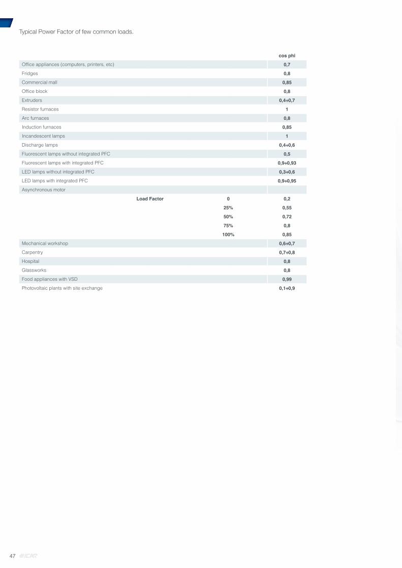
Typical Power Factor of few common loads.
cos phi
Offi ce appliances (computers, printers, etc) 0,7
Fridges 0,8
Commercial mall 0,85
Offi ce block 0,8
Extruders 0,4÷0,7
Resistor furnaces 1
Arc furnaces 0,8
Induction furnaces 0,85
Incandescent lamps 1
Discharge lamps 0,4÷0,6
Fluorescent lamps without integrated PFC 0,5
Fluorescent lamps with integrated PFC 0,9÷0,93
LED lamps without integrated PFC 0,3÷0,6
LED lamps with integrated PFC 0,9÷0,95
Asynchronous motor
Load Factor 0 0,2
25% 0,55
50% 0,72
75% 0,8
100% 0,85
Mechanical workshop 0,6÷0,7
Carpentry 0,7÷0,8
Hospital 0,8
Glassworks 0,8
Food appliances with VSD 0,99
Photovoltaic plants with site exchange 0,1÷0,9
47

www.icar.comOn internet ICAR web you’ll find,more information about PFC:
• ANY NEWS• REFERENCES• ICAR SERVICES• ALL DOCUMENTS FOR DOWNLOAD
• manuals• catalogues and brochures• technical newsletters for
• quick installation guidelines• CT selection and positioning• Selection of PFC in case of photovoltaic plants• Selection and tuning of PFC upstream protections• Selection table for heavily polluted and resonance risk plants• Selection table for replacement of old controllers• Meaning of error messages and problem solvinge
Similar informationis available forMV Power Factor Correction

COLT
ADV.IT
ICC
A01A
0715
E
ICAR S.p.A.Via Isonzo, 1020900 Monza (MB) - Italytel. +39 039 83.951fax +39 039 [email protected]
TECHNICAL FEATURES AND DIMENSIONS OF THIS CATALOGUE CAN BE CHANGED WITHOUT ICAR PRIOR NOTICE.ICAR DECLINES ANY RESPONSIBILITY FOR DAMAGES TO HUMANS OR OBJECTS FROM WRONG SELECTION OR USE OF ICAR MADE PRODUCTS.