catalysis science & technology - university of notre … of engineering, temple university, ......
TRANSCRIPT
CatalysisScience &Technology
PAPER
Cite this: Catal. Sci. Technol., 2016,
6, 5737
Received 1st April 2016,Accepted 19th April 2016
DOI: 10.1039/c6cy00734a
www.rsc.org/catalysis
Plastically deformed Cu-based alloys as high-performance catalysts for the reduction of4-nitrophenol†‡
Eredzhep Menumerov,§ Kyle D. Gilroy,§¶ Maryam Hajfathalian, Colin J. Murphy,Erica R. McKenzie, Robert A. Hughes and Svetlana Neretina*
The severe plastic deformation of metals leads to the formation of nanotextured surfaces as well as the re-
tention of significant strain energy, characteristics which are known to promote catalytic activity. Here, we
demonstrate plastically deformed surfaces of copper and copper-based alloys as being highly catalytic
using the well-studied model catalytic reaction which reduces 4-nitrophenol to 4-aminophenol by boro-
hydride. Among the materials studied, the most catalytically active is formed in a two-step process where
metal chips are mechanically sheared from a Cu–Sn alloy containing precipitates and then exposed to an
etchant which removes the precipitates from the exposed surface. The so-formed structures exhibit ex-
ceedingly high catalytic activity and set new benchmarks when incorporated into a fixed-bed reactor. The
formation of catalytically active sites is shown to be strongly dependent on the presence of the precipitates
during the deformation process, achieving an order of magnitude increase in the reaction rate constant
when compared to similarly formed Cu–Sn catalysts lacking these precipitates. The work, therefore, dem-
onstrates a new approach for generating catalytically active sites which may be applicable to other alloy
combinations.
Introduction
While the catalytic activity stemming from high-surface-area-to-volume structures with sub-15 nm dimensions is well-docu-mented,1 the corresponding reaction rates per unit surfacearea do not necessarily exceed those of complex mesoscopicor monolithic structures exhibiting surfaces with a nanoscaleroughness characterized by a high density of atomic steps,kinks, and undercoordinated atoms.2–12 In a scenario wherethe higher catalytic activity of these complex surfaces offsetsdeficiencies in terms of a low surface-area-to-volume ratiothere is the potential to advance an alternate catalytic plat-form which supersedes existing systems.
In addition to its technological relevance, the reactionwhich reduces 4-nitrophenol (4-NP) to 4-aminophenol (4-AP)by borohydride serves as an important model reaction for
assessing metallic nanostructures as catalytic materials. Con-sequently, there exists a vast literature commenting on theadvantages and disadvantages of various catalytic materialsand their supports.13,14 From a practical standpoint, numer-ous factors come into play when assessing a catalyst includ-ing mass and specific catalytic activities, price, weight, dura-bility, recoverability, selectivity, and ease of fabrication. Amechanistic understanding of what constitutes a highly cata-lytic surface for the reduction of 4-NP, however, is most read-ily obtained from a determination of the reaction rate con-stant per unit surface area of catalyst (i.e., kapp/area). Whilesuch a metric is of obvious significance, it is rarely reportedand, from an experimental standpoint, difficult to determineaccurately. As a result, it is often equally difficult to ascertainwhether high reaction rates arise from an intrinsically activesurface or the large total surface area attainable when usingan ensemble of small nanoparticles.
The plastic deformation of metals provides the means totransform a nominally flat metallic surface into one whichundulates on length-scales which depend upon the mechani-cal forces applied.15,16 Metals yield plastically when the ap-plied load perturbs the strain fields of dislocations to the ex-tent that they propagate though the material along slipbands, often intersecting with the surface and, hence,distorting it, a process which inevitably leads to a surfacewith steps, kinks, and undercoordinated atoms. Moreover,
Catal. Sci. Technol., 2016, 6, 5737–5745 | 5737This journal is © The Royal Society of Chemistry 2016
College of Engineering, Temple University, Philadelphia, Pennsylvania, 19122,
USA. E-mail: [email protected]
† The authors declare no competing financial interests.‡ Electronic supplementary information (ESI) available: Videos showing thefixed-bed reactor in operation; catalyst preparation conditions; additional cata-lyst characterization. See DOI: 10.1039/c6cy00734a§ These authors contributed equally.¶ Current Address for K. D. G: The Wallace H. Coulter Department of BiomedicalEngineering, Georgia Institute of Technology and Emory University, Atlanta,Georgia 30332, USA.
Publ
ishe
d on
20
Apr
il 20
16. D
ownl
oade
d by
Uni
vers
ity o
f N
otre
Dam
e on
31/
08/2
016
20:3
1:34
.
View Article OnlineView Journal | View Issue
5738 | Catal. Sci. Technol., 2016, 6, 5737–5745 This journal is © The Royal Society of Chemistry 2016
these same mechanical forces can lead to the generation ofnew dislocations which can respond likewise. The catalyticactivation of metal surfaces through elastic and plastic defor-mation has long been recognized.17–20 With nanoscale con-trol over the strains at lattice-mismatched heteroepitaxial in-terfaces in core–shell and bimetallic nanoparticles beingincreasingly realized, there is renewed interest in manipulat-ing these elastic strains to promote optimum catalyticbehavior21–27 as prescribed by volcano plot concepts andSabatier's principle.28 No such resurgence in interest, how-ever, currently exists for the case of plastic deformation, al-though it could play an important role in the formation ofthe dealloyed ligaments which make up nanoporous Aucatalysts.29–32 Here, we demonstrate that the catalytic activityof Cu-based metals can be intensified through plastic defor-mation and, when suitably combined with an etching proce-dure, exhibit catalytically active surfaces which, in mostcases, outperform nanoscale catalysts in the reduction of4-NP when evaluated in terms of specific catalytic activity(i.e., kapp/area). The so-formed catalysts are both inexpensiveand easily fabricated and, when incorporated into a fixed-bedsystem for continuous-flow reactions, are able to outperformtheir nanoscale counterparts by a wide margin.
Results and discussionCatalytically activating single crystals of Cu through plasticdeformation
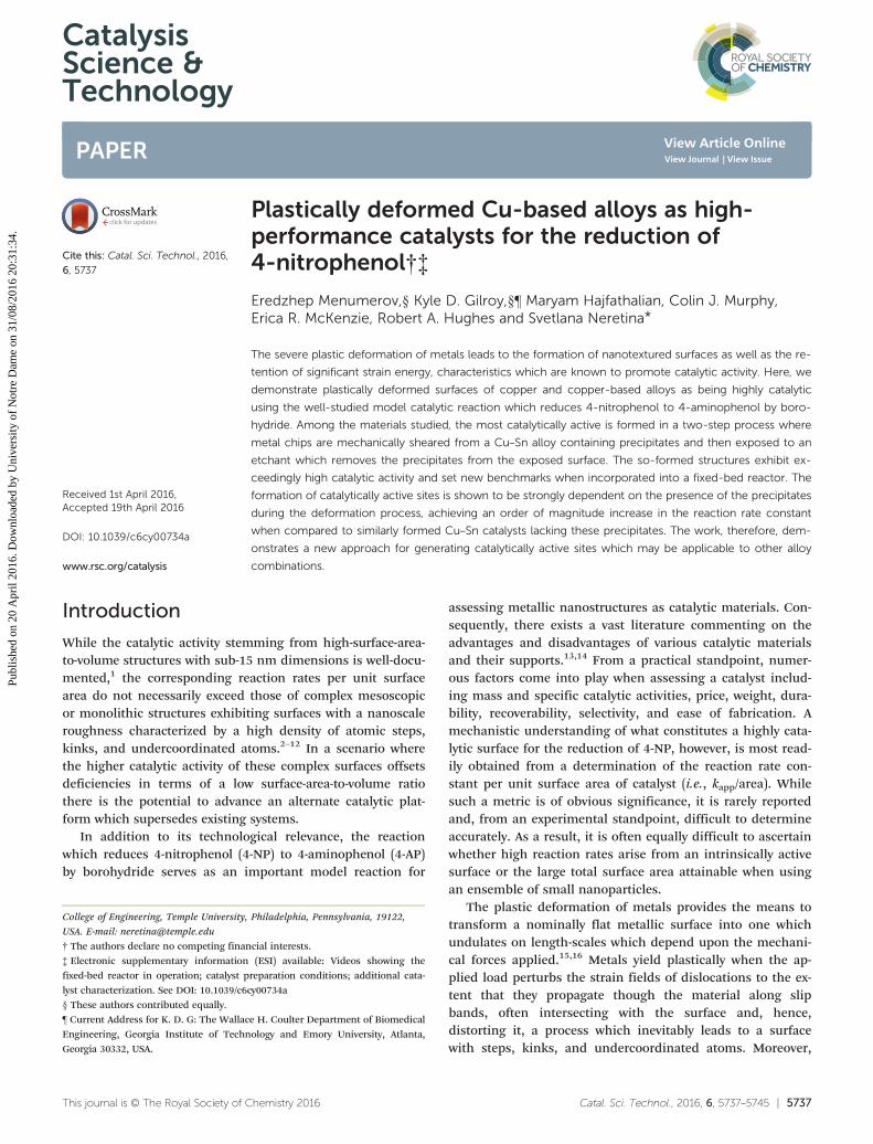
The mechanical activation of Cu surfaces through plastic de-formation was first assessed using polished single crystals.While such samples are impractical from the standpoint ofapplications, their use here allows for a more definitive as-signment of the catalytically active sites since theconfounding influence of grain boundaries is removed.Fig. 1a–c shows scanning electron microscopy (SEM) imagesof the surfaces of [100]-, [110]-, and [111]-oriented crystals af-ter being plastically bent around a cylindrical surface with aradius of curvature of 2 cm. All of the surfaces exhibit thecharacteristic linear features associated with slip bands in
face centered cubic crystals. Such features originate from thepropagation and subsequent intersection of numerous edgedislocations with the crystalline surface in response to an ex-ternally applied load. The ordered nature of the surface re-construction originates from a strong tendency toward slip-page of the {111} close-packed planes in a <110> direction.The geometric patterns formed by the slip bands for the dif-ferent crystallographic orientations, therefore, correspond tothe directions by which {111} planes intersect the varioussurfaces.
The assessment of catalytic activity for both the as-received and plastically deformed surfaces toward the reduc-tion of 4-NP was made using well-established spectroscopictechniques,13,14 where the Cu crystals were deployed using adip catalyst modality.33–35 The results reveal an enhancementto the reaction rate constant, kapp, resulting from plastic de-formation for all orientations (Fig. 1d). It demonstrates thatthe plastic deformation of Cu gives rise to catalytically activesurface sites in the absence of grain boundaries irrespectiveof the crystallographic surface orientation. It should, how-ever, be recognized that grain boundary influences mayheighten catalytic activity when using polycrystallinematerials.36–38
Catalytically activating Cu and Cu-based alloys through ashear deformation
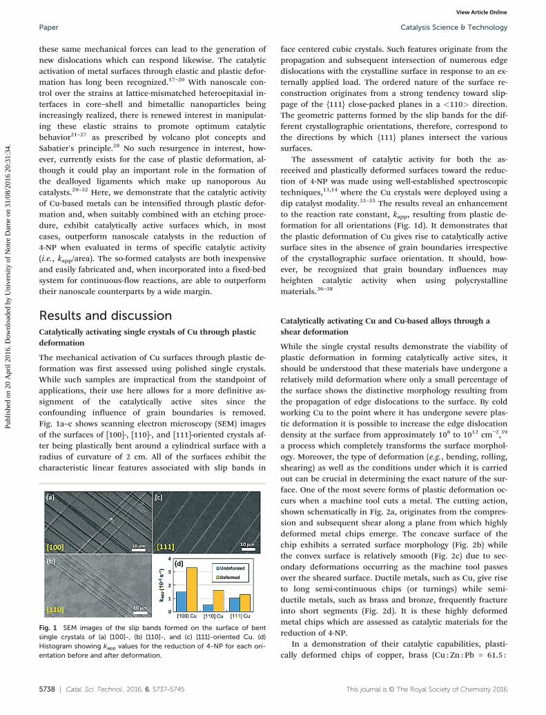
While the single crystal results demonstrate the viability ofplastic deformation in forming catalytically active sites, itshould be understood that these materials have undergone arelatively mild deformation where only a small percentage ofthe surface shows the distinctive morphology resulting fromthe propagation of edge dislocations to the surface. By coldworking Cu to the point where it has undergone severe plas-tic deformation it is possible to increase the edge dislocationdensity at the surface from approximately 108 to 1012 cm−2,39
a process which completely transforms the surface morphol-ogy. Moreover, the type of deformation (e.g., bending, rolling,shearing) as well as the conditions under which it is carriedout can be crucial in determining the exact nature of the sur-face. One of the most severe forms of plastic deformation oc-curs when a machine tool cuts a metal. The cutting action,shown schematically in Fig. 2a, originates from the compres-sion and subsequent shear along a plane from which highlydeformed metal chips emerge. The concave surface of thechip exhibits a serrated surface morphology (Fig. 2b) whilethe convex surface is relatively smooth (Fig. 2c) due to sec-ondary deformations occurring as the machine tool passesover the sheared surface. Ductile metals, such as Cu, give riseto long semi-continuous chips (or turnings) while semi-ductile metals, such as brass and bronze, frequently fractureinto short segments (Fig. 2d). It is these highly deformedmetal chips which are assessed as catalytic materials for thereduction of 4-NP.
In a demonstration of their catalytic capabilities, plasti-cally deformed chips of copper, brass (Cu : Zn : Pb = 61.5 :
Fig. 1 SEM images of the slip bands formed on the surface of bentsingle crystals of (a) [100]-, (b) [110]-, and (c) [111]-oriented Cu. (d)Histogram showing kapp values for the reduction of 4-NP for each ori-entation before and after deformation.
Catalysis Science & TechnologyPaper
Publ
ishe
d on
20
Apr
il 20
16. D
ownl
oade
d by
Uni
vers
ity o
f N
otre
Dam
e on
31/
08/2
016
20:3
1:34
. View Article Online
Catal. Sci. Technol., 2016, 6, 5737–5745 | 5739This journal is © The Royal Society of Chemistry 2016
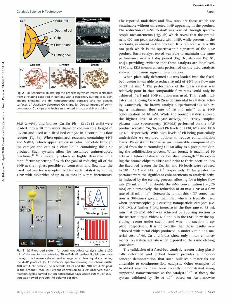
36.5 : 2 wt%), and bronze (Cu : Sn : Pb = 81 : 7 : 12 wt%) wereloaded into a 10 mm inner diameter column to a height of8.5 cm and used as a fixed-bed catalyst in a continuous-flowreactor (Fig. 3a). When optimized, reactants containing 4-NPand NaBH4, which appear yellow in color, percolate throughthe catalyst and exit as a clear liquid containing the 4-APproduct. Such systems allow for sustained uninterruptedreactions,40–42 a modality which is highly desirable in amanufacturing setting.43 With the goal of reducing all of the4-NP at the highest possible concentration and flow rate, thefixed bed reactor was optimized for each catalyst by adding4-NP with molarities of up to 30 mM in 5 mM increments.
The reported molarities and flow rates are those which aresustainable without unreacted 4-NP appearing in the product.The reduction of 4-NP to 4-AP was verified through spectro-scopic measurements (Fig. 3b) which reveal that the promi-nent 400 nm peak associated with 4-NP, while present in thereactants, is absent in the product. It is replaced with a 300nm peak which is the spectroscopic signature of the 4-APproduct. Each catalyst tested was able to maintain the sameperformance over a 7 day period (Fig. 3c, also see Fig. S1,ESI‡), providing evidence that these catalysts are long-lived.SEM and EDS measurements performed on the used catalystsshowed no obvious signs of deterioration.
When plastically deformed Cu was loaded into the fixed-bed reactor it was able to reduce 10 mM of 4-NP at a flow rateof 13 mL min−1. The performance of the brass catalyst wasrelatively poor in that comparable flow rates could only beachieved if a 5 mM 4-NP solution was used. This result indi-cates that alloying Cu with Zn is detrimental to catalytic activ-ity. Conversely, the bronze catalyst outperformed Cu, achiev-ing a maximum flow rate of 16 mL min−1 at a 4-NPconcentration of 10 mM. While the bronze catalyst showedthe highest level of catalytic activity, inductively coupledplasma mass spectrometry (ICP-MS) performed on the 4-APproduct revealed Cu, Sn, and Pb levels of 2230, 67.9 and 1810μg L−1, respectively. With high levels of Pb being particularlyundesirable we explored options to reduce contaminationlevels. Pb exists in bronze as an immiscible component ex-pelled from the surrounding Cu–Sn alloy as a precipitate dur-ing the solidification process. When bronze is machined Pbacts as a lubricant due to its low shear strength.44 By expos-ing the bronze chips to nitric acid prior to their insertion intothe fixed-bed reactor the Cu, Sn, and Pb levels were reducedto 1010, 59.2 and 248 μg L−1, respectively. Of far greater im-portance were the significant enhancements to catalytic activ-ity induced by the etching process, allowing for a higher flowrate (23 mL min−1) at double the 4-NP concentration (i.e., 20mM) or, alternatively, the reduction of 30 mM 4-NP at a flowrate of 15 mL min−1. Noteworthy is that this 4-NP concentra-tion is 300-times greater than that which is typically usedwhen spectroscopically assessing nanoparticle catalysts (i.e.100 μM). A further 3-fold increase in the flow rate to 63 mLmin−1 at 20 mM 4-NP was achieved by applying suction tothe reactor output. Videos S1a and b in the ESI‡ show the op-erating reactor under suction and when no suction is ap-plied, respectively. It is noteworthy that these results wereachieved with metal chips produced in under 5 min at a ma-terial cost of 6¢. Cu and brass show only minor enhance-ments to catalytic activity when exposed to the same etchingprocedure.
The validation of a fixed-bed catalytic reactor using plasti-cally deformed and etched bronze provides a proof-of-concept demonstration that such bulk-scale materials areamenable to continuous-flow catalysis. Other examples offixed-bed reactors have been recently demonstrated usingsupported nanostructures as the catalyst.37–39 Of these, thesystem validated by He et al.40 based on Au nanowire
Fig. 2 (a) Schematic illustrating the process by which metal is shearedfrom a rotating solid rod in contact with a stationary cutting tool. SEMimages showing the (b) nanostructured concave and (c) convexsurfaces of plastically deformed Cu chips. (d) Optical images of semi-continuous Cu chips and highly segmented bronze and brass chips.
Fig. 3 (a) Fixed-bed system for continuous-flow catalysis where 100mL of the reactants containing 30 mM 4-NP (yellow liquid) percolatethrough the bronze catalyst and emerge as a clear liquid containingthe 4-AP product. (b) Absorbance spectra showing the characteristic400 nm 4-NP peak in the reactants (blue) and the 300 nm 4-AP peakin the product (red). (c) Percent conversion to 4-AP observed over 7reaction cycles carried out on consecutive days where 100 mL of solu-tion was flowed through the column per day.
Catalysis Science & Technology Paper
Publ
ishe
d on
20
Apr
il 20
16. D
ownl
oade
d by
Uni
vers
ity o
f N
otre
Dam
e on
31/
08/2
016
20:3
1:34
. View Article Online
5740 | Catal. Sci. Technol., 2016, 6, 5737–5745 This journal is © The Royal Society of Chemistry 2016
catalysts affixed to glass fiber supports, shows the most im-pressive capabilities. The bronze catalyst is, however, able toreact 4-NP at twice the rate under both evacuated and regularflow conditions, a result which attests to the viability of usingplastic deformation as a means to fabricate catalytically activesurfaces. Additional advantages which these catalysts haveover their nanoscale counterparts include: (i) the eliminationof difficulties associated with catalyst anchoring and aggrega-tion,40 (ii) a catalyst fabrication process which is free of li-gands which can inhibit the catalytic activity ofnanoparticles45–47 and are a potential product contaminant,(iii) a catalyst synthesis which is rapid, inexpensive, and scal-able, and (iv) the use of bronze which, when compared tocurrent nanoscale catalysts such as Au and Pd, is far morecost-effective. In fact, bronze chips are already produced inlarge quantities as a byproduct of manufacturing processes;their use as a catalyst provides the prospect of using what isnominally a waste product as a functional material.
Characterization of the Cu–Sn alloy catalyst
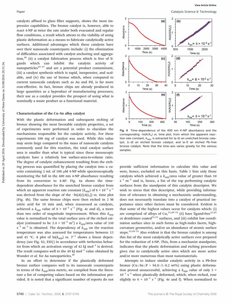
With the plastic deformation and subsequent etching ofbronze showing the most favorable catalytic properties, a setof experiments were performed in order to elucidate themechanisms responsible for the catalytic activity. For theseexperiments 100 mg of catalyst was used. While this valuemay seem large compared to the mass of nanoscale catalystscommonly used for this reaction, the total catalyst surfacearea is smaller than what is typical since these mesoscopiccatalysts have a relatively low surface-area-to-volume ratio.The degree of catalytic enhancement resulting from the etch-ing process was quantified by placing the catalyst into a cu-vette containing 2 mL of 100 μM 4-NP while spectroscopicallymonitoring the fall in the 400 nm 4-NP absorbance resultingfrom its conversion to 4-AP. Fig. 4a shows the time-dependent absorbance for the unetched bronze catalyst fromwhich an apparent reaction rate constant (kapp) of 6 × 10⁻⁴ s−1
was derived from the slope of the −lnIJA(t)/A(to)) vs. time plot(Fig. 4b). The same bronze chips were then etched in 2 Mnitric acid for 10 min and, when reassessed as catalysts,achieved a kapp value of 8 × 10⁻² s−1 (Fig. 4c and d), a morethan two order of magnitude improvement. When this kappvalue is normalized to the total surface area of the etched cat-alyst (estimated to be 2.4 × 10⁻⁴ m2) a kapp/area value of 330s−1 m−2 is obtained. The dependency of kapp on the reactiontemperature was also assessed for temperatures between 15and 45 °C. A plot of ln(kapp) vs. T−1 shows a linear depen-dency (see Fig. S2, ESI‡) in accordance with Arrhenius behav-ior from which an activation energy of 42 kJ mol−1 is derived.The result compares well to the 49 kJ mol−1 value obtained byWunder et al. for Au nanoparticles.48
In an effort to determine if the plastically deformedbronze surface compares well to its nanoscale counterpartsin terms of the kapp/area metric, we compiled from the litera-ture a list of competing values based on the information pro-vided. It is noted that a significant number of reports do not
provide sufficient information to calculate this value andwere, hence, excluded on this basis. Table 1 lists only thosecatalysts which achieved a kapp/area value of greater than 10s−1 m−2 and is, hence, a list of the top performing catalyticsurfaces from the standpoint of this catalytic descriptor. Wewish to stress that this descriptor, while providing informa-tion of relevance in obtaining a mechanistic understanding,does not necessarily translate into a catalyst of practical im-portance since other factors must be considered. Evident isthat some of the highest values occur for catalysts which: (i)are comprised of alloys of Cu,33,49–51 (ii) have ligand-free33,45
or dendrimer coated51,52 surfaces, and (iii) exhibit low coordi-nation surface sites in such forms as high-index facets, high-curvature geometries, and/or an abundance of atomic surfacesteps.33,49–51 Also evident is that the bronze catalyst is amongthis list of the most catalytically active surfaces ever preparedfor the reduction of 4-NP. This, from a mechanist standpoint,indicates that the plastic deformation and etching proceduregives rise to catalytically active sites which are more activeand/or more numerous than most nanomaterials.
Attempts to induce similar catalytic activity in a Pb-freebronze (Cu : Sn : P = 94.8 : 5 : 0.2 wt%) using plastic deforma-tion proved unsuccessful, achieving a kapp value of only 5 ×10⁻³ s−1 when plastically deformed, which, when etched, roseslightly to 6 × 10⁻³ s−1 (Fig. 4e and f). When normalized to
Fig. 4 Time-dependence of the 400 nm 4-NP absorbance and thecorresponding −lnIJA/Ao) vs. time plot, from which the apparent reac-tion rate constant, kapp, is extracted for (a–b) an unetched bronze cata-lyst, (c–d) an etched bronze catalyst, and (e–f) an etched Pb-freebronze catalyst. Note that the time-axis varies greatly for the varioussamples.
Catalysis Science & TechnologyPaper
Publ
ishe
d on
20
Apr
il 20
16. D
ownl
oade
d by
Uni
vers
ity o
f N
otre
Dam
e on
31/
08/2
016
20:3
1:34
. View Article Online
Catal. Sci. Technol., 2016, 6, 5737–5745 | 5741This journal is © The Royal Society of Chemistry 2016
the catalyst surface area a kapp/area value of only 19 s−1 m−2 isobtained, but which is still among the most catalytically ac-tive materials for this reaction. The implications of these re-sults are (i) that the plastically deformed Cu–Sn alloy ishighly catalytic toward the reduction of 4-NP, but where thepresence of Pb precipitates during the deformation leads tofar greater catalytic activity, and (ii) that the etching proce-dure is of significance only when Pb is present.
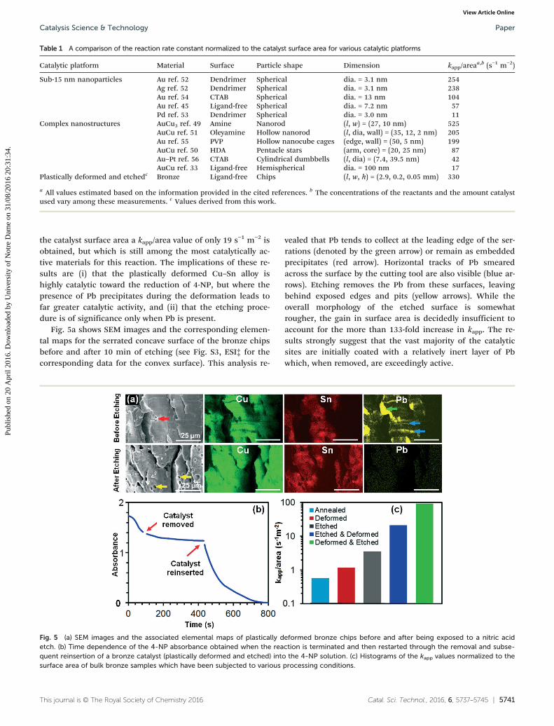
Fig. 5a shows SEM images and the corresponding elemen-tal maps for the serrated concave surface of the bronze chipsbefore and after 10 min of etching (see Fig. S3, ESI‡ for thecorresponding data for the convex surface). This analysis re-
vealed that Pb tends to collect at the leading edge of the ser-rations (denoted by the green arrow) or remain as embeddedprecipitates (red arrow). Horizontal tracks of Pb smearedacross the surface by the cutting tool are also visible (blue ar-rows). Etching removes the Pb from these surfaces, leavingbehind exposed edges and pits (yellow arrows). While theoverall morphology of the etched surface is somewhatrougher, the gain in surface area is decidedly insufficient toaccount for the more than 133-fold increase in kapp. The re-sults strongly suggest that the vast majority of the catalyticsites are initially coated with a relatively inert layer of Pbwhich, when removed, are exceedingly active.
Table 1 A comparison of the reaction rate constant normalized to the catalyst surface area for various catalytic platforms
Catalytic platform Material Surface Particle shape Dimension kapp/areaa,b (s−1 m−2)
Sub-15 nm nanoparticles Au ref. 52 Dendrimer Spherical dia. = 3.1 nm 254Ag ref. 52 Dendrimer Spherical dia. = 3.1 nm 238Au ref. 54 CTAB Spherical dia. = 13 nm 104Au ref. 45 Ligand-free Spherical dia. = 7.2 nm 57Pd ref. 53 Dendrimer Spherical dia. = 3.0 nm 11
Complex nanostructures AuCu3 ref. 49 Amine Nanorod (l, w) = (27, 10 nm) 525AuCu ref. 51 Oleyamine Hollow nanorod (l, dia, wall) = (35, 12, 2 nm) 205Au ref. 55 PVP Hollow nanocube cages (edge, wall) = (50, 5 nm) 199AuCu ref. 50 HDA Pentacle stars (arm, core) = (20, 25 nm) 87Au–Pt ref. 56 CTAB Cylindrical dumbbells (l, dia) = (7.4, 39.5 nm) 42AuCu ref. 33 Ligand-free Hemispherical dia. = 100 nm 17
Plastically deformed and etchedc Bronze Ligand-free Chips (l, w, h) = (2.9, 0.2, 0.05 mm) 330
a All values estimated based on the information provided in the cited references. b The concentrations of the reactants and the amount catalystused vary among these measurements. c Values derived from this work.
Fig. 5 (a) SEM images and the associated elemental maps of plastically deformed bronze chips before and after being exposed to a nitric acidetch. (b) Time dependence of the 4-NP absorbance obtained when the reaction is terminated and then restarted through the removal and subse-quent reinsertion of a bronze catalyst (plastically deformed and etched) into the 4-NP solution. (c) Histograms of the kapp values normalized to thesurface area of bulk bronze samples which have been subjected to various processing conditions.
Catalysis Science & Technology Paper
Publ
ishe
d on
20
Apr
il 20
16. D
ownl
oade
d by
Uni
vers
ity o
f N
otre
Dam
e on
31/
08/2
016
20:3
1:34
. View Article Online
5742 | Catal. Sci. Technol., 2016, 6, 5737–5745 This journal is © The Royal Society of Chemistry 2016
Further mechanistic insights were obtained by preparingidentical bulk bronze samples (7 × 7 × 1.5 mm3) which couldthen be subjected to plastic deformations and etching pro-cesses. In all cases, the samples were first annealed at 300 °Cto limit any catalytic activity associated with the initial sam-ple preparation. When plastic deformation was carried out, itwas through a bending deformation. These bulk samplesallowed for easy removal from the cuvette midway throughthe reaction followed by reinsertion at a later time. Fig. 5bshows the time-dependent absorbance of a bronze catalyst asthis procedure is carried out. The fact that the reaction termi-nates when the catalyst is removed confirms that it is thebronze surface, and not leached material, which is catalytic.The influence of processing conditions on the reaction rateconstant is summarized by the histogram shown in Fig. 4c.Note that the wide variation in the kapp/area values necessi-tate the use of a logarithmic scale. The annealed sample is,as expected, a relatively poor catalyst. Moderate increases areexperienced when samples are either etched or bent, but notboth. The combination of etching and bending, however,gives rise to dramatic increases in kapp where a bending-etching process shows a more than 4-fold enhancement overthe reverse etching-bending sequence. The results supportthe conclusion that the formation and/or activity of the cata-lytic sites is enhanced, not solely through etching, but whenthe immiscible Pb precipitates are present within the Cu–Snalloy during plastic deformation.
Mechanistic drivers for the catalytic activity
The assembled results point toward three factors of signifi-cance when forming highly catalytic Cu–Sn surfaces: (i) plas-tic deformation, (ii) the presence of Pb precipitates withinthe alloy matrix, and (iii) the etching procedure. While acomprehensive mechanistic understanding is unattainablefrom this initial study, it is possible to speculate on the rolesplayed by each these three factors. With all of the materialsstudied showing increased catalytic activity toward the reduc-tion of 4-NP, it has been unequivocally demonstrated thatplastic deformation leads to the formation of active sites.This activity likely stems from the deformation-induced sur-face reconstruction which gives rise to a disorganized nano-textured surface with a high density of steps, kinks, andundercoordinated atoms. Such features are widely acknowl-edged as being conducive to catalytic activity. While most ofthe energy used in the deformation process is dissipated asheat (>90%),16 the retention of strain energy within the crys-tal lattice could also contribute to the catalytic activity.21–27
With plastically deformed elemental Pb showing no cata-lytic activity toward the reduction of 4-NP (see Fig. S5a, ESI‡),it is not surprising that its removal through etching leads toa more catalytic surface. This, however, does not account forthe more than one order of magnitude difference in kapp be-tween etched bronze and its Pb-free counterpart (Fig. 4c–f).This dissimilarity likely originates from the fact that the de-formation process is fundamentally altered when Pb-
precipitates are present in the alloy matrix; their impact onthe shear deformation process (i.e., their machinability) is, infact, the reason they are added to this particular alloy.44 Suchdifferences could direct the deformation process toward asurface which is more active. Precipitates within an alloy ma-trix also tend to act as impediments to edge dislocation mo-tion. With the resulting dislocation pile-up at the precipitateboundary giving rise to significant lattice strains, it is con-ceivable that such strains may be conducive to the formationof catalytic sites.
While the role of the etching procedure may simply be toremove catalytically inactive Pb from the surface, it is difficultto rule out other possibilities. Etching procedures, specificallythose which preferentially remove one component of an alloy(i.e., dealloying), are well-established as a means to promotecatalytically activity.2–9 The etching procedure used, while re-moving Pb from the surface, also leads to the loss of Cu as isevident from a color change in the etching solution which be-gins after 2½ min and transforms it from transparent to thecharacteristic blue color associated with solvated Cu2+ ions.In addition, when much longer etching times than thoseused to produce the Cu–Sn catalyst are carried out (>60min), the surface appears Sn-rich. While such factors pointtoward dealloying as a mechanistic driver of significance,there are arguments to be made against this possibility. Fore-most, is the fact that the Pb-free bronze shows little improve-ment in kapp after it has undergone the same etching proce-dure (before: 5 × 10⁻³ s−1, after: 6 × 10⁻³ s−1) even though itshould experience similar levels of dealloying. The fact thatplastically deformed elemental Sn, by itself, shows essentiallyno catalytic activity toward the reduction of 4-NP (see Fig.S5b, ESI‡) further argues against this possibility. It is alsonoted that the 10 min etch times and acid concentrationsused to activate the Cu–Sn catalyst are much smaller thanthose typically used when dealloying materials. In addition,the highly porous morphologies expressed by dealloyedmaterials2–9 do not resemble those of the etched catalyst(Fig. 5a). Nevertheless, it is impossible at this stage to ruleout etching-induced surface alterations as a means to gener-ate catalytically active sites, a scenario whose likelihood be-comes more probable if the sites are formed through syner-gistic processes requiring the exposure of a strained surfaceto an etchant. Such synergies may, in fact, be partially re-sponsible for the high catalytic activity displayed by nano-porous Au since the dealloying process is accompanied by aspontaneous plastic deformation.39–42
Conclusion
In summary, we have demonstrated that the plastic deforma-tion of a Cu–Sn alloy with Pb precipitates followed by anetching procedure renders its surface highly catalytic towardthe reduction of 4-NP. Such surfaces compare favorably tothe top performing nanoscale catalysts when benchmarkedusing the reaction rate constant normalized to the surfacearea of the catalyst. The catalysts are easily fabricated and are
Catalysis Science & TechnologyPaper
Publ
ishe
d on
20
Apr
il 20
16. D
ownl
oade
d by
Uni
vers
ity o
f N
otre
Dam
e on
31/
08/2
016
20:3
1:34
. View Article Online
Catal. Sci. Technol., 2016, 6, 5737–5745 | 5743This journal is © The Royal Society of Chemistry 2016
demonstrated as inexpensive, robust, highly recyclable, andamenable to continuous-flow catalytic reactions. The resultsstrongly suggest that the presence of Pb precipitates withinthe Cu–Sn alloy matrix during the deformation is highly con-ducive to the formation of catalytically active sites. Theseplastically deformed surfaces join a class of bulk-scale mate-rials such as dealloyed metals, RANEY® catalysts, and varioussponge-like materials, where catalysis occurs on disorganizedsurfaces with a high density of steps, kinks, andundercoordinated atoms. The work opens up the possibilityof using similarly formed catalytic materials in a broad rangeof reactions driven by the alloy combination deemed mosteffective.
ExperimentalChemicals and materials
(111)-, (110)-, and (100)-oriented single crystals of Cu with apurity greater than 99.99% were purchased from MTI Corp.The crystals, which have dimensions of 10 × 10 × 0.5 mm, areone-side polished with an RMS roughness of less than 30 Å.The catalytic materials were derived from solid rods of C110copper, C353 brass (Cu : Zn : Pb = 61.5 : 36.5 : 2 wt%), C936bronze (Cu : Sn : Pb = 81 : 7 : 12 wt%) and C510 bronze (Cu :Sn : P = 94.8 : 5 : 0.2 wt%) with a diameter of 2.54 cm. Catalystetching procedures utilized nitric acid (Sigma Aldrich).Annealing regimens were carried out in ultra-high purity(UHP) Ar. Solutions for catalysis were prepared using 4-NP(Fluka), NaBH4 (Fluka), and deionized (DI) water derivedfrom a Milli-Q system (18.2 MΩ cm at 25 °C).
Sample preparation through plastic deformation and etching
The plastic deformation of single crystals of copper. Priorto use as a catalyst, both the unpolished and side surfaces ofthe single crystals were coated with a lacquer in order to ren-der these surfaces catalytically inactive. All catalytic activitycould, hence, be attributed to the single exposed polishedsurface (see Fig. S4, ESI‡). The bending deformation arounda nylon surface with a radius of curvature of 2 cm was carriedout using bending pliers. After deformation a second layer oflacquer was applied in order to ensure that the unpolishedand side surfaces remained catalytically inactive.
The fabrication of plastically deformed metal chips of cop-per, bronze, and brass. The metal chips of copper, bronze,and brass which were used as catalysts in the fixed-bed con-tinuous-flow reactor (Fig. 3a) were formed using the shearingforces which a tungsten carbide cutting tool exerted on a ro-tating metal rod. The parameters used in the shearing pro-cess were optimized for each metal (see Table S1, ESI‡) toyield the maximum catalytic activity using 100 mg samplesizes. Etching procedures were carried out in 2 M nitric acidunder gentle stirring followed by a thorough rinse in DIwater.
The fabrication of bulk bronze samples for mechanisticstudies. The bulk bronze catalysts, with dimensions of 7 × 7 ×1.5 mm3, which were used to generate the data in Fig. 5b and c
were all cut from the same metal rod used to fabricate themetal chips for the fixed-bed reactor. Once cut, the surfaceswere polished and annealed in order to minimize any cata-lytic activity stemming from the cutting process. Theannealing regimen saw the samples heated to 300 °C for 2 hin a tube furnace where Ar was flowed at a rate of 60 sccm.
Catalysis measurements
Catalysis on Cu single crystals and bulk bronze samples.All absorbance spectra were obtained for reactions carriedout in a 1 cm path length quartz cuvette containing a 2 mLaqueous solution of the 4-NP (100 μM) and NaBH4 (10 mM)reactants. The surface area of the 100 mg bronze sample,form which the kapp/area values were obtained, was estimatedfrom SEM measurements on 20 bronze chips of knownweight. The estimate was conservative in that the calculationaccounted for the surface roughness by assuming that eachstriation penetrated through the through the entire thicknessof the chip even though this exaggerated the result. No allow-ances were made for the fact that a substantial portion of thecatalyst surface area is resting on the bottom cuvette and is,hence, shielded from the 4-NP solution.
Catalysis using the fixed-bed catalytic reactor. The appara-tus used to demonstrate continuous flow catalysis was inten-tionally designed to mimic that used by He et al.40 in orderto facilitate comparisons with the many impressive bench-marks set when using Au nanorod catalysts affixed to glass fi-ber supports. The copper, bronze, and brass catalysts were alltested in the same apparatus, but where an emptied columnwas first cleaned by filling it with 150 mM nitric acid for atleast 24 hours before switching materials. The column wasthen thoroughly flushed with DI water before adding the newcatalyst. It was then filled to height of 8.5 cm with the cata-lyst material. Whenever fresh catalytic material was used, theproduct exiting from the reactor initially appeared discolored(grey to black), but then quickly turned clear. To circumventthese contamination issues, a conditioning process wasadopted whereby fresh catalytic material was exposed to a200 mL aqueous solution of 10 mM 4-NP and 1 mM NaBH4
prior to collecting any data.Once the conditioning process was complete, the reactor
was optimized by trying to reduce the highest possible 4-NPconcentration at the highest flow rate. For these experiments,the 4-NP concentration was increased in 5 mM increments toa maximum of 30 mM, where the 4-NP :NaBH4 molar ratiowas held constant at 1 : 100, a value which is typical for thisreaction. Spectroscopic characterization of the reactants andproduct obtained were carried out in order to determine the4-NP percent conversion (Fig. 3b and c). Prior to analysis the4-NP and 4-AP concentrations were diluted by a factor of 300and 100, respectively, in order to allow detectable levels oflight to pass through the sample. Such dilutions are requiredbecause the concentrations used in the reactor are more than100× greater than that which is typically used for a spectro-scopic assessment of catalysts for the reduction of 4-NP.
Catalysis Science & Technology Paper
Publ
ishe
d on
20
Apr
il 20
16. D
ownl
oade
d by
Uni
vers
ity o
f N
otre
Dam
e on
31/
08/2
016
20:3
1:34
. View Article Online
5744 | Catal. Sci. Technol., 2016, 6, 5737–5745 This journal is © The Royal Society of Chemistry 2016
The fixed-bed reactor was operated for a 7 day period foreach of the catalysts assessed (i.e., copper, brass, andbronze), whereby 100 mL of reactants were flowed at the max-imum sustainable rate at least once per day. Between teststhe column was filled with the 4-AP product since the long-term exposure of the drying catalysts to air led to a discolor-ation and diminished catalytic activity. The reactor was alsooperated with suction applied at the output in order to dem-onstrate the faster flow rates achievable when using the plas-tically deformed and etched bronze catalyst. High flow ratesare facilitated by the greater pressure differential created be-tween the input and output of the reactor.
ICP-MS measurements
The 4-AP product derived from the fixed-bed catalytic reactorwas analyzed for Cu, Sn, and Pb using ICP-MS. The samplesused were acquired after, at least, 300 mL of reactants hadbeen flowed through the fixed-bed reactor. They were then di-luted by a factor of 100 with DI water. The test tubes for ICP-MS analysis were three times acid washed with 150 mMHNO3 and 5 times rinsed with DI water. Metal analysis wasconducted on acidified samples (1% HNO3) using an Agilent7900 inductively coupled plasma mass spectrometer (ICP-MS).Before each use, the instrument was tuned to minimize oxidesand double charged ions; He gas was included in the collisioncell to minimize polyatomic interferences. Samples were di-luted as needed to ensure accurate analysis and internal stan-dards were employed to account for matrix effects. Triplicatesamples were analyzed for each treatment and reproducibilitywas high among replicates. Cu and Sn were monitored atmultiple mass peaks, and data is presented from the masswith the least interference. Presented Pb concentrations arethe summation of three isotopes (206, 207, and 208). Detec-tion limits were analyte and run specific, but were generallyless than 1 μg L−1.
Instrumentation
SEM images and EDS elemental maps were obtained using a450 FEG ESEM environmental scanning electron microscopein secondary electron mode. The spectroscopic assessment ofcatalytic processes was carried out using a Jasco UV/VisSpectrophotometer V630. An Agilent 7900 ICP-MS was usedto determine the levels of Cu, Sn, and Pb in the 4-AP product.Annealing procedures were carried out in a Lindberg Blue Mfurnace equipped with a quartz tube and the fittings neededto maintain a continuous flow of UHP Ar gas.
Acknowledgements
This work is funded by the National Science Foundationawards (DMR-1053416 and DMR-1505114) to S. Neretina. Ithas also benefited from the facilities available through Tem-ple University's Nano Instrumentation Center as well as theexpertise of D. A. Dikin (Facility Manager). K. D. G. acknowl-edges helpful discussions with Dr. Eric Borguet (Chemistry,
Temple University) and support received through a TempleUniversity Graduate Student Fellowship.
References
1 E. Roduner, Chem. Soc. Rev., 2006, 35, 583–592.2 J. Biener, M. M. Biener, R. J. Madix and C. M. Friend, ACS
Catal., 2015, 5, 6263–6270.3 X. Zhang and Y. Ding, Catal. Sci. Technol., 2013, 3,
2862–2868.4 A. Wittstock and M. Bäumer, Acc. Chem. Res., 2014, 47,
731–739.5 L.-C. Wang, K. J. Stowers, B. Zugic, M. M. Biener, J. Biener,
C. M. Friend and R. J. Madix, Catal. Sci. Technol., 2015, 5,1299–1306.
6 T. Fujita, P. Guan, K. McKenna, X. Lang, A. Hirata, L. Zhang,T. Tokunaga, S. Arai, Y. Yamamoto, N. Tanaka, Y. Ishikawa,N. Asao, Y. Yamamoto, J. Erlebacher and M. Chen, Nat.Mater., 2012, 11, 775–780.
7 A. Wittstock, V. Zielasek, J. Biener, C. M. Friend and M.Bäumer, Science, 2010, 327, 319–322.
8 C. Xu, J. Su, X. Xu, P. Liu, H. Zhao, F. Tian and Y. Ding,J. Am. Chem. Soc., 2007, 129, 42–43.
9 V. Zielasek, B. Jürgens, C. Schulz, J. Biener, M. M. Biener,A. V. Hamza and M. Bäumer, Angew. Chem., Int. Ed.,2006, 45, 8241–8244.
10 J. Rosen, G. S. Hutchings, Q. Lu, S. Rivera, Y. Zhou, D. G.Vlachos and F. Jiao, ACS Catal., 2015, 5, 4293–4299.
11 Q. Lu, J. Rosen, Y. Zhou, J. S. Hutchings, Y. C. Kimmel, J. G.Chen and F. Jiao, Nat. Commun., 2014, 5, 3242.
12 J. R. Mellor, N. J. Coville, S. H. Durbach and R. G.Copperthwaite, Appl. Catal., A, 1998, 171, 273–281.
13 P. Zhao, X. Feng, D. Huang, G. Yang and D. Astruc, Coord.Chem. Rev., 2015, 287, 114–136.
14 P. Hervés, M. Pérez-Lorenzo, L. M. Liz-Marzán, J. Dzubiella,Y. Lu and M. Ballauff, Chem. Soc. Rev., 2012, 41, 5577–5587.
15 Y. Z. Dai and F. P. Chiang, J. Eng. Mater. Technol., 1992, 114,432–438.
16 R. Abbaschian, L. Abbaschian and R. E. Reed-Hill, PhysicalMetallurgy Principles, Cengage Learning, Stamford, 2009.
17 M. Gsell, P. Jakob and D. Menzel, Science, 1998, 280,717–720.
18 Z. Li, D. V. Potapenko and R. M. Osgood, ACS Nano, 2015, 9,82–87.
19 P. G. Fox, J. Mater. Sci., 1975, 10, 340–360.20 R. Otero, F. Calleja, V. M. García-Suárez, J. J. Hinarejos, J. de
la Figuera, J. Ferrer, A. L. Váquez de Parga and R. Miranda,Surf. Sci., 2004, 550, 65–72.
21 M. F. Francis and W. A. Curtin, Nat. Commun., 2015, 6, 6261.22 P. Strasser, S. Koh, T. Anniyev, J. Greeley, K. More, C. F. Yu,
Z. C. Liu, S. Kaya, D. Nordlund, H. Ogasawara, M. F. Toneyand A. Nilsson, Nat. Chem., 2010, 2, 454–460.
23 A. Jha, D.-W. Jeong, J.-O. Shim, W.-J. Jang, Y.-L. Lee, C. V.Rode and H.-S. Roh, Catal. Sci. Technol., 2015, 5, 2752–2760.
24 L. Gan, M. Heggen, S. Rudi and P. Strasser, Nano Lett.,2012, 12, 5423–5430.
Catalysis Science & TechnologyPaper
Publ
ishe
d on
20
Apr
il 20
16. D
ownl
oade
d by
Uni
vers
ity o
f N
otre
Dam
e on
31/
08/2
016
20:3
1:34
. View Article Online

Catal. Sci. Technol., 2016, 6, 5737–5745 | 5745This journal is © The Royal Society of Chemistry 2016
25 S. Zhang, X. Zhang, G. Jiang, H. Zhu, S. Guo, D. Su, G. Luand S. Sun, J. Am. Chem. Soc., 2014, 136, 7734–7739.
26 J. X. Wang, H. Inada, L. Wu, Y. Zhu, Y. Choi, P. Liu, W.-P.Zhou and R. R. Adzic, J. Am. Chem. Soc., 2009, 131,17298–17302.
27 M. Mavrikakis, B. Hammer and J. K. Nørskov, Phys. Rev.Lett., 1998, 81, 2819–2822.
28 J. K. Nørskov, T. Bligaard, B. Hvolbæk, F. Abild-Pederson, I.Chorkendorff and C. H. Christensen, Chem. Soc. Rev.,2008, 37, 2163–2171.
29 B.-N. D. Ngô, A. Stukowski, N. Mameka, J. Markmann, K.Albe and J. Weissmüller, Acta Mater., 2015, 93, 144–155.
30 J. Weissmüller, H.-L. Duan and D. Farkas, Acta Mater.,2010, 58, 1–13.
31 J. Weissmüller, R. C. Newman, H.-J. Jin, A. M. Hodge andJ. W. Kysar, MRS Bull., 2009, 34, 577–586.
32 S. Parida, D. Kramer, C. A. Volkert, H. Rösner, J. Erlebacherand J. Weissmüller, Phys. Rev. Lett., 2006, 97, 035504.
33 M. Hajfathalian, K. D. Gilroy, A. Yaghoubzade, A. Sundar, T.Tan, R. A. Hughes and S. Neretina, J. Phys. Chem. C,2015, 119, 17308–17315.
34 E. Hariprasad and T. P. Radhakrishnan, Chem. Eur. – J.,2010, 16, 14378–14384.
35 G. Zheng, L. Polavarapu, L. M. Liz-Marzán, I. Pastoriza-Santos and J. Pérez-Juste, Chem. Commun., 2015, 51,4572–4575.
36 A. Verdaguer-Casadevall, C. W. Li, T. P. Johansson, S. B.Scott, J. T. McKeown, M. Kumar, I. E. L. Stephens, M. W.Kanan and I. Chorkendorff, J. Am. Chem. Soc., 2015, 137,9808–9811.
37 X. Feng, K. Jiang, S. Fan and M. W. Kanan, J. Am. Chem.Soc., 2015, 137, 4606–4609.
38 C. W. Li, J. Ciston and M. W. Kanan, Nature, 2014, 508,504–507.
39 L. E. Cratty, Jr. and A. V. Granato, J. Chem. Phys., 1957, 26,96–97.
40 J. He, W. Ji., L. Yao, Y. Wang, B. Khezri, R. D. Webster andH. Chen, Adv. Mater., 2014, 26, 4151–4155.
41 H.-W. Liang, W.-J. Zhang, Y.-N. Ma, X. Cao, Q.-F. Guan,W.-P. Xu and S.-H. Yu, ACS Nano, 2011, 5, 8148–8161.
42 D. M. Dotzauer, J. Dai, L. Sun and M. L. Bruening, NanoLett., 2006, 6, 2268–2272.
43 R. Ricciardi, J. Huskens and W. Verboom, ChemSusChem,2015, 8, 2586–2605.
44 K. Kato and K. Adachi, Modern Tribology Handbook, vol. 1,CRC Press LLC, London, 2001.
45 S. Gu, J. Kaiser, G. Marzun, A. Ott, Y. Lu, M. Ballauff, A.Zaccone, S. Barcikowski and P. Wagener, Catal. Lett.,2015, 145, 1105–1112.
46 S. V. Jenkins, S. Chen and J. Chen, Tetrahedron Lett.,2015, 56, 3368–3372.
47 M. M. Nigra, J.-M. Ha and A. Katz, Catal. Sci. Technol.,2013, 3, 2976–2983.
48 S. Wunder, Y. Lu, M. Albrecht and M. Ballauff, ACS Catal.,2011, 1, 908–916.
49 S. Chen, S. V. Jenkins, J. Tao, Y. Zhu and J. Chen, J. Phys.Chem. C, 2013, 117, 8924–8932.
50 R. He, Y.-C. Wang, X. Wang, Z. Wang, G. Liu, W. Zhou, L.Wen, Q. Li, X. Wang, X. Chen, J. Zeng and J. G. Hou, Nat.Commun., 2014, 5, 4327.
51 S. Thota, S. Chen and J. Zhao, Chem. Commun., 2016, 52,5593.
52 M. Nemanashi and R. Meijboom, J. Colloid Interface Sci.,2013, 389, 260–267.
53 C. Deraedt, L. Salmon and D. Astruc, Adv. Synth. Catal.,2014, 356, 2525–2538.
54 R. Fenger, E. Fertitta, H. Kirmse, A. F. Thünumann and K.Rademann, Phys. Chem. Chem. Phys., 2012, 14, 9343–9349.
55 J. Zeng, Q. Zhang, J. Chen and Y. Xia, Nano Lett., 2010, 10,30–35.
56 Y. Lu, J. Yuan, F. Polzer, M. Drechsler and J. Preussner, ACSNano, 2010, 4, 7078–7086.
Catalysis Science & Technology Paper
Publ
ishe
d on
20
Apr
il 20
16. D
ownl
oade
d by
Uni
vers
ity o
f N
otre
Dam
e on
31/
08/2
016
20:3
1:34
. View Article Online