catch the bug - teachergeek.org
TRANSCRIPT
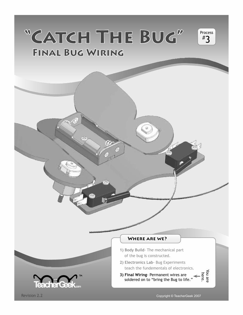
Final Bug Wiring
Copyright © TeacherGeek 2007 Revision 2.2
™
Process#3
Where are we ?
1) Body Build- The mechanical part of the bug is constructed.
2) Electronics Lab- Bug Experiments teach the fundementals of electronics.
3) Final Wiring- Permanent wires are soldered on to “bring the Bug to life.”
You are here.
“Catch The Bug”
Copyright © TeacherGeek 2007
Final Wiring Page 2
™
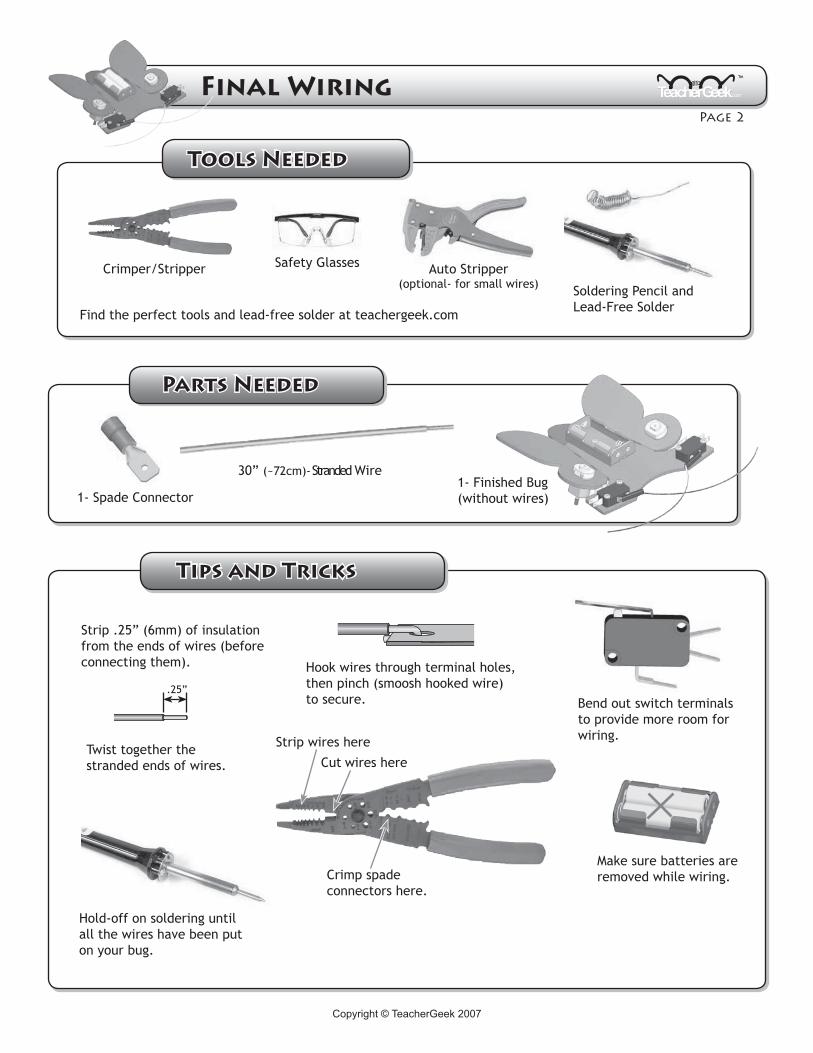
Find the perfect tools and lead-free solder at teachergeek.com
Crimper/Stripper
Soldering Pencil and Lead-Free Solder
Tools Needed
1- Spade Connector
30” (~72cm)- Stranded Wire
Auto Stripper(optional- for small wires)
Safety Glasses
1- Finished Bug(without wires)
Tips and Tricks
Hold-off on soldering until all the wires have been put on your bug.
Make sure batteries are removed while wiring.
Hook wires through terminal holes, then pinch (smoosh hooked wire) to secure. Bend out switch terminals
to provide more room for wiring.
Strip .25” (6mm) of insulation from the ends of wires (before connecting them).
Twist together the stranded ends of wires.
Crimp spade connectors here.
Strip wires here
Cut wires here
.25”
Parts Needed
Copyright © TeacherGeek 2007 Copyright © TeacherGeek 2007
Final Wiring Page �
™
M
M
Switch Harness
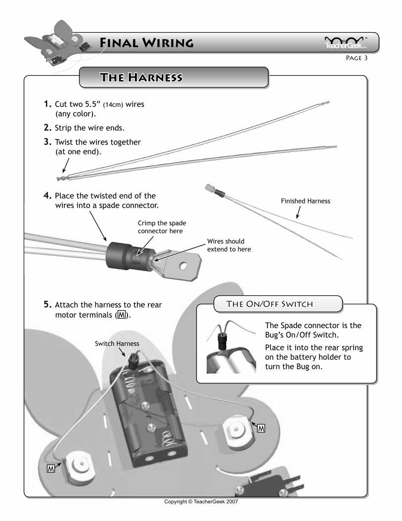
1. Cut two 5.5” (14cm) wires (any color).
2. Strip the wire ends.
3. Twist the wires together (at one end).
4. Place the twisted end of the wires into a spade connector.
5. Attach the harness to the rear motor terminals ( M ).
Crimp the spade connector here
Wires should extend to here
Finished Harness
The Spade connector is the Bug’s On/Off Switch.
Place it into the rear spring on the battery holder to turn the Bug on.
The Harness
The On/Off Switch
Copyright © TeacherGeek 2007
Final Wiring Page �
™
Copyright © TeacherGeek 2007
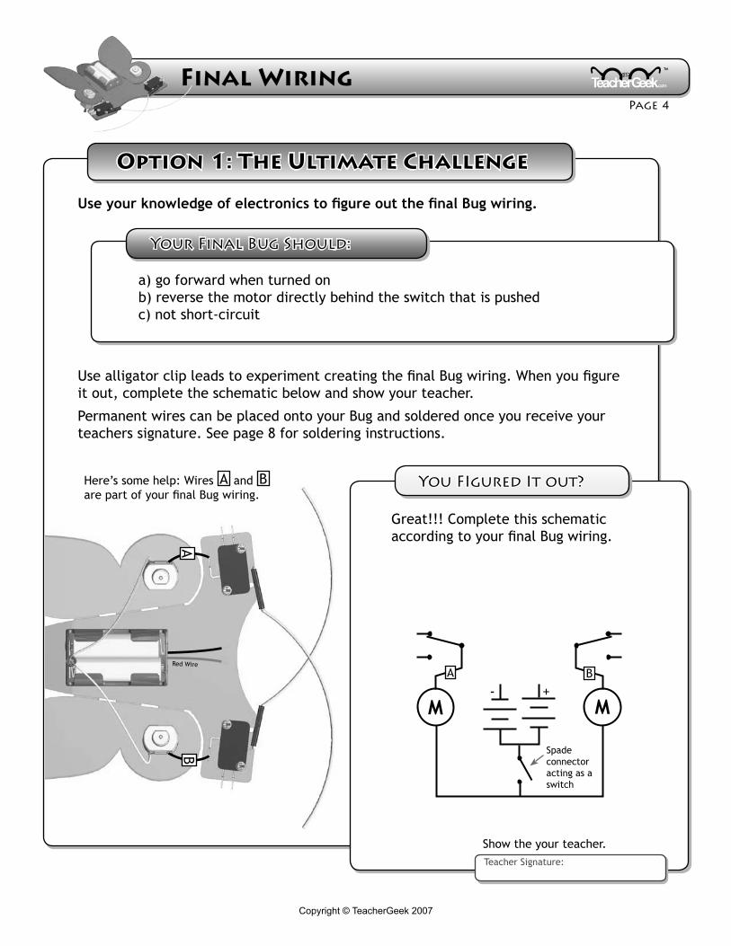
Option 1: The Ultimate Challenge
Use your knowledge of electronics to figure out the final Bug wiring.
Red Wire
BA
Here’s some help: Wires A and B are part of your final Bug wiring.
MM+-
BA
Spade connector acting as a switch
Great!!! Complete this schematic according to your final Bug wiring.
Show the your teacher.Teacher Signature:
a) go forward when turned on b) reverse the motor directly behind the switch that is pushedc) not short-circuit
Use alligator clip leads to experiment creating the final Bug wiring. When you figure it out, complete the schematic below and show your teacher.
Permanent wires can be placed onto your Bug and soldered once you receive your teachers signature. See page 8 for soldering instructions.
You FIgured It out?
Your Final Bug Should:
Copyright © TeacherGeek 2007 Copyright © TeacherGeek 2007
Final Wiring Page �
™
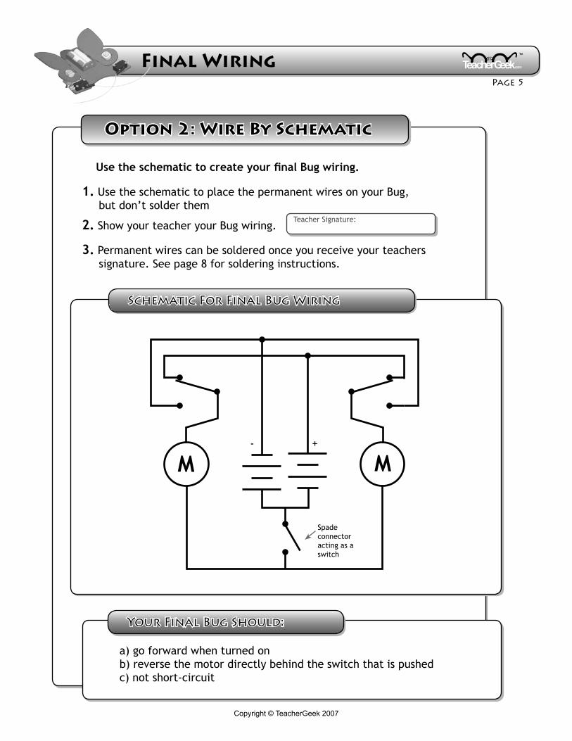
Option 2: Wire By Schematic
Schematic For Final Bug Wiring
MM+-
Spade connector acting as a switch
Teacher Signature:
Use the schematic to create your final Bug wiring.
1. Use the schematic to place the permanent wires on your Bug, but don’t solder them
2. Show your teacher your Bug wiring.
3. Permanent wires can be soldered once you receive your teachers signature. See page 8 for soldering instructions.
a) go forward when turned on b) reverse the motor directly behind the switch that is pushedc) not short-circuit
Your Final Bug Should:
Copyright © TeacherGeek 2007
Final Wiring Page �
™
Copyright © TeacherGeek 2007
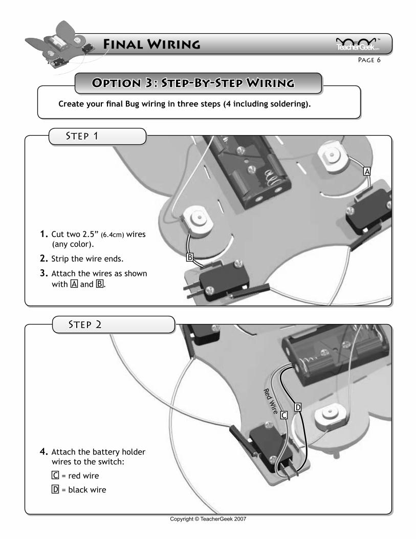
Create your final Bug wiring in three steps (4 including soldering).
A
B
CD
1. Cut two 2.5” (6.4cm) wires (any color).
2. Strip the wire ends.
3. Attach the wires as shown with A and B .
4. Attach the battery holder wires to the switch:
C = red wire
D = black wire
Red Wire
Option 3: Step-By-Step Wiring
Step 1
Step �
Copyright © TeacherGeek 2007 Copyright © TeacherGeek 2007
Final Wiring Page �
™
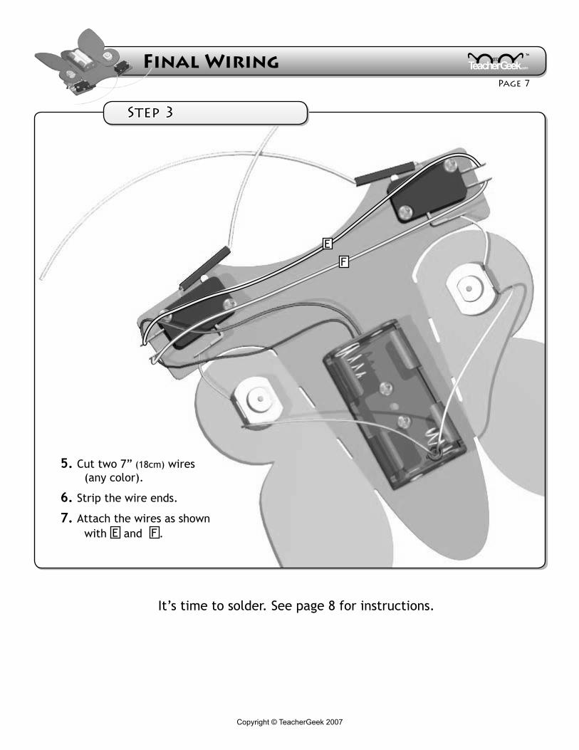
E
F
5. Cut two 7” (18cm) wires (any color).
6. Strip the wire ends.
7. Attach the wires as shown with E and F .
It’s time to solder. See page 8 for instructions.
Step �
Copyright © TeacherGeek 2007
Final Wiring Page �
™
Copyright © TeacherGeek 2007
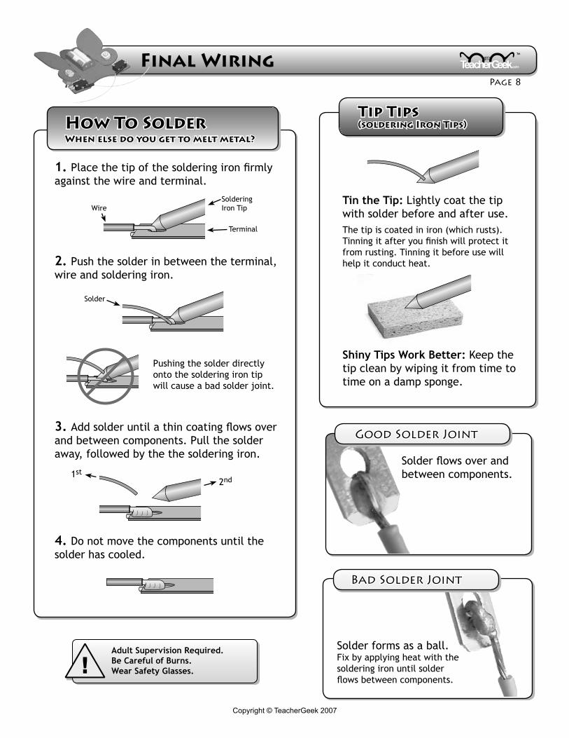
Tin the Tip: Lightly coat the tip with solder before and after use.The tip is coated in iron (which rusts). Tinning it after you finish will protect it from rusting. Tinning it before use will help it conduct heat.
Shiny Tips Work Better: Keep the tip clean by wiping it from time to time on a damp sponge.
!Adult Supervision Required. Be Careful of Burns.Wear Safety Glasses.
Pushing the solder directly onto the soldering iron tip will cause a bad solder joint.
Soldering Iron TipWire
Terminal
Solder
How To SolderWhen else do you get to melt metal?
Good Solder Joint
Bad Solder Joint
Solder forms as a ball. Fix by applying heat with the soldering iron until solder flows between components.
Solder flows over and between components.
Tip Tips (soldering Iron Tips)
1st2nd
1. Place the tip of the soldering iron firmly against the wire and terminal.
2. Push the solder in between the terminal, wire and soldering iron.
3. Add solder until a thin coating flows over and between components. Pull the solder away, followed by the the soldering iron.
4. Do not move the components until the solder has cooled.
Copyright © TeacherGeek 2007 Copyright © TeacherGeek 2007
Final Wiring Page �
™
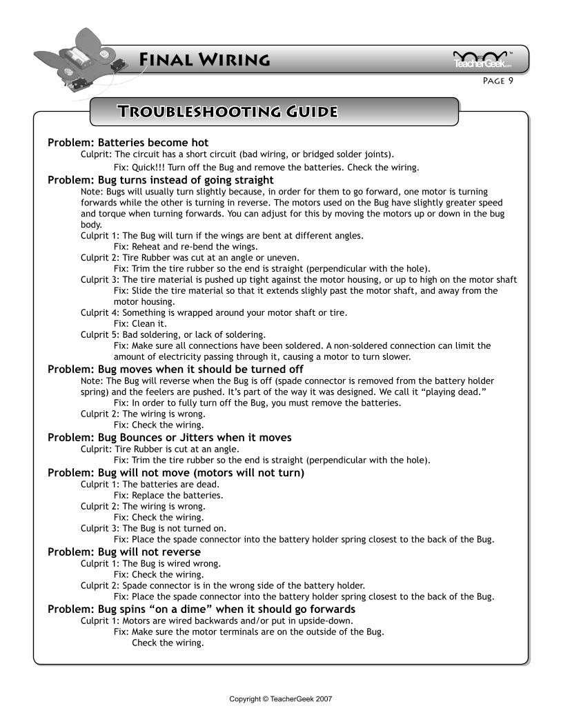
Troubleshooting Guide
Problem: Batteries become hot Culprit: The circuit has a short circuit (bad wiring, or bridged solder joints). Fix: Quick!!! Turn off the Bug and remove the batteries. Check the wiring.Problem: Bug turns instead of going straight Note: Bugs will usually turn slightly because, in order for them to go forward, one motor is turning forwards while the other is turning in reverse. The motors used on the Bug have slightly greater speed and torque when turning forwards. You can adjust for this by moving the motors up or down in the bug body. Culprit 1: The Bug will turn if the wings are bent at different angles. Fix: Reheat and re-bend the wings. Culprit 2: Tire Rubber was cut at an angle or uneven. Fix: Trim the tire rubber so the end is straight (perpendicular with the hole). Culprit 3: The tire material is pushed up tight against the motor housing, or up to high on the motor shaft Fix: Slide the tire material so that it extends slighly past the motor shaft, and away from the motor housing. Culprit 4: Something is wrapped around your motor shaft or tire. Fix: Clean it. Culprit 5: Bad soldering, or lack of soldering. Fix: Make sure all connections have been soldered. A non-soldered connection can limit the amount of electricity passing through it, causing a motor to turn slower. Problem: Bug moves when it should be turned off Note: The Bug will reverse when the Bug is off (spade connector is removed from the battery holder spring) and the feelers are pushed. It’s part of the way it was designed. We call it “playing dead.” Fix: In order to fully turn off the Bug, you must remove the batteries. Culprit 2: The wiring is wrong. Fix: Check the wiring.Problem: Bug Bounces or Jitters when it moves Culprit: Tire Rubber is cut at an angle. Fix: Trim the tire rubber so the end is straight (perpendicular with the hole).Problem: Bug will not move (motors will not turn) Culprit 1: The batteries are dead. Fix: Replace the batteries. Culprit 2: The wiring is wrong. Fix: Check the wiring. Culprit 3: The Bug is not turned on. Fix: Place the spade connector into the battery holder spring closest to the back of the Bug.Problem: Bug will not reverse Culprit 1: The Bug is wired wrong. Fix: Check the wiring. Culprit 2: Spade connector is in the wrong side of the battery holder. Fix: Place the spade connector into the battery holder spring closest to the back of the Bug.Problem: Bug spins “on a dime” when it should go forwards Culprit 1: Motors are wired backwards and/or put in upside-down. Fix: Make sure the motor terminals are on the outside of the Bug. Check the wiring.