cat.e51- b - smc...black white red blue yellow green for special environment tubing collor tubing...
TRANSCRIPT

Pneumatic Piping Equipment
Pn
eum
atic
Pip
ing
Eq
uip
men
t
One-touch FittingsS Coupler
Speed Controller With One-touch FittingsTubing
CAT.E51- B
All specifications in this catalog are subject to change without notice.
Printed in Japan
D-036 1st printing December 2002 D-DAD P-80(DN)
1-16-4 Shimbashi, Minato-ku, Tokyo 105-8659, JAPANTel: 03-3502-2740 Fax: 03-3508-2480URL http://www.smcworld.com©2002 SMC Corporation All Rights Reserved
This catalog is printed on recycled paper with concern for the global environment.

Piping Equipment
Low Speed Control: Elbow / Universal Type
AS1FMP.87
P.88
Dual Speed Controller
ASD30FP.86
Low Speed Control: Inline Type
AS01FMLow Speed Control: Dual Speed Controller
ASD30FM
P.89
P.90
Piping ModuleKB
to
to
P.27
P.31
Rotary One-touch Fittings
KS/KXto
P.20
P.21
Tube Coupler
KCto
P.22
P.24
One-touch Fitting Manifold
KMto
P.25
P.26
One-touch Fittings
KQ2/KQto
P.1
P.13
toP.14
P.19
Miniature One-touch
KJ
Elbow/Universal Type
AS1FInline Type
AS01Fto
P.83
P.84
PolyurethaneTubing
TU
toP.117
P.118to
P.123
P.124Soft
Polyurethane Tubing
TUS
NylonTubing
T
Soft Nylon Tubing
TS
P.85
toP.121
P.122
toP.119
P.120
Related Equipment P.111
KE
Fit
tin
gs
Spee
d Con
trolle
r with
Fittin
gsT
ub
ing
Residual Pressure Exhaust Valve with One-touch Fittings
INDEX1
Piping Equipment
Antistatic Soft Nylon Tubing
TASP.134
FR Double Layer Tubing
TRBto
P.139
P.140
FR Soft Nylon Tubing
TRSto
P.135
P.136
FR Double Layer Polyurethane Tubing
TRBUto
P.137
P.138
Stainless Steel:Dual Speed Controller
ASD30FG P.94Speed Exhaust Controller
ASV0F
Clean Speed Controller
AS21FPto
P.95
P.96
Flame Resistant:Metal Body Elbow Type
AS21-F
Tamper Proof:Dual Speed Controller
ASD30F-T P.106
Flat Head Screw Driver Adjustment:Universal Type
AS1F-DWith Pilot Check Valve
ASP30FP.102
P.101
Tamper Proof:Elbow/Universal Type
AS1F-TTamper Proof:Inline Type
AS01F-T P.105Stainless Steel:Inline Type
AS01FG P.93AS1FE
Self-align Fittings
H,DL,L,LLto
P.72Multi-connector
DMto
P.33
P.34 P.75
S Coupler
KKHto
P.64
P.65Multi-connector with One-touch Fittings
DMKP.35
toP.36
FR One-touch Fitting Manifold
KRMto
P.59
P.60
S Coupler
KKto
P.61
P.63
Antistatic One-touch Fittings
KAto
P.50
P.53
S Coupler
KK13to
P.66
P.67FR One-touch Fittings
KRto
P.54
P.58
Clean One-touch Fittings
KPto
P.44
P.46
Clean One-touch Fittings
KPQ/KPGto
P.47
P.49
Stainless Steel Miniature Fittings
MSto
P.80
P.81
Miniature Fittings
Mto
P.76
Rectangular Multi-connector
KDM
P.79
toP.37
P.43
Insert Fittings
KFto
P.68
P.71
Hard Polyurethane Tubing
TUHP.125
Polyurethane Coil Tubing
TCU P.127
Polyurethane Flat Tubing
TFU
Polyolefin tubing
TPHto
P.129
P.130to
P.126
toP.131
P.132
Stainless Steel:Elbow/Universal Type
AS1FG
Soft Polyolefin Tubing
TPS
P.133Antistatic Polyurethane Tubing
TAU
Related Equipment
Tubing Cutter
TKP.141
Tubing Release Tool
TGP.142
Multiple Tubing Holder
TMP.142
FR Double Layer Tubing Stopper
TKSP.142
Tubing Stand
TBP.141
Tubing Reel
TBRP.141
toP.91
P.92
Flat Head Screw Driver Adjustment:Inline Type
AS01F-D P.109
Flat Head Screw Driver Adjustment:Dual Speed Controller
ASD30F-D
P.32
toP.97
P.98
toP.99
P.100
toP.103
P.104
toP.107
P.108
P.110
P.128
P.112P.112P.111
Multiple Holder
TMAP.111
Check Valve with One-touch Fittings
AKH/AKBQuick Exhaust Valve with Built-in One-touch Fittings
AQ40FP.113 to 115
Energy Saving Valve
ASR/ASQHolder
TMH
Stainless Steel One-touch Fittings
KG
Residual Pressure Exhaust Valve:Elbow/Universal Type
INDEX2

Introduction of Piping Equipment
One-touch Fittings (Black)KQ
Miniature One-touchKJ
Rotary One-touch FittingsKS/KX
One-touch Fitting ManifoldKM
Insert FittingsKF
Miniature FittingsM
One-touch Fittings (White)KQ2
Sleeve
General
KSKX
M3 1/8M5
Mini
Mini
RotationP.1
P.1
P.14
P.76
P.68
P.25
P.20
FittingFitting
Front matter 1

Tubing CouplerKC
Multi-connector with One-touch FittingsDMK
Self-align FittingsH, DL, L, LL
Multi ConnectorDM
Without tubing
With tubing
Sleeve
Soft copper
P.72
P.22
P.33
P.35
Rectangular Multi-connectorKDM P.32
S CouplerKK P.61
S CouplerKKH P.64
S CouplerKK13 P.66
Piping ModuleKB P.27One-touch
attachment and removal
One-touch fitting
Coverring(Super high impact PBT)(High impact PBT)
(Rubber)
Spacer
Sleeve cover
Introduction of Piping Equipment FittingFitting
Front matter 2

Introduction of Piping Equipment
Stainless Miniature FittingsMS
Stainless Steel One-touch FittingsKG
FR One-touch Fitting ManifoldKRM
FR One-touch FittingsKR
Antistatic One-touch FittingsKA
For Special Environment
Flame resistant
Antistatic
SUS303 SUS316P.37
P.50
P.54 P.59
P.80
FittingFitting
Flame resistant Flame resistant
Corrosion Resistant
Spatter Proof
Antistatic Measures
Front matter 3

Clean One-touch FittingsKP
Clean Series: One-touch Fittings10-KQ
Clean Series: Stainless Steel10-KG
Clean Series: Miniature One-touch10-KJ
Clean Series: Rectangular Multi-connector10-KDM
Clean Series: Insert Fittings10-KF
Clean Series: Miniature Fittings10-M•MS
10-M
10-MS
Clean room
For clean blow and washing lines
P.13 P.19 P.43
P.32
P.44Clean One-touch Fittings
KPQ/KPGFor drive system
air piping
P.47
P.79 P.71
Introduction of Piping Equipment FittingFitting
Clean
Front matter 4

Introduction of Piping Equipment
Inline TypeAS•F
Universal TypeAS•F
Dual Speed ControllerASD•F
Elbow/Universal Type AS•FM
Inline TypeAS•FM
Elbow TypeAS•F
Dual Type ASD•FM P.78
General
For Low Speed Operation
Meter in needle
Lurch prevention, Single acting cylinder control
Speed control in the range of 10 to 50 mm/s
Low speed operation of small-bore cylinders
Meter out needle
P.83 P.83
P.85
P.87 P.89 P.90
P.86
Speed ControllerSpeed Controller
Front matter 5

Introduction of Piping Equipment
Clean Speed ControllerAS-FPQ/FPG
Elbow/Universal Type AS•FG
Inline TypeAS•FG
Dual TypeASD•FG
For Special Environment
Clean Series10-AS•F
10-AS•FGeneral
10-ASD•F
10-AS•FM
10-ASD•FM
10-AS•FG
10-ASD•FG
10-AS-F
10-AS•F-T
10-ASD•F-T
10-AS•F-D
10-ASD•F-DFlat head screw adjustment dual
Dual
Stainless steel
Flame resistant (Metal elbow)
Tamper proof
Low speed control
Low speed control dual
Stainless dual
Tamper proof dualFlat head screw adjustment
P.84 P.85P.84
P.86
P.88 P.88 P.89
P.90
P.92 P.92 P.93
P.94
P.98
P.104 P.104 P.105
P.106
P.108 P.108 P.109
P.110
InlineUniversalElbow
SUS303
Clean room
P.91 P.93 P.94
P.47
Metal Elbow Type with One-touch FittingsAS-F
Metal body and flame resistant resin for fitting parts
P.97
Clean room
Speed ControllerSpeed Controller
Clean
Corrosion Resistant
Spatter Proof
Front matter 6

Introduction of Piping Equipment
Elbow/Universal TypeAS•FE
Speed Exhaust ControllerASV•F
AS•F-TInline TypeElbow/Universal Type
AS•F-T ASD•F-TDual Type
AS•F-DInline TypeElbow/Universal Type
AS•F-D ASD•F-D
Tool Adjustment Type
With Special Function
Push
Exhaust Exhaust
Flat head screw driver
Residual pressure exhaust from cylinder
Tamper proof (Handled with special tools)
High speed cylinder operation
Driver operation type
Special tool
P.101P.99
P.106P.105P.103
P.110P.109P.107
Speed ControllerSpeed Controller
Dual Type
Residual Pressure Exhaust Quick Exhaust
Front matter 7

AKH/AKB
Multiple HolderTMA
Residual Pressure Exhaust Valve with One-touch Fittings
KE
HolderTMH
Quick Exhaust Valve with One-touch FittingsAQ•
Related Equipment
Securing inline type speed controller
Speed Controller with Pilot Check ValveASP•F
Securing Series KE, Securing Series KQL, T and H
Drop prevention and emergency stop
Valve side
Cylinder side
Pilot port
P.102
P.112 P.112 P.111
P.111 P.111 ASR/ASQ P.113
Introduction of Piping Equipment Speed ControllerSpeed Controller
Drop Prevention
Check Valve with One-touch Fittings
Energy Saving Valve
Front matter 8

Introduction of Piping Equipment
Polyurethane Flat TubingTFU
General
Polyurethane
Soft polyurethane
Nylon
Soft nylon
Hard polyurethane tubing
Polyurethane coil tubing
Polyurethane flat tubing
TU
TUS
T
TS
TUH
TCU
TFU
Black White Red Blue Yellow Green Orange Yellow brown Transparent Translucent
Gen
eral
Antistatic tubing
FR nylon tubing(Flame resistant)
FR double layer tubing(Flame resistant)
TAU/TAS
TRS
TRBU/TRB
Black White Red Blue Yellow Green
For s
pecia
l env
ironm
ent
Tubing collor Tubing collor
FlatP.128
Hard Polyurethane TubingTUH P.125
Poly Urethane Coil TubingTCU
CoilP.127
Nylon TubingT
Soft Nylon TubingTS P.123P.121
Poly Urethane TubingTU
Soft Polyurethane TubingTUS
Soft SupersoftP.119P.117
Note) Series TCU and TFU except for black types are produced upon requests.
TubingTubing
Front matter 9

FR Nylon TubingTRS
FR Double Layer TubingTRBU/TRB
FR Double Layer Tubing Stripper TKS
P.00
Clean Series 10-TU,TCU,TFU
Clean TubingTPH/TPS
Antistatic TubingTAU/TAS
Tubing CutterTK
Multiple Tubing HolderTM
Tubing StandTB
Window
Tube
Related Equipment
Tubing Release ToolTG
Tubing ReelTBR
10-TU P.118
10-TCU P.127
10-TFU P.128
For Special Environment
FR double layer tube view
Inner tube
Outer layerFlame resistant soft type
Polyolefine resin
Tubing outer layer peeling tool
Clean room
Antistatic measures
Flame resistantP.135 P.137 P.142
P.133P.129
P.141 P.142
P.142 P.141
P.141
Introduction of Piping Equipment TubingTubing
Clean
Spatter Proof
Antistatic Measures
Front matter 10

Piping Equipment
Residual pressure evacuation
Pilot check
Applications and themes Fitting Speed controller Tubing Other
•AS•FE (Elbow/Universal)
•ASP•F
Residual pressure exhaust valve
•KE (With one-touch fittings)
Check valve
•AKH/AKB (With one-touch fittings)
No greasing
•M (Miniature)
•KF (Insert)
•H, DL, L, LL (Self align)
•MS (Miniature/ Stainless)
•KP (Clean fittings)
Made to Order∗
•X17 (Fluororesin coating)
Made to Order∗
•X12 (Vaseline)
•X16 (Vaseline+ Nickel plating)
•X29 (Vaseline + Fluororesin coating)
Made to Order∗
•X12 (Vaseline)
∗Refer to Made to Order Products for models produced upon receipt of orders.
No
lub
rica
nt
Vase
line l
ubric
ation
Flame resistant
•AS-F (Metal elbow with one-touch fittings)
•TRS •TRBU/TRB (Double layer tubing)
•KR •KRM (Manifold)
•H,DL,L,LL •KA
Stainless steel
•KG•MS
•AS•FG (Elbow/Universal/In-line)
•ASD•FG (Dual)
Low particle generation
For blowing •KPFor drive system air piping •KPQ/KPGClean series •Series 10-
Clean speed controller
•AS-FPQ/FPGClean series
•Series 10-
Clean tubing
•TP (Polyolefin)
Clean series
•Series 10-
10 to 50 mm/s
Antistatic
•AS•FM (Elbow/Universal/In-line)
•ASD•FM (Dual)
•KA •TA
Quick exhaust
Speed exhaust controller
•ASVQuick exhaust valve
•AQ•F (With one-touch fittings)
Meter-in/Meter-out control
Dual speed controller
•ASD•F •ASD•FG (Stainless steel)
•ASD•F-T (Tamper proof)
•ASD•F-D (Flat head screw adjustment)
Clean
Antistatic Measures
Low Speed Control
Drop Prevention
Lurch prevention
Spatter Proof
Quick Exhaust
Oil Free
Residual Pressure Exhaust
Corrosion Resistant
Applications and ThemesApplications and Themes
Front matter 11

Low particle generation specifications for use in clean roomSeries Clean (Series 10-)
Polyurethanetubing P.128
P.127P.11710-TU
10-TCU10-TFU
Clean one-touch fittings P.44KP
Polyolefinetubing P.131
TPHTPS
Clean one-touch fittings&Tubing
One-touch fittings P.19
P.1310-KQ10-KJ
Insert fittings P.7110-KF
Rectangular multi-connector P.3210-KDM
Miniature fittings P.81
P.7910-M10-MS
Speed controller with one-touch fittings
Front matter 1910-AS
Clean one-touch fittings P.47
KPQKPG
N2
Super mist separator
Order removal
filter
Clean regulator
2 portair operated
valve
Clean gas filter
Pressure feeding of clean
liquid
Clean blow
N2 blow
Air micro meter
Clean blow system piping
Clean fittingsClean tubing
Inside clean room
Gas
•Completely oil free •Non-metal fluid contact parts •Double packaging
•Double packaging •Nickel plated metal parts •Fluororesin grease
Piping for actuator driving system
Drain pipingPiping for regulator breathing
Exhaust piping for solenoid valve
Relief port piping
Inside clean room
Clean Series (Series 10-)
Clean One-touch Fittings&Tubing
P.129
Clean
Piping Equipment
Applications and ThemesApplications and Themes
Front matter 12

Use of corrosion resistant stainless steel
Related equipment
One-touch P.37KG
Miniature P.80MS
Elbow P.91AS•FG
Universal P.91AS•FG
Inline P.93AS•FG
Dual P.94ASD•FG
Fittings
Speed controller with fittings
Stainless steel specifications air cylinder
Use of stainless steel on all external surfaces
Piston rod, Rod end nut
Tie-rod, Tie-rod nut, Cushion valve
Pin for double clevis, Pin for knuckle joint
Symbol
XB13
XC6
XC7
XC27
Prevents electro static charge
Metal part material SUS303 (One-touch fittings, One-touch fittings
with speed controller) SUS316 (Miniature fittings).Prevents rust, discoloration and generation of copper ions.Applications: Food machinery and CRT lines
Piping Equipment
Applications and ThemesApplications and Themes
Corrosion Resistant
Stainless parts
Antistatic Measures
Use of conductive resin
Surface: Resistance104 to 107Ω
Applications: Semiconductor manufacturing, processing, etc.
Grounding is possible with the UNI thread construction, which does not require sealant.
Antistatic P.50KA
Antistatic P.134TASP.133TAU
One-touch fitting
Tubing
Front matter 13

Ideal for speed control of low speed cylinders (1 mm/s)
Effective sectional area on control flow side: 1/10 (Compared with standard products).Needle rotation: 10 to 20 rotations.Dual type ideal for low speed control of small bore cylinders.
Low speed:Elbow P.87AS•FM
Low speed:Universal P.87AS•FM
Low speed:In-line P.89AS•FM
Low speed:Dual P.90ASD•FM
Speed controller with fittings
Related equipmentLow speed cylinder
Speed
0.5 (1) mm/s
5 to 50 mm/s
Symbol
Series X
XB13
Time
Spe
edm
m/s
Dis
plac
emen
tm
m
20 sec.
Displacement wave form
Speed wave form
Operation direction inOperation direction out
Average speed0.85mm/s
Average speed0.88mm/s2.0
60
40
20
0
–2.0
0
Prevents accidents caused by residual pressure
Speed controller and residual pressure exhaust valve integrated in one body.
Easy exhaust by one push.
Related equipment
With residual pressure exhaust valve: Elbow P.99AS•FE
Residual pressure exhaust valve with one-touch fittings P.111KE
Speed controller with fittings
With residual pressure exhaust valve: Universal P.99AS•FE
Push
Exhaust Exhaust
Piping Equipment Applications and ThemesApplications and Themes
Low Speed Control
Residual Pressure Exhaust
Front matter 14
Piping Equipment
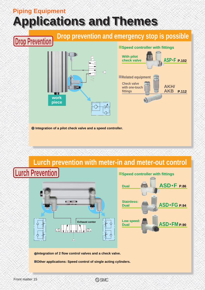
Drop prevention and emergency stop is possible
Integration of a pilot check valve and a speed controller.
Related equipment
With pilot check valve P.102ASP•F
Check valve with one-touch fittings P.112
AKH/AKB
Speed controller with fittings
workpiece
Lurch prevention with meter-in and meter-out control
Integration of 2 flow control valves and a check valve.
Other applications: Speed control of single acting cylinders.
Dual P.86ASD•F
Stainless: Dual P.94ASD•FG
Low speed:Dual P.90ASD•FM
Speed controller with fittings
Exhaust center
Applications and ThemesApplications and Themes
Drop Prevention
Lurch Prevention
Front matter 15

FR one-touch P.54KR
Metal elbow P.97AS•F
FR tubing P.135TRS
FR double layer tubing P.139TRB
P.137TRBU
Fitting
Speed controller with fittings
Tubing
Related equipment
Double layer tubing stripper P.141TKS
Manifold P.59KRM
Self-align P.72H,DL,L,LL
Antistatic P.50KA
Flame resistant (Equivalent to UL-94 Standards V-0)
Double layer tubing
Application: Spot welding.
For use in atmosphere with spatters as in welding work shop
Inner tubingTRB: Nylon11TRBU: Polyurethane
Outer layerTRB: PVC (Equivalent to UL-94 Standards V-0)TRBU: Polyolefin resin
(Equivalent to V-0 in UL-94 Standards)
Piping Equipment Applications and ThemesApplications and Themes
Spatter Proof
Front matter 16

Piping Equipment
One-touch Fittings
Made to order specifications
Brass metal parts: Electroless nickel plated
Lubricant: Vaseline
Lubricant: VaselineBrass metal parts: Electroless nickel plated
No lubrication
Clean series
Note 4)
Note 3)
KQ2 KQ KJ KM KBKCKS KX
Wh
ite
bo
dy
Bla
ck b
od
y
Min
iatu
re o
ne-
tou
ch
Man
ifo
ld
Pip
ing
mo
du
le
Tu
bin
g c
ou
ple
r
Rot
ary
(Sta
ndar
d sp
eed)
Ro
tary
(H
igh
sp
eed
)
P.13 P.13 P.19 P.20 P.20 P.22 P.27P.26
X2
X47
X12
X57
X17
X16
X29
X2
X47
X12
X57
X17
X16
X29
10-
X12
X57
X17
10-
X2
X12
X57
X17
Note 4)Note 5)
Brass metal parts: Electroless nickel plated, Packing O-ring: Fluoro rubber
Lubricant :VaselineBrass metal parts: Electroless nickel platedPacking: Fluororesin coating
Made to Order ProductsMade to Order Products
Packing: Fluororesin coating
Front matter 17

Piping Equipment
DMKDM MKF H,DLL,LL
KPQKPGKG MSKAKP
Mu
lti c
on
nec
tor
Rect
angu
lar m
ulti-
conn
ecto
r
Min
iatu
re
Inse
rt
Sel
f-al
ign
Sta
inle
ss s
teel
Min
iatu
re (
SU
S)
An
tist
atic
Cle
an
Note 1) Only M-5E, M-5ER and M-5M are available for X2.Note 2) Not including M-5UN and MS-5UN.Note 3) Only available for a part of models.Note 4) Not including inch sizes.Note 5) 10-KQ has a white body.Note 6) SUS304 with KPG.
P.32 P.34 P.44
Cle
an
P.49 P.50P.43
KRMKRFl
ame
resi
stan
t man
ifold
Flam
e re
sist
ant
P.58 P.60 P.71 P.75 P.79 P.81
X2
10-
X2
X12
X57
X17
10-
X2
10-
X2X2X2 Note 1)
Note 2)
10- 10-
Standardized Made to order specification available.
Note 6)
Made to Order ProductsMade to Order Products
Front matter 18

Piping Equipment
Speed Controller with Fittings
Tube
Throttle valve (Without check valve)
Lubricant: Vaseline
Throttle valve (Without check valve)Oil free (Sealant material: PTFE coating)
Clean series
Clean series
Made to order specifications
AS•F
Gen
eral
Reel
Change in the number of coil windings and colorChange in the number of tubes and color
Made to order specifications
T
Nyl
on
TS
So
ft
nyl
on
TU
Poly
uret
hane
TCU
Coil
poly
uret
hane
TFU
Poly
uret
hane
flat
ASD•F
Du
al
AS•FMLo
w s
peed
con
trol
ASD•FM
Low
spe
ed c
ontr
oldu
al
AS•FG
Sta
inle
ss s
teel
ASD•FG
Sta
inle
ss d
ual
P.84 P.86 P.88 P.90 P.92 P.94
P.128P.127P.118 P.124P.122
X12
X214
X21
10-
X12
10-
X12
10-
X12
10-
X12
X214
X21
10-
X12
X214
X21
10-
X3 X3 X3X3
10-
X6
10-
X4
10-
Made to Order ProductsMade to Order Products
Front matter 19

TPHTPS
Cle
anpo
lyol
efin
AS•FE
With
res
idua
lpr
essu
re e
xhau
st
ASV•F
Sp
eed
exh
aust
con
tro
ller
ASP•F
Pilo
t with
built
-in c
heck
val
ve
AS•F-TTa
mpe
r pr
oof
AS•F-DASD•F-T
Tam
per p
roof
dua
l
ASD•F-DAS-F
Flam
e re
sist
ant
(Met
al e
lbow
)
P.100 P.101 P.102 P.104 P.108P.106 P.110P.98
Cle
an
P.96
P.129
Standardized
X12
X214
X21
X12 X12 X12
X214
X21
10-
X12
X214
X21
10-
X12
10-
X12
10-
X12
X214
X21
10-
AS•FPQAS•FPG
Standardized
Piping Equipment Made to Order ProductsMade to Order Products
Fla
t h
ead
scr
ewad
just
men
t
Fla
t h
ead
scr
ew
adju
stm
ent
du
al
Front matter 20

Applicable tubing diameter: Metric SizeConnecting thread: M, R, Rc
One-touch Fittings
Fluid
Max. operating pressure
Operating vacuum pressure
Proof pressure
Ambient and fluid temperature
Thread
Sealant (Thread portion)
Air, Water Note 1)
1.0MPa
–100kPa
3.0MPa
–5 to 60°C, In case of water: 0 to 40°C (With no condensation)
JIS B0203 (Taper thread for piping)JIS B0209, Class 2 (Metric coarse thread)
JIS B0211, Class 2 (Metric fine thread)
With / Without sealant
Mounting
Nut
Note 1) Applicable to general industrial water. Consult SMC if using for other fluids. Surge pressure must be under the maximum operating pressure.
ChuckApplicable to nylon and polyurethaneLarge retaining forceSecure engagement with chuck and large retaining force with collet.
Compatible with a wide range of pressure, from low vacuum to 1.0 MPa.The special shape ensures sealing and reduces resistance in tubing insertion.
Series KQ2: Light greySeries KQ : BlueRequires little force for removalReleases the chuck collet to remove the tube as well as to prevent the chuck from biting too deeply into the tubing.
Effective for piping in confined spaceThe body and thread portion can be rotated. (For positioning)
Packing
Stud
Release button
O-ringBody
Tubing
M, R, Rc
Thread
ColletGuide
Series
Series KQ2Series KQ
Body
White
Black
Release button
Light grey
Blue
Tubing material
Tubing outside O.D.
Nylon, Soft Nylon, Polyurethane
ø3.2, ø4, ø6, ø8, ø10, ø12, ø16
Applicable Tubing
Color
Specifications
Series KQ2: White bodySeries KQ : Black body
PAT.
Refer to Best Pneumatics No. 4 for the inch size.
KQ2/White body
KQ/Black body
1

KQ2/KQ
KQ2L
KQ2S
Tubing Male threadTubing Tubing
Tubing One-touch fittings
Accessories
Tubing Female thread hole
Male connector
45°Male elbow
P.3
P.8
P.8
P.8
P.8
P.8
P.8
P.8
P.9
P.9
P.11
P.11
P.11
P.11
P.11
P.9
P.9
P.9
P.9
P.12
P.12
P.12
P.12
P.12
P.12P.9
P.9
P.5
P.3
P.3
P.3
P.6
P.6
P.6
P.6
P.7
P.7
P.4
P.4
P.4
P.4
P.5
P.5
P.10
P.10
P.10
P.10
P.10
P.10
P.10P.5
KQ2K
Hexagon socket head male connector
Male elbow
Extended male elbow
KQ2W
KQ2V
Male branch tee
KQ2T
Hexagon socket head universal male elbow
KQ2VS
Male run tee
KQ2Y
Union"Y"
KQ2U
Double universal male elbow
KQ2VD
Triple universal male elbow
KQ2VT
Branch unionelbow
KQ2LU
Branch universal male elbow
KQ2Z
Double branch universal male elbow
KQ2ZD
Triple branch universal male elbow
KQ2ZT
Deltabranch
KQ2UD
Delta union
KQ2D
Straight unionKQ2H
Different dia. straight
KQ2H
Bulkhead unionKQ2E
Unionelbow
KQ2L
Bulkhead male elbow
KQ2LE
Union tee
KQ2T
Different dia. tee
KQ2T
Different dia. cross
KQ2TY
Union "Y"
KQ2U
Different dia. tee
KQ2T
Different dia. union "Y"
KQ2U
Different dia. double union "Y"
KQ2UD
Branch union elbow
KQ2LU
Deltaunion
KQ2D
Different dia. cross
KQ2TX
Cross
KQ2TW
Plug-in elbow
KQ2L
Extended plug-in elbow
KQ2W
Plug-in reducer
KQ2R
Reducerelbow
KQ2L
Plug-in "Y"
KQ2U
Different dia. plug-in "Y"
KQ2X
Double plug-in "Y"
KQ2XD
Female connector
KQ2F
Bulkhead connector
KQ2E
Female elbow
KQ2LF
KQ2VF
Branch universal female elbow
KQ2ZF
Plug
KQ2P
Adapter
KQ2N
Tubecap
KQ2C
Collarcap
KQ2CDifferent dia. nipple
KQ2N
Nipple
KQ2N
Universal male elbow
KQ2H
One-touch Fitting
P.9
Universal female elbow
2

One-touch FittingsTubing Female thread hole
Male Connector
3.2
4
6
8
10
12
16
M5 X 0.8
M5 X 0.8
M6 X 1
M5 X 0.8
M6 X 1
KQ2H23-M5
-01S
-02S
KQ2H04-M5
-M6
-01S
-02S
KQ2H06-M5
-M6
-01S
-02S
-03S
KQ2H08-01S
-02S
-03S
KQ2H10-01S
-02S
-03S
-04S
KQ2H12-02S
-03S
-04S
KQ2H16-03S
-04S
KQH23-M5
-01S
-02S
KQH04-M5
-M6
-01S
-02S
KQH06-M5
-M6
-01S
-02S
-03S
KQH08-01S
-02S
-03S
KQH10-01S
-02S
-03S
-04S
KQH12-02S
-03S
-04S
KQH16-03S
-04S
Most common style used to pipe from female thread in the same direction.
<M5, M6>
<R>
Hexagon Socket Head Male Connector
The hexagon socket in the body is used to tighten the socket head male connector with a hexagon wrench. Useful in a confined space.
<M5, M6>
<R>
Applicabletubing O.D.
mm
4
6
8
10
12
16
Connecting thread
M5 X 0.8M6 X 1
M5 X 0.8
M6 X 1
Applicabletubing O.D.
mm
Connecting thread
Model
KQ2S04-M5
-M6
-01S
KQ2S06-M5
-M6
-01S
-02S
KQ2S08-01S
-02S
-03S
KQ2S10-01S
-02S
-03S
-04S
KQ2S12-02S
-03S
-04S
KQ2S16-03S
-04S
KQS04-M5
-M6
-01S
KQS06-M5
-M6
-01S
-02S
KQS08-01S
-02S
-03S
KQS10-01S
-02S
-03S
-04S
KQS12-02S
-03S
-04S
KQS16-03S
-04S
KQ2S/KQS
Male ElbowMost common style used to pipe from female thread at aright angle.
<M5>
<M6>
<R>
KQ2L/KQLKQ2H/KQH
KQ2H( ) KQH( )
45° Male Elbow
For piping at 45° from female thread.Intermediate model between male connector and male elbow.
<M5, M6>
<R>
KQ2K/KQK
Applicabletubing O.D.
mm
M5 X 0.8
M6 X 1
M5 X 0.8
M6 X 1
4
6
8
10
12
16
Connecting thread
KQ2K04-M5
-M6
-01S
-02S
KQ2K06-M5
-M6
-01S
-02S
-03S
KQ2K08-01S
-02S
-03S
KQ2K10-01S
-02S
-03S
-04S
KQ2K12-02S
-03S
-04S
KQ2K16-03S
-04S
KQK04-M5
-M6
-01S
-02S
KQK06-M5
-M6
-01S
-02S
-03S
KQK08-01S
-02S
-03S
KQK10-01S
-02S
-03S
-04S
KQK12-02S
-03S
-04S
KQK16-03S
-04S
Applicabletubing O.D.
mm
Connecting thread
3.2M5 X 0.8
M5 X 0.8M6 X 1
M5 X 0.8
M6 X 1
4
6
8
10
12
16
KQ2L23-M5
-01S
-02S
KQ2L04-M5
-M6
-01S
-02S
KQ2L06-M5
-M6
-01S
-02S
-03S
KQ2L08-01S
-02S
-03S
KQ2L10-01S
-02S
-03S
-04S
KQ2L12-02S
-03S
-04S
KQ2L16-03S
-04S
KQL23-M5
-01S
-02S
KQL04-M5
-M6
-01S
-02S
KQL06-M5
-M6
-01S
-02S
-03S
KQL08-01S
-02S
-03S
KQL10-01S
-02S
-03S
-04S
KQL12-02S
-03S
-04S
KQL16-03S
-04S
Model
KQ2S( ) KQS( )
Model
KQ2K (White) KQK (Black)
Model
KQ2L (White) KQL (Black)
R1/8
R1/4
R1/8
R1/4
R1/8
R1/4
R3/8
R1/8
R1/4
R3/8
R1/8
R1/4
R3/8
R1/2
R1/4
R3/8
R1/2
R3/8
R1/2
R1/8
R1/4
R1/8
R1/4
R1/8
R1/4
R3/8
R1/8
R1/4
R3/8
R1/8
R1/4
R3/8
R1/2
R1/4
R3/8
R1/2
R3/8
R1/2
R1/8
R1/8
R1/4
R1/8
R1/4
R3/8
R1/8
R1/4
R3/8
R1/2
R1/4
R3/8
R1/2
R3/8
R1/2
R1/8
R1/4
R1/8
R1/4
R3/8
R1/8
R1/4
R3/8
R1/8
R1/4
R3/8
R1/2
R1/4
R3/8
R1/2
R3/8
R1/2
Release Button, Light grey
Release ButtonBlue
Release Button, Light grey
Release ButtonBlue
3

KQ2/KQ
One-touch FittingsTubing Female thread hole
Extended Male Elbow
3.2
4
6
8
10
12
16
M5 X 0.8
M5 X 0.8
M5 X 0.8
M5 X 0.8
Basically used in the same way as a male elbow.But also used in 3 dimensional piping to prevent interference of fittings.
<M5>
<R>
Applicabletubing O.D.
mm
Connecting thread
Model
KQ2W/KQW
KQ2W (White) KQW (Black)
KQ2W23-M5
-01S
-02S
KQ2W04-M5
-01S
-02S
KQ2W06-M5
-01S
-02S
-03S
KQ2W08-01S
-02S
-03S
KQ2W10-02S
-03S
-04S
KQ2W12-02S
-03S
-04S
KQ2W16-03S
-04S
KQW23-M5
-01S
-02S
KQW04-M5
-01S
-02S
KQW06-M5
-01S
-02S
-03S
KQW08-01S
-02S
-03S
KQW10-02S
-03S
-04S
KQW12-02S
-03S
-04S
KQW16-03S
-04S
<M5>
<R>
Universal Male ElbowThe hexagon head of the body is used to tighten the body with a box wrench in a confined space.
KQ2V/KQV
Applicabletubing O.D.
mm
4
6
8
10
12
16
Connecting thread
KQ2V04-M5
-01S
KQ2V06-M5
-01S
-02S
KQ2V08-01S
-02S
-03S
KQ2V10-02S
-03S
KQ2V12-03S
-04S
KQ2V16-03S
-04S
KQV04-M5
-01S
KQV06-M5
-01S
-02S
KQV08-01S
-02S
-03S
KQV10-02S
-03S
KQV12-03S
-04S
KQV16-03S
-04S
Model
KQ2V (White) KQV (Black)
M5 X 0.8
M5 X 0.8<M5>
<R>
Hexagon Socket Head Universal Male Elbow
The hexagon socket in the head is used to tighten the body with a hexagon wrench. Useful in a confined space.
KQ2VS/KQVS
Applicabletubing O.D.
mm
4
6
8
10
12
Connecting thread
KQ2VS04-M5
-01S
KQ2VS06-M5
-01S
-02S
KQ2VS08-01S
-02S
-03S
KQ2VS10-02S
-03S
KQ2VS12-03S
-04S
KQVS04-M5
-01S
KQVS06-M5
-01S
-02S
KQVS08-01S
-02S
-03S
KQVS10-02S
-03S
KQVS12-03S
-04S
Model
KQ2VS (White) KQVS (Black)
Male Branch Tee
To branch the line from the female thread at 90° in each direction.
KQ2T/KQT
3.2
4
6
8
10
12
16
M5 X 0.8
M5 X 0.8M6 X 1
M6 X 1M5 X 0.8
<M5>
<M6>
<R>
Applicabletubing O.D.
mm
Connecting thread
Model
KQ2T (White) KQT (Black)
KQ2T23-M5
-01S
-02S
KQ2T04-M5
-M6
-01S
-02S
KQ2T06-M5
-M6
-01S
-02S
-03S
KQ2T08-01S
-02S
-03S
KQ2T10-01S
-02S
-03S
-04S
KQ2T12-02S
-03S
-04S
KQ2T16-03S
-04S
KQT23-M5
-01S
-02S
KQT04-M5
-M6
-01S
-02S
KQT06-M5
-M6
-01S
-02S
-03S
KQT08-01S
-02S
-03S
KQT10-01S
-02S
-03S
-04S
KQT12-02S
-03S
-04S
KQT16-03S
-04S
R1/8
R1/4
R1/8
R1/4
R1/8
R1/4
R3/8
R1/8
R1/4
R3/8
R1/4
R3/8
R1/2
R1/4
R3/8
R1/2
R3/8
R1/2
R1/8
R1/8
R1/4
R1/8
R1/4
R3/8
R1/4
R3/8
R3/8
R1/2
R1/8
R1/4
R1/8
R1/4
R1/8
R1/4
R3/8
R1/8
R1/4
R3/8
R1/8
R1/4
R3/8
R1/2
R1/4
R3/8
R1/2
R3/8
R1/2
R1/8
R1/8
R1/4
R1/8
R1/4
R3/8
R1/4
R3/8
R3/8
R1/2
R3/8
R1/2
M5 X 0.8
4

One-touch FittingsTubing Female thread hole
Male Run Tee
To branch the line from the female thread in the same direction and at 90°.
KQ2Y/KQY
3.2
4
6
8
10
12
16
M5 X 0.8
M5 X 0.8M6 X 1
M6 X 1M5 X 0.8
<M5, M6>
Applicabletubing O.D.
mm
Connecting thread
Model
KQ2Y (White) KQY (Black)
KQ2Y23-M5
-01S
-02S
KQ2Y04-M5
-M6
-01S
-02S
KQ2Y06-M5
-M6
-01S
-02S
-03S
KQ2Y08-01S
-02S
-03S
KQ2Y10-01S
-02S
-03S
-04S
KQ2Y12-02S
-03S
-04S
KQ2Y16-03S
-04S
KQY23-M5
-01S
-02S
KQY04-M5
-M6
-01S
-02S
KQY06-M5
-M6
-01S
-02S
-03S
KQY08-01S
-02S
-03S
KQY10-01S
-02S
-03S
-04S
KQY12-02S
-03S
-04S
KQY16-03S
-04S
<R>
Union "Y"
3.2
4
6
8
10
12
16
M5 X 0.8
M5 X 0.8M6 X 1
M5 X 0.8M6 X 1
To branch tubing in the same direction.
<M5, M6>
<R>
Applicabletubing O.D.
mm
Connecting thread
Model
KQ2U/KQU
KQ2U (White) KQU (Black)
KQ2U23-M5
-01S
-02S
KQ2U04-M5
-M6
-01S
-02S
KQ2U06-M5
-M6
-01S
-02S
-03S
KQ2U08-01S
-02S
-03S
KQ2U10-02S
-03S
-04S
KQ2U12-02S
-03S
-04S
KQ2U16-03S
-04S
KQU23-M5
-01S
-02S
KQU04-M5
-M6
-01S
-02S
KQU06-M5
-M6
-01S
-02S
-03S
KQU08-01S
-02S
-03S
KQU10-02S
-03S
-04S
KQU12-02S
-03S
-04S
KQU16-03S
-04S
Double Universal Male Elbow
To branch the line from the female thread at right angles. 2 individual parts rotate freely.
KQ2VD/KQVD
Applicabletubing O.D.
mm
Connecting thread
4
6
8
10
12
Model
KQ2VD (White) KQVD (Black)
KQ2VD04-01S
-02S
-03S
KQ2VD06-01S
-02S
-03S
KQ2VD08-01S
-02S
-03S
-04S
KQ2VD10-02S
-03S
-04S
KQ2VD12-02S
-03S
-04S
KQVD04-01S
-02S
-03S
KQVD06-01S
-02S
-03S
KQVD08-01S
-02S
-03S
-04S
KQVD10-02S
-03S
-04S
KQVD12-02S
-03S
-04S
Triple Universal Male Elbow
4
6
8
10
12
KQ2VT04-01S
-02S
-03S
KQ2VT06-01S
-02S
-03S
KQ2VT08-01S
-02S
-03S
-04S
KQ2VT10-02S
-03S
-04S
KQ2VT12-02S
-03S
-04S
KQVT04-01S
-02S
-03S
KQVT06-01S
-02S
-03S
KQVT08-01S
-02S
-03S
-04S
KQVT10-02S
-03S
-04S
KQVT12-02S
-03S
-04S
To branch line from the female thread into 3 directions at right angles.3 individual parts rotate freely.
Applicabletubing O.D.
mm
Connecting thread
Model
KQ2VT/KQVT
KQ2VT (White) KQVT (Black)
R1/8
R1/4
R1/8
R1/4
R1/8
R1/4
R3/8
R1/8
R1/4
R3/8
R1/8
R1/4
R3/8
R1/2
R1/4
R3/8
R1/2
R3/8
R1/2
R1/8
R1/4
R1/8
R1/4
R1/8
R1/4
R3/8
R1/8
R1/4
R3/8
R1/4
R3/8
R1/2
R1/4
R3/8
R1/2
R3/8
R1/2
R1/8
R1/4
R3/8
R1/8
R1/4
R3/8
R1/8
R1/4
R3/8
R1/2
R1/4
R3/8
R1/2
R1/4
R3/8
R1/2
R1/8
R1/4
R3/8
R1/8
R1/4
R3/8
R1/8
R1/4
R3/8
R1/2
R1/4
R3/8
R1/2
R1/4
R3/8
R1/2
5

KQ2/KQ
One-touch FittingsTubing Female thread hole
Branch Union Elbow
4
6
8
10
12
M5 X 0.8
M5 X 0.8
M6 X 1
M6 X 1
KQ2LU04-M5
-M6
-01S
-02S
KQ2LU06-M5
-M6
-01S
-02S
-03S
KQ2LU08-01S
-02S
-03S
KQ2LU10-02S
-03S
-04S
KQ2LU12-02S
-03S
-04S
KQLU04-M5
-M6
-01S
-02S
KQLU06-M5
-M6
-01S
-02S
-03S
KQLU08-01S
-02S
-03S
KQLU10-02S
-03S
-04S
KQLU12-02S
-03S
-04S
To branch tubing at a right angle from the female thread.
<M5, M6>
<R>
Applicabletubing O.D.
mm
Connecting thread
Model
KQ2LU (White) KQLU (Black)
Branch Universal Male Elbow
The hexagon head of the body is used to tighten the body with a box wrench. Used to branch the line. Elbow union for piping.
<M5>
<R>
Applicabletubing O.D.
mm
4
6
8
10
12
Connecting thread
M5 X 0.8 KQ2Z04-M5
-01S
KQ2Z06-01S
-02S
-03S
KQ2Z08-01S
-02S
-03S
KQ2Z10-02S
-03S
KQ2Z12-03S
-04S
KQZ04-M5
-01S
KQZ06-01S
-02S
-03S
KQZ08-01S
-02S
-03S
KQZ10-02S
-03S
KQZ12-03S
-04S
Model
KQ2Z (White) KQZ (Black)
Double Branch Universal Male Elbow
To branch the line from the female thread into 4 tubes at right angles. 2 individual parts rotate freely.
KQ2ZD/KQZD
Applicabletubing O.D.
mm
Connecting thread
4
6
8
10
12
KQ2ZD04-01S
-02S
-03S
KQ2ZD06-01S
-02S
-03S
KQ2ZD08-01S
-02S
-03S
-04S
KQ2ZD10-02S
-03S
-04S
KQ2ZD12-02S
-03S
-04S
KQZD04-01S
-02S
-03S
KQZD06-01S
-02S
-03S
KQZD08-01S
-02S
-03S
-04S
KQZD10-02S
-03S
-04S
KQZD12-02S
-03S
-04S
Model
KQ2ZD (White) KQZD (Black)
Triple Branch Universal Male Elbow
4
6
8
10
12
To branch the line from the female thread into 6 tubes at right angles. 3 individual parts rotate freely.
Applicabletubing O.D.
mm
Connecting thread
Model
KQ2ZT/KQZT
KQ2ZT (White) KQZT (Black)
KQ2ZT04-01S
-02S
-03S
KQ2ZT06-01S
-02S
-03S
KQ2ZT08-01S
-02S
-03S
-04S
KQ2ZT10-02S
-03S
-04S
KQ2ZT12-02S
-03S
-04S
KQZT04-01S
-02S
-03S
KQZT06-01S
-02S
-03S
KQZT08-01S
-02S
-03S
-04S
KQZT10-02S
-03S
-04S
KQZT12-02S
-03S
-04S
R1/8
R1/4
R1/8
R1/4
R3/8
R1/8
R1/4
R3/8
R1/4
R3/8
R1/2
R1/4
R3/8
R1/2
R1/8
R1/4
R3/8
R1/8
R1/4
R3/8
R1/8
R1/4
R3/8
R1/2
R1/4
R3/8
R1/2
R1/4
R3/8
R1/2
R1/8
R1/4
R3/8
R1/8
R1/4
R3/8
R1/8
R1/4
R3/8
R1/2
R1/4
R3/8
R1/2
R1/4
R3/8
R1/2
R1/8
R1/8
R1/4
R3/8
R1/8
R1/4
R3/8
R1/4
R3/8
R3/8
R1/2
KQ2LU/KQLU
KQ2Z/KQZ
KQ2/KQ
6

One-touch FittingsTubing Female thread hole
Delta Branch
To branch the line from the female thread into 4 tubes in the same direction.
KQ2UD/KQUD
4
6
Applicabletubing O.D.
mm
Connecting thread
Model
KQ2UD (White) KQUD (Black)
KQ2UD04-01S
-02S
KQ2UD06-01S
-02S
KQUD04-01S
-02S
KQUD06-01S
-02S
Delta Union
To branch the line from the female thread into 2 directions at right angles.
4
6
8
10
12
M5 X 0.8
M5 X 0.8
M6 X 1
M6 X 1
<M5, M6>
Applicabletubing O.D.
mm
Connecting thread
Model
KQ2D (White) KQD (Black)
KQ2D04-M5
-M6
-01S
-02S
KQ2D06-M5
-M6
-01S
-02S
-03S
KQ2D08-01S
-02S
-03S
KQ2D10-02S
-03S
-04S
KQ2D12-02S
-03S
-04S
KQD04-M5
-M6
-01S
-02S
KQD06-M5
-M6
-01S
-02S
-03S
KQD08-01S
-02S
-03S
KQD10-02S
-03S
-04S
KQD12-02S
-03S
-04S
<R>
R1/8
R1/4
R1/8
R1/4
R1/8
R1/4
R1/8
R1/4
R3/8
R1/8
R1/4
R3/8
R1/4
R3/8
R1/2
R1/4
R3/8
R1/2
KQ2D/KQD
7

KQ2/KQ
One-touch Fittings
Straight Union
To connect tubings in the same direction.
KQ2H/KQH
Applicable tubing O.D.mm
3.2468101216
KQ2H23-00
KQ2H04-00
KQ2H06-00
KQ2H08-00
KQ2H10-00
KQ2H12-00
KQ2H16-00
KQH23-00
KQH04-00
KQH06-00
KQH08-00
KQH10-00
KQH12-00
KQH16-00
Model
KQ2H (White) KQH (Black)
Bulkhead Union
To connect tubing through a panel.
KQ2E/KQE
Applicable tubing O.D.mm
3.2468101216
KQ2E23-00
KQ2E04-00
KQ2E06-00
KQ2E08-00
KQ2E10-00
KQ2E12-00
KQ2E16-00
KQE23-00
KQE04-00
KQE06-00
KQE08-00
KQE10-00
KQE12-00
KQE16-00
Model
KQ2E( ) KQE( )
Union Elbow
3.2468101216
To connect tubing at right angles to each other.
Applicable tubing O.D.mm
Model
KQ2L/KQL
KQ2L (White) KQL (Black)
KQ2L23-00
KQ2L04-00
KQ2L06-00
KQ2L08-00
KQ2L10-00
KQ2L12-00
KQ2L16-00
KQL23-00
KQL04-00
KQL06-00
KQL08-00
KQL10-00
KQL12-00
KQL16-00
Tubing Tubing
Bulkhead Male Elbow
To connect tubings through a panel and change the tubing entry by 90°.
KQ2LE/KQLE
Applicable tubing O.D.mm
468
1012
KQ2LE04-00
KQ2LE06-00
KQ2LE08-00
KQ2LE10-00
KQ2LE12-00
KQLE04-00
KQLE06-00
KQLE08-00
KQLE10-00
KQLE12-00
Model
KQ2LE (White) KQLE (Black)
Union Tee
To branch tubing into 2 directions each at 90° to the original one.
KQ2T/KQT
Applicable tubing O.D.mm
3.2468
101216
KQ2T23-00
KQ2T04-00
KQ2T06-00
KQ2T08-00
KQ2T10-00
KQ2T12-00
KQ2T16-00
KQT23-00
KQT04-00
KQT06-00
KQT08-00
KQT10-00
KQT12-00
KQT16-00
Model
KQ2T (White) KQT (Black)
Union "Y"
To branch tubing in the same direction.
KQ2U/KQU
Applicable tubing O.D.mm
3.2468
101216
KQ2U23-00
KQ2U04-00
KQ2U06-00
KQ2U08-00
KQ2U10-00
KQ2U12-00
KQ2U16-00
KQU23-00
KQU04-00
KQU06-00
KQU08-00
KQU10-00
KQU12-00
KQU16-00
Model
KQ2U (White) KQU (Black)
Different Dia. Straight
To connect tubings of different diameters.
KQ2H/KQH
Applicable tubing O.D.mm
3.2468
1012
b468
101216
KQ2H23-04
KQ2H04-06
KQ2H06-08
KQ2H08-10
KQ2H10-12
KQ2H12-16
KQH23-04
KQH04-06
KQH06-08
KQH08-10
KQH10-12
KQH12-16
Model
KQ2H (White) KQH (Black)ba a
Release button,Light grey
Release buttonBlue
8

One-touch FittingsTubing Tubing
Different Dia. Tee
To branch the tubing into two at a right angle and reducethe resulting branches in size.
KQ2T/KQT
Applicable tubing O.D.mm
a3.24681012
b468101216
KQ2T23-04
KQ2T04-06
KQ2T06-08
KQ2T08-10
KQ2T10-12
KQ2T12-16
Model
KQ2T (White)
KQT23-04
KQT04-06
KQT06-08
KQT08-10
KQT10-12
KQT12-16
KQT (Black)
2- a
b
Different Dia. Tee
To connect tubing in the same direction as well as to branch it into another smaller tubing at 90°.
KQ2T
Applicable tubing O.D.mm
a681012
b46810
KQ2T06-04
KQ2T08-06
KQ2T10-08
KQ2T12-10
Model
KQ2T (White)
2- a
b
Different Dia. Union "Y"
To branch tubing into 2 smaller tubes in the same direction as the original one.
KQ2U/KQU
Applicable tubing O.D.mm
a3.24681012
b468101216
KQ2U23-04
KQ2U04-06
KQ2U06-08
KQ2U08-10
KQ2U10-12
KQ2U12-16
KQU23-04
KQU04-06
KQU06-08
KQU08-10
KQU10-12
KQU12-16
Model
KQ2U (White) KQU (Black)a a
b
Different Dia. Double Union "Y"
To branch tubing into 4 smaller tubes in the same direction as the original one.
KQ2UD/KQUD
Applicable tubing O.D.mm
a46
b68
KQ2UD04-06
KQ2UD06-08
KQUD04-06
KQUD06-08
Model
KQ2UD (White) KQUD (Black)
4- a
b
468
1012
Applicable tubing O.D.mm
Branch Union Elbow
To branch a tube at a right angle into two tubes.
Model
KQ2LU/KQLU
KQ2LU (White) KQLU (Black)
KQ2LU04-00
KQ2LU06-00
KQ2LU08-00
KQ2LU10-00
KQ2LU12-00
KQLU04-00
KQLU06-00
KQLU08-00
KQLU10-00
KQLU12-00
Delta Union
To connect 3 tubes at right angles with each other.
KQ2D/KQD
Applicable tubing O.D.mm
468
1012
KQ2D04-00
KQ2D06-00
KQ2D08-00
KQ2D10-00
KQ2D12-00
KQD04-00
KQD06-00
KQD08-00
KQD10-00
KQD12-00
Model
KQ2D (White) KQD (Black)
Cross
To branch tubing into 4 directions.
KQ2TW
Applicable tubing O.D.mm
468
1012
KQ2TW04-00
KQ2TW06-00
KQ2TW08-00
KQ2TW10-00
KQ2TW12-00
Model
KQ2TW (White)
Different Dia. Cross
To connect 4 tubes at right angles with 2 smaller tubes on both sides.
KQ2TX
Applicable tubing O.D.mm
a68
10
b8
1012
KQ2TX06-08
KQ2TX08-10
KQ2TX10-12
Model
KQ2TX (White)
b ba
a
KQT (Black) is manufactured as a made to order.
This model is not available with black body specifications.
This model is not available with black body specifications.
Different Dia. Cross
To branch tubing into smaller tubing in 3 directions.
KQ2TY
Applicable tubing O.D.mm
a68
10
b8
1012
KQ2TY06-08
KQ2TY08-10
KQ2TY10-12
Model
KQ2TY (White)
3- a
b
This model is not available with black body specifications.
9

KQ2/KQ
One-touch FittingsTubing One-touch fittings
Plug-in Elbow
To change the tubing direction from a one-touch fitting by 90°.
KQ2L/KQL
Applicabletubing O.D.
mm
3.2468101216
Fitting size
3.2468101216
KQ2L23-99
KQ2L04-99
KQ2L06-99
KQ2L08-99
KQ2L10-99
KQ2L12-99
KQ2L16-99
KQL23-99
KQL04-99
KQL06-99
KQL08-99
KQL10-99
KQL12-99
KQL16-99
Model
KQ2L (White) KQL (Black)
Extended Plug-in Elbow
To change the tubing direction from a one-touch fitting by 90°. Applicable to 3 dimensional piping when used with a plug-in elbow.
KQ2W/KQW
Applicabletubing O.D.
mm
3.24681012
Fitting size
3.24681012
KQ2W23-99
KQ2W04-99
KQ2W06-99
KQ2W08-99
KQ2W10-99
KQ2W12-99
KQW23-99
KQW04-99
KQW06-99
KQW08-99
KQW10-99
KQW12-99
Model
KQ2W (White) KQW (Black)
Plug-in Reducer
To connect to a smaller one-touch fitting.
KQ2R/KQR
Applicabletubing O.D.
mmFitting size
3.2
4
12
10
8
6
468104810121012121616
KQ2R23-04
KQ2R04-06
-08
-10
KQ2R06-04
-08
-10
-12
KQ2R08-10
-12
KQ2R10-12
-16
KQ2R12-16
KQR23-04
KQR04-06
-08
-10
KQR06-04
-08
-10
-12
KQR08-10
-12
KQR10-12
-16
KQR12-16
Model
KQ2R (White) KQR (Black)
Reducer Elbow
To change the tubing direction from a one-touch fitting by 90° as well as to connect to tubing of a smaller diameter.
KQ2L/KQL
Applicabletubing O.D.
mm
3.2
4
6
8
1012
Fitting size
4688
1010121216
KQ2L23-04
KQ2L04-06
-08
KQ2L06-08
-10
KQ2L08-10
-12
KQ2L10-12
KQ2L12-16
KQL23-04
KQL04-06
-08
KQL06-08
-10
KQL08-10
-12
KQL10-12
KQL12-16
Model
KQ2L (White) KQL (Black)
Plug-in "Y"
To branch the line from a one-touch fitting into tubing in the same direction.
KQ2U/KQU
Applicabletubing O.D.
mmFitting size
3.2468
101216
3.2468
101216
KQ2U23-99
KQ2U04-99
KQ2U06-99
KQ2U08-99
KQ2U10-99
KQ2U12-99
KQ2U16-99
KQU23-99
KQU04-99
KQU06-99
KQU08-99
KQU10-99
KQU12-99
KQU16-99
Model
KQ2U (White) KQU (Black)
Different Dia. Plug-in "Y"
To branch the line from a one-touch fitting into tubing of a smaller diameter in the same direction.
KQ2X/KQX
Applicabletubing O.D.
mmFitting size
468
10
68
1012
KQ2X04-06
KQ2X06-08
KQ2X08-10
KQ2X10-12
KQX04-06
KQX06-08
KQX08-10
KQX10-12
Model
KQ2X (White) KQX (Black)
Double Branch "Y"
To branch the line from a one-touch fitting into 4 tubes of a smaller diameter in the same direction.
KQ2XD/KQXD
Applicabletubing O.D.
mmFitting size
46
68
KQ2XD04-06
KQ2XD06-08
KQXD04-06
KQXD06-08
Model
KQ2XD (White) KQXD (Black)
10

One-touch Fittings
Female Connector
To pipe from the male threaded portion of a pressure gauge, etc.
KQ2F/KQF
Applicabletubing O.D.
mm
4
6
8
10
12
16
Connecting thread
KQ2F04-01
-02
KQ2F06-01
-02
-03
KQ2F08-01
-02
-03
KQ2F10-02
-03
KQ2F12-02
-03
-04
KQ2F16-03
-04
KQF04-01
-02
KQF06-01
-02
-03
KQF08-01
-02
-03
KQF10-02
-03
KQF12-02
-03
-04
KQF16-03
-04
Model
KQ2F( ) KQF( )
TubingMale thread
Bulkhead Female Connector
3.2
4
6
8
10
12
16
Used for trunk connection between tubing and a male thread installed through a panel.
Applicabletubing O.D.
mm
Model
KQ2E/KQE
KQ2E( ) KQE( )KQ2E23-02
KQ2E04-01
-02
KQ2E06-01
-02
-03
KQ2E08-01
-02
-03
KQ2E10-02
-03
KQ2E12-03
-04
KQ2E16-03
-04
KQE23-02
KQE04-01
-02
KQE06-01
-02
-03
KQE08-01
-02
-03
KQE10-02
-03
KQE12-03
-04
KQE16-03
-04
Connecting thread
Female Elbow
To pipe from the male threaded at the right angle.
<M5, M6>
<Rc>
KQ2LF/KQLF
Applicabletubing O.D.
mm
M5 X 0.8
M6 X 1
M5 X 0.8
M6 X 1
4
6
8
10
12
Connecting thread
KQ2LF04-M5
-M6
-01
-02
KQ2LF06-M5
-M6
-01
-02
-03
KQ2LF08-01
-02
-03
KQ2LF10-02
-03
-04
KQ2LF12-02
-03
-04
KQLF04-M5
-M6
-01
-02
KQLF06-M5
-M6
-01
-02
-03
KQLF08-01
-02
-03
KQLF10-02
-03
-04
KQLF12-02
-03
-04
Model
KQ2LF (White) KQLF (Black)
Universal Female Elbow
4
6
8
10
12
M5 X 0.8
M5 X 0.8
To connect a line from a male and female thread in the same direction as well as to branch it into 2 pipes at a right angle. Multiplex connections possible.
<M5>
<R, Rc>
Applicabletubing O.D.
mm
Connecting thread
Model
KQ2VF/KQVF
KQ2VF (White) KQVF (Black)
KQ2VF04-M5
-01S
KQ2VF06-M5
-01S
-02S
KQ2VF08-01S
-02S
-03S
KQ2VF10-02S
-03S
KQ2VF12-03S
-04S
KQVF04-M5
-01S
KQVF06-M5
-01S
-02S
KQVF08-01S
-02S
-03S
KQVF10-02S
-03S
KQVF12-03S
-04S
Rc1/8
Rc1/4
Rc1/8
Rc1/4
Rc3/8
Rc1/8
Rc1/4
Rc3/8
Rc1/4
Rc3/8
Rc1/4
Rc3/8
Rc1/2
Rc3/8
Rc1/2
Rc1/4
Rc1/8
Rc1/4
Rc1/8
Rc1/4
Rc3/8
Rc1/8
Rc1/4
Rc3/8
Rc1/4
Rc3/8
Rc3/8
Rc1/2
Rc3/8
Rc1/2
Rc1/8
Rc1/4
Rc1/8
Rc1/4
Rc3/8
Rc1/8
Rc1/4
Rc3/8
Rc1/4
Rc3/8
Rc1/2
Rc1/4
Rc3/8
Rc1/2
R/Rc1/8
R/Rc1/8
R/Rc1/4
R/Rc1/8
R/Rc1/4
R/Rc3/8
R/Rc1/4
R/Rc3/8
R/Rc3/8
R/Rc1/2
Branch Universal Female Elbow
To branch a line from a male or female thread in the same direction and at a right angle. Multiplex connections possible.
<M5>
KQ2ZF/KQZF
Applicabletubing O.D.
mm
M5 X 0.84
6
8
10
12
Connecting thread
KQ2ZF04-M5
-01S
KQ2ZF06-01S
-02S
KQ2ZF08-01S
-02S
KQ2ZF10-02S
-03S
KQ2ZF12-03S
-04S
KQZF04-M5
-01S
KQZF06-01S
-02S
KQZF08-01S
-02S
KQZF10-02S
-03S
KQZF12-03S
-04S
Model
KQ2ZF (White) KQZF (Black)
<R, Rc>
R/Rc1/8
R/Rc1/8
R/Rc1/4
R/Rc1/8
R/Rc1/4
R/Rc1/4
R/Rc3/8
R/Rc3/8
R/Rc1/2
Release button, Light grey
Release buttonBlue
Release button, Light grey
Release buttonBlue
11

KQ2/KQ
One-touch FittingsAccessory
Color Cap
4
3.2
6
8101216
Attached to release buttons for various applications to distinguish them by color.
Applicabletubing O.D.
mmModel Application
KQ2CNipple
To connect 2 one-touch fittings.
KQ2N/KQN
Applicable fitting size
468101216
KQ2N04-99
KQ2N06-99
KQ2N08-99
KQ2N10-99
KQ2N12-99
KQ2N16-99
KQN04-99
KQN06-99
KQN08-99
KQN10-99
KQN12-99
KQN16-99
Model
KQ2N (White) KQN (Black)
KQ2C-04
KQ2C-04A-
KQ2C-04B-
KQ2C-06
KQ2C-06A-
KQ2C-06B-
KQ2C-08KQ2C-10KQ2C-12KQ2C-16
KQ2C-01KQ2C-01A-
KQ2C-01B-
KQH, KQ2H04-M5, M6KQS, KQ2S04-M5, M6
KQH, KQ2H23-M5
KQL, KQ2L04-M5, M6KQT, KQ2T04-M5, M6KQY, KQ2Y04-M5, M6
KQL, KQ2L23-M5KQT, KQ2T23-M5KQY, KQ2Y23-M5
KQH, KQ2H06-M5, M6KQS, KQ2S06-M5, M6
KQL, KQ2L06-M5, M6KQT, KQ2T06-M5, M6KQY, KQ2Y06-M5, M6
Different Dia. Nipple
To connect one-touch fittings of different sizes.
KQ2N/KQN
Applicable fitting size
a4681012
b68101216
KQ2N04-06
KQ2N06-08
KQ2N08-10
KQ2N10-12
KQ2N12-16
KQN04-06
KQN06-08
KQN08-10
KQN10-12
KQN12-16
Model
KQ2N (White) KQN (Black)
Tubing Cap
To plug unused tubing.
KQ2C/KQC
Applicable tubing O.D.mm
468
101216
KQ2C04-00
KQ2C06-00
KQ2C08-00
KQ2C10-00
KQ2C12-00
KQ2C16-00
KQC04-00
KQC06-00
KQC08-00
KQC10-00
KQC12-00
KQC16-00
Model
KQ2C (White) KQC (Black)
Plug
To plug unused one-touch fittings KQ2P (White), KQP (Blue).
KQ2P/KQP
Applicable fitting size
3.2468101216
KQ2P-23
KQ2P-04
KQ2P-06
KQ2P-08
KQ2P-10
KQ2P-12
KQ2P-16
KQP-23
KQP-04
KQP-06
KQP-08
KQP-10
KQP-12
KQP-16
Model
KQ2P (White) KQP (Black)
B (Black), R (Red), YR (Orange), BR (Brown), Y (Yellow), G (Green), CB (Sky blue), GR (Gray), W (White), BU (Blue)
Connecting thread
Adapter
To connect a one-touch fitting and R female thread.
KQ2N/KQN
Applicablefittingsize
4
6
8
10
KQ2N04-M5
-01S
KQ2N06-M5
-01S
-02S
KQ2N08-02S
-03S
KQ2N10-03S
KQN04-M5
-01S
KQN06-M5
-01S
-02S
KQN08-02S
-03S
KQN10-03S
Model
KQ2N (White) KQN (Black)
M5 X 0.8
M5 X 0.8
ba
R1/8
R1/8
R1/4
R1/4
R3/8
R3/8
12

Made to OrderOrderMade
Electroless Nickel Plated on Brass Parts
(Example) KQ2H06-02S-X2
X2
No Lubrication
(Example) KQ2H06-02S-X57
X57
Electroless Nickel Plating on Brass Parts (X2)Seal, O-ring: Fluororesin Rubber
(Example) KQ2H06-02S-X47
X47
Lubricant: Vaseline
(Example) KQ2H06-02S-X12
X12
(Example) KQ2H06-02S-X17
X17
Electroless Nickel Plating on Brass Parts (X2)Seal: Fluororesin CoatingOil Free: No Lubrication (X17)
Seal: Fluororesin CoatingOil Free: No Lubrication
(Example) KQ2H06-02S-X29
X29
Electroless Nickel Plating on Brass Parts (X2)Lubricant: Vaseline (X12)
(Example) KQ2H06-02S-X16
X16
Clean Series
Electroless nickel plating on brass parts (X2)Lubricant: Fluororesin greaseDouble packagingResin bodyrelease button: White
(Example) 10-KQH06-02S
10-
13

KJ
Applicable tubing O.D.: Metric SizeConnecting thread: M3, M5, R1/8
One-touch Mini
Fluid
Max. operating pressure
Operating vacuum pressure
Proof pressure
Ambient and fluid temperature
Thread
Thread label (Standard)
For application requiring copper-free material (Standard)
Air, Water Note1)
1.0MPa
–100kPa
3.0MPa
–5 to 60°C, In case of water: 0 to 40°C (with no condensation)
JIS B0203 (Taper thread for piping)JIS B0209, Class 2 (Metric coarse thread)
JIS B0211, Class 2 (Metric fine thread)
With sealant
Brass parts are all electroless nickel plated.
Mounting
Nut
Note1) Applicable to general industrial water. Consult SMC if using for other fluids.Surge pressure must be under the maximum operating pressure.
Tubing material
Tubing O.D.
Nylon, Soft nylon, Polyurethane
ø3.2, ø4, ø6
Applicable Tubing
Specifications
PAT.
Refer to Best Pneumatics vol. 4 for the inch size.
ChuckApplicable to nylon and polyurethane.Large retaining force.Secure engagement and large retaining force with chuck.
Compatible with low vacuum to 1.0 MPa of pressure.The special shape ensures sealing and reduces resistance of tubing insertion.
Requires little force for removal.Releases the chuck to remove the tubing.Prevents the chuck from biting too deeply into the tubing.Tubing removal is easier.
Enables piping in a narrower space.Body and thread can be rotated (For positioning).Electroless nickel plated.R1/8 thread with sealant.
Packing
Stud
Release bush (Light grey)
O-ringBody (White)Tubing
Gasket
Guide 2Guide 1
Outside diameter reduced by 20% (Compared with series KQ), allowing piping in a narrower space.
Thread sealant as standard.For application requiring copper-free material.(Electroless nickel plating)
Compatible with vacuum to –100 kPa of pressure.
14

Reducer union plug-in "Y"
KJX
KJL
KJS
Tubing Male thread
Tubing Tubing Tubing One-touch fittingsTubing Female thread hole
Male connector
Extended male elbow
P.16
P.17
P.17
P.17
P.17
P.17
P.17
P.17P.18
P.17
P.16
P.16
P.16
P.16
P.16
P.16
P.18
P.18
P.18
P.18
KJW
Hexagon socket head male connector
Male elbow
Male branch tee
KJT
KJY
Branch "Y"
KJU
Straightunion
KJH
Different dia. tee
KJT
Bulkhead union
KJE
Union elbow
KJL
Union tee
KJT
Union "Y"
KJU
Different dia. union "Y"
KJU
Different dia. straight
KJH
Plug-in elbow
KJL
Reducer
KJR
Reducerelbow
KJL
Plug-in "Y"
KJU
Female connector
KJF
Male run tee
KJH
P.18
15

KJ
Miniature One-touchTubing Female thread hole
Male Connector
3.2
4
6
M5 X 0.8
M3 X 0.5
M3 X 0.5
M5 X 0.8
M5 X 0.8
KJH23-M3
-M5
-01S
KJH04-M3
-M5
-01S
KJH06-M5
-01S
Most common style used to pipe from female thread in the same direction.
<M3, M5>
<R1/8> <R1/8>
<R1/8>
Hexagon Socket Head Male Connector
The hexagon socket in the body is used to tighten the socket head male connector with a hexagon wrench. Useful in a confined space.
Applicabletubing O.D.
mm
3.2
6
4
Connecting thread
M3 X 0.5
M3 X 0.5
M5 X 0.8
M5 X 0.8
M5 X 0.8
Applicabletubing O.D.
mm
Connecting thread Model
KJS23-M3
-M5
KJS04-M3
-M5
-01S
KJS06-M5
-01S
KJS
KJH Extended Male Elbow
Basically used in the same way as a male elbow.But also used in 3 dimensional piping to prevent interference of fittings.
<M3, M5>
KJW
Applicabletubing O.D.
mm
M3 X 0.5
M3 X 0.5
M5 X 0.8
M5 X 0.8
3.2
4
6
Connecting thread
M5 X 0.8
KJW23-M3
-M5
-01S
KJW04-M3
-M5
-01S
KJW06-M5
-01S
Model
Model
<R1/8>
Male Branch Tee
To branch the line from the female thread at 90° in each direction.
<M3, M5>
KJT
Applicabletubing O.D.
mm
M3 X 0.5
M3 X 0.5
M5 X 0.8
M5 X 0.8
3.2
4
6
Connecting thread
M5 X 0.8
KJT23-M3
-M5
-01S
KJT04-M3
-M5
-01S
KJT06-M5
-01S
Model
<M3, M5>
<R1/8>
Male Elbow
Most common style used to pipe from female thread at a right angle.
Applicabletubing O.D.
mm
3.2
6
4
Connecting thread
M3 X 0.5
M3 X 0.5
M5 X 0.8
M5 X 0.8
M5 X 0.8KJL23-M3
-M5
-01S
KJL04-M3
-M5
-01S
KJL06-M5
-01S
KJL
Model
<M3, M5>
<R1/8>
Male Run Tee
To branch the line from the female thread in the same direction and at 90°.
<M3, M5>
KJY
Applicabletubing O.D.
mm
M3 X 0.5
M3 X 0.5
M5 X 0.8
M5 X 0.8
3.2
4
6
Connecting thread
M5 X 0.8
KJY23-M3
-M5
-01S
KJY04-M3
-M5
-01S
KJY06-M5
-01S
Model
Branch "Y"
3.2
4
6
M5 X 0.8
M5 X 0.8
M5 X 0.8
KJU23-M5
-01S
KJU04-M5
-01S
KJU06-M5
-01S
To branch a tubing in the same direction.
<M5>
<R1/8>
Applicabletubing O.D.
mm
Connecting thread Model
KJU
R1/8
R1/8
R1/8
R1/8
R1/8
R1/8
R1/8
R1/8
R1/8
R1/8
R1/8
R1/8
R1/8
R1/8
R1/8
R1/8
R1/8
R1/8
R1/8
R1/8
KJ
16

Miniature One-touch
Straight Union
To connect tubing in the same direction.
KJH
Applicable tubing O.D.mm
3.246
KJH23-00
KJH04-00
KJH06-00
Model
Bulkhead Union
To connect tubing through a panel.
KJE
Applicable tubing O.D.mm
3.246
KJE23-00
KJE04-00
KJE06-00
Model
Union Elbow
3.246
To connect tubing at right angles to each other.
Applicable tubing O.D.mm
Model
KJL
KJL23-00
KJL04-00
KJL06-00
Union Tee
3.246
To branch tubing into 2 directions each at 90° to the original one.
Applicable tubing O.D.mm
Model
KJT
KJT23-00
KJT04-00
KJT06-00
Union "Y"
3.246
To branch tubing in the same direction.
Applicable tubing O.D.mm
Model
KJU
KJU23-00
KJU04-00
KJU06-00
Tubing Tubing
Different Dia. Straight
To connect tubing of different diameters.
KJH
Applicable tubing O.D.mm
3.2
4
b466
KJH23-04
-06
KJH04-06
Model
Different Dia. Tee
To branch the tubing into two at a right angle and reduce the resulting branches in size.
KJT
Applicable tubing O.D.mm
a3.24
b46
KJT23-04
KJT04-06
Model
2- a
b
ba
Different Dia. Union "Y"
To branch tubing into 2 smaller tubing in the same direction as the original one.
KJU
Applicable tubing O.D.mm
a3.24
b46
KJU23-04
KJU04-06
Model2- a
b
a
17

KJ
Miniature One-touchTubing One-touch Fittings
Plug-in Elbow
To change the tubing direction from a one-touch fitting by 90°.
KJL
Applicabletubing O.D.
mm
3.246
Aplicablefitting size
3.246
KJL23-99
KJL04-99
KJL06-99
Model
Plug-in Reducer
To connect to a smaller one-touch fitting.
KJR
Applicabletubing O.D.
mm
Applicablefitting size
3.2
4
466
KJR23-04
-06
KJR04-06
Model
Reducer Elbow
To change the tubing direction from a one-touch fitting by 90° as well as to connect to a tubing of a smaller diameter.
KJL
Applicabletubing O.D.
mm
Applicablefitting size
3.2
4
466
KJL23-04
-06
KJL04-06
Model
Plug-in "Y"
To branch the line from a one-touch fitting into tubing in the same direction.
KJU
Applicabletubing O.D.
mm
Applicablefitting size
3.246
3.246
KJU23-99
KJU04-99
KJU06-99
Model
Reducer Union Plug-in "Y"
To branch the line from a one-touch fitting into smaller diameter in the same direction.
KJX
Applicabletubing O.D.
mm
Applicablefitting size
3.24
46
KJX23-04
KJX04-06
Model
Miniature One-touch
Female Connector
To pipe from the male threaded portion of a pressure gauge, etc.
KJF
Applicabletubing O.D.
mm
3.2
6
4
Connecting thread
KJF23-M3
-M5
KJF04-M3
-M5
KJF06-M5
Model
Tubing Male thread
M3 X 0.5
M5 X 0.8
M3 X 0.5
M5 X 0.8
M5 X 0.8
KJ
18

Made to OrderOrderMade
(Example) KJH06-01S-X17
X17 Lubricant: Vaseline
(Example) KJH06-01S-X12
X12 Clean Series
Lubricant: Fluororesin greaseDouble packaging
(Example) 10-KJH06-01S
10-Seal, O-ring: Fluororesin CoatingOil Free: No Lubrication
No Lubrication
(Example) KJH06-01S-X57
X57
19

KS/KX
Applicable tubing O.D.: Metric SizeConnecting thread: M,R
Rotary One-touch Fittings
Fluid
Max. operating pressure
Operating vacuum pressure
Proof pressure
Ambient and fluid temperature
Thread
Air
1.0MPa
–100kPa
3.0MPa
–5 to 60°C (With no condensation)
JIS B0203 (Taper thread for piping)JIS B0209, Class 2 (Metric coarse thread)
HolderElectroless nickel plating allows copper-free applications.
The special rotary seal minimizes rotating torque and friction.
Low-torque, low-friction operation with oil containing slide bearing.
The ball bearing ensures low-torque rotation.
Series KS: BlueSeries KX: WhiteThe male connector is provided with a tubing rotation prevention mechanism.
Ball bearing
Cassette
Electroless nickel plating allows copper-free applications.Thread sealant is standardized.
Stud
Rotary seal
Slide bearing
Tubing material
Tubing O.D.
Nylon, soft nylon, Polyurethane
ø4, ø6, ø8, ø10, ø12
Applicable Tubing
Specifications
Applicable tubing O.D.
Rotating torque N·m
Allowable number of rotations S-1
Rotating Torque / Allowable Number of Rotations
PAT.
Rotary one-touch fittings for low-torque rotation.Applicable to oscillating and rotating sections of robots etc.For application requiring copper-free material (Electroless nickel plated)R1/8 thread sealant is standardized.
Note1)
Rotary seal
X ring shape minimizes friction while providing an excellent seal. Seal is fire and shock proof fluorine rubber. It proves against high friction heat in high speed rotation and longer life.
ScraperPrevents chips from entering the bearing parts.
Ball bearingThe ball bearing ensures low-torque rotation. SUS440C improves corrosion resistance.
Series KX (High speed type)
Series KS(Standard)
∗ Other specifications are same as those of series KS.
Note1) Take precautions regarding the maximum operating pressure with soft nylon and polyurethane.
ø8
0.014
6.7
20
ø6
0.012
8.4
20
ø4
0.006
8.4
25
ø10
0.020
5
16.7
ø12
0.022
4.2
16.7
Series KS
Series KX
Note1)
Note1) Rotating torque at a 0.5 MPa pressure.
Refer to Best Pneumatics vol. 4 for the inch size. (The inch size is not applied to series KX.)
Male Connector
Male Elbow
20

Rotary One-touch FittingsStandard
Male Connector
4
6
8
10
12
M5 X 0.8
M5 X 0.8
M6 X 1
M6 X 1
Most common style used to pipe from female thread in the same direction.
<M5, M6>
<R>
Applicabletubing O.D.
mm
Connecting thread
Model
KSH Male Elbow
Most common style used to pipe from female thread at a right angle.
<M5, M6>
<R>
KSL
Applicabletubing O.D.
mm
M5 X 0.8
M6 X 1
M5 X 0.8
M6 X 1
4
6
8
10
12
Connecting thread
KSL04-M5
-M6
-01S
KSL06-M5
-M6
-01S
-02S
KSL08-01S
-02S
-03S
KSL10-02S
-03S
-04S
KSL12-03S
-04S
Model
KSH04-M5
-M6
-01S
KSH06-M5
-M6
-01S
-02S
KSH08-01S
-02S
-03S
KSH10-02S
-03S
-04S
KSH12-03S
-04S
Rotary One-touch FittingsHigh speed type
Male Connector
4
6
8
10
12
M5 X 0.8
M5 X 0.8
M6 X 1
M6 X 1
Most common style used to pipe from female thread in the same direction.
<M5, M6>
<R>
Applicabletubing O.D.
mm
Connecting thread
Model
KXH Male Elbow
Most common style used to pipe from female thread at a right angle.
<M5, M6>
<R>
KXL
Applicabletubing O.D.
mm
M5 X 0.8
M6 X 1
M5 X 0.8
M6 X 1
4
6
8
10
12
Connecting thread
KXL04-M5
-M6
-01S
KXL06-M5
-M6
-01S
-02S
KXL08-01S
-02S
-03S
KXL10-02S
-03S
-04S
KXL12-03S
-04S
Model
KXH04-M5
-M6
-01S
KXH06-M5
-M6
-01S
-02S
KXH08-01S
-02S
-03S
KXH10-02S
-03S
-04S
KXH12-03S
-04S
R1/8
R1/8
R1/4
R1/8
R1/4
R3/8
R1/4
R3/8
R1/2
R3/8
R1/2
R1/8
R1/8
R1/4
R1/8
R1/4
R3/8
R1/4
R3/8
R1/2
R3/8
R1/2
R1/8
R1/8
R1/4
R1/8
R1/4
R3/8
R1/4
R3/8
R1/2
R3/8
R1/2
R1/8
R1/8
R1/4
R1/8
R1/4
R3/8
R1/4
R3/8
R1/2
R3/8
R1/2
21

KC
Applicable tubing O.D.: Metric SizeConnecting thread: M, R, Rc
Tube Coupler
Fluid
Max. operating pressure
Proof pressure
Ambient and fluid temperature
Thread label (Standard)
Copper-free specifications (Standard)
Air
1.0MPa
3.0MPa
–5 to 60°C (With no condensation)
JIS B0203 (Taper thread for piping)
JIS B0211, Class 2 (Metric fine thread)
With sealant
All brass parts with electroless nickel plated.
Mounting
Nut
Tubing material
Tubing O.D.
Nylon, Soft Nylon, Polyurethane
ø4, ø6, ø8, ø10, ø12
Applicable tubing
Specifications
Thread
Built-in self seal mechanism.No air leakage even when the tubing is removed.
Effective for piping in confined space.The body and thread portion rotate separately.
No need of a sealant tape.
Stud
Body
Guide
Cushion
Stopper
O-ring
RetainerSpring
Valve
Release button
ColletChuck
With sealant
O-ring
Tubing
One-touch fitting with built-in self seal mechanism to prevent air exhaust when removing the tubing.
Electroless nickel plated for copper-free applications.
Without tubing With tubing
PAT.
22

Tube Coupler
Male Connector
4
6
8
10
12
M5 X 0.8
M5 X 0.8
KCH04-M5
-01S
KCH06-M5
-01S
-02S
KCH08-01S
-02S
-03S
KCH10-02S
-03S
KCH12-03S
-04S
For piping in the same direction from the female thread.
<M5>
<R>
Male Elbow
To pipe from the female thread at the right angle.
Applicabletubing O.D.
mm
4
6
8
10
12
Connecting thread
M5 X 0.8
M5 X 0.8
Applicabletubing O.D.
mm
Connecting thread
Model
KCL04-M5
-01S
KCL06-M5
-01S
-02S
KCL08-01S
-02S
-03S
KCL10-02S
-03S
KCL12-03S
-04S
KCL
KCH Bulkhead Union
To connect tubing through a panel.One of 2 ports has a check valve.
KCE
Applicable tubing O.D.mm
468
1012
KCE04-00
KCE06-00
KCE08-00
KCE10-00
KCE12-00
Model
Model
Union Tee
To branch tubing into 2 directions each at 90° to the original one.
KCT
Applicable tubing O.D.mm
468
1012
KCT04-00
KCT06-00
KCT08-00
KCT10-00
KCT12-00
Model
Union "Y"
To branch tubing in the same direction. Only branches have integral check valves.
KCU
Applicable tubing O.D.mm
468
1012
KCU04-00
KCU06-00
KCU08-00
KCU10-00
KCU12-00
Model
Straight Union
To connect tubing in the same direction. One of 2 ports has a check valve.
Applicable tubing O.D.mm
4681012
KCH04-00
KCH06-00
KCH08-00
KCH10-00
KCH12-00
KCH
Model
Check Adapter
To be connected to a series KQ one-touch fitting to provide tube coupler function.
KCJ
Applicable tubing O.D.mm
468
1012
KCJ04-99
KCJ06-99
KCJ08-99
KCJ10-99
KCJ12-99
Model
R1/8
R1/8
R1/4
R1/8
R1/4
R3/8
R1/4
R3/8
R3/8
R1/2
R1/8
R1/8
R1/4
R1/8
R1/4
R3/8
R1/4
R3/8
R3/8
R1/2
23

KC
Tube Coupler
Straight Plug for Frequent Use
4681012
KCH04-99
KCH06-99
KCH08-99
KCH10-99
KCH12-99
To save tube cutting labor in cases where tubing is frequently connected and removed.To connect tubing in the same direction as the tube coupler.
Applicable tubing O.D.mm
Model
KCH
Elbow Plug for Frequent Use
4681012
KCL04-99
KCL06-99
KCL08-99
KCL10-99
KCL12-99
To save tube cutting labor in cases where tubing is frequently connected and removed.To connect a tubing at a right angle to the tube coupler.
Applicable tubing O.D.mm
Model
KCL
Bulkhead Female Union
468
1012
KCE04-02
KCE06-02
KCE08-03
KCE10-03
KCE12-03
Used for trunk connection between tubing and a male thread installed through a panel.
Applicabletubing O.D.
mmModel
KCE
Connecting thread
Rc1/4
Rc1/4
Rc3/8
Rc3/8
Rc3/8
KC
24

Applicable tubing O.D.: Metric SizeConnecting thread: R, Rc
One-touch Fittings Manifold
Model
Fluid
Max. operating pressure
Proof pressure
Ambient and fluid temperature
Thread
Accessory
Air, Water Note1)
1.0MPa
3.0MPa
–5 to 60°C, In case of water: 0 to 40°C (With no condensation)
KM11
—
No
KM12
JIS B0203 (Taper thread for piping)
Hexagon socket head plug: 1 pc
KM13
—
No
KM14
JIS B0203 (Taper thread for piping)
No
KM15
—
No
KM16
—
No
Note1) Applicable to general industrial water. Consult SMC if using for other fluids. Surge pressure must be under the maximum operating pressure.
Tubing material
Tubing O.D.
Nylon, Soft nylon, Polyurethane
ø4, ø6, ø8, ø10, ø12
Applicable tubing
Specifications
Model
KM11
ø8
ø10
ø12
Rc1/4
Rc3/8
ø6
ø8
ø10
ø6, R1/8
ø6, R1/4
ø6, R3/8
ø8, R1/8
ø8, R1/4
ø8, R3/8
ø10, R1/4
ø10, R3/8
ø10, R1/2
ø6
ø8
ø10
ø4
ø6
One-touch fitting
Port A
One-touch fitting
Port B
Porting
6, 10
KM12 One-touch fitting Rc female thread 6, 10
KM13 One-touch fitting One-touch fitting 3
KM14 One-touch fittingOne-touch fittingR male thread
3
KM16 One-touch fitting One-touch fitting 3
KM15 One-touch fittingOne-touch fitting
rod 3
Number of port APort A port sizePort B
Port size ø8
ø6
ø4
Model
Compact piping possible.Centralized piping possible.Rich variation of 40 styles.One-touch installation.
25

KM
One-touch Fittings Manifold
KM11
Applicable tubing O.D.mm
A
4
6
8
B
8
10
12
KM11-04-08-6
-10
KM11-06-10-6
-10
KM11-08-12-6
-10
Model
6
10
6
10
6
10
Number of port A
A
B
KM13
Applicable tubing O.D.mm
A
4
6
8
B6881010
KM13-04-06-3
-08-3
KM13-06-08-3
-10-3
KM13-08-10-3
Model
3
3
3
3
3
Number of port A
A
KM12
Applicable tubing O.D.
mm
Connecting thread
4
6
8
KM12-04-02-6
-10
KM12-06-02-6
-10
KM12-08-03-6
-10
Model
6
10
6
10
6
10
Number of port A
A
KM14
Applicable tubingO.D. mmA
4
4
6
6
8
B
6
8
8
10
10
KM14-04-06-01S-3
-02S-3
-03S-3
KM14-04-08-01S-3
-02S-3
-03S-3
KM14-06-08-01S-3
-02S-3
-03S-3
KM14-06-10-02S-3
-03S-3
-04S-3
KM14-08-10-02S-3
-03S-3
-04S-3
Model
3
3
3
3
3
3
3
3
3
3
3
3
3
3
3
Number of port A
A
B
B
KM16
Applicable tubing O.D.mm
A446
B466
KM16-04-04-3
KM16-04-06-3
KM16-06-06-3
Model
3
3
3
Number of port A
A
Connecting thread
KM15
Applicable tubingO.D. mmA
4
6
8
B688
1010
688
1010
KM15-04-06-3
-08-3
KM15-06-08-3
-10-3
KM15-08-10-3
Model
3
3
3
3
3
Number of port A
A
BApplicable
fitting size
B
A
Rc1/4
Rc1/4
Rc3/8
R1/8
R1/4
R3/8
R1/8
R1/4
R3/8
R1/8
R1/4
R3/8
R1/4
R3/8
R1/2
R1/4
R3/8
R1/2
Made to OrderOrderMade
Electroless Nickel Plated on Brass Parts
(Example) KM12-04-02-6-X2
X2 Lubricant: Vaseline
(Example) KM12-04-02-6-X12
X12
No Lubrication
(Example) KM12-04-02-6-X57
X57
(Example) KM12-04-02-6-X17
X17Seal: Fluororesin CoatingOil Free: No Lubrication
26

Applicable tubing O.D.: Metric SizeConnecting thread: M, R, Rc
Piping Module
Fluid
Max. operating pressure
Operating vacuum pressure
Proof pressure
Ambient and fluid temperature
Thread
Thread label (Standard)
Copper-free specifications (Standard)
Air
1.0MPa
–100kPa
3.0MPa
–5 to 60°C (With no condensation)
JIS B 0203 (Taper thread for piping)
JIS B 0209, Class 2 (Metric coarse thread)
JIS B 0211, Class 2 (Metric fine thread)
With sealant
Brass parts are all electroless nickel plated.
Mounting
Nut
Male thread
Female thread
R1/8, R1/4, R3/8, R1/2
M5 X 0.8, M6 X 1, Rc1/8, Rc1/4, Rc3/8, Rc1/2
Applicable Thread Size
Specifications
Component MaterialBody
Stud
Lock ring
Spring
Spring guide
Stopper
Thread
Guide
Collet, Release button
Seal, O-ring
Chuck
C3604BD, PBT, POM
POM
POM
SUS304WPB
POM
POM
C3604BD
SUS304, C3604BD, POM
POM
NBR
SUS304
PAT.
Plug: KBP Elbow Module: KBV Female Connector Union: KBH
Applicable TubingCentralized piping from main line.Enables centralization and distribution of piping suitable for each application.
One-touch installation and removal with no need of tools.One-touch lock system enhances efficiency in piping work without requiring any tools.
Air entry allows 360° changes.Universal construction allows changes in air entries even after piping is completed.
Tubing material
Tubing O.D.
Nylon, Soft nylon, Polyurethane
ø4, ø6, ø8, ø10, ø12, ø16
O-ring
O-ring
O-ringO-ring
O-ring
Male connector body
Stopper screw
Female connector body
O-ring
Universal elbow body
SpringSpring guide
SpringSpring guide
Lockring
Lock ring
Plug body
ThreadStud
Packing
Release button Tubing
Guide
ChuckCollet
27

KB
Piping ModuleCombination Examples
KBV2-06
KBH2-R2S
KBP2
Componentmodule
No. of modulus
No. of modulus
No. of modulus
No. of modulus
No. of modulus
No. of modulus
No. of modulus
3 pcs.
1 pc.
1 pc.
KBV2-M5
KBH2-R2S
KBP2
Componentmodule
3 pcs.
1 pc.
1 pc.
KBV2-06
KBL2-R2S
KBP2
Componentmodule
3 pcs.
1 pc.
1 pc.
KBV2-06
KBE2-06
KBP2
Componentmodule
3 pcs.
1 pc.
1 pc.
KBV2-06
KBV1-06
KBR2-1
KBH2-R2S
KBP1
Componentmodule
1 pc.
1 pc.
1 pc.
1 pc.
1 pc.
KBV2-06
KBE2-06
KBN2
Componentmodule
2 pcs.
2 pcs.
1 pc.
KBV2-06
KBV1-06
KBR2-1
KBH2-R2S
KBP2
KBP1
Componentmodule
1 pc.
1 pc.
1 pc.
1 pc.
1 pc.
1 pc.
KBV2-06
KBP2
KBH2-R2S
KBV2-M5
KBP2
KBH2-R2S
KBV2-06
KBP2
KBL2-R2S
KBV2-06
KBP2
KBE2-06
KBE2-06
KBV2-06
KBN2
KBE2-06
KBV2-06
KBV1-06
KBP1
KBR2-1
KBH2-R2S
KBV2-06
KBH2-R2S
KBD2-1
KBP2
KBV1-06
KBP1
Modules can be combined if they are of the same body size. To combine modules of different body sizes, use a different diameter module KBR for size conversion.
KB
28

Piping ModuleAir Output Port
Bodysize
Elbow Module
4
6
8
10
12
16
KBV1-04
-06
KBV2-06
-08
KBV3-08
KBV3-10
KBV3-12
KBV4-12
KBV4-16
Applicable tubing O.D.
mm
468
10
12
Applicabletubing O.D.
mmModel
KBV
1
1
2
2
3
3
3
4
4
Bodysize
Branch Elbow Module
KBZ1-04
KBZ1-06
KBZ2-08
KBZ3-10
KBZ3-12
KBZ4-12
Model
KBZ
1
1
2
3
3
4
Bodysize
Elbow Socket Module
KBV1-M5
KBV1-M6
KBV2-M5
KBV2-M6
KBV2-R1
KBV3-R1
KBV3-R2
KBV4-R2
KBV4-R3
Model
KBV
1
1
2
2
2
3
3
4
4
Connectingthread
M5 X 0.8
M6 X 1
M5 X 0.8
M6 X 1
Rc1/8
Rc1/4
Rc3/8
29

KB
Piping ModuleAir Supply Port
Bodysize
Female Connector Union
KBH1-R1S
KBH2-R1S
KBH2-R2S
KBH2-R3S
KBH3-R2S
KBH3-R3S
KBH3-R4S
KBH4-R3S
KBH4-R4S
Connecting thread
M5 X 0.8M6 X 1
4
6
12
810810
Model
KBH
M12 X 1
M14 X 1
M16 X 1
M20 X 1
M16 X 1
M20 X 1
M22 X 1
1
2
2
2
3
3
3
4
4
Bodysize
Male Connector Socket
KBB1-M5
KBB2-M6
KBB3-R1
KBB4-R2
Model
KBB
1
2
3
4
R1/8
R3/8
R3/8
R3/8
R1/4
Rc1/4
Rc1/8
R1/4
R1/2
R1/2
Bodysize
Female Connector Elbow Union
KBL1-R1S
KBL2-R1S
KBL2-R2S
KBL2-R3S
KBL3-R2S
KBL3-R3S
KBL3-R4S
KBL4-R3S
KBL4-R4S
Connecting thread
Model
KBL
1
2
2
2
3
3
3
4
4
R1/8
R3/8
R3/8
R3/8
R1/4
R1/4
R1/2
R1/2
Bodysize
Bulkhead Female Connector
KBE1-04
KBE1-06
KBE2-06
KBE2-08
KBE2-10
KBE3-08
KBE3-10
KBE3-12
KBE4-12
Connecting thread
Model
KBE
1
1
2
2
2
3
3
3
4
Connecting thread
Bodysize
Female Connector Socket
KBS1-R1
KBS2-R2
KBS3-R3
KBS4-R4
Model
KBS
1
2
3
4 Rc1/2
Rc3/8
Rc1/4
Rc1/8
Connecting thread
Applicabletubing O.D.
mm
30

Piping ModuleOther Piping Material
KBP, KBC
KBE1-04
KBE1-06, KBE2-06
KBE2-08, KBE3-08
KBE2-10, KBE3-10
KBE3-12, KBE4-12
∗ In case of KBX6, use the enclosed mounting screws designed for KBP (plug) and KBC (cap).Screw size: Cross recessed round head screw
(M6 X 1 X 8l) Black
Body size
Nipple
KBN1
KBN2
KBN3
KBN4
Model
KBN
1
2
3
4
Body size
Plug
KBP1
KBP2
KBP3
KBP4
Model
KBP
1
2
3
4
Body size
Cap
KBC1
KBC2
KBC3
KBC4
Model
KBC
1
2
3
4
Bracket
KBX6
KBX12
KBX14
KBX16
KBX20
KBX22
Model
KBX
Applicable part No.Bodysize
Elbow Different Diameter Female Connector Module
KBD2-1
KBD3-2
KBD4-3
Model
KBD
2
3
4
1
2
3
Size of branch
body
Size of branch body
Bodysize
Different Diameter Module
KBR2-1
KBR3-2
KBR4-3
Model
KBR
2
3
4
1
2
3
Size of branch
body
Size of branch body
31

KDM
Applicable tubing O.D.: Metric SizeNo. of connecting tubing: 10, 20
Rectangular Multi-connector
Fluid
Max. operating pressure
Operating vacuum pressure
Proof pressure
Ambient and fluid temperature
Air
1.0MPa
–100kPa
1.5MPa
–5 to 60°C (With no condensation)
Tubing material
Tubing O.D.
Nylon, Soft nylon, Polyurethane
ø3.2, ø4, ø6, ø8
Applicable Tubing
Specifications
Made to OrderOrderMade
Electroless Nickel Plated on Brass Parts
(Example) KDM10-23-X2
X2 Clean Series
Electroless nickel plating on brass parts (X2)Lubricant: Fluororesin greaseDouble packaging
(Example) 10-KDM10-23
10- Applicable tubingO.D. mm
Number of tubing Part no.
10 6 IN-254-5212 6 IN-254-53
Other tubing sizes
Substantial reduction of mounting space.Requires less installation space compared with use of numerous bulkhead unions for panel mounting.
One-touch installation and removal of connector.Numbers of pipes can be connected and disconnected instantly without connection errors, saving substantial labor in installation.
One-touch tubing connection.One-touch fittings substantially cut down man hours for piping.
Plug case
Engagement in the prescribed position can be achieved by fitting both surfaces.
With one-touch fitting
Tubing of different diameters can be used together.Metric size ø3.2, ø4, ø6, ø8For application requiring copper-free material (Electroless nickel plated)Two types, with 10 and 20 connecting tubing are available.
Packing
Compatible with vacuum of -100kPa to 1 MPa
Clamp bolt
Panel mounting bracket (Standardized)
Mounting only requires operation on the panel front. No need to make mounting screw holes. (Allows up to 5 mm of panel thickness) Plug connector
Socket connector
Plate
Screw for bracket
E type snap ring
Socket casePAT.PEND
3.2468
KDM10-23
-04
-06
-08
No. of connecting
tubing
10
Applicabletubing O.D.
mmModel
KDM10
3.2468
KDM20-23
-04
-06
-08
No. of connecting
tubing
20
Applicabletubing O.D.
mmModel
KDM20
Refer to Best Pneumatics vol. 4 for the inch size.
32

Applicable tubing O.D.: Metric SizeNo. of connecting tubing: 6, 12
Multi-connector
Fluid
Max. operating pressure
Ambient and fluid temperature
Air
1.0MPa
–5 to 60°C (With no condensation)
How to Order
Specifications
One-touch installation and removal.Employs a unique positioning mechanism which provides one-touch installation and removal capability even in hard to see locations while preventing installation mistakes when re-connecting.
Installation processes are considerably reduced.Simpler installation and less labor compared with use of numerous bulkhead unions for panel mounting.
Secure tubing retention.Ensures tube retention by clamping or unclamping all tubing in one step.
No. of connecting tubesTwo types, with 6 and 12 connecting tubing, are available.
N046
4mm6mm
0406
Tubing O.D.
612
612
No. of connecting tubing
Multi connectorPlug side
Socket side
—PS
Configuration Tubing materialNylon
Soft nylonPolyurethane
N
NU
Accessories (Optional)Single side cover (1 pc.)Both sides cover (2 pcs.)
C1C2
DM
SocketSocket case
Floating mechanism to align case holes allows easy tubing insertion.
Clamp boltPossible to clamp with one bolt in one step operation.
U sealSecure sealing.
Plug case
Plug
Secure retention by holding both tubing and barbs.
Engagement in the prescribed position can be achieved by fitting both surfaces.
Stopper (With expander)Use of expander enables smooth tubing insertion by enlarging the tubing.
Clamp ringHolder
The socket and plug are engaged within one turn.
Plate
Spacer
Cover
PAT.
33

DM
Made to OrderOrderMade
Electroless Nickel Plating on Brass Parts
(Example) DM6-04N-X2
X2
With cover
With cover
Multi-connector
DM12
DM6
6
ModelApplicable tubingO.D. mm
4
6
No. of connecting tubingMulti-connector
DM6-04N
-04NU
-06N
-06NU
Plug side Socket side
DM6P-04N
-04NU
-06N
-06NU
DM6S-04N
-04NU
-06N
-06NU
12
ModelApplicable tubingO.D. mm
4
6
No. of connecting tubingMulti-connector
DM12-04N
-04NU
-06N
-06NU
Plug side Socket side
DM12P-04N
-04NU
-06N
-06NU
DM12S-04N
-04NU
-06N
-06NU
34

Applicable tubing O.D.: Metric SizeNo. of connecting tubing: 6, 12
Multi-connector with One-touch Fittings
Applicable tubing material
Applicable tubing O.D.
Fluid
Max. operating pressure
Ambient and fluid temperature
Nylon, Soft nylon, Polyurethane
ø3.2, 4
Air
1.0MPa
–5 to 60°C (With no condensation)
How to Order
Specifications
With One-touch fittingApplicable to nylon, soft nylon and polyurethane tubing.
Installation processes are considerably reduced.Simpler installation and less labor compared with use of numerous bulkhead unions for panel mounting.
Secure tubing retention.Tubing can be firmly connected to the multiconnector in one-step operation (With one-touch fitting).
No. of connecting tubesTwo types, with 6 and 12 connecting tubing, are available.
046
3.2mm4mm
2304
Tubing O.D.
612
612
No. of connecting tubing
Multi connectorPlug side
Socket side
—PS
Configuration
Accessories (Optional)Nil
Single side cover (1 pc.)Both sides cover (2 pcs.)
—C1C2
DMK
SocketSocket case
U-ringSecure sealing.
Plug casePlug
The protrusion and recession on both surfaces can be fit for engagement at the prescribed position.
Clamp ringConnects the socket and plug.
PlateSpacer
Cover
Holder
PAT.
35

DMK
Multi-connector with One-touch Fittings
DMK12
DMK6
6
ModelApplicable tubingO.D. mm
3.2
4
No. of connecting tubingMulti-connector
DMK6-23
DMK6-04
DMK6P-23
DMK6P-04
DMK6S-23
DMK6S-04
Plug side Socket Side
12
ModelApplicable tubingO.D. mm
3.2
4
No. of connecting tubingMulti-connector
DMK12-23
DMK12-04
DMK12P-23
DMK12P-04
DMK12S-23
DMK12S-04
Plug side Socket Side
With cover
36

Applicable tubing O.D.: Metric SizeConnecting thread: M5, R, Rc
Stainless Steel Series One-touch Fittings
Fluid
Max. operating pressure
Operating vacuum pressure
Proof pressure
Ambient and fluid temperature
Thread
Sealant (Thread portion)
Air, Water Note1)
1.0MPa
–100kPa
3.0MPa
–5 to 60°C, In case of water: 0 to 40°C (With no condensation)
JIS B0203 (Taper thread for piping)
JIS B0211, Class 2 (Metric fine thread)
With / Without sealant Note2)
Mounting
Nut
Tubing material
Tubing O.D.
Nylon, Soft nylon, Polyurethane
ø4, ø6, ø8, ø10, ø12, ø16
Applicable tubing
Specifications
PAT.
ChuckApplicable to nylon and polyurethane.Large retaining force.Secure engagement with chuck and large retaining force with collet.
Compatible with a wide rangeof pressure, from low vacuum to 1.0MPa.The special shape ensures sealing and reduces resistance in tubing insertion.
Requires little force for removal.Releases the chuck collet to remove the tube as well as to prevent the chuck from biting too deeply into the tubing.
Effective for piping in confined space.The body and thread portion can be rotated.
Packing
Stud
Release button (White)
O-ringBody (White)Tubing
ColletGuide
Stainless steel specifications compatible with corrosive environment.Use of stainless steel 303 for metal parts.Suitable for use in CRT production lines for copper free environment, for food processing machine washing to endure water or salt water splashes and for use in clean rooms to prevent particle generation resulting from corrosion.
Note1) Applicable to general industrial water. Consult SMC if using for other fluids.Surge pressure must be under the maximum operating pressure.
Note2) Suffix "S" to part number if sealant is desired.
Corrosion Resistant
37

KG
One-touch Fittings Stainless Series
Male Connector
4
6
8
10
12
16
M5 X 0.8
M5 X 0.8
KGH04-M5
-01
-02
KGH06-M5
-01
-02
-03
KGH08-01
-02
-03
KGH10-01
-02
-03
-04
KGH12-02
-03
-04
KGH16-03
-04
Most common style used to pipe from female thread in the same direction.
<M5>
<R>
Hexagon Socket Head Male Connector
The hexagon socket in the body is used to tighten the socket head male connector with a hexagon wrench. Useful in a confined space.
<M5>
<R>
Applicabletubing O.D.
mm
4
6
8
10
12
Connecting thread
M5 X 0.8
M5 X 0.8
Applicable tubing O.D.
mm
Connecting thread Model
KGS04-M5
-01
KGS06-M5
-01
-02
KGS08-01
-02
-03
KGS10-01
-02
-03
-04
KGS12-02
-03
-04
KGS Extended Male Elbow
Basically used in the same way as a male elbow.But also used in 3 dimensional piping to prevent interference of fittings.
<M5>
<R>
KGW
KGH Male Elbow
Most common style used to pipe from female thread at a right angle.
<M5>
<R>
KGL
Applicabletubing O.D.
mm
M5 X 0.8
M5 X 0.8
4
6
8
10
12
16
Connecting thread
KGL04-M5
-01
-02
KGL06-M5
-01
-02
-03
KGL08-01
-02
-03
KGL10-01
-02
-03
-04
KGL12-02
-03
-04
KGL16-03
-04
Applicable tubing O.D.
mm
Connecting thread
4M5 X 0.8
M5 X 0.8
6
8
10
12
KGW04-M5
-01
-02
KGW06-M5
-01
-02
-03
KGW08-01
-02
-03
KGW10-02
-03
-04
KGW12-02
-03
-04
Model
Model
Model
R1/8
R1/4
R1/8
R1/4
R3/8
R1/8
R1/4
R3/8
R1/8
R1/4
R3/8
R1/2
R1/4
R3/8
R1/2
R3/8
R1/2
R1/8
R1/4
R1/8
R1/4
R3/8
R1/8
R1/4
R3/8
R1/8
R1/4
R3/8
R1/2
R1/4
R3/8
R1/2
R3/8
R1/2
R1/8
R1/4
R1/8
R1/4
R3/8
R1/8
R1/4
R3/8
R1/4
R3/8
R1/2
R1/4
R3/8
R1/2
R1/8
R1/8
R1/4
R1/8
R1/4
R3/8
R1/8
R1/4
R3/8
R1/2
R1/4
R3/8
R1/2
38

One-touch Fittings Stainless Series
Universal Male Elbow
4
6
8
10
12
M5 X 0.8
M5 X 0.8
KGV04-M5
-01
KGV06-M5
-01
-02
KGV08-01
-02
-03
KGV10-02
-03
KGV12-03
-04
The hexagon head of the body is used to tighten the body with a box wrench in a confined space.
<M5>
<R>
Male Branch Tee
To branch the line from the female thread at 90° in each direction.
<M5>
<R>
Applicabletubing O.D.
mm
4
6
8
10
12
16
Connecting thread
M5 X 0.8
M5 X 0.8
Applicabletubing O.D.
mm
Connecting thread
Model
KGT04-M5
-01
-02
KGT06-M5
-01
-02
-03
KGT08-01
-02
-03
KGT10-01
-02
-03
-04
KGT12-02
-03
-04
KGT16-03
-04
KGT
Union "Y"
To branch tubing in the same direction.
<M5>
<R>
KGU
KGV Male Run Tee
To branch the line from the female thread in the same direction and at 90°.
<M5>
<R>
KGY
Applicabletubing O.D.
mm
M5 X 0.8
M5 X 0.8
4
6
8
10
12
16
Connecting thread
KGY04-M5
-01
-02
KGY06-M5
-01
-02
-03
KGY08-01
-02
-03
KGY10-01
-02
-03
-04
KGY12-02
-03
-04
KGY16-03
-04
Applicabletubing O.D.
mm
Connecting thread
4M5 X 0.8
M5 X 0.8
6
8
10
12
KGU04-M5
-01
-02
KGU06-M5
-01
-02
-03
KGU08-01
-02
-03
KGU10-02
-03
-04
KGU12-02
-03
-04
Model
Model
Model
R1/8
R1/8
R1/4
R1/8
R1/4
R3/8
R1/4
R3/8
R3/8
R1/2
R1/8
R1/4
R1/8
R1/4
R3/8
R1/8
R1/4
R3/8
R1/8
R1/4
R3/8
R1/2
R1/4
R3/8
R1/2
R3/8
R1/2
R1/8
R1/4
R1/8
R1/4
R3/8
R1/8
R1/4
R3/8
R1/4
R3/8
R1/2
R1/4
R3/8
R1/2
R1/8
R1/4
R1/8
R1/4
R3/8
R1/8
R1/4
R3/8
R1/8
R1/4
R3/8
R1/2
R1/4
R3/8
R1/2
R3/8
R1/2
39

KG
One-touch Fittings Stainless Series
Male Branch Connector
4
6
8
10
12
M5 X 0.8
M5 X 0.8
KGLU04-M5
-01
-02
KGLU06-M5
-01
-02
-03
KGLU08-01
-02
-03
KGLU10-02
-03
-04
KGLU12-02
-03
-04
To branch the line from the female thread at a right angle.
<M5>
<R>
Double Branch
To branch the line from the female thread into 4 tubes in the same direction.
Applicabletubing O.D.
mm
4
6
Connecting thread
Applicabletubing O.D.
mm
Connecting thread
Model
KGUD04-01
-02
KGUD06-01
-02
KGUD Straight Union
To connect tubing in the same direction.
KGH
KGLU Delta Union
To branch the line from the female thread into 2 directions at right angles.
<M5>
<R>
KGD
Applicabletubing O.D.
mm
M5 X 0.8
M5 X 0.8
4
6
8
10
12
Connecting thread
KGD04-M5
-01
-02
KGD06-M5
-01
-02
-03
KGD08-01
-02
-03
KGD10-02
-03
-04
KGD12-02
-03
-04
Applicable tubingO.D. mm
468
1012
KGH04-00
KGH06-00
KGH08-00
KGH10-00
KGH12-00
Model
Model
Model
Bulkhead Union
To connect tubing through a panel.
KGE
Applicable tubingO.D.mm
468
101216
KGE04-00
KGE06-00
KGE08-00
KGE10-00
KGE12-00
KGE16-00
Model
R1/8
R1/4
R1/8
R1/4
R3/8
R1/8
R1/4
R3/8
R1/4
R3/8
R1/2
R1/4
R3/8
R1/2
R1/8
R1/4
R1/8
R1/4
R1/8
R1/4
R1/8
R1/4
R3/8
R1/8
R1/4
R3/8
R1/4
R3/8
R1/2
R1/4
R3/8
R1/2
40

One-touch Fittings Stainless Series
Union Elbow
To connect tubing at right angles to each other.
KGL
Applicable tubing O.D.mm
468101216
KGL04-00
KGL06-00
KGL08-00
KGL10-00
KGL12-00
KGL16-00
Model
Union Tee
To branch tubing into 2 directions each at 90° to the original one.
KGT
Applicable tubing O.D.mm
468101216
KGT04-00
KGT06-00
KGT08-00
KGT10-00
KGT12-00
KGT16-00
Model
Union "Y"
To branch tubing in the same direction.
KGU
Applicable tubing O.D.mm
4681012
KGU04-00
KGU06-00
KGU08-00
KGU10-00
KGU12-00
Model
Branch Union Elbow
To branch a tube at a right angle into two tubes.
KGLU
Applicable tubing O.D.mm
468
1012
KGLU04-00
KGLU06-00
KGLU08-00
KGLU10-00
KGLU12-00
ModelDifferent Dia. Straight
To connect tubing of different diameters.
KGH
Applicable tubing O.D.mm
KGH04-06
KGH06-08
KGH08-10
KGH10-12
Modela46810
b681012
Different Dia. Tee
To branch the tubing into two at a right angle and reduce the resulting branches in size.
KGT
Applicable tubing O.D.mm
KGT04-06
KGT06-08
KGT08-10
KGT10-12
Modela468
10
b68
1012
Different Dia. Union "Y"
To branch tubing into 2 smaller tubes in the same direction as the original one.
KGU
Applicable tubing O.D.mm
KGU04-06
KGU06-08
KGU08-10
KGU10-12
Modela468
10
b68
1012
Different Dia. Double Union "Y"
To branch tubing into 4 smaller tubes in the same direction as the original one.
KGUD
Applicable tubing O.D.mm
KGUD04-06
KGUD06-08
Modela46
b68
a b
4- a
b
2- a
b
2- a
b
41

KG
One-touch Fittings Stainless Series
Delta Union
To connect 3 tubes at right angles with each other.
KGD
Applicable tubing O.D.mm
4681012
KGD04-00
KGD06-00
KGD08-00
KGD10-00
KGD12-00
Model
Plug-in Elbow
To change the tubing direction from a one-touch fitting by 90°.
KGL
Applicabletubing O.D.
mm
4681012
Fitting size
4681012
KGL04-99
KGL06-99
KGL08-99
KGL10-99
KGL12-99
Model
Plug-in Reducer
To connect to a smaller one-touch fitting.
KGR
Applicabletubing O.D.
mm
4
6
8
10
12
Fitting size
68104810121012121616
KGR04-06
-08
-10
KGR06-04
-08
-10
-12
KGR08-10
-12
KGR10-12
-16
KGR12-16
Model
Tubing Cap
To plug unused tubing.
KGC
Applicable tubing O.D.mm
468
101216
KGC04-00
KGC06-00
KGC08-00
KGC10-00
KGC12-00
KGC16-00
Model
Female Connector
To pipe from the male threaded portion of a pressure gauge, etc.
KGF
Applicabletubing O.D.
mm
4
6
8
10
12
Connecting thread
KGF04-01
-02
KGF06-01
-02
-03
KGF08-01
-02
-03
KGF10-02
-03
KGF12-02
-03
-04
Model
Bulkhead Female Connector
Used for trunk connection between tubing and a male thread installed through a panel.
KGE
Applicabletubing O.D.
mm
4
6
8
10
12
16
Connecting thread
KGE04-01
-02
KGE06-01
-02
-03
KGE08-01
-02
-03
KGE10-02
-03
KGE12-03
-04
KGE16-03
-04
Model
Rc1/8
Rc1/4
Rc1/8
Rc1/4
Rc3/8
Rc1/8
Rc1/4
Rc3/8
Rc1/4
Rc3/8
Rc3/8
Rc1/2
Rc3/8
Rc1/2
Rc1/8
Rc1/4
Rc1/8
Rc1/4
Rc3/8
Rc1/8
Rc1/4
Rc3/8
Rc1/4
Rc3/8
Rc1/4
Rc3/8
Rc1/2
42

Made to OrderOrderMade
Lubricant: Vaseline
(Example) KGH06-02-X12
X12(Example) KGH06-02-X17
X17 Clean Series
Lubricant: Fluororesin greaseDouble packaging
(Example) 10-KGH06-02
10-Seal: Fluororesin CoatingOil Free: No Lubrication
No Lubrication
(Example) KGH06-02-X57
X57
43

KP
Applicable tubing O.D.: Metric SizeConnecting thread: R
Clean One-touch Fittings (For Blow)
Particle generation grade
Fluid
Max. operating pressure (20°C)
Operating vacuum pressure
Proof pressure (20°C)
Ambient and fluid temperature
Thread
Grade 1
Air, Nitrogen gas, Water (Pure water)
1MPa
–100kPa
3MPa
–5 to 80°C (With no condensation)
JIS B0203 (Taper thread for piping)
Tubing material
Tubing O.D.
Polyolefin: Series TPH
Soft polyolefine: Series TPS
ø4, ø6, ø8, ø10, ø12
Recommended Applicable Tubing
Specifications
Completely oil free.Liquid contact parts are non-metal.Components are washed, assembled and double packed in a clean room.Compatible with vacuum pressure (-100kPa)
Polyurethane tubing: Series TU, Nylon tubing: Series T, Soft nylon tubing: Series TS also can be used though with lower degree of cleanliness.
Note 1) Refer to the particle generation grade classifications.Note 2) Contact SMC for other types of fluids.Note 3) The max. operating pressure is one at 20°C.Note 4) When water is used as the operating fluid, do not allow the surge pressure to exceed the max. operating pressure.
CautionSeries KP is designed for clean blow and use in washing lines. Consult SMC for use in other applications.
Sealant material: EPDM does not have sufficient resistance to mineral oil and is not suitable for piping of general pneumatic equipment.
Polyolefin resin
SUS304 stainless steelThe chuck provides a secure bite, while holding force isincreased by the collet.
EPDMHolds the cushion and secures the seal.Suppresses sliding of the seal to prevent generation of particulates.
SUS304stainlesssteel
Polypropylene resin
EPDMSpecial configuration for reliable sealing and low resistance when inserting tube.
SUS304 stainless steelThe body can be rotated to position the piping entry (For positioning purpose).
Releases the chuck collet when tubing is removed. Also prevents the chuck from biting excessively into the tubing.
Release button
Stopper dust check
GuideCollet
Polypropylene resinBody
Polypropylene resinStud
Seal (Oil free)
EPDMO-ring (Oil free)
EPDM
Cushion (Oil free)
Drive bushing Chuck
Clean tubing
PolypropyleneLight force for removal
Note 1)
Note 2)
Note3)
PAT.
Particle Generation Grade Classifications
0.1 0.2Particle Diameter µm or less
Note) For more information, refer to page 14 of Front Matter in SMC Clean Series Catalog.
Ave
rage
par
ticle
co
ncen
trat
ion
part
icle
s/ft3
0.3 0.5 1
10-1
100
101
102
103
104
Grade 4
Grade 3
Grade 2
Grade 1
Clean
44

Clean One-touch Fittings
Male Connector
4
6
8
10
12
KPH04-01
-02
KPH06-01
-02
KPH08-01
-02
KPH10-02
-03
KPH12-03
-04
Most common style used to pipe from female thread in the same direction.
Applicabletubing O.D.
mm
Connecting thread
Model
KPH
Male Elbow
4
6
8
10
12
KPL04-01
-02
KPL06-01
-02
KPL08-01
-02
KPL10-02
-03
KPL12-03
-04
Most common style used to pipe from female thread at a right angle.
Applicabletubing O.D.
mm
Connecting thread
Model
KPL
Male Branch Tee
4
6
8
10
12
KPT04-01
-02
KPT06-01
-02
KPT08-01
-02
KPT10-02
-03
KPT12-03
-04
To branch the line from the female thread at 90° in each direction.
Applicabletubing O.D.
mm
Connecting thread
Model
KPT
Male Run Tee
4
6
8
10
12
KPY04-01
-02
KPY06-01
-02
KPY08-01
-02
KPY10-02
-03
KPY12-03
-04
To branch the line from the female thread in the same direction and at 90°.
Applicabletubing O.D.
mm
Connecting thread
Model
KPY
Union "Y"
4
6
8
10
12
KPU04-01
-02
KPU06-01
-02
KPU08-01
-02
KPU10-02
-03
KPU12-03
-04
To branch tubing in the same direction.
Applicabletubing O.D.
mm
Connecting thread
Model
KPU
Straight Union
468
1012
KPH04-00
KPH06-00
KPH08-00
KPH10-00
KPH12-00
To connect tubing in the same direction.
Applicable tubing O.D.mm
Model
KPH
R1/8
R1/4
R1/8
R1/4
R1/8
R1/4
R1/4
R3/8
R3/8
R1/2
R1/8
R1/4
R1/8
R1/4
R1/8
R1/4
R1/4
R3/8
R3/8
R1/2
R1/8
R1/4
R1/8
R1/4
R1/8
R1/4
R1/4
R3/8
R3/8
R1/2
R1/8
R1/4
R1/8
R1/4
R1/8
R1/4
R1/4
R3/8
R3/8
R1/2
R1/8
R1/4
R1/8
R1/4
R1/8
R1/4
R1/4
R3/8
R3/8
R1/2
45

KP
Clean One-touch Fittings
Plug-in Reducer
4
6
8
10
KPR04-06
-08
KPR06-08
-10
KPR08-10
-12
KPR10-12
To connect to a smaller one-touch fitting.
Applicabletubing O.D.
mmModel
KPRUnion Elbow
4681012
KPL04-00
KPL06-00
KPL08-00
KPL10-00
KPL12-00
To connect tubing at right angles to each other.
Applicable tubing O.D.mm
Model
KPL
Union Tee
4681012
KPT04-00
KPT06-00
KPT08-00
KPT10-00
KPT12-00
To branch tubing into 2 directions each at 90° to the original one.
Applicable tubing O.D.mm
Model
KPTPlug
468
1012
KPP-04
KPP-06
KPP-08
KPP-10
KPP-12
To plug unused one-touch fittings.
Fitting size Model
KPP
Union "Y"
4681012
KPU04-00
KPU06-00
KPU08-00
KPU10-00
KPU12-00
To branch tubing in the same direction.
Applicable tubing O.D.mm
Model
KPU
Fitting size
688
10101212
46

Applicable tubing O.D.: Metric SizeConnecting thread: R
Clean One-touch Fittings (For Driving System Air Piping)
Particle generation grade
Fluid
Max. operating pressure (20°C)
Operating vacuum pressure
Proof pressure (20°C)
Ambient and fluid temperature
Thread
Grade 1
Air
1MPa
–100kPa
3MPa
–5 to 60°C (With no condensation)
JIS B0203 (Taper thread for piping)
Tubing material
Tubing O.D.
Polyurethane: Series 10-
ø4, ø6, ø8, ø10, ø12
Recommended Applicable Tubing
Specifications
Nylon tubing: Series T and series TS soft nylon tubing can also be used though with lower degree of cleanliness.
Note 1) Refer to the particle generation grading chart. Internal parts are not included in the grading because of greasing on sealant.
Note 2) The max. operating pressure is one at 20°C.
Note 1)
Note 2)
PAT.
Particle Generation Grading
0.1 0.2Particle diameter µm or less
Note) For more information, refer to page 14 of Front Matter in SMC Clean Series Catalog.
Ave
rage
par
ticle
co
ncen
trat
ion
part
icle
s/ft3
0.3 0.5 1
10-1
100
101
102
103
104
Grade 4
Grade 3
Grade 2
Grade 1
Driving air piping system
Drain pipingPiping for regulator breathing
Exhaust piping for solenoid valve
Relief port piping
Inside clean room
Clean fittings KPQ/KPG
In case of half union
KPQ: Light greyKPG: Light blue
Release ButtonPolypropylene
StudKPQ: Brass (Electroless nickel plated)KPG: Stainless (SUS304)
BodyPolypropylene Body
KPQ: Brass (Electroless nickel plated)KPG: Stainless (SUS304)
Series KPQ
Series KPG
Size M5 is standardized.Use of P.P (Polypropylene) for resin parts.
Clean
47

KPQ/KPG
Clean One-touch Fittings
Male Connector
4
6
8
10
12
KPQH04-M5
KPQH04-01
KPQH04-02
KPQH06-M5
KPQH06-01
KPQH06-02
KPQH08-01
KPQH08-02
KPQH10-02
KPQH10-03
KPQH12-03
KPQH12-04
KPGH04-M5
KPGH04-01
KPGH04-02
KPGH06-M5
KPGH06-01
KPGH06-02
KPGH08-01
KPGH08-02
KPGH10-02
KPGH10-03
KPGH12-03
KPGH12-04
Most common style used to pipe from female thread in the same direction.
Applicabletubing O.D.
mm
Connecting thread
Model
KPQH/KPGH
Male Elbow
Most common style used to pipe from female thread at a right angle.
KPQL/KPGL Male Run Tee
To branch the line from the female thread in the same direction and at 90°.
KPQH KPGH
4
8
10
12
connectionthread, screwmodel
KPQH KPGH
6
KPQL04-M5
KPQL04-01
KPQL04-02
KPQL06-M5
KPQL06-01
KPQL06-02
KPQL08-01
KPQL08-02
KPQL10-02
KPQL10-03
KPQL12-03
KPQL12-04
KPGL04-M5
KPGL04-01
KPGL04-02
KPGL06-M5
KPGL06-01
KPGL06-02
KPGL08-01
KPGL08-02
KPGL10-02
KPGL10-03
KPGL12-03
KPGL12-04
Applicabletubing O.D.
mm
Connecting thread
Model
KPQL KPGL
4
8
10
12
connectionthread, screwmodel
KPQH KPGH
6
KPQY04-M5
KPQY04-01
KPQY04-02
KPQY06-M5
KPQY06-01
KPQY06-02
KPQY08-01
KPQY08-02
KPQY10-02
KPQY10-03
KPQY12-03
KPQY12-04
KPGY04-M5
KPGY04-01
KPGY04-02
KPGY06-M5
KPGY06-01
KPGY06-02
KPGY08-01
KPGY08-02
KPGY10-02
KPGY10-03
KPGY12-03
KPGY12-04
Applicabletubing O.D.
mm
Connecting thread
Model
KPQL KPGL
Union Tee
To branch a tubing into 2 directions each at 90° to the original one.
KPQT/KPGT
KPQY/KPGY
4
8
10
12
model
KPQH KPGH
6
KPQT04-M5
KPQT04-01
KPQT04-02
KPQT06-M5
KPQT06-01
KPQT06-02
KPQT08-01
KPQT08-02
KPQT10-02
KPQT10-03
KPQT12-03
KPQT12-04
KPGT04-M5
KPGT04-01
KPGT04-02
KPGT06-M5
KPGT06-01
KPGT06-02
KPGT08-01
KPGT08-02
KPGT10-02
KPGT10-03
KPGT12-03
KPGT12-04
Applicabletubing O.D.
mm
Connecting thread
Model
KPQT KPGT
<M5>
<R>
<M5>
<R>
<M5>
<M5>
<R> <R>
M5 X 0.8
M5 X 0.8
R1/8
R1/4
R1/8
R1/4
R1/8
R1/4
R1/4
R3/8
R3/8
R1/2
M5 X 0.8
M5 X 0.8
R1/8
R1/4
R1/8
R1/4
R1/8
R1/4
R1/4
R3/8
R3/8
R1/2
M5 X 0.8
M5 X 0.8
R1/8
R1/4
R1/8
R1/4
R1/8
R1/4
R1/4
R3/8
R3/8
R1/2
M5 X 0.8
M5 X 0.8
R1/8
R1/4
R1/8
R1/4
R1/8
R1/4
R1/4
R3/8
R3/8
R1/2
48

Clean One-touch Fittings
Straight Union
4681012
KPQH04-00
KPQH06-00
KPQH08-00
KPQH10-00
KPQH12-00
KPGH04-00
KPGH06-00
KPGH08-00
KPGH10-00
KPGH12-00
To connect tubing in the same direction.
Applicable tubing O.D.mm
Model
Union "Y"
To branch tubing in the same direction.
KPQU/KPGU
KPQH/KPGH
4
8
10
12
connectionthread, screwmodel
KPQH KPGH
6
KPQU04-M5
KPQU04-01
KPQU04-02
KPQU06-M5
KPQU06-01
KPQU06-02
KPQU08-01
KPQU08-02
KPQU10-02
KPQU10-03
KPQU12-03
KPQU12-04
KPGU04-M5
KPGU04-01
KPGU04-02
KPGU06-M5
KPGU06-01
KPGU06-02
KPGU08-01
KPGU08-02
KPGU10-02
KPGU10-03
KPGU12-03
KPGU12-04
Applicabletubing O.D.
mm
Connecting thread
Model
KPQU KPGU
KPQH KPGH
4681012
KPQL04-00
KPQL06-00
KPQL08-00
KPQL10-00
KPQL12-00
KPGL04-00
KPGL06-00
KPGL08-00
KPGL10-00
KPGL12-00
Applicable tubing O.D.mm
Model
KPQL KPGL
Elbow
To connect tubing at right angles to each other.
KPQL/KPGL
468
1012
KPQT04-00
KPQT06-00
KPQT08-00
KPQT10-00
KPQT12-00
KPGT04-00
KPGT06-00
KPGT08-00
KPGT10-00
KPGT12-00
Applicable tubing O.D.mm
Model
KPQT KPGT
Union Tee
To branch a tubing into 2 directions each at 90° to the original one.
KPQT/KPGT
468
1012
KPQU04-00
KPQU06-00
KPQU08-00
KPQU10-00
KPQU12-00
KPGU04-00
KPGU06-00
KPGU08-00
KPGU10-00
KPGU12-00
Applicable tubing O.D.mm
Model
KPQU KPGU
Union "Y"
To branch tubing in the same direction.
KPQU/KPGU
4
6
8
10
688
10101212
Model
KPQR KPGR
Plug-in Reducer
To connect to a smaller one-touch fitting.
KPQR/KPGR
Applicabletubing O.D.
mm
Fitting size
KPQR04-06
KPQR04-08
KPQR06-08
KPQR06-10
KPQR08-10
KPQR08-12
KPQR10-12
KPGR04-06
KPGR04-08
KPGR06-08
KPGR06-10
KPGR08-10
KPGR08-12
KPGR10-12
Plug
468
1012
KPP-04
KPP-06
KPP-08
KPP-10
KPP-12
To plug unused one-touch fittings.
Fitting size Model
KPP
<M5>
<R>
M5 X 0.8
M5 X 0.8
R1/8
R1/4
R1/8
R1/4
R1/8
R1/4
R1/4
R3/8
R3/8
R1/2
49

Applicable tubing O.D.: Metric SizeConnecting thread: M, Uni thread
Antistatic One-touch Fittings
Air
1.0MPa
–100kPa
3.0MPa
0 to 40°C
Unithread, screw
JIS B0209, Class 2(Metric coarse thread)
Gasket
Brass parts are all electroless nickel plated.
104 to 107W
Tubing material
Tubing O.D.
Antistatic soft nylon, Antistatic polyurethane
ø3.2, ø4, ø6, ø8, ø10, ø12
Applicable Tubing
SpecificationsFluid
Max. operating pressure
Operating vacuum pressure
Proof pressure
Ambient and fluid temperature
Sealant (Thread portion)
Copper-free specifications
Surface resistance
Anti-static fittings.One-touch attachment and removal.Compatible with vacuum to 100 kPa of pressure.Can be used for copper-free applications.Flame resistant (Equivalent to UL-94 Standards V-0)Surface resistance 104 to 107ΩConductive resin is used for the body sealant of fittings.
Mounting thread
PackingCompatible with a wide range of pressure, from low vacuum to 1.0 MPa.The special shape ensures sealing and reduces resistance of tubing insertion.
ChuckLarge retaining force.Secure engagement with chuck and large retaining force with collet.
Effective for piping in confined space.The body and thread portion can be rotated. (For positioning)
Requires little force for removal.Releases the chuck collet to remove the tube as well as to prevent the chuck from biting too deeply into the tubing.
ColletGuide
Tubing
Release button (Black)
Body
O-ring
Stud
Gasket
Uni thread
KA
Spatter ProofAntistatic Measures
50

Antistatic One-touch Fittings
Male Connector
3.2
4
6
8
10
12
M5 X 0.8
M6 X 1
M6 X 1M5 X 0.8
M6 X 1M5 X 0.8
KAH23-M5
-M6
-U01
KAH04-M5
-M6
-U01
-U02
KAH06-M5
-M6
-U01
-U02
-U03
KAH08-U01
-U02
-U03
KAH10-U01
-U02
-U03
-U04
KAH12-U02
-U03
-U04
Most common style used to pipe from female thread in the same direction.
<M5, M6>
<Unithread>
Applicabletubing O.D.
mm
Connecting thread
Model
KAH
Male Elbow
3.2
4
6
8
10
12
M5 X 0.8
M6 X 1
M6 X 1M5 X 0.8
M6 X 1M5 X 0.8
KAL23-M5
-M6
-U01
KAL04-M5
-M6
-U01
-U02
KAL06-M5
-M6
-U01
-U02
-U03
KAL08-U01
-U02
-U03
KAL10-U01
-U02
-U03
-U04
KAL12-U02
-U03
-U04
Most common style used to pipe from female thread at a right angle.
<M5,M6>
<Unithread>
Applicabletubing O.D.
mm
Connecting thread
Model
KAL
Male Branch Tee
3.2
4
6
8
10
12
M5 X 0.8
M6 X 1
M6 X 1M5 X 0.8
M6 X 1M5 X 0.8
KAT23-M5
-M6
-U01
KAT04-M5
-M6
-U01
-U02
KAT06-M5
-M6
-U01
-U02
-U03
KAT08-U01
-U02
-U03
KAT10-U01
-U02
-U03
-U04
KAT12-U02
-U03
-U04
To branch the line from the female thread at 90° in each direction.
<M5, M6>
<Unithread>
Applicabletubing O.D.
mm
Connecting thread
Model
KAT
Male Run Tee
3.2
4
6
8
10
12
M5 X 0.8
M6 X 1
M6 X 1M5 X 0.8
M6 X 1M5 X 0.8
KAY23-M5
-M6
-U01
KAY04-M5
-M6
-U01
-U02
KAY06-M5
-M6
-U01
-U02
-U03
KAY08-U01
-U02
-U03
KAY10-U01
-U02
-U03
-U04
KAY12-U02
-U03
-U04
To branch the line from the female thread in the same direction and at 90°.
<M5, M6>
<Unithread>
Applicabletubing O.D.
mm
Connecting thread
Model
KAY
Uni 1/8
Uni 1/8
Uni 1/4
Uni 1/8
Uni 1/4
Uni 3/8
Uni 1/8
Uni 1/4
Uni 3/8
Uni 1/8
Uni 1/4
Uni 3/8
Uni 1/2
Uni 1/4
Uni 3/8
Uni 1/2
Uni 1/8
Uni 1/8
Uni 1/4
Uni 1/8
Uni 1/4
Uni 3/8
Uni 1/8
Uni 1/4
Uni 3/8
Uni 1/8
Uni 1/4
Uni 3/8
Uni 1/2
Uni 1/4
Uni 3/8
Uni 1/2
Uni 1/8
Uni 1/8
Uni 1/4
Uni 1/8
Uni 1/4
Uni 3/8
Uni 1/8
Uni 1/4
Uni 3/8
Uni 1/8
Uni 1/4
Uni 3/8
Uni 1/2
Uni 1/4
Uni 3/8
Uni 1/2
Uni 1/8
Uni 1/8
Uni 1/4
Uni 1/8
Uni 1/4
Uni 3/8
Uni 1/8
Uni 1/4
Uni 3/8
Uni 1/8
Uni 1/4
Uni 3/8
Uni 1/2
Uni 1/4
Uni 3/8
Uni 1/2
51

KA
Antistatic One-touch Fittings
Union "Y"
3.2
4
6
8
10
12
M5 X 0.8
M6 X 1
M6 X 1M5 X 0.8
M6 X 1M5 X 0.8
KAU23-M5
-M6
-U01
KAU04-M5
-M6
-U01
-U02
KAU06-M5
-M6
-U01
-U02
-U03
KAU08-U01
-U02
-U03
KAU10-U02
-U03
-U04
KAU12-U02
-U03
-U04
To branch tubing in the same direction.
<M5, M6>
<Unithread>
Applicabletubing O.D.
mm
Connecting thread
Model
KAU
Straight Union
3.24681012
KAH23-00
KAH04-00
KAH06-00
KAH08-00
KAH10-00
KAH12-00
To connect tubing in the same direction.
Applicable tubing O.D.mm
Model
KAH
Union Elbow
3.24681012
KAL23-00
KAL04-00
KAL06-00
KAL08-00
KAL10-00
KAL12-00
To connect tubing at right angles to each other.
Applicable tubing O.D.mm
Model
KAL
Branch Tee
3.2468
1012
KAT23-00
KAT04-00
KAT06-00
KAT08-00
KAT10-00
KAT12-00
To branch a tubing into 2 directions each at 90° to the original one.
Applicable tubing O.D.mm
Model
KAT
Union "Y"
3.2468
1012
KAU23-00
KAU04-00
KAU06-00
KAU08-00
KAU10-00
KAU12-00
To branch tubing in the same direction.
Applicable tubing O.D.mm
Model
KAU
Different Dia. Straight
KAH23-04
KAH04-06
KAH06-08
KAH08-10
KAH10-12
To connect tubing of different diameters.
Applicable tubing O.D.mm Model
KAH
3.2468
10
b468
1012
Uni 1/8
Uni 1/8
Uni 1/4
Uni 1/8
Uni 1/4
Uni 3/8
Uni 1/8
Uni 1/4
Uni 3/8
Uni 1/4
Uni 3/8
Uni 1/2
Uni 1/4
Uni 3/8
Uni 1/2
aa b
52

Antistatic One-touch Fittings
Plug-in Reducer
KAR23-04
KAR04-06
-08
-10
KAR06-08
-10
-12
KAR08-10
-12
KAR10-12
To connect to a smaller one-touch fitting.
Applicabletubing O.D.
mm
Fitting size
Model
KAR
3.2
4
6
8
10
4681081012101212
53

KR
Applicable tubing O.D.: Metric SizeConnecting thread: R, Rc
Flame Resistant (Equivalent to UL-94 Standards V-0) FR One-touch Fittings
Fluid
Max. operating pressure
Proof pressure
Ambient and fluid temperature
Thread
Sealant (Thread portion)
Air, Water Note1)
1.0MPa
3.0MPa
–5 to 60°C, In case of water: 0 to 60°C (With no condensation)
JIS B0203 (Taper thread for piping)
JIS B0211, Class 2 (Metric fine thread)
With sealant (Standard)
Mounting
Nut
Note1) Applicable to general industrial water. Consult SMC if using for other fluids. Surge pressure must be under the maximum operating pressure.
ChuckApplicable to soft nylon.Large retaining force.Secure engagement with chuck and large retaining force with collet.
Compatible with a wide range of pressure, from low vacuum to 1.0 MPa.The special shape ensures sealing and reduces resistance of tubing insertion.
Series KR: Black body.Series KR-W2: White body.Requires little force for removal.Releases the chuck collet to remove the tube as well as to prevent the chuck from biting too deeply into the tubing.
Effective for piping in confined space.The body and thread portion can be rotated. (For positioning)
Packing
Stud
Release button
O-ringBody
Tubing
Prevents releasing of the tubing due to spatter invasion or adhesion.Please refer to P.57 for the cover.
Cover (Option)
No need of a sealant tape.
With sealant
ColletGuide
Tubing material
Tubing O.D.
FR double layer, FR soft nylon
ø6, ø8, ø10, ø12
Applicable Tubing
Specifications
PAT.
KR (Black body)
KR-W2 (White body)
Series KR: Black body.Series KR-W2: White body.
Spatter Proof
54

FR One-touch FittingsFlame Resistant (Equivalent to UL-94 Standards V-0)
Male Connector
6
8
10
12
KRH06-01S
-02S
-03S
KRH08-01S
-02S
-03S
KRH10-01S
-02S
-03S
-04S
KRH12-02S
-03S
-04S
KRH06-01SW2
-02SW2
-03SW2
KRH08-01SW2
-02SW2
-03SW2
KRH10-01SW2
-02SW2
-03SW2
-04SW2
KRH12-02SW2
-03SW2
-04SW2
Most common style used to pipe from female thread in the same direction.
Male Elbow
Most common style used to pipe from female thread at a right angle.
Applicabletubing O.D.
mm
6
8
10
12
Connecting thread
Applicabletubing O.D.
mm
Connecting thread
Model
KRL06-01S
-02S
-03S
KRL08-01S
-02S
-03S
KRL10-01S
-02S
-03S
-04S
KRL12-02S
-03S
-04S
KRL06-01SW2
-02SW2
-03SW2
KRL08-01SW2
-02SW2
-03SW2
KRL10-01SW2
-02SW2
-03SW2
-04SW2
KRL12-02SW2
-03SW2
-04SW2
KRL/KRL-W2
KRH/KRH-W2
KRH( ) KRH-W2( )
45° Male Elbow
For piping at 45° from female thread.Intermediate model between male connector and male elbow.
KRK/KRK-W2
Applicabletubing O.D.
mm
6
8
10
12
Connecting thread
KRK06-01S
-02S
-03S
KRK08-01S
-02S
-03S
KRK10-01S
-02S
-03S
-04S
KRK12-02S
-03S
-04S
KRK06-01SW2
-02SW2
-03SW2
KRK08-01SW2
-02SW2
-03SW2
KRK10-01SW2
-02SW2
-03SW2
-04SW2
KRK12-02SW2
-03SW2
-04SW2
Model
KRL(Black) KRL-W2(White)
Model
KRK (Black) KRK-W2 (White)
Extended Male Elbow
Basically used in the same way as a male elbow.But also used in 3 dimensional piping to prevent interference of fittings.
KRW/KRW-W2
Applicabletubing O.D.
mm
6
8
10
12
Connecting thread
KRW06-01S
-02S
-03S
KRW08-01S
-02S
-03S
KRW10-02S
-03S
-04S
KRW12-02S
-03S
-04S
KRW06-01SW2
-02SW2
-03SW2
KRW08-01SW2
-02SW2
-03SW2
KRW10-02SW2
-03SW2
-04SW2
KRW12-02SW2
-03SW2
-04SW2
Model
KRW(Black) KRW-W2(White)
Universal Male Elbow
The hexagon head of the body is used to tighten the body with a box wrench in a confined space.
KRV/KRV-W2
Applicabletubing O.D.
mm
6
8
10
12
Connecting thread
KRV06-01S
-02S
KRV08-01S
-02S
-03S
KRV10-02S
-03S
KRV12-03S
-04S
KRV06-01SW2
-02SW2
KRV08-01SW2
-02SW2
-03SW2
KRV10-02SW2
-03SW2
KRV12-03SW2
-04SW2
Model
KRV(Black) KRV-W2(White)
R1/8
R1/4
R3/8
R1/8
R1/4
R3/8
R1/8
R1/4
R3/8
R1/2
R1/4
R3/8
R1/2
R1/8
R1/4
R3/8
R1/8
R1/4
R3/8
R1/8
R1/4
R3/8
R1/2
R1/4
R3/8
R1/2
R1/8
R1/4
R3/8
R1/8
R1/4
R3/8
R1/8
R1/4
R3/8
R1/2
R1/4
R3/8
R1/2
R1/8
R1/4
R3/8
R1/8
R1/4
R3/8
R1/4
R3/8
R1/2
R1/4
R3/8
R1/2
R1/8
R1/4
R1/8
R1/4
R3/8
R1/4
R3/8
R3/8
R1/2
Release button,Green
Release buttonWhite
55
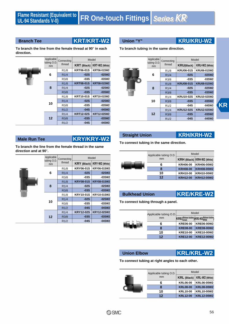
KR
FR One-touch FittingsFlame Resistant (Equivalent to UL-94 Standards V-0)
Branch Tee
6
8
10
12
KRT06-01S
-02S
-03S
KRT08-01S
-02S
-03S
KRT10-01S
-02S
-03S
-04S
KRT12-02S
-03S
-04S
KRT06-01SW2
-02SW2
-03SW2
KRT08-01SW2
-02SW2
-03SW2
KRT10-01SW2
-02SW2
-03SW2
-04SW2
KRT12-02SW2
-03SW2
-04SW2
To branch the line from the female thread at 90° in each direction.
Male Run Tee
To branch the line from the female thread in the same direction and at 90°.
Applicabletubing O.D.
mm
6
8
10
12
Connecting thread
Applicabletubing O.D.
mm
Connecting thread
Model
KRY06-01S
-02S
-03S
KRY08-01S
-02S
-03S
KRY10-01S
-02S
-03S
-04S
KRY12-02S
-03S
-04S
KRY06-01SW2
-02SW2
-03SW2
KRY08-01SW2
-02SW2
-03SW2
KRY10-01SW2
-02SW2
-03SW2
-04SW2
KRY12-02SW2
-03SW2
-04SW2
KRY/KRY-W2
KRT/KRT-W2
KRT (Black) KRT-W2 (White)
Union "Y"
To branch tubing in the same direction.
KRU/KRU-W2
Applicabletubing O.D.
mm
6
8
10
12
Connecting thread
KRU06-01S
-02S
-03S
KRU08-01S
-02S
-03S
KRU10-02S
-03S
-04S
KRU12-02S
-03S
-04S
KRU06-01SW2
-02SW2
-03SW2
KRU08-01SW2
-02SW2
-03SW2
KRU10-02SW2
-03SW2
-04SW2
KRU12-02SW2
-03SW2
-04SW2
Model
KRY (Black) KRY-W2 (White)
Model
KRU(Black) KRU-W2 (White)
Straight Union
To connect tubing in the same direction.
KRH/KRH-W2
Applicable tubing O.D.mm
68
1012
KRH06-00
KRH08-00
KRH10-00
KRH12-00
KRH06-00W2
KRH08-00W2
KRH10-00W2
KRH12-00W2
Model
KRH (Black) KRH-W2 (White)
Bulkhead Union
To connect tubing through a panel.
KRE/KRE-W2
Applicable tubing O.D.mm
68
1012
KRE06-00
KRE08-00
KRE10-00
KRE12-00
KRE06-00W2
KRE08-00W2
KRE10-00W2
KRE12-00W2
Model
KRE( )KRE-W2( )
Union Elbow
To connect tubing at right angles to each other.
KRL/KRL-W2
Applicable tubing O.D.mm
68
1012
KRL06-00
KRL08-00
KRL10-00
KRL12-00
KRL06-00W2
KRL08-00W2
KRL10-00W2
KRL12-00W2
Model
KRL (Black) KRL-W2 (White)
R1/8
R1/4
R3/8
R1/8
R1/4
R3/8
R1/8
R1/4
R3/8
R1/2
R1/4
R3/8
R1/2
R1/8
R1/4
R3/8
R1/8
R1/4
R3/8
R1/4
R3/8
R1/2
R1/4
R3/8
R1/2
R1/8
R1/4
R3/8
R1/8
R1/4
R3/8
R1/8
R1/4
R3/8
R1/2
R1/4
R3/8
R1/2Release button,Green
Release buttonWhite
56

FR One-touch Fittings
Union Tee
681012
KRT06-00
KRT08-00
KRT10-00
KRT12-00
KRT06-00W2
KRT08-00W2
KRT10-00W2
KRT12-00W2
To branch tubing into 2 directions each at 90° to the original one.
Union "Y"
To branch tubing in the same direction.
Applicable tubing O.D.mm
681012
Applicable tubing O.D.mm
Model
KRU06-00
KRU08-00
KRU10-00
KRU12-00
KRU06-00W2
KRU08-00W2
KRU10-00W2
KRU12-00W2
KRU/KRU-W2
KRT/KRT-W2
KRT (Black) KRT-W2 (White)
Plug
To plug unused one-touch fittings.
KRP
68
1012
KRP-06
KRP-08
KRP-10
KRP-12
Model
KRU (Black) KRU-W2 (White)
Model
Plug-in Reducer
To connect to a smaller one-touch fitting.
KRR/KRR-W2
Applicabletubing O.D.
mm
Fitting size
Fitting size
6
8
10
810101212
KRR06-08
-10
KRR08-10
-12
KRR10-12
KRR06-08W2
-10W2
KRR08-10W2
-12W2
KRR10-12W2
Model
KRR (Black) KRR-W2 (White)
Plug-in "Y"
To branch the line from a one-touch fitting into tubing in the same direction.
KRU/KRU-W2
Applicabletubing O.D.
mm
Fitting size
681012
681012
KRU06-99
KRU08-99
KRU10-99
KRU12-99
KRU06-99W2
KRU08-99W2
KRU10-99W2
KRU12-99W2
Model
KRU (Black) KRU-W2 (White)
Spatter cover 1
Prevents releasing of the tubing due to spatter invasion or adhesion.KR (Applicable tubing: FR soft nylon)
KR
68
1012
KR-06C
KR-08C
KR-10C
KR-12C
ModelFitting size
Spatter cover 2
Prevents releasing of the tubing due to spatter invasion or adhesion.KR (Applicable tubing: FR soft nylon, FR2 layer)
KR
68
1012
KR-06C1
KR-08C1
KR-10C1
KR-12C1
ModelFitting size
Flame Resistant (Equivalent to UL-94 Standards V-0)
KR
57

KR
FR One-touch Fittings
Bulkhead Female Union
6
8
10
12
Used for trunk connection between tubing and a male thread installed through a panel.
Applicabletubing O.D.
mm
Model
KRE-W2
KRE-W2 (White)
KRE06-01W2
-02W2
-03W2
KRE08-01W2
-02W2
-03W2
KRE10-02W2
-03W2
KRE12-02W2
-03W2
-04W2
Connecting thread
Rc1/8
Rc1/4
Rc3/8
Rc1/8
Rc1/4
Rc3/8
Rc1/4
Rc3/8
Rc1/4
Rc3/8
Rc1/2
This model is not available with black body specifications.
Plug-in Elbow
To change the tubing direction from a one-touch fitting by 90°.
KRL-W2
Applicabletubing O.D.
mm
681012
681012
KRL06-99W2
KRL08-99W2
KRL10-99W2
KRL12-99W2
Model
KRL-W2 (White)
Extended Plug-in Elbow
To change the tubing direction from a one-touch fitting by 90°. Applicable to 3 dimensional piping when used with a plug-in elbow.
KRW-W2
Applicabletubing O.D.
mm
681012
Fitting size
Fitting size
681012
KRW06-99W2
KRW08-99W2
KRW10-99W2
KRW12-99W2
Model
KRW-W2 (White)
This model is not available with black body specifications.
This model is not available with black body specifications.
Flame Resistant (Equivalent to UL-94 Standards V-0)
Made to OrderOrderMade
Electroless Nickel Plated on Brass Parts
(Example) KRH06-02S-X2
X2
58

Applicable tubing O.D.: Metric SizeConnecting thread: Rc
FR One-touch Fittings Manifold
Model
Fluid
Max. operating pressure
Proof pressure
Ambient and fluid temperature
Thread
Accessory
Air, Water Note 1)
1.0MPa
3.0MPa
–5 to 60°C,In case of water: 0 to 60 °C (With no condensation)
Note 1) Applicable to general industrial water. Consult SMC if using for other fluids. Surge pressure must be under the maximum operating pressure.
Tubing material
Tubing O.D.
FR double layer, FR soft nylon
ø6, ø8, ø10, ø12
Applicable Tubing
Model
Specifications
Construction
KRM11 KRM12
KRM11
KRM12
Compact piping possible.
Manifold piping possible.
Rich variation of 8 styles.
One-touch installation.
Cover (Option).
Port AConnection size
Number of port A
Porting
Port A Port BModel
KRM11
KRM12
One-touch fitting
One-touch fitting
One-touch fitting
Rc female thread
6, 10
6, 10
ø6 tubing
ø8 tubing
ø6 tubing
ø8 tubing
Port BConnection size
ø10 tubing
ø12 tubing
Rc1/4
Rc3/8
JIS B0203 (Taper thread for piping)
Hexagon socket head plug: 1 pc
—
None
KRM12KRM11
Flame Resistant (Equivalent to UL-94 Standards V-0)
Spatter Proof
59

KRM
6
A
8
10
B
12
6
10
6
10
KRM11-06-10-6
-10
KRM11-08-12-6
-10
Connectionthread
Applicable tubing O.D. mm Numberof port A
Model
KRM11
A
B
6
8
6
10
6
10
KRMC-06-6
-10
KRMC-08-6
-10
Applicable tubing O.D.
mmN Model
6
8
6
10
6
10
KRM12-06-02-6
-10
KRM12-08-03-6
-10
Applicable tubing O.D.
mm
Numberof port A
Model
KRM12
A
A
Refer to KR- and page 57 for spatter covers 1 and 2.
Spatter Cover 3 KRMC
FR One-touch Fittings ManifoldFlame Resistant (Equivalent to UL-94 Standards V-0)
Rc1/4
Rc3/8
KRMC (Applicable tubing: FR soft nylon)
Made to OrderOrderMade
Electroless Nickel Plated on Brass Parts
(Example) KRM11-06-10-6-X2
X2
60

Connection type: R, Rc, One-touch FittingNut Fittings
S Coupler
PAT.
Fluid
Operating pressure range
Proof pressure
Ambient and fluid temperature
Plating, Seal
Air, Water (General industrial water)
0 to 1.0MPa
1.5MPa
Air: –5 to 60°C Water: 5 to 40°C
With electroless nickel plated (For copper free application), With male thread seal
Specifications
Plug and socket connection
Check valve
Sleeve lock mechanism
One-touch attachment and removal
Socket: Built-in check valve (Standard)
Manual locking type (Standard)
Performance
Body size
1/8
1/4
1/2
Plug
KK3P-01MS
KK4P-02MS
KK6P-04MS
Socket
KK3S-01MS
KK4S-02MS
KK6S-04MS
Effective area mm2
20
39
82
Effective Area
PAT.
Light weightNot only the body is miniaturized but the weight is also reduced to the minimum by adoption of pressed parts and resin parts.
Adoption of a unique connection methodBy eliminating the use of steel balls, a large effective sectoinal area is achieved on a compact body without constricting the passage.
No spring is installed in the passageMore effective sectional area is available because there are no valve springs blocking the passage.
The end of the check valve is shaped for a larger rectification effectAchieves a smooth fluid flow.
0.1
Pressure (MPa)
Flo
w r
ate
(l/m
in(A
NR
))
0.20 0.3 0.4 0.5 0.6 0.7 0.8 0.9 1
1,000
2,000
0
3,000
4,000
5,000
6,000
7,000
8,000
9,000
10,000
11,000
KK3 series(KK3S-01MS+KK3P-01MS)
KK4 series(KK4S-02MS—KK4P-02MS)
KK6 series(KK6S-04MS+KK6P-04MS)
Flow Characteristics
Large effective sectional area.Light weight.
JIS symbol
Plug single Socket single
Plug and socket connection
61

KK
S Coupler
Male Thread Type
1/8
1/4
1/2
KK3P-01MS
-02MS
KK4P-01MS
-02MS
-03MS
-04MS
KK6P-03MS
-04MS
-06MS
ModelBody size Port size
Male Thread Type
Plug (P) Socket (S)
1/8
1/4
1/2
KK3S-01MS
-02MS
KK4S-01MS
-02MS
-03MS
-04MS
KK6S-03MS
-04MS
-06MS
ModelBody size Port size
Nut Fitting Type (for fiber reinforced urethane hose)
1/8
1/4
1/2
KK3P-50N
-60N
-65N
KK4P-50N
-60N
-65N
-80N
-85N
KK6P-80N
-85N
-110N
5/8
6/9
6.5/10
5/8
6/9
6.5/10
8/12
8.5/12.5
8/12
8.5/12.5
11/16
ModelBody sizeApplicable hose I.D. / O.D. mm
1/8
1/4
1/2
KK3S-50N
-60N
-65N
KK4S-50N
-60N
-65N
-80N
-85N
KK6S-80N
-85N
-110N
ModelBody sizeApplicable hose I.D. / O.D. mm
Female Thread Type
1/8
1/4
1/2
KK3P-01F
KK4P-02F
-03F
KK6P-03F
-04F
ModelBody size Port size
Female Thread Type
1/8
1/4
1/2
KK3S-01F
KK4S-02F
-03F
KK6S-03F
-04F
ModelBody size Port size
Nut Fitting Type (for fiber reinforced urethane hose)
R1/8
R1/4
R1/8
R1/4
R3/8
R1/2
R3/8
R1/2
R3/4
Rc1/8
Rc1/4
Rc3/8
Rc3/8
Rc1/2
Rc1/8
Rc1/4
Rc3/8
Rc3/8
Rc1/2
R1/8
R1/4
R1/8
R1/4
R3/8
R1/2
R3/8
R1/2
R3/4
5/8
6/9
6.5/10
5/8
6/9
6.5/10
8/12
8.5/12.5
8/12
8.5/12.5
11/16
62

S Coupler
Straight Type with One-touch Fitting
1/8
1/4
1/2
4
6
8
10
6
8
10
12
12
16
KK3P-04H
-06H
-08H
-10H
KK4P-06H
-08H
-10H
-12H
KK6P-12H
-16H
ModelBody sizeApplicabletubing O.D.
mm
Plug (P) Socket (S)
Straight Type with One-touch Fitting
1/8
1/4
1/2
4
6
8
10
6
8
10
12
12
16
KK3S-04H
-06H
-08H
-10H
KK4S-06H
-08H
-10H
-12H
KK6S-12H
-16H
ModelBody sizeApplicabletubing O.D.
mm
Elbow Type with One-touch Fitting
1/8
1/4
1/2
4
6
8
10
6
8
10
12
12
16
KK3P-04L
-06L
-08L
-10L
KK4P-06L
-08L
-10L
-12L
KK6P-12L
-16L
ModelBody sizeApplicabletubing O.D.
mm
Elbow Type with One-touch Fitting
1/8
1/4
1/2
4
6
8
10
6
8
10
12
12
16
KK3S-04L
-06L
-08L
-10L
KK4S-06L
-08L
-10L
-12L
KK6S-12L
-16L
ModelBody sizeApplicabletubing O.D.
mm
Bulkhead Type with One-touch Fitting
1/8
1/4
1/2
4
6
8
10
6
8
10
12
12
16
KK3P-04E
-06E
-08E
-10E
KK4P-06E
-08E
-10E
-12E
KK6P-12E
-16E
ModelBody sizeApplicabletubing O.D.
mm
Bulkhead Type with One-touch Fitting
1/8
1/4
1/2
4
6
8
10
6
8
10
12
12
16
KK3S-04E
-06E
-08E
-10E
KK4S-06E
-08E
-10E
-12E
KK6S-12E
-16E
ModelBody sizeApplicabletubing O.D.
mm
63

KKH
Connection type:R, Rc, Nut Fittings
S Coupler
PAT.
Fluid
Operating pressure range
Proof pressure
Ambient and fluid temperature
Plating, Seal
Connection plug
Air, Water (General industrial water)
0 to 1.0 MPa
1.5MPa
Air: –5 to 60°C Water: 5 to 40°C
Electroless nickel plated, With male thread seal
Series KK plug
Plug and socket connection
Check valve
Sleeve lock mechanism
One-touch attachment and removal
Socket: Built-in check valve
—
Performance
Body size
1/8
1/4
Plug
KK3P-01MS
KK4P-02MS
Socket
KKH3S-01MS
KKH4S-02MS
Effective area mm2
20
39
Effective Area
PAT.
The flow rate is same as that of current standard products because common internal parts are used.
Cover ring(Super high impact PBT)(High impact PBT)
(Rubber)
Spacer
Sleeve cover
SpecificationsRubber cover and super-high-impact PBT resin which absorb drop impact (Equivalent to impact energy of 0.5J) are adopted for body peripheral materials.Same flow rate as that of conventional series (Series KK).
JIS symbol
Plug single Socket single
Plug and socket connection
64

S Coupler
Male Thread Type
1/8
1/4
KK3P-01MS
-02MS
KK4P-01MS
-02MS
-03MS
-04MS
ModelBody size Port size
Plug (P) Socket (S)
1/8
1/4
KK3P-50N
-60N
-65N
KK4P-50N
-60N
-65N
-80N
-85N
ModelBody size
Female Thread Type
1/8
1/4
KK3P-01F
KK4P-02F
-03F
ModelBody size Port size
Nut Fitting Type (for fiber reinforced urethane hose)
Applicable hose I.D. / O.D. mm
Male Thread Type
1/8
1/4
KKH3S-01MS
-02MS
KKH4S-01MS
-02MS
-03MS
-04MS
ModelBody size Port size
1/8
1/4
KKH3S-50N
-60N
-65N
KKH4S-50N
-60N
-65N
-80N
-85N
ModelBody size
Female Thread Type
1/8
1/4
KKH3S-01F
KKH4S-02F
-03F
ModelBody size Port size
Nut Fitting Type (for fiber reinforced urethane hose)
Applicable hose I.D. / O.D. mm
R1/8
R1/4
R3/8
R1/8
R1/4
R3/8
R1/8
R1/4
R1/8
R1/4
R3/8
R1/2
R1/8
R1/4
R1/8
R1/4
R3/8
R1/2
Only sockets are provided as series KKH.
Please use plugs in Series KK.
5/8
6/9
6.5/10
5/8
6/9
6.5/10
8/12
8.5/12.5
5/8
6/9
6.5/10
5/8
6/9
6.5/10
8/12
8.5/12.5
65
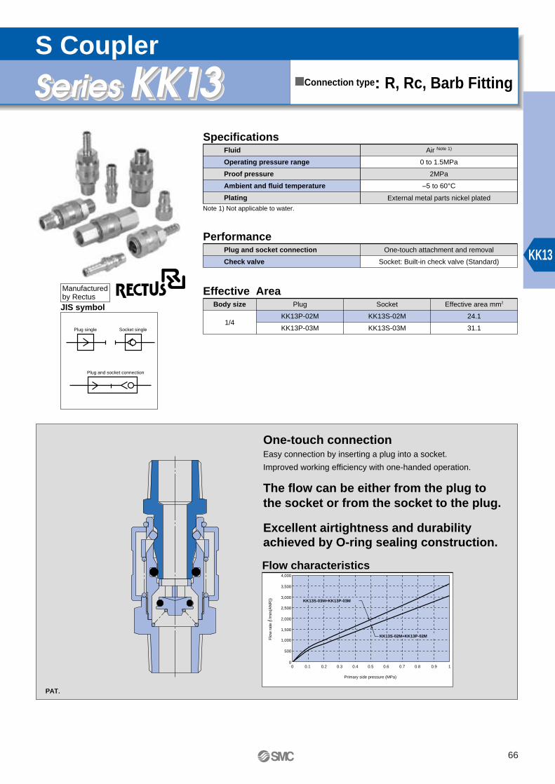
KK13
Connection type: R, Rc, Barb Fitting
S Coupler
PAT.
Fluid
Operating pressure range
Proof pressure
Ambient and fluid temperature
Plating
Air Note 1)
0 to 1.5MPa
2MPa
–5 to 60°C
External metal parts nickel plated
Specifications
Plug and socket connection
Check valve
One-touch attachment and removal
Socket: Built-in check valve (Standard)
Performance
PAT.
Note 1) Not applicable to water.
Body size Plug
KK13P-02M
KK13P-03M
Socket
KK13S-02M
KK13S-03M
Effective area mm2
24.1
31.1
Effective Area
1/4
One-touch connectionEasy connection by inserting a plug into a socket.
Improved working efficiency with one-handed operation.
The flow can be either from the plug to the socket or from the socket to the plug.
Excellent airtightness and durability achieved by O-ring sealing construction.
0.1
Primary side pressure (MPa)
Flo
w r
ate
(l/m
in(A
NR
))
0.20 0.3 0.4 0.5 0.6 0.7 0.8 0.9 1
500
0
1,000
1,500
2,500
3,500
3,000
4,000
2,000
KK13S-03M+KK13P-03M
KK13S-02M+KK13P-02M
Flow characteristics
JIS symbol
Plug single Socket single
Plug and socket connection
Manufactured by Rectus
66

S Coupler
Male Thread Type
KK13P-01M
-02M
-03M
-04M
ModelPort size
KK13S-01M
-02M
-03M
-04M
Model
Plug (P) Socket (S)
Male Thread Type
Female Thread Type
KK13P-02F
-03F
-04F
-G02F
ModelPort size
KK13S-02F
-03F
-04F
ModelPort size
Port size
Female Thread Type
Barb Fitting Type
1/4"
5/16"
3/8"
1/2"
KK13P-07B
-09B
-11B
-13B
ModelApplicable hose I.D.
1/4"
5/16"
3/8"
1/2"
KK13S-07B
-09B
-11B
-13B
ModelApplicable hose I.D.
Barb Fitting Type
Nut Fitting Type Nut Fitting Type
R1/8
R1/4
R3/8
R1/2
R1/4
R3/8
R1/2
R1/4
R1/4
R3/8
R1/2
R1/8
R1/4
R3/8
R1/2
KK13P-50N
-60N
-65N
-80N
-85N
-110N
ModelApplicable hose I.D. / O.D. mm
KK13S-50N
-60N
-65N
-80N
-85N
-110N
ModelApplicable hose I.D. / O.D. mm
5/8
6/9
6.5/10
8/12
8.5/12.5
11/16
5/8
6/9
6.5/10
8/12
8.5/12.5
11/16
67

KF
Applicable tubing O.D.: Metric SizeConnecting thread: R, Rc
Insert Fittings
PAT.
Fluid
Max. operating pressure
Operating vacuum pressure
Pressure
Ambient and fluid temperature
Sealant (Thread portion) Note)
Air
1.0MPa
–101.3kPa
7.0MPa
–5 to 60°C (With no condensation)
JIS B0203 (Taper thread for piping)
JIS B0211, Class 2 (Metric fine thread)
None or with sealant
Tubing size
Note) Since polyurethane tubing of sizes ø8, ø10 and ø12, which are marked with , have different inside diameters, they must be used with special models.
Note) The male elbow, male branch tee and male run tee with sealant are manufactured upon receipt of order.
Material
O.D.
I.D.
4
2.5
6
4
8
5
—
—
Note
6
—
10
6.5
—
—
Note
7.5
—
12
8
—
—
Note
9
—
Nylon tubing
Soft nylon tubing
Polyurethane tubing
Applicable Tubing
Specifications
Thread portion
Nut partThread
Body
Nut
Ferrule
C3604BD, C3771BE
C3604BD
Nylon 66
Main Parts Material
Applicable to nylon, soft nylon and polyurethane tubing.
Designed to allow small tightening torque to improve working efficiency.
InsertApplicable to nylon and polyurethane.Large retaining force.Tubing is securely held from inside and outside by the insert mechanism.
Prevents tubing sliding during installation.The tubing holding mechanism gives the strong feeling when inserting the tubing and prevents the tubing from sliding when screwing in the tubing.
Tubing holder
Prevents the ferrule nut from sliding off along the tubing.The tubing grip lightly holds the tubing.
Tubing grip
Body
Tubing
Small tightening torque.Adoption of the resin ferrule increases efficiency in tightening work.Compatible with of -101.3kPa to 1.0MPa
Ferrule
Union nut
68

Insert Fittings
Male Connector
4
6
2.5
4
5
6
6.5
7.5
8
9
8
10
12
KFH04-01
-02
KFH06-01
-02
-03
KFH08U-01
-02
-03
KFH08N-01
-02
-03
KFH10U-02
-03
-04
KFH10N-02
-03
-04
KFH12U-02
-03
-04
KFH12N-02
-03
-04
Most common style used to pipe from female thread in the same direction.
Applicable tubing mm
O.D. I.D.
Connecting thread
Model
KFH Swivel Elbow
4
6
2.5
4
5
6
6.5
7.5
8
9
8
10
12
KFV04-01
-02
KFV06-01
-02
-03
KFV08U-01
-02
-03
KFV08N-01
-02
-03
KFV10U-02
-03
-04
KFV10N-02
-03
-04
KFV12U-02
-03
-04
KFV12N-02
-03
-04
To pipe from the female threaded at the right angle.Swiveled at any direction.
Applicable tubing mm Connecting
threadModel
KFV
Male Elbow
4
6
2.5
4
5
6
6.5
7.5
8
9
8
10
12
KFL04-01
-02
KFL06-01
-02
-03
KFL08U-01
-02
-03
KFL08N-01
-02
-03
KFL10U-02
-03
-04
KFL10N-02
-03
-04
KFL12U-02
-03
-04
KFL12N-02
-03
-04
Most common style used to pipe from female thread at a right angle.
Applicable tubing mm Connecting
threadModel
KFL Swivel Extended Elbow
4
6
2.5
4
5
6
6.5
7.5
8
9
8
10
12
KFW04-01
-02
KFW06-01
-02
-03
KFW08U-01
-02
-03
KFW08N-01
-02
-03
KFW10U-02
-03
-04
KFW10N-02
-03
-04
KFW12U-02
-03
-04
KFW12N-02
-03
-04
To pipe from the female threaded at a right angle.Swiveled at any direction. Solid piece moves fittings up from work piece.
Applicabletubing mm Connecting
threadModel
KFW
R1/8
R1/4
R1/8
R1/4
R3/8
R1/8
R1/4
R3/8
R1/8
R1/4
R3/8
R1/4
R3/8
R1/2
R1/4
R3/8
R1/2
R1/4
R3/8
R1/2
R1/4
R3/8
R1/2
R1/8
R1/4
R1/8
R1/4
R3/8
R1/8
R1/4
R3/8
R1/8
R1/4
R3/8
R1/4
R3/8
R1/2
R1/4
R3/8
R1/2
R1/4
R3/8
R1/2
R1/4
R3/8
R1/2
R1/8
R1/4
R1/8
R1/4
R3/8
R1/8
R1/4
R3/8
R1/8
R1/4
R3/8
R1/4
R3/8
R1/2
R1/4
R3/8
R1/2
R1/4
R3/8
R1/2
R1/4
R3/8
R1/2
R1/8
R1/4
R1/8
R1/4
R3/8
R1/8
R1/4
R3/8
R1/8
R1/4
R3/8
R1/4
R3/8
R1/2
R1/4
R3/8
R1/2
R1/4
R3/8
R1/2
R1/4
R3/8
R1/2
O.D. I.D.
O.D. I.D.O.D. I.D.
69

KF
Insert Fittings
Male Branch Tee
4
6
2.5
4
5
6
6.5
7.5
8
9
8
10
12
KFT04-01
-02
KFT06-01
-02
-03
KFT08U-01
-02
-03
KFT08N-01
-02
-03
KFT10U-02
-03
-04
KFT10N-02
-03
-04
KFT12U-02
-03
-04
KFT12N-02
-03
-04
To branch the line from the female thread at 90° in each direction.
Applicable tubing mmO.D. I.D.
Connecting thread
Model
KFT Straight Union
46
2.5456
6.57.589
8
10
12
KFH04-00
KFH06-00
KFH08U-00
KFH08N-00
KFH10U-00
KFH10N-00
KFH12U-00
KFH12N-00
To connect tubing in the same direction.
Applicable tubingmm
O.D. I.D.Model
KFH
Male Run Tee
4
6
2.5
4
5
6
6.5
7.5
8
9
8
10
12
KFY04-01
-02
KFY06-01
-02
-03
KFY08U-01
-02
-03
KFY08N-01
-02
-03
KFY10U-02
-03
-04
KFY10N-02
-03
-04
KFY12U-02
-03
-04
KFY12N-02
-03
-04
To branch the line from the female thread in the same direction and at 90°.
Applicable tubing mmO.D. I.D.
Connecting thread
Model
KFY
Bulkhead Connector
6 456
6.57.589
8
10
12
KFE06-02
KFE08U-03
KFE08N-03
KFE10U-03
KFE10N-03
KFE12U-03
KFE12N-03
Applicable tubing mmO.D. I.D.
Model
KFE
Bulkhead Union
46
2.5456
6.57.589
8
10
12
KFE04-00
KFE06-00
KFE08U-00
KFE08N-00
KFE10U-00
KFE10N-00
KFE12U-00
KFE12N-00
To connect tubing through a panel.
Used for trunk connection between tubing and a male thread installed on a panel.
O.D. I.D.Model
KFE
Connecting thread
R1/8
R1/4
R1/8
R1/4
R3/8
R1/8
R1/4
R3/8
R1/8
R1/4
R3/8
R1/4
R3/8
R1/2
R1/4
R3/8
R1/2
R1/4
R3/8
R1/2
R1/4
R3/8
R1/2
R1/8
R1/4
R1/8
R1/4
R3/8
R1/8
R1/4
R3/8
R1/8
R1/4
R3/8
R1/4
R3/8
R1/2
R1/4
R3/8
R1/2
R1/4
R3/8
R1/2
R1/4
R3/8
R1/2
Rc1/4
Rc3/8
Rc3/8
Rc3/8
Applicable tubingmm
70

Insert Fittings
Plug
468
1012
KFP-04
KFP-06
KFP-08
KFP-10
KFP-12
To plug unused insert fittings.
Applicable tubingmm
Model
KFPUnion Tee
46
2.5456
6.57.589
8
10
12
KFT04-00
KFT06-00
KFT08U-00
KFT08N-00
KFT10U-00
KFT10N-00
KFT12U-00
KFT12N-00
To branch tubing into 2 directions each at 90° to the original one.
Applicable tubingmm
O.D. I.D.Model
KFT
Female Connector
4
6
2.5
4
56
6.57.589
8
10
12
KFF04-02
KFF06-02
-03
KFF08U-02
KFF08N-02
KFF10U-02
KFF10N-02
KFF12U-02
KFF12N-02
To pipe from the male threaded portion of a pressure gauge, etc.
Applicable tubing mm
O.D. I.D.Model
KFF
Connecting thread
Made to OrderOrderMade
Electroless Nickel Plated Metal Parts
(Example) KFH06-02-X2
X2 With Sealant on R Thread
(Example) KFH06-02S
SClean Series
Electroless nickel plated metal parts (X2).Double packaging.
(Example) 10-KFH06-02
10-
Rc1/4
Rc1/4
Rc3/8
Rc1/4
Rc1/4
Rc1/4
71

H,DLL,LL
Applicable tubing O.D.: Metric SizeConnecting thread: R, Rc
Self-align Fittings
Applicable tubing material
Applicable tubing O.D.
Max. operating pressure
Proof pressure
Fluid
Sealant (Thread portion) Note)
Nylon tubing, Soft nylon tubing, Soft copper tubing (C1220T-O)
ø4, ø6, ø8, ø10, ø12
1.0MPa
10MPa
Air
JIS B 0203 (Taper thread for piping)
JIS B 0211 Class 2 (Metric fine thread)
None or with sealant
Thread portion
Nut part
Body
Nut
Ferrule
C3604BD, C3771BE
C3604BD
C2700T
Main Parts Material
Specifications
Thread
Ferrule with no orientation.The non-oriented construction is free from mistakes and consequent working loss or accidents when inserting the ferrule into the fitting body.
Hardened ridge ferrule.The single bite construction with a strong ridge prevents breakage of ferrule when tightening.
Small pressure loss.A large flow rate is achieved with small flow resistance due to the construction without an insert.
Wide variety of styles and sizes.10 models including swivel styles and 5 tubing O.D. provide a wide range of fittings that will fit any application.
Note) The male elbow, male branch tee and service tee union with sealant are manufactured upon receipt of order.
Prevents tubing from deforming inwards.
Prevents tubing sliding during installation.The tubing holding mechanism gives the strong feeling when inserting the tubing and prevents the tubing from sliding when screwing in the tubing.
Flared inside diameter
Tubing holder
Large holding force by metal ferrule.Applicable to soft copper.(Not applicable to urethane tubing.)
Ferrule
Body
Union nut
Tubing
PAT.
Spatter Proof
72

Self-align Fittings
Male Connector
4
6
8
10
12
H04-01
-02
H06-01
-02
-03
H08-01
-02
-03
H10-02
-03
-04
H12-02
-03
-04
Most common style used to pipe from female thread in the same direction.
Applicable tubingmm
Connecting thread
Model
H Swivel Elbow
4
6
8
10
12
L04-01
-02
L06-01
-02
-03
L08-01
-02
-03
L10-02
-03
-04
L12-02
-03
-04
To pipe from the female threaded at the right angle.Swiveled at any direction.
L
Male Elbow
4
6
8
10
12
DL04-01
-02
DL06-01
-02
-03
DL08-01
-02
-03
DL10-02
-03
-04
DL12-02
-03
-04
Most common style used to pipe from female thread at a right angle.
DL Swivel Extended Elbow
4
6
8
10
12
LL04-01
-02
LL06-01
-02
-03
LL08-01
-02
-03
LL10-02
-03
-04
LL12-02
-03
-04
To pipe from the female threaded at a right angle.Swiveled at any direction. Solid piece moves fittings up from work piece.
LL
R1/8
R1/4
R1/8
R1/4
R3/8
R1/8
R1/4
R3/8
R1/4
R3/8
R1/2
R1/4
R3/8
R1/2
R1/8
R1/4
R1/8
R1/4
R3/8
R1/8
R1/4
R3/8
R1/4
R3/8
R1/2
R1/4
R3/8
R1/2
R1/8
R1/4
R1/8
R1/4
R3/8
R1/8
R1/4
R3/8
R1/4
R3/8
R1/2
R1/4
R3/8
R1/2
R1/8
R1/4
R1/8
R1/4
R3/8
R1/8
R1/4
R3/8
R1/4
R3/8
R1/2
R1/4
R3/8
R1/2
Applicable tubingmm
Connecting thread Model
Applicable tubingmm
Connecting thread Model
Applicable tubingmm
Connecting thread
Model
73

H,DLL,LL
Self-align Fittings
Male Branch Tee
4
6
8
10
12
DT04-01
-02
DT06-01
-02
-03
DT08-01
-02
-03
DT10-02
-03
-04
DT12-02
-03
-04
To branch the line from the female thread at 90° in each direction.
DT
Male Run Tee
4
6
8
10
12
DY04-01
-02
DY06-01
-02
-03
DY08-01
-02
-03
DY10-02
-03
-04
DY12-02
-03
-04
To branch the line from the female thread in the same direction and at 90°.
DY
Bulkhead Union
4681012
DE04-00
DE06-00
DE08-00
DE10-00
DE12-00
To connect tubing through a panel.
DE
Union Tee
468
1012
DT04-00
DT06-00
DT08-00
DT10-00
DT12-00
To branch tubing into 2 directions each at 90° to the original one.
DT
Female Connector
4
6
81012
DHF04-02
DHF06-02
-03
DHF08-02
DHF10-02
DHF12-02
To pipe from the male threaded portion of a pressure gauge, etc.
DHF
Bulkhead Female Connector
68
1012
DEF06-02
DEF08-03
DEF10-03
DEF12-03
Used for trunk connection between tubing and a male thread installed through a panel.
DEF
Plug
ø4ø6ø8
ø10ø12
DP-04
DP-06
DP-08
DP-10
DP-12
To plug unused self-align fittings.
Applicable fitting size
Model
DP
R1/8
R1/4
R1/8
R1/4
R3/8
R1/8
R1/4
R3/8
R1/4
R3/8
R1/2
R1/4
R3/8
R1/2
R1/8
R1/4
R1/8
R1/4
R3/8
R1/8
R1/4
R3/8
R1/4
R3/8
R1/2
R1/4
R3/8
R1/2
Rc1/4
Rc3/8
Rc3/8
Rc3/8
Rc1/4
Rc1/4
Rc3/8
Rc1/4
Rc1/4
Rc1/4
Applicable tubing
mm
Connecting thread Model
Applicable tubing
mm
Connecting thread Model
Applicable tubing mm
Model
Applicable tubing
mm
Connecting thread Model
Applicable tubing
mm
Connecting thread Model
Applicable tubing mm Model
74

Made to OrderOrderMade
Electroless Nickel Plated Metal Parts
(Example) H06-02-X2
X2 With Sealant on R Thread
(Example) H06-02S
S
75

Applicable tubing O.D.: Metric SizeConnecting thread: M3, M5, R1/8
Miniature Fittings
Applicable tubing material
Max. operating pressure (at 20°C)
Connection size
Thread
Specifications
Hose Nipple
Barb Fittings
Compact piping space.The hose nipple has a large holding force, allowing easy connection and removal.
A wide variety of models is available.Piping in the same direction is possible at different heights.
Hose nipple, Hose elbow.Hose nipples and hose elbow accept nylon, soft nylon and polyurethane tubing.
Nylon Soft nylon
M3, M5, R1/8
1.0MPa
JIS B0209 Class 2 (Metric thread), JIS B0203 (Taper thread for piping)
Polyurethane
ø4/ø2.5ø6/ø4
ø3.18/ø2.18 ø4/ø2.5ø6/ø4
ø3.18/ø2ø4/ø2.5, ø6/ø4
1.5MPa 0.8MPa
Tubing
Barb fittingsThe tube allows easy tubing insertion as well as secure tubing holding.
BodyWith electroless nickel plated
BodyWith electroless nickel plated
Hose nipples and hose elbow accept nylon, soft nylon and polyurethane tubing.
Cap nutSecure holding is achieved by manual tightening.Easy disconnection of tubing by loosening.Electroless nickel plated.
GasketSmall tightening torque.Secure sealing.
Barb fittingsThe tube allows easy tubing insertion as well as secure tubing holding.
GasketSmall tightening torque.Secure sealing.
Tubing
M
—M3
M5-R1/8
ø4/ø2.5 ø3.18/ø2, ø4/ø2.5
PAT.
Applicabletubing
76
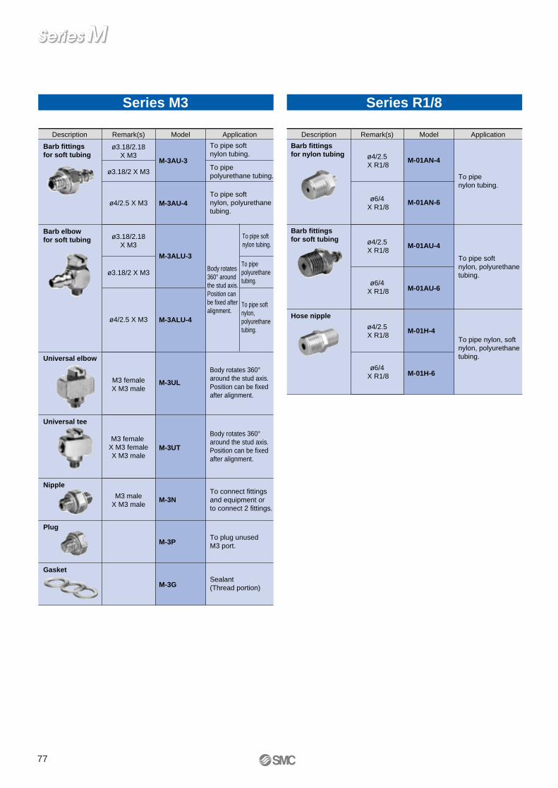
ModelDescription
Barb fittings for soft tubing
To pipe soft nylon tubing.
Application
To pipepolyurethane tubing.
To pipe soft nylon, polyurethane tubing.
M-3AU-3
M-3AU-4
Barb elbow for soft tubing
Universal elbow
To pipe soft nylon tubing.
To pipepolyurethane tubing.
To pipe soft nylon,polyurethane tubing.
M-3ALU-3
M-3ALU-4
Body rotates 360° around the stud axis. Position can be fixed after alignment.
Body rotates 360° around the stud axis. Position can be fixed after alignment.
M-3UL
Universal tee
ModelDescription ApplicationRemark(s)
ø3.18/2.18X M3
ø3.18/2 X M3
ø4/2.5 X M3
ø3.18/2.18X M3
ø3.18/2 X M3
ø4/2.5 X M3
M3 femaleX M3 male
M3 maleX M3 male
M3 female X M3 femaleX M3 male
M-3UT
NippleTo connect fittings and equipment or to connect 2 fittings.
M-3N
PlugTo plug unused M3 port.M-3P
GasketSealant (Thread portion)M-3G
M-01H-6
Hose nipple
To pipe nylon, soft nylon, polyurethane tubing.
M-01H-4
M-01AU-6
Barb fittings for soft tubing
To pipe soft nylon, polyurethane tubing.
M-01AU-4
Barb fittings for nylon tubing
To pipe nylon tubing.
M-01AN-4
Remark(s)
ø4/2.5 X R1/8
M-01AN-6ø6/4 X R1/8
ø4/2.5 X R1/8
ø6/4 X R1/8
ø4/2.5 X R1/8
ø6/4 X R1/8
Series M3 Series R1/8
Body rotates 360° around the stud axis. Position can be fixed after alignment.
77

M
ModelDescription
Barb fittings for nylon tubing
To pipe nylon tubing.
Application
M-5AN-4
M-5AN-6
Extension fitting For 3D piping to
prevent interference between fittings.
M-5J
Barb fittings for soft tubing
Barb elbow for nylon tubing
To pipe soft nylon tubing.
To pipepolyurethane tubing.
To pipe soft nylon tubing.
To pipepolyurethane tubing.
To pipe soft nylon, polyurethane tubing.
M-5AU-3
M-5AU-4
M-5AU-6
• To pipe nylon tubing• Body rotates 360°
around the stud axis. Position can be fixed after alignment.
M-5ALN-4
M-5ALN-6
Barb elbow for soft tubing
ModelDescription Application
To pipe soft nylon,polyurethane tubing.
Body rotates 360° around the stud axis. Position can be fixed after alignment.
To pipe soft nylon tubing.
To pipepolyurethane tubing.
To pipe soft nylon,polyurethane tubing.
Body rotates 360° around the stud axis. Position can be fixed after alignment.
Remark(s)
ø6/4 X M5
ø4/2.5 X M5ø4/2.5 X M5
ø3.18/2.18 X M5
ø3.18/2 X M5
ø3.18/2 X M5
ø4/2.5 X M5
ø6/4 X M5
ø4/2.5 X M5
ø6/4 X M5
ø3.18/2.18 X M5
ø6/4 X M5
ø4/2.5 X M5
M-5ALU-3
Barb elbow for nylon tubing (H)
Barb elbow for soft tubing (H)
• To pipe nylon tubing• Body rotates 360°
around the stud axis. Position can be fixed after alignment.
M-5ALHN-4
ø6/4 X M5 M-5ALHN-6
NippleTo connect fittings and equipment or to connect 2 fittings.
M-5N
Universal tee
M-5UT
Universal elbowBody rotates 360° around the stud axis. Position can be fixed after alignment.
Body rotates 360° around the stud axis. Position can be fixed after alignment.
M-5UL
TeePerpendicular piping in both directions.M-5T
Elbow
Perpendicular piping.M-5L
Hose elbow(H)
Hose elbow• To pipe nylon, soft
nylon, polyurethane tubing.
• Body rotates 360° around the stud axis. Position can be fixed after alignment.
Hose nipple To pipe nylon, soft nylon, polyurethane tubing.
M-5H-4
ø6/4 X M5 M-5H-6
ø4/2.5 X M5 M-5HL-4
ø6/4 X M5 M-5HL-6
ø4/2.5 X M5 M-5HLH-4
ø6/4 X M5 M-5HLH-6
M-5ALU-6
ø4/2.5 X M5 M-5ALU-4
ø3.18/2 X M5
ø3.18/2.18 X M5
ø6/4 X M5
M-5ALHU-3
ø4/2.5 X M5 M-5ALHU-4
M-5ALHU-6
Remark(s)
M5 female X M5 female X M5 male
M5 male X M5 female
M5 male X M5 male
Universal nipple
Body rotates 360° around the stud axis.M-5UN
M5 male X M5 male
PAT.
Bulkhead union
Panel mount connection
M-5EM5 X M5female – female
Bulkhead Reducer Reduction from Rc1/8 to M5. Panel mounting is possible.
M-5ERRc1/8 X M5 female
M5 female X M5 female X M5 female
M5 female X M5 male
M5 female X M5 female
Series M5
Manifold Rc1/8 can be diverted in up to nine M5 stations. Panel mounting is possible.
M-5MRc1/8
X M5 female(9 port )
Miniature Fittings
78

ModelDescription Application
Gasket (H) M-5AL-6M-5ALH-6M-5HL-4, 6M-5HLH-4, 6.
M-5GH
Gasket
PlugTo plug unused M5 port.
M5 thread label
Bushing
M-5B
M-5P
Material: PVC
Material:Nylon66GF30%
M-5G1
Remark(s)
Connection from R1/8 piping to M5 fittings.
R1/8 X M5 female
Series M5
Made to OrderOrderMade
Clean Series
Lubricant: Fluororesin grease (Fot only M-5UN)Double packaging
(Example) 10-M-5AN-4
10- Electroless Nickel Plated Metal Parts
M-5E-X2M-5ER-X2M-5M-X2Only the above three types are applicable. For other types, electroless nickel plating is standardized.
X2
79

Applicable tubing O.D.: Metric SizeConnecting thread: M5
Stainless Steel Series Miniature Fittings
Applicable tubing material
Applicable tubing diameter
Max. operating pressure (At 20°C)
Connection size
Material
Specifications
Hose Nipple
Barb Fittings
Can be used in corrosive applications.Stainless steel material (SUS316).Compact piping space.The hose nipple has a large holding force, allowing easy connection and removal.
A wide variety of models is available.Piping in the same direction is possible at different heights.
Hose Nipple, Hose elbow.Hose nipples and hose elbow accept nylon, soft nylon and polyurethane tubing.
Nylon Soft nylon
M5(JIS B0209, Class 2: Metric coarse thread)
1.0MPa
SUS316
PVC, Nylon66•GF30%
Polyurethane
ø4/ø2.5ø6/ø4
ø3.18/ø2.18 ø4/ø2.5ø6/ø4
ø3.18/ø2ø4/ø2.5, ø6/ø4
1.5MPa 0.8MPa
Body
Gasket
BarbThe tube allows easy tubing insertion as well as secure tubing holding.
BodyStainless steel 316
BodyStainless steel 316
TubingHose nipples and hose elbow accept nylon, soft nylon and polyurethane tubing.
Cap nutSecure holding is achieved by manual tightening.Easy disconnection of tubing by loosening.Stainless steel 316
GasketSmall tightening torque.Secure sealing.
BarbThe tube allows easy tubing insertion as well as secure tubing holding.
Gasket
Tubing
Small tightening torque.Secure sealing.
MS
Corrosion Resistant Clean
80

ModelDescription
Barb fittings for soft tubing
To pipe soft nylon tubing.
Application
To pipepolyurethane tubing.
To pipe soft nylon, polyurethane tubing.
MS-5AU-3
MS-5AU-4
MS-5AU-6
Universal tee for soft tubing
MS-5ATHU-3
MS-5ATHU-4
MS-5ATHU-6
Barb elbow for soft tubing
Hose nipple
MS-5ALHU-3
MS-5ALHU-4
MS-5ALHU-6
To pipe nylon, soft nylon, polyurethane tubing.
MS-5H-4
MS-5H-6
Hose elbow
ModelDescription Application
• To pipe nylon, soft nylon, polyurethane tubing.
• Body rotates 360° around the stud axis. Position can be fixed after alignment.
Remark(s)
ø3.18/2.18X M5
ø3.18/2 X M5
ø4/2.5 X M5
ø6/4 X M5
ø3.18/2.18 X M5
ø3.18/2 X M5
ø4/2.5 X M5
ø6/4 X M5
ø4/2.5 X M5
ø6/4 X M5
ø4/2.5 X M5
ø6/4 X M5
Material: PVC
MS-5HLH-4
Gasket
Sealant (M5 thread portion)
M-5G1
Gasket (H)
M-5GH
Universal nippleBody rotates 360° around the stud axis.
MS-5UN
NippleTo connect fittings and equipment or to connect 2 fittings.
MS-5N
Extension fittingFor 3D piping to prevent interference between fittings.
MS-5J
Plug
To plug unused M5 port.
MS-5P
BushingConnection from R1/8 piping to M5 fittings.
MS-5B
Universal tee
MS-5UT
Universal elbow Body rotates 360° around the stud axis. Position can be fixed after alignment.
Body rotates 360° around the stud axis. Position can be fixed after alignment.
MS-5UL
MS-5HLH-6
ø3.18/2.18 X M5
ø3.18/2 X M5
ø4/2.5 X M5
ø6/4 X M5
Material:Nylon66GF30%
Only for MS-5ALHU-6, MS-5HLH-4, MS-5HLH-6 and MS-5ATHU-6.
Remark(s)
M5 male X M5 male
PAT
M5 male X M5 female
M5 male X M5 male
R1/8 X M5 female
M5 female X M5 female
X M5 male
M5 female X M5 male
Series M5
Made to OrderOrderMade
Clean Series
Lubricant: Fluororesin grease (Fot only MS-5UN)Double packaging
(Example)10-MS-5AN-4
10-
To pipe soft nylon tubing.
To pipepolyurethane tubing.
To pipe soft nylon,polyurethane tubing.
Body rotates 360° around the stud axis. Position can be fixed after alignment.
To pipe soft nylon tubing.
To pipepolyurethane tubing.
To pipe soft nylon,polyurethane tubing.
Body rotates 360° around the stud axis. Position can be fixed after alignment.
81

82

All platedPartly unplated
NNil
Electroless nickel plated specifications
How to Order
Elbow Type/Universal TypeApplicable tubing O.D.: Metric Size
Speed Controller with One-touch Fittings
Body sizeM3, M5 standard1/8,1/4 standard
3/8 standard1/2 standard
1234
TypeElbow
Universal23
Control method
With one-touch fitting
Meter-outMeter-in
01
Thread type
R
Metric thread (M3, M5)Nil
M3 X 0.5M5 X 0.8
1/81/43/81/2
M501020304
M3Port size
ø3.2ø4ø6ø8
ø10ø12
∗ Use a ø1/8 tubing.
0406081012
23
Applicable tubing O.D.
∗
With sealant—
SNil
Sealant
Model
SpecificationsProof pressure
Max. operating pressure
Min. operating pressure
Ambient and fluid temperature
Number of needle rotations
Applicable tubing material Note 2)
Option
1.5MPa
1MPa
0.1MPa
–5 to 60°C (With no condensation)
10 rotations (8 rotations Note 1))
Nylon, Soft Nylon, Polyurethane
indicates that electroless nickel plated model (N specification) is the standardized.
Note 1) In case of types AS1201F-M5 and AS1211F-M5.In case of types AS1301F-M5 and AS1311F-M5.
Note 2) Pay attention to the maximum operating pressure when soft nylon or polyurethane is used. (Refer to Best Pneumatics vol. 4 for more information.)
Note 3) Types with M3 and M5 port sizes are not available with sealant.Note 4) Brass parts are all electroless nickel plated.
Note 1) ∗Elbow type onlyNote 2) The meter-out and meter-in types are visually distinguished by the lock nut.
The lock nut of the meter-out type is electroless nickel plated while that of the meter-in type is black zinc chromate plated.
Metric size
AS 1F
Elbow type
Meter-out Meter-in Meter-out meter-in
AS1201F-M3
AS1201F-M5
AS2201F-01
AS2201F-02
AS3201F-02
AS3201F-03
AS4201F-04
Universal typePort size
Applicable tubing O.D. Applicable cylinder tubing
O.D.mm
Metric size
∗
M3 X 0.5
M5 X 0.8
R1/8
R1/4
R1/4
R3/8
R1/2
2.5, 4, 6
6, 10, 16, 20
20, 25, 32
20, 25, 32, 40
40, 50, 63
40, 50, 63
63, 80, 100
AS1311F-M3
AS1311F-M5
AS2311F-01
AS2311F-02
AS3311F-02
AS3311F-03
AS4311F-04
3.2 4 6 8 10 12
AS1301F-M3
AS1301F-M5
AS2301F-01
AS2301F-02
AS3301F-02
AS3301F-03
AS4301F-04
AS1211F-M3
AS1211F-M5
AS2211F-01
AS2211F-02
AS3211F-02
AS3211F-03
AS4211F-04
01 062 2 1 S
Elbow type
Universal type
∗ S is not necessary with M3 and M5, which are not available with sealant. Gaskets are standardized instead.
∗ Electroless nickel plating is standardized for some items. Please refer to models and types for more information.
Hexagon typeStandard (Round)
KNil
Lock nut configuration
Refer to Best Pneumatics vol. 3 for inch sizes.
With seal Note 3), Hexagon lock nut, Electroless nickel plated specifications Note 4)
83

AS•F
Speed Controller with One-touch Fitting
Applicable tubing O.D.
mm
Connectionthread
3.2
4
6
8
10
12
M3 X 0.5
M3 X 0.5
M5 X 0.8
M5 X 0.8
M5 X 0.8
R1/8
R1/8
R1/8
R1/8
R1/8
R3/8
R3/8
R3/8
R3/8
R1/4
R1/4
R1/4
R1/4
R1/4
R1/2
R1/2
Model
Meter-out
Elbow typeMeter-in
AS1201F-M3-23
-M5-23
AS2201F-01-23
AS1201F-M3-04
-M5-04
AS2201F-01-04S
-02-04S
AS1201F-M5-06
AS2201F-01-06S
-02-06S
AS3201F-02-06S
-03-06S
AS2201F-01-08S
-02-08S
AS3201F-02-08S
-03-08S
AS2201F-01-10S
-02-10S
AS3201F-02-10S
-03-10S
AS4201F-04-10S
AS3201F-02-12S
-03-12S
AS4201F-04-12S
AS1211F-M3-23
-M5-23
AS2211F-01-23
AS1211F-M3-04
-M5-04
AS2211F-01-04S
-02-04S
AS1211F-M5-06
AS2211F-01-06S
-02-06S
AS3211F-02-06S
-03-06S
AS2211F-01-08S
-02-08S
AS3211F-02-08S
-03-08S
AS2211F-01-10S
-02-10S
AS3211F-02-10S
-03-10S
AS4211F-04-10S
AS3211F-02-12S
-03-12S
AS4211F-04-12S
Meter-out
Universal typeMeter-in
AS1301F-M3-23
-M5-23
AS2301F-01-23
AS1301F-M3-04
-M5-04
AS2301F-01-04S
-02-04S
AS1301F-M5-06
AS2301F-01-06S
-02-06S
AS3301F-02-06S
-03-06S
AS2301F-01-08S
-02-08S
AS3301F-02-08S
-03-08S
AS2301F-02-10S
AS3301F-02-10S
-03-10S
AS4301F-04-10S
AS3301F-02-12S
-03-12S
AS4301F-04-12S
AS1311F-M3-23
-M5-23
AS2311F-01-23
AS1311F-M3-04
-M5-04
AS2311F-01-04S
-02-04S
AS1311F-M5-06
AS2311F-01-06S
-02-06S
AS3311F-02-06S
-03-06S
AS2311F-01-08S
-02-08S
AS3311F-02-08S
-03-08S
AS2311F-02-10S
AS3311F-02-10S
-03-10S
AS4311F-04-10S
AS3311F-02-12S
-03-12S
AS4311F-04-12S
Elbow Type / Universal Type
JIS symbol
AS
Lubricant: Vaseline
(Example) AS2201F-01-04S-X12
X12
Throttle Valve (Without Check Valve)
(Example) AS2201F-01-04S-X214
X214
Oil Free (Sealant: PTFE Coated) + Without Check Valve (Throttle Valve)
(Example) AS2201F-01-04S-X21Note 1) Not a non particle generation type.Note 2) Only items with meter-out part numbers are available in case of throttle valves.
Note) Only items with meter-out part numbers are available in case of throttle valves.
X21
Clean Series
Lubricant: Fluororesin greaseDouble packaging
(Example) 10-AS2201F-01-04
10-
Made to OrderOrderMade
84

Lubricant: Vaseline
(Example) AS2001F-04-X12
X12
Throttle Valve (Without Check Valve)
(Example) AS2001F-04-X214
X214 Clean Series
Lubricant: Fluororesin grease, Double packaging
(Example) 10-AS2001F-04
10-
In-line Type
JIS symbol
AS
How to Order
Body sizeM5 standard1/8 standard1/4 standard3/8 standard1/2 standard
100200205300400
With one-touch fitting ø3.2ø4ø6
∗ Use a ø1/8 tube.
0406
23
Applicable tubing O.D.
∗ ø8ø10ø12
081012
Hexagon type
Standard (Round)KNil
Lock nut configuration
Model SpecificationsProof pressure
Max. operating pressure
Min. operating pressure
Ambient and fluid temperature
Number of needle rotations
Applicable tubing material Note 2)
Option
1.5MPa
1MPa
0.1MPa
–5 to 60°C (With no condensation)
10 rotations (8 rotations Note 1))
Nylon, Soft nylon, Polyurethane
Hexagon lock nut
indicates that electroless nickel plated model is standardized.
Note 1) In case of AS1001F.Note 2) Pay attention to the maximum operating pressure when soft nylon or polyurethane is used.
(Refer to Best Pneumatics vol. 4 for more information.)Note 3) Electroless nickel plated model is standardized on all metric size brass parts.
Metric size
AS 1F
AS1001F
AS2001F
AS2051F
AS3001F
AS4001F
Model
Applicable tubing O.D. Applicable cylinder tubing inside dia.
mmMetric size
6, 10, 16, 20
20, 25, 32
20, 25, 32, 40
40, 50, 63
63, 80, 100
3.2 4 6 8 10 12
12400
Refer to Best Pneumatics vol. 3 for inch sizes.
Applicable tubing O.D. mm
8
10
12
Model
Inline TypeAS2051F-08
AS3001F-08
AS3001F-10
AS4001F-10
AS3001F-12
AS4001F-12
Applicable tubing O.D. mm
3.2
4
6
Model
Inline TypeAS1001F-23
AS1001F-04
AS2001F-04
AS1001F-06
AS2001F-06
AS2051F-06
AS3001F-06
Made to OrderOrderMade
Speed Controller with One-touch FittingIn-line TypeApplicable tubing O.D.: Metric Size
Oil Free (Sealant: PTFE Coated) + Without Check Valve (Throttle Valve)
(Example) AS2001F-04-X21Note) Not a non particle generation type.
X21
85

ASD•F
Lubricant: Vaseline
(Example) ASD230F-M5-04-X12
X12 Clean Series
Lubricant: Fluororesin grease, Double packaging
(Example) 10-ASD230F-M5-04
10-
Universal Type
JIS symbol
ASD
Universal TypeApplicable tubing O.D.: Metric Size
Dual Speed Controller with One-touch Fitting
How to Order
Model SpecificationsProof pressure
Max. operating pressure
Min. operating pressure
Ambient and fluid temperature
Number of needle rotations
Applicable tubing material Note 2)
Option
1.5MPa
1MPa
0.1MPa
–5 to 60°C (With no condensation)
10 rotations (8 rotations Note 1))
Nylon, Soft nylon, Polyurethane
Hexagon lock nut
Note 1) In case of ASD230F.Note 2) Pay attention to the maximum operating pressure when soft nylon, polyurethane is used.
(Refer to Best Pneumatics vol. 4 for more information.)
ASD230F-M5
ASD330F-01
ASD430F-02
ASD530F-02
ASD530F-03
ASD630F-04
Model
Applicable tubing O.D.
Metric size
4 6 8 10 12
Applicable tubing O.D.
mm
10
12
Model
Universal type
ASD430F-02-10S
ASD530F-02-10S
-03-10S
ASD630F-04-10S
ASD530F-02-12S
-03-12S
ASD630F-04-12S
Applicable tubing O.D.
mm
4
6
8
Model Connection thread
Connection thread Universal type
ASD230F-M5-04
ASD230F-M5-06
ASD330F-01-06S
ASD430F-02-06S
ASD530F-02-06S
-03-06S
ASD330F-01-08S
ASD430F-02-08S
ASD530F-02-08S
-03-08S
Made to OrderOrderMade
Meter-in and meter-out control.Lurch prevention.Speed control of single acting cylinder.
ASD 3
23456
M5 standard1/8 standard1/4 standard3/8 standard1/2 standard
Body size
Type
With one-touch fitting
Thread type
3 Universal
NilMetric system thread (M5)
R
Port size
With sealant
Lock nut configuration
M501020304
M5 X 0.81/81/43/81/2
NilK
Standard (Round)Hexagon type
Applicable tubing O.D.Metric size
0406081012
ø4ø6ø8
ø10ø12
30F 01 06 S
M5 X 0.8
R1/8
R1/4
R1/4
R3/8
R1/2
Port size
R1/4
R3/8
R1/2
R1/4
R3/8
R1/2
M5 X 0.8
M5 X 0.8
R1/8
R1/4
R3/8
R1/8
R1/4
R3/8
Refer to Best Pneumatics vol. 3 for inch sizes.
∗ S is not required with M5, which do not have sealant. Types with gasket are standardized instead.
Lurch Prevention
86

How to Order
Elbow Type/Universal TypeApplicable tubing O.D.: Metric Size
Speed Controller for Low Speed Operation with One-touch Fitting
Model
SpecificationsProof pressure
Max. operating pressure
Min. operating pressure
Ambient and fluid temperature
Number of needle rotations
Applicable tubing material Note 2)
Option Note 3)
1.5MPa
1MPa
0.1MPa
–5 to 60°C (With no condensation)
10 rotations (20 rotations Note 1))
Nylon, Soft nylon, Polyurethane, Soft poly urethane
With sealant
Note 1) In case of AS1201FM, AS1211FM, AS1301FM, AS1311FM.Note 2)Pay attention to the maximum operating pressure when soft nylon, polyurethane or soft polyurethane is used.
(Refer to Best Pneumatics vol. 4 for more information.)Note 3)Types with M5 ports are not available with sealant.Note 4)Brass parts are all electroless nickel plated.
The knob of the M5 type and the lock nut of the meter-in type are black zinc chromate plated.
Elbow type
Meter-out Meter-in Meter-out Meter-in
AS1201FM-M5
AS2201FM-01
AS2201FM-02
Universal typePort size
Applicable tubing O.D.
Metric size
M5 X 0.8
R1/8
R1/4
3.2 4 6 8 10
AS1301FM-M5
AS2301FM-01
AS2301FM-02
AS1211FM-M5
AS2211FM-01
AS2211FM-02
AS1311FM-M5
AS2311FM-01
AS2311FM-02
Refer to Best Pneumatics vol. 3 for inch sizes.
Elbow type
Universal type
Speed control in the range of 10 to 50 mm/s
AS
12
M5 standard1/8,1/4 standard
Body size
Type
With one-touch fitting
Thread type
23
ElbowUniversal
NilMetric system thread (M5)
R
Port size
Sealant
M50102
M5 X 0.81/81/4
NilS
—With sealant
Applicable tubing O.D.Metric size
2304060810
ø3.2∗
ø4ø6ø8
ø10
01
Meter-outMeter-in
Control method
2 2 1 1 F
For low speed control
M 01 06 S
∗ Use a ø1/8 tubing.
∗ S is not required with M5, which do not have sealant. Types with gasket are standardized instead.
Low Speed Operation
87

AS•FM
Speed Controller with One-touch Fitting for Low Speed Operation
Applicable tubing O.D.
mmConnection thread
3.2
4
6
8
10
Model
Meter-out
Elbow typeMeter-in
AS1201FM-M5-23
AS2201FM-01-23S
AS1201FM-M5-04
AS2201FM-01-04S
-02-04S
AS1201FM-M5-06
AS2201FM-01-06S
-02-06S
AS2201FM-01-08S
-02-08S
AS2201FM-02-10S
AS1211FM-M5-23
AS2211FM-01-23S
AS1211FM-M5-04
AS2211FM-01-04S
-02-04S
AS1211FM-M5-06
AS2211FM-01-06S
-02-06S
AS2211FM-01-08S
-02-08S
AS2211FM-02-10S
Meter-out
Universal typeMeter-in
AS1301FM-M5-23
AS2301FM-01-23S
AS1301FM-M5-04
AS2301FM-01-04S
-02-04S
AS1301FM-M5-06
AS2301FM-01-06S
-02-06S
AS2301FM-01-08S
-02-08S
AS2301FM-02-10S
AS1311FM-M5-23
AS2311FM-01-23S
AS1311FM-M5-04
AS2311FM-01-04S
-02-04S
AS1311FM-M5-06
AS2311FM-01-06S
-02-06S
AS2311FM-01-08S
-02-08S
AS2311FM-02-10S
Elbow Type/Universal Type
JIS symbol
Lubricant: Vaseline
(Example) AS1201FM-M5-23-X12
X12
Throttle Valve (Without Check Valve)
(Example) AS1201FM-M5-23-X214
X214 Clean Series
Lubricant: Fluororesin grease, Double packaging
(Example) 10-AS1201FM-M5-23
10-
Made to OrderOrderMade
M5 X 0.8
R1/8
M5 X 0.8
R1/8
R1/4
M5 X 0.8
R1/8
R1/4
R1/8
R1/4
R1/4
AS-FM
Oil Free (Sealant: PTFE Coated) + Without Check Valve (Throttle Valve)
(Example) AS1201FM-M5-23-X21Note 1) Not a non particle generation type.Note 2) Only items with meter-out part numbers are available in case of throttle valves.
Note) Only items with meter-out part numbers are available in case of throttle valves.
X21
88

Lubricant: Vaseline
(Example ) AS2001FM-04-X12
X12
Throttle Valve (Without Check Valve)
(Example) AS2001FM-04-X214
X214 Clean Series
Lubricant: Fluororesin grease, Double packaging
(Example) 10-AS2001FM-04
10-
In-line Type
JIS symbol
AS-FM
In-line TypeApplicable tubing O.D.: Metric Size
Speed Controller for Low Speed Operation
How to Order
Body sizeM5 standard1/8 standard1/4 standard
100200205
With one-touch fittingø3.2ø4ø6ø8
∗ Use a ø1/8 tubing.
0406
23
Applicable tubing O.D.
∗
08
Model SpecificationsProof pressure
Max. operating pressure
Min. operating pressure
Ambient and fluid temperature
Number of needle rotations
Applicable tubing material Note 2)
1.5MPa
1MPa
0.1MPa
–5 to 60°C (With no condensation)
10 rotations (20 rotations Note 1))
Nylon, Soft nylon, Polyurethane, Soft polyurethane
Note 1) In case of AS1001FM.Note 2) Pay attention to the maximum operating pressure when soft nylon, polyurethane or soft polyurethane is used.
(Refer to Best Pneumatics vol. 4 for more information.)Note 3) Brass parts are all electroless nickel plated.
The knob of the M5 type are black zinc chromate plated.
Metric size
AS 1 F
AS1001FM
AS2001FM
AS2051FM
Model
Applicable tubing O.D.Applicable cylinder
tubing I.D.mm
Metric Size
6, 10, 16, 20
20, 25, 32
20, 25, 32, 40
3.2 4 6 8
06200
For low speed control
M
Applicable tubing O.D. mm
3.2
4
6
8
Model
Inline TypeAS1001FM-23
AS1001FM-04
AS2001FM-04
AS1001FM-06
AS2001FM-06
AS2051FM-06
AS2051FM-08
Made to OrderOrderMade
Speed control in the range of 10 to 50 mm/s
Refer to Best Pneumatics vol. 3 for inch sizes.
Oil Free (Sealant: PTFE Coated) + Without Check Valve (Throttle Valve)
(Example) AS2001FM-04-X21Note 1) Not a non particle generation type.
X21
Low Speed Operation
89

ASD•FM
Lubricant: Vaseline
(Example) ASD230FM-M5-X12
X12 Clean Series
Lubricant: Fluororesin grease, Double packaging
(Example) 10-ASD230FM-M5
10-
Universal Type
JIS symbol
ASD-FM
Universal TypeApplicable tubing O.D.: Metric Size
Dual Speed Controller for Low Speed Operation
How to Order
SpecificationsProof pressure
Max. operating pressure
Min. operating pressure
Ambient and fluid temperature
Number of needle rotations
Applicable tubing material Note 2)
Note 1) In case of ASD230FM.Note 2) Pay attention to the maximum operating pressure when soft nylon, polyurethane or soft polyurethane is used.
(Refer to Best Pneumatics vol. 4 for more information.)Note 3) Brass parts are all electroless nickel plated.
The knob of the M5 type and the lock nut on the meter-in side are black zinc chromate plated.
Applicable tubingO.D. mm
4
6
8
10
Model
Universal typeASD230FM-M5-04
ASD230FM-M5-06
ASD330FM-01-06S
ASD430FM-02-06S
ASD330FM-01-08S
ASD430FM-02-08S
ASD430FM-02-10S
Made to OrderOrderMade
1.5MPa
1MPa
0.1MPa
–5 to 60°C (With no condensation)
10 rotations (20 rotations Note 1))
Nylon, Soft nylon, Polyurethane, Soft polyurethane
ASD
234
M5 standard1/8 standard1/4 standard
Body sizeType
With one-touch fitting
Thread type
3 Universal
NilMetric system thread (M5)
R
Port sizeM50102
M5 X 0.81/81/4
Applicable tubing O.D.Metric size
04060810
ø4ø6ø8
ø10
33 0 F
For low speed control
M 01 06 S
M5 X 0.8
R1/8
R1/4
Model
ASD230FM-M5
ASD330FM-01
ASD430FM-02
Model Port size
M5 X 0.8
M5 X 0.8
R1/8
R1/4
R1/8
R1/4
R1/4
Connection thread
Metric size
Applicable tubing O.D.
4 6 8 10
Speed control and lurch prevention in the range of 10 to 50 mm/s.Low speed control of single acting cylinder.Speed control of small bore cylinder.
Refer to Best Pneumatics vol. 3 for inch sizes.
With sealant∗ S is not required with M5, which do not
have sealant. Types with gasket are standardized instead.
Low Speed Operation Lurch Prevention
90

How to Order
Elbow Type/Universal TypeApplicable tubing O.D.: Metric Size
Stainless Steel Series Speed Controller with One-touch Fitting
SpecificationsProof pressure
Max. operating pressure
Min. operating pressure
Ambient and fluid temperature
Number of needle rotations
Applicable tubing material Note 2)
1.5MPa
1MPa
0.1MPa
–5 to 60°C (With no condensation)
10 rotations (8 rotations Note 1))
Nylon, Soft nylon, Polyurethane, Soft polyurethane
Note 1) In case of AS1201FG, AS1211FG, AS1301FG, AS1311FG.Note 2) Pay attention to the maximum operating pressure when soft nylon, polyurethane or soft polyurethane is used.
(Refer to Best Pneumatics vol. 4 for more information.)
Refer to No. 3 of Best Pneumatics for inch sizes.
Elbow type
Universal type
Use of SUS303 for metal parts.Model
Note 1) The meter-in and meter-out types are visually distinguished by the flow direction symbol on the resin body.Note 2) ∗Elbow type only.
Elbow type
Meter-out Meter-in Meter-out Meter-in
AS1201FG-M5
AS2201FG-01
AS2201FG-02
AS3201FG-02
AS3201FG-03
AS4201FG-04
Universal typePort size
Applicable tubing O.D.
Metric size
∗
M5 X 0.8
R1/8
R1/4
R1/4
R3/8
R1/2
6,10,16,20
20,25,32
20,25,32,40
40,50,63
40,50,63
63,80,100
3.2 4 6 8 10 12
AS1301FG-M5
AS2301FG-01
AS2301FG-02
AS3301FG-02
AS3301FG-03
AS4301FG-04
AS1211FG-M5
AS2211FG-01
AS2211FG-02
AS3211FG-02
AS3211FG-03
AS4211FG-04
AS1311FG-M5
AS2311FG-01
AS2311FG-02
AS3311FG-02
AS3311FG-03
AS4311FG-04
AS 2
1234
M5 standard1/8,1/4 standard
3/8 standard1/2 standard
NilMetric system thread (M5)
R
23
ElbowUniversal
NilS
—With sealant
Body size
Type
Port size
Sealant
M501020304
M5 X 0.81/81/43/81/2
Applicable tubing O.D.Metric size
230406081012
ø3.2ø4ø6ø8
ø10ø12
Thread type
01
Meter-outMeter-in
Control type
113 F G 01 06 S
Stainless steel specifications (SUS303)
With one-touch fitting ∗
∗ Use a ø1/8 tubing.
∗ S is not required with M5, which do not have sealant. Types with gasket are standardized instead.
Corrosion Resistance
Applicable cylinder tubing
I.D.mm
91

AS•FG
Stainless Steel: Speed Controller with One-touch Fitting
Applicable tubing O.D.
mm
Connectionthread
3.2
4
6
8
10
12
Model
Meter-out
Elbow typeMeter-in
AS1201FG-M5-23
AS2201FG-01-23S
AS1201FG-M5-04
AS2201FG-01-04S
-02-04S
AS1201FG-M5-06
AS2201FG-01-06S
-02-06S
AS3201FG-02-06S
-03-06S
AS2201FG-01-08S
-02-08S
AS3201FG-02-08S
-03-08S
AS2201FG-01-10S
-02-10S
AS3201FG-02-10S
-03-10S
AS4201FG-04-10S
AS3201FG-02-12S
-03-12S
AS4201FG-04-12S
AS1211FG-M5-23
AS2211FG-01-23S
AS1211FG-M5-04
AS2211FG-01-04S
-02-04S
AS1211FG-M5-06
AS2211FG-01-06S
-02-06S
AS3211FG-02-06S
-03-06S
AS2211FG-01-08S
-02-08S
AS3211FG-02-08S
-03-08S
AS2211FG-01-10S
-02-10S
AS3211FG-02-10S
-03-10S
AS4211FG-04-10S
AS3211FG-02-12S
-03-12S
AS4211FG-04-12S
Meter-out
Universal typeMeter-in
AS1301FG-M5-23
AS2301FG-01-23S
AS1301FG-M5-04
AS2301FG-01-04S
-02-04S
AS1301FG-M5-06
AS2301FG-01-06S
-02-06S
AS3301FG-02-06S
-03-06S
AS2301FG-01-08S
-02-08S
AS3301FG-02-08S
-03-08S
AS2301FG-02-10S
AS3301FG-02-10S
-03-10S
AS4301FG-04-10S
AS3301FG-02-12S
-03-12S
AS4301FG-04-12S
AS1311FG-M5-23
AS2311FG-01-23S
AS1311FG-M5-04
AS2311FG-01-04S
-02-04S
AS1311FG-M5-06
AS2311FG-01-06S
-02-06S
AS3311FG-02-06S
-03-06S
AS2311FG-01-08S
-02-08S
AS3311FG-02-08S
-03-08S
AS2311FG-02-10S
AS3311FG-02-10S
-03-10S
AS4311FG-04-10S
AS3311FG-02-12S
-03-12S
AS4311FG-04-12S
Elbow Type/Universal Type
JIS symbol
AS-FG
Lubricant: Vaseline
(Example) AS1201FG-M5-23-X12
X12
Throttle Valve (Without Check Valve)
(Example) AS1201FG-M5-23-X214
X214 Clean Series
Lubricant: Fluororesin grease, Double packaging
(Example) 10-AS1201FG-M5-23
10-
Made to OrderOrderMade
M5 X 0.8
R1/8
M5 X 0.8
R1/8
R1/4
M5 X 0.8
R1/8
R1/4
R3/8
R1/8
R1/4
R3/8
R1/8
R1/4
R3/8
R1/2
R1/4
R3/8
R1/2
Oil Free (Sealant: PTFE Coated) + Without Check Valve (Throttle Valve)
(Example) AS1201FG-M5-23-X21Note 1) Not a non particle generation typeNote 2) Only items with meter-out part numbers are available in case of throttle valves.
Note) Only items with meter-out part numbers are available in case of throttle valves.
X21
92

Lubricant:Vaseline
(Example) AS1001FG-04-X12
X12
Throttle Valve (Without Check Valve)
(Example) AS1001FG-04-X214
X214 Clean Series
Lubricant: Fluororesin grease, Double packaging
(Example) 10-AS1001FG-04
10-
In-line Type AS-FG
In-line TypeApplicable tubing O.D.: Metric Size
Stainless Steel Series Speed Controller with One-touch Fitting
How to Order
Model SpecificationsProof pressure
Max. operating pressure
Min. operating pressure
Ambient and fluid temperature
Number of needle rotations
Applicable tubing material Note 2)
1.5MPa
1MPa
0.1MPa
–5 to 60°C (With no condensation)
10 rotations (8 rotations Note 1))
Nylon, Soft nylon, Polyurethane, Soft polyurethane
Note 1) In case of AS1001FG.Note 2) Pay attention to the maximum operating pressure when soft nylon, polyurethane or soft polyurethane is used.
(Refer to Best Pneumatics vol. 4 for more information.)
AS1001FG
AS2001FG
AS2051FG
AS3001FG
AS4001FG
Model
Applicable tubing O.D. Applicable cylinder tubing
I.D.mm
Metric size
6, 10, 16, 20
20, 25, 32
20, 25, 32, 40
40, 50, 63
63, 80, 100
3.2 4 6 8 10 12
Applicable tubing O.D.
mm
8
10
12
Model
Inline type
AS2051FG-08
AS3001FG-08
AS3001FG-10
AS4001FG-10
AS3001FG-12
AS4001FG-12
Applicable tubing O.D.
mm
3.2
4
6
Model
Inline type
AS1001FG-23
AS1001FG-04
AS2001FG-04
AS1001FG-06
AS2001FG-06
AS2051FG-06
AS3001FG-06
Made to OrderOrderMade
AS 200
100200205300400
M5 standard1/8 standard1/4 standard3/8 standard1/2 standard
Body size Applicable tubing O.D.Metric size
230406081012
ø3.2ø4ø6ø8
ø10ø12
1 F G 06
Stainless steel specifications (SUS303)
With one-touch fitting∗ Use a ø1/8 tubing.
∗
Use of Stainless steel SUS303 for metal parts.
Refer to Best Pneumatics vol. 3 for inch sizes.
(Example) AS1001FG-04-X21Note1)Not a non particle generation type.
X21
JIS symbol
Oil Free (Sealant: PTFE Coated) + Without Check Valve (Throttle Valve)
Corrosion Resistantce
93

ASD•FG
Lubricant: Vaseline
(Example) ASD230FG-M5-04-X12
X12 Clean Series
Lubricant: Fluororesin grease, Double packaging
(Example) 10-ASD230FG-M5-04
10-
Universal Type
Universal TypeApplicable tubing O.D.: Metric Size
Stainless Steel Series Dual Speed Controller with One-touch Fitting
How to Order
Model SpecificationsProof pressure
Max. operating pressure
Min. operating pressure
Ambient and fluid temperature
Number of needle rotations
Applicable tubing material Note 2)
1.5MPa
1MPa
0.1MPa
–5 to 60°C (With no condensation)
10 rotations (8 rotations Note 1))
Nylon, Soft nylon, Polyurethane, Soft polyurethane
Note 1) In case of ASD230FG.Note 2) Pay attention to the maximum operating pressure when soft nylon, polyurethane or soft polyurethane is used.
(Refer to Best Pneumatics vol. 4 for more information.)
ASD230FG-M5
ASD330FG-01
ASD430FG-02
ASD530FG-02
ASD530FG-03
ASD630FG-04
Model
Applicable tubing O.D.
Port size Metric size
M5 X 0.8
R1/8
R1/4
R1/4
R3/8
R1/2
4 6 8 10 12
Refer to Best Pneumatics vol. 3 for inch sizes.
Applicabletubing O.D.
mm
10
12
Model
Universal typeASD430FG-02-10S
ASD530FG-02-10S
-03-10S
ASD630FG-04-10S
ASD530FG-02-12S
-03-12S
ASD630FG-04-12S
Applicabletubing O.D.
mm
4
6
8
Model
Universal typeASD230FG-M5-04
ASD230FG-M5-06
ASD330FG-01-06S
ASD430FG-02-06S
ASD530FG-02-06S
-03-06S
ASD330FG-01-08S
ASD430FG-02-08S
ASD530FG-02-08S
-03-08S
Made to OrderOrderMade
JIS symbol
ASD-FG
Use of Stainless steel 303 for metal parts.Lurch prevention.Speed control of single acting cylinder.
ASD 3
23456
M5 standard1/8 standard1/4 standard3/8 standard1/2 standard
Body sizeType
With one-touch fitting
Stainless steel specifications(SUS303)
Thread type
3 Universal
NilMetric system thread (M5)
R
Port size
With sealant
M501020304
M5 X 0.81/81/43/81/2
Applicable tubing O.D.Metric size
0406081012
ø4ø6ø8
ø10ø12
30FG 01 06 S
M5 X 0.8
M5 X 0.8
R1/8
R1/4
R3/8
R1/8
R1/4
R3/8
R1/4
R3/8
R1/2
R1/4
R3/8
R1/2
Connectionthread
Connectionthread
∗ S is not required with M5, which do not have sealant. Types with gasket are standardized instead.
Corrosion Resistance Lurch Prevention
94

Elbow TypeApplicable tubing O.D.: Metric Size
Speed Controller for Clean Room
How to Order
Body sizeM5 standard
1/8, 1/4 standard3/8 standard1/2 standard
1234
With one-touch fitting
AS F
Applicable tubing O.D. Applicable cylinder tubing
I.D.mm
Metric size
6, 10, 16, 20
20, 25, 32
20, 25, 32, 40
40, 50, 63
63, 80, 100
4 6 8 10 12
Type
2 2 11
Clean specification
P
Control method
Q
Metal part material
Meter-outMeter-in
01
Elbow2
Brass (Electroless nickel plated)Stainless steel (SUS304)
QG
Model
SpecificationsParticle generation grade
Proof pressure (20°C)
Max. operating pressure (20°C)
Min. operating pressure
Ambient and fluid temperature
Number of needle rotations
Grade 1 Note 1)
1.5MPa
1MPa Note 2)
0.1MPa
–5 to 60°C (With no condensation)
10 rotations (8 rotations Note 3))
Note 1) Refer to the particle generation grading chart.Note 2) The max. operating pressure is one at 20°C.Note 3) AS121FP
Recommended Applicable TubingTubing material
Tubing O.D.
Clean series polyurethane tubing: Series 10–
ø4, ø6, ø8, ø10, ø12
Elbow type
Meter-out Meter-in
AS1201FP-M5
AS2201FP-01
AS2201FP-02
AS3201FP-03
AS4201FP-04
AS1211FP-M5
AS2211FP-01
AS2211FP-02
AS3211FP-03
AS4211FP-04
Port size
M5 X 0.8
R1/8
R1/4
R3/8
R1/2
Port sizeM501020304
M5 X 0.81/81/43/81/2
Applicable tubing O.D.Metric size
0406081012
ø4ø6ø8
ø10ø12
01 06
Polyurethane tubing: Series TU, Nylon tubing: Series T,Soft nylon tubing: Series TS can also be used though with lower degree of cleanliness.
AS-FPQ/Brass (Electroless nickel plated)
Release button color: Light grey
AS-FPG/Stainless steel (SUS304)
Release button color: Light blue
Clean
95

AS•FP
Clean Speed Controller with One-touch Fitting
Applicable tubing O.D.
mmConnection thread
4
6
8
10
12
Model
Meter-out
Elbow type
Meter-in
AS1201FPQ-M5-04
AS2201FPQ-01-04
-02-04
AS1201FPQ-M5-06
AS2201FPQ-01-06
-02-06
AS3201FPQ-03-06
AS2201FPQ-01-08
-02-08
AS3201FPQ-03-08
AS2201FPQ-02-10
AS3201FPQ-03-10
AS4201FPQ-04-10
AS3201FPQ-03-12
AS4201FPQ-04-12
AS1211FPQ-M5-04
AS2211FPQ-01-04
-02-04
AS1211FPQ-M5-06
AS2211FPQ-01-06
-02-06
AS3211FPQ-03-06
AS2211FPQ-01-08
-02-08
AS3211FPQ-03-08
AS2211FPQ-02-10
AS3211FPQ-03-10
AS4211FPQ-04-10
AS3211FPQ-03-12
AS4211FPQ-04-12
Elbow Type AS-FPQ/FPG
Applicable tubing O.D.
mmConnection thread
4
6
8
10
12
Model
Meter-out
Elbow type
Meter-in
AS1201FPG-M5-04
AS2201FPG-01-04
-02-04
AS1201FPG-M5-06
AS2201FPG-01-06
-02-06
AS3201FPG-03-06
AS2201FPG-01-08
-02-08
AS3201FPG-03-08
AS2201FPG-02-10
AS3201FPG-03-10
AS4201FPG-04-10
AS3201FPG-03-12
AS4201FPG-04-12
AS1211FPG-M5-04
AS2211FPG-01-04
-02-04
AS1211FPG-M5-06
AS2211FPG-01-06
-02-06
AS3211FPG-03-06
AS2211FPG-01-08
-02-08
AS3211FPG-03-08
AS2211FPG-02-10
AS3211FPG-03-10
AS4211FPG-04-10
AS3211FPG-03-12
AS4211FPG-04-12
AS-FPQ/Brass (Electroless Nickel Plated)
AS-FPG/Stainless Steel (SUS304)
JIS symbol
M5 X 0.8
M5 X 0.8
R1/8
R1/4
R1/8
R1/4
R3/8
R1/8
R1/4
R3/8
R1/4
R3/8
R1/2
R3/8
R1/2
M5 X 0.8
M5 X 0.8
R1/8
R1/4
R1/8
R1/4
R3/8
R1/8
R1/4
R3/8
R1/4
R3/8
R1/2
R3/8
R1/2
96
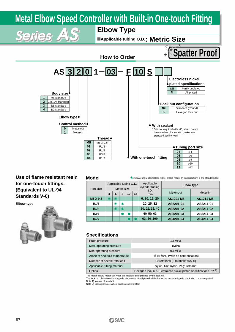
Elbow TypeApplicable tubing O.D.: Metric Size
Metal Elbow Speed Controller with Built-in One-touch Fitting
How to Order
Body sizeM5 standard
1/8, 1/4 standard3/8 standard1/2 standard
1234
With one-touch fitting
Tubing port size
Hexagon lock nut
Standard (Round)KNil
Lock nut configuration
With sealant
AS F
Applicable tubing O.D. Applicable cylinder tubing
I.D.mm
Metric size
6, 10, 16, 20
20, 25, 32
20, 25, 32, 40
40, 50, 63
63, 80, 100
4 6 8 10 12
Elbow type
10033 2 10 S
ø4ø6ø8
ø10ø12
0406081012
M501020304
Control method
Thread
Meter-outMeter-in
01
M5 X 0.8R1/8R1/4R3/8R1/2
Use of flame resistant resin for one-touch fittings.(Equivalent to UL-94 Standards V-0)
Model
SpecificationsProof pressure
Max. operating pressure
Min. operating pressure
Ambient and fluid temperature
Number of needle rotations
Applicable tubing material
Option
1.5MPa
1MPa
0.1MPa
–5 to 60°C (With no condensation)
10 rotations (8 rotations Note 1))
Nylon, Soft nylon, Polyurethane
Hexagon lock nut, Electroless nickel plated specifications Note 2)
indicates that electroless nickel plated model (N specification) is the standardized.
The meter-in and meter-out types are visually distinguished by the lock nut. The lock nut of the meter-out type is electroless nickel plated while that of the meter-in type is black zinc chromate plated.Note 1) In case of size M5.Note 2) Brass parts are all electroless nickel plated.
Elbow type
Meter-out Meter-in
AS1201-M5
AS2201-01
AS2201-02
AS3201-03
AS4201-04
Port size
M5 X 0.8
R1/8
R1/4
R3/8
R1/2
AS1211-M5
AS2211-01
AS2211-02
AS3211-03
AS4211-04
Elbow type
All platedPartly unplated
NNil
Electroless nickel plated specifications
∗ S is not required with M5, which do not have sealant. Types with gasket are standardized instead.
Spatter Proof
97

AS•F
Metal Body: Speed Controller with Built-in One-touch Fitting
Applicable tubing O.D.
mm
Connectionthread
4
8
10
12
6
M5 X 0.8
M5 X 0.8
R3/8
R1/8
R1/8
R1/2
R1/2
R1/4
R1/4
R3/8
Model
Meter-out
Elbow typeMeter-in
AS1201-M5-F04
AS1201-M5-F06
AS2201-01-F06S
-02-F06S
AS2201-01-F08S
-02-F08S
AS3201-03-F08S
AS3201-03-F10S
AS4201-04-F10S
AS4201-04-F12S
AS1211-M5-F04
AS1211-M5-F06
AS2211-01-F06S
-02-F06S
AS2211-01-F08S
-02-F08S
AS3211-03-F08S
AS3211-03-F10S
AS4211-04-F10S
AS4211-04-F12S
Elbow Type
JIS symbol
AS
Lubricant: Vaseline X12
Throttle Valve (Without Check Valve) X214 Clean Series 10-
Made to OrderOrderMade
(Example) AS1201-M5-F04-X12
(Example) AS1201-M5-F04-X214 Lubricant: Fluororesin grease, Double packaging
(Example) 10-AS1201-M5-F04
Oil Free (Sealant: PTFE Coated) + Without Check Valve (Throttle Valve)
(Example) AS1201-M5-F04-X21Note 1) Not a non particle generation type.Note 2) Only items with meter-out part numbers are available in case of throttle valves.
Note) Only items with meter-out part numbers are available in case of throttle valves.
X21
98

How to Order
Elbow Type/Universal TypeApplicable tubing O.D.: Metric Size
Speed Controller with Residual Pressure Exhaust Valve
Body size1/8, 1/4 standard
3/8 standard1/2 standard
234
TypeElbow
Universal23
Control method
With one-touch fitting
Meter-outMeter-in
01
ø4ø6ø8
ø10ø12
0406081012
Applicable tubing O.D.
Model
SpecificationsProof pressure
Max. operating pressure
Min. operating pressure
Ambient and fluid temperature
Number of needle rotations
Effective sectional area of residual pressure exhaust valve
Applicable tubing material
1.5MPa
1MPa
0.1MPa
–5 to 60°C (With no condensation)
10 rotations
0.8mm2
Nylon, Soft nylon, Polyurethane
Note 1) ∗Elbow type only.Note 2) Visual distinction between meter-out and meter-in types.
The meter-out and meter-in types can be visually distinguished by the lock nut. The lock nut of the meter-out type is electroless nickel plated while that of the meter-in type is black zinc chromate plated.
Metric size
AS 1F
Elbow type
Meter-out Meter-in Meter-out Meter-in
AS2201FE-01
AS2201FE-02
AS3201FE-03
AS4201FE-04
Universal typePort size
Applicable tubing O.D. Applicable cylinder tubing
I.D.mm
Metric size
∗R1/8
R1/4
R3/8
R1/2
20, 25, 32
20, 25, 32, 40
40, 50, 63
63, 80, 100
4 6 8 10 12
AS2301FE-01
AS2301FE-02
AS3301FE-03
AS4301FE-04
AS2211FE-01
AS2211FE-02
AS3211FE-03
AS4211FE-04
AS2311FE-01
AS2311FE-02
AS3311FE-03
AS4311FE-04
01 062 2 1
With residual pressure exhaust valve
E SK
Elbow type
Universal type
Residual pressure exhaust from cylinder.Residual pressure easily exhausted with one push.
Port sizeR1/8R1/4R3/8R1/2
01020304
With sealant
Hexagon lock nut
Residual Pressure Exhaust
99

AS•FE
Speed Controller with Residual Pressure Exhaust Valve
Applicable tubing O.D.
mm
Connectionthread
4
6
8
10
12
R1/8
R1/4
R1/8
R1/4
R3/8
R1/8
R1/4
R3/8
R1/8
R1/4
R3/8
R1/2
R3/8
R1/2
Model
Meter-out
Elbow typeMeter-in
AS2201FE-01-04SK
-02-04SK
AS2201FE-01-06SK
-02-06SK
AS3201FE-03-06SK
AS2201FE-01-08SK
-02-08SK
AS3201FE-03-08SK
AS2201FE-01-10SK
-02-10SK
AS3201FE-03-10SK
AS4201FE-04-10SK
AS3201FE-03-12SK
AS4201FE-04-12SK
Meter-out
Universal typeMeter-in
AS2301FE-01-04SK
-02-04SK
AS2301FE-01-06SK
-02-06SK
AS3301FE-03-06SK
AS2301FE-01-08SK
-02-08SK
AS3301FE-03-08SK
AS2301FE-02-10SK
AS3301FE-03-10SK
AS4301FE-04-10SK
AS3301FE-03-12SK
AS4301FE-04-12SK
AS2211FE-01-04SK
-02-04SK
AS2211FE-01-06SK
-02-06SK
AS3211FE-03-06SK
AS2211FE-01-08SK
-02-08SK
AS3211FE-03-08SK
AS2211FE-01-10SK
-02-10SK
AS3211FE-03-10SK
AS4211FE-04-10SK
AS3211FE-03-12SK
AS4211FE-04-12SK
AS2311FE-01-04SK
-02-04SK
AS2311FE-01-06SK
-02-06SK
AS3311FE-03-06SK
AS2311FE-01-08SK
-02-08SK
AS3311FE-03-08SK
AS2311FE-02-10SK
AS3311FE-03-10SK
AS4311FE-04-10SK
AS3311FE-03-12SK
AS4311FE-04-12SK
Elbow Type/Universal Type
JIS symbol
ASFE
Lubricant: Vaseline
(Example) AS2201FE-01-04SK-X12
X12
Throttle Valve (Without Check Valve)
(Example) AS2201FE-01-04SK-X214
X214
Made to OrderOrderMade
Oil Free (Sealant: PTFE Coated) + Without Check Valve (Throttle Valve)
(Example) AS2201FE-01-04SK-X21Note 1) Not a non particle generation type.Note 2) Only items with meter-out part numbers are available in case of throttle valves.
X21
Note) Only items with meter-out part numbers are available in case of throttle valves.
100

Lubricant: Vaseline
(Example) ASV120F-M3-04-X12
X12
Elbow Type/Tee Type
Elbow type
Tee type
ASV
Elbow Type/Tee TypeApplicable Tubing O.D.: Metric Size
Speed Exhaust Controller
How to Order
Body sizeM3 standardM5 standard1/8 standard1/4 standard3/8 standard
12345
With one-touch fitting
With spatter cover∗—
CNil
Spatter cover
∗ Only available to ASV310F, 410F and 510F.
Model SpecificationsSeries
Proof pressure
Max. operating pressure
Min. operating pressure
Ambient and fluid temperature
Number of needle rotations
Applicable tubing material
Option
1.5MPa
1MPa
0.1MPa
–5 to 60°C (With no condensation)
Nylon, Soft nylon, Polyurethane
Note 1) Pay attention to the maximum operating pressure when soft nylon, polyurethane is used. (Refer to Best Pneumatics vol. 4 for more information.)
Note 1)
0 F
ASV120F-M3
ASV220F-M5
ASV310F-01
ASV310F-02
ASV410F-01
ASV410F-02
ASV410F-03
ASV510F-02
ASV510F-03
ASV510F-04
Model
Applicable tubing O.D.Metric size
4 6 8 10 12
01 061ASV 3
Made to OrderOrderMade
0406081012
ø4ø6ø8
ø10ø12
M3M501020304
M3 X 0.5M5 X 0.8
R1/8R1/4R3/8R1/2
SealantSymbol
NilS
SealantWithout sealant
With sealant
Applicable modelASV120F, 220F
ASV310F, 410F, 510F
Applicable tubing O.D.
Note 1) Only M3 and M5 for the elbow type.
Port size
12
Union teeElbow Note1)
Model
M3 X 0.5
M5 X 0.8
R1/8
R1/4
R1/8
R1/4
R3/8
R1/4
R3/8
R1/2
Port size
ASV120F ASV220F ASV310F, 410F ASV510F
10 rotations 8 rotations 12 rotations 15 rotations
Hexagon lock nut With spatter cover, Hexagon lock nut
Integration of a quick exhaust valve and an exhaust restrictor.Permits high-speed cylinder operation.
Applicable tubing O.D.
mm
10
8
12
Model
Tee typeASV410F-02-08S
-03-08S
ASV410F-01-10S
-02-10S
-03-10S
ASV510F-02-10S
-03-10S
-04-10S
ASV510F-02-12S
-03-12S
-04-12S
Applicable tubing O.D.
mm
4
6
Model Connectionthread
Connectionthread Elbow type
Applicable tubing O.D.
mm
ModelConnectionthread Tee type
ASV120F-M3-04
ASV220F-M5-04
ASV220F-M5-06
M3 X 0.5
M5 X 0.8
M5 X 0.8
8
6ASV310F-01-06S
-02-06S
ASV310F-01-08S
-02-08S
ASV410F-01-08S
R1/8
R1/4
R1/8
R1/4
R1/8
R1/4
R3/8
R1/8
R1/4
R3/8
R1/4
R3/8
R1/2
R1/4
R3/8
R1/2
IN
EXH
OUT
JIS symbol
S
Hexagon type
Standard (Round)KNil
Lock nut configuration
Quick Exhaust
101

Connection thread b
ASP•F
Lubricant: Vaseline
(Example) ASP330F-01-06S-X12
X12
Universal Type
JIS symbol
ASP
Universal TypeApplicable Tubing O.D.: Metric Size
Speed Controller with Pilot Check Valve
How to Order
Model SpecificationsProof pressure
Max. operating pressure
Min. operating pressure
Pilot check valve operating pressure
Ambient and fluid temperature
Number of needle rotations
Applicable tubing material
1.5MPa
1MPa
0.1MPa
50% or more the operating pressure
–5 to 60°C (With no condensation)
10 rotations
Nylon, Soft nylon, PolyurethaneNote) Pay attention to the maximum operating pressure when soft nylon or polyurethane is used.
(Refer to Best Pneumatics vol. 4 for more information.)
ASP330F-01
ASP430F-02
ASP530F-03
ASP630F-04
Model
Applicable tubing O.D.
Metric size
6 8 10 12
Applicable tubing O.D.
mm
6
8
10
12
Model
Universal typeASP330F-01-06S
ASP430F-02-06S
ASP330F-01-08S
ASP430F-02-08S
ASP530F-03-08S
ASP530F-03-10S
ASP630F-04-10S
ASP630F-04-12S
Made to OrderOrderMade
Built-in pilot check valve to prevent drop down.Temporary intermediate stop. Emergency stop.
R1/8
R1/4
R3/8
R1/2
Port size
Note) Brass parts are all electroless nickel plated.
Pilot port
M5 X 0.8
Rc1/8
Rc1/8
Rc1/4
ASP 3
3456
1/8 Standard1/4 Standard3/8 Standard1/2 Standard
Body size
Type
Pilot check valve
3 UniversalPort size
With sealant
Symbol01020304
Cylinder sideR1/8R1/4R3/8R1/2
Applicable tubing O.D.Metric size
06081012
ø6ø8
ø10ø12
30F 01 06 S
With one-touch fitting
Pilot portM5 X 0.8
Rc1/8Rc1/8Rc1/4
Connectionthread a
R1/8
R1/4
R1/8
R1/4
R3/8
R3/8
R1/2
R1/2
Connectionthread b
M5 X 0.8
Rc1/8
M5 X 0.8
Rc1/8
Rc1/8
Rc1/8
Rc1/4
Rc1/4
Connection thread a Refer to Best Pneumatics vol. 3 for inch sizes.
Drop Prevention
102

How to Order
Elbow Type/Universal TypeApplicable Tubing O.D.: Metric Size
Tamper Proof Speed Controller
Model
SpecificationsProof pressure
Max. operating pressure
Min. operating pressure
Ambient and fluid temperature
Number of needle rotations
Applicable tubing material
1.5MPa
1MPa
0.1MPa
–5 to 60°C (With no condensation)
10 rotations (8 rotations )
Nylon, Soft nylon, Polyurethane
Note1) In case of AS1201F-M5 and AS1211F-M5 types.In case of AS1301F-M5 and AS1311F-M5 types.
Note2) Pay attention to the maximum operating pressure when soft nylon or polyurethane is used. (Refer to Best Pneumatics vol. 4 for more information.)
Note3) Brass parts of standard products are all electroless nickel plated.
Note 1) ∗Elbow type only.Note 2) The meter-in and meter-out types are visually distinguished by the flow direction symbol on the resin body.
Note1)
Elbow type
Meter-out Meter-in Meter-out Meter-in
AS1201F-M5
AS2201F-01
AS2201F-02
AS3201F-02
AS3201F-03
AS4201F-04
Universal typePort size
Applicable tubing O.D. Applicable cylinder
tubing I.D.mm
Metric size
∗
M5 X 0.8
R1/8
R1/4
R1/4
R3/8
R1/2
6,10,16,20
20,25,32
20,25,32,40
40,50,63
40,50,63
63,80,100
3.2 4 6 8 10 12
AS1301F-M5
AS2301F-01
AS2301F-02
AS3301F-02
AS3301F-03
AS4301F-04
AS1211F-M5
AS2211F-01
AS2211F-02
AS3211F-02
AS3211F-03
AS4211F-04
AS1311F-M5
AS2311F-01
AS2311F-02
AS3311F-02
AS3311F-03
AS4311F-04
Refer to Best Pneumatics vol. 3 for inch sizes.
Elbow type
Universal type
Special tool (AS-T-1)
Flow rate control with special tools for safety measures.
Body sizeM5 standard
1/8, 1/4 standard3/8 standard1/2 standard
1234
TypeElbow
Universal23
Control method
With one-touch fitting
Meter-outMeter-in
01
M5 X 0.8R1/8R1/4R3/8R1/2
01020304
M5Port size
ø3.2ø4ø6ø8
ø10ø12
Metric size
∗ Use ø1/8 tube.
0406081012
23
Applicable tubing O.D.
∗
Tamper proof typeNote)Flow control requires special tools,
which must be procured separately (Model number: AS-T-1).
AS 2 2 1 1 F — 01 — 06 S T
Note 2)
With sealantNote)S is not necessary in case of types with a
M5 port, which do not have sealant. Types with gasket are standardized.
103

AS•FT
Tamper Proof Speed Controllerwith One-touch Fitting
Applicable tubing O.D.
mm
Connectionthread
3.2
4
6
8
10
12
Model
Meter-out
Elbow typeMeter-in
AS1201F-M5-23T
AS2201F-01-23ST
AS1201F-M5-04T
AS2201F-01-04ST
-02-04ST
AS1201F-M5-06T
AS2201F-01-06ST
-02-06ST
AS3201F-02-06ST
-03-06ST
AS2201F-01-08ST
-02-08ST
AS3201F-02-08ST
-03-08ST
AS2201F-01-10ST
-02-10ST
AS3201F-02-10ST
-03-10ST
AS4201F-04-10ST
AS3201F-02-12ST
-03-12ST
AS4201F-04-12ST
AS1211F-M5-23T
AS2211F-01-23ST
AS1211F-M5-04T
AS2211F-01-04ST
-02-04ST
AS1211F-M5-06T
AS2211F-01-06ST
-02-06ST
AS3211F-02-06ST
-03-06ST
AS2211F-01-08ST
-02-08ST
AS3211F-02-08ST
-03-08ST
AS2211F-01-10ST
-02-10ST
AS3211F-02-10ST
-03-10ST
AS4211F-04-10ST
AS3211F-02-12ST
-03-12ST
AS4211F-04-12ST
Meter-out
Universal typeMeter-in
AS1301F-M5-23T
AS2301F-01-23ST
AS1301F-M5-04T
AS2301F-01-04ST
-02-04ST
AS1301F-M5-06T
AS2301F-01-06ST
-02-06ST
AS3301F-02-06ST
-03-06ST
AS2301F-01-08ST
-02-08ST
AS3301F-02-08ST
-03-08ST
AS2301F-02-10ST
AS3301F-02-10ST
-03-10ST
AS4301F-04-10ST
AS3301F-02-12ST
-03-12ST
AS4301F-04-12ST
AS1311F-M5-23T
AS2311F-01-23ST
AS1311F-M5-04T
AS2311F-01-04ST
-02-04ST
AS1311F-M5-06T
AS2311F-01-06ST
-02-06ST
AS3311F-02-06ST
-03-06ST
AS2311F-01-08ST
-02-08ST
AS3311F-02-08ST
-03-08ST
AS2311F-02-10ST
AS3311F-02-10ST
-03-10ST
AS4311F-04-10ST
AS3311F-02-12ST
-03-12ST
AS4311F-04-12ST
Elbow Type/Universal Type
JIS symbol
AS1F-T
Lubricant: Vaseline
(Example) AS1201F-M5-23T-X12
X12
Throttle Valve (Without Check Valve)
(Example) AS1201F-M5-23T-X214
X214 Clean Series
Lubricant: Fluororesin grease, Double packaging
(Example) 10-AS1201F-M5-23T
10-
Made to OrderOrderMade
M5 X 0.8
R1/8
M5 X 0.8
R1/8
R1/4
M5 X 0.8
R1/8
R1/4
R3/8
R1/8
R1/4
R3/8
R1/8
R1/4
R3/8
R1/2
R1/4
R3/8
R1/2
Oil Free (Sealant: PTFE Coated) + Without Check Valve (Throttle Valve)
(Example) AS1201F-M5-23T-X21Note 1) Not a non particle generation type.Note 2) Only items with meter-out part numbers are available in case of throttle valves.
X21
Note) Only items with meter-out part numbers are available in case of throttle valves.
104

lubricant: Vaseline
(Example) AS1001F-23T-X12
X12
(Example) AS1001F-23T-X214
X214 Clean Series
Lubricant: Fluororesin grease, Double packaging
(Example) 10-AS1001F-23T
10-
In-line Type
JIS symbol
AS1F-T
In-line TypeApplicable tubing O.D.: Metric Size
Tamper Proof Speed Controller
How to Order
Body sizeM5 standard1/8 standard1/4 standard3/8 standard1/2 standard
100200205300400
With one-touch fitting ø3.2ø4ø6
∗Use ø1/8 tube.
0406
23
Applicable tubing O.D.
ø8ø10ø12
081012
Model SpecificationsProof pressure
Max. operating pressure
Min. operating pressure
Ambient and fluid temperature
Number of needle rotations
Applicable tubing material
1.5MPa
1MPa
0.1MPa
–5 to 60°C (With no condensation)
10 rotations (8 rotations )
Nylon, Soft nylon, Polyurethane
Note 1) In case of type AS1001F.Note 2) Pay attention to the maximum operating pressure when soft nylon or polyurethane is used.
(Refer to Best Pneumatics vol. 4 for more information.)
Note 2)
Metric size
AS 1F
AS1001F
AS2001F
AS2051F
AS3001F
AS4001F
Model
Applicable tubing O.D. Applicable cylinder tubing
I.D.mm
Metric size
6, 10, 16, 20
20, 25, 32
20, 25, 32, 40
40, 50, 63
63, 80, 100
3.2 4 6 8 10 12
06200
Applicable tubing O.D.
mm
8
10
12
Model
In-line type
AS2051F-08T
AS3001F-08T
AS3001F-10T
AS4001F-10T
AS3001F-12T
AS4001F-12T
Applicable tubing O.D.
mm
3.2
4
6
Model
In-line type
AS1001F-23T
AS1001F-04T
AS2001F-04T
AS1001F-06T
AS2001F-06T
AS2051F-06T
AS3001F-06T
T
Made to OrderOrderMade
Tamper proof typeNote) Flow control requires special tools, which must
be procured separately (reference number: AS-T-1).
Flow control with special tools.For safety measures.
Special tool (AS-T-1)
Refer to Best Pneumatics vol. 4 for inch sizes.
∗
(Example) AS1001F-23T-X21Note 1) Not a non particle generation type.
X21
Throttle Valve (Without Check Valve)
Oil Free (Sealant: PTFE Coated) + Without Check Valve (Throttle Valve)
Note 1)
105

ASD•FT
lubricant: Vaseline
(Example) ASD230F-M5-04T-X12
X12 Clean Series
Lubricant: Fluororesin grease, Double packaging
(Example) 10-ASD230F-M5-04T
10-
Universal Type ASDF-T
Universal TypeApplicable tubing O.D.: Metric Size
Tamper Proof Dual Speed Controller
How to Order
Body size M5 standard1/8 standard1/4 standard3/8 standard1/2 standard
23456
With one-touch fitting
ø4ø6ø8
ø10ø12
0406081012
Applicable tubing O.D.
Model SpecificationsProof pressure
Max. operating pressure
Min. operating pressure
Ambient and fluid temperature
Number of needle rotations
Applicable tubing material
1.5MPa
1MPa
0.1MPa
–5 to 60°C (With no condensation)
10 rotations (8 rotations )
Nylon, Soft nylon, Polyurethane
Note 1) In case of ASD230F.Note 2) Pay attention to the maximum operating pressure when soft nylon or polyurethane is used.
(Refer to Best Pneumatics vol. 4 for more information.)Note 3) Brass parts of standard products are all electroless nickel plated.
Note 1)
Note 2)
Metric size
ASD S
ASD230F-M5
ASD330F-01
ASD430F-02
ASD530F-02
ASD530F-03
ASD630F-04
Model
Applicable tubing O.D.
Metric size
4 6 8 10 12
01 06 T
Applicable tubing O.D.
mm
10
12
Model
Universal typeASD430F-02-10ST
ASD530F-02-10ST
-03-10ST
ASD630F-04-10ST
ASD530F-02-12ST
-03-12ST
ASD630F-04-12ST
Applicable tubing O.D.
mm
4
6
8
ModelConnectionthread
ConnectionthreadUniversal type
ASD230F-M5-04T
ASD230F-M5-06T
ASD330F-01-06ST
ASD430F-02-06ST
ASD530F-02-06ST
-03-06ST
ASD330F-01-08ST
ASD430F-02-08ST
ASD530F-02-08ST
-03-08ST
3
Port size
F3 0
Made to OrderOrderMade
TypeUniversal3
M5 X 0.8R1/8R1/4R3/8R1/2
01020304
M5
Tamper proof typeNote)Flow control requires special tools, which must
be procured separately (Model number: AS-T-1).
JIS symbol
Lurch prevention.Speed control of single acting cylinder.Flow rate control with special tools for safety measures.
M5 X 0.8
R1/8
R1/4
R1/4
R3/8
R1/2
Port size
M5 X 0.8
M5 X 0.8
R1/8
R1/4
R3/8
R1/8
R1/4
R3/8
R1/4
R3/8
R1/2
R1/4
R3/8
R1/2
Refer to Best Pneumatics vol. 3 for inch sizes.
Lurch Prevention
With sealantNote)S is not necessary in case of types with a M5 port, which
do not have sealant. Types with gasket are standardized.
106

How to Order
Elbow Type/Universal TypeApplicable tubing O.D.: Metric Size
Flat Head Screw Driver Adjustable Speed Controller
Model
SpecificationsProof pressure
Max. operating pressure
Min. operating pressure
Ambient and fluid temperature
Number of needle rotations
Applicable tubing material
1.5MPa
1MPa
0.1MPa
–5 to 60°C (With no condensation)
10 rotations (8 rotations )
Nylon, Soft nylon, PolyurethaneNote 1) In case of types AS1201F-M5 and AS1211F-M5.
In case of types AS1301F-M5 and AS1311F-M5.Note 2) Pay attention to the maximum operating pressure when soft nylon or polyurethane is used.
(Refer to Best Pneumatics vol. 4 for more information.)Note 3) Brass parts of standard products are all electroless nickel plated.
Note 1) ∗Elbow type only.Note 2) The meter-out and meter-in types can be visually determined by the flow direction symbol on the resin body.
Note 1)
Elbow type
Meter-out Meter-in Meter-out Meter-in
AS1201F-M5
AS2201F-01
AS2201F-02
AS3201F-02
AS3201F-03
AS4201F-04
Universal typePort size
Applicable tubing O.D. Applicablecylinder
tubing I.D.mm
Metric size
∗M5 X 0.8
R1/8
R1/4
R1/4
R3/8
R1/2
6, 10, 16, 20
20, 25, 32
20, 25, 32, 40
40, 50, 63
40, 50, 63
63, 80, 100
3.2 4 6 8 10 12
AS1301F-M5
AS2301F-01
AS2301F-02
AS3301F-02
AS3301F-03
AS4301F-04
AS1211F-M5
AS2211F-01
AS2211F-02
AS3211F-02
AS3211F-03
AS4211F-04
AS1311F-M5
AS2311F-01
AS2311F-02
AS3311F-02
AS3311F-03
AS4311F-04
Refer to Best Pneumatics vol. 3 for inch sizes.
Elbow type
Universal type
Flow adjustment with flat head screw driver.For safety measures.
Body sizeM5 standard
1/8, 1/4 standard3/8 standard1/2 standard
1234
TypeElbow
Universal23
Control method
With one-touch fitting
Meter-outMeter-in
01
M5 X 0.8R1/8R1/4R3/8R1/2
01020304
M5Port size
ø3.2ø4ø6ø8
ø10ø12
Metric size
∗Use ø1/8 tubing .
0406081012
23
Applicable tubing O.D.
∗
Flat head screw driver adjustment type
AS 2 2 1 1 F – 01 – 06 S D
Note 2)
With sealantNote) S is not necessary in case of types with a M5 port, which
do not have sealant. Types with gasket are standardized.
107

Flat Head Screw Driver Adjustable Speed Controllerwith One-touch fitting
Applicable tubing O.D.
mm
Connectionthread
3.2
4
6
8
10
12
M5 X 0.8
R1/8
M5 X 0.8
R1/8
R1/4
M5 X 0.8
R1/8
R1/4
R3/8
R1/8
R1/4
R3/8
R1/8
R1/4
R3/8
R1/2
R1/4
R3/8
R1/2
Model
Meter-out
Elbow typeMeter-in
AS1201F-M5-23D
AS2201F-01-23SD
AS1201F-M5-04D
AS2201F-01-04SD
-02-04SD
AS1201F-M5-06D
AS2201F-01-06SD
-02-06SD
AS3201F-02-06SD
-03-06SD
AS2201F-01-08SD
-02-08SD
AS3201F-02-08SD
-03-08SD
AS2201F-01-10SD
-02-10SD
AS3201F-02-10SD
-03-10SD
AS4201F-04-10SD
AS3201F-02-12SD
-03-12SD
AS4201F-04-12SD
AS1211F-M5-23D
AS2211F-01-23SD
AS1211F-M5-04D
AS2211F-01-04SD
-02-04SD
AS1211F-M5-06D
AS2211F-01-06SD
-02-06SD
AS3211F-02-06SD
-03-06SD
AS2211F-01-08SD
-02-08SD
AS3211F-02-08SD
-03-08SD
AS2211F-01-10SD
-02-10SD
AS3211F-02-10SD
-03-10SD
AS4211F-04-10SD
AS3211F-02-12SD
-03-12SD
AS4211F-04-12SD
Meter-out
Universal typeMeter-in
AS1301F-M5-23D
AS2301F-01-23SD
AS1301F-M5-04D
AS2301F-01-04SD
-02-04SD
AS1301F-M5-06D
AS2301F-01-06SD
-02-06SD
AS3301F-02-06SD
-03-06SD
AS2301F-01-08SD
-02-08SD
AS3301F-02-08SD
-03-08SD
AS2301F-02-10SD
AS3301F-02-10SD
-03-10SD
AS4301F-04-10SD
AS3301F-02-12SD
-03-12SD
AS4301F-04-12SD
AS1311F-M5-23D
AS2311F-01-23SD
AS1311F-M5-04D
AS2311F-01-04SD
-02-04SD
AS1311F-M5-06D
AS2311F-01-06SD
-02-06SD
AS3311F-02-06SD
-03-06SD
AS2311F-01-08SD
-02-08SD
AS3311F-02-08SD
-03-08SD
AS2311F-02-10SD
AS3311F-02-10SD
-03-10SD
AS4311F-04-10SD
AS3311F-02-12SD
-03-12SD
AS4311F-04-12SD
Elbow Type/Universal Type
JIS symbol
AS1F-D
Lubricant: Vaseline
(Example) AS1201F-M5-23D-X12
X12
(Example) AS1201F-M5-23D-X214
X214 Clean Series
Lubricant: Fluororesin grease, Double packaging
(Example) 10-AS1201F-M5-23D
10-
Made to OrderOrderMade
Oil Free (Sealant: PTFE Coated) + Without Check Valve (Throttle Valve)
(Example) AS1201F-M5-23D-X21Note 1) Not a non particle generation type.Note 2) Only items with meter-out part numbers are available in case of throttle valves.
X21
AS•FD
Note) Only items with meter-out part numbers are available in case of throttle valves.
Throttle Valve (Without Check Valve)
108

lubricant: Vaseline
(Example) AS1001F-23D-X12
X12
(Example) AS1001F-23D-X214
X214 Clean Series
Lubricant: Fluororesin grease, Double package
(Example) 10-AS1001F-23D
10-
In-line Type AS1F-D
In-line TypeApplicable tubing O.D.: Metric Size
Flat Head Screw Driver Adjustable Speed Controller
How to Order
Body sizeM5 standard1/8 standard1/4 standard3/8 standard1/2 standard
100200205300400
With one-touch fitting
Applicable tubing O.D.
Model SpecificationsProof pressure
Max. operating pressure
Min. operating pressure
Ambient and fluid temperature
Number of needle rotations
Applicable tubing material
1.5MPa
1MPa
0.1MPa
–5 to 60°C (With no condensation)
10 rotations (8 rotations )
Nylon, Soft nylon, Polyurethane
Note 1) In case of type AS1001F.Note 2) Pay attention to the maximum operating pressure when soft nylon or polyurethane is used.
(Refer to Best Pneumatics vol. 4 for more information.)
Note 1)
Note 2)
Metric size
AS 1F
AS1001F
AS2001F
AS2051F
AS3001F
AS4001F
Model
Applicable tubing O.D. Applicable cylinder
tubing I.D.mm
Metric size
6, 10, 16, 20
20, 25, 32
20, 25, 32, 40
40, 50, 63
63, 80, 100
3.2 4 6 8 10 12
06200
Refer to Best Pneumatics vol. 3 for inch sizes.
Applicable tubing O.D.
mm
8
10
12
Model
In-line typeAS2051F-08D
AS3001F-08D
AS3001F-10D
AS4001F-10D
AS3001F-12D
AS4001F-12D
Applicable tubing O.D.
mm
3.2
4
6
Model
In-line typeAS1001F-23D
AS1001F-04D
AS2001F-04D
AS1001F-06D
AS2001F-06D
AS2051F-06D
AS3001F-06D
D
Made to OrderOrderMade
Flat head screw driver adjustment type
ø3.2 ∗
ø4ø6ø8
ø10ø12
230406081012
∗ Use ø1/8 tubing.
JIS symbol
Flow adjustment with flat head screw driver.For safety measures.
Oil Free (Sealant: PTFE Coated) + Without Check Valve (Throttle Valve)
(Example) AS1001F-23D-X21Note 1) Not a non particle generation type.
X21
Throttle Valve (Without Check Valve)
109

ASD•FD
Lubricant: Vaseline
(Example) ASD230F-M5-04D-X12
X12 Clean Series
Lubricant: Fluororesin grease, Double package
(Example) 10-ASD230F-M5-04D
10-
Universal Type
JIS symbol
ASDF-D
Universal TypeApplicable tubing O.D.: Metric Size
Flat Head Screw Driver Adjustable Dual Speed Controller
How to Order
Model SpecificationsProof pressure
Max. operating pressure
Min. operating pressure
Ambient and fluid temperature
Number of needle rotations
Applicable tubing material
1.5MPa
1MPa
0.1MPa
–5 to 60°C (With no condensation)
10 rotations (8 rotations )
Nylon, Soft nylon, Polyurethane
Note 1) In case of type ASD230F.Note 2) Pay attention to the maximum operating pressure when soft nylon or polyurethane is used.
(Refer to Best Pneumatics vol. 4 for more information.)Note 3) Brass parts of standard products are all electroless nickel plated.
Note 1)
Note 2)
ASD230F-M5
ASD330F-01
ASD430F-02
ASD530F-02
ASD530F-03
ASD630F-04
Model
Applicable tubing O.D.
Port size Metric size
M5 X 0.8
R1/8
R1/4
R1/4
R3/8
R1/2
4 6 8 10 12
Applicabletubing O.D.
mm
10
12
Model
Universal typeASD430F-02-10SD
ASD530F-02-10SD
-03-10SD
ASD630F-04-10SD
ASD530F-02-12SD
-03-12SD
ASD630F-04-12SD
Applicabletubing O.D.
mm
4
6
8
ModelConnectionthread
ConnectionthreadUniversal type
ASD230F-M5-04D
ASD230F-M5-06D
ASD330F-01-06SD
ASD430F-02-06SD
ASD530F-02-06SD
-03-06SD
ASD330F-01-08SD
ASD430F-02-08SD
ASD530F-02-08SD
-03-08SD
Made to OrderOrderMade
Body sizeM5 standard1/8 standard1/4 standard3/8 standard1/2 standard
23456
TypeUniversal3
With one-touch fitting
M5 X 0.8R1/8R1/4R3/8R1/2
01020304
M5Port size
ø4ø6ø8
ø10ø12
Metric size0406081012
Applicable tubing O.D.
Flat head screw driver adjustment type
ASD 3 3 0 F – 01 – 06 S D
Lurch prevention.Speed control of single acting cylinder.Flow adjustment with flat head screw driver.For safety measures.
R1/4
R3/8
R1/2
R1/4
R3/8
R1/2
M5 X 0.8
M5 X 0.8
R1/8
R1/4
R3/8
R1/8
R1/4
R3/8
Refer to Best Pneumatics vol. 3 for inch sizes.
Lurch Prevention
With sealantNote) S is not necessary in case of types with a M5 port, which
do not have sealant. Types with gasket are standardized.
110

Speed Controller with One-touch Fitting Related EquipmentRelated Equipment
Residual Pressure Exhaust Valve with One-touch Fitting Series KE
Holder Series TMH
Multiple Fitting Holder Series TMA
Without push button guardWith one-touch fitting
With push button guardWith one-touch fitting
With push button guardRc screw
Applicable tubing
In-line speed controllers and applicable holders
AS1001F
AS2001F
AS2051F
AS3001F
AS4001F
ø3.2
TMH-23JTMH-04J TMH-06J
TMH-06 TMH-08TMH-10 TMH-12
ø4 ø6 ø8 ø10 ø1223 04 06 08 10 12Body
size
Tubingsize
Applicable exhaust valve
Model
StationsModel
KEA06
KEB06
KEA08
KEB08
KEC-02
KEA-10
KEB-10
KEA-12
KEB-12
KEC-03
8
8
TMA-06
TMA-08
Applicable one-touch fittings
Union elbowUnion tee Straight union
KQ2L06-00KQL06-00
KQ2T06-00KQT06-00
KQ2H06-00KQH06-00
KQ2L08-00KQL08-00
KQ2T08-00KQT08-00
KQ2H08-00KQH08-00
6
6
TMA-10
TMA-12
KQ2L10-00KQL10-00
KQ2T10-00KQT10-00
KQ2H10-00KQH10-00
KQ2L12-00KQL12-00
KQ2T12-00KQT12-00
KQ2H12-00KQH12-00
KEA06
KEA08
KEA10
KEA12
6
8
10
12
ModelApplicable tubing O.D.
mm
KEB06
KEB08
KEB10
KEB12
6
8
10
12
ModelApplicable tubing O.D.
mm
KEC-02
KEC-03
Rc1/4
Rc3/8
ModelConnection
thread
Residual pressure inside the cylinder is released to the atmosphere by pressing the button.
Holder to secure an in-line type speed controller with one-touch fitting.
To secure series KE exhaust valves. To secure union tee KQT, union elbow KQL, straight union KQH.
JIS symbol
Residual Pressure Exhaust
111

Related Equipment
Male connector type: AKH
Check Valve with One-touch Fitting Series AKH/AKB
Quick Exhaust Valve with Built-in One-touch Fitting Series AQ40F
Straight type: AKH
With exhaust port fittingWith silencer
Thread size b
Thread size a
Applicable tubing O.D.
mmModel
AKH04-00
AKH06-00
AKH08-00
AKH10-00
AKH12-00
4
6
8
10
12
Applicable tubing O.D.
mmModel
AQ240F-04-00
AQ240F-06-00
AQ340F-06-00
4
6
6
Applicable tubing O.D.
mmModel
AQ240F-04-04
AQ240F-06-06
AQ340F-06-06
4
6
6
Applicable tubing O.D.
mm
4
6
8
10
12
Model
AKH04B-M5
-01S
AKH06B-M5
-01S
-02S
AKH08B-01S
-02S
-03S
AKH10B-02S
-03S
-04S
AKH12B-03S
-04S
AKH04A-M5
-01S
AKH06A-M5
-01S
-02S
AKH08A-01S
-02S
-03S
AKH10A-02S
-03S
-04S
AKH12A-03S
-04S
Connectionthread
M5 X 0.8
R1/8
M5 X 0.8
R1/8
R1/4
R1/8
R1/4
R3/8
R1/4
R3/8
R1/2
R3/8
R1/2
Thread size
Rc1/8
Rc1/4
Rc3/8
Rc1/2
R1/8
R1/4
R3/8
R1/2
Model
AKB01A-01S
AKB02A-02S
AKB03A-03S
AKB04A-04S
AKB01B-01S
AKB02B-02S
AKB03B-03S
AKB04B-04S
b
Bushing type: AKB
Space saving: Rectilinear IN-OUT tubing connections.
JIS symbol
Speed Controller with One-touch Fitting
With silencer
With exhaust port fitting
a
Related Equipment
Drop Prevention
Quick Exhaust
112

Air Saving ValvePFC Valve/QFC Valve
P.F.C valveQ.F.C valve
Working stroke
Return stroke
Air consumption reduced by 25%.The system with PFC and QFC valves cuts down consumption by 25% and drastically reduces running costs.
Reduces piping processes and saves space.The PFC valve drastically cuts down piping man hours and reduces installation space by integrating the regulator and the check valve while accommodating a built-in one-touch fitting.
Simplified 2 pressure control circuit.The pressure regulating function of the PFC valve provides the proper pressure in the proper place.
Improved cylinder response.Installation of a QFC valve in the secondary pressure circuit reduces lurching, delay in pressure transmission and delay in return.
Air consumption cut down by 25%It is not necessary to supply a high pressure to both sides of piston movement. The side with no work only requires a pressure sufficient to ensure smooth operation during the set time period (0.2MPa).The system with PFC and QFC valves cuts down consumption by 25% and drastically reduces running and equipment costs.
Working PrincipleExample of Circuit Using Conventional Models
Meter-in and meter-out operation prevents lurching to achieve smooth operation.
Large air consumption.
Meter-out control.
Air saving circuit.
Air saving circuit + Lurch prevention circuit.
The necessary pressure is supplied quickly after the piston reaches the stroke end.
Lurch in working stroke and delay in return.
The return stroke is controlled with a regulator.
Lurch prevention by meter-in control
Delay in pressure rise and delay in return at the stroke end.
Exhausts the primary pressure quickly to shorten delay time in return.
Operates at a low pressure necessary for return.
PFC valve/ASR
QFC valve/ASQ
Related Equipment
113

Series ASR/ASQPFC Valve: ASR
Applicable tubing O.D.
mm
6
8
10
12
Model
ASR430F-02-06S
ASR530F-02-06S
-03-06S
ASR430F-02-08S
ASR530F-02-08S
-03-08S
ASR430F-02-10S
ASR530F-02-10S
-03-10S
ASR630F-03-10S
-04-10S
ASR530F-02-12S
-03-12S
ASR630F-03-12S
-04-12S
Connectionthread
R1/4
R1/4
R3/8
R1/4
R1/4
R3/8
R1/4
R1/4
R3/8
R3/8
R1/2
R1/4
R3/8
R3/8
R1/2
Applicable tubing O.D.
mm
6
8
10
12
Model
ASR430F-02-06S-F20
ASR530F-02-06S-F20
-03-06S-F20
ASR430F-02-08S-F20
ASR530F-02-08S-F20
-03-08S-F20
ASR430F-02-10S-F20
ASR530F-02-10S-F20
-03-10S-F20
ASR630F-03-10S-F20
-04-10S-F20
ASR530F-02-12S-F20
-03-12S-F20
ASR630F-03-12S-F20
-04-12S-F20
Connectionthread
R1/4
R1/4
R3/8
R1/4
R1/4
R3/8
R1/4
R1/4
R3/8
R3/8
R1/2
R1/4
R3/8
R3/8
R1/2
Variable Set Pressure Type Fixed Set Pressure Type
PFC valveA regulator with check valve and a flow control valve are integrated in one body.
Speed Controller with One-touch Fitting Related Equipment
Related Equipment
114

Energy Saving ValvePFC Valve/QFC Valve Series ASR/ASQQFC Valve: ASQ
Applicable tubing O.D.
mm
6
8
10
12
Model
ASQ430F-02-06S
ASQ530F-02-06S
-03-06S
ASQ430F-02-08S
ASQ530F-02-08S
-03-08S
ASQ430F-02-10S
ASQ530F-02-10S
-03-10S
ASQ630F-03-10S
-04-10S
ASQ530F-02-12S
-03-12S
ASQ630F-03-12S
-04-12S
Connectionthread
R1/4
R1/4
R3/8
R1/4
R1/4
R3/8
R1/4
R1/4
R3/8
R3/8
R1/2
R1/4
R3/8
R3/8
R1/2
Applicable tubing O.D.
mm
6
8
10
12
Model
ASQ430F-02-06S-F20
ASQ530F-02-06S-F20
-03-06S-F20
ASQ430F-02-08S-F20
ASQ530F-02-08S-F20
-03-08S-F20
ASQ430F-02-10S-F20
ASQ530F-02-10S-F20
-03-10S-F20
ASQ630F-03-10S-F20
-04-10S-F20
ASQ530F-02-12S-F20
-03-12S-F20
ASQ630F-03-12S-F20
-04-12S-F20
Connectionthread
R1/4
R1/4
R3/8
R1/4
R1/4
R3/8
R1/4
R1/4
R3/8
R3/8
R1/2
R1/4
R3/8
R3/8
R1/2
Variable Set Pressure Type Fixed Set Pressure Type
QFC valveA pilot type switching valve and 2 direction flow control valve are integrated in one body.
Related Equipment
115

116

Tubing size: Metric SizePolyurethane Tubing
Series
Specifications
TU 04 25 BU 20
Model
O.D. mm
I.D. mm
Fluid
Max. operating pressure (at 20°C)
Burst pressure
Min. bending radius mm
Operating temperature
Material
Metric size
Tubing size
TU04254
2.5
TU060464
TU080585
TU1065106.5
TU1208128
Black (B)
White (W)
Red (R)
Blue (BU)
Yellow (Y)
Green (G)
Transparent (C)
Orange (YR)
–20m roll –100m roll
Length per rollSymbol Length
20100
20m roll100m roll
Color indicationSymbol Color
BWR
BUYGC
YR
BlackWhiteRedBlue
YellowGreen
TransparentOrage
Tubing I.D.
Tubing O.D.
Air, Water
0.8 MPa
Refer to burst pressure characteristics curve.
20
–20 to 60°C, Water: 0 to 40°C (With no condensation)
Polyurethane
10 15 27 35
How to Order
Burst Pressure Characteristics and Operating Pressure Curve
117

TU
Polyurethane Tubing
TU0425 Color symbol -20
TU0604 Color symbol -20
TU0805 Color symbol -20
TU1065 Color symbol -20
TU1208 Color symbol -20
O.D. I.D. O.D. I.D.Color (Color symbol) Model
Black (B)White (W)Red (R)Blue (BU)Yellow (Y)Green (G)Transparent (C)Orange (YR)Black (B)White (W)Red (R)Blue (BU)Yellow (Y)Green (G)Transparent (C)Orange (YR)Black (B)White (W)Red (R)Blue (BU)Yellow (Y)Green (G)Transparent (C)Orange (YR)Black (B)White (W)Red (R)Blue (BU)Yellow (Y)Green (G)Transparent (C)Orange (YR)Black (B)White (W)Red (R)Blue (BU)Yellow (Y)Green (G)Transparent (C)Orange (YR)
4
6
8
10
12
2.5
4
5
6.5
8
Made to OrderOrderMadeOrderMade
4681012
2.545
6.58
TU0425 Color symbol -100-X3TU0604 Color symbol -100-X3TU0805 Color symbol -100-X3TU1065 Color symbol -100-X3TU1208 Color symbol -100-X3
O.D. I.D. Model
Color indication —B (Black), W (White), R (Red), BU (Blue), Y (Yellow), G (Green), C (Transparent), YR (Orange)
TU0425 Color symbol -100
TU0604 Color symbol -100
TU0805 Color symbol -100
TU1065 Color symbol -100
TU1208 Color symbol -100
Color (Color symbol) Model
Black (B)White (W)Red (R)Blue (BU)Yellow (Y)Green (G)Transparent (C)Orange (YR)Black (B)White (W)Red (R)Blue (BU)Yellow (Y)Green (G)Transparent (C)Orange (YR)Black (B)White (W)Red (R)Blue (BU)Yellow (Y)Green (G)Transparent (C)Orange (YR)Black (B)White (W)Red (R)Blue (BU)Yellow (Y)Green (G)Transparent (C)Orange (YR)Black (B)White (W)Red (R)Blue (BU)Yellow (Y)Green (G)Transparent (C)Orange (YR)
4
6
8
10
12
2.5
4
5
6.5
8
Reel X3 Clean Series
Only available in 20m rolls.
(Example) 10-TU0425W-20
100m roll
10-
20m Roll 100m Roll
118

Tubing size: Metric SizeSoft Polyurethane Tubing
Series
Specifications
Burst Pressure Characteristics and Operating Pressure Curve
TUS 10 65 B 100
Model
O.D. mm
I.D. mm
Fluid
Max. operating pressure (20°C)
Burst pressure
Applicable fitting
Min. bending radius mm
Operating temperature
Material
Metric size
Tubing
TUS04254
2.5
TUS060464
TUS080585
TUS1065106.5
TUS1208128
Black (B)
White (W)
Red (R)
Blue (BU)
Yellow (Y)
Green (G)
Translucent (N)
Yellow brown (YB)
–20m roll –100m reel
Length per rollSymbol Length
20100
20m roll100m reel (Black and Blue only)
Color indicationSymbol Color
BWR
BUYGN
YB
BlackWhiteRedBlue
YellowGreen
TranslucentYellow brown
Tubing I.D.
Tubing O.D.
Supersoft
TUS Related AccessoriesInner SleeveSeries TJReinforces soft polyurethane tubing connected to one-touch fitting.Insert an inner sleeve into soft polyurethane tubing.
Model Length1819
20.52324
TJ-0425TJ-0604TJ-0805TJ-1065TJ-1208
Applicable tubing modelTUS0425TUS0604TUS0805TUS1065TUS1208
Model
Tubing drawing strength N(with one-touch fitting)
Without inner sleeve
With inner sleeve
Air
0.6MPa
Refer to burst pressure characteristics curve.
One-touch fitting, insert fittings, hose nipple
–20 to 60°C (With no freezing)
Polyurethane
8 15 15 22 29
15 60 60 85 110
80 230 250 300 480
Note 1) Not transparent but translucent owing to the material.
How to Order
Note 1)
119

TUS
Soft Polyurethane Tubing
TUS0425 Color symbol -20
TUS0604 Color symbol -20
TUS0805 Color symbol -20
TUS1065 Color symbol -20
TUS1208 Color symbol -20
O.D. I.D. O.D. I.D.Color Model
Black (B)White (W)Red (R)Blue (BU)Yellow (Y)Green (G)Translucent (N)Yellow brown (YB)Black (B)White (W)Red (R)Blue (BU)Yellow (Y)Green (G)Translucent (N)Yellow brown (YB)Black (B)White (W)Red (R)Blue (BU)Yellow (Y)Green (G)Translucent (N)Yellow brown (YB)Black (B)White (W)Red (R)Blue (BU)Yellow (Y)Green (G)Translucent (N)Yellow brown (YB)Black (B)White (W)Red (R)Blue (BU)Yellow (Y)Green (G)Translucent (N)Yellow brown (YB)
4
6
8
10
12
2.5
4
5
6.5
8
TUS0425 Color symbol -100
TUS0604 Color symbol -100
TUS0805 Color symbol -100
TUS1065 Color symbol -100
TUS1208 Color symbol -100
Color Model
Black (B)Blue (BU)Black (B)Blue (BU)Black (B)Blue (BU)Black (B)Blue (BU)Black (B)Blue (BU)
4
6
8
10
12
2.5
4
5
6.5
8
Note 1) Not transparent but translucent owing to the material.
20m Roll 100m on Reel
Note 1)
Note 1)
Note 1)
Note 1)
Note 1)
120

Tubing size: Metric SizeNylon Tubing
SeriesBurst Pressure Characteristics and Operating Pressure Curve
Specifications
20T 04 25 B
Length per roll
Color indicationSymbol Color
Tubing I.D.
B BlackW WhiteR Red
BU BlueY YellowG Green
Symbol Length20 20m roll100 100m roll (Black and White only)
Model
Fluid
Max. operating pressure (20°C)
Burst pressure
Min. bending radius mm
Operating temperature
Material
Air, Water
1.5MPa
Refer to burst pressure characteristics curve.
75604836242513–20 to 60°C, Water: 0 to 40°C (With no condensation)
Nylon 12
Metric size
Tubing
T04254
2.5
T040343
T060464
T06456
4.5
T080686
T1075107.5
T1209129
T16131613
O.D. mm
I.D. mm
White (W)
Red (R)
Blue (BU)
Yellow (Y)
Green (G)
Black (B)
100
–20m roll –100m roll (T1613 is on reel.)
Tubing O.D.
How to Order
121

T
Nylon Tubing
20m Roll
2.5
3
4
4.5
6
7.5
9
13
4
6
8
10
12
16
T0425 Color symbol -20
T0403 Color symbol -20
T0604 Color symbol -20
T0645 Color symbol -20
T0806 Color symbol -20
T1075 Color symbol -20
T1209 Color symbol -20
T1613 Color symbol -20
Black (B)White (W)Red (R)Blue (BU)Yellow (Y)Green (G)Black (B)White (W)Black (B)White (W)Red (R)Blue (BU)Yellow (Y)Green (G)Black (B)White (W)Black (B)White (W)Red (R)Blue (BU)Yellow (Y)Green (G)Black (B)White (W)Red (R)Blue (BU)Yellow (Y)Green (G)Black (B)White (W)Red (R)Blue (BU)Yellow (Y)Green (G)Black (B)White (W)
O.D. I.D. O.D. I.D.Color(Color symbol)
Model
100m Roll
4
6
8
10
12
16
2.5
4
4.5
6
7.5
9
13
T0425 Color symbol -100
T0604 Color symbol -100
T0645 Color symbol -100
T0806 Color symbol -100
T1075 Color symbol -100
T1209 Color symbol -100
T1613 Color symbol -100∗
Black (B)White (W)Black (B)White (W)Black (B)Black (B)White (W)Black (B)White (W)Black (B)White (W)Black (B)White (W)
Color(Color symbol)
Model
T1613 is on reel.
Made to OrderOrderMadeOrderMade
4
6
81012
2.534
4.56
7.59
T0425 Color symbol -100-X3T0403 Color symbol -100-X3T0604 Color symbol -100-X3T0645 Color symbol -100-X3T0806 Color symbol -100-X3T1075 Color symbol -100-X3T1209 Color symbol -100-X3
O.D. I.D. Model
Color symbol -B (Black), W (White), R (Red), BU (Blue), Y (Yellow), G (Green)
Reel X3100m roll
122

Tubing size: Metric SizeSoft Nylon Tubing
Series
Specifications
TS 06 04 W 100
Model
O.D. mm
I.D. mm
Fluid
Max. operating pressure (20°C)
Burst pressure
Min. bending radius mm
Operating temperature
Material
Metric size
Tubing
TS04254
2.5
TS060464
TS080686
TS1075107.5
TS1209129
TS16121612
Black (B)
White (W)
Red (R)
Blue (BU)
Yellow (Y)
Green (G)
–20m roll –100m roll (TS1612 is on reel.)
Length per rollSymbol Length
20100
20m roll100m roll (Black and White only)
Color indicationSymbol Color
BWR
BUYG
BlackWhiteRedBlue
YellowGreen
Tubing I.D.
TubingO.D.
Pliable
Air
1.0MPa
Refer to burst pressure characteristics curve.
–20 to 60°C (With no condensation)
Nylon 11, Nylon 12
12 15 23 27 31 60
How to Order
Burst Pressure Characteristics and Operating Pressure Curve
123

TS
Soft Nylon Tubing
20m Roll
TS0425 Color symbol -20
TS0604 Color symbol -20
TS0806 Color symbol -20
TS1075 Color symbol -20
TS1209 Color symbol -20
TS1612 Color symbol -20
O.D. I.D. Color (Color symbol) Model
100m Roll
Black (B)White (W)Red (R)Blue (BU)Yellow (Y)Green (G)Black (B)White (W)Red (R)Blue (BU)Yellow (Y)Green (G)Black (B)White (W)Red (R)Blue (BU)Yellow (Y)Green (G)Black (B)White (W)Red (R)Blue (BU)Yellow (Y)Green (G)Black (B)White (W)Red (R)Blue (BU)Yellow (Y)Green (G)Black (B)White (W)
4
6
8
10
12
16
2.5
4
6
7.5
9
12
TS0425 Color symbol -100
TS0604 Color symbol -100
TS0806 Color symbol -100
TS1075 Color symbol -100
TS1209 Color symbol -100
TS1612 Color symbol -100
Color (Color symbol) Model
Black (B)White (W)Black (B)White (W)Black (B)White (W)Black (B)White (W)Black (B)White (W)Black (B)White (W)
4
6
8
10
12
16
2.5
4
6
7.5
9
12
TS1612 is on reel.
Made to OrderOrderMadeOrderMade
4681012
2.546
7.59
TS0425 Color symbol -100-X3TS0604 Color symbol -100-X3TS0806 Color symbol -100-X3TS1075 Color symbol -100-X3TS1209 Color symbol -100-X3
Model
Reel X3
Color symbol -B (Black), W (White), R (Red), BU (Blue), Y (Yellow), G (Green)
100m roll
O.D. I.D.
O.D. I.D.
124

Tubing size: Metric SizeHard Polyurethane Tubing
TUH 06 04 B 20Length per roll
Symbol Length20
10020m roll
100m roll
Color indicationSymbol Color
BlackOpalBlue
Translucent
Tubing I.D.
Tubing O.D.
Note 1) Consult SMC regarding other fluids. Water cannot be used because of occurrence of hydrolysis.
Note 2) The maximum operating pressure is the value at 20°C. Refer to the burst pressure characteristics and operating pressure curve for other temperatures. Abnormal temperature rises due to adiabatic compression can cause tubing to burst.
Note 3) The minimum bending radius is measured at 20°C based on the method shown in the figure at the left. At higher temperatures, breakage or flattening may occur even with a value larger than the minimum bending radius.
How to Order
Series
Specifications
Model
O.D. mm
I.D. mm
Model
O.D. mm
I.D. mm
Standard
High pressure
Fluid
Burst pressure
Operating temperature
Material
Metric size
Tubing
TUH04284
2.8TUH0425
42.5
TUH060464
TUH080585
TUH1065106.5
TUH1208128
TUH06446
4.4
TUH08588
5.8
TUH1073107.3
TUH1288128.8
Black (B)
Opal (W)
Blue (BU)
Translucent (N)
–20m roll –100m
Air Note 1)
0.8MPa Note 2)
1.0MPa Note 2)
Refer to burst pressure characteristics curve.
–20 to 60°C
Polyurethane
10 18 24 30 36
10 15 20 27 35
Max. operating pressure (20°C)
Min. bending radius mm
Standard type
High pressure type
Standard type
High pressure type
Operating pressure 1.0MPa (at 20°C)TUH / High pressure type(Has the same operating pressure as series TS soft nylon tubing, and a bending strength equivalent to that of series TU polyurethane tubing.)
Effective sectional area increased by approx. 44% at the maximum.TUH / Standard type(Compared with polyurethane tubing TU0805: O.D. 8 mm , length 1 m)
Standard type
High pressure type
Burst Pressure Characteristics and Operating Pressure Curve
5
4
3
2
1
0-20 0 20
Operating temperature °C
Bur
st p
ress
ure
MP
a
40 60
maximum operating preMax. operating pressure
5
6
7
4
3
2
1
0-20 0 20
Operating temperature °C
Bur
st p
ress
ure
MP
a
40 60
maximum operating preMax. operating pressure
Standard type
High pressure type
BWBUN
125

TUH
Hard Polyurethane Tubing
20m Roll
TUH0428 Color symbol -20
TUH0644 Color symbol -20
TUH0858 Color symbol -20
TUH1073 Color symbol -20
TUH1288 Color symbol -20
O.D. I.D. Color (Color symbol) Model
100m Roll
Black (B)Opal (W)Blue (BU)Translucent (N)Black (B)Opal (W)Blue (BU)Translucent (N)Black (B)Opal (W)Blue (BU)Translucent (N)Black (B)Opal (W)Blue (BU)Translucent (N)Black (B)Opal (W)Blue (BU)Translucent (N)
4
6
8
10
12
2.8
4.4
5.8
7.3
8.8
TUH0428 Color symbol -100
TUH0644 Color symbol -100
TUH0858 Color symbol -100
TUH1073 Color symbol -100
TUH1288 Color symbol -100
Color (Color symbol) Model
Black (B)Opal (W)Blue (BU)Translucent (N)Black (B)Opal (W)Blue (BU)Translucent (N)Black (B)Opal (W)Blue (BU)Translucent (N)Black (B)Opal (W)Blue (BU)Translucent (N)Black (B)Opal (W)Blue (BU)Translucent (N)
4
6
8
10
12
2.8
4.4
5.8
7.3
8.8
TUH0425 Color symbol -20
TUH0604 Color symbol -20
TUH0805 Color symbol -20
TUH1065 Color symbol -20
TUH1208 Color symbol -20
O.D. I.D. Color (Color symbol) Model
Black (B)Opal (W)Blue (BU)Translucent (N)Black (B)Opal (W)Blue (BU)Translucent (N)Black (B)Opal (W)Blue (BU)Translucent (N)Black (B)Opal (W)Blue (BU)Translucent (N)Black (B)Opal (W)Blue (BU)Translucent (N)
4
6
8
10
12
2.5
4
5
6.5
8
TUH0425 Color symbol -100
TUH0604 Color symbol -100
TUH0805 Color symbol -100
TUH1065 Color symbol -100
TUH1208 Color symbol -100
Color (Color symbol) Model
Black (B)Opal (W)Blue (BU)Translucent (N)Black (B)Opal (W)Blue (BU)Translucent (N)Black (B)Opal (W)Blue (BU)Translucent (N)Black (B)Opal (W)Blue (BU)Translucent (N)Black (B)Opal (W)Blue (BU)Translucent (N)
4
6
8
10
12
2.5
4
5
6.5
8
High Pressure Type
Standard Type
O.D. I.D.
O.D. I.D.
126

Tubing size: Metric SizePolyurethane Coil Tubing
Specifications
Coil Tubing
Model
O.D.
4
6
8
I.D.
1
2
3
1
2
3
1
1.5
1
2
1.5
1
2
Max. operating length mNumber of rolls Model
2.5
4
5
Color
Black (B)Black (B)Black (B)Black (B)Black (B)Black (B)Black (B)
TCU0425B-1
1
TCU0425B-2
2
4
2.5
TCU0425B-3
3
TCU0604B-1
1
Air Note 1)
0.8MPa
Refer to burst pressure characteristics curve.
–20 to 60°C
Polyurethane
Black
TCU0604B-2
2
6
4
TCU0604B-3
3
TCU0805B-1
1
8
5
Note 1) Consult SMC regarding other fluids.Note 2) Refer to the burst pressure characteristics and operating pressure curve for other temperatures.
Avoid abnormal temperature rises due to adiabatic compression.
Number of rolls
Tubing O.D. mm
Tubing I.D. mm
Fluid
Max. operating pressure (20°C)
Burst pressure
Operating temperature
Material
Color
For compact piping.
TCU0425B-1TCU0425B-2TCU0425B-3TCU0604B-1TCU0604B-2TCU0604B-3TCU0805B-1
4
6
8
10
12
2.5
4
5
6.5
8
123123121212
3 to 903 to 903 to 633 to 903 to 663 to 443 to 903 to 403 to 453 to 353 to 353 to 30
Length per roll Coil windingst
Made to OrderOrderMadeOrderMade
TCU0425 Color symbol -1- Coil windings -X6TCU0425 Color symbol -2- Coil windings -X6TCU0425 Color symbol -3- Coil windings -X6TCU0604 Color symbol -1- Coil windings -X6TCU0604 Color symbol -2- Coil windings -X6TCU0604 Color symbol -3- Coil windings -X6TCU0805 Color symbol -1- Coil windings -X6TCU0805 Color symbol -2- Coil windings -X6TCU1065 Color symbol -1- Coil windings -X6TCU1065 Color symbol -2- Coil windings -X6TCU1208 Color symbol -1- Coil windings -X6TCU1208 Color symbol -2- Coil windings -X6
O.D. I.D. Model
Color symbol —B (Black), W (White), R (Red), BU (Blue), Y (Yellow), G (Green), C (Transparent), YR (Orange)
Change in the Number of Coil Windings and Color X6 Clean Series
(Example) 10-TCU0425B-1
10-
Burst Pressure Characteristics and Operating Pressure Curve
Note 2)
127

TFU
2 to 82 to 82 to 62 to 32 to 3
4681012
2.545
6.58
TFU0425 Color symbol - Length per roll -10-X4
TFU0604 Color symbol - Length per roll -10-X4
TFU0805 Color symbol - Length per roll -10-X4
TFU1065 Color symbol - Length per roll -10-X4
TFU1208 Color symbol - Length per roll -10-X4
O.D. I.D. Number model
Tubing size: Metric SizePolyurethane Flat Tubing
Specifications
TFU 04 25 B 2Number of tubes
Symbol Number of tubes23
23
Color indicationSymbol Color
B BlackTubing I.D.
Tubing O.D.
For compact piping.
Model
2 3 2 3 2
TFU0425B-2
TFU0425B-3
TFU0604B-2
TFU0604B-3
TFU0805B-2
TFU0805B-3
3
4
2.5
10
6
4 Air Note 1)
0.8 MPa
Refer to burst pressure characteristics curve.
–20 to 60°C (With no condensation)
Polyurethane
Black
15
10
8
5
20
Length per roll
Tubing O.D. mm
Tubing I.D. mm
Fluid
Max. operating pressure (20°C)
Burst pressure
Operating temperature
Material
Color
Min. bending radius mm
Tubing length per roll (m)Note 1) Consult SMC regarding other fluids.Note 2) Refer to the burst pressure characteristics and operating pressure curve on page 117 for other
temperatures. Avoid abnormal temperature rises due to adiabatic compression.
TFU0425B-2TFU0425B-3TFU0604B-2TFU0604B-3TFU0805B-2TFU0805B-3
O.D. I.D. Number of rollsColor (Color symbol) Model
Black (B)
Black (B)
Black (B)
Black (B)
Black (B)
Black (B)
4
6
8
2.5
4
5
232323
Made to OrderOrderMadeOrderMade
Change in the Number of Rolls and Color X4
Clean Series
(Example) 10-TFU0425B-2
10-
How to Order
10m Roll
Note 2)
Color symbol —W (White), R (Red), BU (Blue), Y (Yellow), G (Green), C (Transparent), YR (Orange)
10m roll
232323
4
6
8
2.5
4
5
TFU0425 Color symbol -2-50-X3TFU0425 Color symbol -3-50-X3TFU0604 Color symbol -2-50-X3TFU0604 Color symbol -3-50-X3TFU0805 Color symbol -2-50-X3TFU0805 Color symbol -3-50-X3
Model
Reel X3
Color symbol —B (Black), W (White), R (Red), BU (Blue), Y (Yellow), G (Green), C (Transparent), YR (Orange)
50m roll
23232
4
6
8
2.5
4
5
TFU0425 Color symbol -2-100-X3TFU0425 Color symbol -3-100-X3TFU0604 Color symbol -2-100-X3TFU0604 Color symbol -3-100-X3TFU0805 Color symbol -2-100-X3
Number Model
Color symbol —B (Black), W (White), R (Red), BU (Blue), Y (Yellow), G (Green), C (Transparent), YR (Orange)
100m roll
NumberO.D. I.D. O.D. I.D.
128

Tubing size: Metric SizeClean Tubing: Polyolefin Tubing
Specifications
TPH 06 04 B 20
Fluid
Max. operating pressure (20°C)
Min. bending radius mm
Burst pressure
Operating temperature
Material
Length per rollSymbol Length
20100
20m roll100m roll
Color indicationSymbol Color
WBR
BUYG
WhiteBlackRedBlue
YellowGreen
Tubing I.D.
Tubing O.D.
Air, Nitrogen gas, Water (Pure water) Note 1)
35
Refer to burst pressure characteristics curve.
–20 to 80°C, Water: 5 to 80°C
Polyolefine resin
Series
Model
O.D. mm
I.D. mm
Metric size
Tubing
TPH04254
2.5
TPH060464
TPH080686
TPH1075107.5
TPH1209129
White (W)
Black (B)
Red (R)
Blue (BU)
Yellow (Y)
Green (G)
–20m roll –100m roll
15 25 45 55
1.0MPa 0.7MPa
Note 1) Contact SMC regarding other fluids.Note 2) The maximum operating pressure is the value at 20°C.
Refer to the burst pressure characteristics and operating pressure curve for other temperatures. Abnormal temperature rises due to adiabatic compression can cause tubing to burst.
Note 3) The minimum bending radius is measured at 20°C based on the method shown in the figure at the left. At higher temperatures, breakage or flattening may occur even with a value larger than the minimum bending radius.
How to Order
Note 2)
Burst Pressure Characteristics and Operating Pressure Curve
Operating temperature °C
Max. operating pressure (TPH0425,TPH0604)
TPH0806,TPH1075,TPH1209
Burst pressureTPH0425,TPH0604
Burst pressure
Max. operating pressure(TPH0806,TPH1075,TPH1209)
Bur
st p
ress
ure
MP
a
–20 00
1
2
3
4
5
20 40 60 80
Series TP has less resistance to lithium grease and is not suitable for piping of pneumatic equipment using lithium grease.
Caution
Clean
129

TPH
Clean Tubing: Polyolefin Tube
20m Roll
TPH0425 Color symbol -20
TPH0604 Color symbol -20
TPH0806 Color symbol -20
TPH1075 Color symbol -20
TPH1209 Color symbol -20
O.D. I.D. Color (Color symbol) Model
White (W)Black (B)Red (R)Blue (BU)Yellow (Y)Green (G)White (W)Black (B)Red (R)Blue (BU)Yellow (Y)Green (G)White (W)Black (B)Red (R)Blue (BU)Yellow (Y)Green (G)White (W)Black (B)Red (R)Blue (BU)Yellow (Y)Green (G)White (W)Black (B)Red (R)Blue (BU)Yellow (Y)Green (G)
4
6
8
10
12
2.5
4
6
7.5
9
TPH0425 Color symbol -100
TPH0604 Color symbol -100
TPH0806 Color symbol -100
TPH1075 Color symbol -100
TPH1209 Color symbol -100
Color (Color symbol) Model
White (W)Black (B)Red (R)Blue (BU)Yellow (Y)Green (G)White (W)Black (B)Red (R)Blue (BU)Yellow (Y)Green (G)White (W)Black (B)Red (R)Blue (BU)Yellow (Y)Green (G)White (W)Black (B)Red (R)Blue (BU)Yellow (Y)Green (G)White (W)Black (B)Red (R)Blue (BU)Yellow (Y)Green (G)
4
6
8
10
12
2.5
4
6
7.5
9
100m Roll
O.D. I.D.
130

Tubing size: Metric SizeClean Tubing: Soft Polyolefine Tubing
Specifications
TPS 06 04 B 20
Fluid
Max. operating pressure (20°C)
Min. bending radius mm
Burst pressure
Operating temperature
Material
Length per rollSymbol Length
20100
20m roll100m roll
Color indicationSymbol Color
WBR
BUYG
WhiteBlackRedBlue
YellowGreen
Tubing I.D.
Tubing O.D.
Air, Nitrogen gas (Pure water) Note 1)
0.7MPa
25
Refer to burst pressure characteristics curve.
–20 to 80°C, Water: 5 to 80°C
Polyolefine resin
Series
Model
O.D. mm
I.D. mm
Metric size
Tubing
TPS04254
2.5
TPS060464
TPS080585
TPS1065106.5
TPS1208128
White (W)
Black (B)
Red (R)
Blue (BU)
Yellow (Y)
Green (G)
–20m roll –100m roll
10 20 30 40
Note 1) Contact SMC regarding other fluids.Note 2) The maximum operating pressure is the value at 20°C.
Refer to the burst pressure characteristics and operating pressure curve for other temperatures. Abnormal temperature rises due to adiabatic compression can cause tubing to burst.
Note 3) The minimum bending radius is measured at temperature of 20°C and O.D. variable rate 10% or less. At higher temperatures, breakage or flattening may occur even with a value larger than the minimum bending radius.
How to Order
Burst Pressure Characteristics and Operating Pressure Curve
Operating temperature °C
Max. operating pressureBur
st p
ress
ure
MP
a
–20 00
1
2
3
4
5
20 40 60 80
Burst pressure
Note 2)
Series TP has less resistance to lithium grease and is not suitable for piping of pneumatic equipment using lithium grease.
Caution
Clean
131

TPS
Clean Tubing: Soft Polyolefine Tubing
20m Roll
TPS0425 Color symbol -20
TPS0604 Color symbol -20
TPS0805 Color symbol -20
TPS1065 Color symbol -20
TPS1208 Color symbol -20
O.D. I.D. Color (Color symbol) Model
100m Roll
White (W)Black (B)Red (R)Blue (BU)Yellow (Y)Green (G)White (W)Black (B)Red (R)Blue (BU)Yellow (Y)Green (G)White (W)Black (B)Red (R)Blue (BU)Yellow (Y)Green (G)White (W)Black (B)Red (R)Blue (BU)Yellow (Y)Green (G)White (W)Black (B)Red (R)Blue (BU)Yellow (Y)Green (G)
4
6
8
10
12
2.5
4
5
6.5
8
TPS0425 Color symbol -100
TPS0604 Color symbol -100
TPS0805 Color symbol -100
TPS1065 Color symbol -100
TPS1208 Color symbol -100
Color (Color symbol) Model
White (W)Black (B)Red (R)Blue (BU)Yellow (Y)Green (G)White (W)Black (B)Red (R)Blue (BU)Yellow (Y)Green (G)White (W)Black (B)Red (R)Blue (BU)Yellow (Y)Green (G)White (W)Black (B)Red (R)Blue (BU)Yellow (Y)Green (G)White (W)Black (B)Red (R)Blue (BU)Yellow (Y)Green (G)
4
6
8
10
12
2.5
4
5
6.5
8
O.D. I.D.
132

Tubing sizing: Metric SizeAntistatic Polyurethane Tubing
Series
Specifications
Burst Pressure Characteristics and Operating Pressure Curve
TAU 10 65 B 100
Model
O.D. mm
I.D. mm
Burst pressure
Min. bending radius mm
Operating temperature
Material
Surface resistance
Metric size
Tubing
TAU32203.22
TAU04254
2.5
TAU060464
TAU080585
TAU1065106.5
TAU1208128
Black (B)
–20m roll –100m on reel
Length per rollSymbol Length
20100
20m roll100m on reel
Color indicationSymbol Color
B Black
Tubing I.D.
Tubing O.D.
Refer to burst pressure characteristics curve.
0 to 40°C
Conductive polyurethane
104 to 107Ω
10 10 15 20 27 35
For pneumatic piping system requiring anti static measures.
Flexible tubing
20m Roll
TAU3220B-20TAU0425B-20TAU0604B-20TAU0805B-20TAU1065B-20TAU1208B-20
O.D. I.D. Color (Color symbol) Model
Black (B)Black (B)Black (B)Black (B)Black (B)Black (B)
3.24681012
22.545
6.58
100m on Reel
TAU3220B-100TAU0425B-100TAU0604B-100TAU0805B-100TAU1065B-100TAU1208B-100
Color (Color symbol) Model
Black (B)Black (B)Black (B)Black (B)Black (B)Black (B)
3.2468
1012
22.545
6.58
Note 1) Refer to the burst pressure characteristics and operating pressure curve for other temperatures. Avoid abnormal temperature rises due to adiabatic compression.
Note 2) The value at a temperature of 20°C.
How to Order
Note 1)
Note 2)
O.D. I.D.
0.9MPaMax. operating pressure (20°C)
Antistatic Measures
133

TAS
Series
Specifications
TAS 10 65 B 100
Model
O.D. mm
I.D. mm
Burst pressure
Min. bending radius mm
Operating temperature
Material
Surface resistance
Metric size
Tubing
TAS32223.22.2
TAS04254
2.5
TAS060464
TAS080585
TAS1065106.5
TAS1208128
Black (B)
–20m roll –100m on reel
Length per rollSymbol Length
20100
20m roll100m on reel
Color indicationSymbol Color
B Black
Tubing I.D.
Tubing O.D.
Refer to burst pressure characteristics curve.
0 to 40°C
Conductive nylon + Flame resistant nylon (Equivalent to UL-94 Standards V-0)
104 to 107 Ω
12 12 15 19 27 32
For pneumatic piping system requiring anti static measures.
Flame resistant tubing(Equivalent to UL-94 Standards V-0)
20m Roll
TAS3222B-20TAS0425B-20TAS0604B-20TAS0805B-20TAS1065B-20TAS1208B-20
Color (Color symbol) Model
Black (B)Black (B)Black (B)Black (B)Black (B)Black (B)
3.24681012
2.22.545
6.58
100m on Reel
TAS3222B-100TAS0425B-100TAS0604B-100TAS0805B-100TAS1065B-100TAS1208B-100
O.D. I.D. Color (Color symbol) Model
Black (B)Black (B)Black (B)Black (B)Black (B)Black (B)
3.2468
1012
2.22.545
6.58
Note 1) Refer to the burst pressure characteristics and operating pressure curve for other temperatures. Avoid abnormal temperature rises due to adiabatic compression.
Note 2) The value at a temperature of 20°C, with a 10% or less O.D. variable rate.
Antistatic Soft Nylon TubingTubing size: Metric Size
How to Order
Burst Pressure Characteristics and Operating Pressure Curve
Note 1)
Note 2)
O.D. I.D.
1.2MPaMax. operating pressure (20°C)
Antistatic Measures
134

Tubing size: Metric Size/FR Soft Nylon Tubing
Series
Specifications
TRS 10 65 B 100
Model
O.D. mm
I.D. mm
Fluid
Max. operating pressure (20°C)
Burst pressure
Min. bending radius mm
Operating temperature
Material
Metric size
Tubing
TRS060363
TRS080585
TRS1065106.5
TRS1208128
Black (B)
White (W)
Red (R)
Blue (BU)
Green (G)
Length per rollSymbol Length
20100
20m roll100m on reel
Color indicationSymbol Color
BWR
BUG
BlackWhiteRedBlue
Green
Tubing I.D.
Tubing O.D.
Air, Water
1.2MPa
Refer to burst pressure characteristics curve.
–20 to 60°C, Water: 0 to 60°C (With no condensation)
Flame resistant nylon (Equivalent to UL-94 Standards V-0)
17 19 27 32
Applicable to general pneumatic and water piping in a spark atmosphere such as in spot welding.Flame resistant tubing
–20m roll –100m on reel
How to Order
Burst Pressure Characteristics and Operating Pressure Curve
Flame Resistant (Equivalent to UL-94 Standards V-0)
Spatter Proof
135

TRS
Flame Resistant (Equivalent to UL-94 Standards V-0) / FR Soft Nylon Tubing
20m Roll
TRS0603 Color symbol -20
TRS0805 Color symbol -20
TRS1065 Color symbol -20
TRS1208 Color symbol -20
O.D. I.D. Color (Color symbol) Model
100m on Reel
Black (B)White (W)Blue (BU)Black (B)White (W)Red (R)Blue (BU)Green (G)Black (B)White (W)Red (R)Blue (BU)Green (G)Black (B)White (W)Red (R)Blue (BU)Green (G)
6
8
10
12
3
5
6.5
8
TRS0603 Color symbol -100
TRS0805 Color symbol -100
TRS1065 Color symbol -100
TRS1208 Color symbol -100
Color (Color symbol) Model
Black (B)White (W)Blue (BU)Black (B)White (W)Red (R)Blue (BU)Green (G)Black (B)White (W)Red (R)Blue (BU)Green (G)Black (B)White (W)Red (R)Blue (BU)Green (G)
6
8
10
12
3
5
6.5
8
O.D. I.D.
136

Tubing size: Metric Size
Specifications
TRBU 10 65 B 100
Fluid
Max. operating pressure (20°C)
Burst pressure
Length per rollSymbol Length
20100
20m roll100m on reel
Color indicationSymbol Color
BWR
BUYG
BlackWhiteRedBlue
YellowGreen
Inner tubing I.D.
Inner tubing O.D.
Air, Water Note 2)
0.8MPa
Refer to burst pressure characteristics curve.
Polyurethane
Polyolefin resin (Equivalent to V-0 in UL-94 Standards)
–20 to 60°C, Water: 0 to 40°C (With no condensation)
Applicable to general pneumatic and water piping in a spark atmosphere such as in spot welding.Double layer design using flame resistant resin (equivalent to UL-94 Standard V-0) for outer layer.Inner tubing material: Polyurethane
Series
Inner tubing O.D. mm
Inner tubing I.D. mm
Outer layer thickness mm
Min. bending radius mm
Metric size
Tubing
TRBU0604641
15 20 27 35
TRBU0805851
TRBU1065106.51
TRBU12081281
Black (B)
White (W)
Red (R)
Blue (BU)
Yellow (Y)
Green (G)
–20m roll –100m on reel
Note 1)
Operating temperature
Inner tubing
Outer layer
Note 1) The inner tubing are all black.Note 2) Applicable to general industrial water. Consult SMC for use of other types of fluids.
Keep the surge pressure below the maximum operating temperature.Note 3) Refer to the burst pressure characteristics and operating pressure curve for other temperatures.
Avoid abnormal temperature rises due to adiabatic compression.Note 4) The value at a temperature of 20°C.
Material
How to Order
Related AccessoriesTubing CutterSeries TKSTool to peel off outer layer tubing.
Refer to page142 for more information.
Inner tubing
Polyurethane
Outer layer
FR double layer polyurethane tubing (Sectional view)
Burst Pressure Characteristics and Operating Pressure Curve
5.0
4.0
3.0
2.0
1.0
0-20 0 20
Operating temperature °C
Bu
rst
pre
ssu
re M
Pa
40 60
Burst pressure
Max. operating pressure
Out
er la
yer
colo
r
Model
Note 3)
Note 4)
/FR Double Layer Polyurethane TubingFlame Resistant (Equivalent to UL-94 Standards V-0)
Spatter Proof
137

TRBU
Flame Resistant (Equivalent to UL-94 Standards V-0) / FR Double Layer Polyurethane Tubing
20m Roll
TRBU0604 Color symbol -20
TRBU0805 Color symbol -20
TRBU1065 Color symbol -20
TRBU1208 Color symbol -20
Color (Color symbol) Model
100m on Reel
Black (B)White (W)Red (R)Blue (BU)Yellow (Y)Green (G)Black (B)White (W)Red (R)Blue (BU)Yellow (Y)Green (G)Black (B)White (W)Red (R)Blue (BU)Yellow (Y)Green (G)Black (B)White (W)Red (R)Blue (BU)Yellow (Y)Green (G)
6
8
10
12
4
5
6.5
8
TRBU0604 Color symbol -100
TRBU0805 Color symbol -100
TRBU1065 Color symbol -100
TRBU1208 Color symbol -100
Color (Color symbol) Model
Black (B)White (W)Red (R)Blue (BU)Yellow (Y)Green (G)Black (B)White (W)Red (R)Blue (BU)Yellow (Y)Green (G)Black (B)White (W)Red (R)Blue (BU)Yellow (Y)Green (G)Black (B)White (W)Red (R)Blue (BU)Yellow (Y)Green (G)
6
8
10
12
4
5
6.5
8
Inner tubing O.D.
Inner tubing O.D.
Inner tubing
I.D.
Inner tubing
I.D.
138

Tubing size: Metric Size/FR Double Layer Tubing
Specifications
TRB 10 75 B 100
Fluid
Max. operating pressure (20°C)
Burst pressure
Length per rollSymbol Length
20100
20m roll100m on reel
Color indicationSymbol Color
BWR
BUYG
BlackWhiteRedBlue
YellowGreen
Inner tubing I.D.
Inner tubing O.D.
Air, Water Note 2)
1.0MPa
Refer to burst pressure characteristics curve.
Nylon 11
PVC (Equivalent to UL-94 Standards V-0)
–20 to 60°C, Water: 0 to 60°C (With no condensation)
Applicable to general pneumatic and water piping in a spark atmosphere such as in spot welding.Double layer design using flame resistant resin (Equivalent to UL-94 Standards V-0) for outer layer.
Series
Burst Pressure Characteristics and Operating Pressure Curve Inner tubing O.D. mm
Inner tubing I.D. mm
Outer layer thickness mm
Min. bending radius mm
Metric size
Tubing
TRB0604641
15 28 35 45
TRB0806861
TRB1075107.51
TRB12091291
Black (B)
White (W)
Red (R)
Blue (BU)
Yellow (Y)
Green (G)
–20m roll –100m on reel
Note 1)
Operating temperature
Inner tubing
Outer layer
Note 1) The inner tubing are all black.Note 2) Applicable to general industrial water. Consult SMC if using other fluids.
Surge pressure must be under the maximum operating temperature.Note 3) Refer to the burst pressure characteristics and operating pressure curve for other temperatures.
Avoid abnormal temperature rises due to adiabatic compression.Note 4) The value at a temperature of 20°C, with a 10% or less O.D. variable rate.
Material
How to Order
Related AccessoriesTubing StopperSeries TKSTubing outer layer peeling tool.
Refer to page 142 for more information.
Inner tubing
Soft nylon
Outer layer
FR double layer tubing (Sectional view)
Model
Out
er la
yer
colo
r
Note 3)
Note 4)
Flame Resistant (Equivalent to UL-94 Standards V-0)
Spatter Proof
139

TRB
Flame Resistant (Equivalent to UL-94 Standards V-0)/FR Double Layer Tubing
20m Roll
TRB0604 Color symbol -20
TRB0806 Color symbol -20
TRB1075 Color symbol -20
TRB1209 Color symbol -20
Inner tubing O.D.
Inner tubing
I.D.
Inner tubing O.D.
Inner tubing
I.D.Color (Color symbol) Color (Color symbol)Model
100m on Reel
Black (B)White (W)Red (R)Blue (BU)Yellow (Y)Green (G)Black (B)White (W)Red (R)Blue (BU)Yellow (Y)Green (G)Black (B)White (W)Red (R)Blue (BU)Yellow (Y)Green (G)Black (B)White (W)Red (R)Blue (BU)Yellow (Y)Green (G)
6
8
10
12
4
6
7.5
9
TRB0604 Color symbol -100
TRB0806 Color symbol -100
TRB1075 Color symbol -100
TRB1209 Color symbol -100
Model
Black (B)White (W)Red (R)Blue (BU)Yellow (Y)Green (G)Black (B)White (W)Red (R)Blue (BU)Yellow (Y)Green (G)Black (B)White (W)Red (R)Blue (BU)Yellow (Y)Green (G)Black (B)White (W)Red (R)Blue (BU)Yellow (Y)Green (G)
6
8
10
12
4
6
7.5
9
140

Tubing
Tubing Cutter Series TK
Tubing Reel Tubing Stand: TB-2
TK-1 TK-2
Applicable tubing size mm
Model
TBR-1
TBR-2
TBR-3
TBR-4
4, 6
8
10
12
Compact size with a small footprint.Installation can be easily completed by putting the tubing reels on the stand.
Easy replacement of tubing
Note) Do not use the cutter to cut metal such as wires.
Applicable tubing O.D.: 13mm or less
Applicable tubing O.D.: 18mm or less
TK-3 (Simple type)Applicable tubing O.D.: 12mm or less
One-touch snap fit operation
Related EquipmentRelated Equipment
Tubing Stand & Reel Series TB/TBR
Tubing reel
Tubing stand
530
600
750
Movement is easy with attached casters.
Locked Unlock condition
A reel support is provided, which can be moved according to the number of reels.
141

Multiple Tubing Holder Series TM
Tubing Release Tool Series TG
Double Layer Tubing Stripper Series TKS
Model
Applicable tubing size
Applicable tubing material
Handle color
Weight
TG-1
ø4, ø6
Nylon, Soft nylon, Polyurethane
Blue
33g
Model
TKS-06
TKS-08
TKS-10
TKS-12
Tip color
Orange
Yellow
Blue
Green
Applicable tubing∗
TRB0604, TRBU0604
TRB0806, TRBU0805
TRB1075, TRBU1065
TRB1209, TRBU1208
Can be separated at any position depending on the number of tubing. Adopts flame resistant resin (Equivalent to UL-94 Standards V-0).
To remove tubing in a confined space or from manifolded one-touch fittings.
The outer layer of double layer tubing is peeled off easily.
Tubing
∗ Inner tubing material/TRB: soft nylon, TRBU: polyurethane
How to Use
TM-04
TM-06
TM-08
TM-10
TM-12
4
6
8
10
12
Model6
12
8
Number of tubing (MAX.) Accessory: Phillips countersunk tapping screw
Size: nominal size X length Number of pieces
4
2 X 6
2.6 X 8
3 X 8
Applicable tubing O.D.
Align the cutter with the cutting groove and cut the holder.
Variations
Model
Related Equipment
Cautionq The multiple tubing holder can be cut apart according to
the number of tubing to be connected.
<Cutting method>
w Cut the multiple tubing holder at a desired position and mount it on the equipment with the attached phillips countersunk tapping screws.
e Align the tube with the holding position and push down to fit it into the holding part.
r Pull up a tubing to remove it from the holder.
Related Equipment
142

Safety InstructionsPneumatic Piping Equipment
These safety instructions are intended to prevent hazardous situations and/or equipment damage. These instructions indicate the level of potential hazard by labeling "Caution", "Warning" or "Danger". To ensure safety, be sure to observe ISO4414 Note 1), JIS B 8370 Note 2) and other safety practices.
qThe compatibility of pneumatic equipment is the responsibility of the person who designs the pneumatic system or decides its specifications.Since the products specified here are used in various operating conditions, analysis and/or tests should be carried out before determining their compatibility for a specific pneumatic system. The expected performance and safety assurance will be the responsibility of the person who has determined the compatibility of the system. This person should continuously review the suitability of all items specified. Referring to the latest catalog information with a view to giving due consideration to any possibility of equipment failure when configuring a system.
wOnly trained personnel should operate pneumatically operated machinery and equipment.Compressed air can be dangerous if an operator is unfamiliar with it. Assembly, handling or repair of pneumatic systems should be performed by trained and experienced operators.
eDo not service machinery/equipment or attempt to remove components until safety is confirmed.1. Inspection and maintenance of machinery/equipment should only be performed after confirmation of
safe locked-out control positions.2. When equipment is to be removed, confirm the aforementioned safety step. Cut the supply pressure
to the equipment and exhaust all residual compressed air in the system.3. Before restarting machinery/equipment, ensure that anti-lurching measures have been taken.
rContact SMC if the product is to be used in any of the following conditions:1. Conditions and environments beyond the given specifications, or if product is used outdoors.2. Installation on equipment in conjunction with atomic energy, railway, air navigation, vehicles,
medical equipment, food and beverage, recreational equipment, emergency stop circuits, press applications, or safety equipment.
3. An application which has the possibility of having negative effects on people, property, or animals, requiring special safety analysis.
Note 1) ISO 4414: Pneumatic fluid power-General rules relating to systems.Note 2) JIS B 8370: General Rules for Pneumatic Equipment.
Warning
An application which has the possibility of having negative effects on people, property or animals, requiring special safety analysis.
Operator error could result in serious injury or loss of life.
In extreme conditions, there is a possible result of serious injury or loss of life.
Caution:
Warning:
Danger:
Supplement 1

Air Fittings & Tubing PrecautionsBe sure to read before handling. Refer to Supplement 1 for Safety Instructions.
qKeep the connection part of the thread and tubing away from sliding or rotating parts to prevent dislocation. Use the rotary one-touch fittings Series KS or KX on rotating or sliding parts.
wObserve the minimum bending radius of the tubing. If used with a bending radius below the minimum bending radius, the tubing may be folded or flattened.
eDo not use tubing for combustibles, explosives or toxic substances such as gas, gas fuel and coolant. The substances may exude through tubing walls.
rApplicable to general industrial water. Consult SMC for use of other types of fluids. Keep the surge pressure below the maximum operating temperature.A surge pressure exceeding the maximum operating pressure may cause damage to the fittings and tubing.
Selection
CautionMaintenance
qConfirm the following items in periodic inspections and replace the fittings or tubing as required. a) Scratches, gouges, wear, corrosion. b) Air leakage. c) Twisting, twining and flattening of tubing. d) Hardening, deterioration and softening of tubing.
wDo not use damaged or replaced fittings or tubing by reworking.
Caution
qCheck whether the product is not damaged before installing. Also confirm the model, size, etc.
wAllow extra length when connecting the tubing, considering changes in the tubing length due to pressure.
eDo not allow twisting, twining or pulling force or moment load to be applied on the fittings or tubing. It can cause flattening, bursting or disconnection of the fittings or tubing.
rAvoid worn-out tubing, twisted piping or damage to tubing to prevent crushing, bursting or release of tubing.
tWhen screwing pipes and fittings, make sure that cutting dust from the pipe threads and sealing material do not enter inside. When a sealant tape is used, leave 1.5 to 2 thread ridges exposed at the end.
Mounting
Caution
qAntistatic fittings (Series KA) and antistatic tubing (Series TA) are recommended for use in environment where static electricity is a problem. Using other fittings or tubing may cause damage to the system and products.
wFlame resistant fittings (Series KR, KRM) and tubing (Series TRS, TRB and TRBU) are recommended for use in spatter applications. Use of other one-touch fittings may result in fires caused by spattering.
eDo not use fittings and tubing where they are directly exposed to cutting oil, lubricant or coolant oil. Consult SMC if the product is to be used in such an environment.
Operating Environment
Warning
Use of One-touch Fittings
qTubing insertion and removal of one-touch fittings.1) Installation of tubingqTake a tubing with no flaws on its periphery and cut it
perpendicularly with tubing cutters T-1, 2 or 3. Do not use pinchers, nippers or scissors, etc. The tubing might be cut diagonally, or flattened, making installation impossible or causing problems such as disconnection and leakage.
wHold the tubing and push it in slowly, inserting it securely all the way into the fitting.
ePull the tubing gently to confirm that it will not come out. Insufficient insertion may cause leakage or disconnection.
2) Removal of tubingqPush the release button deeply while also pushing in the
flange equally.wPull out the tubing while holding the release button so that it
will not be locked again.Insufficient holding of the release button will result in increased biting force that will hinder the tubing removal.
eWhen reusing a removed tubing, cut off the deformed part.If deformed part of the tubing is used, it can cause leakage or impede tubing removal.
wTo install one-touch fittings, tighten it with an appropriate wrench applied to the hexagon wrench flats on the body as close to the thread as possible. Use of a wrench not corresponding to the size of the hexagonal portion may crush the wrench flats.
eTightening the thread portion of an M3, M5 and M6 fittings.1) M3
Add approximately 1/4 turn using a tool after fastening by hand.
2) M5, M6Add approximately 1/6 turn using a tool after fastening by hand.
Caution
Wrapping direction
Sealant tapeLeave 2 ridges exposed.
Common Precautions
Supplement 2

Air Fittings & Tubing PrecautionsBe sure to read before handling. Refer to Supplement 1 for Safety Instructions.
qTighten the fitting with an appropriate torque in the table below. For standard installation, add 2 to 3 turns using a tool after manual fastening.
wIf the fitting is threaded in with excessive torque, a large amount of sealant will seep out. Remove the excess sealant.
eInsufficient tightening may cause faulty sealing or loosening.rReuse1)In most case, two or three uses are possible.2)Remove the sealant sticking to the fittings by blowing air over
the threaded portion to prevent the sealant from entering the equipment, which may result in air leakage.
3)If the sealant no longer provides an effective seal, wrap a sealing tape over the sealant before reuse. (Sealant in any form other than a tape will not work.)
tOnce the fitting has been tightened backing it out to its original position often causes the sealant to become defective, resulting in air leakage.
Fittings with Sealant
Caution
Precautions on Use of Other Brands
qWhen using tubing brands other than SMC, confirm that the outside diameter tolerances of the tubing satisfy the following specifications.
1)Nylon tubing Max.: ±0.1 mm or less2)Soft nylon tubing Max.: ±0.1 mm or less3)Polyurethane tubing Max.: +0.15 mm or less, -0.2 mm or less4)Polyolefin tubing Max.: +0.15 mm or less, -0.2 mm or less
Caution
Thread sizeNPT1/16, NPT, R1/8
NPT, R1/4NPT, R3/8NPT, R1/2
Appropriate tightening torque N·m7 to 9
12 to 1422 to 2428 to 30
qAfter manual tightening, screw the fitting into the hexagonal face of the body, applying an appropriate wrench, with the proper tightening torque shown below.
wA gasket can be used 6 to 10 times and can be replaced easily when damaged. To remove a damaged gasket, hold it and turn counterclockwise. If the gasket is difficult to remove, cut it with a cutter. Be careful not to damage the 45° gasket bearing surface of the fitting.
eConsult SMC for use of fluid other than air.rFor other instructions, follow the precautions for one-touch
fittings.
Use of fittings with Uni thread
Caution
Nominal size of
Uni thread
1/8
1/4
3/8
1/2
1/8
1/4
3/8
1/2
1/8
1/4
3/8
1/2
Appropriate tightening
torqueN·m
5 to 7
11 to 13
14 to 16
20 to 22
30 to 60
30 to 60
15 to 45
15 to 30
Additional tightening angle
after manual tightening
(guideline) deg.
Threadsize Rc, G
10.2 to 11.8
13.6 to 15.8
17.1 to 19.4
21.4 to 25.1
NPT, NPTF
10.5 to 11.8
14.1 to 15.8
17.4 to 19.4
21.7 to 25.1
Chamfer diameter øD (Recommended value)
Nominal size of
Uni thread
Appropriate tightening
torqueN·m
3 to 4
4 to 5
8 to 9
14 to 15
30 to 45
15 to 30
15 to 30
15 to 30
Do not use the product unless the outside diameter tolerance is satisfied.Otherwise, the tubing may not be connected or air leakage or disconnection may occur after connection.
Common Precautions
qConsult SMC for use of fluid other than air, water or nitrogen.
Selection
Caution
qStore away from direct sunlight at 40°C or less.wThe inner bag of the double packaging should be opened in a
clean room or other kinds of clean environments.
Handling
Caution
Series KP, TPH/TPS Specific Product Precuations
Connecting female screw: Rc, NPT, NPTF
Chamfer diameter (Recommended value)
Connecting female screw: G Specific Product Precautions
Chamfering according to the following table is effective for thread processing and bur prevention.
øD
45°
Additional tightening angle
after manual tightening
(guideline) deg.
Use of fittings with Uni thread
Supplement 3

Precautions on Use of Other Brands
qInstallation of tubing1) Take a tubing with no flaws on its periphery and cut it off at
a right angle. Do not use pinchers, nippers or scissors, etc. The tubing might be cut diagonally or flattened, making installation impossible or causing problems such as disconnection and leakage.
2) Hold the tubing and push it in slowly, inserting it securely all the way into the fitting.
3) After inserting the tubing, pull it out lightly to confirm that it will not come out.If it is not installed securely all the way into the fitting, problems such as leakage or disconnection of tubing may occur.
4) Grease is not used due to Series KP's oil-free specifications. For this reason, greater insertion force is required when tubing is installed. In particular, polyurethane tubing may fold when inserted due to its softness. Hold the tubing while keeping the insertion length at the end and insert it all the way slowly and securely until its end is felt to touch the bottom. Refer to dimension drawings for guidance on the tubing insertion length.
wRemoval of tubing1) Push the release button deeply while also pushing in the
flange equally.2) Pull out the tubing while holding the release button so that it
will not be locked again.Insufficient holding of the release button will result in increased biting force that will hinder the tubing removal.
3) When reusing a removed tubing, cut off the deformed part.If deformed part of the tubing is used, it can cause leakage or impede tubing removal.
Installation and Removal of Tubing
Caution
qSeries KP is a line of special one-touch fittings for use in clean room blowing and washing lines. Consult SMC regarding other types of applications.
Sealant material: EPDM does not have sufficient resistance to mineral oil and is not suitable for piping of general pneumatic equipment.Use Series KPQ and KPG for piping of general pneumatic equipment.
wSeries TP has less resistance to lithium grease and is not suitable for piping of pneumatic equipment using lithium grease.
CautionOperating Environment
qWhen using tubing brands other than SMC, confirm that the outside diameter tolerances of the tubing satisfy the following specifications.1)Polyolefin tubing within +0.15mm, within -0.2mm2)Polyurethane tubing within +0.15mm, within -0.2mm3)Nylon tubeing within ±0.1mm4)Soft nylon tubing within ±0.1mmDo not use the product unless the outside diameter tolerance is satisfied.Otherwise, the tubing may not be connected or air leakage or disconnection may occur after connection.Polyolefin tubing is recommended for use with clean room fittings. Note that while other types of tubing will satisfy performance standards for leakage and tubing pull-out strength, etc., they are inferior in terms of cleanliness.
Caution
qTightening of blow fittings (Resin taper threads for piping).Since Series KP taper threads are made of resin, minute leakage may gradually occur due to stress relaxation. Perform periodic inspections. If leakage is detected, correct the problem by additional tightening. When additional tightening is no longer effective, replace the fitting with a new product.
Maintenance
Caution
Specific Product Precautions
Fittings and Tubing
Be sure to wind a sealant tape around the resin thread part.Use without a sealant tape may cause air leakage.qSeries KP (With resin thread)
1) Wrapping the seal tapeWind the seal tape 2 to 3 turns around the threads, leaving 1.5 to 2 thread ridges exposed at the end of the threads.
2) Tightening methodAfter tightening by hand, use a tightening tool for additional 2 to 3 turns.
wTightening toolTighten the fitting by applying an appropriate wrench to the hexagonal face of the body.Position the wrench on the base as close to the threads as possible. If the size of the wrench is not suitable for the hexagon wrench flats, the wrench flats may be crushed.
Installation of Threads
Caution
Tubing port size
ø4
ø6
ø8
ø10
ø12
18
19.5
21.5
24
25
Tubing insertion length mm
Supplement 4

Flow Control Equipment PrecautionsBe sure to read before handling. Refer to Supplement 1 for Safety Instructions.
qThe products presented in this catalog are not designed for use as stop valves with zero air leakage.The product specification allows for a certain degree of leakage.
Selection
Warning
Common Precautions
qConfirm that the lock nut is not loose.A loose lock nut may cause dangerous changes in actuator speed.
wConfirm the number of rotations of the needle valve.The products are of a retainer type so that the needle is not removed completely. Over rotation will cause damage.
eConfirm air flow direction.If mounted in the wrong direction, the speed adjustment needle may not function and may cause uncontrolled extension of the piston rod.
rAdjust the speed by opening the needle slowly after having closed it completely.Loose needle valves may cause unexpected sudden actuator extension. When a needle valve is turned clockwise, it is closed and the actuator speed decreases. When a needle valve is turned counterclockwise, it is opened and the actuator speed increases.
tNeedle adjustment and lock nut tightening must be conducted manually.Use of tools such as cutting pliers may result in fracture of the handle or overtightening and consequent changes in the flow characteristics.
Mounting
Warning
qPlease confirm if it is compatible with PTFE.PTFE powder (tetrafluoroethylene resin) is included in sealing. Confirm if its use may cause any adverse effect in the system.
Selection
Warning
qTo install/remove the flow control equipment, tighten/loosen at wrench flat B as close to the thread as possible using an appropriate wrench.Do not apply torque to other points as the product may be damaged. Rotate Body A manually for positioning after installation.
wDo not use universal type fittings for applications involving continuous rotation.The fitting may be damaged.
eDo not use in an environment where vibration or tensile load is applied to the tubing.The fitting may be damaged.
rDo not apply impacts and excessive loads to the resin part.It may cause deformation or damage.
Mounting
Warning
Series AS-F, FE, FG, FM Precautions
qThe proper tightening torque for fittings is shown in the table. As a rule, tighten the fitting 2 or 3 turns with a tool after first tightening by hand. Be careful excessive tightening may damage the fitting.
Tightening Torque
Caution
Male ThreadAppropriate tightening
torque
N·m
Width across flats of
hexagon socketmm
The nominal size of an adjustable angle
wrenchmm
M3
M510/32-UNF
1/8
1/4
3/8
1/2
1/4 turn after manual
tightening
1/6 turn after manual tightening
7 to 9
12 to 14
22 to 24
28 to 30
4.5
8
14
17
21
24
—
100
150
200
200
200
Supplement 5

Specific Product Precautions
qRefer to Best Pneumatics No. 4 for handling of one-touch fittings.
Handling of One-touch Fittings
Caution
qBush type: Except for AKB, do not use in an environment where spatters are generated.Spatters may adhere to synthetic resin parts, resulting in fires.
wBush type: Except for AKB, do not use in an environment where the product is directly exposed to cutting oil, lubricant or coolant oil.Consult SMC regarding use in an environment of this kind.
Operating Environment
Warning
qConfirm the flow direction of the check valve.Confirm the free flow direction referring to the JIS symbol on the body.
Mounting
Caution
Series AKH/AKB Precautions
Series ASD Precautions
qSingle acting cylinderWhen a single acting cylinder is controlled, the cylinder's retracting speed will vary with the operating condition. Confirm the maximum retracting speed mentioned in the table below.
Caution
<Operating conditions> • Cylinder extending speed: 100 mm/s • Needle fully open at meter-out side
(Reference) Recommended circuit to accelerate the return speed.
If a low extension speed and a high retraction speed are desired, a circuit using 3 ports as illustrated below is recommended.
Note) Use the -X214 throttle valve in Series AS-F.
SpeedController
CylinderSolenoid
Valve Tubing SilencerMax. return speed mm/s
100 200 300
ASD230F CJ2 VJ500 TU06041m
AN110-01
ASD330F CM2 VZ500 TU06041m
AN110-01
100mm/s
Operation
Return speed
Cylindersize
ø16
ø10
ø6
ø20
ø25
ø32
Cylindersize
∗At pressure of 0.5 MPa and temperature of 20°C
Flow Control Equipment
qSuitable torque for tightening hexagon lock nuts is shown in the table below. For standard installation, turn 15 to 30° using a tool after fastening by hand. Be careful not to damage the product by over torque.
Lock Nut Tightening Torque
Caution
Appropriate tightening torqueN·m
0.07
0.3
1
1.5
4
10
Body size
M3
M5
1/8
1/4
3/8
1/2
Supplement 6

Pneumatic Piping Equipment
PageKKA
KB
KC
KDM
KEKF
KG
Antistatic One-touch Fittings
Piping Module
Tube Coupler
Rectangular Multi-connector
Residual Pressure Exhaust Valve with One-touch Fitting
Insert Fittings
Stainless Steel Series One-touch Fittings
50
27
22
32
111
68
37
Page
H,DL,L,LL Self-align Fittings
H
AKH/AKB
AQ40F
AS21-F
AS21FPAS1F
AS01F
AS1FG
AS01FG
AS1FM
AS01FM
AS1FE
AS1F-D
AS01F-D
AS1F-T
AS01F-T
ASD30F
ASD30FG
ASD30FM
ASD30F-D
ASD30F-T
ASP30F
ASR/ASQ
ASV0F
Check Valve with One-touch Fitting
Quick Exhaust Valve with Built-in One-touch Fitting
Metal Elbow Speed Controller with Built-in One-touch Fitting
Speed Controller for Clean Room
Speed Controller with One-touch Fitting/Elbow·Universal Type
Speed Controller with One-touch Fitting/In-line Type
Speed Controller Stainless Steel Series/Elbow·Universal Type
Speed Controller Stainless Steel Series/In-line Type
Speed Controller for Low Speed Operation/Elbow·Universal Type
Speed Controller for Low Speed Operation/In-line Type
Speed Controller with Residual Pressure Exhaust Valve/Elbow·Universal Type
Flat Head Screw Driver Adjustable Speed Controller/Elbow·Universal Type
Flat Head Screw Driver Adjustable Speed Controller/In-line Type
Tamper Proof Speed Controller/Elbow·Universal Type
Tamper Proof Speed Controller/In-line Type
Dual Speed Controller
Dual Speed Controller Stainless Steel Series
Dual Speed Controller for Low Speed Operation
Flat Head Screw Driver Adjustable Dual Speed Controller
Tamper Proof Dual Speed Controller
Speed Controller with Pilot Check Valve
Air Saving Valve
Speed Exhaust Controller
Page
112
112
97
95
83
85
91
93
87
89
99
107
109
103
105
86
94
90
110
106
102
113
101
72
A
(In alphabetic order)
Page
DM
DMK
Multi-connector
Multi-connector with One-touch Fitting
D33
35
Supplement 7

PageKKJ
KK
KK13
KKH
KM
KP
KPQ/KPG
KQ2/KQ
KR
KRM
KS/KX
One-touch Mini
S Coupler
S Coupler
S Coupler
One-touch Fitting Manifold
Clean One-touch Fittings (For Blow)
Clean One-touch Fittings (For Driving System Air Piping)
One-touch Fittings
FR One-touch Fittings
FR One-touch Fitting Manifold
Rotary One-touch Fittings
14
61
66
64
25
44
47
1
54
59
20
M
MS
Miniature Fittings
Stainless Steel Series Miniature Fittings
Page
Page
M76
80
TT
TAS
TAU
TB
TBR
TCU
TFU
TG
TK
TKS
TM
TMA
TMH
TPH
TPS
TRB
TRBU
TRS
TS
TU
TUH
TUS
Nylon Tubing
Antistatic Soft Nylon Tubing
Antistatic Polyurethane Tubing
Tubing Stand
Tubing Reel
Polyurethane Coil Tubing
Polyurethane Flat Tubing
Tubing Release Tool
Tubing Cutter
Double Layer Tubing Stripper
Multiple Tubing Holder
Multiple Fitting Holder
Holder
Clean Tubing: Polyolefin Tubing
Clean Tubing: Soft Polyolefine Tubing
FR Double Layer Tubing
FR Double Layer Polyurethane Tubing
FR Soft Nylon Tubing
Soft Nylon Tubing
Polyurethane Tubing
Hard Polyurethane Tubing
Soft Polyurethane Tubing
121
134
133
141
141
127
128
142
141
142
142
111
111
129
131
139
137
135
123
117
125
119
Supplement 8

Pneumatic Piping Equipment
1st printing December, 2002
Published by SMC Corporation
1-16-4 Shimbachi, Minato-ku, Tokyo 105-8659, JAPAN
TEL 03-3502-2740
120DNNote : Specifications are subject to change without prior notice and any obligation on the part of the manufacturer.