catenary components for local transport systems · 3 030 039 041 031 033 035 037 040 042 032 034...
TRANSCRIPT

Catenary Components For LoCaL transport systems
��
RIBE® – a family business where tradition meets entrepreneurship and innovation
Johannes Wilhelm Hofmann founded his “Fabrik elektrischer Apparate” in Kötschenbroda (now Radebeul) near Dresden on � December 190�, which means it is the oldest manufacturer of electrical fittings in the world. The company was involved from the start in manufacturing products for connec-ting all kinds of electrical wires, with the aim of positioning itself as a full-range supplier with a comprehensive depth of manufacturing and technology at a very early stage.
RIBE® as legal successor took over all the patents and the technical know-how and developed the business unit to its present level of international impor-tance as Richard Bergner Elektroarma-turen GmbH & Co. KG.
The RIBE® Group is one of today’s lea-ding international suppliers of electrical fittings, mechanical fasteners and tech-nical springs. It employs a workforce of about 1,500 at nine locations and achieves a total sales volume of over 130 million euros.
Since 1949, electrical fittings have been supplied for• local transport systems (tram, trolleybus)• industrial and mining railways and• standard-gage railways (Deutsche Reichsbahn).
Since then, RIBE® has produced a full range of electrical fittings for a wide variety of catenary systems. These have been supplied for many large projects, such as the electrification of 3,800 km for the Deutsche Reichsbahn
network taken into service up to the end of 1991.
Major changes have taken place in the field of local transport catenary sys-tems over the past years due to the use of corrosion-resistant materials and changes in design principles.
In order to meet these new requirements and offer our customers modern electri-cal fittings specifically designed for local transport systems, we have cooperated with AEG to develop a range of electrical fittings that can provide all the neces-sary subassemblies for a local transport line from a small number of corrosion-resistant components.
This has been achieved by a modular design of the range of electrical fittings and subassemblies based on the follow-ing principles:
• Installation of tensioned contact wires with bridle-type suspension
• Use of GRP steady arms and curve pull-offs
• Creation of cross-span equipment with Minoroc ropes (all-insulated) or metal ropes with double or triple insulation
• Use of GRP rods or tubes with a dia-meter of 55 or 70 mm for cantile-vers
• Use of only one type of clamp for both diameters of the GRP rod or tube
• Fixing to the pole with pole cable loops, with swivel brackets and hing-es for cantilevers and stainless steel punch-lock band or wall fixing.
33
030 039041
031033035037
040042
032034036038
Design of subassembliesCross-span equipment
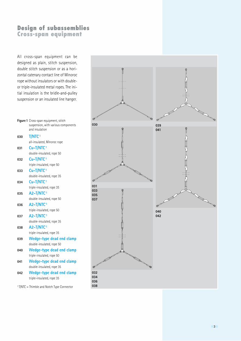
All cross-span equipment can be designed as plain, stitch suspension, double stitch suspension or as a hori-zontal catenary contact line of Minoroc rope without insulators or with double- or triple-insulated metal ropes. The ini-tial insulation is the bridle-and-pulley suspension or an insulated line hanger.
Figure 1 Cross-span equipment, stitch suspension, with various components and insulation
030 T/NTC 1 all-insulated, Minoroc rope
031 Cu-T/NTC 1 double-insulated, rope 50
032 Cu-T/NTC 1 triple-insulated, rope 50
033 Cu-T/NTC 1 double-insulated, rope 35
034 Cu-T/NTC 1 triple-insulated, rope 35
035 A2-T/NTC 1 double-insulated, rope 50
036 A2-T/NTC 1 triple-insulated, rope 50
037 A2-T/NTC 1 double-insulated, rope 35
038 A2-T/NTC 1 triple-insulated, rope 35
039 Wedge-type dead end clamp double-insulated, rope 50
040 Wedge-type dead end clamp triple-insulated, rope 50
041 Wedge-type dead end clamp double-insulated, rope 35
042 Wedge-type dead end clamp triple-insulated, rope 35
1 T/NTC = Thimble and Notch Type Connector
44
140
141
143
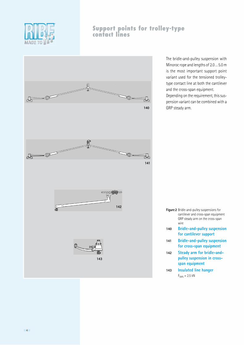
142Figure 2 Bridle-and-pulley suspensions for cantilever and cross-span equipment GRP steady arm on the cross-span wire
140 Bridle-and-pulley suspension for cantilever support141 Bridle-and-pulley suspension for cross-span equipment142 Steady arm for bridle-and- pulley suspension in cross- span equipment143 Insulated line hanger FSMFL = �.5 kN
Support points for trolley-type contact lines
The bridle-and-pulley suspension with Minoroc rope and lengths of �.0 … 5.0 m is the most important support point variant used for the tensioned trolley-type contact line at both the cantilever and the cross-span equipment.Depending on the requirement, this sus-pension variant can be combined with a GRP steady arm.
55
200210
201211
202212
205213
206214
207215
203
204
208
209
Curve pull-offs
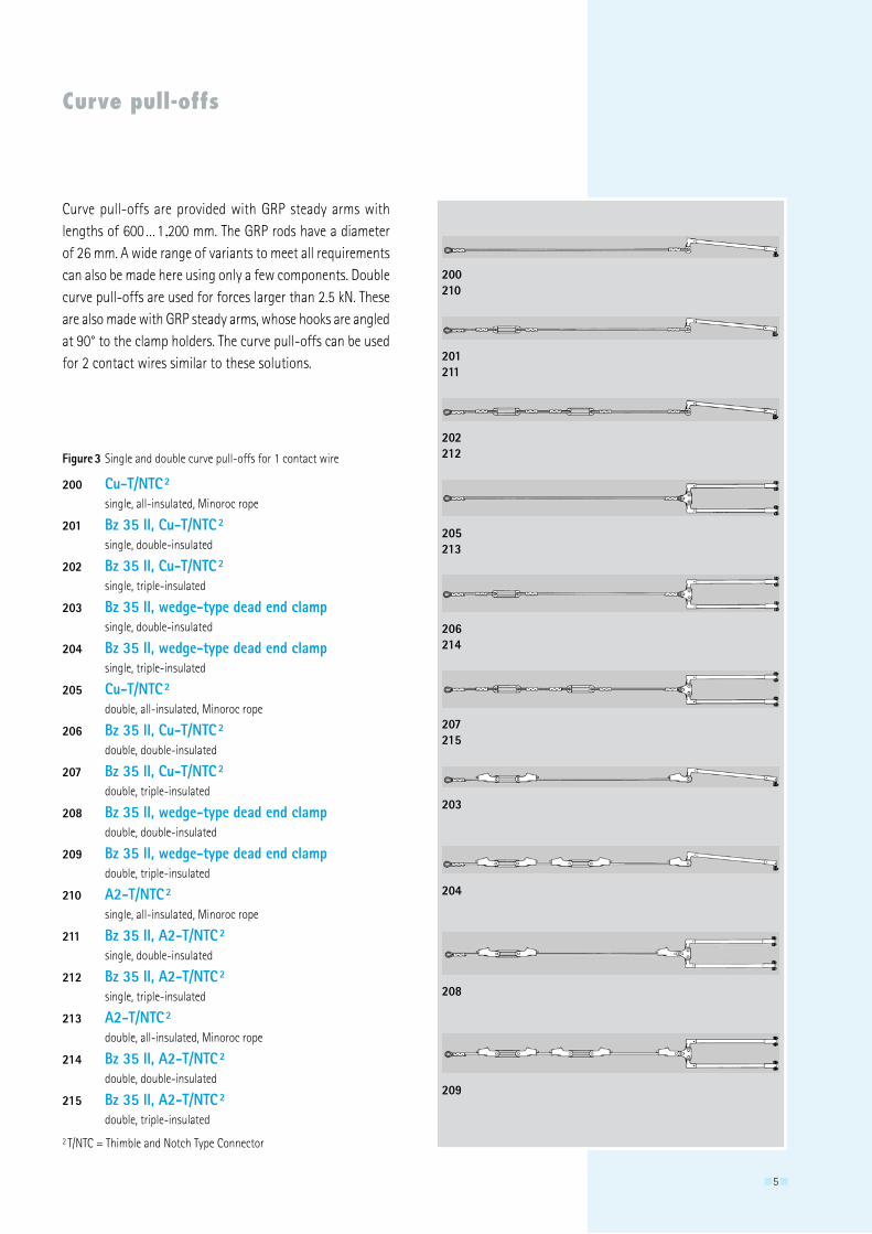
200 Cu-T/NTC 2 single, all-insulated, Minoroc rope
201 Bz 35 II, Cu-T/NTC 2 single, double-insulated
202 Bz 35 II, Cu-T/NTC 2 single, triple-insulated
203 Bz 35 II, wedge-type dead end clamp single, double-insulated
204 Bz 35 II, wedge-type dead end clamp single, triple-insulated
205 Cu-T/NTC 2 double, all-insulated, Minoroc rope
206 Bz 35 II, Cu-T/NTC 2 double, double-insulated
207 Bz 35 II, Cu-T/NTC 2 double, triple-insulated
208 Bz 35 II, wedge-type dead end clamp double, double-insulated
209 Bz 35 II, wedge-type dead end clamp double, triple-insulated
210 A2-T/NTC 2 single, all-insulated, Minoroc rope
211 Bz 35 II, A2-T/NTC 2 single, double-insulated
212 Bz 35 II, A2-T/NTC 2 single, triple-insulated
213 A2-T/NTC 2 double, all-insulated, Minoroc rope
214 Bz 35 II, A2-T/NTC 2 double, double-insulated
215 Bz 35 II, A2-T/NTC 2 double, triple-insulated
� T/NTC = Thimble and Notch Type Connector
Curve pull-offs are provided with GRP steady arms with lengths of 600 … 1,�00 mm. The GRP rods have a diameter of �6 mm. A wide range of variants to meet all requirements can also be made here using only a few components. Double curve pull-offs are used for forces larger than �.5 kN. These are also made with GRP steady arms, whose hooks are angled at 90° to the clamp holders. The curve pull-offs can be used for � contact wires similar to these solutions.
Figure 3 Single and double curve pull-offs for 1 contact wire
66
160
161
162
163
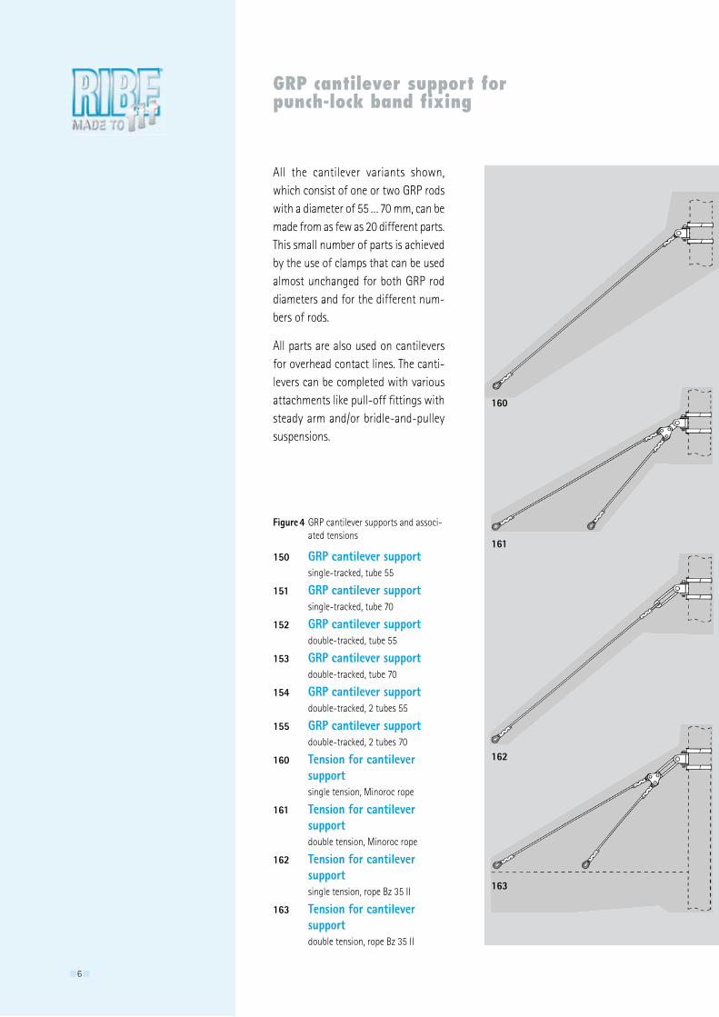
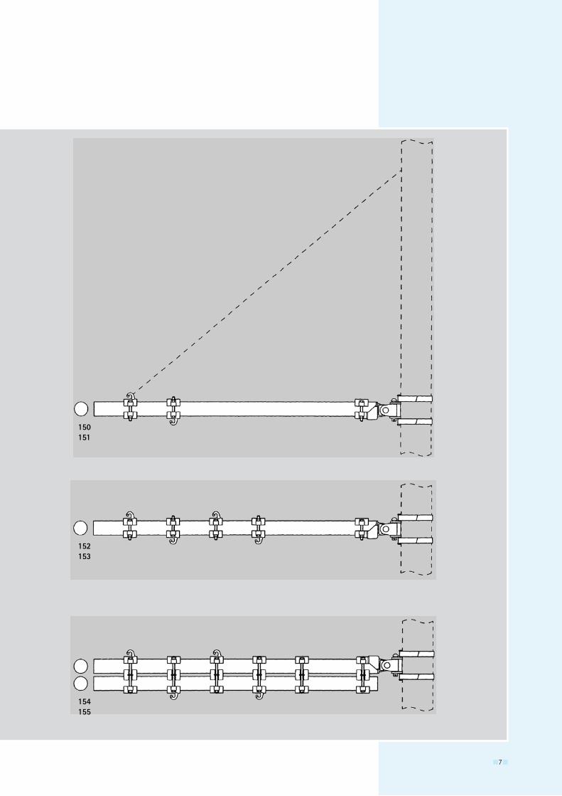
150 GRP cantilever support single-tracked, tube 55
151 GRP cantilever support single-tracked, tube 70
152 GRP cantilever support double-tracked, tube 55
153 GRP cantilever support double-tracked, tube 70
154 GRP cantilever support double-tracked, � tubes 55
155 GRP cantilever support double-tracked, � tubes 70
160 Tension for cantilever support single tension, Minoroc rope
161 Tension for cantilever support double tension, Minoroc rope
162 Tension for cantilever support single tension, rope Bz 35 II
163 Tension for cantilever support double tension, rope Bz 35 II
Figure 4 GRP cantilever supports and associ- ated tensions
GRP cantilever support for punch-lock band fixing
All the cantilever variants shown, which consist of one or two GRP rods with a diameter of 55 … 70 mm, can be made from as few as �0 different parts. This small number of parts is achieved by the use of clamps that can be used almost unchanged for both GRP rod diameters and for the different num-bers of rods.
All parts are also used on cantilevers for overhead contact lines. The canti-levers can be completed with various attachments like pull-off fittings with steady arm and/or bridle-and-pulley suspensions.
77
150151
152153
154155
888
292
291
290
GRP cantilevers for overhead contact lines
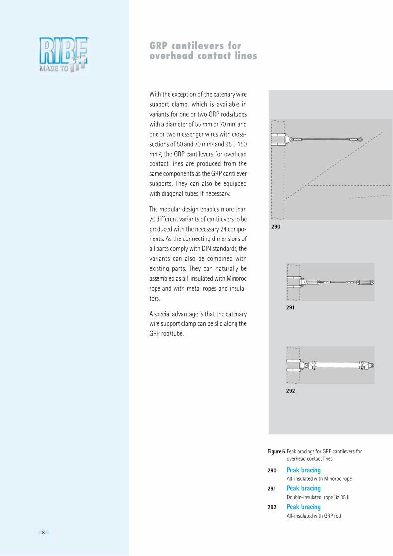
With the exception of the catenary wire support clamp, which is available in variants for one or two GRP rods/tubes with a diameter of 55 mm or 70 mm and one or two messenger wires with cross-sections of 50 and 70 mm² and 95 … 150 mm², the GRP cantilevers for overhead contact lines are produced from the same components as the GRP cantilever supports. They can also be equipped with diagonal tubes if necessary.
The modular design enables more than 70 different variants of cantilevers to be produced with the necessary �4 compo-nents. As the connecting dimensions of all parts comply with DIN standards, the variants can also be combined with existing parts. They can naturally be assembled as all-insulated with Minoroc rope and with metal ropes and insula-tors.
A special advantage is that the catenary wire support clamp can be slid along the GRP rod/tube.
290 Peak bracing All-insulated with Minoroc rope
291 Peak bracing Double-insulated, rope Bz 35 II
292 Peak bracing All-insulated with GRP rod
Figure 5 Peak bracings for GRP cantilevers for overhead contact lines
999
260 - 267 280 - 287
270 - 277
250 - 257
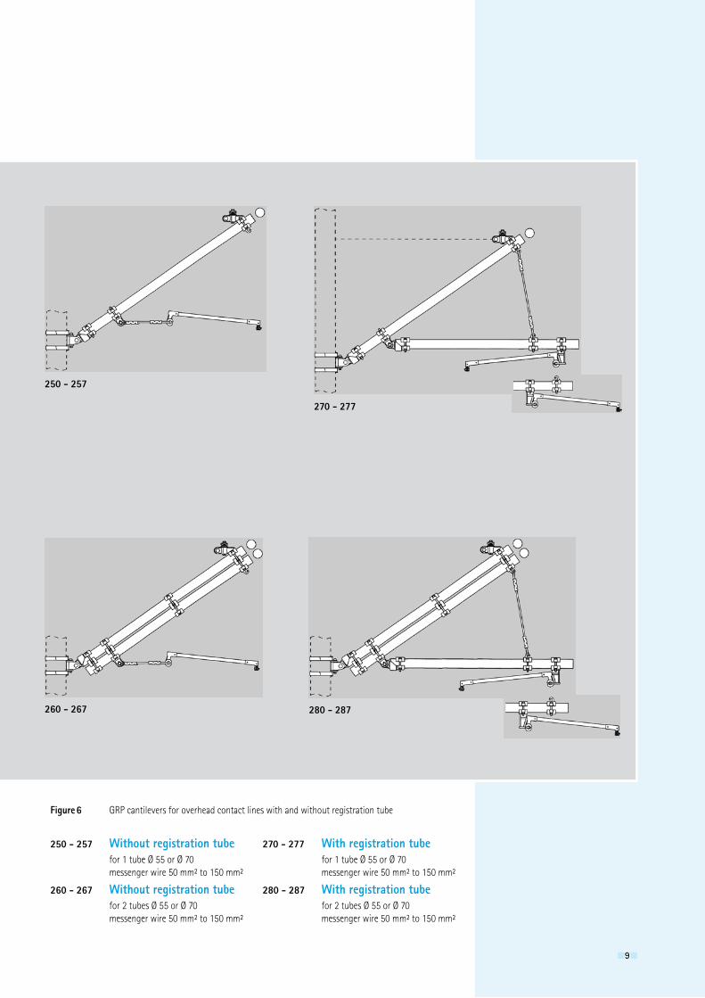
250 - 257 Without registration tube for 1 tube Ø 55 or Ø 70 messenger wire 50 mm² to 150 mm²
260 - 267 Without registration tube for � tubes Ø 55 or Ø 70 messenger wire 50 mm² to 150 mm²
Figure 6 GRP cantilevers for overhead contact lines with and without registration tube
270 - 277 With registration tube for 1 tube Ø 55 or Ø 70 messenger wire 50 mm² to 150 mm²
280 - 287 With registration tube for � tubes Ø 55 or Ø 70 messenger wire 50 mm² to 150 mm²
101010
Overview of components
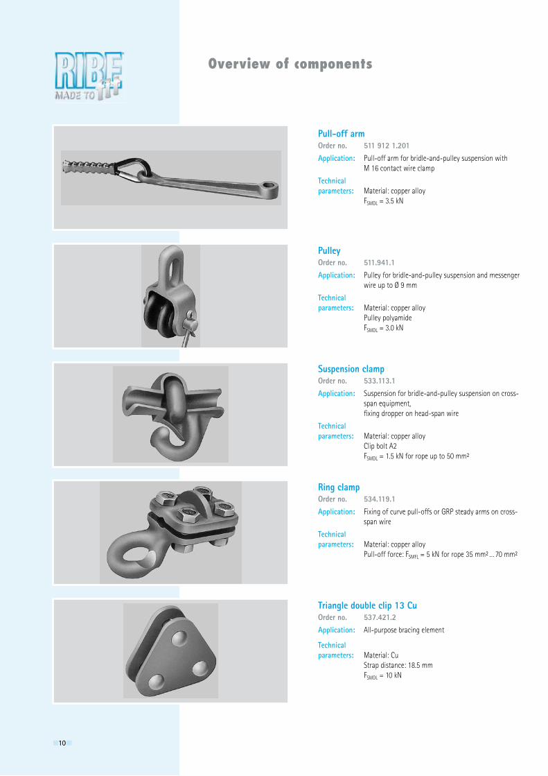
Pull-off armOrder no. 511 912 1.201Application: Pull-off arm for bridle-and-pulley suspension with M 16 contact wire clamp
Technical parameters: Material: copper alloy FSMDL = 3.5 kN
PulleyOrder no. 511.941.1Application: Pulley for bridle-and-pulley suspension and messenger wire up to Ø 9 mm
Technical parameters: Material: copper alloy Pulley polyamide FSMDL = 3.0 kN
Suspension clampOrder no. 533.113.1Application: Suspension for bridle-and-pulley suspension on cross- span equipment, fixing dropper on head-span wire
Technical parameters: Material: copper alloy Clip bolt A� FSMDL = 1.5 kN for rope up to 50 mm²
Ring clampOrder no. 534.119.1Application: Fixing of curve pull-offs or GRP steady arms on cross- span wire
Technical parameters: Material: copper alloy Pull-off force: FSMFL = 5 kN for rope 35 mm² … 70 mm²
Triangle double clip 13 CuOrder no. 537.421.2Application: All-purpose bracing element
Technical parameters: Material: Cu Strap distance: 18.5 mm FSMDL = 10 kN
111111
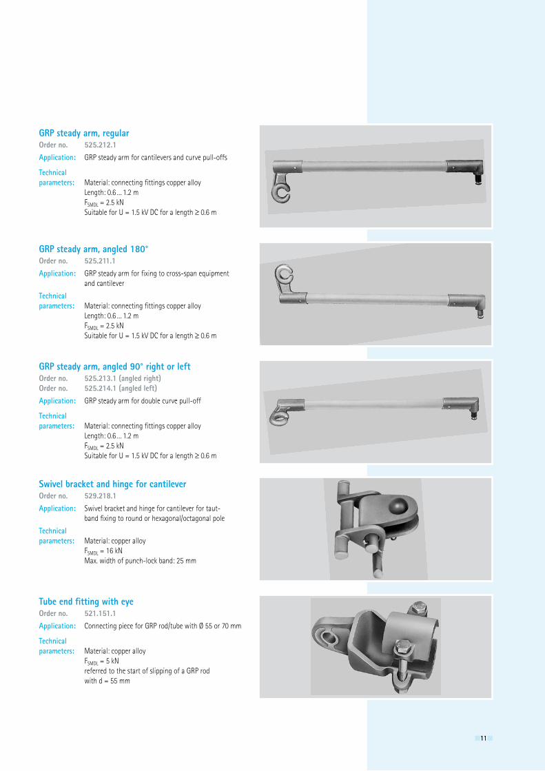
GRP steady arm, regularOrder no. 525.212.1Application: GRP steady arm for cantilevers and curve pull-offs
Technicalparameters: Material: connecting fittings copper alloy Length: 0.6 … 1.� m FSMDL = �.5 kN Suitable for U = 1.5 kV DC for a length ≥ 0.6 m
GRP steady arm, angled 180°Order no. 525.211.1Application: GRP steady arm for fixing to cross-span equipment and cantilever
Technical parameters: Material: connecting fittings copper alloy Length: 0.6 … 1.� m FSMDL = �.5 kN Suitable for U = 1.5 kV DC for a length ≥ 0.6 m
GRP steady arm, angled 90° right or leftOrder no. 525.213.1 (angled right)Order no. 525.214.1 (angled left)Application: GRP steady arm for double curve pull-off
Technical parameters: Material: connecting fittings copper alloy Length: 0.6 … 1.� m FSMDL = �.5 kN Suitable for U = 1.5 kV DC for a length ≥ 0.6 m
Swivel bracket and hinge for cantileverOrder no. 529.218.1Application: Swivel bracket and hinge for cantilever for taut- band fixing to round or hexagonal/octagonal pole
Technical parameters: Material: copper alloy FSMDL = 16 kN Max. width of punch-lock band: �5 mm
Tube end fitting with eyeOrder no. 521.151.1Application: Connecting piece for GRP rod/tube with Ø 55 or 70 mm
Technical parameters: Material: copper alloy FSMDL = 5 kN referred to the start of slipping of a GRP rod with d = 55 mm
1�1�1�
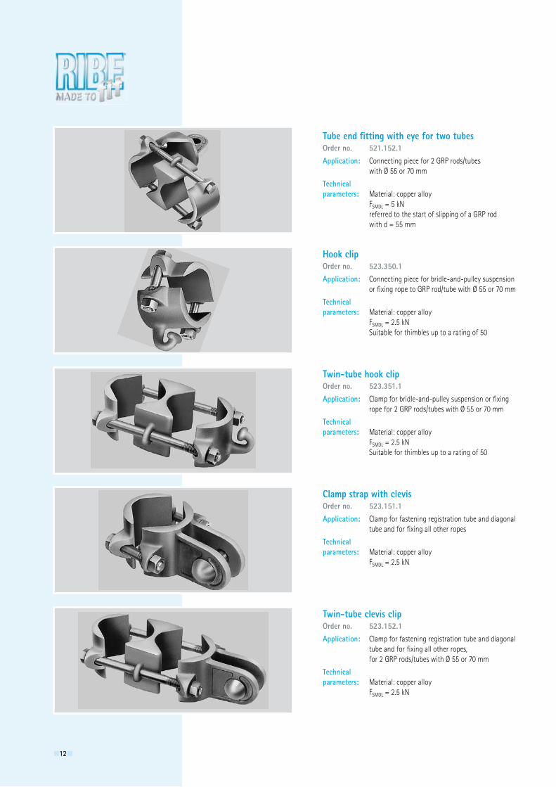
Tube end fitting with eye for two tubesOrder no. 521.152.1Application: Connecting piece for � GRP rods/tubes with Ø 55 or 70 mm
Technical parameters: Material: copper alloy FSMDL = 5 kN referred to the start of slipping of a GRP rod with d = 55 mm
Hook clipOrder no. 523.350.1Application: Connecting piece for bridle-and-pulley suspension or fixing rope to GRP rod/tube with Ø 55 or 70 mm
Technical parameters: Material: copper alloy FSMDL = �.5 kN Suitable for thimbles up to a rating of 50
Twin-tube hook clipOrder no. 523.351.1Application: Clamp for bridle-and-pulley suspension or fixing rope for � GRP rods/tubes with Ø 55 or 70 mm
Technical parameters: Material: copper alloy FSMDL = �.5 kN Suitable for thimbles up to a rating of 50
Clamp strap with clevisOrder no. 523.151.1Application: Clamp for fastening registration tube and diagonal tube and for fixing all other ropes
Technical parameters: Material: copper alloy FSMDL = �.5 kN
Twin-tube clevis clipOrder no. 523.152.1Application: Clamp for fastening registration tube and diagonal tube and for fixing all other ropes, for � GRP rods/tubes with Ø 55 or 70 mm
Technical parameters: Material: copper alloy FSMDL = �.5 kN
131313
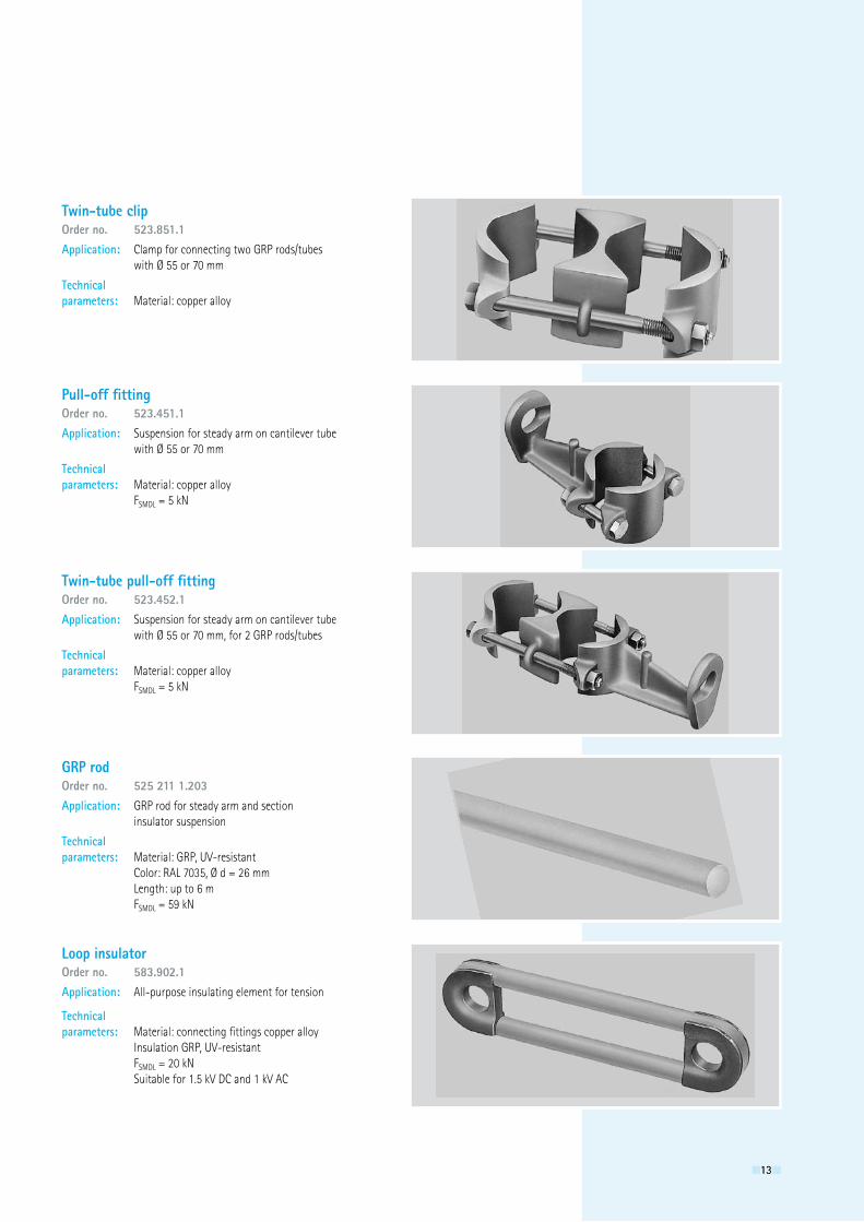
Twin-tube clipOrder no. 523.851.1Application: Clamp for connecting two GRP rods/tubes with Ø 55 or 70 mm
Technical parameters: Material: copper alloy
Pull-off fittingOrder no. 523.451.1Application: Suspension for steady arm on cantilever tube with Ø 55 or 70 mm
Technical parameters: Material: copper alloy FSMDL = 5 kN
Twin-tube pull-off fittingOrder no. 523.452.1Application: Suspension for steady arm on cantilever tube with Ø 55 or 70 mm, for � GRP rods/tubes
Technical parameters: Material: copper alloy FSMDL = 5 kN
GRP rodOrder no. 525 211 1.203Application: GRP rod for steady arm and section insulator suspension
Technical parameters: Material: GRP, UV-resistant Color: RAL 7035, Ø d = �6 mm Length: up to 6 m FSMDL = 59 kN
Loop insulatorOrder no. 583.902.1Application: All-purpose insulating element for tension
Technical parameters: Material: connecting fittings copper alloy Insulation GRP, UV-resistant FSMDL = �0 kN Suitable for 1.5 kV DC and 1 kV AC
141414
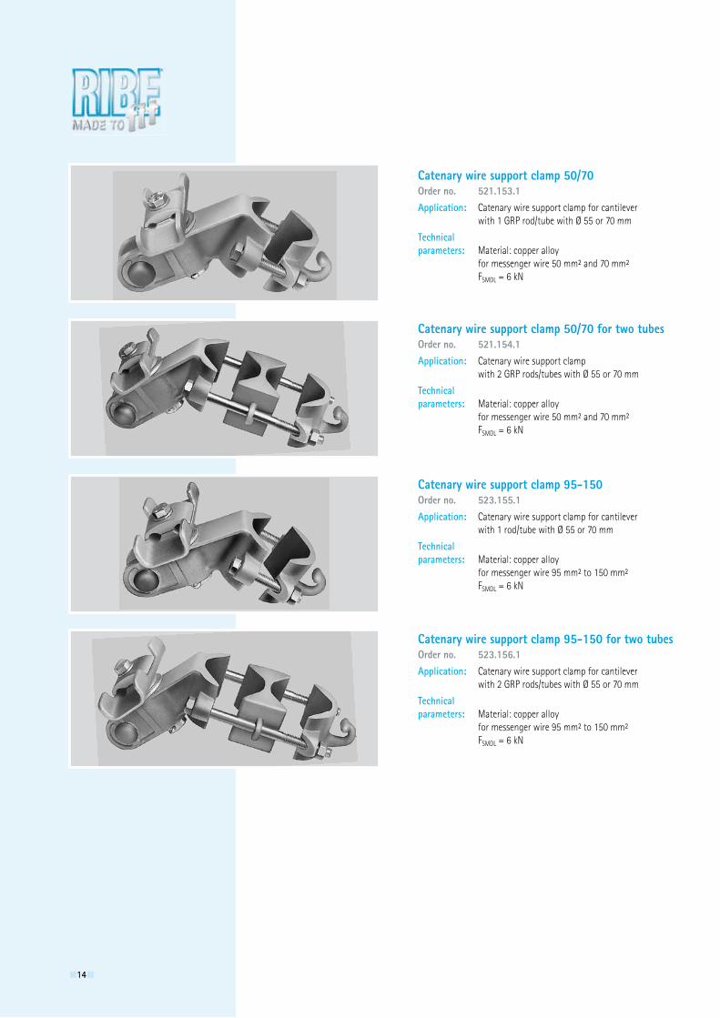
Catenary wire support clamp 50/70Order no. 521.153.1Application: Catenary wire support clamp for cantilever with 1 GRP rod/tube with Ø 55 or 70 mm
Technical parameters: Material: copper alloy for messenger wire 50 mm² and 70 mm² FSMDL = 6 kN
Catenary wire support clamp 50/70 for two tubesOrder no. 521.154.1Application: Catenary wire support clamp with � GRP rods/tubes with Ø 55 or 70 mm
Technical parameters: Material: copper alloy for messenger wire 50 mm² and 70 mm² FSMDL = 6 kN
Catenary wire support clamp 95-150Order no. 523.155.1Application: Catenary wire support clamp for cantilever with 1 rod/tube with Ø 55 or 70 mm
Technical parameters: Material: copper alloy for messenger wire 95 mm² to 150 mm² FSMDL = 6 kN
Catenary wire support clamp 95-150 for two tubesOrder no. 523.156.1Application: Catenary wire support clamp for cantilever with � GRP rods/tubes with Ø 55 or 70 mm
Technical parameters: Material: copper alloy for messenger wire 95 mm² to 150 mm² FSMDL = 6 kN
151515
L1
Ø 14 Ø 13
L2
L3
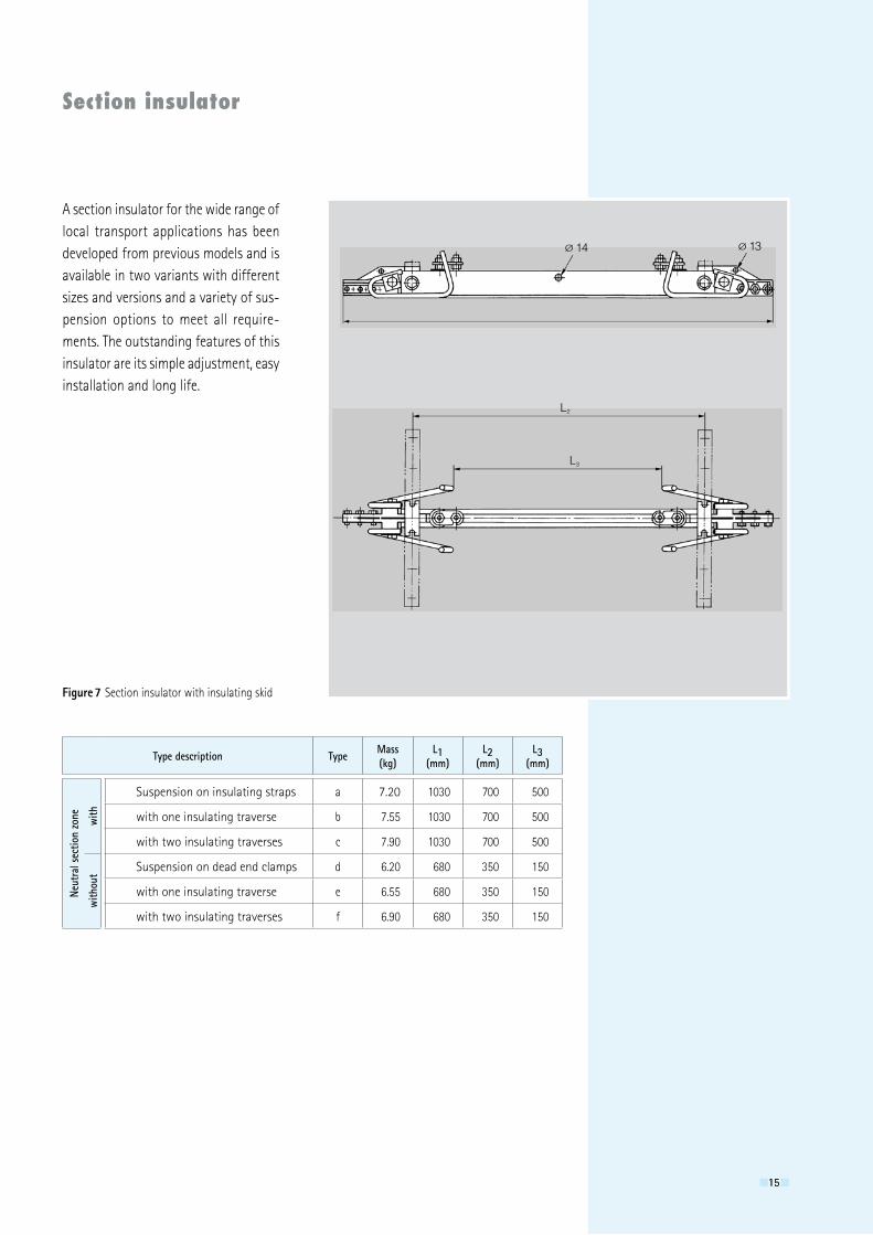
Section insulator
Figure 7 Section insulator with insulating skid
Type description Type Mass(kg)
L1(mm)
L2(mm)
L3(mm)
Neut
ral s
ectio
n zo
ne with
Suspension on insulating straps a 7.�0 1030 700 500
with one insulating traverse b 7.55 1030 700 500
with two insulating traverses c 7.90 1030 700 500
with
out Suspension on dead end clamps d 6.�0 680 350 150
with one insulating traverse e 6.55 680 350 150
with two insulating traverses f 6.90 680 350 150
A section insulator for the wide range of local transport applications has been developed from previous models and is available in two variants with different sizes and versions and a variety of sus-pension options to meet all require-ments. The outstanding features of this insulator are its simple adjustment, easy installation and long life.
161616
L2
70025
4L1
Ø 14 Ø 13
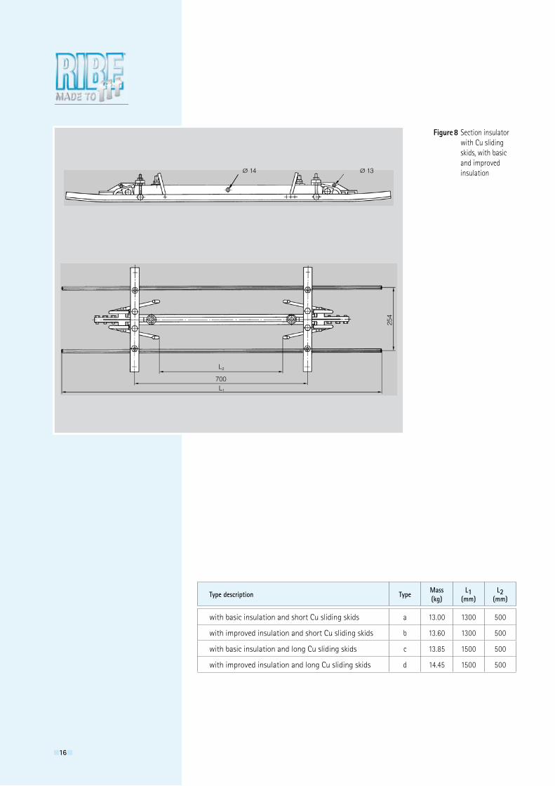
Figure 8 Section insulator with Cu sliding skids, with basic and improved insulation
Type description Type Mass(kg)
L1(mm)
L2(mm)
with basic insulation and short Cu sliding skids a 13.00 1300 500
with improved insulation and short Cu sliding skids b 13.60 1300 500
with basic insulation and long Cu sliding skids c 13.85 1500 500
with improved insulation and long Cu sliding skids d 14.45 1500 500
171717
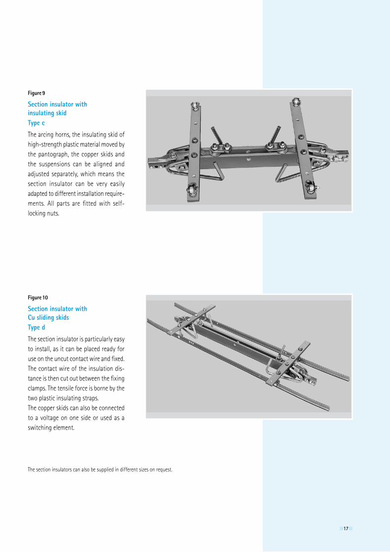
Section insulator with insulating skidType c
The arcing horns, the insulating skid of high-strength plastic material moved by the pantograph, the copper skids and the suspensions can be aligned and adjusted separately, which means the section insulator can be very easily adapted to different installation require-ments. All parts are fitted with self- locking nuts.
The section insulators can also be supplied in different sizes on request.
Figure 9
Section insulator with Cu sliding skidsType d
The section insulator is particularly easy to install, as it can be placed ready for use on the uncut contact wire and fixed. The contact wire of the insulation dis-tance is then cut out between the fixing clamps. The tensile force is borne by the two plastic insulating straps.The copper skids can also be connected to a voltage on one side or used as a switching element.
Figure 10
181818
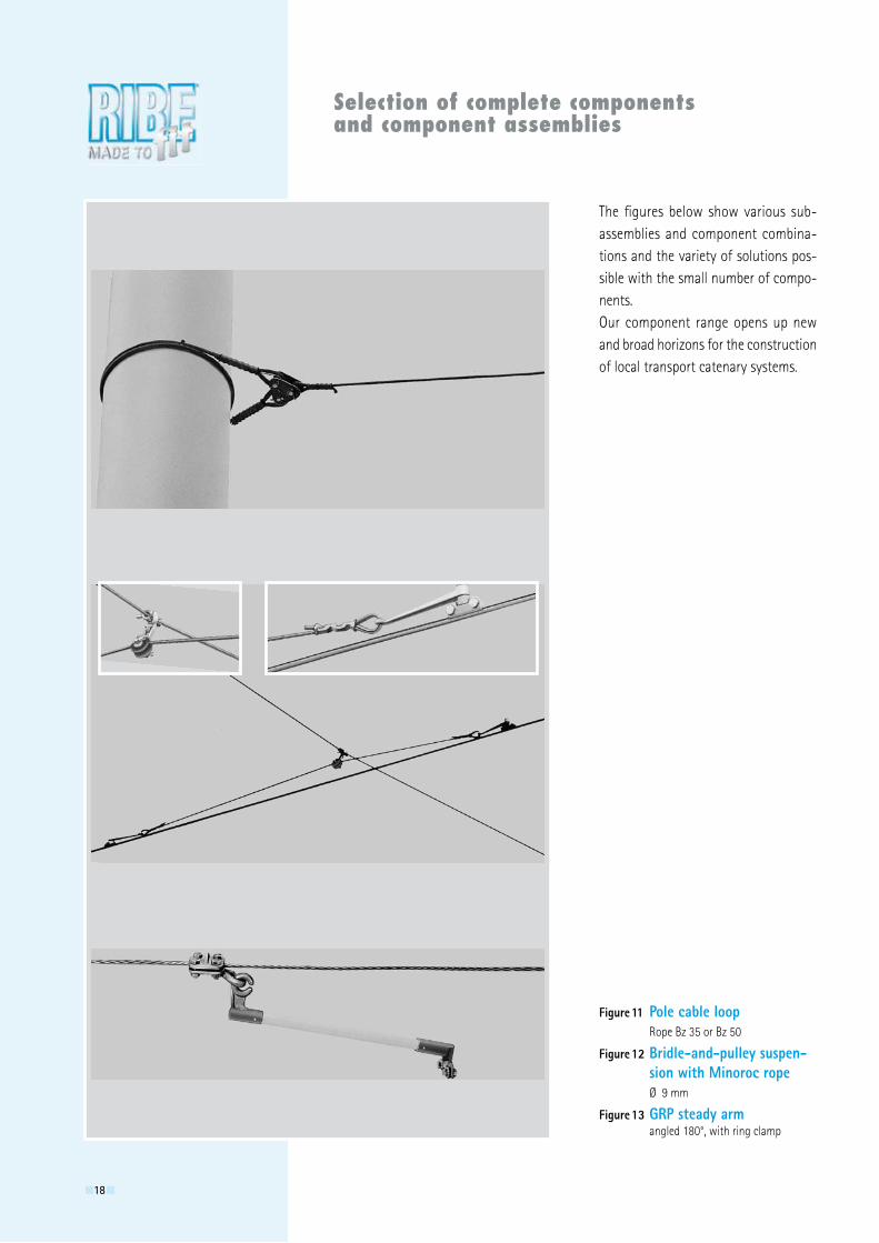
Selection of complete components and component assemblies
The figures below show various sub-assemblies and component combina-tions and the variety of solutions pos-sible with the small number of compo-nents.Our component range opens up new and broad horizons for the construction of local transport catenary systems.
Figure 11 Pole cable loop Rope Bz 35 or Bz 50
Figure 12 Bridle-and-pulley suspen- sion with Minoroc rope Ø 9 mm
Figure 13 GRP steady arm angled 180°, with ring clamp
191919
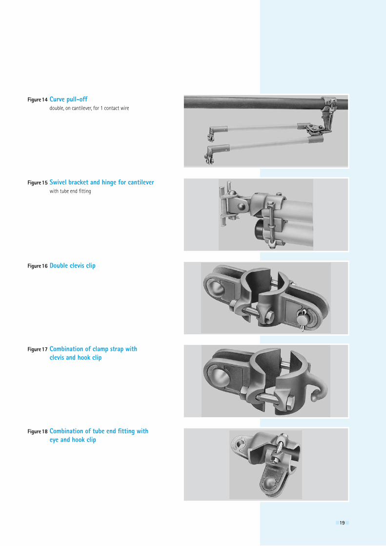
Figure 14 Curve pull-off double, on cantilever, for 1 contact wire
Figure 15 Swivel bracket and hinge for cantilever with tube end fitting
Figure 16 Double clevis clip
Figure 17 Combination of clamp strap with clevis and hook clip
Figure 18 Combination of tube end fitting with eye and hook clip

Richard Bergner Elektroarmaturen GmbH & Co. KGBahnhofstr. 8-16 · 91126 Schwabach · Germany · Telephone +49 91 22 / 87-0 · Fax +49 91 22 / 87-15 06
E-mail [email protected] / [email protected] · Internet www.ribe.de EL/1
16/0
2/07
04/0
.5/p
m
©
Ric
hard
Ber
gner
Ele
ktro
arm
atur
en G
mbH
& C
o. K
G
CM
B