caterpillar - maintenance interval schedule
DESCRIPTION
Operation and Maintenance Manual of G3600 EnginesTRANSCRIPT

®© 2010 CaterpillarAll Rights Reserved
®
MAINTENANCE INTERVALSOperation and Maintenance Manual Excerpt
SEBU7563-09April 2010
Operation andMaintenanceManualG3600 EnginesBLB1-Up (Engine)BKE1-Up (Engine)BEN1-Up (Engine)4ZS1-Up (Engine)
SAFETY.CAT.COM

60 SEBU7563-09Maintenance SectionMaintenance Interval Schedule
i03915129
Maintenance Interval Schedule(G3600 Engines That UseWellhead or Natural Gas andHave a Compression Ratio of9.2:1)SMCS Code: 1000; 4450; 7500
Ensure that all safety information, warnings,and instructions are read and understood beforeany operation or any maintenance proceduresare performed. The user is responsible for theperformance of all maintenance including thefollowing procedures: all adjustments, the use ofproper lubricants, fluids, filters, and the installationof new components due to normal wear and aging .The performance of this product may be diminished ifproper maintenance intervals and procedures are notfollowed. Components may experience acceleratedwear if proper maintenance intervals and proceduresare not followed.
Note: Use whichever of the following that occursfirst in order to determine the maintenance intervals:fuel consumption, service hours, and calendar time. Before each consecutive interval is performed, allmaintenance from the previous intervals must beperformed.
Products that operate in severe operating conditionsmay require more frequent maintenance.
When Required
Actuator Control Linkage - Replace ...................... 66Barring Device - Lubricate .................................... 69Cooling System Coolant Sample (Level 2) -Obtain ................................................................. 77Engine Air Cleaner Element (Single Element) -Clean/Replace .................................................... 87Engine Air Precleaner - Clean .............................. 91Overhaul Considerations ..................................... 116Valve Stem Projection - Measure/Record ........... 122
Daily
Air Starting Motor Lubricator Oil Level - Check .... 68Air Tank Moisture and Sediment - Drain ............... 69Control Panel - Inspect ......................................... 74Cooling System Coolant Level - Check ................ 76Driven Equipment - Inspect/Replace/Lubricate ... 83Electrohydraulic System - Inspect ........................ 86Engine Oil Level - Check ...................................... 96Fuel System Fuel Filter Differential Pressure -Check ................................................................ 103Walk-Around Inspection ...................................... 123
Every 250 Service Hours
Battery Electrolyte Level - Check .......................... 71Cooling System Coolant Sample (Level 1) -Obtain ................................................................. 77Cooling System Supplemental Coolant Additive(SCA) - Test/Add ................................................. 78Engine Oil Sample - Obtain .................................. 97
Initial 1000 Service Hours
Air Starting Motor Lines Screen - Clean ............... 67Air Starting Motor Lubricator Bowl - Clean ........... 67Crankcase Blowby - Measure/Record .................. 80Cylinder Pressure - Measure/Record ................... 81Electrohydraulic System Oil Filter - Change ......... 87Engine Crankcase Breather - Clean ..................... 91Engine Protective Device Connections - Inspect .. 98Engine Speed/Timing Sensor - Clean/Inspect .... 100Engine Valve Lash - Inspect/Adjust .................... 101Engine Valve Rotators - Inspect ......................... 102Valve Stem Projection - Measure/Record ........... 122
Every 1000 Service Hours
Actuator Control Linkage - Lubricate .................... 66Belts - Inspect/Adjust/Replace .............................. 71Hoses and Clamps - Inspect/Replace ................ 105Ignition System Spark Plugs - Check/Adjust ...... 108
Every 2000 Service Hours
Aftercooler Condensation - Drain ......................... 67Cooling System Coolant Sample (Level 2) -Obtain ................................................................. 77Crankshaft Vibration Damper - Inspect ................. 80Engine Crankcase Breather - Clean ..................... 91Engine Mounts - Check ........................................ 92Engine Valve Lash - Inspect/Adjust .................... 101Engine Valve Rotators - Inspect ......................... 102Valve Stem Projection - Measure/Record ........... 122
Every 5000 Service Hours
Air Starting Motor Lines Screen - Clean ............... 67Air Starting Motor Lubricator Bowl - Clean ........... 67Combustion Sensor - Clean/Inspect/Replace ....... 72Cooling System Level Switch - Inspect ................. 77Crankcase Blowby - Measure/Record .................. 80Cylinder Pressure - Measure/Record ................... 81Driven Equipment - Check .................................... 82Electrohydraulic System - Check/Adjust ............... 85Electrohydraulic System Oil - Change .................. 86Electrohydraulic System Oil Filter - Change ......... 87Engine Oil - Change ............................................. 92Engine Oil Filter - Change .................................... 93Engine Protective Device Connections - Inspect .. 98Engine Protective Devices - Check .................... 100Exhaust Bypass - Recondition ............................ 102Gas Shutoff Valve - Inspect ................................ 105Ignition System Spark Plugs - Replace ............... 111Inlet Air System - Inspect ..................................... 111
SEBU7563-09 61Maintenance Section
Maintenance Interval Schedule
Inlet Gas Manifold and Piping - Inspect/Replace .. 111Prechamber Check Valves - Clean ...................... 118Starting Motor - Inspect ....................................... 119Turbocharger - Inspect ........................................ 121
Every 10 000 Service Hours
Alternator - Inspect ............................................... 69Cooling System Water Temperature Regulator -Replace ............................................................... 79Electrohydraulic Actuator - Inspect ....................... 83Engine Oil Temperature Regulator - Replace ....... 98Engine Speed/Timing Sensor - Clean/Inspect .... 100Exhaust Shields - Inspect ................................... 102Gas Pressure Regulator - Inspect/Replace ........ 104Prechamber Check Valves - Replace .................. 119Prelube Pump - Inspect ....................................... 119Water Pump - Inspect ......................................... 124
Every 20 000 Service Hours or 3 Years
Cooling System Coolant (NGEC) - Change .......... 74
Every 25 000 Service Hours
Gas Admission Valve Seals - Inspect/Replace ... 104Overhaul (Top End) .............................................. 114Prechamber - Clean/Inspect ................................ 118
Every 50 000 Service Hours
Electrohydraulic Actuator - Recondition ................ 84Gas Admission Valve - Recondition .................... 103Overhaul (In-Frame) ............................................ 112
Every 100 000 Service Hours
Overhaul (Major) .................................................. 113
62 SEBU7563-09Maintenance SectionMaintenance Interval Schedule
i03915106
Maintenance Interval Schedule(G3600 Engines That UseNatural Gas and Have aCompression Ratio of 10.5:1or 11:1)SMCS Code: 1000; 4450; 7500
Ensure that all safety information, warnings,and instructions are read and understood beforeany operation or any maintenance proceduresare performed. The user is responsible for theperformance of all maintenance including thefollowing procedures: all adjustments, the use ofproper lubricants, fluids, filters, and the installationof new components due to normal wear and aging .The performance of this product may be diminished ifproper maintenance intervals and procedures are notfollowed. Components may experience acceleratedwear if proper maintenance intervals and proceduresare not followed.
Note: Use whichever of the following that occursfirst in order to determine the maintenance intervals:fuel consumption, service hours, and calendar time. Before each consecutive interval is performed, allmaintenance from the previous intervals must beperformed.
Products that operate in severe operating conditionsmay require more frequent maintenance.
When Required
Actuator Control Linkage - Replace ...................... 66Barring Device - Lubricate .................................... 69Cooling System Coolant Sample (Level 2) -Obtain ................................................................. 77Engine Air Cleaner Element (Single Element) -Clean/Replace .................................................... 87Engine Air Precleaner - Clean .............................. 91Overhaul Considerations ..................................... 116Valve Stem Projection - Measure/Record ........... 122
Daily
Air Starting Motor Lubricator Oil Level - Check .... 68Air Tank Moisture and Sediment - Drain ............... 69Control Panel - Inspect ......................................... 74Cooling System Coolant Level - Check ................ 76Driven Equipment - Inspect/Replace/Lubricate ... 83Electrohydraulic System - Inspect ........................ 86Engine Oil Level - Check ...................................... 96Fuel System Fuel Filter Differential Pressure -Check ................................................................ 103Walk-Around Inspection ...................................... 123
Every 250 Service Hours
Battery Electrolyte Level - Check .......................... 71Cooling System Coolant Sample (Level 1) -Obtain ................................................................. 77Cooling System Supplemental Coolant Additive(SCA) - Test/Add ................................................. 78Engine Oil Sample - Obtain .................................. 97
Initial 1000 Service Hours
Air Starting Motor Lines Screen - Clean ............... 67Air Starting Motor Lubricator Bowl - Clean ........... 67Crankcase Blowby - Measure/Record .................. 80Cylinder Pressure - Measure/Record ................... 81Electrohydraulic System Oil Filter - Change ......... 87Engine Crankcase Breather - Clean ..................... 91Engine Protective Device Connections - Inspect .. 98Engine Speed/Timing Sensor - Clean/Inspect .... 100Engine Valve Lash - Inspect/Adjust .................... 101Engine Valve Rotators - Inspect ......................... 102Valve Stem Projection - Measure/Record ........... 122
Every 1000 Service Hours
Actuator Control Linkage - Lubricate .................... 66Belts - Inspect/Adjust/Replace .............................. 71Hoses and Clamps - Inspect/Replace ................ 105Ignition System Spark Plugs - Replace ............... 111
Every 2000 Service Hours
Aftercooler Condensation - Drain ......................... 67Cooling System Coolant Sample (Level 2) -Obtain ................................................................. 77Crankshaft Vibration Damper - Inspect ................. 80Engine Crankcase Breather - Clean ..................... 91Engine Mounts - Check ........................................ 92Engine Valve Lash - Inspect/Adjust .................... 101Engine Valve Rotators - Inspect ......................... 102Valve Stem Projection - Measure/Record ........... 122
Every 5000 Service Hours
Air Starting Motor Lines Screen - Clean ............... 67Air Starting Motor Lubricator Bowl - Clean ........... 67Combustion Sensor - Clean/Inspect/Replace ....... 72Cooling System Level Switch - Inspect ................. 77Crankcase Blowby - Measure/Record .................. 80Cylinder Pressure - Measure/Record ................... 81Driven Equipment - Check .................................... 82Electrohydraulic System - Check/Adjust ............... 85Electrohydraulic System Oil - Change .................. 86Electrohydraulic System Oil Filter - Change ......... 87Engine Oil - Change ............................................. 92Engine Oil Filter - Change .................................... 93Engine Protective Device Connections - Inspect .. 98Engine Protective Devices - Check .................... 100Exhaust Bypass - Recondition ............................ 102Gas Shutoff Valve - Inspect ................................ 105Inlet Air System - Inspect ..................................... 111Inlet Gas Manifold and Piping - Inspect/Replace .. 111
SEBU7563-09 63Maintenance Section
Maintenance Interval Schedule
Prechamber Check Valves - Clean ...................... 118Starting Motor - Inspect ....................................... 119Turbocharger - Inspect ........................................ 121
Every 10 000 Service Hours
Alternator - Inspect ............................................... 69Cooling System Water Temperature Regulator -Replace ............................................................... 79Electrohydraulic Actuator - Inspect ....................... 83Engine Oil Temperature Regulator - Replace ....... 98Engine Speed/Timing Sensor - Clean/Inspect .... 100Exhaust Shields - Inspect ................................... 102Gas Pressure Regulator - Inspect/Replace ........ 104Prechamber Check Valves - Replace .................. 119Prelube Pump - Inspect ....................................... 119Water Pump - Inspect ......................................... 124
Every 15 000 Service Hours
Gas Admission Valve Seals - Inspect/Replace ... 104Overhaul (Top End) .............................................. 114Prechamber - Clean/Inspect ................................ 118
Every 20 000 Service Hours or 3 Years
Cooling System Coolant (NGEC) - Change .......... 74
Between 45 000 and 48 000 Service Hours
Electrohydraulic Actuator - Recondition ................ 84Gas Admission Valve - Recondition .................... 103Overhaul (In-Frame) ............................................ 112
Between 75 000 and 80 000 Service Hours
Overhaul (Major) .................................................. 113
64 SEBU7563-09Maintenance SectionMaintenance Interval Schedule
i03915101
Maintenance Interval Schedule(G3600 Engines That useBio-Gas)SMCS Code: 1000; 4450; 7500
Ensure that all safety information, warnings,and instructions are read and understood beforeany operation or any maintenance proceduresare performed. The user is responsible for theperformance of all maintenance including thefollowing procedures: all adjustments, the use ofproper lubricants, fluids, filters, and the installationof new components due to normal wear and aging .The performance of this product may be diminished ifproper maintenance intervals and procedures are notfollowed. Components may experience acceleratedwear if proper maintenance intervals and proceduresare not followed.
Note: Use whichever of the following that occursfirst in order to determine the maintenance intervals:fuel consumption, service hours, and calendar time. Before each consecutive interval is performed, allmaintenance from the previous intervals must beperformed.
Products that operate in severe operating conditionsmay require more frequent maintenance.
When Required
Actuator Control Linkage - Replace ...................... 66Barring Device - Lubricate .................................... 69Cooling System Coolant Sample (Level 2) -Obtain ................................................................. 77Engine Air Cleaner Element (Single Element) -Clean/Replace .................................................... 87Engine Air Precleaner - Clean .............................. 91Engine Oil - Change ............................................. 92Engine Oil Filter - Change .................................... 93Overhaul Considerations ..................................... 116Valve Stem Projection - Measure/Record ........... 122
Daily
Air Starting Motor Lubricator Oil Level - Check .... 68Air Tank Moisture and Sediment - Drain ............... 69Control Panel - Inspect ......................................... 74Cooling System Coolant Level - Check ................ 76Driven Equipment - Inspect/Replace/Lubricate ... 83Electrohydraulic System - Inspect ........................ 86Engine Air Cleaner Service Indicator - Inspect ..... 90Engine Oil Level - Check ...................................... 96Fuel System Fuel Filter Differential Pressure -Check ................................................................ 103Turbocharger - Clean .......................................... 120Walk-Around Inspection ...................................... 123
Every 125 Service Hours
Engine Oil Sample - Obtain .................................. 97
Every 250 Service Hours
Battery Electrolyte Level - Check .......................... 71Cooling System Coolant Sample (Level 1) -Obtain ................................................................. 77Cooling System Supplemental Coolant Additive(SCA) - Test/Add ................................................. 78
Initial 1000 Service Hours
Air Starting Motor Lines Screen - Clean ............... 67Air Starting Motor Lubricator Bowl - Clean ........... 67Crankcase Blowby - Measure/Record .................. 80Cylinder Pressure - Measure/Record ................... 81Electrohydraulic System Oil Filter - Change ......... 87Engine Crankcase Breather - Clean ..................... 91Engine Protective Device Connections - Inspect .. 98Engine Speed/Timing Sensor - Clean/Inspect .... 100Engine Valve Lash - Inspect/Adjust .................... 101Engine Valve Rotators - Inspect ......................... 102Valve Stem Projection - Measure/Record ........... 122
Every 1000 Service Hours
Actuator Control Linkage - Lubricate .................... 66Belts - Inspect/Adjust/Replace .............................. 71Combustion Sensor - Clean/Inspect/Replace ....... 72Hoses and Clamps - Inspect/Replace ................ 105Ignition System Spark Plugs - Replace ............... 111Prechamber Check Valves - Clean ...................... 118
Every 2000 Service Hours
Aftercooler Condensation - Drain ......................... 67Cooling System Coolant Sample (Level 2) -Obtain ................................................................. 77Crankshaft Vibration Damper - Inspect ................. 80Cylinders - Inspect ................................................ 82Engine Crankcase Breather - Clean ..................... 91Engine Mounts - Check ........................................ 92Engine Valve Lash - Inspect/Adjust .................... 101Engine Valve Rotators - Inspect ......................... 102Valve Stem Projection - Measure/Record ........... 122
Every 5000 Service Hours
Air Starting Motor Lines Screen - Clean ............... 67Air Starting Motor Lubricator Bowl - Clean ........... 67Cooling System Level Switch - Inspect ................. 77Crankcase Blowby - Measure/Record .................. 80Cylinder Pressure - Measure/Record ................... 81Driven Equipment - Check .................................... 82Electrohydraulic System - Check/Adjust ............... 85Electrohydraulic System Oil - Change .................. 86Electrohydraulic System Oil Filter - Change ......... 87Engine Protective Device Connections - Inspect .. 98Engine Protective Devices - Check .................... 100Exhaust Bypass - Recondition ............................ 102Gas Shutoff Valve - Inspect ................................ 105

SEBU7563-09 65Maintenance Section
Maintenance Interval Schedule
Inlet Air System - Inspect ..................................... 111Inlet Gas Manifold and Piping - Inspect/Replace .. 111Prechamber Check Valves - Replace .................. 119Starting Motor - Inspect ....................................... 119Turbocharger - Inspect ........................................ 121Turbocharger Cleaner Tube - Replace ............... 122
Between 10 000 and 14 000 Service Hours
Gas Admission Valve Seals - Inspect/Replace ... 104Overhaul (Top End) .............................................. 114Prechamber - Clean/Inspect ................................ 118
Every 10 000 Service Hours
Alternator - Inspect ............................................... 69Cooling System Water Temperature Regulator -Replace ............................................................... 79Electrohydraulic Actuator - Inspect ....................... 83Engine Oil Temperature Regulator - Replace ....... 98Engine Speed/Timing Sensor - Clean/Inspect .... 100Exhaust Shields - Inspect ................................... 102Gas Pressure Regulator - Inspect/Replace ........ 104Prelube Pump - Inspect ....................................... 119Water Pump - Inspect ......................................... 124
Every 20 000 Service Hours or 3 Years
Cooling System Coolant (NGEC) - Change .......... 74
Between 27 000 and 33 000 Service Hours
Electrohydraulic Actuator - Recondition ................ 84Gas Admission Valve - Recondition .................... 103Overhaul (In-Frame) ............................................ 112
Between 36 000 and 44 000 Service Hours
Gas Admission Valve Seals - Inspect/Replace ... 104Overhaul (Top End) .............................................. 114
Between 52 000 and 54 000 Service Hours
Overhaul (Major) .................................................. 113

66 SEBU7563-09Maintenance SectionActuator Control Linkage - Lubricate
i02601608
Actuator Control Linkage -Lubricate(If applicable)SMCS Code: 1265-086
The linkage can move and form a pinch pointwhich can cause personal injury. Keep handsaway from the linkage.
Before performing this procedure, ensure that thelinkage is meant to be lubricated. If the linkage ismeant to be lubricated, this article applies to thefollowing: air choke actuator, fuel control actuator,and exhaust bypass actuator.
Apply Dow Corning 41 Extreme High TemperatureBearing Grease to the rod ends (bearings) of thecontrol linkage for the actuator. For more informationon grease, see the Special Publication, SEBU6400,“Caterpillar Gas Engine Lubricant, Fuel, and CoolantRecommendations”.
Note: The exhaust heat shields must be in place andsnug around the shaft of the wastegate in order toprovide maximum life of rod ends.
Hydraulic Actuators
g01120800Illustration 41Typical locations of grease fittings
i02236400
Actuator Control Linkage -ReplaceSMCS Code: 1265-510
Inspect the rod ends of the following components forwear:
Note: Use of a platform may be necessary to reachthe linkages.
• Air choke actuator
• Exhaust bypass actuator
• Fuel control actuator
• Linkages
If necessary, replace the rod ends.
Removal and Installation
g00799207Illustration 42Typical example of rod ends on an actuator and on the linkagefor an actuator
For instructions on removal and installation of thecontrol linkage for the actuators, see the Disassemblyand Assembly Manual. See the SpecificationsManual for instructions on adjusting the actuators.Consult your Caterpillar dealer for assistance.

SEBU7563-09 67Maintenance Section
Aftercooler Condensation - Drain
i01762572
Aftercooler Condensation -DrainSMCS Code: 1063
The aftercooler is similar to a radiator. Coolantpasses through the tubes in the aftercooler core. Inletair that is warmed by the turbocharger compressoris directed through the aftercooler core. The air iscooled in the aftercooler.
Condensation can form in the passages of theaftercooler system. Drain plugs are provided fordraining the condensation.
g00788934Illustration 43A drain plug is located on the right side near the rear of the engine.
(1) Plug
g00788946Illustration 44A drain plug is located on the left side near the front of the engine.(2) Plug
1. Ensure that the engine is not running.
2. Remove plugs (1) and (2).
3. Drain the moisture into suitable containers.
4. Install the plugs.
i01762654
Air Starting Motor LinesScreen - CleanSMCS Code: 1451-070-LI
g00789123Illustration 45(1) Plug(2) Screen
If the engine is equipped with an air starting motor,use the following procedure:
1. Ensure that the air supply to the air lines is OFF.
2. Remove plug (1).
3. Carefully remove screen (2). Clean the screenwith nonflammable solvent. Inspect the screen fordamage. If the screen is damaged, replace thedamaged screen with a new screen.
4. Install clean, dry screen (2). Clean plug (1). Installthe plug.
i02654935
Air Starting Motor LubricatorBowl - CleanSMCS Code: 1451-070
If the engine is equipped with an air starting motor,use the following procedure:

68 SEBU7563-09Maintenance SectionAir Starting Motor Lubricator Oil Level - Check
Personal injury can result from removing hoses orfittings in a pressure system.
Failure to relieve pressure can cause personal in-jury.
Do not disconnect or remove hoses or fittings un-til all pressure in the system has been relieved.
1. Ensure that the air supply to the lubricator is OFF.
g01333332Illustration 46
(1) Filler plug(2) Bowl(3) Drain valve
2. Slowly loosen filler plug (1) in order to release thepressure from the lubricator.
NOTICECare must be taken to ensure that fluids are containedduring performance of inspection, maintenance, test-ing, adjusting and repair of the product. Be prepared tocollect the fluid with suitable containers before open-ing any compartment or disassembling any compo-nent containing fluids.
Refer to Special Publication, NENG2500, “CaterpillarDealer Service Tool Catalog” for tools and suppliessuitable to collect and contain fluids on Caterpillarproducts.
Dispose of all fluids according to local regulations andmandates.
3. Place a suitable container under bowl (2) andopen drain valve (3) in order to drain the oil fromthe bowl.
4. Remove bowl (2). Clean the bowl with warm water.
5. Dry the bowl. Inspect the bowl for cracks. If thebowl is cracked, replace the damaged bowl witha new bowl. Inspect the gasket. If the gasket isdamaged, replace the gasket.
6. Install the bowl.
7. Make sure that drain valve (3) is closed.
8. For instructions on filling the lubricator, see thisOperation and Maintenance Manual, “Air StartingMotor Lubricator Oil Level - Check” topic.
i02654969
Air Starting Motor LubricatorOil Level - CheckSMCS Code: 1451-535
NOTICENever allow the lubricator bowl to become empty. Theair starting motor will be damaged by a lack of lubrica-tion. Ensure that sufficient oil is in the lubricator bowl.
g01333366Illustration 47
1. Observe the oil level in sight gauge (3). If the oillevel is less than 1/2, add oil to the lubricator bowl.
Personal injury can result from removing hoses orfittings in a pressure system.
Failure to relieve pressure can cause personal in-jury.
Do not disconnect or remove hoses or fittings un-til all pressure in the system has been relieved.
2. Ensure that the air supply to the lubricator is OFF.Slowly loosen filler plug (4) in order to releasepressure from the lubricator bowl.
SEBU7563-09 69Maintenance Section
Air Tank Moisture and Sediment - Drain
3. Remove filler plug (4). Pour oil into the lubricatorbowl. Use nondetergent SAE 10W oil fortemperatures that are greater than 0 °C (32 °F).Use air tool oil for temperatures that are below0 °C (32 °F).
4. Install filler plug (4).
Adjust the LubricatorNote: Adjust the lubricator with a constant rate of airflow. After the adjustment, the lubricator will releaseoil in proportion to variations of the air flow.
1. Ensure that the fuel supply to the engine is OFF.
NOTICEDo not crank the engine continuously for more than30 seconds. Allow the starting motor to cool for twominutes before cranking the engine again.
2. Operate the air starting motor. Observe the dropsof oil that are released in dome (1).
Note: Some lubricators have an adjustment screwrather than a knob.
3. If necessary, adjust the lubricator in orderto release from one to three drops of oil persecond. To increase the rate, turn knob (2)counterclockwise. To decrease the rate, turn theknob clockwise.
i00351324
Air Tank Moisture andSediment - DrainSMCS Code: 1466-543-M&S
Moisture and sediment in the air starting system cancause the following conditions:
• Freezing
• Corrosion of internal parts
• Malfunction of the air starting system
When opening the drain valve, wear protectivegloves, a protective face shield, protective cloth-ing, and protective shoes. Pressurized air couldcause debris to be blown and result in personalinjury.
1. Open the drain valve that is on the bottom of theair tank. Allow the moisture and sediment to drain.
2. Close the drain valve.
i02601719
Alternator - InspectSMCS Code: 1405-040
Inspect the alternator for the following conditions:
• Proper connections
• Clean ports for cooling airflow
• Proper charging of the battery
Observe battery voltage on the Advisor panel orCat ET during engine operation to evaluate theperformance of the alternator.
Make repairs, if necessary. See the Service Manualfor service procedures. Consult your Caterpillardealer for assistance.
i02601741
Barring Device - LubricateSMCS Code: 1235-086
NOTICEDo not use an impact wrench to operate the barringdevice. The use of an impact wrench will cause geartooth failure.
Guards must be in place prior to operating barringdevice motor.
Remove all hand tools prior to operating barringdevice motor.
Note: Prelube of the engine is required before thecrankshaft is rotated for normal maintenance.
The barring device provides a means for slowlyturning the flywheel in order to service the engine.When the barring device is in the engaged position,the engine starting system is disabled.
When the barring device is not used, the barringdevice must be fully disengaged from the flywheeland secured in the disengaged position. Refer to theService Manual for information on operation of thebarring device.

70 SEBU7563-09Maintenance SectionBarring Device - Lubricate
NOTICEDo not operate the engine starting motor until the bar-ring group pinion gear is fully disengaged from the fly-wheel ring gear. Serious damage to the engine couldresult.
Electric Barring DeviceNote: This type of barring device may be electricallydriven or manually driven.
g00334420Illustration 48
Rear view of an electrically driven barring device
Lubricating the Pinion
g01098831Illustration 49Section view of a barring device without the electric motor
(1) Grease fitting(2) Vent
1. Ensure that the barring device is locked in thedisengaged position.
2. Lubricate grease fitting (1) with Cat Advanced3Moly Grease until the grease is visible at vent (2).
Lubricating the Reducer
g00991445Illustration 50
1. Ensure that the barring device is locked in thedisengaged position.
2. Remove level plugs (2) and check the lubricantlevel.
3. If necessary, remove cap (1) and add Caterpillar4C-6767 Synthetic Oil until the oil is visible at thelevel plugs.
4. Reinstall the level plugs and reinstall the cap.
Manual Barring Device
g01098833Illustration 51(1) Grease fitting(2) Gear end
1. Ensure that the barring device is locked in thedisengaged position.
2. Lubricate grease fitting (1) with Cat Advanced3Moly Grease until the grease is visible at gearend (2).
SEBU7563-09 71Maintenance Section
Battery Electrolyte Level - Check
i02601752
Battery Electrolyte Level -CheckSMCS Code: 1401-535-FLV
When the engine is not run for long periods of time orwhen the engine is run for short periods, the batteriesmay not fully recharge. Ensure a full charge in orderto help prevent the battery from freezing.
All lead-acid batteries contain sulfuric acid whichcan burn the skin and clothing. Always wear a faceshield and protective clothing when working on ornear batteries.
1. Remove the filler caps. Maintain the electrolytelevel to the “FULL” mark on the battery.
If the addition of water is necessary, use distilledwater. If distilled water is not available use cleanwater that is low in minerals. Do not use artificiallysoftened water.
2. Check the condition of the electrolyte with the245-5829 Coolant Battery Tester Refractometer.
3. Keep the batteries clean.
Clean the battery case with one of the followingcleaning solutions:
• A mixture of 0.1 kg (0.2 lb) of baking soda and1 L (1 qt) of clean water
• A mixture of 0.1 L (0.11 qt) of ammonia and 1 L(1 qt) of clean water
Thoroughly rinse the battery case with clean water.
Use a fine grade of sandpaper to clean theterminals and the cable clamps. Clean the itemsuntil the surfaces are bright or shiny. DO NOTremove material excessively. Excessive removalof material can cause the clamps to not fit properly.Coat the clamps and the terminals with 5N-5561Silicone Lubricant, petroleum jelly or MPGM.
i02601764
Belts - Inspect/Adjust/ReplaceSMCS Code: 1357-025; 1357-040; 1357-510
InspectionInspect the alternator belt and the fan drive belts forwear and for cracking. Replace the belts if the beltsare not in good condition.
Check the belt tension according to the information inthe Service Manual, “Specifications”.
Slippage of loose belts can reduce the efficiencyof the driven components. Vibration of loose beltscan cause unnecessary wear on the followingcomponents:
• Belts
• Pulleys
• Bearings
If the belts are too tight, unnecessary stress is placedon the components. This reduces the service life ofthe components.
Adjusting the Alternator Belt
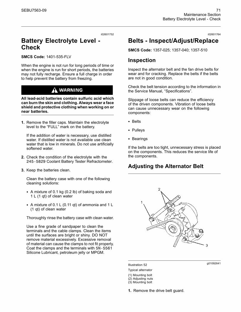
g01092641Illustration 52Typical alternator(1) Mounting bolt(2) Adjusting nuts(3) Mounting bolt
1. Remove the drive belt guard.
72 SEBU7563-09Maintenance SectionCombustion Sensor - Clean/Inspect/Replace
2. Loosen mounting bolt (1), adjusting nuts (2) andmounting bolt (3).
3. Turn adjusting nuts (2) in order to increase ordecrease the drive belt tension.
4. Tighten adjusting nuts (2). Tighten mounting bolt(3). Tighten mounting bolt (1). For the propertorque, see the Service Manual, “Specifications”module.
5. Reinstall the drive belt guard.
If new drive belts are installed, check the drive belttension again after 30 minutes of engine operation atthe rated rpm.
Adjusting the Fan Drive BeltNote: Do not overtighten the drive belts.Overtightening can result in failure of the drive shaft.
ReplacementFor applications that require multiple drive belts,replace the drive belts in matched sets. Replacingone drive belt of a matched set will cause the newdrive belt to carry more load because the older drivebelts are stretched. The additional load on the newdrive belt could cause the new drive belt to fail.
i02601781
Combustion Sensor -Clean/Inspect/ReplaceSMCS Code: 1900; 1905
To provide a signal without interference to the enginecontrol module, the sensor must be in good condition.The connections must be clean.
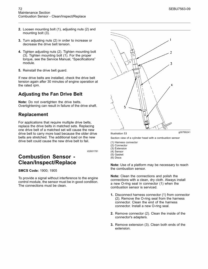
g00789241Illustration 53
Section view of a cylinder head with a combustion sensor
(1) Harness connector(2) Connector(3) Extension(4) Sensor(5) Gasket(6) Discs
Note: Use of a platform may be necessary to reachthe combustion sensor.
Note: Clean the connections and polish theconnections with a clean, dry cloth. Always installa new O-ring seal in connector (1) when thecombustion sensor is serviced.
1. Disconnect harness connector (1) from connector(2). Remove the O-ring seal from the harnessconnector. Clean the end of the harnessconnector. Install a new O-ring seal.
2. Remove connector (2). Clean the inside of theconnector's adapters.
3. Remove extension (3). Clean both ends of theextension.
SEBU7563-09 73Maintenance Section
Combustion Sensor - Clean/Inspect/Replace
Pressurized air can cause personal injury. Whenpressurized air is used for cleaning, wear a pro-tective face shield, protective clothing, and pro-tective shoes.
Note: The maximum air pressure for cleaningpurposes must be below 207 kPa (30 psi).
4. The area around sensor (4) may have debris.Thoroughly remove any debris. Use compressedair. Ensure that the area around the sensor isclean and free of debris.
5. Loosen sensor (4) with a 15.9 mm (5/8 inch) sparkplug socket and an extension. After the sensorhas been loosened, remove the sensor by hand inorder to detect problems with the threads.
If the sensor resists removal by hand, applypenetrating oil to the threads. Use the wrenchand apply steady pressure to the sensor until thesensor is loose.
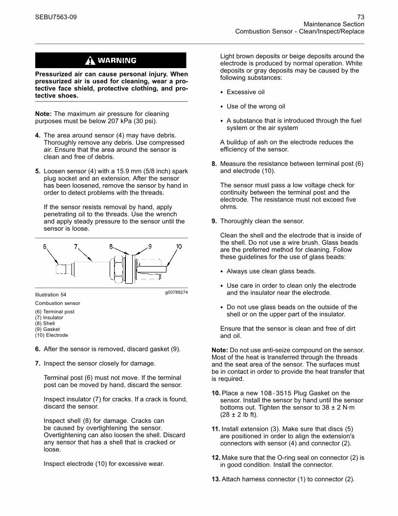
g00789274Illustration 54
Combustion sensor(6) Terminal post(7) Insulator(8) Shell(9) Gasket(10) Electrode
6. After the sensor is removed, discard gasket (9).
7. Inspect the sensor closely for damage.
Terminal post (6) must not move. If the terminalpost can be moved by hand, discard the sensor.
Inspect insulator (7) for cracks. If a crack is found,discard the sensor.
Inspect shell (8) for damage. Cracks canbe caused by overtightening the sensor.Overtightening can also loosen the shell. Discardany sensor that has a shell that is cracked orloose.
Inspect electrode (10) for excessive wear.
Light brown deposits or beige deposits around theelectrode is produced by normal operation. Whitedeposits or gray deposits may be caused by thefollowing substances:
• Excessive oil
• Use of the wrong oil
• A substance that is introduced through the fuelsystem or the air system
A buildup of ash on the electrode reduces theefficiency of the sensor.
8. Measure the resistance between terminal post (6)and electrode (10).
The sensor must pass a low voltage check forcontinuity between the terminal post and theelectrode. The resistance must not exceed fiveohms.
9. Thoroughly clean the sensor.
Clean the shell and the electrode that is inside ofthe shell. Do not use a wire brush. Glass beadsare the preferred method for cleaning. Followthese guidelines for the use of glass beads:
• Always use clean glass beads.
• Use care in order to clean only the electrodeand the insulator near the electrode.
• Do not use glass beads on the outside of theshell or on the upper part of the insulator.
Ensure that the sensor is clean and free of dirtand oil.
Note: Do not use anti-seize compound on the sensor.Most of the heat is transferred through the threadsand the seat area of the sensor. The surfaces mustbe in contact in order to provide the heat transfer thatis required.
10.Place a new 108-3515 Plug Gasket on thesensor. Install the sensor by hand until the sensorbottoms out. Tighten the sensor to 38 ± 2 N·m(28 ± 2 lb ft).
11. Install extension (3). Make sure that discs (5)are positioned in order to align the extension'sconnectors with sensor (4) and connector (2).
12.Make sure that the O-ring seal on connector (2) isin good condition. Install the connector.
13.Attach harness connector (1) to connector (2).

74 SEBU7563-09Maintenance SectionControl Panel - Inspect
i01762721
Control Panel - InspectSMCS Code: 4490-040; 7451-040
Inspect the condition of the panel. If a component isdamaged, ensure that the component is repaired orthat the component is replaced. If equipped, ensurethat the electronic displays are operating properly.
Inspect the wiring for good condition. Ensure that thewiring connections are secure.
Record the Data and Review theDataIf equipped, check the gauges and check theindicators frequently during normal operation. Recordthe data in a log. Compare the new data to the datathat was previously recorded. Comparing the newdata to the recorded data will establish the normalgauge readings for the engine. A gauge reading thatis abnormal may indicate a problem with operationor with the gauge.
i02601979
Cooling System Coolant(NGEC) - ChangeSMCS Code: 1350-044
Clean the cooling system before the recommendedmaintenance interval if the following conditions exist:
• The engine overheats frequently.
• Foaming is observed.
• The oil has entered the cooling system and thecoolant is contaminated.
NOTICEUse of commercially available cooling system clean-ers may cause damage to cooling system compo-nents. Use only cooling system cleaners that are ap-proved for Caterpillar engines.
Drain the Cooling System1. Stop the engine and allow the engine to cool.Ensure that the engine will not start when thecooling system is drained.
2. Loosen the cooling system filler cap slowly inorder to relieve any pressure. Remove the coolingsystem filler cap.
g00792409Illustration 55Location of cooling system drain valves or drain plugs on the waterpumps(1) Jacket water pump(2) Aftercooler and oil cooler pump
g00901833Illustration 56
Location of drain plug for the jacket water system
3. Open the cooling system drain valves (ifequipped). Remove the cooling system drainplugs. Allow the coolant to drain.
NOTICEDispose of used engine coolant properly or recycle.Various methods have been proposed to reclaim usedcoolant for reuse in engine cooling systems. The fulldistillation procedure is the only method acceptable byCaterpillar to reclaim the used coolant.
For information regarding the disposal and therecycling of used coolant, consult your Caterpillardealer or consult Caterpillar Dealer Service ToolsGroup:
Outside Illinois: 1-800-542-TOOLInside Illinois: 1-800-541-TOOLCanada: 1-800-523-TOOL

SEBU7563-09 75Maintenance Section
Cooling System Coolant (NGEC) - Change
Clean the Cooling System1. Flush the cooling system with clean water in orderto remove any debris.
2. Close the cooling system drain valves (ifequipped). Clean the cooling system drain plugsand install the cooling system drain plugs.
NOTICEFill the cooling system no faster than 19 L (5 US gal)per minute in order to avoid air locks. Proper ventingof the cooling system is essential to fill at this rate.
3. Fill the cooling system with a mixture of cleanwater and Caterpillar Fast Acting Cooling SystemCleaner. Add .5 L (1 pint) of cleaner per 15 L(4 US gal) of the cooling system capacity. Installthe cooling system filler cap.
4. Start the engine. Operate the engine for aminimum of 30 minutes with a coolant temperatureof at least 82 °C (180 °F).
5. Stop the engine and allow the engine to cool.Loosen the cooling system filler cap slowly inorder to relieve any pressure. Remove the coolingsystem filler cap. Open the cooling system drainvalves (if equipped). Remove the cooling systemdrain plugs. Allow the water to drain.
NOTICEImproper or incomplete rinsing of the cooling systemcan result in damage to copper and other metal com-ponents.
To avoid damage to the cooling system, make sureto completely flush the cooling system with clear wa-ter. Continue to flush the system until all signs of thecleaning agent are gone.
6. Flush the cooling system with clean water untilthe water that drains is clean. Close the coolingsystem drain valves (if equipped). Clean thecooling system drain plugs and install the coolingsystem drain plugs.
Cleaning a Cooling System thathas Heavy Deposits or PluggingNote: For the following procedure to be effective,there must be an active flow through the coolingsystem components.
1. Flush the cooling system with clean water in orderto remove any debris.
2. Close the cooling system drain valves (ifequipped). Clean the cooling system drain plugsand install the cooling system drain plugs.
3. Fill the cooling system with a mixture of cleanwater and Caterpillar Fast Acting Cooling SystemCleaner. Add .5 L (1 pint) of cleaner per 3.8 to 7.6 L(1 to 2 US gal) of the cooling system capacity.Install the cooling system filler cap.
4. Start the engine. Operate the engine for aminimum of 90 minutes with a coolant temperatureof at least 82 °C (180 °F).
5. Stop the engine and allow the engine to cool.Loosen the cooling system filler cap slowly inorder to relieve any pressure. Remove the coolingsystem filler cap. Open the cooling system drainvalves (if equipped). Remove the cooling systemdrain plugs. Allow the water to drain.
NOTICEImproper or incomplete rinsing of the cooling systemcan result in damage to copper and other metal com-ponents.
To avoid damage to the cooling system, make sureto completely flush the cooling system with clear wa-ter. Continue to flush the system until all signs of thecleaning agent are gone.
6. Flush the cooling system with clean water untilthe water that drains is clean. Close the coolingsystem drain valves (if equipped). Clean thecooling system drain plugs and install the coolingsystem drain plugs.
Fill the Cooling System
NOTICEFill the cooling system no faster than 19 L (5 US gal)per minute in order to avoid air locks. Proper ventingof the cooling system is essential to fill at this rate.
Note: For information about the proper coolant touse, and the capacity of the cooling system, seethis Operation and Maintenance Manual, “RefillCapacities and Recommendations” (MaintenanceSection).
1. Fill the cooling system with coolant/antifreeze. Donot install the cooling system filler cap.
2. Start the engine. Operate the engine in order topurge the air from the cavities of the engine block.Allow the coolant to warm and allow the coolantlevel to stabilize. Stop the engine.
76 SEBU7563-09Maintenance SectionCooling System Coolant Level - Check
3. Check the coolant level. Maintain the coolant tothe proper level on the sight gauge (if equipped).If a sight gauge is not equipped, maintain thecoolant to the level that is specified by the OEMof the cooling system.
4. Clean the cooling system filler cap. Inspectthe gaskets of the cooling system filler cap. Ifthe gaskets of the cooling system filler cap aredamaged, discard the old cooling system filler capand install a new cooling system filler cap. If thegaskets of the cooling system filler cap are notdamaged, use a 9S-8140 Pressurizing Pump inorder to pressure test the cooling system filler cap.The correct pressure is stamped on the face ofthe cooling system filler cap. If the cooling systemfiller cap does not retain the correct pressure,install a new cooling system filler cap.
5. Start the engine. Inspect the cooling system forleaks and for proper operating temperature.
i02062976
Cooling System Coolant Level- CheckSMCS Code: 1350-535-FLV
Climbing equipment may be required to accessthis service point. Refer to the Operation andMaintenance Manual, “Mounting and Dismount-ing” topic for safety information.
Engines That Are Equipped With aSight Gauge
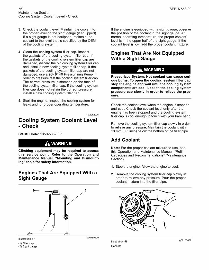
g00750429Illustration 57(1) Filler cap(2) Sight gauge
If the engine is equipped with a sight gauge, observethe position of the coolant in the sight gauge. Atnormal operating temperature, the proper coolantlevel is in the upper half of the sight gauge. If thecoolant level is low, add the proper coolant mixture.
Engines That Are Not EquippedWith a Sight Gauge
Pressurized System: Hot coolant can cause seri-ous burns. To open the cooling system filler cap,stop the engine and wait until the cooling systemcomponents are cool. Loosen the cooling systempressure cap slowly in order to relieve the pres-sure.
Check the coolant level when the engine is stoppedand cool. Check the coolant level only after theengine has been stopped and the cooling systemfiller cap is cool enough to touch with your bare hand.
Remove the cooling system filler cap slowly in orderto relieve any pressure. Maintain the coolant within13 mm (0.5 inch) below the bottom of the filler pipe.
Add CoolantNote: For the proper coolant mixture to use, seethis Operation and Maintenance Manual, “RefillCapacities and Recommendations” (MaintenanceSection).
1. Stop the engine. Allow the engine to cool.
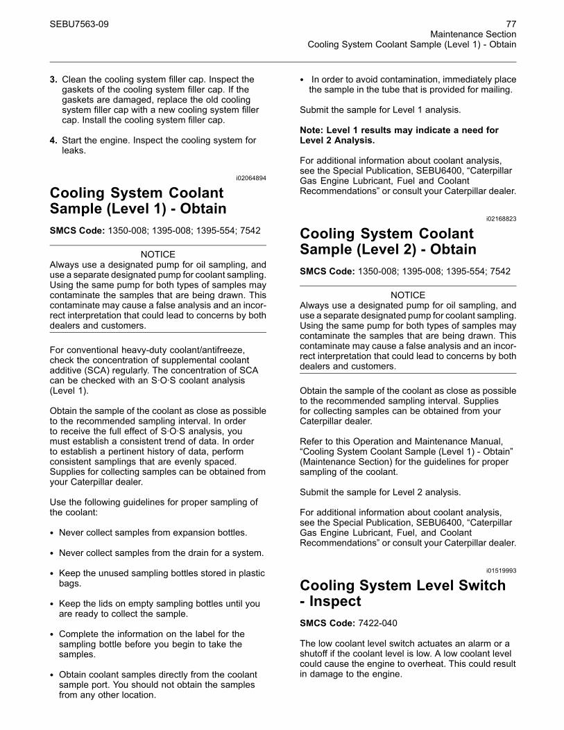
2. Remove the cooling system filler cap slowly inorder to relieve any pressure. Pour the propercoolant mixture into the filler pipe.
g00103639Illustration 58
Gaskets
SEBU7563-09 77Maintenance Section
Cooling System Coolant Sample (Level 1) - Obtain
3. Clean the cooling system filler cap. Inspect thegaskets of the cooling system filler cap. If thegaskets are damaged, replace the old coolingsystem filler cap with a new cooling system fillercap. Install the cooling system filler cap.
4. Start the engine. Inspect the cooling system forleaks.
i02064894
Cooling System CoolantSample (Level 1) - ObtainSMCS Code: 1350-008; 1395-008; 1395-554; 7542
NOTICEAlways use a designated pump for oil sampling, anduse a separate designated pump for coolant sampling.Using the same pump for both types of samples maycontaminate the samples that are being drawn. Thiscontaminate may cause a false analysis and an incor-rect interpretation that could lead to concerns by bothdealers and customers.
For conventional heavy-duty coolant/antifreeze,check the concentration of supplemental coolantadditive (SCA) regularly. The concentration of SCAcan be checked with an S·O·S coolant analysis(Level 1).
Obtain the sample of the coolant as close as possibleto the recommended sampling interval. In orderto receive the full effect of S·O·S analysis, youmust establish a consistent trend of data. In orderto establish a pertinent history of data, performconsistent samplings that are evenly spaced.Supplies for collecting samples can be obtained fromyour Caterpillar dealer.
Use the following guidelines for proper sampling ofthe coolant:
• Never collect samples from expansion bottles.
• Never collect samples from the drain for a system.
• Keep the unused sampling bottles stored in plasticbags.
• Keep the lids on empty sampling bottles until youare ready to collect the sample.
• Complete the information on the label for thesampling bottle before you begin to take thesamples.
• Obtain coolant samples directly from the coolantsample port. You should not obtain the samplesfrom any other location.
• In order to avoid contamination, immediately placethe sample in the tube that is provided for mailing.
Submit the sample for Level 1 analysis.
Note: Level 1 results may indicate a need forLevel 2 Analysis.
For additional information about coolant analysis,see the Special Publication, SEBU6400, “CaterpillarGas Engine Lubricant, Fuel and CoolantRecommendations” or consult your Caterpillar dealer.
i02168823
Cooling System CoolantSample (Level 2) - ObtainSMCS Code: 1350-008; 1395-008; 1395-554; 7542
NOTICEAlways use a designated pump for oil sampling, anduse a separate designated pump for coolant sampling.Using the same pump for both types of samples maycontaminate the samples that are being drawn. Thiscontaminate may cause a false analysis and an incor-rect interpretation that could lead to concerns by bothdealers and customers.
Obtain the sample of the coolant as close as possibleto the recommended sampling interval. Suppliesfor collecting samples can be obtained from yourCaterpillar dealer.
Refer to this Operation and Maintenance Manual,“Cooling System Coolant Sample (Level 1) - Obtain”(Maintenance Section) for the guidelines for propersampling of the coolant.
Submit the sample for Level 2 analysis.
For additional information about coolant analysis,see the Special Publication, SEBU6400, “CaterpillarGas Engine Lubricant, Fuel, and CoolantRecommendations” or consult your Caterpillar dealer.
i01519993
Cooling System Level Switch- InspectSMCS Code: 7422-040
The low coolant level switch actuates an alarm or ashutoff if the coolant level is low. A low coolant levelcould cause the engine to overheat. This could resultin damage to the engine.
78 SEBU7563-09Maintenance SectionCooling System Supplemental Coolant Additive (SCA) - Test/Add
If the coolant level is low, coolant must be added tothe expansion tank or the heat exchanger.
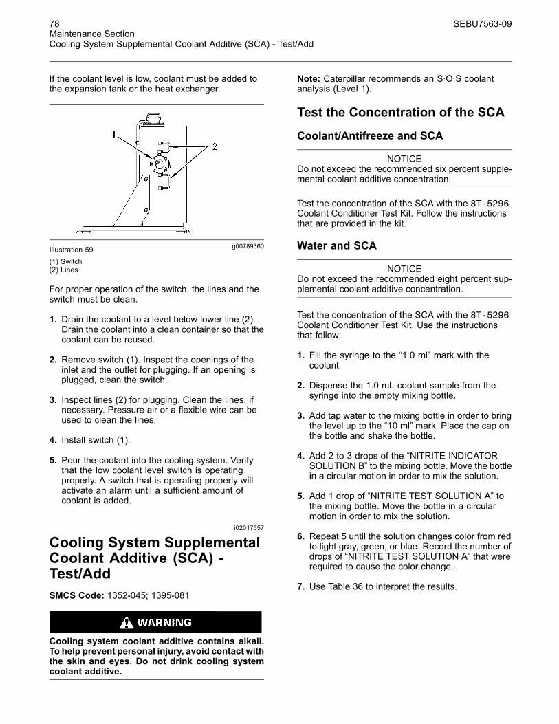
g00789360Illustration 59(1) Switch(2) Lines
For proper operation of the switch, the lines and theswitch must be clean.
1. Drain the coolant to a level below lower line (2).Drain the coolant into a clean container so that thecoolant can be reused.
2. Remove switch (1). Inspect the openings of theinlet and the outlet for plugging. If an opening isplugged, clean the switch.
3. Inspect lines (2) for plugging. Clean the lines, ifnecessary. Pressure air or a flexible wire can beused to clean the lines.
4. Install switch (1).
5. Pour the coolant into the cooling system. Verifythat the low coolant level switch is operatingproperly. A switch that is operating properly willactivate an alarm until a sufficient amount ofcoolant is added.
i02017557
Cooling System SupplementalCoolant Additive (SCA) -Test/AddSMCS Code: 1352-045; 1395-081
Cooling system coolant additive contains alkali.To help prevent personal injury, avoid contact withthe skin and eyes. Do not drink cooling systemcoolant additive.
Note: Caterpillar recommends an S·O·S coolantanalysis (Level 1).
Test the Concentration of the SCA
Coolant/Antifreeze and SCA
NOTICEDo not exceed the recommended six percent supple-mental coolant additive concentration.
Test the concentration of the SCA with the 8T-5296Coolant Conditioner Test Kit. Follow the instructionsthat are provided in the kit.
Water and SCA
NOTICEDo not exceed the recommended eight percent sup-plemental coolant additive concentration.
Test the concentration of the SCA with the 8T-5296Coolant Conditioner Test Kit. Use the instructionsthat follow:
1. Fill the syringe to the “1.0 ml” mark with thecoolant.
2. Dispense the 1.0 mL coolant sample from thesyringe into the empty mixing bottle.
3. Add tap water to the mixing bottle in order to bringthe level up to the “10 ml” mark. Place the cap onthe bottle and shake the bottle.
4. Add 2 to 3 drops of the “NITRITE INDICATORSOLUTION B” to the mixing bottle. Move the bottlein a circular motion in order to mix the solution.
5. Add 1 drop of “NITRITE TEST SOLUTION A” tothe mixing bottle. Move the bottle in a circularmotion in order to mix the solution.
6. Repeat 5 until the solution changes color from redto light gray, green, or blue. Record the number ofdrops of “NITRITE TEST SOLUTION A” that wererequired to cause the color change.
7. Use Table 36 to interpret the results.

SEBU7563-09 79Maintenance Section
Cooling System Water Temperature Regulator - Replace
Table 36
Number ofDrops
Concentrationof SCA
MaintenanceRequired
Less than 25 Less than therecommendedconcentration ofSCA
Add SCA.Retest thecoolant.
25 to 30 Therecommendedconcentration ofSCA
None
More than 30 More than therecommendedconcentration ofSCA
Remove thecoolant.Replace withwater onlyRetest thecoolant.
Add the SCA, If Necessary
Pressurized System: Hot coolant can cause seri-ous burns. To open the cooling system filler cap,stop the engine and wait until the cooling systemcomponents are cool. Loosen the cooling systempressure cap slowly in order to relieve the pres-sure.
1. Remove the cooling system filler cap slowly.
Note: Always dispose of fluids according to localregulations.
2. If necessary, drain some coolant in order to allowspace for the addition of the SCA.
NOTICEExcessive supplemental coolant additive concentra-tion can form deposits on the higher temperature sur-faces of the cooling system, reducing the engine'sheat transfer characteristics. Reduced heat transfercould cause cracking of the cylinder head and otherhigh temperature components.
Excessive supplemental coolant additive concentra-tion could also result in blockage of the heat exchang-er, overheating, and/or accelerated wear of the waterpump seal.
Do not exceed the recommended amount of supple-mental coolant additive concentration.
3. Add the proper amount of SCA. The concentrationof the SCA depends on the type of coolant thatis used. To determine the proper amount, seethis Operation and Maintenance Manual, “RefillCapacities and Recommendations” topic.
4. Clean the cooling system filler cap. Install thecooling system filler cap.
i02168842
Cooling System WaterTemperature Regulator -ReplaceSMCS Code: 1355-510
Replace the water temperature regulators for thesesystems:
• Jacket water
• Oil cooler
• Aftercooler
Replace the water temperature regulators beforethe water temperature regulators fail. This is arecommended preventive maintenance practice.Replacing the water temperature regulators reducesthe chances for unscheduled downtime.
A water temperature regulator that fails in apartially opened position can cause overheating orovercooling of the engine.
A water temperature regulator that fails in the closedposition can cause excessive overheating. Excessiveoverheating could result in cracking of the cylinderhead or a seizure of the pistons.
A water temperature regulator that fails in the openposition will cause the engine operating temperatureto be too low during partial load operation. Lowengine operating temperatures during partial loadscould cause an excessive carbon buildup inside thecylinders. This excessive carbon buildup could resultin an accelerated wear of the piston rings and wearof the cylinder liner. Also, a low temperature canallow moisture to condense in the oil. This can formdamaging acids.
NOTICEFailure to replace the water temperature regulator ona regularly scheduled basis could cause severe en-gine damage.
Never operate an engine without the water tempera-ture regulator installed.
If the water temperature regulator is installed incor-rectly, the enginemay overheat, causing cylinder headdamage. Ensure that the new water temperature reg-ulator is installed in the original position.
80 SEBU7563-09Maintenance SectionCrankcase Blowby - Measure/Record
Note: If only the water temperature regulators arereplaced, drain the coolant from the cooling system toa level that is below the water temperature regulatorhousing.
i02602965
Crankcase Blowby -Measure/RecordSMCS Code: 1317
Note: The typical crankcase blowby on a new engineis approximately 0.02 m3/bkW h (.50 ft3/bhp h).
Measure the crankcase blowby of new engines.Record the data. Continue to periodically measurethe crankcase blowby. Comparing the recordeddata to the new data provides information about thecondition of the engine.
Note: Crankcase blowby is one of the three factorsthat help to determine the in-frame overhaul interval.For more information, see the Operation andMaintenance manual, “Overhaul (In-Frame)” topic inthe Maintenance Section.
After a new engine is used for a short time, thecrankcase blowby can decrease as the piston ringsare seated. The crankcase blowby will graduallyincrease as the following components show wear:
• piston rings
• cylinder liners
Note: A problem with the piston rings causes theoil to deteriorate rapidly. Information regarding thecondition of the piston rings can be obtained fromthe measurement of the crankcase blowby and theresults of oil analysis.
The crankcase blowby of a worn engine may exceedthe crankcase blowby of a new engine by two timesor more.
A sudden increase in crankcase blowby couldindicate a broken piston ring. The following conditionsare other potential sources of crankcase blowby:
• Worn valve guides
• A turbocharger seal that leaks
A rebuilt engine can have a high crankcase blowbydue to the following factors:
• The piston rings are not seated properly.
• Worn parts such as valve guides were not replaced.
Excessive crankcase blowby may indicate the needfor an overhaul. By keeping a record of the results,a gradual increase in the amount of the crankcaseblowby will be noted until the amount of crankcaseblowby has become excessive.
Use the 1U-8860 Large Engine Blowby PickupGroup to measure the blowby. Refer to SpecialInstruction, SEHS8984, “1U-8860 Large EngineBlowby Pickup Group” that is provided with the tool.
Record the crankcase blowby for the engine. Keep arecord of the results.
For more information, see the Service Manual,“Systems Operation/Testing and Adjusting”. Forassistance, consult your Caterpillar dealer.
i02062446
Crankshaft Vibration Damper- InspectSMCS Code: 1205-040
The crankshaft vibration damper limits the torsionalvibration of the crankshaft. The visconic damper hasa weight that is located inside a fluid filled case.
Damage to the crankshaft vibration damper or failureof the damper can increase torsional vibrations. Thiscan result in damage to the crankshaft and to otherengine components. A deteriorating damper cancause excessive gear train noise at variable pointsin the speed range.
A damper that is hot is due to excessive torsionalvibration. Monitor the temperature of the damperduring operation.
The 8T-2821 Temperature Indicator or the 8T-2822Temperature Indicator are recommended formonitoring the temperature of the damper. Evenlyspace four of the adhesive indicators around theouter diameter of the damper.
Note: If you use an infrared thermometer to monitorthe temperature of the damper, use the thermometerduring operation with similar loads and speeds. Keepa record of the data. If the temperature begins to rise,reduce the interval for inspecting the damper. It isimportant to regularly monitor the temperature of thedamper. It is important to document the temperatureof the damper when it increases and decreases. Thiswill verify that damper service is necessary.
If the temperature of the damper reaches 110 °C(230 °F), consult your Caterpillar dealer.
Inspect the damper for evidence of dents, cracks,and leaks of the fluid.
SEBU7563-09 81Maintenance Section
Cylinder Pressure - Measure/Record
If a fluid leak is found, determine the type of fluid.The fluid in the damper is silicone. Silicone hasthe following characteristics: transparent, viscous,smooth, and sticky. If leaking silicone is found, repairthe damper or replace the damper.
If the fluid leak is oil, inspect the crankshaft seal forleaks. If a leak is observed, replace the seal.
Inspect the damper and repair or replace the damperfor any of the following reasons.
• The damper is dented, cracked, or leaking.
• The paint on the damper is discolored from heat.
• The engine has had a failure because of a brokencrankshaft.
• An analysis of the oil has revealed that the frontbearing of the crankshaft is badly worn.
• There is a large amount of gear train wear that isnot caused by a lack of oil.
Removal and InstallationRefer to the Service Manual, “Disassembly andAssembly” or consult your Caterpillar dealer forinformation about damper replacement.
i02602007
Cylinder Pressure -Measure/RecordSMCS Code: 1223-082-CC; 1223; 7450-082
Measure the cylinder pressure of new engines.Record the data. Continue to periodically measurethe cylinder pressure. Comparing the recorded datato the new data provides information about thecondition of the engine.
Note: Cylinder pressure is one of the three factorsthat help to determine the in-frame overhaul interval.For more information, refer to this Operationand Maintenance manual, “Overhaul (In-Frame)”(Maintenance Section).
Cylinder pressure can be measured during inspectionof the spark plugs. Use the following guidelines forchecking the cylinder pressure:
• Remove all of the spark plugs.
• Verify that the choke is fully open.
• Minimize the cranking time. This will enable amaximum consistent cranking speed for the check.Also, the starting air or battery power will beconserved.
A loss of cylinder pressure or a change of pressurein one or more cylinders may indicate the followingconditions. These conditions may indicate a problemwith lubrication:
• Excessive deposits
• Guttering of valves
• A broken valve
• A piston ring that sticks
• A broken piston ring
• Worn piston rings
• Worn cylinder liners
If the cylinder pressure has risen by one or morecompression ratios, the engine needs a top endoverhaul in order to remove deposits. Failure toremove the deposits will increase the chance fordetonation. Severe guttering of the valves will occur.
To measure the cylinder pressure, refer to SpecialInstruction, GMG00694, “Analyzing CylinderCondition By Measuring Air Flow”. Also, use the146-2739 Cylinder Pressure Adapter.
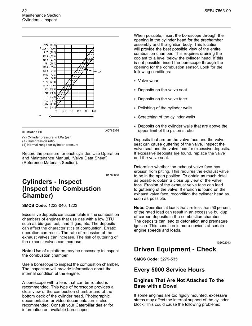
Illustration 60 is a graph of typical cylinder pressuresfor engines with different compression ratios.
82 SEBU7563-09Maintenance SectionCylinders - Inspect
g00789376Illustration 60(Y) Cylinder pressure in kPa (psi)(X) Compression ratio(1) Normal range for cylinder pressure
Record the pressure for each cylinder. Use Operationand Maintenance Manual, “Valve Data Sheet”(Reference Materials Section).
i01765658
Cylinders - Inspect(Inspect the CombustionChamber)SMCS Code: 1223-040; 1223
Excessive deposits can accumulate in the combustionchambers of engines that use gas with a low BTUsuch as bio-gas fuel, landfill gas, etc. The depositscan affect the characteristics of combustion. Erraticoperation can result. The rate of recession of theexhaust valves can increase. The risk of guttering ofthe exhaust valves can increase.
Note: Use of a platform may be necessary to inspectthe combustion chamber.
Use a borescope to inspect the combustion chamber.The inspection will provide information about theinternal condition of the engine.
A borescope with a lens that can be rotated isrecommended. This type of borescope provides aclear view of the combustion chamber and of thebottom deck of the cylinder head. Photographicdocumentation or video documentation is alsorecommended. Consult your Caterpillar dealer forinformation on available borescopes.
When possible, insert the borescope through theopening in the cylinder head for the prechamberassembly and the ignition body. This locationwill provide the best possible view of the entirecombustion chamber. This requires draining thecoolant to a level below the cylinder head. If thisis not possible, insert the borescope through theopening for the combustion sensor. Look for thefollowing conditions:
• Valve wear
• Deposits on the valve seat
• Deposits on the valve face
• Polishing of the cylinder walls
• Scratching of the cylinder walls
• Deposits on the cylinder walls that are above theupper limit of the piston stroke
Deposits that are on the valve face and the valveseat can cause guttering of the valve. Inspect thevalve seat and the valve face for excessive deposits.If excessive deposits are found, replace the valveand the valve seat.
Determine whether the exhaust valve face haserosion from pitting. This requires the exhaust valveto be in the open position. To obtain as much detailas possible, obtain a close up view of the valveface. Erosion of the exhaust valve face can leadto guttering of the valve. If erosion is found on theexhaust valve face, recondition the cylinder head assoon as possible.
Note: Operation at loads that are less than 50 percentof the rated load can result in an excessive buildupof carbon deposits in the combustion chamber.The deposits can lead to detonation and prematureignition. This condition is more obvious at certainengine speeds and loads.
i02602013
Driven Equipment - CheckSMCS Code: 3279-535
Every 5000 Service Hours
Engines That Are Not Attached To theBase with a Dowel
If some engines are too rigidly mounted, excessivestress may affect the internal support of the cylinderblock. This could cause the following problems:
SEBU7563-09 83Maintenance Section
Driven Equipment - Inspect/Replace/Lubricate
• Distortion of the bores of the main bearing
• Distortion of the alignment of the bore
Severe damage to the engine could result. Theservice life of the engine could be severely reduced.
For engines that are not attached to the base with adowel, check the following:
• Check the alignment after every 5000 servicehours.
• Inspect the drive coupling according to thespecifications of the OEM.
Every 10,000 Service Hours
Engines That Are Attached To the Basewith a Dowel
Some engines must be more rigidly mounted. Due tothermal expansion, a cold engine will expand afterthe engine achieves operating temperature.
Some engines are attached to the base with a dowelin the rear mounting support. This installation forcesthe thermal growth forward. The driven equipmentis also attached with a dowel in order to maintainalignment with the engine.
For this type of installation, check the alignment afterevery 10,000 service hours.
Check the AlignmentThe alignment between the engine and the drivenequipment must be maintained properly. Improperalignment will cause damage to the engine, thecoupling, and the driven equipment.
Check the alignment according to the instructionsthat are provided by the following manufacturers:
• Caterpillar
• OEM of the coupling
• OEM of the driven equipment
i00935098
Driven Equipment -Inspect/Replace/LubricateSMCS Code: 3279-040
Observe the driven equipment during operation. Lookfor the following items:
• Unusual noise and vibration
• Loose connections
• Damaged parts
Perform any maintenance that is recommendedby the OEM of the driven equipment. Refer to theliterature of the OEM of the driven equipment for thefollowing service instructions.
• Inspection
• Lubricating grease and lubricating oil requirements
• Specifications for adjustment
• Replacement of components
• Requirements for ventilation
i01610487
Electrohydraulic Actuator -InspectSMCS Code: 1716-040
Inspect the actuators for the fuel control, thewastegate, and the air choke.
During operation, the linkage of the electrohy-draulic actuators can form pinch points whichcan cause personal injury. Shut down the enginebefore you service the electrohydraulic actuators.
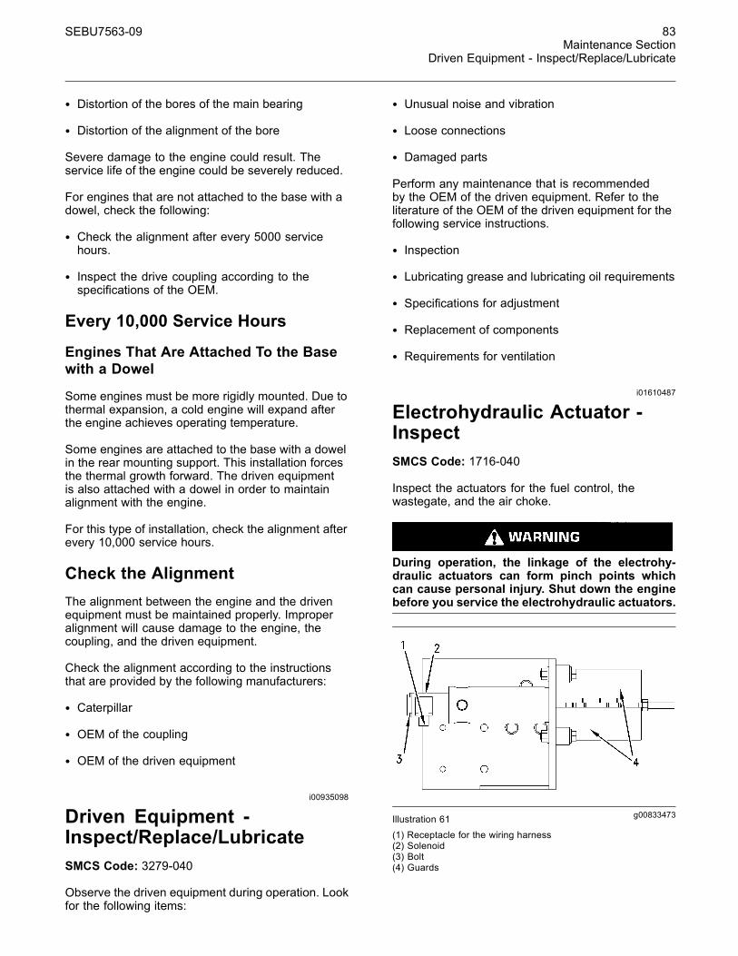
g00833473Illustration 61
(1) Receptacle for the wiring harness(2) Solenoid(3) Bolt(4) Guards
84 SEBU7563-09Maintenance SectionElectrohydraulic Actuator - Recondition
1. Disconnect the wiring harness from receptacle (1).Inspect the connectors for damage and corrosion.Make repairs, if necessary.
2. Inspect the joint between solenoid (2) and thehousing for leaks.
If a leak is found between the solenoid and thehousing, replace the O-ring seal for the solenoid.For instructions, refer to this Operation andMaintenance Manual, “Electrohydraulic Actuator -Recondition”.
3. Check the solenoid's mounting bolts (3) fortightness.
4. Remove guards (4).
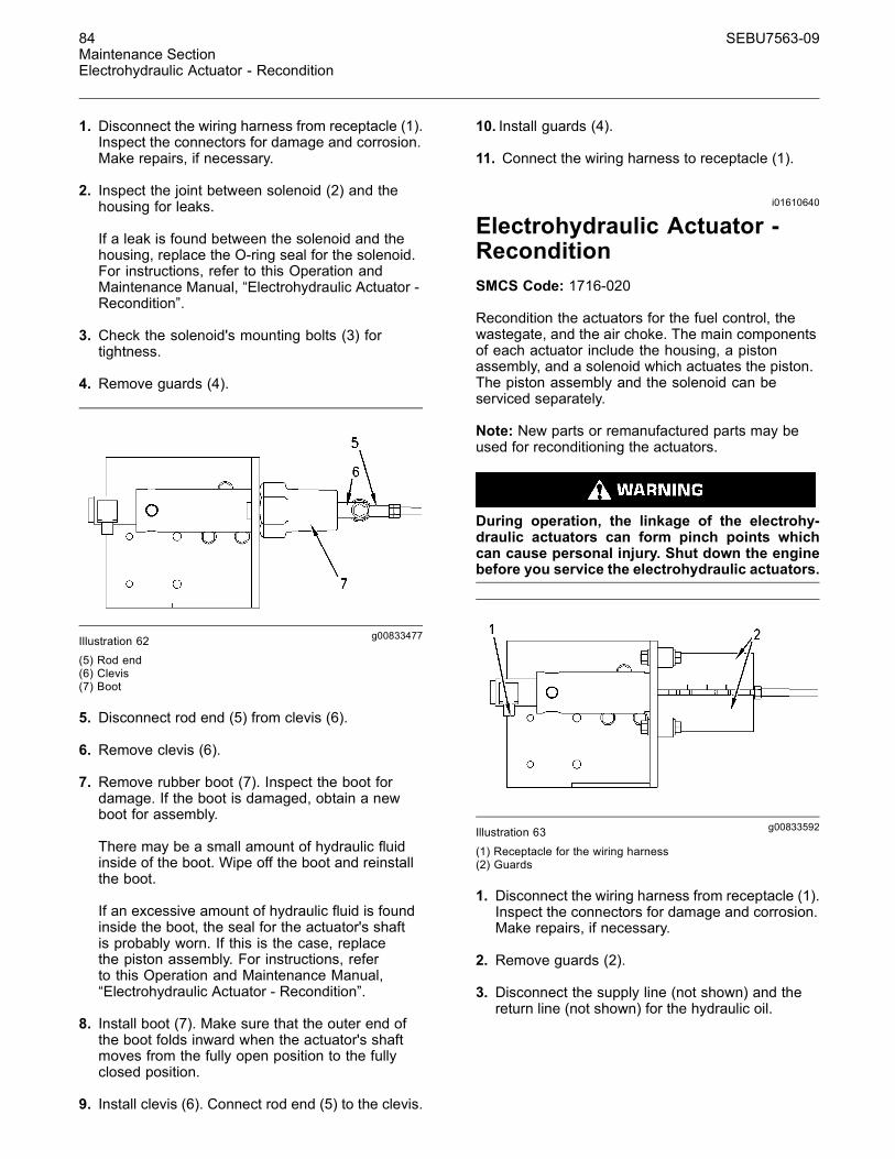
g00833477Illustration 62(5) Rod end(6) Clevis(7) Boot
5. Disconnect rod end (5) from clevis (6).
6. Remove clevis (6).
7. Remove rubber boot (7). Inspect the boot fordamage. If the boot is damaged, obtain a newboot for assembly.
There may be a small amount of hydraulic fluidinside of the boot. Wipe off the boot and reinstallthe boot.
If an excessive amount of hydraulic fluid is foundinside the boot, the seal for the actuator's shaftis probably worn. If this is the case, replacethe piston assembly. For instructions, referto this Operation and Maintenance Manual,“Electrohydraulic Actuator - Recondition”.
8. Install boot (7). Make sure that the outer end ofthe boot folds inward when the actuator's shaftmoves from the fully open position to the fullyclosed position.
9. Install clevis (6). Connect rod end (5) to the clevis.
10. Install guards (4).
11. Connect the wiring harness to receptacle (1).
i01610640
Electrohydraulic Actuator -ReconditionSMCS Code: 1716-020
Recondition the actuators for the fuel control, thewastegate, and the air choke. The main componentsof each actuator include the housing, a pistonassembly, and a solenoid which actuates the piston.The piston assembly and the solenoid can beserviced separately.
Note: New parts or remanufactured parts may beused for reconditioning the actuators.
During operation, the linkage of the electrohy-draulic actuators can form pinch points whichcan cause personal injury. Shut down the enginebefore you service the electrohydraulic actuators.
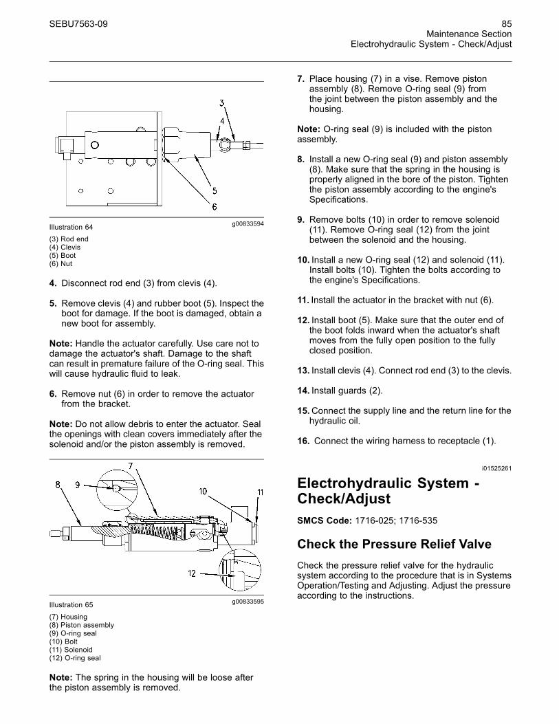
g00833592Illustration 63
(1) Receptacle for the wiring harness(2) Guards
1. Disconnect the wiring harness from receptacle (1).Inspect the connectors for damage and corrosion.Make repairs, if necessary.
2. Remove guards (2).
3. Disconnect the supply line (not shown) and thereturn line (not shown) for the hydraulic oil.
SEBU7563-09 85Maintenance Section
Electrohydraulic System - Check/Adjust
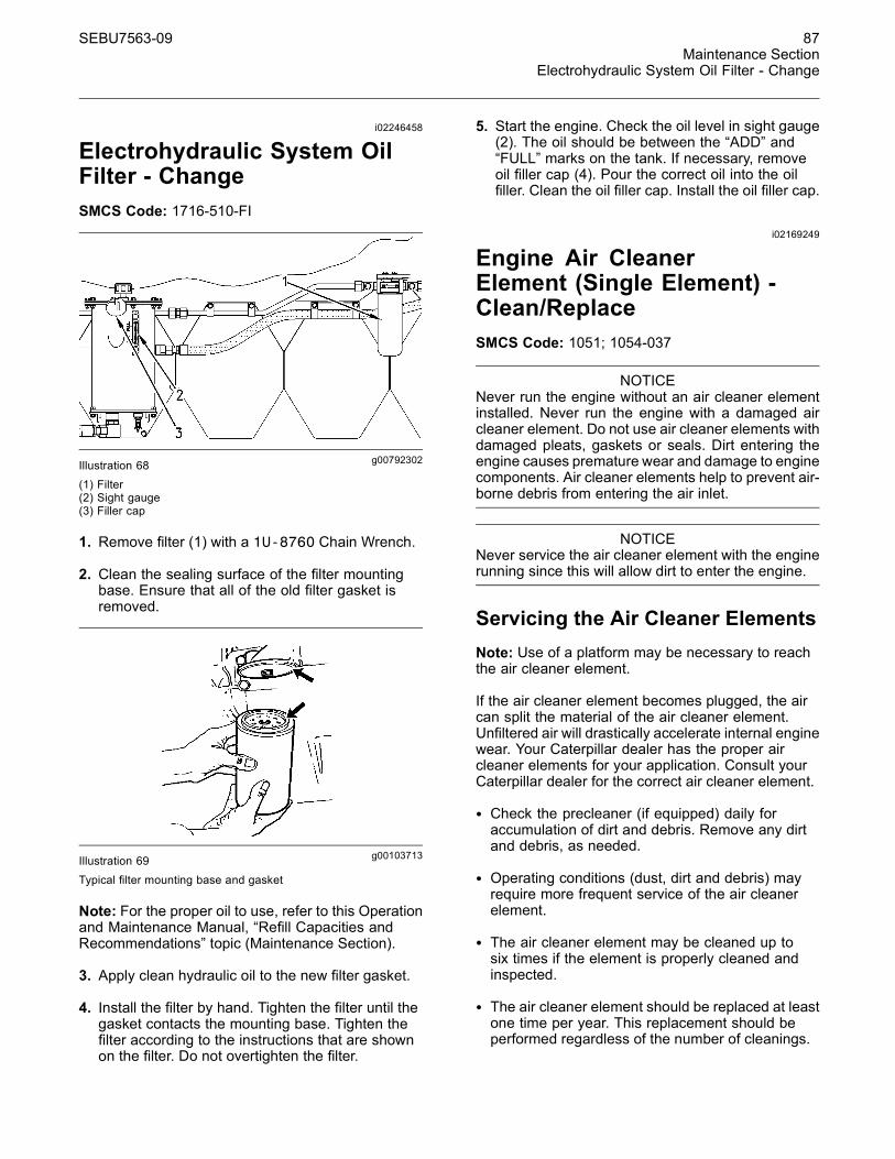
g00833594Illustration 64(3) Rod end(4) Clevis(5) Boot(6) Nut
4. Disconnect rod end (3) from clevis (4).
5. Remove clevis (4) and rubber boot (5). Inspect theboot for damage. If the boot is damaged, obtain anew boot for assembly.
Note: Handle the actuator carefully. Use care not todamage the actuator's shaft. Damage to the shaftcan result in premature failure of the O-ring seal. Thiswill cause hydraulic fluid to leak.
6. Remove nut (6) in order to remove the actuatorfrom the bracket.
Note: Do not allow debris to enter the actuator. Sealthe openings with clean covers immediately after thesolenoid and/or the piston assembly is removed.
g00833595Illustration 65
(7) Housing(8) Piston assembly(9) O-ring seal(10) Bolt(11) Solenoid(12) O-ring seal
Note: The spring in the housing will be loose afterthe piston assembly is removed.
7. Place housing (7) in a vise. Remove pistonassembly (8). Remove O-ring seal (9) fromthe joint between the piston assembly and thehousing.
Note: O-ring seal (9) is included with the pistonassembly.
8. Install a new O-ring seal (9) and piston assembly(8). Make sure that the spring in the housing isproperly aligned in the bore of the piston. Tightenthe piston assembly according to the engine'sSpecifications.
9. Remove bolts (10) in order to remove solenoid(11). Remove O-ring seal (12) from the jointbetween the solenoid and the housing.
10. Install a new O-ring seal (12) and solenoid (11).Install bolts (10). Tighten the bolts according tothe engine's Specifications.
11. Install the actuator in the bracket with nut (6).
12. Install boot (5). Make sure that the outer end ofthe boot folds inward when the actuator's shaftmoves from the fully open position to the fullyclosed position.
13. Install clevis (4). Connect rod end (3) to the clevis.
14. Install guards (2).
15.Connect the supply line and the return line for thehydraulic oil.
16. Connect the wiring harness to receptacle (1).
i01525261
Electrohydraulic System -Check/AdjustSMCS Code: 1716-025; 1716-535
Check the Pressure Relief ValveCheck the pressure relief valve for the hydraulicsystem according to the procedure that is in SystemsOperation/Testing and Adjusting. Adjust the pressureaccording to the instructions.

86 SEBU7563-09Maintenance SectionElectrohydraulic System - Inspect
i02214104
Electrohydraulic System -InspectSMCS Code: 1716-040
Inspect the conditions of these items for theelectrohydraulic system:
• Oil level
• Hoses, lines, connections, and components
g00792283Illustration 66
(1) Sight gauge(2) Hose(3) Line
Check the Oil Level1. Check the oil level in sight gauge (1).
The oil should be between the “ADD” and “FULL”marks on the tank.
Note: For the proper oil to use, refer to this Operationand Maintenance Manual, “Refill Capacities andRecommendatons” topic (Maintenance Section).
2. If necessary, remove the oil filler cap. Pour thecorrect oil into the oil filler.
3. Clean the oil filler cap. Install the oil filler cap.
Inspect the Lines, Connections,and Components
The linkage can move and form a pinch pointwhich can cause personal injury. Keep handsaway from the linkage.
Inspect the hoses and lines for wear and leaks.Ensure that the hoses and lines are properlyclamped. Inspect the connections for leaks. Ensurethat the connections are secure.
Inspect the following items for leaks and goodcondition:
• Actuators
• Pressure relief valve
• Pump
Make repairs, if necessary.
i02603161
Electrohydraulic System Oil -ChangeSMCS Code: 1716-510-OC
Ensure that the engine cannot start during thisprocedure.
g00792335Illustration 67(1) Oil filler cap(2) Valve
1. Remove oil filler cap (1).
Note: Drain the oil into a suitable container. Disposeof fluids according to local regulations.
2. Place a suitable container under valve (2). Openthe valve. Allow the oil to drain. After the oil hasdrained, close the valve.
Note: For the proper oil to use, refer to the SpecialPublication, SEBU6400, “Caterpillar Gas EngineLubricant, Fuel and Coolant Recommendations” .
3. Pour the proper oil into the oil filler. Clean the oilfiller cap. Install the oil filler cap.
4. Clean up any oil that may have spilled.
SEBU7563-09 87Maintenance Section
Electrohydraulic System Oil Filter - Change
i02246458
Electrohydraulic System OilFilter - ChangeSMCS Code: 1716-510-FI
g00792302Illustration 68(1) Filter(2) Sight gauge(3) Filler cap
1. Remove filter (1) with a 1U-8760 Chain Wrench.
2. Clean the sealing surface of the filter mountingbase. Ensure that all of the old filter gasket isremoved.
g00103713Illustration 69Typical filter mounting base and gasket
Note: For the proper oil to use, refer to this Operationand Maintenance Manual, “Refill Capacities andRecommendations” topic (Maintenance Section).
3. Apply clean hydraulic oil to the new filter gasket.
4. Install the filter by hand. Tighten the filter until thegasket contacts the mounting base. Tighten thefilter according to the instructions that are shownon the filter. Do not overtighten the filter.
5. Start the engine. Check the oil level in sight gauge(2). The oil should be between the “ADD” and“FULL” marks on the tank. If necessary, removeoil filler cap (4). Pour the correct oil into the oilfiller. Clean the oil filler cap. Install the oil filler cap.
i02169249
Engine Air CleanerElement (Single Element) -Clean/ReplaceSMCS Code: 1051; 1054-037
NOTICENever run the engine without an air cleaner elementinstalled. Never run the engine with a damaged aircleaner element. Do not use air cleaner elements withdamaged pleats, gaskets or seals. Dirt entering theengine causes premature wear and damage to enginecomponents. Air cleaner elements help to prevent air-borne debris from entering the air inlet.
NOTICENever service the air cleaner element with the enginerunning since this will allow dirt to enter the engine.
Servicing the Air Cleaner ElementsNote: Use of a platform may be necessary to reachthe air cleaner element.
If the air cleaner element becomes plugged, the aircan split the material of the air cleaner element.Unfiltered air will drastically accelerate internal enginewear. Your Caterpillar dealer has the proper aircleaner elements for your application. Consult yourCaterpillar dealer for the correct air cleaner element.
• Check the precleaner (if equipped) daily foraccumulation of dirt and debris. Remove any dirtand debris, as needed.
• Operating conditions (dust, dirt and debris) mayrequire more frequent service of the air cleanerelement.
• The air cleaner element may be cleaned up tosix times if the element is properly cleaned andinspected.
• The air cleaner element should be replaced at leastone time per year. This replacement should beperformed regardless of the number of cleanings.
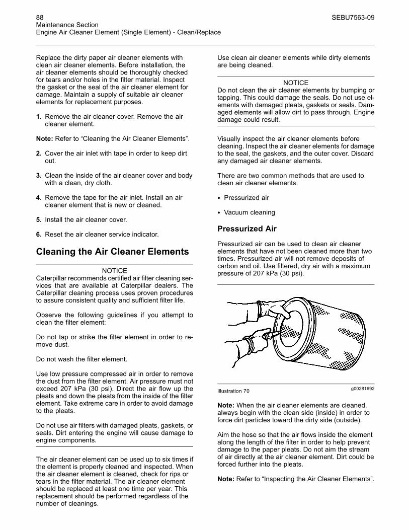
88 SEBU7563-09Maintenance SectionEngine Air Cleaner Element (Single Element) - Clean/Replace
Replace the dirty paper air cleaner elements withclean air cleaner elements. Before installation, theair cleaner elements should be thoroughly checkedfor tears and/or holes in the filter material. Inspectthe gasket or the seal of the air cleaner element fordamage. Maintain a supply of suitable air cleanerelements for replacement purposes.
1. Remove the air cleaner cover. Remove the aircleaner element.
Note: Refer to “Cleaning the Air Cleaner Elements”.
2. Cover the air inlet with tape in order to keep dirtout.
3. Clean the inside of the air cleaner cover and bodywith a clean, dry cloth.
4. Remove the tape for the air inlet. Install an aircleaner element that is new or cleaned.
5. Install the air cleaner cover.
6. Reset the air cleaner service indicator.
Cleaning the Air Cleaner Elements
NOTICECaterpillar recommends certified air filter cleaning ser-vices that are available at Caterpillar dealers. TheCaterpillar cleaning process uses proven proceduresto assure consistent quality and sufficient filter life.
Observe the following guidelines if you attempt toclean the filter element:
Do not tap or strike the filter element in order to re-move dust.
Do not wash the filter element.
Use low pressure compressed air in order to removethe dust from the filter element. Air pressure must notexceed 207 kPa (30 psi). Direct the air flow up thepleats and down the pleats from the inside of the filterelement. Take extreme care in order to avoid damageto the pleats.
Do not use air filters with damaged pleats, gaskets, orseals. Dirt entering the engine will cause damage toengine components.
The air cleaner element can be used up to six times ifthe element is properly cleaned and inspected. Whenthe air cleaner element is cleaned, check for rips ortears in the filter material. The air cleaner elementshould be replaced at least one time per year. Thisreplacement should be performed regardless of thenumber of cleanings.
Use clean air cleaner elements while dirty elementsare being cleaned.
NOTICEDo not clean the air cleaner elements by bumping ortapping. This could damage the seals. Do not use el-ements with damaged pleats, gaskets or seals. Dam-aged elements will allow dirt to pass through. Enginedamage could result.
Visually inspect the air cleaner elements beforecleaning. Inspect the air cleaner elements for damageto the seal, the gaskets, and the outer cover. Discardany damaged air cleaner elements.
There are two common methods that are used toclean air cleaner elements:
• Pressurized air
• Vacuum cleaning
Pressurized Air
Pressurized air can be used to clean air cleanerelements that have not been cleaned more than twotimes. Pressurized air will not remove deposits ofcarbon and oil. Use filtered, dry air with a maximumpressure of 207 kPa (30 psi).
g00281692Illustration 70
Note: When the air cleaner elements are cleaned,always begin with the clean side (inside) in order toforce dirt particles toward the dirty side (outside).
Aim the hose so that the air flows inside the elementalong the length of the filter in order to help preventdamage to the paper pleats. Do not aim the streamof air directly at the air cleaner element. Dirt could beforced further into the pleats.
Note: Refer to “Inspecting the Air Cleaner Elements”.

SEBU7563-09 89Maintenance Section
Engine Air Cleaner Element (Single Element) - Clean/Replace
Vacuum Cleaning
Vacuum cleaning is a good method for cleaningair cleaner elements which require daily cleaningbecause of a dry, dusty environment. Cleaning withpressurized air is recommended prior to vacuumcleaning. Vacuum cleaning will not remove depositsof carbon and oil.
Note: Refer to “Inspecting the Air Cleaner Elements”.
Inspecting the Air Cleaner Elements
g00281693Illustration 71
Inspect the clean, dry air cleaner element. Use a 60watt blue light in a dark room or in a similar facility.Place the blue light in the air cleaner element. Rotatethe air cleaner element. Inspect the air cleanerelement for tears and/or holes. Inspect the air cleanerelement for light that may show through the filtermaterial. If it is necessary in order to confirm theresult, compare the air cleaner element to a new aircleaner element that has the same part number.
Do not use an air cleaner element that has any tearsand/or holes in the filter material. Do not use an aircleaner element with damaged pleats, gaskets orseals. Discard damaged air cleaner elements.
Storing Air Cleaner Elements
If an air cleaner element that passes inspection willnot be used, the air cleaner element can be storedfor future use.
g00281694Illustration 72
Do not use paint, a waterproof cover, or plastic as aprotective covering for storage. An airflow restrictionmay result. To protect against dirt and damage,wrap the air cleaner elements in Volatile CorrosionInhibited (VCI) paper.
Place the air cleaner element into a box for storage.For identification, mark the outside of the box andmark the air cleaner element. Include the followinginformation:
• Date of cleaning
• Number of cleanings
Store the box in a dry location.
Crankcase Air CleanerEngines that are equipped with positive crankcaseventilation have an air cleaner for crankcaseventilation. Clean the air cleaner element or replacethe air cleaner element when the following conditionsoccur:
• The yellow diaphragm enters the red zone.
• The red piston locks in a visible position.
• The air restriction reaches 0.25 kPa (1 inch of H2O).
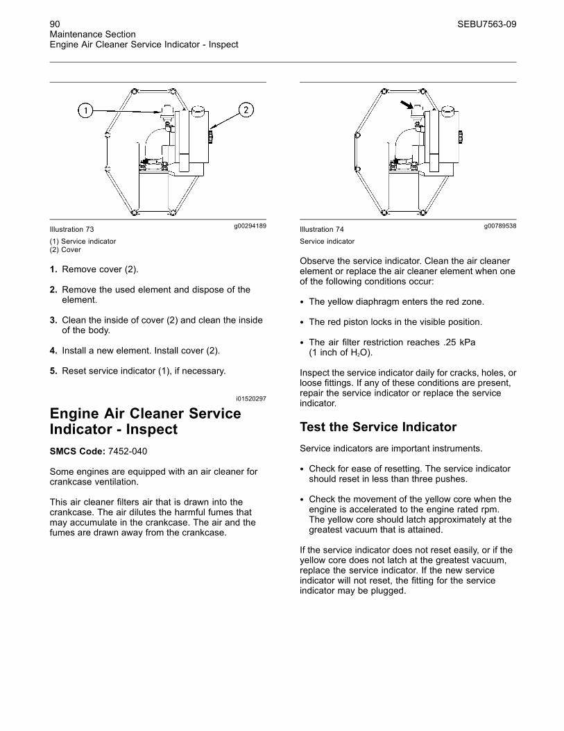
90 SEBU7563-09Maintenance SectionEngine Air Cleaner Service Indicator - Inspect
g00294189Illustration 73(1) Service indicator(2) Cover
1. Remove cover (2).
2. Remove the used element and dispose of theelement.
3. Clean the inside of cover (2) and clean the insideof the body.
4. Install a new element. Install cover (2).
5. Reset service indicator (1), if necessary.
i01520297
Engine Air Cleaner ServiceIndicator - InspectSMCS Code: 7452-040
Some engines are equipped with an air cleaner forcrankcase ventilation.
This air cleaner filters air that is drawn into thecrankcase. The air dilutes the harmful fumes thatmay accumulate in the crankcase. The air and thefumes are drawn away from the crankcase.
g00789538Illustration 74Service indicator
Observe the service indicator. Clean the air cleanerelement or replace the air cleaner element when oneof the following conditions occur:
• The yellow diaphragm enters the red zone.
• The red piston locks in the visible position.
• The air filter restriction reaches .25 kPa(1 inch of H2O).
Inspect the service indicator daily for cracks, holes, orloose fittings. If any of these conditions are present,repair the service indicator or replace the serviceindicator.
Test the Service IndicatorService indicators are important instruments.
• Check for ease of resetting. The service indicatorshould reset in less than three pushes.
• Check the movement of the yellow core when theengine is accelerated to the engine rated rpm.The yellow core should latch approximately at thegreatest vacuum that is attained.
If the service indicator does not reset easily, or if theyellow core does not latch at the greatest vacuum,replace the service indicator. If the new serviceindicator will not reset, the fitting for the serviceindicator may be plugged.
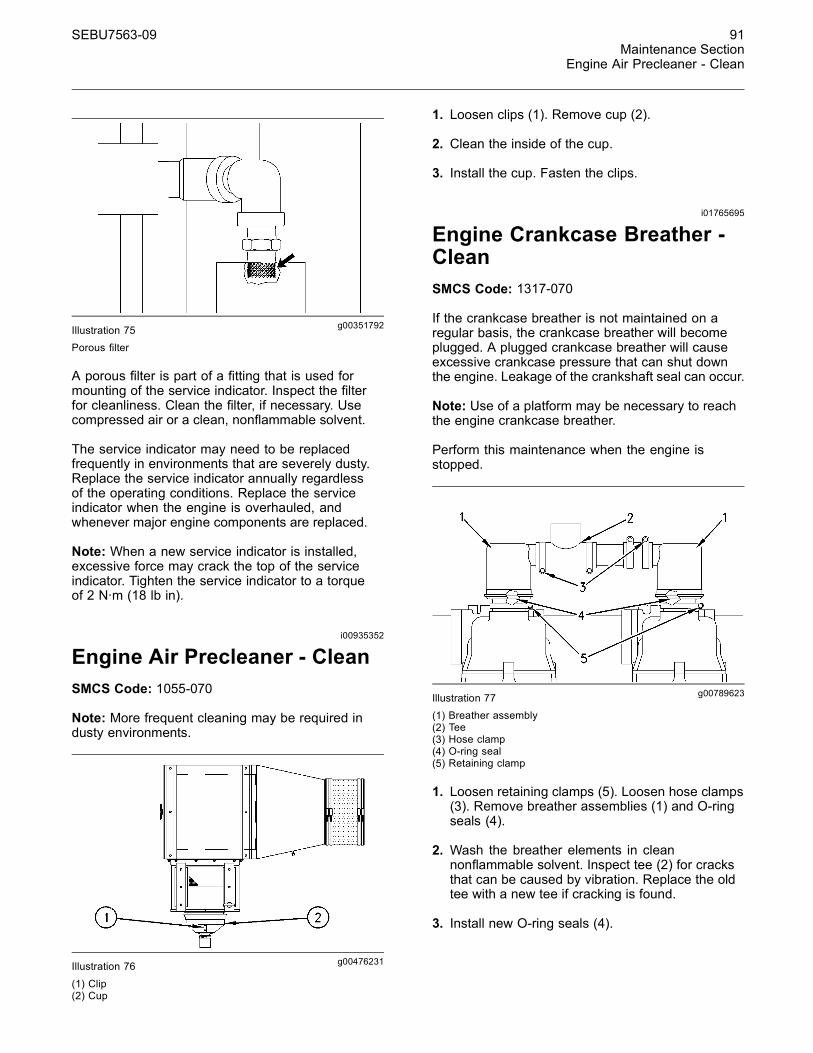
SEBU7563-09 91Maintenance Section
Engine Air Precleaner - Clean
g00351792Illustration 75Porous filter
A porous filter is part of a fitting that is used formounting of the service indicator. Inspect the filterfor cleanliness. Clean the filter, if necessary. Usecompressed air or a clean, nonflammable solvent.
The service indicator may need to be replacedfrequently in environments that are severely dusty.Replace the service indicator annually regardlessof the operating conditions. Replace the serviceindicator when the engine is overhauled, andwhenever major engine components are replaced.
Note: When a new service indicator is installed,excessive force may crack the top of the serviceindicator. Tighten the service indicator to a torqueof 2 N·m (18 lb in).
i00935352
Engine Air Precleaner - CleanSMCS Code: 1055-070
Note: More frequent cleaning may be required industy environments.
g00476231Illustration 76
(1) Clip(2) Cup
1. Loosen clips (1). Remove cup (2).
2. Clean the inside of the cup.
3. Install the cup. Fasten the clips.
i01765695
Engine Crankcase Breather -CleanSMCS Code: 1317-070
If the crankcase breather is not maintained on aregular basis, the crankcase breather will becomeplugged. A plugged crankcase breather will causeexcessive crankcase pressure that can shut downthe engine. Leakage of the crankshaft seal can occur.
Note: Use of a platform may be necessary to reachthe engine crankcase breather.
Perform this maintenance when the engine isstopped.
g00789623Illustration 77
(1) Breather assembly(2) Tee(3) Hose clamp(4) O-ring seal(5) Retaining clamp
1. Loosen retaining clamps (5). Loosen hose clamps(3). Remove breather assemblies (1) and O-ringseals (4).
2. Wash the breather elements in cleannonflammable solvent. Inspect tee (2) for cracksthat can be caused by vibration. Replace the oldtee with a new tee if cracking is found.
3. Install new O-ring seals (4).
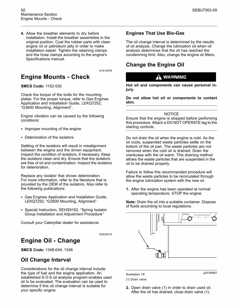
92 SEBU7563-09Maintenance SectionEngine Mounts - Check
4. Allow the breather elements to dry beforeinstallation. Install the breather assemblies in theoriginal position. Coat the rubber parts with cleanengine oil or petroleum jelly in order to makeinstallation easier. Tighten the retaining clampsand the hose clamps according to the engine'sSpecifications manual.
i01612978
Engine Mounts - CheckSMCS Code: 1152-535
Check the torque of the bolts for the mountingplates. For the proper torque, refer to Gas EnginesApplication and Installation Guide, LEKQ7252,“G3600 Mounting, Alignment”.
Engine vibration can be caused by the followingconditions:
• Improper mounting of the engine
• Deterioration of the isolators
Settling of the isolators will result in misalignmentbetween the engine and the driven equipment.Inspect the condition of isolators, if necessary. Keepthe isolators clean and dry. Ensure that the isolatorsare free of oil and contamination. Inspect the isolatorsfor deterioration.
Replace any isolator that shows deterioration.For more information, refer to the literature that isprovided by the OEM of the isolators. Also refer tothe following publications:
• Gas Engines Application and Installation Guide,LEKQ7252, “G3600 Mounting, Alignment”
• Special Instruction, SEHS9162, “Spring IsolatorGroup Installation and Adjustment Procedure”
Consult your Caterpillar dealer for assistance.
i02602019
Engine Oil - ChangeSMCS Code: 1348-044; 1348
Oil Change IntervalConsiderations for the oil change interval includethe type of fuel and the engine application. Anestablished S·O·S oil analysis program enables usedoil to be evaluated. The evaluation can be used todetermine if this oil change interval is suitable foryour specific engine.
Engines That Use Bio-Gas
The oil change interval is determined by the resultsof oil analysis. Change the lubrication oil when oilanalysis determines that the oil has reached thecondemning limit. Also, change the engine oil filters.
Change the Engine Oil
Hot oil and components can cause personal in-jury.
Do not allow hot oil or components to contactskin.
NOTICEEnsure that the engine is stopped before performingthis procedure. Attach a DONOTOPERATE tag to thestarting controls.
Do not drain the oil when the engine is cold. As theoil cools, suspended waste particles settle on thebottom of the oil pan. The waste particles are notremoved when the cold oil is drained. Drain thecrankcase with the oil warm. This draining methodallows the waste particles that are suspended in theoil to be drained properly.
Failure to follow this recommended procedure willallow the waste particles to be recirculated throughthe engine lubrication system with the new oil.
1. After the engine has been operated at normaloperating temperature, STOP the engine.
Note: Drain the oil into a suitable container. Disposeof fluids according to local regulations.
g00789667Illustration 78(1) Drain valve
2. Open drain valve (1) in order to drain used oil.After the oil has drained, close drain valve (1).

SEBU7563-09 93Maintenance Section
Engine Oil Filter - Change
Note: If a suction device is used in order to removethe oil from the oil pan, ensure that the suction deviceis clean. This will prevent dirt from entering the oilpan. Be careful not to strike the engine oil suctiontubes or the piston cooling jets.
3. Clean the oil suction screen.
Note: Approximately 1 L (1 qt) of oil will remain in thehousing after the sump has been completely drained.This oil will pour out of the housing when the coverfor the oil suction screen is removed. Prepare tocatch the oil in a suitable container. Clean up anyspilled oil with rags. DO NOT use absorbent particlesto clean up the oil.
g00789729Illustration 79
(2) Screen assembly
a. Loosen the bolts of the cover for the oil suctionscreen. Remove the cover and the gasket.Discard the old gasket. Slide screen assembly(2) from the tube.
b. Wash the screen assembly in cleannonflammable solvent. Allow the screenassembly to dry before installation.
c. Install the screen assembly. Install a newgasket. Install the cover.
4. Change the engine oil filters. Refer to thisOperation and Maintenance Manual, “Engine OilFilter - Change” topic (Maintenance Section).
NOTICEOnly use oils that are recommended by Caterpillar.For the proper oil to use, refer to this Operation andMaintenance Manual, “Engine Oil” topic (MaintenanceSection).
NOTICEEngine damage can occur if the crankcase is filledabove the “FULL” mark on the oil level gauge (dip-stick).
An overfull crankcase can cause the crankshaft to dipinto the oil. This will reduce the power that is devel-oped and also force air bubbles into the oil. Thesebubbles (foam) can cause the following problems: re-duction of the oil's ability to lubricate, reduction of oilpressure, inadequate cooling, oil blowing out of thecrankcase breathers, and excessive oil consumption.
Excessive oil consumption will cause deposits to formon the pistons and in the combustion chamber. De-posits in the combustion chamber lead to the followingproblems: guttering of the valves, packing of carbonunder the piston rings, and wear of the cylinder liner.
If the oil level is above the “FULL” mark on the oil levelgauge, drain some of the oil immediately.
Note: For the amount of oil to use, refer tothis Operation and Maintenance Manual, “RefillCapacities and Recommendations” (MaintenanceSection).
5. Remove the oil filler cap. Fill the crankcasethrough the oil filler tube only. Clean the oil fillercap. Install the oil filler cap.
6. Follow this Operation and Maintenance Manual,“Starting The Engine” procedure (OperationSection). Operate the engine at low idle for twominutes. Inspect the engine for oil leaks. Ensurethat the oil level is at the “FULL” mark on the“LOW IDLE” side of the oil level gauge.
7. Stop the engine and allow the oil to drain back intothe sump for a minimum of ten minutes.
8. Remove the oil level gauge and check the oil level.Maintain the oil level above the “ADD” mark.
i01520518
Engine Oil Filter - ChangeSMCS Code: 1308-510; 1308
Replace the engine oil filters when the followingconditions are met:
• Every oil change
• The engine oil filter differential pressure reaches100 kPa (15 psi).
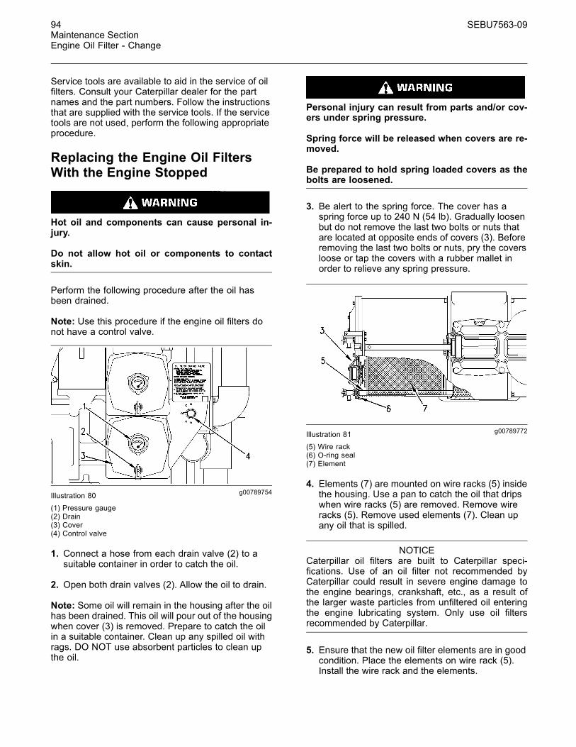
94 SEBU7563-09Maintenance SectionEngine Oil Filter - Change
Service tools are available to aid in the service of oilfilters. Consult your Caterpillar dealer for the partnames and the part numbers. Follow the instructionsthat are supplied with the service tools. If the servicetools are not used, perform the following appropriateprocedure.
Replacing the Engine Oil FiltersWith the Engine Stopped
Hot oil and components can cause personal in-jury.
Do not allow hot oil or components to contactskin.
Perform the following procedure after the oil hasbeen drained.
Note: Use this procedure if the engine oil filters donot have a control valve.
g00789754Illustration 80
(1) Pressure gauge(2) Drain(3) Cover(4) Control valve
1. Connect a hose from each drain valve (2) to asuitable container in order to catch the oil.
2. Open both drain valves (2). Allow the oil to drain.
Note: Some oil will remain in the housing after the oilhas been drained. This oil will pour out of the housingwhen cover (3) is removed. Prepare to catch the oilin a suitable container. Clean up any spilled oil withrags. DO NOT use absorbent particles to clean upthe oil.
Personal injury can result from parts and/or cov-ers under spring pressure.
Spring force will be released when covers are re-moved.
Be prepared to hold spring loaded covers as thebolts are loosened.
3. Be alert to the spring force. The cover has aspring force up to 240 N (54 lb). Gradually loosenbut do not remove the last two bolts or nuts thatare located at opposite ends of covers (3). Beforeremoving the last two bolts or nuts, pry the coversloose or tap the covers with a rubber mallet inorder to relieve any spring pressure.
g00789772Illustration 81
(5) Wire rack(6) O-ring seal(7) Element
4. Elements (7) are mounted on wire racks (5) insidethe housing. Use a pan to catch the oil that dripswhen wire racks (5) are removed. Remove wireracks (5). Remove used elements (7). Clean upany oil that is spilled.
NOTICECaterpillar oil filters are built to Caterpillar speci-fications. Use of an oil filter not recommended byCaterpillar could result in severe engine damage tothe engine bearings, crankshaft, etc., as a result ofthe larger waste particles from unfiltered oil enteringthe engine lubricating system. Only use oil filtersrecommended by Caterpillar.
5. Ensure that the new oil filter elements are in goodcondition. Place the elements on wire rack (5).Install the wire rack and the elements.
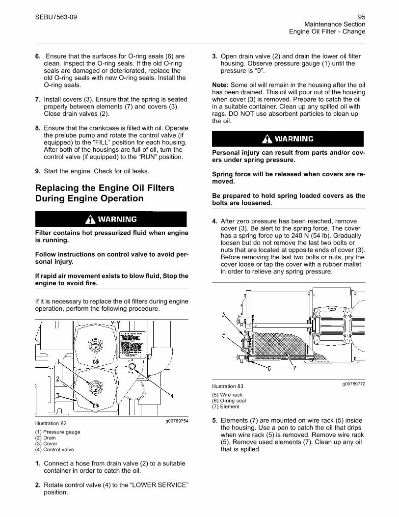
SEBU7563-09 95Maintenance Section
Engine Oil Filter - Change
6. Ensure that the surfaces for O-ring seals (6) areclean. Inspect the O-ring seals. If the old O-ringseals are damaged or deteriorated, replace theold O-ring seals with new O-ring seals. Install theO-ring seals.
7. Install covers (3). Ensure that the spring is seatedproperly between elements (7) and covers (3).Close drain valves (2).
8. Ensure that the crankcase is filled with oil. Operatethe prelube pump and rotate the control valve (ifequipped) to the “FILL” position for each housing.After both of the housings are full of oil, turn thecontrol valve (if equipped) to the “RUN” position.
9. Start the engine. Check for oil leaks.
Replacing the Engine Oil FiltersDuring Engine Operation
Filter contains hot pressurized fluid when engineis running.
Follow instructions on control valve to avoid per-sonal injury.
If rapid air movement exists to blow fluid, Stop theengine to avoid fire.
If it is necessary to replace the oil filters during engineoperation, perform the following procedure.
g00789754Illustration 82
(1) Pressure gauge(2) Drain(3) Cover(4) Control valve
1. Connect a hose from drain valve (2) to a suitablecontainer in order to catch the oil.
2. Rotate control valve (4) to the “LOWER SERVICE”position.
3. Open drain valve (2) and drain the lower oil filterhousing. Observe pressure gauge (1) until thepressure is “0”.
Note: Some oil will remain in the housing after the oilhas been drained. This oil will pour out of the housingwhen cover (3) is removed. Prepare to catch the oilin a suitable container. Clean up any spilled oil withrags. DO NOT use absorbent particles to clean upthe oil.
Personal injury can result from parts and/or cov-ers under spring pressure.
Spring force will be released when covers are re-moved.
Be prepared to hold spring loaded covers as thebolts are loosened.
4. After zero pressure has been reached, removecover (3). Be alert to the spring force. The coverhas a spring force up to 240 N (54 lb). Graduallyloosen but do not remove the last two bolts ornuts that are located at opposite ends of cover (3).Before removing the last two bolts or nuts, pry thecover loose or tap the cover with a rubber malletin order to relieve any spring pressure.
g00789772Illustration 83(5) Wire rack(6) O-ring seal(7) Element
5. Elements (7) are mounted on wire rack (5) insidethe housing. Use a pan to catch the oil that dripswhen wire rack (5) is removed. Remove wire rack(5). Remove used elements (7). Clean up any oilthat is spilled.
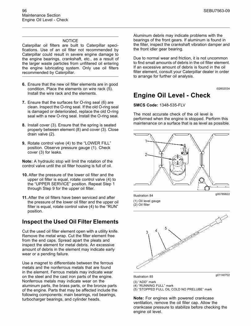
96 SEBU7563-09Maintenance SectionEngine Oil Level - Check
NOTICECaterpillar oil filters are built to Caterpillar speci-fications. Use of an oil filter not recommended byCaterpillar could result in severe engine damage tothe engine bearings, crankshaft, etc., as a result ofthe larger waste particles from unfiltered oil enteringthe engine lubricating system. Only use oil filtersrecommended by Caterpillar.
6. Ensure that the new oil filter elements are in goodcondition. Place the elements on wire rack (5).Install the wire rack and the elements.
7. Ensure that the surfaces for O-ring seal (6) areclean. Inspect the O-ring seal. If the old O-ring sealis damaged or deteriorated, replace the old O-ringseal with a new O-ring seal. Install the O-ring seal.
8. Install cover (3). Ensure that the spring is seatedproperly between element (8) and cover (3). Closedrain valve (2).
9. Rotate control valve (4) to the “LOWER FILL”position. Observe pressure gauge (1). Checkcover (3) for leaks.
Note: A hydraulic stop will limit the rotation of thecontrol valve until the oil filter housing is full of oil.
10.After the pressure of the lower oil filter and theupper oil filter is equal, rotate control valve (4) tothe “UPPER SERVICE” position. Repeat Step 1through Step 9 for the upper oil filter.
11.After the oil filters have been serviced and afterthe pressure of the lower oil filter and the upper oilfilter is equal, rotate control valve (4) to the “RUN”position.
Inspect the Used Oil Filter ElementsCut the used oil filter element open with a utility knife.Remove the metal wrap. Cut the filter element freefrom the end caps. Spread apart the pleats andinspect the element for metal debris. An excessiveamount of debris in the element may indicate earlywear or a pending failure.
Use a magnet to differentiate between the ferrousmetals and the nonferrous metals that are foundin the element. Ferrous metals may indicate wearon the steel and the cast iron parts of the engine.Nonferrous metals may indicate wear on thealuminum parts, the brass parts, or the bronze partsof the engine. Parts that may be affected include thefollowing components: main bearings, rod bearings,turbocharger bearings, and cylinder heads.
Aluminum debris may indicate problems with thebearings of the front gears. If aluminum is found inthe filter, inspect the crankshaft vibration damper andthe front idler gear bearing.
Due to normal wear and friction, it is not uncommonto find small amounts of debris in the oil filter element.If an excessive amount of debris is found in the oilfilter element, consult your Caterpillar dealer in orderto arrange for further oil analysis.
i02602034
Engine Oil Level - CheckSMCS Code: 1348-535-FLV
The most accurate check of the oil level isperformed when the engine is stopped. Perform thismaintenance on a surface that is as level as possible.
g00789822Illustration 84
(1) Oil level gauge(2) Oil filler
g01140702Illustration 85(3) “ADD” mark(4) “RUNNING FULL” mark(5) “STOPPED FULL OIL COLD NO PRELUBE” mark
Note: For engines with powered crankcaseventilation, remove the oil filler cap. Allow thecrankcase pressure to stabilize before checking theengine oil level.
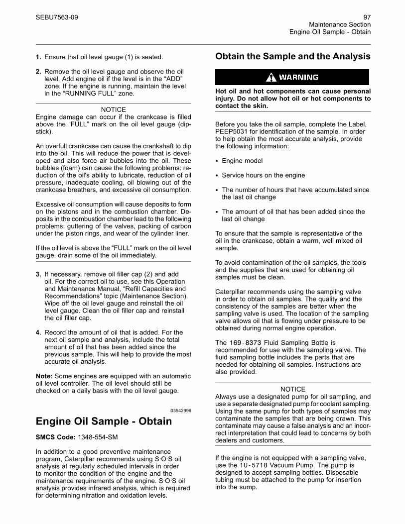
SEBU7563-09 97Maintenance Section
Engine Oil Sample - Obtain
1. Ensure that oil level gauge (1) is seated.
2. Remove the oil level gauge and observe the oillevel. Add engine oil if the level is in the “ADD”zone. If the engine is running, maintain the levelin the “RUNNING FULL” zone.
NOTICEEngine damage can occur if the crankcase is filledabove the “FULL” mark on the oil level gauge (dip-stick).
An overfull crankcase can cause the crankshaft to dipinto the oil. This will reduce the power that is devel-oped and also force air bubbles into the oil. Thesebubbles (foam) can cause the following problems: re-duction of the oil's ability to lubricate, reduction of oilpressure, inadequate cooling, oil blowing out of thecrankcase breathers, and excessive oil consumption.
Excessive oil consumption will cause deposits to formon the pistons and in the combustion chamber. De-posits in the combustion chamber lead to the followingproblems: guttering of the valves, packing of carbonunder the piston rings, and wear of the cylinder liner.
If the oil level is above the “FULL” mark on the oil levelgauge, drain some of the oil immediately.
3. If necessary, remove oil filler cap (2) and addoil. For the correct oil to use, see this Operationand Maintenance Manual, “Refill Capacities andRecommendations” topic (Maintenance Section).Wipe off the oil level gauge and reinstall the oillevel gauge. Clean the oil filler cap and reinstallthe oil filler cap.
4. Record the amount of oil that is added. For thenext oil sample and analysis, include the totalamount of oil that has been added since theprevious sample. This will help to provide the mostaccurate oil analysis.
Note: Some engines are equipped with an automaticoil level controller. The oil level should still bechecked on a daily basis with the oil level gauge.
i03542996
Engine Oil Sample - ObtainSMCS Code: 1348-554-SM
In addition to a good preventive maintenanceprogram, Caterpillar recommends using S·O·S oilanalysis at regularly scheduled intervals in orderto monitor the condition of the engine and themaintenance requirements of the engine. S·O·S oilanalysis provides infrared analysis, which is requiredfor determining nitration and oxidation levels.
Obtain the Sample and the Analysis
Hot oil and hot components can cause personalinjury. Do not allow hot oil or hot components tocontact the skin.
Before you take the oil sample, complete the Label,PEEP5031 for identification of the sample. In orderto help obtain the most accurate analysis, providethe following information:
• Engine model
• Service hours on the engine
• The number of hours that have accumulated sincethe last oil change
• The amount of oil that has been added since thelast oil change
To ensure that the sample is representative of theoil in the crankcase, obtain a warm, well mixed oilsample.
To avoid contamination of the oil samples, the toolsand the supplies that are used for obtaining oilsamples must be clean.
Caterpillar recommends using the sampling valvein order to obtain oil samples. The quality and theconsistency of the samples are better when thesampling valve is used. The location of the samplingvalve allows oil that is flowing under pressure to beobtained during normal engine operation.
The 169-8373 Fluid Sampling Bottle isrecommended for use with the sampling valve. Thefluid sampling bottle includes the parts that areneeded for obtaining oil samples. Instructions arealso provided.
NOTICEAlways use a designated pump for oil sampling, anduse a separate designated pump for coolant sampling.Using the same pump for both types of samples maycontaminate the samples that are being drawn. Thiscontaminate may cause a false analysis and an incor-rect interpretation that could lead to concerns by bothdealers and customers.
If the engine is not equipped with a sampling valve,use the 1U-5718 Vacuum Pump. The pump isdesigned to accept sampling bottles. Disposabletubing must be attached to the pump for insertioninto the sump.
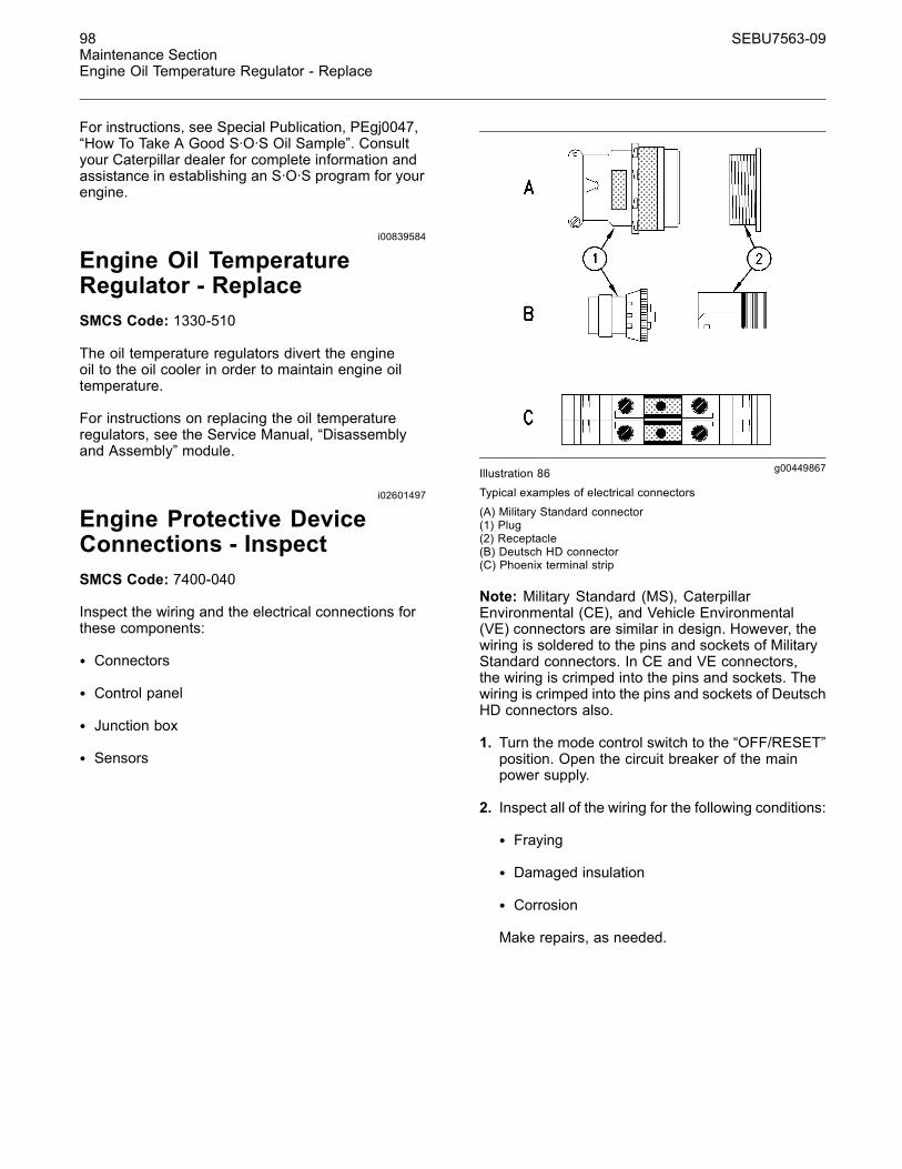
98 SEBU7563-09Maintenance SectionEngine Oil Temperature Regulator - Replace
For instructions, see Special Publication, PEgj0047,“How To Take A Good S·O·S Oil Sample”. Consultyour Caterpillar dealer for complete information andassistance in establishing an S·O·S program for yourengine.
i00839584
Engine Oil TemperatureRegulator - ReplaceSMCS Code: 1330-510
The oil temperature regulators divert the engineoil to the oil cooler in order to maintain engine oiltemperature.
For instructions on replacing the oil temperatureregulators, see the Service Manual, “Disassemblyand Assembly” module.
i02601497
Engine Protective DeviceConnections - InspectSMCS Code: 7400-040
Inspect the wiring and the electrical connections forthese components:
• Connectors
• Control panel
• Junction box
• Sensors
g00449867Illustration 86Typical examples of electrical connectors
(A) Military Standard connector(1) Plug(2) Receptacle(B) Deutsch HD connector(C) Phoenix terminal strip
Note: Military Standard (MS), CaterpillarEnvironmental (CE), and Vehicle Environmental(VE) connectors are similar in design. However, thewiring is soldered to the pins and sockets of MilitaryStandard connectors. In CE and VE connectors,the wiring is crimped into the pins and sockets. Thewiring is crimped into the pins and sockets of DeutschHD connectors also.
1. Turn the mode control switch to the “OFF/RESET”position. Open the circuit breaker of the mainpower supply.
2. Inspect all of the wiring for the following conditions:
• Fraying
• Damaged insulation
• Corrosion
Make repairs, as needed.
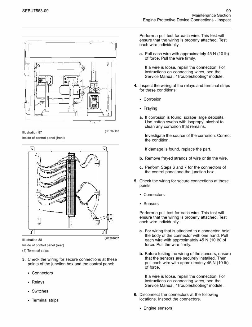
SEBU7563-09 99Maintenance Section
Engine Protective Device Connections - Inspect
g01302112Illustration 87Inside of control panel (front)
g01201607Illustration 88
Inside of control panel (rear)(1) Terminal strips
3. Check the wiring for secure connections at thesepoints of the junction box and the control panel:
• Connectors
• Relays
• Switches
• Terminal strips
Perform a pull test for each wire. This test willensure that the wiring is properly attached. Testeach wire individually.
a. Pull each wire with approximately 45 N (10 lb)of force. Pull the wire firmly.
If a wire is loose, repair the connection. Forinstructions on connecting wires, see theService Manual, “Troubleshooting” module.
4. Inspect the wiring at the relays and terminal stripsfor these conditions:
• Corrosion
• Fraying
a. If corrosion is found, scrape large deposits.Use cotton swabs with isopropyl alcohol toclean any corrosion that remains.
Investigate the source of the corrosion. Correctthe condition.
If damage is found, replace the part.
b. Remove frayed strands of wire or tin the wire.
c. Perform Steps 6 and 7 for the connectors ofthe control panel and the junction box.
5. Check the wiring for secure connections at thesepoints:
• Connectors
• Sensors
Perform a pull test for each wire. This test willensure that the wiring is properly attached. Testeach wire individually.
a. For wiring that is attached to a connector, holdthe body of the connector with one hand. Pulleach wire with approximately 45 N (10 lb) offorce. Pull the wire firmly.
b. Before testing the wiring of the sensors, ensurethat the sensors are securely installed. Thenpull each wire with approximately 45 N (10 lb)of force.
If a wire is loose, repair the connection. Forinstructions on connecting wires, see theService Manual, “Troubleshooting” module.
6. Disconnect the connectors at the followinglocations. Inspect the connectors.
• Engine sensors
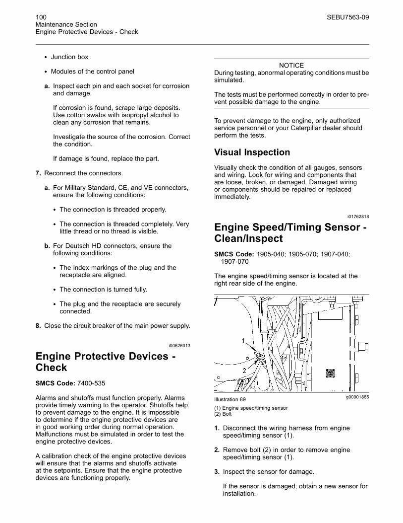
100 SEBU7563-09Maintenance SectionEngine Protective Devices - Check
• Junction box
• Modules of the control panel
a. Inspect each pin and each socket for corrosionand damage.
If corrosion is found, scrape large deposits.Use cotton swabs with isopropyl alcohol toclean any corrosion that remains.
Investigate the source of the corrosion. Correctthe condition.
If damage is found, replace the part.
7. Reconnect the connectors.
a. For Military Standard, CE, and VE connectors,ensure the following conditions:
• The connection is threaded properly.
• The connection is threaded completely. Verylittle thread or no thread is visible.
b. For Deutsch HD connectors, ensure thefollowing conditions:
• The index markings of the plug and thereceptacle are aligned.
• The connection is turned fully.
• The plug and the receptacle are securelyconnected.
8. Close the circuit breaker of the main power supply.
i00626013
Engine Protective Devices -CheckSMCS Code: 7400-535
Alarms and shutoffs must function properly. Alarmsprovide timely warning to the operator. Shutoffs helpto prevent damage to the engine. It is impossibleto determine if the engine protective devices arein good working order during normal operation.Malfunctions must be simulated in order to test theengine protective devices.
A calibration check of the engine protective deviceswill ensure that the alarms and shutoffs activateat the setpoints. Ensure that the engine protectivedevices are functioning properly.
NOTICEDuring testing, abnormal operating conditionsmust besimulated.
The tests must be performed correctly in order to pre-vent possible damage to the engine.
To prevent damage to the engine, only authorizedservice personnel or your Caterpillar dealer shouldperform the tests.
Visual InspectionVisually check the condition of all gauges, sensorsand wiring. Look for wiring and components thatare loose, broken, or damaged. Damaged wiringor components should be repaired or replacedimmediately.
i01762818
Engine Speed/Timing Sensor -Clean/InspectSMCS Code: 1905-040; 1905-070; 1907-040;1907-070
The engine speed/timing sensor is located at theright rear side of the engine.
g00901865Illustration 89
(1) Engine speed/timing sensor(2) Bolt
1. Disconnect the wiring harness from enginespeed/timing sensor (1).
2. Remove bolt (2) in order to remove enginespeed/timing sensor (1).
3. Inspect the sensor for damage.
If the sensor is damaged, obtain a new sensor forinstallation.
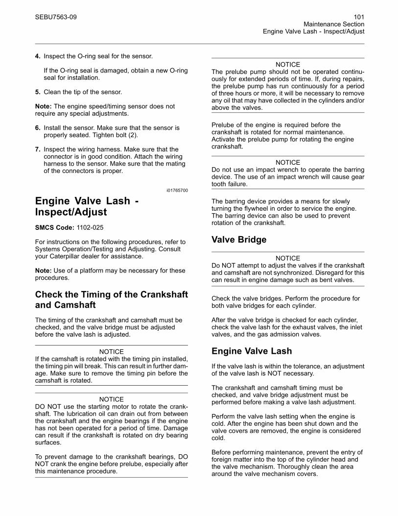
SEBU7563-09 101Maintenance Section
Engine Valve Lash - Inspect/Adjust
4. Inspect the O-ring seal for the sensor.
If the O-ring seal is damaged, obtain a new O-ringseal for installation.
5. Clean the tip of the sensor.
Note: The engine speed/timing sensor does notrequire any special adjustments.
6. Install the sensor. Make sure that the sensor isproperly seated. Tighten bolt (2).
7. Inspect the wiring harness. Make sure that theconnector is in good condition. Attach the wiringharness to the sensor. Make sure that the matingof the connectors is proper.
i01765700
Engine Valve Lash -Inspect/AdjustSMCS Code: 1102-025
For instructions on the following procedures, refer toSystems Operation/Testing and Adjusting. Consultyour Caterpillar dealer for assistance.
Note: Use of a platform may be necessary for theseprocedures.
Check the Timing of the Crankshaftand CamshaftThe timing of the crankshaft and camshaft must bechecked, and the valve bridge must be adjustedbefore the valve lash is adjusted.
NOTICEIf the camshaft is rotated with the timing pin installed,the timing pin will break. This can result in further dam-age. Make sure to remove the timing pin before thecamshaft is rotated.
NOTICEDO NOT use the starting motor to rotate the crank-shaft. The lubrication oil can drain out from betweenthe crankshaft and the engine bearings if the enginehas not been operated for a period of time. Damagecan result if the crankshaft is rotated on dry bearingsurfaces.
To prevent damage to the crankshaft bearings, DONOT crank the engine before prelube, especially afterthis maintenance procedure.
NOTICEThe prelube pump should not be operated continu-ously for extended periods of time. If, during repairs,the prelube pump has run continuously for a periodof three hours or more, it will be necessary to removeany oil that may have collected in the cylinders and/orabove the valves.
Prelube of the engine is required before thecrankshaft is rotated for normal maintenance.Activate the prelube pump for rotating the enginecrankshaft.
NOTICEDo not use an impact wrench to operate the barringdevice. The use of an impact wrench will cause geartooth failure.
The barring device provides a means for slowlyturning the flywheel in order to service the engine.The barring device can also be used to preventrotation of the crankshaft.
Valve Bridge
NOTICEDo NOT attempt to adjust the valves if the crankshaftand camshaft are not synchronized. Disregard for thiscan result in engine damage such as bent valves.
Check the valve bridges. Perform the procedure forboth valve bridges for each cylinder.
After the valve bridge is checked for each cylinder,check the valve lash for the exhaust valves, the inletvalves, and the gas admission valves.
Engine Valve LashIf the valve lash is within the tolerance, an adjustmentof the valve lash is NOT necessary.
The crankshaft and camshaft timing must bechecked, and valve bridge adjustment must beperformed before making a valve lash adjustment.
Perform the valve lash setting when the engine iscold. After the engine has been shut down and thevalve covers are removed, the engine is consideredcold.
Before performing maintenance, prevent the entry offoreign matter into the top of the cylinder head andthe valve mechanism. Thoroughly clean the areaaround the valve mechanism covers.
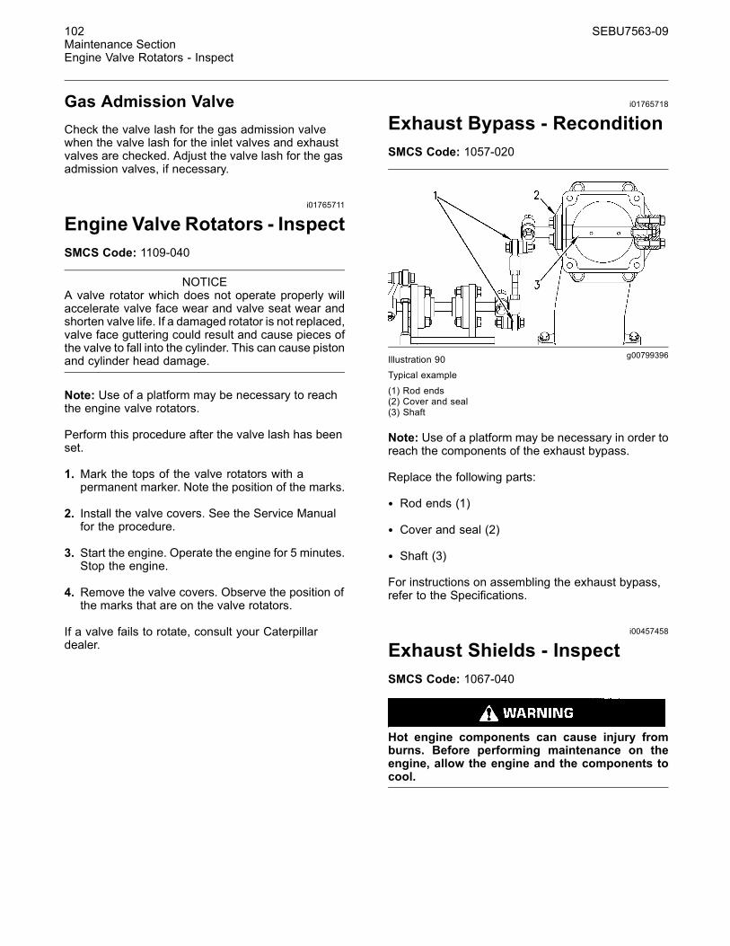
102 SEBU7563-09Maintenance SectionEngine Valve Rotators - Inspect
Gas Admission ValveCheck the valve lash for the gas admission valvewhen the valve lash for the inlet valves and exhaustvalves are checked. Adjust the valve lash for the gasadmission valves, if necessary.
i01765711
Engine Valve Rotators - InspectSMCS Code: 1109-040
NOTICEA valve rotator which does not operate properly willaccelerate valve face wear and valve seat wear andshorten valve life. If a damaged rotator is not replaced,valve face guttering could result and cause pieces ofthe valve to fall into the cylinder. This can cause pistonand cylinder head damage.
Note: Use of a platform may be necessary to reachthe engine valve rotators.
Perform this procedure after the valve lash has beenset.
1. Mark the tops of the valve rotators with apermanent marker. Note the position of the marks.
2. Install the valve covers. See the Service Manualfor the procedure.
3. Start the engine. Operate the engine for 5 minutes.Stop the engine.
4. Remove the valve covers. Observe the position ofthe marks that are on the valve rotators.
If a valve fails to rotate, consult your Caterpillardealer.
i01765718
Exhaust Bypass - ReconditionSMCS Code: 1057-020
g00799396Illustration 90Typical example
(1) Rod ends(2) Cover and seal(3) Shaft
Note: Use of a platform may be necessary in order toreach the components of the exhaust bypass.
Replace the following parts:
• Rod ends (1)
• Cover and seal (2)
• Shaft (3)
For instructions on assembling the exhaust bypass,refer to the Specifications.
i00457458
Exhaust Shields - InspectSMCS Code: 1067-040
Hot engine components can cause injury fromburns. Before performing maintenance on theengine, allow the engine and the components tocool.
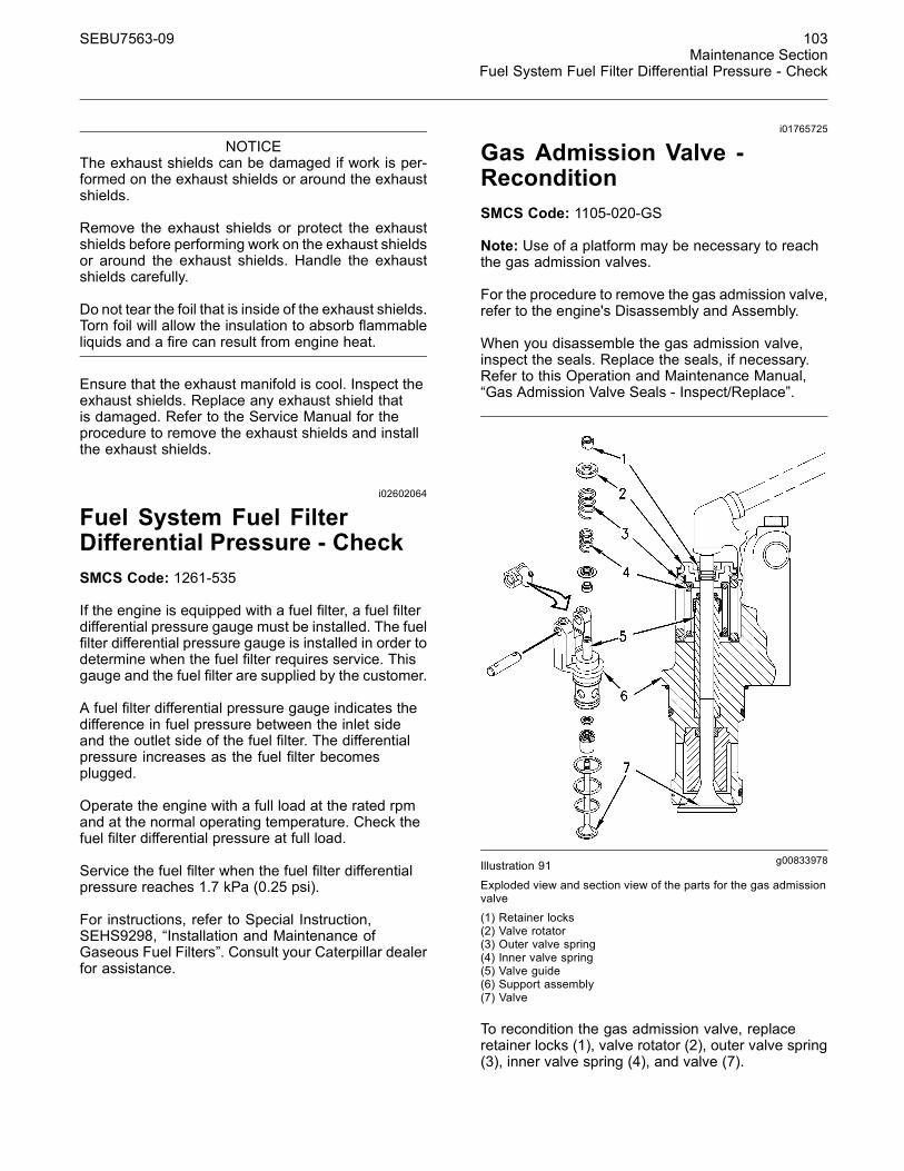
SEBU7563-09 103Maintenance Section
Fuel System Fuel Filter Differential Pressure - Check
NOTICEThe exhaust shields can be damaged if work is per-formed on the exhaust shields or around the exhaustshields.
Remove the exhaust shields or protect the exhaustshields before performing work on the exhaust shieldsor around the exhaust shields. Handle the exhaustshields carefully.
Do not tear the foil that is inside of the exhaust shields.Torn foil will allow the insulation to absorb flammableliquids and a fire can result from engine heat.
Ensure that the exhaust manifold is cool. Inspect theexhaust shields. Replace any exhaust shield thatis damaged. Refer to the Service Manual for theprocedure to remove the exhaust shields and installthe exhaust shields.
i02602064
Fuel System Fuel FilterDifferential Pressure - CheckSMCS Code: 1261-535
If the engine is equipped with a fuel filter, a fuel filterdifferential pressure gauge must be installed. The fuelfilter differential pressure gauge is installed in order todetermine when the fuel filter requires service. Thisgauge and the fuel filter are supplied by the customer.
A fuel filter differential pressure gauge indicates thedifference in fuel pressure between the inlet sideand the outlet side of the fuel filter. The differentialpressure increases as the fuel filter becomesplugged.
Operate the engine with a full load at the rated rpmand at the normal operating temperature. Check thefuel filter differential pressure at full load.
Service the fuel filter when the fuel filter differentialpressure reaches 1.7 kPa (0.25 psi).
For instructions, refer to Special Instruction,SEHS9298, “Installation and Maintenance ofGaseous Fuel Filters”. Consult your Caterpillar dealerfor assistance.
i01765725
Gas Admission Valve -ReconditionSMCS Code: 1105-020-GS
Note: Use of a platform may be necessary to reachthe gas admission valves.
For the procedure to remove the gas admission valve,refer to the engine's Disassembly and Assembly.
When you disassemble the gas admission valve,inspect the seals. Replace the seals, if necessary.Refer to this Operation and Maintenance Manual,“Gas Admission Valve Seals - Inspect/Replace”.
g00833978Illustration 91
Exploded view and section view of the parts for the gas admissionvalve(1) Retainer locks(2) Valve rotator(3) Outer valve spring(4) Inner valve spring(5) Valve guide(6) Support assembly(7) Valve
To recondition the gas admission valve, replaceretainer locks (1), valve rotator (2), outer valve spring(3), inner valve spring (4), and valve (7).
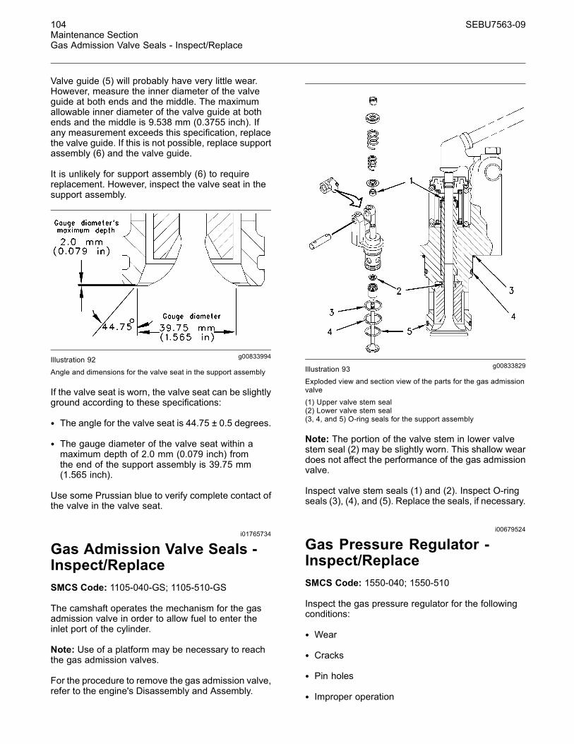
104 SEBU7563-09Maintenance SectionGas Admission Valve Seals - Inspect/Replace
Valve guide (5) will probably have very little wear.However, measure the inner diameter of the valveguide at both ends and the middle. The maximumallowable inner diameter of the valve guide at bothends and the middle is 9.538 mm (0.3755 inch). Ifany measurement exceeds this specification, replacethe valve guide. If this is not possible, replace supportassembly (6) and the valve guide.
It is unlikely for support assembly (6) to requirereplacement. However, inspect the valve seat in thesupport assembly.
g00833994Illustration 92
Angle and dimensions for the valve seat in the support assembly
If the valve seat is worn, the valve seat can be slightlyground according to these specifications:
• The angle for the valve seat is 44.75 ± 0.5 degrees.
• The gauge diameter of the valve seat within amaximum depth of 2.0 mm (0.079 inch) fromthe end of the support assembly is 39.75 mm(1.565 inch).
Use some Prussian blue to verify complete contact ofthe valve in the valve seat.
i01765734
Gas Admission Valve Seals -Inspect/ReplaceSMCS Code: 1105-040-GS; 1105-510-GS
The camshaft operates the mechanism for the gasadmission valve in order to allow fuel to enter theinlet port of the cylinder.
Note: Use of a platform may be necessary to reachthe gas admission valves.
For the procedure to remove the gas admission valve,refer to the engine's Disassembly and Assembly.
g00833829Illustration 93
Exploded view and section view of the parts for the gas admissionvalve(1) Upper valve stem seal(2) Lower valve stem seal(3, 4, and 5) O-ring seals for the support assembly
Note: The portion of the valve stem in lower valvestem seal (2) may be slightly worn. This shallow weardoes not affect the performance of the gas admissionvalve.
Inspect valve stem seals (1) and (2). Inspect O-ringseals (3), (4), and (5). Replace the seals, if necessary.
i00679524
Gas Pressure Regulator -Inspect/ReplaceSMCS Code: 1550-040; 1550-510
Inspect the gas pressure regulator for the followingconditions:
• Wear
• Cracks
• Pin holes
• Improper operation
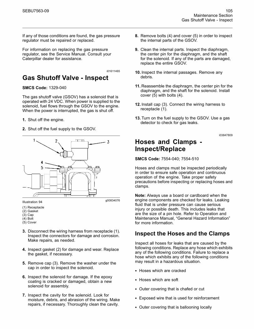
SEBU7563-09 105Maintenance Section
Gas Shutoff Valve - Inspect
If any of those conditions are found, the gas pressureregulator must be repaired or replaced.
For information on replacing the gas pressureregulator, see the Service Manual. Consult yourCaterpillar dealer for assistance.
i01611465
Gas Shutoff Valve - InspectSMCS Code: 1329-040
The gas shutoff valve (GSOV) has a solenoid that isoperated with 24 VDC. When power is supplied to thesolenoid, fuel flows through the GSOV to the engine.When the power is interrupted, the gas is shut off.
1. Shut off the engine.
2. Shut off the fuel supply to the GSOV.
g00834076Illustration 94(1) Receptacle(2) Gasket(3) Cap(4) Bolt(5) Cover
3. Disconnect the wiring harness from receptacle (1).Inspect the connectors for damage and corrosion.Make repairs, as needed.
4. Inspect gasket (2) for damage and wear. Replacethe gasket, if necessary.
5. Remove cap (3). Remove the washer under thecap in order to inspect the solenoid.
6. Inspect the solenoid for damage. If the epoxycoating is cracked or damaged, obtain a newsolenoid for assembly.
7. Inspect the cavity for the solenoid. Look formoisture, debris, and abrasion of the wiring. Makerepairs, if necessary. Thoroughly clean the cavity.
8. Remove bolts (4) and cover (5) in order to inspectthe internal parts of the GSOV.
9. Clean the internal parts. Inspect the diaphragm,the center pin for the diaphragm, and the shaftfor the solenoid. If any of the parts are damaged,replace the entire GSOV.
10. Inspect the internal passages. Remove anydebris.
11.Reassemble the diaphragm, the center pin for thediaphragm, and the shaft for the solenoid. Installcover (5) with bolts (4).
12. Install cap (3). Connect the wiring harness toreceptacle (1).
13. Turn on the fuel supply to the GSOV. Use a gasdetector to check for gas leaks.
i03847809
Hoses and Clamps -Inspect/ReplaceSMCS Code: 7554-040; 7554-510
Hoses and clamps must be inspected periodicallyin order to ensure safe operation and continuousoperation of the engine. Take proper safetyprecautions before inspecting or replacing hoses andclamps.
Note: Always use a board or cardboard when theengine components are checked for leaks. Leakingfluid that is under pressure can cause seriousinjury or possible death. This includes leaks thatare the size of a pin hole. Refer to Operation andMaintenance Manual, “General Hazard Information”for more information.
Inspect the Hoses and the ClampsInspect all hoses for leaks that are caused by thefollowing conditions. Replace any hose which exhibitsany of the following conditions. Failure to replace ahose which exhibits any of the following conditionsmay result in a hazardous situation.
• Hoses which are cracked
• Hoses which are soft
• Outer covering that is chafed or cut
• Exposed wire that is used for reinforcement
• Outer covering that is ballooning locally
106 SEBU7563-09Maintenance SectionHoses and Clamps - Inspect/Replace
• Flexible part of the hose that is kinked or crushed
• Armoring that is embedded in the outer covering
• Hoses which exhibit signs of leakage which are notthe result of loose couplings or clamps
Inspect all clamps for the following conditions.Replace any clamp which exhibits signs of any of thefollowing conditions.
• Cracking
• Looseness
• Damage
Inspect all couplings for leaks. Replace any couplingwhich exhibits signs of leaks.
Each installation application can be different. Thedifferences depend on the following factors:
• Type of hose
• Type of fitting material
• Anticipated expansion and contraction of the hose
• Anticipated expansion and contraction of thefittings
Due to extreme temperature changes, the hose willheat set. Heat setting causes hose clamps to loosen.This can result in leaks. A constant torque hoseclamp will help to prevent loose hose clamps.
Replace hoses that are cracked or soft. Replacehoses that show signs of leakage. Replace hosesthat show signs of damage. Replace hose clampsthat are cracked or damaged. Tighten or replacehose clamps which are loose.
Replace the Hoses and the Clamps
NOTICECare must be taken to ensure that fluids are containedduring performance of inspection, maintenance, test-ing, adjusting and repair of the product. Be prepared tocollect the fluid with suitable containers before open-ing any compartment or disassembling any compo-nent containing fluids.
Refer to Special Publication, NENG2500, “CaterpillarDealer Service Tool Catalog” or refer to Special Pub-lication, PECJ0003, “Caterpillar Shop Supplies andTools Catalog” for tools and supplies suitable to col-lect and contain fluids on Caterpillar products.
Dispose of all fluids according to local regulations andmandates.
Cooling System
Pressurized System: Hot coolant can cause seri-ous burns. To open the cooling system filler cap,stop the engine and wait until the cooling systemcomponents are cool. Loosen the cooling systempressure cap slowly in order to relieve the pres-sure.
Personal injury can result from removing hoses orfittings in a pressure system.
Failure to relieve pressure can cause personal in-jury.
Do not disconnect or remove hoses or fittings un-til all pressure in the system has been relieved.
1. Stop the engine.
2. Allow the engine to cool.
3. Before servicing a coolant hose, slowly loosen thefiller cap for the cooling system in order to relieveany pressure.
4. Remove the filler cap for the cooling system.
5. Drain the coolant from the cooling system to alevel that is below the hose that is being replaced.Drain the coolant into a suitable clean container.The coolant can be reused.
6. Remove the hose clamps.
SEBU7563-09 107Maintenance Section
Hoses and Clamps - Inspect/Replace
7. Disconnect the old hose.
8. Replace the old hose with a new hose.
9. Install hose clamps which have been inspected orinstall new hose clamps. Refer to Specifications,SENR3130, “Torque Specifications”, “HoseClamps” for information about selecting andinstalling the proper hose clamps.
10.Refill the cooling system.
11.Clean the filler cap for the cooling system. Inspectthe gaskets on the filler cap. Replace the filler capif the gaskets are damaged. Install the filler cap.
12.Start the engine. Inspect the cooling system forleaks.
Fuel System
Personal injury can result from removing hoses orfittings in a pressure system.
Failure to relieve pressure can cause personal in-jury.
Do not disconnect or remove hoses or fittings un-til all pressure in the system has been relieved.
Contact with high pressure fuel may cause fluidpenetration and burn hazards. High pressure fu-el spray may cause a fire hazard. Failure to fol-low these inspection, maintenance and service in-structions may cause personal injury or death.
NOTICEDo not bend or strike high pressure lines. Do not in-stall bent or damaged lines, tubes or hoses. Repairany loose or damaged fuel and oil lines, tubes andhoses. Leaks can cause fires. Inspect all lines, tubesand hoses carefully. Tighten all connections to the rec-ommended torque.
NOTICEDo not allow dirt to enter the fuel system. Thoroughlyclean the area around a fuel system component thatwill be disconnected. Fit a suitable cover over any dis-connected fuel system components.
Note: High pressure fuel lines may be installedbetween the high pressure fuel pump and the fuelinjectors. High pressure fuel lines are constantlycharged with high pressure. Do not check the highpressure fuel lines with the engine or the startingmotor in operation. Wait for 10 minutes after theengine stops before you perform any service or repairon high pressure fuel lines in order to allow pressureto be purged.
1. Drain the fuel from the fuel system to a level thatis below the hose that is being replaced.
2. Remove the hose clamps.
3. Disconnect the old hose.
4. Replace the old hose with a new hose.
5. Install hose clamps which have been inspected orinstall new hose clamps. Refer to Specifications,SENR3130, “Torque Specifications”, “HoseClamps” for information about selecting andinstalling the proper hose clamps.
6. Carefully inspect the engine for any spilled fuel.Make sure that no fuel remains on or close to theengine.
Note: Fuel must be added to the fuel system aheadof the fuel filter.
7. Refill the fuel system. Refer to this Operation andMaintenance Manual, “Fuel System - Prime” forinformation about priming the engine with fuel.
8. Start the engine. Inspect the fuel system for leaks.
Lubrication System
Hot oil and hot components can cause personalinjury. Do not allow hot oil or hot components tocontact the skin.
1. Drain the oil from the lubrication system to a levelthat is below the hose that is being replaced.
2. Remove the hose clamps.
3. Disconnect the old hose.
4. Replace the old hose with a new hose.
5. Install hose clamps which have been inspected orinstall new hose clamps. Refer to Specifications,SENR3130, “Torque Specifications”, “HoseClamps” for information about selecting andinstalling the proper hose clamps.

108 SEBU7563-09Maintenance SectionIgnition System Spark Plugs - Check/Adjust
6. Refill the lubrication system. Refer to thisOperation and Maintenance Manual, “EngineOil Level - Check” in order to ensure that thelubrication system is filled with the proper amountof engine oil.
7. Start the engine. Inspect the lubrication systemfor leaks.
Air System
1. Remove the hose clamps.
2. Disconnect the old hose.
3. Replace the old hose with a new hose.
4. Install hose clamps which have been inspected orinstall new hose clamps. Refer to Specifications,SENR3130, “Torque Specifications”, “HoseClamps” for information about selecting andinstalling the proper hose clamps.
5. Start the engine. Inspect the air lines for leaks.
i03915150
Ignition System Spark Plugs -Check/AdjustSMCS Code: 1555-535
Maintenance of the spark plugs is required in order toobtain the following benefits:
• Normal fuel consumption
• Normal levels of emissions
• Maximum service life of the spark plugs
The service life of the spark plugs is affected byfouling due to deposits from the oil and by peakvoltage. Maintenance of the ignition system is alsoaffected by voltage. Higher voltage is required byhigher inlet manifold air pressure and a highercompression ratio. Higher voltage reduces theservice life of components such as spark plug wiresand transformers.
Removing the Spark Plug
g00823378Illustration 95(1) Harness connector(2) Bolt(3) Transformer(4) O-ring seal(5) Extension(6) Spark plug
1. Ensure that the mode control switch is in the“STOP” or “OFF/RESET” position.
NOTICEPulling on the wiring harness may break the wires. Donot pull on the wiring harness.
2. Remove the lockwire. Disconnect harnessconnector (1). Use pliers to turn the connectorcounterclockwise.
3. Remove bolts (2).
4. Remove transformer (3). Inspect O-ring seal (4).If the O-ring seal is worn or damaged, discardthe O-ring seal and use a new O-ring seal forassembly.
5. Remove extension (5).
Pressurized air can cause personal injury. Whenpressurized air is used for cleaning, wear a pro-tective face shield, protective clothing, and pro-tective shoes.
6. Debris may have collected near the spark plug.Thoroughly remove any debris. Use compressedair. The maximum air pressure for cleaningpurposes must be below 207 kPa (30 psi). Ensurethat the area around the spark plug is clean andfree of dirt and debris.

SEBU7563-09 109Maintenance Section
Ignition System Spark Plugs - Check/Adjust
7. Use a 4C-4601 Spark Plug Socket and anextension to loosen spark plug (6). After the sparkplug has been loosened, remove the spark plug byhand in order to detect problems with the threads.After the spark plug has been removed, discardthe used gasket.
NOTICEThe use of a thread tap will removemetal unnecessar-ily. This will also reduce the heat transfer for the sparkplug. This can result in a reduction of the spark plugservice life and a reduction of the detonation margin.
If the spark plug resists removal by hand, applypenetrating oil to the threads. Use the wrench andapply steady pressure to the spark plug until thespark plug is loose.
If the spark plug cannot be removed by hand, cleanthe threads with 9U-7511 Spark Plug Seat Cleaner.This tool scrapes debris from the seat and from thethreads.
Inspecting the Spark Plug
g00838300Illustration 96
(1) Terminal post(2) Insulator(3) Shell(4) Gasket(5) Electrode
Inspect the spark plug closely for damage. Thecondition of the spark plug can indicate the operatingcondition of the engine.
Terminal post (1) must not move. If the terminal postcan be moved by hand, discard the spark plug.
Inspect insulator (2) for cracks. If a crack is found,discard the spark plug.
Faint marks may extend from shell (3) onto theinsulator. The marks may be a result of corona thatforms at the top of the shell. The corona developswhen a high voltage potential ionizes the air thatsurrounds a conductor, which is a normal condition.This condition is not an indication of leakage betweenthe shell and the insulator.
Inspect shell (3) for damage. Cracks can be causedby overtightening the spark plug. Overtightening canalso loosen the shell. Discard any spark plug that hasa shell that is cracked or loose.
Inspect electrode (5) for excessive wear. Flatsurfaces with sharp edges provide the best conditionsfor creating a spark. An electrode will become wornfrom use. The surfaces erode. A higher voltage isrequired in order to produce a spark.
g00760569Illustration 97
(6) Precious metal pads on the electrode and the ground strap
Caterpillar spark plugs have precious metal pads (6)on the tips of the electrode and the ground strap.This material will gradually erode.
Replace the spark plug if the precious metal is wornoff.
Light brown deposits or beige deposits around theelectrode are produced by normal operation. Whitedeposits or gray deposits may be caused by thefollowing substances:
• Excessive oil
• Use of the wrong oil
• A substance that is introduced through the fuelsystem or the air system
A spark plug can operate despite a buildup ofash. However, a buildup of ash can cover theelectrode gap. The buildup will cause misfire. Largedeposits may retain heat which can cause prematurefuel ignition. Premature fuel ignition can lead touncontrollable detonation.
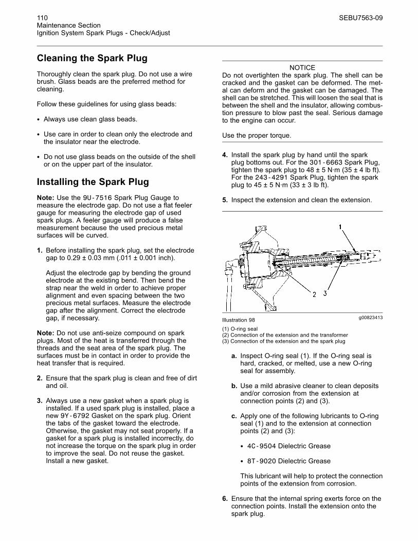
110 SEBU7563-09Maintenance SectionIgnition System Spark Plugs - Check/Adjust
Cleaning the Spark PlugThoroughly clean the spark plug. Do not use a wirebrush. Glass beads are the preferred method forcleaning.
Follow these guidelines for using glass beads:
• Always use clean glass beads.
• Use care in order to clean only the electrode andthe insulator near the electrode.
• Do not use glass beads on the outside of the shellor on the upper part of the insulator.
Installing the Spark PlugNote: Use the 9U-7516 Spark Plug Gauge tomeasure the electrode gap. Do not use a flat feelergauge for measuring the electrode gap of usedspark plugs. A feeler gauge will produce a falsemeasurement because the used precious metalsurfaces will be curved.
1. Before installing the spark plug, set the electrodegap to 0.29 ± 0.03 mm (.011 ± 0.001 inch).
Adjust the electrode gap by bending the groundelectrode at the existing bend. Then bend thestrap near the weld in order to achieve properalignment and even spacing between the twoprecious metal surfaces. Measure the electrodegap after the alignment. Correct the electrodegap, if necessary.
Note: Do not use anti-seize compound on sparkplugs. Most of the heat is transferred through thethreads and the seat area of the spark plug. Thesurfaces must be in contact in order to provide theheat transfer that is required.
2. Ensure that the spark plug is clean and free of dirtand oil.
3. Always use a new gasket when a spark plug isinstalled. If a used spark plug is installed, place anew 9Y-6792 Gasket on the spark plug. Orientthe tabs of the gasket toward the electrode.Otherwise, the gasket may not seat properly. If agasket for a spark plug is installed incorrectly, donot increase the torque on the spark plug in orderto improve the seal. Do not reuse the gasket.Install a new gasket.
NOTICEDo not overtighten the spark plug. The shell can becracked and the gasket can be deformed. The met-al can deform and the gasket can be damaged. Theshell can be stretched. This will loosen the seal that isbetween the shell and the insulator, allowing combus-tion pressure to blow past the seal. Serious damageto the engine can occur.
Use the proper torque.
4. Install the spark plug by hand until the sparkplug bottoms out. For the 301-6663 Spark Plug,tighten the spark plug to 48 ± 5 N·m (35 ± 4 lb ft).For the 243-4291 Spark Plug, tighten the sparkplug to 45 ± 5 N·m (33 ± 3 lb ft).
5. Inspect the extension and clean the extension.
g00823413Illustration 98(1) O-ring seal(2) Connection of the extension and the transformer(3) Connection of the extension and the spark plug
a. Inspect O-ring seal (1). If the O-ring seal ishard, cracked, or melted, use a new O-ringseal for assembly.
b. Use a mild abrasive cleaner to clean depositsand/or corrosion from the extension atconnection points (2) and (3).
c. Apply one of the following lubricants to O-ringseal (1) and to the extension at connectionpoints (2) and (3):
• 4C-9504 Dielectric Grease
• 8T-9020 Dielectric Grease
This lubricant will help to protect the connectionpoints of the extension from corrosion.
6. Ensure that the internal spring exerts force on theconnection points. Install the extension onto thespark plug.
SEBU7563-09 111Maintenance Section
Ignition System Spark Plugs - Replace
7. Ensure that the transformer assembly is clean andfree of dirt and oil. Assemble the extension intothe transformer. Install the transformer.
8. Connect the wiring harness. Tighten the connectorclockwise with pliers until the connector cannot beloosened by hand. Replace the lockwire.
i01612988
Ignition System Spark Plugs -ReplaceSMCS Code: 1555-510
Remove the used spark plugs. Install new sparkplugs.
For instructions on removing and installing sparkplugs, refer to this Operation and MaintenanceManual, “Ignition System Spark Plugs - Check/Adjust”topic (Maintenance Section).
i01935380
Inlet Air System - InspectSMCS Code: 1058-040; 1071-040; 1087-040
Use of a platform may be necessary to inspect thefollowing components of the air inlet system:
• Piping between the air cleaner and the turbocharger
• Rubber hoses in the air lines
• Turbocharger
• Piping between the turbocharger and theaftercooler
• Aftercooler
• Connection of the aftercooler to the air plenum
• Connection of the air plenum to the cylinder head
Inspect the components for the following conditions:
• Cracks
• Leaks
• Loose connections
• Debris
Ensure that all of the connections are secure. Ensurethat the components are in good condition and freeof debris.
Make repairs, if necessary. For information regardingremoval and installation of the components, referto Service Manual, “Disassembly and Assembly”.Consult your Caterpillar dealer for assistance.
i00683392
Inlet Gas Manifold and Piping -Inspect/ReplaceSMCS Code: 1550-040; 1550-510
Inspect the components of the fuel inlet system forthe following conditions:
• Cracks
• Deterioration
• Leaks
• Loose connections
• Wear
Inspect the following components:
• Fuel lines from the source to the gas regulator
• Fuel lines from the gas regulator to the fuel inlet
• Fuel inlet
• Control valve
• Fuel manifold
• Connections of the fuel manifold and the fuel lines
• Connections of the fuel lines to the orifice
• Connections of the fuel lines to the cylinder head
• Connections of the fuel lines to the precombustionchamber
• Fuel pressure sensor
• Fuel temperature sensor
Ensure that all of the connections are secure. Ensurethat the components of the fuel system are in goodcondition.
Make repairs, if necessary. For information regardingremoval and installation of the components, see theService Manual. Consult your Caterpillar dealer forassistance.
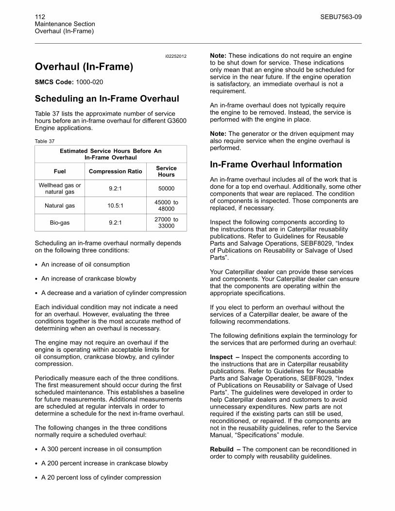
112 SEBU7563-09Maintenance SectionOverhaul (In-Frame)
i02252012
Overhaul (In-Frame)SMCS Code: 1000-020
Scheduling an In-Frame OverhaulTable 37 lists the approximate number of servicehours before an in-frame overhaul for different G3600Engine applications.
Table 37
Estimated Service Hours Before AnIn-Frame Overhaul
Fuel Compression Ratio ServiceHours
Wellhead gas ornatural gas 9.2:1 50000
Natural gas 10.5:1 45000 to48000
Bio-gas 9.2:1 27000 to33000
Scheduling an in-frame overhaul normally dependson the following three conditions:
• An increase of oil consumption
• An increase of crankcase blowby
• A decrease and a variation of cylinder compression
Each individual condition may not indicate a needfor an overhaul. However, evaluating the threeconditions together is the most accurate method ofdetermining when an overhaul is necessary.
The engine may not require an overhaul if theengine is operating within acceptable limits foroil consumption, crankcase blowby, and cylindercompression.
Periodically measure each of the three conditions.The first measurement should occur during the firstscheduled maintenance. This establishes a baselinefor future measurements. Additional measurementsare scheduled at regular intervals in order todetermine a schedule for the next in-frame overhaul.
The following changes in the three conditionsnormally require a scheduled overhaul:
• A 300 percent increase in oil consumption
• A 200 percent increase in crankcase blowby
• A 20 percent loss of cylinder compression
Note: These indications do not require an engineto be shut down for service. These indicationsonly mean that an engine should be scheduled forservice in the near future. If the engine operationis satisfactory, an immediate overhaul is not arequirement.
An in-frame overhaul does not typically requirethe engine to be removed. Instead, the service isperformed with the engine in place.
Note: The generator or the driven equipment mayalso require service when the engine overhaul isperformed.
In-Frame Overhaul InformationAn in-frame overhaul includes all of the work that isdone for a top end overhaul. Additionally, some othercomponents that wear are replaced. The conditionof components is inspected. Those components arereplaced, if necessary.
Inspect the following components according tothe instructions that are in Caterpillar reusabilitypublications. Refer to Guidelines for ReusableParts and Salvage Operations, SEBF8029, “Indexof Publications on Reusability or Salvage of UsedParts”.
Your Caterpillar dealer can provide these servicesand components. Your Caterpillar dealer can ensurethat the components are operating within theappropriate specifications.
If you elect to perform an overhaul without theservices of a Caterpillar dealer, be aware of thefollowing recommendations.
The following definitions explain the terminology forthe services that are performed during an overhaul:
Inspect – Inspect the components according tothe instructions that are in Caterpillar reusabilitypublications. Refer to Guidelines for ReusableParts and Salvage Operations, SEBF8029, “Indexof Publications on Reusability or Salvage of UsedParts”. The guidelines were developed in order tohelp Caterpillar dealers and customers to avoidunnecessary expenditures. New parts are notrequired if the existing parts can still be used,reconditioned, or repaired. If the components arenot in the reusability guidelines, refer to the ServiceManual, “Specifications” module.
Rebuild – The component can be reconditioned inorder to comply with reusability guidelines.
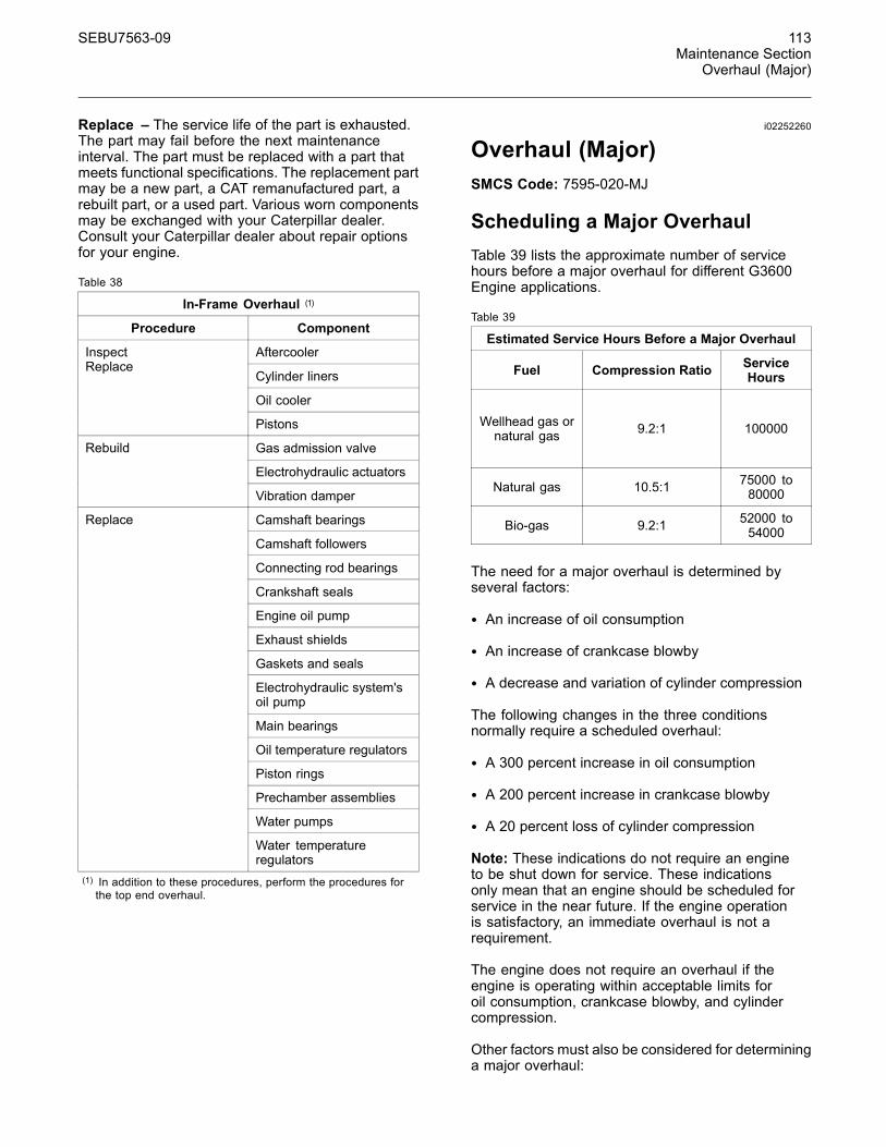
SEBU7563-09 113Maintenance Section
Overhaul (Major)
Replace – The service life of the part is exhausted.The part may fail before the next maintenanceinterval. The part must be replaced with a part thatmeets functional specifications. The replacement partmay be a new part, a CAT remanufactured part, arebuilt part, or a used part. Various worn componentsmay be exchanged with your Caterpillar dealer.Consult your Caterpillar dealer about repair optionsfor your engine.
Table 38
In-Frame Overhaul (1)
Procedure Component
Aftercooler
Cylinder liners
Oil cooler
InspectReplace
Pistons
Gas admission valve
Electrohydraulic actuators
Rebuild
Vibration damper
Camshaft bearings
Camshaft followers
Connecting rod bearings
Crankshaft seals
Engine oil pump
Exhaust shields
Gaskets and seals
Electrohydraulic system'soil pump
Main bearings
Oil temperature regulators
Piston rings
Prechamber assemblies
Water pumps
Replace
Water temperatureregulators
(1) In addition to these procedures, perform the procedures forthe top end overhaul.
i02252260
Overhaul (Major)SMCS Code: 7595-020-MJ
Scheduling a Major OverhaulTable 39 lists the approximate number of servicehours before a major overhaul for different G3600Engine applications.
Table 39
Estimated Service Hours Before a Major Overhaul
Fuel Compression Ratio ServiceHours
Wellhead gas ornatural gas 9.2:1 100000
Natural gas 10.5:1 75000 to80000
Bio-gas 9.2:1 52000 to54000
The need for a major overhaul is determined byseveral factors:
• An increase of oil consumption
• An increase of crankcase blowby
• A decrease and variation of cylinder compression
The following changes in the three conditionsnormally require a scheduled overhaul:
• A 300 percent increase in oil consumption
• A 200 percent increase in crankcase blowby
• A 20 percent loss of cylinder compression
Note: These indications do not require an engineto be shut down for service. These indicationsonly mean that an engine should be scheduled forservice in the near future. If the engine operationis satisfactory, an immediate overhaul is not arequirement.
The engine does not require an overhaul if theengine is operating within acceptable limits foroil consumption, crankcase blowby, and cylindercompression.
Other factors must also be considered for determininga major overhaul:
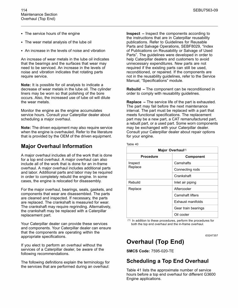
114 SEBU7563-09Maintenance SectionOverhaul (Top End)
• The service hours of the engine
• The wear metal analysis of the lube oil
• An increase in the levels of noise and vibration
An increase of wear metals in the lube oil indicatesthat the bearings and the surfaces that wear mayneed to be serviced. An increase in the levels ofnoise and vibration indicates that rotating partsrequire service.
Note: It is possible for oil analysis to indicate adecrease of wear metals in the lube oil. The cylinderliners may be worn so that polishing of the boreoccurs. Also, the increased use of lube oil will dilutethe wear metals.
Monitor the engine as the engine accumulatesservice hours. Consult your Caterpillar dealer aboutscheduling a major overhaul.
Note: The driven equipment may also require servicewhen the engine is overhauled. Refer to the literaturethat is provided by the OEM of the driven equipment.
Major Overhaul InformationA major overhaul includes all of the work that is donefor a top end overhaul. A major overhaul can alsoinclude all of the work that is done for an in-frameoverhaul. A major overhaul includes additional partsand labor. Additional parts and labor may be requiredin order to completely rebuild the engine. In somecases, the engine is relocated for disassembly.
For the major overhaul, bearings, seals, gaskets, andcomponents that wear are disassembled. The partsare cleaned and inspected. If necessary, the partsare replaced. The crankshaft is measured for wear.The crankshaft may require regrinding. Alternatively,the crankshaft may be replaced with a Caterpillarreplacement part.
Your Caterpillar dealer can provide these servicesand components. Your Caterpillar dealer can ensurethat the components are operating within theappropriate specifications.
If you elect to perform an overhaul without theservices of a Caterpillar dealer, be aware of thefollowing recommendations.
The following definitions explain the terminology forthe services that are performed during an overhaul:
Inspect – Inspect the components according tothe instructions that are in Caterpillar reusabilitypublications. Refer to Guidelines for ReusableParts and Salvage Operations, SEBF8029, “Indexof Publications on Reusability or Salvage of UsedParts”. The guidelines were developed in order tohelp Caterpillar dealers and customers to avoidunnecessary expenditures. New parts are notrequired if the existing parts can still be used,reconditioned, or repaired. If the components arenot in the reusability guidelines, refer to the ServiceManual, “Specifications” module.
Rebuild – The component can be reconditioned inorder to comply with reusability guidelines.
Replace – The service life of the part is exhausted.The part may fail before the next maintenanceinterval. The part must be replaced with a part thatmeets functional specifications. The replacementpart may be a new part, a CAT remanufactured part,a rebuilt part, or a used part. Some worn componentsmay be exchanged with your Caterpillar dealer.Consult your Caterpillar dealer about repair optionsfor your engine.
Table 40
Major Overhaul(1)
Procedure Component
Camshafts
Connecting rods
InspectReplace
Crankshaft
Rebuild Inlet air piping
Aftercooler
Camshaft lifters
Exhaust manifolds
Gear train bearings
Replace
Oil cooler(1) In addition to these procedures, perform the procedures forboth the top end overhaul and the in-frame overhaul.
i03247357
Overhaul (Top End)SMCS Code: 7595-020-TE
Scheduling a Top End OverhaulTable 41 lists the approximate number of servicehours before a top end overhaul for different G3600Engine applications.
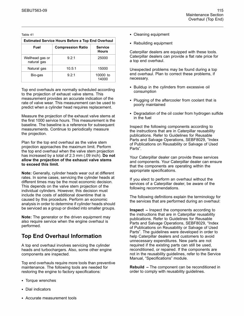
SEBU7563-09 115Maintenance SectionOverhaul (Top End)
Table 41
Estimated Service Hours Before a Top End Overhaul
Fuel Compression Ratio ServiceHours
Wellhead gas ornatural gas
9.2:1 25000
Natural gas 10.5:1 15000
Bio-gas 9.2:1 10000 to14000
Top end overhauls are normally scheduled accordingto the projection of exhaust valve stems. Thismeasurement provides an accurate indication of therate of valve wear. This measurement can be used topredict when a cylinder head requires replacement.
Measure the projection of the exhaust valve stems atthe first 1000 service hours. This measurement is thebaseline. The baseline is a reference for subsequentmeasurements. Continue to periodically measurethe projection.
Plan for the top end overhaul as the valve stemprojection approaches the maximum limit. Performthe top end overhaul when the valve stem projectionhas increased by a total of 2.3 mm (.09 inch). Do notallow the projection of the exhaust valve stemsto exceed this limit.
Note: Generally, cylinder heads wear out at differentrates. In some cases, servicing the cylinder heads atdifferent times may be the most economic decision.This depends on the valve stem projection of theindividual cylinders. However, this decision mustinclude the costs of additional downtime that iscaused by this procedure. Perform an economicanalysis in order to determine if cylinder heads shouldbe serviced as a group or divided into smaller groups.
Note: The generator or the driven equipment mayalso require service when the engine overhaul isperformed.
Top End Overhaul InformationA top end overhaul involves servicing the cylinderheads and turbochargers. Also, some other enginecomponents are inspected.
Top end overhauls require more tools than preventivemaintenance. The following tools are needed forrestoring the engine to factory specifications:
• Torque wrenches
• Dial indicators
• Accurate measurement tools
• Cleaning equipment
• Rebuilding equipment
Caterpillar dealers are equipped with these tools.Caterpillar dealers can provide a flat rate price fora top end overhaul.
Unexpected problems may be found during a topend overhaul. Plan to correct these problems, ifnecessary.
• Buildup in the cylinders from excessive oilconsumption
• Plugging of the aftercooler from coolant that ispoorly maintained
• Degradation of the oil cooler from hydrogen sulfidein the fuel
Inspect the following components according tothe instructions that are in Caterpillar reusabilitypublications. Refer to Guidelines for ReusableParts and Salvage Operations, SEBF8029, “Indexof Publications on Reusability or Salvage of UsedParts”.
Your Caterpillar dealer can provide these servicesand components. Your Caterpillar dealer can ensurethat the components are operating within theappropriate specifications.
If you elect to perform an overhaul without theservices of a Caterpillar dealer, be aware of thefollowing recommendations.
The following definitions explain the terminology forthe services that are performed during an overhaul:
Inspect – Inspect the components according tothe instructions that are in Caterpillar reusabilitypublications. Refer to Guidelines for ReusableParts and Salvage Operations, SEBF8029, “Indexof Publications on Reusability or Salvage of UsedParts”. The guidelines were developed in order tohelp Caterpillar dealers and customers to avoidunnecessary expenditures. New parts are notrequired if the existing parts can still be used,reconditioned, or repaired. If the components arenot in the reusability guidelines, refer to the ServiceManual, “Specifications” module.
Rebuild – The component can be reconditioned inorder to comply with reusability guidelines.
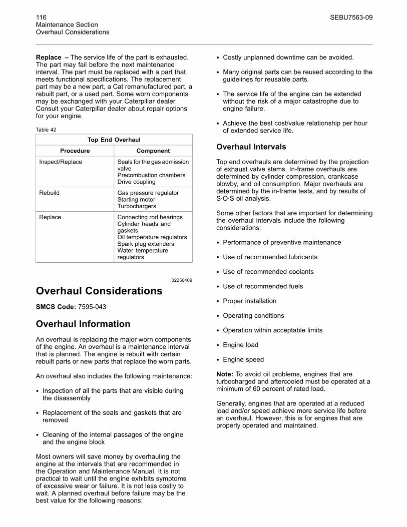
116 SEBU7563-09Maintenance SectionOverhaul Considerations
Replace – The service life of the part is exhausted.The part may fail before the next maintenanceinterval. The part must be replaced with a part thatmeets functional specifications. The replacementpart may be a new part, a Cat remanufactured part, arebuilt part, or a used part. Some worn componentsmay be exchanged with your Caterpillar dealer.Consult your Caterpillar dealer about repair optionsfor your engine.
Table 42
Top End Overhaul
Procedure Component
Inspect/Replace Seals for the gas admissionvalvePrecombustion chambersDrive coupling
Rebuild Gas pressure regulatorStarting motorTurbochargers
Replace Connecting rod bearingsCylinder heads andgasketsOil temperature regulatorsSpark plug extendersWater temperatureregulators
i02250409
Overhaul ConsiderationsSMCS Code: 7595-043
Overhaul InformationAn overhaul is replacing the major worn componentsof the engine. An overhaul is a maintenance intervalthat is planned. The engine is rebuilt with certainrebuilt parts or new parts that replace the worn parts.
An overhaul also includes the following maintenance:
• Inspection of all the parts that are visible duringthe disassembly
• Replacement of the seals and gaskets that areremoved
• Cleaning of the internal passages of the engineand the engine block
Most owners will save money by overhauling theengine at the intervals that are recommended inthe Operation and Maintenance Manual. It is notpractical to wait until the engine exhibits symptomsof excessive wear or failure. It is not less costly towait. A planned overhaul before failure may be thebest value for the following reasons:
• Costly unplanned downtime can be avoided.
• Many original parts can be reused according to theguidelines for reusable parts.
• The service life of the engine can be extendedwithout the risk of a major catastrophe due toengine failure.
• Achieve the best cost/value relationship per hourof extended service life.
Overhaul Intervals
Top end overhauls are determined by the projectionof exhaust valve stems. In-frame overhauls aredetermined by cylinder compression, crankcaseblowby, and oil consumption. Major overhauls aredetermined by the in-frame tests, and by results ofS·O·S oil analysis.
Some other factors that are important for determiningthe overhaul intervals include the followingconsiderations:
• Performance of preventive maintenance
• Use of recommended lubricants
• Use of recommended coolants
• Use of recommended fuels
• Proper installation
• Operating conditions
• Operation within acceptable limits
• Engine load
• Engine speed
Note: To avoid oil problems, engines that areturbocharged and aftercooled must be operated at aminimum of 60 percent of rated load.
Generally, engines that are operated at a reducedload and/or speed achieve more service life beforean overhaul. However, this is for engines that areproperly operated and maintained.
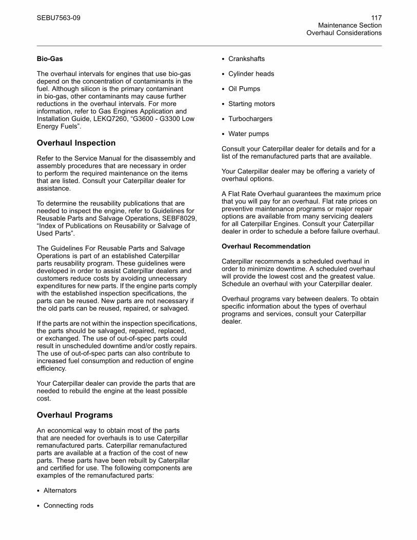
SEBU7563-09 117Maintenance Section
Overhaul Considerations
Bio-Gas
The overhaul intervals for engines that use bio-gasdepend on the concentration of contaminants in thefuel. Although silicon is the primary contaminantin bio-gas, other contaminants may cause furtherreductions in the overhaul intervals. For moreinformation, refer to Gas Engines Application andInstallation Guide, LEKQ7260, “G3600 - G3300 LowEnergy Fuels”.
Overhaul Inspection
Refer to the Service Manual for the disassembly andassembly procedures that are necessary in orderto perform the required maintenance on the itemsthat are listed. Consult your Caterpillar dealer forassistance.
To determine the reusability publications that areneeded to inspect the engine, refer to Guidelines forReusable Parts and Salvage Operations, SEBF8029,“Index of Publications on Reusability or Salvage ofUsed Parts”.
The Guidelines For Reusable Parts and SalvageOperations is part of an established Caterpillarparts reusability program. These guidelines weredeveloped in order to assist Caterpillar dealers andcustomers reduce costs by avoiding unnecessaryexpenditures for new parts. If the engine parts complywith the established inspection specifications, theparts can be reused. New parts are not necessary ifthe old parts can be reused, repaired, or salvaged.
If the parts are not within the inspection specifications,the parts should be salvaged, repaired, replaced,or exchanged. The use of out-of-spec parts couldresult in unscheduled downtime and/or costly repairs.The use of out-of-spec parts can also contribute toincreased fuel consumption and reduction of engineefficiency.
Your Caterpillar dealer can provide the parts that areneeded to rebuild the engine at the least possiblecost.
Overhaul Programs
An economical way to obtain most of the partsthat are needed for overhauls is to use Caterpillarremanufactured parts. Caterpillar remanufacturedparts are available at a fraction of the cost of newparts. These parts have been rebuilt by Caterpillarand certified for use. The following components areexamples of the remanufactured parts:
• Alternators
• Connecting rods
• Crankshafts
• Cylinder heads
• Oil Pumps
• Starting motors
• Turbochargers
• Water pumps
Consult your Caterpillar dealer for details and for alist of the remanufactured parts that are available.
Your Caterpillar dealer may be offering a variety ofoverhaul options.
A Flat Rate Overhaul guarantees the maximum pricethat you will pay for an overhaul. Flat rate prices onpreventive maintenance programs or major repairoptions are available from many servicing dealersfor all Caterpillar Engines. Consult your Caterpillardealer in order to schedule a before failure overhaul.
Overhaul Recommendation
Caterpillar recommends a scheduled overhaul inorder to minimize downtime. A scheduled overhaulwill provide the lowest cost and the greatest value.Schedule an overhaul with your Caterpillar dealer.
Overhaul programs vary between dealers. To obtainspecific information about the types of overhaulprograms and services, consult your Caterpillardealer.
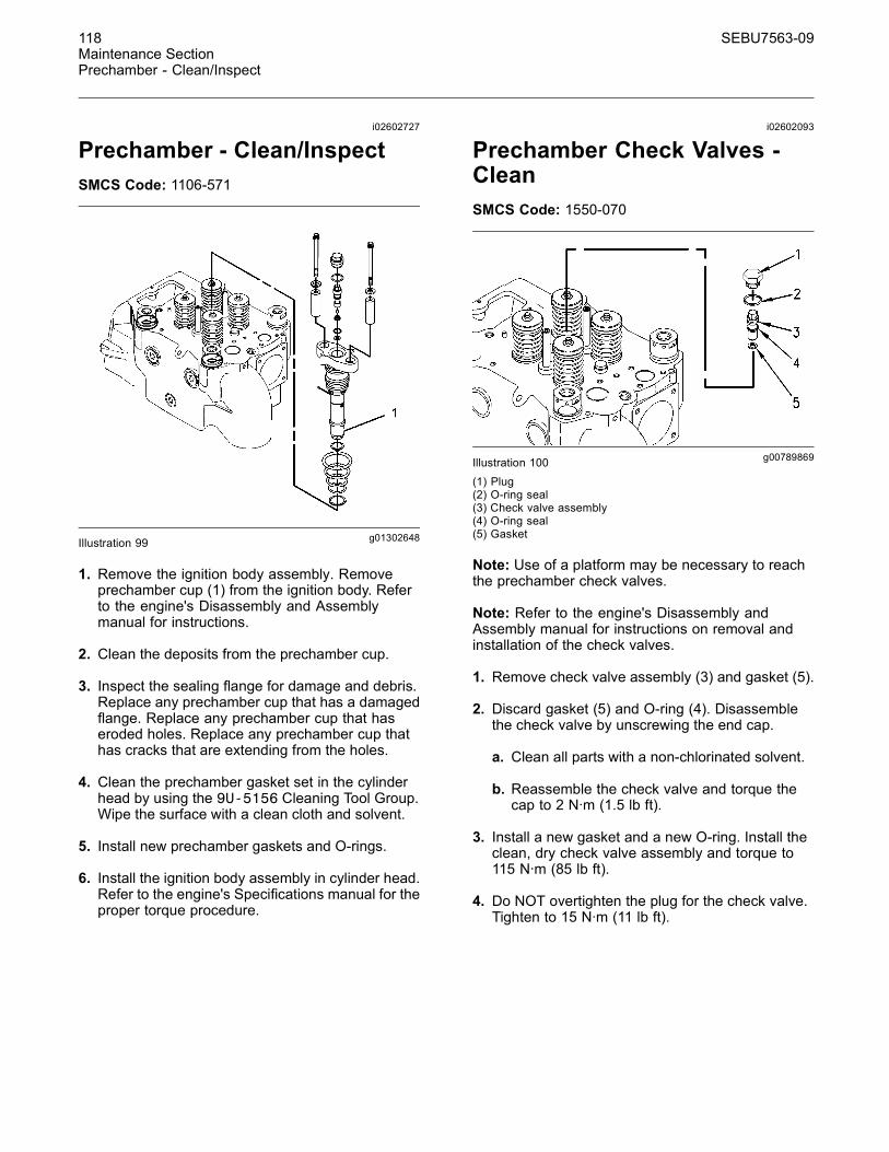
118 SEBU7563-09Maintenance SectionPrechamber - Clean/Inspect
i02602727
Prechamber - Clean/InspectSMCS Code: 1106-571
g01302648Illustration 99
1. Remove the ignition body assembly. Removeprechamber cup (1) from the ignition body. Referto the engine's Disassembly and Assemblymanual for instructions.
2. Clean the deposits from the prechamber cup.
3. Inspect the sealing flange for damage and debris.Replace any prechamber cup that has a damagedflange. Replace any prechamber cup that haseroded holes. Replace any prechamber cup thathas cracks that are extending from the holes.
4. Clean the prechamber gasket set in the cylinderhead by using the 9U-5156 Cleaning Tool Group.Wipe the surface with a clean cloth and solvent.
5. Install new prechamber gaskets and O-rings.
6. Install the ignition body assembly in cylinder head.Refer to the engine's Specifications manual for theproper torque procedure.
i02602093
Prechamber Check Valves -CleanSMCS Code: 1550-070
g00789869Illustration 100(1) Plug(2) O-ring seal(3) Check valve assembly(4) O-ring seal(5) Gasket
Note: Use of a platform may be necessary to reachthe prechamber check valves.
Note: Refer to the engine's Disassembly andAssembly manual for instructions on removal andinstallation of the check valves.
1. Remove check valve assembly (3) and gasket (5).
2. Discard gasket (5) and O-ring (4). Disassemblethe check valve by unscrewing the end cap.
a. Clean all parts with a non-chlorinated solvent.
b. Reassemble the check valve and torque thecap to 2 N·m (1.5 lb ft).
3. Install a new gasket and a new O-ring. Install theclean, dry check valve assembly and torque to115 N·m (85 lb ft).
4. Do NOT overtighten the plug for the check valve.Tighten to 15 N·m (11 lb ft).
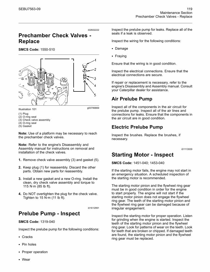
SEBU7563-09 119Maintenance Section
Prechamber Check Valves - Replace
i02602222
Prechamber Check Valves -ReplaceSMCS Code: 1550-510
g00789869Illustration 101(1) Plug(2) O-ring seal(3) Check valve assembly(4) O-ring seal(5) Gasket
Note: Use of a platform may be necessary to reachthe prechamber check valves.
Note: Refer to the engine's Disassembly andAssembly manual for instructions on removal andinstallation of the check valves.
1. Remove check valve assembly (3) and gasket (5).
2. Keep plug (1) for reassembly. Discard the otherparts. Obtain new parts for reassembly.
3. Install a new gasket and a new O-ring. Install theclean, dry check valve assembly and torque to115 N·m (85 lb ft).
4. Do NOT overtighten the plug for the check valve.Tighten to 15 N·m (11 lb ft).
i01612991
Prelube Pump - InspectSMCS Code: 1319-040
Inspect the prelube pump for the following conditions:
• Cracks
• Pin holes
• Proper operation
• Wear
Inspect the prelube pump for leaks. Replace all of theseals if a leak is observed.
Inspect the wiring for the following conditions:
• Damage
• Fraying
Ensure that the wiring is in good condition.
Inspect the electrical connections. Ensure that theelectrical connections are secure.
If repair or replacement is necessary, refer to theengine's Disassembly and Assembly manual. Consultyour Caterpillar dealer for assistance.
Air Prelube PumpInspect all of the components in the air circuit forthe prelube pump. Inspect all of the air lines andconnections for leaks. Ensure that the components inthe air circuit are in good condition.
Electric Prelube PumpInspect the brushes. Replace the brushes, ifnecessary.
i01113939
Starting Motor - InspectSMCS Code: 1451-040; 1453-040
If the starting motor fails, the engine may not start inan emergency situation. A scheduled inspection ofthe starting motor is recommended.
The starting motor pinion and the flywheel ring gearmust be in good condition in order for the engineto start properly. The engine will not start if thestarting motor pinion does not engage the flywheelring gear. The teeth of the starting motor pinion andthe flywheel ring gear can be damaged because ofirregular engagement.
Inspect the starting motor for proper operation. Listenfor grinding when the engine is started. Inspect theteeth of the starting motor pinion and the flywheelring gear. Look for patterns of wear on the teeth. Lookfor teeth that are broken or chipped. If damaged teethare found, the starting motor pinion and the flywheelring gear must be replaced.
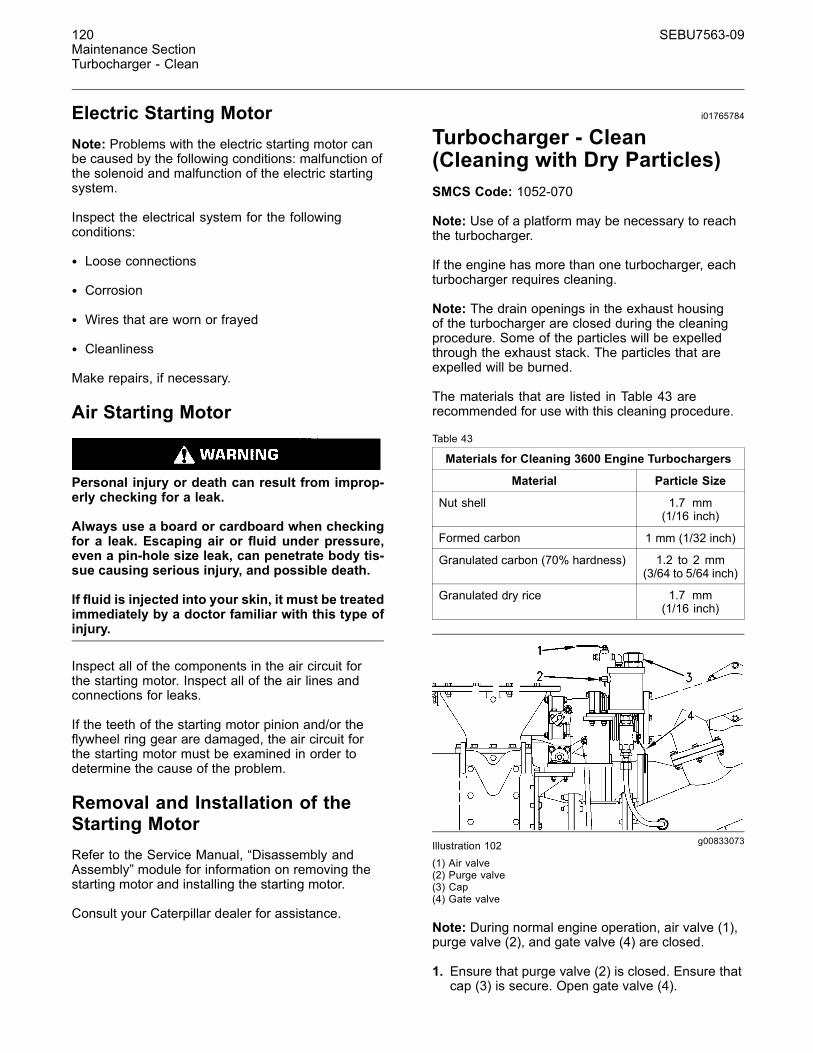
120 SEBU7563-09Maintenance SectionTurbocharger - Clean
Electric Starting MotorNote: Problems with the electric starting motor canbe caused by the following conditions: malfunction ofthe solenoid and malfunction of the electric startingsystem.
Inspect the electrical system for the followingconditions:
• Loose connections
• Corrosion
• Wires that are worn or frayed
• Cleanliness
Make repairs, if necessary.
Air Starting Motor
Personal injury or death can result from improp-erly checking for a leak.
Always use a board or cardboard when checkingfor a leak. Escaping air or fluid under pressure,even a pin-hole size leak, can penetrate body tis-sue causing serious injury, and possible death.
If fluid is injected into your skin, it must be treatedimmediately by a doctor familiar with this type ofinjury.
Inspect all of the components in the air circuit forthe starting motor. Inspect all of the air lines andconnections for leaks.
If the teeth of the starting motor pinion and/or theflywheel ring gear are damaged, the air circuit forthe starting motor must be examined in order todetermine the cause of the problem.
Removal and Installation of theStarting MotorRefer to the Service Manual, “Disassembly andAssembly” module for information on removing thestarting motor and installing the starting motor.
Consult your Caterpillar dealer for assistance.
i01765784
Turbocharger - Clean(Cleaning with Dry Particles)SMCS Code: 1052-070
Note: Use of a platform may be necessary to reachthe turbocharger.
If the engine has more than one turbocharger, eachturbocharger requires cleaning.
Note: The drain openings in the exhaust housingof the turbocharger are closed during the cleaningprocedure. Some of the particles will be expelledthrough the exhaust stack. The particles that areexpelled will be burned.
The materials that are listed in Table 43 arerecommended for use with this cleaning procedure.
Table 43
Materials for Cleaning 3600 Engine Turbochargers
Material Particle Size
Nut shell 1.7 mm(1/16 inch)
Formed carbon 1 mm (1/32 inch)
Granulated carbon (70% hardness) 1.2 to 2 mm(3/64 to 5/64 inch)
Granulated dry rice 1.7 mm(1/16 inch)
g00833073Illustration 102(1) Air valve(2) Purge valve(3) Cap(4) Gate valve
Note: During normal engine operation, air valve (1),purge valve (2), and gate valve (4) are closed.
1. Ensure that purge valve (2) is closed. Ensure thatcap (3) is secure. Open gate valve (4).
SEBU7563-09 121Maintenance Section
Turbocharger - Inspect
2. Open air valve (1) in order to remove depositsthat may be in the connecting pipe. After threeminutes, close air valve (1). Close gate valve (4).
3. Open purge valve (2) in order to relieve anypressure from the container. Close purge valve(2).
4. Remove cap (3). Pour 0.5 L (0.5 qt) of the particlesinto the container. Tighten cap (3).
5. Ensure that purge valve (2) is closed. Reducethe output of the engine so that the exhausttemperature before the turbine is less than 577 °C(1070 °F).
6. Open gate valve (4). Open air valve (1).
7. After 60 to 90 seconds, close air valve (1). Closegate valve (4).
8. Open purge valve (2) in order to relieve anypressure from the container. Close purge valve(2).
i00908991
Turbocharger - InspectSMCS Code: 1052-040
Periodic inspection and cleaning is recommendedfor the turbocharger.
Fouling of the turbine wheels can contribute to loss ofengine power and overall loss of engine efficiency.
If the turbocharger fails during engine operation,damage to the turbocharger compressor wheeland/or to the engine may occur. Damage to theturbocharger compressor wheel could allow partsfrom the compressor wheel to enter an enginecylinder. This can cause additional damage to thepistons, the valves, and the cylinder head.
NOTICETurbocharger bearing failures can cause large quan-tities of oil to enter the air inlet and exhaust systems.Loss of engine lubricant can result in serious enginedamage.
Minor leakage of a turbocharger housing under ex-tended low idle operation should not cause problemsas long as a turbocharger bearing failure has not oc-curred.
When a turbocharger bearing failure is accompaniedby a significant engine performance loss (exhaustsmoke or engine rpm up at no load), do not continueengine operation until the turbocharger is repaired orreplaced.
An inspection of the turbocharger can minimizeunscheduled downtime. An inspection of theturbocharger can also reduce the chance for potentialdamage to other engine parts.
Note: Turbocharger components require clearancesthat are precise. The turbocharger cartridge must bebalanced due to high rpm.
The following conditions can cause the turbochargerto be out-of-balance:
• The buildup of deposits
• Chipping and/or flaking of deposits
If the turbocharger must be removed for inspection,use caution. Do not break deposits from the turbinewheel. Do not attempt to clean the turbine wheel. Foroptions regarding removal, installation, repair andreplacement, see the Service Manual or consult yourCaterpillar dealer.
1. Remove the exhaust outlet piping and removethe air inlet piping from the turbocharger. Visuallyinspect the piping for the presence of oil.
2. Turn the compressor wheel and the turbine wheelby hand. The assembly should turn freely. Inspectthe compressor wheel and the turbine wheel forcontact with the turbocharger housing. Thereshould not be any visible signs of contact betweenthe turbine wheel or compressor wheel and theturbocharger housing. If there is any indication ofcontact between the rotating turbine wheel or thecompressor wheel and the turbocharger housing,the turbocharger must be reconditioned.
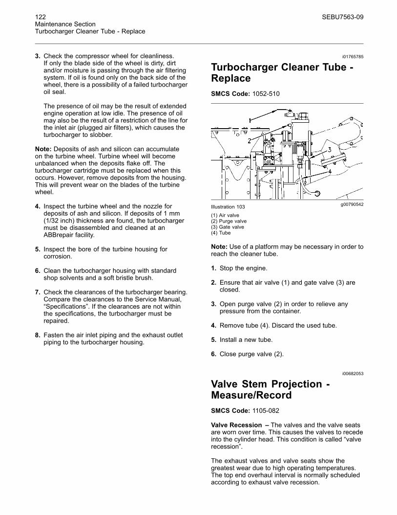
122 SEBU7563-09Maintenance SectionTurbocharger Cleaner Tube - Replace
3. Check the compressor wheel for cleanliness.If only the blade side of the wheel is dirty, dirtand/or moisture is passing through the air filteringsystem. If oil is found only on the back side of thewheel, there is a possibility of a failed turbochargeroil seal.
The presence of oil may be the result of extendedengine operation at low idle. The presence of oilmay also be the result of a restriction of the line forthe inlet air (plugged air filters), which causes theturbocharger to slobber.
Note: Deposits of ash and silicon can accumulateon the turbine wheel. Turbine wheel will becomeunbalanced when the deposits flake off. Theturbocharger cartridge must be replaced when thisoccurs. However, remove deposits from the housing.This will prevent wear on the blades of the turbinewheel.
4. Inspect the turbine wheel and the nozzle fordeposits of ash and silicon. If deposits of 1 mm(1/32 inch) thickness are found, the turbochargermust be disassembled and cleaned at anABBrepair facility.
5. Inspect the bore of the turbine housing forcorrosion.
6. Clean the turbocharger housing with standardshop solvents and a soft bristle brush.
7. Check the clearances of the turbocharger bearing.Compare the clearances to the Service Manual,“Specifications”. If the clearances are not withinthe specifications, the turbocharger must berepaired.
8. Fasten the air inlet piping and the exhaust outletpiping to the turbocharger housing.
i01765785
Turbocharger Cleaner Tube -ReplaceSMCS Code: 1052-510
g00790542Illustration 103(1) Air valve(2) Purge valve(3) Gate valve(4) Tube
Note: Use of a platform may be necessary in order toreach the cleaner tube.
1. Stop the engine.
2. Ensure that air valve (1) and gate valve (3) areclosed.
3. Open purge valve (2) in order to relieve anypressure from the container.
4. Remove tube (4). Discard the used tube.
5. Install a new tube.
6. Close purge valve (2).
i00682053
Valve Stem Projection -Measure/RecordSMCS Code: 1105-082
Valve Recession – The valves and the valve seatsare worn over time. This causes the valves to recedeinto the cylinder head. This condition is called “valverecession”.
The exhaust valves and valve seats show thegreatest wear due to high operating temperatures.The top end overhaul interval is normally scheduledaccording to exhaust valve recession.
SEBU7563-09 123Maintenance Section
Walk-Around Inspection
The actual measurement of the valve recessioninside of the cylinder head is difficult to obtain.Two simpler methods are used to determine valverecession:
• Measure the projection of the valve stem abovethe cylinder head. It is necessary to remove therocker arms in order to obtain this measurement.This method is more accurate than measuring theprojection of the exhaust valve rotators. Measurethe projection of the exhaust valve stems with the4C-2980 Cylinder Head Valve Projection Group.
• Measure the projection of the valve rotator abovethe cylinder head. It is not necessary to remove therocker arms in order to obtain this measurement.Measure the projection of the exhaust valverotators with the 148-2997 Valve Recession ToolGroup.
Make several copies of this Operation andMaintenance Manual, “Valve Data Sheet” (ReferenceMaterials Section). Record the measurements onthe sheets.
• Measure the projection of the inlet and exhaustvalve stems and the exhaust valve rotators atthe first 1000 service hours. This measurementis the baseline. The baseline is a reference forsubsequent measurements.
• Measure the projection of the inlet and exhaustvalve rotators when the engine valve lash ischecked. Continue this periodic measurement untilthe projection of the valve rotator has increased bya total of 1.6 mm (.063 inch). This is 70 percent ofthe maximum limit. Measure the projection of thevalve stems when this occurs. This measurementwill determine the actual wear of both the valvesand the valve seats.
• After 70 percent of the maximum limit has beenreached, measure the projection of the exhaustvalve stems at every 500 hours of operation.
• Plan for the top end overhaul as the valvestem projection approaches the maximum limit.Perform the top end overhaul when the valve stemprojection has increased by a total of 2.3 mm(.09 inch). Do not allow the valve recessionto exceed this limit. The valve head can break.This will cause severe damage in the combustionchamber and the turbocharger.
Consult your Caterpillar dealer for assistance.
i01492446
Walk-Around InspectionSMCS Code: 1000-040
Inspect the Engine for Leaks andfor Loose ConnectionsA walk-around inspection should only take a fewminutes. When the time is taken to perform thesechecks, costly repairs and accidents can be avoided.
For maximum engine service life, thoroughly inspectthe engine room before starting the engine. Look foritems such as leaks, loose bolts, loose connectionsand trash buildup. Make repairs, as needed.
• The guards must be in the proper place. Repairdamaged guards or replace missing guards.
• Wipe all caps and plugs before the engine isserviced in order to reduce the chance of systemcontamination.
NOTICEFor any type of leak, clean up the fluid. If leaking is ob-served, find the source and correct the leak. If leakingis suspected, check the fluid levels more often thanrecommended until the leak is found or fixed, or untilthe suspicion of a leak is proved to be unwarranted.
NOTICEAccumulated grease and/or oil on an engine or deck isa fire hazard. Remove this debris with steam cleaningor high pressure water.
• Ensure that cooling lines are properly clamped.Check for leaks. Check the condition of all pipes.
• Inspect the water pumps for coolant leaks.
Note: The water pump seal is lubricated by coolantin the cooling system. It is normal for a small amountof leakage to occur when the engine cools and theparts contract.
Excessive coolant leakage may indicate the needto replace the water pump seal. For instructionson removal and installation of water pumps and/orseals, refer to the Service Manual, “Disassembly andAssembly” module for the engine or consult yourCaterpillar dealer.
• Inspect the lubrication system for leaks at the frontcrankshaft seal, the rear crankshaft seal, the oilpan, the oil filters and the valve covers.
124 SEBU7563-09Maintenance SectionWater Pump - Inspect
NEVER use a flame to check for gas leaks. Use agas detector.
An open flame can ignite mixtures of air and fuel.This will cause explosion and/or fire which couldresult in severe personal injury or death.
• Check the fuel system for leaks. Look for loose fuelline clamps.
• Inspect the piping for the air inlet system and theelbows for cracks and for loose clamps.
• Inspect the wiring and the wiring harnesses forloose connections and for worn wires or frayedwires.
• Inspect the ground straps for good connectionsand for good condition.
• Check the condition of the gauges. Replace anygauge that is damaged. Replace any gauge thatcan not be calibrated.
• Inspect the exhaust system for leaks. If a leak isfound, make repairs.
i02624237
Water Pump - InspectSMCS Code: 1361-040
A failed water pump might cause severe engineoverheating problems that could result in cracks inthe cylinder head, a piston seizure or other potentialdamage to the engine.
Visually inspect the water pump for leaks. If leakingof the water pump seals is observed, replace all ofthe water pump seals. Refer to two articles in theDisassembly and Assembly Manual, “Water Pump- Disassemble and Water Pump - Assemble” forthe disassembly and assembly procedure. If it isnecessary to remove the water pump, refer to twoarticles in the Disassembly and Assembly Manual,“Water Pump - Remove and Water Pump - Install”.
Inspect the water pump for wear, cracks, pin holesand proper operation. Refer to the Parts Manualfor the correct part numbers for your engine orconsult your Caterpillar dealer if repair is needed orreplacement is needed.