catia v5 workbook - sdc publications · pdf filecatia v5 workbook releases 8 & 9 by:...
TRANSCRIPT
CATIA V5 Workbook Releases 8 & 9
By:
Richard Cozzens
Southern Utah University
SDC
Schroff Development Corporation
www.schroff.com
www.schroff-europe.com
PUBLICATIONS
Lesson 1 Sketcher Work Bench
Introduction To The Sketcher Work Bench
This lesson will take you through each step in creating a simple sketch and ending with a
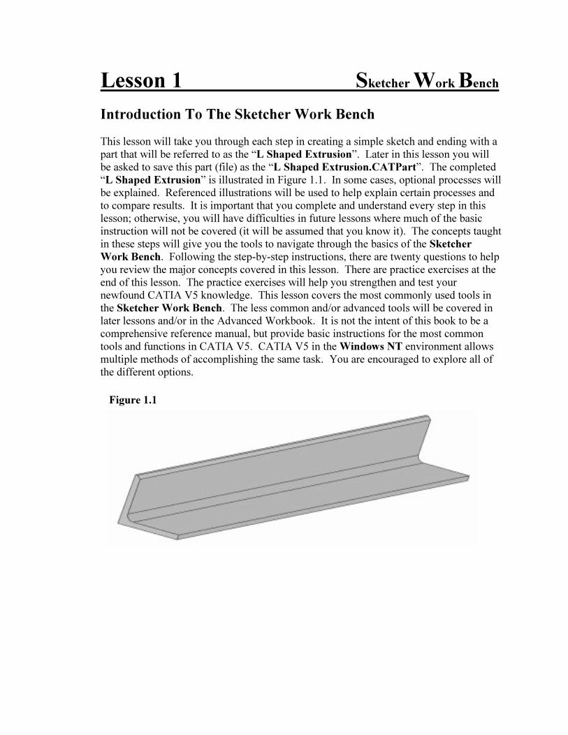
part that will be referred to as the “L Shaped Extrusion”. Later in this lesson you will
be asked to save this part (file) as the “L Shaped Extrusion.CATPart”. The completed
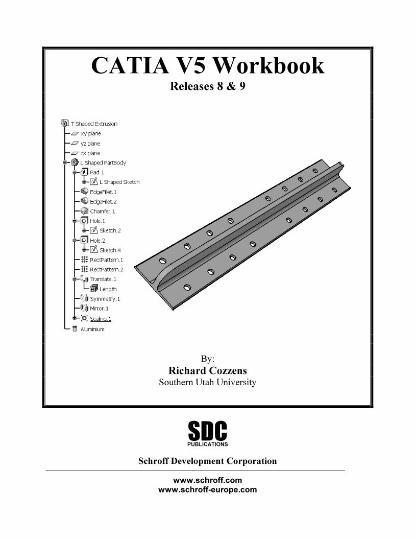
“L Shaped Extrusion” is illustrated in Figure 1.1. In some cases, optional processes will
be explained. Referenced illustrations will be used to help explain certain processes and
to compare results. It is important that you complete and understand every step in this
lesson; otherwise, you will have difficulties in future lessons where much of the basic
instruction will not be covered (it will be assumed that you know it). The concepts taught
in these steps will give you the tools to navigate through the basics of the Sketcher
Work Bench. Following the step-by-step instructions, there are twenty questions to help
you review the major concepts covered in this lesson. There are practice exercises at the
end of this lesson. The practice exercises will help you strengthen and test your
newfound CATIA V5 knowledge. This lesson covers the most commonly used tools in
the Sketcher Work Bench. The less common and/or advanced tools will be covered in
later lessons and/or in the Advanced Workbook. It is not the intent of this book to be a
comprehensive reference manual, but provide basic instructions for the most common
tools and functions in CATIA V5. CATIA V5 in the Windows NT environment allows
multiple methods of accomplishing the same task. You are encouraged to explore all of
the different options.
Figure 1.1
1.2 Sketcher Work Bench
Figure 1.2
Figure 1.3
Lesson 1 Objectives
This lesson will show you how to do the following:
- Start CATIA V5
- Select the a specific workbench
- Move around in the CATIA V5 Environment
- Select a working plane
- Enter the Sketcher Work Bench
- Basic customization of the Sketcher Work Bench
- Create a sketch using the standard sketch tools
- Apply Constraints to the sketch
- Modify existing Constraints
- Exit the Sketcher Work Bench
- Create a Pad in the Part Design Work Bench
- Save the newly create file
- Exit CATIA V5
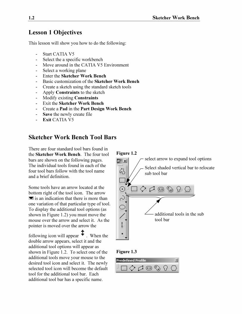
Sketcher Work Bench Tool Bars
There are four standard tool bars found in
the Sketcher Work Bench. The four tool
bars are shown on the following pages.
The individual tools found in each of the
four tool bars follow with the tool name
and a brief definition.
Some tools have an arrow located at the
bottom right of the tool icon. The arrow
is an indication that there is more than
one variation of that particular type of tool.
To display the additional tool options (as
shown in Figure 1.2) you must move the
mouse over the arrow and select it. As the
pointer is moved over the arrow the
following icon will appear . When the
double arrow appears, select it and the
additional tool options will appear as
shown in Figure 1.2. To select one of the
additional tools move your mouse to the
desired tool icon and select it. The newly
selected tool icon will become the default
tool for the additional tool bar. Each
additional tool bar has a specific name.
select arrow to expand tool options
additional tools in the sub
tool bar
Select shaded vertical bar to relocate
sub tool bar
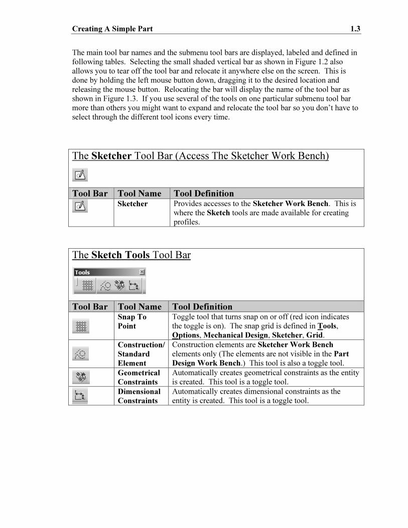
Creating A Simple Part 1.3
The main tool bar names and the submenu tool bars are displayed, labeled and defined in
following tables. Selecting the small shaded vertical bar as shown in Figure 1.2 also
allows you to tear off the tool bar and relocate it anywhere else on the screen. This is
done by holding the left mouse button down, dragging it to the desired location and
releasing the mouse button. Relocating the bar will display the name of the tool bar as
shown in Figure 1.3. If you use several of the tools on one particular submenu tool bar
more than others you might want to expand and relocate the tool bar so you don’t have to
select through the different tool icons every time.
The Sketcher Tool Bar (Access The Sketcher Work Bench)
Tool Bar Tool Name Tool Definition
Sketcher
Provides accesses to the Sketcher Work Bench. This is
where the Sketch tools are made available for creating
profiles.
The Sketch Tools Tool Bar
Tool Bar Tool Name Tool Definition
Snap To
Point
Toggle tool that turns snap on or off (red icon indicates
the toggle is on). The snap grid is defined in Tools,
Options, Mechanical Design, Sketcher, Grid.
Construction/
Standard
Element
Construction elements are Sketcher Work Bench
elements only (The elements are not visible in the Part
Design Work Bench.) This tool is also a toggle tool.
Geometrical
Constraints
Automatically creates geometrical constraints as the entity
is created. This tool is a toggle tool.
Dimensional
Constraints
Automatically creates dimensional constraints as the
entity is created. This tool is a toggle tool.
1.4 Sketcher Work Bench
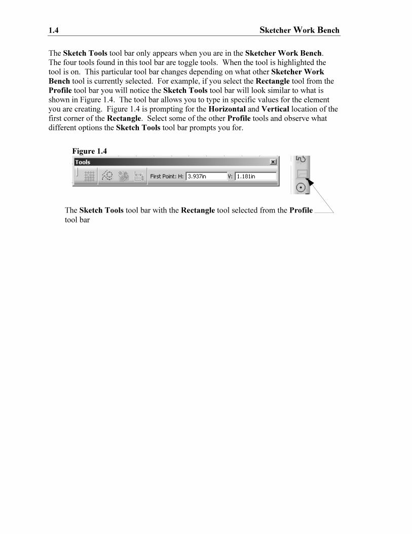
Figure 1.4
The Sketch Tools tool bar with the Rectangle tool selected from the Profile
tool bar
The Sketch Tools tool bar only appears when you are in the Sketcher Work Bench.
The four tools found in this tool bar are toggle tools. When the tool is highlighted the
tool is on. This particular tool bar changes depending on what other Sketcher Work
Bench tool is currently selected. For example, if you select the Rectangle tool from the
Profile tool bar you will notice the Sketch Tools tool bar will look similar to what is
shown in Figure 1.4. The tool bar allows you to type in specific values for the element
you are creating. Figure 1.4 is prompting for the Horizontal and Vertical location of the
first corner of the Rectangle. Select some of the other Profile tools and observe what
different options the Sketch Tools tool bar prompts you for.
Creating A Simple Part 1.5
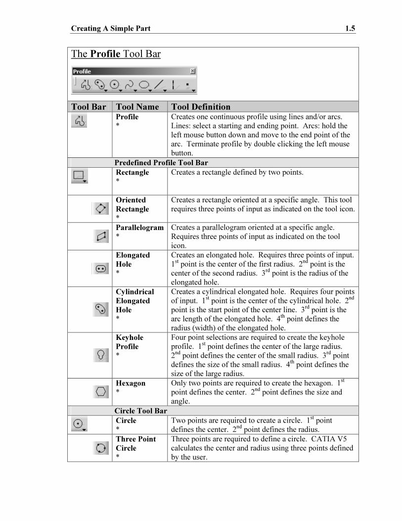
The Profile Tool Bar
Tool Bar Tool Name Tool Definition
Profile
*
Creates one continuous profile using lines and/or arcs.
Lines: select a starting and ending point. Arcs: hold the
left mouse button down and move to the end point of the
arc. Terminate profile by double clicking the left mouse
button.
Predefined Profile Tool Bar
Rectangle
*
Creates a rectangle defined by two points.
Oriented
Rectangle
*
Creates a rectangle oriented at a specific angle. This tool
requires three points of input as indicated on the tool icon.
Parallelogram
*
Creates a parallelogram oriented at a specific angle.
Requires three points of input as indicated on the tool
icon.
Elongated
Hole
*
Creates an elongated hole. Requires three points of input.
1st point is the center of the first radius. 2
nd point is the
center of the second radius. 3rd point is the radius of the
elongated hole.
Cylindrical
Elongated
Hole
*
Creates a cylindrical elongated hole. Requires four points
of input. 1st point is the center of the cylindrical hole. 2
nd
point is the start point of the center line. 3rd point is the
arc length of the elongated hole. 4th point defines the
radius (width) of the elongated hole.
Keyhole
Profile
*
Four point selections are required to create the keyhole
profile. 1st point defines the center of the large radius.
2nd point defines the center of the small radius. 3
rd point
defines the size of the small radius. 4th point defines the
size of the large radius.
Hexagon
*
Only two points are required to create the hexagon. 1st
point defines the center. 2nd point defines the size and
angle.
Circle Tool Bar
Circle
*
Two points are required to create a circle. 1st point
defines the center. 2nd point defines the radius.
Three Point
Circle
*
Three points are required to define a circle. CATIA V5
calculates the center and radius using three points defined
by the user.
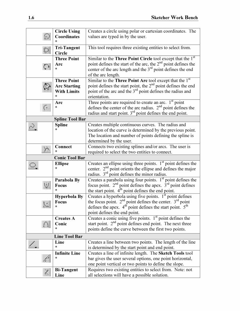
1.6 Sketcher Work Bench
Circle Using
Coordinates
*
Creates a circle using polar or cartesian coordinates. The
values are typed in by the user.
Tri-Tangent
Circle
This tool requires three existing entities to select from.
Three Point
Arc
*
Similar to the Three Point Circle tool except that the 1st
point defines the start of the arc, the 2nd point defines the
center of the arc length and the 3rd point defines the end
of the arc length. Three Point
Arc Starting
With Limits
*
Similar to the Three Point Arc tool except that the 1st
point defines the start point, the 2nd point defines the end
point of the arc and the 3rd point defines the radius and
orientation.
Arc
*
Three points are required to create an arc. 1st point
defines the center of the arc radius. 2nd point defines the
radius and start point. 3rd point defines the end point.
Spline Tool Bar
Spline
*
Creates multiple continuous curves. The radius and
location of the curve is determined by the previous point.
The location and number of points defining the spline is
determined by the user.
Connect
*
Connects two existing splines and/or arcs. The user is
required to select the two entities to connect.
Conic Tool Bar
Ellipse
*
Creates an ellipse using three points. 1st point defines the
center. 2nd point orients the ellipse and defines the major
radius. 3rd point defines the minor radius.
Parabola By
Focus
*
Creates a parabola using four points. 1st point defines the
focus point. 2nd point defines the apex. 3
rd point defines
the start point. 4th point defines the end point.
Hyperbola By
Focus
*
Creates a hyperbola using five points. 1st point defines
the focus point. 2nd point defines the center. 3
rd point
defines the apex. 4th point defines the start point. 5
th
point defines the end point.
Creates A
Conic
*
Creates a conic using five points. 1st point defines the
start point. 2nd point defines end point. The next three
points define the curve between the first two points.
Line Tool Bar
Line
*
Creates a line between two points. The length of the line
is determined by the start point and end point.
Infinite Line
*
Creates a line of infinite length. The Sketch Tools tool
bar gives the user several options, one point horizontal,
one point vertical or two points to define the slope.
Bi-Tangent
Line
Requires two existing entities to select from. Note: not
all selections will have a possible solution.
Creating A Simple Part 1.7
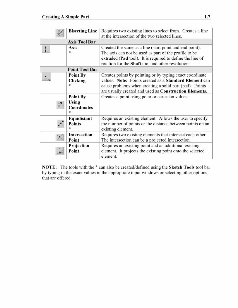
Bisecting Line
Requires two existing lines to select from. Creates a line
at the intersection of the two selected lines.
Axis Tool Bar
Axis
*
Created the same as a line (start point and end point).
The axis can not be used as part of the profile to be
extruded (Pad tool). It is required to define the line of
rotation for the Shaft tool and other revolutions.
Point Tool Bar
Point By
Clicking
*
Creates points by pointing or by typing exact coordinate
values. Note: Points created as a Standard Element can
cause problems when creating a solid part (pad). Points
are usually created and used as Construction Elements.
Point By
Using
Coordinates
*
Creates a point using polar or cartesian values.
Equidistant
Points
*
Requires an existing element. Allows the user to specify
the number of points or the distance between points on an
existing element.
Intersection
Point
Requires two existing elements that intersect each other.
The intersection can be a projected intersection.
Projection
Point
Requires an existing point and an additional existing
element. It projects the existing point onto the selected
element.
NOTE: The tools with the * can also be created/defined using the Sketch Tools tool bar
by typing in the exact values in the appropriate input windows or selecting other options
that are offered.
1.8 Sketcher Work Bench
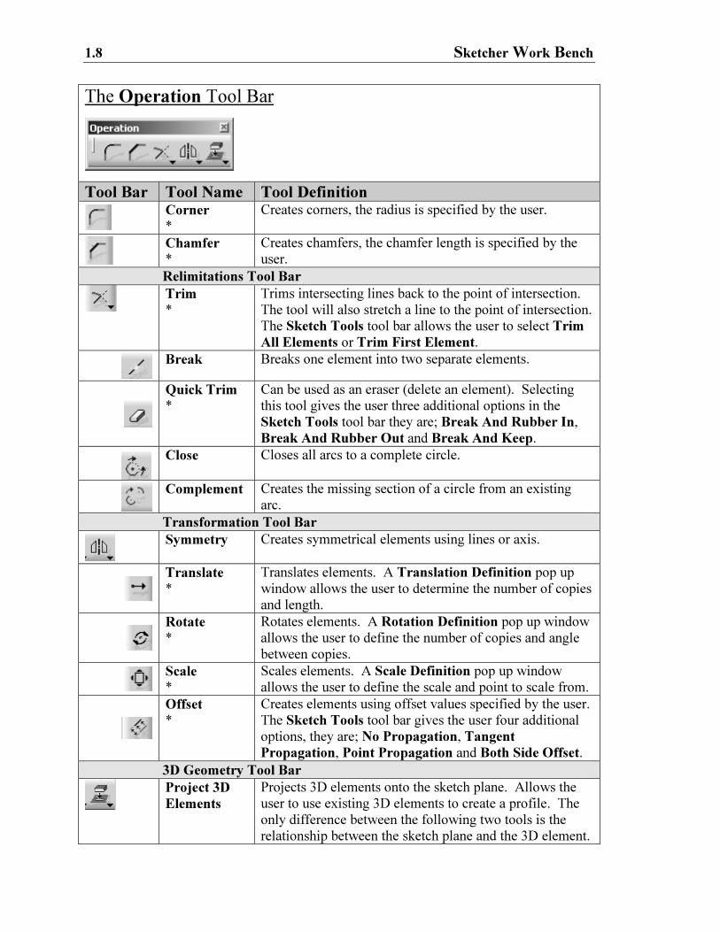
The Operation Tool Bar
Tool Bar Tool Name Tool Definition
Corner
*
Creates corners, the radius is specified by the user.
Chamfer
*
Creates chamfers, the chamfer length is specified by the
user.
Relimitations Tool Bar
Trim
*
Trims intersecting lines back to the point of intersection.
The tool will also stretch a line to the point of intersection.
The Sketch Tools tool bar allows the user to select Trim
All Elements or Trim First Element.
Break
Breaks one element into two separate elements.
Quick Trim
*
Can be used as an eraser (delete an element). Selecting
this tool gives the user three additional options in the
Sketch Tools tool bar they are; Break And Rubber In,
Break And Rubber Out and Break And Keep. Close
Closes all arcs to a complete circle.
Complement
Creates the missing section of a circle from an existing
arc.
Transformation Tool Bar
Symmetry
Creates symmetrical elements using lines or axis.
Translate
*
Translates elements. A Translation Definition pop up
window allows the user to determine the number of copies
and length.
Rotate
*
Rotates elements. A Rotation Definition pop up window
allows the user to define the number of copies and angle
between copies.
Scale
*
Scales elements. A Scale Definition pop up window
allows the user to define the scale and point to scale from.
Offset
*
Creates elements using offset values specified by the user.
The Sketch Tools tool bar gives the user four additional
options, they are; No Propagation, Tangent
Propagation, Point Propagation and Both Side Offset.
3D Geometry Tool Bar
Project 3D
Elements
Projects 3D elements onto the sketch plane. Allows the
user to use existing 3D elements to create a profile. The
only difference between the following two tools is the
relationship between the sketch plane and the 3D element.
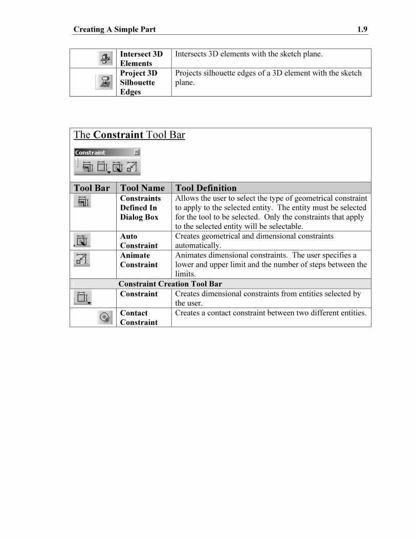
Creating A Simple Part 1.9
Intersect 3D
Elements
Intersects 3D elements with the sketch plane.
Project 3D
Silhouette
Edges
Projects silhouette edges of a 3D element with the sketch
plane.
The Constraint Tool Bar
Tool Bar Tool Name Tool Definition
Constraints
Defined In
Dialog Box
Allows the user to select the type of geometrical constraint
to apply to the selected entity. The entity must be selected
for the tool to be selected. Only the constraints that apply
to the selected entity will be selectable.
Auto
Constraint
Creates geometrical and dimensional constraints
automatically.
Animate
Constraint
Animates dimensional constraints. The user specifies a
lower and upper limit and the number of steps between the
limits.
Constraint Creation Tool Bar
Constraint
Creates dimensional constraints from entities selected by
the user.
Contact
Constraint
Creates a contact constraint between two different entities.
1.10 Sketcher Work Bench
Figure 1.5
When you are in the Sketcher Work Bench, the first tool bar (the Sketch Tools tool bar)
by default will appear floating in the upper left hand corner of the screen. The last three
tool bars (Profile, Operation and Constraint) are located by default on the right side of
the screen. The four tool bars contain too many tools to show all of them in one lesson.
To view and have access to all of the tools, you can select the shaded tab located at the
top of each tool bar and drag it anywhere on the screen. This is important, because when
you get to Step 12, by the default setup, you will not be able to visually locate the
Operation tool bar. You will have to select and drag the Operation tool bar from the
bottom right side of the screen to the location you select.
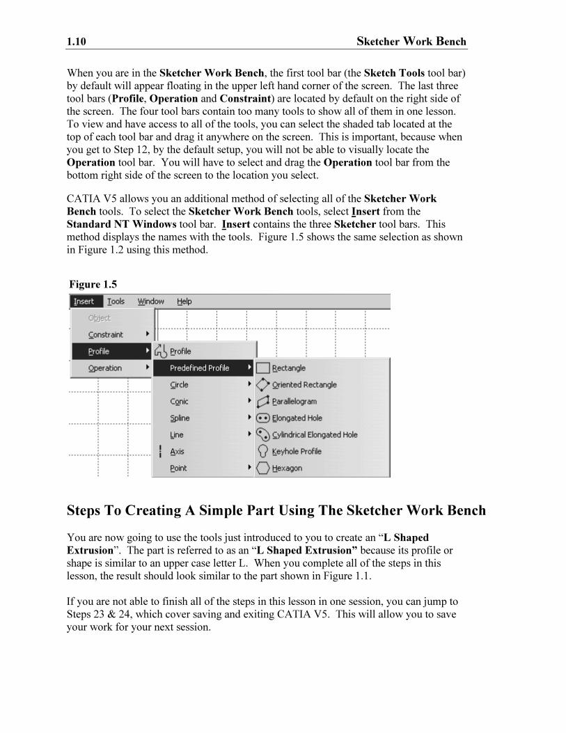
CATIA V5 allows you an additional method of selecting all of the Sketcher Work
Bench tools. To select the Sketcher Work Bench tools, select Insert from the
Standard NT Windows tool bar. Insert contains the three Sketcher tool bars. This
method displays the names with the tools. Figure 1.5 shows the same selection as shown
in Figure 1.2 using this method.
Steps To Creating A Simple Part Using The Sketcher Work Bench
You are now going to use the tools just introduced to you to create an “L Shaped
Extrusion”. The part is referred to as an “L Shaped Extrusion” because its profile or
shape is similar to an upper case letter L. When you complete all of the steps in this
lesson, the result should look similar to the part shown in Figure 1.1.
If you are not able to finish all of the steps in this lesson in one session, you can jump to
Steps 23 & 24, which cover saving and exiting CATIA V5. This will allow you to save
your work for your next session.
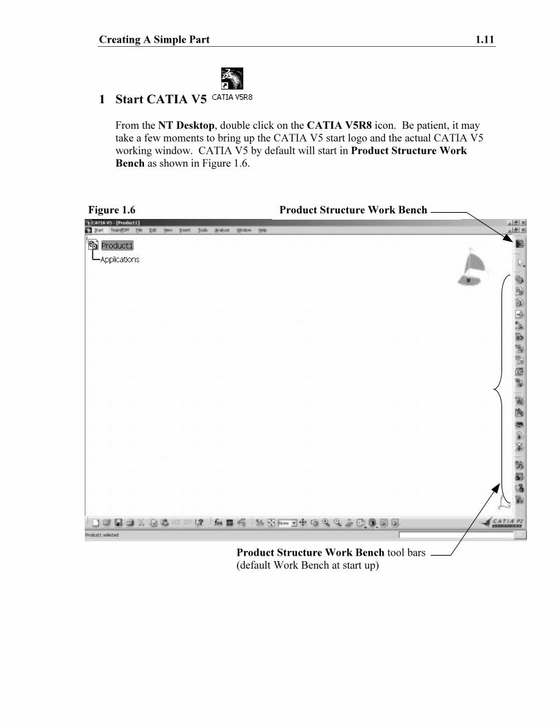
Creating A Simple Part 1.11
Figure 1.6 Product Structure Work Bench
Product Structure Work Bench tool bars
(default Work Bench at start up)
1 Start CATIA V5
From the NT Desktop, double click on the CATIA V5R8 icon. Be patient, it may
take a few moments to bring up the CATIA V5 start logo and the actual CATIA V5
working window. CATIA V5 by default will start in Product Structure Work
Bench as shown in Figure 1.6.
1.12 Sketcher Work Bench
Figure 1.7
2 Select The Sketcher Work Bench.
How your CATIA V5 screen looks at start up will depend on how it was setup and/or
customized. This step will cover most of the options you could encounter. The
CATIA V5 screen will appear as it does in Figure 1.6. The default work bench is the
Product Structure Work Bench. For this lesson, you will need to select the
Sketcher Work Bench.
There are two possible methods to selecting the Sketcher Work Bench.
2.1 The first method of selecting a work bench is using the Start menu located in the
Standard Windows tool bar. If you have not previously set up your favorite
work benches this step will only display the work benches under the CATIA V5
Functions. Step 2.3 explains how to create your favorite work benches.
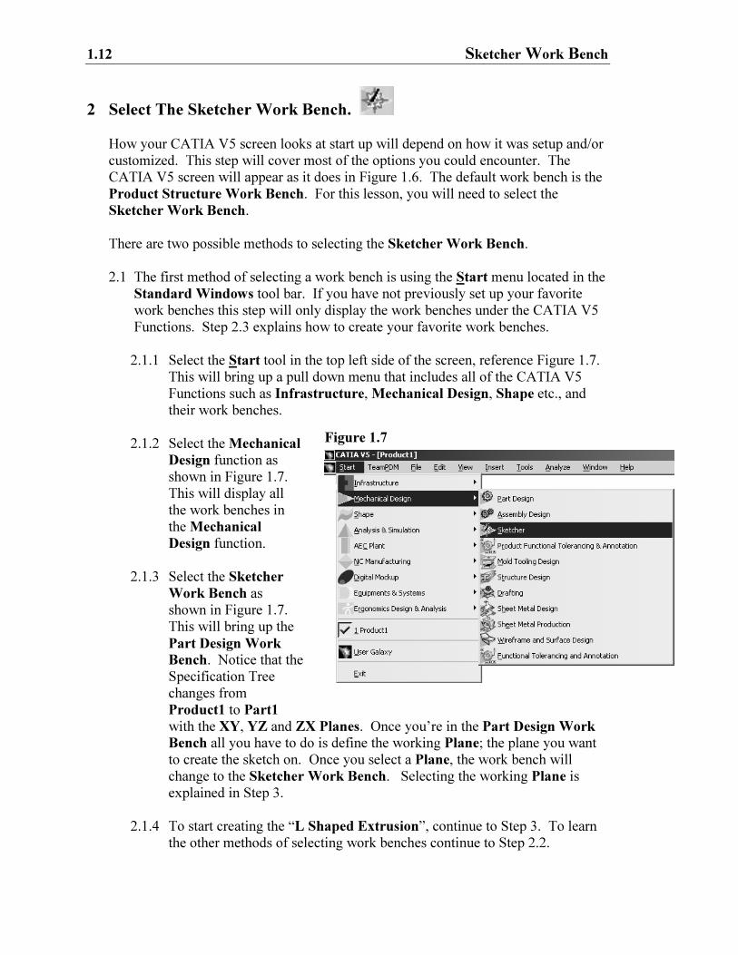
2.1.1 Select the Start tool in the top left side of the screen, reference Figure 1.7.
This will bring up a pull down menu that includes all of the CATIA V5
Functions such as Infrastructure, Mechanical Design, Shape etc., and
their work benches.
2.1.2 Select the Mechanical
Design function as
shown in Figure 1.7.
This will display all
the work benches in
the Mechanical
Design function.
2.1.3 Select the Sketcher
Work Bench as
shown in Figure 1.7.
This will bring up the
Part Design Work
Bench. Notice that the
Specification Tree
changes from
Product1 to Part1
with the XY, YZ and ZX Planes. Once you’re in the Part Design Work
Bench all you have to do is define the working Plane; the plane you want
to create the sketch on. Once you select a Plane, the work bench will
change to the Sketcher Work Bench. Selecting the working Plane is
explained in Step 3.
2.1.4 To start creating the “L Shaped Extrusion”, continue to Step 3. To learn
the other methods of selecting work benches continue to Step 2.2.
Creating A Simple Part 1.13
Figure 1.8
2.2 The work benches that appear in the Welcome To CATIA V5 window depend
on how CATIA V5 was installed. To find out which work benches were added
to the Welcome To CATIA V5 window, complete the following steps.
2.2.1 Select the Product Structure Work Bench in the top right of
your screen, reference Figure 1.9. Selecting the current work bench
will activate the Welcome To CATIA V5 window.
2.2.2 If there are no work benches displayed in the Welcome To CAITA
V5 window then nothing was added at installation. Figure 1.9 shows
three work benches, Step 2.3 shows you how to customize this
window.
2.3 To add your favorite work benches to the Welcome To CATIA V5 window
complete the following steps.
2.3.1 From the Standard Windows tool bar select Tools.
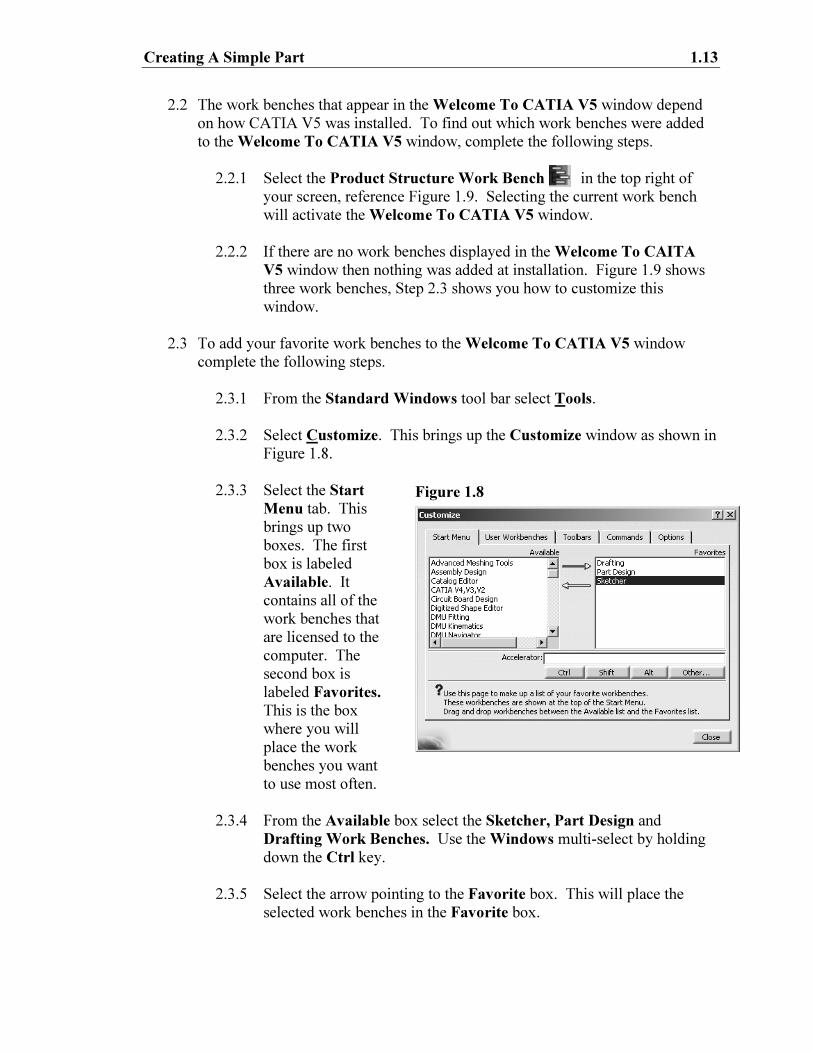
2.3.2 Select Customize. This brings up the Customize window as shown in
Figure 1.8.
2.3.3 Select the Start
Menu tab. This
brings up two
boxes. The first
box is labeled
Available. It
contains all of the
work benches that
are licensed to the
computer. The
second box is
labeled Favorites.
This is the box
where you will
place the work
benches you want
to use most often.
2.3.4 From the Available box select the Sketcher, Part Design and
Drafting Work Benches. Use the Windows multi-select by holding
down the Ctrl key.
2.3.5 Select the arrow pointing to the Favorite box. This will place the
selected work benches in the Favorite box.
1.14 Sketcher Work Bench
2.3.6 You can create an Accelerator (quick key) by selecting the
particular work bench and typing in the chosen Accelerator keys in
the Accelerator box. The keys must be separated by the “+” key.
For this step, create an Accelerator key for the Sketcher Work
Bench by completing the following steps.
2.3.6.1 Highlight the work bench in the Favorites box that you are
going to create the Accelerator key for.
2.3.6.2 With the correct work bench highlighted, place the cursor
in the Accelerator box.
2.3.6.3 Click on the Ctrl selection beneath the box.
2.3.6.4 Type in the character “+” with no spaces after the Ctrl.
2.3.6.5 Type in the small letter “k”, again with no spaces between
the characters.
2.3.6.6 Hit Enter. The Accelerator key is now created.
If you attempt to use Accelerator keys already assigned, a pop-up
window will warn you that it has already been assigned to a
particular function. This step has given you one more method of
selecting the Sketcher Work Bench.
2.3.7 Select the Close button. The Customize window will disappear.
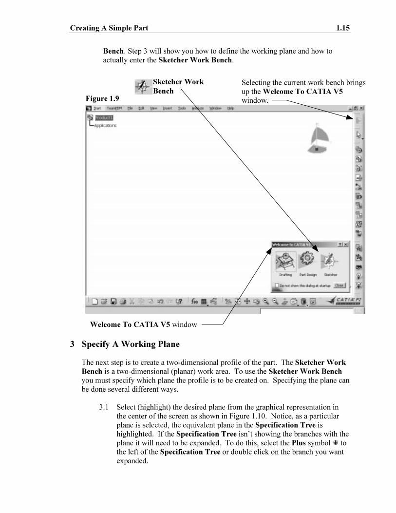
2.3.8 Select the current work bench as shown in Figure 1.9. This will
bring up the Welcome To CATIA V5 window. This time the
Sketcher, Part Design and Drafting Work Benches will be in the
Welcome To CATIA V5 window as shown in Figure 1.9.
2.3.9 You can also select the Start tool as shown in Step 2.1.1 and Figure
1.7. This time the three work benches added to the Welcome To
CATIA V5 window will appear in the CATIA Functions. The
work benches can be selected from this menu also.
2.4 Select the Sketcher Work Bench from the Start tool bar or the Welcome To
CATIA V5 window. This will bring up the Part Design Work Bench and all
of the Part Design tools. The reason it brings up the Part Design Work
Bench instead of going directly into the Sketcher Work Bench is that you the
user must specify the working plane before entering the Sketcher Work
Bench. The Sketcher Work Bench is a tool used to create two-dimensional
profiles for use in the Part Design Work Bench. You could think of the
Sketcher Work Bench as a required step to using the Part Design Work
Creating A Simple Part 1.15
Figure 1.9
Bench. Step 3 will show you how to define the working plane and how to
actually enter the Sketcher Work Bench.
3 Specify A Working Plane
The next step is to create a two-dimensional profile of the part. The Sketcher Work
Bench is a two-dimensional (planar) work area. To use the Sketcher Work Bench
you must specify which plane the profile is to be created on. Specifying the plane can
be done several different ways.
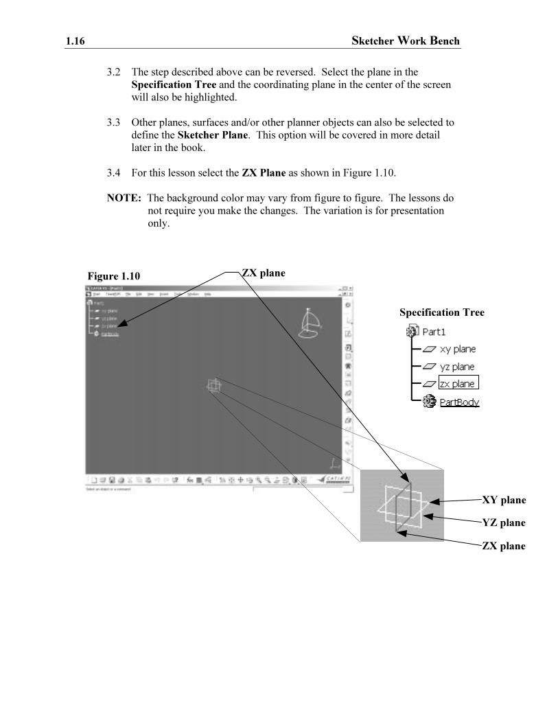
3.1 Select (highlight) the desired plane from the graphical representation in
the center of the screen as shown in Figure 1.10. Notice, as a particular
plane is selected, the equivalent plane in the Specification Tree is
highlighted. If the Specification Tree isn’t showing the branches with the
plane it will need to be expanded. To do this, select the Plus symbol to
the left of the Specification Tree or double click on the branch you want
expanded.
Welcome To CATIA V5 window
Selecting the current work bench brings
up the Welcome To CATIA V5
window.
Sketcher Work
Bench
1.16 Sketcher Work Bench
XY plane
YZ plane
ZX plane
3.2 The step described above can be reversed. Select the plane in the
Specification Tree and the coordinating plane in the center of the screen
will also be highlighted.
3.3 Other planes, surfaces and/or other planner objects can also be selected to
define the Sketcher Plane. This option will be covered in more detail
later in the book.
3.4 For this lesson select the ZX Plane as shown in Figure 1.10.
NOTE: The background color may vary from figure to figure. The lessons do
not require you make the changes. The variation is for presentation
only.
ZX plane Figure 1.10
Specification Tree
Creating A Simple Part 1.17
4 Entering the Sketcher Work Bench
Once a plane is selected the screen will animate rotating until the selected plane is
parallel to the computer screen (perpendicular to you, true size). The default grid will
also appear. You are now officially in the Sketcher Work Bench, but before you
create the planar profile of the “L Shaped Extrusion” you need to customize the
grid.
5 Customizing The Grid
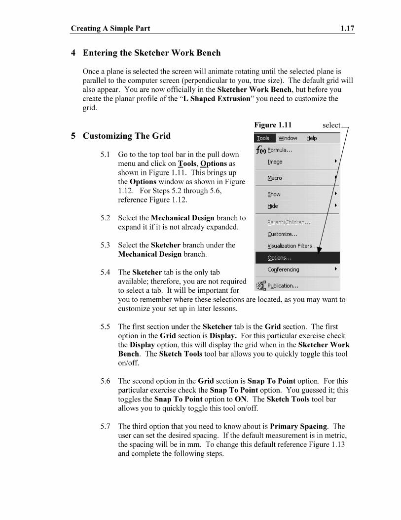
5.1 Go to the top tool bar in the pull down
menu and click on Tools, Options as
shown in Figure 1.11. This brings up
the Options window as shown in Figure
1.12. For Steps 5.2 through 5.6,
reference Figure 1.12.
5.2 Select the Mechanical Design branch to
expand it if it is not already expanded.
5.3 Select the Sketcher branch under the
Mechanical Design branch.
5.4 The Sketcher tab is the only tab
available; therefore, you are not required
to select a tab. It will be important for
you to remember where these selections are located, as you may want to
customize your set up in later lessons.
5.5 The first section under the Sketcher tab is the Grid section. The first
option in the Grid section is Display. For this particular exercise check
the Display option, this will display the grid when in the Sketcher Work
Bench. The Sketch Tools tool bar allows you to quickly toggle this tool
on/off.
5.6 The second option in the Grid section is Snap To Point option. For this
particular exercise check the Snap To Point option. You guessed it; this
toggles the Snap To Point option to ON. The Sketch Tools tool bar
allows you to quickly toggle this tool on/off.
5.7 The third option that you need to know about is Primary Spacing. The
user can set the desired spacing. If the default measurement is in metric,
the spacing will be in mm. To change this default reference Figure 1.13
and complete the following steps.
select Figure 1.11
1.18 Sketcher Work Bench
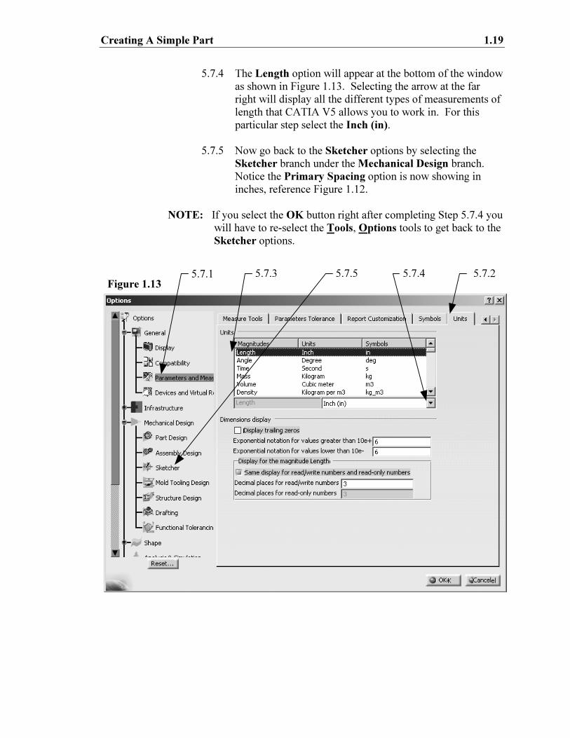
5.7.1 In the Options window and under the General branch
select the Parameters branch. To get the Options
window select the Tools, Options as described in Step 5.1
above.
5.7.2 Select the Units tab. The Options window on the screen
should now look similar to what is shown in Figure 1.13.
5.7.3 The Units box inside the Options window allows you to
select any type of measurement CATIA V5 recognizes.
The scroll bar to the far right of the box allows you to scroll
through the many options. For this particular step select
the Length option.
5.2
5.4 5.5 5.6 5.7 5.8 Figure 1.12
5.3
Creating A Simple Part 1.19
5.7.4 The Length option will appear at the bottom of the window
as shown in Figure 1.13. Selecting the arrow at the far
right will display all the different types of measurements of
length that CATIA V5 allows you to work in. For this
particular step select the Inch (in).
5.7.5 Now go back to the Sketcher options by selecting the
Sketcher branch under the Mechanical Design branch.
Notice the Primary Spacing option is now showing in
inches, reference Figure 1.12.
NOTE: If you select the OK button right after completing Step 5.7.4 you
will have to re-select the Tools, Options tools to get back to the
Sketcher options.
5.7.1 5.7.2 5.7.3 5.7.4 5.7.5 Figure 1.13
1.20 Sketcher Work Bench
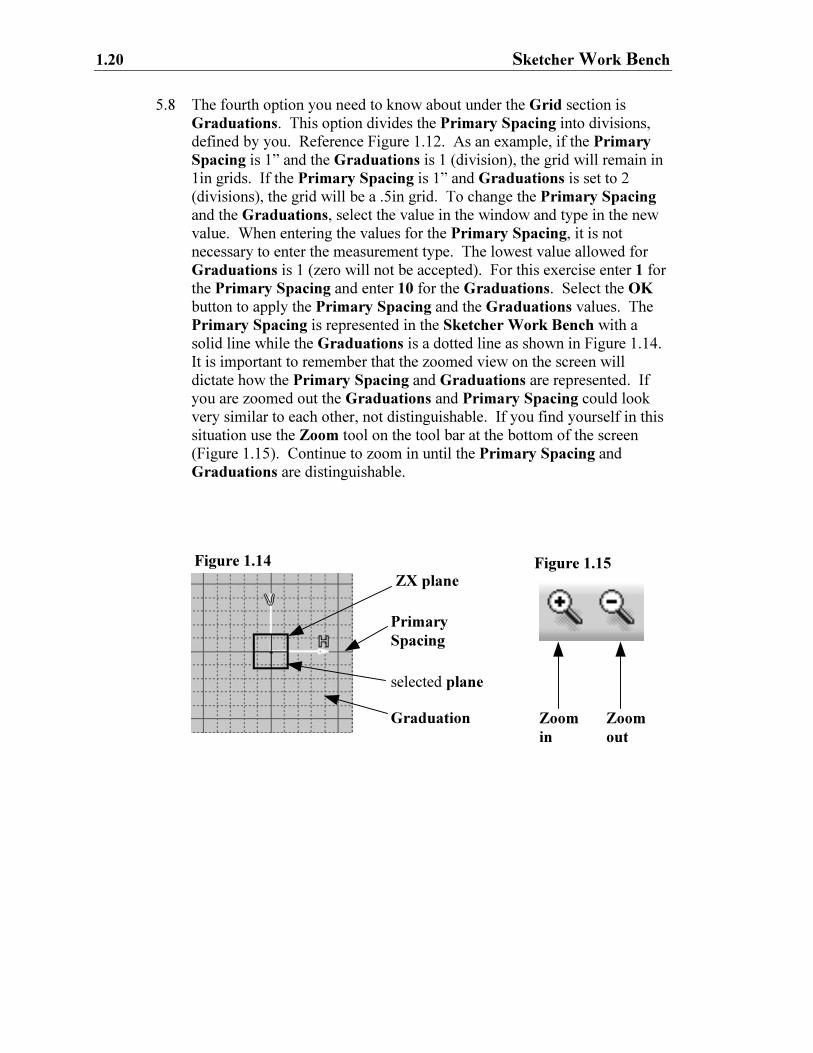
5.8 The fourth option you need to know about under the Grid section is
Graduations. This option divides the Primary Spacing into divisions,
defined by you. Reference Figure 1.12. As an example, if the Primary
Spacing is 1” and the Graduations is 1 (division), the grid will remain in
1in grids. If the Primary Spacing is 1” and Graduations is set to 2
(divisions), the grid will be a .5in grid. To change the Primary Spacing
and the Graduations, select the value in the window and type in the new
value. When entering the values for the Primary Spacing, it is not
necessary to enter the measurement type. The lowest value allowed for
Graduations is 1 (zero will not be accepted). For this exercise enter 1 for
the Primary Spacing and enter 10 for the Graduations. Select the OK
button to apply the Primary Spacing and the Graduations values. The
Primary Spacing is represented in the Sketcher Work Bench with a
solid line while the Graduations is a dotted line as shown in Figure 1.14.
It is important to remember that the zoomed view on the screen will
dictate how the Primary Spacing and Graduations are represented. If
you are zoomed out the Graduations and Primary Spacing could look
very similar to each other, not distinguishable. If you find yourself in this
situation use the Zoom tool on the tool bar at the bottom of the screen
(Figure 1.15). Continue to zoom in until the Primary Spacing and
Graduations are distinguishable.
Primary
Spacing
Graduation
selected plane
Figure 1.14
Zoom
in
Zoom
out
ZX plane Figure 1.15
Creating A Simple Part 1.21
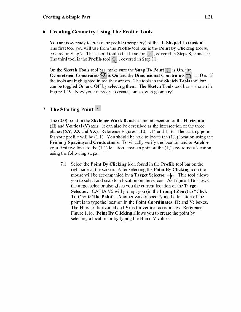
6 Creating Geometry Using The Profile Tools
You are now ready to create the profile (periphery) of the “L Shaped Extrusion”.
The first tool you will use from the Profile tool bar is the Point by Clicking tool ,
covered in Step 7. The second tool is the Line tool , covered in Steps 8, 9 and 10.
The third tool is the Profile tool , covered in Step 11.
On the Sketch Tools tool bar, make sure the Snap To Point is On, the
Geometrical Constraints is On and the Dimensional Constraints is On. If
the tools are highlighted in red they are on. The tools in the Sketch Tools tool bar
can be toggled On and Off by selecting them. The Sketch Tools tool bar is shown in
Figure 1.19. Now you are ready to create some sketch geometry!
7 The Starting Point
The (0,0) point in the Sketcher Work Bench is the intersection of the Horizontal
(H) and Vertical (V) axis. It can also be described as the intersection of the three
planes (XY, ZX and YZ). Reference Figures 1.10, 1.14 and 1.16. The starting point
for your profile will be (1,1). You should be able to locate the (1,1) location using the
Primary Spacing and Graduations. To visually verify the location and to Anchor
your first two lines to the (1,1) location, create a point at the (1,1) coordinate location,
using the following steps.
7.1 Select the Point By Clicking icon found in the Profile tool bar on the
right side of the screen. After selecting the Point By Clicking icon the
mouse will be accompanied by a Target Selector . This tool allows
you to select and snap to a location on the screen. As Figure 1.16 shows,
the target selector also gives you the current location of the Target
Selector. CATIA V5 will prompt you (in the Prompt Zone) to “Click
To Create The Point”. Another way of specifying the location of the
point is to type the location in the Point Coordinates: H: and V: boxes.
The H: is for horizontal and V: is for vertical coordinates. Reference
Figure 1.16. Point By Clicking allows you to create the point by
selecting a location or by typing the H and V values.
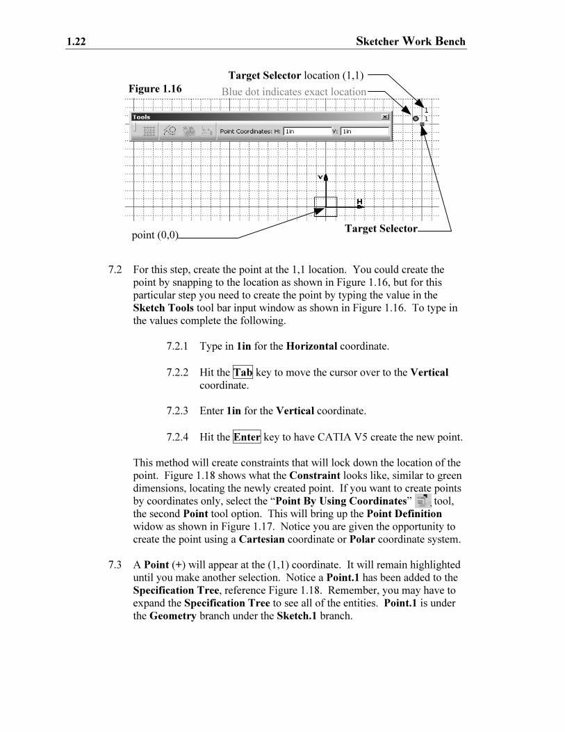
1.22 Sketcher Work Bench
point (0,0)
Target Selector location (1,1)
Blue dot indicates exact location
7.2 For this step, create the point at the 1,1 location. You could create the
point by snapping to the location as shown in Figure 1.16, but for this
particular step you need to create the point by typing the value in the
Sketch Tools tool bar input window as shown in Figure 1.16. To type in
the values complete the following.
7.2.1 Type in 1in for the Horizontal coordinate.
7.2.2 Hit the Tab key to move the cursor over to the Vertical
coordinate.
7.2.3 Enter 1in for the Vertical coordinate.
7.2.4 Hit the Enter key to have CATIA V5 create the new point.
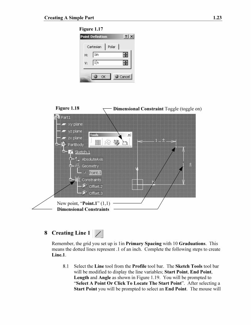
This method will create constraints that will lock down the location of the
point. Figure 1.18 shows what the Constraint looks like, similar to green
dimensions, locating the newly created point. If you want to create points
by coordinates only, select the “Point By Using Coordinates” tool,
the second Point tool option. This will bring up the Point Definition
widow as shown in Figure 1.17. Notice you are given the opportunity to
create the point using a Cartesian coordinate or Polar coordinate system.
7.3 A Point (+) will appear at the (1,1) coordinate. It will remain highlighted
until you make another selection. Notice a Point.1 has been added to the
Specification Tree, reference Figure 1.18. Remember, you may have to
expand the Specification Tree to see all of the entities. Point.1 is under
the Geometry branch under the Sketch.1 branch.
Figure 1.16
Target Selector
Creating A Simple Part 1.23
New point, “Point.1” (1,1)
Figure 1.18
Figure 1.17
Dimensional Constraints
Dimensional Constraint Toggle (toggle on)
8 Creating Line 1
Remember, the grid you set up is 1in Primary Spacing with 10 Graduations. This
means the dotted lines represent .1 of an inch. Complete the following steps to create
Line.1.
8.1 Select the Line tool from the Profile tool bar. The Sketch Tools tool bar
will be modified to display the line variables; Start Point, End Point,
Length and Angle as shown in Figure 1.19. You will be prompted to
“Select A Point Or Click To Locate The Start Point”. After selecting a
Start Point you will be prompted to select an End Point. The mouse will
1.24 Sketcher Work Bench
Figure 1.20
be accompanied by a Target Selector and the current location, same as
when you created the point. Notice that the Line tool bar is similar to the
Point tool bar.
8.2 The starting point for Line.1 will be Point.1 that was created in Step 7.
Using your mouse, select Point.1. You will now be prompted to “Select
A Point Or Click To Locate The End Point”. The Sketch Tools tool
bar window will also update to prompt for the End Point.
8.3 The end point for Line.1 is (1,2). If you can use the grid to locate the
correct location, do so. Move your Target Selector up one full grid line,
but don’t move it to the right or left (0 in the horizontal direction). Click
on the grid line intersection (1,2). If you have any doubt where (1,2) is,
type in the values using the Sketch Tools tool bar. Type in 1 for the H:
box and 2 for the V: box.
8.4 The first line is now created. Line.1 should look similar to the one shown
in Figure 1.21.
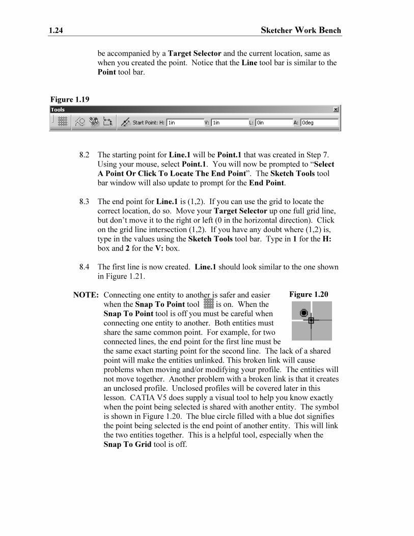
NOTE: Connecting one entity to another is safer and easier
when the Snap To Point tool is on. When the
Snap To Point tool is off you must be careful when
connecting one entity to another. Both entities must
share the same common point. For example, for two
connected lines, the end point for the first line must be
the same exact starting point for the second line. The lack of a shared
point will make the entities unlinked. This broken link will cause
problems when moving and/or modifying your profile. The entities will
not move together. Another problem with a broken link is that it creates
an unclosed profile. Unclosed profiles will be covered later in this
lesson. CATIA V5 does supply a visual tool to help you know exactly
when the point being selected is shared with another entity. The symbol
is shown in Figure 1.20. The blue circle filled with a blue dot signifies
the point being selected is the end point of another entity. This will link
the two entities together. This is a helpful tool, especially when the
Snap To Grid tool is off.
Figure 1.19
Creating A Simple Part 1.25
Figure 1.21
(1,2)
NOTE: The Sketch Tools tool bar gives you more options than the ones covered
in Steps 8.1 thru 8.3. If you are typing in the information to create a
line, you have the option of giving Polar Coordinate information,
reference Figure 1.19. You enter a Start Point, L: (length of line) and
A: (for angle). Though this lesson does not require you to use this
option, it could be helpful in the future.
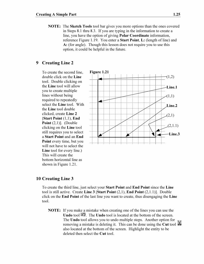
9 Creating Line 2
To create the second line,
double click on the Line
tool. Double clicking on
the Line tool will allow
you to create multiple
lines without being
required to repeatedly
select the Line tool. With
the Line tool double
clicked, create Line 2
[Start Point (1,1), End
Point (2,1)]. (Double
clicking on the Line tool
still requires you to select
a Start Point and an End
Point every time, but you
will not have to select the
Line tool for every line.)
This will create the
bottom horizontal line as
shown in Figure 1.21.
10 Creating Line 3
To create the third line, just select your Start Point and End Point since the Line
tool is still active. Create Line 3 [Start Point (2,1), End Point (2,1.1)]. Double
click on the End Point of the last line you want to create, thus disengaging the Line
tool.
NOTE: If you make a mistake when creating one of the lines you can use the
Undo tool . The Undo tool is located at the bottom of the screen.
The Undo tool allows you to undo multiple steps. Another option for
removing a mistake is deleting it. This can be done using the Cut tool
also located at the bottom of the screen. Highlight the entity to be
deleted then select the Cut tool.
Line.2
Line.3
(1,1)
Line.1
(2,1.1)
(2,1)
1.26 Sketcher Work Bench
Figure 1.22
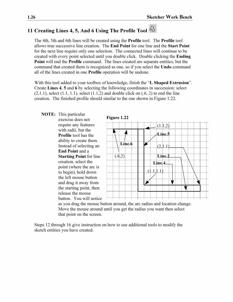
11 Creating Lines 4, 5, And 6 Using The Profile Tool
The 4th, 5th and 6th lines will be created using the Profile tool. The Profile tool
allows true successive line creation. The End Point for one line and the Start Point
for the next line require only one selection. The connected lines will continue to be
created with every point selected until you double click. Double clicking the Ending
Point will end the Profile command. The lines created are separate entities, but the
command that created them is recognized as one, so if you select the Undo command
all of the lines created in one Profile operation will be undone.
With this tool added to your toolbox of knowledge, finish the “L Shaped Extrusion”.
Create Lines 4, 5 and 6 by selecting the following coordinates in succession: select
(2,1.1), select (1.1, 1.1), select (1.1,2) and double click on (.6, 2) to end the line
creation. The finished profile should similar to the one shown in Figure 1.22.
NOTE: This particular
exercise does not
require any features
with radii, but the
Profile tool has the
ability to create them.
Instead of selecting an
End Point and a
Starting Point for line
creation, select the
point (where the arc is
to begin), hold down
the left mouse button
and drag it away from
the starting point, then
release the mouse
button. You will notice
as you drag the mouse button around, the arc radius and location change.
Move the mouse around until you get the radius you want then select
that point on the screen.
Steps 12 through 16 give instruction on how to use additional tools to modify the
sketch entities you have created.
(1.1,2)
Line.5
(1.1,1.1)
Line.4
(2,1.1)
Line.2
Line.6
(.6,2)
Creating A Simple Part 1.27
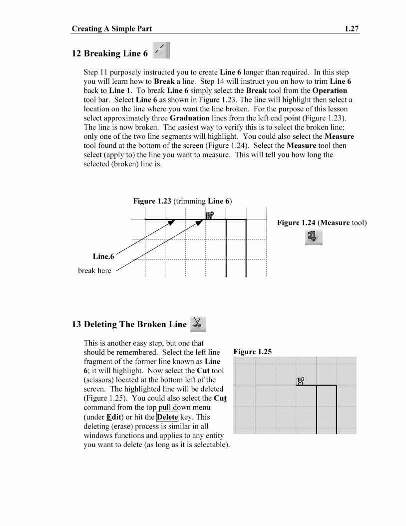
12 Breaking Line 6
Step 11 purposely instructed you to create Line 6 longer than required. In this step
you will learn how to Break a line. Step 14 will instruct you on how to trim Line 6
back to Line 1. To break Line 6 simply select the Break tool from the Operation
tool bar. Select Line 6 as shown in Figure 1.23. The line will highlight then select a
location on the line where you want the line broken. For the purpose of this lesson
select approximately three Graduation lines from the left end point (Figure 1.23).
The line is now broken. The easiest way to verify this is to select the broken line;
only one of the two line segments will highlight. You could also select the Measure
tool found at the bottom of the screen (Figure 1.24). Select the Measure tool then
select (apply to) the line you want to measure. This will tell you how long the
selected (broken) line is.
13 Deleting The Broken Line
This is another easy step, but one that
should be remembered. Select the left line
fragment of the former line known as Line
6; it will highlight. Now select the Cut tool
(scissors) located at the bottom left of the
screen. The highlighted line will be deleted
(Figure 1.25). You could also select the Cut
command from the top pull down menu
(under Edit) or hit the Delete key. This
deleting (erase) process is similar in all
windows functions and applies to any entity
you want to delete (as long as it is selectable).
Line.6
break here
Figure 1.23 (trimming Line 6)
Figure 1.25
Figure 1.24 (Measure tool)
1.28 Sketcher Work Bench
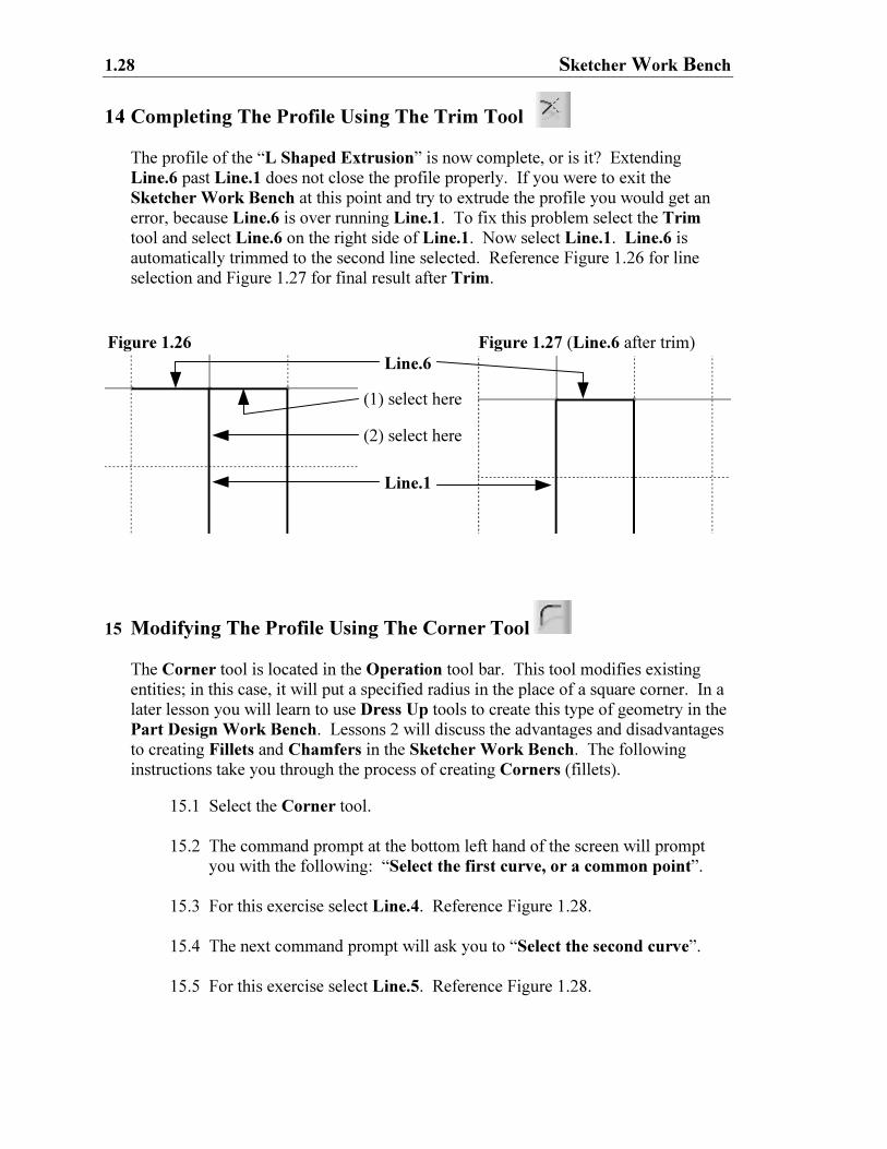
14 Completing The Profile Using The Trim Tool
The profile of the “L Shaped Extrusion” is now complete, or is it? Extending
Line.6 past Line.1 does not close the profile properly. If you were to exit the
Sketcher Work Bench at this point and try to extrude the profile you would get an
error, because Line.6 is over running Line.1. To fix this problem select the Trim
tool and select Line.6 on the right side of Line.1. Now select Line.1. Line.6 is
automatically trimmed to the second line selected. Reference Figure 1.26 for line
selection and Figure 1.27 for final result after Trim.
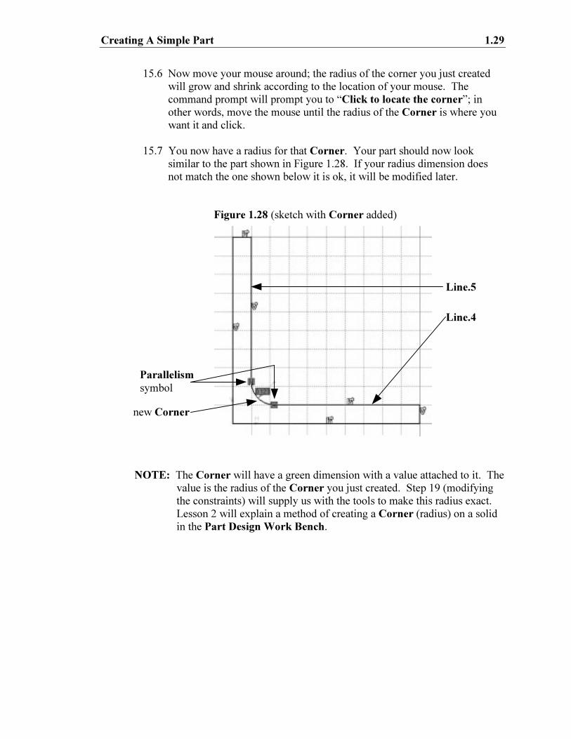
15 Modifying The Profile Using The Corner Tool
The Corner tool is located in the Operation tool bar. This tool modifies existing
entities; in this case, it will put a specified radius in the place of a square corner. In a
later lesson you will learn to use Dress Up tools to create this type of geometry in the
Part Design Work Bench. Lessons 2 will discuss the advantages and disadvantages
to creating Fillets and Chamfers in the Sketcher Work Bench. The following
instructions take you through the process of creating Corners (fillets).
15.1 Select the Corner tool.
15.2 The command prompt at the bottom left hand of the screen will prompt
you with the following: “Select the first curve, or a common point”.
15.3 For this exercise select Line.4. Reference Figure 1.28.
15.4 The next command prompt will ask you to “Select the second curve”.
15.5 For this exercise select Line.5. Reference Figure 1.28.
Figure 1.26 Figure 1.27 (Line.6 after trim)
(1) select here
(2) select here
Line.1
Line.6
Creating A Simple Part 1.29
15.6 Now move your mouse around; the radius of the corner you just created
will grow and shrink according to the location of your mouse. The
command prompt will prompt you to “Click to locate the corner”; in
other words, move the mouse until the radius of the Corner is where you
want it and click.
15.7 You now have a radius for that Corner. Your part should now look
similar to the part shown in Figure 1.28. If your radius dimension does
not match the one shown below it is ok, it will be modified later.
NOTE: The Corner will have a green dimension with a value attached to it. The
value is the radius of the Corner you just created. Step 19 (modifying
the constraints) will supply us with the tools to make this radius exact.
Lesson 2 will explain a method of creating a Corner (radius) on a solid
in the Part Design Work Bench.
Figure 1.28 (sketch with Corner added)
new Corner
Parallelism
symbol
Line.4
Line.5
1.30 Sketcher Work Bench
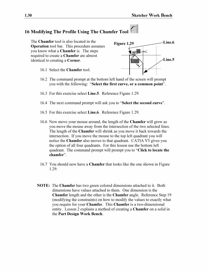
16 Modifying The Profile Using The Chamfer Tool
The Chamfer tool is also located in the
Operation tool bar. This procedure assumes
you know what a Chamfer is. The steps
required to create a Chamfer are almost
identical to creating a Corner.
16.1 Select the Chamfer tool.
16.2 The command prompt at the bottom left hand of the screen will prompt
you with the following: “Select the first curve, or a common point”.
16.3 For this exercise select Line.5. Reference Figure 1.29.
16.4 The next command prompt will ask you to “Select the second curve”.
16.5 For this exercise select Line.6. Reference Figure 1.29.
16.6 Now move your mouse around, the length of the Chamfer will grow as
you move the mouse away from the intersection of the two selected lines.
The length of the Chamfer will shrink as you move it back towards the
intersection. If you move the mouse to the top left quadrant you will
notice the Chamfer also moves to that quadrant. CATIA V5 gives you
the option of all four quadrants. For this lesson use the bottom left
quadrant. The command prompt will prompt you to “Click to locate the
chamfer”.
16.7 You should now have a Chamfer that looks like the one shown in Figure
1.29.
NOTE: The Chamfer has two green colored dimensions attached to it. Both
dimensions have values attached to them. One dimension is the
Chamfer length and the other is the Chamfer angle. Reference Step 19
(modifying the constraints) on how to modify the values to exactly what
you require for your Chamfer. This Chamfer is a two-dimensional
entity. Lesson 2 explains a method of creating a Chamfer on a solid in
the Part Design Work Bench.
Figure 1.29
Line.5
Line.6
Creating A Simple Part 1.31
Figure 1.30
17 Anchoring The Profile Using The Anchor Tool
Select Line.6. As you select the line hold the mouse button down. Now drag the
mouse up. Notice that the entire profile expands and contracts as you drag the mouse
button around. Lines 1 and 2 can be modified in length, but the location can’t
change. All of the other lines can be modified in position, length and angle. You
cannot modify the location of Lines 1 and 2 because they are linked to Point.1 and
Point.1 is constrained to the location (1,1). The green dimension lines that were
created with Point.1 are constraints. It is the constraint values that tie Point.1, Line.1
and Line.2 to their current positions. To move the point and/or either line you have
to modify the constraint. This will be covered in Step 19.
If there is a particular entity you don’t want to move in relationship to another entity,
you can constrain it. Constraints are restrictions on one entity to another entity. The
Anchor tool restricts the entities movement in relationship to the coordinate location
only. Lines 1 and 2 are not truly anchored because the constraint has tied their
relationship to Point.1. The effect is the same; Lines 1 and 2 cannot be moved. If
you want to constrain the location of an entity without constraining any other entity,
the Anchor tool is a good option. For example, you may want to modify the “L
Shaped Extrusion”, but you know you don’t want Line.6 to move at all. You can
restrict Line.6 by Anchoring it. Elements can be Anchored by completing the
following steps.
17.1 Select the entity that you want to Anchor. For this lesson select Line 6.
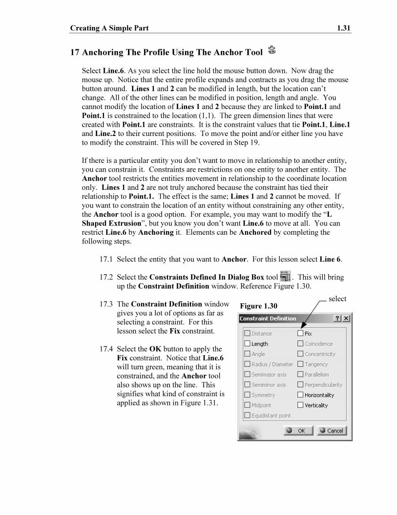
17.2 Select the Constraints Defined In Dialog Box tool . This will bring
up the Constraint Definition window. Reference Figure 1.30.
17.3 The Constraint Definition window
gives you a lot of options as far as
selecting a constraint. For this
lesson select the Fix constraint.
17.4 Select the OK button to apply the
Fix constraint. Notice that Line.6
will turn green, meaning that it is
constrained, and the Anchor tool
also shows up on the line. This
signifies what kind of constraint is
applied as shown in Figure 1.31.
select
1.32 Sketcher Work Bench
Figure 1.31
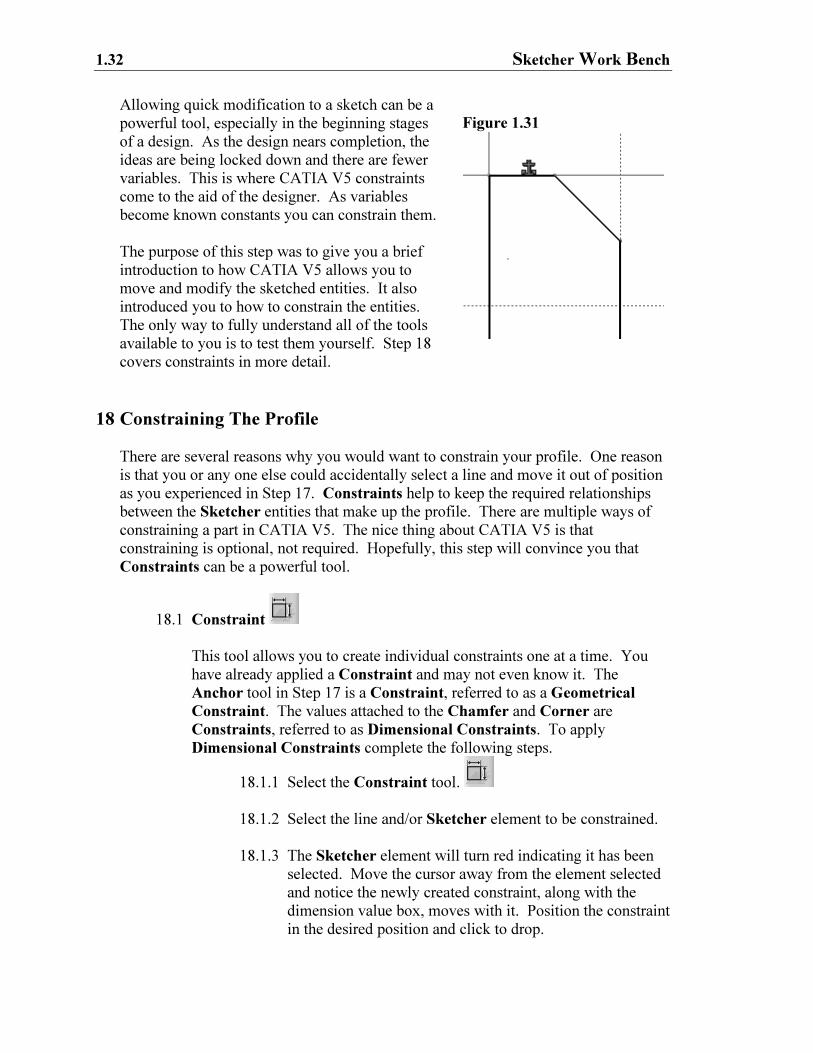
Allowing quick modification to a sketch can be a
powerful tool, especially in the beginning stages
of a design. As the design nears completion, the
ideas are being locked down and there are fewer
variables. This is where CATIA V5 constraints
come to the aid of the designer. As variables
become known constants you can constrain them.
The purpose of this step was to give you a brief
introduction to how CATIA V5 allows you to
move and modify the sketched entities. It also
introduced you to how to constrain the entities.
The only way to fully understand all of the tools
available to you is to test them yourself. Step 18
covers constraints in more detail.
18 Constraining The Profile
There are several reasons why you would want to constrain your profile. One reason
is that you or any one else could accidentally select a line and move it out of position
as you experienced in Step 17. Constraints help to keep the required relationships
between the Sketcher entities that make up the profile. There are multiple ways of
constraining a part in CATIA V5. The nice thing about CATIA V5 is that
constraining is optional, not required. Hopefully, this step will convince you that
Constraints can be a powerful tool.
18.1 Constraint
This tool allows you to create individual constraints one at a time. You
have already applied a Constraint and may not even know it. The
Anchor tool in Step 17 is a Constraint, referred to as a Geometrical
Constraint. The values attached to the Chamfer and Corner are
Constraints, referred to as Dimensional Constraints. To apply
Dimensional Constraints complete the following steps.
18.1.1 Select the Constraint tool.
18.1.2 Select the line and/or Sketcher element to be constrained.
18.1.3 The Sketcher element will turn red indicating it has been
selected. Move the cursor away from the element selected
and notice the newly created constraint, along with the
dimension value box, moves with it. Position the constraint
in the desired position and click to drop.
Creating A Simple Part 1.33
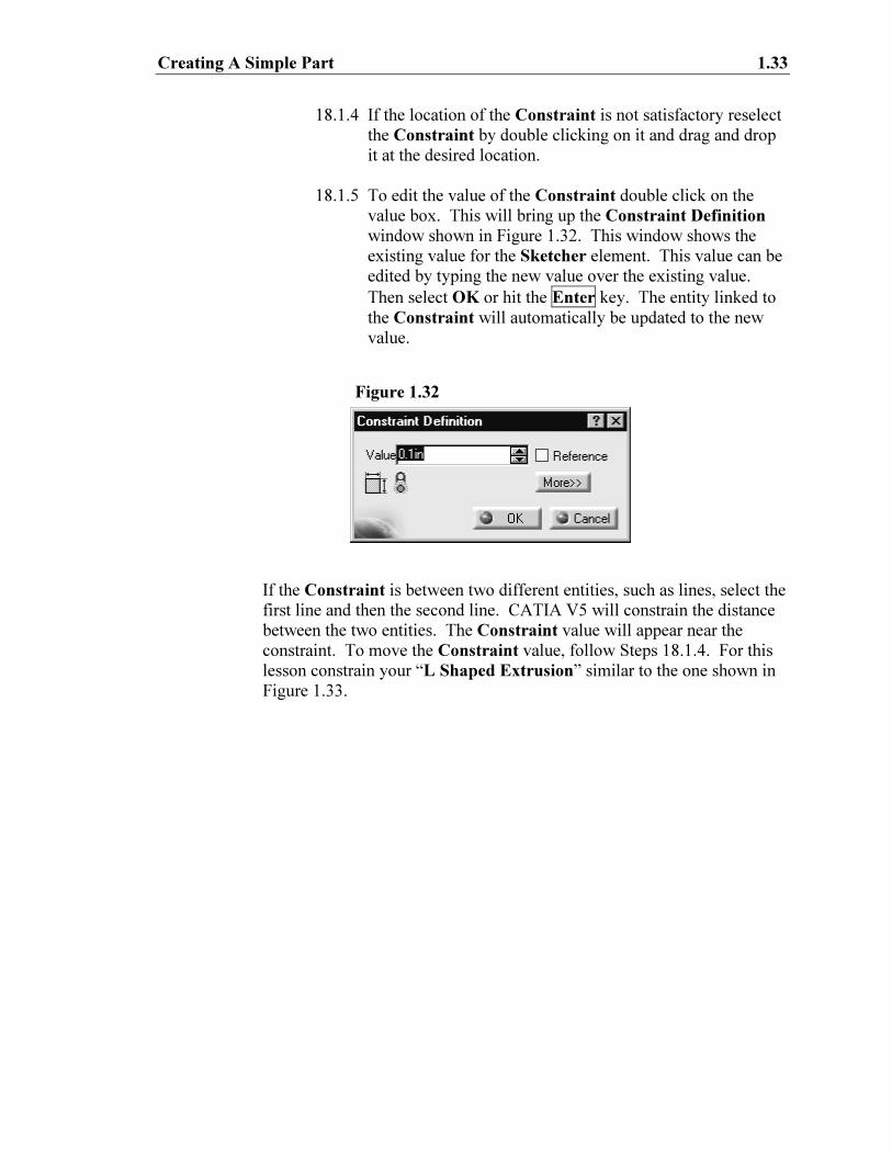
Figure 1.32
18.1.4 If the location of the Constraint is not satisfactory reselect
the Constraint by double clicking on it and drag and drop
it at the desired location.
18.1.5 To edit the value of the Constraint double click on the
value box. This will bring up the Constraint Definition
window shown in Figure 1.32. This window shows the
existing value for the Sketcher element. This value can be
edited by typing the new value over the existing value.
Then select OK or hit the Enter key. The entity linked to
the Constraint will automatically be updated to the new
value.
If the Constraint is between two different entities, such as lines, select the
first line and then the second line. CATIA V5 will constrain the distance
between the two entities. The Constraint value will appear near the
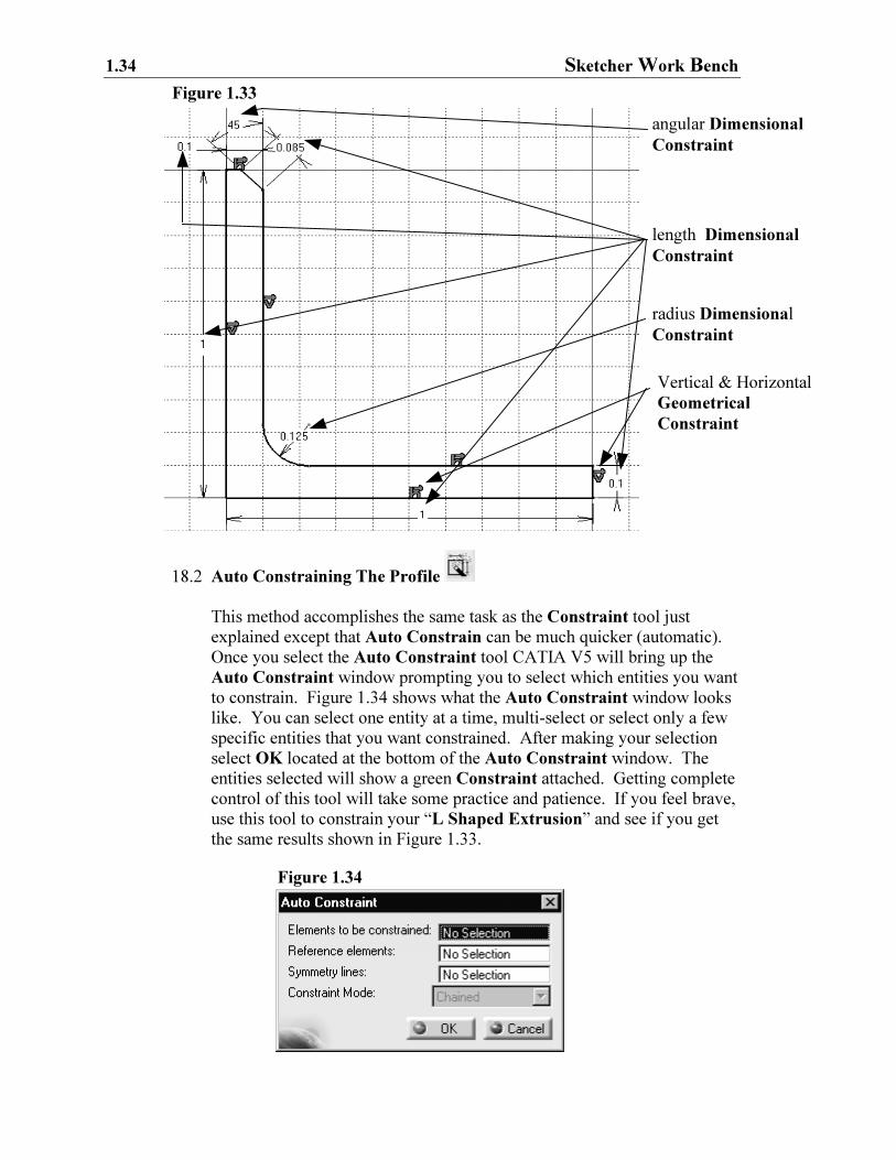
constraint. To move the Constraint value, follow Steps 18.1.4. For this
lesson constrain your “L Shaped Extrusion” similar to the one shown in
Figure 1.33.
1.34 Sketcher Work Bench
18.2 Auto Constraining The Profile
This method accomplishes the same task as the Constraint tool just
explained except that Auto Constrain can be much quicker (automatic).
Once you select the Auto Constraint tool CATIA V5 will bring up the
Auto Constraint window prompting you to select which entities you want
to constrain. Figure 1.34 shows what the Auto Constraint window looks
like. You can select one entity at a time, multi-select or select only a few
specific entities that you want constrained. After making your selection
select OK located at the bottom of the Auto Constraint window. The
entities selected will show a green Constraint attached. Getting complete
control of this tool will take some practice and patience. If you feel brave,
use this tool to constrain your “L Shaped Extrusion” and see if you get
the same results shown in Figure 1.33.
length Dimensional
Constraint
radius Dimensional
Constraint
angular Dimensional
Constraint
Vertical & Horizontal
Geometrical
Constraint
Figure 1.33
Figure 1.34
Creating A Simple Part 1.35
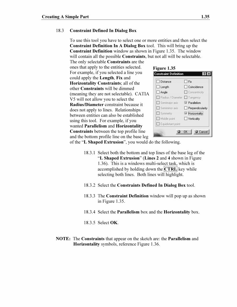
18.3 Constraint Defined In Dialog Box
To use this tool you have to select one or more entities and then select the
Constraint Definition In A Dialog Box tool. This will bring up the
Constraint Definition window as shown in Figure 1.35. The window
will contain all the possible Constraints, but not all will be selectable.
The only selectable Constraints are the
ones that apply to the entities selected.
For example, if you selected a line you
could apply the Length, Fix and
Horizontality Constraints; all of the
other Constraints will be dimmed
(meaning they are not selectable). CATIA
V5 will not allow you to select the
Radius/Diameter constraint because it
does not apply to lines. Relationships
between entities can also be established
using this tool. For example, if you
wanted Parallelism and Horizontality
Constraints between the top profile line
and the bottom profile line on the base leg
of the “L Shaped Extrusion”, you would do the following.
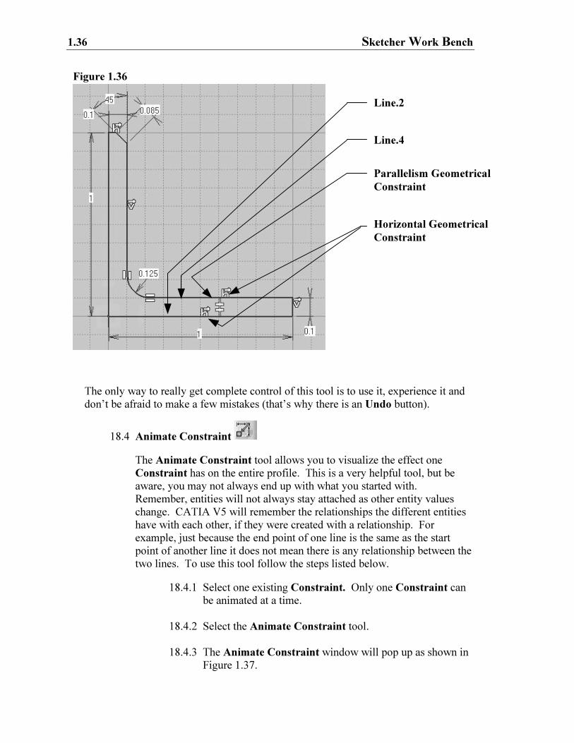
18.3.1 Select both the bottom and top lines of the base leg of the
“L Shaped Extrusion” (Lines 2 and 4 shown in Figure
1.36). This is a windows multi-select task, which is
accomplished by holding down the CTRL key while
selecting both lines. Both lines will highlight.
18.3.2 Select the Constraints Defined In Dialog Box tool.
18.3.3 The Constraint Definition window will pop up as shown
in Figure 1.35.
18.3.4 Select the Parallelism box and the Horizontality box.
18.3.5 Select OK.
NOTE: The Constraints that appear on the sketch are: the Parallelism and
Horizontality symbols, reference Figure 1.36.
Figure 1.35
1.36 Sketcher Work Bench
The only way to really get complete control of this tool is to use it, experience it and
don’t be afraid to make a few mistakes (that’s why there is an Undo button).
18.4 Animate Constraint
The Animate Constraint tool allows you to visualize the effect one
Constraint has on the entire profile. This is a very helpful tool, but be
aware, you may not always end up with what you started with.
Remember, entities will not always stay attached as other entity values
change. CATIA V5 will remember the relationships the different entities
have with each other, if they were created with a relationship. For
example, just because the end point of one line is the same as the start
point of another line it does not mean there is any relationship between the
two lines. To use this tool follow the steps listed below.
18.4.1 Select one existing Constraint. Only one Constraint can
be animated at a time.
18.4.2 Select the Animate Constraint tool.
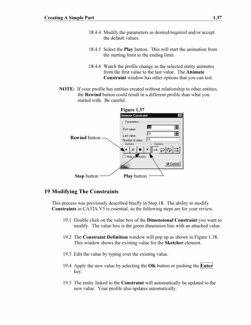
18.4.3 The Animate Constraint window will pop up as shown in
Figure 1.37.
Figure 1.36
Horizontal Geometrical
Constraint
Parallelism Geometrical
Constraint
Line.2
Line.4
Creating A Simple Part 1.37
18.4.4 Modify the parameters as desired/required and/or accept
the default values.
18.4.5 Select the Play button. This will start the animation from
the starting limit to the ending limit.
18.4.6 Watch the profile change as the selected entity animates
from the first value to the last value. The Animate
Constraint window has other options that you can test.
NOTE: If your profile has entities created without relationship to other entities,
the Rewind button could result in a different profile than what you
started with. Be careful.
19 Modifying The Constraints
This process was previously described briefly in Step 18. The ability to modify
Constraints in CATIA V5 is essential, so the following steps are for your review.
19.1 Double click on the value box of the Dimensional Constraint you want to
modify. The value box is the green dimension line with an attached value.
19.2 The Constraint Definition window will pop up as shown in Figure 1.38.
This window shows the existing value for the Sketcher element.
19.3 Edit the value by typing over the existing value.
19.4 Apply the new value by selecting the OK button or pushing the Enter
key.
19.5 The entity linked to the Constraint will automatically be updated to the
new value. Your profile also updates automatically.
Play button
Rewind button
Stop button
Figure 1.37
1.38 Sketcher Work Bench
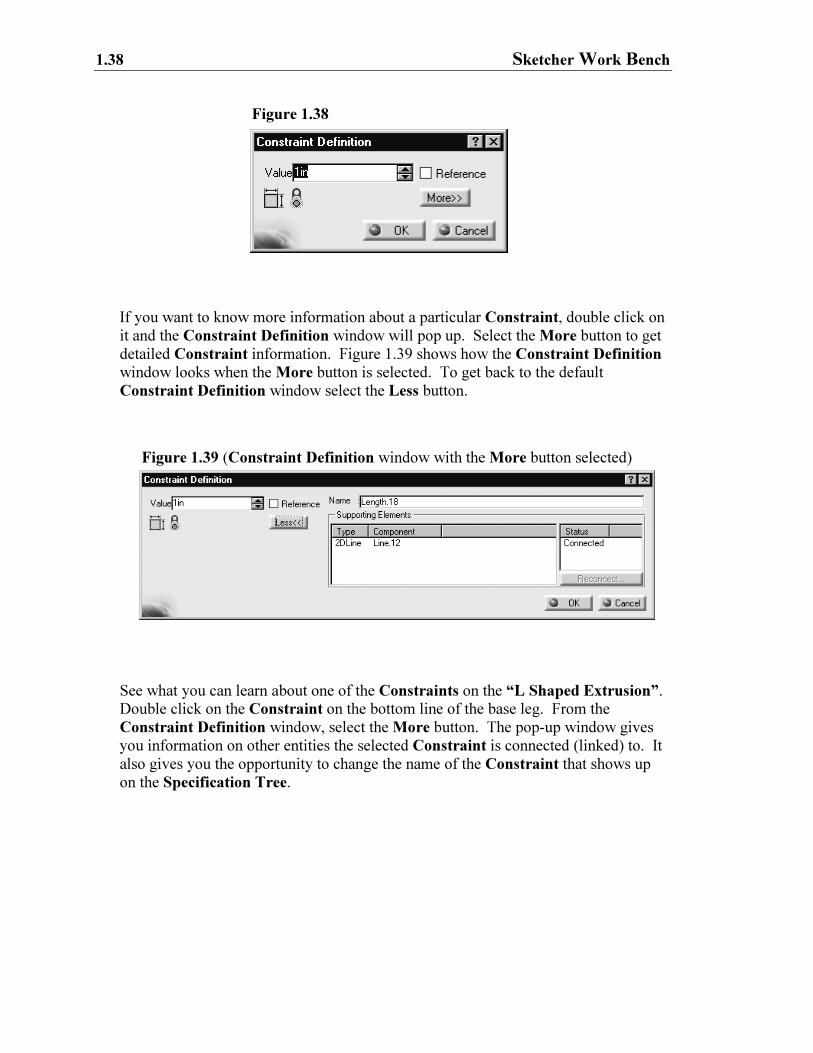
If you want to know more information about a particular Constraint, double click on
it and the Constraint Definition window will pop up. Select the More button to get
detailed Constraint information. Figure 1.39 shows how the Constraint Definition
window looks when the More button is selected. To get back to the default
Constraint Definition window select the Less button.
See what you can learn about one of the Constraints on the “L Shaped Extrusion”.
Double click on the Constraint on the bottom line of the base leg. From the
Constraint Definition window, select the More button. The pop-up window gives
you information on other entities the selected Constraint is connected (linked) to. It
also gives you the opportunity to change the name of the Constraint that shows up
on the Specification Tree.
Figure 1.39 (Constraint Definition window with the More button selected)
Figure 1.38
Creating A Simple Part 1.39
20 Over Constraining The Profile… Not A Good Thing!
It is possible to over constrain a profile in the Sketcher Work Bench. When you
over constrain the profile CATIA V5 will inform you that you have a problem. The
CATIA V5 definition of over constraining is putting two different Constraints on
one or more entities. The two Constraints can be correct individually, but
collectively have conflicting values. When an over constrained condition exists
CATIA V5 will turn all of the affected constraining values purple. Purple is the
default color for over constrained sketches! Remember, an Over Constraint
condition is not a good thing. CATIA V5 will not allow you to extrude an over
constrained profile. The easiest way to get out of the over constrained condition is to
Undo or Cut the last Constraint created, the Constraint that caused the over
constrained condition. You must reconsider which Constraints are necessary to
accomplish what you want. In the case of the “L Shaped Extrusion”, you are
creating the Constraints that are used to maintain the specified dimensions. If your
profile is not over constrained, you are ready to move on to the next step. If the
instructions were followed an over constrained condition should not exist.
21 Exiting The Sketcher Work Bench
If your “L Shaped Extrusion” is similar to the one shown in Figure 1.33, you are
ready to move the profile into the 3D world, the Part Design Work Bench. As a
reminder, the following conditions will not allow you to successfully extrude your
profile once out of the Sketcher Work Bench.
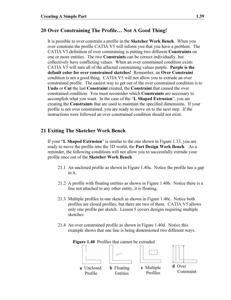
21.1 An unclosed profile as shown in Figure 1.40a. Notice the profile has a gap
in it.
21.2 A profile with floating entities as shown in Figure 1.40b. Notice there is a
line not attached to any other entity, it is floating.
21.3 Multiple profiles in one sketch as shown in Figure 1.40c. Notice both
profiles are closed profiles, but there are two of them. CATIA V5 allows
only one profile per sketch. Lesson 5 covers designs requiring multiple
sketches.
21.4 An over constrained profile as shown in Figure 1.40d. Notice this
example shows that one line is being dimensioned two different ways.
a Unclosed
Profile
b Floating
Entities
c Multiple
Profiles
Figure 1.40 Profiles that cannot be extruded
d Over
Constraint
1.40 Sketcher Work Bench
You can exit the Sketcher Work Bench with your profile in any of the above
conditions, but CATIA V5 will not extrude the profile into a three-dimensional
(solid) part.
If you are ready to exit the Sketcher Work Bench, select the Exit tool . The
Exit tool is located at the top right of the Sketcher Work Bench.
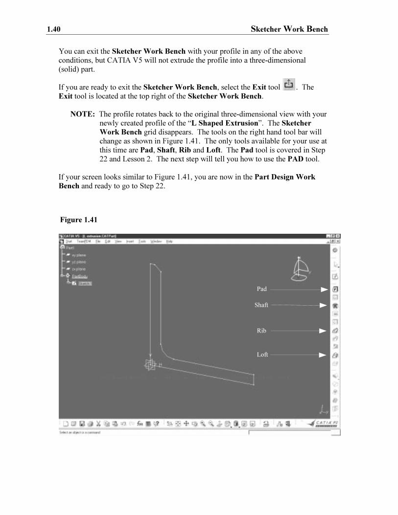
NOTE: The profile rotates back to the original three-dimensional view with your
newly created profile of the “L Shaped Extrusion”. The Sketcher
Work Bench grid disappears. The tools on the right hand tool bar will
change as shown in Figure 1.41. The only tools available for your use at
this time are Pad, Shaft, Rib and Loft. The Pad tool is covered in Step
22 and Lesson 2. The next step will tell you how to use the PAD tool.
If your screen looks similar to Figure 1.41, you are now in the Part Design Work
Bench and ready to go to Step 22.
Pad
Shaft
Loft
Rib
Figure 1.41
Creating A Simple Part 1.41
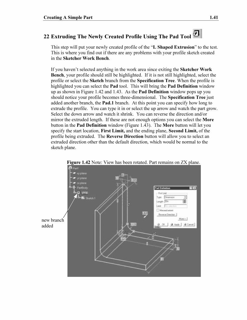
22 Extruding The Newly Created Profile Using The Pad Tool
This step will put your newly created profile of the “L Shaped Extrusion” to the test.
This is where you find out if there are any problems with your profile sketch created
in the Sketcher Work Bench.
If you haven’t selected anything in the work area since exiting the Sketcher Work
Bench, your profile should still be highlighted. If it is not still highlighted, select the
profile or select the Sketch branch from the Specification Tree. When the profile is
highlighted you can select the Pad tool. This will bring the Pad Definition window
up as shown in Figure 1.42 and 1.43. As the Pad Definition window pops up you
should notice your profile becomes three-dimensional. The Specification Tree just
added another branch, the Pad.1 branch. At this point you can specify how long to
extrude the profile. You can type it in or select the up arrow and watch the part grow.
Select the down arrow and watch it shrink. You can reverse the direction and/or
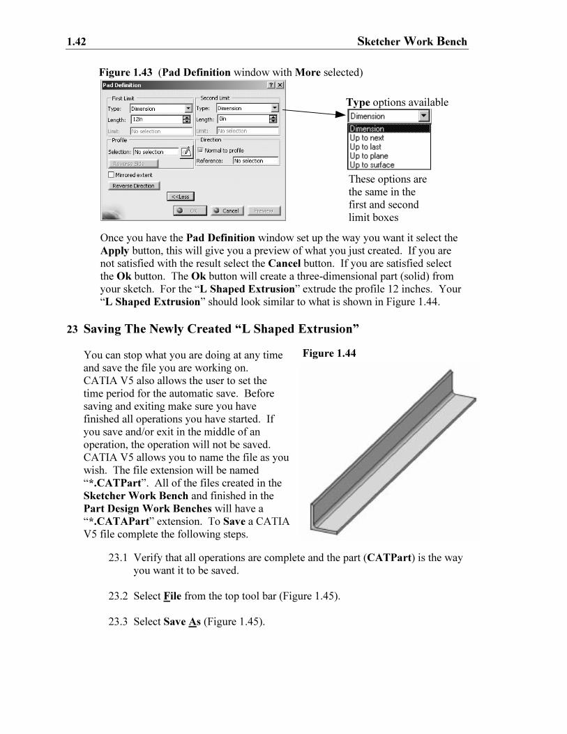
mirror the extruded length. If these are not enough options you can select the More
button in the Pad Definition window (Figure 1.43). The More button will let you
specify the start location, First Limit, and the ending plane, Second Limit, of the
profile being extruded. The Reverse Direction button will allow you to select an
extruded direction other than the default direction, which would be normal to the
sketch plane.
Figure 1.42 Note: View has been rotated. Part remains on ZX plane.
new branch
added
1.42 Sketcher Work Bench
Figure 1.44
Once you have the Pad Definition window set up the way you want it select the
Apply button, this will give you a preview of what you just created. If you are
not satisfied with the result select the Cancel button. If you are satisfied select
the Ok button. The Ok button will create a three-dimensional part (solid) from
your sketch. For the “L Shaped Extrusion” extrude the profile 12 inches. Your
“L Shaped Extrusion” should look similar to what is shown in Figure 1.44.
23 Saving The Newly Created “L Shaped Extrusion”
You can stop what you are doing at any time
and save the file you are working on.
CATIA V5 also allows the user to set the
time period for the automatic save. Before
saving and exiting make sure you have
finished all operations you have started. If
you save and/or exit in the middle of an
operation, the operation will not be saved.
CATIA V5 allows you to name the file as you
wish. The file extension will be named
“*.CATPart”. All of the files created in the
Sketcher Work Bench and finished in the
Part Design Work Benches will have a
“*.CATAPart” extension. To Save a CATIA
V5 file complete the following steps.
23.1 Verify that all operations are complete and the part (CATPart) is the way
you want it to be saved.
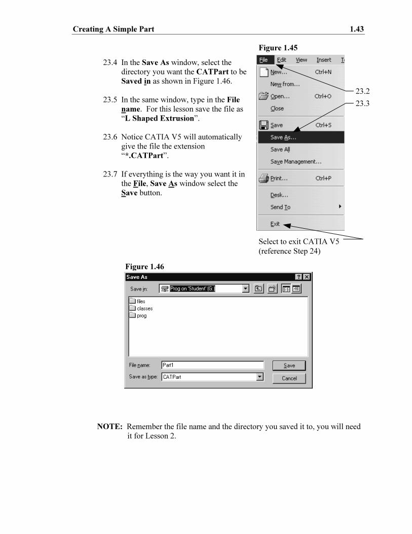
23.2 Select File from the top tool bar (Figure 1.45).
23.3 Select Save As (Figure 1.45).
These options are
the same in the
first and second
limit boxes
Type options available
Figure 1.43 (Pad Definition window with More selected)
Creating A Simple Part 1.43
23.4 In the Save As window, select the
directory you want the CATPart to be
Saved in as shown in Figure 1.46.
23.5 In the same window, type in the File
name. For this lesson save the file as
“L Shaped Extrusion”.
23.6 Notice CATIA V5 will automatically
give the file the extension
“*.CATPart”.
23.7 If everything is the way you want it in
the File, Save As window select the
Save button.
NOTE: Remember the file name and the directory you saved it to, you will need
it for Lesson 2.
23.2
23.3
Figure 1.46
Figure 1.45
Select to exit CATIA V5
(reference Step 24)
1.44 Sketcher Work Bench
24 Exiting CATIA V5
To exit CATIA V5, complete the following steps.
24.1 Make sure you saved the CATPart (if you wanted it saved). If you have
made any changes to the CATPart and not saved CATIA V5 will prompt
you to save when exiting.
24.2 Select File from the top pull down tool bar as shown in Figure 1.45.
24.3 Select Exit.
24.4 If the CATPart was previously saved CATIA V5 will shut down and your
computer will go back to the NT Desktop. As described above, if some
changes were made to the CATPart without being saved CATIA V5 will
prompt you to “Save” before allowing you to exit to the NT Desktop.
Lesson 1 Summary
If you are not use to the concepts of a sketch tool and parameterized entities this can
be a difficult lesson, a lot of people struggle with it. It is not difficult it is just
different! It is critical that you get comfortable with these two concepts before
moving on to the next lesson. After you spend enough time using this process you
will learn to appreciate the power these concepts possess.
Creating A Simple Part 1.45
Lesson 1 Review
After completing this lesson you should be able to answer the questions and explain the
concepts listed below.
1. What is the definition of a Constraint?
2. Does CATIA V5 require Constraints to create a profile in the Sketcher
Work Bench?
3. What is meant by an unclosed profile?
4. T or F Unclosed profiles can be extruded using the Pad tool.
5. T or F There is more than one way to select the XY plane when defining the
XY plane as a sketch plane.
6. T or F Over Constraining a profile is a good thing!
7. Explain your answer to question 6.
8. What does Anchoring the profile do in the Sketcher Work Bench?
9. Explain how you would change the Sketcher units of measurements from mm
to inches.
10. The Sketcher Grid is made up of two different entities, one is the Primary
Spacing, name the other.
11. What is the advantage of Constraining a profile in the Sketcher Work
Bench?
12. How do you modify a Constraint?
13. What icon do you use to exit the Sketcher Work Bench and enter the Part
Design Work Bench?
14. How can you view all of the default tool bars in the Sketcher Work Bench?
15. What tool in the Part Design Work Bench is used to extrude a profile created
in the Sketcher Work Bench?
16. The actual process of extruding a profile adds what branch to the
Specification Tree?
17. List all four of the Constraint tools.
18. Can one Sketch have more than one profile?
19. While in the Sketcher Work Bench and using the mouse, how would you
move (pan) the profile around the screen?
20. When you are connecting one end point of a line to another, how does CATIA
V5 let you know you are Snapping to the existing end point and not just
getting close?
1.46 Sketcher Work Bench
Lesson 1 Practice Exercises
Now that your CATIA V5 tool box has some tools in it, put them to use on the following
practice exercises. The shapes are simple and can be completed in one sketch. The
dimensions represent the constraints you are to use in the Sketcher Work Bench. The
first practice exercise has suggested steps to complete the task along with some helpful
hints. Each subsequent practice exercise contains less suggested steps and helpful hints.
By the last practice exercise you will be on your own!
Each practice exercise has a name to use when saving the exercise. It is critical that you
use the suggested name so you can find the correct CATPart if it is used in a later lesson.
Good Luck!
1. Using the Sketcher Work Bench and the other tools covered in Lesson 1,
create the following profile and extrude to the dimensions shown below.
When completed save as “Lesson 1 Exercise 1.CATPart”.
Suggested Steps:
1. Select the XY plane (the plane the profile will be sketched on).
Reference Step 3 for information on selecting planes.
2. Enter the Sketcher Work Bench. Reference Step 4.
3. Sketch the profile of the part.
Hint: use the Profile tool.
4. Anchor the lower left hand corner of the sketch. Reference Step 17 for
anchoring a profile.
5. Constrain the profile to match the dimensions shown above.
Reference Step 18 for constraining a profile.
Creating A Simple Part 1.47
6. Exit the Sketcher Work Bench, return to the Part Design Work
Bench (the 3D environment). Reference Step 21 for exiting the
Sketcher Work Bench and entering the Part Design Work Bench.
7. Once in the Part Design Work Bench, extrude the profile to the
dimension shown (2”). Reference Step 22 for extruding a profile.
8. Save the part as “Lesson 1 Exercise 1.CATPart”. Reference Step 23
for saving a file.
2. This part (profile) should be straightforward. This would be a good exercise
to try different methods of constraining and testing the results. Save the shape
as “Lesson 1 Exercise 2.CATPart”.
HINT: To help make it easier to sketch this part, set the grid Primary Spacing
to 1 and the Graduations to 4. This will put the grid lines in the
Sketcher screen to a .25 inch spacing. With that spacing, all you have
to do is snap to the intersections of the grid to sketch the part.
1.48 Sketcher Work Bench
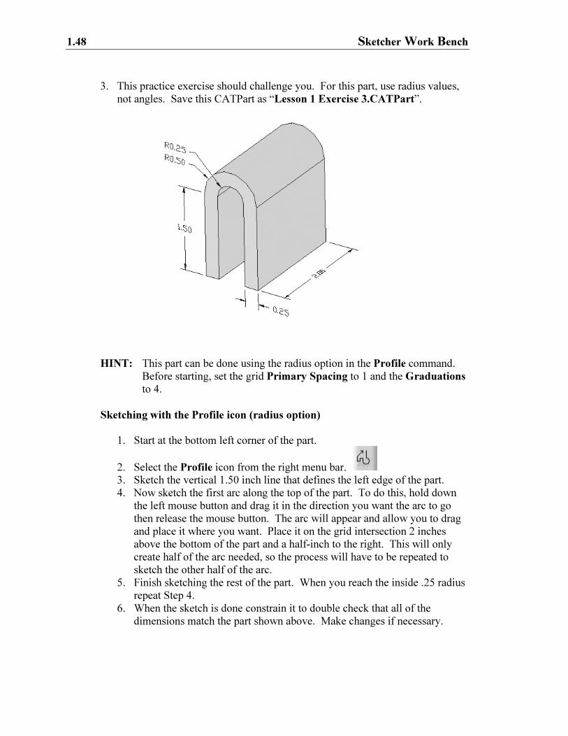
3. This practice exercise should challenge you. For this part, use radius values,
not angles. Save this CATPart as “Lesson 1 Exercise 3.CATPart”.
HINT: This part can be done using the radius option in the Profile command.
Before starting, set the grid Primary Spacing to 1 and the Graduations
to 4.
Sketching with the Profile icon (radius option)
1. Start at the bottom left corner of the part.
2. Select the Profile icon from the right menu bar.
3. Sketch the vertical 1.50 inch line that defines the left edge of the part.
4. Now sketch the first arc along the top of the part. To do this, hold down
the left mouse button and drag it in the direction you want the arc to go
then release the mouse button. The arc will appear and allow you to drag
and place it where you want. Place it on the grid intersection 2 inches
above the bottom of the part and a half-inch to the right. This will only
create half of the arc needed, so the process will have to be repeated to
sketch the other half of the arc.
5. Finish sketching the rest of the part. When you reach the inside .25 radius
repeat Step 4.
6. When the sketch is done constrain it to double check that all of the
dimensions match the part shown above. Make changes if necessary.
Creating A Simple Part 1.49
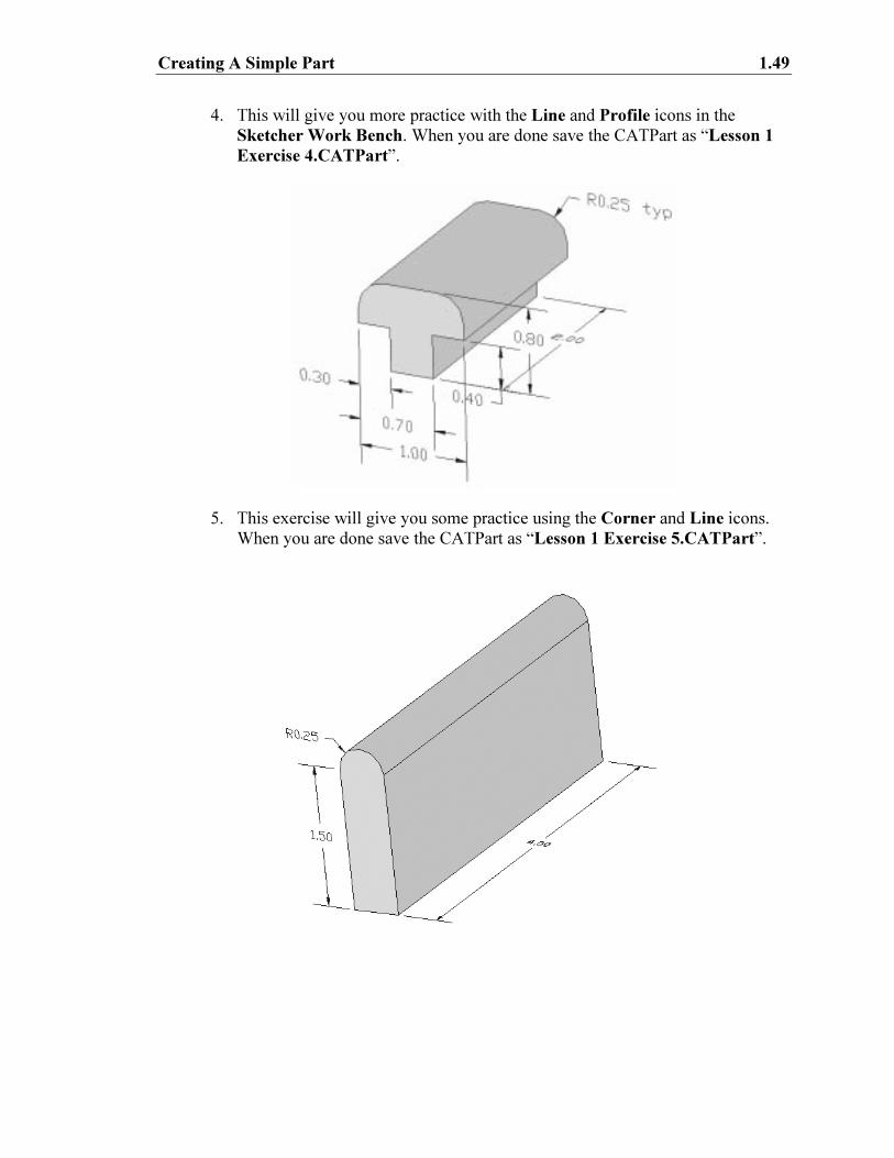
4. This will give you more practice with the Line and Profile icons in the
Sketcher Work Bench. When you are done save the CATPart as “Lesson 1
Exercise 4.CATPart”.
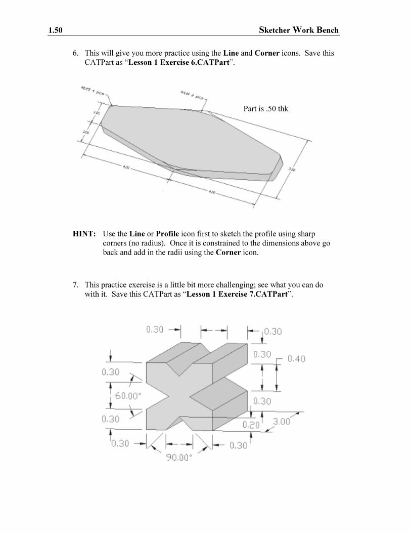
5. This exercise will give you some practice using the Corner and Line icons.
When you are done save the CATPart as “Lesson 1 Exercise 5.CATPart”.
1.50 Sketcher Work Bench
6. This will give you more practice using the Line and Corner icons. Save this
CATPart as “Lesson 1 Exercise 6.CATPart”.
HINT: Use the Line or Profile icon first to sketch the profile using sharp
corners (no radius). Once it is constrained to the dimensions above go
back and add in the radii using the Corner icon.
7. This practice exercise is a little bit more challenging; see what you can do
with it. Save this CATPart as “Lesson 1 Exercise 7.CATPart”.
Part is .50 thk

Creating A Simple Part 1.51
HINT: It is not as complicated as it looks. If your grid Graduations are set to
10, just snap to the intersections for the beginning and ending points of
your lines. To set the constraint for the angles select the angled lines
and the angle constraint will appear. Reference Step 19 for modifying
the angle value. If the profile gets over constrained, delete the Parallel
constraint.

1.52 Sketcher Work Bench
NOTES: