cavitational damage at francis turbine runnersciem.energ.pub.ro/2009/files/s7/s7_22.pdfcavitational...
TRANSCRIPT

U.P.B. Sci. Bull., Series …., Vol. ., No. …, 2009 ISSN 1454-23xx
CAVITATIONAL DAMAGE AT FRANCIS TURBINE
RUNNERS
Gheorghe BĂRAN1, Cătălin TILEA2, Gabriela OPRINA3, Florentina BUNEA4
On the basis of data from literature, laboratory researches and
measurements performed with a Francis runner having the rapidity ns of 200, the
values of the parameters indicating the intensity of cavitational damage are
analyzed. A method for predicting the cavitational damage is also proposed.
Keywords: cavitation, cavitational damage, Francis turbines
1. Introduction
The research concerning the cavitational damage started in 1921 (Föttinger) [1], had a “peak” between 60s and 70s and continues nowadays. In this research field in Romania PhD thesis [2-4] and books have been published [5-6], and solutions for diminishing the cavitational damage have been explored [7]. The new aspects of the cavitational damage treated in [8] show the complexity and the difficulty of the cavitation issue, which is often left to be solved in hydropower plants operation.
Generally, it is more or less explicitly assumed that the turbines operate with cavitation and there are regulations concerning guarantees for cavitational damage [9]. An important issue in turbine operation consist in predicting the intensity of the cavitational damage; this paper proposes a solution for this issue.
2. Parameters indicating the intensity of the cavitational damage
The intensity of the cavitational damage I and of erosion/scouring respectively is evaluated by the following parameters [6], [10]: - the ratio between the volume of the scoured material ∆V and the period of operation with cavitation τ
/vI v=� τ ; (1)
1 Prof., Hydraulic and Hydraulic Machineries Department, University “Politehnica” Bucharest, Romania, 2 PhD. Eng., Hidroelectrica, S.H. Târgu Jiu, Romania, 3,4 PhD. Eng., INCDIE ICPE-CA Bucharest, Romania.

Gh. Băran , C. Tilea, Gabriela Oprina, Florentina Bunea
- the mass of scoured material ∆m during the period τ
/mI m=� τ ; (2)
- the maximum depth of the scouring ∆h during the period τ
/hI h=� τ ; (3)
- the area ∆s scoured during the period τ
/sI s=� τ . (4)
When accurate information is lacking, all these overall parameters can be
used in the informative evaluation/prediction of the cavitation. A comparison among these parameters is shown in figure 1. The data are obtained on a Kaplan turbine after 7000 hours of operation; the runner diameter of the turbine is D1 = 4200 mm, the power is P = 57 MW, the head is 55 m and the speed is 187.5 rpm; the blades are made from stainless steel. With the reservation concerning the measurement of the cavitational damage depths accuracy (10-6 m), it is found that in the range (70÷100%)P the parameters Iv and Is have close values.
Fig. 1. The dependence of the cavitational damage of blades on power; 1- scoured volume, 2-
scoured area, 3- scour depth. [12, p. 224]
3. Laboratory researches
The mechanical resistance of different materials at cavitational damage is studied in laboratory. The equipments used for experiments have different working principles and consequently, the results that have been obtained are different (fig. 2).

Cavitational erosion at Francis turbine runners
Fig. 2. Characteristic curves of cavitational damage
The curves in figure 2 correspond to the equipments from table 1.
Table 1
Equipments for studying the cavitational damage
Current no.
Type of equipment Cavitational damage measurement Period of test
Scoured mass Scour depth
1. Ultrasound – Inch minutes 2. Hydrodynamic tunnel mg – hours 3. Magnetostriction mg – minutes 4. Jet mg – seconds
Table 2
The diameter and the maximum depth of the cavities
Steel mark
Period of test
(hours)
Stream velocity
(m/s)
Cavitation coefficient
σ
Diameter max-min
Maximum depth (mm)
Scoured volume (mm3)
FB-50AK 100 27.5 0.65 2-3 2.1 5.0 17-M13 100 27.5 0.65 2-3 2.0 4.7
OL38ABK 100 27.5 0.65 4 2.8 11.7
The experimental researches performed in a lab of Politehnica University
of Bucharest in a hydrodynamic tunnel show the evolution of the cavitational damage for three different types of steel (table 2 [6]).
The cavitation coefficient σ is computed with the relation given by Thoma
( )( ) 22 /am vp p t C v= − °σ ρ . (5)
The parameters mentioned in §2 can be computed with the values from table 2. It obtains:
Gh. Băran , C. Tilea, Gabriela Oprina, Florentina Bunea
( )
( )
2
2 3
2 2,8 10 mm/h
5 11,7 10 mm /h
h
v
I
I
−
−
= −
= −. (6)
For a test period of 60 hours (for a similar equipment) from figure 2 results a scoured material of about 60 mg; for m V∆ = ∆ρ and ρ = 8000 kg/m3 results the following parameter Iv
260 / 8000 60 1,25 10vI−= ⋅ = ⋅ mm3/h. (7)
This result is in a good agreement with the results computed previously.
4. Safety coefficients for cavitation
The cavitation coefficient of a hydropower plant is defined by the relation
( ){ }/inst at v sp p Hσ γ = − m , (8)
where atp is the atmospheric pressure, vp – vaporization pressure, gγ ρ= –
specific weight, sHm – suction height, H – head (at best efficiency point, BEP,
used in calculations); the atmospheric pressure varies with the altitude after the following relation
/ 10.33 / 900atp γ = − ∇ , (9)
wher ∇ is the level of water downstream the hydropower plant. The cavitation coefficient of turbine Tσ is obtained from laboratory tests
on model and is given by the relation (10)
1 2T mK K=σ σ (10)
where mσ is the value obtained on, K1 = 1,05÷1,10 is a coefficient for scale
correction and K2 = 1,2÷2,5 express the influence of the flowrate at other values than the best efficiency point [5].

Cavitational erosion at Francis turbine runners
Statistical formulae can be used for computing the coefficient Tσ ,
where ( )T sf nσ = , with ns the rapidity of turbine
5 1.416.065 10T sn−= ⋅σ (a)
( ) ( ){ }2 50.018 0.48 0.222 150 /100 exp0.07 0.0017 /100T s s sn n nσ = − − + + (b)
( ) ( )4 24 1.25 31.113 10 / 64 / 0.78 4 10 /100 0.03
T s s sn n n− −σ = × + + × + (c)
6 2 43.9 10 1.25 10 0.0265T s sn n
− −σ = ⋅ − ⋅ + (d)
( )20.043 /100T snσ = (e)
( )1.2830.0348 /100T snσ = (f)
Some laboratories/companies introduce safety coefficients for cavitation, such as:
/ ; /si inst Ti sx inst TxK K= =σ σσ σ σ σ , (11)
where siKσ represents the safety coefficient for incipient cavitation and sxKσ
corresponds to the flowrate Qx and depends on the material of the runner – for low alloy steel sxKσ = 2÷2.22 and for high alloy steel sxKσ = 1.1÷2 [5]. Values of
the cavitational damage depth for 4 types of runners are given in table 3 [5], [11-12].
Table 3
The depth of the cavitational damage (scour) for runners from steel 30L
Runner type Period of operation
[hours] Scour depth
[mm] Kσsx
Ih 104
[mm/h]
RO211 35000 2 2-3 0.57
RO123 11000 7 1.3 6.36 RO211 22000 30 1.15 13.63 RO82 5000 6 1.1 12
From table 3 it can be seen that for low safety coefficients (1.1÷1.15) the parameter Ih differs as order of magnitude in comparison with the case of high coefficients; concurrently, there is not a coherent relation between the parameter

Gh. Băran , C. Tilea, Gabriela Oprina, Florentina Bunea
Ih and the operation period of the turbine. In comparison with the values obtained in laboratory, the values of Ih from table 3 are different as order of magnitude.
5. Case study
During 2002 and 2008 operating repairs have been accomplished at a vertical Francis turbine having the characteristics shown in table 4.
Table 4
Technical characteristics of turbines
At best efficiency point, the rapidity is ns = 200. For a water level 470∇ =
m and Hs = -11.6 m σinst is given by the relation (12)
21.077 / 0.1158inst H= =σ . (12)
The coefficient Tσ is evaluated with a statistical formula selected among
the formulae presented above. Applying this formula for verifying Hs, values close to the ones from the project are obtained:
5 1.416.065 10 0.1158T sn−= ⋅ =σ . (13)
It results the safety coefficient at best efficiency point Ksn = 1.087 – a low value, considering that for Francis turbine sxKσ = 1.01÷1.6 [5, p. 412], so the
runner is exposed to cavitation. In the case of the analyzed turbine the following findings arose: - at the wicket gate were found small cavities, uniformly distributed on the lower camber of the blades (on the rings);
Label Measurement unit Value Turbine type – FVM 31.5 – 182 Net head max/min m 210/139 Head at BEP m 182 Flowrate at BEP m3/s 19.8 Suction height m -11.6 Characteristic diameter mm 1250 Revolution at BEP rot/min 750 Power at BEP KW 31500 Number of runner blades – 14 Number of guide vanes – 16 Height of wicket gates mm 250
Cavitational erosion at Francis turbine runners
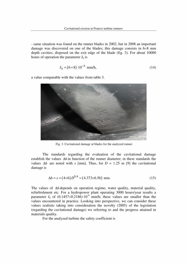
- same situation was found on the runner blades in 2002, but in 2008 an important damage was discovered on one of the blades; this damage consists in 6÷8 mm depth cavities, disposed on the exit edge of the blade (fig. 3). For about 10000 hours of operation the parameter Ih is
( ) 46 8 10hI−= ÷ ⋅ mm/h, (14)
a value comparable with the values from table 3.
Fig. 3. Cavitational damage at blades for the analyzed runner
The standards regarding the evaluation of the cavitational damage establish the values h∆ in function of the runner diameter; in these standards the values h∆ are noted with s [mm]. Thus, for D = 1.25 m [9] the cavitational damage is
( ) ( )0.44÷6 4.373÷6.56h s D∆ = = = mm. (15)
The values of h∆ depends on operation regime, water quality, material quality, refurbishment etc. For a hydropower plant operating 3000 hours/year results a parameter Ih of (0.1457÷0.2186)·10-4 mm/h; these values are smaller than the values encountered in practice. Looking into perspective, we can consider these values realistic taking into consideration the novelty (2005) of the legislation (regarding the cavitational damage) we referring to and the progress attained in materials quality. For the analyzed turbine the safety coefficient is
Gh. Băran , C. Tilea, Gabriela Oprina, Florentina Bunea
( )0.76251.41
5 1/ 2 5.40.705
21.0771/ 0.065 10 / 30.7inst
s x
Tx
HK n P H
H Pσ
σ
σ
− = = ⋅ ⋅ = . (16)
Knowing the head and the power of the turbine and using the data from table 3, the operation regime in cavitation can be determined.
6. Conclusions
1. The analysis of the data from literature concerning the cavitational damage at Francis runners showed that the main factor determining the intensity of the damage is the safety coefficient Ksσx. 2. For the case study analyzed in this paper the safety coefficient is given by relation (16).
3. In order to roughly predict the evolution of the damage, the following stages are proposed in this paper: - damage can be neglected for Ih < 0.5·10-4 mm/h; - low damage for Ih = (0.5÷1.5)·10-4 mm/h; - average damage for Ih = (2÷8-9)·10-4 mm/h; - heavy damage for Ih > 10-4 mm/h.
R E F E R E N C E S
[1] R. Knapp, J. Daily, F. Hammit, Cavitation, Mc Graw Hill, New York, 1970. [2] Gh. Băran, Teză de doctorat, I.P.B., 1976. [3] I. Bordeaşu, Teză de doctorat, Universitatea Politehnica Timişoara, 1997. [4] L. Ciocan, Teză de doctorat, Insitutul Politehnic Iaşi, 1985. [5] I. Anton, Cavitaţia (Cavitation), V. II, Ed. Academiei, Bucureşti, 1985. [6] Gh. Băran, A. Ciocănea, Curgeri cavitaţionale şi abrazive (Cavitational and abrasive flows), Ed. Printech, Buc., 2005, ISBN 973-718-267-7. [7] *** Studiu privind reducerea cavitaţiei la rotoarele HA de la CHE Motru (Study regarding the diminishing of the cavitation at the turbine runners from Motru Hydropower Plant), ICEMENERG-UPB, 2003. [8] S.C. Li, A New Type Of Cavitation (Damage) Identified From Three Gorges Turbines, IAHR 24th Symposium On Hydraulic Machinery And Systems, October 27-31 2008, Brasil, paper 06. [9] SR EN 60.609-1, Evaluarea eroziunii datorită cavitaţiei la turbine, pompe de acumulare şi turbine-pompe (The evaluation of the erosion due to cavitation at turbines, accumulation pumps and turbines-pumps), P. I, dec. 2005, Ed. 1. [10] J.M. Darcy, A. Verry, P. Grison, Une meilleure maitrise de la cavitation, Épure, no. 25, Electricité de France, pp. 13-21, 1990 [11] V.I. Karelin, Iznos lopastnîh ghidravliceskih mesin ot cavitatii i nanosov, Izd. Masinostroenie, Moskva, 1970. [12] N.I. Pîlaev, I.U. Edeli, Kavitatia v ghidroturbina Izd. Masinostroenia, Leningrad, 1974.