caxperts 3d symboldesigner symboldesigner/manual... · caxperts 3d symboldesigner - august 2019 4...
TRANSCRIPT

3D SymbolDesigner
Manual

Copyright
Copyright © 2019 CAXperts GmbH. All Rights Reserved.
Including software, file formats, and audio-visual displays; may be used pursuant to applicable
software licence agreement; contains confidential and proprietary information of CAXperts and/or
third parties which is protected by copyright law, trade secret law, and international treaty, and may
not be provided or otherwise made available without proper authorisation.
Restricted Rights Legend
Rights reserved under the copyright laws of the Federal Republic of Germany.
Warranties and Liabilities
All warranties given by CAXperts about equipment or software are set forth in your purchase contract,
and nothing stated in, or implied by, this document or its contents shall be considered or deemed a
modification or amendment of such warranties. CAXperts believes the information in this publication
is accurate as of its publication date.
The information and the software discussed in this document are subject to change without notice
and are subject to applicable technical product descriptions. CAXperts is not responsible for any error
that may appear in this document.
The software discussed in this document is furnished under a licence and may be used or copied only
in accordance with the terms of this licence. THE USER OF THE SOFTWARE IS EXPECTED TO MAKE
THE FINAL EVALUATION AS TO THE USEFULNESS OF THE SOFTWARE IN HIS OWN ENVIRONMENT.
Trademarks
CAXperts is a registered trademark of CAXperts GmbH. Intergraph, the Intergraph logo, SmartSketch,
FrameWorks, SmartPlant, INtools, MARIAN, PDS, IGDS, RIS and IntelliShip are registered trademarks
of Intergraph Corporation. IGDS file formats ©1987-1994 Intergraph Corporation. Microsoft and
Windows are registered trademarks of Microsoft Corporation. Bentley, the Bentley logo “B,” and
MicroStation are registered trademarks of Bentley Systems, Inc. ISOGEN is a registered trademark of
Alias Limited. Other brands and product names are trademarks of their respective owners.

Table of Contents
I. Introduction ........................................................................................... 4
II. Installation ............................................................................................. 4
Setup
Licence
III. 3D SymbolDesigner ............................................................................... 8
Basic tutorial: tank with nozzles
Custom forms
Second tutorial: a simple custom instrument (piping)
Third tutorial: a piping spec part
On-the-fly and stock parts
IV. Appendix (Graphical User Interface) .................................................... 30
File
Project
Edit
Tree context menu
View
Options
Licence
Help
V. Appendix .............................................................................................. 52
Angles
Intrinsic math functions
Derived math functions
Naming rules
.NET symbols
VI. Appendix: Piping nozzles ..................................................................... 56
PipingGenericDataBolted
PipingGenericDataFemale
PlainPipingGenericData
PipingGenericDataMechanical
Port Attributes SymbolDesigner
VII. Contact ................................................................................................ 63

Helpdesk

CAXPERTS 3D SYMBOLDESIGNER - AUGUST 2019 4
Introduction
3D SymbolDesigner enables customers to graphically author their symbols for plant design software
like Intergraph® SmartPlant® 3D without programming knowledge. 3D SymbolDesigner is designed to
meet customer needs in symbol development activities including an interactive graphical design
environment, import functionality from sources like Microstation DGN files and export to a variety of
data formats (e.g. Visual Basic projects and Excel bulk load sheets for Intergraph SmartPlant 3D). 3D
SymbolDesigner is based on an open, scalable architecture. Symbol data and symbol variants are
stored in Excel files and can be edited with Microsoft® Office or external automation software.
Installation
Setup
Requirements:
▪ Supported operating systems:
▪ Microsoft Windows XP
▪ Microsoft Windows Server 2003
▪ Microsoft Windows Vista
▪ Microsoft Windows 7 or later
▪ Microsoft Office XP, 2003, 2007 or 2010 (32-bit only)
▪ Microsoft .NET Framework 3.5
▪ Microsoft Visual Basic 98 or Visual Basic 2010 and higher
Optional:
▪ Intergraph Smart 3D (to compile .NET symbols Smart 3D 2014.R1 or higher is
needed)
Administrator rights are required on each computer to install CAXperts 3D SymbolDesigner. “Run as”
is not supported.
Uninstall
To uninstall the software, select Control panel from the start menu. Then on
• Windows 7-10: in large or small icon view, click Programs and features. If you're
using category view, under Programs, click Uninstall a program.
• Windows Vista: in classic view, double-click Programs and features. In control
panel home view, under Programs, click Uninstall a program.
• Windows XP/2000: (Double) click the Add or remove programs icon.
Select the program you want to remove, and click Uninstall/Remove. Alternatively, right-click the
program and select Uninstall.
Setup command line (for administrators)
The following command line options are supported by the installer:
CAXPERTS 3D SYMBOLDESIGNER - AUGUST 2019 5
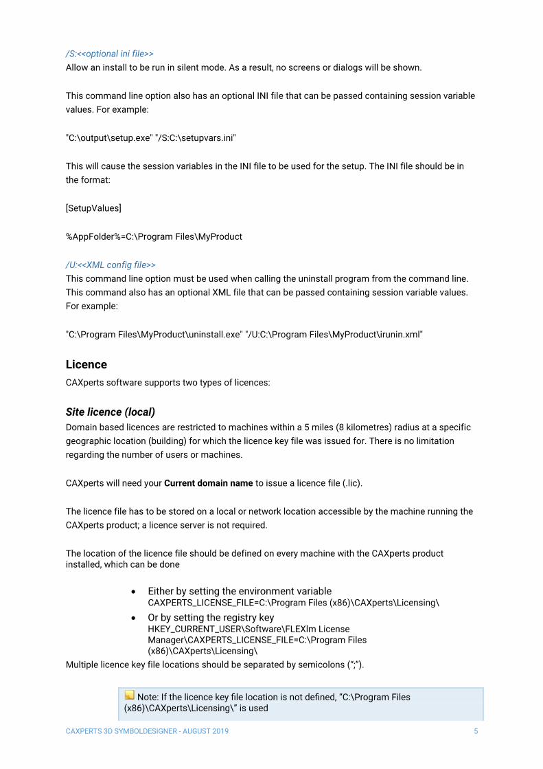
/S:<<optional ini file>>
Allow an install to be run in silent mode. As a result, no screens or dialogs will be shown.
This command line option also has an optional INI file that can be passed containing session variable
values. For example:
"C:\output\setup.exe" "/S:C:\setupvars.ini"
This will cause the session variables in the INI file to be used for the setup. The INI file should be in
the format:
[SetupValues]
%AppFolder%=C:\Program Files\MyProduct
/U:<<XML config file>>
This command line option must be used when calling the uninstall program from the command line.
This command also has an optional XML file that can be passed containing session variable values.
For example:
"C:\Program Files\MyProduct\uninstall.exe" "/U:C:\Program Files\MyProduct\irunin.xml"
Licence
CAXperts software supports two types of licences:
Site licence (local)
Domain based licences are restricted to machines within a 5 miles (8 kilometres) radius at a specific
geographic location (building) for which the licence key file was issued for. There is no limitation
regarding the number of users or machines.
CAXperts will need your Current domain name to issue a licence file (.lic).
The licence file has to be stored on a local or network location accessible by the machine running the
CAXperts product; a licence server is not required.
The location of the licence file should be defined on every machine with the CAXperts product installed, which can be done
• Either by setting the environment variable CAXPERTS_LICENSE_FILE=C:\Program Files (x86)\CAXperts\Licensing\
• Or by setting the registry key HKEY_CURRENT_USER\Software\FLEXlm License Manager\CAXPERTS_LICENSE_FILE=C:\Program Files (x86)\CAXperts\Licensing\
Multiple licence key file locations should be separated by semicolons (“;”).
Note: If the licence key file location is not defined, “C:\Program Files (x86)\CAXperts\Licensing\” is used

CAXPERTS 3D SYMBOLDESIGNER - AUGUST 2019 6
Note: The licence key file may be renamed (including the extension). The CAXperts product will check the content of all files in the licence folder(s) for valid keys.
Note: Changes to the key path (in the environment variable or registry key) are read during the next start of the CAXperts product.
Floating (server) licence
Floating licences require a FlexNET server (lmadmin or lmgrd) accessible by the machine running the
CAXperts product. The licence key file is typically located on the FlexNET server machine. The licence
key file defines the maximum number of seats which can be used at the same time.
Every running instance of the CAXperts software product will require one seat, no matter if the application is
running multiple times on the same or different machine(s).
New instances can only be started as long as seats are available and the FlexNET server is accessible.
The location of the licence server must be defined on every machine with the CAXperts product installed, which can be done
• Either by setting the environment variable CAXPERTS_LICENSE_FILE=@YourServerName
• Or by setting the registry key HKEY_CURRENT_USER\Software\FLEXlm License Manager\CAXPERTS_LICENSE_FILE=@YourServerName
Every computer name must be preceded by the @ symbol. Multiple licence server locations should be
separated by semicolons (“;”).
YourServerName is the Windows computer name of the machine running lmadmin (FlexNET server).
If lmadmin is running on a non-default port, the port number should be defined like this: port@
YourServerName.
Note: Changes to the server path (in the environment variable or registry key) are read during the next start of the CAXperts product.
Borrowed licences
Licence seats can be borrowed for a period of time from the server and saved to the local machine.
Once the seat has been borrowed the CAXperts application can be used without any connection to the
FlexNET server.

CAXPERTS 3D SYMBOLDESIGNER - AUGUST 2019 7
To borrow a licence seat press the Borrow seat button, define the loan period (up to 7 days) and press
OK. When the borrowed seat expires it gets automatically returned back to the FlexNET server.
The seat can be returned earlier by pressing the Return borrowed seat button.
Note: Without a valid licence file the software will run in demo mode.

CAXPERTS 3D SYMBOLDESIGNER - AUGUST 2019 8
3D SymbolDesigner
3D SymbolDesigner is a high-level symbol definition modeller. Graphical primitives may be
parameterised; dimensions, position and rotation in space can be defined by formulas. 3D
SymbolDesigner is case-sensitive, so be careful when typing names and formulas. All symbol data
are stored in XML-structures which may also be exported.
Users may also define several variants of a symbol which can be stored in an Excel file together with
the symbol geometry.
We recommend the user to read the tank-with-nozzles tutorial first even if he or she intends to build
symbols for other disciplines.
Note – attributes and their interfaces are stored in Config.xls in the data subdirectory of your 3D SymbolDesigner installation. Add parameters that are not already included at the end of the Attributes tab of Config.xls. 3D SymbolDesigner will check the parameter mapping (last line in the table of variants) against these attributes and will mark all spelling errors and missing attributes with red background.
Sample 3D SymbolDesigner projects can be found in the Samples sub-folder of your 3D
SymbolDesigner program folder. These projects are included:
Project Discipline Level Remarks
Angle Piping (spec) *** Includes manually created bulkload sheet examples
Compensator Piping (spec) **** No bulkload sheets available
CustomInstrument Piping (custom
instruments)
** Sample bulkload sheets will be created by 3D
SymbolDesigner (custom instrument tutorial)
GateValveHandWheel Piping (spec) *** Contains two projects, sample bulkload sheets included
Tank Equipment * Sample bulkload sheets will be created by 3D
SymbolDesigner (basic tutorial)
Tee Piping (spec) *** Includes manually created bulkload sheet examples and
a SymbolIcon
Basic tutorial: tank with nozzles
This tutorial explains how to build and bulkload a storage tank symbol for SmartPlant 3D.
1. Find out which parameter names you need to parameterise the symbol in SmartPlant 3D. Standard names may be found on the CustomInterfaces tab of C:\Program Files\SmartPlant\3D\CatalogData\BulkLoad\Datafiles\Equipment.xls. You will find
CAXPERTS 3D SYMBOLDESIGNER - AUGUST 2019 9
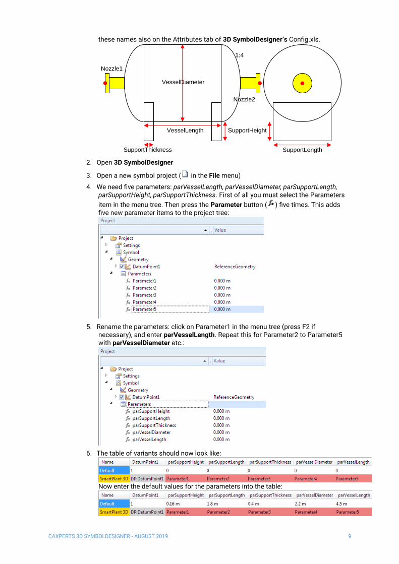
these names also on the Attributes tab of 3D SymbolDesigner’s Config.xls.
2. Open 3D SymbolDesigner
3. Open a new symbol project ( in the File menu)
4. We need five parameters: parVesselLength, parVesselDiameter, parSupportLength, parSupportHeight, parSupportThickness. First of all you must select the Parameters
item in the menu tree. Then press the Parameter button ( ) five times. This adds five new parameter items to the project tree:
5. Rename the parameters: click on Parameter1 in the menu tree (press F2 if necessary), and enter parVesselLength. Repeat this for Parameter2 to Parameter5 with parVesselDiameter etc.:
6. The table of variants should now look like:
Now enter the default values for the parameters into the table:
VesselLength
VesselDiameter
Nozzle1
Nozzle2
SupportThickness
SupportHeight
SupportLength
1:4

CAXPERTS 3D SYMBOLDESIGNER - AUGUST 2019 10
7. Rename the “Default” variant and rename the SmartPlant 3D parameter mappings: select the Parameter1 cell and click the right mouse button. In the context menu select the Set SmartPlant 3D attribute. Choose the right attribute in the list box, check the Occurrence attribute and press the Apply button (add OA: in front of the parameter name, if the parameter is an occurrence attribute, i.e. an attribute which may be modified at runtime in SmartPlant 3D). Repeat this for Parameter2 to Parameter5. 3D SymbolDesigner checks the spelling.
8. The parameters now are valid and the background colour turned to green:
9. Select the Project.Symbol.Parameters node and click twice on the Add piping port
(bolted preset) toolbar icon ( ) to add two pipe ports and twice on the Add piping
connector button ( ) to add two nozzles.
10. Click twice on the Spherical Segment button ( ), once on the Cylinder button ( )
and twice on the Box button ( ) to add the primitives for the tank geometry. The symbol tree should now look like:
CAXPERTS 3D SYMBOLDESIGNER - AUGUST 2019 11
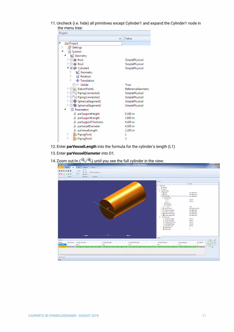
11. Uncheck (i.e. hide) all primitives except Cylinder1 and expand the Cylinder1 node in the menu tree:
12. Enter parVesselLength into the formula for the cylinder’s length (L1)
13. Enter parVesselDiameter into D1.
14. Zoom out/in ( / ) until you see the full cylinder in the view:

CAXPERTS 3D SYMBOLDESIGNER - AUGUST 2019 12
15. Check SphericalSegment1 and enter 180 deg or 180° into the formula of Rotation.Z: The semisphere is now visible on the left side of the cylinder:
16. Enter parVesselDiameter into Geometry.D1 and parVesselDiameter / 4 into Geometry.R1:
17. Switch to wireframe mode ( ) and tick the SphericalSegment2 node, enter parVesselDiameter into Geometry.D1, parVesselDiameter / 4 into Geometry.R1 and

CAXPERTS 3D SYMBOLDESIGNER - AUGUST 2019 13
parVesselLength into Translation.X of SphericalSegment2:
18. Tick the Box1 and Box2 nodes and enter parSupportThickness into Geometry.L1 and parSupportLength into Geometry.L3 of both boxes. The supports should reach into the tank, so the formula for Geometry.L2 of both boxes is parVesselDiameter / 4 + parSupportHeight.
19. The formula for Translation.Z of both boxes is - 3 * parVesselDiameter / 8 - parSupportHeight / 2
20. Enter parVesselLength into Translation.X of Box2 to translate the box
21. Rotate Box2 by entering 180 deg into its Rotation.Z
22. Tick PipingConnector1 and PipingConnector2. Rotate PipingConnector1 by entering 180 deg into its Rotation.Z
23. Enter - parVesselDiameter / 2 into Translation.X of PipingConnector1
24. Enter parVesselLength + parVesselDiameter / 2 into Translation.X of PipingConnector2
25. Set Geometry.L1 of PipingConnector1 and PipingConnector2 to parVesselDiameter / 2

CAXPERTS 3D SYMBOLDESIGNER - AUGUST 2019 14
26. The modelling of the tank symbol is now finished:
27. Press the toolbar button ( ) to export the symbol to SmartPlant 3D.
28. Select the parent node of the new symbol in the catalogue tree view on the first tab (if you see only a node named “Catalogue”, double click it to open the tree). Press the Add button:

CAXPERTS 3D SYMBOLDESIGNER - AUGUST 2019 15
29. Select the new node and enter the name in the Catalogue node column and description of the new symbol class in the Key column (e.g. HorizontalTank):
30. Keep this item selected and click on the Build tab:
31. Click Browse… to select a target folder for the Visual Basic Project and the bulkload sheet.
32. Uncheck all items on the Compiler settings frame.
33. When Visual Basic 6 is installed on your machine: Tick Compile project.

CAXPERTS 3D SYMBOLDESIGNER - AUGUST 2019 16
34. Click on the Start button. Before the export starts, 3D SymbolDesigner checks if the
parameters and the used variant names are valid (see 0 Naming rules). This will avoid
afterwards errors during the bulkload process. The occurred errors are shown in the
Error list tab. By pressing an item of the list the cursor will move to the corresponding
cell in the table.
35. Optionally: Export of a 3D PDF datasheet (see: Export of a 3D PDF datasheet)
36. Press OK to close the SmartPlant 3D Wizard window. Now you may close the CAXperts 3D SymbolDesigner program.
37. If Visual Basic or Visual Basic .NET was not available: Please compile the resulting Visual Basic project on a machine where Visual Basic is installed and “register” the DLL on the target system.
38. Save and bulkload the Excel file using the append mode of the Bulkload tool provided with SmartPlant 3D:

CAXPERTS 3D SYMBOLDESIGNER - AUGUST 2019 17
39. After the bulkload the new symbol is available in the catalogue of SmartPlant 3D:
40. After placement, the symbol looks like:

CAXPERTS 3D SYMBOLDESIGNER - AUGUST 2019 18
Custom forms
Since version 07.00.1602.1704 3D SymbolDesigner creates a form definition project template in the
export folder of the symbol. The solution/project file can be opened, modified and compiled with the
current version of Microsoft C#.
The template lists all available attributes in text/drop-down boxes:
Use the form editing functions of Visual Studio to modify the template, e.g. replace the background
image, rearrange the input boxes or change the font size:
Build the DLL in Visual Studio, put it on the symbol share and run Update Custom Symbol
Configuration in the Smart 3D Project Management.

CAXPERTS 3D SYMBOLDESIGNER - AUGUST 2019 19
Use the attribute FormDefinition on the bulkload file of the symbol to assign the form to the symbol. If
the bulkload was successful, the custom form ( ) can be used in Smart 3D:
Second tutorial: a simple custom instrument (piping)
Please read the tank tutorial first to learn and understand the basic functions of 3D SymbolDesigner,
especially how to add, rename and edit nodes.
In this tutorial we will build a custom instrument part with two nozzles, a handwheel and insulation for
the body part and the nozzles.
Note - piping symbols are using a right-handed coordinate system with y-axis up in SmartPlant 3D
(there are exceptions from this rule: three-way-valves with integral operator).
Create a new project
1. Click to create a new symbol project.
2. Change the coordinate system orientation by pressing the Y-Axis up button ( ).

CAXPERTS 3D SYMBOLDESIGNER - AUGUST 2019 20
Add parameters
3. Select the Parameters item in the menu tree. Then click five times on the parameter
button ( ).
4. Rename the parameters: click on Parameter1 (press F2 if needed) and enter parFacetoFace. Repeat this for Parameter2 to Parameter5 with parActuatorHeight, parActuatorDiameter, parStemWidth and parInsulationThickness.
5. The table of variants should now look like:
6. Enter now the default values for the parameters into the table:
7. Rename the variant Default to MyCustomInstrument:
8. Rename the SmartPlant 3D parameter mappings: select the Parameter1 cell and click right mouse button. In the context menu select the Set SmartPlant 3D attribute. Choose the right attribute in the list box, check the Occurrence attribute and press the Apply button (add OA: in front of the parameter name, if the parameter is an occurrence attribute, i.e. an attribute which may be modified at runtime in SmartPlant 3D). Repeat this for Parameter2 to Parameter5. 3D SymbolDesigner checks the spelling. The parameters are now valid and the background colour turned to green:

CAXPERTS 3D SYMBOLDESIGNER - AUGUST 2019 21
Add PipingPorts
9. Expand the PipingPort parameter collection toolbar icon ( ) and click the piping port (bolted preset). One PipingPort will be added to the treeview and the list of variants. Repeat the step once again to add a second one.
Add nozzles
10. Click twice on the button for piping connectors ( ). Press F2 to rename the first nozzle node to VNoz1 and the second one to VNoz2.
11. Rotate VNoz1 by 180 deg about the z axis.
12. Move VNoz1 to the one end of the instrument by typing the following into its Translation.X subnode: - parFacetoFace / 2 - PipingPort1.FlangeProjectionOrSocketOffset + PipingPort1.FlangeProjection + PipingPort1.SeatingOrGrooveOrSocketDepth
13. Move VNoz2 to the other end of the instrument by typing the following into its Translation.X subnode:

CAXPERTS 3D SYMBOLDESIGNER - AUGUST 2019 22
parFacetoFace / 2 + PipingPort2.FlangeProjectionOrSocketOffset - PipingPort2.FlangeProjection - PipingPort2.SeatingOrGrooveOrSocketDepth
Add graphical primitives
14. Click twice on the cone button ( ), once on sphere ( ), once on torus ( ) and four
times on cylinder ( ).
15. Rename Cone1 to Body1, Cone2 to Body2, Sphere1 to Body3, Torus1 to HandWheel, Cylinder1 to Stem, Cylinder2 to InsBody, Cylinder3 to InsCylinderVNoz1 and Cylinder4 to InsCylinderVNoz2.
16. Right click on the InsBody node, select properties from the context menu and change the aspect from SimplePhysical to Insulation. Repeat this for InsCylinderVNoz1 and InsCylinderVNoz2.

CAXPERTS 3D SYMBOLDESIGNER - AUGUST 2019 23
17. Unselect all created primitives, except Body1 and Body2, using the checkbox in front of them.
18. Change to S/E isometric view as shown on the picture below.
Parameterise the primitives
19. Expand the Body1 node and the Geometry subnode and type in the following formula as value for the cone’s length (L1) property: parFacetoFace / 2 - PipingPort1.FlangeOrHubThickness - PipingPort1.FlangeProjection
20. Change the value of the cone’s first diameter (D1) of the same node to 0.001. The value of a distance must not be zero, because SmartPlant 3D is not able to handle zero-distance values.
21. Type in the following as value for the D2 property: PipingPort1.PipingOutsideDiameter
22. Expand the Body2 and underlying Geometry node and set the value of L1 to: parFacetoFace / 2 - PipingPort2.FlangeOrHubThickness - PipingPort2.FlangeProjection
23. Change the value of D1 to 0.001.
24. Set the value of the cone’s second diameter (D2) to PipingPort2.PipingOutsideDiameter.
25. Rotate Body2 by typing 180 deg into its Rotation.Z property.

CAXPERTS 3D SYMBOLDESIGNER - AUGUST 2019 24
26. Use the zoom-in tool ( ) until the two cones fit to the view. Now it looks like this:
27. Expand the Body3 and the appropriate Geometry subnode to change the diameter value (D1) to the average outside diameter of the pipe by typing: (PipingPort1.PipingOutsideDiameter + PipingPort2.PipingOutsideDiameter ) / 2
28. Change the L1 value of the Stem primitive to parActuatorHeight.
29. Set the Stem’s diameter (D1) to parStemWidth.
30. Rotate the Stem by assigning 90 deg to its Rotation.Z property.
31. Change the Value of the Handwheel’s D1 property to parStemWidth.
32. Type in the formula (parActuatorDiameter - parStemWidth) / 2 for the Handwheel’s radius (R1).
33. Set its angle (A1) property to 360 deg.
34. Expand the Handwheel’s Rotation subnode and set X to 90 deg.
35. Open the Translation branch and type in parActuatorHeight - parStemWidth / 2 for the Y value.
36. Set Z to -Geometry.HandWheel.Geometry.R1.
37. Switch on the checkboxes of Body3, Handwheel and Stem and zoom out until the instrument fits to the viewport.

CAXPERTS 3D SYMBOLDESIGNER - AUGUST 2019 25
Now you should see something like that:
38. Expand InsBody and its subnode Geometry to set its length L1 to: Geometry.Body1.Geometry.L1 + Geometry.Body2.Geometry.L1
39. Assign the formula Max(Geometry.Body1.Geometry.D1, Geometry.Body2.Geometry.D1) + 2 * parInsulationThickness to its D1 property.
40. Expand the Translation subnode and set X to -Geometry.Body1.Geometry.L1.
41. Change to the InsCylinderVNoz1 primitive and expand its subnode Geometry. Change the value of L1 to PipingPort1.FlangeOrHubThickness + parInsulationThickness.
42. Type the formula PipingPort1.FlangeOrHubOutsideDiameter + 2 * parInsulationThickness in D1.
43. Move this cylinder by changing its Translation.X property to -parFacetoFace / 2 + PipingPort1.FlangeProjection.
44. Expand the branch InsCylinderVNoz2 and the underlying Geometry node. Assign the formula PipingPort2.FlangeOrHubThickness + parInsulationThickness to the L1 value.
45. Set PipingPort2.FlangeOrHubOutsideDiameter + 2 * parInsulationThickness for the D1 property.
46. Move the cylinder by setting Geometry.Body2.Geometry.L1 - parInsulationThickness for X.

CAXPERTS 3D SYMBOLDESIGNER - AUGUST 2019 26
47. Tick all the remaining unchecked primitives. Now the viewport should look like this:
Export to SmartPlant 3D
48. The symbol is now ready to be exported to SmartPlant 3D. Save it first, and then click
the toolbar button to export it.
49. Optionally: Press the Reload Button. The catalogue structure will be loaded from the SP3D database. This will only work if a valid SP3D database server is available and configured (see item 52).
50. Add a new node below the Catalogue-Piping-Custom Instruments node, select it, give it a decent key and description and select it again.
51. On the second tab (Build) choose your target directory. You also may tick the checkbox Compile project below the Compiler settings topic. This will only work if the necessary SP3D libraries (dll) are registered and VisualBasic 6 is installed on this machine.
52. Click on the Start button. Before the export starts, the 3D SymbolDesigner checks if the parameters and the used variant names are valid (see 0 Naming rules). This will avoid afterwards errors during the bulkload process. The occurred errors are shown in the Error list tab. By pressing an item of the list the cursor will move to the corresponding cell in the table.
53. Optionally: Export of a 3D PDF datasheet (see: Export of a 3D PDF datasheet)
CAXPERTS 3D SYMBOLDESIGNER - AUGUST 2019 27
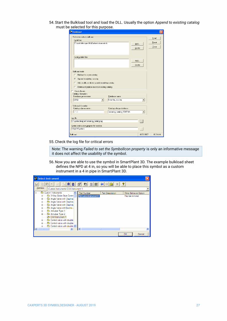
54. Start the Bulkload tool and load the DLL. Usually the option Append to existing catalog must be selected for this purpose.
55. Check the log file for critical errors
Note: The warning Failed to set the SymbolIcon property is only an informative message it does not affect the usability of the symbol.
56. Now you are able to use the symbol in SmartPlant 3D. The example bulkload sheet defines the NPD at 4 in, so you will be able to place this symbol as a custom instrument in a 4 in pipe in SmartPlant 3D.
CAXPERTS 3D SYMBOLDESIGNER - AUGUST 2019 28
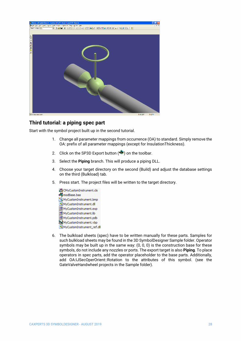
Third tutorial: a piping spec part
Start with the symbol project built up in the second tutorial.
1. Change all parameter mappings from occurrence (OA) to standard. Simply remove the OA: prefix of all parameter mappings (except for InsulationThickness).
2. Click on the SP3D Export button ( ) on the toolbar.
3. Select the Piping branch. This will produce a piping DLL.
4. Choose your target directory on the second (Build) and adjust the database settings on the third (Bulkload) tab.
5. Press start. The project files will be written to the target directory.
6. The bulkload sheets (spec) have to be written manually for these parts. Samples for such bulkload sheets may be found in the 3D SymbolDesigner Sample folder. Operator symbols may be built up in the same way: (0, 0, 0) is the construction base for these symbols, do not include any nozzles or ports. The export target is also Piping. To place operators in spec parts, add the operator placeholder to the base parts. Additionally, add OA:IJSecOperOrient::Rotation to the attributes of this symbol. (see the GateValveHandwheel projects in the Sample folder).

CAXPERTS 3D SYMBOLDESIGNER - AUGUST 2019 29
7. Bulkload the part as described in chapter 3.2, item 54 and the following.
On-the-fly and stock parts
1. On-the-fly parts need ports that can be modified by the user after placement. The second tutorial (see above) shows how to create a piping instrument with these ports by adding a new sub-node to the “Custom Instruments” or “Custom Specialties” node.
2. All non-on-the-fly-parts (=stock) have to be exported by selecting the “Piping” node directly. This is valid for typical spec parts, operators, clamps and stock instrument class data and stock piping speciality class data (e.g. see already existing data in 'InstrumentClassData' and 'PipingSpecialtyClassData' sheets).
Note: you have to adapt the generated bulkload workbook after the 3D SymbolDesigner export. E.g. 'PipeComponentClass' has to be replaced by 'SpecialtyClass' in the header of the part class sheet.

CAXPERTS 3D SYMBOLDESIGNER - AUGUST 2019 30
Appendix (Graphical User Interface)
File
New
New ( ) creates a new 3D SymbolDesigner symbol project.
Open
Open ( ) shows a file open dialogue. 3D SymbolDesigner supports 3D SymbolDesigner project files
(.xlsx and .xls, Microsoft Excel files with symbol geometry data and variants; .xml 3D SymbolDesigner
XML symbol geometry data).
Save
Save ( ) stores the content of the active form. If the file name is unknown, a Save As dialogue is
shown.
Save as
Save as opens a Save As dialogue where the filename to save the content of the active form to can be
chosen.
Export to SmartPlant 3D
Export to SmartPlant 3D ( ) shows a configuration dialogue (SmartPlant 3D Wizard) for the export
to Intergraph SmartPlant 3D.
The dialogue shows two tabs for configuring the export to SmartPlant 3D.
Under ideal conditions, the Wizard will produce a Visual Basic project containing the symbol
geometry, compile it, register the DLL, produce an Excel file for the catalogue bulk load and start the
bulk load to the catalogue.
The Symbol tab provides a catalogue tree to select the target position in the SmartPlant 3D
catalogue.

CAXPERTS 3D SYMBOLDESIGNER - AUGUST 2019 31
Discipline Bulkload sheet
Equipment Add/select a folder below Equipment
Add/select a node below this folder
✓
Equipment component Add/select a folder below Equipment
Components
Add/select a node below this folder
✓
Piping spec symbol Select Piping -
Piping custom instrument Add/select a node below Piping-
Custom Instruments
✓
Piping custom specialty Add/select a node below Piping-
Custom Specialties
✓
Hangers and supports Select Supports -
When the Piping or Supports node is selected, 3D SymbolDesigner will produce a Visual Basic
project/DLL for a piping symbol (but no Excel bulk load file).
Note – A file called ComponentTree.xml is parsed in for this dialogue, which is generated by the Reload button and may be modified manually to represent the catalogue tree of the target system.
The third column shows the PartClassType of the symbol. If none is selected, 3D SymbolDesigner will assume that the type is PipeComponentClass.
The checkbox Write full hierarchy allows the user in the case of a re-export to export the full R-
Hierarchy in the bulkload file. Otherwise a re-export produces an empty R-Hierarchy sheet.
The Build tab shows the project settings from the project tree view and allows the configuration of the
Visual Basic code output and compilation.
• Export details: this setting is useful for the measuring operations in SmartPlant 3D afterwards. With additional edges & points the measuring operations in the older versions of SmartPlant 3D are much easier. The standard value is Faces.
• Error logging: the log file goes here.
• Project target folder: the Visual Basic code goes here
• Output format: VB6 code or VB.NET (ALPHA, non-production use only)
• Make DLL binary compatible: Recommended to be switched on, when the Visual Basic code is not manually modified by the user.
• Include advanced debugging code: Recommended to be switched off, produces debugging code in the Visual Basic project that may slow down your system.
• Compile project: works only when Visual Basic 6.0 is installed and all Intergraph DLLs that are usually needed for SmartPlant 3D symbol development are available on the system. Starts Visual Basic and compiles the Visual Basic project.

CAXPERTS 3D SYMBOLDESIGNER - AUGUST 2019 32
Note: To compile the Visual Basic 6 code the SmartPlant 3D ‘Programming Resources’ have to be installed.
• Delete Visual Basic files after compiler run: cleans up the target directory
The Start button executes the workflow defined on the Symbol and Build tabs. Before the export
starts, the 3D SymbolDesigner checks if the parameters and the used variant names are valid (see 0
Naming rules). This will avoid errors during the bulkload process afterwards. Any errors will be shown
on the Error list tab. Click on an item of the list to move the cursor to the corresponding cell of the
table.
Export of a 3D PDF datasheet
For the 3D PDF datasheet export a PlantDocumentDesigner template file is necessary
(Template.pdprj). A sample file is provided in the Samples\3D PDF\Template subdirectory of the 3D
SymbolDesigner installation folder. You can either edit the template file with an xml editor or much
more comfortably (WYSIWYG) with the CAXperts PlantDocumentDesigner. To activate the 3D PDF
export the path to the Template.pdprj file has to be specified on the Options tab of
3DSymbolDesigner:
If there is no path chosen or the path is incorrect no 3D PDF export will occur. Otherwise a 3D PDF
datasheet will be created in the same process whenever the Export to SmartPlant 3D occurs.
Therefore you have to press the Start button of the Export to SmartPlant 3D configuration dialogue
(SmartPlant 3D Wizard) to start the export. To deactivate the 3D PDF export you can double click on
the Plant document file text on the Options tab or you can delete the template file under the chosen
path.
Optionally: it is possible to add a company logo (.jpg) and a drawing (.jpg) to the 3D PDF datasheet
and to fill the text items on the datasheet with values from an ini-file.
1. Company logo
Define the path to your company logo (.jpg) in the Template.pdprj file by using an xml
editor. Furthermore you can use the PlantDocumentDesigner to add your company
logo to the Template.pdprj.
2. Drawing
To add a drawing (.jpg) file to the 3D PDF datasheet you must save your drawing in
the project target folder that you have defined on the Build tab of the Export to
SmartPlant 3D configuration dialogue (SmartPlant 3D Wizard). If the drawing file has
the same name as the class name defined on the Symbol tab in the tree under the
key column then the drawing will be added to the 3D PDF file. Otherwise, if there is
no file with the same name as the class, 3D SymbolDesigner will create a
screenshot, save it in the target folder, and add it to the 3D PDF file.

CAXPERTS 3D SYMBOLDESIGNER - AUGUST 2019 33
3. Ini file
To fill out optional fields and overwrite fields on the first page of the 3D PDF file you
can define some input values in an ini file. An ini example file is provided in the
Samples\3D PDF\Ini subdirectory of your 3D SymbolDesigner installation. You must
save your ini file in the project target folder that you have defined on the Build tab of
the Export to SmartPlant 3D configuration dialogue (SmartPlant 3D Wizard). If it has
the same name as the class name defined on the Symbol tab in the tree under the
key column then the input of the ini- file will be added to the 3D PDF file.
To define values in the ini file use this syntax:
###FullDescription###=Full description of the symbol
In the 3D PDF will appear “Full description of the symbol” in the “FullDescription” item
(defined by setting its text to ###FullDescription### in the xml file). If there is no
assignment in the ini- file the item will be empty or filled with automatic values by 3D
SymbolDesigner.
CAXPERTS 3D SYMBOLDESIGNER - AUGUST 2019 34
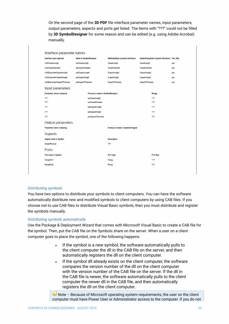
On the second page of the 3D PDF file interface parameter names, input parameters,
output parameters, aspects and ports get listed. The items with “???” could not be filled
by 3D SymbolDesigner for some reason and can be edited (e.g. using Adobe Acrobat)
manually.
Distributing symbols
You have two options to distribute your symbols to client computers. You can have the software
automatically distribute new and modified symbols to client computers by using CAB files. If you
choose not to use CAB files to distribute Visual Basic symbols, then you must distribute and register
the symbols manually.
Distributing symbols automatically
Use the Package & Deployment Wizard that comes with Microsoft Visual Basic to create a CAB file for
the symbol. Then, put the CAB file on the Symbols share on the server. When a user on a client
computer goes to place the symbol, one of the following happens:
• If the symbol is a new symbol, the software automatically pulls to the client computer the dll in the CAB file on the server, and then automatically registers the dll on the client computer.
• If the symbol dll already exists on the client computer, the software compares the version number of the dll on the client computer with the version number of the CAB file on the server. If the dll in the CAB file is newer, the software automatically pulls to the client computer the newer dll in the CAB file, and then automatically registers the dll on the client computer.
Note – Because of Microsoft operating system requirements, the user on the client computer must have Power User or Administrator access to the computer. If you do not

CAXPERTS 3D SYMBOLDESIGNER - AUGUST 2019 35
allow users to have Power User or Administrator access to the client computer, then you must distribute symbols manually. For more information, see Distributing Symbols Manually.
1. On the computer where you have created the symbols, start the Package & Deployment Wizard that comes with Microsoft Visual Basic.
2. Select the VB project for the symbol using Browse.
3. Click Package.
4. For the Package Type, select Internet Package, and then click Next >.
5. For the Package Folder, specify the folder that you have shared (C:\Symbols), and then click Next >.
6. On the Included Files page, clear all the checkboxes to the left of the file names to remove them from the package except for the dll of your symbol. That is, the only file name that should have a check next to it is the name of your symbol dll. Then click Next >.
7. On the File Source page, verify that your symbol dll file is the only file listed, and then click Next >.
8. On the Safety Settings page, keep the default settings, and then click Next >.
9. Click Finish.
10. Put the CAB file on the server symbols share.
11. Open the Excel workbook that contains the symbol part and go to the part sheet.
12. Create a new column on the sheet called Codebase.
13. In the Codebase column, type %CAB_SERVER%\name.CAB where name is the name of the symbol CAB file.
14. Type an M in the first cell of the row and re-bulkload the workbook.
Distributing symbols manually
If the symbol being distributed is an existing symbol that has been modified, the major version
number in the Visual Basic project properties must be increased by 1. Increasing the major version
number by 1 forces the recomputation of existing symbol occurrences when the Synchronize Model
With Catalog command in Project Management is run. If an existing symbol is modified and
distributed, all the new symbol occurrences will use the new symbol (unless the new occurrence uses
an existing entry of symbol's cache). If an existing symbol is modified and distributed, and an existing
occurrence is recomputed, it will use the new symbol if the recomputation results in creation of a new
entry in the symbol's cache.
1. Place the dll for the new or modified symbol on the server's symbols share.
2. On a client machine, copy the dll from the server to the local [Product Directory]\CatalogData\Symbols\bin folder.
3. Register the new .dll by clicking Start > Run and typing: regsvr32 "[Product Directory]\CatalogData\Symbols\bin\<name of dll>".
Repeat steps 2 and 3 on each client machine.
Recent documents
The most recently used files are listed here.

CAXPERTS 3D SYMBOLDESIGNER - AUGUST 2019 36
About CAXperts 3D SymbolDesigner
About shows a dialogue with information about the software product and version, the System Info
button starts Microsoft System Information which provides useful additional information about the
hardware and software configuration of the computer system.
Exit
Exit ends CAXperts 3D SymbolDesigner.
Project
Variants
A variant is a named group of parameter values which can be used for testing the parameterisation of
a symbol. Variants are exported to SmartPlant 3D bulk load sheets.
Insert variant
Insert variant ( ) inserts a variant in the symbol project.
Delete variant
Delete variant ( ) deletes the selected variant from the symbol project.
Parameters & custom interfaces
Add parameter
A parameter ( ) is an element of the symbol tree which consists of a name and a value. The name is
unique in the whole symbol project and can be referenced by any formula. A parameter is mapped to
a SmartPlant 3D parameter name by the SmartPlant 3D mapping row in the variants grid of the
symbol project. If a lookup in Config.xls in the data subdirectory of 3D SymbolDesigner shows that
this parameter name is there, the parameter mapping will get a green background; else it will stay red
which means that this parameter will not be exported to SmartPlant 3D. The user can also change the
mapping using the context menu (right click).

CAXPERTS 3D SYMBOLDESIGNER - AUGUST 2019 37
Add text parameter
A text parameter ( ) is an element of the symbol tree which consists of a name and a text value. The
name is unique in the whole symbol project and can be referenced by any formula. A text parameter is
mapped to a SmartPlant 3D parameter name by the SmartPlant 3D mapping row in the variants grid of
the symbol project. Text parameters may contain non-numeric values.
Add codelist parameter
A codelist parameter ( )
Define new attribute
Brings up a form to add single additional parameters to the config.xls.
Combine custom interfaces
Brings up a form where the user can select a folder with bulkload sheets and a target Excel file. The
function will evaluate all CustomInterfaces tabs and recombine them, the output goes to the selected
Excel file.
Bodies
3D SymbolDesigner contains the full set of shapes known from Intergraph PDS.
These are the rules as to how geometric transformations to a shape are applied:
1. The shape is placed at the origin of the world coordinate system (i.e. the locale coordinate system of the shape matches the world coordinate system (marked red-green-blue).
2. The shape’s geometry is scaled according to the values set in its .Geometry sub-tree.
3. The shape is rotated about the global X axis by the angle specified in its .Rotation.X item
4. The shape is rotated about the global Y axis by the angle specified in its .Rotation.Y item
5. The shape is rotated about the global Z axis by the angle specified in its .Rotation.Z item
6. The shape is translated by the distances specified in its .Translation subtree
Shapes already included with 3D SymbolDesigner are described below (the anchor of the shape is
marked magenta-yellow-cyan)
Cylinder
3D SymbolDesigner PDS Comment
L1
D1

CAXPERTS 3D SYMBOLDESIGNER - AUGUST 2019 38
Cylinder. Right Circular Cylinder (1)
.Translation.X X
.Translation.Y Y
.Translation.Z EL
.Geometry.L1 A
.Geometry.D1 B
Cone
3D SymbolDesigner PDS Comment
Cone. Right Circular Cone (2)
.Translation.X X
.Translation.Y Y
.Translation.Z EL
.Geometry.L1 A
.Geometry.D1 B
.Geometry.D2 C
Eccentric circular cone
3D SymbolDesigner PDS Comment
EccentricCircularCone. Eccentric Circular Cone (3)
L1
D1
D2
L1 D1
D2

CAXPERTS 3D SYMBOLDESIGNER - AUGUST 2019 39
.Translation.X X
.Translation.Y Y
.Translation.Z EL
.Geometry.A1 Angle of the left face
.Geometry.A2 Angle of the right face
.Geometry.AR1 Aspect ratio of the left face
.Geometry.AR2 Aspect ratio of the right face
.Geometry.L1 A
.Geometry.D1 B
.Geometry.D2 C
Truncated rectangular prism
3D SymbolDesigner PDS Comment
TruncatedRectangularPrism. Truncated Rectangular Prism (12)
.Translation.X X
.Translation.Y Y
.Translation.Z EL
.Geometry.L1 A
.Geometry.L2 B
.Geometry.L3 C
.Geometry.L4 D
.Geometry.L5 E
L3
L2
L1
L4 L5

CAXPERTS 3D SYMBOLDESIGNER - AUGUST 2019 40
Eccentric rectangular prism
3D SymbolDesigner PDS Comment
EccentricRectangularPrism. Eccentric Rectangular Prism (13)
.Translation.X X
.Translation.Y Y
.Translation.Z EL
.Geometry.A1 Angle of the left face
.Geometry.A2 Angle of the right face
.Geometry.L1 A
.Geometry.L2 B
.Geometry.L3 C
.Geometry.L4 D
.Geometry.L5 E
Octagonal solid
3D SymbolDesigner PDS Comment
OctagonalSolid. Octagonal Solid (8)
L3
L2
L1
L4
L5
L1
L4

CAXPERTS 3D SYMBOLDESIGNER - AUGUST 2019 41
.Translation.X X
.Translation.Y Y
.Translation.Z EL
.Geometry.L1 A
.Geometry.L2 B Ignored
.Geometry.L3 C
.Geometry.L4 D
Hexagonal solid
3D SymbolDesigner PDS Comment
HexagonalSolid. Hexagonal Solid (7)
.Translation.X X
.Translation.Y Y
.Translation.Z EL
.Geometry.L1 A
.Geometry.L2 B Ignored
.Geometry.L3 C
.Geometry.L4 D
L1
L4

CAXPERTS 3D SYMBOLDESIGNER - AUGUST 2019 42
Box
3D SymbolDesigner PDS Comment
Box. Rectangular Solid (6)
.Translation.X X
.Translation.Y Y
.Translation.Z EL
.Geometry.L1 A
.Geometry.L2 B
.Geometry.L3 C
Triangular solid
3D SymbolDesigner PDS Comment
TriangularSolid. Triangular Solid (5)
.Translation.X X
.Translation.Y Y
L1
L2
L3
L3
L2
L1
1:2

CAXPERTS 3D SYMBOLDESIGNER - AUGUST 2019 43
.Translation.Z EL
.Geometry.L1 A
.Geometry.L2 B
.Geometry.L3 C
.Geometry.A1 D Ignored
Extruded solid
Additional UV points can be added by Insert → Vertices → UV point
3D SymbolDesigner PDS Comment
ExtrudedSolid. User Projected Shape (9)
.Translation.X X
.Translation.Y Y
.Translation.Z EL
.Geometry.L1 Projection
.Geometry.Vertices.UVVector1.U 1 X
.Geometry.Vertices.UVVector1.V 1 Y
… …
.Geometry.Vertices.UVVector20.U 20 X
.Geometry.Vertices.UVVector20.V 20 Y
Sphere
p1(-1, 0)
p2(1, 0)
p3(0, 1)
L1
D1

CAXPERTS 3D SYMBOLDESIGNER - AUGUST 2019 44
3D SymbolDesigner PDS Comment
Sphere. Sphere (17)
.Translation.X X
.Translation.Y Y
.Translation.Z EL
.Geometry.D1 A
Semisphere
3D SymbolDesigner PDS Comment
Semisphere. Semi-Elliptical Head (4)
.Translation.X X
.Translation.Y Y
.Translation.Z EL
.Geometry.D1 A
.Geometry.R1 B
Rotational solid
See extruded solid. There is no similar object in PDS.
Transition element
D1
R1
D1
L2
L1
L3

CAXPERTS 3D SYMBOLDESIGNER - AUGUST 2019 45
3D SymbolDesigner PDS Comment
TransitionElement. Transition Element (15)
.Translation.X X
.Translation.Y Y
.Translation.Z EL
.Geometry.L1 A
.Geometry.L2 B
.Geometry.L3 C
.Geometry.D1 D
Eccentric transition element
3D SymbolDesigner PDS Comment
EccentricTransitionElement. Eccentric Transition Element (16)
.Translation.X X
.Translation.Y Y
.Translation.Z EL
.Geometry.A1 Angle of the left face
.Geometry.A2 Angle of the right face
.Geometry.L1 A
.Geometry.L2 B
.Geometry.L3 C
.Geometry.L4 1st offset of the right face
.Geometry.L5 2nd offset of the right face
.Geometry.D1 D
D1
L2
L1
L3

CAXPERTS 3D SYMBOLDESIGNER - AUGUST 2019 46
Torus
3D SymbolDesigner PDS Comment
Torus. Circular Torus (10)
.Translation.X X
.Translation.Y Y
.Translation.Z EL
.Geometry.D1 A
.Geometry.R1 B
.Geometry.A1 C
Rectangular torus
3D SymbolDesigner PDS Comment
D1
R1
A1
L1
R1
A1
L2

CAXPERTS 3D SYMBOLDESIGNER - AUGUST 2019 47
RectangularTorus. Rectangular Torus (11)
.Translation.X X
.Translation.Y Y
.Translation.Z EL
.Geometry.L1 A
.Geometry.L2 B
.Geometry.R1 C
.Geometry.A1 D
Vessel end
3D SymbolDesigner PDS Comment
.Geometry.D1 -
.Geometry.L1 -
.Geometry.EndType - E.g. DIN28013 or DIN28011
.Geometry.A1 -
Ports & connectors
A parameter collection ( , , , , , , )contains parameters which are usually provided by
SmartPlant 3D for the placement and dimensioning of nozzles. The user can set values in this
collection for testing purposes. The values are not exported, they will be provided at runtime by
SmartPlant 3D. Each connector needs a parameter collection of its own. Parameter collections get
mappings with grey background colour.
Cable connector
A Cable connector ( ) symbolises the start position and direction of cables leading away from the
symbol.
Cable tray connector
A Cable tray connector ( ) symbolises the start position, direction and orientation of cable trays
leading away from the symbol.
Conduit connector
A Conduit connector ( ) symbolises the start position and direction of conduits leading away from
the symbol.
Piping connector
A Piping connector ( , formerly Variable nozzle) symbolises the start position and direction of pipes
leading away from the symbol.
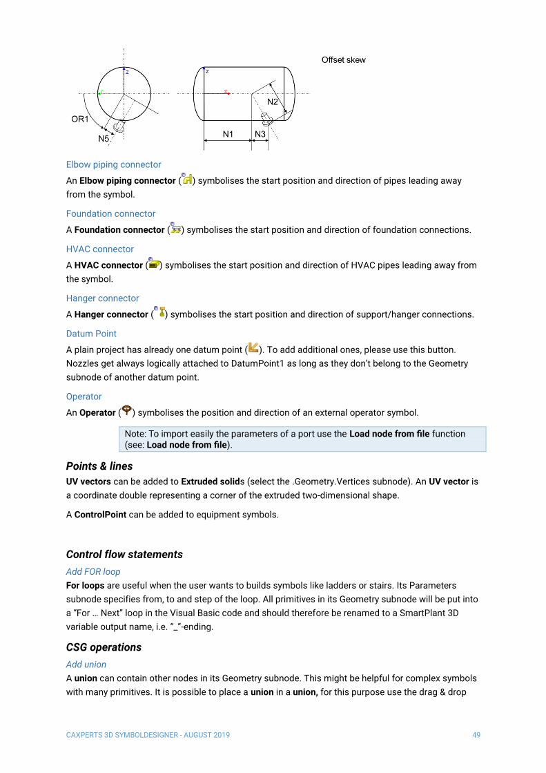
Smart piping connector for datum point based nozzles on equipment
Smart piping connectors ( ) use N1, N2, N3, N5 and OR1 to specify their position in relation to a
datum point. Therefore they can only be used within the Geometry subnode of a DatumPoint object
and will work on equipment symbols only. The following PlacementType values are allowed:

CAXPERTS 3D SYMBOLDESIGNER - AUGUST 2019 48
• Radial
• Tangential
• Axial
• Skew
• OffsetSkew
CAXPERTS 3D SYMBOLDESIGNER - AUGUST 2019 49
Elbow piping connector
An Elbow piping connector ( ) symbolises the start position and direction of pipes leading away
from the symbol.
Foundation connector
A Foundation connector ( ) symbolises the start position and direction of foundation connections.
HVAC connector
A HVAC connector ( ) symbolises the start position and direction of HVAC pipes leading away from
the symbol.
Hanger connector
A Hanger connector ( ) symbolises the start position and direction of support/hanger connections.
Datum Point
A plain project has already one datum point ( ). To add additional ones, please use this button.
Nozzles get always logically attached to DatumPoint1 as long as they don’t belong to the Geometry
subnode of another datum point.
Operator
An Operator ( ) symbolises the position and direction of an external operator symbol.
Note: To import easily the parameters of a port use the Load node from file function (see: Load node from file).
Points & lines
UV vectors can be added to Extruded solids (select the .Geometry.Vertices subnode). An UV vector is
a coordinate double representing a corner of the extruded two-dimensional shape.
A ControlPoint can be added to equipment symbols.
Control flow statements
Add FOR loop
For loops are useful when the user wants to builds symbols like ladders or stairs. Its Parameters
subnode specifies from, to and step of the loop. All primitives in its Geometry subnode will be put into
a “For … Next” loop in the Visual Basic code and should therefore be renamed to a SmartPlant 3D
variable output name, i.e. “_”-ending.
CSG operations
Add union
A union can contain other nodes in its Geometry subnode. This might be helpful for complex symbols
with many primitives. It is possible to place a union in a union, for this purpose use the drag & drop

CAXPERTS 3D SYMBOLDESIGNER - AUGUST 2019 50
function after creating the union. Also to put geometry bodies in the union use the drag & drop
function on the Union.Geometry node.
Parts
Configuration index calculator ( ) opens a “clone” of the Intergraph Configuration Index Calculator.
Edit
Object
The Object menu item is used to rotate and translate an object that means to turn it around the axes
X, Y or Z or to move it without rotating in X, Y or Z direction.
Clipboard
Cut
Cut ( ) cuts the selected item to the clipboard.
Copy
Copy ( ) copies the selected item to the clipboard.
Paste
Paste ( ) pastes the clipboard content to the selected item
Properties
Show properties
Show properties shows the properties dialogue.
Tree context menu
Save node to file
Save node to file ( ) allows the user to save the geometry data of a tree node (e.g.: cylinder, sphere,
union, etc.) to an xml file.
Load node to file
Load node to file ( ) allows the user to load the geometry data from an xml file to the tree.
Copy formula
Copy formula ( ) allows the user to copy the selected parameter formula to the clipboard. Used on a
rotation or translation node instead of a parameter, the x-, y-, and z- value will be copied.
Paste formula
Paste formula ( ) allows the user to paste the clipboard content to the selected parameter formula.
When used on a rotation or translation node the x-, y-, and z- value will be pasted.
View
The View menu is for configuring the visual appearance of the 3D SymbolDesigner Graphical User
Interface (GUI) and of the open symbol project.
Camera
Zoom in
If Zoom in ( ) is clicked, the distance between the camera and the object becomes shrunk (usually
by factor 0.5).
CAXPERTS 3D SYMBOLDESIGNER - AUGUST 2019 51
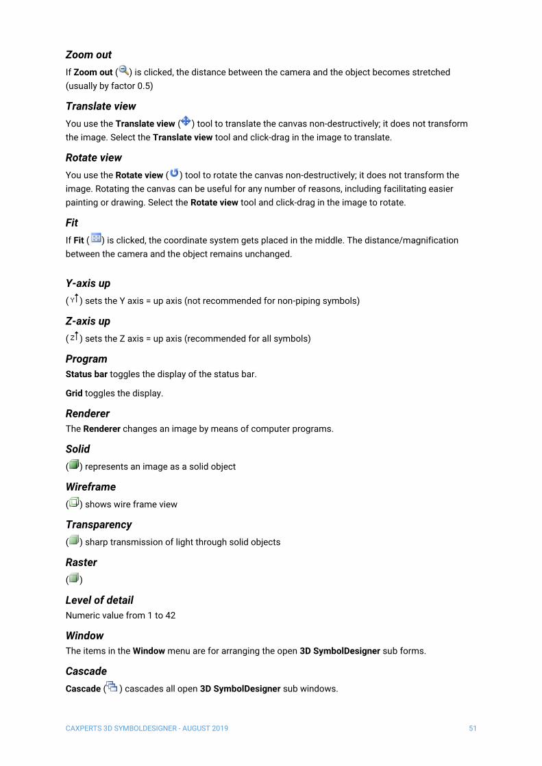
Zoom out
If Zoom out ( ) is clicked, the distance between the camera and the object becomes stretched
(usually by factor 0.5)
Translate view
You use the Translate view ( ) tool to translate the canvas non-destructively; it does not transform
the image. Select the Translate view tool and click-drag in the image to translate.
Rotate view
You use the Rotate view ( ) tool to rotate the canvas non-destructively; it does not transform the
image. Rotating the canvas can be useful for any number of reasons, including facilitating easier
painting or drawing. Select the Rotate view tool and click-drag in the image to rotate.
Fit
If Fit ( ) is clicked, the coordinate system gets placed in the middle. The distance/magnification
between the camera and the object remains unchanged.
Y-axis up
( ) sets the Y axis = up axis (not recommended for non-piping symbols)
Z-axis up
( ) sets the Z axis = up axis (recommended for all symbols)
Program
Status bar toggles the display of the status bar.
Grid toggles the display.
Renderer
The Renderer changes an image by means of computer programs.
Solid
( ) represents an image as a solid object
Wireframe
( ) shows wire frame view
Transparency
( ) sharp transmission of light through solid objects
Raster
( )
Level of detail
Numeric value from 1 to 42
Window
The items in the Window menu are for arranging the open 3D SymbolDesigner sub forms.
Cascade
Cascade ( ) cascades all open 3D SymbolDesigner sub windows.

CAXPERTS 3D SYMBOLDESIGNER - AUGUST 2019 52
Tile Horizontal
Tile Horizontal ( ) rearranges all open 3D SymbolDesigner sub windows in rows.
Tile Vertical
Tile Vertical ( ) rearranges all open 3D SymbolDesigner sub windows in columns.
Options
Configuration file
Open ( ) the selected configuration file.
Reload ( ) the selected configuration file (e.g. after changes in the configuration file)
Note: Don’t forget to save the configuration file before Reload.
Level
A debugging level is the importance of a process step that has to be reached to generate a log file
entry. These debugging levels are available:
• 0: Logs only critical errors
• 1: Logs all errors
• 2: Logs all errors and warnings
• 3: Logs all errors, warnings and major file operations
• 4: Logs all errors, warnings and minor file operations
• 5: Logs all errors, warnings and output operations
• 6: Logs almost everything (not recommended as it can slow down your system)
Log file folder
The log file folder is the folder where the 3D SymbolDesigner.log goes to. Use Browse… to select a
folder.
Database
The Database tab shows a dialogue for configuring the database connection.
Licence
See 0 Setup.
Help
shows the 3D SymbolDesigner online help.
Appendix
Angles
Angles are interpreted in radians if they are not followed by a degree sign (°). You can type PI or 180°
for an angle of 180°.
CAXPERTS 3D SYMBOLDESIGNER - AUGUST 2019 53
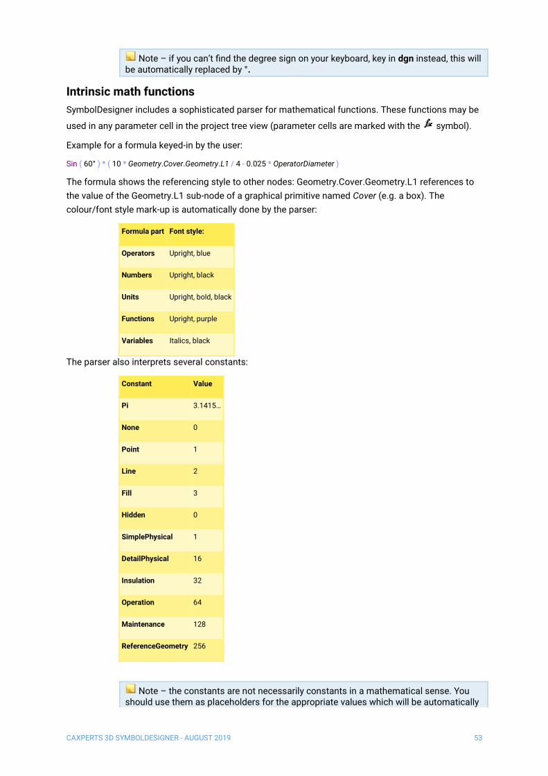
Note – if you can’t find the degree sign on your keyboard, key in dgn instead, this will be automatically replaced by °.
Intrinsic math functions
SymbolDesigner includes a sophisticated parser for mathematical functions. These functions may be
used in any parameter cell in the project tree view (parameter cells are marked with the symbol).
Example for a formula keyed-in by the user:
Sin ( 60° ) * ( 10 * Geometry.Cover.Geometry.L1 / 4 - 0.025 * OperatorDiameter )
The formula shows the referencing style to other nodes: Geometry.Cover.Geometry.L1 references to
the value of the Geometry.L1 sub-node of a graphical primitive named Cover (e.g. a box). The
colour/font style mark-up is automatically done by the parser:
Formula part Font style:
Operators Upright, blue
Numbers Upright, black
Units Upright, bold, black
Functions Upright, purple
Variables Italics, black
The parser also interprets several constants:
Constant Value
Pi 3.1415…
None 0
Point 1
Line 2
Fill 3
Hidden 0
SimplePhysical 1
DetailPhysical 16
Insulation 32
Operation 64
Maintenance 128
ReferenceGeometry 256
Note – the constants are not necessarily constants in a mathematical sense. You should use them as placeholders for the appropriate values which will be automatically

CAXPERTS 3D SYMBOLDESIGNER - AUGUST 2019 54
filled in by 3D SymbolDesigner: If in software A None means 0 but in software B None means -1, 3D SymbolDesigner will properly replace None according to the export target.
These are the pre-defined operators:
Operator Operation
+ Addition
- Subtraction
* Multiplication
/ Division
^ Power
( Left bracket
) Right bracket
These functions are supported by the parser:
Function Function name Description
Abs(x) Absolute value Returns the absolute value of x
Cos(x) Cosine trigonometric
function
Exp(x) Exponential function
Fix(x) Returns the integer portion of the operand. If x is negative, Fix returns the first
negative integer greater than or equal to x
Int(x) Returns the integer portion of the operand. If x is negative, Int returns the first
negative integer less than or equal to x
Ln(x) Natural logarithm
Max(x,y) Compares x and y and returns the greater operand
Min(x,y) Compares x and y and returns the smaller operand
Now(x) Returns the date (in Visual Basic)
Rnd(x) Returns a random number.
x <0 The same number every time, using x as the seed.
x=0 The most recently generated number.
x>0 The next random number in the sequence.
Sgn(x) Sign function Returns the sign of x
Sin(x) Sine trigonometric
function
Returns the sine of x (in radians)
Sqrt(x) Square root Returns the square root of x

CAXPERTS 3D SYMBOLDESIGNER - AUGUST 2019 55
Tan(x) Tangent trigonometric
function
Returns the tangent of x
Time Returns the seconds since midnight (in 3D SymbolDesigner)
Returns the time (in Visual Basic)
Asin(x) Inverse sine trigonometric
function
Asin(x) = Atan(x / Sqrt (-x * x + 1))
Acos(x) Inverse cosine
trigonometric function
Acos(x) = Atan(-x / Sqrt (-x * x + 1)) + 2 * Atan(1)
Atan(x) Inverse tangent
trigonometric function
Units are defined in the Config.xls in the data subdirectory of 3D SymbolDesigner.
Derived math functions
The following non-intrinsic math functions can be derived from the intrinsic math functions. These
functions are not yet included in 3D SymbolDesigner but will be included in a future version of the
software, so please regard the names of these functions as reserved:
Function Function name Derived equivalents
Sec(x) Secant Sec(x) = 1 / Cos(x)
CoSec(x) Cosecant CoSec(x) = 1 / Sin(x)
CoTan(x) Cotangent CoTan(x) = 1 / Tan(x)
ArcSec(x) Inverse Secant ArcSec(x) = ArcTan(x / Sqrt(x * x - 1)) + Sgn((x) -1) * (2 * ArcTan(1))
ArcCoSec(x) Inverse Cosecant ArcCoSec(x) = ArcTan(x / Sqrt(x * x - 1)) + (Sgn(x) - 1) * (2 * ArcTan(1))
ArcCoTan(x) Inverse Cotangent ArcCoTan(x) = ArcTan(x) + 2 * ArcTan(1)
HSin(x) Hyperbolic Sine HSin(x) = (Exp(x) - Exp(-x)) / 2
HCos(x) Hyperbolic Cosine HCos(x) = (Exp(x) + Exp(-x)) / 2
HTan(x) Hyperbolic Tangent HTan(x) = (Exp(x) - Exp(-x)) / (Exp(x) + Exp(-x))
HSec(x) Hyperbolic Secant HSec(x) = 2 / (Exp(x) + Exp(-x))
HCoSec(x) Hyperbolic Cosecant HCoSec(x) = 2 / (Exp(x) - Exp(-x))
HCoTan(x) Hyperbolic Cotangent HCoTan(x) = (Exp(x) + Exp(-x)) / (Exp(x) - Exp(-x))
HArcSin(x) Inverse Hyperbolic Sine HArcSin(x) = Log(x + Sqrt(x * x + 1))
HArcCos(x) Inverse Hyperbolic Cosine HArcCos(x) = Log(x + Sqrt(x * x - 1))
HArcTan(x) Inverse Hyperbolic Tangent HArcTan(x) = Log((1 + x) / (1 - x)) / 2
HArcSec(x) Inverse Hyperbolic Secant HArcSec(x) = Log((Sqrt(-x * x + 1) + 1) / x)
CAXPERTS 3D SYMBOLDESIGNER - AUGUST 2019 56
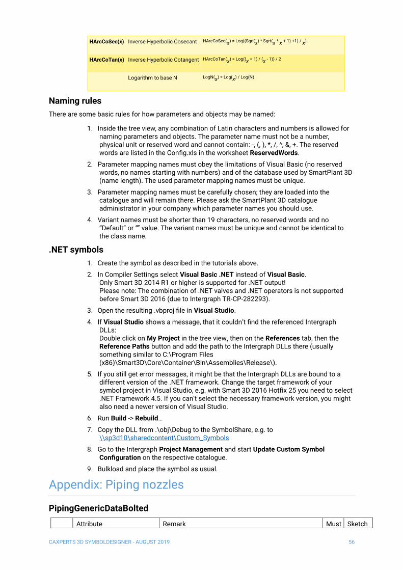
HArcCoSec(x) Inverse Hyperbolic Cosecant HArcCoSec(x) = Log((Sgn(x) * Sqrt(x * x + 1) +1) / x)
HArcCoTan(x) Inverse Hyperbolic Cotangent HArcCoTan(x) = Log((x + 1) / (x - 1)) / 2
Logarithm to base N LogN(x) = Log(x) / Log(N)
Naming rules
There are some basic rules for how parameters and objects may be named:
1. Inside the tree view, any combination of Latin characters and numbers is allowed for naming parameters and objects. The parameter name must not be a number, physical unit or reserved word and cannot contain: -, (, ), *, /, ^, &, +. The reserved words are listed in the Config.xls in the worksheet ReservedWords.
2. Parameter mapping names must obey the limitations of Visual Basic (no reserved words, no names starting with numbers) and of the database used by SmartPlant 3D (name length). The used parameter mapping names must be unique.
3. Parameter mapping names must be carefully chosen; they are loaded into the catalogue and will remain there. Please ask the SmartPlant 3D catalogue administrator in your company which parameter names you should use.
4. Variant names must be shorter than 19 characters, no reserved words and no “Default” or “” value. The variant names must be unique and cannot be identical to the class name.
.NET symbols
1. Create the symbol as described in the tutorials above.
2. In Compiler Settings select Visual Basic .NET instead of Visual Basic. Only Smart 3D 2014 R1 or higher is supported for .NET output! Please note: The combination of .NET valves and .NET operators is not supported before Smart 3D 2016 (due to Intergraph TR-CP-282293).
3. Open the resulting .vbproj file in Visual Studio.
4. If Visual Studio shows a message, that it couldn’t find the referenced Intergraph DLLs: Double click on My Project in the tree view, then on the References tab, then the Reference Paths button and add the path to the Intergraph DLLs there (usually something similar to C:\Program Files (x86)\Smart3D\Core\Container\Bin\Assemblies\Release\).
5. If you still get error messages, it might be that the Intergraph DLLs are bound to a different version of the .NET framework. Change the target framework of your symbol project in Visual Studio, e.g. with Smart 3D 2016 Hotfix 25 you need to select .NET Framework 4.5. If you can’t select the necessary framework version, you might also need a newer version of Visual Studio.
6. Run Build -> Rebuild…
7. Copy the DLL from .\obj\Debug to the SymbolShare, e.g. to \\sp3d10\sharedcontent\Custom_Symbols
8. Go to the Intergraph Project Management and start Update Custom Symbol Configuration on the respective catalogue.
9. Bulkload and place the symbol as usual.
Appendix: Piping nozzles
PipingGenericDataBolted
Attribute Remark Must Sketch

CAXPERTS 3D SYMBOLDESIGNER - AUGUST 2019 57
1 NominalPipingDiameter Input X
2 NominalDiameterUnits Input X
3 PressureRating Input, Codelist X
(3a) (RatingPractice) Input, Codelist PressureRating, Parent of PressureRating X
4 EndPreparation Input, Codelist X
(4a) (TerminationSubClass) Input, Codelist EndPreparation, Parent of EndPreparation X
(4b) (TerminationClass) Input, Codelist EndPreparation, Parent of TerminationSubClass X
5 EndStandard Input, Codelist X
(5a) (EndPractice) Input, Codelist EndStandard, Parent of EndStandard X
6 FlangeOutsideDiameter see sketch X A
7 FlangeThickness see sketch (X) B
8 FlangeThicknessTolerance is required for computing bolt length
9 FlangeFaceProjection see sketch C
10 RaisedFaceDiameter see sketch D
11 FlangeGrooveWidth see sketch E
12 SeatingDepth see sketch F
13 BoltCircleDiameter see sketch (X) G
14 QuantityOfBoltsRequired (X)
15 BoltDiameter (X)
16 BodyOutsideDiameter see sketch (X) H
17 DrillingTemplatePattern Codelist
18 BoltPatternLength used for not circular bolted ports
19 BoltPatternWidth used for not circular bolted ports
20 GroovePitchDiameter used for ring type joint flanged ends only
21 LapThickness used for lap joint flange without stub end (part) only
22 CounterBoreDepth used for Bolt Type="Cap screw, socket head, counter bore" only
23 BoltPatternOffset used for not circular bolted ports

CAXPERTS 3D SYMBOLDESIGNER - AUGUST 2019 58
PipingGenericDataFemale
Attribute Remark Must Sketch
1 NominalPipingDiameter Input X
2 NominalDiameterUnits Input X
3 PressureRating Input, Codelist
(3a) (RatingPractice) Input, Codelist PressureRating, Parent of PressureRating
4 Schedule Input, Codelist ScheduleThickness
(4a) (ScheduleThicknessPractice) Input, Codelist ScheduleThickness, Parent of Schedule
5 EndPreparation Input, Codelist X
(5a) (TerminationSubClass) Input, Codelist EndPreparation, Parent of EndPreparation X
(5b) (TerminationClass) Input, Codelist EndPreparation, Parent of TerminationSubClass X
6 EndStandard Input, Codelist X
(6a) (EndPractice) Input, Codelist EndStandard, Parent of EndStandard X
7 SocketDiameter see sketch X A
8 SocketDepth see sketch B
9 SocketOffset see sketch C
10 ThreadDepth see sketch D
11 HubOutsideDiameter see sketch (X) E
12 HubThickness see sketch (X) F
13 SocketWallThickness see sketch G
14 BodyOutsideDiameter see sketch (X) H

CAXPERTS 3D SYMBOLDESIGNER - AUGUST 2019 59
PlainPipingGenericData
Attribute Remark Must Sketch
1 NominalPipingDiameter Input X
2 NominalDiameterUnits Input X
3 PressureRating Input, Codelist
(3a) (RatingPractice) Input, Codelist PressureRating, Parent of PressureRating
4 Schedule Input, Codelist ScheduleThickness
(4a) (ScheduleThicknessPractice) Input, Codelist ScheduleThickness, Parent of Schedule
5 EndStandard Input, Codelist X
(5a) (EndPractice) Input, Codelist EndStandard, Parent of EndStandard X
6 PipingOutsideDiameter see sketch (X) A
7 WallThickness see sketch B
CAXPERTS 3D SYMBOLDESIGNER - AUGUST 2019 60
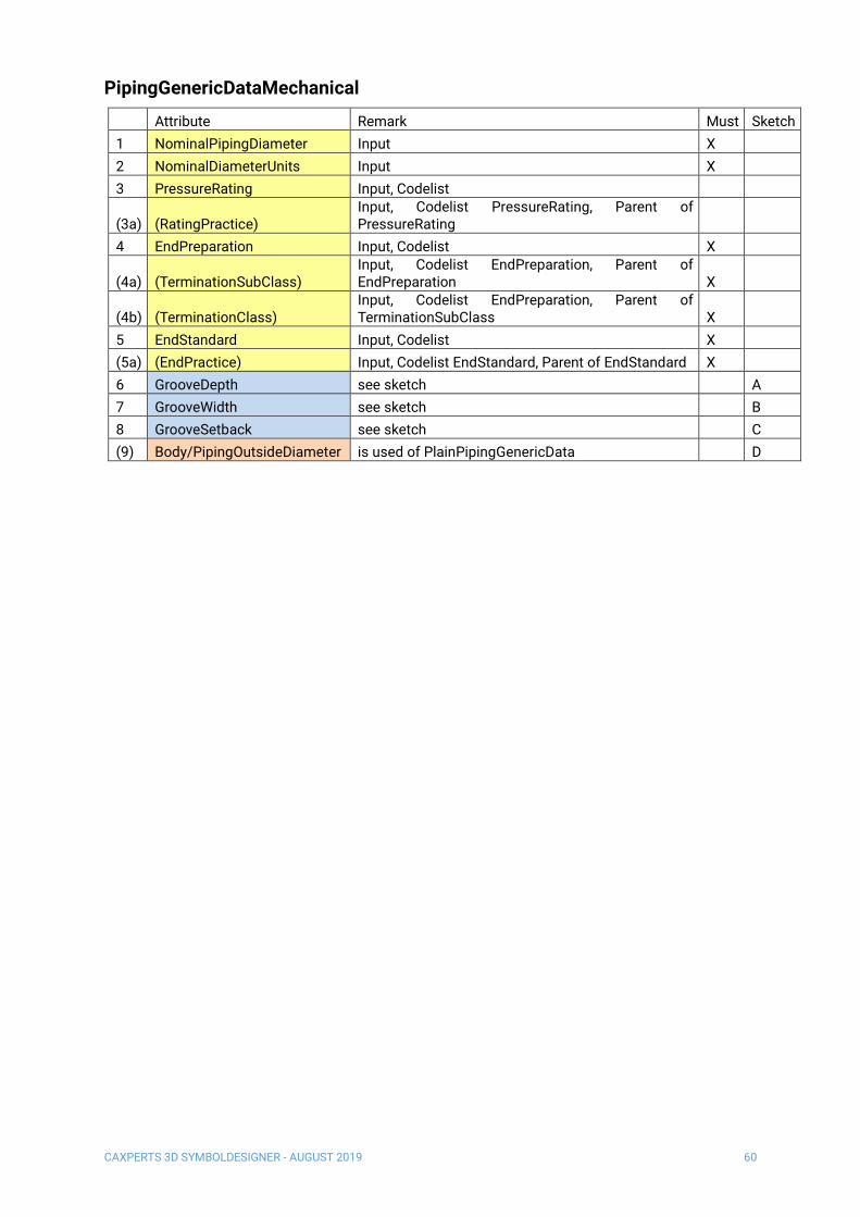
PipingGenericDataMechanical
Attribute Remark Must Sketch
1 NominalPipingDiameter Input X
2 NominalDiameterUnits Input X
3 PressureRating Input, Codelist
(3a) (RatingPractice) Input, Codelist PressureRating, Parent of PressureRating
4 EndPreparation Input, Codelist X
(4a) (TerminationSubClass) Input, Codelist EndPreparation, Parent of EndPreparation X
(4b) (TerminationClass) Input, Codelist EndPreparation, Parent of TerminationSubClass X
5 EndStandard Input, Codelist X
(5a) (EndPractice) Input, Codelist EndStandard, Parent of EndStandard X
6 GrooveDepth see sketch A
7 GrooveWidth see sketch B
8 GrooveSetback see sketch C
(9) Body/PipingOutsideDiameter is used of PlainPipingGenericData D
CAXPERTS 3D SYMBOLDESIGNER - AUGUST 2019 61
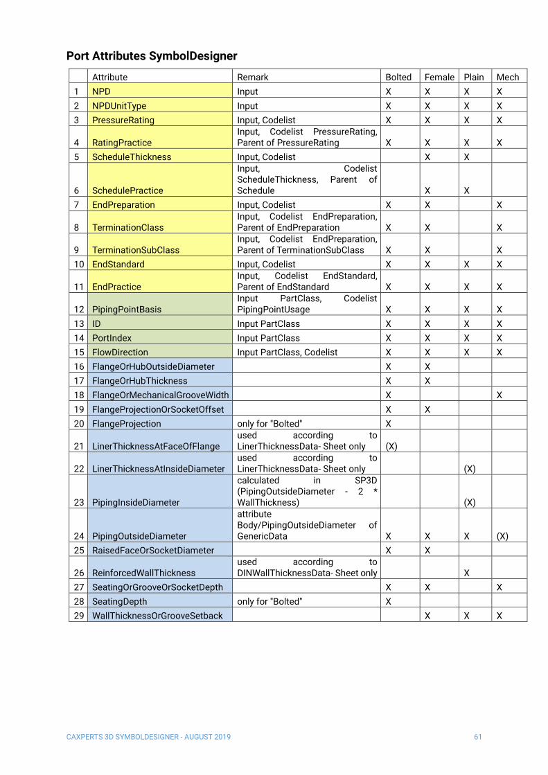
Port Attributes SymbolDesigner
Attribute Remark Bolted Female Plain Mech
1 NPD Input X X X X
2 NPDUnitType Input X X X X
3 PressureRating Input, Codelist X X X X
4 RatingPractice Input, Codelist PressureRating, Parent of PressureRating X X X X
5 ScheduleThickness Input, Codelist X X
6 SchedulePractice
Input, Codelist ScheduleThickness, Parent of Schedule X X
7 EndPreparation Input, Codelist X X X
8 TerminationClass Input, Codelist EndPreparation, Parent of EndPreparation X X X
9 TerminationSubClass Input, Codelist EndPreparation, Parent of TerminationSubClass X X X
10 EndStandard Input, Codelist X X X X
11 EndPractice Input, Codelist EndStandard, Parent of EndStandard X X X X
12 PipingPointBasis Input PartClass, Codelist PipingPointUsage X X X X
13 ID Input PartClass X X X X
14 PortIndex Input PartClass X X X X
15 FlowDirection Input PartClass, Codelist X X X X
16 FlangeOrHubOutsideDiameter X X
17 FlangeOrHubThickness X X
18 FlangeOrMechanicalGrooveWidth X X
19 FlangeProjectionOrSocketOffset X X
20 FlangeProjection only for "Bolted" X
21 LinerThicknessAtFaceOfFlange used according to LinerThicknessData- Sheet only (X)
22 LinerThicknessAtInsideDiameter used according to LinerThicknessData- Sheet only (X)
23 PipingInsideDiameter
calculated in SP3D (PipingOutsideDiameter - 2 * WallThickness) (X)
24 PipingOutsideDiameter
attribute Body/PipingOutsideDiameter of GenericData X X X (X)
25 RaisedFaceOrSocketDiameter X X
26 ReinforcedWallThickness used according to DINWallThicknessData- Sheet only X
27 SeatingOrGrooveOrSocketDepth X X X
28 SeatingDepth only for "Bolted" X
29 WallThicknessOrGrooveSetback X X X

CAXPERTS 3D SYMBOLDESIGNER - AUGUST 2019 62

CAXPERTS 3D SYMBOLDESIGNER - AUGUST 2019 63
Contact
Contact CAXperts’ support by email, online, or phone:
CAXperts GmbH
Carl-Zeiss-Ring 4
85737 Ismaning
Germany
https://www.caxperts.com/contact/
Phone: +49 (89) 969772-0
Email: [email protected]
Helpdesk
Available Monday to Friday 08.00 a.m. – 5.00 pm (UTC +1)
Phone: +49 (89) 969772-250