cb 2 series - code blue corporation--emergency blue light ... · code blue • 259 hedcor street...
TRANSCRIPT

800.205.7186 • www.codeblue.com
Administrator Guide
CB 2 Series
Installation | Confi guration | Operation | Troubleshooting

Code Blue • 259 Hedcor Street • Holland, MI 49423 USA • 800.205.7186 • www.codeblue.com GU-149-AApage 2 of 63
CB 2 SeriesAdministrator Guide
WARNINGONLY QUALIFIED PERSONNEL SHOULD INSTALL THESE UNITS. THE INSTALLATION SHOULD CONFORM TO ALL LOCAL CODES. IN SOME COUNTRIES, A CERTIFIED ELECTRI-CIAN MAY BE REQUIRED.
NOTICE TO USERS
Copyright © Code Blue Corporation. All rights reserved. This guide or software described herein, in whole or part, shall not be reproduced, translated or reduced to any machine-readable form without prior written approval from Code Blue Corporation.
CODE BLUE CORPORATION PROVIDES NO WARRANTY WITH REGARD TO THIS GUIDE, THE SOFTWARE OR OTHER INFORMATION CONTAINED HEREIN AND HEREBY EXPRESSLY DIS-CLAIMS ANY IMPLIED WARRANTIES OF MERCHANTABILITY OR FITNESS FOR ANY PARTICU-LAR PURPOSE WITH REGARD TO THIS GUIDE, THE SOFTWARE OR SUCH OTHER INFORMA-TION. IN NO EVENT SHALL CODE BLUE CORPORATION BE LIABLE FOR ANY INCIDENTAL, CONSEQUENTIAL, OR SPECIAL DAMAGES, WHETHER BASED ON TORT, CONTRACT, OR OTHERWISE, ARISING OUT OF OR IN CONNECTIONS WITH THIS GUIDE, THE SOFTWARE OR OTHER INFORMATION CONTAINED HEREIN OR THE USE THEREOF.
Code Blue Corporation reserves the right to make any modifications to this guide or the information contained herein at any time without notice. The software described herein may also be governed by the terms of a separate user license agreement.
Code Blue® is a registered trademark of Code Blue Corporation.

Code Blue • 259 Hedcor Street • Holland, MI 49423 USA • 800.205.7186 • www.codeblue.com GU-149-AApage 3 of 63
CB 2 SeriesAdministrator Guide
Table of Contents(NOTE: Phone programming instructions can be found in the IP5000 and IA4100 Guides.)
Section Page 2 Introduction.................................................................................... 5 3 Getting Started............................................................................... 6 4 Spare Parts..................................................................................... 7 5 Power Requirements...................................................................... 9 6 Legacy Power Requirements.........................................................12 7 Software Configuration..................................................................14 8 CB 2-a Exploded View....................................................................15 9 CB 2-e Exploded View....................................................................1610 Legacy CB 2-e Low Voltage Exploded View.................................1711 Legacy CB 2-e High Voltage Exploded View................................1812 CB 2-s Low Voltage Exploded View...............................................1913 CB 2-s High Voltage Exploded View..............................................2014 How to Replace LED Light Connectors........................................2115 CB 2-a Installation Instructions.....................................................2316 CB 2-e Installation Instructions.....................................................2617 Legacy CB 2-e Installation Instructions........................................2918 Legacy CB 2-e with Public Address Installation Instructions....3219 Legacy CB 2-e with AED Housing Installation Instructions.......3520 CB 2-s Installation Instructions.....................................................3821 Pole Mount Bracket Installation Instructions...............................4122 AED Access and Maintenance Guide............................................4223 CB 2 Series Remote Mount Beacon/Strobe Installation..............4324 S-1000/S-1050/S-2000 Installation Instructions............................4425 CB 2-a Standard Wiring Diagram...................................................4626 CB 2-a PoE Diagram.......................................................................4727 Legacy CB 2-a Standard Wiring Diagram (prior to 2020)....................4828 CB 2-e Standard Wiring Diagram..................................................4929 CB 2-e PoE Diagram.......................................................................5030 CB 2-e Standard Wiring Diagram (2015-2020) (with Triad Transformer)........5131 Legacy PoE Installation Instructions (prior to 2020)...........................52

Code Blue • 259 Hedcor Street • Holland, MI 49423 USA • 800.205.7186 • www.codeblue.com GU-149-AApage 4 of 63
CB 2 SeriesAdministrator Guide
32 CB 2 24V or Multi-Tap Power Brick Wiring (prior to 2020)..................53 33 CB 2 Series Standard Wiring (prior to 3/2013) (with Hammond Transformer)....5434 Legacy Cb 2-e with Public Address Wiring Diagram..................5535 Legacy CB 2-e with AED Housing Wiring Diagram.....................5636 CB 2-s Wiring Diagram...................................................................5737 Multi-Tap Transformer Wiring........................................................5838 Maintenance Schedule...................................................................5939 Locating Unit Serial Numbers.......................................................6140 Warranty...........................................................................................6241 Download Information....................................................................63

Code Blue • 259 Hedcor Street • Holland, MI 49423 USA • 800.205.7186 • www.codeblue.com GU-149-AApage 5 of 63
CB 2 SeriesAdministrator Guide
2 IntroductionThe 2 Series Wall Mount Help Points®
This popular line is a good fi t for any indoor or outdoor application, including parking facilities. Our unmistakable craftsmanship makes our Help Points® the most rugged on the market, withstanding the punishment of natural and man-made disasters. All 2 Series units have a rugged steel construc-tion, shatterproof Lexan Lens, industrial engineering grade refl ective graphics and weather, UV and graffi ti resistant paint, and are illuminated by a high-powered, 270 lumens/92 candela LED blue beacon/strobe. Other options include:
• IP and analog phones
• Long-life LED area light
• Low power consumption LED faceplate light
• Camera and card reader openings
• Temperature-controlled automated external defi brillator (AED) housing
• Public address speakers
CB 2-e CB 2-e with Public Address CB 2-e with AED HousingCB 2-e with AED HousingCB 2-e with AED Housing CB 2-sCB 2-a

Code Blue • 259 Hedcor Street • Holland, MI 49423 USA • 800.205.7186 • www.codeblue.com GU-149-AApage 6 of 63
CB 2 SeriesAdministrator Guide
3 Getting Started Basic Install Instructions
1. EIA/TIA, ANSI, CSA and BICSI cabling or similar standards shall be adhered to for proper operation of Code Blue communication devices connected to copper or fiber infrastructures. Communications cable and electrical cable in the same conduit is not an acceptable instal- lation and shall not be supported. Analog phones require a minimum of 23mA for proper operation (26-29mA recommended).
2. Each analog speakerphone requires its own phone line or PBX extension. Multiple units shall not be supported.
3. Speakerphones require programming before operation. Consult the User Guide or Administrator Guide enclosed with the unit or visit www.codeblue.com > Support > Downloads to read or download manuals.
4. If you are installing IP speakerphones, please read the appropriate manuals and consult with your Network Administrator.
5. Size electrical wiring based on length of run.
6. Consult the enclosed document packet for internal wiring instructions.
Tools Required
CB 2 Series
1. Drill and security bit for removing and inserting security screws on phone and access plate
2. Phillips head screwdriver and flat head screwdriver
3. 3/8 socket set to mount unit onto wall

Code Blue • 259 Hedcor Street • Holland, MI 49423 USA • 800.205.7186 • www.codeblue.com GU-149-AApage 7 of 63
CB 2 SeriesAdministrator Guide
4 Spare Parts
CB 2-a & CB 2-e (2020)Part Part Number
S-2000 LED Strobe Light 41162Analog Phone Line Surge Suppressor 41471IP Phone Line Surge Suppressor 41421DIN Rail Assy 40110PoE Switch 41574Button Head Screws 41500HID Lens 41164
Legacy CB 2-ePart Part Number
LED Strobe Light 40159Button Head Security Screws (3-pack) 41500Analog Phone Line Surge Suppressor 41471IP Phone Line Surge Suppressor 41421Manifold R/B 5-way 40101Power Brick 120V, 240V & 277V 40104
Legacy CB 2-e with Public Address Part Part Number
LED Strobe Light 40159Button Head Security Screws (3-pack) 41500Analog Phone Line Surge Suppressor 41471IP Phone Line Surge Suppressor 41421Manifold R/B 5-way 40101PAS AMP Kit 24V 40009Power Brick 120V, 240V & 277V 40104PAS Speaker 40080

Code Blue • 259 Hedcor Street • Holland, MI 49423 USA • 800.205.7186 • www.codeblue.com GU-149-AApage 8 of 63
CB 2 SeriesAdministrator Guide
Legacy CB 2-e with AED HousingPart Part Number
LED Strobe Light 40159Button Head Security Screws (3-pack) 41500Analog Phone Line Surge Suppressor 41471IP Phone Line Surge Suppressor 41421Manifold R/B 5-way 40101Power Brick 120V, 240V & 277V 40104AED Housing Door Release Mechanism 41104AED Housing Heater 41105AED Housing Thermostat 41106AED Housing Door Controller 41107AED Housing Retrofit kit 40012
CB 2-s Part Part Number
LED Strobe Light 40159Button Head Security Screws (3-pack) 41500Analog Phone Line Surge Suppressor 41471IP Phone Line Surge Suppressor 41421Manifold R/B 5-way 40101Power Brick 120V, 240V & 277V 40104LED Area Light 41539
CB 2 Series Additional OptionsQuantity Part Description
1 Document packet (Installation and Setup)1 Hardware packet4 Lag screw sleeves4 Metal washers4 Rubber washers1 Security bit1 Enclosure2 10/24 Counter sunk security screws – CB 2-s only2 Key fobs – CB 2-e with AED only
Code Blue • 259 Hedcor Street • Holland, MI 49423 USA • 800.205.7186 • www.codeblue.com GU-149-AApage 9 of 63
CB 2 SeriesAdministrator Guide
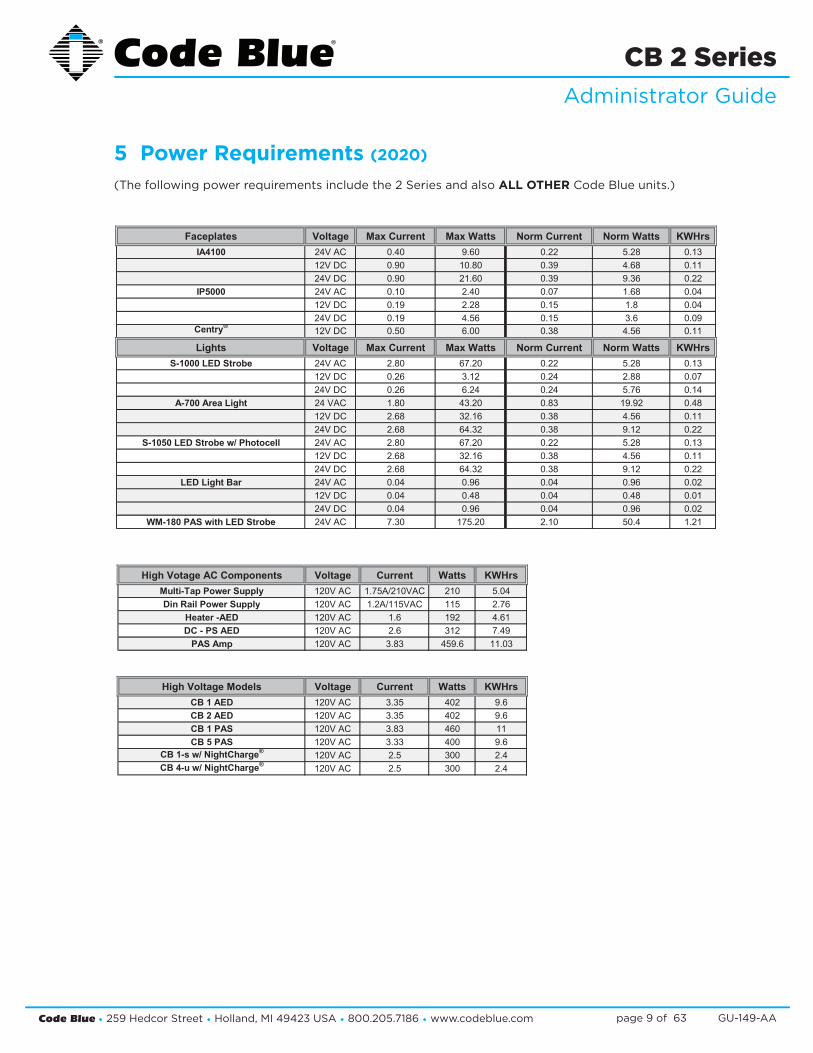
5 Power Requirements (2020) (The following power requirements include the 2 Series and also ALL OTHER Code Blue units.)
Component SpecsFaceplates Voltage Max Current Max Watts Norm Current Norm Watts KWHrs High Votage AC Components Voltage Current Watts KWHrs
IA4100 24V AC 0.40 9.60 0.22 5.28 0.13 Multi-Tap Power Supply 120V AC 1.75A/210VAC 210 5.0412V DC 0.90 10.80 0.39 4.68 0.11 Din Rail Power Supply 120V AC 1.2A/115VAC 115 2.7624V DC 0.90 21.60 0.39 9.36 0.22 Heater -AED 120V AC 1.6 192 4.61
IP5000 24V AC 0.10 2.40 0.07 1.68 0.04 DC - PS AED 120V AC 2.6 312 7.4912V DC 0.19 2.28 0.15 1.8 0.04 PAS Amp 120V AC 3.83 459.6 11.0324V DC 0.19 4.56 0.15 3.6 0.09
Centry®12V DC 0.50 6.00 0.38 4.56 0.11
Lights Voltage Max Current Max Watts Norm Current Norm Watts KWHrs High Voltage Models Voltage Current Watts KWHrsS-1000 LED Strobe 24V AC 2.80 67.20 0.22 5.28 0.13 CB 1 AED 120V AC 3.35 402 9.6
12V DC 0.26 3.12 0.24 2.88 0.07 CB 2 AED 120V AC 3.35 402 9.624V DC 0.26 6.24 0.24 5.76 0.14 CB 1 PAS 120V AC 3.83 460 11
A-700 Area Light 24 VAC 1.80 43.20 0.83 19.92 0.48 CB 5 PAS 120V AC 3.33 400 9.612V DC 2.68 32.16 0.38 4.56 0.11 CB 1-s w/ NightCharge® 120V AC 2.5 300 2.424V DC 2.68 64.32 0.38 9.12 0.22 CB 4-u w/ NightCharge® 120V AC 2.5 300 2.4
S-1050 LED Strobe w/ Photocell 24V AC 2.80 67.20 0.22 5.28 0.1312V DC 2.68 32.16 0.38 4.56 0.1124V DC 2.68 64.32 0.38 9.12 0.22
LED Light Bar 24V AC 0.04 0.96 0.04 0.96 0.0212V DC 0.04 0.48 0.04 0.48 0.0124V DC 0.04 0.96 0.04 0.96 0.02
WM-180 PAS with LED Strobe 24V AC 7.30 175.20 2.10 50.4 1.21
Common ConfigurationsModels With IA4100 Faceplate Voltage Current Watts KWHrs Models With IP5000 Faceplate Voltage Current Watts KWHrs
CB 1-e 24V AC 0.48 11.52 0.28 CB 1-e 24V AC 0.33 7.92 0.1912V DC 0.67 8.04 0.19 12V DC 0.43 5.16 0.1224V DC 0.67 16.08 0.39 24V DC 0.43 10.32 0.25
CB 1-s 24V AC 1.31 31.44 0.75 CB 1-s 24V AC 1.16 27.84 0.6712V DC 1.05 12.60 0.30 12V DC 0.81 9.72 0.2324V DC 1.05 25.20 0.60 24V DC 0.81 19.44 0.47
CB 5-s/5-p 24V AC 0.48 11.52 0.28 CB 5-s/5-p 24V AC 0.33 7.92 0.1912V DC 0.67 8.04 0.19 12V DC 0.43 5.16 0.1224V DC 0.67 16.08 0.39 24V DC 0.43 10.32 0.25
CB 9-s 24V AC 0.26 6.24 0.15 CB 9-s 24V AC 0.11 2.64 0.0612V DC 0.43 5.16 0.12 12V DC 0.19 2.28 0.0524V DC 0.43 10.32 0.25 24V DC 0.19 4.56 0.11
CB 2-e 24V AC 0.44 10.56 0.25 CB 2-e 24V AC 0.29 6.96 0.1712V DC 0.63 7.56 0.18 12V DC 0.39 4.68 0.1124V DC 0.63 15.12 0.36 24V DC 0.39 9.36 0.22
CB 2-a 24V AC 0.48 11.52 0.28 CB 2-a 24V AC 0.33 7.92 0.1912V DC 0.67 8.04 0.19 12V DC 0.43 5.16 0.1224V DC 0.67 16.08 0.39 24V DC 0.43 10.32 0.25
CB 2-s 24V AC 1.31 31.44 0.75 CB 2-s 24V AC 1.16 27.84 0.6712V DC 1.05 12.60 0.30 12V DC 0.81 9.72 0.2324V DC 1.05 25.20 0.60 24V DC 0.81 19.44 0.47
CB 2-e W/ PAS 24V AC 6.44 154.56 3.71 CB 2-e / PAS 24V AC 6.44 154.56 3.71CB 4-s 24V AC 0.22 5.28 0.13 CB 4-s 24V AC 0.07 1.68 0.04
12V DC 0.39 4.68 0.11 12V DC 0.15 1.8 0.0424V DC 0.39 9.36 0.22 24V DC 0.15 3.6 0.09
CB 4-r 24V AC 0.26 6.24 0.15 CB 4-r 24V AC 0.11 2.64 0.0612V DC 0.43 5.16 0.12 12V DC 0.19 2.28 0.0524V DC 0.43 10.32 0.25 24V DC 0.19 4.56 0.11
CB 4-u 24V AC 0.26 6.24 0.15 CB 4-u 24V AC 0.11 2.64 0.0612V DC 0.43 5.16 0.12 12V DC 0.19 2.28 0.0524V DC 0.43 10.32 0.25 24V DC 0.19 4.56 0.11
Surface Mount/Flush Mount 24V AC 0.22 5.28 0.13 Surface Mount/Flush Mount 24V AC 0.07 1.68 0.0412V DC 0.39 4.68 0.11 12V DC 0.15 1.8 0.0424V DC 0.39 9.36 0.22 24V DC 0.15 3.6 0.09
CB RT 24V AC 1.10 26.33 0.63 CB RT 24V AC 1.21 28.96 0.7012V DC 0.81 9.75 0.23 12V DC 1.03 12.37 0.3024V DC 1.61 38.57 0.93 24V DC 1.13 27.10 0.65
Code Blue • 259 Hedcor Street • Holland, MI 49423 USA • 800.205.7186 • www.codeblue.com GU-149-AApage 10 of 63
CB 2 SeriesAdministrator Guide
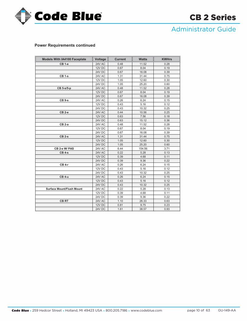
Power Requirements continued
Component SpecsFaceplates Voltage Max Current Max Watts Norm Current Norm Watts KWHrs High Votage AC Components Voltage Current Watts KWHrs
IA4100 24V AC 0.40 9.60 0.22 5.28 0.13 Multi-Tap Power Supply 120V AC 1.75A/210VAC 210 5.0412V DC 0.90 10.80 0.39 4.68 0.11 Din Rail Power Supply 120V AC 1.2A/115VAC 115 2.7624V DC 0.90 21.60 0.39 9.36 0.22 Heater -AED 120V AC 1.6 192 4.61
IP5000 24V AC 0.10 2.40 0.07 1.68 0.04 DC - PS AED 120V AC 2.6 312 7.4912V DC 0.19 2.28 0.15 1.8 0.04 PAS Amp 120V AC 3.83 459.6 11.0324V DC 0.19 4.56 0.15 3.6 0.09
Centry®12V DC 0.50 6.00 0.38 4.56 0.11
Lights Voltage Max Current Max Watts Norm Current Norm Watts KWHrs High Voltage Models Voltage Current Watts KWHrsS-1000 LED Strobe 24V AC 2.80 67.20 0.22 5.28 0.13 CB 1 AED 120V AC 3.35 402 9.6
12V DC 0.26 3.12 0.24 2.88 0.07 CB 2 AED 120V AC 3.35 402 9.624V DC 0.26 6.24 0.24 5.76 0.14 CB 1 PAS 120V AC 3.83 460 11
A-700 Area Light 24 VAC 1.80 43.20 0.83 19.92 0.48 CB 5 PAS 120V AC 3.33 400 9.612V DC 2.68 32.16 0.38 4.56 0.11 CB 1-s w/ NightCharge® 120V AC 2.5 300 2.424V DC 2.68 64.32 0.38 9.12 0.22 CB 4-u w/ NightCharge® 120V AC 2.5 300 2.4
S-1050 LED Strobe w/ Photocell 24V AC 2.80 67.20 0.22 5.28 0.1312V DC 2.68 32.16 0.38 4.56 0.1124V DC 2.68 64.32 0.38 9.12 0.22
LED Light Bar 24V AC 0.04 0.96 0.04 0.96 0.0212V DC 0.04 0.48 0.04 0.48 0.0124V DC 0.04 0.96 0.04 0.96 0.02
WM-180 PAS with LED Strobe 24V AC 7.30 175.20 2.10 50.4 1.21
Common ConfigurationsModels With IA4100 Faceplate Voltage Current Watts KWHrs Models With IP5000 Faceplate Voltage Current Watts KWHrs
CB 1-e 24V AC 0.48 11.52 0.28 CB 1-e 24V AC 0.33 7.92 0.1912V DC 0.67 8.04 0.19 12V DC 0.43 5.16 0.1224V DC 0.67 16.08 0.39 24V DC 0.43 10.32 0.25
CB 1-s 24V AC 1.31 31.44 0.75 CB 1-s 24V AC 1.16 27.84 0.6712V DC 1.05 12.60 0.30 12V DC 0.81 9.72 0.2324V DC 1.05 25.20 0.60 24V DC 0.81 19.44 0.47
CB 5-s/5-p 24V AC 0.48 11.52 0.28 CB 5-s/5-p 24V AC 0.33 7.92 0.1912V DC 0.67 8.04 0.19 12V DC 0.43 5.16 0.1224V DC 0.67 16.08 0.39 24V DC 0.43 10.32 0.25
CB 9-s 24V AC 0.26 6.24 0.15 CB 9-s 24V AC 0.11 2.64 0.0612V DC 0.43 5.16 0.12 12V DC 0.19 2.28 0.0524V DC 0.43 10.32 0.25 24V DC 0.19 4.56 0.11
CB 2-e 24V AC 0.44 10.56 0.25 CB 2-e 24V AC 0.29 6.96 0.1712V DC 0.63 7.56 0.18 12V DC 0.39 4.68 0.1124V DC 0.63 15.12 0.36 24V DC 0.39 9.36 0.22
CB 2-a 24V AC 0.48 11.52 0.28 CB 2-a 24V AC 0.33 7.92 0.1912V DC 0.67 8.04 0.19 12V DC 0.43 5.16 0.1224V DC 0.67 16.08 0.39 24V DC 0.43 10.32 0.25
CB 2-s 24V AC 1.31 31.44 0.75 CB 2-s 24V AC 1.16 27.84 0.6712V DC 1.05 12.60 0.30 12V DC 0.81 9.72 0.2324V DC 1.05 25.20 0.60 24V DC 0.81 19.44 0.47
CB 2-e W/ PAS 24V AC 6.44 154.56 3.71 CB 2-e / PAS 24V AC 6.44 154.56 3.71CB 4-s 24V AC 0.22 5.28 0.13 CB 4-s 24V AC 0.07 1.68 0.04
12V DC 0.39 4.68 0.11 12V DC 0.15 1.8 0.0424V DC 0.39 9.36 0.22 24V DC 0.15 3.6 0.09
CB 4-r 24V AC 0.26 6.24 0.15 CB 4-r 24V AC 0.11 2.64 0.0612V DC 0.43 5.16 0.12 12V DC 0.19 2.28 0.0524V DC 0.43 10.32 0.25 24V DC 0.19 4.56 0.11
CB 4-u 24V AC 0.26 6.24 0.15 CB 4-u 24V AC 0.11 2.64 0.0612V DC 0.43 5.16 0.12 12V DC 0.19 2.28 0.0524V DC 0.43 10.32 0.25 24V DC 0.19 4.56 0.11
Surface Mount/Flush Mount 24V AC 0.22 5.28 0.13 Surface Mount/Flush Mount 24V AC 0.07 1.68 0.0412V DC 0.39 4.68 0.11 12V DC 0.15 1.8 0.0424V DC 0.39 9.36 0.22 24V DC 0.15 3.6 0.09
CB RT 24V AC 1.10 26.33 0.63 CB RT 24V AC 1.21 28.96 0.7012V DC 0.81 9.75 0.23 12V DC 1.03 12.37 0.3024V DC 1.61 38.57 0.93 24V DC 1.13 27.10 0.65

Code Blue • 259 Hedcor Street • Holland, MI 49423 USA • 800.205.7186 • www.codeblue.com GU-149-AApage 11 of 63
CB 2 SeriesAdministrator Guide
Power Requirements continued
Component SpecsFaceplates Voltage Max Current Max Watts Norm Current Norm Watts KWHrs High Votage AC Components Voltage Current Watts KWHrs
IA4100 24V AC 0.40 9.60 0.22 5.28 0.13 Multi-Tap Power Supply 120V AC 1.75A/210VAC 210 5.0412V DC 0.90 10.80 0.39 4.68 0.11 Din Rail Power Supply 120V AC 1.2A/115VAC 115 2.7624V DC 0.90 21.60 0.39 9.36 0.22 Heater -AED 120V AC 1.6 192 4.61
IP5000 24V AC 0.10 2.40 0.07 1.68 0.04 DC - PS AED 120V AC 2.6 312 7.4912V DC 0.19 2.28 0.15 1.8 0.04 PAS Amp 120V AC 3.83 459.6 11.0324V DC 0.19 4.56 0.15 3.6 0.09
Centry®12V DC 0.50 6.00 0.38 4.56 0.11
Lights Voltage Max Current Max Watts Norm Current Norm Watts KWHrs High Voltage Models Voltage Current Watts KWHrsS-1000 LED Strobe 24V AC 2.80 67.20 0.22 5.28 0.13 CB 1 AED 120V AC 3.35 402 9.6
12V DC 0.26 3.12 0.24 2.88 0.07 CB 2 AED 120V AC 3.35 402 9.624V DC 0.26 6.24 0.24 5.76 0.14 CB 1 PAS 120V AC 3.83 460 11
A-700 Area Light 24 VAC 1.80 43.20 0.83 19.92 0.48 CB 5 PAS 120V AC 3.33 400 9.612V DC 2.68 32.16 0.38 4.56 0.11 CB 1-s w/ NightCharge® 120V AC 2.5 300 2.424V DC 2.68 64.32 0.38 9.12 0.22 CB 4-u w/ NightCharge® 120V AC 2.5 300 2.4
S-1050 LED Strobe w/ Photocell 24V AC 2.80 67.20 0.22 5.28 0.1312V DC 2.68 32.16 0.38 4.56 0.1124V DC 2.68 64.32 0.38 9.12 0.22
LED Light Bar 24V AC 0.04 0.96 0.04 0.96 0.0212V DC 0.04 0.48 0.04 0.48 0.0124V DC 0.04 0.96 0.04 0.96 0.02
WM-180 PAS with LED Strobe 24V AC 7.30 175.20 2.10 50.4 1.21
Common ConfigurationsModels With IA4100 Faceplate Voltage Current Watts KWHrs Models With IP5000 Faceplate Voltage Current Watts KWHrs
CB 1-e 24V AC 0.48 11.52 0.28 CB 1-e 24V AC 0.33 7.92 0.1912V DC 0.67 8.04 0.19 12V DC 0.43 5.16 0.1224V DC 0.67 16.08 0.39 24V DC 0.43 10.32 0.25
CB 1-s 24V AC 1.31 31.44 0.75 CB 1-s 24V AC 1.16 27.84 0.6712V DC 1.05 12.60 0.30 12V DC 0.81 9.72 0.2324V DC 1.05 25.20 0.60 24V DC 0.81 19.44 0.47
CB 5-s/5-p 24V AC 0.48 11.52 0.28 CB 5-s/5-p 24V AC 0.33 7.92 0.1912V DC 0.67 8.04 0.19 12V DC 0.43 5.16 0.1224V DC 0.67 16.08 0.39 24V DC 0.43 10.32 0.25
CB 9-s 24V AC 0.26 6.24 0.15 CB 9-s 24V AC 0.11 2.64 0.0612V DC 0.43 5.16 0.12 12V DC 0.19 2.28 0.0524V DC 0.43 10.32 0.25 24V DC 0.19 4.56 0.11
CB 2-e 24V AC 0.44 10.56 0.25 CB 2-e 24V AC 0.29 6.96 0.1712V DC 0.63 7.56 0.18 12V DC 0.39 4.68 0.1124V DC 0.63 15.12 0.36 24V DC 0.39 9.36 0.22
CB 2-a 24V AC 0.48 11.52 0.28 CB 2-a 24V AC 0.33 7.92 0.1912V DC 0.67 8.04 0.19 12V DC 0.43 5.16 0.1224V DC 0.67 16.08 0.39 24V DC 0.43 10.32 0.25
CB 2-s 24V AC 1.31 31.44 0.75 CB 2-s 24V AC 1.16 27.84 0.6712V DC 1.05 12.60 0.30 12V DC 0.81 9.72 0.2324V DC 1.05 25.20 0.60 24V DC 0.81 19.44 0.47
CB 2-e W/ PAS 24V AC 6.44 154.56 3.71 CB 2-e / PAS 24V AC 6.44 154.56 3.71CB 4-s 24V AC 0.22 5.28 0.13 CB 4-s 24V AC 0.07 1.68 0.04
12V DC 0.39 4.68 0.11 12V DC 0.15 1.8 0.0424V DC 0.39 9.36 0.22 24V DC 0.15 3.6 0.09
CB 4-r 24V AC 0.26 6.24 0.15 CB 4-r 24V AC 0.11 2.64 0.0612V DC 0.43 5.16 0.12 12V DC 0.19 2.28 0.0524V DC 0.43 10.32 0.25 24V DC 0.19 4.56 0.11
CB 4-u 24V AC 0.26 6.24 0.15 CB 4-u 24V AC 0.11 2.64 0.0612V DC 0.43 5.16 0.12 12V DC 0.19 2.28 0.0524V DC 0.43 10.32 0.25 24V DC 0.19 4.56 0.11
Surface Mount/Flush Mount 24V AC 0.22 5.28 0.13 Surface Mount/Flush Mount 24V AC 0.07 1.68 0.0412V DC 0.39 4.68 0.11 12V DC 0.15 1.8 0.0424V DC 0.39 9.36 0.22 24V DC 0.15 3.6 0.09
CB RT 24V AC 1.10 26.33 0.63 CB RT 24V AC 1.21 28.96 0.7012V DC 0.81 9.75 0.23 12V DC 1.03 12.37 0.3024V DC 1.61 38.57 0.93 24V DC 1.13 27.10 0.65
Code Blue • 259 Hedcor Street • Holland, MI 49423 USA • 800.205.7186 • www.codeblue.com GU-149-AApage 12 of 63
CB 2 SeriesAdministrator Guide
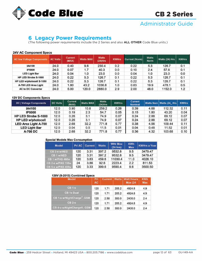
6 Legacy Power Requirements (The following power requirements include the 2 Series and also ALL OTHER Code Blue units.)

Code Blue • 259 Hedcor Street • Holland, MI 49423 USA • 800.205.7186 • www.codeblue.com GU-149-AApage 13 of 63
CB 2 SeriesAdministrator Guide

Code Blue • 259 Hedcor Street • Holland, MI 49423 USA • 800.205.7186 • www.codeblue.com GU-149-AApage 14 of 63
CB 2 SeriesAdministrator Guide
7 Software Configuration
Blue Alert® MNS Software
Blue Alert MNS (Mass Notification Software) fills a need in the marketplace for an incident response solution that is both comprehensive and cost-effective, while also providing an efficient way to detect and respond. The advanced mass notification system allows responders to deliver multi-layered emergency notifications via a wide range of platforms, including email, text message (SMS), emer-gency phones, public address speakers, social media, desktop alerts and more, quickly informing and directing people in emergency situations.
Blue Alert® EMS
Blue Alert EMS is an advanced software solution that handles all incoming events effectively by re-motely controlling emergency communication devices with an easy-to-use Graphical User Interface (GUI). You also will have the ability to open gates and AED access doors, turn LED beacon/strobes on or off, transfer calls to Public Address Systems to make area wide announcements and incor-porate other ancillary devices and applications while the system securely archives data for future reference.
ToolVox®
A sophisticated emergency management platform for your blue light phone network, ToolVox offers unique real-time monitoring and provisioning options for emergency phones and public address speakers, effectively acting as a hub for connecting Help Points® and other Code Blue devices. Us-ing our proprietary incident response software, Blue Alert® MNS and EMS, you can send alerts via outdoor platforms, such as blue light phones and public address speakers. It also provides connec-tions to PBX, public telephone (PSTN) and Internet (ISP) networks, in addition to third party security platforms.

Code Blue • 259 Hedcor Street • Holland, MI 49423 USA • 800.205.7186 • www.codeblue.com GU-149-AApage 15 of 63
CB 2 SeriesAdministrator Guide
8 CB 2-a Exploded View
DISCLAIMER: Product design and component use subject to change without notice. Product shown reasonably represents current offering and is intended to assist in component identification. Reference the model and serial number from the unit ID tag and contact manufacturer to confirm replacement part version and availability.
4
6
2
7
8
1
5
3
12
10
11
9
ITEM # DESCRIPTION QTY
1 Wall Mount Shell Assy 12 2 Series Wall Plate Assy 13 LED Faceplate Light 14 LED Blue Beacon Strobe 15 Standard / Custom Graphic 26 DIN Rail Assy 17 28” Harness, 4 Connector 18 28” Harness, 1 Connector 19 Lens 1
10 10-24 Nylock Nut 711 Lens Retainer Bracket Long 112 Lens Retainer Bracket Short 2

Code Blue • 259 Hedcor Street • Holland, MI 49423 USA • 800.205.7186 • www.codeblue.com GU-149-AApage 16 of 63
CB 2 SeriesAdministrator Guide
9 CB 2-e Exploded View
DISCLAIMER: Product design and component use subject to change without notice. Product shown reasonably represents current offering and is intended to assist in component identification. Reference the model and serial number from the unit ID tag and contact manufacturer to confirm replacement part version and availability.
5
3
2
6
7
1
4
11
9
10
8
ITEM # DESCRIPTION QTY
1 Wall Mount Shell Assy 12 2 Series Wall Plate Assy 13 LED Blue Beacon Strobe 14 Standard / Custom Graphic 25 DIN Rail Assy 16 28” Harness, 4 Connector 17 28” Harness, 1 Connector 18 Lens 19 10-24 Nylock Nut 7
10 Lens Retainer Bracket Long 111 Lens Retainer Bracket Short 1

Code Blue • 259 Hedcor Street • Holland, MI 49423 USA • 800.205.7186 • www.codeblue.com GU-149-AApage 17 of 63
CB 2 SeriesAdministrator Guide
10 Legacy CB 2-e Low Voltage Exploded View
DISCLAIMER: Product design and component use subject to change without notice. Product shown reasonably represents current offering and is intended to assist in component identification. Reference the model and serial number from the unit ID tag and contact manufacturer to confirm replacement part version and availability.
3
2
4
44
1
4
5
9
8
7
6
4
10
3
2
4
44
1
4
5
9
8
7
6
4
10
BALL # PART # DESCRIPTION
1 41425 HID Lens2 40159 LED Beacon Strobe3 41500 Button head Security Screw (3 pk)4 40102 Wall Anchor Kit5 41471 Analog Surge Suppressor5 41421 IP Surge Suppressor6 CALL Standard / Custom Graphic7 50001 Single Button IA4100 Analog Phone – PUSH FOR HELP7 50002 Double Button IA4100 Analog Phone – PUSH FOR HELP7 50003 Keypad IA4100 Analog Phone – PUSH FOR HELP7 50004 Single Button IA4100 Analog Phone – EMERGENCY7 50005 Double Button IA4100 Analog Phone – EMERGENCY7 50006 Keypad IA4100 Analog Phone – EMERGENCY7 50101 Single Button IP5000 VoIP Phone – PUSH FOR HELP
BALL # PART # DESCRIPTION
7 50102 Double Button IP5000 VoIP Phone – PUSH FOR HELP7 50103 Keypad IP5000 VoIP Phone – PUSH FOR HELP7 50104 Single Button IP5000 VoIP Phone – EMERGENCY7 50105 Double Button IP5000 VoIP Phone – EMERGENCY7 50106 Keypad IP5000 VoIP Phone – EMERGENCY8 41544 Faceplate Security Screw 10x24 (6 pk)9 40101 Manifold R/B 5-way
10 40357 Bezel Assembly IA4100 Analog Phone – PUSH FOR HELP10 40407 Bezel Assembly IA4100 Analog Phone – EMERGENCY10 40313 Bezel Assembly IP5000 VoIP Phone – PUSH FOR HELP10 40405 Bezel Assembly IP5000 VoIP Phone – EMERGENCY
Code Blue • 259 Hedcor Street • Holland, MI 49423 USA • 800.205.7186 • www.codeblue.com GU-149-AApage 18 of 63
CB 2 SeriesAdministrator Guide
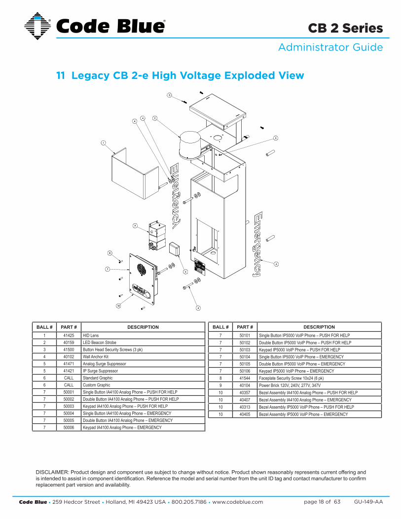
11 Legacy CB 2-e High Voltage Exploded View
DISCLAIMER: Product design and component use subject to change without notice. Product shown reasonably represents current offering and is intended to assist in component identification. Reference the model and serial number from the unit ID tag and contact manufacturer to confirm replacement part version and availability.
3
2
3
44
1
4
9
8
7
6
10
5
3
2
3
44
1
4
9
8
7
6
10
5
BALL # PART # DESCRIPTION
1 41425 HID Lens2 40159 LED Beacon Strobe3 41500 Button Head Security Screws (3 pk)4 40102 Wall Anchor Kit5 41471 Analog Surge Suppressor5 41421 IP Surge Suppressor6 CALL Standard Graphic6 CALL Custom Graphic7 50001 Single Button IA4100 Analog Phone – PUSH FOR HELP7 50002 Double Button IA4100 Analog Phone – PUSH FOR HELP7 50003 Keypad IA4100 Analog Phone – PUSH FOR HELP7 50004 Single Button IA4100 Analog Phone – EMERGENCY7 50005 Double Button IA4100 Analog Phone – EMERGENCY7 50006 Keypad IA4100 Analog Phone – EMERGENCY
BALL # PART # DESCRIPTION
7 50101 Single Button IP5000 VoIP Phone – PUSH FOR HELP7 50102 Double Button IP5000 VoIP Phone – PUSH FOR HELP7 50103 Keypad IP5000 VoIP Phone – PUSH FOR HELP7 50104 Single Button IP5000 VoIP Phone – EMERGENCY7 50105 Double Button IP5000 VoIP Phone – EMERGENCY7 50106 Keypad IP5000 VoIP Phone – EMERGENCY8 41544 Faceplate Security Screw 10x24 (6 pk)9 40104 Power Brick 120V, 240V, 277V, 347V10 40357 Bezel Assembly IA4100 Analog Phone – PUSH FOR HELP10 40407 Bezel Assembly IA4100 Analog Phone – EMERGENCY10 40313 Bezel Assembly IP5000 VoIP Phone – PUSH FOR HELP10 40405 Bezel Assembly IP5000 VoIP Phone – EMERGENCY

Code Blue • 259 Hedcor Street • Holland, MI 49423 USA • 800.205.7186 • www.codeblue.com GU-149-AApage 19 of 63
CB 2 SeriesAdministrator Guide
12 CB 2-s Low Voltage Exploded View
DISCLAIMER: Product design and component use subject to change without notice. Product shown reasonably represents current offering and is intended to assist in component identification. Reference the model and serial number from the unit ID tag and contact manufacturer to confirm replacement part version and availability.
9
3
7
10
4
14
5
6
8
2
1
13
12
11
BALL # PART # DESCRIPTION
1 40357 Bezel Assembly IA4100 Analog Phone – PUSH FOR HELP1 40407 Bezel Assembly IA4100 Analog Phone – EMERGENCY1 40313 Bezel Assembly IP5000 VoIP Phone – PUSH FOR HELP1 40405 Bezel Assembly IP5000 VoIP Phone – EMERGENCY2 50001 Single Button IA4100 Analog Phone – PUSH FOR HELP2 50002 Double Button IA4100 Analog Phone – PUSH FOR HELP2 50003 Keypad IA4100 Analog Phone – PUSH FOR HELP2 50004 Single Button IA4100 Analog Phone – EMERGENCY2 50005 Double Button IA4100 Analog Phone – EMERGENCY2 50006 Keypad IA4100 Analog Phone – EMERGENCY2 50101 Single Button IP5000 VoIP Phone – PUSH FOR HELP2 50102 Double Button IP5000 VoIP Phone – PUSH FOR HELP2 50103 Keypad IP5000 VoIP Phone – PUSH FOR HELP2 50104 Single Button IP5000 VoIP Phone – EMERGENCY
BALL # PART # DESCRIPTION
2 50105 Double Button IP5000 VoIP Phone – EMERGENCY2 50106 Keypad IP5000 VoIP Phone – EMERGENCY3 41544 Faceplate Security Screw 10x24 (6 pk)4 41548 LED Faceplate Light5 CALL Standard / Custom Graphic6 41471 Analog Surge Suppressor6 41421 IP Surge Suppressor7 41539 LED Area Light8 41544 Faceplate Security Screw 10x24 (6 pk)9 41412 HID Lens10 40159 LED Blue Beacon Strobe11 40543 Strobe Disk (3 pk)12 10084 Clear Strobe Spacer13 40102 Wall Mount Hardware Kit14 40101 Manifold R/B 5-way
Code Blue • 259 Hedcor Street • Holland, MI 49423 USA • 800.205.7186 • www.codeblue.com GU-149-AApage 20 of 63
CB 2 SeriesAdministrator Guide
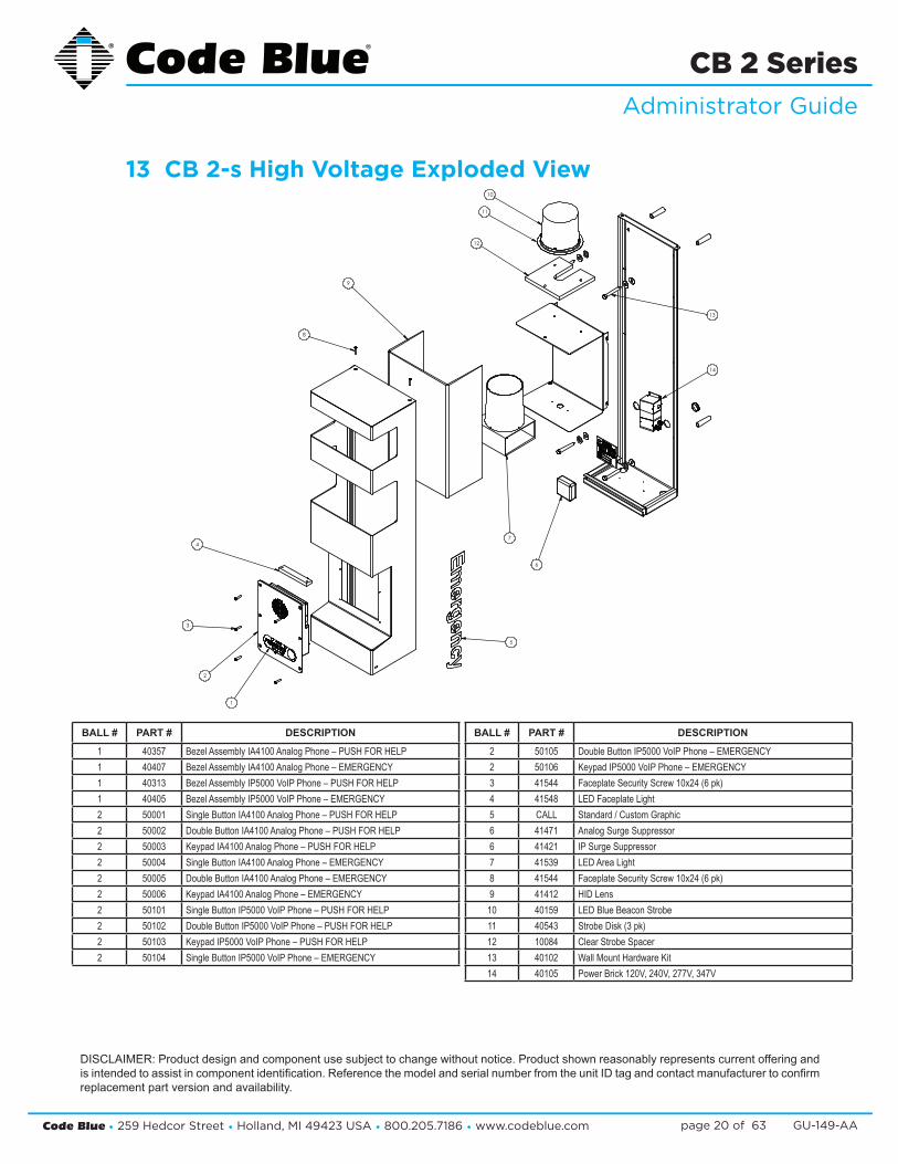
13 CB 2-s High Voltage Exploded View
DISCLAIMER: Product design and component use subject to change without notice. Product shown reasonably represents current offering and is intended to assist in component identification. Reference the model and serial number from the unit ID tag and contact manufacturer to confirm replacement part version and availability.
9
3
7
10
4
14
5
6
8
2
1
13
12
11
BALL # PART # DESCRIPTION
1 40357 Bezel Assembly IA4100 Analog Phone – PUSH FOR HELP1 40407 Bezel Assembly IA4100 Analog Phone – EMERGENCY1 40313 Bezel Assembly IP5000 VoIP Phone – PUSH FOR HELP1 40405 Bezel Assembly IP5000 VoIP Phone – EMERGENCY2 50001 Single Button IA4100 Analog Phone – PUSH FOR HELP2 50002 Double Button IA4100 Analog Phone – PUSH FOR HELP2 50003 Keypad IA4100 Analog Phone – PUSH FOR HELP2 50004 Single Button IA4100 Analog Phone – EMERGENCY2 50005 Double Button IA4100 Analog Phone – EMERGENCY2 50006 Keypad IA4100 Analog Phone – EMERGENCY2 50101 Single Button IP5000 VoIP Phone – PUSH FOR HELP2 50102 Double Button IP5000 VoIP Phone – PUSH FOR HELP2 50103 Keypad IP5000 VoIP Phone – PUSH FOR HELP2 50104 Single Button IP5000 VoIP Phone – EMERGENCY
BALL # PART # DESCRIPTION
2 50105 Double Button IP5000 VoIP Phone – EMERGENCY2 50106 Keypad IP5000 VoIP Phone – EMERGENCY3 41544 Faceplate Security Screw 10x24 (6 pk)4 41548 LED Faceplate Light5 CALL Standard / Custom Graphic6 41471 Analog Surge Suppressor6 41421 IP Surge Suppressor7 41539 LED Area Light8 41544 Faceplate Security Screw 10x24 (6 pk)9 41412 HID Lens10 40159 LED Blue Beacon Strobe11 40543 Strobe Disk (3 pk)12 10084 Clear Strobe Spacer13 40102 Wall Mount Hardware Kit14 40105 Power Brick 120V, 240V, 277V, 347V
Code Blue • 259 Hedcor Street • Holland, MI 49423 USA • 800.205.7186 • www.codeblue.com GU-149-AApage 21 of 63
CB 2 SeriesAdministrator Guide
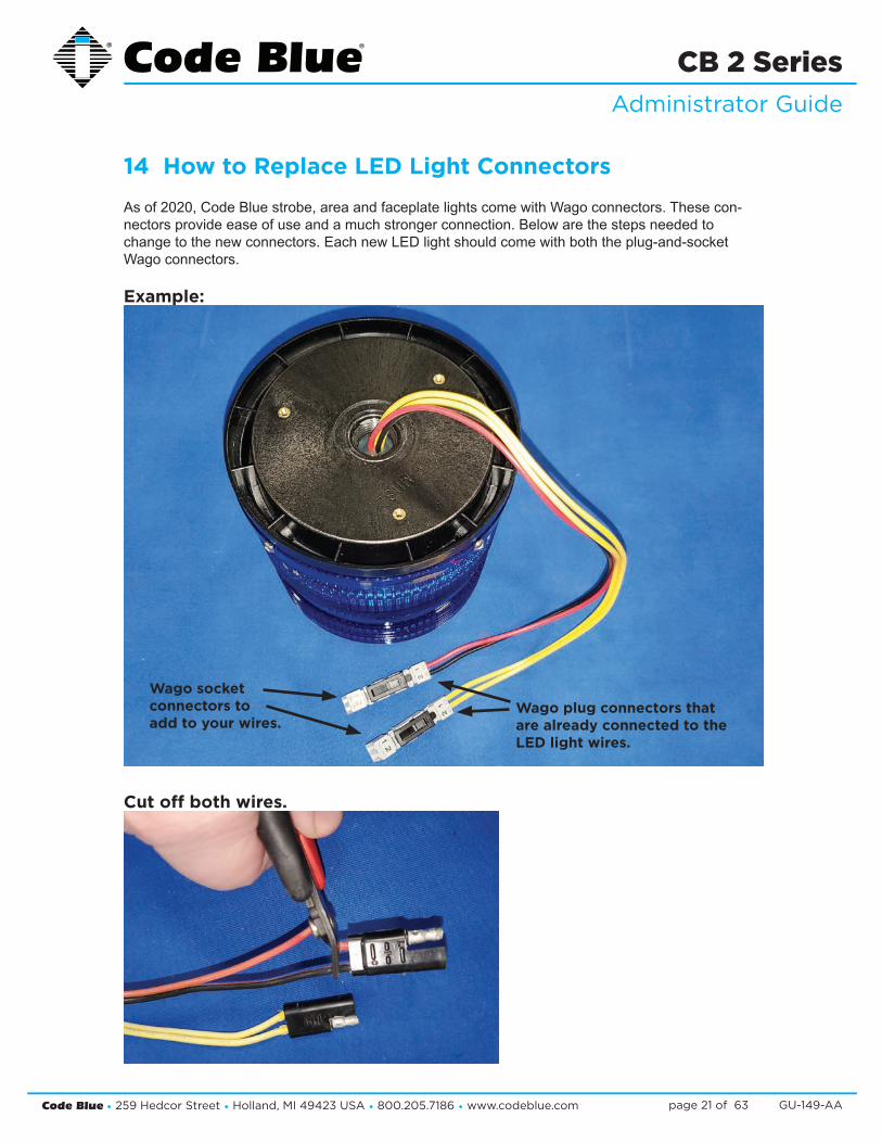
14 How to Replace LED Light Connectors
As of 2020, Code Blue strobe, area and faceplate lights come with Wago connectors. These con-nectors provide ease of use and a much stronger connection. Below are the steps needed to change to the new connectors. Each new LED light should come with both the plug-and-socket Wago connectors.
Example:
Cut off both wires.
Wago plug connectors that are already connected to the LED light wires.
Wago socket connectors to add to your wires.

Code Blue • 259 Hedcor Street • Holland, MI 49423 USA • 800.205.7186 • www.codeblue.com GU-149-AApage 22 of 63
CB 2 SeriesAdministrator Guide
Strip all wires and twist tight.
Place small screwdriver into square hole and push down. Insert cut wire into round hole and remove screwdriver. Repeat on the rest of the connectors.
Once all connectors have been switched, you are ready to apply power to the LED.
This will work on strobe, area and faceplate lights.Please contact [email protected] if you need further assistance.

Code Blue • 259 Hedcor Street • Holland, MI 49423 USA • 800.205.7186 • www.codeblue.com GU-149-AApage 23 of 63
CB 2 SeriesAdministrator Guide
Legal Considerations
Video and audio surveillance can be regulated by laws that vary from country to country. Check the laws in your local region before using this product for surveillance purposes.
Liability
Every care has been taken in the preparation of this document. Please inform Code Blue Corporation of any inaccuracies or omis-sions. Code Blue cannot be held responsible for any technical or typographical errors and reserves the right to make changes to the product and manuals without prior notice. Code Blue makes no warranty of any kind with regard to the material contained within this document, including, but not limited to, the implied warranties of merchantability and fitness for a particular purpose. Code Blue shall not be liable or responsible for incidental or consequential damages in connection with the furnishing, performance or use of this mate-rial. This product is only to be used for its intended purpose.
Intellectual Property Rights
Code Blue Corporation has intellectual property rights relating to technology embodied in the product described in this document. This product contains open source code that also contains ad-ditional open source libraries.
Equipment Modifications
This equipment must be installed and used in strict accordance with the instructions given in the user documentation. This equipment contains no user-serviceable components. Unauthorized equipment changes or modifications will invalidate all applicable regulatory certifications and approvals.
Trademark Acknowledgments
Code Blue and Centry products are registered trademarks or trademark applications of Code Blue Corporation in various jurisdic-tions. All other company names and products are trademarks or registered trademarks of their respective companies.
Regulatory Information
Electromagnetic Compatibility (EMC)This equipment has been designed and tested to fulfill applicable standards for:
• Radio frequency emission when installed according to the instructions and used in the intended environment.
• Immunity to electrical and electromagnetic phenomenon when installed according to the instructions and used in its intended environment.
USA
This equipment has been tested using a shielded network cable (STP) and found to comply with the limits for a Class A digital device, pursuant to part 15 of the FCC Rules. These limits are designed to provide reasonable protection against harmful interfer-ence when the equipment is operated in a commercial environment. This equipment generates, uses and can radiate radio frequency energy and, if not installed and used in accordance with the instruc-tion manual, may cause harmful interference to radio communica-tions. Operation of this equipment in a residential area is likely to cause harmful interference in which case the user will be required to correct the interference at their own expense. The product shall be connected using a shielded network cable (STP) that is properly grounded.
Canada
This digital apparatus complies with CAN ICES-3 (Class A). The product shall be connected using a shielded network cable (STP) that is properly grounded. Cet appareil numérique est conforme à la norme NMB ICES-3 (classe A). Le produit doit être connecté à l’aide d’un câble réseau blindé (STP) qui est correctement mis à la terre.Safety
This product complies with 62638-1 Safety of Information Technol-ogy Equipment. The product shall be grounded either through a shielded network cable (STP) or other appropriate method. The power supply used with this product shall fulfill the requirements for Safety Extra Low Voltage (SELV) and Limited Power Source (LPS) according to IEC/EN/UL 60950-1. This unit complies with IP54/NEMA 3 and IEC 61969-3 Class 1 specifications.
Warranty
Code Blue Corporation provides a limited warranty on this product. Refer to your sales agreement to establish the terms. In addition, Code Blue’s standard warranty language, as well as information regarding support for this product while under warranty, is available at www.codeblue.com/support/downloads.
In Case of Breakdown
In case of system breakdown, discontinue use and contact Tech Support at [email protected] or call (800) 205-7186, option 3.
In Case of Abnormal Operation
If the unit emits smoke or an unusual smell, if water or other foreign material enters the enclosure, or if you drop the unit or damage the enclosure, power off the unit immediately and contact:
Code Blue Customer Service at [email protected] or (800) 205-7186, option 2.
Disposal and Recycling
When this product has reached the end of its useful life, dispose of it according to local laws and regulations. For information about your nearest designated collection point, contact your local authority responsible for waste disposal. In accordance with local legislation, penalties may be applicable for incorrect disposal of this waste.
This guide should contain all the information needed for your application. If any further information is needed, please contact [email protected].
Support
Should you require any technical assistance, please contact Code Blue. Visit codeblue.com to:
• Download user documentation and software. • Find answers to resolved problems in the FAQ database.• Report problems to Code Blue Technical Support via email
at [email protected] or 800-205-7186.
15 CB 2-a Installation Instructions

Code Blue • 259 Hedcor Street • Holland, MI 49423 USA • 800.205.7186 • www.codeblue.com GU-149-AApage 24 of 63
CB 2 SeriesAdministrator Guide
Tools needed for installation:
1. Drill 2. Drill bit (5/8” Masonry bit for concrete; 1/2” standard bit for wood)3. 3/8” Hex head driver bit4. Level
Basic installation instructions:
1. Unscrew security screw from bottom of unit. Lift and open unit.2. Disconnect wire connections from strobe, faceplate light and phone. Lift up on black locking
tab on each connector to separate. 3. Unscrew the nut from the stud to release safety cable from back plate. Place nut back on
stud.4. Lift up on front of unit and remove. Set aside.5. Using back plate of unit as template, level and mark the four mounting holes.6. Drill all marked holes with appropriate drill bit. 7. If attaching to concrete or brick, insert one 3/8” anchor into each drilled hole. 8. If attaching to wood, 3/8” lag bolt is required.9. On one 3/8x3” lag bolt, add one 3/8” flat stainless steel washer followed by one 3/8” flat rub-
ber washer.10. Slide lag bolt through top left mounting hole.11. Add one 3/8” flat rubber washer, followed by one 3/8” flat stainless steel washer to end of
screw.12. Drill lag bolt into mounting hole. 13. Repeat previous steps for three remaining mounting holes.14. Slide front of unit back onto bottom tabs of back plate.15. Reattach safety cable.16. Reconnect strobe, faceplate light and phone to power system.17. Connect incoming power to appropriate tap (high voltage or low voltage).18. Connect incoming communication line (CAT6) to phone using its WAN port.19. Close unit. 20. Replace security screw into bottom of unit.

Code Blue • 259 Hedcor Street • Holland, MI 49423 USA • 800.205.7186 • www.codeblue.com GU-149-AApage 25 of 63
CB 2 SeriesAdministrator Guide
Mounting Schematics
1.25
1.8
0
9.8
0
2.21
28.21
1.3
0
10.
30
1.3
0
10.
30
26.00
9.00

Code Blue • 259 Hedcor Street • Holland, MI 49423 USA • 800.205.7186 • www.codeblue.com GU-149-AApage 26 of 63
CB 2 SeriesAdministrator Guide
Legal Considerations
Video and audio surveillance can be regulated by laws that vary from country to country. Check the laws in your local region before using this product for surveillance purposes.
Liability
Every care has been taken in the preparation of this document. Please inform Code Blue Corporation of any inaccuracies or omis-sions. Code Blue cannot be held responsible for any technical or typographical errors and reserves the right to make changes to the product and manuals without prior notice. Code Blue makes no warranty of any kind with regard to the material contained within this document, including, but not limited to, the implied warranties of merchantability and fitness for a particular purpose. Code Blue shall not be liable or responsible for incidental or consequential damages in connection with the furnishing, performance or use of this mate-rial. This product is only to be used for its intended purpose.
Intellectual Property Rights
Code Blue Corporation has intellectual property rights relating to technology embodied in the product described in this document. This product contains open source code that also contains ad-ditional open source libraries.
Equipment Modifications
This equipment must be installed and used in strict accordance with the instructions given in the user documentation. This equipment contains no user-serviceable components. Unauthorized equipment changes or modifications will invalidate all applicable regulatory certifications and approvals.
Trademark Acknowledgments
Code Blue and Centry products are registered trademarks or trademark applications of Code Blue Corporation in various jurisdic-tions. All other company names and products are trademarks or registered trademarks of their respective companies.
Regulatory Information
Electromagnetic Compatibility (EMC)This equipment has been designed and tested to fulfill applicable standards for:
• Radio frequency emission when installed according to the instructions and used in the intended environment.
• Immunity to electrical and electromagnetic phenomenon when installed according to the instructions and used in its intended environment.
USA
This equipment has been tested using a shielded network cable (STP) and found to comply with the limits for a Class A digital device, pursuant to part 15 of the FCC Rules. These limits are designed to provide reasonable protection against harmful interfer-ence when the equipment is operated in a commercial environment. This equipment generates, uses and can radiate radio frequency energy and, if not installed and used in accordance with the instruc-tion manual, may cause harmful interference to radio communica-tions. Operation of this equipment in a residential area is likely to cause harmful interference in which case the user will be required to correct the interference at their own expense. The product shall be connected using a shielded network cable (STP) that is properly grounded.
Canada
This digital apparatus complies with CAN ICES-3 (Class A). The product shall be connected using a shielded network cable (STP) that is properly grounded. Cet appareil numérique est conforme à la norme NMB ICES-3 (classe A). Le produit doit être connecté à l’aide d’un câble réseau blindé (STP) qui est correctement mis à la terre.Safety
This product complies with 62638-1 Safety of Information Technol-ogy Equipment. The product shall be grounded either through a shielded network cable (STP) or other appropriate method. The power supply used with this product shall fulfill the requirements for Safety Extra Low Voltage (SELV) and Limited Power Source (LPS) according to IEC/EN/UL 60950-1. This unit complies with IP54/NEMA 3 and IEC 61969-3 Class 1 specifications.
Warranty
Code Blue Corporation provides a limited warranty on this product. Refer to your sales agreement to establish the terms. In addition, Code Blue’s standard warranty language, as well as information regarding support for this product while under warranty, is available at www.codeblue.com/support/downloads.
In Case of Breakdown
In case of system breakdown, discontinue use and contact Tech Support at [email protected] or call (800) 205-7186, option 3.
In Case of Abnormal Operation
If the unit emits smoke or an unusual smell, if water or other foreign material enters the enclosure, or if you drop the unit or damage the enclosure, power off the unit immediately and contact:
Code Blue Customer Service at [email protected] or (800) 205-7186, option 2.
Disposal and Recycling
When this product has reached the end of its useful life, dispose of it according to local laws and regulations. For information about your nearest designated collection point, contact your local authority responsible for waste disposal. In accordance with local legislation, penalties may be applicable for incorrect disposal of this waste.
This guide should contain all the information needed for your application. If any further information is needed, please contact [email protected].
Support
Should you require any technical assistance, please contact Code Blue. Visit codeblue.com to:
• Download user documentation and software. • Find answers to resolved problems in the FAQ database.• Report problems to Code Blue Technical Support via email
at [email protected] or 800-205-7186.
16 CB 2-e Installation Instructions

Code Blue • 259 Hedcor Street • Holland, MI 49423 USA • 800.205.7186 • www.codeblue.com GU-149-AApage 27 of 63
CB 2 SeriesAdministrator Guide
Tools needed for installation:
1. Drill 2. Drill bit (5/8” Masonry bit for concrete; 1/2” standard bit for wood)3. 3/8” Hex head driver bit4. Level
Basic installation instructions:
21. Unscrew security screw from bottom of unit. Lift and open unit.22. Disconnect wire connections from strobe, faceplate light and phone. Lift up on black locking
tab on each connector to separate. 23. Unscrew the nut from the stud to release safety cable from back plate. Place nut back on
stud.24. Lift up on front of unit and remove. Set aside.25. Using back plate of unit as template, level and mark the four mounting holes.26. Drill all marked holes with appropriate drill bit. 27. If attaching to concrete or brick, insert one 3/8” anchor into each drilled hole. 28. If attaching to wood, 3/8” lag bolt is required.29. On one 3/8x3” lag bolt, add one 3/8” flat stainless steel washer followed by one 3/8” flat rub-
ber washer.30. Slide lag bolt through top left mounting hole.31. Add one 3/8” flat rubber washer, followed by one 3/8” flat stainless steel washer to end of
screw.32. Drill lag bolt into mounting hole. 33. Repeat previous steps for three remaining mounting holes.34. Slide front of unit back onto bottom tabs of back plate.35. Reattach safety cable.36. Reconnect strobe and phone to power system.37. Connect incoming power to appropriate tap (high voltage or low voltage).38. Connect incoming communication line (CAT6) to phone using its WAN port.39. Close unit. 40. Replace security screw into bottom of unit.

Code Blue • 259 Hedcor Street • Holland, MI 49423 USA • 800.205.7186 • www.codeblue.com GU-149-AApage 28 of 63
CB 2 SeriesAdministrator Guide
Mounting Schematics
1.25
1.8
0
9.8
0
2.21
28.21
1.3
0
10.
30
1.3
0
10.
30
26.00
9.00

Code Blue • 259 Hedcor Street • Holland, MI 49423 USA • 800.205.7186 • www.codeblue.com GU-149-AApage 29 of 63
CB 2 SeriesAdministrator Guide
17 Legacy CB 2-e Installation Instructions
1.0 PRE-INSTALLATION
1.1 Electrical preparation – The unit may have supply wires run from either (a) behind the unit through the wall, or (b) below the unit using an external conduit through the bottom of the unit. Holes in the back and bottom of the unit have been provided for this purpose.
2.0 INSTALLATION PROCEDURES
2.1 Remove the top of the unit.
2.2 Mark the mounting holes – In order to comply with the Americans with Disabilities Act (ADA) of 1990, the speakerphone button(s) should be positioned between 34 and 48 inches from grade level. (Consult an ADA specialist in your area to verify local and federal guide-lines.)
2.3 Drill all marked holes.
2.4 Install the housing – Four anchors of appropriate size and type should be used to fasten the housing to the wall.
IMPORTANT: If wiring is supplied from the back, ensure that the conduit is aligned at this time.
2.5 Reattach the top.
3.0 WIRING
3.1 Ground – The ground (green) wire should be stripped and fastened to the supplied ground-ing lug.
3.2 24V AC supply – The unit will contain a 5 finger manifold with corresponding fuses per component. Incoming power is connected to the red and black wires on the manifold.
3.3 120/240V AC supply – The unit will contain a small 120V AC 40VA transformer. The incom-ing power would run to the two forks coming off of the transformer and power is distributed through the 5 finger manifold.
3.4 120,240,277V AC Multi-tap transformer – Incoming power will be connected to the trans-former and wiring will depend on incoming voltage. A wiring diagram depicting each voltage option is located on top of the multi-tap transformer. Power will be distributed through the multiple fingers coming off the transformer.
3.5 PoE Power – The unit will contain a PoE splitter and an IP surge suppressor. The incoming RJ45 connector would run to the IP surge suppressor inside the unit. A CAT 5 cable from the surge suppressor runs to the PoE splitter. All power in the unit is distributed through the PoE splitter.
See diagrams next page

Code Blue • 259 Hedcor Street • Holland, MI 49423 USA • 800.205.7186 • www.codeblue.com GU-149-AApage 30 of 63
CB 2 SeriesAdministrator Guide

Code Blue • 259 Hedcor Street • Holland, MI 49423 USA • 800.205.7186 • www.codeblue.com GU-149-AApage 31 of 63
CB 2 SeriesAdministrator Guide
Suggested installation dimensions shown from ground to lower right mounting hole are for single button face-plates.
• For dual button faceplate, deduct 3.25 inches.• For keypad faceplate, deduct 4.5 inches.• For wheelchair direct facing access only, deduct 6 inches.
DISCLAIMER: The dimensions above are intended as guidelines only. For specific installation requirements, reference your local codes.
All wiring must be installed and connected by experienced and certified personnel to meetlocal and national electrical codes, and will include a service disconnect.

Code Blue • 259 Hedcor Street • Holland, MI 49423 USA • 800.205.7186 • www.codeblue.com GU-149-AApage 32 of 63
CB 2 SeriesAdministrator Guide
See diagrams next page
1.0 PRE-INSTALLATION
1.1 Electrical preparation – The unit may have supply wires run from either (a) behind the unit through the wall, or (b) below the unit using an external conduit through the bottom of the unit. Holes in the back and bottom of the unit have been provided for this purpose.
2.0 INSTALLATION PROCEDURES
2.1 Remove the top of the unit.
2.2 Mark the mounting holes – In order to comply with the Americans with Disabilities Act (ADA) of 1990, the speakerphone button(s) should be positioned between 34 and 48 inches from grade level. (Consult an ADA specialist in your area to verify local and federal guidelines.)
2.3 Drill all marked holes.
2.4 Install the housing – Four anchors of appropriate size and type should be used to fasten the housing to the wall.
IMPORTANT: If wiring is supplied from the back, ensure that the conduit is aligned at this time.
2.5 Reattach the top.
3.0 ELECTRICAL WIRING
3.1 Ground – The ground (green) wire should be stripped and fastened to the supplied grounding lug.
3.2 24V AC supply – The unit will contain a 5 finger manifold with corresponding fuses per component. Incoming power is connected to the red and black wires on the manifold.
3.3 120/240V AC supply – The unit will contain a small 120V AC 40VA transformer. The incom-ing power would run to the two forks coming off of the transformer and power is distributed through the 5 finger manifold.
3.4 120,240,277V AC Multi-tap transformer – Incoming power will be connected to the trans-former and wiring will depend on incoming voltage. A wiring diagram depicting each voltage option is located on top of the multi-tap transformer. Power will be distributed through the multiple fingers coming off the transformer.
3.5 PoE Power – The unit will contain a PoE splitter and an IP surge suppressor. The incoming RJ45 connector would run to the IP surge suppressor inside the unit. A CAT 5 cable from the surge suppressor runs to the PoE splitter. All power in the unit is distributed through the PoE splitter.
4.0 COMMUNICATIONS WIRING
4.1 Have category 3 or higher 4-pair cable terminated to a RJ45 applying TIA/EIA T568-B speci-fications.
18 Legacy CB 2-e with Public Address Installation Instructions

Code Blue • 259 Hedcor Street • Holland, MI 49423 USA • 800.205.7186 • www.codeblue.com GU-149-AApage 33 of 63
CB 2 SeriesAdministrator Guide

Code Blue • 259 Hedcor Street • Holland, MI 49423 USA • 800.205.7186 • www.codeblue.com GU-149-AApage 34 of 63
CB 2 SeriesAdministrator Guide
Suggested installation dimensions shown from ground to lower right mounting hole are for single button face-plates.
• For dual button faceplate, deduct 3.25 inches.• For keypad faceplate, deduct 4.5 inches.• For wheelchair direct facing access only, deduct 6 inches.
DISCLAIMER: The dimensions above are intended as guidelines only. For specific installation requirements, reference your local codes.
All wiring must be installed and connected by experienced and certified personnel to meetlocal and national electrical codes, and will include a service disconnect.

Code Blue • 259 Hedcor Street • Holland, MI 49423 USA • 800.205.7186 • www.codeblue.com GU-149-AApage 35 of 63
CB 2 SeriesAdministrator Guide
1.0 PRE-INSTALLATION
1.1 Electrical preparation – The unit may have supply wires run from either (a) behind the unit through the wall, or (b) below the unit using an external conduit through the bottom of the unit. Holes in the back and bottom of the unit have been provided for this purpose (see Figure 1).
2.0 INSTALLATION PROCEDURES
2.1 Remove the top of the unit.
2.2 Mark the mounting holes – In order to comply with the Americans with Disabilities Act (ADA) of 1990, the speakerphone button(s) should be positioned between 34 and 48 inches from grade level. (Consult an ADA specialist in your area to verify local and federal guide-lines.)
2.3 Drill all marked holes.
2.4 Install the housing – Four anchors of appropriate size and type should be used to fasten the housing to the wall.
IMPORTANT: If wiring is supplied from the back, ensure that the conduit is aligned at this time.
2.5 Reattach the top.
3.0 WIRING
3.1 120/240V AC supply – Feed the incoming power leads into the supplied J-Box. Connect the ground to the supplied grounding lug. Connect the neutral to the orange lead for fusing the unit. Connect the load to the black wires. After completing the wire connections, install the supplied J-Box cover and ensure all cord grips are secure.
See diagrams next page
19 Legacy CB 2-e with AED Housing Installation Instructions

Code Blue • 259 Hedcor Street • Holland, MI 49423 USA • 800.205.7186 • www.codeblue.com GU-149-AApage 36 of 63
CB 2 SeriesAdministrator Guide
11
23.06
15.5
12.53
9.00
3.00
36.00
21.00
8.00
46.72

Code Blue • 259 Hedcor Street • Holland, MI 49423 USA • 800.205.7186 • www.codeblue.com GU-149-AApage 37 of 63
CB 2 SeriesAdministrator Guide
Suggested installation dimensions shown from ground to lower right mounting hole are for single button face-plates.
• For dual button faceplate, deduct 3.25 inches.• For keypad faceplate, deduct 4.5 inches.• For wheelchair direct facing access only, deduct 6 inches.
DISCLAIMER: The dimensions above are intended as guidelines only. For specific installation requirements, reference your local codes.
All wiring must be installed and connected by experienced and certified personnel to meetlocal and national electrical codes, and will include a service disconnect.
28.00
BOTTOM
GROUND LEVEL
3.00
36.00
21.00
9.00
8.00
12.40
Ø .44 MOUNTING HOLES4 PLCS
Ø 1.13KNOCKOUTS FOR Ø 3/4 CONDUIT
2 PLCS
45.22
Ø 1.13THRU BOTTOM PLATE FOR Ø 3/4 CONDUIT
2 PLCS
8.002.20REF
1.62MOUNTING SURFACE

Code Blue • 259 Hedcor Street • Holland, MI 49423 USA • 800.205.7186 • www.codeblue.com GU-149-AApage 38 of 63
CB 2 SeriesAdministrator Guide
20 CB 2-s Installation Instructions
1.0 PRE-INSTALLATION
1.1 Running the wires – Wires to the unit may be run either (a) from behind the unit through the wall, or (b) from below the unit using an external conduit through the bottom of the unit’s back plate. Holes in the back and bottom of the unit have been provided for this purpose.
2.0 INSTALLATION PROCEDURES
2.1 Remove the light bracket and outer shell from the back plate.
2.2 Mark the mounting holes – In order to comply with the Americans with Disabilities Act (ADA) of 1990, the speakerphone button(s) should be positioned between 34 and 48 inches from grade level. (Consult an ADA specialist in your area to verify local and federal guide-lines.)
2.3 Install the back plate – Four anchors should securely fasten the back plate to the wall.
IMPORTANT: If wiring is coming in from the back, ensure that the conduit is aligned at this time.
2.4 Reattach the light bracket.
2.5 Reattach the outer shell – Holding the shell horizontal, hook the bottom hinge into the bot-tom of the back plate. Swing the shell up and fasten the safety cable to the eyehook.
2.6 Connect electrical and communications wiring (see wiring instructions).
2.7 Close the unit – Fasten the outer shell to the back plate using two #10 countersunk secu-rity screws.
See diagrams next page

Code Blue • 259 Hedcor Street • Holland, MI 49423 USA • 800.205.7186 • www.codeblue.com GU-149-AApage 39 of 63
CB 2 SeriesAdministrator Guide

Code Blue • 259 Hedcor Street • Holland, MI 49423 USA • 800.205.7186 • www.codeblue.com GU-149-AApage 40 of 63
CB 2 SeriesAdministrator Guide
Suggested installation dimensions shown from ground to lower right mounting hole are for single button face-plates.
• For dual button faceplate, deduct 3.25 inches.• For keypad faceplate, deduct 4.5 inches.• For wheelchair direct facing access only, deduct 6 inches.
DISCLAIMER: The dimensions above are intended as guidelines only. For specific installation requirements, reference your local codes.
30 3/430 3/4
4343
2 9/162 9/16
66 1 1/21 1/2
12 REF12 REF
99
GROUND/FLOORGROUND/FLOOR
4 X Ø7/16 MOUNTING HOLES4 X Ø7/16 MOUNTING HOLES
2 X Ø1-1/82 X Ø1-1/8(KNOCKOUTS FOR (KNOCKOUTS FOR
Ø3/4 CONDUIT)Ø3/4 CONDUIT)
42 REF42 REF
8 5/16 REF8 5/16 REF
1 1/2 REF1 1/2 REF
All wiring must be installed and connected by experienced and certified personnel to meetlocal and national electrical codes, and will include a service disconnect.

Code Blue • 259 Hedcor Street • Holland, MI 49423 USA • 800.205.7186 • www.codeblue.com GU-149-AApage 41 of 63
CB 2 SeriesAdministrator Guide
21 Pole Mount Bracket Installation Instructions
1.0 THREAD MOUNTING STRAPS THROUGH SLOTS1.1 Thread mounting straps through slots for any size poles.
2.0 HOLD BRACKET TO POLE2.1 Set the height of the bracket (C) so that the speakerphone push button(s) on the unit will be
at desired height (please check with local codes for ADA compliance).
3.0 BAND THE BRACKET TO THE POLE AT DESIRED HEIGHT3.1 To eliminate waste, pull band (A) from carton as needed. With ears of buckle (B) away from
operator, slide the buckle on the banding. Lace banding around the object being clamped and again through buckle.
3.2 Bend end of band under buckle.3.3 Slide band into banding tool nose slot.3.4 When maximum tension has been reached, roll tool over buckle. At same time reversing
handle carefully approximately ¾ turn to avoid breakage. The band that is released will be used in the bend and therefore there is no loss of tension.
3.5 Lift cutter lever and band will be cut to correct length.While holding the stub of the band with your thumb, hammer flat over bridge of buckle.
3.6 Complete application by hammering the buckle ears over the stub.
4.0 ATTACH ENCLOSURE TO BRACKET4.1 Place a rubber washer (D) on each of the four studs.4.2 Align and place the back plate of the unit over the four studs.4.3 Place a second set of rubber washers on to each of the four studs (inside the unit).4.4 Place a steel washer (E) on each of the four studs.4.5 Turn a nut (F) on each of the four studs.
Banding tool sold separately on the Parts Order Form, part #41441.
1.0 THREAD MOUNTING STRAPS THROUGH SLOTS
1.1 Use outside slots for larger poles and inside slots for smaller poles.
2.0 HOLD BRACKET TO POLE
2.1 Set the height of the bracket (C) so that the speakerphone push button(s) on the unit will be at desired height (please check with local codes for ADA compliance).
3.0 BAND THE BRACKET TO THE POLE AT DESIRED HEIGHT
3.1 To eliminate waste, pull band (A) from carton as needed. With ears of buckle (B) away from operator, slide the buckle on the banding. Lace banding around the object being clamped and again through buckle.
3.2 Bend end of band under buckle.
3.3 Slide band in tool nose slot. Press down on gripper with thumb and tension clamp by turning the handle. Maximum tension has been reached when the band stops moving through the buckle.
3.4 When maximum tension has been reached, roll tool over buckle. At same time reversing handle carefully approximately ¾ turn to avoid breakage. The band that is released will be used in the bend and therefore there is no loss of tension.
3.5 Lift cutter lever and band will be cut to correct length.While holding the stub of the band with your thumb, hammer flat over bridge of buckle.
3.6 Complete application by hammering the buckle ears over the stub.
4.0 ATTACH ENCLOSURE TO BRACKET
4.1 Place a rubber washer (D) on each of the four studs.
4.2 Align and place the back plate of the unit over the four studs.
4.3 Place a second set of rubber washers on to each of the four studs (inside the unit).
4.4 Place a steel washer (E) on each of the four studs.
4.5 Turn a nut (F) on each of the four studs.
Bird Eye View(banding)
B
A
C
D
E
F
CB-2e BACKPLATE
Code Blue® ®
Code Blue • 92 East 64th ST. • Holland, MI 49423 • 800.205.7186 • www.codeblue.com IN-13012-A
Pole Mount InstructionsCB 2-e

Code Blue • 259 Hedcor Street • Holland, MI 49423 USA • 800.205.7186 • www.codeblue.com GU-149-AApage 42 of 63
CB 2 SeriesAdministrator Guide
22 AED Access and Maintenance Guide
The following four methods can be used to access the Automated External Defi brillator (AED) device:
1. When the red button is depressed, the unit will make a call. After the call has been an- swered, the answering party can then depress the appropriate incall command on their tele- phone keypad. This will release the door latch, giving the caller access to the AED device.
2. The units have a key fob supplied at the time of purchase. This key fob can be used within approximately a 20-foot radius to release the door latch, giving the caller access to the AED device.
3. The unit can be called and placed into two-way monitor mode. At this time, the person call ing the unit can depress the 6 key on their telephone keypad which, will provide access to the AED device.
4. The access panel on the back of the Code Blue unit is removed and the manual latch re lease is pulled, granting access to the AED device.
Typically, AED manufacturers recommend that the device be checked once per week for proper op-eration. Some units will give an audible “chirp” if the self diagnostics have failed and the unit needs service; others may use another indicator to verity its status. Refer to manufacturers’ maintenance instructions for correct diagnostic testing to ascertain whether the device requires service or not.
In addition, review the manufacturer’s replacement policy for pad and battery replacement. Pay close attention to the AED temperature specifi cations and note that the life of the AED battery can be greatly affected by extreme heat or cold environments, reducing the capacity by up to 50 percent.
Additional AED Housing key fobs are available under Part #41107.
Each Code Blue unit can sync up to 40 different fobs. If a new user key fob is added, then the rule is “fi rst in, fi rst out”. For example, No. 41 will push out the fi rst user of the system.
PROGRAMMING:
Open the Code Blue unit (our special security bit will be required). Once inside, you will see the door controller (pictured below).
To program, insert a small screw driver into the hole next to the green light and hold down the button inside. When the green light starts fl ashing, hold down the button on the FOB until the green light is solid. The fob and controller will be synced.

Code Blue • 259 Hedcor Street • Holland, MI 49423 USA • 800.205.7186 • www.codeblue.com GU-149-AApage 43 of 63
CB 2 SeriesAdministrator Guide
23 CB 2 Series Remote Mount Beacon/Strobe Installation
1.0 ATTACH J-BOX TO THE POLE
1.1 Thread the banding (B) through the pole bracket (A) located on the backside of the J-box (C).
1.2 Wrap the banding around the pole. Cut the banding to desired length.
1.3 Using a screwdriver or nut driver, tighten the banding and make sure that the unit is in the desired location.
NOTE: J-box must be positioned so weep hole faces down.
2.0 ATTACH LIGHT TO BRACKET
3.1 Using the three M4 X 8 screws enclosed (K), fasten the strobe (J) to the round portion of the strobe bracket.
NOTE: If the beacon/strobe is mounted upside-down, a drain hole must be drilled into the lens to prevent it from filling with water.
3.0 ATTACH LIGHT AND BRACKET TO THE J-BOX
4.1 Connect all wiring from the strobe to the wiring from the unit inside of the J-box using wire nuts.
4.2 Attach strobe bracket to the J-box using four 6-32 X ½ screws as shown.
All wiring must be installed and connected by experienced and certified personnel to meet local and national electrical codes, and will include a service disconnect.
A - pole-bracket B - banding C - J-box D - pole-bracket mount nut (4 each)E - pole-bracket mount screw (4 each)F - conduit plugH - strobe-bracket I - 6-32 X ½ screws (4 each)J - strobe lightK - M4 X 8 screws (3 each) (Low voltage)K - 10-24 X ¾ screws (2 each) (High voltage)

Code Blue • 259 Hedcor Street • Holland, MI 49423 USA • 800.205.7186 • www.codeblue.com GU-149-AApage 44 of 63
CB 2 SeriesAdministrator Guide
24 S-1000/S-1050/S-2000 Installation Instructions
CAUTION: REMOVE ALL POWER FROM UNIT BEFORE SERVICING.
OPERATION
To activate the LEDs in the PRIMARY-STEADYBURN MODE, connect the BLACK and RED wires to 12-24 volts AC or DC.
When in PRIMARY-STEADYBURN MODE, to change the LEDs to SECONDARY-FLASH MODE, connect both YELLOW control wires together (i.e., CLOSED = ON).
PHOTOCELL FEATURE (S-1050 MODEL)
The Steadyburn Mode will be ON in dark or night ambient environments and OFF in bright or daylight ambient environments. The S-1050 LED Beacon/Strobe has two built-in photo response features: (a) dawn/dusk transition delay of 15-30 minutes and (b) transient light acknowledgement delay of at least 3 minutes.
NOTE: Instructions pertain to Model S-1000 LED Beacon/Strobe, Model S-1050 LED Beacon/Strobe and Model S-2000 LED Beacon/Strobe only.
S-1000
RED
BLACK
POSITIVE (12-24V DC or AC)
COMMON (GROUND)
YELLOW (FLASH MODE)DRY CONTACTCLOSED = "ON"
YELLOW (FLASH MODE)
S-2000 (for CB 2-a & CB 2-e ONLY)
RED
BLACK
POSITIVE (12-24V DC or AC)
COMMON (GROUND)
YELLOW (FLASH MODE)DRY CONTACTCLOSED = "ON"
YELLOW (FLASH MODE)

Code Blue • 259 Hedcor Street • Holland, MI 49423 USA • 800.205.7186 • www.codeblue.com GU-149-AApage 45 of 63
CB 2 SeriesAdministrator Guide
PROGRAMMING PRIMARY & SECONDARY MODES
1. Remove power from unit.2. Short the Yellow wires together.3. Restore power to the unit and wait until the unit begins to flash. Once the unit begins to flash,
remove the short. The unit will alternately demonstrate the Secondary-Flash Mode and Primary-Steadyburn Mode that will be displayed during operation. For approximately 4 seconds the Secondary-Flash Mode will be demonstrated, followed by the Primary-Steadyburn Mode.
4. To select the next mode of operation, momentarily short the yellow wires. The unit will cycle to the next mode in the list above.
5. There are seven Flash Modes and three Steadyburn Modes combinations to choose from.6. When you reach the desired mode of operation, remove power from the unit. You MUST leave
power disconnected for 20 seconds BEFORE reapplying. When power is reapplied, the unit will operate as programmed above.
NOTE: If you do not leave power disconnected for 20 seconds before reapplying power, the light will default to Program Mode.
MODE NUMBER PRIMARY-STEADYBURN MODE SECONDARY-FLASH MODE
1 High Single - 60 FPM
2 OFF Single - 60 FPM
3 Low Single - 60 FPM
4 High Single - 150 FPM
5 OFF Single - 150 FPM
6 Low Single - 150 FPM
7 High Single - 375 FPM
8 OFF Single - 375 FPM
9 Low Single - 375 FPM
10 High Neobe - 75
11 OFF Neobe - 75
12 Low Neobe - 75
13 High Neobe - 150
14 OFF Neobe - 150
15 Low Neobe - 150
16 High Double - 125
17 OFF Double - 125
18 Low Double - 125
19 High Double - 250
20 OFF Double - 250
21 Low Double - 250
INPUT VOLTAGE RANGE: 12-24V AC or DC
TEMPERATURE RATING: -400 C to +650 C (-400 F to 1490 F)
TYPICAL POWER CONSUMPTION AT 250C
Voltage Flash Mode Steady Mode - High
12V DC 0.24 A Max 0.24 A
24V DC 0.12 A Max 0.12 A
12V AC 1.1 A rms Max 0.53 A rms
24V AC 0.22 A rms Max 0.22 A rms
NOTE: Average current draw in Flash Mode will vary by selected Flash Mode. The above maximum amperage draw is stated at Single 60 FPM.

Code Blue • 259 Hedcor Street • Holland, MI 49423 USA • 800.205.7186 • www.codeblue.com GU-149-AApage 46 of 63
CB 2 SeriesAdministrator Guide
For Incoming Power24V AC/DC or 100-277V AC
Incoming High Voltage AC
IP5000
IA4100
Beacon StrobeFaceplate LED Bar
To Ground
To Ground
RJ45/RJ11
Incoming Data Line
For High Voltage leave connected.
For Low Voltage disconnect and apply incoming power.
Incoming Low Voltage
25 CB 2-a Standard Wiring (2020)
Product wiring diagram shown reasonably represents current offering and is intended to assist in component identifi cation and service. Earlier product production may have different components and wiring connections. Reference the model and serial number from the unit ID tag and contact
manufacturer to confi rm replacement part version and availability.
Code Blue • 259 Hedcor Street • Holland, MI 49423 USA • 800.205.7186 • www.codeblue.com GU-149-AApage 47 of 63
CB 2 SeriesAdministrator Guide
For Incoming PowerPOE
Centry
IP5000
Beacon StrobeFaceplate LED Bar
Incoming POE
To Ground
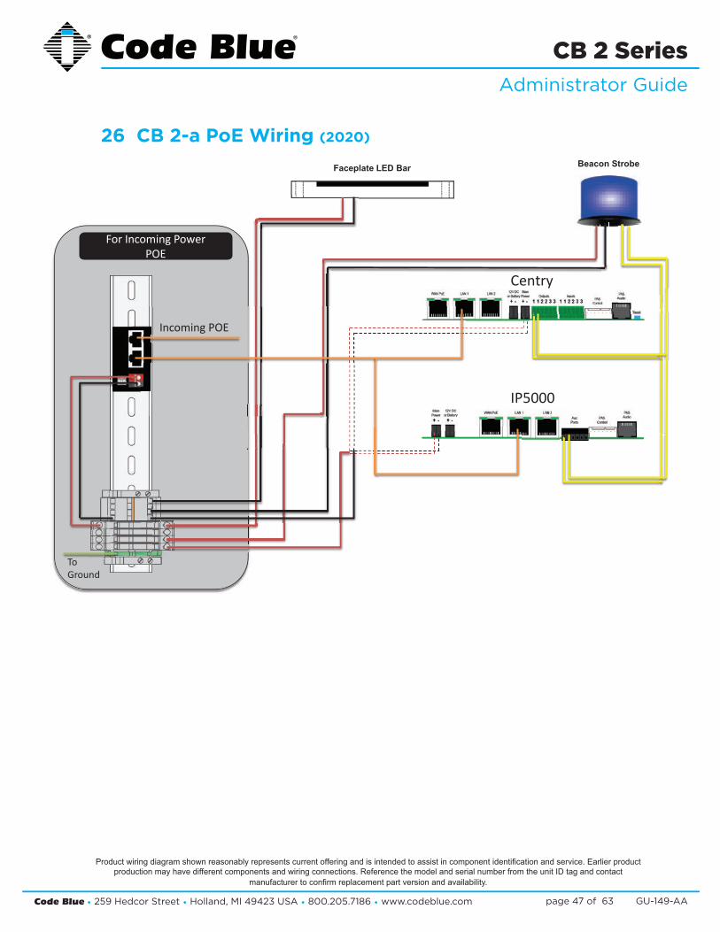
26 CB 2-a PoE Wiring (2020)
Product wiring diagram shown reasonably represents current offering and is intended to assist in component identifi cation and service. Earlier product production may have different components and wiring connections. Reference the model and serial number from the unit ID tag and contact
manufacturer to confi rm replacement part version and availability.

Code Blue • 259 Hedcor Street • Holland, MI 49423 USA • 800.205.7186 • www.codeblue.com GU-149-AApage 48 of 63
CB 2 SeriesAdministrator Guide
27 Legacy CB 2-a Wiring Diagram (prior to 2020)
Product wiring diagram shown reasonably represents current offering and is intended to assist in component identifi cation and service. Earlier product production may have different components and wiring connections. Reference the model and serial number from the unit ID tag and contact
manufacturer to confi rm replacement part version and availability.
FULL FILENAME
C:\USERS\MRUUD.CODEBLUE\APPDATA\LOCAL\MICROSOFT\WINDOWS\TEMPORARY INTERNET FILES\CONTENT.OUTLOOK\EHKAOED2\CB2A WIRINGDIAGRAM-B.VSD
SIZE FSCM NO DWG NO REV
DRAWN Mike Rose CB-2a Wiring Diagram B
ISSUED 7/22/16 SCALE 1 : 1 7/26/2016 SHEET 3 OF 3Revised date
in out GRD
FrontPanelDisconnect
High VoltagePowerOption
CustomerProvidedPowerOption(12 – 24 VoltsAC or DC @ 12 watts nominal)
PoEPowerOption
LAN 2LAN 1WANPoE PAS
ControlAux portsPAS
Audio+ -+ -
IP5000 VoIP
IA4100 AnalogPAS
Control
Aux Outputs1 2 3
N.O.N.C.
AuxInputs
PASAudio12VDC or
BatteryMain
Power
Ethernet
POTS line - PSTN
Data +PoEDATAData Cat5e
100 – 240Vac / 0.5A277Vac /0.2A
to12Vdc 3.3A
Class 2
Neutral
Load
S-180-1224-LED
FP-LED Bar
Fuse’s
Beacon Strobe 1 AmpFP LED Light 0.5 or 1AmpIP5000 1 AmpIA4100 1.5 Amp
in out GRD
PoE Cat5e Source
Cat5eNon PoE - Cat5e
PoE splitterpowered
12VDC orBattery
MainPower
AC to DC
PoE Power (DC)
Low Voltage12- 24V AC - DC

Code Blue • 259 Hedcor Street • Holland, MI 49423 USA • 800.205.7186 • www.codeblue.com GU-149-AApage 49 of 63
CB 2 SeriesAdministrator Guide
For Incoming Power24V AC/DC or 100-277V AC
Incoming High Voltage AC
IP5000
IA4100
Beacon StrobeFaceplate LED Bar
To Ground
To Ground
RJ45/RJ11
Incoming Data Line
For High Voltage leave connected.
For Low Voltage disconnect and apply incoming power.
Incoming Low Voltage
28 CB 2-e Standard Wiring (2020)
Product wiring diagram shown reasonably represents current offering and is intended to assist in component identifi cation and service. Earlier product production may have different components and wiring connections. Reference the model and serial number from the unit ID tag and contact
manufacturer to confi rm replacement part version and availability.

Code Blue • 259 Hedcor Street • Holland, MI 49423 USA • 800.205.7186 • www.codeblue.com GU-149-AApage 50 of 63
CB 2 SeriesAdministrator Guide
For Incoming PowerPOE
Centry
IP5000
Beacon StrobeFaceplate LED Bar
Incoming POE
To Ground
29 CB 2-e PoE Wiring (2020)
Product wiring diagram shown reasonably represents current offering and is intended to assist in component identifi cation and service. Earlier product production may have different components and wiring connections. Reference the model and serial number from the unit ID tag and contact
manufacturer to confi rm replacement part version and availability.

Code Blue • 259 Hedcor Street • Holland, MI 49423 USA • 800.205.7186 • www.codeblue.com GU-149-AApage 51 of 63
CB 2 SeriesAdministrator Guide
30 CB 2-e 120V Standard Wiring (2015-2020)
(with Triad Transformer)
Lighting Units
StrobeTrigger
LED Faceplate light12 – 24 Volts AC or DC
Power Supply
Fuse Block
in out GRD
Network SurgeProtector
in out GRD
POTS Line SurgeProtector
Network
Telco Line
1
InputsA
uxinput1
Aux
input2
Phone
line
Audio
Output
+- G +-
Output1 2 3
N.O.N.C.
PASControl
PASAudio
Battery 12V @ 2.0Ahr
12–
24V
oltsA
CorD
C
IA4100
LANLANLANPoE
PASControl
PASAudio
+ - + - Audio
Output
1
Optional Battery 12V @ 2.0Ahr
Ethernet
Aux
Output2
Aux
Input1
Aux Output 1
Aux ports
IP5000
12–
24V
oltsA
CorD
C
Beacon Strobe12 – 24 Volts AC or DC
· LED Area light 1.5 Amp· LED Faceplate Light 0.5 Amp· LED Beacon Strobe 0.5 AMP· IP5000 1.0 amp· IA4100 1.5 amp
Fuses
120V to 24V AC @ 40V A
120V AC
Product wiring diagram shown reasonably represents current offering and is intended to assist in component identifi cation and service. Earlier product production may have different components and wiring connections. Reference the model and serial number from the unit ID tag and contact
manufacturer to confi rm replacement part version and availability.

Code Blue • 259 Hedcor Street • Holland, MI 49423 USA • 800.205.7186 • www.codeblue.com GU-149-AApage 52 of 63
CB 2 SeriesAdministrator Guide
31 Legacy PoE Installation Instructions (prior to 2020)
2
802.3at Switch
LAN 2LAN 1WANPoE PAS
ControlAux portsPAS
Audio+ -+ -Power | Battery
S-550S1000
Ethernet
1
IP5000 Connector Side
43b
3
DATA – PoE+DATA
12 V DC
LED Faceplate Light Bar
2Second: Manifold fused red leadand black wires are secured tospring cage connector on the PoE+Splitter. SEE DIAGRAM
Third: Connect the DATA cable RJ-45from the Splitter “DATA” to theIP5000 WAN PoE port.
Voltage Selector Switch on the backmust be in the 12V DC position
3
4
Fourth: Plug in the Ethernet PoECat 5e Cable to Data+PoE Inputjack on the Splitters.Upon PoE Negotiation with thePoE switch port, power will begranted to the Splitter, and theindicator along with the deviceattached will turn on.
CAT5e< 3ft
in out GRD
3ftCat5e
CustomerCat5e
A-700
Electcial Modes 12VDC Amps WattageInRush (I) 2.00 24InRush Avg 0.40 4.8
Standby 0.55 6.6Talk - In Call 0.78 9.36
Grounding:
Should a ground be needed, there’sa ground screw on the enclosurewith grounding logo next to it.When the splitter is mounted to themounting bracket the bracketbecomes the ground to the chassisof the enclosure, however localcodes may require a ground wire beattached to the screw in order tocomply.
When connecting PoE to the unit’sinternal ground, make sure theunit itself is grounded to anoutside local ground.
3b
12V DC switch positionfavors the DATA – PoE+
side of the module
DC Power Out
DAT
AD
ATA
+Po
E+
PoE Ack
CBXXXX PoE Splitter
1.00
1.37
1First: Electrical connections, All 4Code Blue devices should to beconnected to the 5 place manifold

Code Blue • 259 Hedcor Street • Holland, MI 49423 USA • 800.205.7186 • www.codeblue.com GU-149-AApage 53 of 63
CB 2 SeriesAdministrator Guide
--
/
32 CB 2 Series 24V or 120V Multi-Tap Power Brick Wiring (prior to 2020)
Product wiring diagram shown reasonably represents current offering and is intended to assist in component identifi cation and service. Earlier product production may have different components and wiring connections. Reference the model and serial number from the unit ID tag and contact
manufacturer to confi rm replacement part version and availability.

Code Blue • 259 Hedcor Street • Holland, MI 49423 USA • 800.205.7186 • www.codeblue.com GU-149-AApage 54 of 63
CB 2 SeriesAdministrator Guide
33 CB 2 Series 120V Standard Wiring (prior to 03/2013) (with Hammond Transformer) (with Hammond Transformer)
Product wiring diagram shown reasonably represents current offering and is intended to assist in component identifi cation and service. Earlier product production may have different components and wiring connections. Reference the model and serial number from the unit ID tag and contact
manufacturer to confi rm replacement part version and availability.

Code Blue • 259 Hedcor Street • Holland, MI 49423 USA • 800.205.7186 • www.codeblue.com GU-149-AApage 55 of 63
CB 2 SeriesAdministrator Guide
34 Legacy CB 2-e with Public Address Wiring Diagram
POWER SUPPLY
CB 2-E with Public Address SPEAKER/AMP
IA4100 COMMUNICATION CONNECTIONS
RJ-11 cord
Fiber to FXS (ATA) ConverterFiber
11751
POTS line
Cat 5e or 6
LIGHTING
1111
+ - + -
1
+-
IA4100 SPEAKERPHONE IP5000 SPEAKERPHONEPAS
CONTROLPAS
AUDIO AUXPORTS
LAN PoE LAN 1 LAN 2 PASCONTROL
PASAUDIO
NOTE: Use the supplied modular inter-connects to link the unit’s various powered devices.
• Multi-Tap LV fuses are generally 2A GMA
AUDIO OUTPUT
120V, 240V, 277V, 347V AC @ 250V A
Aux In-put 2Aux
Input1
12V DC
24V AC
ChassisGround
12-24V AC or DC
OUTPUT
1 2 3N.O.N.C.
G-+ -+31 2
4
BATTACCPOWER
AUXINPUTS
12-24V AC or DC standard
BATTPWR
Aux Out-
put 1
Battery 12V @ 2.0Ahr
Aux Out-
put 2
Aux Input 1
Battery 12V @ 2.0Ahr
POWER MANIFOLD
MULTI-TAP
RJ-11 cord
Fiber to FXS (ATA) ConverterFiber
11751
FiberPOTS line
GRD
GRD
Common or Neg
PAS Audio
PAS Control
PAS Gen2 Amp24V AC @ 3 Amps
12-24V AC or DC standard
LEDFaceplateLight12-24V AC or DC
Beacon/Strobe12-24V AC or DC
PhoneLine
AudioOutput
phone specifi c
Product wiring diagram shown reasonably represents current offering and is intended to assist in component identifi cation and service. Earlier product production may have different components and wiring connections. Reference the model and serial number from the unit ID tag and contact
manufacturer to confi rm replacement part version and availability.
IP5000 COMMUNICATION CONNECTIONS
Copper Cat 6
Ethernet Surge Protector
One pair modularFiber
Converter

Code Blue • 259 Hedcor Street • Holland, MI 49423 USA • 800.205.7186 • www.codeblue.com GU-149-AApage 56 of 63
CB 2 SeriesAdministrator Guide
Product wiring diagram shown reasonably represents current offering and is intended to assist in component identification and service. Earlier product produc-tion may have different components and wiring connections. Reference the model and serial number from the unit ID tag and contact the manufacturer to confirm replacement part version and availability. The information contained herein is subject to change without notice.
12V
12V
35 Legacy CB 2-e with AED Housing Wiring Diagram

Code Blue • 259 Hedcor Street • Holland, MI 49423 USA • 800.205.7186 • www.codeblue.com GU-149-AApage 57 of 63
CB 2 SeriesAdministrator Guide
36 CB 2-s Wiring Diagram
POWER SUPPLY
CB 2-E with Public Address SPEAKER/AMP
IA4100 COMMUNICATION CONNECTIONS
RJ-11 cord
Fiber to FXS (ATA) ConverterFiber
11751
POTS line
Cat 5e or 6
LIGHTING
1111
+ - + -
1
+-
IA4100 SPEAKERPHONE IP5000 SPEAKERPHONEPAS
CONTROLPAS
AUDIO AUXPORTS
LAN PoE LAN 1 LAN 2 PASCONTROL
PASAUDIO
NOTE: Use the supplied modular inter-connects to link the unit’s various powered devices.
• Multi-Tap LV fuses are generally 2A GMA
AUDIO OUTPUT
120V, 240V, 277V, 347V AC @ 250V A
Aux In-put 2Aux
Input1
12V DC
24V AC
ChassisGround
12-24V AC or DC
OUTPUT
1 2 3N.O.N.C.
G-+ -+31 2
4
BATTACCPOWER
AUXINPUTS
12-24V AC or DC standard
BATTPWR
Aux Out-
put 1
Battery 12V @ 2.0Ahr
Aux Out-
put 2
Aux Input 1
Battery 12V @ 2.0Ahr
POWER MANIFOLD
MULTI-TAP
RJ-11 cord
Fiber to FXS (ATA) ConverterFiber
11751
FiberPOTS line
GRD
GRD
Common or Neg
PAS Audio
PAS Control
PAS Gen2 Amp24V AC @ 3 Amps
12-24V AC or DC standard
LEDFaceplateLight12-24V AC or DC
Beacon/Strobe12-24V AC or DC
PhoneLine
AudioOutput
phone specifi c
Product wiring diagram shown reasonably represents current offering and is intended to assist in component identifi cation and service. Earlier product production may have different components and wiring connections. Reference the model and serial number from the unit ID tag and contact
manufacturer to confi rm replacement part version and availability.
IP5000 COMMUNICATION CONNECTIONS
Copper Cat 6
Ethernet Surge Protector
One pair modularFiber
Converter

Code Blue • 259 Hedcor Street • Holland, MI 49423 USA • 800.205.7186 • www.codeblue.com GU-149-AApage 58 of 63
CB 2 SeriesAdministrator Guide
37 Multi-Tap Transformer Wiring
Primary Volt Amps 250
Secondar olt Amps 160
ETL – UL ______________
Low Voltage Outputs5 AmpsA C5 AmpsD C
24 VAC
24 VA 2V DCConverter
12VDC12VDC
12VDC2a mp fuse
24VAC2a mp fuse
Multi-Ta ransformer Primary
IncomingSupplier
Primary Side of theTransformer
SecondarTransformer
White
Yellow
Brown
Gray
Black
240
277
Hot
Joined
Source L1 (White)
Source
Source
White
Black
Yellow
Brown
Blue
Gray
120
Neutral
Capped
Capped
Source L1 (White)
Source L2 (Black)
Only connect one HO ir he voltagepoint matchin ou ource voltage.
T w e to tg y r s
p T
Side of they
y V
Power from
Hot L2
Hot L2
toC 1
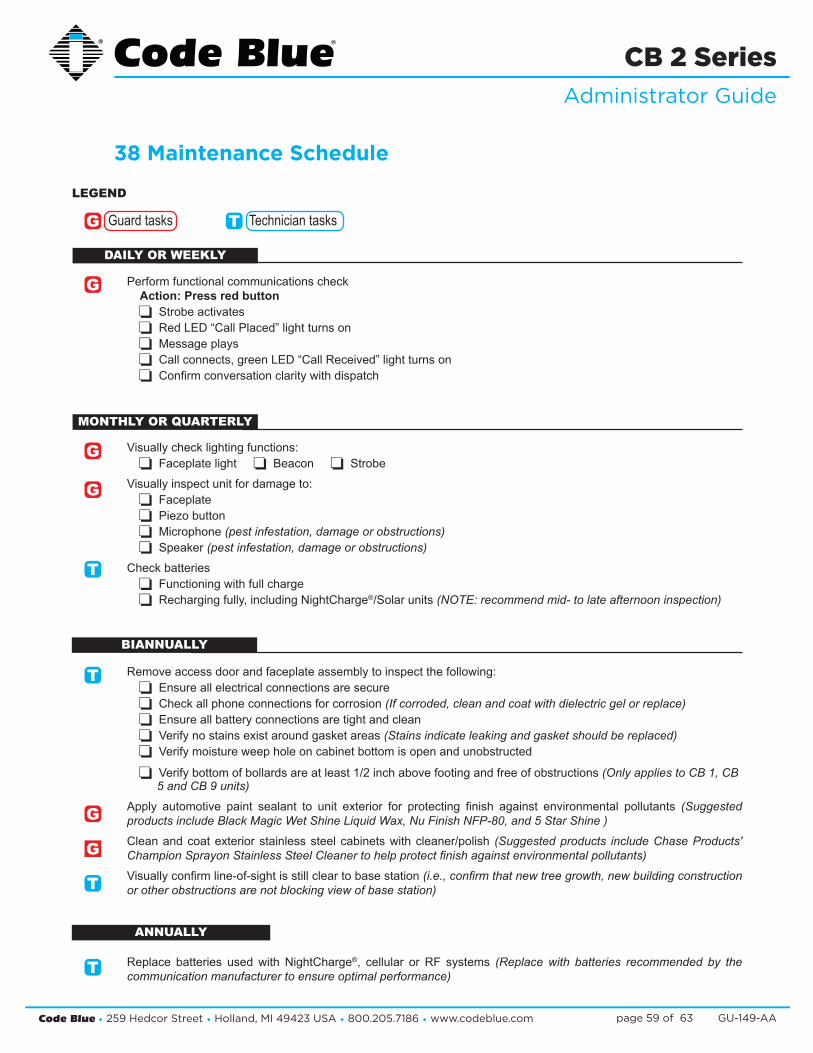
Code Blue • 259 Hedcor Street • Holland, MI 49423 USA • 800.205.7186 • www.codeblue.com GU-149-AApage 59 of 63
CB 2 SeriesAdministrator Guide
38 Maintenance Schedule
Perform functional communications check Action: Press red button
Strobe activates Red LED “Call Placed” light turns on Message plays Call connects, green LED “Call Received” light turns on Confirm conversation clarity with dispatch
Visually check lighting functions: Faceplate light Beacon Strobe
Visually inspect unit for damage to: Faceplate Piezo button Microphone (pest infestation, damage or obstructions) Speaker (pest infestation, damage or obstructions)
Check batteries Functioning with full charge Recharging fully, including NightCharge®/Solar units (NOTE: recommend mid- to late afternoon inspection)
Remove access door and faceplate assembly to inspect the following: Ensure all electrical connections are secure Check all phone connections for corrosion (If corroded, clean and coat with dielectric gel or replace) Ensure all battery connections are tight and clean Verify no stains exist around gasket areas (Stains indicate leaking and gasket should be replaced) Verify moisture weep hole on cabinet bottom is open and unobstructed
Verify bottom of bollards are at least 1/2 inch above footing and free of obstructions (Only applies to CB 1, CB 5 and CB 9 units)
Apply automotive paint sealant to unit exterior for protecting finish against environmental pollutants (Suggested products include Black Magic Wet Shine Liquid Wax, Nu Finish NFP-80, and 5 Star Shine )
Clean and coat exterior stainless steel cabinets with cleaner/polish (Suggested products include Chase Products' Champion Sprayon Stainless Steel Cleaner to help protect finish against environmental pollutants)
Visually confirm line-of-sight is still clear to base station (i.e., confirm that new tree growth, new building construction or other obstructions are not blocking view of base station)
Replace batteries used with NightCharge®, cellular or RF systems (Replace with batteries recommended by the communication manufacturer to ensure optimal performance)
Guard tasks Technician tasks
LEGEND
G
BIANNUALLY
MONTHLY OR QUARTERLY
DAILY OR WEEKLY
G T
G
G
G
T
T
G
T
T
ANNUALLY
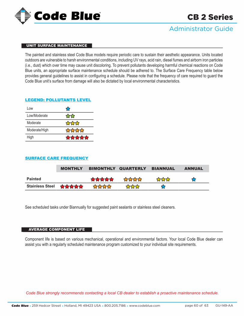
Code Blue • 259 Hedcor Street • Holland, MI 49423 USA • 800.205.7186 • www.codeblue.com GU-149-AApage 60 of 63
CB 2 SeriesAdministrator Guide
MONTHLY BIMONTHLY QUARTERLY BIANNUAL ANNUAL
Painted êêêêêêêêêê êêêêêêêê êêêêêê êêStainless Steel êêêêêêêêêê êêêêêêêê êêêêêê êê
The painted and stainless steel Code Blue models require periodic care to sustain their aesthetic appearance. Units located outdoors are vulnerable to harsh environmental conditions, including UV rays, acid rain, diesel fumes and airborn iron particles (i.e., dust) which over time may cause unit discoloring. To prevent pollutants developing harmful chemical reactions on Code Blue units, an appropriate surface maintenance schedule should be adhered to. The Surface Care Frequency table below provides general guidelines to assist in configuring a schedule. Please note that the frequency of care required to guard the Code Blue unit’s surface from damage will also be dictated by local environmental characteristics.
Low êêLow/Moderate êêêêModerate êêêêêêModerate/High êêêêêêêêHigh êêêêêêêêêê
LEGEND: POLLUTANTS LEVEL
See scheduled tasks under Biannually for suggested paint sealants or stainless steel cleaners.
Component life is based on various mechanical, operational and environmental factors. Your local Code Blue dealer can assist you with a regularly scheduled maintenance program customized to your individual site requirements.
UNIT SURFACE MAINTENANCE
AVERAGE COMPONENT LIFE
SURFACE CARE FREQUENCY
Code Blue strongly recommends contacting a local CB dealer to establish a proactive maintenance schedule.
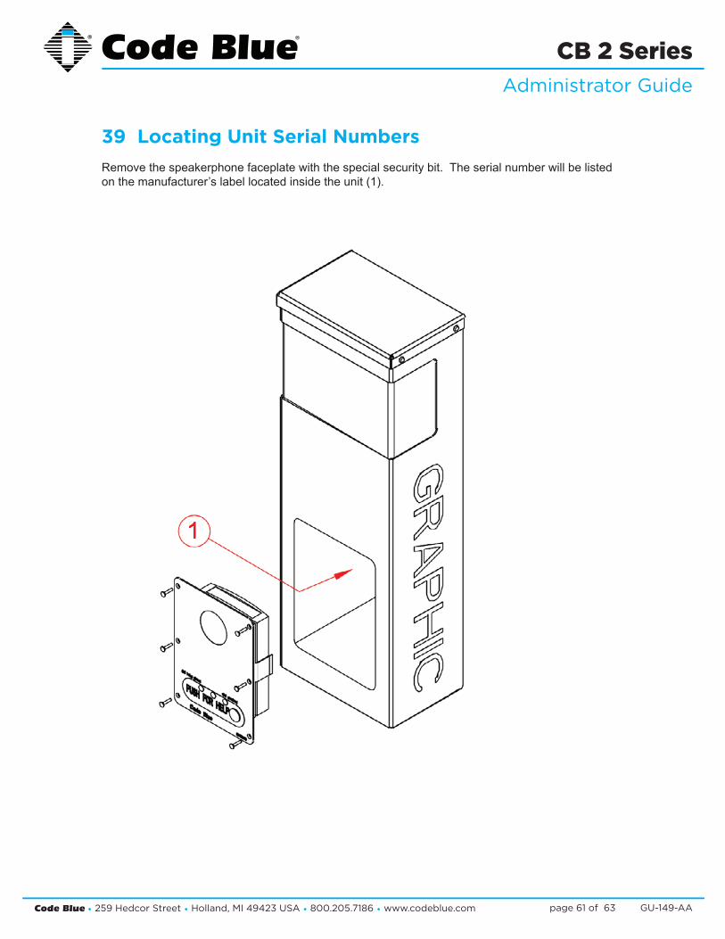
Code Blue • 259 Hedcor Street • Holland, MI 49423 USA • 800.205.7186 • www.codeblue.com GU-149-AApage 61 of 63
CB 2 SeriesAdministrator Guide
39 Locating Unit Serial Numbers Remove the speakerphone faceplate with the special security bit. The serial number will be listed on the manufacturer’s label located inside the unit (1).
1

Code Blue • 259 Hedcor Street • Holland, MI 49423 USA • 800.205.7186 • www.codeblue.com GU-149-AApage 62 of 63
CB 2 SeriesAdministrator Guide
40 Warranty
Code Blue Corporation provides a limited warranty on this product. Refer to your sales agreement to establish the terms. In addition, Code Blue’s standard warranty language, as well as information regarding support for this product while under warranty, is available at www.codeblue.com/support.
In Case of Breakdown
In case of system breakdown, discontinue use and contact :
Tech Support at [email protected] or call 800-205-7186, option 3.
In Case of Abnormal Operation
If the unit emits smoke or an unusual smell, if water or other foreign material enters the enclosure, or if you drop the unit or damage the enclosure, power off the unit immediately and contact:
Code Blue Customer Service at [email protected] or call Customer Service at 800-205-7186, option 2.

Code Blue • 259 Hedcor Street • Holland, MI 49423 USA • 800.205.7186 • www.codeblue.com GU-149-AApage 63 of 63
CB 2 SeriesAdministrator Guide
41 Download Information
Download Information
CSC-132-G
Code Blue now has a centralized location where you can find installation, setup, information, configuration and operation instructions. 1. Centry® Administrator Guide: www.codeblue.com/resources/guides 2. CB 1 Series Administrator Guide: www.codeblue.com/resources/guides 3. CB 2 Series Administrator Guide: www.codeblue.com/resources/guides 4. CB 4 Series Administrator Guide: www.codeblue.com/resources/guides 5. CB 5 Series Administrator Guide: www.codeblue.com/resources/guides 6. CB 9 Series Administrator Guide: www.codeblue.com/resources/guides 7. CB RT Administrator Guide: www.codeblue.com/resources/guides 8. Phone Enclosures Administrator Guide: www.codeblue.com/resources/guides 9. Stainless Steel Maintenance Guide: www.codeblue.com/support 10. IA4100 Administrator Guide: www.codeblue.com/resources/guides 11. IP5000 Administrator Guide: www.codeblue.com/resources/guides 12. IP1500/2500 Administrator Guide: www.codeblue.com/resources/guides 13. ToolVox® X3 Administrator Guide: www.codeblue.com/resources/guides 14. Public Address Administrator Guide: www.codeblue.com/resources/guides 15. Blue Alert® MNS User Guide: www.codeblue.com/resources/guides 16. Blue Alert® EMS User Guide: www.codeblue.com/resources/guides 17. IP1500/IP2500 Firmware: www.codeblue.com/support/firmware 18. IP5000 Versions 1.X & 2.X Firmware: www.codeblue.com/support/firmware
For Legacy Product Information: www.codeblue.com/legacy-products These guides should contain all the information needed for your application. If further information is required, please contact [email protected].