cbd01.07.0100c 2.4ghz cable dipole antenna draft
TRANSCRIPT

SPE-16-8-002/A/SS Page 1 of 19
SPECIFICATION
Part No. : CBD01.07.0100C
Product Name : 2.4GHz Cable Dipole Antenna
Feature : 2.4GHz Wi-Fi/ISM band Antenna
Lightweight (1.47g) and Thin for UAV Applications
Flexible for easy integration
High Efficiency >70%
3dBi Peak Gain
Omnidirectional
Linear Polarization
100mm Ø1.37 Micro-Coaxial Cable
with IPEX MHF1 (U.FL) Connector
Cable and Connector Customizable
RoHS Compliant

SPE-16-8-002/A/SS Page 2 of 19
1. Introduction
The CBD01 2.4GHz antenna is a micro coax cable dipole antenna with omnidirectional
radiation pattern which has a high efficiency of over 70% at 2.4GHz. These attributes
make it ideal for use on 2.4GHz UAV applications for FPV (First-Person View) and
contribute to a more reliable link. The CBD01 antenna comes in a small form factor
which is very lightweight and easy to attach. The standard product comes with 100mm
low loss 1.37mm coaxial cable and IPEX MHFI (U.FL) connector.
The cable routes conveniently directly out of the bottom of the antenna, reducing the
volume the antenna takes up in the device to an absolute minimum compared to other
designs. The cable dipole antenna is the ideal antenna solution for fitting into narrow
spaces and still maintaining high performance.
Due to the potential for detuning or nearby interference in a device environment,
Taoglas recommends that you contact us at our regional sales office for integration
support, testing, and optimization of the antenna in your device before going to
production. Customized cable and connector versions available, subject to minimum
order quantities.
SPE-16-8-002/A/SS Page 3 of 19
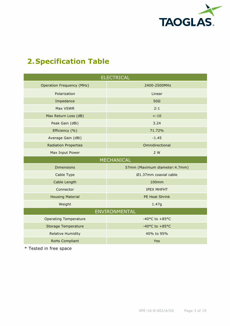
2. Specification Table
ELECTRICAL Operation Frequency (MHz) 2400-2500MHz
Polarization Linear
Impedance 50Ω
Max VSWR 2:1
Max Return Loss (dB) <-10
Peak Gain (dBi) 3.24
Efficiency (%) 71.72%
Average Gain (dBi) -1.45
Radiation Properties Omnidirectional
Max Input Power 2 W
MECHANICAL Dimensions 57mm (Maximum diameter:4.7mm)
Cable Type Ø1.37mm coaxial cable
Cable Length 100mm
Connector IPEX MHFHT
Housing Material PE Heat Shrink
Weight 1.47g
ENVIRONMENTAL Operating Temperature -40°C to +85°C
Storage Temperature -40°C to +85°C
Relative Humidity 40% to 95%
RoHs Compliant Yes
* Tested in free space

SPE-16-8-002/A/SS Page 4 of 19
3. Antenna Characteristics
3.1. Return Loss (Free Space)
3.2. Efficiency (Free Space)

SPE-16-8-002/A/SS Page 5 of 19
3.3. Peak Gain (Free Space)
3.4. Average Gain (Free Space)
SPE-16-8-002/A/SS Page 6 of 19
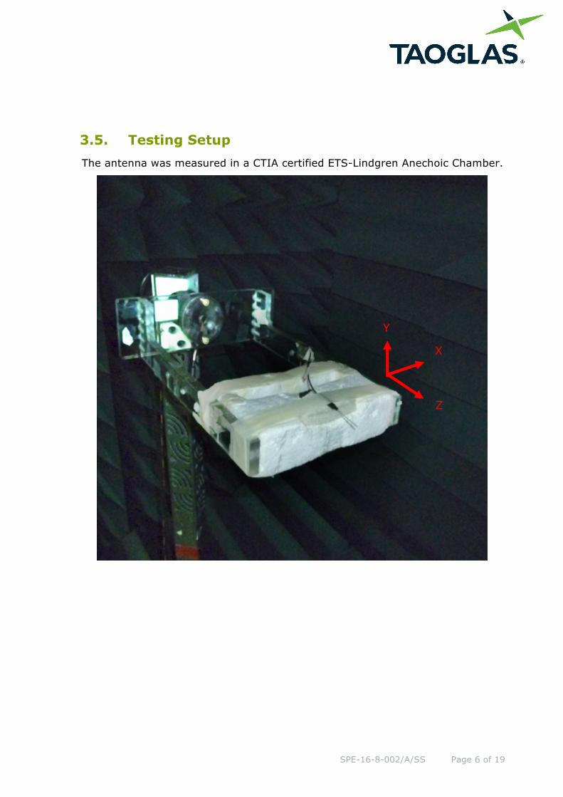
3.5. Testing Setup The antenna was measured in a CTIA certified ETS-Lindgren Anechoic Chamber.
X
Z
Y
SPE-16-8-002/A/SS Page 7 of 19
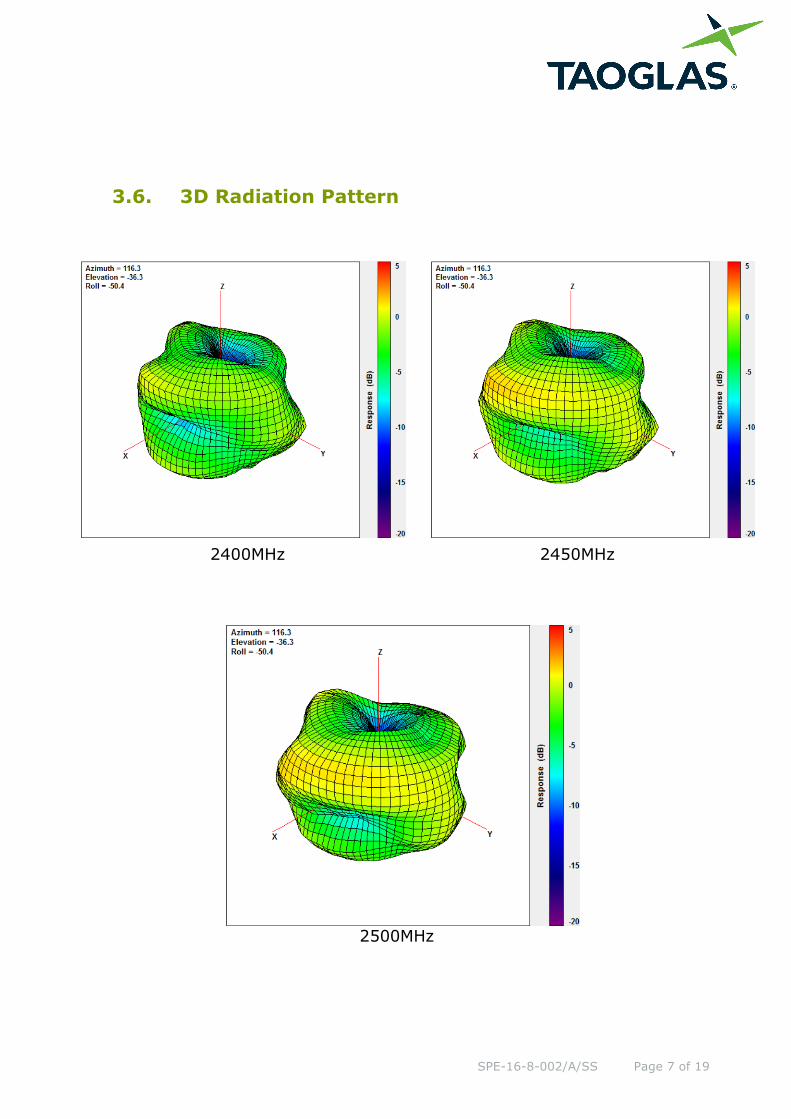
3.6. 3D Radiation Pattern
2500MHz
2400MHz 2450MHz

SPE-16-8-002/A/SS Page 8 of 19
3.7. 2D Radiation Pattern
XY Plane
XZ Plane
X
Y
X
Z

SPE-16-8-002/A/SS Page 9 of 19
YZ Plane
Z
Y

SPE-16-8-002/A/SS Page 10 of 19
4. Drawing (Unit: mm)

SPE-16-8-002/A/SS Page 11 of 19
5. Packaging

SPE-16-8-002/A/SS Page 12 of 19
6. Installation
2.4GHz remote control receivers usually need two separate 2.4GHz receiver antennas
for receive diversity.
* 2.4GHz remote control receivers + 2.4GHz receiver antennas
The user connects the two CBD.01 antennas to a 2.4GHz remote control receiver. The
two antennas should be placed at 90 degrees to each other. They should be kept as
straight as possible but also kept away from each other as much as possible. If not,
effective range could be reduced.
Our antennas should be placed at both sides of the 2.4G remote receiver. Then the
best RF signal condition can be obtained at any flying attitude. The antennas must be
kept 15mm away from metal materials.

SPE-16-8-002/A/SS Page 13 of 19
Cable ties or adhesive can be used on the bottom of the filter jacket for the most
reliable mounting solution. Ideally, the antenna is mounted close to the outer edge of
the UAV device to allow it to radiate outwards and receive signals without obstruction
from internal components in the device.
In order to have best maximum antenna efficiency, it is suggested that the antenna is
installed on plastic or fiberglass surfaces. Also it is important to keep the antennas
away from the motor, ESC, and other electrical noise sources to reduce interference
entering the receiver.
SPE-16-8-002/A/SS Page 14 of 19
7. Application Note
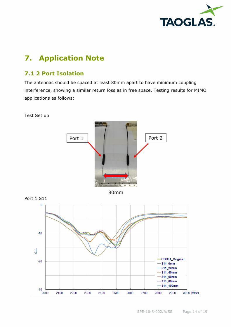
7.1 2 Port Isolation The antennas should be spaced at least 80mm apart to have minimum coupling
interference, showing a similar return loss as in free space. Testing results for MIMO
applications as follows:
Test Set up
80mm Port 1 S11
Port 1 Port 2

SPE-16-8-002/A/SS Page 15 of 19
Port 2 S11
Two Ports Isolation

SPE-16-8-002/A/SS Page 16 of 19
7.2 Ground Approximate Effects
The Antenna needs to be at least 54mm away from a comparatively large metal surface to have similar return loss as in free space. In order to maintain good antenna performance, we suggest that a suitable distance to large metal planes are reserved. If the distance is smaller than 54mm, Taoglas can offer the fine tuning service to prepare custom antennas, subject to minimum order quantities.
Test set up
54mm from Metal (Ground)

SPE-16-8-002/A/SS Page 17 of 19
7.3 Bending Angle on Antenna Main Body
Due to the dipole antenna structure, cable routing of the antenna itself does not have much effect on performance. In real life scenarios however, the antenna matching and efficiency may be changed through bending the main body. The test setup and results below show the antennas response to bending.
Test Set up
@45°
SPE-16-8-002/A/SS Page 18 of 19
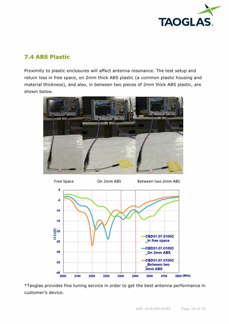
7.4 ABS Plastic
Proximity to plastic enclosures will affect antenna resonance. The test setup and return loss in free space, on 2mm thick ABS plastic (a common plastic housing and material thickness), and also, in between two pieces of 2mm thick ABS plastic, are shown below.
*Taoglas provides fine tuning service in order to get the best antenna performance incustomer’s device.

SPE-16-8-002/A/SS Page 19 of 19
Taoglas makes no warranties based on the accuracy or completeness of the contents of this
document and reserves the right to make changes to specifications and product descriptions at
any time without notice. Taoglas reserves all rights to this document and the information
contained herein.
Reproduction, use or disclosure to third parties without express permission is strictly
prohibited.
Copyright © Taoglas Ltd.
Mouser Electronics
Authorized Distributor
Click to View Pricing, Inventory, Delivery & Lifecycle Information: Taoglas:
CBD01.07.0100C