cbtc 2 - irse cbtc... · communication rev 05 ... cbtc 2.0 the model assumes vc2 is a moving object...
TRANSCRIPT

CBTC 2.0Vehicle Centric Architecture & Train to Train
Communication Rev 05
Naeem Ali Director & Principal Consultant
www.CBTCSolutions.ca

CBTC 2.0 ARCHITECTUREDeparture from Tradition

CBTC 1.0 - Architecture
• Classic CBTC 1.0 Architecture
• First generation of CBTC technology
ZC 1 ZCN
Ethernet Network TCP/IP
Radio Netw
ork TCP/IP SW PD
Discrete IO
IOC1
SW PD
IOCN
VC1 VC2
Ethernet Network TCP/IP
ZC FunctionsTrain TrackingSafe Train SeparationMovement AuthorityPSD ControlInterlocking
VC FunctionsPropulsionBrakingATOTrain DoorsPassenger Info sys
ATS
NMS PIS/PAS
Master
ClockWS1 WS2
Ethernet Network TCP/IP
Central Control
CC FunctionsRoutingSchedulePassenger Info Sys

CBTC 2.0 - Architecture
• Zone Controller is removed
ZC 1 ZCN
Ethernet Network TCP/IP
Radio Netw
ork TCP/IP SW PD
Discrete IO
IOC1
SW PD
IOCN
VC1 VC2
Ethernet Network TCP/IP
ZC FunctionsTrain TrackingSafe Train SeparationMovement AuthorityPSD ControlInterlocking
VC FunctionsPropulsionBrakingATOTrain DoorsPassenger Info sys
ATS
NMS PIS/PAS
Master
ClockWS1 WS2
Ethernet Network TCP/IP
Central Control
CC FunctionsRoutingSchedulePassenger Info Sys

CBTC 2.0 - Architecture
• ZC functions are shifted to the VC & IOC
• Vehicles communicate with each other (VC to VC communication).
• VC and ATS communicate directly with the IOC
• Vital System Database maintains system info
VC1 VC2
ATS
ZC 1 ZCN
Ethernet Network TCP/IP
Radio Netw
ork TCP/IP
SW PD
NMS PIS/PAS
Master
ClockWS1 WS2
Ethernet Network TCP/IP
Central Control
Discrete IO
IOC1
SW PD
IOCN
VC1 VC2
Ethernet Network TCP/IP
ZC FunctionsTrain TrackingSafe Train SeparationMovement AuthorityPSD ControlInterlocking
VC FunctionsPropulsionBrakingATOTrain DoorsPassenger Info sys
CC FunctionsRoutingSchedulePassenger Info Sys
VC FunctionsTrain TrackingSafe Train SeparationMovement Authority
VSDb
Vital System Database
PSD ControlInterlocking

CBTC 2.0 - Architecture
• Focus of this presentation will be• ZC functions transferred
to the VC• ZC functions transferred
to the IOC • VSDb
VC1 VC2
ATS
Ethernet Network TCP/IP
Radio Netw
ork TCP/IP
SW PD
NMS PIS/PAS
Master
ClockWS1 WS2
Ethernet Network TCP/IP
Central Control
Discrete IO
IOC1
SW PD
IOCN
VC1 VC2VC FunctionsPropulsionBrakingATOTrain DoorsPassenger Info sys
CC FunctionsRoutingSchedulePassenger Info Sys
VC FunctionsTrain TrackingSafe Train SeparationMovement Authority
VSDb
Vital System Database
PSD ControlInterlocking

TRAIN TRACKINGIf a train cannot be tracked, it cannot be protected
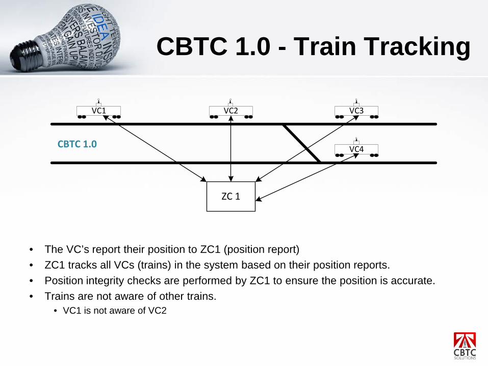
CBTC 1.0 - Train Tracking
• The VC’s report their position to ZC1 (position report)• ZC1 tracks all VCs (trains) in the system based on their position reports.• Position integrity checks are performed by ZC1 to ensure the position is accurate.• Trains are not aware of other trains.
• VC1 is not aware of VC2
ZC 1
VC3VC2VC1
VC4CBTC 1.0

CBTC 1.0 - Train Tracking
• If there is a failure, such as a communication failure, ZC1 will create a buffer around the train.
• ZC1 will prevent other trains from entering this area.

CBTC 2.0 - Train Tracking
• VC2 communicates with the VC in front and behind creating an awareness of all trains in the vicinity.
• VC2 will perform position integrity checks on the position reports received from the other VC’s
VC3VC2VC1
VC4CBTC 2.0
VSDb

CBTC 2.0 - Train Tracking
• VC2 communicate with the VC in front and behind creating an awareness of all trains in the vicinity.
• VC2 will perform position integrity checks on the position reports received from the other VC’s
• If there is a failure, such as a communication failure, VC2 will create a buffer around the train.
• VC2 will report the failure and the buffer boundary to the VSDb.• VSDb will update all VC’s in the system of the failed train and buffer boundary.
INTERLOCKING

CBTC 1.0 – Interlocking
• The ATS requests a route for VC1 that requires the switch to be in the normal position.

CBTC 1.0 – Interlocking
• The ATS requests a route for VC1 that requires the switch to be in the normal position.• If the switch can be reserved for VC1, ZC1 will command the switch to move to the
normal position, lock and reserve the switch.

CBTC 1.0 – Interlocking
• When the train passes through the switch, ZC1 will release (unlock) the switch.

CBTC 2.0 – Interlocking
• The IOC is a input/output controller configured for a switch.• When controlling a switch, the IOC will:
• Command the switch to normal or reverse.• Lock the switch• Read status• Send statuses to the ATS and to any VC communicating with the IOC.• Receive switch commands from the VC and ATS.

CBTC 2.0 – Interlocking
• The ATS will send a route to VC1 that goes through the switch.• When VC1 is within range of the IOC, VC1 will:
• Establish a communication link with the IOC • Command the IOC to move the switch to normal and lock the switch.
• The IOC will command the switch to move normal, lock and & reserve the switch and send the switch position to VC1.
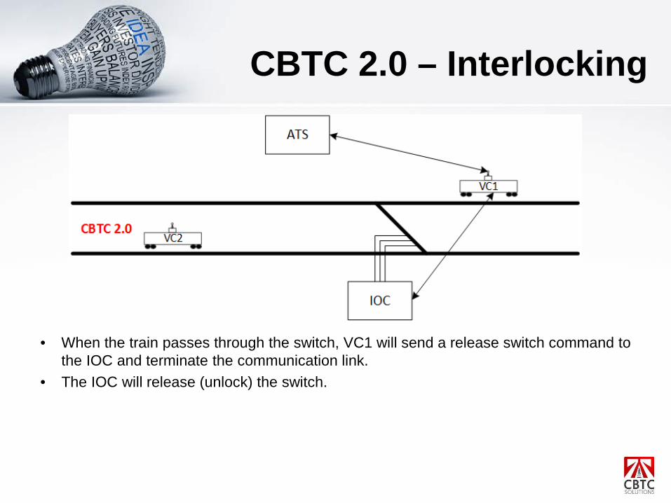
CBTC 2.0 – Interlocking
• When the train passes through the switch, VC1 will send a release switch command to the IOC and terminate the communication link.
• The IOC will release (unlock) the switch.

SAFE TRAIN SEPARATION & MOVEMENT AUTHORITYHow close to bring the trains

CBTC 1.0 – Safe Train Separation
• ZC1 is aware of the status of all elements along the track such as switch status, location of trains and any other obstacle.
• Based on this information, ZC1 calculates the Movement Authority (MA) up to the first obstacle in the path of the train.
• ZC1 transmits the MA to VC2.

CBTC 1.0 – Safe Train Separation
• Based on the MA, VC2 will determine the stopping point.• VC2 will stop the train at the stopping point.
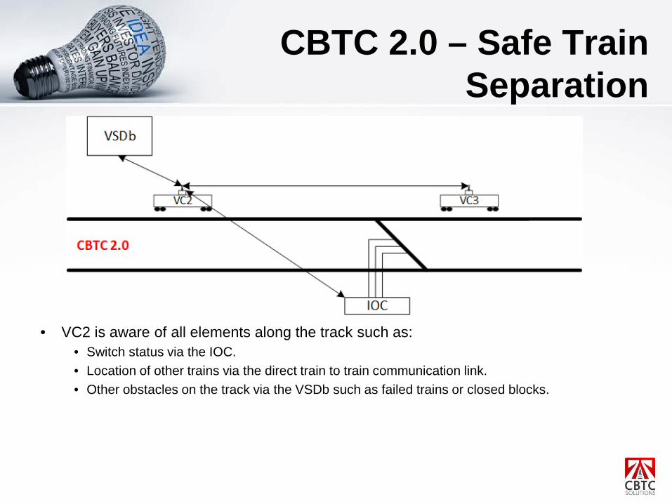
CBTC 2.0 – Safe Train Separation
• VC2 is aware of all elements along the track such as:• Switch status via the IOC.• Location of other trains via the direct train to train communication link.• Other obstacles on the track via the VSDb such as failed trains or closed blocks.

CBTC 2.0 – Safe Train Separation
• VC2 is aware of all elements along the track such as:• Switch status via the IOC.• Location of other trains via the direct train to train communication link.• Other obstacles on the track via the VSDb such as failed trains or closed blocks.
• Based on this information, VC2 will calculate the MA to the nearest obstacle.

CBTC 2.0 – Safe Train Separation
• Based on the MA, VC2 will determine stopping point.• VC2 will stop the train at the stopping point.

SCENARIO Put it all Together

CBTC 2.0 – Scenario

CBTC 2.0 – Scenario
• VC1 will establish a communication link with the ATS and VSDb

CBTC 2.0 – Scenario
• VC1 will establish a communication link with the ATS and VSDb• The ATS will provide VC1 with a destination.• VC1 will calculate the MA and stopping point to the nearest obstacle.

CBTC 2.0 – Scenario
• When VC1 is within range, VC1 will establish a communication link with the IOC controlling the switch and send a command to move the switch to the normal position.
• The IOC will command the switch to move normal, lock and reserve the switch.

CBTC 2.0 – Scenario
• Once the switch is in the normal position, VC1 will determine the next obstacle (VC2).• VC1 will establish a communication link with VC2 and receive speed and direction of
travel information.• The MA and stopping point will move past the switch to VC2.

CBTC 2.0 – Scenario
• As VC2 moves forward, VC1 will move the MA and stopping point forward. • When VC1 passes the switch, VC1 will send a release switch command to the IOC and
terminate the communication link.• The IOC will release the switch.

ADVANTAGES OF CBTC 2.0Vehicle Centric Architecture and the new way.

Advantages of CBTC 2.0• Improved Safe Braking Model• Shorter Headways• Reduced response times• Reduced equipment• Increased reliability and maintainability

CBTC 1.0 - Safe Braking Model
• This safe braking model is based on IEEE 1474.1-2004 Annex D• The safe braking model assumes VC2 is stationary and the safety distance is based on
this assumption.• If VC1 emergency brakes, it would stop just short of the brick wall.• The safety distance is unnecessarily long because VC2 is moving away from the brick
wall while VC1 is emergency braking the train.
VC1 VC2
80kph 80kph
Brick Wall
CBTC 1.0
The model assumes VC2 is an immoveable object, even
though it’s moving
Safety Distance
Emergency Brake Curve

CBTC 2.0 - Safe Braking Model
• Since the trains communicate with each other, VC1 is aware of the speed of VC2 and travel direction.
• Therefore, VC1’s safety distance can overlap into VC2.• If VC1 were to emergency brake, by the time it reached VC2, VC2 will have moved
away.
VC1 VC2
80kph 80kph
CBTC 2.0
The model assumes VC2 is a moving object
Safety Distance
Emergency Brake Curve
for VC1

CBTC 2.0 - Safe Braking Model
• Since the trains communicate with each other, VC1 is aware of the speed of VC2 and travel direction.
• Therefore, VC1’s safety distance can overlap into VC2.• If VC1 were to emergency brake, by the time it reached VC2, VC2 will have moved
away. • Allows trains to travel closer together and keep the safety distance as short as possible.
VC1 VC2
80kph
CBTC 2.0
The model assumes VC2 is a moving object
Safety Distance
Emergency Brake Curve
for VC1 Train emergency braked to a stop

CBTC 2.0 – Shorter Headways
• Headway is affected by various factors such as the turn back design and dwell times but the safety distance is also a factor. The above diagram is an over simplification to illustrate a point.
• A benefit of the reduced safety distance is the headway between trains is also reduced.• More trains can move through the system.
VC1 VC2
80kph 80kph
CBTC 1.0 Safety Distance
Headway
VC1 VC2
80kph 80kph
CBTC 2.0 Safety Distance
Headway

CBTC 2.0 – Faster Response Time
CBTC 2.0 Loss of Switch Correspondence
Delay = A + B + C + D msec
ATS
Ethernet Network TCP/IP
Radio Netw
ork TCP/IP
SW PD
NMS PIS/PAS
Master
ClockWS1 WS2
Ethernet Network TCP/IP
Central Control
Discrete IO
IOC1
SW PD
IOCN
SW PD
IOC2
VC1 VC2
AB
CD
ATS
ZC 1 ZC 2 ZCN
Ethernet Network TCP/IP
Radio Netw
ork TCP/IP SW PD
NMS PIS/PAS
Master
ClockWS1 WS2
Ethernet Network TCP/IP
Central Control
Discrete IO
IOC1
SW PD
IOCN
SW PD
IOC2
VC1 VC2
Ethernet Network TCP/IP
AB
CD
E
F
Delay = A + B + C + D +E + F msec
CBTC 1.0 Loss of Switch Correspondence

CBTC 2.0 – Faster Response Time
Delay = A msec
CBTC 2.0 Train Timeout
ATS
Ethernet Network TCP/IPRadio N
etwork TCP/IP
SW PD
NMS PIS/PAS
Master
ClockWS1 WS2
Ethernet Network TCP/IP
Central Control
IOC1
VC1 VC2
AVC1 VC2
ATS
ZC 1
Ethernet Network TCP/IP
Radio Netw
ork TCP/IP
SW PD
NMS PIS/PAS
Master
ClockWS1 WS2
Ethernet Network TCP/IP
Central Control
IOC1
VC1 VC2
A
VC1 VC2
B
C
Delay = A + B + C msec
CBTC 1.0 Train Timeout

CBTC 2.0 – Less Equipment• Reduced Equipment
• The hardware for the ZC is no longer required
• Increased Reliability and Maintainability• Less equipment to fail• Less equipment to maintain

CBTC 2.0 – Disadvantage• Radio Network
• The latency on the wireless network is greater due to the number of links the VC has to establish.
• Major impediment to implementation.

CONCLUSION

Conclusion
• CBTC 2.0 is a radical departure from the first generation CBTC architecture.
• CBTC 2.0 offers: • Improved headway by reducing safety distances.• Improved safety by reducing response times.• Increased reliability and reduced maintenance due to
less equipment.• Disadvantage is the wireless network latencies.

Contact Info
• If your organization is looking for CBTC expertise, reach out to me via email.
• Email• [email protected]
• CBTC blog:• http://bit.ly/cbtcsolutions-blog• http://www.cbtcsolutions.ca/blog