cca-3074 channel console appliance planning guide · 2015-08-11 · cca-3074 will be communicating...
TRANSCRIPT
CCA-3074 Channel Console Appliance Planning Guide P/N 707159-003


CCA-3074 Planning
707159-003 iii
Revision Information
Issue/Revision Schedule
Comments Revision Number Date Initial Release 707159-001 04/01/2012 Second Release 707159-002 06/27/2013 Third Release 707159-003 07/02/2015

iv 707159-003
CCA-3074 Planning
707159-003 v
Table of Contents
Revision Information ......................................................................................................... iii Table of Contents.................................................................................................................v Chapter 1. CCA-3074 Overview...................................................................................... 1-1 Product Overview ....................................................................................................... 1-1 Optional CSS32 Coax Subsystem............................................................................... 1-2 CCA-3074 Environmental Parameters ....................................................................... 1-3 CSS32 Environmental Parameters.............................................................................. 1-3 CCA-3074 Power Requirements................................................................................. 1-4 CSS32 Power Requirements ....................................................................................... 1-4 Ethernet Requirements................................................................................................ 1-4 ESCON Cabling Requirements................................................................................... 1-5 FICON Cabling Requirements.................................................................................... 1-5 CCA-3074 Directly Attached Management Console Interface (Optional)................. 1-5 CSS32 Management Options...................................................................................... 1-6 Platform Management Using the Visara eManager Product ...................................... 1-6 Field Upgradeability ................................................................................................... 1-6 Chapter 2. Planning for Your Install................................................................................ 2-1 Identifying the Non-SNA Environment...................................................................... 2-1 Worksheet Discussion................................................................................................. 2-2 Number of Mainframes.......................................................................................... 2-2 Number of LPARs ................................................................................................. 2-2 EMIF Support on the Mainframe........................................................................... 2-2 Operating Systems in Use...................................................................................... 2-2 Coax Terminal Requirements ................................................................................ 2-3 StorageTek LMUs.................................................................................................. 2-3 IBM 3290............................................................................................................... 2-3 Redundant Console Controllers ............................................................................. 2-3 Number of Consoles Required for Each LPAR..................................................... 2-4 Need/Desire to Use One Console for Multiple LPARs ......................................... 2-4 Need to Display Multiple LPARs at Once on a Display ....................................... 2-4 Remote Access Requirement ................................................................................. 2-4 Hot Console Session Requirement......................................................................... 2-4 Session Sharing Requirement ................................................................................ 2-4 Long Wave or Short Wave FICON ....................................................................... 2-5 Replacing Existing ESCON 3174 Controllers............................................................ 2-6 Replacing Bus and TAG Controllers .......................................................................... 2-6 Determining the Need for ESCON Directors ............................................................. 2-6 When to Use EMIF ..................................................................................................... 2-6 Coax Requirement Planning ....................................................................................... 2-7 StorageTek LMUs Planning ....................................................................................... 2-7 FICON Usage.............................................................................................................. 2-7
vi 707159-003
IBM 3290 Plasma Display Planning........................................................................... 2-7 Planning for the Visara 500LX................................................................................... 2-8 Planning for Hot Console Sessions............................................................................. 2-8 Use of ESCON Channel Extenders............................................................................. 2-8 Secure Network Connections...................................................................................... 2-9 LAN Printers Supported as Consoles ......................................................................... 2-9 Management Planning ................................................................................................ 2-9 Planning for eManager Support ................................................................................ 2-10 CCA-3074 Maximum Capability Chart.................................................................... 2-11 Determining the Number of CCA-3074s.................................................................. 2-12 Parameter Definition Cross Reference Chart............................................................ 2-14 Chapter 3. Host Gens – OS/390 with HCD ..................................................................... 3-1 Task List...................................................................................................................... 3-1 HCD Panel 1 – Define, Modify, or View Configuration Data ................................... 3-1 HCD Panel 2 – Operating System Configuration List................................................ 3-2 HCD Panel 3 – Switch List......................................................................................... 3-2 HCD Panel 4 – Change Switch Definition ................................................................. 3-3 HCD Panel 5 – Port List ............................................................................................. 3-3 HCD Panel 6 – Change Port Definition...................................................................... 3-4 HCD Panel 7 – Switch Configuration List ................................................................. 3-4 HCD Panel 8 – Port Matrix......................................................................................... 3-5 HCD Panel 9 – View Connected Units....................................................................... 3-5 HCD Panel 10 – Processor List .................................................................................. 3-6 HCD Panel 11 – Actions on Selected Processors ....................................................... 3-6 HCD Panel 12 – Partition List .................................................................................... 3-7 HCD Panel 13 – View Partition / Channel Paths........................................................ 3-7 HCD Panel 14 – View Partition / Control Units......................................................... 3-8 HCD Panel 15 – View Partition / Devices.................................................................. 3-8 HCD Panel 16 – Control Unit List.............................................................................. 3-9 HCD Panel 17 – Control Unit List.............................................................................. 3-9 HCD Panel 18 – Change Control Unit Definition .................................................... 3-10 HCD Panel 19 – View Control Unit Definition........................................................ 3-10 HCD Panel 20 – Select Processor / Control Unit ..................................................... 3-11 HCD Panel 21 – Add Device .................................................................................... 3-11 HCD Panel 22 – Device / Processor Definition........................................................ 3-12 HCD Panel 23 – Define Device / Processor ............................................................. 3-12 HCD Panel 23 (2) – HCD Help ................................................................................ 3-13 HCD Panel 24 – Define Device Candidate List........................................................ 3-13 HCD Panel 25 – Define Device to Operating System Configuration....................... 3-14 HCD Panel 26 – Define Device Parameters / Features............................................. 3-14 HCD Panel 27 – Define Device to Operating System Configuration....................... 3-14 HCD Panel 28 – I/O Device List .............................................................................. 3-15 HCD Panel 29 – Define Device / Processor ............................................................. 3-15
CCA-3074 Planning
707159-003 vii
Chapter 4. IOCDS Sample Definitions............................................................................ 4-1 Example 1 – Typical 3174 Replacement (ESCON) ................................................... 4-2 Example 2 – Typical 3174 Replacement (FICON)..................................................... 4-4 Example 3 – Device Candidate List not Used ............................................................ 4-5 Example 4 – EMIF and ESCON Directors Used........................................................ 4-6 Example 5 – Multiple LCSS and ESCON .................................................................. 4-8 Example 6 – Multiple LCSS and FICON ................................................................. 4-10 Chapter 5. CSS32 External Coax Subsystem .................................................................. 5-1 What is the External Coax Subsystem........................................................................ 5-1 CSS32 Factory Default Configuration........................................................................ 5-1 Chapter 6. Frequently Asked Questions .......................................................................... 6-1 Appendix A. Consoles Planning Worksheet................................................................... A-1

CCA-3074 Planning
707159-003 1-1
Chapter 1. CCA-3074 Overview
Product Overview The CCA-3074 is a versatile 3U, rack-mountable enterprise class server product capable of running many features and functions traditionally supported by a variety of legacy products. The Non-SNA feature set that comes standard with the CCA-3074 provides functionality traditionally found on the IBM 2074 Control Unit product family, as well as the Visara SCON family. Up to 16 LPARs are supported through each ESCON and FICON interface. Up to two ESCON and four FICON interfaces are supported providing a maximum of 96 LPAR support. Several hundred user sessions can be supported including both console sessions and VTAM sessions. With the optional CSS32 to provide coax cable connectivity, the CCA-3074 can also easily accommodate the functionality provided by traditional IBM 3174 and 3274 console controllers as well as most plug compatible products such as the Visara SCON-20L, SCON-22L, SCON-25L, and 1174-25S products, the Memorex Telex 1174-10L, 1174-20L, 1174-15X, and 1374-1L, and the McData 7100 products. Configuration of the CCA-3074 is achieved by means of a secure web browser interface (HTTPS). This browser connection can be made through the network or from a direct attached monitor, keyboard, and mouse. The CCA-3074 ships with a default configuration including a default IP address. To connect from an external PC you must either modify the default configuration for your own network requirements (requires modifying the FEP4600.ini file on a 3.5” floppy disk) or modify the IP configuration of the PC you are using to configure with (assign a compatible IP address). Once configured, the CCA-3074 is capable of running independently, without human intervention. That is, if power is lost and regained, it will automatically boot back into service using the stored configuration. (You may need to reactivate any console sessions.) You can manage the platform using the same secure web browser connection from anywhere that you can connect to the platform via IP. Multiple management console interfaces are supported by the CCA-3074, making it ideal for remote disaster recovery operations.
Chapter 1. Installation
1-2 707159-003
Optional CSS32 Coax Subsystem The optional CSS32 Coax Subsystem can be added to the CCA-3074 to provide up to 32 real coax ports for attachment of 3270 displays, printers, and Storagetek coax LMU connections. The CSS32 comes in a separate rack mountable platform which can be mounted in the same physical rack as the CCA-3074 and interconnected by a single crossover Ethernet cable. Multiple CSS32 platforms can be supported by a single CCA-3074. In instances where multiple CSS32 platforms are to be supported, it may be necessary to use a small Ethernet hub or switch to interconnect the multiple platforms. It is also possible to directly attach multiple CSS32 platforms by adding a Quad Ethernet interface card into the CCA-3074. The CSS32 may similarly be attached to multiple CCA-3074 platforms. Because communication between CSS32 and CCA-3074 uses standard Ethernet IP connections it is possible for a CCA-3074 to communicate to a CSS32 platform over an IP network. The CSS32 does not natively support SSL encryption, so external SSL encryption or VPN is recommended to provide security when direct crossover connections are not used. The CSS32 comes standard preconfigured to communicate with one CCA-3074. In the factory default configuration, 31 coax ports are defined to support displays or LMU connections and 1 coax port is defined to support a printer. The factory configuration can be modified to support other combinations of devices and destination platforms.
CCA-3074 Planning
707159-003 1-3
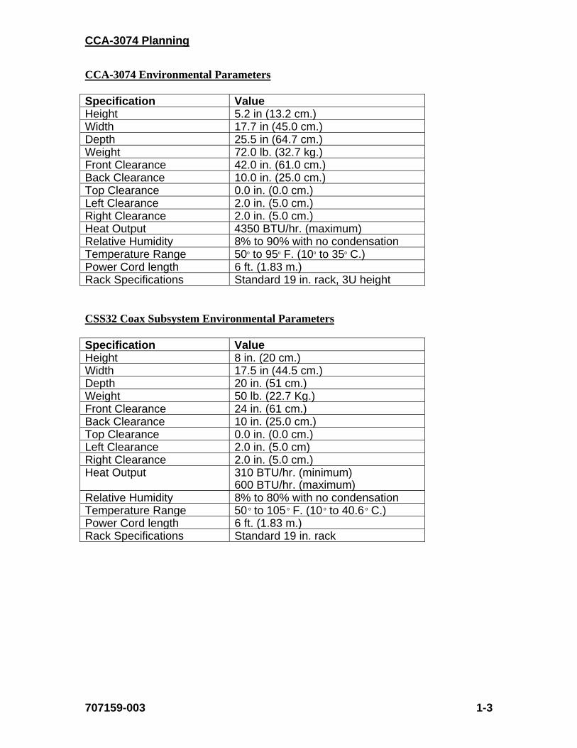
CCA-3074 Environmental Parameters Specification Value Height 5.2 in (13.2 cm.) Width 17.7 in (45.0 cm.) Depth 25.5 in (64.7 cm.) Weight 72.0 lb. (32.7 kg.) Front Clearance 42.0 in. (61.0 cm.) Back Clearance 10.0 in. (25.0 cm.) Top Clearance 0.0 in. (0.0 cm.) Left Clearance 2.0 in. (5.0 cm.) Right Clearance 2.0 in. (5.0 cm.) Heat Output 4350 BTU/hr. (maximum) Relative Humidity 8% to 90% with no condensation Temperature Range 50o to 95o F. (10o to 35o C.) Power Cord length 6 ft. (1.83 m.) Rack Specifications Standard 19 in. rack, 3U height CSS32 Coax Subsystem Environmental Parameters Specification Value Height 8 in. (20 cm.) Width 17.5 in (44.5 cm.) Depth 20 in. (51 cm.) Weight 50 lb. (22.7 Kg.) Front Clearance 24 in. (61 cm.) Back Clearance 10 in. (25.0 cm.) Top Clearance 0.0 in. (0.0 cm.) Left Clearance 2.0 in. (5.0 cm) Right Clearance 2.0 in. (5.0 cm.) Heat Output 310 BTU/hr. (minimum)
600 BTU/hr. (maximum) Relative Humidity 8% to 80% with no condensation Temperature Range 50 o to 105 o F. (10 o to 40.6 o C.) Power Cord length 6 ft. (1.83 m.) Rack Specifications Standard 19 in. rack
Chapter 1. Installation
1-4 707159-003
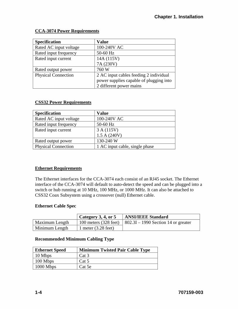
CCA-3074 Power Requirements Specification Value Rated AC input voltage 100-240V AC Rated input frequency 50-60 Hz Rated input current 14A (115V)
7A (230V) Rated output power 760 W Physical Connection 2 AC input cables feeding 2 individual
power supplies capable of plugging into 2 different power mains
CSS32 Power Requirements Specification Value Rated AC input voltage 100-240V AC Rated input frequency 50-60 Hz Rated input current 3 A (115V)
1.5 A (240V) Rated output power 130-240 W Physical Connection 1 AC input cable, single phase Ethernet Requirements The Ethernet interfaces for the CCA-3074 each consist of an RJ45 socket. The Ethernet interface of the CCA-3074 will default to auto-detect the speed and can be plugged into a switch or hub running at 10 MHz, 100 MHz, or 1000 MHz. It can also be attached to CSS32 Coax Subsystem using a crossover (null) Ethernet cable. Ethernet Cable Spec Category 3, 4, or 5 ANSI/IEEE Standard Maximum Length 100 meters (328 feet) 802.3I – 1990 Section 14 or greater Minimum Length 1 meter (3.28 feet) Recommended Minimum Cabling Type Ethernet Speed Minimum Twisted Pair Cable Type 10 Mbps Cat 3 100 Mbps Cat 5 1000 Mbps Cat 5e

CCA-3074 Planning
707159-003 1-5
ESCON Cabling Requirements The ESCON interface card used by the CCA-3074 uses the larger Duplex ESCON interface cable. Most newer mainframes such as the z-processors use the smaller MTRJ connector. Both Duplex/Duplex ESCON and Duplex/MTRJ ESCON cables can be obtained from Visara or sourced locally. FICON Cabling Requirements The FICON card used by the CCA-3074 comes in three versions; single port, dual port, and quad port. Each interface uses the popular LC type connector. Each FICON interface can be ordered to support either Long Wave FICON Transceivers or Short Wave FICON Transceivers. Selection of Long Wave or Short Wave is dependent on what the CCA-3074 will be communicating with on the other end of the FICON cable. Note that FICON cables also come in Long Wave (single-mode) or Short Wave (multi-mode) versions. The FICON interface supported by the CCA-3074 is capable of running at 2.125 Gbps, 4.25 Gbps, and 8 Gbps speeds. Maximum cable lengths are dependent upon the transceiver type used and the speed of the interface according to the following table.
Fiber Optic Cable Maximum Length Minimum Length Connector OM3 – Multimode 50/125 micron fiber (2000 MHz*km bandwidth cable)
2.125 Gbps: 0.5-500m 4.25 Gbps: 0.5-380m 8.5 Gbps: 0.5-150m
.5 meters LC
OM2 – Multimode 50/125 micron fiber (500 MHz*km bandwidth cable)
2.125 Gbps: 0.5-300m 4.25 Gbps: 0.5-150m 8.5 Gbps: 0.5-50m
.5 meters LC
OM1 – Multimode 62.5/125 micron fiber (200 MHz*km bandwidth cable)
2.125 Gbps: 0.5-150m 4.25 Gbps: 0.5-70m 8.5 Gbps: 0.5-21m
.5 meters LC
OS1/OS2 – Single-mode 9 micrometer fiber with LC connectors
2.125 Gbps: 0.5-10 km 4.25 Gbps: 0.5-10 km 8.5 Gbps: 0.5-10 km
.5 meters LC
CCA-3074 Directly Attached Management Console Interface (Optional) Component Specification Monitor SVGA (minimum resolution 1024 x 768) Keyboard PS2 interface, 104 Key Mouse PS2 interface
Chapter 1. Installation
1-6 707159-003
CSS32 Management Options The CSS23 can be configured and managed using any coax attached CUT display device, or through the Ethernet interface from the CCA-3074 Directly Attached Management Console (described above) using one of the integrated Telnet client sessions. If the CSS32 is attached to the CCA-3074 through a switch or hub, it is also possible to configure and manage the CSS32 from a remote Telnet device. The CSS32 comes preconfigured from the factory, ready to attach to a single CCA-3074 through a crossover (null) Ethernet cable. Platform Management Using the Visara eManager Product Both the CCA-3074 and CSS32 products may be managed remotely via the eManager software product from any Windows PC that has eManager installed upon it. Field Upgradeability The CCA-3074 can be upgraded in the field for most features. Among the features that can be field upgraded are:
Additional ESCON interface (maximum of two are supported) Additional FICON interface (a single FICON card is supported with 1, 2 or 4
interfaces) Addition of Quad Ethernet card (maximum of 2 Quad Ethernet cards supported) Additional CU images (LPARs) beyond the default numbers to a maximum of 16
per ESCON/FICON interface
CCA-3074 Planning
707159-003 2-1
Chapter 2. Planning for Your Install
Identifying the Non-SNA Environment
First, take a moment to fill out the following worksheet to determine what your environment is, or what you wish to create. Several topic paragraphs are provided to help determine what is needed to satisfy your requirements. Finally, a worksheet at the back of this book may be used to map out your configuration prior to actually attempting to configure the CCA-3074. You may want to create a spreadsheet with a similar layout or make several copies of the worksheet to encompass your entire configuration requirement.
Number of mainframes? Number: _______
Number of LPARs? Number: _______
EMIF supported on any of the mainframes? (Yes/No) _______
ESCON/FICON Directors being used? (Yes/No) _______
Operating Systems in use? (OS/390, MVS/ESA, VM/ESA, VSE/ESA) _______
Coax Terminal Requirement ________
StorageTek LMUs (Yes/No) _______
IBM 3290 (Yes/No) _______
Redundant Console Controllers (Yes/No) _______
Number of consoles needed for each LPAR Number: _______
Need/desire to use one console for multiple LPARs (Yes/No) _______
Need to display multiple LPARs at once on a display (Yes/No) _______
Remote Access requirement? (Yes/No) _______
Hot Console session requirement (Yes/No) _______
Shared session requirement (Yes/No) ________
For FICON installs, are Long Wave or Short Wave interfaces required ________

Chapter 2. Planning for Your Installation
2-2 707159-003
Worksheet Discussion
Number of Mainframes: If more than one mainframe must be supported by the CCA-3074 then it is best to connect through ESCON/FICON Directors. If no ESCON/FICON Directors are available the CCA-3074 must have at least one cable connection to each mainframe. A maximum of two mainframes can be supported through ESCON when Directors are not used. A maximum of four mainframes can be supported through FICON when Directors are not used. If the mainframe that the CCA-3074 is attached to supports multiple logical channel subsystems (LCSS) then there is a requirement to attach to each LCSS via a separate cable when the connection is ESCON. Again if there are ESCON directors available, it is possible for the CCA-3074 to communicate with LPARs in each LCSS through the same interface. The FICON interface can span multiple LCSS.
Number of LPARs: There is at least one CNTLUNIT definition associated with each LPAR that will be defined for use with the CCA-3074. Each CNTLUNIT definition corresponds to one of the CU definitions on the CCA-3074. A maximum of 16 CUs are supported through each ESCON and FICON interface (maximum of 96 per platform).
EMIF Support on the Mainframe?: EMIF (ESCON Multiple Imaging Facility) or MIF (Multiple Imaging Facility) is the mainframe mechanism that allows multiple LPARs to share a single CHPID interface. If EMIF/MIF is not used then a Director is necessary to allow multiple LPARs to be supported over a single ESCON/FICON interface into the CCA-3074.
Operating Systems in Use?: Although the CCA-3074 supports all major IBM mainframe operating systems, it is still useful information when planning the use of the CCA-3074. If other than IBM operating systems are in use (such as a Fujitsu operating system) it is best to contact a Visara representative to determine whether the CCA-3074 is a solution.
CCA-3074 Planning
707159-003 2-3
Coax Terminal Requirement: The CCA-3074 does not support an onboard coax interface but uses an optional external Coax Subsystem (the CSS32). The external Coax Subsystem connects to the CCA-3074 using IP communications through an Ethernet interface. The external Coax Subsystem can be located nearby and use a simple Ethernet crossover cable, or can be connected remotely through an IP network. The direct attachment through an Ethernet crossover cable is the preferred method, for two reasons. 1) The CSS32 does not support SSL encryption natively, making attachment to a network more of a security issue than a direct attachment would be. 2) By not attaching to your network, the CSS32 should provide reliable connectivity even when you have network problems.
StorageTek LMUs: STK LMUs require a coax interface to communicate with the CCA-3074 through the external CSS32 Coax Subsystem described above. The CCA-3074 does not communicate to the STK LMU through an Ethernet (IP) connection.
IBM 3290: The IBM 3290 plasma display is DFT/DSL coax display commonly used in computer rooms for displaying up to four console sessions simultaneously. DSL terminals require that the controller they are attached to be capable of downloading a code set into them. The CSS32 coax subsystem may not support a 3290 properly. It is possible to replace the 3290 product with another Visara product (the 500LX product that is capable of supporting up to 10 sessions. With the 500LX it is possible to configure it for four sessions and display all four sessions on a flat panel display in much the same manner as a 3290. Note that the 500LX supports 4 color and 7 color displays as compared to the orange plasma monochrome of the 3290. It is also possible to configure the 3290 to display only orange characters if it is really desired.
Redundant Console Controllers: Most mainframe console environments require redundant consoles attached through redundant controller platforms to provide DR capabilities. This means duplication of the minimum platform requirement. Note that if your coax requirements are minimal, it is possible to drive a single CSS32 Coax Subsystem from two (or more) CCA-3074s.

Chapter 2. Planning for Your Installation
2-4 707159-003
Number of Consoles Required for Each LPAR: Normally there is a minimum requirement to have at least two consoles defined to each LPAR, to provide redundancy. Sometimes the number is actually higher to support additional console users or to subdivide the messages. With the Session Sharing feature of the CCA-3074 you may also be able to define fewer consoles than you would otherwise need, by allowing multiple users to share a single console session.
Need/Desire to Use One Console for Multiple LPARs: It might be needed to provide console support for multiple LPARs on one desktop. The CCA-3074 can be configured to allow multiple TN3270 sessions to be connected from a single TN3270 client. The ability to support multiple sessions on the client is a function of the client software. The CSS32 Coax Subsystem is capable of allowing up to 10 sessions to be managed from a single coax port, including attachment to multiple CCA-3074s.
Need to Display Multiple LPARs at Once on a Display: This is a function of the client. Visara offers TN3270 clients that may be used to display up to 4 complete sessions on the screen at once, and up to 10 total. Refer to the Visara 500LX thin client display.
Remote Access Requirement: By default, the TN3270 protocol is capable of allowing remote access to the unit since communication between the CCA-3074 and its clients is through an IP connection. Additionally, the CCA-3074 supports SSL encryption between itself and the TN3270 clients allowing safe secure connections even through the Internet.
Hot Console Session Requirement: Sometimes it is beneficial to have hot sessions configured on the CCA-3074. For hot sessions, once a console has been activated, it always appears to be powered on and active even if the client is no longer connected. This allows a client to connect to a console session without requiring someone to manually activate the console. This feature works well for lights out DR sites.
Session Sharing Requirement: Sometimes it is useful to allow multiple users to share the same console session. Multiple users can share a session on the CCA-3074 if configured for session sharing. This feature may aid in diagnostic and training functions. It may also allow you to get around the 99 console limitation of MVS environments.
CCA-3074 Planning
707159-003 2-5
Long Wave or Short Wave FICON: The FICON interface comes with the choice of connecting to either a single-mode optic cable supporting Long Wave signals or to multimode optic cable that requires Short Wave signals. The difference is in the form of a transceiver that plugs into the FICON interface card. Transceivers used on both ends of the cable must be compatible to the cable and each other. The card used by the CCA-3074 comes with the transceivers factory installed in it so it is important to order the proper card variation to plug into your equipment. Refer to the FICON Cabling Requirements section in the previous chapter for additional information.
Chapter 2. Planning for Your Installation
2-6 707159-003
Replacing Existing ESCON 3174 Controllers
Each of your existing 3174 Non-SNA controllers is capable of communicating to only one LPAR, and appearing as only one control unit image (CUI). Each 3174 is therefore utilizing only one CUADD of the 16 CUADD values that can be defined (0-F) through a single ESCON or FICON interface. It is common to use the same CUADD number for each 3174 (if no CUADD parameter is found in the CNTLUNIT macro of the gen, CUADD=0 is implied). The CCA-3074 provides support for multiple CUIs, allowing it to replace multiple 3174 controllers. To replace multiple 3174s with a single CCA-3074, even if they have ESCON interfaces, you will normally have to make some minor gen changes to direct the connection to the CCA-3074.
Replacing Bus and Tag Controllers
Bus and Tag definitions, ESCON, or FICON definitions are different, so you will always require Gen changes when replacing Bus and Tag controllers with a CCA-3074. A CCA-3074 with a single ESCON or FICON interface can replace up to 16 Bus and Tag controllers, or up to 32 controllers with two ESCON /FICON interfaces. Additional ESCON/FICON interfaces can support up to 96 total controllers.
Determining the Need for Directors
If you have more than two mainframe platforms or have multiple LPARs on a single mainframe that does not support EMIF/MIF, or if you are running multiple logical channel subsystems (LCSS) on a single mainframe, you will probably be best served by using ESCON and FICON directors. Directors allow multiple LPARs and multiple mainframes to communicate to a CCA-3074 through a single interface (up to 16 CU images). If Directors are to be used, consider implementing a redundant Director to eliminate a single point of failure.
When to Use EMIF/MIF
If your mainframe supports EMIF (Enterprise Multiple Imaging Facility) or MIF (Multiple Imaging Facility) and you are running multiple LPARs, making use of EMIF/MIF can greatly reduce the number of interfaces by allowing multiple LPARs (up to 15) to share a single channel.

CCA-3074 Planning
707159-003 2-7
Coax Requirement Planning
The CCA-3074 does not support direct coax attachment. Coax attachment can be provided using an external CSS32 Coax Subsystem. These appliances can be directly attached to the CCA-3074 using a crossover Ethernet cable, or may be positioned elsewhere on your IP network, even at a remote location. Each CSS32 Coax Subsystem can support up to 32 coax ports. One CCA-3074 can communicate with multiple CSS32 appliances and one CSS32 can communicate with multiple CCA-3074 platforms. It is also possible to obtain a CSS32 that can support up to 128 coax devices. If you need to support more than 32 coax devices contact a Visara representative to determine your options.
StorageTek LMUs Planning
StorageTek LMUs have a requirement to use a single coax connection for each LPAR that you wish to connect the LMU to. Be sure to allow for that in your calculation for the number of coax connections needed. The CCA-3074 does not support coax directly, but makes use of the external CSS32 to provide the coax connectivity. The CCA-3074 does not support Ethernet connections to a StorageTek LMU.
FICON Usage
The CCA-3074 supports a single FICON card. The card comes in 3 interface variations (single interface, dual interface, and quad interface). The interfaces on each card also have the option of using Long Wave or Short Wave transceivers and must be ordered to work in your environment. FICON support can be ordered as an upgrade to ESCON existing units and allows for the coexistence of ESCON and FICON connectivity.
IBM 3290 Plasma Display Planning
The 3290 plasma display can support up to 4 sessions through a single coax connection, but it is limited to communication to only one LPAR. Coax connectivity is handled through an external CSS32 Coax Subsystem available from Visara. An alternative to the use of the 3290 would be to use the Visara 500LX thin client product. The 500LX can support up to 10 sessions (in color), including simultaneous full screen display of 4 sessions to different LPARs.
Chapter 2. Planning for Your Installation
2-8 707159-003
Planning for the Visara 500LX
The Visara 500LX product is designed to support console sessions in a rather unique way. You can use it to display multiple console sessions on the screen (up to 4 full screen console sessions) through its TN3270E feature when using a monitor capable of supporting 1280 x 1024 resolution. Unlike other TN3270E clients however, you can optionally attach the 500LX directly through a coax connection (fewer security issues). The 500LX also supports an Ethernet connection. When connected through the coax connection, up to 10 sessions are supported through the CSS32 but the sessions are viewed one at a time.
Planning for Hot Console Sessions
One of the unique features available for the CCA-3074 allows Console sessions to remain powered on with the host LPAR, even when the client associated with the session is not currently connected. This is referred to as a Hot Console Session. Applications for the Hot Console Session include:
• Provide console connections for a lights out site.
• Provide a means for multiple operators, located in multiple locations to have access to the same console session at different times.
• Provide a tool for disaster recovery from a remote location.
Hot console sessions do not roll over to an alternate console unless the CCA-3074 is powered down, varied offline, or is no longer functional.
Use of Channel Extenders
There is nothing unique about the CCA-3074 that should cause problems using channel extenders. However, Visara has conducted no special testing with specific channel extenders to verify their correct operation. It is the customer’s responsibility to determine compatibility with another vendor’s channel extender, when used with the CCA-3074. Because the CCA-3074 supports clients remotely through TN3270 sessions, it might be better (and less expensive) to locate the CCA-3074 at the data center site and connect remotely from a TN3270 client.

CCA-3074 Planning
707159-003 2-9
Secure Network Connections
Secure network connections for TN3270 clients using Secure Socket Layer (SSL) protocol, is provided by the CCA-3074 as a configuration option. The CCA-3074 server is designed to provide secure SSL encrypted communication to PC desktops or any other TN3270 client platform that supports SSL. For PC emulators that do not support SSL encryption natively, Visara has software available (eConduit) that may be loaded onto the PC to provide the SSL encryption.
LAN Printers Supported as Consoles
LAN printers can be supported by the CCA-3074 through a couple of different mechanisms. TN3287 sessions can be set up internally on the CCA-3074 with output directed to a LAN printer or remote Unix/Linux server using LPD/LPR protocol. Visara thin clients can be used to provide the same function but staged remotely.
Management Planning
The CCA-3074 offers several options for management. Configuration changes can be made while the CCA-3074 is performing its normal duties. Most changes can be put into affect without requiring a restart. Host related changes on the CCA-3074 will normally require that the CHPID related to the host change is offline. To allow for routine maintenance and system changes, it is strongly suggested that more than one CCA-3074 be used to provide redundant console connections.
Configuration and management of the CCA-3074 is supported through a secure browser (https) connection. This browser connection can be initiated from a direct attached monitor, keyboard, and mouse, or from most any remote platform capable of running a web browser.
A unique management product produced by Visara for the purpose of managing the CCA-3074, as well as any external Coax Subsystems and Visara Thin Client/Console desktops is available. This product is called eManager. eManager communicates to the CCA-3074 using SSL encryption. eManager provides additional tools for management and diagnosing problems.

Chapter 2. Planning for Your Installation
2-10 707159-003
Planning for eManager Support
eManager is a platform management software product available from Visara for the purpose of managing most Visara products including the CCA-3074, CSS32 Coax Appliances, and 500LX Thin Client desktop product lines.
eManager can be used to communicate with CCA-3074 on site or off site through corporate networks or across the Internet. If you are to manage the CCA-3074 from a remote location over public connections, you might want to consider the use of a VPN or use SSL encryption.
Among the capabilities of eManager are:
• Provide CCA-3074 Software Configuration Backups (dynamic or scheduled)
• Provide management of multiple configurations on a single CCA-3074
• Provide Inventory Information Including a Report Generator (supports coax terminal Vital Product Data reporting)
• Provide Network Status of the CCA-3074, CSS32 Coax Appliance, and 500LX Visara Thin Clients through the Pulse Network Monitor feature of eManager
• Software and Configuration Management
• Remote Viewing of Event Logs including search and filter utilities and Other Diagnostic Information
• Telnet and Browser Interface into Remote CCA-3074
• Code and Configuration Management of CSS32 Coax Appliances used with the CCA-3074
• Code and Configuration Management of 500LX Visara Thin Client Products Used With the CCA-3074
• The Event Log manager provides a means to filter and search Event Logs pulled from CCA-3074s.
• The Debug Log manager allows you to pull Debug Logs from your CCA-3074s as well as delete old logs no longer needed.
• The System Dump manager allows you to initiate and retrieve System Dumps from your CCA-3074 platforms and delete those no longer needed.
CCA-3074 Planning
707159-003 2-11
CCA-3074 Maximum Capability Chart
Feature Value Notes
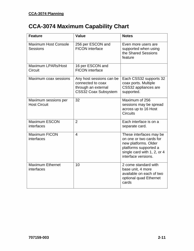
Maximum Host Console Sessions
256 per ESCON and FICON interface
Even more users are supported when using the Shared Sessions feature
Maximum LPARs/Host Circuit
16 per ESCON and FICON interface
Maximum coax sessions Any host sessions can be connected to coax through an external CSS32 Coax Subsystem
Each CSS32 supports 32 coax ports. Multiple CSS32 appliances are supported.
Maximum sessions per Host Circuit
32 Maximum of 256 sessions may be spread across up to 16 Host Circuits
Maximum ESCON interfaces
2 Each interface is on a separate card.
Maximum FICON interfaces
4 These interfaces may be on one or two cards for new platforms. Older platforms supported a single card with 1, 2, or 4 interface versions.
Maximum Ethernet interfaces
10 2 come standard with base unit, 4 more available on each of two optional quad Ethernet cards
Chapter 2. Planning for Your Installation
2-12 707159-003
Determining the Number of CCA-3074s
Use the CCA-3074 Maximum Capability Chart on the previous pages to help in determining the number of CCA-3074 and external Coax Subsystems that will be required to satisfy your requirements.
The minimum number of CCA-3074 platforms that are required is determined by several factors:
• Whether redundant Console Controllers will be used (recommended)
• The number of ESCON and FICON cables required to connect to the LPARs defined
• Whether redundant ESCON or FICON Directors are being used
• The number of LPARs defined
• The total number of consoles required
A minimum of two consoles, each located on separate CCA-3074s should be used for every critical application. This allows for a CCA-3074 to be powered down for routine maintenance or configuration changes. At least two CCA-3074s should be connected to each LPAR, to provide these connections.
When Directors are used, the overall number of CCA-3074s that would be required may be greatly reduced. Up to 16 LPARs (host circuits) can be connected through each ESCON and FICON interface.
When redundant Directors are available, two ESCON or FICON interfaces may be desired. The total number of LPAR connections (host circuits) that a CCA-3074 with two ESCON and four FICON interfaces can be configured for is 96.

CCA-3074 Planning
707159-003 2-13
Take time to fill out the Console Configurations Planning Worksheet found in Appendix A, or better yet a similar spreadsheet. This can be used to help determine the total number of consoles needed to satisfy your requirements. It can later be used as a reference to aid in performing the configuration of the CCA-3074. In determining the console requirement, remember the following:
The maximum number of sessions per LPAR supported by the CCA-3074 is 32. The maximum number of sessions per ESCON interface supported is 256.

Chapter 2. Planning for Your Installation
2-14 707159-003
Parameter Definition Cross Reference Chart
The following chart and notes can be used to help show the corresponding configuration parameters between the IOCDS definitions, HCD definitions, and the CCA-3074 configuration.
IOCDS HCD CCA-3074 MACRO Parameter Panel Parameter Panel Parameter
CNTLUNIT CUADD Change Control Unit Definition
Logical Address Update ESCON/FICON
CUs
CUADD
IODEVICE CNTLUNIT
UNITADD Define Device/Processor
Unit Address Update ESCON/FICON
CUs
Low Address
IODEVICE ADDRESS Add Device Number of Devices Update ESCON/FICON
CUs
High Address
CHPID Update CHPID Access and
Candidate List
Access List = Yes
IODEVICE
PARTITION
Define Device Candidate List
Partition/Reachable
Update ESCON/FICON
CUs
LPAR Number
CHPID SWITCH Add Channel Path
Dynamic Switch ID or Entry Switch
ID
N/A N/A
CNTLUNIT LINK Change Control Unit Definition
Link Address N/A N/A
CNTLUNIT Change Control Unit Definition
Control Unit Number
IODEVICE
CUNUMBR
Add Device Connected to CUs
N/A N/A
IODEVICE UNIT Add Device Device Type Update ESCON/FICON
CUS
Protocol
Notes:
1. Note that the UNITADD parameter of the IODEVICE macro must correspond to one or more of the range of addresses defined in the UNITADD parameter of the CNTLUNIT macro.
2. Each address within the range defined by the UNITADD parameter of the CNTLUNIT macro that has an associated IODEVICE definition should have a Subchannel definition on the CCA-3074.

CCA-3074 Planning
707159-003 3-1
Chapter 3. Host Gens – OS/390 with HCD
Task List The following is a general list of the tasks that are needed to successfully implement the CCA-3074 in the OS/390 host environment. (An assumption is made that the LPARs being used are already defined.) Example panels are given for many of the steps below, along with other example panels to give you a better flavor of what to expect to see.
• Define Switch (ESCON Director) if not already defined (HCD Panels 4-9)
• Define CHPID: identifies which ESCON or FICON cable connected to the processor, Director (switch), and downstream port to the controller are to be used (view: HCD Panel 13)
• Define Controller Definition: identifies controller type, protocol (define: 16-18, 20 / view: 14, 19)
• Define I/O Device Definitions: defines the number of I/O devices (define: 21-26, 29 / view: 15, 28)
• Define the Explicit Device Candidate List (on EMIF systems): Used to limit access to each CCA-3074 host circuit to one LPAR (define: 23, 24)
• Build the production I/O Definition File with the new definitions
HCD Panel 1
Above is the first screen you see when you start the HCD program in OS/390.
Chapter 3. Host Gens –OS/390 with HCD
3-2 707159-003
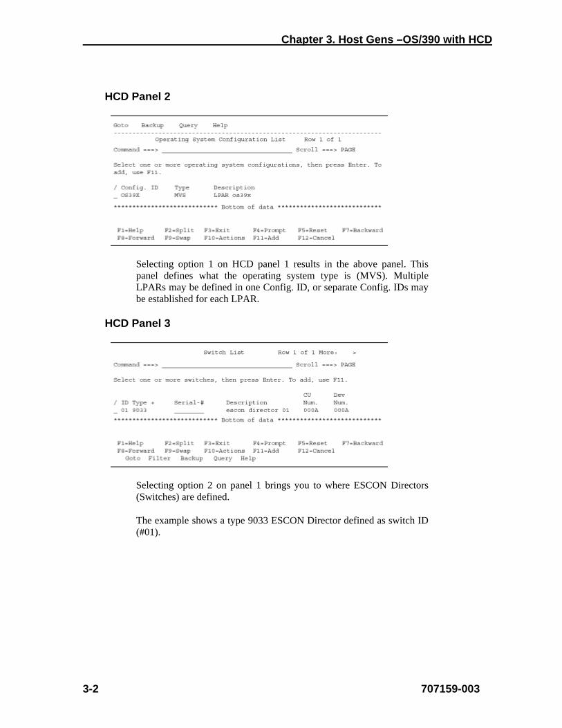
HCD Panel 2
Selecting option 1 on HCD panel 1 results in the above panel. This panel defines what the operating system type is (MVS). Multiple LPARs may be defined in one Config. ID, or separate Config. IDs may be established for each LPAR.
HCD Panel 3
Selecting option 2 on panel 1 brings you to where ESCON Directors (Switches) are defined.
The example shows a type 9033 ESCON Director defined as switch ID (#01).
CCA-3074 Planning
707159-003 3-3
HCD Panel 4
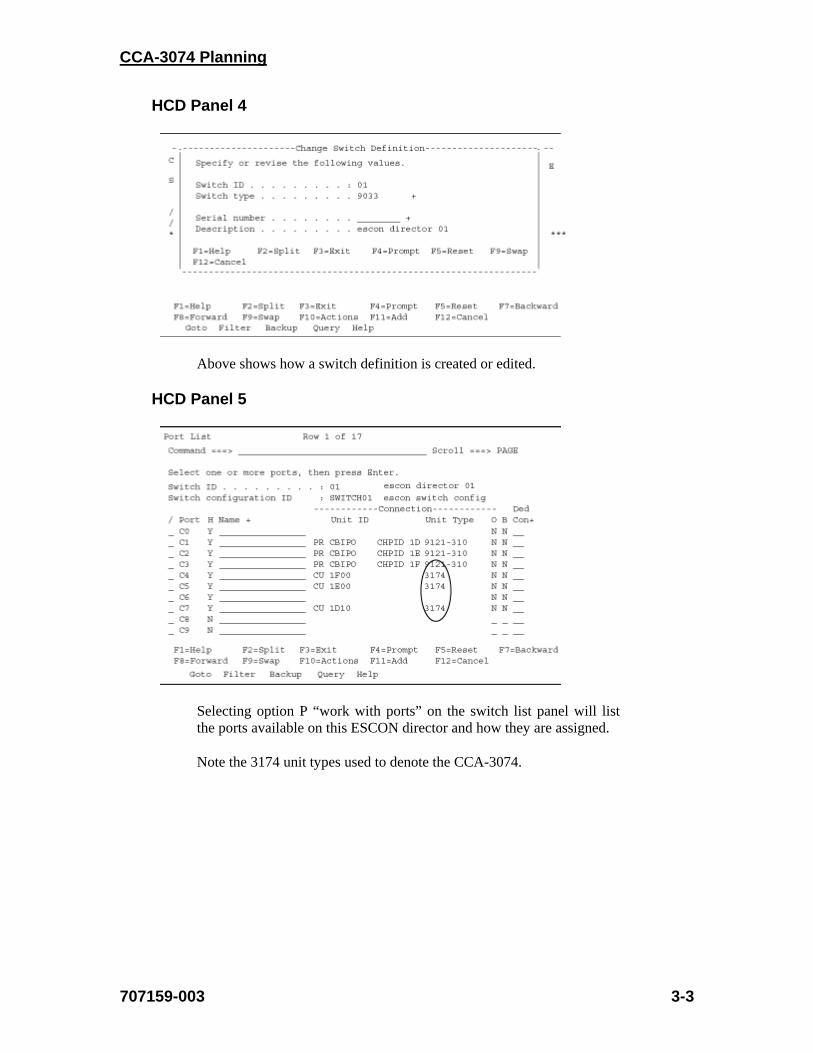
Above shows how a switch definition is created or edited.
HCD Panel 5
Selecting option P “work with ports” on the switch list panel will list the ports available on this ESCON director and how they are assigned.
Note the 3174 unit types used to denote the CCA-3074.
Chapter 3. Host Gens –OS/390 with HCD
3-4 707159-003
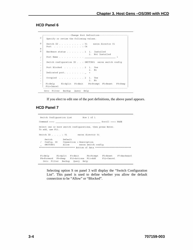
HCD Panel 6
If you elect to edit one of the port definitions, the above panel appears.
HCD Panel 7
Selecting option S on panel 3 will display the “Switch Configuration List”. This panel is used to define whether you allow the default connection to be “Allow” or “Blocked”.

CCA-3074 Planning
707159-003 3-5
HCD Panel 8
Select option S on panel 7. This panel allows you to override the default connection: “Allow”, and specify block on a per (switch) port basis.
HCD Panel 9
You can view/edit/define what is connected to each port on the switch.

Chapter 3. Host Gens –OS/390 with HCD
3-6 707159-003
HCD Panel 10
The panel shown above is obtained by selecting option 3 on HCD panel 1. This panel is where we define our processor and whether this processor is in LPAR MODE or in BASIC MODE (BASIC MODE means partitioning is turned off).
HCD Panel 11
From this panel, you can select to work with the partitions.
CCA-3074 Planning
707159-003 3-7
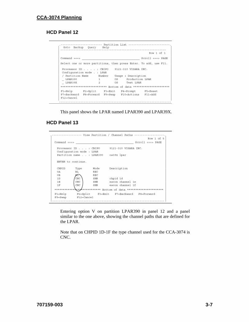
HCD Panel 12
This panel shows the LPAR named LPAR390 and LPAR39X.
HCD Panel 13
Entering option V on partition LPAR390 in panel 12 and a panel similar to the one above, showing the channel paths that are defined for the LPAR.
Note that on CHPID 1D-1F the type channel used for the CCA-3074 is CNC.
Chapter 3. Host Gens –OS/390 with HCD
3-8 707159-003
HCD Panel 14
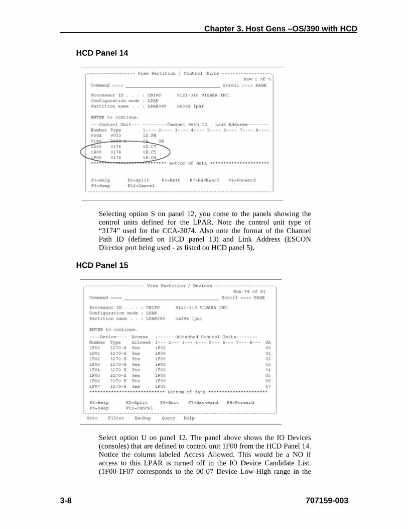
Selecting option S on panel 12, you come to the panels showing the control units defined for the LPAR. Note the control unit type of “3174” used for the CCA-3074. Also note the format of the Channel Path ID (defined on HCD panel 13) and Link Address (ESCON Director port being used - as listed on HCD panel 5).
HCD Panel 15
Select option U on panel 12. The panel above shows the IO Devices (consoles) that are defined to control unit 1F00 from the HCD Panel 14. Notice the column labeled Access Allowed. This would be a NO if access to this LPAR is turned off in the IO Device Candidate List. (1F00-1F07 corresponds to the 00-07 Device Low-High range in the
CCA-3074 Planning
707159-003 3-9
CCA-3074 configuration.
HCD Panel 16
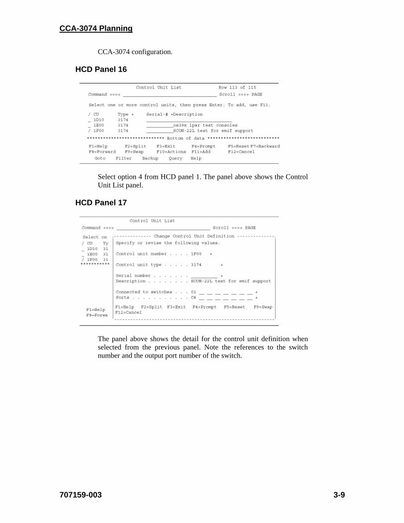
Select option 4 from HCD panel 1. The panel above shows the Control Unit List panel.
HCD Panel 17
The panel above shows the detail for the control unit definition when selected from the previous panel. Note the references to the switch number and the output port number of the switch.

Chapter 3. Host Gens –OS/390 with HCD
3-10 707159-003
HCD Panel 18
The parameter circled corresponds to the CUADD (CU address) parameter for the CCA-3074 over the ESCON interface (CU parameter in the CCA-3074 configuration).
HCD Panel 19
From the “Control Unit List” panel enter option V on control unit 1F00. This panel allows you to view the control unit definition for the CCA-3074.
CCA-3074 Planning
707159-003 3-11
HCD Panel 20
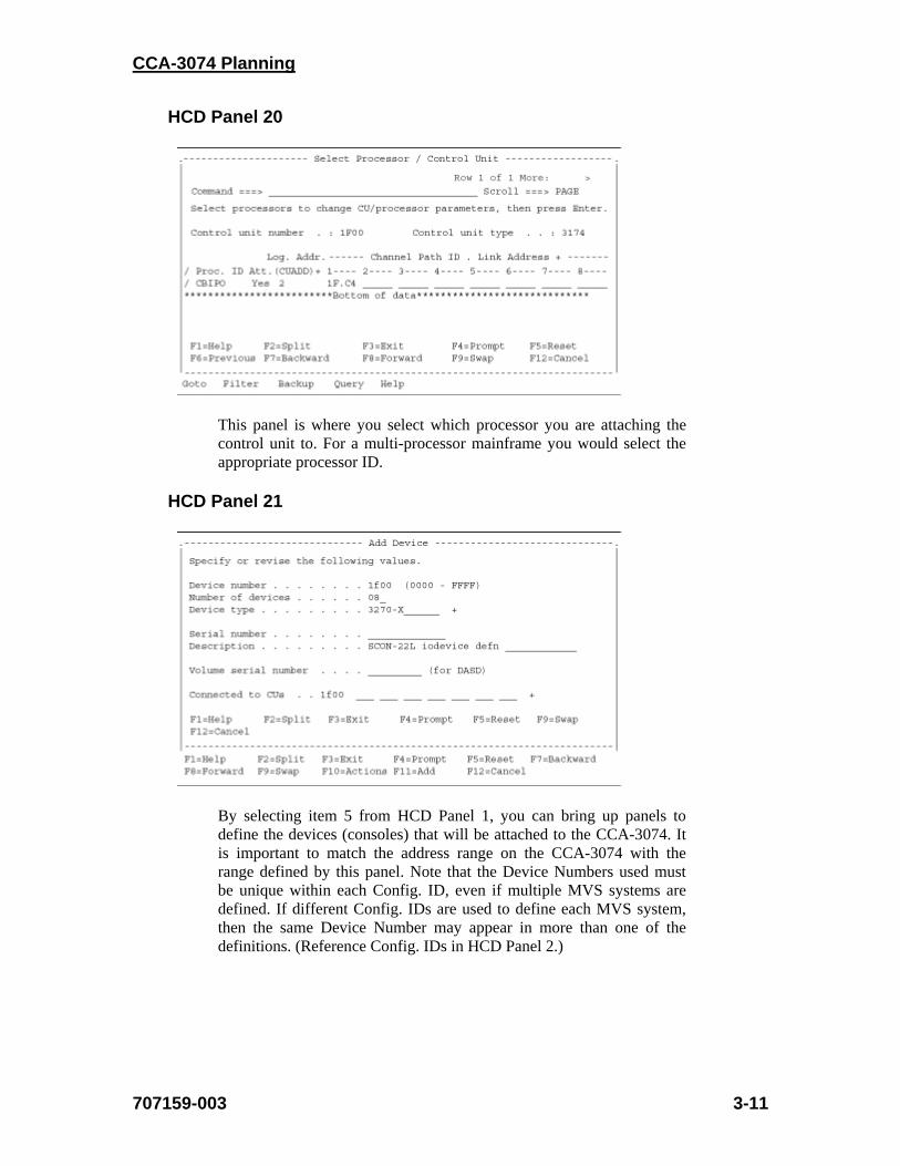
This panel is where you select which processor you are attaching the control unit to. For a multi-processor mainframe you would select the appropriate processor ID.
HCD Panel 21
By selecting item 5 from HCD Panel 1, you can bring up panels to define the devices (consoles) that will be attached to the CCA-3074. It is important to match the address range on the CCA-3074 with the range defined by this panel. Note that the Device Numbers used must be unique within each Config. ID, even if multiple MVS systems are defined. If different Config. IDs are used to define each MVS system, then the same Device Number may appear in more than one of the definitions. (Reference Config. IDs in HCD Panel 2.)
Chapter 3. Host Gens –OS/390 with HCD
3-12 707159-003
HCD Panel 22
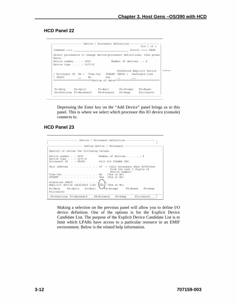
Depressing the Enter key on the “Add Device” panel brings us to this panel. This is where we select which processor this IO device (console) connects to.
HCD Panel 23
Making a selection on the previous panel will allow you to define I/O device definition. One of the options is for the Explicit Device Candidate List. The purpose of the Explicit Device Candidate List is to limit which LPARs have access to a particular resource in an EMIF environment. Below is the related help information.
CCA-3074 Planning
707159-003 3-13
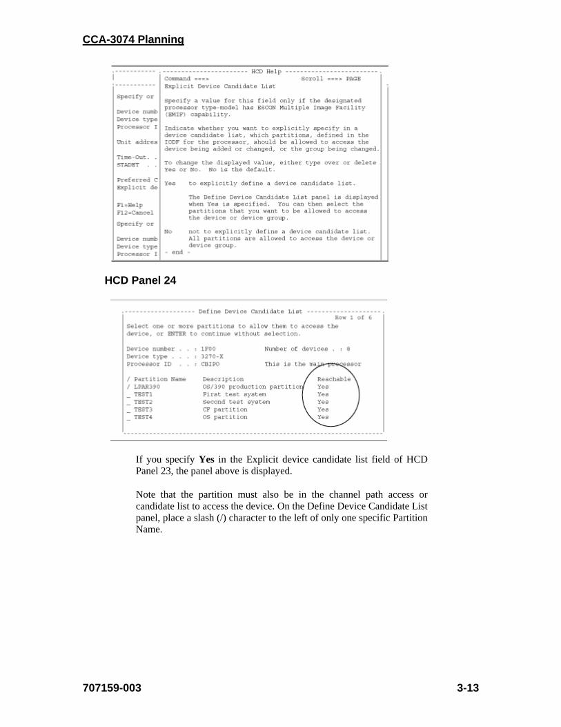
HCD Panel 24
If you specify Yes in the Explicit device candidate list field of HCD Panel 23, the panel above is displayed.
Note that the partition must also be in the channel path access or candidate list to access the device. On the Define Device Candidate List panel, place a slash (/) character to the left of only one specific Partition Name.
Chapter 3. Host Gens –OS/390 with HCD
3-14 707159-003
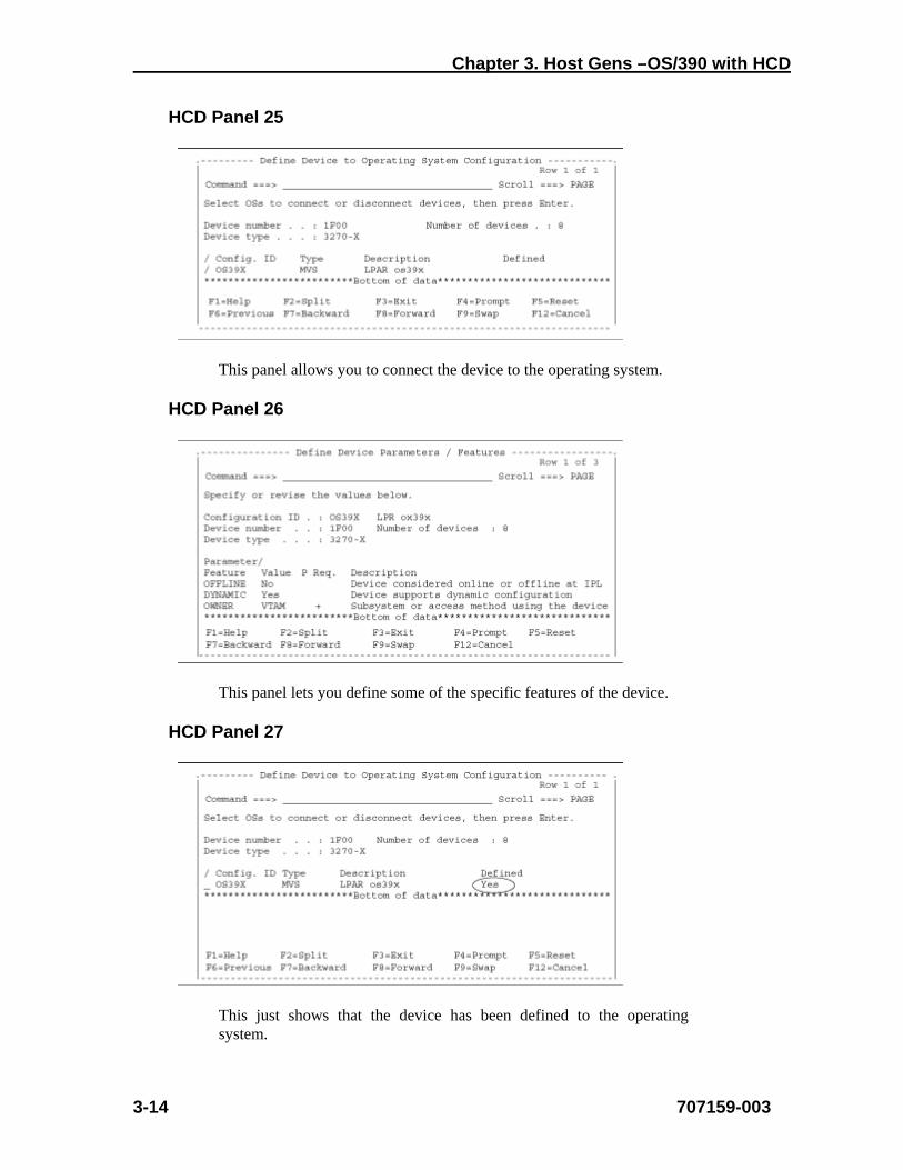
HCD Panel 25
This panel allows you to connect the device to the operating system.
HCD Panel 26
This panel lets you define some of the specific features of the device.
HCD Panel 27
This just shows that the device has been defined to the operating system.

CCA-3074 Planning
707159-003 3-15
HCD Panel 28
This just shows the 8 IO Devices you just created.
HCD Panel 29
This panel shows what you would see if you tried to configure an “Explicit device candidate list” on a processor that does not support EMIF.

CCA-3074 Planning
707159-003 4-1
Chapter 4. IOCDS Sample Definitions
Following are some example IOCDS definitions. Detailed examples of the corresponding HCD panels are not practical, due to the large number of panels required to create one of these definitions. Refer to the sample HCD panels in Chapter 3, and to the parameter cross reference chart in Chapter 2, to aid in determining what to define in the HCD panels.
Here are some of the key parameters used in the definitions for the CCA-3074, and what their purpose is.
CHPID
• PATH=number identifies which host ESCON/FICON connection is used
• TYPE=CNC required for ESCON • TYPE=FC required for FICON • SWITCH=number identifies an ESCON/FICON Director as
being in the channel path
CNTLUNIT -
• LINK=number identifies the ESCON/FICON Director port that the controller is attached to
• PATH argument allows association of the PATH to the LINK
• UNIT=3174 for ESCON definitions
• UNIT=NOCHECK for FICON definitions
IODEVICE - Basically the same as for Bus and Tag with addition of the following:
• PARTITION identifies which partition the definition is assigned to. Note that if no PARTITION parameter is specified, then the IODEVICE statement applies to all partitions sharing the CHPID (and the CNTLUNIT macro also applies to each). When this is the situation, the single set of statements is actually defining a CU in each of the LPARs with identical addressing. The CCA-3074 in turn, must have a separate CU defined to each of the LPARS sharing the path, and a separate set of definitions for the device sessions, etc.
Chapter 4. IOCDS Sample Definitions
4-2 707159-003
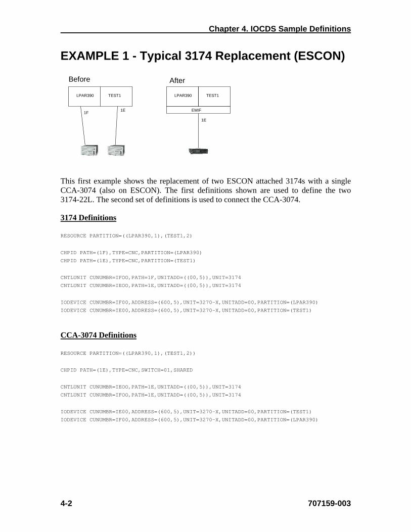
EXAMPLE 1 - Typical 3174 Replacement (ESCON)
This first example shows the replacement of two ESCON attached 3174s with a single CCA-3074 (also on ESCON). The first definitions shown are used to define the two 3174-22L. The second set of definitions is used to connect the CCA-3074.
3174 Definitions
RESOURCE PARTITION=((LPAR390,1),(TEST1,2)
CHPID PATH=(1F),TYPE=CNC,PARTITION=(LPAR390)
CHPID PATH=(1E),TYPE=CNC,PARTITION=(TEST1)
CNTLUNIT CUNUMBR=IFOO,PATH=1F,UNITADD=((00,5)),UNIT=3174
CNTLUNIT CUNUMBR=IEOO,PATH=1E,UNITADD=((00,5)),UNIT=3174
IODEVICE CUNUMBR=IF00,ADDRESS=(600,5),UNIT=3270-X,UNITADD=00,PARTITION=(LPAR390)
IODEVICE CUNUMBR=IE00,ADDRESS=(600,5),UNIT=3270-X,UNITADD=00,PARTITION=(TEST1)
CCA-3074 Definitions
RESOURCE PARTITION=((LPAR390,1),(TEST1,2))
CHPID PATH=(1E),TYPE=CNC,SWITCH=01,SHARED
CNTLUNIT CUNUMBR=IEOO,PATH=1E,UNITADD=((00,5)),UNIT=3174
CNTLUNIT CUNUMBR=IFOO,PATH=1E,UNITADD=((00,5)),UNIT=3174
IODEVICE CUNUMBR=IE00,ADDRESS=(600,5),UNIT=3270-X,UNITADD=00,PARTITION=(TEST1)
IODEVICE CUNUMBR=IF00,ADDRESS=(600,5),UNIT=3270-X,UNITADD=00,PARTITION=(LPAR390)
LPAR390 TEST1
1E1F
LPAR390 TEST1
1E
EMIF
Before After
CCA-3074 Planning
707159-003 4-3
Notes:
1. EMIF is used to allow both CNTLUNITs to share the same path (1E). 2. The CNTLUNIT macros do not include the CUADD parameter, and the default
value of “0” is assumed. 3. EMIF only allows LPARs within the same LCSS to share a channel. If multiple
LCSS’ are in use on a single mainframe, then an ESCON channel from each LCSS in use is required.
4. Up to 15 LPARs can be configured to share a single EMIF channel from the host. 5. The Device Candidate List in HCD is used to specify which LPARs are accessing
each CU.

Chapter 4. IOCDS Sample Definitions
4-4 707159-003
EXAMPLE 2 - Typical 3174 Replacement (FICON)
This example shows the replacement of the same two ESCON attached 3174s from Example 1, with a single CCA-3074 (this time on FICON). The definitions for the two 3174-22L were given in Example 1. The definitions below are used to connect the CCA-3074 through FICON.
CCA-3074 Definitions
RESOURCE PARTITION=((LPAR390,1),(TEST1,2))
CHPID PATH=(1E),TYPE=FC,SWITCH=01,SHARED
CNTLUNIT CUNUMBR=IEOO,PATH=1E,UNITADD=((00,5)),UNIT=NOCHECK
CNTLUNIT CUNUMBR=IFOO,PATH=1E,UNITADD=((00,5)),UNIT=NOCHECK
IODEVICE CUNUMBR=IE00,ADDRESS=(600,5),UNIT=3270-X,UNITADD=00,PARTITION=(TEST1)
IODEVICE CUNUMBR=IF00,ADDRESS=(600,5),UNIT=3270-X,UNITADD=00,PARTITION=(LPAR390)
Notes:
1. MIF is used to allow both CNTLUNITs to share the same path (1E). 2. The CNTLUNIT macros do not include the CUADD parameter, and the default
value of “0” is assumed. FICON and MIF allow multiple LCSS to be spanned. When spanning multiple LCSS a two-digit CUADD must be used.
3. This time the CHPID type is FC (FICON) 4. Note that the UNIT type has changed to ‘NOCHECK’. TYPE=3174 is not valid in the
FICON environment.
LPAR390 TEST1
1E1F
LPAR390 TEST1
1E
MIF
Before After
CCA-3074 Planning
707159-003 4-5
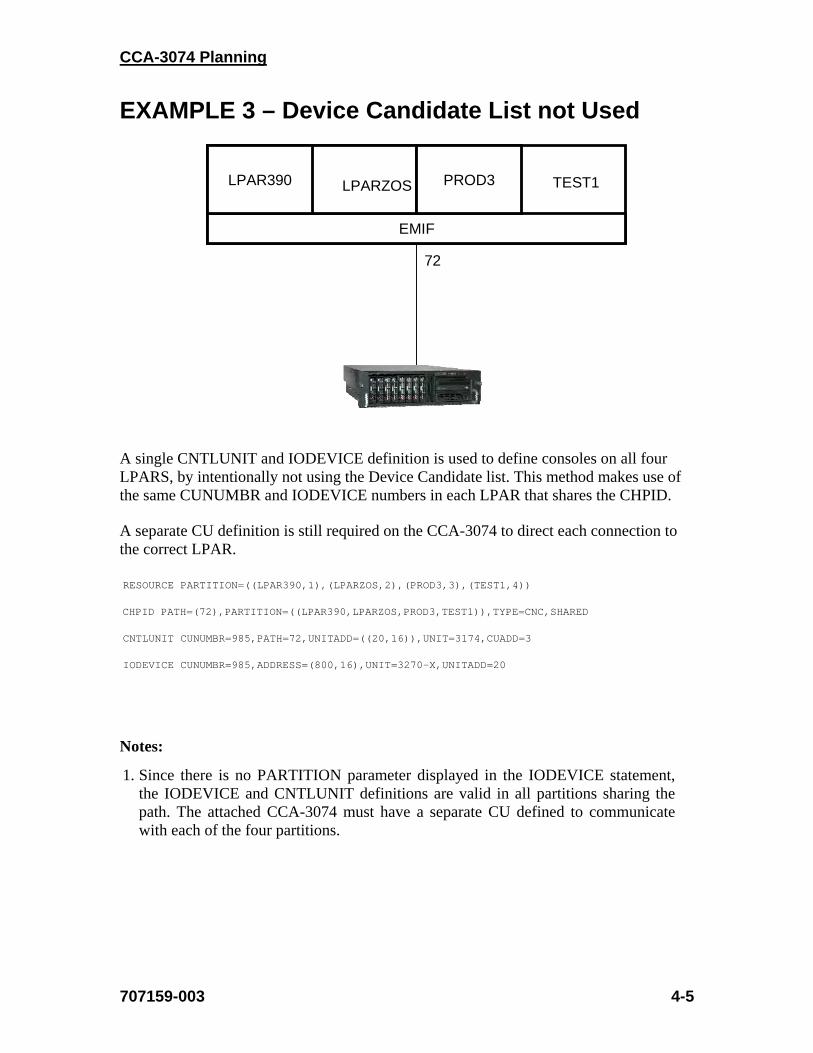
EXAMPLE 3 – Device Candidate List not Used
A single CNTLUNIT and IODEVICE definition is used to define consoles on all four LPARS, by intentionally not using the Device Candidate list. This method makes use of the same CUNUMBR and IODEVICE numbers in each LPAR that shares the CHPID.
A separate CU definition is still required on the CCA-3074 to direct each connection to the correct LPAR.
RESOURCE PARTITION=((LPAR390,1),(LPARZOS,2),(PROD3,3),(TEST1,4))
CHPID PATH=(72),PARTITION=((LPAR390,LPARZOS,PROD3,TEST1)),TYPE=CNC,SHARED
CNTLUNIT CUNUMBR=985,PATH=72,UNITADD=((20,16)),UNIT=3174,CUADD=3
IODEVICE CUNUMBR=985,ADDRESS=(800,16),UNIT=3270-X,UNITADD=20
Notes:
1. Since there is no PARTITION parameter displayed in the IODEVICE statement, the IODEVICE and CNTLUNIT definitions are valid in all partitions sharing the path. The attached CCA-3074 must have a separate CU defined to communicate with each of the four partitions.
EMIF
LPAR390 PROD3LPARZOS TEST1
72
Chapter 4. IOCDS Sample Definitions
4-6 707159-003
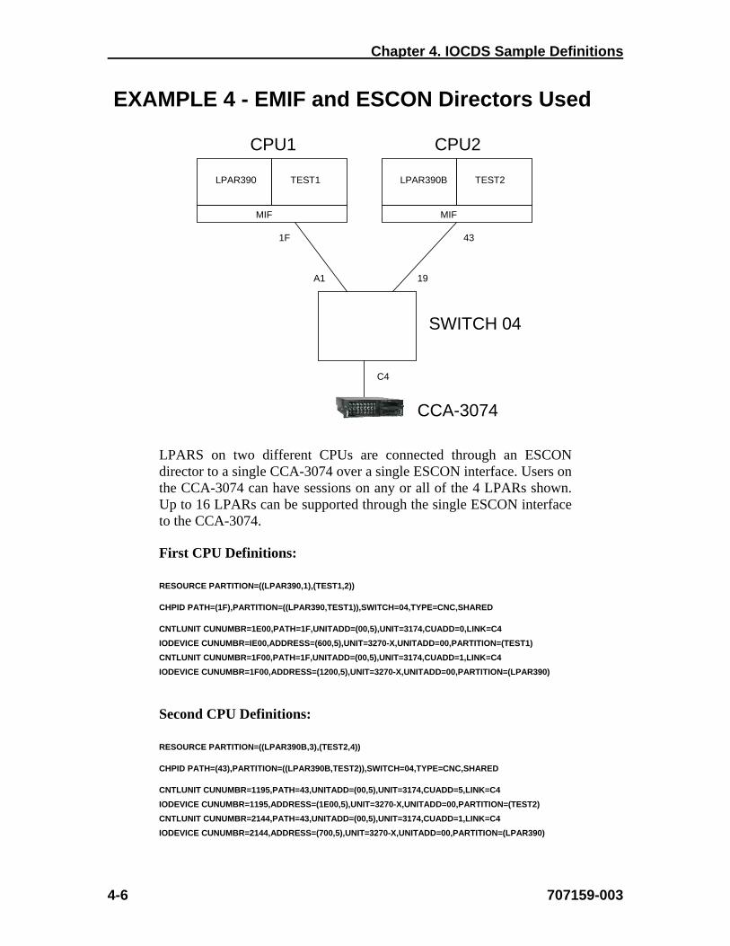
EXAMPLE 4 - EMIF and ESCON Directors Used
LPARS on two different CPUs are connected through an ESCON director to a single CCA-3074 over a single ESCON interface. Users on the CCA-3074 can have sessions on any or all of the 4 LPARs shown. Up to 16 LPARs can be supported through the single ESCON interface to the CCA-3074.
First CPU Definitions:
RESOURCE PARTITION=((LPAR390,1),(TEST1,2))
CHPID PATH=(1F),PARTITION=((LPAR390,TEST1)),SWITCH=04,TYPE=CNC,SHARED
CNTLUNIT CUNUMBR=1E00,PATH=1F,UNITADD=(00,5),UNIT=3174,CUADD=0,LINK=C4
IODEVICE CUNUMBR=IE00,ADDRESS=(600,5),UNIT=3270-X,UNITADD=00,PARTITION=(TEST1)
CNTLUNIT CUNUMBR=1F00,PATH=1F,UNITADD=(00,5),UNIT=3174,CUADD=1,LINK=C4
IODEVICE CUNUMBR=1F00,ADDRESS=(1200,5),UNIT=3270-X,UNITADD=00,PARTITION=(LPAR390)
Second CPU Definitions:
RESOURCE PARTITION=((LPAR390B,3),(TEST2,4))
CHPID PATH=(43),PARTITION=((LPAR390B,TEST2)),SWITCH=04,TYPE=CNC,SHARED
CNTLUNIT CUNUMBR=1195,PATH=43,UNITADD=(00,5),UNIT=3174,CUADD=5,LINK=C4
IODEVICE CUNUMBR=1195,ADDRESS=(1E00,5),UNIT=3270-X,UNITADD=00,PARTITION=(TEST2)
CNTLUNIT CUNUMBR=2144,PATH=43,UNITADD=(00,5),UNIT=3174,CUADD=1,LINK=C4
IODEVICE CUNUMBR=2144,ADDRESS=(700,5),UNIT=3270-X,UNITADD=00,PARTITION=(LPAR390)
LPAR390B TEST2
43
MIF
CPU2
LPAR390 TEST1
1F
MIF
CPU1
SWITCH 04
C4
A1 19
CCA-3074

CCA-3074 Planning
707159-003 4-7
Notes:
1. Different CUADD values are shown for each definition, but they are not required to be different with the CCA-3074.
2. LINK=C4 in the IO gen refers to the port that the CCA-3074 is connected to.
Chapter 4. IOCDS Sample Definitions
4-8 707159-003
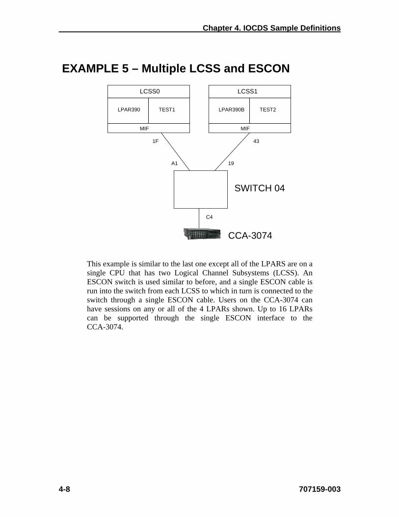
EXAMPLE 5 – Multiple LCSS and ESCON
This example is similar to the last one except all of the LPARS are on a single CPU that has two Logical Channel Subsystems (LCSS). An ESCON switch is used similar to before, and a single ESCON cable is run into the switch from each LCSS to which in turn is connected to the switch through a single ESCON cable. Users on the CCA-3074 can have sessions on any or all of the 4 LPARs shown. Up to 16 LPARs can be supported through the single ESCON interface to the CCA-3074.
LPAR390B TEST2
43
MIF
LPAR390 TEST1
1F
MIF
SWITCH 04
C4
A1 19
CCA-3074
LCSS0 LCSS1

CCA-3074 Planning
707159-003 4-9
IO Definitions:
RESOURCE PARTITION=((CSS(0),(LPAR390,1),(TEST1,2)),(CSS(1), (LPAR390B,3),(TEST2,4)))
CHPID PATH=(CSS(0),1F),PARTITION=((LPAR390,TEST1)),SWITCH=04,TYPE=CNC,PCHID=1C0,SHARED
CHPID PATH=(CSS(1),43),PARTITION=((LPAR390B,TEST2)),SWITCH=04,TYPE=CNC,PCHID=145, *
SHARED
CNTLUNIT CUNUMBR=1E00,PATH=(CSS(0),1F),UNITADD=(00,5),UNIT=3174,CUADD=0, *
LINK=(CSS(0),C4)
IODEVICE CUNUMBR=IE00,ADDRESS=(600,5),UNIT=3270-X,UNITADD=00,PARTITION=(CSS(0),TEST1)
CNTLUNIT CUNUMBR=1F00,PATH=(CSS(0),1F),UNITADD=(00,5),UNIT=3174,CUADD=1, *
LINK=(CSS(0),C4)
IODEVICE CUNUMBR=1F00,ADDRESS=(1200,5),UNIT=3270-X,UNITADD=00, *
PARTITION=(CSS(0),LPAR390)
CNTLUNIT CUNUMBR=1195,PATH=(CSS(1),43),UNITADD=(00,5),UNIT=3174,CUADD=5,LINK=(CSS(1),C4)
IODEVICE CUNUMBR=1195,ADDRESS=(1E00,5),UNIT=3270-X,UNITADD=00,PARTITION=(CSS(1),TEST2)
CNTLUNIT CUNUMBR=2144,PATH=(CSS(1),43),UNITADD=(00,5),UNIT=3174,CUADD=1,LINK=(CSS(1),C4)
IODEVICE CUNUMBR=2144,ADDRESS=(700,5),UNIT=3270-X,UNITADD=00,PARTITION=(CSS(1), *
LPAR390B)
Notes:
1. Each LCSS must have a separate ESCON cable into the switch. LPARs from different LCSS can not be MIF’d onto the same ESCON channel.
Chapter 4. IOCDS Sample Definitions
4-10 707159-003
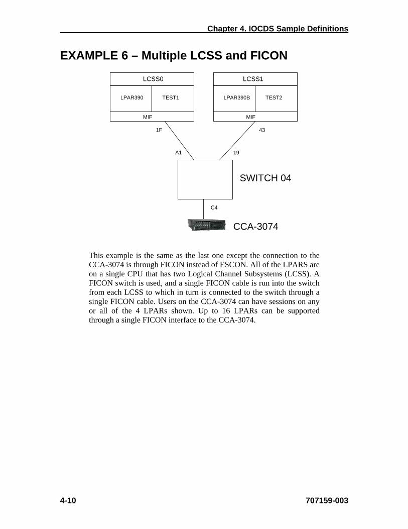
EXAMPLE 6 – Multiple LCSS and FICON
This example is the same as the last one except the connection to the CCA-3074 is through FICON instead of ESCON. All of the LPARS are on a single CPU that has two Logical Channel Subsystems (LCSS). A FICON switch is used, and a single FICON cable is run into the switch from each LCSS to which in turn is connected to the switch through a single FICON cable. Users on the CCA-3074 can have sessions on any or all of the 4 LPARs shown. Up to 16 LPARs can be supported through a single FICON interface to the CCA-3074.
LPAR390B TEST2
43
MIF
LPAR390 TEST1
1F
MIF
SWITCH 04
C4
A1 19
CCA-3074
LCSS0 LCSS1

CCA-3074 Planning
707159-003 4-11
IO Definitions:
RESOURCE PARTITION=((CSS(0),(LPAR390,1),(TEST1,2)),(CSS(1), (LPAR390B,3),(TEST2,4)))
CHPID PATH=(CSS(0),1F),PARTITION=((LPAR390,TEST1)),SWITCH=04,TYPE=FC,PCHID=1C0,SHARED
CHPID PATH=(CSS(1),43),PARTITION=((LPAR390B,TEST2)),SWITCH=04,TYPE=FC,PCHID=145, *
SHARED
CNTLUNIT CUNUMBR=1E00,PATH=(CSS(0),1F),UNITADD=(00,5),UNIT=NOCHECK,CUADD=0, *
LINK=(CSS(0),C4)
IODEVICE CUNUMBR=IE00,ADDRESS=(600,5),UNIT=3270-X,UNITADD=00,PARTITION=(CSS(0),TEST1)
CNTLUNIT CUNUMBR=1F00,PATH=(CSS(0),1F),UNITADD=(00,5),UNIT=NOCHECK,CUADD=1, *
LINK=(CSS(0),C4)
IODEVICE CUNUMBR=1F00,ADDRESS=(1200,5),UNIT=3270-X,UNITADD=00, *
PARTITION=(CSS(0),LPAR390)
CNTLUNIT CUNUMBR=1195,PATH=(CSS(1),43),UNITADD=(00,5),UNIT=NOCHECK,CUADD=5, *
LINK=(CSS(1),C4)
IODEVICE CUNUMBR=1195,ADDRESS=(1E00,5),UNIT=3270-X,UNITADD=00,PARTITION=(CSS(1),TEST2)
CNTLUNIT CUNUMBR=2144,PATH=(CSS(1),43),UNITADD=(00,5),UNIT=NOCHECK,CUADD=1, *
LINK=(CSS(1),C4)
IODEVICE CUNUMBR=2144,ADDRESS=(700,5),UNIT=3270-X,UNITADD=00,PARTITION=(CSS(1), *
LPAR390B)
Notes:
1. CHPID TYPE=FC is used for FICON as compared to the TYPE=CNC used for ESCON.
2. For FICON you must use UNIT=NOCHECK in the CNTLUNIT macros in place of the UNIT=3174 used in the ESCON environment.
3. When the two LCSS are connected to the switch through separate CHPIDs, the CUADD value may be a single digit. When a spanned CHPID is used (two or more LCSS’s LPARs involved), the CUADD value should be two digits.
4. In addition to the information contained in the IOGEN, you will need two additional pieces of information to configure the CCA-3074. These are the port numbers on the FICON switch that the hosts are plugged into, sometime referred to as the host link address. In this case the numbers are shown in the diagram and are ‘A1’ for LPARs LPAR390 and TEST1, and ‘19’ for LPARs LPAR390B and TEST2. The second piece of information that is needed is the FICON Domain ID or Switch Domain ID that is assigned to the FICON switch that the hosts are connected to. Note that if two FICON switches are cascaded, the information is for the one(s) that the hosts are connected to, not the one that the CCA-3074 is connected to.


CCA-3074 Planning
707159-003 5-1
Chapter 5. CSS32 External Coax Subsystem
What is the External Coax Subsystem? The CCA-3074 does not support coax ports directly attached to the platform. To accommodate coax connectivity, an external CSS32 Coax Subsystem can be interfaced to the CCA-3074. The external CSS32 Coax Subsystem is a Visara LINCS based product. The CSS32 communicates with the CCA-3074 over an IP network using TN3270E protocol for display or LMU sessions, and using LPD/LPR protocol for printer sessions. The network connection can be as simple as a RJ45 crossover cable interconnecting the two platforms mounted in the same 19” rack or the two platforms can be remotely linked through a corporate Intranet or even across the Internet (preferably through a VPN). The relationship between the CCA-3074 and its satellite(s) does not have to be one on one. That is, one CCA-3074 can support multiple Coax Subsystems, and a single Coax Subsystem can communicate with multiple CCA-3074s. CSS32 Factory Default Configuration The CSS32 comes with a standard factory default configuration. This configuration is designed to support the CSS32 attached to the CCA-3074 through a crossover cable. The default configuration will support up to 31 coax display or LMU sessions (one session for each of 31 coax ports) and one printer session. For more complex requirements for the CSS32, changes to the factory default configuration will be needed. For more details about the specifics of the factory default configuration of the CSS32 please refer to Appendix A in the CCA-3074 Installation and Configuration Manual.


CCA-3074 Planning
707159-003 6-1
Chapter 6. Frequently Asked Questions
Q: Does the CCA-3074 support SNA over ESCON or FICON?
A: No. The CCA-3074 is dedicated to supporting Non-SNA communications over ESCON and FICON. If SNA communications is required, you may use the CNA-8000 product instead. The CNA-8000 is capable of supporting SNA communications over ESCON and FICON.
Q: Does the CCA-3074 support Bus and Tag connections? A: No.
Q: Can you attach coax terminals to the CCA-3074? A: The CCA-3074 does not support coax ports directly. You
can support coax terminals, printers, and LMU connections through use of the external CSS32 Coax Subsystem.
Q: Can you attach StorageTek Silos to the CCA-3074. A: The LMU (Library Management Unit) used to manage
the Silos will attach to the external CSS32 Coax Subsystem using coax connections.
Q: Is there any way to remotely manage the CCA-3074? A: Yes. CCA-3074 management is through a browser
interface. The biggest concern for remote management is probably security. The CCA-3074 browser is a secure connection making use of https (SSL encryption) between the workstation running the browser session and the CCA-3074.
Q: Does the CCA-3074 support VPNs? A: No, not directly. You can use external products to provide
the Virtual Private Network security. However, SSL encryption is supported directly, which provides encryption from the user desktop to the CCA-3074. The question becomes do you really need a VPN connection. In most cases you probably do not.
Q: Does the CCA-3074 support Secure Socket Layer communication over the network?
A: Yes. You can configure the CCA-3074 to communicate SSL encryption directly to the remote client desktops.

Chapter 6. Frequently Asked Questions
6-2 707159-003
Q: Does the CCA-3074 support international languages? A: No. All host communication and browser management
interface makes use of English.
Q: Does the CCA-3074 have any provisions for redundancy? A: The CCA-3074 supports 2 ESCON interfaces and 4
FICON interfaces, allowing you to provide multiple paths to your LPARs. The two ESCON interfaces are on separate cards. The four FICON interfaces can be implemented with one or two FICON cards. The CCA-3074 also makes use of redundant, independently configurable power supplies, redundant cooling fans, and redundant hard drives that use RAID mirroring.
Q: Does the CCA-3074 support all TN3270E clients. A: Yes, for the most part. All of the more popular emulators,
as well as many more obscure ones will work. There is nothing about the TN3270E (RFC 1647) interface or the older TN3270 (RFC 1576) that should eliminate any specific client. You may however wish to contact a Visara representative for a list of PC emulations that are known to work as consoles.
Q: Does the CCA-3074 support a FICON interface? A: Yes. You can connect the CCA-3074 to a FICON channel
either point to point to a CPU or through a Director. Both Long Wave (single-mode fiber) and Short Wave (multimode fiber) is supported (you must request the correct transceivers for your environment when you order).
Q: Is 1 Gbps FICON supported? A: No. The FICON adapter used by the CCA-3074 supports
2Gbps, 4Gbps, and 8Gbps FICON.
Q: Does the CCA-3074 support NIP consoles? A: Yes. You can define NIP and MCS (MVS) consoles to
the CCA-3074. It is good planning to define multiple NIP consoles, spread across more than one CCA-3074 for redundancy sake.
CCA-3074 Planning
707159-003 6-3
Q: If there is a power failure, will the CCA-3074 automatically recover?
A: Yes. First of all, the CCA-3074 has dual power feeds, and if plugged into multiple mains, the chance of a power failure can be minimized. However, if you have all lines plugged into the same power source and there is a failure, the CCA-3074 should power back up and automatically go online when the power failure is over. The boot process should be complete within about 5 minutes. It will probably be necessary to vary the console sessions active again, since a failed console connection will normally roll to another console on another platform if available or to the support element.
Q: Can you change the configuration of one LPAR on the CCA-3074, or add a new LPAR definition without performing a reboot?
A: Yes. The latest server software used by the CCA-3074 allows for you to dynamically change the host connections as needed. To make the changes take affect you must offline the host CHPID, invoke the change, and online the CHPID. To maintain active consoles while invoking changes it is still recommended to have redundant CCA-3074s. By having redundant CCA-3074s, you can take one down for periodic maintenance while the other CCA-3074 is providing critical services.
Q: Can you change TN3270E client settings without having to reboot or restart the CCA-3074?
A: Yes. You can make changes to TN3270E clients, which ports they connect to, whether encryption is supported, user IDs and passwords, pool definitions, etc. and apply the changes without having to reboot or restart the platform.
Q: Will a TN3270E client get a live console session when they connect in?
A: Only if the Hot Session option is configured on the CCA-3074. Otherwise, if the client is not connected when the LPAR first comes up, the device is reported as being powered off, and the console session would roll to the alternate console or to the support element.
Chapter 6. Frequently Asked Questions
6-4 707159-003
Q: How does the Hot Console Session feature work? A: The CCA-3074 treats a Hot Console Session as if the
device were always powered up. Console messages are received and discarded by the CCA-3074 when no client is connected to the session. When a client does connect to the session, a Clear AID is sent inbound automatically to cause the host to repaint the latest screen to the client.
Q: Can a console operator retrieve messages discarded by the CCA-3074 from a Hot Session?
A: No, not directly from the CCA-3074. You would need to access the SDSF, on the host. Visara also offers another product, the MCC (Master Console Center), which can provide console session logging and retrieval among its many features. The MCC can be integrated with the CCA-3074 on the same platform to reduce footprint if desired.
Q: Can I configure a combination of regular console sessions and Hot Console sessions?
A: Yes. You can determine which sessions need to be hot and which ones do not.
Q: Does the CCA-3074 support some way to track what users connect to the platform?
A: Yes. The CCA-3074 keeps a sessions log which logs when users connect to the CCA-3074, disconnect from the CCA-3074, and when a failed attempt to get a session from the CCA-3074 occurs. The size of the file kept or how long it is kept is configurable.
Q: Does the CCA-3074 support Long Wave (single-mode fiber) or Short Wave (multimode fiber) FICON?
A: The CCA-3074 can support either environment, but you must order it for whichever you are using in your environment.
Q: Can I mix Long Wave (single-mode fiber) and Short Wave (multimode fiber) FICON on the CCA-3074?
A: The CCA-3074 can support either environment, but you must order the interface for whichever you are using in your environment.
CCA-3074 Planning
707159-003 6-5
Q: Can I configure Hot VTAM sessions? A: In general, you do not need to. The host should detect
when a VTAM terminal powers up, and provide the user with a new session. Configuring a VTAM session as a hot session on the CCA-3074 may result in unpredictable results.
Q: How do I make a Hot Session roll to another terminal? A: Do not configure a Hot Session if you need it to roll to
another terminal automatically. If you need to switch control of a console to another device you can use normal console commands to disable a console and activate a different console. Of course if the CCA-3074 powers down, or otherwise stops communicating with the host, all console sessions will automatically roll to their alternates or to the support element.
Q: Is it possible to share a console session between two or more operators.
A: Yes, the CCA-3074 supports a session sharing feature which can be configured. You can share a single session between multiple users at one time. All operators may enter console commands, and each of the operators sharing the session will see the results of the command entered. This option can be used for training, joint problem determination, and disaster recovery situations.
Q: Does the CCA-3074 support hot swappable cards? A: No. Only the power supplies, fans, and hard drives are hot
swappable.
Q: How many coax devices can be supported by a single CCA-3074?
A: Any or all of the sessions supported by the CCA-3074 can be realized as coax sessions if needed. Each CSS32 coax subsystem supports 32 physical coax devices. Multiple CSS32 coax subsystems can be connected to the CCA-3074. It is even possible to connect multiple coax devices to share a single console session if desired.
Q: Is it possible to run multiple console sessions from a single coax device?
A: Although the CSS32 is configured in the factory to support a single session from each coax device, it is possible to run as many as 10 concurrent sessions from a single coax device

Chapter 6. Frequently Asked Questions
6-6 707159-003
Q: How is the CSS32 coax subsystem connected to the CCA-3074?
A: The actual connection makes use of an Ethernet compatible twisted pair cable. By using a null crossover cable, the coax subsystem can be isolated from your corporate network providing additional reliability. Communication over this connection makes use of IP. You can also run the connection through any standard Ethernet switch or hub.
Q: Do I have any console support options if my network goes down?
A: Yes. There are four options to support consoles independent of your corporate network. 1) Use a separate network to support your TN3270 consoles from. Even if you need remote TN3270 client access, a separate local network with a few clients can provide emergency support for when the corporate network is down. 2) Use a CSS32 to provide coax terminals as an alternative to your network. The CSS32 may be connected directly to the CCA-3074. 3) With up to 10 separate Ethernet interfaces on the CCA-3074 you may directly attach a few clients independent of the network. 4) A directly attached monitor, keyboard, and mouse provides up to 10 console sessions to be run directly on the CCA-3074 without any external connections.
Q: How many LPARs can the CCA-3074 support consoles for?
A: The number of LPARs supported is limited by the number of host interfaces installed. Each ESCON interface supports as many as 16 LPARs. Two ESCON interfaces are supported for a current total of 32 LPARs. The CCA-3074 supports up to four FICON interfaces in addition to the ESCON interfaces. This brings the total number of LPARs supported by the CCA-3074 to 96 LPARs.

CCA-3074 Planning
707159-003 A-1
Fu
nct
ion
Lis
ten
P
ort
3074
D
evic
e N
ame
IOD
EV
ICE
#
3074
C
U
Nam
e
3074
C
U #
3074
E
SC
ON
In
terf
ace
CN
TL
UN
IT
#
CU
AD
D
#
Hos
t P
arti
tion
N
ame
Dir
ecto
r P
ort
t #
to
30
74
Dir
ecto
r P
ort
# to
CP
U
Sw
itch
#
CH
PID
#
CP
U
Appendix A. Consoles Planning Worksheet
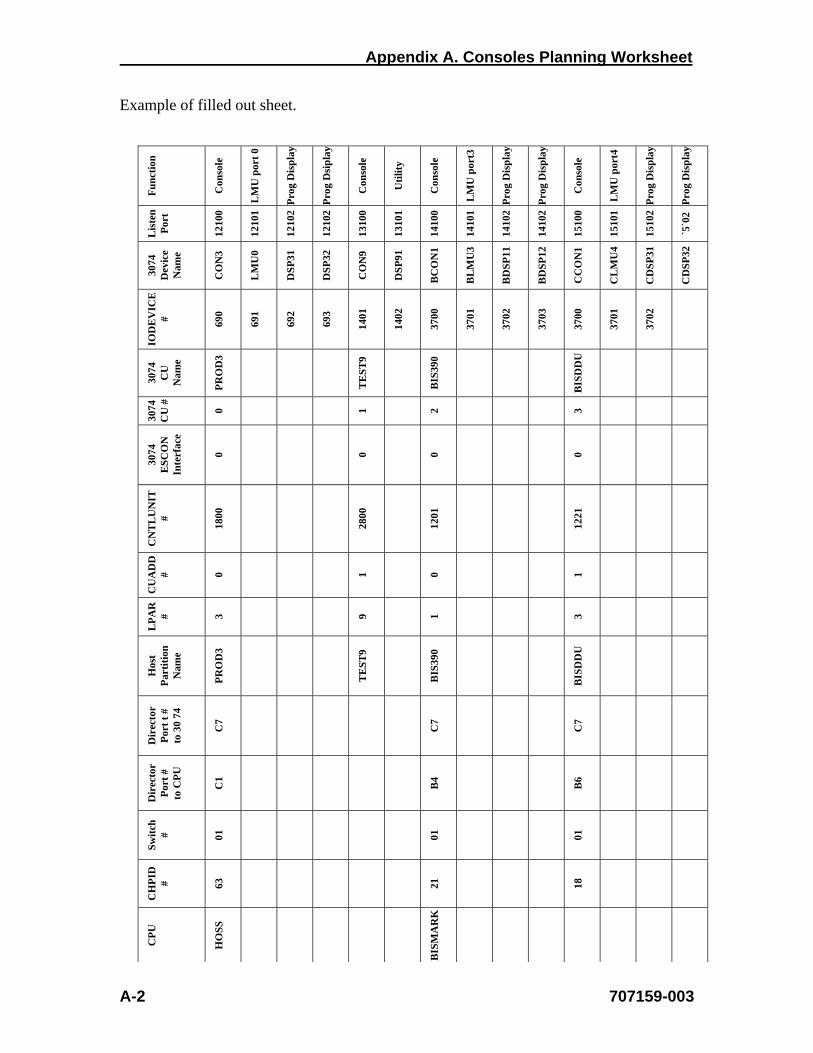
Appendix A. Consoles Planning Worksheet
A-2 707159-003
Fu
nct
ion
Con
sole
LM
U p
ort
0
Pro
g D
isp
lay
Pro
g D
sip
lay
Con
sole
Uti
lity
Con
sole
LM
U p
ort3
Pro
g D
isp
lay
Pro
g D
isp
lay
Con
sole
LM
U p
ort4
Pro
g D
isp
lay
Pro
g D
isp
lay
Lis
ten
P
ort
1210
0
1210
1
1210
2
1210
2
1310
0
1310
1
1410
0
1410
1
1410
2
1410
2
1510
0
1510
1
1510
2
`5`0
2
3074
D
evic
e N
ame
CO
N3
LM
U0
DS
P31
DS
P32
CO
N9
DS
P91
BC
ON
1
BL
MU
3
BD
SP
11
BD
SP
12
CC
ON
1
CL
MU
4
CD
SP
31
CD
SP
32
IOD
EV
ICE
# 69
0
691
692
693
1401
1402
3700
3701
3702
3703
3700
3701
3702
3074
C
U
Nam
e
PR
OD
3
TE
ST
9
BIS
390
BIS
DD
U
3074
C
U #
0 1 2 3
3074
E
SC
ON
In
terf
ace
0 0 0 0
CN
TL
UN
IT
#
1800
2800
1201
1221
CU
AD
D
# 0 1 0 1
LP
AR
# 3 9 1 3
Hos
t P
arti
tion
N
ame
PR
OD
3
TE
ST
9
BIS
390
BIS
DD
U
Dir
ecto
r P
ort
t #
to
30
74
C7
C7
C7
Dir
ecto
r P
ort
# to
CP
U
C1
B4
B6
Sw
itch
# 01
01 01
CH
PID
# 63
21 18
CP
U
HO
SS
BIS
MA
RK
Example of filled out sheet.