ccgs acquisition, llc ccgs finance, llcclerk/documents/...n:\technical\2753 city center realty\05...
TRANSCRIPT

Response Action Plan
Former Superior Plat ing Facility
315 1st Avenue NEMinneapolis, Minnesota
Prepared for
CCGS ACQUISITION, LLC
andCCGS
FINANCE, LLC
April 2012

Section 4 Constitutes Trade Secret and Nonpublic Data Until Bankruptcy Auction
Wenck File #2753-01-05
Prepared for:
CCGS ACQUISITION, LLC AND
CCGS FINANCE, LLC 800 Washington Avenue North
Suite 690 Minneapolis, MN 55401
ResponseAction Plan
Former SuperiorPlating Facility
315 1st Avenue NEMinneapolis, Minnesota
Prepared by:
WENCK ASSOCIATES, INC. 1802 Wooddale Drive
Suite 100 Woodbury, Minnesota 55125
(651) 294-4580
April 2012
N:\Technical\2753 City Center Realty\05 Grant applications\RAP\Revised RAP\RAP - April final041712.docx
i
Table of Contents
1.0 PURPOSE AND SCOPE.....................................................................................................1
2.0 SITE DESCRIPTION .........................................................................................................2
2.1 Site Location ............................................................................................................2 2.2 Site History ..............................................................................................................2 2.3 Current Site Conditions............................................................................................3 2.4 Site Physical Setting ................................................................................................4
2.4.1 Topography ................................................................................................4 2.4.2 Geology .....................................................................................................4 2.4.3 Hydrogeology ............................................................................................5
3.0 PAST INVESTIGATIONS AND ONGOING RESPONSE ACTIONS .........................6
3.1 General .....................................................................................................................6 3.2 Soil Impacts .............................................................................................................6 3.3 Groundwater Impacts and Ongoing Groundwater Treatment .................................7
3.2.1 South Groundwater Pump and Treat System ............................................7 3.3.2 Groundwater Seep Collection Trench .......................................................8
4.0 VOLUNTARY RESPONSE ACTION PLAN ..................................................................9
4.1 Rationale and Objectives .........................................................................................9 4.2 Chemicals of Concern and Numerical Cleanup Goals ............................................9 4.3 Site Preparation Activities .....................................................................................11 4.4 Soil Removal Actions, Block 16 ............................................................................13
4.4.1 Proposed Approach to Soil Removal Actions, Block 16 ........................14 4.4.1.1 Treatment Activities.................................................................15 4.4.1.2 Verification of Metals Stabilization .........................................16
4.4.2 Air Monitoring Activities ........................................................................16 4.4.3 Off-Site Transportation and Disposal ......................................................17 4.4.4 Completion of Demolition .......................................................................17
4.5 Soil Removal Actions, Block 13 ............................................................................18 4.5.1 Soil Removal Actions ..............................................................................18 4.5.2 Air Monitoring Activities ........................................................................19 4.5.3 Off-Site Transportation and Disposal ......................................................19 4.5.4 Site Restoration Activities .......................................................................20
4.6 Groundwater Remedy ............................................................................................20 4.6.1 Interim Actions, North Groundwater Seep ..............................................20 4.6.2 Interim Actions, South Groundwater Pump and Treat System ...............21 4.6.3 Groundwater Response Actions ..............................................................21

Table of Contents (Cont.)
N:\Technical\2753 City Center Realty\05 Grant applications\RAP\Revised RAP\RAP - April final041712.docx
ii
4.7 Vapor Intrusion and Screening Investigation ........................................................22 4.8 Vapor Mitigation ....................................................................................................23 4.9 Related Response Action Activities.......................................................................24
4.9.1 Health and Safety ....................................................................................24 4.9.2 Utility Clearance ......................................................................................24
5.0 CONSTRUCTION CONTINGENCY PLAN .................................................................25
5.1 General ...................................................................................................................25 5.2 Waste Evaluation ...................................................................................................25
5.2.1 Demolition Debris and General Refuse ...................................................26 5.2.2 Free Product .............................................................................................26 5.2.3 Underground Storage Tanks ....................................................................26 5.2.4 Barreled Wastes .......................................................................................27 5.2.5 Electrical Transformers ...........................................................................27 5.2.6 Creosote Timbers .....................................................................................27 5.2.7 Waste Tires ..............................................................................................28 5.2.8 Stained Soils or Soil Exhibiting Strong or Unusual Odors .....................28
5.3 Recognition of Potentially Hazardous Materials ...................................................28 5.4 Screening and Sampling of Contaminated Soil .....................................................30
5.4.1 Headspace Screening Procedure ..............................................................30 5.4.2 General Soil Sampling Procedures ..........................................................31 5.4.3 Sheen Test Procedure ..............................................................................33
5.5 Hazard Ealuation ....................................................................................................33 5.5.1 Chemical Vapor Hazards .........................................................................33 5.5.2 Particulate Hazards ..................................................................................33 5.5.3 Physical Hazards .....................................................................................34
6.0 VERIFICATION OF RESPONSE ACTION EFFECTIVENESS ................................35
6.1 General ...................................................................................................................35
7.0 VRAP IMPLEMENTATION REPORT .........................................................................36
8.0 SCHEDULE .......................................................................................................................37
9.0 REFERENCES ..................................................................................................................39
Table of Contents (Cont.)
N:\Technical\2753 City Center Realty\05 Grant applications\RAP\Revised RAP\RAP - April final041712.docx
iii
FIGURES 1 Site Location Map 2 Site Detail Map3 Monitoring Well Network4 Site Features5 Proposed Excavation Areas

N:\Technical\2753 City Center Realty\05 Grant applications\RAP\Revised RAP\RAP - April final041712.docx
1
1.0 Purpose and Scope
This document presents the proposed Response Action Plan (RAP) for the Superior Plating
property identified by its street address of 315 1st Avenue NE, Minneapolis, Minnesota (the Site).
The Site includes all but one lot of two city blocks, including the former road right-of-way
between the two blocks.
This RAP presents strategies for managing soil impacted by electroplating wastes and degreasing
solvents from beneath for former facility building on Block 16 when it is demolished, managing
soil impacted by demolition waste and other “junk fill” on Block 13, and undertaking the
maintenance of on-going response actions relative to impacted groundwater as described in the
Minnesota Decision Document (MDD), dated October 20, 1997.
Due to the nature of the Site as a listed Permanent List of Priorities (PLP) site, the project will
require public acceptance of the remedy. Therefore, a Community Relations Plan is an integral
component of this project. The Community Relations Plan will be prepared under a separate
cover and submitted for MPCA review. Public comment will be solicited on the presented plan,
and measures taken to ensure community concerns relative to the cleanup are appropriately
addressed.
Based on the recognized environmental conditions identified, Wenck prepared a Limited Phase
II Investigation Work Plan (Work Plan), dated December 2011. The Work Plan was approved by
Minnesota Pollution Control Agency (MPCA) Voluntary Investigation and Cleanup (VIC)
Program staff on January 18, 2012, by email correspondence.

N:\Technical\2753 City Center Realty\05 Grant applications\RAP\Revised RAP\RAP - April final041712.docx
2
2.0 Site Description
2.1 SITE LOCATION
The approximately 5.44 acres (236,866 square feet) property is in the NW ¼ of the NE ¼ of
Section 23, Township 29 North, Range 24 West. The Site consists of eight separate tax parcels
with the following Hennepin County Property Identification Numbers: 23-029-24-12-0090, 23-
029-24-12-0182, 23-029-24-12-0083, 23-029-24-12-0084, 23-029-24-12-0085, 23-029-24-12-
0080, 23-029-24-12-0079 and 23-029-24-12-0078. These parcels make up all of Block 16, and
Lots 2 through 10 of Block 13 of the St. Anthony Falls Addition to Minneapolis. (The Site is all
of the two blocks and the vacated street between, with the exception of Lot 1, Block 13.)
The Site location is shown in Figure 1. A Site Detail Map is shown in Figure 2.
2.2 SITE HISTORY
Based on the review of information provided in the December 2011 Phase I Environmental Site
Assessment (Wenck Associates, Inc.), Block 16 (the western block) of the Site was developed in
April of 1891 with a 198 by 330 foot “car barn.” The facility served the Minneapolis Rapid
Transit Street Railyard Company. It appears the building occupied the southern six lots of Block
16, and was expanded to cover the entire block in 1902. The building served the streetcar system
for at least half a century. By late 1954, what appears to have been a multi-year process of
converting the building for use as a painting, electroplating and polishing facility began. The
facility building has served as the headquarters for the Superior Plating facility since that at least
1955. At the time of the site reconnaissance, the facility was in the process of being
decommissioned, although several plating lines were still in production.

N:\Technical\2753 City Center Realty\05 Grant applications\RAP\Revised RAP\RAP - April final041712.docx
3
Development on Block 13 (the eastern half of the Site) is documented as far back as the earliest
reviewed historical maps (1892). Building permit records and historical maps indicate a variety
of uses in the late 19th and early 20th century, broadly including residential uses, rooming houses
and boarding houses along the 1st Avenue NE portion of the block, and commodities, including
lumber, produce and coal on the north portion of the block. Notably, a small filling station was
located on the southwest corner, Lot 10, Block 13, from 1935 until sometime prior to May 1971.
2.3 CURRENT SITE CONDITIONS
The Site consists of the majority of two city blocks separated by a vacated roadway. The western
block contains a large building, formerly used as an electroplating facility (Superior Plating).
The facility is being decommissioned, and no plating lines are currently being used for plating.
The plating line tanks and associated piping is in the process of being cleaned of residual impacts
in order to render them suitable for recycling as scrap metal. The east block contains a storage
building for the Superior Plating facility, as well as a surface parking lot. The east block also
contains an active automotive service facility on the southeastern-most lot, however, this is not
part of the Site.
The Superior Plating facility building still contains an operating wastewater treatment system
that is being used during the decommissioning process for processing cleaning wastewater
residues. The wastewater treatment system also processes the flow of an impacted groundwater
seep from beneath the northwest side of the plant building. There is a seep collection trench that
extends approximately 120 feet east-west, north of the west side of the plant building, parallel to
the existing, active railroad track. This seep collection trench, as well as a constructed retaining
wall area that contains the sump pump system, is located on a railroad lease area. The rear wall
of the electroplating facility is constructed on the parcel boundary.

N:\Technical\2753 City Center Realty\05 Grant applications\RAP\Revised RAP\RAP - April final041712.docx
4
2.4 SITE PHYSICAL SETTING
2.4.1 Topography
The Site is in an area of Minneapolis generally characterized by relatively level topography. The
south side of the Site is at street level. Topographic elevation at the Site is approximately 840
feet above mean sea level. Drainage is controlled by storm sewers adjacent to the Site, as well as
the railroad grade north of the Site. Regional drainage is to the south and east. Site topography is
controlled by the Platteville Limestone formation, a stratigraphic cap-rock feature that accounts
for the nearby St. Anthony Falls. Limestone quarries historically were located in the vicinity, and
it is probable that the gentle grade of the railroad track in its decent to the river crossing was a
man-made feature cut into the Platteville.
2.4.2 Geology
According to geologic source maps, surficial geology at the Site is described as Quaternary-aged
Middle Terrace deposits of the Minneapolis outwash plain. These deposits are characterized as
sand, gravely sand and loamy sand overlain by thin deposits of silt, loam, or organic sediment
(Gary N. Meyer and Howard C. Hobbs in the Geologic Atlas of Hennepin County, Minnesota,
N.H. Balaban, Editor, 1989). Depth to bedrock is anticipated to be less than 20 feet (Bruce A.
Bloomgren, et al, in the Geologic Atlas of Hennepin County, Minnesota, N.H. Balaban, Editor,
1989). Based on previous investigations performed at the Site, unconsolidated deposits appear to
range from 2 to 10 feet in thickness. Previous investigations have identified areas of fill on the
Site (Block 16 and Block 13). Fill has been described as consisting of clay, silt and poorly-
graded sand intermixed with gravel, limestone cobbles, boulders and concrete rubble having a
maximum thickness of approximately 24 feet (Barr 1991 Boring No. 2 – west interior of
Superior Plating building [Block 16] and Barr 1991 Boring No. 8 northeast corner of Block 13).
The Platteville Formation is a fine-grained limestone containing thin shale partings near the top
and base, underlain by green sandy shale of the Glenwood Formation. The Glenwood Formation

N:\Technical\2753 City Center Realty\05 Grant applications\RAP\Revised RAP\RAP - April final041712.docx
5
is considered to be an aquitard that prevents downward migration of groundwater in the area, but
is so thin that it is not always identified in well records. Directly underlying the Platteville and
Glenwood Formations is the St. Peter Sandstone. The upper half of the St. Peter Sandstone is
comprised of fine- to medium-grained friable quartz sandstone. The lower half of this unit is
composed of sandy mudstone and siltstone. Underlying the St. Peter Sandstone are the Prairie Du
Chien Group and the Jordan Sandstone (Bruce M. Olsen and Bruce A. Bloomgren in the
Geologic Atlas of Hennepin County, Minnesota, N.H. Balaban, Editor, 1989).
2.4.3 Hydrogeology
The unconfined groundwater aquifer at the Site flows south-southeast, generally parallel to the
Mississippi River (Barr Engineering). The groundwater surface is below the terrace deposits
within the Platteville formation, although it appears likely that the unconsolidated material over
the Platteville is more permeable, and groundwater will drain from the till where the bedrock is
incised, such as north of the building, where a groundwater seep requires collection and
treatment as a result of impacts from beneath the Superior Plating facility building (Barr
Engineering).

N:\Technical\2753 City Center Realty\05 Grant applications\RAP\Revised RAP\RAP - April final041712.docx
6
3.0 Past Investigations and Ongoing Response Actions
3.1 GENERAL
Numerous investigations and response actions have been conducted on the Superior Plating and
adjacent properties dating back to 1983. A review of the regulatory files shows historical
involvement regarding releases to soil and groundwater relating to Block 16, which contains the
Superior Plating facility. Impacted soil resides primarily beneath the Superior Plating facility
building. Impacted groundwater emanates from beneath the facility building and trends both to
the north and to the south. The impacts trending south are mitigated by a groundwater pump-and-
treat system (well 7-A), and functions principally to remove trichloroethene (TCE) impacts from
the Platteville limestone formation, and control downgraident migration of the plume. This
system has operated since 1991. Impacts trending north relate to a groundwater seep collected in
a trench drain on the northeast corner of the facility building. There, groundwater with elevated
concentrations of metals and TCE is pumped back into the facility building where it is treated by
the wastewater treatment system within the building. This system has been operated since 1994.
Both systems are subject to quarterly monitoring and annual reporting to the Minnesota Pollution
Control Agency. The systems were established to be protective of threats to human health,
welfare and the environment, and memorialized in a Minnesota Decision Document, dated
October 20, 1997.
3.2 SOIL IMPACTS
The releases from the Superior Plating facility were investigated primarily through a series of
borings performed through the floor of the plating facility. The conceptual model was that
plating wastes had collected in sub-floor concrete trenches below a wooden, plank flooring, and

N:\Technical\2753 City Center Realty\05 Grant applications\RAP\Revised RAP\RAP - April final041712.docx
7
the acidic wastes eroded the concrete, allowing liquid plating wastes and degreasing solvents to
impact the soil below the building. Because the building covered the entire city block, limiting
the direct-exposure pathway, and because the facility was still actively producing plated products
for customers, soil removal was not considered a practical remedy. Consequently, soil impacts
created between 1956 and 1983 have remained interred beneath the building since the selection
of the remedy.
Though not related to historical plating activities, other impacts were identified at the Site more
recently in an effort to determine the suitability of the Site for possible residential or unrestricted
commercial re-development. Specifically, elevated concentrations of metals and polynuclear
aromatic hydrocarbons (PAHs) were identified in connection with fill on Block 13 of the Site.
This block historically housed a number of previous structures and commercial activities. The
demolition of these structures, including offices, residential dwellings, stores and sheds, likely
resulted in the Site being filled with demolition debris and, in some areas, fill mixed with ash or
clinkers. These findings are consistent with findings on nearby properties that have since been
remediated, specifically, Blocks 40 and 41 to the west and southwest.
3.3 GROUNDWATER IMPACTS AND ONGOING GROUNDWATER TREATMENT
3.2.1 South Groundwater Pump and Treat System
Groundwater impacts at the Site have been controlled by a pumping well located across
1st Avenue NE to the south. This well has been operating more or less continuously since 1992,
and has pumped and treated an average of approximately 1.1 million gallons of water annually
over the last four years. Concentrations of trichloroethene (TCE) removed by the pumping well
are on the order of 4,000 total volatile organic compounds (VOCs),
corresponding roughly to a removal rate of approximately three to five gallons of solvent
annually. Prior to discharge to the sanitary sewer, the water is treated using an ultraviolet system
to treat the solvent impacts.

N:\Technical\2753 City Center Realty\05 Grant applications\RAP\Revised RAP\RAP - April final041712.docx
8
Efficacy of the groundwater pump and treat system is maintained by a monitoring network used
to demonstrate the gradient and contaminant control of the system. Groundwater quality is
measured quarterly, and an annual report is submitted to the MPCA. The most recent report was
dated April 28, 2011 (Barr Engineering). The location of the pump-out well (Well 7A) and the
current monitoring well network are shown on Figure 3.
3.2.2 Groundwater Seep Collection Trench
Contrary to groundwater gradient in the area of the Site, impacted water has historically seeped,
presumably from beneath the facility building, and discharged to a railroad ditch north of the
building. The ditch trends downhill to the Mississippi River west of the Site. This discharge,
originally reported in April 1993 after discolored water accumulated in a recently deepened ditch
adjoining the railroad track.
An interceptor collection trench was constructed by excavation into the bedrock along a line
parallel to the railroad track, just north of the west end of the building. Since approximately
1994, this collection trench has intercepted the discharge. The collected, impacted water has
historically been pumped back into the Superior Plating facility building where it has been co-
mingled with process water in the on-Site wastewater pre-treatment system. Now that the facility
is no longer operational, the wastewater treatment system on-Site will be decommissioned. This
will require a different strategy do treat the groundwater collected in the interceptor trench.
Concentrations of chromium exceed the TCLP criteria of 5 milligrams per liter (mg/L),
indicating the liquid is hazardous by characteristic. Concentrations of chromium in the leachate
have ranged from approximately 100 mg/L to nearly 6,000 mg/L.
Figure 4 shows the collection trench system north of the west side of the Superior Plating
Facility building.

Section 4 Constitutes Trade Secret and Nonpublic Data Until Bankruptcy Auction
N:\Technical\2753 City Center Realty\05 Grant applications\RAP\Revised RAP\RAP - April final041712.docx
9
4.0 Voluntary Response Action Plan
4.1 RATIONALE AND OBJECTIVES
The purpose of the proposed response actions is to allow the Site to be safely redeveloped for re-
use. Proposed future use of the Site may call for unrestricted use, in which case cleanup
objectives will be Tier 1 Soil Reference Values (SRVs). (If proposed use of the Site changes, we
may revisit cleanup objectives through discussion with the MPCA.)
Because groundwater impacted by VOCs and metals may be present after soil removal actions
have been conducted, proposed response actions include continuation of groundwater remedies
presently in place, including gradient control for groundwater migration south of the Site, and, if
present, collection of groundwater emanating from perched zones draining to the railroad right-
of-way adjoining north, all in accordance with Section 4.6 below. There will also be a need to
consider the potential for vapor intrusion to affect the proposed development (see Section 4.8).
4.2 CHEMICALS OF CONCERN AND NUMERICAL CLEANUP GOALS
Based on the results of the previous investigations at the Site and proposed future use of the Site,
Response Actions (RAs) are warranted based on the elevated levels of metals, VOCs, PAHs and
cyanide.
The source of the chemicals of concern in the case of impacts on Block 16 is electroplating
activities at the Site conducted between approximately 1956 and 1983. After 1983, while
electroplating activities continued at the Site, facility improvements were generally thought to
control additional releases from on-going electroplating activities. Primary chemicals of concern

Section 4 Constitutes Trade Secret and Nonpublic Data Until Bankruptcy Auction
N:\Technical\2753 City Center Realty\05 Grant applications\RAP\Revised RAP\RAP - April final041712.docx
10
include cyanide, cadmium, chromium, nickel, zinc and trichloroethene (TCE) and degradation
compounds of TCE, including 1,1-dichloroethene (DCE), cis-dichloroethene, trans-
dichloroethene, and vinyl chloride (VC).
The source of the chemicals of concern in the case of impacts on Block 13 is thought to be
placement of “junk fill,” lead from automotive emissions, or solid waste in the form of
demolition wastes from historical structures located on the block. Primary chemicals of concern
include the metals arsenic, lead, mercury and PAHs.
Parameter SRV SLV
Arsenic 5 mg/kg 15.1 mg/kg
Cadmium 25 mg/kg 4.4 mg/kg
Chromium VI 87 mg/kg 18 mg/kg
Lead 300 mg/kg 525 mg/kg
Mercury 0.5 mg/kg 1.6 mg/kg
Nickel 560 mg/kg 88 mg/kg
Zinc 1,500 mg/kg 8,700 mg/kg
Cyanide 62 mg/kg 10 mg/kg
TCE 130 mg/kg 0.14 mg/kg
1,1-DCE 20 mg/kg 0.025 mg/kg
cis-DCE 8 mg/kg 0.14 mg/kg
trans-DCE 11 mg/kg 0.27 mg/kg
VC 130 mg/kg 0.001 mg/kg
cPAHs 2 mg/kg 10.2 mg/kg

Section 4 Constitutes Trade Secret and Nonpublic Data Until Bankruptcy Auction
N:\Technical\2753 City Center Realty\05 Grant applications\RAP\Revised RAP\RAP - April final041712.docx
11
4.3 SITE PREPARATION ACTIVITIES
Excavation by the selected earthwork subcontractor will involve the use of appropriately trained
personnel (i.e., in accordance with 40 CFR 1910.120) operating backhoes and managing field
operations. At this time, the excavation and transportation contractors, and disposal facility have
not yet been selected for the Response Action activities. When they are selected, and prior to
initiating Site activities, the MPCA will be notified of the specific contractors selected.
Wenck will work with the selected contractors to ensure Site safety and security. A security plan
will be developed to ensure access to the Site, to the extent possible, is controlled, and that
hazards are clearly identified. At a minimum, signage will be posted identifying an
environmental cleanup is in progress, and that exposure to hazardous substances may occur to
parties on-Site lacking the benefit of Personal Protective Equipment (PPE).
Wenck will provide field observation of the excavation and will be responsible for collecting
samples for laboratory analysis and providing direction as to the extent of excavation. The
contractors will be responsible for excavation management, sidewall stabilization or shoring (as
necessary), worker health and safety, work sequencing, and equipment management. These
procedures will be addressed in the Site Health and Safety Plan (SHSP) submitted under separate
cover. As soon as is practical and prior to initiation of Site activities, a pre-Response Action
meeting will be called to establish roles, communication, and the schedule of the work. Issues to
be addressed at the meeting include:
Review Contractor’s Site Health and Safety Plan (to be submitted to Wenck for review)
Contractor’s personnel records pertaining CFR 1920.120. These documents shall be
submitted to Wenck prior to the initiation of the project.
Designate the Site Health and Safety Officer
Review emergency planning and Health and Safety issues
Work schedule and sequencing
Review of necessary permits

Section 4 Constitutes Trade Secret and Nonpublic Data Until Bankruptcy Auction
N:\Technical\2753 City Center Realty\05 Grant applications\RAP\Revised RAP\RAP - April final041712.docx
12
Site security
Traffic management
Air monitoring protocols
Operational hours
Review details of decontamination procedures as specified in the respective SHSPs
Coordination of soil sampling
The contractors will be responsible for obtaining applicable permits including, but not limited to:
MPCA Construction Stormwater permit
City of Minneapolis Erosion Control Permit
Use of Street permit (if necessary)
The Site will be secured prior to initiating excavation work. The perimeter will be equipped with
limited ingress/egress points. The ingress/egress points will contain a rock base, such as washed
river stone. The rock base will provide a tracking control measure. If sediment is tracked beyond
the ingress/egress points, the contractor will be responsible for sweeping activities.
Work zones, “exclusion zones,” contamination reduction zones, traffic routes and stockpile
storage areas (if any) will be established in cooperation with the selected earthwork contractor
prior to initiating field activities.
If outdoor stockpiling is necessary (and it is anticipated it will not be, based on the staging plans
described below), the contractor will prepare the stockpile location by placing a 10-mil plastic on
the ground and constructing a 1-foot high soil berm around the perimeter of the stockpile storage
area. The plastic will extend beyond the perimeter berm to prevent runoff from and run-on to the
stockpile storage area. At the end of the day, and prior to leaving the Site, stockpiles will be
covered with 10-mil plastic sheeting and properly secured. The cover will extend beyond the
perimeter soil berm and will be maintained as necessary.

Section 4 Constitutes Trade Secret and Nonpublic Data Until Bankruptcy Auction
N:\Technical\2753 City Center Realty\05 Grant applications\RAP\Revised RAP\RAP - April final041712.docx
13
The Site will be secured (including appropriate warning signs) prior to initiating excavation
work. In addition, the area requiring excavation will be marked-out using lath, ribbons and paint.
The air monitoring procedures will be detailed in Wenck’s SHSP and will be implemented
during the Site preparation to establish background conditions during construction activities.
Monitoring locations will be shown in the SHSP. Monitoring is anticipated for particulates and
VOCs.
4.4 SOIL REMOVAL ACTIONS, BLOCK 16
Response Actions will consist of the following activities:
1. Make arrangements for disposal of hazardous waste. It is likely some portion of the waste
located beneath the floor of the former Superior Plating facility is hazardous by
characteristic, and may not be amenable to on-Site stabilization or treatment.
2. Complete a Special Waste Profile for Disposal for non-hazardous waste disposal.
3. Excavate (down to bedrock, if necessary), stockpile, treat (as necessary), load, haul and
dispose the impacted soil. The excavated fill will be transported under manifest to an
appropriately-permitted landfill facility (either Subtitle D or Subtitle C) with a liner and
leachate collection system. It is anticipated that bids will be solicited from eligible
disposal facilities by the construction project’s general contractor, or that it will be a
portion of the excavation subcontractor’s bid.
4. Document, through sidewall and excavation bottom sampling, the soil conditions at the
extent of the excavation for the foundation footings, utility corridors, and stormwater
structures constructed on the Site. Where excavation is limited by bedrock, no post-
excavation samples are proposed. At a minimum, samples will be collected at each 45
lineal feet of sidewall.

Section 4 Constitutes Trade Secret and Nonpublic Data Until Bankruptcy Auction
N:\Technical\2753 City Center Realty\05 Grant applications\RAP\Revised RAP\RAP - April final041712.docx
14
5. Restore the excavation, as necessary, with suitable granular borrow to accommodate the
future proposed development.
6. A daily photo journal will be compiled, and submitted to the MPCA weekly.
4.4.1 Proposed Approach to Soil Removal Actions, Block 16
Because of the fairly large likelihood of encountering heavily solvent-impacted or plating-waste-
impacted soil above bedrock in the area of former sub-floor trenches in the northwest corner of
the facility building, the excavation will proceed prior to the removal of the above-grade portion
of the facility building, and the building shell will be used to minimize impact to the surrounding
areas. After completion of the removal of all asbestos-containing materials and other regulated
special wastes, an area of the floor will be saw-cut and the concrete floor carefully removed and
segregated within the building. The first area to be removed is designated Area A on Figure 3.
The second area to be removed is designated Area B on Figure 3. Based on the conceptual
model, and results of sampling, plating wastes are not anticipated in soil below the building
outside of Areas A and B, although this will be confirmed through excavation activities and post-
excavation verification sampling.
Soil excavation will proceed in the area of suspected highest impacts near the former sub-floor
trenches that likely formerly carried waste directly to the sanitary sewer beneath University
Avenue west of the facility building. Excavation will proceed as directed by the field engineer. It
is presumed these areas will be excavated to bedrock. It is also assumed that the unconsolidated
fill within the foundation area at the northwest corner of the building may be saturated with
perched groundwater containing high concentrations of TCE and plating metals.
Excavated, impacted soil will be placed in approximately 150-cubic yard stockpiles on the at-
grade floor on the south end of the building in the area of the former trucking dock and profiled
for disposal. This area will be covered by a poly barrier. This area of the building, shown as “soil
management area” on Figure 3, has no floor drains. It does have a containment sump, which was
constructed intentionally to manage potential interior releases during chemical transfer

Section 4 Constitutes Trade Secret and Nonpublic Data Until Bankruptcy Auction
N:\Technical\2753 City Center Realty\05 Grant applications\RAP\Revised RAP\RAP - April final041712.docx
15
operations. If soil containing “free-product” (i.e., liquid solvent waste, liquid chemical plating
waste, groundwater impacted by wastes) is encountered it will be staged on poly sheeting on the
concrete pad near the collection sump, and liquid will be allowed to gather in the sump. From the
sump, it will be pumped into 55-gallon drums and characterized for off-site disposal, as
appropriate (i.e., likely as hazardous waste). Liquid wastes will not be allowed to remain in the
sump overnight.
Where sample analyses exceed their respective thresholds for disposal as non-hazardous waste
(i.e., fail TCLP analyses for RCRA metals), they will be stabilized on-Site with Enviroblend™ or
equivalent. If the samples do not fail TCLP analyses for metals parameters but do fail based on
TCE parameters, soil will be “worked” in the soil management areas to reduce TCE
concentrations to the point where they pass TCLP.
In addition to TCLP tests for RCRA metals and VOCs, the reactivity test will also be performed
to ensure the soils are not hazardous by characteristic as a result of reactive cyanide. Free
cyanide and total copper cyanide samples will also be collected and evaluated to ensure the soils
are not hazardous by listing for cyanide wastes from electroplating solutions. Where free cyanide
exceeds 5000 mg/kg, the soil shall be managed as hazardous waste. Where copper cyanide
exceeds 1200 mg/kg, the soil shall be managed as hazardous waste.
4.4.1.1 Treatment Activities
For the purpose of reducing the extremely high costs associated with the off-Site transportation
and disposal of hazardous waste, the soil excavated from the hot spot areas will be treated with a
chemical bonding agent to stabilize the mobile fraction of cadmium or chromium in the
impacted, unconsolidated soil material to render it non-hazardous.
The treatment process will involve spreading the dry additive to the stockpiles that have been
shown to exceed hazardous waste concentrations. Mixing will be performed by the excavation
contractor using standard excavating equipment. A blending rate of 1% to 3% will likely be
Section 4 Constitutes Trade Secret and Nonpublic Data Until Bankruptcy Auction
N:\Technical\2753 City Center Realty\05 Grant applications\RAP\Revised RAP\RAP - April final041712.docx
16
effective, based on manufacturer’s guidelines. We do not feel a treatability study is necessary,
given the widespread and successful use of dry chemical bonding agents.
4.4.1.2 Verification of Metals Stabilization
Once the stabilization media has been applied and appropriately blended with the affected soil,
Wenck will collect an appropriate amount of samples based on the size of the stockpile, although
no fewer than three verification samples are anticipated per treated stockpile. Soil will be
sampled, at a minimum, in accordance with MPCA soil stockpile sampling guidance (MPCA,
Risk Based Site Evaluation Manual, September 1998). Each verification sample will be a
composite of five sub-samples collected from a spatially representative section of the stockpile.
The verification samples will be submitted for TCLP analysis to ensure that the stabilization has
been effective, and that the media meets the landfill’s requirements for disposal.
In the event that the TCLP results indicate that the stabilization has not achieved the desired
objective, a second application of treatment and stabilization media will be implemented, and
another TCLP analysis performed until documentation can be produced to demonstrate the media
has been effectively treated and is not a waste regulated as a RCRA hazardous waste.
4.4.2 Air Monitoring Activities
Air monitoring will be conducted both inside the building and around the building perimeter.
During the operation of the facility, no air permit was required, and no point-source emission
stack was part of the facility building. Nonetheless, significant TCE may be excavated during
remedial activities, therefore, prior to initiating activities Wenck will calculate a “potential to
emit” evaluation based on reasonable assumptions about how much TCE product is anticipated
to be present in soil. To the extent practical, the Petroleum Remediation Program’s guidance
documents concerning evaluation of a Soil Vapor Extraction system will be used as a basis to
predict emissions from the excavation activities.

Section 4 Constitutes Trade Secret and Nonpublic Data Until Bankruptcy Auction
N:\Technical\2753 City Center Realty\05 Grant applications\RAP\Revised RAP\RAP - April final041712.docx
17
To the extent possible, Wenck will attempt to minimize non-point source emissions from the
facility. Rather, a large, high-velocity box fan will be connected to an eight-inch PVC-pipe to
push air from the building through a “stack.” This effort should result in the building generally
having a negative pressure to ensure emissions are vented through a stack emanating 15 to 20
feet above the building roof line. The stack will be located near the south east portion of the
building to ensure a 500-foot buffer from residential areas. Depending on the outcome of the
potential to emit calculations, emissions treatment may be necessary, either by use of a thermal
oxidizer or granular activated carbon cartridges.
A detailed air monitoring plan will be submitted as a component of the Site Health and Safety
Plan (SHSP).
4.4.3 Off-Site Transportation and Disposal
After the affected soil has been successfully treated and stockpile sampling has been conducted
for the purpose of disposal approval, the stockpiled material will be transported to a permitted
facility for disposal.
4.4.4 Completion of Demolition
Upon completion of the removal of impacted soil from within the building foundation area, the
remainder of the building will be demolished. Those portions of the building visibly affected by
plating activities (i.e., stained wood, eroded or stained concrete, discolored footings, etc.) will be
disposed at a lined landfill, not a construction and demolition landfill. Demolition wastes not
impacted by plating residues or other potentially prohibited wastes will be disposed at a
construction and demolition waste disposal facility.
Section 4 Constitutes Trade Secret and Nonpublic Data Until Bankruptcy Auction
N:\Technical\2753 City Center Realty\05 Grant applications\RAP\Revised RAP\RAP - April final041712.docx
18
4.5 SOIL REMOVAL ACTIONS, BLOCK 13
Response Actions will consist of the following activities:
1. Complete a Special Waste Profile for Disposal for non-hazardous waste disposal.
2. Upon approval of the Special Waste Profile for Disposal and confirmation that hazardous
waste is not present at the Site, the contractor will proceed to excavate (down to bedrock,
if necessary), load, haul and dispose the non-hazardous non-native fill. Stockpiling of soil
is not anticipated on Block 13. The excavated fill will be transported under manifest
directly to an MPCA-permitted landfill facility with a liner and leachate collection
system. Depending on the disposal facility selected and the nature of the fill, the material
may be used for daily cover, or disposed directly in the landfill. This decision will be
based on the landfill’s permit, and subject to county approval. It is anticipated that bids
will be solicited from eligible disposal facilities by the construction project’s general
contractor, or that it will be a portion of the excavation subcontractor’s bid.
3. Document, through limited sidewall and excavation bottom sampling, the soil conditions
at the extent of the excavation for the foundation footings, utility corridors, and
stormwater structures constructed on the Site.
4. Restore the excavation with suitable granular borrow, if necessary, to accommodate the
future proposed development.
5. A daily photo journal will be compiled, and submitted to the MPCA weekly.
4.5.1 Soil Removal Actions
Wenck will observe the soil excavation and loading procedures, and verification sampling to
ensure proper documentation and adequate protection of human health and the environment. As
noted above, the name of the excavation contractor and soil transporters will be submitted to the
MPCA prior to implementation of Response Actions. Wenck will be responsible for ensuring
compliance with the VRAP and will dictate field decision-making, such as the need to stop work

Section 4 Constitutes Trade Secret and Nonpublic Data Until Bankruptcy Auction
N:\Technical\2753 City Center Realty\05 Grant applications\RAP\Revised RAP\RAP - April final041712.docx
19
and evaluate risks, or the decision as to whether the excavation has reached pre-determined
cleanup levels or excavation limits.
Figure 3 shows the approximate boundaries of the anticipated removal areas, however, these
areas will be further refined by field instrumentation and post-removal verification sampling.
The ultimate removal area and volume will be established by data results. Several phases of
excavation could occur, depending on results of post-excavation verification sampling. It is
anticipated that visual evidence of fill or demolition debris will guide these removal actions.
4.5.2 Air Monitoring Activities
Dust generated during the excavation, processing and treatment activities may contain PAHs and
metals. If visible dust is noted, wetting of soils will be done to control dust (the contractor will be
required to maintain a water source for wetting soils on-Site). The presence of visible emissions
or winds of over 15 miles per hour will be action levels requiring work to be stopped to evaluate
health and safety conditions. Work may not proceed until appropriate steps are taken to mitigate
potential airborne particulate emissions.
Additionally, air monitoring for total particulates will be conducted during contaminated soil
excavation. As noted previously, a detailed air monitoring plan will be submitted as a component
of the SHSP.
4.5.3 Off-Site Transportation and Disposal
It is anticipated the material from Block 13 will generally be direct loaded for disposal. The
presence of unanticipated materials or wastes would be the only circumstances likely warranting
stockpiling of any excavated material on-Site.

Section 4 Constitutes Trade Secret and Nonpublic Data Until Bankruptcy Auction
N:\Technical\2753 City Center Realty\05 Grant applications\RAP\Revised RAP\RAP - April final041712.docx
20
4.5.4 Site Restoration Activities
Upon completion of excavation activities, the Site may require fill to prepare the construction
area for foundation systems. The selected contractor will import borrow from a clean aggregate
source. The contractor shall supply information about the source of the borrow material prior to
Wenck approving the backhaul. A minimum of three samples will be collected to verify the
nature of the fill. The samples shall be analyzed for volatile organic compounds (VOCs) by EPA
method 8610, PAHs by EPA method 8270, DRO (Wisconsin method) and total RCRA metals by
EPA method 7471/6010.
4.6 GROUNDWATER REMEDY
The proposed removal actions described in Section 4.4 above are anticipated to have a
significant impact on the need to continue long-term Operation and Maintenance (O&M) of the
remedies approved under the October 20, 1997 Minnesota Decision Document. Removal of the
presumed TCE source above the bedrock should have a substantial effect on groundwater
concentrations after one or two years of additional groundwater pumping. More significantly, the
groundwater seep to the north of the building is anticipated to cease entirely upon removal of the
source of impacts, the facility building, and reconfiguration of the topographic surface of the
Site.
4.6.1 Interim Actions, North Groundwater Seep
During the period of time the facility building is completely “decommissioned,” and when the
building is completely removed, flow from the north groundwater seep collection trench will be
pumped from the interceptor collection trench into a holding tank within the facility building.
Groundwater flow rates are anticipated to be generally consistent with historical flow rates of
approximately 7,500 gallons monthly (Bay West, February 2012), although it should be noted

Section 4 Constitutes Trade Secret and Nonpublic Data Until Bankruptcy Auction
N:\Technical\2753 City Center Realty\05 Grant applications\RAP\Revised RAP\RAP - April final041712.docx
21
that there is consideration currently being given to expanding the interceptor collection trench,
which could result in increased flow.
It is anticipated that two holding tanks located within the facility building will be dedicated to
collecting water from the trench system to ensure sufficient capacity to hold collected water.
Impacted water will then be transported by truck to a treatment facility off-site. During the final
stages of building demolition, a portable holding tank will likely be necessary to manage flow.
The beginning of waste accumulation shall be clearly posted on the collection tank, and no
hazardous wastes shall accumulate for greater than 90 days.
4.6.2 Interim Actions, South Groundwater Pump and Treat System
The existing groundwater pump-and-treat system will continue to be monitored and maintained
as described in 4.6.3. Wenck will take over the responsibilities for operating, maintaining and
documenting the operation of the pump-and-treat system. During the transition time, Wenck will
undertake transferring ownership of the discharge permits and well permits.
4.6.3 Groundwater Response Actions
Wenck will continue operating the pump-and-treat system for two years after impacted soils
have been excavated at the former Superior Plating facility (Block 16) in accordance with
Section 4.4 of this RAP and thereafter Wenck will shut down such system. The anticipated date
of system shut-down is June 2014. Prior to system shut-down, the MPCA will be consulted
concerning the concentration of VOCs, and the potential need for continued groundwater
gradient control pumping operations. If determined to be necessary, based on risk to potential
receptors via risk pathways of vapor intrusion or surface-to-groundwater discharge, groundwater
pump-and-treat operations may continue for up to but not exceeding an additional three years
(i.e., until June 2017 as anticipated by this RAP).

Section 4 Constitutes Trade Secret and Nonpublic Data Until Bankruptcy Auction
N:\Technical\2753 City Center Realty\05 Grant applications\RAP\Revised RAP\RAP - April final041712.docx
22
Under either circumstance, Wenck will continue quarterly groundwater sampling of the existing
monitoring well network through June 2017. Groundwater monitoring will be conducted for
VOCs, and other historically monitored parameters. The groundwater monitoring proposed does
not include monitored natural attenuation parameters.
Based on the anticipated schedule, the first quarterly groundwater monitoring event will be in
early October, 2012. Annual reporting will be conducted in January.
It should be noted that several wells are located on Blocks 13 and 16, and based on the
redevelopment, there may be a need to relocate (or reconstruct at-grade) several wells, in
particular Wells 1, 2A, 3A and 4. Wenck will also as the MPCA to consider reducing the current
monitoring network to fewer than the existing thirteen monitoring wells as concentrations of
VOCs diminish post-removal action.
4.7 VAPOR INTRUSION AND SCREENING INVESTIGATION
As part of the evaluation of the Site, seven locations are proposed to be sampled for soil vapor
using TO-15 methodology. Those locations include four proposed sample locations on the Site
(two on Block 16 and two on Block 13, generally evenly spaced on the south edge of the Site),
and three locations downgradient. Off-site locations will be selected in public rights-of-way or
on properties where access can be negotiated on reasonable terms.
The purpose of these soil gas samples, to be collected in the vadose zone just above bedrock, is
to assess the potential for vapor intrusion to pose adverse risk to existing structures or proposed
structures in the vicinity of the existing groundwater plume. After removal of source-area soils,
concentrations of VOCs in soil gas are anticipated to significantly decline over time.

Section 4 Constitutes Trade Secret and Nonpublic Data Until Bankruptcy Auction
N:\Technical\2753 City Center Realty\05 Grant applications\RAP\Revised RAP\RAP - April final041712.docx
23
4.8 VAPOR MITIGATION
The proposed vapor barrier concept incorporates a system of 4-inch polyethylene piping placed
beneath of the base floor slab on grade (as shown below) beneath structures constructed on
Block 13. It is anticipated that these 4-inch pipes can be spaced every 40 feet in order to create a
grid of coverage beneath the slab. The grid of piping will connect to two 6-inch riser pipes that
should be directed to a roof vent. The actual location of these riser pipes will not be specified
until the building design is final.
As shown in the figure above, a 10 to 15 mil polyethylene vapor barrier is being proposed. In
order to assist against damage due to construction of the overlying concrete slab, it is suggested
that a nonwoven geotextile be placed underneath of the vapor barrier. This will help protect the
vapor barrier against puncture from the underlying aggregate.
Also shown in the figure above, 8-inches of coarse filter aggregate should be placed between the
base of the concrete slab and the top of the 4-inch collection pipes. This is proposed to avoid
cracking of either the pipe or the slab. In additional to the aggregate placed above the pipe, 12
inches of coarse filter aggregate will be placed between the pipe base and the underlying fill soils
in order to allow potential vapor to be collected and vented. This aggregate will also allow
moisture in the soil to move downward and away from the collection pipe.
Section view of proposed vapor barrier layout.
Section 4 Constitutes Trade Secret and Nonpublic Data Until Bankruptcy Auction
N:\Technical\2753 City Center Realty\05 Grant applications\RAP\Revised RAP\RAP - April final041712.docx
24
A geotextile may be desired at the base of the above-discussed section (above the underlying fill
soils) to avoid particle migration. This can be determined during the design phase of the project
as this is only related to settlement and slab support, not gas migration. It is noted that if a
geotextile is used, it will not impair the upward migration of VOCs.
4.9 RELATED RESPONSE ACTION ACTIVITIES
4.9.1 Health and Safety
Prior to initiating the on-Site work, a SHSP will be prepared. The SHSP will discuss the potential
hazards that may be encountered during the remedial excavation activities. The SHSP will also
discuss procedures to be employed to protect personnel during the implementation of the
response action activities.
4.9.2 Utility Clearance
As noted previously, prior to initiating remedial excavation activities “Gopher One Call” will be
alerted to identify underground lines or structures in the vicinity of the Site. Minnesota State
Statute 216D requires anyone who engages in excavation/subsurface activities to provide
advance notice of at least 48 hours to underground utility operations affected by the subsurface
work.

N:\Technical\2753 City Center Realty\05 Grant applications\RAP\Revised RAP\RAP - April final041712.docx
25
5.0 Construction Contingency Plan
5.1 GENERAL
During the performance of subsurface project activities, exposure to metals, cyanide, PAHs and
VOCs may occur. Other materials that may be encountered during excavation include asbestos-
containing materials (i.e., building debris, insulated piping, tires, timbers, etc.) mixed with soil. If
encountered, these materials must be managed consistent with statutes, rules, regulations and
guidance from applicable federal, state and local agencies governing the excavation,
management, sampling, storage, transportation and disposal of this material.
If unknown or suspected hazardous substances are identified during Site development activities,
beyond those areas known to be impacted, the MPCA shall be notified immediately to help
determine appropriate handling, sampling, analysis and disposal of such wastes.
5.2 WASTE EVALUATION
In general, excavated soils from within the work area will be inspected for the presence of:
Demolition debris
General refuse
Free product (chemical DNAPL, plating residues, sludge, etc.)
Underground Storage Tanks (USTs)
Barreled wastes
Electrical transformers
Creosote timbers

N:\Technical\2753 City Center Realty\05 Grant applications\RAP\Revised RAP\RAP - April final041712.docx
26
Waste tires
Stained soils and/or soils exhibiting strong or unusual odors
Potential Asbestos-Containing Materials (PACM)
Unusual fill material.
If the above items are identified during excavation activities, the material will be segregated
based on waste type. Additional discussion on segregation and screening procedures is discussed
below.
5.2.1 Demolition Debris and General Refuse
Demolition debris and general refuse have been documented in the fill for the Site in the areas of
excavation. The demolition debris and refuse will be excavated and direct hauled to the selected
permitted landfill for disposal. There will be no evaluation of the debris and refuse beyond
monitoring for ACM. If ACM or potential ACM is observed work will be discontinued and an
appropriately certified inspector will sample the suspect material. If ACM is identified, a
licensed asbestos removal contractor will be hired to remove the ACM from the Site. An Air
Emissions Control Plan will be developed for the Site activities and provided in the SHSP.
5.2.2 Free Product
If free-product is encountered, work will cease until appropriate collection measures can be
assembled on the Site and the MPCA representative notified. Wenck, in consultation with the
MPCA, will determine appropriate handling, testing and disposal requirements. Wenck will
include appropriate documentation in the RAP Implementation Report.
5.2.3 Underground Storage Tanks
If unknown underground storage tanks (UST) are encountered, following determination of
whether any product remains, a certified UST contractor will remove the tanks. Residual product
N:\Technical\2753 City Center Realty\05 Grant applications\RAP\Revised RAP\RAP - April final041712.docx
27
will be properly removed from the tank(s) and transported off-Site for proper disposal. The
tank(s), if of iron construction, will be processed on Site and recycled. Wenck will include
appropriate documentation in the RAP Implementation Report.
5.2.4 Barreled Wastes
Overpack drums will be used to contain buried barreled wastes if they are discovered. Wenck, in
consultation with the MPCA, will determine appropriate testing requirements for disposal
purposes. After approval from the MPCA, testing of the materials will be conducted for disposal
purposes. Wenck will include appropriate documentation in the RAP Implementation Report.
5.2.5 Electrical Transformers
If buried electrical transformers are encountered, steps will be immediately taken to determine if
they are still connected and energized. They should be sampled for the presence of PCBs and
handled according to Toxic Substance Control Act (TSCA) and applicable MPCA regulations. It
should be ascertained whether they need to be drained prior to transport and handled according
to Minnesota Department of Transportation (MNDOT) regulations. If leakage is observed
surrounding the transformers, soil sampling should be conducted according to MPCA PCB Spill
Cleanup Policy (Hazardous Waste #4.48g, November 1998).
5.2.6 Creosote Timbers
Materials such as treated railroad ties, poles or wooden pavers will be removed from the
subsurface and managed appropriately (i.e., recycled or, more likely, disposed of off-Site as a
special waste). Wenck will include appropriate documentation in the RAP Implementation
Report.

N:\Technical\2753 City Center Realty\05 Grant applications\RAP\Revised RAP\RAP - April final041712.docx
28
5.2.7 Waste Tires
Waste tires will be segregated from the demolition debris and refuse and placed in a covered
rolloff container. When a sufficient number of tires are accumulated, they will be collected by an
MPCA-licensed waste tire transporter and hauled off-Site for recycling at an MPCA-permitted
Waste Tire Processing facility.
5.2.8 Stained Soils or Soil Exhibiting Strong or Unusual Odors
Soils revealing petroleum or unusual staining or odors will be segregated from the excavated
materials. The materials will be placed in stockpiles and screened using the field screening
procedures in the following section.
5.3 RECOGNITION OF POTENTIALLY HAZARDOUS MATERIALS
The following occurrences may be signs that hazardous materials have been encountered at the
Site during the subsurface activities:
Strong or unusual chemical odors of solvents, petroleum, etc. from the
excavation;
Encountering suspected industrial waste such as tars, sludges, semi-solids,
powders, resins, or liquids in the excavation;
Encountering suspected ACM material;
Discolored soils in or from the excavation;
Drums and/or containers (labeled or unlabeled), buried metal objects such as cans,
jars, or tanks in the excavation;
Persons who suddenly become ill at the Site.

N:\Technical\2753 City Center Realty\05 Grant applications\RAP\Revised RAP\RAP - April final041712.docx
29
If any of the above occurs indicating that a hazardous substance may have been unearthed, work
activities should be suspended pending further evaluation and the FT is to be notified
immediately.
The FT will assess the situation using the available on-Site instrumentation, personal protective
equipment, and his/her own knowledge and experience to determine the nature of the material
and whether it should be segregated for special handling.
If the FT deems that a spill has occurred, the FT will immediately notify the following:
Phone
Minnesota State Duty Officer ....................................................................(651) 659-5451
National Response Center ..........................................................................(800) 424-8802
MPCA VIC Program PM, Jerry Stahnke ...................................................(651) 757-2753 MPCA VIC Program TA Candy Sykora ...................................................(651) 757-2773
The FT should be prepared to provide the following information:
Company name at the Site (if applicable) and consultant name.
Address of the spill Site.
Date/time of incident.
Extent of any injuries.
Estimated quantity and disposition of recovered materials.
Quantity/type of material involved.
The FT will then ensure that Site personnel follow the instructions provided.
N:\Technical\2753 City Center Realty\05 Grant applications\RAP\Revised RAP\RAP - April final041712.docx
30
5.4 SCREENING AND SAMPLING OF CONTAMINATED SOIL
Soils revealing petroleum/solvent odors or unusual staining will be screened using soil headspace
methodology and sheen testing. The following field procedures will be used to assess
contaminated media
5.4.1 Headspace Screening Procedure
Headspace screening will be performed using PID instrumentation. PIDs will be equipped with a
10.6 eV or greater lamp source. The PID calibration will be performed on Site and at least daily
to yield “total organic vapors” in volume parts per million (ppm) of an isobutylene equivalent.
Wenck will follow the manufacturer’s instructions for operation, maintenance, and calibration of
the instrument. Wenck will keep calibration records in the field book.
Wenck will collect samples from excavation walls, soil piles, or backhoe buckets from freshly
exposed surfaces. The general sample collection and screening procedures will follow the basic
procedures listed below:
1. Using a stainless steel spoon or gloved hand, half-fill a new polyethylene bag with
sample (the volume ratio of soil to air is equal), then immediately seal it. Manually break
up the soil clumps within the bag.
2. Allow headspace development for at least 15 minutes at approximate room temperature.
Vigorously shake bags for 15 seconds at the beginning and end of the headspace
development period. When temperatures are below the operating range of the instrument,
perform headspace development and analysis in a heated vehicle or building. Keep the
sample in a shaded area out of direct sunlight. Record the ambient temperature during
headspace screening. Complete headspace analysis within approximately 20 minutes of
sample collection.

N:\Technical\2753 City Center Realty\05 Grant applications\RAP\Revised RAP\RAP - April final041712.docx
31
3. After headspace development, introduce the instrument sampling probe through a small
opening in the bag to a point about one-half of the headspace depth. Keep the probe free
of water droplets and soil particles.
4. Record the highest meter response on a sampling form. Maximum response usually
occurs within about two seconds. Erratic meter response may occur if high organic vapor
concentrations or moisture is present. Note any erratic headspace data in the field book.
5.4.2 General Soil Sampling Procedures
Prior to collecting soil samples, each sample container label will be completed in the field using
a waterproof permanent marker. Labels will include the following information:
Site name
Sample identification code
Project number
Date/time
Sampler’s initials
Preservation added (if any)
Analysis to be performed
To minimize the possibility of cross-contamination a new pair of disposable (i.e., nitrile or latex)
gloves will be used for each sample collected. When using a sampling tool (i.e., spade or coring
device), wash the tool with a detergent solution (e.g. Liquinox Alconox or equivalent), rinse
it, and then dry it before each use.
Samples collected for non-volatile laboratory analyses will be immediately placed in appropriate
containers, placed on ice and shipped to the laboratory for analysis. When sampling excavation
stockpiles, sidewalls or floors, the FT will remove at least six inches of exposed soil prior to
collecting the sample to ensure the collection of a fresh sample.

N:\Technical\2753 City Center Realty\05 Grant applications\RAP\Revised RAP\RAP - April final041712.docx
32
Volatiles samples (i.e., VOCs) will be collected with a disposable TerraCore sampling device.
A new TerraCore device will be used for each sample. Samples previously used for soil
screening or soil classification for analytical samples will not be used for laboratory analysis.
Quality control samples (i.e., blind field duplicates) will be collected as part of the field sampling
activities. Field duplicate samples will be collected at a ratio of 1:10. Laboratory-provided trip
blanks will be sent with all sample coolers containing volatiles samples.
Soil will be sampled, at a minimum, in accordance with MPCA soil stockpile sampling guidance
(MPCA, Risk Based Site Evaluation Manual, September 1998). More specifically, samples will
be collected at the following rates:
Stockpile Size (cubic yards) Number of Samples
0 – 500 1 per 100 cubic yards
501 – 1,000 1 per 250 cubic yards
1,001 or more 1 per 500 cubic yards
Soil shall be analyzed for total and TCLP RCRA metals, PCBs, PAHs, and DRO. If elevated
organic vapors (i.e., >6 ppm) are present, samples will also be analyzed for VOCs. Each
analytical sample for non-volatile compounds will consist of one composite sample comprised of
four to six sub samples. Samples requiring VOC, GRO and DRO analyses shall be grab samples.
Additional samples may be collected should the accepting disposal facility require them per their
solid waste permit.
Upon receipt, the soil analytical data will be submitted to the disposal facility for review and
approval. Upon disposal approval the material will be excavated, loaded and transported to the
disposal facility.

N:\Technical\2753 City Center Realty\05 Grant applications\RAP\Revised RAP\RAP - April final041712.docx
33
5.4.3 Sheen Test Procedure
For soils exhibiting visual evidence of petroleum contamination the soils will be also be screened
using the sheen test. The sheen test consists of collecting a sample with a gloved hand for the
impacted material and placing it into a glass jar. A small amount of water is then added to the jar.
The jar is then capped and agitated. The cap is then removed to visually inspect the water in the
container. If the water shows a sheen, the material will be properly sampled (sampling will be
conducted in accordance with the procedures discussed in Section 5.4.2). After approval by the
disposal facility is granted the material will be loaded and transported off-Site for disposal.
5.5 HAZARD EALUATION
5.5.1 Chemical Vapor Hazards
Based on investigation findings, it is possible that high concentrations of VOC vapors may be
generated during invasive earthwork activities at Site. The concentrations are not expected to
pose a health risk to on Site workers or downwind personnel. Should the FT discover evidence of
a potential vapor hazard, site activities will be temporarily discontinued. The area in question
will be secured and evaluated. Work will continue only after the hazard has been thoroughly
evaluated and mitigation and air monitoring plans have been generated.
5.5.2 Particulate Hazards
During the performance of project activities, exposure to metals (including lead, chromium,
mercury and arsenic), PCBs, DRO and petroleum-related hydrocarbons may occur. The
aforementioned substances will be present as solid material incorporated within the soil matrix
and or adsorbed to soil particles. These substances may be made airborne during excavation
activities.
N:\Technical\2753 City Center Realty\05 Grant applications\RAP\Revised RAP\RAP - April final041712.docx
34
Inhalation is the most rapid route of exposure to the body by immediately introducing
substances to the respiratory tissue and bloodstream. There are no immediate signs of exposure
to asbestos or lead.
Health hazards to on-Site workers could also exist from ingestion and through dermal contact
with compounds. Ingestion of substances should be virtually eliminated by forbidding eating,
drinking, smoking, and any other hand-to-mouth activities on-Site. Hands and face should be
washed after leaving the Site and prior to any eating, drinking or smoking. Since several of the
COC can be absorbed through the skin, dermal contact can be minimized by hand washing,
wearing proper protective clothing, and by using gloves during sampling activities.
5.5.3 Physical Hazards
The project poses physical hazards, which need to be addressed in order to perform the work in a safe manner. Potential physical hazards include but are not limited to the following:
Operating or working near heavy equipment such as a crane, track hoe excavator, front-end loader, transport trucks, etc.
Working within a confined space such as an excavation, tunnel, manhole, etc.
Working within the vicinity of overhead power lines and underground utilities.
Working in areas that are off the ground.
Seasonal weather related problems.
Operating and working around heavy construction equipment shall conform to applicable OSHA standards. Safety around equipment must also be a consideration when traveling to and from the Site, moving equipment from location to location and performing maintenance work. General safety guidelines for operating and working around heavy equipment will be followed in accordance with the National Drilling and Safety Guide.

N:\Technical\2753 City Center Realty\05 Grant applications\RAP\Revised RAP\RAP - April final041712.docx
35
6.0 Verification of Response Action Effectiveness
6.1 GENERAL
Upon completion of soil excavation activities, and prior to the placement of any necessary
engineered fill as part of grading activities, soil samples will be collected along the excavation
sidewalls and bottom to document the soil conditions at the limit of the excavation. The
analytical results from the excavation extent samples will be documented in the implementation
report and useful for the development of any necessary restrictive covenant for the Site.
Excavation bottom and excavation sidewall samples shall be analyzed for total RCRA metals,
cyanide, PAHs and VOCs. If elevated organic vapors (i.e., >6 ppm) are present, samples will
also be analyzed for VOCs. All samples shall be grab samples.
Much of the Site is anticipated to be excavated to the bedrock surface. Where the Platteville
Limestone bedrock is encountered, no post-excavation sampling will be conducted.

N:\Technical\2753 City Center Realty\05 Grant applications\RAP\Revised RAP\RAP - April final041712.docx
36
7.0 VRAP Implementation Report
Upon completion of the Response Action, a report summarizing the Response Action activities
and analytical results will be submitted to the MPCA VIC Program for review and comment. The
Response Action Implementation Report will include, at a minimum, the following:
1) A general overview of Response Action implementation scope and goals,
2) Tabulated and summarized data,
3) Discussion of Response Action implementation activities and contingencies,
4) Conclusions, and
5) Recommendations for ongoing Monitoring Activities, as necessary.
Also included in the report will be pertinent figures and appendices. The goal of the Response
Actions is to receive a Certificate of Completion in accordance with Minn. Stat § 115B.175.

N:\Technical\2753 City Center Realty\05 Grant applications\RAP\Revised RAP\RAP - April final041712.docx
37
8.0 Schedule
The anticipated schedule for implementation of this response action is as follows:*
Submit Modified RAP to VIC Program March 21, 2012
MPCA Approval March 22, 2012
Submit Site Health & Safety Plan July 2, 2012
Begin RAP Implementation July 16, 2012
Conduct Vapor Intrusion Investigation August 13, 2012
Quarterly Sampling Event October 1, 2012
Completion of Field Activities October 19, 2012
Submittal of VRAP Implementation Report November 16, 2012
Quarterly Sampling Event January 1, 2013
Quarterly Sampling Event April 1, 2013
Quarterly Sampling Event July 1, 2013
Quarterly Sampling Event October 1, 2013
Quarterly Sampling Event January 1, 2014
Annual Report January 30, 2014
Quarterly Sampling Event April 1, 2014
Quarterly Sampling Event July 1, 2014
Quarterly Sampling Event October 1, 2014
Annual Report January 30, 2015
Quarterly Sampling Event April 1, 2015
Quarterly Sampling Event July 1, 2015
Quarterly Sampling Event October 1, 2015
Annual Report January 30, 2016
Quarterly Sampling Event April 1, 2016
N:\Technical\2753 City Center Realty\05 Grant applications\RAP\Revised RAP\RAP - April final041712.docx
38
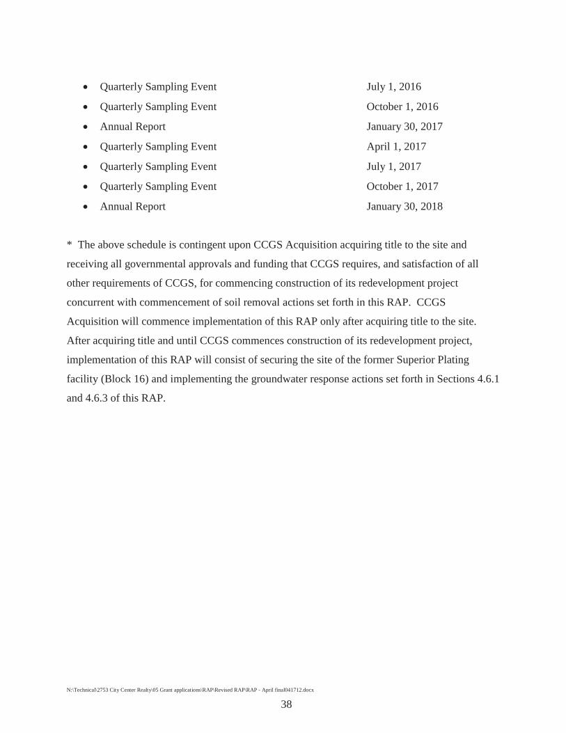
Quarterly Sampling Event July 1, 2016
Quarterly Sampling Event October 1, 2016
Annual Report January 30, 2017
Quarterly Sampling Event April 1, 2017
Quarterly Sampling Event July 1, 2017
Quarterly Sampling Event October 1, 2017
Annual Report January 30, 2018
* The above schedule is contingent upon CCGS Acquisition acquiring title to the site and
receiving all governmental approvals and funding that CCGS requires, and satisfaction of all
other requirements of CCGS, for commencing construction of its redevelopment project
concurrent with commencement of soil removal actions set forth in this RAP. CCGS
Acquisition will commence implementation of this RAP only after acquiring title to the site.
After acquiring title and until CCGS commences construction of its redevelopment project,
implementation of this RAP will consist of securing the site of the former Superior Plating
facility (Block 16) and implementing the groundwater response actions set forth in Sections 4.6.1
and 4.6.3 of this RAP.

N:\Technical\2753 City Center Realty\05 Grant applications\RAP\Revised RAP\RAP - April final041712.docx
39
9.0 References
Remedial Investigation Report, Subsurface Exploration Report. Superior Plating, Inc. Site, Minneapolis, MN. Soil Exploration Company: March 25, 1983.
Additional Subsurface Exploration for Chemical Contamination. Superior Plating, Inc. Soil Exploration Company: May 12, 1983.
Remedial Investigation, Subsurface Contamination Investigation. Superior Plating, Inc. Site, Minneapolis, MN. Soil Exploration Company: August 3, 1983.
Subsurface Contamination Investigation. Superior Plating, Inc. Soil Exploration Company: August 3, 1983.
Groundwater Investigation Work Plan. Superior Plating, Inc. Barr Engineering: February 24, 1984.
Specifications for Monitoring Well Installations. Superior Plating Site, Minneapolis, MN. Barr Engineering Co.: June 1984.
Uniform Hazardous Waste Manifest. Superior Plating, Inc. National Electric, Inc.: November 1, 1984.
Uniform Hazardous Waste Manifest. Superior Plating, Inc. National Electric, Inc.: June 19, 1985.
Remedial Investigation/Feasibility Study. Superior Plating, Inc., Minneapolis, MN. Barr Engineering Co.: August 1987.
Bidding Documents, Platteville Formation and St. Peter Sandstone Monitoring Well Installation. Superior Plating, Inc., Minneapolis Plating Site. Barr Engineering Co.: September 1988.
Remedial Investigation Report, Supplemental Investigation. Superior Plating, Inc., Minneapolis, MN. Barr Engineering Co.: January 1989.
Supplemental Investigation. Superior Plating, Inc. Barr Engineering: January 1, 1989.
Remedial Investigation Report, Supplemental Investigation. Superior Plating, Inc., Minneapolis, MN. Barr Engineering Co.: January 1989.

N:\Technical\2753 City Center Realty\05 Grant applications\RAP\Revised RAP\RAP - April final041712.docx
40
Remedial Design/Remedial Action Work Plan. Superior Plating, Inc. Barr Engineering Company: April 1, 1991.
Remedial Design/Remedial Action Work Plan Appendix C Attachment 6. Superior Plating, Inc. Barr Engineering: April 1, 1991.
Groundwater Pumpout System and Treatment Vault. Superior Plating, Inc. Barr Engineering: September 1, 1991.
Groundwater Pumpout System and Treatment Vault. Superior Plating, Inc. Barr Engineering Company: October 1991.
Preliminary Assessment/Visual Site Inspection, Final Report. Superior Plating, Inc., Minneapolis, MN. U.S. Environmental Protection Agency. PRC Environmental Management, Inc.: March 10, 1992.
Soils Remedial Investigation. Superior Plating, Inc. Barr Engineering Co.: September 1992.
1990-92 Groundwater Monitoring Report. Superior Plating, Inc. Barr Engineering: May 1, 1993.
QAPP. Superior Plating, Inc. Barr Engineering: September 1, 1993.
QAPP. Superior Plating, Inc. Barr Engineering: April 1, 1994.
1993 Groundwater Monitoring Report. Superior Plating, Inc. Barr Engineering: April 1, 1994.
Groundwater Remedial Action Evaluation Report. Superior Plating, Inc. Barr Engineering Company: July 1, 1994.
1995 Annual Monitoring Report. Superior Plating, Inc. Barr Engineering: April 1, 1996.
1996 Annual Monitoring Report. Superior Plating, Inc. Barr Engineering: April 1, 1997.
1998 Annual Report. Superior Plating, Inc. Barr Engineering: June 8, 1998.
1998 Annual Monitoring Report. Superior Plating, Inc. Barr Engineering: May 1, 1999.
1999 Annual Monitoring Report. Superior Plating, Inc. Barr Engineering: April 1, 2000.
2000 Annual Monitoring Report. Superior Plating, Inc. Barr Engineering: April 1, 2001.
2001 Annual Monitoring Report. Superior Plating, Inc. Barr Engineering: May 1, 2002.
2001 Annual Monitoring Report, Summary of Monitoring Results. Superior Plating Site. Barr Engineering Co.: May 2002.

N:\Technical\2753 City Center Realty\05 Grant applications\RAP\Revised RAP\RAP - April final041712.docx
41
2002-2003 Annual Monitoring Report, summary of Monitoring Results. Superior Plating Site, Minneapolis, MN. Barr Engineering Co.: August 2003.
2003-2004 Annual Monitoring Report, Summary of Monitoring Results. Superior Plating Site, Minneapolis, MN. Barr Engineering Co.: May 2004.
2004-2005 Annual Monitoring Report. Superior Plating, Inc. Barr Engineering: May 27, 2005.
2005-2006 Annual Monitoring Report Summary of Monitoring Results. Superior Plating Site, Minneapolis, MN. Barr Engineering Co.: May 1, 2006.
Phase I Environmental Site Assessment, Former Superior Plating, 315 1st Avenue NE, Minneapolis, Minnesota. Wenck Associates, Inc., December 2011.
Limited Phase II Investigation Work Plan, Former Superior Plating, 315 1st Avenue NE, Minneapolis, Minnesota. Wenck Associates, Inc., December 2011.

Figures

Engineers - ScientistsBusiness Professionalswww.wenck.com
Subject Property
CITY CENTER REALTY PARTNERS
Site Location Map
DEC 2011
Figure 11800 Pioneer Creek CenterMaple Plain, MN 55359-04291-800-472-2232
2,000 0 2,0001,000Feet
Minneapolis North 7.5 Minute Quadrangle (USGS: 1993)Minneapolis South 7.5 Minute Quadrangle (USGS: 1993)New Brighton 7.5 Minute Quadrangle (USGS: 1997)St. Paul West 7.5 Minute Quadrangle (USGS: 1993)
WenckPath: L:\2753\01\mxd\Site Location map.mxd
Area of Detail
HennepinCounty
DakotaCounty
AnokaCounty
RamseyCounty
ScottCounty
CarverCounty
Date: 12/16/2011Time: 9:59:30 AM User: ShuJC0243
CCGS ACQUISITION, LLC and CCGS FINANCE, LLC APR 2012

Engineers - ScientistsBusiness Professionalswww.wenck.com
Subject Property
4752
52
5th St NE
3rd St NE
4th St NE
4th St SE
4th St NE
CITY CENTER REALTY PARTNERS
Site Detail Map
DEC 2011
Figure 21800 Pioneer Creek CenterMaple Plain, MN 55359-04291-800-472-2232
150 0 15075Feet
2010 Aerial Photograph (Source: MN GEO)
WenckPath: L:\2753\01\mxd\Site Detail Map.mxdDate: 12/16/2011Time: 10:03:54 AM User: ShuJC0243
CCGS ACQUISITION, LLC and CCGS FINANCE, LLC APR 2012

Engineers - ScientistsBusiness Professionalswww.wenck.com
4
5
6
7A
3A
2A
18 15
11
1216
17 19
2nd St SE
4th St SE
Main St SE
1st Ave NE
E Hennepin Ave
Cent
ral A
ve S
E
5th St SE3r
d Av
e SE
University Ave SE
5th St NE
6th St SE
2nd
Ave
SE
3rd St NE
Cent
ral A
ve N
E
University Ave NE
4th A
ve S
E
6th St NE
8th St SE
Bank S
t SE
7th St NE
5th A
ve S
E2nd St NE
4th St NE
Prince St SE3r
d Av
e SE
2nd St SE
2nd
Ave
SE
7th St NE
CITY CENTER REALTY PARTNERS
Monitoring Well Locations
MAR 2012
Figure 31800 Pioneer Creek CenterMaple Plain, MN 55359-04291-800-472-2232
350 0 350175Feet
2010 Aerial Photograph (Source: MN GEO)
WenckPath: L:\2753\01\mxd\Monitoring Well Locations.mxdDate: 3/12/2012 Time: 1:46:54 PM User: ShuJC0243
LegendSubject Property
Approximate MonitoringWell Locations
CCGS ACQUISITION, LLC and CCGS FINANCE, LLC APR 2012

AP
R20
12

CIT
Y C
ENTE
R R
EALT
Y PA
RTN
ERS
Exca
vatio
n A
reas
FEB
201
2
Figu
re 2
Exc
avat
ion
Are
a C
Exc
avat
ion
Are
a D
Exc
avat
ion
Are
a E
Exc
avat
ion
Are
a B
Exc
avat
ion
Are
a A
Soi
l Man
agem
ent A
rea
1st A
ve N
E
5th St NE
University Ave NE
4th St NE
Engi
neer
s - S
cien
tists
Busi
ness
Pro
fess
iona
lsw
ww
.wen
ck.c
om
1800
Pio
neer
Cre
ek C
ente
rM
aple
Pla
in, M
N 5
5359
-042
91-
800-
472-
2232
Wen
ck
100
010
050
Feet
Path
: L:\2
753\
01\m
xd\E
xcav
atio
n A
reas
.mxd
Dat
e: 2
/22/
2012
Tim
e: 1
0:03
:31
AM
Use
r: S
huJC
0243
2010
Aer
ial P
hoto
grap
h (S
ourc
e: M
n G
EO)
Lege
nd Exca
vatio
n A
rea
Soil
Man
agem
ent A
rea
AP
R20
12C
CG
S A
CQ
UIS
ITIO
N, L
LC
and
CC
GS
FIN
AN
CE
, LL
C
����
���