cch70-3en
DESCRIPTION
CCH70-3enTRANSCRIPT


EDITION 3 (June 1996) (Annuls and replaces the Edition 2 of June 1979)
The present SPEClFlCATlON comprises :
lntroduction Page 3
6 indicative specimens of the QUALITY SHEET, 7 with its addition
5 technical specifications :
- for receiving GEgeneral requirements70-3 General 19
- forpenetrantPTdyeinspeotion 70-3 Penetrant Testing 29
- for particle 70-3magnetic MTinspection Magnetic Testing 37
- forultrasonicUTinspection 70-3 Ultrasonic Testing 43
- for RTradiographicinspection 70-3 Radiographic Testing 71
CDU - 669.14 : 621.224 / 620.1 (083.7) = 20
Reproduction in part or in whole prohibited
by : GROUPE CAHIER DES CHARGESEdited D'ETUDE HYDRAULIQUES
Address : Case Postale 3 - CH 1297 FOUNEX
Fax : +41 22 776 71 47
1


STEEL CASTINGS CCH 7013FOR HYDRAULIC MACHINES
INTRODUCTION
1 - PREAMBLE T 0 THE THIRD EDITION
Nov1971CCH 70-1 The first edition wasprepared on the initiativeofa STUDYGROUP (Groupe d’Etude) formed by several EuropeanDesigners and Founders.
June1979CCH70-2Thesecond edition took into account theaccumulatedexperiencesduring the first years of use.
1996 adapted:June CCH 70-3 The third edition is -to the actual principles of the QUALITY Organisation, -to the frequent practice of finishingthe parts in the shops of a firm other than the Designer, -to the latest developpments of nondestructive inspections.
THE STUDY GROUP is dwly constituted as “A non profit Organization” with articles of association. For this third edition, it gathers 3 Founders, 3 Designers, from Europe and North America and 1 Independent control organization as well as several technical cousultants.
2 - TERMINOLOGY 2.1 ASSOCIATES
Throughout this SPECIFICATION, only the following four designations willbe used to refer to the different parties involved.
CUSTOMER refers to the buyerhser ofthehydraulicmachineorhisrepresentative.
DESIGNER refers to the designer machine or representative.of the hydraulic his
FOUNDER refers to the party responsibleforthemetallurgicalrealizationofa Casting.
MANUFACTURER refers to the party performingthe various phasesof manufacturingleading to the completion of a component ofthe hydraulic machine or his representative.
Subject to technical or economic circumstances as well as contract conditions, the Manufacturer may be mistaken for either theDesigner or the Founder or yet a third party (FIRM) separate from either ofthe other two. It will be the responsibility ofthe issuer of Quality Sheets (QS) to clearly complete those sheets, so as to define without ambiguity the place of examination and consequentlythe state of advancement required forthe various controls prescribed.
2.2 TYPES OF MATERlkLS The present specification applies to Cast steels:
- Ferriticnonalloyedalloyedloworsteels - MartensiticresistantcorrosionCr-Ni-(Mo),steels
with martensitic transformation after annealing with 10 to 30% austenite (13-4, 17-4 for example)
- Austeno-ferritic (Duplex) corrosion resistant steels Cr-Ni-(Mo), without structural transformation: 35 to 65% austenite, 35 to 65% ferrite.
- Austenitic steelscorrosionresistantCr-Ni-(Mo), without structural transformation: 85 to 95% austenite, 5 to 15% ferrite.
3
CCH 70-3FOß HYDßAULlC MACHINES
2.3 QUALITY SHEETS
The Quality sheet (QS) is a document which contains all the arrangements relative to the technology and the control which are included in the agreement at time of placing an Order for a hydraulic component according to CCH 70-3.
3 - OBJECTIVE
The objective of this CCH 70-3 is to give an unequivocal definition of the technical and general supply conditions for Cast steel components used in hydraulic machines. It is therefore applicable for all items having at least one element in Cast steel and constituing one Part of a hydraulic machine.
T0 meet this objective, it defines especially all the inspection methods, the application procedures and the acceptance criteria to be considered during receiving inspections in the Foundry as well as in the Manufacturer’sworks.
Note : It is recommended that the Designer includes one copy of the CCH 70-3 in the technical file handed to the Powerplant upon delivery of the machine.
4 - COMMENTS ON QUALITY SHEETS
It is of great importance to distinguish the Quality sheets (W.) enclosed in this specification, (pages 7 to 18) identified as “SPECIMEN” and those Quality sheetswhich will be filled in by the Designer for each Casting considered to be important.
The first mentioned are only fictitious examples for illustration.
The indications given are in no way intended to serve as a rule, neither for the mechanical testing conditions nor for the choice of the non-destructive testing method to be applied.
The highly stressed areas are indicated by two concentric circles. Example: @ The Squares hatched or cross-hatched in blue, show different cases of inspection restriction which may occur:
The Squares with cross-hatched shading indicate that the type of inspection in question is very difficult or virtually impossible on the areas concerned because of limited-accessibility, incompatibility of shape and method or other reasons;
Squares with single hatched shading represent unusual inspections due to diverse circumstances.
Blank Squares show those cases where the inspectionsare feasible but considered not to be necessary for the Casting to be inspected.
The seconds mentioned specify the purchase conditions and acceptance standards; they have to be filled in by the Designer with a maximum of objectiveness with regard to the contract with his Customer. These forms will not only determine the Casting quality, but also influence the prices. Indeed, the quality level required involves adefinite manufacturing routine and Special precautions to be taken by the Founder, the Manufacturer or the Designer.
4

STEEL CASTINGS CCH 70-3FOR HYDRAULIC MACHINES
The Designer may have tlo produce several Quality Sheets (QS) for some complex items (welded assemblies). In this case each party will have to be aware of several Quality Sheets produced.
The Quality sheets should be part of:
- The Designer’s quotation to his Customer, - The Designer’s inqwiry to the Founder consulted and to the Manufacturer consulted, - The Designer’s Order to the Chosen Founder, - The Designer’s or the Founder’sOrder to the Manufacturer.
They will be legally valid in case of divergence with other documents. They particularly define:
- The authority or authorities responsible for reception, - The Standards used as a reference, - The specifications to be applied for verification of chemical composition and mechanical
properties, - The break down of the Casting into different areas, - The places where the different inspections have to be carried out, - The surface quality required for eacharea of the Casting, - The non-destructive testing method to be applied for checking the soundness of each Casting area,
as well as the extent of the inspection (e.g. 100% inspection or spot checking), - The acceptance critleria for the required inspections - Specific requirements for certain manufacturing and inspection Operations.
No other inspections exceeding those defined may be required without mutual agreement of the interested parties. If complementary inspections are decided by such an agreement they will only have an informative value or will be the subjeet of an amendement to the Order.
If a given area should be inspected by Spot checking only, the conditions will be defined after agreement between the parties.
If a confirmative radiographic inspection is forseen, radiography will only be carried out in case the results obtained by ultrasonics do not conform with the specified criteria and thus do not permit an evaluation of the acceptability of the indication. The decision to repair or to perform a radiographic inspection for confirmation is left to the Founder ( see technical specification UT 70-3).
The non destructive inspections requiered by the Quality Sheet (QS) as having to be carried out by the Manufacturer or Designer on the finished part, engage the responsibility of the Founder; thus informed about the Designer’s inteintions and backed by his experience, the Founder will take the necessary measures to avoid -as mwch as possible - any possible failure of his supply in this subsequent state, by having recourse to manufacturing precautionary measures and to preliminary inspections corresponding to the Designer’s requirements (see technical specification GE 70-3).
5

I STEEL CASTINGS I CCH 7013FOR HYDRAULIC MACHINES
5 - CORRELATION BETWEEN THE QUALITY SHEET AND THE TECHNICAL INSPECTION SPEClFlCATlONS
The requirements to be specified by the Designer in the Quality Sheet (QS) are identified by the Symbol in the right hand margin of the various paragraphs defining the requirements (GE, PT, MT, UT, RT). These requirements will be indicated as well in the check-list in the back of the Quality Sheet(QS) or appended to the Quality Sheet (QS).
6

I QUALITY SHeET Nr QS - 0010 I CCH 70-3
Power plant SALTO GRANDE Quantityanddesignation 3 PELTON RUNNERs Drawings Nr 68981 and 4803 Casting)weight(finishedUnitaly 19.00 kg
lnquiry Nr 3542 dated 18.11.95Custorner / Country <<V>>
Designer <<X>> Nr Order 12071I dated 15-02S + <<X>>Founder <<Y>> at lnspection F's works by <<V>> (b)
byManufacturer <<ZN at lnspection M'sworks <<V>> (b)
CHARACTERISTICS OF MATERIAL Designation: 4;- X5 Cr Ni 13.4 AccordingtoStandard : analogic DIN 17445
0-3§ji A2B2 C1 A2 B2 C2 43 B2 C2 *
SKETCHMEFIMG THE areas the for dimensionReference : 720 rnrn
;)
3) See Sketch Established by I Checked I Approuved I "Designer"by by J) F=Founder M=Manufacturer I I I
I -I..rlal IU
See back A) According to spec. CCH 70-3 signed I I I
I I5 ) Delete where not applicable I
I) See Casting's drawing Dated 7

ADDITIONS T 0 QUALITY SHEET I I
MECHANICAL TESTS at the FOUNDER’S WORKS, according to GE 70-3, 0 2.2 (*) = Deletewhere not applicable
cccast-onw test-coupons. (+)
Numberoftest-Coupons :(+) 121 per Casting, EI= to bei.e. : retest. testedfor and
Position and dimensions of the test-Coupons are given by the Designer, either on the drawing or on the sketch of the Q.S. If nothing has been specified, the choice will be left to the Founder.
removal, the stamped identifiedtheBefore test-Coupons will be and by Founder theinpresence of : dh andlor
Stressrelieving heat treatment :(Ir) - withtest-Couponsreattachedonthe Castings.
Test Each giveshall specimen(s)specimens : test-Coupon I 1 I tension-test and-I 2 X 31 impact-testspecimens.
Standard(s) : Nr DIN 501 15, DIN 50125
CHECK-LIST of other requirements from DESIGNER, AnnexChapter 0 according to the symbols in margin (see Introduction,Q 5) Nr Page
GE 1.4 GE 1.5
GE 2.1 GE 2.2.1.3
GE 3.1
GE 3.3 GE 3.4 GE 4.1 GE 5.1.2.1 GE 5.1.2.2 GE 5.1.3
GE 5.1.4
GE 5.2.3 GE 5.3.3
GE 7.2 PT 3 MT 3.1.2 MT 4.3 MT 7.2 UT
UT I 0.2
1.2 I Methodtobeuse : M o r AVG. (+) - -UT 1.3.2 UT 1.3.4 UT 1.4.2 UT 1.9
UT 2.2
UT 2.4.2 RT 2
RT 10.1 RT 10.3 RT
GE 11.2 2.2.1 I Rp0,2 I Rm < 0,85
1 I -
I -
8 2 / 5I
I QUALITÄTS-VORSCHRIFTENBLATT Nr QS - 0020 I CCH 70-3
Anlage SCHWARZSEEBezeichnung und Anzahl
Nr Zeichnungen 258745 Einzel-Fettiggewicht
Kunde / Land <<V>> Konstrukteur <<X>>
Bezugsdurchmesser= 1.OOO
(*) für DurchstraAb--\ U
ErstelltdurchGeprüftdurchdurchGenehmigt"Konstrukteur"
;) Siehe Rückseite j) Gemäss Spezif. CCH 70-3 ?) Nichtzutreffendes streichen
.X X X X X>> ) Siehe Zeichnung Datum 9

ERGANZUNGEN ZUM CCH 7013QUALITÄTS-VORSCHRIFTENBLATT Nr. QS- 0020 ~
AnzahlderProbeleisten :(Ir) I 3 I per Stück,
m m davon : 121 zu prüfen und Erzatzproben.für
Lage und Dimension der Probeleisten werden durch den Konstrukteur bestimmt, entweder auf der Zeichnung oder auf der Skizze c<Zoneneinteilung>,des Qualitäts-Vorschriftenblattes. Ist dies nicht der Fall, so entscheidet der Giesser.
Vorder Probeentnahme : die Probeleisten werden durch den Giesser angestempelt und identifiziert inAnwesenheit von : rW>> (für .V>>)
Spannungsarmglühen :(+) - zum Spannungsarmglühen werden die Probeleisten ans Gussstück angeheftet. - das Spannungsarmglühen der Probeleisten erfolgt simuliert.
Probestücke: Jede Probeleiste muss I 7 I Zugprobe(n) und
Norm(en) : N r. Kerbschlagproben ergeben.
Kapitel 9 CHECKLISTE der anderenAnweisungen
gemässRand-Symbole(sieheEinfürung, vom KONSTRUKTEUR, Anhang
9 5) Nr Seite
GE 1.4 GE 1.5 GE 2.1 GE 2.2.1.3 GE 3.1 GE 3.3 GE 3.4 GE 4.1 3 GE 5.1.2.1 GE 5.1.2.2 GE 5.1.3 GE 5.1.4 GE 5.2.3 GE 5.3.3 GE 7.2 3 PT 3 MT 3.1.2 MT 4.3 MT 7.2 UT 0.2 UT 1.2 UT 1.3.2 UT 1.3.4 UT 1.4.2 UT 1.9 UT 2.2 UT 2.4.2 RT 2 RT 10.1 RT 10.3

I QUALITY SHElET Nr QS - 0030 I CCH 70-3
Power plant VlNH SON Quantityanddesignation 2 -1 TuRB. RUNNERs Unitary 1 9 . m kgweight(finishedDrawings Nr 41 713 B Casting)
Customer / Country <<V>> Nr lnquiry 3542 da td 18.11.95
Designer <<X>> Nr Order 120711 dated 15.02.96 at byFounder << Y>> lnspection F's works *W>>+ <<X>> (b)
= at by + <<X>> (b)Manufacturer <<Y>> lnspection M'sworks <<W>>
CHARACTERISTICSOF MATERIAL Designation : G - X5 Cr Ni 13.4 AccordingtoStandard : analogic DIN 17445
The Designer's requirements are indicated in the table below by X (or by QL, QP, SL accordi R9 N8 N10 N8
mP3 P3 P3
I A ~BZ c 2 A2 B2 C2 -
SKETCH Reference forthedimensionareas : 950 mm
reference diarneter = 1,000 -+ (*) for radiography (rnm)
a) See sketch Name Established Approwed byby Checkedby "Designer" b) F=Founder M=Manufacturer
andC) See back d) According to spec. CCH 70-3 <<X X X X X>> e) Delete where not applicable f ) See Casting's drawing Dated
X
I ADDITIONS T 0 QUALITYSHEET Nr QS-0030 I CCH 7013 MECHANICAL TESTS at the FOUNDER’S WORKS, according to GE 70-3,5 2.2 (+) = Delete where not applicable
tccast-on,, test-coupons. (+)
Number of test-Coupons :(+) 1 2 I per Casting, -fori.e. : to be tested and T I retest.
Position and dimensions of the test-Coupons are given by the Designer, either on the drawing or on the sketch of the Q.S. If nothing has been specified, the choice will be left to the Founder.
removal, the test-Coupons and identified by the Founder Before will be stamped ofin the presence : NY>>andlor <<X>>
Stressrelievingheattreatment : (+) - with test-Coupons reattached on the Castings.
Testspecimens : Eachtest-Couponshallgive 111 tension-test specimen(s) and
131 impact-test specimens.
Standard(s) : Nr
12

QUALITÄTS-VORSCHRIFTENBLATT Nr QS/WA I CCH 70-3 I Anlage $EAVERDAMBezeichnung und Anzahl
Zeichnungen Nr 87.625.750 B Einzel-Fertiggewicht
Kunde / Land <<V>>
) Nichtzutreffendes streichen
3
I ERGANZUNGEN ZUM I CCH 7013 QUALITÄTS-VORSCHRIFTENBLATT Nr. QS/0040A MECHANISCHEWERKSTOFFPRüFUNGBEIMGIESSERgemässGE70-3, § 2.2 (*) = NichtAnwendbaresdurchstreichen
((Angegossenen+>Probeleisten(*)
AnzahlderProbeleisten : (*) I 4 I per Stück,
U-davon : 12] zu prüfen und 121 fürErzatzproben.
Lage und Dimension der Probeleisten werden durch den Konstrukteur bestimmt, entweder auf der Zeichnung oder auf der Skizze (CZoneneinteilung,, des Qualitäts-Vorschriftenblattes. Ist dies nicht der Fall, so entscheidet der Giesser.
Vor der Probeentnahme : die Probeleisten werden durch den Giesser angestempelt und identifiziert in Anwesenheit von : <<V. + <<X>>
Spannungsarmglühen :(1-) - zum Spannungsarmglühen werden die Probeleisten ans Gussstück angeheftet. - das Spannungsarmglühen der Probeleisten erfolgt simuliert.
Probestücke :
Norm(en) :
Jede Probeleiste muss
N r. ASTM A 370
I I
7 3
I I
Zugprobe(n) und
Kerbschlagproben ergeben.
Kapitel 9
GE 1.4 GE 1.5 GE 2.1
2.2.1.3 GE GE 3.1 GE 3.3 GE 3.4
4.1 GE GE 5.1.2.1
5.1.2.2 GE 5.1.3 GE 5.1.4 GE 5.2.3 GE 5.3.3 GE 7.2 GE
PT 3 MT 3.1.2 MT 4.3 MT 7.2
0.2 UT 1.2 UT 1.3.2 UT
UT 1.3.4 1.4.2 UT
UT 1.9 2.2 UT 2.4.2 UT
RT 2 RT 10.1 RT 10.3
2 1 3 14
FICHE QUALITE NS FQ-96-0050 I CCH 70-3 I
pour le detail des 2 elementsA et B
voir Fiche Qualite NoFQ - 96 - W51
i
9)Voir scherna Nom Etablis par ContrGIB par Approuv6 par "Constructeur" 3) F= Fondeur R= Realisateur et3) Voir au verso d) Selon specif. CCH 70-3 ccx X X X X,, e) Biffer la rnention inutile f) Voir plan de la piece Date 5
I COMPLEMENTSA LA FICHE QUALITE NO FQ - 96- 0050 I CCH 70=3 ESSAIS MECANIQUES chez le FONDEUR, selon GE 70-3, 3 2.2 (*) = biffer les mentionsnon-retenues
/Appendices d’essaiscccoules attenantsn. (*)
Nombre d’appendices d’essais.(*)
pour contre-essais
Avant-prelevement,
Norme(s) :/ No
Zhapitre 5 CHECK-LIST desautresprescriptions
selonlesmentionsenmarge(voirIntroduction, du CONSTRUCTEUR,
Q 5) Annexe
No Page
GE GE
GE GE GE GE GE
GE
GE GE GE
GE GE GE GE PT MT
MT MT
UT UT
UT UT UT
UT 1.9 Contr6lessupplementaireseventuels sur reparations <<majeures,>. - -UT 2.2 Methode a utiliser CAD ou M.(*) UT 2.4.2 Autres limites que celles proposees par fig. 7 a 11. RT 2Autreprocedureparticuliere, Si imposee. RT 10.1 Type d’lQI, Si impose. RT 10.3Dureed’archivagedesfilms.
16

FICHE QUALITE NQ F Q - 9 6 - 0 0 5 1 A I CCH 70-3 I Nombre ELEMENTS pour 19 CORPS D'INJECTEUR Centrale SAYNT-GERMAIN objet et
NPPlans H - 27342A unitaireMasse (pike finie) A = 3 W , 6 ~ 3 1 0 kg
Client I Pays <<V>> doffreDemande NQ D 0 7025 du 28-04-96 Constructeur du <<X>> NQ Commande
de dimensionnantzones : 660 mmSCHEMA DE~DEFINITIONDES ZONES\ \ Coter6f6rence les \ ( * ) = apres chanfrein
1=3xt ~
I
Element A Element B I
I) Voir Schema Nom Etablis par Contr6l6 par Approuv6 par 'Constructeur" 1) F= Fondeur R= Realisateur :) Voir au verso et
1) Selon specif. CCH 70-3 'Ignature .X X X X XN I I
1) Biffer la mention inutile I
) Voir plan de la piece Date I7

COMPLEMENTS A LA FICHE QUALITE NOFQ - 96 - 0057 A I CCH 70=3 I ESSAIS MECANIQUES chez le FONDEUR, selon GE 70-3, 9 2.2 (*) = bifferles non-retenuesmentions
Lingots-echantillons~coules separementx (*)
Nombre d’essais. (*) EI-..d’appendices
[31 par lot de pieces issues d’une mQme coulee
121 pour etsoit : essais 111 pour contre-essais
Position et dimensions des appendices d’essais sont fixes par le Constructeur, soit sur le plan soit sur le Schema de la F.Q. Si tel n’est pas le cas, elles sont laisseesa I’initiative du Fondeur
Avant-prelevement, lesappendicesd’essaisseront poinGonneset identifiesparle Fondeur, en presence : ((W>>(pour .V>>)de
, . I . , . ..Detensionnement :(*) -N - <<detentionnementsimule,, des appendices.
appendicetiprouvettes : Chaque d’essais doit donner 1 2 1 eProuvette(s) de traction et
131 eprouvette de resilience.
N ONorme(s) : A370 ASTM
;hapitre 5 Page
1.4 GE 3 1.5 GE 2.1 GE
2.2.1.3GE
3.1 GE 3.3 GE 3.4 GE
4.1 GE
5.1.2.1GE 5.1.2.2GE
5.1.3 GE 5.1.4 GE
5.2.3 GE 5.3.3 GE 7.2 GE 3
PT 3 MT 3.1.2 MT 4.3 MT 7.2
UT 0.2 1.2 UT 1.3.2 UT 1.3.4 UT
UT 1.4.2 1.9 UT
2.2 UT UT 2.4.2 RT 2 RT 10.1 RT 10.3 UT 1.7 UT 2.7.1
2 /3

I STEEL CASTINGS I GE 7013FOR HYDRAULIC MACHINES
GENERAL TECHNICAL RECElVlNG SPEClFlCATlON
This specification contains the following chapters:
1 - GENERALREQUIREMENTS 4 - DIMENSIONALINSPECTIONS
1 .I Preamble 4.1 At delivery Stage by the Founder 1.2Personnel and equipment of the Founder 4.2At delivery Stage by the Manufacturer
and (or) theManufacturer. 1.3Steel melting 1.4Heat treatments 5 - ELIMINATIONOFDEFECTS 1.5 Reception
5.1 General considerations 2 - MATERIALINSPECTIONS 5.2 Defects revealed at the Foundry
5.3 Defects revealed at the Manufacturer or 2.1 Chemical composition Designer’sworks 2.2 Mechanical properties 5.4Defects revealed at the Customer’s
Powerplant.
3 - NON-DESTRUCTIVEINSPECTIONS 6 - NON-CONFORMlTlES
3.1 Visual inspection 3.2Soundness Checks:
- by dye penetrant inspection 7 - GUARANTEE. - by magnetic particle inspection - by ultra$onic inspection - by radiagraphic inspection
3.3Water tightness under pressure test. 3.4Runner balancing
1 - GENERALREQUIREMENTS
1.1 PREAMBLE
In case of disagreement between the Customer, Designer, Manufacturerand Founder on the choice of inspection means to be used, their application, or in the interpretation of the results obtained, the Designer’s ruling shall have precedence because of his own commitments.
1.2 PERSONNEL AND BQUIPMENT OF THE FOUNDER AND (OR) MANUFACTURER.
The Founder and/or the Manufacturer will have a written Quality Assurance Program based on the requirements of ISO 9002. If the program hasn’t been certified by an accredited organization, theDesigner will verify that the program meets his own criteria.
The Designer will make Sure, based on the evaluation procedure of his suppliers that theyare able to manufacture the parts in question.
19

I STEEL CASTlNGS I GE 7013FOR HYDRAULlC MACHINES
1.3STEELMELTING
Normally the steel used should be elaborated in an electrical furnace. Retreating by supplementary metallurgical methods :A.O.D., V.O.D., A.P.C (*) can be accomplished so as to obtain better welding capabilities, high impact strength values and improvement in the soundness ofthe Parts.
(*) AOD: Argon OxygenDecarburization VOD: Vacum Oxygen Decarburization APC : Ladle refining (Affinage Poche Chauffante)
1.4 HEATTREATMENTS
The conditions for the Performance of the heat treatments, Position of the part in the furnace, number and Position of the thermocouples will be defined by the Founder and/or the Manufacturer. They will be communicated to the Designer should he request it.
1.4.1 Quality heat treatment.
The choice of the appropriate quality heat treatment Parameters determining the mechanical properties will be left to the Founder. They must conform to the existing Standards and/or the specific requirements of the contract.
1.4.2 Stress relieving heat treatment
After welding a Stress relieving treatment is to be carried out except in Special cases (See Paragraph 5). It’s cycle will be in conformity with the welding process qualifications and procurement specifications. The Founder or the Manufacturer will have to obtain the agreement of the Designer on the conditions of this heat treatment.
1.4.3 Heat treatments documentation
All the thermal cycles applied will be recorded and the diagrams will be kept at the disposal of the Designer at the Founder’s or at the Manufacturer’sworks. A Summary of the cycles performed will be described either on the mechanical properties certificate or On a heat treatment certificate (heating and cooling rate, holding temperature with maxi deviations, holding time ).
1.5RECEPTION.
The reception inspections to be carried out by the Founder and/or the Manufacturer are defined by the Quality Sheet; they may comprise checking of the chemical composition and the mechanical properties, (at the Founder only) as well as the non destructive inspections. These tests are carried out by the Founder and/or the Manufacturer in the presence of theDesigner and/or the Customer if specified in the Order. In this case the Founder and/or the Manufacturer will inform the Designer in writing as specified in the Order.
The Designer shall inform the Founder and/or the Manufacturer of the date of his arrival and/or of the arrival of his Customer at the Founder’s or the Manufacturer’sworks.
At time of final reception, the contractual documents of manufacturing and inspections will be put at the disposal of the Designer or his representative.
20

I STEEL CASTINGS I GE 7013FOR HYDRAULIC MACHINES
2 - MATERIAL INSPECTIONS
2.1 CHECKING OF THE CHEMICAL COMPOSITION
The chemical composition of the heat will be checked by the Founder and indicated on the certificates. A check-analysis on the Casting may exceptionally be taken into consideration if agreed by the parties. The steel grade has to be clearly defined in the inquiry to the Founder. The Founder will state in his offer the chemical composition of the material to be supplied and the Designer will mention it in his Order and in the Quality Sheet.
Generally the followling values are recommended for sulphur and phosphoruscontents:
For unalloyed or slightly alloyed steels: S10.030%P10.030%
For martensitic alloyed steels 13-4 without specified minimum molybdenum content, the Designer may impose more restrictive values for sulphur and phosphorus than those indicated in the Standard:
S10.015%P10.025% but S + P1 0.030% Si 1 0.50%
2.2 VERlFlCATlON OF MECHANICAL PROPERTIES
2.2.1 lmposedvalues The values of the mechanical properties will be indicated in the Quality Sheet. Generally the tests will check for the following mechanical properties:
1 -Tensile test : -Tensile Strength : MPaRm in -Yield sltress : MPa in 0.2 Rp -Elongation (5d) : A5 in % -Reduction area : Z i n %in
2 - Impact test at the temperature required by the Quality Sheet : - Impact instrength : CVN or CUN J (Joules)
(Charpy V Notch or Charpy U Notch)
3 - Hardness test if required - Numkr and Position of check Points.
The number of test specimens required is always meant per Casting (not per heat). In case a Serie of pieces is Cast from the Same heat, the necessary number of tests per lot will be fixed by the Designer and if required the verification of hardness per Casting to control the homogenity of the lot in question.
2.2.2Testingconditions
The tests will be carried out on test specimens Cut from cast-on test Coupons remaining attached to the Casting throughout the qwality heat treatment. Whenever technical reasons require that the test-Coupons are removed before the quality heat treatment, they will be detached and subsequently reattachedto the Casting in the presence of or in algreement with the Designer and/or the Customer before quality heat treatment. The test-Coupons will be cut-Off after quality heat treatment eventually before rough machining,in the presence or after the agreement ofthe Designer and/or of theCustomer.
21

I STEEL CASTINGS I GE 7013FOR HYDßAULlC MACHINES
The Designer may request: - either the presence of test-Coupons on the part during the Stress relieving heat treatment; these Coupons will have been removed and stamped by the Designer or the Customer before rough machining and then re-attached to the Casting by the Founder.
- or a simulated Stress relieving.
If, for technical reasons, the test-Coupons cannot be Cast On, separately Cast test blocks may be used if previously approved by theDesigner and/or Customer.
2.2.3 Number and Position of the test Coupons The number, Position and dimensions of the test-Couponswill be determined by common agreement between the Designer and the Founder and will be indicated on the Quality Sheet. The Founder will provide supplementary test Coupons necessary for his internal tests.
2.2.4 Testing installations and personnel All necessary tests will be carried out by the personnel of the Founder’s inspection department, using the testing equipment available at the Foundry. The test equipment shall be calibrated periodically. The calibration reports shall be placed at the Designer’s and the Customer’sdisposal. No Special calibration will be carried out.
3 - NON DESTRUCTIVE INSPECTIONS
The nature of the non destructive inspections as well as the areas to which the various examinations apply, must be clearly defined on the Quality Sheet attached to the inquiry and the Order addressed to the Founder and/or the Manufacturer.
The non destructive inspections will be performed exclusively by qualified and certified personnel in conformity with Standard EN 473 or a recognized equivalent System (example : SNT TC 1A or ISO 9712).
The qualification procedures, the qualification levels of the Operators and their maintenance, shall be described in the Quality Assurance program of the Founder and/or Manufacturer. If the Founder and/or the Manufacturer does not have such procedures whichare accepted by the Designer, he will provide other inspectors certified and recognized by the Designer.
3.1 VISUAL INSPECTION
Non destructive testing will be preceded by a visual inspection. The visual inspection will Cover the entire Casting under the following aspects:
1 - Identification, 2 - Surface quality, 3 - Visible defects, 4 - Conformity to the documents of the Order.
This visual inspection may be carried out with reference to a specification as, for instance, technical recommendation BNlF 359.01 of the “Bureau de Normalisation des lndustries de la Fonderie” (Foundry Industry’s Standardization Office)or ASTM A802 for the surface quality andMSS-SP 55 specification for visible defects or any other specification indicated on the Quality Sheet.
For the surface roughness of machined or fine groundareas, it is recommended to use the designations N1 to N11 of the ISO 2632 document which is referred to in numerous Standards.
Dimensional aspects should be verified in accordance with the criteria described in Paragraph 4.
22

STEEL CASTINGS GE 7013FOR HYDRAULIC MACHINES
3.2 SOUNDNESS CHEaKS
3.2.1Operating conditiansandspecifications The Operating conditions and acceptance classes are described in the following procedures:
PT 70-3Technical Specification for dyepenetrantinspection, MT 70-3 Technical Specification for magnetic particle inspection, UT 70-3 Bchnical Specification for ultrasonic inspection, RT 70-3 Bchnical Specification for radiographic inspection.
3.2.2 Choice of inspection methods The choice of inspection lmethods and of the acceptance classes should be afunction of the working conditions under which the Casting will operate, considering its hydraulic design and its Service conditions (erosion, cavitation, shock loading, fatigue, working Stresses of the different areas, etc.). It is the Designer who makes these choices.
3.3PRESSURETEST
The parts subjected to pressure are submitted to a test after finishing in the Manufacturer’sor Designer’s works or at site. The De$igner must specify on his drawing the exact information about the testing conditions (type of fluid, pressure, test duration), in such a waythat the Founder may manufacture the Casting in full knowledge of the responsibilities in question.
3.4RUNNERBALANCIMG
The static balancing is the Standard procedure. T0 perform the runner balancing, theDesigner must indicate the procedure, the Standard to be used and the maximum acceptable imbalance in Kgm, as well as the sensitivity of the method to be used. The Designer shall indicate by which means and where the non acceptable imbalance will be eliminated or compensated.
4 - DIMENSIONAL INSPECTIONS
4.1 AT DELIVERY STAGE BY THE FOUNDER
The dimensional inspection conditions and the tolerances to be achieved by the Founder will be determined by the Designer in his inquiry. Due to the complexity of dimensional tolerances conditioned by the hydraulic shape of the Castings it i$ extremely difficult to establish general rules. Thus, in his offer, the Founder will accept or discuss the required tolerances.
It should be pointed out tthat tolerances have a direct influence on the price of the Casting.
4.2 AT THE DELIVERY $TAGE BY THE MANUFACTURER
As far as the surface conitinuity Profiles areconcerned (ondulations) and the hydraulic dimensions which are not covered by the CE1 r@commendations (CE1 = Commission Electrotechnique Internationale, last edition for hydraulic turbines and Storage Pumps), the Designer will be the only judge concerning the acceptability of dimensional deviations and will evaluate their consequences on the working Performance he guarantees.
23

STEEL CASTINGS I GE 70-3 IFOR HYDRAULIC MACHINES
5 - ELIMINATION OFDEFECTS
5.1 GENERAL CONSIDERATIONS
5.1.1 Classification of defects based on their origin. Rules for assumptionof costs of repairs.
1 - Defects for which the Founder is responsible are defects of metallurgical origin or defects resulting from the Founders manufacturing Technique.
2 - Defects for which the Manufacturer is responsible are those resulting from the manufacturing of the product in the works.
3 - Defects for which theDesigner is responsible are those resulting from the design and the dimensioning of the Casting.
4 - Possible defects for which the Customer is responsible would be those caused by exploitation conditions exceeding the guarantee given by the Designer, as well as for defects resulting from wear due to abrasion of material due to the quality of the water used.
As a rule, both the Founder and the Manufacturer or the Designer are liable for the repair of defects for which they are responsible, i.e. for defects exceeding the acceptance criteria required by the Quality Sheet and discovered by one of the inspection methods prescribed in the Same Quality Sheet or by simple visual inspection.
5.1.2 Classification of defects based on their dimensions and onthe degree of Stress in the area considered.
1 - Dimensions Excavations are considered “ MAJOR” when either of the following criteria (maximum depth /surFace) are exceeded. In the absence of specific instructions issued by the Designer in his Quality Sheet, the following criteria are applicable:
Reference dimension I 1 000 > 1000 > 2000 > 4000 units (according to Quality Sheet) I2000 I4000
(in mm)
Depth : in % of local thickness 40 35 30 25 %
but limited to: 10 15 20 25 mm
Surface 40 65 100 160 Cm2
24

I STEEL CASTINGS I GE 7013FOR HYDRAULIC MACHINES
2 - Degree of stress level
The highly stressed areas will be indicated on the Quality Sheet by two concentric circles.
5.1.3Welding preparatian (excavations) Before repair by welding, the defects have to be completely removed until the disappearance of any indication above class 1 of PT 70-3 or of MT 70-3. This principle is applicable for excavations corresponding to 1/3 of the thickness with a maximum of 30 mm. Beyond this depth , class 3 in PT or class 2 in MT is applicable.
For certain highly stressed areas the Designer may specify more severe criteria.
5.1.4 Criteria of acceptance for repair welding Unless otherwise stipulated in the Order, the repaired areas will be inspected by the Same methods and acceptance criteria as inittially required for the area in question.
5.1.5 Waiving of repair by welding The Designer may accept at any time, on his own responsibility , that certain excavations are not built up by welding, provided that no' defects exceeding the acceptance criteria are left on the Casting, and if the presence of the excavation does not interfere with an unobjectionable functioning of the Casting.
5.2DEFECTSREVEALED AT THE FOUNDRY
5.2.1 Repair by welding Defects discovered during manufacturing in the Foundry will be excavated and repaired by welding.
5.2.2 Report of areas to be repaired The dimensions and Positions of major excavations exceedingthe acceptance limit (as Set by 5.1.2.1) as well as those in highly stressed areas (5.1.2.2) will be reported and if required completed by photos. This report will be submitted to the Designer.
5.2.3Weldingapproval The Designer will specify on the Quality Sheetthe excavations which must be submitted to him for approval before repair of defects (for example major excavations or excavationslocated in highly stressed areas).
1 - The welding procedure will be qualified. Any existing certified qualifications corresponding to the criteria defined will not be renewed.
2 - Welders and Operators will be qualified. 3 - The welding procedure and if needed the welding procedure homolagation, as well as the
welders qualifications, must be submitted to the Designer for approval prior to the starting of the repair work.
4 - The Designer will grant his welding approval onthe basis of the list of areas to be repaired (5.2.2) as well a$ on the basis of the PT and MT inspection reports issued as result of the excavations (5.1.3).
5.2.4Stressrelieving A furnace stress relieving treatmentwill be carried out after welding. This heat treatment may only be omitted with the agreement of theDesigner (See 1.4.2).
25

STEEL CASTINGS GE 70-3FOR HYDßAULlC MACHINES
5.3 DEFECTS REVEALED AT THE MANUFACTURER’SOR THE DESIGNER’S WORKS If the Designer decides for weld repairs on defects appearing during machining they will be performed under the following conditions.
5.3.1 Welding repairs with imposed stress relieving Major repairs in the sense of § 5.1.2.1 and/or minor repairs in stressed areas (5.1.2.2) which require subsequent stress relief. These repairs are executed by the Founder and are recorded. They may be undertaken by theManufacturer or the Designer (after the approval of the Founder) in accordance with the agreed and qualified welding procedure.
5.3.2 Welding repairs without stress relieving Located in less stressed areas repairs may be made by the Manufacturer or the Designer (after advising the Founder), subject to the agreed and qualified procedure.
5.3.3 Repartition of costs of repair It is recommended to lay down in writing, after mutual agreement andbefore placing an Order, the repartition of costs of repairs of possible arising repairs. If such measures have not been taken, the repartition of costs should be fixed by a mutual agreement between the Founder, the Manufacturer and the Designer prior to the commencement of work. The repartition of repair costs may, for instance, be fixed on the basis of one of the criteria mentioned hereafter:
- Surface inspection (dye penetrant, magnetic particle), - Volume and number of excavations, - Based on the selling price of the Casting.
5.4 DEFECTS REVEALED AT THE CUSTOMER’S POWERPLANT
5.4.1Warantywork During the period of guarantee, repairs will be carried out by theFounder, the Manufacturer or the Designer. The costs will be spread in accordance with 5.1.1 and 5.3.3.
5.4.2 Repair beyond the warranty period After the warranty period, repairs may be executed under the Customer’s responsibility with the prior advise given to the Designer. The Designer may advise the Founder for information purposes. The Customer will assume the cost of repairs.
6 - NON CONFORMITIES
The Founder or the Manufacturer will rapidly inform the Designer of any deviation found. The Designer decides to either:
- accept in present states, - repair and use the part, - scrap the part.
Subject to the conditions of his contract, the Designer will advise theCustomer of the decisions taken or will by agreement with the latter, find an acceptable solution.
Acceptance of a non conformity by the Customer in no way discharges theFounder, the Manufacturer or the Designer from their respective responsibilities.
26

I STEEL CASTINGS I GE 7013FOR HYDRAULIC MACHINES
7 - GUARANTEE
7.1 Within the limits specified in 5 5, the present guarantee Covers all deviations susceptible to interfere with the proper operatian of the component considered, or to impair the security of the machine.
This guarantee englages the Designer, Manufacturerand Founder to carry out all necessary repairsas soon as possible, by appropriate professional techniques defined by the CCH 70-3 and procedures, and to ensure that the state of the repaired Casting meets the original specifications or, if such specifications have not been established to meet the professional Standard.
7.2 As the guarantee conditions of the Founder and Manufacturer are closely connected with the Designer’sguaranlee to his Customer for the hydraulic machine to be delivered, the Designer is obliged to inform the Founder and the Manufacturer before passing an Order about his own engagements for the supply in question. The Designer will not be allowed to impose more severe conditions to the Founder and the Manufacturer than the ones he has accepted himself.
7.3 Contracts to which the present Specification for lnspection is applied are of mutual interest to the Founder, Designerand the Manufacturer and it will be essential to work in a sense of close cooperation to assure the required guarantee given.
7.4 The period of guarantee for theFounder and Manufacturer will be the Same as that of the Designer. Usually, contracts fkx hydraulic machines require a guarantee covering a certainperiod of exploitation, after provisional reception of the installation, i.e. expressed in thousands of hours or in months, with a reasonable temporal limitation from a date, fixed in the contract between the Designer and the Customer. Considering the diuersity of cases and types of exploitation, the duration of the guarantee must be subject to commercial negotiations between the Customer and the Designer for each Order.
7.5 Any request for application of the guarantee should be transmitted by the speediest means of communication as soon as a deviation has been discovered and subsequentlyconfirmed in writing. On this occasion, any useful information should be transmitted to the party concerned.
-Nature of the defect -Means by which it was detected -Location -Geometrie dimensions of the defect (if possible with dimensioned sketch and photographs).
The party concerned by a request for application of the guarantee will as soon as possible propose an adequate repair procedure, execute the repairs and, in case of need, furnish the necessary pieces. It goes without saying that the party ensuring the guarantee reservesthe right to view that the deviation occurred.
No repair will be effected without the agreement of the party considered responsible and only repairs which meet the instructions of this party will be carried out. Any infringement of this regulation will lead to an annulment of any responsibility for the other party.
7.6 The validity of the guarantee is always subjectto the Operating and maintenance instructions specified by the Designer, and agreed by theCustomer.
27


I STEEL CASTINGS I PT 70-3FOR HYDßAULlC MACHINES
TECHNICAL SPE!ClFlCATlON FOR LIQUID PENETRANT INSPECTION
1 - OBJECTIVE AND FIELD OF APPLICATION
Liquid penetrant inspection is intended for the detection of defects Open to the surface.
This method is generally limited to the inspection of finished Castings. It may howeverbe applied at earlier Stages, especially for the inspection of excavations.
2 - SURFACEPREPARATION
It is essential that the surfaces to be inspected are clean and dry. That means that rust, scale, welding flux, spatter, grease, oil, water, dust, paint .. etc. are removed from the surface and the defects to be inspected.
Table 1 The surfaces shall be prepared according to acceptance criteria.
Reference Plates
classes Ra Roughness test Roughnesstest Fm BNlF Nr 2 Nr 3 ASTM
359-01 (LCA - CEA) (LCA - CEA) A802 Grinding Grit blasting
1 I6,3 1s2,2s2 IN9 prohibited not applicable
2 to 3 I12,5 1s1,2s1 5 N10 prohibited not applicable 3S2,4S2,5S2
4 to 5 I12,5 4S1, 5S1, 6S1 5 N10 prohibited (*) not applicable
(*) Sanding or grit blasting may be acceptable, subject to the Designer's approval.
In case of superficial mechanical treatment ( e. g. Scratching, hammering, shot blasting ) which may dull the Casting surface and thus hinder the penetration ofthe dye, the dye penetrant inspection should be preceded by a grinding of the surfaces to be inspected.
If magnetic particle inspection with liquid ink is intended, it is recommended to perform liquid penetrant inspection first.
3 - METHODANDPROCESS
Thegeneral method uses a coloured water-washable liquid penetrant, visible in normal light, with which the surface to be inspected is wettend. The excess ofpenetrant will be washed ofand the Part dried. The examination is made after application of a coat of developer, suspended in a liquid. The products used shall be of high sensitivity.
The products generally available on the market and the Operation methods described hereafter can be used within a temperaturerangeofabout 10 to 40" C of the surface to beinspected.Beyondthese limits, the efficiency of the products and of the process must be proved at the temperature at which the inspection is intended to be carried out.
Any other method may be applied after previous agreement.
29

STEEL CASTINGS PT 7013FOß HYDßAULlC MACHINES
3.1CLEANING
Rust, scale, welding flux, spatter, paint etc. shall be removed by means of a wire brushor by grinding.Then any traces of dust or grease have to be eliminated from the surface by means of a solvent or by means of steamed water under pressure. The products used must meet the requirements of National legislationwith regard to the environment.
3.2DRYING
It is essential that the surface to be examined is completely dried prior to application of the penetrant.
3.3APPLICATION OF THEPENETRANT
The penetrant may be applied by dipping, brushing or by spraying (Aerosol or compressedair-type apparatus). Minimum penetration( soaking ) time is 10 minutes, but longer penetration times may be necessary on polished surfaces, narrow discontinuities or at temperatures below 15 "C.
Generally, soaking times will be 10 to 20 minutes. It must be assured that the surface is kept wet during this period.
3.4EXCESSPENETRANTREMOVAL
After the required penetration time, excess penetrant is removed by means of a wet Cloth (sponge ), by water rinsing or water spraying, at a water temperature below40 "C and at a water pressure of less than3.5 bar. The water jet shall be at least 30 cm from the surface. Then the part will be immediately dried with a dry, clean and lint free rag. The drying may be accelerated by using dry non oily compressed air at a pressure of less than2 bar.
3.5DEVELOPMENT
The developer must be applied immediately after the part to be examined is dry.
As developer, a suspension of powder in a solvent is used.It is recommended to apply the developer by a pistol immediately after preparation( mixing, shaking) to inforce uniform suspension. Otherapplication methods ( eg. aerosol spray ) may be used as well, if they assure a thin and even film of developer, without flushing the penetrant within the discontinuities. Thick coats of developer are unacceptable. Drying is produced by natural evaporation.
3.6EXAMINATION
Due to the rapid diffusion of the dye in the developer, it is recommendedto observe the evolution of indications since application of the developer. After a developingtime of 10 to 20 minutes, the indications will be compared with the acceptance criteria. Lighting should be higher than 500 Lux.
4 - INTERPRETATIONOF RESULTS
4.1DEFINITIONS
<<lndications>>are any detectable bleedouts after application of the developer
<<Relevant>>indications are those resulting from discontinuities.
30 I

STEEL CASTINGS PT 7013FOR HYDRAULIC MACHINES
<<Rounded>>indications are those which are more or less elliptic and their length is less than three times the average width.
<<Linear>> times the average width indications are those, in which the maximum length represents mor than three extension.
<<Aligned,> by side, with a distance from edge to indications are groups of three or more indications, aligned side edge of less than 2 mm.
Total surface of indications taken into account The -indications density,, is the quotient ( in O/OO ) Reference surface( 1 dm2)
4.2 EVALUATION OF INDICATIONS
The threshold for taking lthe indications into account is defined for each class.
Surfaceimperfections,such as tool marks orothersuperficialsurface conditions, are likely to produce indications. Any equivocal indication must be regarded as a defect and shall be re-examined, to verify whether or not real defects are present. Surface conditioning should precede the re-examination.
Broad areas of Pigmentation are unacceptable without agreement of the Designer.
4.3 ACCEPTANCECRlTERlA
The inspected area Will be evaluated and classifed by comparison with the enclosed criteria which define five classes, numbered from 1 to 5 in decreasing Order.
The reference surface of1 dm2, taken into consideration for this comparison, may be a Square or a rectangle anyway, its length may not exceed 250 mm) depending on the morphology and the dimension of the inspected area or accordling to the most disadvantageous repartition of indications within the area concerned.
Cases of Special indications or linear indications, which obviously are impossible to class, should be subject to an additional investigartion for each particular case.
5 - INSPECTION WEPORT
The inspection report shall include :
- ldentification of the Founder, the Manufacturer or the Designer - ldentification of the Casting ( Heat Nr., traceability ) - Steel grade of Dhe Casting - Designation of examination documents used: referenceto the present specification, Quality sheet. - Stage of manuflacture at inspection - Mode of surface preparation - Designation of the products used - Conditions of the inspection - lnspected areas - Results of inspection - Name, signature and certification of inspector - ldentification of the firm in Charge of inspection, if sub-contracted - Date of inspection and signature of the responsible Person for inspection
31

I DYE PENETRANT INSPECTION I PT 7013ACCEPTANCE CRlTERlA
Acceptancecriteria : (density 0,63 o/oo)
1) Threshold of accountability : a = 0,5 mm. 2) No rounded indication with a dimension of a > 2 mm. 3) No ((linear,, indication. 4) No ((aligned,, indication. 5) Total surface ot the indications in the range of 6 to 7 mm2.
6
Note : As a reference, the above example contains 6 indications, all taken into consideration. (a > 0,5 mm). The total surface thus taken into accont is of 6.3 mm2.
Definition of indications : (See PT 70-3 Paragraph 4.1)
alignedrounded linear
32

I DYE PENETRANT INSPECTION I PT 70-3ACCEPTANCE CßlTEßlA
Accepttance criteria : (density 1'6 o/oo)
1) Threshold of accountability : a = 1 mm. 2) No rounded indication with a dimension of a > 3 mm. 3) No <alinear>> indication. 4) No <<,aligned>> indication. 5) Totali surface ot the indications in the range of 16 mm?
0
, Note : As a reference, the above example contains8 indications, 3 of which aren't taken into account. (a < 1 mm) The total surface thus taken into accont is of 16 mm2.
Definition of indications : (See PT 70-3 Paragraph 4.1)
rounded linearaligned
33
I DYE PENETRANT INSPECTION I PT 70-3ACCEPTANCE CßlTEßlA
Acceptancecriteria : (density 4,Oo/oo)
1) Threshold of accountability : a = 1,5 mm. 2) No rounded indication with a dimension of a > 4 mm. 3) No <<linear>>indication. 4) No <<aligned,>indication. 5) Total surface ot the indications in the range of 40 mm2.
Note : As a reference, the above example contains 12 indications, 4 of which aren’t taken into account. (a < 1 3 mm) The total surface thus taken into accont is of 40 mm2.
Definition of indications : (See PT 70-3 Paragraph 4.1)
alignedrounded linear
34
aligned
DYE PENETRANT INSPECTION PT 7013ACCEPTANCE CRITERlA
Acceptance 25criteria : (density o/oo)
1) Threshald of accountability : a = 2 mm. 2) No rounded indication with a dimension of a > 8 mm. 3) No <<linear>> indication of a > 7 mm. 4) No <<aligned>> indication of I > 16 mm. 5) Total surface ot the indications in the range of 250 mm2.
0
0 0
0
Note : As a reference, the above example contains 28 indications, 7 of which aren't taken into account. (a < 2 mm) The total surface thus taken into accont is of 250 mm*.
Definition of indications : (See PT 70-3 Paragraph 4.1)
rounded linear
36

I DY€ PENETRANT INSPECTION I PT 7013ACCEPTANCE CßlTEßlA
Acceptancecriteria : (density 10 o/oo)
1) Threshold of accountability : a = 1 3 a 2 mm. 2) No rounded indication with a dimension of a > 6 mm. 3) No 4inear)> indication. 4) No <(aligned>> indication of I > 10 mm. 5) Total surface ot the indications in the range of 100 mm2.
6
Q
Note : As a reference, the above example contains 19 indications, 6 of which aren’t taken into account. (a 1 3 to 2 mm) The total surface thus taken into accont is of 100 mm*.
Definition of indications : (See PT 70-3 Paragraph 4.1)
rounded linear aligned
35
1 ~ STEEL CASTINGS 1 MT 70-3FOR HYDRAULIC MACHINES
TECHNICAL SPGCIFICATION FOR MAGNETIC PARTICLE INSPECTION
1 - OBJECTIVE AN0 FIELD OF APPLICATION
The magnetic particle inspection is intended for the detection of superficial surface and sub-surface discontinuities on ferromagnetic material.
This examination is not applicable to austenitic steels and must be the subject of an agreement between the contractual parties in so far as the inspection procedures are concerned, when it is used on (Duplex) austenoferritic steels.
The magnetic particle inspection is generally carried out on as Cast, rough machined or finished surfaces, while considering that there exists the possibility of deterioration of the parts when certain magnetization processes are used (superficial burning).
2 - SURFACE PREPARATION
The surfaces to be inspected must be clean, free of oil, grease, non adhering scales etc...) or any anomaly which could interfere with a clear interpretation of the examination.
Surface preparation intensity depends on the needto reveal finer discontinuities. The table below indicates the surface conditions and qualities requirede and defined in § 6.
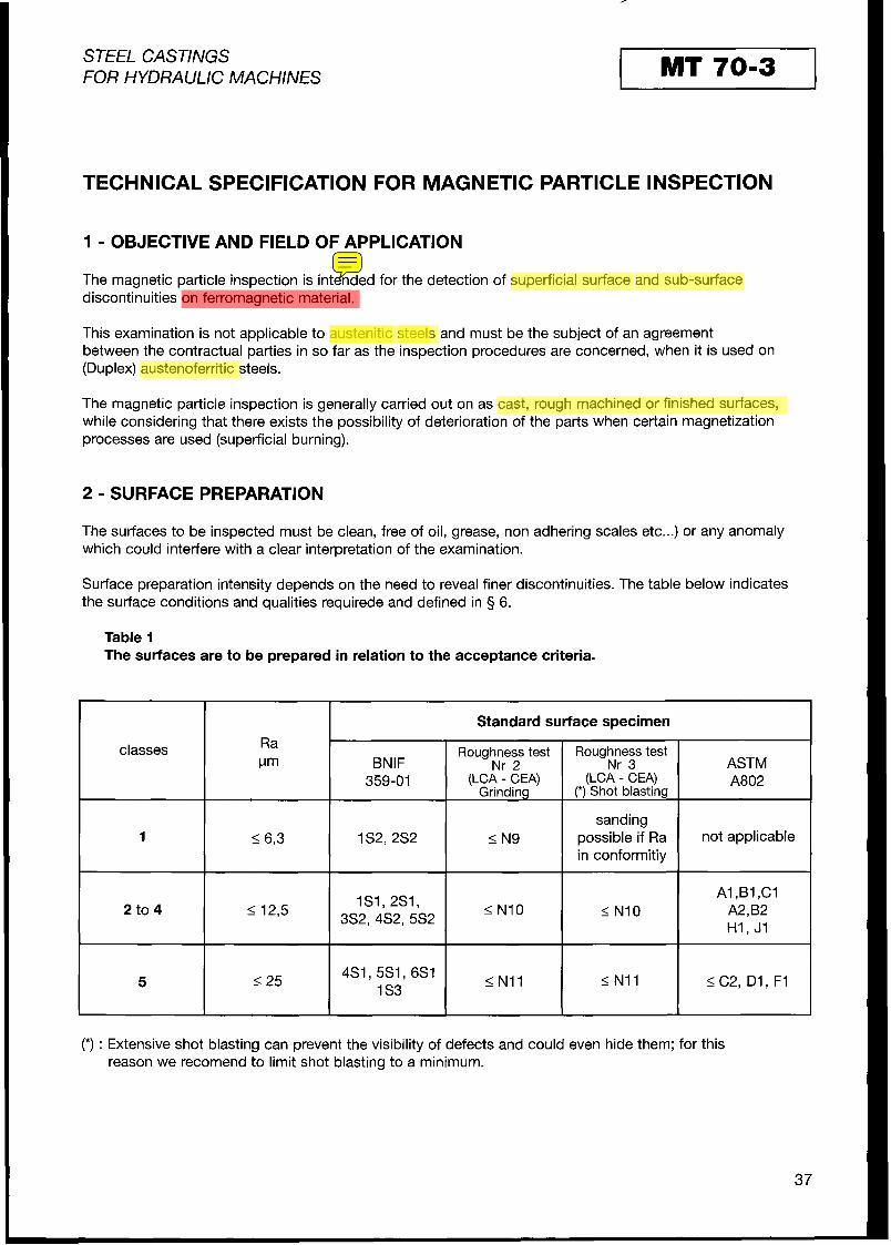
Table I The surfaces are to be prepared in relation to the acceptance criteria.
Standard surface specimen Raclasses Fm BNlF
Roughness test Nr 2
Roughness test Nr 3 ASTM
359-01 (LCA - CEA)Grinding
(LCA - CEA)(*) Shot blasting
A802
sanding 1 I6,3 1s2,2s2 IN9
in conformitiy possible if Ra not applicable
2 to 4 4 12,5 1s1,2s1,
3S2,4S2,5S2 < NI0 INI0 A I ,BI ,Cl
H1, J1 A2,B2
5 I25 4S1,5S1,6SI I N11 INI1 5 C2, D1,F11S3
(*) : Extensive shot blasting can prevent the visibility of defects and could even hide them; for this reason we recomendto limit shot blasting to a minimum.
37

STEEL CASTINGS MT 70-3FOR HYDRAULIC MACHINES
3 - MAGNETIZATIONMETHODS
3.1GENERAL
3.1.1 - The magnetic field must be of sufficient intensityto operate above the maximum magnetic permeability of the material. This requirement is generally met with a tangential field of 2000 N m (25 Oe) for unalloyed steels, (Average value of rectified current 1 alternation, effective value of alternating current); for allyoyed steels, higher fileds values maybe necessary. The value thus Chosen must be considered as a minimum on the totality of the area inspected. A magnetic field of excessive valuecan cause the appearances of aberrant indications because of Saturation.
3.1.2 - Magnetization is obtained through various processes indicated in5 3.2 and 3.3. These processes are not equivalent to each other with regard to : - the uniformity of the magnetization obtained - the depth of detection - the intensity of the tangential magnetic field obtained - the implementation conditions - the most favourable organization for detecting discontinuities. T0 insure that all orientation discontinuities are detected, it is necessary to use at least two directions of magnetization which should preferably be perpendicular to each other.
Regardless of the process or processes Chosen by the User, their efficiency will have to be demonstrated. A particular procedure may be requested by the Manufacturer.
3.2 MAGNETIZATION THROUGH THE PASSAGE OF MAGNETIC FLUX 3.2.1 - Magnetization by electromagnet (Yoke technique)
The use of this type of apparatus allows the control of finished surfaces. The air gap between the poles and the Part must be limited to a minimum to avoid magnetic leaks. This mode of magnetization reveals discontinuities of which the significant dimension is perpendicular to the axis connecting the poles of the apparatus. The electromagnet will necessarily be energized using an alternating current.
3.2.2 - Magnetization by coil and cable winding The magnetization obtained through winding a cable around a part or a section of a part in Order to create a coil allows the obtaining of high field value. (See 3.1.1) This mode of magnetization reveals discontinuities of which significant dimension is perpendicular to the axis of the coil.
3.3 MAGNETIZATION BY CURRENT PASSAGE 3.3.1 - Local magnetization by meansof electrodes
This mode of magnetization reveals discontinuities,the significant dimensionof which is parallel to the direction of the current. Particular precautions must be taken during the use of this process which may severely damage the Parts, particularly finished Parts: - The apparatus must be equipped with an opening and closing switch for the electric circuit in Order to
switch on the current only when the electrodes are in contact with the Part so as to avoid parasitic arcing.
- The current intensity and the duration of magnetization must be determined in a way to limit, as much as possible, local overheating at the Points of contact.
- The electrodes must be equipped with low filsion meta1 tips.
3.3.2 - Overall magnetization by current Passage. This mode of magnetization reveals discontinuities, the significant dimension of whichis parallel to the direction of the current. Precautions must be taken to limit local overheating at the Points of contact.
38
STEEL CASTINGS MT 7013FOR HYDRAULIC MACHINES
3.4 INFLUENCE OF TIiE NATURE OF THE CURRENTS The electric currents used for magnetization throughthe Passage of flux or through the Passage of current in the part, have an influence on the Performance of the magnetic particle inspection with the following characteristics:
- Alternatingcurrent : The eddy currentsmaintain the magnetic fluxon the surface; slightly sub-surface discontinuities or discontinuities connected to the surface are detected very well regardless of the shape of the part.
- Rectifiedsingle phasle current, onealternation (R1A): This mode is an intermediateonebetweenthe alternating and direct currents.
- Rectified single phase current,two alternations (R2A) : It is related to direct current and is convenient for parts of simple configuration. It allows a deeper detection depending of the dimensions of the discontinuities.
4 - INSPECTIONMATERIAL
4.1CURRENTGENERATOR Generators are used for magnetization through Passage of current (generally in the part or locally by means of electrodes) or for magnetization by the Passage of flux (use of wire coils). They must be able to supply high intensity current at low voltage. The currents supplied may be:
- alternating - rectified one alternation - rectified two alternations.
These devices and their instrumentation, if any, must be verified periodically using modalities defined by the User.
4.2ELECTROMAGNET$ Portable electromagnets are used to produce local magnetization through the Passage of flux. These devices must be verified periodically in Order to make Sure that they can lift a ferritic mass of 4.5 kg with a distance of 150 to 200 mm between poles.
4.3 TYPES OF AGENTS Agents consist of fine grain ferromagnetic powders of low residual magnetism which may be used dry (dry powder) or in a liquide suspension (liquid ink). These magnetic powders exist in two types: - magnetic powders of which their own colour is used (grey orblue depending on their nature). - magnetic powders with composite grains with a ferromagnetic core coated with a Pigment which is visible
either under white light or under ultra-violet rays. The agents used must hlave a granular concentration and a colour to insure adequate sensitivity andcontrast for the use for which it i$ intended. The concentration of liquid inks in magnetic powder is the one prescribed by the supplier. It may be verified for indication purposes using the ASTM pearshaped tube. It is generally of 1.2 to 2.4mVl concentration for black inks and 0.1 to 0.4 ml/l for fluorescent inks. The efficiency of the produdt used will be checked using a test piece placed on the Part being inspected (Berthold, AFNOR or ASTM test piece for instance, see 5 4.4). The Quality Sheet will specify the product to be used.
4.4 METHODS FOR VERlFlCATlON OF THE MAGNETIZATION CONDITIONS The magnetization conditilons aswell as the quality of the indicators can be checked using a magnetization test piece AFNOR, Berthold or ASTM. Nevertheless, it should be noted that the appearance of an indication On a test piece is not a sufficient element to judge the state of magnetization of the examined piece. The realconditions of magnetization can only be verified by means of a Hall probe to measure the tangential magnetic field.
39

STEEL CASTINGS FOR HYDRAULIC MACHINES
5 - OPERATING METHODS
5.1 CHOKE OF THEMAGNETIZATIONMETHODS The choice of magnetization method is dependent on the geometry, the steel grade and the finishing condition of the parts to be inspected. It is determined as well by the orientation, and the presumed depth of the discontinuities sought. Combinations are possible. The methods Chosen must allow for a magnetization in two directions, mostly at right angle to each other and must meet the requirements of§ 3.
5.2 MAGNETIZSTION USING ELECTROMAGNETS (YOKE TECHNIQUE) OR PASSAGE OF CURRENT BY MEANS OF ELECTRODES (PRODE TECHNIQUE).
T0 facilitate the control of large parts through local magnetization, the surfaces can be marked out in Squares in elementary areas using chalk. The poles of an electromagnet (fig. 1 ) or the electrodes (fig.2) are placed as shown in the following examples:
Figure 1 Figure 2
The dimensions of the Squares must be such that the distance between the poles or the electrodes and the recovering of the successive magnetized surfaces allowto insure at all the Points of the examined area a tangential magnetic field in conformity with § 3.3.1.
If no field measuring equipment is available, the magnetization condition is fullfilled ,if a effective intensifiy of current50 A per cm of distance <Cd>> between the electrodes is obtained; the elementary inspected area for each Position will be that defined by the illustration shown in the margin.
For certain ferromagnetic stainless steels, the intensity of current has to be raised; values of about 70 A /Cm may be necessary.
5.3 APPLICATION OF AGENTS 5.3.1 - Use of dry powders (limited to classes 3 to 5)
The surfaces examined must be completely dry. The magnetic powder spread over the area should be made up of a fine uniform coating by adequate means during magnetization. While maintaining the magnetization, the excess of powder should be blown off carefullyso as to leave only the indications created by the discontinuities.
40
I STEEL CASTINGS I MT 7013FOR HYDRAULIC MACHINES
5.3.2 - Use of magnetie inks The magnetic ink will be applied by flowing or preferably by spraying over the examinedarea during magnetization. Magnetization mwst be maintained for a while after theliquid has been applied, so that the indications can stabilize and in Order not to alter the already formed indications. It is important to insure the homogeneity of the ink.
5.4 CONDITIONS OF OiBSERVATlON OF MAGNETIC INDICATIONS VisualObservationof themagnetic indications should becarriedout with the nakedeyeorunderslight magnification (maximum3 fold). For an examination under white light the area examined must be lit with natural or artificial lighting corresponding to at least 500 Iux. In case fluorescent products are used, the part or area examinedmust be located in a dark area, where the level of white light will not exiceed 40 Iux. Observation is made under ultra-violet light of at least 800 vw/cm2 of intensity (ASME Code, sect. V ).
5.5 INTERPRETATION OF RESULTS Discontinuities are revealled by a concentration of the ferromagnetic particles of the agent, showing leaks in the magnetic field. However, all visible indications don't necessarily correspond to defects, false indications may be caused by any of the following: - lrregular geometry (Change of section) - Excessive roughness - Excessive Variation in rnagnetic permeability (welds, local peening etc...) - Excessive intensity of rnagnetic field - Excessive remanent magnetization.. Incaseof doubt supplementary investigationsmust be carried out after having modified the examination conditions (improvement of the surface condition, modification of the conditions of magnetization, etc...).
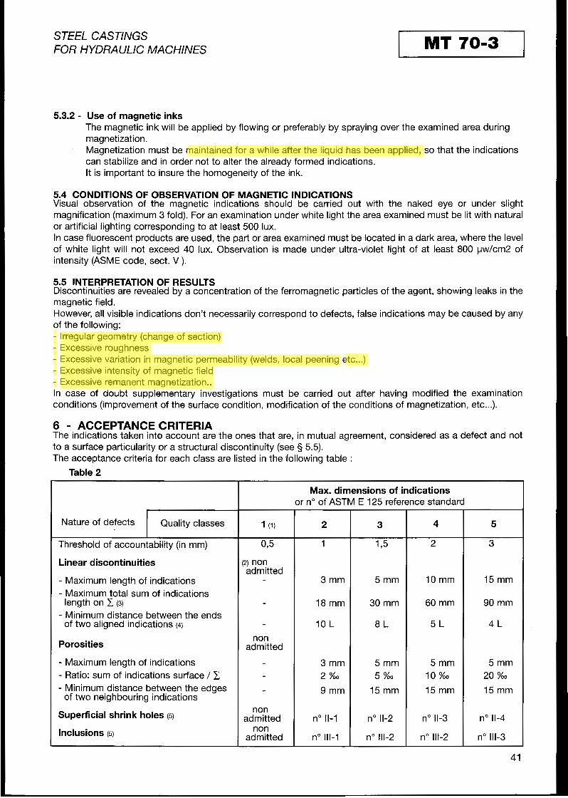
6 - ACCEPTANCECRlTERlA The indications taken into account are the ones that are, in mutual agreement, considered as a defect and not to a surface particularity or a structural discontinuity (See 3 5.5). The acceptance criteria for each class are listed in the following table :
Table 2
Max. dimensions of indicationsr or no of ASTM E 125 reference Standard
Nature of defects Quality classes 1 (1) 2 3 4 5
Threshold of accountablility (in mm) 03 1 175 2 3
Linear discontinuities 2) non admitted
- Maximum length of indications 3 mm 5 mm 10 mm 15 mm - Maximum total sum of indications
length onC (3) - 18 mm 30 mm 60 mm 90 mm - Minimum distance betvveen the ends
of two aligned indications (4) 10 L 8 L 5 L 4 L non
Porosities admitted
- Maximum length of indications - 3 mm 5 mm 5 mm 5 mm - Ratio: sum of indications surface / C - 2 %o 5 %o 10 %o 20 %o
- Minimum distance between the edges 9 mm 15 mm 15 mm 15 mmof two neighbouring indications
Superficial shrink holes(5) non
admitted no 11-1 no 11-2 no11-3 no11-4 nonlnclusions (5) admitted no 111-1 no 111-2 no 111-2 no111-3
41

residual magnetization.
STEEL CASTINGS MT 7013FOR HYDRAULIC MACHINES
(1) Classe 1 =Special class (highly stressed, critical areas, for example areas to be welded) Concentrations of numerous small indications,even of pin holes, will lead to a grinding of the surface in question to examine the evolution of the indications : in case the indications tend to lengthen and to rejoin one another, the affected area will be repaired.
(2) Cracks and lack of fusion are not acceptable in class 1.
(3) C : Reference surface identical with the surface of the reference photographs shown in ASTM Standard E 125 i.e. approx. 100 X 160 mm.
(4) L : Length of the longest indication.
(5)In case of disagreement and if the nature of the defect cannot be identified, the indication will be considered to be a linear discontinuity.
7 - CLEANING - DEMAGNETIZATION
7.1CLEANING At the conclusion of the examination, the residual products are to be removed using adequate cleaning products.
7.2 DEMAGNETIZATION Demagnetization of the parts may be requested by the Manufacturer, who will specify on the Quality Sheetthe +admissible As a reference, residual magnetization of less than 600 N m (8 Oe) will eliminate any Problems with adhering Chips.
8 - INSPECTIONREPORT
The inspection report must indicate : - ldentification of the Founder, the Manufacturer or the Designer - ldentification of the Casting (heatNr - traceability) - Steelgrade of the Casting - Designation of examination documents used : reference to the present specification, Quality Sheet ... - Stageofmanufactureat inspection - Mode of surfacepreparation - Mode of magnetization, the device used, type of current, nature of the revealing agent - Examination conditions - Areas inspected - lnspection results - Name,signatureand certification of inspector - ldentification of the firm in Charge of the inspection if sub-contracted - Date of inspection and signature of the responsable Person for inspection.
42

STEEL CASTINGS UT 7013FOß HYDßAULlC MACHINES
TECHNICAL SPEClFlCATlON FOR ULTRASONIC INSPECTION
0 PREAMBLE
The ultrasonic examination of Cast steel parts allows the detection of possible internal defects and to estimate as for as possible, their nlature, their dimensions and their Position inthe section under examination.
The inspection method described in this technical specification is based on the reflection of ultrasonic waves produced by a defect or the opposite surface of the part and is visualized by an echo on the screen of the apparatus (method of echo pulse ultrasonic testing).
The Operator manually shifts the probe by applying it on the surface to be inspected which is covered with couplant (contact technique).
The choice of the probe depends on various Parameters (geometric shapeof the parts, acoustic permeability to ultrasound, type of dePects sought).
For this research, the types of probes that are available are:
a) Standard longltudinal wave probes. b) Standard transverse wave angle probes. C) Probes with separate transmitter and receiver (SE type) for longitudinal wave or angle probes for transverse
wave.
0.1 PART 1 :LONGITUDINAL WAVES EXAMINATION
This ultrasonic examination using normal longitudinalwave probes with flexible membrane is applied in most cases to identify and locate defects in steel Castings.
0.2 PART 2 :TRANSVERSE WAVES EXAMINATION
This ultrasonic examination, which uses transversewave angle probes is more specific to control areas assembled or repaired by welding, for characterisation of indications and for controls of weld ends ...
The examination must be specified in the Quality Sheet or inthe technical specification of the Designer (probe 4 used, areas to examine, acceptance criteria) and must be defined during the call for tender and Placement of the Order.
In the absence of specification, the founder will use the technique described in part 1.
Note :
Ultrasonic inspection has its limitation and can only give an indication of the type of defect revealed by the ultrasonics.
Ultrasonic inspection and radiographic inspection do not supply indications which are directly comparable.
For the ultrasonic inspection of the Cast steel parts of austenitic or austenoferritic (Duplex) steels, Special measures must be specified by the parties involved.
The application of longitudinal wave angle probes is not considered in this specification.
43

I STEEL CASTINGS I UT 70-3FOR HYDRAULIC MACHINES
PART 1
LONGITUDINAL WAVES EXAMINATION
1.1 OBJETIVE AND FIELD OF APPLICATION
This specification outlines the measures to be implemented for ultrasonic inspection of ferritic or martensitic steel Castings, whose thickness varies between10 and 600 mm. For parts under or over these limits, the control method must be defined by the parties involved.
Its purpose is to detect possible internal defects in the parts, to designate the indications and to define the acceptance criteria.
It applies to the pulse echo ultrasonic testing with longitudinal waves (normal longitudinal wave probe).
1.2 METHODS USED
The methods described in this specification are :
either plot a CCDistance Amplitude Curve>>(DAC) from the deflection of longitudinal waves obtained on flat bottom holes on reference blocks.
or use the existing reference diagrams (AVG method).
The choice of either of these methods for inspection of parts will be specified in the Quality Sheet.
The normal longitudinal probe is manually displaced on the surface of the part to be examined. Interna1 discontinuities resulting in the appearance of a pulse echo and/or the decrease of the back echo when this back echo can be obtained in an area having parallel surfaces, are analysed while considering size, amplitude, Position and the nature of the defect. The results obtained are compared to the criteria of acceptability.
1.3 ULTRASONIC INSPECTION MATERIAL
1.3.1 APPARATUS
Characteristicof the apparatus: :
- The pulse generator will allow the Performance of tests at frequencies varying between1 and 5 MHz using Standard probes or separate transmitedreceivertype probes.
- Visualization is of type A.
- The apparatus will be equipped with a calibrated amplification control ,graduated in dB, adjusted by increments of at least 2 dB.
The verified characteristics are :
- The linearity of the amplification: The difference will be less than * 2dB over the entire scale used. - The time base linearity or the horizontal linearity: The difference should be less than2% of the measuring
range. - Vertical linearity: In the absence of a threshold the difference should not exceed 5% of the height of the screen.
All these verifications should be made for each generator:
- Upon its purchase - After repair - At least once a year.
A calibration report is produced. Every apparatus must have a labe1 indicating the date of calibration validity.
44

STEEL CASTINGS UT 7013FOR HYDRAULIC MACHINES
1.3.2 PROBES
The nominal frequency of the probes andthe dimensions of the piezo-electric Chips are Chosen subject to the nature, the dimensions andthe geometry of the part to be examined and the type of defect sought. The recommended frequency is2 MHz.
One can use either of the following two longitudinal wave probes:
- Standard longitudinal wave probe These probes are often used with a flexible protective membrane. The dead Zone must be as short as possible.
- Separate transmitter and receiver probes( twin probe) These are recommended for the detection of surface defects and defects in thin parts 5 50 mm. The converging area of these probes with separate transmitter and receiver must be adapted to the inspection to be performed.
The methods of use are specified in the Quality Sheet. In the absenceof specific indications, a Standard longitudinal wave probe will be used.
1.3.3 OPERATIONS T 0 PERFORM DAlLY ON THE APPARATUS AND AT EVERY CHANGE OF SHIFT
- Verification of physical condition and external appearance of the apparatus (pulse generator, probe, cable). - Quick verification of the calibrated amplifier. - Verification of sensitivity andof the resolution power of each probe used.
a) Sensitivity
A plastic insert from the international calibration block IIW A2 will be used. The number of visible echoes on the oscillogram, Set at the maximum gain if necessary, should not be less than the number indicateal on table 1 for the frequency range Chosen with a Standard longitudinal wave probe of 20 to 26 mm in diameter.
Table 1 Minimal number of echoes
Frequency range Minimal numberof echoesMHz
0,5 to 1,3 5 > 1,3 to 1,8 4
,8 to 2,6 (*) 3>I 2,7 to 5,O 2
(*) Recommended range
45
STEEL CASTINGS UT 7013FOß HYDßAULlC MACHINES
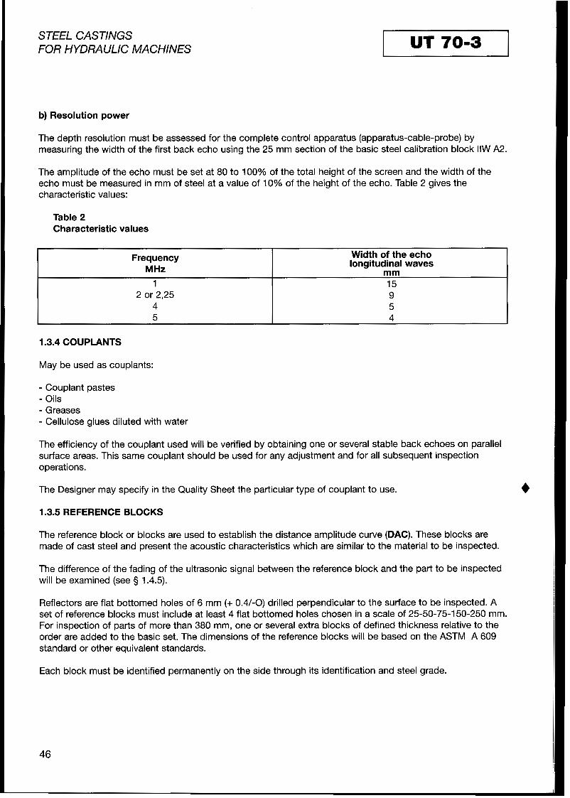
b) Resolution power
The depth resolution must be assessed for the complete control apparatus (apparatus-cable-probe) by measuring the width of the first back echo using the 25 mm section of the basic steel calibration block IIW A2.
The amplitude of the echo must be Set at 80 to 100% of the total height of the screen andthe width of the echo must be measured in mm of steel at a value of 10% of the height of the echo. Table 2 gives the characteristic values:
Table 2 Characteristic values
Frequency MHz
Width of the echo longitudinal waves
mm 1 15
2,25 2 or 9 4 5 5 4
1.3.4 COUPLANTS
May be used as couplants:
- Couplant pastes - Oils - Greases - Cellulose glues diluted with water
The Designer may specify in the Quality Sheet the particular type of couplant to use.
1.3.5 REFERENCE BLOCKS
The reference block or blocks are used to establish the distance amplitude curve (DAC). These blocks are made of Cast steel and present the acoustic characteristics which are similar to the material to be inspected.
The difference of the fading of the ultrasonic Signal between the reference block and the Part to be inspected will be examined (See 9 1.4.5).
Reflectors are flat bottomed holes of 6 mm (+ 0.4/-0) drilled perpendicular to the surface to be inspected. A Set of reference blocks must include at least 4 flat bottomed holes Chosen in a scale of 25-50-75-150-250 mm. For inspection of parts of more than 380 mm, one or several extra blocks of defined thickness relative to the Order are added to the basic Set. The dimensions of the reference blocks will be based on the ASTM A 609 Standard or other equivalent Standards.
Each block must be identified permanently on the side through its identification and steel grade.
46

I STEEL CASTINGS I UT 7013FOR HYDRAULIC MACHINES
1.4 INSPECTION CONDlTlONS
1.4.1 STAGE OF INSPECTION
Ultrasonic inspection is always carried out after quality heat treatment.
1.4.2 AREAS T 0 BE INSPECTED
The area or areas to be inspected and the extent of inspections are specified in the Quality Sheet..
- 100% ultrasonic testingsymbolized by an X on the Quality Sheet in the space corresponding to the area in question. The probe is shifted along parallel lines with recovering so as to examine the entire area successively.
- Spot check inspectionsymbolized by QL, QP or SL.
QL followed by a number: The probe is shifted along the lines of a squared or chequered area; the number following the Symbol indicate the squaring pitch in mm.
QP followed by a number: The probe is placed successively over each intersection of linesas described above.
SL the probe is shifted along lines defined for each case.
For Spot check inspections the following regulation will be applied :
- T0 avoid the application of the clause mentioned in 5 4 of the <<INTRODUCTION>>, the Designer is to define clearly, at the latest when passing an Order, the exact location of the intersection of the lines.
- If a defect is revealed its extent will be determined by inspecting the adjacent areas.
- The guarantee for a qulality class specified being met on the entire area under examination depends on the squaring pitch and on the acceptance criteria required.
1.4.3 SURFACE PREPARATION
The Quality Sheet will prescribe the surface finish required forthe inspection considering the acceptance criteria and the probes used. The surfaces to be inspected on steel Castings must be such that the couplants between the probe and the part will not have a significant influence on the sensitivityof the examination. The surfaces should be without ondulations which could hinder the contact between the probe and the part. The surfaces to be inspected must be free of rust, scales, weld spatter or other irregularities which would interfere with the transmission of ultrasonic waves orthe movement of the probe. The surface finish must at least correspond to samples 2S1 (for surfaces cleaned by Sand or Shot blasting) or 3 S2 (for ground surfaces) of the BNlF Standard or subject to SCRATA A l (for sanded surfaces)or H1 (for ground surfaces). In general a surface finish corresponding to reference N10 (12.5,pm) as per ISO 1302 is acceptable. In case a separate transmitter receiver probe is used, the surface finish shouldn't be greater than 2S2 (Ra 26.3 Fm).
47

I STEEL CASTINGS I UT 7013FOR HYDRAULIC MACHINES
1.4.4 ADJUSTMENT OF THE SPEED OF SWEEP
By adjustment of the horizontal sweep the maximum distance between the transmission point of the pulse and the most distant possible echo should be obtained considering the adjustment limits of the apparatus. For calibrations only the distances between multiple echoes or between two echoes corresponding to distant reflectors of a known value may be used andnot the distance between the pulse transmission and the first echo.
Theway, therelativePositionof an echo is located on the screen permits to determine the depth of the corresponding reflector.
1.4.5 ADJUSTMENT OF AMPLlFlCATlON AND INTENSITY
1.4.5.1 Use of reference blocks: (DAC Metbod)
The adjustment of amplification and intensity is carried out on indications obtained from artificial reflectors (cylindrical holes with flat bottom of the reference blocks). These adjustments are carried out simultaneously,the amplification threshold being brought back to the minimum. During these adjustments the intensity must be maintained as low as possible, the height adjustment of the reference echoes is obtained only through the adjustment of amplification.
Correction of ultrasonic energy absorption.
T0 consider, to a certain extent, possible differences in surface finish and or absorption of ultrasonic waves between the Casting under inspection and the reference block, the amplification can be modified as follows:
- Place the probe in an area of the Casting which has parallel surfaces and whosethickness is equivalent to that of the block and whose surface finish and preferably whose internal structure are representativeof the rest of the Casting.
- Place successively the probe on the reference block (outside the area with artificial reflectors) and on the Casting to be inspected.
Are to note :
- The two gains necessary to bring the back echo to a similar screen height. - The difference in gain g l indicates the necessary increase in gain in correction of ultrasonic energy
absorption.
The gain to be used for inspection corresponds to the gain used for establishing the distance amplitude curve, increased by g l
In practice, this correction is made only if g l > 2dB
Adjustment based on indications obtained from artificial reflectorsof the reference block
Two modes of adjustment may be used:
a) Distance amplitude curve (DAC)
The probe is placed in a way to obtain the maximum pulse echo onthe reflector giving the strongest pulse and the adjustment is madeso as to bring its amplitude to 80% approx of the height of the screen.
The maximum amplitude of the echoes received on each of The curve joining thesethe other reflectors is noted. Points constitutes the distance amplitude curve. Except in the case of small thicknesses, this curve is plotted with a minimum of3 Points.
48

I STEEL CASTINGS I UT 7013FOR HYDRAULIC MACHINES
If the amplitude of the echo received on one reflector is less than20% of the height of the screen, a fractioned distance ampllitude curve will be plotted as indicated in figure 1.
A new adjustment is madeso as to bring the amplitude of this echo to approximately 80% of the screen height.
b) If the apparatus usedallows it, the distanceamplitudecurve may be replaced bya diagram of the amplification values necessary to bring the amplitude of the echoes on each reflector at the Same height (approximately 80% of the screen height).
Figure 1 :Distance amplitude curve DAC
Y0
80
20
1.4.5.2 Use of existing reference diagrams :AVG Method (DGS method)
The AVG method is similar to the DAC method in so far as the objectives are concerned but it doesn’t require artificial reflectors for plotting.
For most of the Standard probes and for probes with separate transmitter/ receiver, the manufacturers suggest using abacus type AVG screens which are placed on the apparatus screen (respectively electronic curves on digital equipement). The abacus screen remains valid only if probesof the Same type have similar characteristics. Acoustic absorption resulting from, the material must not be neglected and the method of correction of ultrasonic energy absorption described in the DAC method is applicable. The adjustment of sensitivity is obtained from the reference echo which is brought to the screen of the ultrasonic apparatus to a given reference height.
1.4.6 FREQUENCY OF VERlFlCATlON OF THE ADJUSTMENTS
These adjustments must be made at the beginning of each inspection sequence and must be verified at the beginning and at the end of each shift and every time the Operator suspects a drift in the installation.
Every verification is considered adequate if the drift noted stay smaller ask 2 dB. Otherwise, the inspection must be carried out again as of the previous verification.
1.5 METHOD OF SGARCHING FOR DEFECTS
In all the areas that have to be 100% inspected, the Operator must carry out a complete sweep making Sure that there is a systematic recovering of at least10% of the probe diameter.
The Speed of shifting of tlhe probe must be adapted to the examination conditions and must not exceed 150 mm/s.
The search for defects is made with an adjustment corresponding to as great a sensitivity as possible considering the electronic noise (grass) (approximately+ 6dB).
49

STEEL CASTINGS UT 70-3FOR HYDRAULIC MACHINES
INDICATIONS T 0 BE INVESTIGATED:
The indications to be investigated are:
- lntermediate echoes, - Any back echo attenuation which is not explicable by the geometry of the Casting.
Sometimes certain indications are impossible to interpret or may let presume the presence of flat defects as for example Cracks. These indications will be considered to be 4ndications to be confirmed,, (See § 1.8) in particular for areas in which significant repairs have been made.
1.6 CHARACTERIZATION OF INDICATIONS
1.6.1 LOCATION
The indications are localized relative to a known and defined System of marking.
1.6.2 DlMENSlONlNG OF INTERMEDIATE ECHOES OBTAINED
1.6.2.1 Dimensioning in amplitude from the distance amplitude curve(DAC) obtained over the flat bottomed holes.
a) If the distance amplitude curve is used in conformity with 1.4.5.1a the maximum amplitude of the indication is compared to the Ordinate of the curve for the Same sonic path and in the Same conditions of adjustment used for its establishment. The extent of the defect is expressed in percentage of the distance amplitude curve.
b) If the adjustment is made in conformity with the methods defined in9 1.4.5.1 b, having determined the depth location of the indication, the adjustment is compared to the indication obtained for the artificial reflector which is the closest and whose amplitude is taken as a reference. The extent of defect is expressed as a percentage of the reference amplitude.
1.6.2.2 Dimensioning of amplification using theAVG method
The maximum amplitude obtained on the indication is compared to the AVG abacus curves for the Same sonic path and in the original adjustment conditions. The degree of the indication is expressed in equivalent diameter
1.6.2.3 Dimensioning of indications
lndications which can be mesured in surface The dimensioning involves demarcating the defects noted. The outline of the defect is defined by the Positions of the centre of the probe corresponding to an amplitude of the echo equal to half of the maximum amplitude of the echo of the defect being inspected (the -6 dB method). This demarcation is made with the Same probe or with a similar type probe in the Same Operating conditions used to detect the defect. This demarcation requires the prior marking of the defects upon their detection. T0 demarcate the defect, the probe is shifted in all directions over the probed surface. The outline of the defect defines the surface S of this defect; the length of the defect is the largest dimension of the whole defect.
I STEEL CASTINGS I UT 7013FOR HYDRAULIC MACHINES
Note : Ifthe investigated sutface is not relatively flat, determining the real surface of the defective area may require a Sketch.
lndications which are not measurable in surface If the dimension of thle indications is inferior or equal to the diameter of the ultrasonic beam, the indication is described as non measurable in surface. The following graph which is taken from the Euronorm CENiTC 190 N224: 1993 (Figure 4) will be helpful . The indications non measurable in surface will be evalueted as per 51.7ccACCEPTANCE CRITERIA>>.
m n Uä j E+;F
0 E 150 -L-CJa, s .L
4- 3-Q, o mE '"U .sn 5 - X20 X 22
1....1 M H z I L 0 10 t - 2....2MHz/L010 3....1 MHz I L 0 24 4. . . .2MHzIT08x9
100 5....4 MHz I L 0 10 6 . 2MHz I L 0 24 7....4 MHz I T 0 8 X 9 8 . 2 MHz I T D 8 X 9 9....4 MHz I L 0 24
10....5 M H z / L 0 2 4 11....4 M H z I T 0 2 0 x 2 2
70 -
60 -
50 -40 -
30 -0
-20 1
10 -L
0 100 200 300 400 500
Aproximate values of the length of thenear field and the sonic beam diameter (-6dB) in the far field of the monocrystal Standard probes based on the sound path (represented by curves 4,7,8 and 11 for angle probes). It is the smallest of the two axes of the elliptical sonic field.
51

1 STEEL CASTINGS I UT 7013FOß HYDßAULlC MACHINES
1.6.3 DlMENSlONlNG RELATIVE T 0 THE DECREASE IN BACK ECHO
1.6.3.1 Dimensioning in amplitude
Any area in which a decrease in back echo is noted is characterized by the formula
- where AF = F0 - F F0
F0 = Height of the back echo in a sound area with parallel Walls of similar thickness as the area to be examined.
F = Height of the back echo in the examined area with parallel Walls.
1.6.3.2 Dimensioning in geometry
F0 is brought to a height of approximately80% of the height of the screen. The dimensioning involves the demarcation of the loss of back echo AF. The outline of the loss of the back echo is defined by the Positions of the centre of the probe corresponding to AF maximum, minus50% ( see Figure 2). For each new Position of the probe, the Position of the beam axis is marked; the outline obtained by joining the Positions of the beam axis defines theS surface of the defective area.
Figure 2 :Demarcation of the loss of back echo
I I 80%
7
Dynamits of the loss of back Wall-echo
52

I STEELCASTINGS UT 70-3FOR HYDRAULIC MACHINES
1.6.4 CUMULATED INDICATIONS
Two neighbouring defects must be considered as constituting only one defect, of equal surface to the sum of both, if the distance which separates their outline is equalor less than the largest dimension of the smallest defect (figure 3).
Figure 3 :Cumulation of 2 neighbouring indications
1.7 ACCEPTANCECRITERIA
The acceptance criteria may Cover the height of the flow echo (defect echo), the equivalent diameter AVG, the attenuation of back echo, the number of non measurable indications, the surface of each elementary area,the total surface of the cumulated elementary areas.
lndications which exceed the acceptance criteria limits may be repaired or may ((require confirmation>>; the decision in this regard will be left to the Designer (See § 1.8).
Definitions
D Height of the maximum echo on the defect after return to the calibrated amplification.
R Height of the reference curve at the Same depth.
F Height of the back echo in the inspected area with parallel surfaces
F0 Height of the back echo on the sound area with parallel surfaces, of the Same thickness as the area to be inspected.
AF = F0 - F
S Surface of the elementary areas obtained by grouping 4ndications to be recorded,, applying the method described in !j 1.6.2.3. et 1.6.3.2.
( ) Numbers 1to9 betweenthe pamthesesindicate that one should&er tothe legend at the end of §1.7,page 56.
Table 3 Sets for both the DAC and AVG methods, the classes of quality 1 to 6 in Order of decreasing severity, the notation threshold, the area of consideration of the indications and the attenuation of the back echo. Tables 4 and 5 Set the maximum admissible indications.
In a Same section, the Designer can determine several classes of severity. The repartition ofthe areas subject to the thickness of the part can be defined according to the legend (9). In this case the Designer stipulates on the Quality Sheet in thearea considered for example: ZONE IV Rz = Classe Rz = rim zone 2 See fig. 5 (page 57)
Cz = Classe 4 where cz = core Zone
53

I STEEL CASTINGS I UT 7013FOR HYDßAULlC MACHINES
Table 3 Threshold for notation
AMPLITUDE
Notation threshold Area of consideration
Class Method Method
Back Wall echo attenuation
AVG Method
Back Wall echo attenuation (3)
0
1 (5) I 0.15
equivalent
2
2 I 0.25 I % 2
25 I 0.25
(mm)equivalent
2
AF- 2 F0
% 2
3 0,25 25 0,50
3 0 3 50 1
( ) See Page 56
Table 4
NUMBER OF LOCALIZED INDICATIONS(2) (indications not mesurable in surface) Maximum acceptable density per dm2 based on the area considered defined in Table 3 (4)
DEPTH INVESTIGATION OR Acceptable THICKNESS OF THE STEEL CASTING distance
IN THE CONTROLLED AREA (mm) between 2Class indications
2 mm > 50 a 100
12
10
8
54
Table 5
MESURABLE INDICATIONSIN SURFACE (6)
Limits of acceptance based on the area considered defined in Table 3 (4)
DEPTH OF INVESTIGATION OR THICKNESS OF THE STEEL CASTING IN THE AREA INSPECTED
I50 mm > 50 to 100 mm > 100 to 250 mm > 250 to 600 mm
'lass Individual S ~cumulatdSIndividual SExtension incumulatedS
Surfacedepths ~ r f a ~ eSurface (Cm2) (M(Cm9(M
%
f i in depth
%
Individual S~ ~ ~ Surface (Cm9
cumulatdSIndividual SExtension incumulatdSi ~ ~ suwSurfacedepths ~ r f a ~ e (M(Cm2)(4
%
~~~~~i~~ in depth
% (7) (8) (7) 8
3 2 25 10 3 35 10 15 100 10 40 200 10
4 8 50 15 12 100 15 25 150 15 60 300 15
6
5
20
15
200
100
20
20
30
25
250
150
20
20
50
40
300
200 20
200
100
40020
350
20
20 CII
: ) See Page 56
rlö6

STEEL CASTINGS UT 70-3FOR HYDRAULIC MACHINES
LEGEND for tables 3,4 and 5
(1) Cracks are unacceptable.
(2) When the dimension of the indication is smaller than the diameter of the ultrasonic beam, it is recommended to use an SE probe (separate transmitter receiver) or a probe whose limit of the near field is I than the distance in depth of the defect.
(3) The indications with a diminishing back Wall echo of> 50% and/or with an attenuation of the back Wall echo without the appearance of defect echo in the area of consideration and of surface Superior to that indicated in Table 5, will be the subject of further investigations (See 3 1.8 lndications to be confirmed).
(4) Any accumulation of amplitude indications included between the threshold of notation and the area of consideration must be considered as an indication 40 be confirmed)) See 3 1.8. Acceptability of repair decisions will be taken on a caseby case basis. lsolated indications which seem to originate from several defects located at different depths will be considered as multiple indications.
(5) Classes 1 and 2 are resewed for exceptional requirements determined by the Designer. The inspection will be made using a probe with a separate transmitter receiver (of4 MHz wherever possible) for thicknesses or depths 2 50 mm. Beyond those thicknesses or probedepths, use a Standard perpendicular with a silence Zone (dead Zone) as short as possible.
(6) The dimension of the indication is greater than the diameter of the ultrasonic beam. The range is determined according to the - 6 dB method (See 3 1.6.2.3).
(7) It is the limit of acceptance ofthe sum of the elementaryS surfaces, of the indications noted on an examined surface of 1000 cm2 (approx. 32X 32 Cm).
(8) The maximum acceptable extension in depth of the indication is expressed in % of the examined thickness (See figure 4).
(9) Figure 5 indicates the distribution of areas in the thickness of a part.
Rz = Superficial areas (rim Zone) They are equal to 1/3 of the thickness of the Part in its delivery condition with a maximum of 30 mm
Cz = Median area (core Zone) It is the area included between the two previous areas.
Note :
The demarcation between superficial and median areas is not always clearly defined when the Casting is of complex shape. When discontinuities are located at the limits of these areas, consultation between the Designer and the Founder or Manufacturer is necessary.
56 I

1 STEEL CASTINGS I UT 7013FOR HYDRAULIC MACHINES
Figure 4 :
Mesure of the depth extensionof the defect using a perpendicular probe
Sketch of oscillogram Position AProbe nPosition A
b d l 4 Position B
;Probe IPosition B B
e = t - (dl + d2)
Figure 5 :Distribution of areas in the thickness of a Part
I rim 20ne I
1/3 X t (max. 30 mm)
L
57

I STEEL CASTINGS I UT 7013FOR HYDRAULIC MACHINES
1.8 INDICATIONS uTO BE CONFIRMED,,
The indications 40 be confirmed,, will be the subject of additional investigations by using for example different types of probes so as to confirm or contradict the existence of a discontinuity and to indicate as much as possible the nature and the dimensions (See Part 2 - lnspection of transverse waves). The Designer will decide, taking into consideration the degree of solicitation of the area in question as well as the possible evolution of the defect under Service conditions. If the Designer so requires, a detailed report with Sketch will be established and transmitted to him. If necessary and if the Casting allows such inspection, confirmative radiographic inspection may be required, provided that the inspection criteria had been defined on the Quality Sheet when the Order was placed. These criteria only apply to 4ndications to be confirmed,, according to the present specification.
1.9 INSPECTION OF WELDED AREA (REPAIRS)
Unlessotherwiseagreed upon by the Designer, Founderand/orManufacturer,repairs by welding will be inspected under the Same conditions as those defined by the examination beforerepair. Howerer, the Designer may recommend that any <<major>> repairs be inspected as much as possible, so that repairs by welding be inspected using transverse wave probes (See Part 2 of the specification).
The methods of these supplementary inspections will be indicated on the Quality Sheet or in the Designer’s Specification (areas to be inspected, methods used, criteria of acceptance )
Definition of repairs considered <<major,>see chapter GE 70-3§ 5.1.2..
1.10INSPECTIONREPORT
The inspection report must indicate :
- ldentification of the Founder or the Manufacturer or the Designer. - ldentification of the Casting (heat number, traceability). - Steel grade of Casting. - Designation of examinationof documents used: reference to the present specification, Quality Sheet ... - Stage of manufacture at inspection - Mode of surface preparation. - Trademark and type of apparatus and probe used. - Conditions of calibration and adjustment. - Areas inspected. - Characteristics (Position, amplitude, surface) of theindication 2 the notation threshold. - lnspection results. - Name of the inspector, his signature and his certification. - ldentification of the firm in Charge of the inspection,if sub-contracted. - Date of inspection and signature of the responsible Person for inspection.
5%

1 STEEL CASTINGS I UT 7013FOR HYDRAULIC MACHINES
PART 2
TRANSVERSE WAVES EXAMINATION
2.1 OBJECTIVE AND FIELD OF APPLICATION
This specification is applicable, after an agreement between the Designer, the Founder or the Manufacturer, for carrying out complemenllary investigations, for the characterization of indications, for inspection of weid ends, for the examination of welds, or of areas repaired by welding, for the inspection of welded joints between two Parts. It defines the procedure to implement for ultrasonic inspection of ferritic or martensitic steel of more than 12 mm in thickness. It applies to the pulse echo method using transverse waves (angle probe).
2.2 METHODS USED
The methods described iln this specification involve :
- either the plotting of a 'LDistance Amplitude Cuwe>> (DAC) from the reflection of transverse wavesobtained on the generator of holes drilled parallel to the contact surface,
- or using existing reference diagrams (AVG method).
The choice of either method for the part as a whole will be specified in the Quality Sheet.
The angle probe is shifted manually over the surface of thePart to be examined. Interna1 discontinuities causing an echo are analysed (dirnensions, amplitude, Position, nature of defect).
2.3 ULTRASONICINSPECTIONMATERIAL
2.3.1 APPARATUS
The apparatus is identical to the one used in longitudinal waves (See 5 1.3.1).
2.3.2 PROBES
Transversewave probes: The recommended refraction angles are 45", 60" and 70", the frequency used will generally be included bellween 2 and 5 MHz
2.3.3 OPERATION T 0 PERFORM DAlLY ON THE APPARATUS AND EVERY CHANGE OF SHIFT :
- Verification of physical condition and external appearance of the apparatus (pulse generator, probe, cable). - Quick verification of the calibrated amplifier. - Verification of the direction of the beam in the vertical median plane of the probe (maximum squint angle2"). - Verification of the emergency point and the angle of refraction of the probe. - Verification of the resolution power.
59

I STEEL CASTINGS I UT 70-3FOR HYDßAULlC MACHINES
The depth resolution must be assessed for the whole apparatus (apparatus/ cable / probe) through the measure of the width of the echo obtained on the basic quarter round of the steel calibration block IIW A2.The time base is adjusted on 50 mm full scale in the transverse waves. Knowing that 91 mm of steel permeated by longitudinal waves correspond to 50 mm of steel permeated by transverse waves, the apparatus is adjusted by placing a perpendicular probe on the 91 mm thick calibration block as per figure6 PositionA. The perpendicular probe is replaced by the angle probe to analyse. It is placed on the calibration block as per figure6 Position B.
By adjusting the shift, one can See in the middle of the screen, the echo obtained on the calibration block quarter round (without changing scale). The amplitude of the echo must be adjusted from 80 to 100% of the total height of the screen and thewidth of the screen must be measured in millimetres of steel at a value of 10% of the height of the echo.
Table 6 Shows caracterstic values.
Figure 6 :Verification of the resolution power
/ Perpendicular probe
Angle probeI Position B
L 6 7 0 9
Table 6
Width of the echo Frequency
Transverse waves MHz
mm
1 2 or 2,25(*) 5
4 3 5 295
(*) Frequency recommended
60

STEEL CASTINGS UT 7013FOß HYDßAULlC MACHINES
2.3.4 COUPLANT
The couplant used is identical to that used in longitudinal waves (See 9 1.3.4).
2.3.5 REFERENCE BLOCKS (DAC)
The reference blocks are used to establish the Distance Amplitude Curve (DAC). They are produced in a steel Casting presentingacoustic characteristics as close as possible to the blocks used in longitudinal waves.
Under all circumstances, block and thethe attenuation difference of the ultrasound signal between the reference part to be inspected will be verified (See 9 2.4.5.1). The reflectors are made of holes drilled laterally at equal depths respectively at 1/4, 1/2 and 3/4 ofthe thickness of the reference block. The reference block dimensions will be produced in conformity with ASTM A 609, figure 4 and as indicated in table 7.
Table 7 Caracteristics of the reference blocks in relationto thickness
Thickness to inspect cctn CARACTERISTICS OF THE REFERENCE BLOCKS
or depth of the excavation
Thickness ccTw Location Diameter No of the block of holes of the holes
mm mm * 0,05 mm
< 25 1 25 or t 1/2 T 2,4
> 25 to 50 2 50 or t 1/4 T - 1/2 T - 3/4 T 3
> 50 to 100 3 100 or t 1/4 T - 1/2 T - 3/4 T 5
> 100 to 150 4 150 or t 1 /4T -1 /2T-3 /4T 6
> 150 to 200 5 200 or t 1/4 T - 1/2 T - 3/4 T 8
>200 to 250 6 250 or t 1/4 T - 1/2 T - 3/4 T 10
> 250 7 t 1/4 T - 1/2 T - 3/4 T (*)
(*) Above 250 mm, for each Segment of 50 mm, increase the0 of the hole by 1.6 mm.
Other types of reference blocks can be used. These blocks shaped like a parallelepipedon have a series ofcylindrical holes drilled from one end to the other, subject to the width of the reference block, parallel to the surface to be explored. The diameter of these holes is a function of the thickness to be inspected (as per table 7).
For a diameter equal to or less than 5 mm, the first hole will be drilled at 10 mm from the surface to be explored. The difference in depth between the next holes is of 20 mm.
For a diameter greater tlhan 5 mm, the first hole is drilled at 20 mm from the surface to explore. The difference in depth between the next holes is40 mm.
Each block must be permanently identified on its side using its reference identification and its grade of steel.
61
reflector
in mm
STEEL CASTINGS UT 7013FOR HYDRAULIC MACHINES
2.3.6 REFERENCE DIAGRAM (AVG)
The AVG method is similar to the DAC method in so far as its objectives are concerned but it doesn’t need any artificial reflectors for plotting. The reference diagrams proposed by the manufacturer for each type of probe is used (respectively electronic curveson digital equipement).
In the AVG diagrams, the relation between the length of the path of the sound waves and the amplification on the generating line of the circular section reflector, located perpendicular to the sound beam, is indicated as a Parameter.
T0 determine the sensitivity of testing, the diameter of the circular section reference reflector is used, based on the thickness of the material to be tested.
Table 8 Circular section reference reflector0, in relation to thickness or depth
Thickness sectioncontrolto Circular<ctwor reference excavation depth
Diameter mm
I25 2
> 25 to 50 275
> 50 to 100 3
> 100 to 150 4
> 150 to 200 5
> 200 to 250 5
> 250 to 300 6
> 300 to 400 7
> 400 to 500 8 -L
62

STEEL CASTINGS FOR HYDRAULIC MACHINES UT 7013
2.4 INSPECTIONCONDITIONS
2.4.1 STAGE OF INSPECTION
The ultrasonic inspection will always be performed after quality heat treatment, in case of inspection of repairs or construction welds, the inspection will be performed after the final heat treatment.
2.4.2 AREAS T 0 BE INSPECTED
The areas subjected to inspection and their range will be defined on the Quality Sheet if need be, subject to the following limitations.
2.4.2.1 Welded joints or repairs
The area subjected to inspection should include the welding and the area adjacent to it, based on the three examples in figures 7, 8 and 9.
Figure 7 :Full penetration weld between two parts
Weld
Figure 8 :Partial penetration weld or weld on supporting plate
Weldnot welded aerea
Imeta1 L support plate
Note for fiaures 7 and 8: The hatched lined areas correspond to the area of doubt in view of the limits of the method.
63

I STEEL CASTINGS I UT 7013FOR HYDRAULIC MACHINES
Figure 9 :Weld reparation
I Welding reparation
Leaend :
Areas a + b : Application of welding acceptance criteria Area C : Application of base meta1 acceptance criteria
2.4.2.2 Examples of pending welds or areasto be welded
The area subjected to inspection generally includes a20 mm space relative to the edge of the groove (example figure 10) or to the area to be welded (example figure 11).
Figure 10 :Pending weld Figure 11 :Hub area to be welded groove
,Groove
Over length I
T
The extent of the inspection includes 100% of the volume of area A
64

STEEL CASTINGS UT 70-3FOR HYDRAULIC MACHINES
2.4.3 SURFACE PREPAFRATION
The exploration surfaces must be free of any deposit, product, asperities which could hinder the transmission of waves or the free movement of the probe or which could provoke errors of interpretation (parasitic echoes). In cases of repair, the welds will be ground fine or machined. Unless otherwise specified, roughness Ra will not exceed 6.3 Fm.
2.4.4 ADJUSTMENT OF THE SPEED OF SWEEP
The sweep range maybe calibrated: - either in distance over which to sweep, - or in real depth of refleators.
2.4.4.1 Adjustment of ths distance swept
The adjustment is made wsing the fundamental steel calibration block IIW A2.
2.4.4.2 Adjustment of real depth of reflector
The adjustment is made from the artificial reflectors of the reference block indicated in § 2.3.5. The relative Position of anecho on the screen allowsto determine the real depth of the corresponding reflector.
2.4.5 ADJUSTMENT OF THE AMPLlFlCATlON AND THE INTENSITY
2.4.5.1Useof reference block defined in 2.3.5 (DAC method)
The adjustment of the arnplification and the intensity is carried out from indications obtained from artificial reflectors (cylindrical holeb in the reference blocks). Theseadjustments are carried out simultaneously, the amplification threshold being brought back to the minimum. During these adjustments, the intensity must be maintained as low as possible. The height adjustment of the reference echoes is obtained through the adjustment of the amplification.
Correction for ultrasonia energy absorption
T0 consider to a certain extent possible differences in surface finish and/or absorption of ultrasonic waves between the Casting under inspection and the reference block, the amplification will be modified as follows:
- Place the probe in an area of the Casting which has parallel surfaces and whosethickness is equivalent to that of the block and whose surface finish and preferably whose internal structure is representative of the rest of the Casting. This correction is made from the comparison of attenuations in the block and in the part over the Same path of the ultrasonic beam, with the help of a transverse waveprobe of the Same type (dimensions and frequency) as those used for inspecting the part.
65

STEEL CASTINGS I UT 7013 [FOR HYDRAULIC MACHINES
- Place two probes, one a transmitter and the other a receiver over the reference block as per figure 12. Note the gain necessary to bring the reception Signal to an amplitude equal to 80% of the height of the screen. Without modifying the adjustments, the two probes are then placed over the part to be inspected. The difference in gain g l is translated by the increase in the gain necessary for the correction of ultrasonic energy absorption. The gain to use during the examination corresponds to the gain used to plot the distance amplitude curve plus the gain g l . In practice this correction is carried out only if g l > 2dB.
Figure 12 :Correction for ultrasonic energy absorption
Transmitter probe
Adjustment from indications obtained from artificial reflectorson the reference block
Two methods of adjustment may be used :
a) Distance amplitude curve (DAC)
The principle to plot the distance amplitude curve is identical to that described for longitudinal waves (See Paragraph 1.4.5 .1 a) The maximum amplitude of the echoes obtained on cylindrical holes located at 1/4 T and 1/2T from the Same surface sounding and 3/4 T on the opposite surface is noted. Thecurve linking these differentPoints constitutes the distance amplitude curve. A fractioned distance amplitude curve is established when the amplitude of the echo obtained is less than 20% of the screen height. The Same adjustment may be obtained using other types of reference blocks as described in Paragraph 2.3.5.
b) When the apparatus so allows, theadjustment of the sensitivity is performed by taking note of the amplitudevaluesnecessary to bring the amplitude of the echoes oneachreflectorat the Same height (approximately 80% of the height of the screen).
2.4.5.2 Use of existing reference diagrams defined in Paragraph2.3.6 (AVG method)
The method is identical to that of longitudinal waves (See § 1.4.5.2) The acoustic absorption attributable to the material shouldn’t be neglected and the method of correction of transfer described for the DAC method is applicable.
2.4.6 FREQUENCY OF VERlFlCATlON OFTHE ADJUSTMENTS
The frequency of verification of the adjustments is identical to that defined in longitudinal waves (See § I .4.6).
66

1 STEEL CASTINGS 1 UT 70-3FOß HYDßAULlC MACHINES
2.5 METHOD OF SURCHING FOR DEFECTS
The method should allow the investigation of the whole area to be inspected. The refraction angle of the ultrasonic beam is included between 70 O and 45 O . It will be a function of the thickness to be inspected, of the geometric shapeof the Casting or welded joint and of the type of indications to be determined.
The sweeping method over the area to inspect, the Speed of shifting of the probe as well as sensitivity to the defects are identical to those defined for longitudinal waves (See 3 1.5).
INDICATIONS T 0 BE INVESTIGATED.
2.5.1 EXAMPLE OF A WELDED JOINT BETWEEN W O PARTS OR AN AREA REPAIRED BY WELDING
a) Detection of longitudinal indications
Longitudinal indications are those located in the Same direction as the direction of welding. Two sounding angles with a difference of at least10 to 15 O between them shall be used.
b) Detection of transverse indications
Transverse indications are those situated perpendicularly to the direction of welding. The indications will be detected in caseof non rnachined weldswith an angle of rotation of the probe relative to the direction of welding (See figure 13) and following two 180" directions for machined or ground welds (example figure 14).
machined Figure 14 :MachinedFigure 13 :Non welds welds
Angle of rotation of the probe 15 O 2 directions at 180" relative to the or 45" in case of ESW probe (direction of exploration 5 and 6) (Exploration direction I, 2, 3 and 4) Note: In case of ESW*, the supplementary
angle of rotation of the probe is 45" (supplementary exploration direction 7, 8, 9 and 10)
*ESW: Electroslag Welding
2.5.2 EXAMPLE OF PENDING WELDS, AREAS T 0 BE WELDED, INDICATIONS T 0 BE CONFIRMED OR COMPLEMENTARY INVESTIGATIONS.
In all the areas to be inspected, the Operator must carry out a complete sweep in all directions in Order to find indications producing an echo. Different types of angle probes will be used to obtain the maximum amplitude of the indication.
67

I STEEL CASTINGS I UT 70-3FOR HYDRAULIC MACHINES
2.6 CHARACTERIZATION OF THE INDICATIONS
2.6.1 LOCATION
The location of the indications is identical to that defined for longitudinal waves (See § 1.6.1).
2.6.2 DlMENSlONlNG OF ECHOES OBTAINED BY THE INDICATIONS
2.6.2.1 Dimensioningin amplitude from the distance amplitude curve(DAC) obtained on the cylindrical holes
The dimensioning in amplitude is identical to that defined for longitudinal waves (See § 1.6.2.1).
2.6.2.2 Dimensioning in amplitude by the AVG method
The dimensioning in amplitude is identical to that defined for longitudinal waves (See § 1.6.2.2).
2.6.2.3 Dimensioning
a) Example of indicadions that are measurable in surface
The outline or the length of the defect is defined by the - 6 dB method as described for longitudinal waves (See § 1.6.2.3)
b) Example of indications that are non measurable in surface
The use of graph figure 4 of Euronorm CEN/TCI 90 N 224: 1993 located in 3 1.6.2.3 should be helpful.
2.6.3 CUMULATION OF INDICATIONS
a) Example of indications measurablein surface
The cumulation of two similar indications is identical to that defined for the longitudinal waves (See 5 1.6.4).
b) Examples of indications whose lengthmay be measured (Cracks. lack of fusion ...) Single indication
Two indications Seen through two different soundings (different angles or orientations)are considered obtained from the Same reflector if the two following conditions are met :
- The distance separating the middle of their projections on the surface explored is less than 10% of the maximum depth.
- The distance between the middle of their projections over a Cross section of the weld is 10% lower than the maximum depth
In these cases, the indication noted is characterized by the weakest depth and the most significant dimensions and amplitudes.
68 I
STEEL CASTINGS UT 70-3FOR HYDRAULIC MACHINES
Separate indications
Separate indications are cumulative if both of the following conditions exist :
- The distance which separates their projections on the surface explored is equal to or less than six times the length of the smallest projection or 20 mm if one of them is not mesurable.
- The distance separating their projections over a Cross section of the weld is equal to or less than20 mm.
The amplitude of the cwmulated indication is that of the most significant of the separateindications. Its dimension is obtained by joining the farthest extremities of both indications.
The rule of cumulation can only be applied to indications taken in isolation.
2.7 ACCEPTANCE GRlTERlA
2.7.1 EXAMPLE OF A WELDED JOINT BETWEEN TWO PARTS OR AN AREA REPAIRED BY WELDING
The acceptance criteria are related to the characteristic of the defect, the height of the defect echo or the equivalent AVG diameter, their individual length and their cumulative length.
- Must be noted all the indications,the echo amplitude of which is2 50% of the amplitude of the reference echo.
- The indications producimg an echo 20% Superior to the reference echo will be analysed to determine their shape, their nature, their Position and to assess them based on the following criteria :
a) Non volume defects
lndications viewed as defects such asCracks, lack of fusion, incomplete penetration are considered unacceptable regardless of their length or amplitude.
b) Volume defects
Defects are unacceptable if their amplitude exceeds the reference level and if their length exceeds thefollowing dimensions: Length = 6 mm per t I19 mm Length = V3 for t included between 10 and 57 mm Length = 19 mm fort > 57 mm
t is the thickness of the weld or the depth of excavation.
For welds joining2 elements of different thicknesses c(t,> is the smallest of the two thicknesses.
69

STEEL CASTINGS UT 7013FOR HYDRAULIC MACHINES
2.7.2 EXAMPLES OF PENDING WELDS, OF AREAS T 0 WELD OR OF COMPLEMENTARY INVESTIGATIONS
The acceptance criteria are based on the characterization of the defect, the height of the defect echo, the equivalent AVG diameter, the number of non mesurable indications, the surface ofeachbasic Zone, the cumulated surface and length of the basic zones.
- All indications, the amplitude echo of which is 2 50 % of the reference echo must be noted.
- The indications producing an echo > 20 % of the reference echo will be analysed to determine their shape, their nature, their Position and to assess them, based on the following criteria :
a) Non volume defects
Linear discontinuities, hot Cracks, shrinkage cavities are considered unacceptable regardless of their length and their amplitude.
b) Volume defects
Defects are unacceptable if their amplitude exceeds the reference level and if the number of non mesurable indications or surface measurable indications, exceed respectively the set values in tables 4 and 5 defined in 3 1.7 <CRITERIAOF ACCEPTANCE. for longitudinal waves.
Note : This note is applicable to 5 2.7.1 et 2.7.2 : lndications below the notation threshold: Individual amplitude indications inferior to the notation threshold aren’t considered as significant of defects requiring repak However, at the Designer’s request, they are the subject of additional analysis so as to determine their nature,if these defects are continuous or repetitive or if their Position is critical.
2.8 INSPECTIONREPORT
The inspection report must indicate the Same informations as that defined in 3 1.10 (<Longitudinal waves examination),.
70

1 STEEL CASTINGS 1 RT 7013FOR HYDRAULIC MACHINES
TECHNICAL SPEClFlCATlON FOR RADIOGRAPHIC INSPECTION
1 - OBJECTIVE AN0 FIELD OF APPLICATION
The radiographic inspection is intended for the detection of potential internal defects within a given Casting, welded areas (construction and/or repair). It allows as well to identify with accuracy the nature andthe dimensions of defects alrleady revealed by, for example, an ultrasonic inspection. It may therefore be considered as a method of exclusive investigation to determine the quality of a Casting, and as a complementary process of the ultrasonic tests (See 4ntroduction,, Paragraph 4). This inspection method can generally be carried out on all Castings. Only the thickness, the shape of the parts and accessibility can limit the use of this technique.
2 - GENERAL
The present specification, except for Special cases, is based on the technique of double films. The Designer could request a specific procedure for the radiographic inspection of certain parts.
3 - SURFACE PREPARATION
The surface inspected shlould be free of any anomaly which could interfere with the interpretation of the films. It is performed after a quality heat treatmentand before Stress relieving ( See GE 70-3, Paragraph 1.4).
4 - SOURCES
Taking into consideration the thickness of the metal to be radiographed, the shape of the part and the specific requirement imposed, X or 7 rays will be used to obtain the best quality image so as to correctly perform the radiographic examination.
Table I
Guide for the use of radiographic sources based onthe thickness of metal to be inspected
Xrays V Y S Yrays Xrays Xrayssource a 400 KV Ir 192 100 Co 60 1 to 4 Mev 4 to 12 Mev
Thickness I 5 0 mm 10 to 90 mm 40 to 200 mm 60 to 200 mm 180 mm
71
4

I STEEL CASTINGS I RT 7013FOR HYDRAULIC MACHINES
5 - RADIOGRAPHIC FILMS
The types of film will be Chosen according to the types of defect sought and the areas to be inspected. The table below may serve as a guide for choosing film types.
5.1 TYPES OF RADIOGRAPHIC FILMS
5.2 GUIDE FOR CHOOSING FILM
Table 3 Choosing film
Radiographic areas Types of films to use
I Areas to bewelded I Up to type C3
Castings of 5 200 mm Up to type C4
Part of a Casting> 200 and < 400 mm in thickness Up to type C5
Part of a Casting> 400 mm Up to type C6
Part of a component repaired by welding of 5 200 mm in thickness Up to type C3 Part of a component repaired by welding and of > 200 et < 400 mm in thickness Up to type C4
72

I STEEL CASTINGS I RT 7013FOR HYDRAULIC MACHINES
6 - INTENSIFYING $CREENS, FILTERS, BACK-SCATTER PROTECTION.
The screens should be perfectly smooth and clean and free of any scratches. In general, intensifying screens are made of lead. Others materials such as stainless steel or tentalumcould be used by proving their efficiency.
The use of fluorescent sereens is prohibited.
6.1 INTENSIFYING SCWEENS
Table 4 Guide for choosing intensifying screens
~~
I Radiation type
X ray < 100 W I Previous screen thickness in mm
0,03maxi - lead I thickness in mm
lntermediate screen
0,03maxi - lead I thickness in mm Posterior screen
0,03maxi - lead I X ray of 100 to 150 KV 0,15 maxi - lead 0,lO maxi - lead 0,15 maxi - lead
I X ray of 151 to 250 KV
X rayof 251 to 500 KV 1 0,02 to 0,15 - lead
0,02 to 0,2 - lead I 0,02 to 0,15 - lead
0,02 to 0,15 - lead I 0,02 to 0,15 - lead
0,02 to 0,2 - lead I Ir 192 0,02 to 0,2 - lead 0,02 to 0,15 - lead 0,02 to 0,2 - lead
Co 60 0,25 to 0,7 - lead 0,l to 0,15 - lead 0,25 to 0,7 - lead
X ray of 1 to < 4 Mev 0,25 to 0,7 - steel (I) 0,l to 0,2 steel (I) 0,25 to 0,7 - steel (I)
X ray of 4 to 12 Mev tantalum (2)
1,O maxi - steel or tantalum (2)
0,l to 0,2 steel or tantalum (2)
1,Omaxi - steel or
X ray of > 12 Mev or le6s 1,O maxi - tantalum (2) O,I to 0,2 - tantalum (2) 0,5 maxi - tantalum (2)
(I) Lead screen of 0,l to 03mm of thickness may be used (2) Lead screen of 0,5 to 1,Omm of thickness may be used
6.2 FILTERS
The use of filters is not compulsory for the inspection of Castings. It is however recommended for inspection of weld preparations, or welds, or the inspection of repaired Parts. Filters are not required for X-ray inspections (2 3 MeV).
Table 5 Recommended thickness for lead filters
I I I Thickness of filter to be used in mm Thickness to be inspected
O,$ to 0,5 I 5 0 mm 0,5 to 1 50< thickness I70 mm 1 to 1,5 70 < thickness I110 mm 1,,5to 2 thickness > 110 mm
73

STEEL CASTINGS RT 7013FOR HYDRAULIC MACHINES
6.3 BACK-SCATTER PROTECTION (CUTOFFS)
Cutoffs are used to intercept backscatter rays. They are compulsory and are made of one or several sheets of lead of a minimum of:
- 1 mm in thickness in the case of the use of an Ir or Co source and of - 5 mm for X-ray ( 2 3 Mev ).
The cutoffs are placed directly behind the cartridge.
It may be required to demonstrate through the application of 1,5 mm letter B>>in lead placed behind the film, that the radiation applied doesn’t leave an imprint of this letter on the film. This letter is placed betweenthe film and the cutoff.
7 - IDENTIFICATION OF FILMS
7.1 LOCATIONMARKERS Location markers should be placed on each area to be inspected, if possible on the source side, in such a way that at least two markers are visible on each film. Their exact location should be marked on the surface thus pemitting exact repositioning of the film.
The geometry of the Casting may be taken advantave of (tin of Splitter edge, outlet edge,...) if they permit exact repositioning of the film.
7.2 IDENTIFICATION
Each film shall be marked in such a way that it can be identified permanently in accordance with the shooting Sketch.
8 - IMAGE QUALITY INDICATOR.
The image quality indicators (IQI of tables 6 and 7) are placed perpendicular to the beam of radiation, wherever possible on the source side of the Casting. They will be placed if possible outside the interpretation Zone of the film. In case of large thicknessVariation, an IQI will be placed in the weakest area and anotherIQI will be placed in the thickest area.
9 - SOURCE-FILM DISTANCE (FOCUS-FILM DISTANCE)
Except for specific cases the source-film distance should permit to respect the geometric unsharpnessdefined in Paragraph 9.2.
9.1 GEOMETRICAL UNSHARPNESS
The geometrical unsharpness (Ug) is determined using the formula :
=.u g (expressed in mm) D - e
e = distance between the source side face and the film (inspected thickness) D = source-film distance in mm
I d = dimensionof the source face turned towards the film side.
I 74
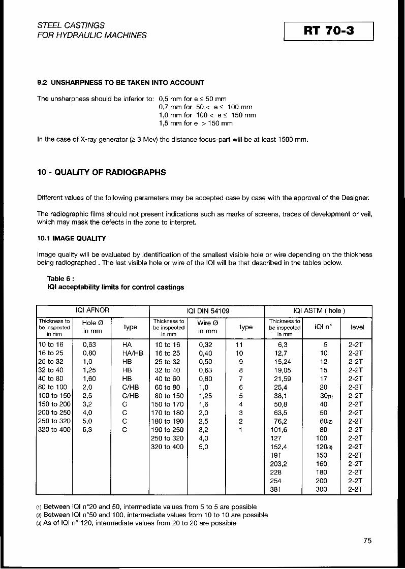
I STEEL CASTINGS I RT 70-3FOß HYDßAULlC MACHINES
9.2 UNSHARPNESS T 0 BE TAKEN INTO ACCOUNT
The unsharpness should be inferior to: 0,5 mm for e 5 50 mm 0,7 mm for 50 < e < 100 mm 1,0 mmfor 100< e < 150mm 1,5 mm for e > 150 mm
In the case of X-ray generator(23 MeV) the distance focus-Part will be at least 1500 mm.
10 - QUALITY OF RADIOGRAPHS
Different values of the following Parameters may be accepted case by case with the approval of the Designer.
The radiographic films should not present indications such as marks of screens, traces of development or veil, which may mask the defects in the zone to interpret.
10.1 IMAGE QUALITY
Image quality will be evalluated by identification of the smallest visible hole or wire depending on the thickness being radiographed . Thel last visible hole or wire of the IQI will be that described in the tables below.
Table 6 : IQIacceptability limitsfor control Castings
IQI AFNOR T IQI DIN 54109 T IQI ASTM ( hole ) Thickness to be inspected
in mm
Hole 0 in mm
Thickness to be inspected
in mm
Wire 0 in mm
Thickness to be inspected
in mrn IQI no level
10 to 16 HA 10 to 16 0,32 11 6 3 5 2-2T 16 to 25 HNHB 16 to 25 0,40 10 12,7 10 2-2T 25 to 32 HB 25 to 32 0,50 9 15,24 12 2-2T 32 to 40 HB 32 to 40 0,63 8 19,05 15 2-2T 40 to 80 HB 40 to 60 0,80 7 21,59 17 2-2T 30 to 100 C/H B 60 to 80 1,O 6 25,4 20 2-2T 100 to 150 C/H B 80 to 150 1,25 5 38,l 3 0 ~) 2-2T 150 to 200 C 150 to 170 1,6 4 50,8 40 2-2T 300 to 250 C 170 to 180 290 3 633 50 2-2T 250 to 320 C 180 to 190 2 3 2 76,2 60(2) 2-2T 320 to 400 C 190 to 250 3 2 1 101,6 80 2-2T
250 to 320 4,o 127 100 2-2T 320 to 400 5,o 1 52,4 120(3) 2-2T
191 150 2-2T 203,2 160 2-2T 228 180 2-2T 254 200 2-2T 381 300 2-2T
(1) Between IQI n"20 and $0, intermediate values from 5 to 5 are possible (2) Between IQI n"50 and100, intermediate values from 10 to 10 are possible (3)As of IQI no120, intermediate values from 20 to 20 are possible
75

I STEEL CASTINGS 1 RT 7013FOR HYDRAULIC MACHINES
Table 7 : IQI acceptability limits for controlof welds
IQI AFNOR T IQI DIN 54109 IQI ASTM ( hole ) 1 hickness to Thickness to Wire 0 Thickness to Hole 0be inspected
in mm in mm be inspected be inspected IQI no level in mm in mm in mm
10 to 16 0,50 HA 10 to 16 0,25 11 6 3 5 2-2T 16 to 25 0,63 HA 16 to 25 0,32 10 12,7 10 2-2T 25 to 32 0,80 HNHB 25 to 32 0,40 9 1524 12 2-2T 32 to 40 130 HNHB 32 to 40 0,50 8 19,05 15 2-2T 40 to 80 1,25 HB 40 to 60 0,63 7 21 3 9 17 2-2T 80 to 100 1,60 HB 60 to 80 0,80 6 25,4 20 2-2T 100 to 150 290 C/H B 80 to 150 190 5 38,l 3 0 ~ ) 2-2T 150 to 200 295 H B/C 150 to 170 1,25 4 50,8 40 2-2T 200 to 250 372 C 170 to 180 1,6 3 63,5 50 2-2T 250 to 320 4,o C 180 to 190 230 2 76,2 6 0 ~ ) 2-2T 320 to 400 5,O C 190 to 250 2 3 1 101,6 80 2-2T
250 to 320 3 2 127 100 2-2T 320 to 400 4,O 152,4 120(3) 2-2T
191 150 2-2T 203,2 160 2-2T 228 180 2-2T 254 200 2-2T 381 300 2-2T
In case of use ofIQI wires of the ASTM Standard, the level of quality obtained will have to correspond to that of the IQI with holes of this Same Standard. Other types of IQI could also be used. In general, one should attempt + to obtain sensitivity equal to 2 % for the inspection of the Castings and 1 3 % for the welds according to the formula :
diameter of the smallest visible hole or wireX 100S % = thickness
10.2 DENSIN The density of the exposed single or double films should be comprised between 2,O and 4 with a min. of1.3 per single film.The density may reach a reading of 4.5 if the illuminator allows. Density will be checked by means of a densitometer or by comparison with reference films. In case of great Variationof thickness, the density could be determined on films of adifferentspeed.Interpretation will be determined either in double or single film with the possibility of mixing films of different speeds while remaining in double film at a maximum.
10.3 DEVELOPMENT Filmdevelopmentmay be made manually orusingan automatic machine. The film development will be completed according to the manufacturer’s instructions.
Precautionsshould be taken to obtain a good fixing and a good washing of films to allow forproper conservation. Unless otherwise indicated, the films will be kept by the Company in Charge of their development +in a way to be able to interpret them. The Designer will specify at time of ordering the duration of archiving.
11 - ACCEPTANCECRlTERlA
The levels of acceptance may be different depending on the zones inspected (Castings, highly stressed areas, repaired or assembled parts by welding).
76

STEEL CASTINGS RT 70-3FOR HYDRAULIC MACHINES
11.1 FOR CASTINGS :
The films will be compared to reference films of the ASTM Standard, corresponding to the controlled thickness and to the source used. These ASTM reference negatives are:
-for thicknesses of less than51 mm : Standard E-446 -for thicknesses inclulded between 52 and 114 mm : Standard E-186 -for thicknesses inclulded between11 4 and 305 mm : Standard E-280 -for thicknesses greater than 305 mm, the Standard E-280 will be used unless specified otherwise.
The defects on these Standards are identifled by a letter, namely: type A indications : gas porosity
slagtype B indications : Sand and inclusion Example: 43, ) corresponds to a type C indications : shrinkage class 3 shrinkage
type D indications : Crack type E indications : hot tear type F indications : insert
For interpretation, one needs to determine the nature of the defect first, then compare the size and the density of the indications with those of the reference film ofthis Standard, for a surface corresponding to the reference surface of the Standard.
Table 8 : Admissible defects based on classes of acceptance
Level of severity as per ASTM classType of ASTM
indications Symbol :onsidered
I50 E 446 A l A2 A3 A4 A5 Gas A 6 0 B I114 E 186 A I A2 A3 A4 A5
porosity
I50 E 446 B1 B2 B3 B4 B5 Sand and ag inclusion B 50a5114 E I 8 6 B I
I
B2B4 I
B3 I I
B5
I50 E 446 Ccl: Cd1 Ca1 Cbl Cc2: Cd2 Ca2 Cb2 Cc3: Cd3 Ca3Cb3 Cc4,Cd4Ca4,Cb4 Ca5 9 Cb5
Shrinkage C
Hot tear D + E
Inserts I F are authorised wil:lh maxi length : 7 mm for thickness < 10 mm
2/3 of the thickness for thickness > 10 and < 100 mm 100 mm for thickness > 150 mm
(2) Core supports may be present, but they must be bondedto the meta1 without Crack at the surface of the part
77
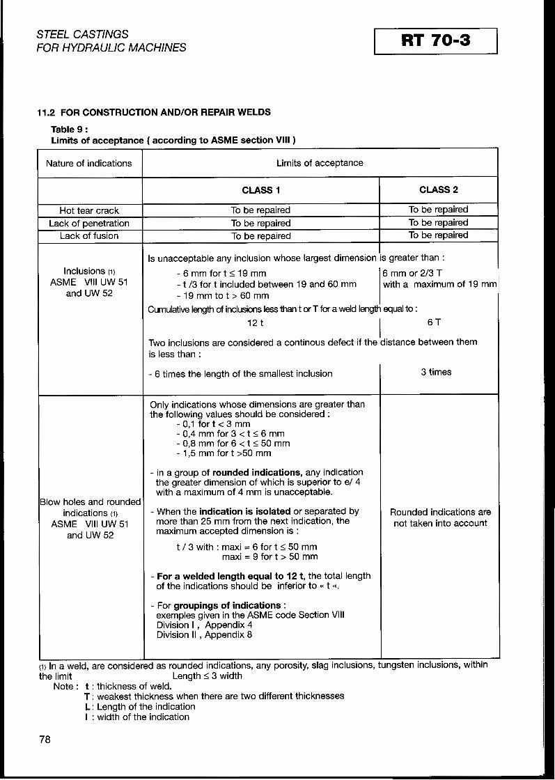
STEEL CASTINGS RT 7013FOR HYDRAULIC MACHINES
11.2 FOR CONSTRUCTION AND/OR REPAIR WELDS
Table 9 : Limits of acceptance ( according to ASME sectionVlll )
Nature of indications Limits of acceptance
CLASS 1 I CLASS 2 I
Hot tear Crack T0 be repaired T0 be repaired ______~~
Lack of penetration T0 be repaired I T0 be repaired Lack of fusion T0 be reDaired T0 be repaired
s unacceptable any inclusion whose largest dimension'is greater than : lnclusions (1) - 6 m m f o r t S 1 9 m m 6 mm or 2/3 T
ASME Vlll UW51 - t /3 for t included between 19 and 60 mm with a maximum of 19 mm and UW 52 - 1 9 m m t o t > 6 0 m m
Zumulative length of inclusions to :l e s s than t or T for a weld length equal 12 t 6 TI
Two inclusions are considered a continous defect if the distance between them is less than :
- 6 times the length of the smallest inclusion 3 times
Only indications whose dimensions are greater than the following values should be considered :
- 0,l for t < 3 mm - 0,4 mm for 3 < t I 6 mm - 0,8mm for 6 < t I 50 mm - 1,5 mm fort >50 mm
- in a group of rounded indications,any indication the greater dimension of which is Superior to e/ 4 with a maximum of4 mm is unacceptable.
llow holes and roundec indications (1) - When the indication is isolatedor separated by Rounded indications are
ASME Vlll UW 51 more than 25 mm from the next indication, the not taken into account and UW 52 maximum accepted dimension is :
t / 3 with : maxi = 6 for t I50 mm max i=9 fo r t>50mm
- For a welded length equal to 12 t, the total length of the indications should be inferior to t <<.
- For groupings of indications : exemples given in the ASME CodeSection Vlll Division I , Appendix 4 Division II ,Appendix 8
I I ____
(1) In a weld, are considered as rounded indications, any porosity, slag inclusions, tu ngsten inclusions, within the limit Length I3 width
Note : t : thickness of weld. T : weakest thickness when there are two different thicknesses L : Length of the indication I :width of the indication
78

STEEL CASTINGS RT 7013FOR HYDRAULIC MACHINES
The films on repairs will be identified by the letter R in addition to the identification already mentioned. The defects that are outside these criteria will be eliminated by grinding or gouging. They will be inspected again after repair. Unless otherwise specified, the weld repairs will be examined according to the criteria defined in Q11 . I .
12 - INSPECTION RIEPORT
The inspection report must indicate:
ldentification of the Founder, the Manufacturer or the Designer. ldentification of the part (heat Nr., traceability). Steel grade of the ca$ting. Designation of the examination documents used: Reference to the present specification, Quality Sheet. Stage of manufacture at inspection. Mode of surface preparation. Designation of films, SourCe, IQI, screens. Eamination conditionrs. Areas inspected. lnspection results. Name of the inspectar, his signature and his certification. ldentification of the firm in Charge of the inspection, if sub-contracted. Date of inspection and signature of the responsible Person for inspection.
79
