ccie routing and switching certification guide, fourth...
TRANSCRIPT


ii
CCIE Routing and Switching Certification Guide, Fourth EditionWendell Odom, CCIE No. 1624
Rus Healy, CCIE No. 15025
Denise Donohue, CCIE No. 9566
Copyright © 2010 Pearson Education, Inc.
Published by:Cisco Press800 East 96th Street Indianapolis, IN 46240 USA
All rights reserved. No part of this book may be reproduced or transmitted in any form or by any means, electronic or mechanical, including photocopying, recording, or by any information storage and retrieval system, without written permission from the publisher, except for the inclusion of brief quotations in a review.
Printed in the United States of America
First Printing November 2009
Library of Congress Cataloging-in-Publication Data
Odom, Wendell.
CCIE routing and switching exam certification guide / Wendell Odom, Rus Healy, Denise Donohue. -- 4th ed.
p. cm.
Includes index.
ISBN-13: 978-1-58705-980-3 (hardcover w/cd)
ISBN-10: 1-58705-980-0 (hardcover w/cd) 1. Telecommunications engineers—Certification—Study guides. 2. Routing (Computer network management)—Examinations—Study guides. 3. Telecommunication—Switching systems—Examinations—Study guides. 4. Computer networks—Examinations—Study guides. 5. Internetworking (Telecommunication)—Examinations—Study guides. I. Healy, Rus. II. Donohue, Denise. III. Title.
QA76.3.B78475 2010
004.6—dc22
2009041604
ISBN-13: 978-1-58705-980-3
ISBN-10: 1-58705-980-0
Warning and DisclaimerThis book is designed to provide information about Cisco CCIE Routing and Switching Written Exam, No. 350-001. Every effort has been made to make this book as complete and as accurate as possible, but no warranty or fitness is implied.
The information is provided on an “as is” basis. The authors, Cisco Press, and Cisco Systems, Inc. shall have neither liability nor responsibility to any person or entity with respect to any loss or damages arising from the information contained in this book or from the use of the discs or programs that may accompany it.
The opinions expressed in this book belong to the author and are not necessarily those of Cisco Systems, Inc.
Trademark AcknowledgmentsAll terms mentioned in this book that are known to be trademarks or service marks have been appropriately capital-ized. Cisco Press or Cisco Systems, Inc., cannot attest to the accuracy of this information. Use of a term in this book should not be regarded as affecting the validity of any trademark or service mark.

iii
Corporate and Government SalesCisco Press offers excellent discounts on this book when ordered in quantity for bulk purchases or special sales. For more information, please contact: U.S. Corporate and Government Sales1-800-382-3419 [email protected]
For sales outside of the U.S. please contact: International Sales1-317-581-3793 [email protected]
Feedback InformationAt Cisco Press, our goal is to create in-depth technical books of the highest quality and value. Each book is crafted with care and precision, undergoing rigorous development that involves the unique expertise of members from the pro-fessional technical community.
Readers’ feedback is a natural continuation of this process. If you have any comments regarding how we could improve the quality of this book, or otherwise alter it to better suit your needs, you can contact us through email at [email protected]. Please make sure to include the book title and ISBN in your message.
We greatly appreciate your assistance.
Publisher: Paul Boger
Associate Publisher: Dave Dusthimer
Cisco Representative: Erik Ullanderson
Cisco Press Program Manager: Anand Sundaram
Executive Editor: Brett Bartow
Managing Editor: Patrick Kanouse
Development Editor: Dayna Isley
Project Editor: Seth Kerney
Copy Editor: Keith Cline
Technical Editor(s): Maurilio Gorito, Narbik Kocharians
Editorial Assistant: Vanessa Evans
Book Designer: Louisa Adair
Composition: Mark Shirar
Indexer: Tim Wright
Proofreader: Apostrophe Editing Services
xxxi
ForewordCCIE Routing and Switching Exam Certification Guide, Fourth Edition, is an excellent self-study resource for the CCIE Routing and Switching written exam. Passing this exam is the first step to attaining the valued CCIE Routing and Switching certification and qualifies candidates for the CCIE Routing and Switching lab exam.
Gaining certification in Cisco technology is key to the continuing educational development of today’s networking professional. Through certification programs, Cisco validates the skills and expertise required to effectively manage the modern enterprise network.
Cisco Press Exam Certification Guides and preparation materials offer exceptional—and flexible—access to the knowledge and information required to stay current in your field of expertise or to gain new skills. Whether used as a supplement to more traditional training or as a primary source of learning, these materials offer users the information and knowledge validation required to gain new understanding and proficiencies.
Developed in conjunction with the Cisco certifications and training team, Cisco Press books are the only self-study books authorized by Cisco and offer students a series of exam practice tools and resource materials to help ensure that learners fully grasp the concepts and information presented.
Additional authorized Cisco instructor-led courses, e-learning, labs, and simulations are available exclusively from Cisco Learning Solutions Partners worldwide. To learn more, visit http://www.cisco.com/go/training.
I hope that you find these materials to be an enriching and useful part of your exam preparation.
Erik UllandersonManager, Global CertificationsLearning@CiscoOctober 2007
xxxii
IntroductionThe Cisco Certified Internetwork Expert (CCIE) certification may be the most challenging and prestigious of all networking certifications. It has received numerous awards and certainly has built a reputation as one of the most difficult certifications to earn in all of the technology world. Having a CCIE certification opens doors professionally typically results in higher pay and looks great on a resume.
Cisco currently offers several CCIE certifications. This book covers the version 4.0 exam blueprint topics of the written exam for the CCIE Routing and Switching certification. The following list details the currently available CCIE certifications at the time of this book’s publication; check http://www.cisco.com/go/ccie for the latest information. The certifications are listed in the order in which they were made available to the public:
■ CCIE Routing and Switching
■ CCIE Security
■ CCIE Service Provider
■ CCIE Voice
■ CCIE Storage Networking
■ CCIE Wireless
Each of the CCIE certifications requires the candidate to pass both a written exam and a one-day, hands-on lab exam. The written exam is intended to test your knowledge of theory, protocols, and configuration concepts that follow good design practices. The lab exam proves that you can configure and troubleshoot actual gear.
xxxiii
Why Should I Take the CCIE Routing and Switching Written Exam?
The first and most obvious reason to take the CCIE Routing and Switching written exam is that it is the first step toward obtaining the CCIE Routing and Switching certification. Also, you cannot schedule a CCIE lab exam until you pass the corresponding written exam. In short, if you want all the professional benefits of a CCIE Routing and Switching certification, you start by passing the written exam.
The benefits of getting a CCIE certification are varied, among which are the following:
■ Better pay
■ Career-advancement opportunities
■ Applies to certain minimum requirements for Cisco Silver and Gold Channel Partners, as well as those seeking Master Specialization, making you more valuable to Channel Partners
■ Better movement through the problem-resolution process when calling the Cisco TAC
■ Prestige
■ Credibility for consultants and customer engineers, including the use of the Cisco CCIE logo
The other big reason to take the CCIE Routing and Switching written exam is that it recertifies an individual’s associate-, professional-, and expert-level Cisco certifications. In other words, passing any CCIE written exam recertifies that person’s CCNA, CCNP, CCIP, CCSP, CCDP, and so on. (Recertification requirements do change, so please verify the requirements at http://www.cisco.com/go/certifications.)
xxxiv
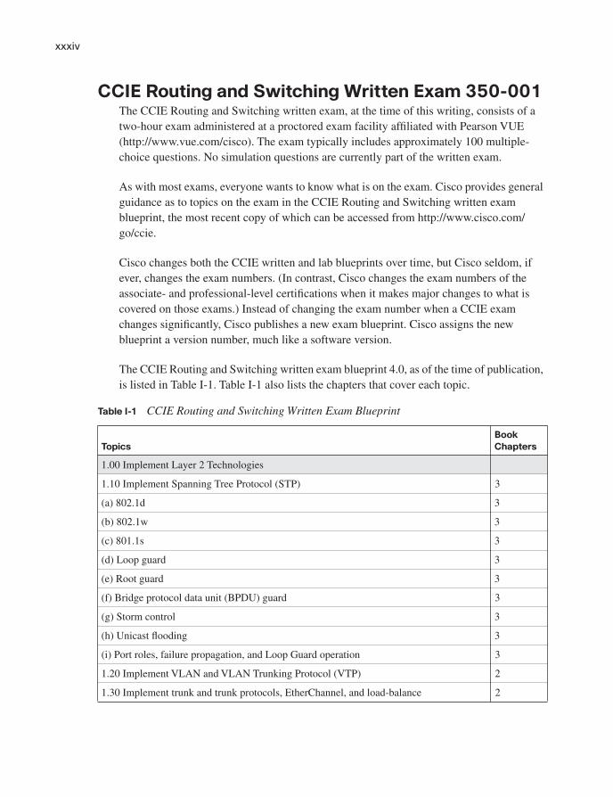
CCIE Routing and Switching Written Exam 350-001The CCIE Routing and Switching written exam, at the time of this writing, consists of a two-hour exam administered at a proctored exam facility affiliated with Pearson VUE (http://www.vue.com/cisco). The exam typically includes approximately 100 multiple-choice questions. No simulation questions are currently part of the written exam.
As with most exams, everyone wants to know what is on the exam. Cisco provides general guidance as to topics on the exam in the CCIE Routing and Switching written exam blueprint, the most recent copy of which can be accessed from http://www.cisco.com/go/ccie.
Cisco changes both the CCIE written and lab blueprints over time, but Cisco seldom, if ever, changes the exam numbers. (In contrast, Cisco changes the exam numbers of the associate- and professional-level certifications when it makes major changes to what is covered on those exams.) Instead of changing the exam number when a CCIE exam changes significantly, Cisco publishes a new exam blueprint. Cisco assigns the new blueprint a version number, much like a software version.
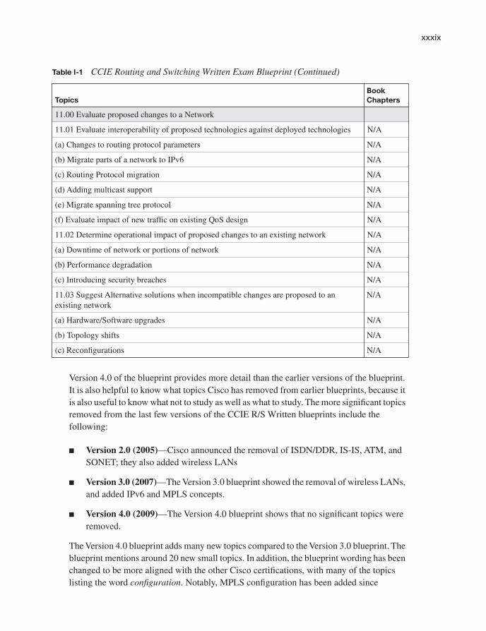
The CCIE Routing and Switching written exam blueprint 4.0, as of the time of publication, is listed in Table I-1. Table I-1 also lists the chapters that cover each topic.
Table I-1 CCIE Routing and Switching Written Exam Blueprint
Topics
Book
Chapters
1.00 Implement Layer 2 Technologies
1.10 Implement Spanning Tree Protocol (STP) 3
(a) 802.1d 3
(b) 802.1w 3
(c) 801.1s 3
(d) Loop guard 3
(e) Root guard 3
(f) Bridge protocol data unit (BPDU) guard 3
(g) Storm control 3
(h) Unicast flooding 3
(i) Port roles, failure propagation, and Loop Guard operation 3
1.20 Implement VLAN and VLAN Trunking Protocol (VTP) 2
1.30 Implement trunk and trunk protocols, EtherChannel, and load-balance 2

xxxv
1.40 Implement Ethernet technologies 1
(a) Speed and duplex 1
(b) Ethernet, Fast Ethernet, and Gigabit Ethernet 1
(c) PPP over Ethernet (PPPoE) 2
1.50 Implement Switched Port Analyzer (SPAN), Remote Switched Port Analyzer (RSPAN), and flow control
1
1.60 Implement Frame Relay 15
(a) Local Management Interface (LMI) 15
(b) Traffic shaping 15
(c) Full mesh 15
(d) Hub and spoke 15
(e) Discard eligible (DE) 15
1.70 Implement High-Level Data Link Control (HDLC) and PPP 15
2.00 Implement IPv4
2.10 Implement IP version 4 (IPv4) addressing, subnetting, and variable-length subnet masking (VLSM)
4
2.20 Implement IPv4 tunneling and Generic Routing Encapsulation (GRE) 6
2.30 Implement IPv4 RIP version 2 (RIPv2) E
2.40 Implement IPv4 Open Shortest Path First (OSPF) 8
(a) Standard OSPF areas 8
(b) Stub area 8
(c) Totally stubby area 8
(d) Not-so-stubby-area (NSSA) 8
(e) Totally NSSA 8
(f) Link-state advertisement (LSA) types 8
(g) Adjacency on a point-to-point and on a multi-access network 8
(h) OSPF graceful restart 8
2.50 Implement IPv4 Enhanced Interior Gateway Routing Protocol (EIGRP) 7
(a) Best path 7
(b) Loop-free paths 7
(c) EIGRP operations when alternate loop-free paths are available, and when they are not available
7
Table I-1 CCIE Routing and Switching Written Exam Blueprint (Continued)
Topics
Book
Chapters
continues

xxxvi
(d) EIGRP queries 7
(e) Manual summarization and autosummarization 9
(f) EIGRP stubs 7
2.60 Implement IPv4 Border Gateway Protocol (BGP) 10
(a) Next hop 10
(b) Peering 10
(c) Internal Border Gateway Protocol (IBGP) and External Border Gateway Protocol (EBGP)
10, 11
2.70 Implement policy routing 6
2.80 Implement Performance Routing (PfR) and Cisco Optimized Edge Routing (OER) 6
2.90 Implement filtering, route redistribution, summarization, synchronization, attributes, and other advanced
9, 11
3.00 Implement IPv6
3.10 Implement IP version 6 (IPv6) addressing and different addressing types 20
3.20 Implement IPv6 neighbor discovery 20
3.30 Implement basic IPv6 functionality protocols 20
3.40 Implement tunneling techniques 20
3.50 Implement OSPF version 3 (OSPFv3) 20
3.60 Implement EIGRP version 6 (EIGRPv6) 20
3.70 Implement filtering and route redistribution 20
4.00 Implement MPLS Layer 3 VPNs 19
4.10 Implement Multiprotocol Label Switching (MPLS) 19
4.20 Implement Layer 3 virtual private networks (VPNs) on provider edge (PE), provider (P), and customer edge (CE) routers
19
4.30 Implement virtual routing and forwarding (VRF) and Multi-VRF Customer Edge (VRF-Lite)
19
5.00 Implement IP Multicast
5.10 Implement Protocol Independent Multicast (PIM) sparse mode 16, 17
5.20 Implement Multicast Source Discovery Protocol (MSDP) 17
5.30 Implement interdomain multicast routing 17
5.40 Implement PIM Auto-Rendezvous Point (Auto-RP), unicast rendezvous point (RP), and bootstrap router (BSR)
17
Table I-1 CCIE Routing and Switching Written Exam Blueprint (Continued)
Topics
Book
Chapters

xxxvii
5.50 Implement multicast tools, features, and source-specific multicast 17
5.60 Implement IPv6 multicast, PIM, and related multicast protocols, such as Multicast Listener Discovery (MLD)
17
6.00 Implement Network Security
6.01 Implement access lists 18
6.02 Implement Zone Based Firewall 18
6.03 Implement Unicast Reverse Path Forwarding (uRPF) 18
6.04 Implement IP Source Guard 18
6.05 Implement authentication, authorization, and accounting (AAA) (configuring the AAA server is not required, only the client side (IOS) is configured)
18
6.06 Implement Control Plane Policing (CoPP) 18
6.07 Implement Cisco IOS Firewall 18
6.08 Implement Cisco IOS Intrusion Prevention System (IPS) 18
6.09 Implement Secure Shell (SSH) 18
6.10 Implement 802.1x 18
6.11 Implement NAT 18
6.12 Implement routing protocol authentication 18
6.13 Implement device access control 18
6.14 Implement security features 18
7.00 Implement Network Services
7.10 Implement Hot Standby Router Protocol (HSRP) 5
7.20 Implement Gateway Load Balancing Protocol (GLBP) 5
7.30 Implement Virtual Router Redundancy Protocol (VRRP) 5
7.40 Implement Network Time Protocol (NTP) 5
7.50 Implement DHCP 5
7.60 Implement Web Cache Communication Protocol (WCCP) 5
8.00 Implement Quality of Service (QoS)
8.10 Implement Modular QoS CLI (MQC) 12
(a) Network-Based Application Recognition (NBAR) 12
(b) Class-based weighted fair queuing (CBWFQ), modified deficit round robin (MDRR), and low latency queuing (LLQ)
13
(c) Classification 12
Table I-1 CCIE Routing and Switching Written Exam Blueprint (Continued)
Topics
Book
Chapters
continues

xxxviii
(d) Policing 14
(e) Shaping 14
(f) Marking 12
(g) Weighted random early detection (WRED) and random early detection (RED) 13
(h) Compression 15
8.20 Implement Layer 2 QoS: weighted round robin (WRR), shaped round robin (SRR), and policies
13
8.30 Implement link fragmentation and interleaving (LFI) for Frame Relay 15
8.40 Implement generic traffic shaping 14
8.50 Implement Resource Reservation Protocol (RSVP) 13
8.60 Implement Cisco AutoQoS 12
9.00 Troubleshoot a Network
9.10 Troubleshoot complex Layer 2 network issues 3
9.20 Troubleshoot complex Layer 3 network issues 9
9.30 Troubleshoot a network in response to application problems 14
9.40 Troubleshoot network services 6
9.50 Troubleshoot network security 18
10.00 Optimize the Network
10.01 Implement syslog and local logging 5
10.02 Implement IP Service Level Agreement SLA 5
10.03 Implement NetFlow 5
10.04 Implement SPAN, RSPAN, and router IP traffic export (RITE) 5
10.05 Implement Simple Network Management Protocol (SNMP) 5
10.06 Implement Cisco IOS Embedded Event Manager (EEM) 5
10.07 Implement Remote Monitoring (RMON) 5
10.08 Implement FTP 5
10.09 Implement TFTP 5
10.10 Implement TFTP server on router 5
10.11 Implement Secure Copy Protocol (SCP) 5
10.12 Implement HTTP and HTTPS 5
10.13 Implement Telnet 5
Table I-1 CCIE Routing and Switching Written Exam Blueprint (Continued)
Topics
Book
Chapters
xxxix
Version 4.0 of the blueprint provides more detail than the earlier versions of the blueprint. It is also helpful to know what topics Cisco has removed from earlier blueprints, because it is also useful to know what not to study as well as what to study. The more significant topics removed from the last few versions of the CCIE R/S Written blueprints include the following:
■ Version 2.0 (2005)—Cisco announced the removal of ISDN/DDR, IS-IS, ATM, and SONET; they also added wireless LANs
■ Version 3.0 (2007)—The Version 3.0 blueprint showed the removal of wireless LANs, and added IPv6 and MPLS concepts.
■ Version 4.0 (2009)—The Version 4.0 blueprint shows that no significant topics were removed.
The Version 4.0 blueprint adds many new topics compared to the Version 3.0 blueprint. The blueprint mentions around 20 new small topics. In addition, the blueprint wording has been changed to be more aligned with the other Cisco certifications, with many of the topics listing the word configuration. Notably, MPLS configuration has been added since
11.00 Evaluate proposed changes to a Network
11.01 Evaluate interoperability of proposed technologies against deployed technologies N/A
(a) Changes to routing protocol parameters N/A
(b) Migrate parts of a network to IPv6 N/A
(c) Routing Protocol migration N/A
(d) Adding multicast support N/A
(e) Migrate spanning tree protocol N/A
(f) Evaluate impact of new traffic on existing QoS design N/A
11.02 Determine operational impact of proposed changes to an existing network N/A
(a) Downtime of network or portions of network N/A
(b) Performance degradation N/A
(c) Introducing security breaches N/A
11.03 Suggest Alternative solutions when incompatible changes are proposed to an existing network
N/A
(a) Hardware/Software upgrades N/A
(b) Topology shifts N/A
(c) Reconfigurations N/A
Table I-1 CCIE Routing and Switching Written Exam Blueprint (Continued)
Topics
Book
Chapters

xl
Version 3.0, with several of the small topics, ranging in one to three pages of coverage in the book, also now including some configuration discussion.
The Version 4.0 blueprint also now includes five troubleshooting topics, as listed in section 9.0 of the blueprint, and paraphrased as follows:
■ LANs
■ IP routing
■ Application performance (QoS)
■ Network services
■ Security
The existence of specific topics for troubleshooting may be a bit confusing at first, because the CCIE lab also now contains a specific troubleshooting component. However, the prior versions of the CCIE written exam already included questions asked in the context of a broken network or misconfigured device. These new blueprint items simply formalize the idea that you should not only understand proper configuration, but be able to predict what will happen when problems occur.
Finally, the other big change between the Version 3.0 and Version 4.0 blueprint relates to section 11.0 of the blueprint. This new section might be better termed “Dealing with issues that arise in real life when networks change.” Section 11.0, actually titled “Evaluate Proposed Changes to a Network,” diverges from the usual convention of a list of specific technologies. Instead, section 11.0 lists topics about how engineers do their jobs. Specifically, these topics relate to issues that arise when implementing network technologies in an existing network—topics that can be well learned by doing a network engineering job, and questions that can be answered by applying the vast amount of information covered through the whole book. From one perspective, the whole book already covers the topics in this section, but there is no specific section of the printed book that addresses these topics.
To give you practice on these topics, and pull the topics together, Edition 4 of the CCIERouting and Switching Exam Certification Guide includes a large set of CD questions that mirror the types of questions expected for part 11 of the Version 4.0 blueprint. By their very nature, these topics require the application of the knowledge listed throughout the book. This special section of questions provides a means to learn and practice these skills with a proportionally larger set of questions added specifically for this purpose.
These questions will be available to you in the practice test engine database, whether you take full exams or choose questions by category.

xli
About the CCIE Routing and Switching Official Exam Certification Guide, Fourth Edition
This section provides a brief insight into the contents of the book, the major goals, and some of the book features that you will encounter when using this book.
Book OrganizationThis book contains nine major parts. The book places the longer and the more long-lived topics earlier in the book. For example, the most familiar topics, LAN switching and IPv4 routing, occupy the first three parts, and consume more than 400 pages of the book. QoS, which has been a part of the blueprint for a long times, follows as part IV.
Beyond the chapters in the nine major parts of the book, you will find several useful appendixes gathered in Part X.
Following is a description of each part’s coverage:
■ Part I, “LAN Switching” (Chapters 1–3)
This part focuses on LAN Layer 2 features, specifically Ethernet (Chapter 1), VLANs and trunking (Chapter 2), and Spanning Tree Protocol (Chapter 3).
■ Part II, “IP” (Chapters 4–5)
This part is titled “IP” to match the blueprint, but it might be better titled “TCP/IP” because it covers details across the spectrum of the TCP/IP protocol stack. It includes IP addressing (Chapter 4) and IP services such as DHCP and ARP (Chapter 5).
■ Part III, “IP Routing” (Chapters 6–11)
This part covers some of the more important topics on the exam and is easily the largest part of the book. It covers Layer 3 forwarding concepts (Chapter 6), followed by two routing protocol chapters, one each about EIGRP and OSPF (Chapters 7 and 8, respectively). (Note that while RIP Version 2 is listed in the blueprint, its role is waning; therefore, that material exists in this book as CD-only Appendix E.) Following that, Chapter 9 covers route redistribution between IGPs. At the end, Chapter 10 hits the details of BGP, with Chapter 11 looking at BGP path attributes and how to influence BGP’s choice of best path.
■ Part IV, “QoS” (Chapters 12–14)
This part covers the more popular QoS tools, including some MQC-based tools, as well as several older tools, particularly FRTS. The chapters include coverage of classification and marking (Chapter 12), queuing and congestion avoidance (Chapter 13), plus shaping, policing, and link efficiency (Chapter 14).
xlii
■ Part V, “Wide-Area Networks” (Chapter 15)
The WAN coverage has been shrinking over the last few revisions to the CCIE R&S written exam. Chapter 15 includes some brief coverage of PPP and Frame Relay. Note that the previous version (V3.0) and current version (V4.0) of the blueprint includes another WAN topic, MPLS, which is covered in Part VIII, Chapter 19.
■ Part VI, “IP Multicast” (Chapters 16–17)
Chapter 16 covers multicast on LANs, including IGMP and how hosts join multicast groups. Chapter 17 covers multicast WAN topics.
■ Part VII, “Security” (Chapter 18)
Given the CCIE tracks for both Security and Voice, Cisco has a small dilemma regarding whether to cover those topics on CCIE Routing and Switching, and if so, in how much detail. This part covers a variety of security topics appropriate for CCIE Routing and Switching, in a single chapter. This chapter focuses on switch and router security.
■ Part VIII, “MPLS” (Chapter 19)
As mentioned in the WAN section, the CCIE R&S exam’s coverage of MPLS has been growing over the last two versions of the blueprint. This chapter focuses on enterprise-related topics such as core MPLS concepts and MPLS VPNs, including basic configuration.
■ Part IX, “IP Version 6” (Chapter 20)
Chapter 20 examines a wide variety of IPv6 topics, including addressing, routing protocols, redistribution, and coexistence.
■ Part X, “Appendixes”
Appendix A, “Answers to the ‘Do I Know This Already?’ Quizzes”
This appendix lists answers and explanations for the questions at the beginning of each chapter.
Appendix B, “Decimal to Binary Conversion Table”
This appendix lists the decimal values 0 through 255, with their binary equivalents.
Appendix C, “CCIE Routing and Switching Exam Updates: Version 1.0”
As of the first printing of the book, this appendix contains only a few words that reference the web page for this book at http://www.ciscopress.com/title/9781587059803. As the blueprint

xliii
evolves over time, the authors will post new materials at the website. Any future printings of the book will include the latest newly added materials in printed form inside Appendix C. If Cisco releases a major exam update, changes to the book will be available only in a new edition of the book and not on this site.
(CD-only) Appendix D, “IP Addressing Practice”
This appendix lists several practice problems for IP subnetting and finding summary routes. The explanations to the answers use the shortcuts described in the book.
(CD-only) Appendix E, “RIP Version 2”
This appendix lists a copy of the RIP Version 2 chapter from the previous edition of this book.
(CD-only) Appendix F, “IGMP”
This short appendix contains background information on Internet Group Management Protocol (IGMP) that was in the previous edition’s first multicast chapter. It is included in case the background information might be useful to some readers.
(CD-only) Appendix G, “Key Tables for CCIE Study”
This appendix lists the most important tables from the core chapters of the book. The tables have much of the content removed so that you can use them as an exercise. You can print the PDF and then fill in the table from memory, checking your answers against the completed tables in Appendix H.
(CD-only) Glossary
The Glossary contains the key terms listed in the book.
Book FeaturesThe core chapters of this book have several features that help you make the best use of your time:
■ “Do I Know This Already?” Quizzes—Each chapter begins with a quiz that helps you to determine the amount of time you need to spend studying that chapter. If you score yourself strictly, and you miss only one question, you may want to skip the core
NOTE Appendixes D through H and the Glossary are in printable, PDF format on the CD.

xliv
of the chapter and move on to the “Foundation Summary” section at the end of the chapter, which lets you review facts and spend time on other topics. If you miss more than one, you may want to spend some time reading the chapter or at least reading sections that cover topics about which you know you are weaker.
■ Foundation Topics—These are the core sections of each chapter. They explain the protocols, concepts, and configuration for the topics in that chapter.
■ Foundation Summary—The “Foundation Summary” section of this book departs from the typical features of the “Foundation Summary” section of other Cisco Press Exam Certification Guides. This section does not repeat any details from the “Foundation Topics” section; instead, it simply summarizes and lists facts related to the chapter but for which a longer or more detailed explanation is not warranted.
■ Key topics—Throughout the “Foundation Topics” section, a Key Topic icon has been placed beside the most important areas for review. After reading a chapter, when doing your final preparation for the exam, take the time to flip through the chapters, looking for the Key Topic icons, and review those paragraphs, tables, figures, and lists.
■ Fill In Key Tables from Memory—The more important tables from the chapters have been copied to PDF files available on the CD as Appendix G. The tables have most of the information removed. After printing these mostly empty tables, you can use them to improve your memory of the facts in the table by trying to fill them out. This tool should be useful for memorizing key facts. That same CD-only appendix contains the completed tables so you can check your work.
■ CD-based practice exam—The companion CD contains multiple-choice questions and a testing engine. The CD includes 200 questions unique to the CD. As part of your final preparation, you should practice with these questions to help you get used to the exam-taking process, as well as help refine and prove your knowledge of the exam topics.
■ Special question section for the “Implement Proposed Changes to a Network” section of the Blueprint—To provide practice and perspectives on these exam topics, a special section of questions has been developed to help you both prepare for these new types of questions.
xlv
■ Key terms and Glossary—The more important terms mentioned in each chapter are listed at the end of each chapter under the heading “Definitions.” The Glossary, found on the CD that comes with this book, lists all the terms from the chapters. When studying each chapter, you should review the key terms, and for those terms about which you are unsure of the definition, you can review the short definitions from the Glossary.
■ Further Reading—Most chapters include a suggested set of books and websites for additional study on the same topics covered in that chapter. Often, these references will be useful tools for preparation for the CCIE Routing and Switching lab exam.
C H A P T E R 2
Virtual LANs and VLAN Trunking
This chapter continues with the coverage of some of the most fundamental and important LAN topics with coverage of VLANs and VLAN trunking. As usual, for those of you current in your knowledge of the topics in this chapter, review the items next to the Key Topic icons spread throughout the chapter, plus the “Foundation Summary” and “Memory Builders” sections at the end of the chapter.
“Do I Know This Already?” Quiz
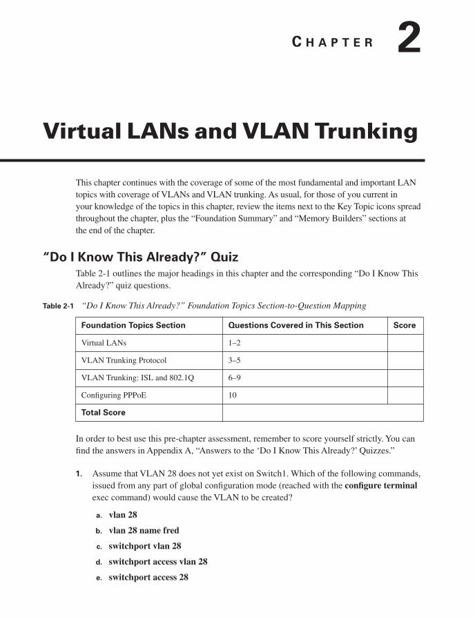
Table 2-1 outlines the major headings in this chapter and the corresponding “Do I Know This Already?” quiz questions.
In order to best use this pre-chapter assessment, remember to score yourself strictly. You can find the answers in Appendix A, “Answers to the ‘Do I Know This Already?’ Quizzes.”
1. Assume that VLAN 28 does not yet exist on Switch1. Which of the following commands, issued from any part of global configuration mode (reached with the configure terminalexec command) would cause the VLAN to be created?
a. vlan 28
b. vlan 28 name fred
c. switchport vlan 28
d. switchport access vlan 28
e. switchport access 28
Table 2-1 “Do I Know This Already?” Foundation Topics Section-to-Question Mapping
Foundation Topics Section Questions Covered in This Section Score
Virtual LANs 1–2
VLAN Trunking Protocol 3–5
VLAN Trunking: ISL and 802.1Q 6–9
Configuring PPPoE 10
Total Score

32 Chapter 2: Virtual LANs and VLAN Trunking
2. Which of the following are the two primary motivations for using private VLANs?
a. Better LAN security
b. IP subnet conservation
c. Better consistency in VLAN configuration details
d. Reducing the impact of broadcasts on end-user devices
e. Reducing the unnecessary flow of frames to switches that do not have any ports in the
VLAN to which the frame belongs
3. Which of the following VLANs can be pruned by VTP on an 802.1Q trunk?
a. 1–1023
b. 1–1001
c. 2–1001
d. 1–1005
e. 2–1005
4. An existing switched network has ten switches, with Switch1 and Switch2 being the only VTP servers in the network. The other switches are all VTP clients and have successfully learned about the VLANs from the VTP servers. The only configured VTP parameter on all switches is the VTP domain name (Larry). The VTP revision number is 201. What happens when a new, already-running VTP client switch, named Switch11, with domain name Larry and revision number 301, connects via a trunk to any of the other ten switches?
a. No VLAN information changes; Switch11 ignores the VTP updates sent from the two existing VTP servers until the revision number reaches 302.
b. The original ten switches replace their old VLAN configuration with the configuration in Switch11.
c. Switch11 replaces its own VLAN configuration with the configuration sent to it by one of the original VTP servers.
d. Switch11 merges its existing VLAN database with the database learned from the VTP servers, because Switch11 had a higher revision number.
“Do I Know This Already?” Quiz 33
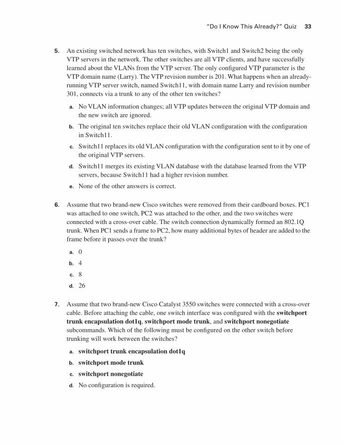
5. An existing switched network has ten switches, with Switch1 and Switch2 being the only VTP servers in the network. The other switches are all VTP clients, and have successfully learned about the VLANs from the VTP server. The only configured VTP parameter is the VTP domain name (Larry). The VTP revision number is 201. What happens when an already-running VTP server switch, named Switch11, with domain name Larry and revision number 301, connects via a trunk to any of the other ten switches?
a. No VLAN information changes; all VTP updates between the original VTP domain and the new switch are ignored.
b. The original ten switches replace their old VLAN configuration with the configuration in Switch11.
c. Switch11 replaces its old VLAN configuration with the configuration sent to it by one of the original VTP servers.
d. Switch11 merges its existing VLAN database with the database learned from the VTP servers, because Switch11 had a higher revision number.
e. None of the other answers is correct.
6. Assume that two brand-new Cisco switches were removed from their cardboard boxes. PC1 was attached to one switch, PC2 was attached to the other, and the two switches were connected with a cross-over cable. The switch connection dynamically formed an 802.1Q trunk. When PC1 sends a frame to PC2, how many additional bytes of header are added to the frame before it passes over the trunk?
a. 0
b. 4
c. 8
d. 26
7. Assume that two brand-new Cisco Catalyst 3550 switches were connected with a cross-over cable. Before attaching the cable, one switch interface was configured with the switchporttrunk encapsulation dot1q, switchport mode trunk, and switchport nonegotiatesubcommands. Which of the following must be configured on the other switch before trunking will work between the switches?
a. switchport trunk encapsulation dot1q
b. switchport mode trunk
c. switchport nonegotiate
d. No configuration is required.

34 Chapter 2: Virtual LANs and VLAN Trunking
8. When configuring trunking on a Cisco router fa0/1 interface, under which configuration modes could the IP address associated with the native VLAN (VLAN 1 in this case) be configured?
a. Interface fa 0/1 configuration mode
b. Interface fa 0/1.1 configuration mode
c. Interface fa 0/1.2 configuration mode
d. None of the other answers is correct
9. Which of the following is false about 802.1Q?
a. Encapsulates the entire frame inside an 802.1Q header and trailer
b. Supports the use of a native VLAN
c. Allows VTP to operate only on extended-range VLANs
d. Is chosen over ISL by DTP
10. Which command enables PPPoE on the outside Ethernet interface on a Cisco router?
a. pppoe enable
b. pppoe-client enable
c. pppoe-client dialer-pool-number
d. pppoe-client dialer-number
Virtual LANs 35
Foundation Topics
Virtual LANs
In an Ethernet LAN, a set of devices that receive a broadcast sent by any one of the devices in the same set is called a broadcast domain. On switches that have no concept of virtual LANs (VLAN), a switch simply forwards all broadcasts out all interfaces, except the interface on which it received the frame. As a result, all the interfaces on an individual switch are in the same broadcast domain. Also, if the switch connects to other switches and hubs, the interfaces on those switches and hubs are also in the same broadcast domain.
A VLAN is simply an administratively defined subset of switch ports that are in the same broadcast domain. Ports can be grouped into different VLANs on a single switch, and on multiple interconnected switches as well. By creating multiple VLANs, the switches create multiple broadcast domains. By doing so, a broadcast sent by a device in one VLAN is forwarded to the other devices in that same VLAN; however, the broadcast is not forwarded to devices in the other VLANs.
With VLANs and IP, best practices dictate a one-to-one relationship between VLANs and IP subnets. Simply put, the devices in a single VLAN are typically also in the same single IP subnet. Alternately, it is possible to put multiple subnets in one VLAN, and use secondary IP addresses on routers to route between the VLANs and subnets. Also, although not typically done, you can design a network to use one subnet on multiple VLANs, and use routers with proxy ARP enabled to forward traffic between hosts in those VLANs. (Private VLANs might be considered to consist of one subnet over multiple VLANs as well, as covered later in this chapter.) Ultimately, the CCIE written exams tend to focus more on the best use of technologies, so this book will assume that one subnet sits on one VLAN, unless otherwise stated.
Layer 2 switches forward frames between devices in the same VLAN, but they do not forward frames between two devices in different VLANs. To forward data between two VLANs, a multilayer switch (MLS) or router is needed. Chapter 6, “IP Forwarding (Routing),” covers the details of MLS.
VLAN ConfigurationConfiguring VLANs in a network of Cisco switches requires just a few simple steps:
Step 1 Create the VLAN itself.
Step 2 Associate the correct ports with that VLAN.

36 Chapter 2: Virtual LANs and VLAN Trunking
The challenge relates to how some background tasks differ depending on how the Cisco VLANTrunking Protocol (VTP) is configured, and whether normal-range or extended-range VLANs are being used.
Using VLAN Database Mode to Create VLANs
To begin, consider Example 2-1, which shows some of the basic mechanics of VLAN creation in VLAN database configuration mode. VLAN database configuration mode allows the creation of VLANs, basic administrative settings for each VLAN, and verification of VTP configuration information. Only normal-range (VLANs 1–1005) VLANs can be configured in this mode, and the VLAN configuration is stored in a Flash file called vlan.dat.
Example 2-1 demonstrates VLAN database configuration mode, showing the configuration on Switch3 from Figure 2-1. The example shows VLANs 21 and 22 being created.
Figure 2-1 Simple Access and Distribution
Example 2-1 VLAN Creation in VLAN Database Mode–Switch3
! Below, note that FA 0/12 and FA0/24 missing from the list, because they have
! dynamically become trunks, supporting multiple VLANs.
Switch3# sssshhhhoooowwww vvvvllllaaaannnn bbbbrrrriiiieeeeffff
VLAN Name Status Ports
---- -------------------------------- --------- -------------------------------
1 default active Fa0/1, Fa0/2, Fa0/3, Fa0/4
Fa0/5, Fa0/6, Fa0/7, Fa0/8
Fa0/9, Fa0/10, Fa0/11, Fa0/13
Fa0/14, Fa0/15, Fa0/16, Fa0/17
Fa0/18, Fa0/19, Fa0/20, Fa0/21
Fa0/22, Fa0/23
PC1
SW1
R3
Fa0/0 Gi0/1
R1
VLAN 21Subnet 10.1.21.x/24
VLAN 22Subnet 10.1.22.x/24
Fa0/2
R2
R4
Fa0/7
Fa0/12 Fa0/24
Fa0/3
Fa0/1
SW3
SW2
Fa0/5
SW4

Virtual LANs 37
! Below, “unsup” means that this 2950 switch does not support FDDI and TR
1002 fddi-default act/unsup
1003 token-ring-default act/unsup
1004 fddinet-default act/unsup
1005 trnet-default act/unsup
! Below, vvvvllllaaaannnn ddddaaaattttaaaabbbbaaaasssseeee moves user to VLAN database configuration mode.
! The vvvvllllaaaannnn 22221111 command defines the VLAN, as seen in the next command output
! (sssshhhhoooowwww ccccuuuurrrrrrrreeeennnntttt), VLAN 21 is not in the “current” VLAN list.
Switch3# vvvvllllaaaannnn ddddaaaattttaaaabbbbaaaasssseeee
Switch3(vlan)# vvvvllllaaaannnn 22221111
VLAN 21 added:
Name: VLAN0021
! The sssshhhhoooowwww ccccuuuurrrrrrrreeeennnntttt command lists the VLANs available to the IOS when the switch
! is in VTP Server mode. The command lists the VLANs in numeric order, with
! VLAN 21 missing.
Switch3(vlan)# sssshhhhoooowwww ccccuuuurrrrrrrreeeennnntttt
VLAN ISL Id: 1
Name: default
Media Type: Ethernet
VLAN 802.10 Id: 100001
State: Operational
MTU: 1500
Backup CRF Mode: Disabled
Remote SPAN VLAN: No
VLAN ISL Id: 1002
Name: fddi-default
Media Type: FDDI
VLAN 802.10 Id: 101002
State: Operational
MTU: 1500
Backup CRF Mode: Disabled
Remote SPAN VLAN: No
! Lines omitted for brevity
! Next, note that sssshhhhoooowwww pppprrrrooooppppoooosssseeeedddd lists VLAN 21. The vvvvllllaaaannnn 22221111 command
! creates the definition, but it must be “applied” before it is “current”.
Switch3(vlan)# sssshhhhoooowwww pppprrrrooooppppoooosssseeeedddd
VLAN ISL Id: 1
Name: default
Media Type: Ethernet
VLAN 802.10 Id: 100001
State: Operational
MTU: 1500
Backup CRF Mode: Disabled
Remote SPAN VLAN: No
continues
Example 2-1 VLAN Creation in VLAN Database Mode–Switch3 (Continued)

38 Chapter 2: Virtual LANs and VLAN Trunking
Using Configuration Mode to Put Interfaces into VLANs
To make a VLAN operational, the VLAN must be created, and then switch ports must be assigned to the VLAN. Example 2-2 shows how to associate the interfaces with the correct VLANs, once again on Switch3.
VLAN ISL Id: 21
Name: VLAN0021
Media Type: Ethernet
VLAN 802.10 Id: 100021
State: Operational
MTU: 1500
Backup CRF Mode: Disabled
Remote SPAN VLAN: No
! Lines omitted for brevity
! Next, you could aaaappppppppllllyyyy to complete the addition of VLAN 21,
! aaaabbbboooorrrrtttt to not make the changes and exit VLAN database mode, or
! rrrreeeesssseeeetttt to not make the changes but stay in VLAN database mode.
Switch3(vlan)# ????
VLAN database editing buffer manipulation commands:
abort Exit mode without applying the changes
apply Apply current changes and bump revision number
exit Apply changes, bump revision number, and exit mode
no Negate a command or set its defaults
reset Abandon current changes and reread current database
show Show database information
vlan Add, delete, or modify values associated with a single VLAN
vtp Perform VTP administrative functions.
! The aaaappppppppllllyyyy command was used, making the addition of VLAN 21 complete.
Switch3(vlan)# aaaappppppppllllyyyy
APPLY completed.
! A sssshhhhoooowwww ccccuuuurrrrrrrreeeennnntttt now would list VLAN 21.
Switch3(vlan)# vvvvllllaaaannnn 22222222 nnnnaaaammmmeeee cccccccciiiieeee----vvvvllllaaaannnn----22222222
VLAN 22 added:
Name: ccie-vlan-22
! Above and below, some variations on commands are shown, along with the
! creation of VLAN 22, with name ccie-vlan-22.
! Below, the vvvvllllaaaannnn 22222222 option is used on sssshhhhoooowwww ccccuuuurrrrrrrreeeennnntttt and sssshhhhoooowwww pppprrrrooooppppoooosssseeeedddd
! detailing the fact that the apply has not been done yet.
Switch3(vlan)# sssshhhhoooowwww ccccuuuurrrrrrrreeeennnntttt 22222222
VLAN 22 does not exist in current database
Switch3(vlan)# sssshhhhoooowwww pppprrrrooooppppoooosssseeeedddd 22222222
VLAN ISL Id: 22
! Lines omitted for brevity
! Finally, the user exits VLAN database mode using CTRL-Z, which does
! nnnnooootttt inherently apply the change. CTRL-Z actually executes an aaaabbbboooorrrrtttt.
Switch3(vlan)# ^̂̂̂ZZZZ
Example 2-1 VLAN Creation in VLAN Database Mode–Switch3 (Continued)

Virtual LANs 39
Using Configuration Mode to Create VLANs
At this point, the two new VLANs (21 and 22) have been created on Switch3, and the two interfaces are now in the correct VLANs. However, Cisco IOS switches support a different way to create VLANs, using configuration mode, as shown in Example 2-3.
NOTE At the end of Example 2-1, VLAN 22 had not been successfully created. The assumption for Example 2-2 is that VLAN 22 has been successfully created.
Example 2-2 Assigning Interfaces to VLANs–Switch3
! First, the sssswwwwiiiittttcccchhhhppppoooorrrrtttt aaaacccccccceeeessssssss command assigns the VLAN numbers to the
! respective interfaces.
Switch3# ccccoooonnnnffffiiiigggg tttt
Enter configuration commands, one per line. End with CNTL/Z.
Switch3(config)# iiiinnnntttt ffffaaaa 0000////3333
Switch3(config-if)# sssswwwwiiiittttcccchhhhppppoooorrrrtttt aaaacccccccceeeessssssss vvvvllllaaaannnn 22222222
Switch3(config-if)# iiiinnnntttt ffffaaaa 0000////7777
Switch3(config-if)# sssswwwwiiiittttcccchhhhppppoooorrrrtttt aaaacccccccceeeessssssss vvvvllllaaaannnn 22221111
Switch3(config-if)# ^̂̂̂ZZZZ
! Below, sssshhhhoooowwww vvvvllllaaaannnn bbbbrrrriiiieeeeffff lists these same two interfaces as now being in
! VLANs 21 and 22, respectively.
Switch3# sssshhhhoooowwww vvvvllllaaaannnn bbbbrrrriiiieeeeffff
VLAN Name Status Ports
---- -------------------------------- --------- -------------------------------
1 default active Fa0/1, Fa0/2, Fa0/4, Fa0/5
Fa0/6, Fa0/8, Fa0/9, Fa0/10
Fa0/11, Fa0/13, Fa0/14, Fa0/15
Fa0/16, Fa0/17, Fa0/18, Fa0/19
Fa0/20, Fa0/21, Fa0/22, Fa0/23
21 VLAN0021 active Fa0/7
22 ccie-vlan-22 active Fa0/3
! Lines omitted for brevity
! While the VLAN configuration is not shown in the running-config at this point,
! the sssswwwwiiiittttcccchhhhppppoooorrrrtttt aaaacccccccceeeessssssss command that assigns the VLAN for the interface is in the
! configuration, as seen with the sssshhhhoooowwww rrrruuuunnnn iiiinnnntttt ffffaaaa 0000////3333 command.
Switch3# sssshhhhoooowwww rrrruuuunnnn iiiinnnntttt ffffaaaa 0000////3333
interface FastEthernet0/3
switchport access vlan 22
Example 2-3 Creating VLANs in Configuration Mode–Switch3
! First, VLAN 31 did not exist when the sssswwwwiiiittttcccchhhhppppoooorrrrtttt aaaacccccccceeeessssssss vvvvllllaaaannnn 33331111 command was
! issued. As a result, the switch both created the VLAN and put iiiinnnntttteeeerrrrffffaaaacccceeee ffffaaaa0000////8888
! into that VLAN. Then, the vvvvllllaaaannnn 33332222 global command was used to create a
continues

40 Chapter 2: Virtual LANs and VLAN Trunking
Example 2-3 shows how the switchport access vlan subcommand creates the VLAN, as needed, and assigns the interface to that VLAN. Note that in Example 2-3, the show vlan brief output lists fa0/8 as being in VLAN 31. Because no ports have been assigned to VLAN 32 as of yet, the final line in Example 2-3 simply does not list any interfaces.
The VLAN creation process is simple but laborious in a large network. If many VLANs exist, and they exist on multiple switches, instead of manually configuring the VLANs on each switch, you can use VTP to distribute the VLAN configuration of a VLAN to the rest of the switches. VTP will be discussed after a brief discussion of private VLANs.
Private VLANsEngineers may design VLANs with many goals in mind. In many cases today, devices end up in the same VLAN just based on the physical locations of the wiring drops. Security is another motivating factor in VLAN design: devices in different VLANs do not overhear each other’s
! VLAN from configuration mode, and the nnnnaaaammmmeeee subcommand was used to assign a
! non-default name.
Switch3# ccccoooonnnnffff tttt
Enter configuration commands, one per line. End with CNTL/Z.
Switch3(config)# iiiinnnntttt ffffaaaa 0000////8888
Switch3(config-if)# sssswwwwiiiittttcccchhhhppppoooorrrrtttt aaaacccccccceeeessssssss vvvvllllaaaannnn 33331111
% Access VLAN does not exist. Creating vlan 31
Switch3(config-if)# eeeexxxxiiiitttt
Switch3(config)# vvvvllllaaaannnn 33332222
Switch3(config-vlan)# nnnnaaaammmmeeee cccccccciiiieeee----vvvvllllaaaannnn----33332222
Switch3(config-vlan)# ^̂̂̂ZZZZ
Switch3# sssshhhhoooowwww vvvvllllaaaannnn bbbbrrrriiiieeeeffff
VLAN Name Status Ports
---- -------------------------------- --------- -------------------------------
1 default active Fa0/1, Fa0/2, Fa0/4, Fa0/5
Fa0/6, Fa0/9, Fa0/10, Fa0/11
Fa0/13, Fa0/14, Fa0/15, Fa0/16
Fa0/17, Fa0/18, Fa0/19, Fa0/20
Fa0/21, Fa0/22, Fa0/23
21 VLAN0021 active Fa0/7
22 ccie-vlan-22 active Fa0/3
31 VLAN0031 active Fa0/8
32 ccie-vlan-32 active
! Portions omitted for brevity
Example 2-3 Creating VLANs in Configuration Mode–Switch3 (Continued)
Virtual LANs 41
broadcasts. Additionally, the separation of hosts into different VLANs and subnets requires an intervening router or multilayer switch between the subnets, and these types of devices typically provide more robust security features.
Regardless of the design motivations behind grouping devices into VLANs, good design practices typically call for the use of a single IP subnet per VLAN. In some cases, however, the need to increase security by separating devices into many small VLANs conflicts with the design goal of conserving the use of the available IP subnets. The Cisco private VLAN feature addresses this issue. Private VLANs allow a switch to separate ports as if they were on different VLANs, while consuming only a single subnet.
A common place to implement private VLANs is in the multitenant offerings of a service provider (SP). The SP can install a single router and a single switch. Then, the SP attaches devices from multiple customers to the switch. Private VLANs then allow the SP to use only a single subnet for the whole building, separating different customers’ switch ports so that they cannot communicate directly, while supporting all customers with a single router and switch.
Conceptually, a private VLAN includes the following general characterizations of how ports communicate:
■ Ports that need to communicate with all devices
■ Ports that need to communicate with each other, and with shared devices, typically routers
■ Ports that need to communicate only with shared devices
To support each category of allowed communications, a single private VLAN features a primary VLAN and one or more secondary VLANs. The ports in the primary VLAN are promiscuous in that they can send and receive frames with any other port, including ports assigned to secondary VLANs. Commonly accessed devices, such as routers and servers, are placed into the primary VLAN. Other ports, such as customer ports in the SP multitenant model, attach to one of the secondary VLANs.
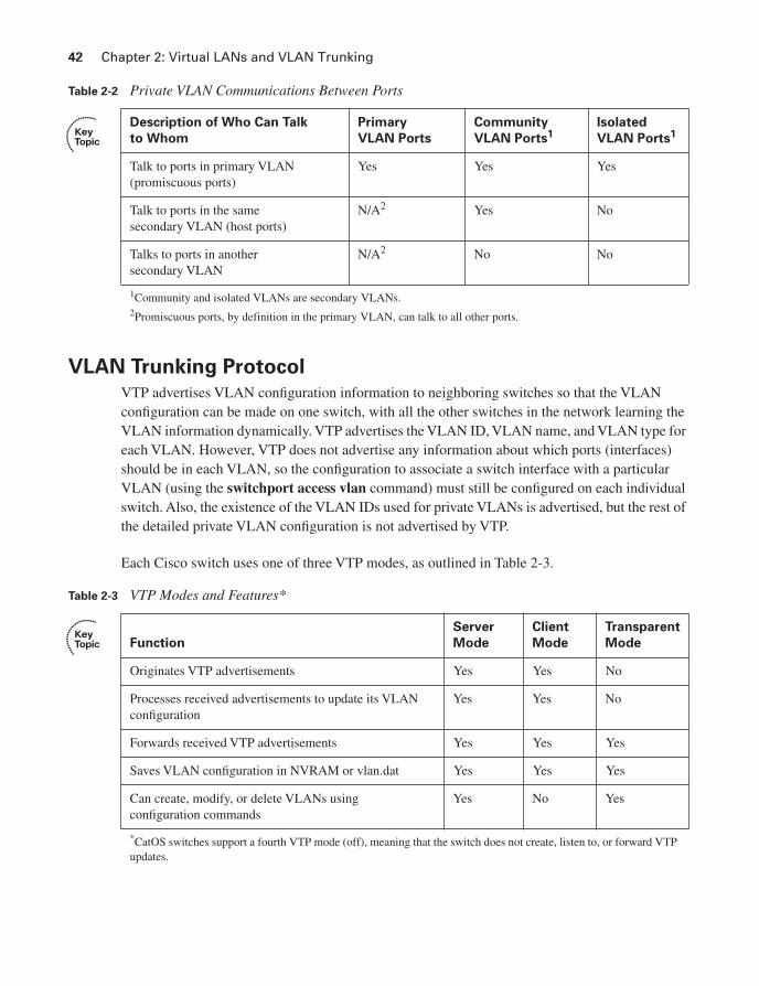
Secondary VLANs are either community VLANs or isolated VLANs. The engineer picks the type based on whether the device is part of a set of ports that should be allowed to send frames back and forth (community VLAN ports), or whether the device port should not be allowed to talk to any other ports besides those on the primary VLAN (isolated VLAN). Table 2-2 summarizes the behavior of private VLAN communications between ports.
42 Chapter 2: Virtual LANs and VLAN Trunking
VLAN Trunking Protocol
VTP advertises VLAN configuration information to neighboring switches so that the VLAN configuration can be made on one switch, with all the other switches in the network learning the VLAN information dynamically. VTP advertises the VLAN ID, VLAN name, and VLAN type for each VLAN. However, VTP does not advertise any information about which ports (interfaces) should be in each VLAN, so the configuration to associate a switch interface with a particular VLAN (using the switchport access vlan command) must still be configured on each individual switch. Also, the existence of the VLAN IDs used for private VLANs is advertised, but the rest of the detailed private VLAN configuration is not advertised by VTP.
Each Cisco switch uses one of three VTP modes, as outlined in Table 2-3.
Table 2-2 Private VLAN Communications Between Ports
Description of Who Can Talk
to Whom
Primary
VLAN Ports
Community
VLAN Ports1Isolated
VLAN Ports1
Talk to ports in primary VLAN (promiscuous ports)
Yes Yes Yes
Talk to ports in the same secondary VLAN (host ports)
N/A2 Yes No
Talks to ports in another secondary VLAN
N/A2 No No
1Community and isolated VLANs are secondary VLANs.2Promiscuous ports, by definition in the primary VLAN, can talk to all other ports.
Table 2-3 VTP Modes and Features*
Function
Server
Mode
Client
Mode
Transparent
Mode
Originates VTP advertisements Yes Yes No
Processes received advertisements to update its VLAN configuration
Yes Yes No
Forwards received VTP advertisements Yes Yes Yes
Saves VLAN configuration in NVRAM or vlan.dat Yes Yes Yes
Can create, modify, or delete VLANs using configuration commands
Yes No Yes
*CatOS switches support a fourth VTP mode (off), meaning that the switch does not create, listen to, or forward VTP updates.
VLAN Trunking Protocol 43
VTP Process and Revision NumbersThe VTP update process begins when a switch administrator, from a VTP server switch, adds, deletes, or updates the configuration for a VLAN. When the new configuration occurs, the VTP server increments the old VTP revision number by 1, and advertises the entire VLAN configuration database along with the new revision number.
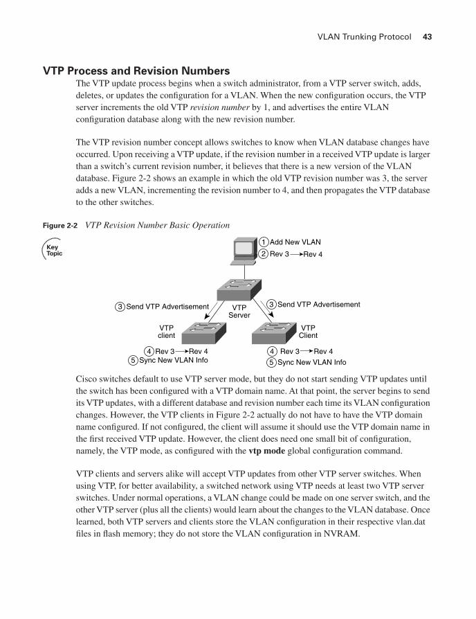
The VTP revision number concept allows switches to know when VLAN database changes have occurred. Upon receiving a VTP update, if the revision number in a received VTP update is larger than a switch’s current revision number, it believes that there is a new version of the VLAN database. Figure 2-2 shows an example in which the old VTP revision number was 3, the server adds a new VLAN, incrementing the revision number to 4, and then propagates the VTP database to the other switches.
Figure 2-2 VTP Revision Number Basic Operation
Cisco switches default to use VTP server mode, but they do not start sending VTP updates until the switch has been configured with a VTP domain name. At that point, the server begins to send its VTP updates, with a different database and revision number each time its VLAN configuration changes. However, the VTP clients in Figure 2-2 actually do not have to have the VTP domain name configured. If not configured, the client will assume it should use the VTP domain name in the first received VTP update. However, the client does need one small bit of configuration, namely, the VTP mode, as configured with the vtp mode global configuration command.
VTP clients and servers alike will accept VTP updates from other VTP server switches. When using VTP, for better availability, a switched network using VTP needs at least two VTP server switches. Under normal operations, a VLAN change could be made on one server switch, and the other VTP server (plus all the clients) would learn about the changes to the VLAN database. Once learned, both VTP servers and clients store the VLAN configuration in their respective vlan.dat files in flash memory; they do not store the VLAN configuration in NVRAM.
1 Add New VLAN
4 Rev 3 Rev 45 Sync New VLAN Info
VTPClient
VTPclient
VTPServer
3 Send VTP Advertisement
4 Rev 3 Rev 4
3 Send VTP Advertisement
5 Sync New VLAN Info
2 Rev 3 Rev 4
44 Chapter 2: Virtual LANs and VLAN Trunking
With multiple VTP servers installed in a LAN, it is possible to accidentally overwrite the VTP configuration in the network. If trunks fail and then changes are made on more than one VTP server, the VTP configuration databases could differ, with different configuration revision numbers. When the formerly-separated parts of the LAN reconnect using trunks, the VTP database with a higher revision number is propagated throughout the VTP domain, replacing some switches’ VTP databases. Note also that because VTP clients can actually originate VTP updates, under the right circumstances, a VTP client can update the VTP database on another VTP client or server. See http://www.ciscopress.com/1587201968 and look for downloads, to download a document that describes how a client could update the VLAN database on another VTP client or server. In summary, for a newly-connected VTP server or client to change another switch’s VTP database, the following must be true:
■ The new link connecting the new switch is trunking.
■ The new switch has the same VTP domain name as the other switches.
■ The new switch’s revision number is larger than that of the existing switches.
■ The new switch must have the same password, if configured on the existing switches.
The revision number and VTP domain name can be easily seen with a Sniffer trace; to prevent DoS attacks with VTP, set VTP passwords, which are encoded as message digests (MD5) in the VTP updates. Also, some installations simply use VTP transparent mode on all switches, which prevents switches from ever listening to other switch VTP updates and erroneously deleting their VLAN configuration databases.
VTP Configuration VTP sends updates out all active trunk interfaces (ISL or 802.1Q). However, with all default settings from Cisco, switches are in server mode, with no VTP domain name configured, and they do not send any VTP updates. Before any switches can learn VLAN information from another switch, at least one switch must have a bare-minimum VTP server configuration—specifically, a domain name.
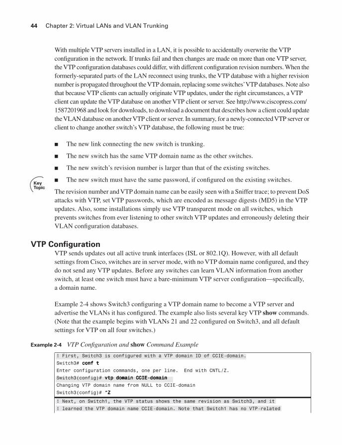
Example 2-4 shows Switch3 configuring a VTP domain name to become a VTP server and advertise the VLANs it has configured. The example also lists several key VTP show commands.(Note that the example begins with VLANs 21 and 22 configured on Switch3, and all default settings for VTP on all four switches.)
Example 2-4 VTP Configuration and show Command Example
! First, Switch3 is configured with a VTP domain ID of CCIE-domain.
Switch3# ccccoooonnnnffff tttt
Enter configuration commands, one per line. End with CNTL/Z.
Switch3(config)# vvvvttttpppp ddddoooommmmaaaaiiiinnnn CCCCCCCCIIIIEEEE----ddddoooommmmaaaaiiiinnnn
Changing VTP domain name from NULL to CCIE-domain
Switch3(config)# ^̂̂̂ZZZZ
! Next, on Switch1, the VTP status shows the same revision as Switch3, and it
! learned the VTP domain name CCIE-domain. Note that Switch1 has no VTP-related
VLAN Trunking Protocol 45
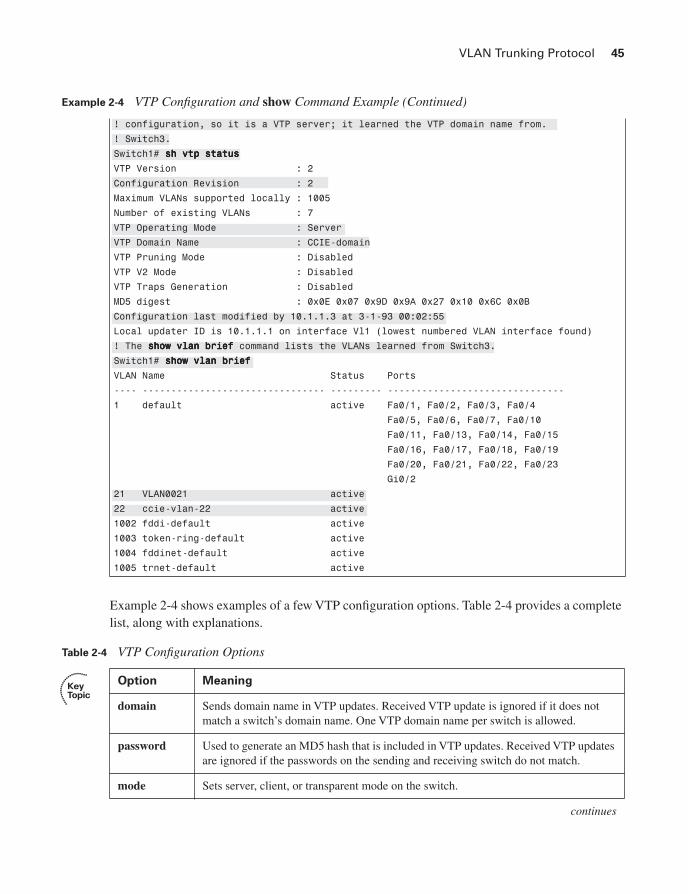
Example 2-4 shows examples of a few VTP configuration options. Table 2-4 provides a complete list, along with explanations.
! configuration, so it is a VTP server; it learned the VTP domain name from.
! Switch3.
Switch1# sssshhhh vvvvttttpppp ssssttttaaaattttuuuussss
VTP Version : 2
Configuration Revision : 2
Maximum VLANs supported locally : 1005
Number of existing VLANs : 7
VTP Operating Mode : Server
VTP Domain Name : CCIE-domain
VTP Pruning Mode : Disabled
VTP V2 Mode : Disabled
VTP Traps Generation : Disabled
MD5 digest : 0x0E 0x07 0x9D 0x9A 0x27 0x10 0x6C 0x0B
Configuration last modified by 10.1.1.3 at 3-1-93 00:02:55
Local updater ID is 10.1.1.1 on interface Vl1 (lowest numbered VLAN interface found)
! The sssshhhhoooowwww vvvvllllaaaannnn bbbbrrrriiiieeeeffff command lists the VLANs learned from Switch3.
Switch1# sssshhhhoooowwww vvvvllllaaaannnn bbbbrrrriiiieeeeffff
VLAN Name Status Ports
---- -------------------------------- --------- -------------------------------
1 default active Fa0/1, Fa0/2, Fa0/3, Fa0/4
Fa0/5, Fa0/6, Fa0/7, Fa0/10
Fa0/11, Fa0/13, Fa0/14, Fa0/15
Fa0/16, Fa0/17, Fa0/18, Fa0/19
Fa0/20, Fa0/21, Fa0/22, Fa0/23
Gi0/2
21 VLAN0021 active
22 ccie-vlan-22 active
1002 fddi-default active
1003 token-ring-default active
1004 fddinet-default active
1005 trnet-default active
Table 2-4 VTP Configuration Options
Option Meaning
domain Sends domain name in VTP updates. Received VTP update is ignored if it does not match a switch’s domain name. One VTP domain name per switch is allowed.
password Used to generate an MD5 hash that is included in VTP updates. Received VTP updates are ignored if the passwords on the sending and receiving switch do not match.
mode Sets server, client, or transparent mode on the switch.
continues
Example 2-4 VTP Configuration and show Command Example (Continued)
46 Chapter 2: Virtual LANs and VLAN Trunking
Normal-Range and Extended-Range VLANs
Some VLAN numbers are considered to be normal, whereas some others are considered to be extended.Normal-range VLANs are VLANs 1–1005, and can be advertised via VTP versions 1 and 2. These VLANs can be configured in VLAN database mode, with the details being stored in the vlan.dat file in Flash.
Extended-range VLANs range from 1006–4094, inclusive. However, these additional VLANs cannot be configured in VLAN database mode, nor stored in the vlan.dat file, nor advertised via VTP. In fact, to configure them, the switch must be in VTP transparent mode. (Also, you should take care to avoid using VLANs 1006–1024 for compatibility with CatOS-based switches.)
Both ISL and 802.1Q support extended-range VLANs today. Originally, ISL began life only supporting normal-range VLANs, using only 10 of the 15 bits reserved in the ISL header to identify the VLAN ID. The later-defined 802.1Q used a 12-bit VLAN ID field, thereby allowing support of the extended range. Following that, Cisco changed ISL to use 12 of its reserved 15 bits in the VLAN ID field, thereby supporting the extended range.
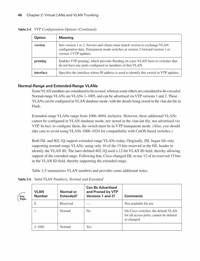
Table 2-5 summarizes VLAN numbers and provides some additional notes.
Option Meaning
version Sets version 1 or 2. Servers and clients must match version to exchange VLAN configuration data. Transparent mode switches at version 2 forward version 1 or version 2 VTP updates.
pruning Enables VTP pruning, which prevents flooding on a per-VLAN basis to switches that do not have any ports configured as members of that VLAN.
interface Specifies the interface whose IP address is used to identify this switch in VTP updates.
Table 2-5 Valid VLAN Numbers, Normal and Extended
VLAN
Number
Normal or
Extended?
Can Be Advertised
and Pruned by VTP
Versions 1 and 2? Comments
0 Reserved — Not available for use
1 Normal No On Cisco switches, the default VLAN for all access ports; cannot be deleted or changed
2–1001 Normal Yes
Table 2-4 VTP Configuration Options (Continued)

VLAN Trunking Protocol 47
Storing VLAN Configuration
Catalyst IOS stores VLAN and VTP configuration in one of two places—either in a Flash file called vlan.dat or in the running configuration. (Remember that the term “Catalyst IOS” refers to a switch that uses IOS, not the Catalyst OS, which is often called CatOS.) IOS chooses the storage location in part based on the VTP mode, and in part based on whether the VLANs are normal-range VLANs or extended-range VLANs. Table 2-6 describes what happens based on what configuration mode is used to configure the VLANs, the VTP mode, and the VLAN range. (Note that VTP clients also store the VLAN configuration in vlan.dat, and they do not understand extended range VLANs.)
Of particular interest for those of you stronger with CatOS configuration skills is that when you erase the startup-config file, and reload the Cisco IOS switch, you do not actually erase the
VLAN
Number
Normal or
Extended?
Can Be Advertised
and Pruned by VTP
Versions 1 and 2? Comments
1002–1005 Normal No Defined specifically for use with FDDI and TR translational bridging
1006–4094 Extended No
Table 2-6 VLAN Configuration and Storage
Function When in VTP Server Mode
When in VTP
Transparent Mode
Normal-range VLANs can be configured from
Both VLAN database and configuration modes
Both VLAN database and configuration modes
Extended-range VLANs can be configured from
Nowhere—cannot be configured Configuration mode only
VTP and normal-range VLAN configuration commands are stored in
vlan.dat in Flash Both vlan.dat in Flash and running configuration1
Extended-range VLAN configuration commands stored in
Nowhere—extended range not allowed in VTP server mode
Running configuration only
1When a switch reloads, if the VTP mode or domain name in the vlan.dat file and the startup-config file differ, the switch uses only the vlan.dat file’s contents for VLAN configuration.
NOTE The configuration characteristics referenced in Table 2-6 do not include the interface configuration command switchport access vlan; it includes the commands that create a VLAN (vlan command) and VTP configuration commands.
Table 2-5 Valid VLAN Numbers, Normal and Extended (Continued)

48 Chapter 2: Virtual LANs and VLAN Trunking
normal-range VLAN and VTP configuration information. To erase the VLAN and VTP configuration, you must use the delete flash:vlan.dat exec command. Also note that if multiple switches are in VTP server mode, if you delete vlan.dat on one switch and then reload it, as soon as the switch comes back up and brings up a trunk, it learns the old VLAN database via a VTP update from the other VTP server.
VLAN Trunking: ISL and 802.1Q
VLAN trunking allows switches, routers, and even PCs with the appropriate NICs to send traffic for multiple VLANs across a single link. In order to know to which VLAN a frame belongs, the sending switch, router, or PC adds a header to the original Ethernet frame, with that header having a field in which to place the VLAN ID of the associated VLAN. This section describes the protocol details for the two trunking protocols, followed by the details of how to configure trunking.
ISL and 802.1Q ConceptsIf two devices are to perform trunking, they must agree to use either ISL or 802.1Q, because there are several differences between the two, as summarized in Table 2-7.
ISL and 802.1Q differ in how they add a header to the Ethernet frame before sending it over a trunk. ISL adds a new 26-byte header, plus a new trailer (to allow for the new FCS value), encapsulating the original frame. This encapsulating header uses the source address (listed as SA in Figure 2-3) of the device doing the trunking, instead of the source MAC of the original frame. ISL uses a multicast destination address (listed as DA in Figure 2-3) of either 0100.0C00.0000 or 0300.0C00.0000.
802.1Q inserts a 4-byte header, called a tag, into the original frame (right after the Source Address field). The original frame’s addresses are left intact. Normally, an Ethernet controller would expect to find either an Ethernet Type field or 802.3 Length field right after the Source Address field. With an 802.1Q tag, the first 2 bytes after the Address fields holds a registered Ethernet type value of 0x8100, which implies that the frame includes an 802.1Q header. Because 802.1Q does not actually encapsulate the original frame, it is often called frame tagging. Figure 2-3 shows the contents of the headers used by both ISL and 802.1Q.
Table 2-7 Comparing ISL and 802.1Q
Feature ISL 802.1Q
VLANs supported Normal and extended range1 Normal and extended range
Protocol defined by Cisco IEEE
Encapsulates original frame or inserts tag Encapsulates Inserts tag
Supports native VLAN No Yes
1ISL originally supported only normal-range VLANs, but was later improved to support extended-range VLANs as well.

VLAN Trunking: ISL and 802.1Q 49
Figure 2-3 ISL and 802.1Q Frame Marking Methods
Finally, the last row from Table 2-7 refers to the native VLAN. 802.1Q does not tag frames sent inside the native VLAN. The native VLAN feature allows a switch to attempt to use 802.1Q trunking on an interface, but if the other device does not support trunking, the traffic for that one native VLAN can still be sent over the link. By default, the native VLAN is VLAN 1.
ISL and 802.1Q ConfigurationCisco switches use the Dynamic Trunk Protocol (DTP) to dynamically learn whether the device on the other end of the cable wants to perform trunking and, if so, which trunking protocol to use. DTP learns whether to trunk based on the DTP mode defined for an interface. Cisco switches default to use the DTP desirable mode, which means that the switch initiates sending DTP messages, hoping that the device on the other end of the segment replies with another DTP message. If a reply is received, DTP can detect whether both switches can trunk and, if so, which type of trunking to use. If both switches support both types of trunking, they choose to use ISL. (An upcoming section, “Trunk Configuration Compatibility,” covers the different DTP modes and how they work.)
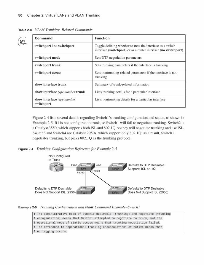
With the DTP mode set to desirable, switches can simply be connected, and they should dynamically form a trunk. You can, however, configure trunking details and verify the results with show commands. Table 2-8 lists some of the key Catalyst IOS commands related to trunking.
ISL Header26 bytes
CRC4 bytes
Encapsulated Ethernet Frame
VLAN
DA Type User SA LEN AAAA03 HSA VLAN BPDU INDEX RES
BPDU
Dest Src Len/Etype Data FCS
Dest Src Etype Tag Len/Etype Data FCS
Priority VLAN-ID
OriginalFrame
TaggedFrame
50 Chapter 2: Virtual LANs and VLAN Trunking
Figure 2-4 lists several details regarding Switch1’s trunking configuration and status, as shown in Example 2-5. R1 is not configured to trunk, so Switch1 will fail to negotiate trunking. Switch2 is a Catalyst 3550, which supports both ISL and 802.1Q, so they will negotiate trunking and use ISL. Switch3 and Switch4 are Catalyst 2950s, which support only 802.1Q; as a result, Switch1 negotiates trunking, but picks 802.1Q as the trunking protocol.
Figure 2-4 Trunking Configuration Reference for Example 2-5
Table 2-8 VLAN Trunking–Related Commands
Command Function
switchport | no switchport Toggle defining whether to treat the interface as a switch interface (switchport) or as a router interface (no switchport)
switchport mode Sets DTP negotiation parameters
switchport trunk Sets trunking parameters if the interface is trunking
switchport access Sets nontrunking-related parameters if the interface is not trunking
show interface trunk Summary of trunk-related information
show interface type number trunk Lists trunking details for a particular interface
show interface type numberswitchport
Lists nontrunking details for a particular interface
Example 2-5 Trunking Configuration and show Command Example–Switch1
! The administrative mode of dynamic desirable (trunking) and negotiate (trunking
! encapsulation) means that Switch1 attempted to negotiate to trunk, but the
! operational mode of static access means that trunking negotiation failed.
! The reference to “operational trunking encapsulation” of native means that
! no tagging occurs.
SW1Gi0/1
R1
Not Configuredto Trunk
Defaults to DTP DesirableSupports ISL or .1Q
Defaults to DTP DesirableDoes Not Support ISL (2950)
Defaults to DTP DesirableDoes Not Support ISL (2950)
Fa0/12Fa0/24
Fa0/1
SW2
SW4SW3

VLAN Trunking: ISL and 802.1Q 51
Switch1# sssshhhhoooowwww iiiinnnntttt ffffaaaa 0000////1111 sssswwwwiiiittttcccchhhhppppoooorrrrtttt
Name: Fa0/1
Switchport: Enabled
Administrative Mode: dynamic desirable
Operational Mode: static access
Administrative Trunking Encapsulation: negotiate
Operational Trunking Encapsulation: native
Negotiation of Trunking: On
Access Mode VLAN: 1 (default)
Trunking Native Mode VLAN: 1 (default)
Administrative private-vlan host-association: none
Administrative private-vlan mapping: none
Operational private-vlan: none
Trunking VLANs Enabled: ALL
Pruning VLANs Enabled: 2-1001
Protected: false
Unknown unicast blocked: disabled
Unknown multicast blocked: disabled
Voice VLAN: none (Inactive)
Appliance trust: none
! Next, the sssshhhhoooowwww iiiinnnntttt ggggiiiigggg 0000////1111 ttttrrrruuuunnnnkkkk command shows the configured mode
! (desirable), and the current status (N-ISL), meaning negotiated ISL. Note
! that the trunk supports the extended VLAN range as well.
Switch1# sssshhhhoooowwww iiiinnnntttt ggggiiiigggg 0000////1111 ttttrrrruuuunnnnkkkk
Port Mode Encapsulation Status Native vlan
Gi0/1 desirable n-isl trunking 1
Port Vlans allowed on trunk
Gi0/1 1-4094
Port Vlans allowed and active in management domain
Gi0/1 1,21-22
Port Vlans in spanning tree forwarding state and not pruned
Gi0/1 1,21-22
! Next, Switch1 lists all three trunks – the segments connecting to the other
! three switches – along with the type of encapsulation.
Switch1# sssshhhhoooowwww iiiinnnntttt ttttrrrruuuunnnnkkkk
Port Mode Encapsulation Status Native vlan
Fa0/12 desirable n-802.1q trunking 1
Fa0/24 desirable n-802.1q trunking 1
Gi0/1 desirable n-isl trunking 1
Port Vlans allowed on trunk
Fa0/12 1-4094
continues
Example 2-5 Trunking Configuration and show Command Example–Switch1 (Continued)

52 Chapter 2: Virtual LANs and VLAN Trunking
Allowed, Active, and Pruned VLANs
Although a trunk can support VLANs 1–4094, several mechanisms reduce the actual number of VLANs whose traffic flows over the trunk. First, VLANs can be administratively forbidden from existing over the trunk using the switchport trunk allowed interface subcommand. Also, any allowed VLANs must be configured on the switch before they are considered active on the trunk. Finally, VTP can prune VLANs from the trunk, with the switch simply ceasing to forward frames from that VLAN over the trunk.
The show interface trunk command lists the VLANs that fall into each category, as shown in the last command in Example 2-5. The categories are summarized as follows:
■ Allowed VLANs—Each trunk allows all VLANs by default. However, VLANs can be removed or added to the list of allowed VLANs by using the switchport trunk allowedcommand.
■ Allowed and active—To be active, a VLAN must be in the allowed list for the trunk (based on trunk configuration), and the VLAN must exist in the VLAN configuration on the switch. With PVST+, an STP instance is actively running on this trunk for the VLANs in this list.
■ Active and not pruned—This list is a subset of the “allowed and active” list, with any VTP-pruned VLANs removed.
Trunk Configuration Compatibility
In most production networks, switch trunks are configured using the same standard throughout the network. For instance, rather than allow DTP to negotiate trunking,, many engineers configure trunk interfaces to always trunk (switchport mode trunk) and disable DTP on ports that should not trunk. IOS includes several commands that impact whether a particular segment becomes a trunk. Because many enterprises use a typical standard, it is easy to forget the nuances of how the related commands work. This section covers those small details.
Fa0/24 1-4094
Gi0/1 1-4094
Port Vlans allowed and active in management domain
Fa0/12 1,21-22
Fa0/24 1,21-22
Gi0/1 1,21-22
Port Vlans in spanning tree forwarding state and not pruned
Fa0/12 1,21-22
Fa0/24 1,21-22
Gi0/1 1,21-22
Example 2-5 Trunking Configuration and show Command Example–Switch1 (Continued)
VLAN Trunking: ISL and 802.1Q 53
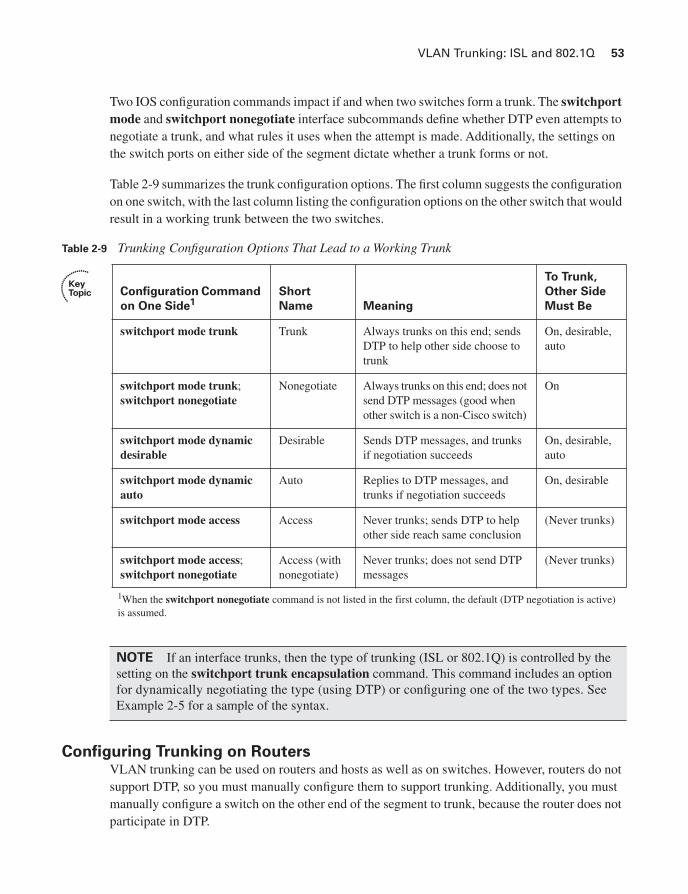
Two IOS configuration commands impact if and when two switches form a trunk. The switchportmode and switchport nonegotiate interface subcommands define whether DTP even attempts to negotiate a trunk, and what rules it uses when the attempt is made. Additionally, the settings on the switch ports on either side of the segment dictate whether a trunk forms or not.
Table 2-9 summarizes the trunk configuration options. The first column suggests the configuration on one switch, with the last column listing the configuration options on the other switch that would result in a working trunk between the two switches.
Configuring Trunking on RoutersVLAN trunking can be used on routers and hosts as well as on switches. However, routers do not support DTP, so you must manually configure them to support trunking. Additionally, you must manually configure a switch on the other end of the segment to trunk, because the router does not participate in DTP.
Table 2-9 Trunking Configuration Options That Lead to a Working Trunk
Configuration Command
on One Side1Short
Name Meaning
To Trunk,
Other Side
Must Be
switchport mode trunk Trunk Always trunks on this end; sends DTP to help other side choose to trunk
On, desirable, auto
switchport mode trunk;switchport nonegotiate
Nonegotiate Always trunks on this end; does not send DTP messages (good when other switch is a non-Cisco switch)
On
switchport mode dynamic desirable
Desirable Sends DTP messages, and trunks if negotiation succeeds
On, desirable, auto
switchport mode dynamic auto
Auto Replies to DTP messages, and trunks if negotiation succeeds
On, desirable
switchport mode access Access Never trunks; sends DTP to help other side reach same conclusion
(Never trunks)
switchport mode access;switchport nonegotiate
Access (with nonegotiate)
Never trunks; does not send DTP messages
(Never trunks)
1When the switchport nonegotiate command is not listed in the first column, the default (DTP negotiation is active) is assumed.
NOTE If an interface trunks, then the type of trunking (ISL or 802.1Q) is controlled by the setting on the switchport trunk encapsulation command. This command includes an option for dynamically negotiating the type (using DTP) or configuring one of the two types. See Example 2-5 for a sample of the syntax.

54 Chapter 2: Virtual LANs and VLAN Trunking
The majority of router trunking configurations use subinterfaces, with each subinterface being associated with one VLAN. The subinterface number does not have to match the VLAN ID; rather, the encapsulation command sits under each subinterface, with the associated VLAN ID being part of the encapsulation command. Also, because good design calls for one IP subnet per VLAN, if the router wants to forward IP packets between the VLANs, the router needs to have an IP address associated with each trunking subinterface.
You can configure 802.1Q native VLANs under a subinterface or under the physical interface on a router. If configured under a subinterface, you use the encapsulation dot1q vlan-id nativesubcommand, with the inclusion of the native keyword meaning that frames exiting this subinterface should not be tagged. As with other router trunking configurations, the associated IP address would be configured on that same subinterface. Alternately, if not configured on a subinterface, the router assumes that the native VLAN is associated with the physical interface. In this case, the encapsulation command is not needed under the physical interface; the associated IP address, however, would need to be configured under the physical interface.
Example 2-6 shows an example configuration for Router1 in Figure 2-1, both for ISL and 802.1Q. In this case, Router1 needs to forward packets between the subnets on VLANs 21 and 22. The first part of the example shows ISL configuration, with no native VLANs, and therefore only a subinterface being used for each VLAN. The second part of the example shows an alternative 802.1Q configuration, using the option of placing the native VLAN (VLAN 21) configuration on the physical interface.
Example 2-6 Trunking Configuration on Router1
! Note the subinterface on the fa 0/0 interface, with the eeeennnnccccaaaappppssssuuuullllaaaattttiiiioooonnnn
! command noting the type of trunking, as well as the VLAN number. The
! subinterface does not have to be the VLAN ID. Also note the IP addresses for
! each interface, allowing Router1 to route between VLANs.
interface fastethernet 0/0.1
ip address 10.1.21.1 255.255.255.0
encapsulation isl 21
!
interface fastethernet 0/0.2
ip address 10.1.22.1 255.255.255.0
encapsulation isl 22
! Next, an alternative 802.1Q configuration is shown. Note that this 802.1Q configuration
! places the IP address
! for VLAN 21 on the physical interface; the router simply associates the
! physical interface with the native VLAN. Alternatively, a subinterface could be
! used, with the eeeennnnccccaaaappppssssuuuullllaaaattttiiiioooonnnn ddddooootttt1111qqqq 22221111 nnnnaaaattttiiiivvvveeee command specifying that the router
! should treat this VLAN as the native VLAN.
interface fastethernet 0/0
ip address 10.1.21.1 255.255.255.0
!
interface fastethernet 0/0.2
ip address 10.1.22.1 255.255.255.0
encapsulation dot1q 22

VLAN Trunking: ISL and 802.1Q 55
Note also that the router does not have an explicitly defined allowed VLAN list. However, the allowed VLAN list is implied based on the configured VLANs. For instance, in this example, Router1 allows VLAN 1 (because it cannot be deleted), VLAN 21, and VLAN 22. A show interface trunk command on Switch1 would show only 1, 21, and 22 as the allowed VLANs on FA0/1.
802.1Q-in-Q TunnelingTraditionally, VLANs have not extended beyond the WAN boundary. VLANs in one campus extend to a WAN edge router, but VLAN protocols are not used on the WAN.
Today, several emerging alternatives exist for the passage of VLAN traffic across a WAN, including 802.1Q-in-Q, Ethernet over MPLS (EoMPLS), and VLAN MPLS (VMPLS). While these topics are more applicable to the CCIE Service Provider certification, you should at least know the concept of 802.1 Q-in-Q tunneling.
Also known as Q-in-Q or Layer 2 protocol tunneling, 802.1Q-in-Q allows an SP to preserve 802.1Q VLAN tags across a WAN service. By doing so, VLANs actually span multiple geographically dispersed sites. Figure 2-5 shows the basic idea.
Figure 2-5 Q-in-Q: Basic Operation
C1-SW1
C2-SW1
SP:Customer1: VLAN 5Customer2: VLAN 6
VLANs 100-199
VLANs 100-500
C1-SW2
C2-SW2
SP-SW2
VLANID 100
DataVLANID 6
Eth.Header
VLANID 100
DataVLANID 5
Eth.Header
SP-SW1
VLANID 100
DataEth.
HeaderVLANID 100
DataEth.
Header
VLANID 100
DataEth.
HeaderVLANID 100
DataEth.
Header

56 Chapter 2: Virtual LANs and VLAN Trunking
The ingress SP switch takes the 802.1Q frame, and then tags each frame entering the interface with an additional 802.1Q header. In this case, all of Customer1’s frames are tagged as VLAN 5 as they pass over the WAN; Customer2’s frames are tagged with VLAN 6. After removing the tag at egress, the customer switch sees the original 802.1Q frame, and can interpret the VLAN ID correctly. The receiving SP switch (SP-SW2 in this case) can keep the various customers’ traffic separate based on the additional VLAN tags.
Using Q-in-Q, an SP can offer VLAN services, even when the customers use overlapping VLAN IDs. Customers get more flexibility for network design options, particularly with metro Ethernet services. Plus, CDP and VTP traffic passes transparently over the Q-in-Q service.
Configuring PPPoE
Although it might seem out of place in this chapter on VLANs and VLAN trunking, Point-to-Point Protocol over Ethernet (PPPoE) fits best here because it’s an Ethernet encapsulation protocol. PPPoE is widely used for digital subscriber line (DSL) Internet access because the public telephone network uses ATM for its transport protocol; therefore, Ethernet frames must be encapsulated in a protocol supported over both Ethernet and ATM. PPP is the natural choice. The PPP Client feature permits a Cisco IOS router, rather than an endpoint host, to serve as the client in a network. This permits multiple hosts to connect over a single PPPoE connection.
In a DSL environment, PPP interface IP addresses are derived from an upstream DHCP server using IP Configuration Protocol (IPCP). Therefore, IP address negotiation must be enabled on the router’s dialer interface. This is done using the ip address negotiated command in the dialer interface configuration.
Because of the 8-byte PPP header, the MTU for PPPoE is usually set to 1492 bytes so that the entire encapsulated frame fits within the 1500-byte Ethernet frame. A maximum transmission unit (MTU) mismatch prevents a PPPoE connection from coming up. Checking the MTU setting is a good first step when troubleshooting PPPoE connections.
Those familiar with ISDN BRI configuration will recognize the dialer interface configuration and related commands in Example 2-7. The key difference between ISDN BRI configuration and PPPoE is the pppoe-client dial-pool-number command.
Configuring an Ethernet edge router for PPPoE Client mode is the focus of this section. This task requires configuring the Ethernet interface (physical or subinterface) and a corresponding dialer interface. The information in this section applies to Cisco IOS Release 12.2(13)T and later, and 12.3 and 12.4 releases.

Configuring PPPoE 57
Figure 2-6 shows the topology. Example 2-7 shows the configuration steps. The first step is to configure the outside Ethernet interface as a PPPoE client and assign it a dialer interface number. The second step is to configure the corresponding dialer interface. Additional steps, including Network Address Translation (NAT) configuration, are also shown.
Figure 2-6 PPPoE Topology for Example 2-7
Example 2-7 Configuring PPPoE on EdgeRouter
EdgeRouter# ccccoooonnnnffff tttt
EdgeRouter(config)# iiiinnnntttteeeerrrrffffaaaacccceeee ffffaaaa0000////1111
EdgeRouter(config-if)# iiiipppp aaaaddddddddrrrreeeessssssss 111199992222....111166668888....111100000000....1111 222255555555....222255555555....222255555555....0000
EdgeRouter(config-if)# iiiipppp nnnnaaaatttt iiiinnnnssssiiiiddddeeee
EdgeRouter(config)# iiiinnnntttteeeerrrrffffaaaacccceeee ffffaaaa0000////1111
EdgeRouter(config-if)# ppppppppppppooooeeee----cccclllliiiieeeennnntttt ddddiiiiaaaallll----ppppoooooooollll----nnnnuuuummmmbbbbeeeerrrr 1111
EdgeRouter(config-if)# eeeexxxxiiiitttt
EdgeRouter(config)# iiiinnnntttteeeerrrrffffaaaacccceeee ddddiiiiaaaalllleeeerrrr1111
EdgeRouter(config-if)# mmmmttttuuuu 1111444499992222
EdgeRouter(config-if)# eeeennnnccccaaaappppssssuuuullllaaaattttiiiioooonnnn pppppppppppp
EdgeRouter(config-if)# iiiipppp aaaaddddddddrrrreeeessssssss nnnneeeeggggoooottttiiiiaaaatttteeeedddd
EdgeRouter(config-if)# pppppppppppp aaaauuuutttthhhheeeennnnttttiiiiccccaaaattttiiiioooonnnn cccchhhhaaaapppp
!The remaining CHAP commands have been omitted for brevity.
EdgeRouter(config-if)# iiiipppp nnnnaaaatttt oooouuuuttttssssiiiiddddeeee
EdgeRouter(config-if)# ddddiiiiaaaalllleeeerrrr ppppoooooooollll 1111
continues
Workstations
EdgeRouter
DSLAccessMultiplexer
LAN
Fa0/0
ATMNetwork
DSLCPE
AccessConcentrator
Fa0/1

58 Chapter 2: Virtual LANs and VLAN Trunking
You can verify PPPoE connectivity using the command show pppoe session. Cisco IOS includes debug functionality for PPPoE through the debug pppoe [data | errors | events | packets]command.
EdgeRouter(config-if)# ddddiiiiaaaalllleeeerrrr----ggggrrrroooouuuupppp 1111
EdgeRouter(config-if)# eeeexxxxiiiitttt
EdgeRouter(config)# ddddiiiiaaaalllleeeerrrr----lllliiiisssstttt 1111 pppprrrroooottttooooccccoooollll iiiipppp ppppeeeerrrrmmmmiiiitttt
EdgeRouter(config)# iiiipppp nnnnaaaatttt iiiinnnnssssiiiiddddeeee ssssoooouuuurrrrcccceeee lllliiiisssstttt 1111 iiiinnnntttteeeerrrrffffaaaacccceeee ddddiiiiaaaalllliiiieeeerrrr1111 oooovvvveeeerrrrllllooooaaaadddd
EdgeRouter(config)# aaaacccccccceeeessssssss----lllliiiisssstttt 1111 ppppeeeerrrrmmmmiiiitttt 111199992222....111166668888....111100000000....0000 0000....0000....0000....222255555555
EdgeRouter(config)# iiiipppp rrrroooouuuutttteeee 0000....0000....0000....0000 0000....0000....0000....0000 ddddiiiiaaaalllleeeerrrr1111
Example 2-7 Configuring PPPoE on EdgeRouter (Continued)

Foundation Summary 59
Foundation Summary
This section lists additional details and facts to round out the coverage of the topics in this chapter. Unlike most of the Cisco Press Exam Certification Guides, this “Foundation Summary” does not repeat information presented in the “Foundation Topics” section of the chapter. Please take the time to read and study the details in the “Foundation Topics” section of the chapter, as well as review items noted with a Key Topic icon.
Table 2-10 lists some of the most popular IOS commands related to the topics in this chapter. (The command syntax was copied from the Catalyst 3550 Multilayer Switch Command Reference, 12.1(20)EA2. Note that some switch platforms may have differences in the command syntax.)
Table 2-10 Catalyst IOS Commands Related to Chapter 2
Command Description
show mac address-table [aging-time | count | dynamic | static] [address hw-addr][interface interface-id] [vlan vlan-id]
Displays the MAC address table; the security option displays information about the restricted or static settings
show interfaces [interface-id | vlan vlan-id]switchport | trunk]
Displays detailed information about an interface operating as an access port or a trunk
show vlan [brief | id vlan-id |name vlan-name | summary]
EXEC command that lists information about VLAN
show vlan [vlan] Displays VLAN information
show vtp status Lists VTP configuration and status information
switchport mode {access | dot1q-tunnel | dynamic {auto | desirable} | trunk}
Configuration command setting nontrunking (access), trunking, and dynamic trunking (autoand desirable) parameters
switchport nonegotiate Interface subcommand that disables DTP messages; interface must be configured as trunk or access port
switchport trunk {allowed vlan vlan-list} | {encapsulation {dot1q | isl | negotiate}} | {native vlan vlan-id} | {pruning vlan vlan-list}
Interface subcommand used to set parameters used when the port is trunking
switchport access vlan vlan-id Interface subcommand that statically configures the interface as a member of that one VLAN
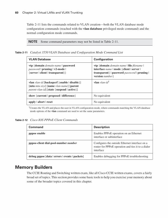
60 Chapter 2: Virtual LANs and VLAN Trunking
Table 2-11 lists the commands related to VLAN creation—both the VLAN database mode configuration commands (reached with the vlan database privileged mode command) and the normal configuration mode commands.
Table 2-12 Cisco IOS PPPoE Client Commands
Memory Builders
The CCIE Routing and Switching written exam, like all Cisco CCIE written exams, covers a fairly broad set of topics. This section provides some basic tools to help you exercise your memory about some of the broader topics covered in this chapter.
NOTE Some command parameters may not be listed in Table 2-11.
Table 2-11 Catalyst 3550 VLAN Database and Configuration Mode Command List
VLAN Database Configuration
vtp {domain domain-name | passwordpassword | pruning | v2-mode | {server | client | transparent}}
vtp {domain domain-name | file filename | interface name | mode {client | server | transparent} | password password | pruning | version number}
vlan vlan-id [backupcrf {enable | disable}][mtu mtu-size] [name vlan-name] [parentparent-vlan-id] [state {suspend | active}]
vlan vlan-id1
show {current | proposed | difference} No equivalent
apply | abort | reset No equivalent
1Creates the VLAN and places the user in VLAN configuration mode, where commands matching the VLAN database mode options of the vlan command are used to set the same parameters.
Command Description
pppoe enable Enables PPPoE operation on an Ethernet interface or subinterface
pppoe-client dial-pool-number number Configures the outside Ethernet interface on a router for PPPoE operation and ties it to a dialer interface
debug pppoe [data | errors | events | packets] Enables debugging for PPPoE troubleshooting

Memory Builders 61
Fill In Key Tables from Memory Appendix G, “Key Tables for CCIE Study,” on the CD in the back of this book contains empty sets of some of the key summary tables in each chapter. Print Appendix G, refer to this chapter’s tables in it, and fill in the tables from memory. Refer to Appendix H, “Solutions for Key Tables for CCIE Study,” on the CD to check your answers.
DefinitionsNext, take a few moments to write down the definitions for the following terms:
VLAN, broadcast domain, DTP, VTP pruning, 802.1Q, ISL, native VLAN, encapsulation, private VLAN, promiscuous port, community VLAN, isolated VLAN, 802.1Q-in-Q, Layer 2 protocol tunneling, PPPoE, DSL.
Refer to the glossary to check your answers.
Further ReadingThe topics in this chapter tend to be covered in slightly more detail in CCNP Switching exam preparation books. For more details on these topics, refer to the Cisco Press CCNP preparation books found at www.ciscopress.com/ccnp.
Cisco LAN Switching, by Kennedy Clark and Kevin Hamilton, is an excellent reference for LAN-related topics in general, and certainly very useful for CCIE written and lab exam preparation.

Index
Numerics10BASE2, 2610BASE5, 2610BASE-T, 26802.1Q trunking, 48–49
configuring, 49–51PVST+, 75VLAN trunking, 48–49
configuration, 49–50802.1Q-in-Q tunneling, 55–56802.1X, 777–780
configuration, 779EAP, 777, 779–780
802.2 LLC Type fields, 17
AAAA (authentication, authorization,
and accounting)authentication methods, 50–51, 761–763CLI, 50, 760–761groups of AAA servers, 764overriding defaults for login security,
764–765aaa authentication command, 763–764aaa authentication ppp default, 765abbreviating IPv6 addresses, 885ABRs (Area Border Routers), 270
stubby areas, 281access lists, statements, 52, 53, 786access ports, protecting, 89ACEs (Access Control Entries), 785
IP ACL, 52–53, 785–787ACLs
rate-limit ACL, 600IPv6, 903
ACS (Cisco Secure Access Control Server), 760
active and not pruned VLANs, 52active routes (EIGRP), 231–233
stuck-in-active state, 233–234Active timer (EIGRP), 234AD (administrative distance), 320–321
preventing suboptimal routes, 332–337adaptive shaping, 627
configuring, 584enabling, 590Frame Relay, 627FRTS, 590
addingdefault routes to BGP, 391–392eBGP routes to IP routing tables, 402–403iBGP routes to IP routing tables, 404–419multiple BGP routes to IP routing
tables, 460address family, 846address formats, Ethernet, 16–17Address Resolution Protocol. See ARPaddresses
Ethernet, 15–16inappropriate IP addresses, 790MAC addresses
mapping to multicast IP addresses, 656–657
overriding, 17tables, displaying, 59–60, 102,
213, 811multicast IP addresses, 652
adjacencies, 221–224adjacency tables, 822
ARP and inverse ARP, 188–189administrative scoping, 700administrative weight, 466–467advertising BGP routes to neighbors, 393
BGP Update message, 393–394
determining contents of updates, 28–29, 394–396
impact of decision process and NEXT_HOP, 396–401
AF (Assured Forwarding) PHB, 499AF DSCPs, 499–500aggregatable global addresses, 886–887aggregate-address command, 388–389,
433, 472BGP route summarization, 439–440
aggregate-address suppress-map command, 439
alignment errors, 93allocation of subnets, 119–120allow-default keyword, 789allowed VLANs, 52anycast IPv6 addresses, 891Anycast RP with MSDP, 737–740area authentication (OSPF), 22,
299–300Area Border Routers (ABRs), 270area filter-list, 295area range command, 296area stub command, 282area virtual-link command, 300ARP (Address Resolution Protocol) , 146–147,
188–189DAI, 771gratuitous ARPs, 772
AS_PATH attribute, 458filtering BGP updates, 440–441
AS_PATH filters, 446–449AS_SET and AS_CONFED_SEQ, 449,
452, 455BGP AS_PATH and AS_PATH segment
types, 441–443matching AS_PATHs, 446–449regular expressions, 443–444
manual summaries, BGP tables, 28segment types, 441–443shortest AS_PATH, 469–470
prepending and route aggregation, 471–473
removing private ASNs, 470AS_SET attribute, 449, 452, 455ASBRs (Autonomous System Boundary
Routers), 270ASNs (autonomous system numbers), 370,
442, 469–471, 654removing private ASNs
AS (autonomous systems)multiple adjacent AS, 476single adjacent AS, 475
Assert messages. PIM, 713–714as-set option, 389assigning
interfaces to VLANs, 39IP addresses, DHCP, 148–150IPv6 unicast addresses to router interface,
888–889authentication, 50, 51, 761–763
802.1X, EAP, 777, 779–780configuring OSPF, 298–301EIGRP, 238–239OSPFv3 unicast routing protocols, 918RIP, 17
auto-cost reference-bandwidth, 292automatic 6to4 tunnels, 937–938automatic medium-dependent interface
(Auto-MDIX), 8automatic summarization, EIGRP, 239Auto-MDIX (automatic medium-dependent
interface crossover), 8autonegotiation, 8–10Autonomous System Boundary Routers
(ASBRs), 270

988
AutoQoSfor Enterprise, 522–523for VoIP, 520
on routers, 521–522on switches, 520–521
Auto-RP, 731–733autosummarization, RIP, 15–17
impact on redistributed routes and network command, 385–387
auto-summary command, 388aux, 764
BBackboneFast, optimizing STP, 79, 81backdoor routes, IP routing tables, 403–404bandwidth
CBWFQ, limiting, 538–541LLQ, 543–544
bandwidth command, 535, 538, 583bandwidth percent command, 539bandwidth remaining percent command, 539Bc (committed burst), 573, 41
CB Policing defaults, 597default value, calculating, 597
Be (excess burst), 573–574, 582CB Policing defaults, 597default value, calculating, 597traffic shaping, 574
BECN (Backward Explicit Congestion Notification) , 576, 627
BGP (Border Gateway Protocol), 270advertising routes to neighbors, 393
BGP Update message, 393–394determining contest of updates,
394–396impact of decision process and
NEXT_HOP, 396–401AS_PATH, 370command references, 421, 489confederations, 409–411
configuring, 411–414decision process, 456–458
adding multiple BGP routes to IP routing tables, 460
BGP PAs, 463–464, 466mnemonics for memorizing, 460–462tiebreakers, 458–460, 477
filtering tools, 427, 433–434
filtering updates based on NLRI, 434–437route maps, 437soft reconfiguration, 438
maximum-paths command, 481–482message types, 378–379neighbor relationships, building, 371
eBGP, 375–376iBGP, 372–375
ORIGIN path attribute, 392–393PAs, 370, 420policies, configuring, 462resetting peer connections, 379–380route maps, match and set commands, 489route summarization, aggregate-address
command, 439–440routing table
impact of auto-summary on redistributed routes and, 385–387
injecting routes/prefixes, 380network command, 380–381, 383redistributing from IGP, static or
connected routes, 383–385RRs, 415–419synchronization, 405–408
BGP COMMUNITY PA, 482–484filtering NLRI using COMMUNITY
values, 489matching with community lists, 484–485removing COMMUNITY values,
485–486, 489bgp confederation identifier command, 411bgp deterministic-med command, 476BGP routing policies, 427BGP Update message, 371
advertising BGP routes to neighbors, 393–394
determining contents of updates, 394–396impact of decision process and
NEXT_HOP, 396–401bidirectional PIM, 742–743binary method
exclusive summary routes, 124inclusive summary routes, 122–123subnet numbers, determining all, 116–118
blocking transitioning to forwarding, STP, 73–74
Blocking state (Spanning Tree), 67, 74bogons, 790BOOTP, 147–150
AutoQoS
989
Border Gateway Protocol (BGP), 270BPDU (bridge protocol data unit), 68, 76BPDU Guard, 89
enabling, 767BR (Border Router), 208bridge protocol data unit (BPDU), 68broadcast addresses, 15, 47
determiningbinary method, 112–113decimal method, 113–115
broadcast clients (NTP), 154broadcast domains, 35broadcast methods, 648broadcast subnets, 112BSR (BootStrap Router), 731, 735–736buckets, refilling dual token buckets, 593burst size, 517
CC&M (classification and marking) tools, 497
CB Marking, 508–516locations for marking, 516–517
CoS, 501DSCP, 497–498
AF DSCPs, 499–500CS DSCP values, 499EF DSCPs, 500–501
IP Precedence, 497–498locations for marking, 502–503MQC
class maps, 505–507NBAR, 507–508
NBAR, 515–516policers, 517–518policy routing, 519QoS pre-classification, 518WAN marking fields, 501–502
cabling standards, 28calculating
metric, 227metrics for types 1 and 2, 279–280STP costs to determine RPs, 69Tc, 574
CAM (Content Addressable Memory), 658updating, 72–73
CAR (committed access rate), 567, 599–600CB Policing, 599–601configuring, 601
Carrier Sense Multiple Access with Collision Detection (CSMA/CD), 9
Catalyst IOS commands, 27Category 5 wiring, 7–8CatOS, 42CB Marking tool, 508–513
configuring, 508–516CoS and DSCP, 513–515locations for marking, 516–517NBAR, 515–516
CB Policing, 567, 590–591Bc, default value, 597Be, default value, 597CAR, 599–601command references, 608configuring, 595
defaults for Bc and Be, 597multi-action policing, 598policing by percentage, 599policing subsets of traffic, 596single-rate, three-color policing, 595
dual-rate policing, configuring, 597multi-action policing, configuring, 597–598policing by percentage, configuring, 598policing per class, 596single-rate, three-color policing, 592–596single-rate, two-color policing, 591–592two-rate, three-color policing, 593–594
CB Shaping, 567adaptive shaping, configuring, 584based on bandwidth percent,
configuring, 583command references, 606configuring, 578–580LLQ, configuring, 580–582to peak rates, configuring, 584
CBAC (Context-Based Access Control), 793configuring, 795protocol support, 794
CBT (Core-Based Tree), 697CBWFQ, 535–538, 545
bandwidth, 538–541command references, 536configuring, 536–538features of, 536
CCP (Compression Control Protocol), 621CDP (Cisco Discovery Protocol)
disabling, 767for IPv6, 901–902
CDP (Cisco Discovery Protocol)

990
ceased updates (RIP), 11–13CEF (Cisco Express Forwarding)
adjacency table, 822ARP and inverse ARP, 188–189
FIB, 187, 822Cell Loss Priority (CLP) bit, 501CGMP (Cisco Group Management Protocol),
649, 672–676, 678join message process, 675leave message, 677messages, 678
change notification, STP topology, 72–73CIDR (classless interdomain routing),
125–126CIR (committed information rate), 573, 41Cisco 3550 switches, 553
egress queuing, 556Cisco 3560 switches
congestion avoidance, 555–556egress queuing, 556–559
Cisco 12000 series routers, MDRR, 550–552
Cisco Express Forwarding (CEF), 187Cisco IOS Embedded Event Manager,
configuring, 167–169Cisco IOS IP SLA, configuring, 163–165Cisco IOS IPS, 801–804Cisco SAFE Blueprint document, 766
Layer 3 security, 783class maps, 505, 932
inspect, 796MQC classification with, 505–507multiple match commands, 506–507
class maps (ZFW), configuring, 799Class of Service (CoS) field, 501Class Selector (CS) PHBs, 499class-default queues, 535classful IP addressing, 108
subnets, 109–110classful routing, 194–195classification and marking tools, 493
CB Marking, 510CoS and DSCP, 514locations for marking, 517
CoS (Class of Service) field, 501DSCP (Differentiated Services Code Point)
field, 499, 501field locations, 502–503MPLS Experimental (EXP) field, 502
MQCclass maps, 505–506match commands, 524–525
classless interdomain routing. See CIDR, 125classless IP addressing, 108, 111classless routing, 194–195class-map command (MQC), 504clear command, 380, 433clear ip cgmp, 678clear ip route command, 14clearing
EIGRP routing table, 243OSPF processes, 290–292
CLIAAA, 760–761passwords, 757–758
enable and username passwords, 758–759
client hardware address, DHCP, 776client mode (NTP), 154CLP (Cell Loss Priority) bit, 501collision domains, 9–10command references
CB Marking tool, 509BGP, 421, 489CB Policing, 608CB Shaping, 606CBWFQ, 536EIGRP, 244–245Frame Relay, 639FRTS, 606IP ACL, 784IP forwarding, 213IP multicast routing, 746OSPF, 302–304redistribution, 361RIP, 19–20STP, 102synchronous serial links, 638
command references:commands
aaa authentication, 763–764aaa authentication ppp default, 765aggregate-address, 388–389, 433, 472
BGP route summarization, 439–440aggregate-address suppress-map, 439area authentication, 299area filter-list, 295area range command, 296
ceased updates (RIP)
991
area stub, 282area virtual-link, 300auto-cost reference-bandwidth, 292auto-summary, 388bandwidth, 535, 538, 583bandwidth percent, 539bandwidth remaining percent, 539bgp always-compare-med, 476bgp confederation identifier, 411bgp deterministic-med, 476clear, 380, 433clear ip cgmp, 678clear ip route, 14compress, 621debug ip arp, 205debug ip ospf adjacency, 299debug ip policy, 205debug ip routing, troubleshooting Layer 3
problems, 358–359debug policy, 205default-information originate,
345–346, 392DHCP snooping, 776distance, 321, 404distance router, 334distribute-list command, 293–294do, 191eigrp stub, 236enable, 757enable password, 758enable secret, 758encapsulation, 54encapsulation ppp, 615frame-relay interface-dlci, 585frame-relay map, 192–193frame-relay mincir rate, 590ip access-group, 785ip bgp-community new-format, 484ip cef global configuration, 188ip classless, 195, 342ip community-list, 484, 489ip default-network, 346–347ip inspect sessions, 795ip multicast-routing, 702, 718ip ospf area, 292ip ospf authentication, 298ip ospf cost, 292ip ospf cost 50, 290
ip ospf network, 263ip pim dense-mode, 702ip pim rp-address, 730ip pim sparse-mode, 718ip pim spt-threshold, 727ip policy, 201ip proxy-arp, 205ip verify source command, 777log-adjacency-changes detail, 290login authentication, 764match, 316–317match as-path list-number, 449match ip address, 201match length, 201maximum-paths, 460, 480, 482
BGP decision process tiebreakers, 476–477
max-metric router-lsa on-startup announce-time, 301
max-metric router-lsa on-startup wait-for-bgp, 301
max-reserved-bandwidth, 538metric weights, 226MQC-related, 504neighbor, 264, 268, 478neighbor default-originate, 392neighbor ebgp-multihop, 411, 479neighbor filter-list command, 449neighbor peer-group, 375neighbor remote-as, 375–376neighbor route-map, 449neighbor shutdown, 379–380neighbor weight, 466network, 292
injecting prefixes/routes into BGP tables, 380–381, 383
network backdoor, 404no auto-summary, 380no frame-relay inverse-arp, 193no ip classless, 195, 342no ip directed-broadcast, 788no ip route-cache cef, 188no synchronization, 405ospf auto-cost reference-bandwidth, 292password, 757ping, troubleshooting Layer 3
problems, 357police, 595, 598police commands, 597
commands

992
policy-map queue-voip, 582port security configuration, 769ppp authentication, 765ppp multilink fragment-delay, 619ppp multilink interleave, 619prefix-list commands, 319priority, 542radius-server host, 764rate-limit, 599redistribute, 318redistribute command, 321–322redistribute connected, 468redistribute ospf, 325redistribute static, 344–345route-map, 314–316router bgp, 375, 411service password encryption, 758service password-encryption, 300, 759service-policy, 538service-policy out, 545service-policy output, 538, 578service-policy output
policy-map-name, 583set, 317set as-path prepend command, 471set community none, 486shape, 578, 580shape average, 584shape peak mean-rate, 584shape percent, 583show controllers, 94show interface, 92–94show interface trunk command, 52show ip, 27–28show ip arp, 205show ip bgp, 392, 449, 463–465show ip bgp neighbor
advertised-routes, 398show ip bgp neighbor neighbor-id
advertised routes, 449show ip bgp neighbor neighbor-id received
routes, 449show ip bgp regexp expression, 449show ip eigrp neighbor, 225show ip eigrp topology, 228show ip interface, troubleshooting Layer 3
problems, 353, 355show ip mroute, 702, 724show ip ospf border-routers, 277
show ip ospf database, 275show ip ospf database summary link-id, 277show ip ospf neighbor, 256show ip ospf statistics, 277show ip protocols, troubleshooting Layer 3
problems, 352–353show ip route, 284show monitor session, 25spanning-tree portfast, 85spanning-tree vlan, 79storm control, 780–781summary-address, 342switchport access vlan, 42, 47switchport mode, 53switchport nonegotiate, 53switchport port-security maximum, 769switchport trunk allowed, 52switchport trunk encapsulation, 53tacacs-server host, 764username password, 759username, 761
committed information rate (CIR), 573, 41Common Spanning Tree (CST), 75community lists, matching with
COMMUNITY, 484–485COMMUNITY PA
BGP, 483–484filtering NLRI using COMMUNITY
values, 489matching with community lists,
484–485removing COMMUNITY values,
485, 489community VLANs, 41companion website, retrieving exam
updates, 984comparing
IGMP versions, 3–4IP Precedence and DSCP, 497–498queuing tools, 534
complex SPAN configuration, 24compress command, 621compression, PPP, 620
header compression, 621–622layer 2 payload compression, 621
Compression Control Protocol (CCP), 621compression dictionaries, 632compression, Frame Relay payload
compression, 632–634
commands
993
confederation eBGP peers, 409confederations
BGP subcommands, 412configuring, 411–414IP routing tables, 409–411
configuring, 411–414configuration mode
creating VLANs, 39–40inserting interfaces into VLANs, 38–39
configuring802.1Q, 49–51BGP confederations, 411–414CB Marking tool, 508–513
CoS and DSCP, 513–515locations for marking, 516–517NBAR, 515–516
CB Policing, 595CAR, 601defaults for Bc and Be, 597dual-rate policing, 597multi-action policing, 597–598policing by percentage, 598–599policing subsets of traffic, 596single-rate, three-color policing,
595–596CB Shaping, 578–580
adaptive shaping, 584based on bandwidth percent, 583LLQ, 580–582to peak rates, 584
CBAC, 795Cisco IP SLA, 163–165EIGRP, 234–237
authentication, 238–239automatic summarization, 239offset lists, 242route filtering, 240–242
Embedded Event Manager, 167–169FRTS, 584, 586
adaptive shaping, 590MQC-based, 590parameters, 587–588setting parameters, 587–588traffic-rate command, 586–587with frame-relay traffic-rate
command, 586–587with LLQ, 588–589
FTP, 170–171GRE tunnels, 212
HSRP, 151–152HTTP, 172HTTPS, 172IPv6
EIGRP, 918–927multicast routing, 943static routes, 904, 906tunneling, 935–936
ISL, 49–51MED
multiple adjacent AS, 475–476single adjacent AS, 475
MLS, 197, 199–201MPLS VPNs, 851–852
IGP, 855–860MP-BPG, 861–863VRF, 853–855
MQC, 503–504class maps, 505–507NBAR, 507–508
MST, 87NBAR, 515–516NetFlow, 165–166NTP, 154–155OSPF, 288–290
alternatives to OSPF network command, 292
authentication, 298–301costs, 290–292over Frame Relay, 910static route redistribution, 345–346stub router, 301virtual links, 296–298
OSPFv3, 911–917PfR, 209–211PortChannels, 83–84PPoE, 56–58QoS
AutoQoS, 520–523MQC, 503–508pre-classification, 518
queuingCBWFQ, 536–538LLQ, 541–543
RADIUS server groups, 764RIP, 14
authentication, 17autosummarization, 15–17next-hop features, 17–18
configuring

994
offset lists, 18route filtering, 18
RITE, 166–167RMON, 169–170route maps with route-map command,
314–316route redistribution
default static routes, 344–345mutual redistribution, 326–332with default settings, 322–325
route summarization, 339–340RPVST+, 86RSPAN, 25RSVP, 562SCP, 171single-rate, three color policing, 595–596SPAN, 24SSH Access, 173SSH servers, 759–760storm control, 781STP, 76–79switch ports, 11–13Syslog, 159–160TCP intercept, 792Telnet, 172TFTP, 171trunking on routers, 53–55unicast RPF, 900–901VLAN trunking on routers, 53–55VLANs, 35
storing, 47–48VLAN database configuration mode,
36–38VRF Lite, 873–875VTP, 44–46, 159WRED, 549–550ZFW, 797
class maps, 799parameter maps, 799–800policy maps, 800–801zones, 798
conforming packets, 591congestion avoidance, 933
on Cisco 3560 switches, 555–556congestion
Frame Relay, 626adaptive shaping, FECN, and
BECN, 627DE bit, 628
control plane (MPLS VPNs), 844–851MP-BGP, 846–848MPLS IP forwarding, 829–839overlapping VPN support, 850–851RTs, 848–850VRF table, 844–846
converged steady-state (RIP), 7–9convergence
EIGRP, 228–229converged steady-state, 7–9going active, 231–233going active on routes, 231–233input events, 229input events and local computation,
229–231limiting query scope, 234local computation, 230–231stuck-in-active, 233–234stuck-in-active state, 233–234
RIP, 6–7ceased updates, 11–13poisoned routes, 9–11steady-state operation, 7–9timers, 11–14triggered updates, 9–11triggered updates and poisoned
routes, 9–11tuning, 13–14
converging to STP topology, 71–72converting binary to decimal, 979CoPP (control plane policing),
804–808Core-Based Tree (CBT), 697CoS (Class of Service) field, 501
CB Marking tool, 513–515CRC errors, 93creating VLANs with configuration mode,
39–40cross-over cables, 8CS (Class Selector) DSCP values, 499CSMA/CD, 9CST (Common Spanning Tree), 75cut-through switches, 27
DDAD (Duplicate Address Detection), 898DAI (dynamic ARP inspection, 771–774data plane
configuring

995
data plane (MPLS VPNs), 863–864egress PE, 866–867ingress PE, 868–869MPLS IP forwarding, 822–828PHP, 869VPN label, 865
DD (Database Description, 258DE (Discard Eligibility) bit, 501, 628, 44, 44debug ip policy command, 205debug ip routing command, troubleshooting
Layer 3 issues, 358–359debug policy, 205decimal method
inclusive summary routes, 123–124subnet numbers, determining all, 118–119
decimal to binary conversion table, 979–981deep packet inspection, 507Deering, Dr. Steve, 646default Bc value, calculating, 597default Be value, calculating, 597default routes, 342–343
adding to BGP, 391–392creating with route summarization,
347–348default-information originate
command, 346ip default-network command, 346–347OSPF, redistribution, 344–346
default-information originate command, 345–346, 392
deficits, MDRR, 551dense-mode routing protocols, 694–695, 700
DVMRP, 716MOSPF, 716multicast forwarding, 694–695PIM-DM
forming adjacencies with PIM hello messages, 701
Graft messages, 711–712Prune messages, 703–705reacting to failed links, 705–707rules for pruning, 707–709source-based distribution trees,
702–703steady-state operation and state
refresh messages, 709–710deny clauses, route maps, 330designated ports, determining, 70–71designated routers, PIM, 715
designated switches, 70destination ports (SPAN/RSPAN),
restrictions, 22–23DHCP (Dynamic Host Configuration
Protocol), 147–150, 902DHCP snooping, 774–776DHCP snooping binding table, 774Differentiated Services Code Point (DSCP)
field, 498–501DiffServ, RFCs, 526Diffusing Update Algorithm (DUAL), 233directed broadcasts, 788–789disabling
BGP synchronization, 408CDP and DTP, 767InARP, 193–194
discard categories, WRED, 547Discard Eligibility (DE) bit, 501, 628discard logic (WRED), 547–548discarding logic, 547discovering neighbors, hello messages,
257–258discretionary PAs, 456discriminators, multi-exit discriminators, 474distance command, 321, 404
preventing suboptimal routes, 333distance router command, 334distance vector protocols, RIP
converged steady-state, 7–9loop prevention, 6–7poisoned routes, 9–11triggered updates, 9–11
distribute lists versus prefix lists and route maps (BGP), 438–439
distribute lists (RIP), 18distribute-list command, 293–294distribution list filtering, RIP, 18distribution lists, 240–241divide-and-conquer troubleshooting
approach, 350DIX Ethernet Version 2, 26DLCI (Data Link Connection Identifier),
623–624DMVPN, 809–810DNS for IPv6, 901do command, 191domains, broadcast domains, 35downstream routers, 707drop probability bits, 501
drop probability bits

996
DRs (designated routers), 260on LANs
election, 262–263optimizing, 260–262
on WANs, 263OSPF network types, 263
DSCP (Differentiated Services Code Point) field, 497–501
AF DSCPs, 499–500CB Marking tool, 513–515CS DSCP values, 499EF DSCPs, 500–501
DSCP-based WRED, 549DTP (Dynamic Trunk Protocol), 49
disabling, 767DUAL (Diffusing Update Algorithm), 233dual-rate policing, 597duplex Ethernet, 8DVMRP (Distance Vector Multicast Routing
Protocol), 649, 697, 716DVMRP (Distance Vector Multicast Routing
Protocol)dynamic NAT, configuring, 131–134
EEAP (Extensible Authentication Protocol),
778–780EAPoL (EAP over LAN), 778eBGP (external BGP), 372, 375–376
adding to IP routing tables, 402–403over iBGP, 476
EF (Expedited Forwarding) DSCPs, 498–501egress blocking, 572, 626egress queuing
on Cisco 3550 switches, 556on Cisco 3560 switches, 557–559
EIGRP, 221, 17, 18Active timer, 234adjacencies, 221–224authentication, 238–239automatic summarization, 239command reference, 244–245configuration, 235–237configuring, 234–237convergence, 228–229
going active on routes, 231–233input events and local computation,
229–231
limiting query scope, 234local computation, 230–231stuck-in-active state, 233–234
DUAL, 233for IPv6, configuring, 918–927going active, 231–233Goodbye messages, 224Hellos, 221–224IGP, configuring between PE and CE,
855–858IS-IS configuration for creating default
summary routes, 348key chains, 238load balancing, 237metric, calculating, 227neighbors, 221–224offset lists, 242packet types, 246route filtering, 240–242routing table, clearing, 243split horizon, 240static routes, redistribute static, 344stub routers, 234topology table, 226–228updates, 224–226
electingroot switches, 67–69DRs, 262–263
Embedded Event Manger, configuring, 167–169
enable command, 757enable password command, 758enable secret command, 758enabling
Cisco IOS IPS, 802–804Root Guard and BPDU Guard, 767
encapsulationFrame Relay, 625–626GRE tunnels, 211–212
encapsulation command, 54encapsulation ppp command, 615Enterprise AutoQoS, 522–523EoMPLS (Ethernet over MPLS), 55established keyword, 787EtherChannels, troubleshooting, 98–99Ethernet
address formats, 15–17auto-negotiation, 8cabling standards, 28
DRs (designated routers)

997
Category 5 wiring, 7–8collision domains, 10cross-over cables, 8CSMA/CD, 9duplex, 8frames, 13header fields, 14multicast Ethernet frames, 15packets, 13PPoE, configuring, 56, 58RJ-45 pinouts, 7–8speed, 8switch buffering, 9–10switch port configuration, 11–13twisted pairs, 7–8Type fields, 17types, 28types of Ethernet, 26VLANs. See VLANs, 35
Ethernet over MPLS (EoMPLS), 55EUI-64 address format, 892–893event logging, Syslog, 159–160exam updates, retrieving from companion
website, 984exceeding packets, 591excess burst size (Be), 573, 42exclusive summary routes, 122–124EXP bit, 502exponential weighting constant, 549extended-range VLANs, 46–47Extensible Authentication Protocol. See EAP
Ffailed links, reacting to, 705–707Fast Link Pulses (FLP), 8fast switching, IP forwarding, 187FastE, 26fast-switching cache, 187FCS (frame check sequence), 186FD (feasible distance), 228FDX (full duplex), 8feasibility conditions, 229FEC (Forwarding Equivalence Class), 870,
872, 54FECN (Forward Explicit Congestion
Notification), 627FFRTS, configuring with frame-relay
traffic-rate command, 586–587
FIB (Forwarding Information Base), 187, 822CEF, 187MPLS IP forwarding, 825–826
fieldsclassification and marking tools
Cell Loss Priority (CLP) field, 501Class of Service (CoS) field, 501Differentiated Services Code Point
(DSCP) field, 498–501Discard Eligibility (DE) field, 501IP Precedence (IPP) field, 497–498
Type fields, 17FIFO (first-in, first-out), 533filtering
BGP updatesAS_PATH filters, 446–449AS_SET and AS_CONFED_SEQ,
449, 452BGP AS_PATH and AS_PATH
segment, 441–443by matching AS_PATHs, 440–441regular expressions, 443–444route maps, 437soft reconfiguration, 438
distribution list and prefix list filtering (RIP), 18
NLRI using COMMUNITY values, 489OSPF, 293
ABR LSA type 3 filtering, 295–296distribute-list command, 293–294
subnets of summaries using aggregate-address command, 439–440
finding RPs, 730, 741Anycast RP with MSDP, 737–739Auto-RP, 731–733BSR, 735–736
firewalls, ZFW, 796class maps, configuring, 799configuring, 797parameter maps, 799–800policy maps, 800–801zones, configuring, 798
flags, mroute, 49–50, 749flood (pacing), 305, 24flooding LSA headers to neighbors, 258flow exporters, 165flow monitors, 165flow samplers, 165FLP (Fast Link Pulses), 8
FLP (Fast Link Pulses)
998
Flush timer (RIP), 12–14following, 584ForeSight, 576Forward Explicit Congestion Notification.
See FECN, 627forwarding (STP), transitioning from
blocking, 73–74Forwarding state (Spanning Tree), 74fraggle attacks, 789fragmentation, Frame Relay, 635fragment-free switches, 27frame check sequence (FCS), 186Frame Relay
command reference, 639configuring, 628–632congestion, handling, 626
adaptive traffic shaping, 627DE bit, 628
DLCI, 623–624fragmentation, 634–635FRF.12, configuring, 634–636headers, 626Inverse ARP, 189–194LFI, 634–637LMI, 624–625payload compression, 632–634static mapping configuration, 192–193traffic shaping, 576
frame-relay fragment command, 635frame-relay fragment size command, 634frame-relay interface-dlci command, 585frame-relay map commands, 192–193frame-relay mincir rate command, 590frame-relay traffic-rate command,
586–587frames
Ethernet, 13multicast Ethernet, 15
FRF (Frame Relay Forum ), 623FRF.12, configuring, 634–636FRF.9 (Frame Relay Forum Implementation
Agreement 9), 632FRTS (Frame Relay Traffic Shaping),
567, 584adaptive shaping, configuring, 590command references, 606configuring, 584, 586
parameters, 587–588setting parameters, 587–588
with LLQ, 588–589with traffic-rate command, 587
MQC-based, configuring, 590FTP, configuring, 170–171full drop, 547full duplex (FDX), 8functions of CBWFQ, 536
Ggang of four, 622GDA (Group Destination Address), 674GigE, 26GLBP (Gateway Load Balancing Protocol),
150–153global addressing, 624global routing table, 842GLOP addressing, multicast IP addresses, 654going active, 231–233Goodbye messages (EIGRP), 224graft messages, PIM-DM, 711–712gratuitous ARPs, 772GRE tunnels, 211–212Group Destination Address (GDA), 674group radius command, 763–764group tacacs+ command, 763–764groups of AAA servers, 764group-specific query messages, IGMPv2,
666–669GTS (Generic Traffic Shaping), 576–578
Hhalf duplex (HDX), 8hardware queues, 533HDLC (High-Level Data Link Control), 614HDX (half duplex), 8headers
Frame Relay, 625–626IP addresses, 137–138LSA headers, 259MPLS, 826–828
header compression, PPP, 621–622hello intervals (EIGRP), 222hello messages
discovering neighbors, 257–258EIGRP, 221–224forming adjacencies with PIM hello
messages, 701
Flush timer (RIP)

999
Holddown timer (RIP), 13host membership query functions, IGMPv1,
662–665host membership report functions,
IGMPv1, 663HSRP (Hot Standby Router Protocol),
150–153HTTP, configuring, 172HTTPS, configuring, 172
IIANA (Internet Assigned Numbers
Authority), 652iBGP, 372–375
adding routes to IP routing tables, 404–406BGP synchronization and
redistributing routes, 406–408confederations, 409–414disabling BGP synchronization, 408RRs, 414–419
over eBGP, 476ICMP port numbers, 786ICMPv6, 899IEEE 802.1D STP timers, 101IEEE 802.2, 26IEEE 802.3, 26IEEE 802.3ab, 26IEEE 802.3z, 26IGMP (Internet Group Management
Protocol), 649comparing all versions, 3–4managing distribution of multicast traffic,
657–659IGMP snooping, 678–679, 681–683
joining groups, 680RGMP, 684
IGMPv1host membership query functions, 662–663host membership report functions,
663–665interoperability with IGMPv2, 2–3timers, 669
IGMPv2, 660–661interoperability with IGMPv1, 2–3leave groups and group-specific query
messages, 666–669queries, 669timers, 669
IGMPv3, 670–671IGPs (Interior Gateway Protocols), 370
configuring between PE and CE, 855–858
redistribution, configuring between PE-CE IGP and MP-BGP, 858–860
implementing CoPP, 806–808inappropriate IP addresses, 790InARP (Frame Relay Inverse ARP), 189–192
disabling, 193–194inclusive summary routes, 121
binary method, 122–123decimal method, 123–124
Individual/Group (I/G) bit, 16Inform message, SNMP, 158ingress queuing, 553–555input events, 229
EIGRP, 229–231Inside Global addresses, 128Inside Local addresses, 128inspect class map, 796intercept mode, TCP intercept, 792interfaces, 535
assigning to VLANs, 39associating to VLANs, 38queuing, 534using configuration mode to put interfaces
into VLANs, 38–39versus subinterfaces and virtual circuits,
queuing, 534internal processing, switches, 26Internal Spanning Tree (IST), 88internetworks, 110interoperability, IGMPv1 and IGMPv2, 2–3Inverse ARP, Frame Relay Inverse ARP,
189–192IP
ARP, 146–147BOOTP, 147–150command reference, 175–176DHCP, 147–150GLBP, 150–153HSRP, 150–153NTP, 154–155proxy ARP, 146–147RARP, 147–150standards documents for, 174VRRP, 150–153
ip access-group command, 785
ip access-group command

1000
IP ACL, 784ACEs, 785–787command references, 784port matching, 786wildcard masks, 787–788
IP addresses, 108–109CIDR, 125–126classful logic, 108–109classless logic, 108, 111command reference, 136determining range of
binary method, 112–113decimal method, 113–115
DHCP, 148–150header format, 137–138inappropriate IP addresses, 790NAT, 127–129, 135
dynamic NAT, 130–134static NAT, 128–130
PAT, 131–132private addressing, 127protocol field values, 138route summarization, 121–122
exclusive summary routes (binary method), 124
inclusive summary routes (binary method), 122–123
inclusive summary routes (decimal method), 123–124
standards documents, 135subnet numbers
determining all (binary method), 116–118
determining all (decimal method), 118–119
subnetsallocation, 119–120practice questions, 3–45size of, 111–112
ip bgp-community new-format command, 484
IP cef global configuration command, 188ip classless command, 195, 342IP community lists, matching, 485ip community-list command, 484, 489ip default-network command, 346–347IP forwarding, 186–187
classful routing, 194–195classless routing, 194–195
command references, 213fast switching, 187switching paths, 187–188
IP hosts, 108ip inspect sessions command, 795IP multicast routing, 643, 646
command reference, 746ip multicast-routing command, 718ip ospf area command, 292ip ospf authentication command, 298ip ospf cost command, 292ip ospf cost 50 command, 290ip ospf network command, 263ip pim dense-mode command, 702ip pim rp-address command, 730ip pim sparse-mode command, 718ip pim spt-threshold command, 727ip policy command, 201IP Precedence, 497–498IP prefix lists, 318–319ip proxy-arp, 205IP routing tables, 402
adding eBGP routes, 402–403adding iBGP routes, 404–406
BGP synchronization and redistributing routes, 406–408
confederations, 409–411configuring confederations, 411–414disabling BGP synchronization, 408RRs, 414–419
adding multiple BGP routes, 460backdoor routes, 403–404
IP SLA, configuring, 163–165IP Source Guard, 777ip verify source command, 777IPP (IP Precedence) field, 497–498IPSs, enabling Cisco IOS IPS, 802–804IPv6
/64 address, 885abbreviation rules, 885ACLs, 903anycast addresses, 891CDP, 901–902DAD, 898DHCP, 902DNS, 901EIGRP, configuring, 918–927EUI-64, 892–893ICMPv6, 899
IP ACL

1001
MLD, 940–942multicast addresses, 889–891multicast routing, configuring, 943multicast static routes, 942ND protocol, 894–895
NA messages, 896NS messages, 896RA messages, 897RS messages, 897–898
neighbor unreachability detection, 899QoS, 931
class maps, 932congestion avoidance, 933
static routes, configuring, 904, 906tunneling, 933–935
automatic 6to4 tunnels, 937–938configuring, 935–936ISATAP tunnels, 939NAT-PT, 939over IPv4 GRE tunnels, 936–937
unicast addresses, 886–889unicast routing protocols, OSPFv3, 908–918unicast RPF, configuring, 900–901unspecified addresses, 892
IPv6 route redistribution, 927–930ISATAP tunnels, 939ISL (Inter-Switch Link), 48–49
configuring, 49–51isolated VLANs, 41IST (Internal Spanning Tree), 88
Jjoin messages, CGMP, 675, 709joining
groups, 649IGMP, 658–659IGMP snooping, 680
shared trees, PIM-SM, 720–722
KK values (EIGRP), 222keepalive timer, 378key chains, 238
RIP authentication, 17keywords
allow-default, 789established, 787
group radius, 764group tacacs+, 764not-advertise, 341out, 438passive, 622summary-only, 439
LLACP (Link Aggregation Control Protocol),
83–84LANs
DRs, 260–262switch forwarding behavior, 18
LAPF (Link Access Procedure for Frame-Mode Bearer Services), 625
launching applications, 649Layer 2, 13–15
address formats, 16–17EtherChannels, troubleshooting, 98–99payload compression, 621STP, troubleshooting, 95troubleshooting, 91–94, 100trunking, troubleshooting, 95–96VTP, troubleshooting, 96–98security, 783–784
directed broadcasts, 788–789established keyword, 791inappropriate IP addresses, 790IP ACL, 784ACEs, 785–787wildcard masks, 787–788RFCs, 784RPF checks, 788–789smurf attacks, 788–789TCP intercept, 792TCP SYN flood, 790troubleshooting, 349–359
Layer 3 switching, 195LCP (Link Control Protocol), 615, 43, 44
configuration, 615–617LFI, 619–620MLP, 617–618
LDP (Label Distribution Protocol), 829–832, 838–839
Learning state (Spanning Tree), 74leave groups, IGMPv2, 666–669leave messages, CGMP, 677Lempel-Ziv Stacker (LZS), 621
Lempel-Ziv Stacker (LZS)

1002
LFI (Link Fragmentation and Interleaving), 619
LCP, 619–620MLP, 636–637
LFIB (Label Forwarding Information Base), 822, 832–836
examples entries, 836–838MPLS IP forwarding, 825–826
LIB (Label Information Base), 832–836entry examples, 836–838
limiting bandwidthCBWFQ bandwidth, 538–541LLQ, 543–544
Link Quality Monitoring (LQM), LCP, 615, 44
link state, 254link-local addresses, 887–888link-state advertisements (LSAs), 254link-state ID (LSID), 272Link-State Refresh (LSRefresh), 269Link-State Request (LSR), 259Listening state (Spanning Tree), 74little-endian bit order, 16LLC (Logical Link Control), 13LLQ (low-latency queuing), 535,
541–543, 545bandwidth, 543–544configuring, 541–543FRTS, configuring, 588–589priority queues, 545tuning shaping for voice, 580–583
LMI (Local Management Interface), 624–625load balancing
EIGRP, 20, 237PortChannels, 82
local computation, 229–231EIGRP, 229–231
LOCAL_PREF PA, 457, 467–468log-adjacency-changes detail command, 290logic
discarding, 547MLS logic, 195–196
Logical Link Control (LLC), 13login authentication command, 764login security, overriding defaults for, 764–765Loop Guard, 89–90loop prevention, RIP, 6–7
ceased updates, 11–13steady-state operation, 7–9
triggered updates and poisoned routes, 9–11tuning, 13–14
loopback circuitry, NICs, 10looped link detection, LCP, 615, 44loop-inconsistent state, 90low-latency queuing. See LLQ, 535LQM (Link Quality Monitoring), LCP,
615, 44LSAs, 254, 908–909
headers, 259LSA type 1, 272–275LSA type 2, 272–275LSA type 3, 275–278LSA type 4, 278–279LSA type 5, 278–279
lsa-group command, 305, 24LSAs (link-state advertisements)LSID (link-state ID), 272LSP (label switched path), 830LSRefresh (Link-State Refresh), 269, 305LSR (label switch routers), 259, 824
FEC, 870, 872LIB, 832–838
LZ (Lempel-Ziv) compression, 621LZS (Lempel-Ziv Stacker), 621
MMAC address reduction, 69MAC addresses
mapping to multicast IP addresses, 656–657
overriding, 17tables
displaying, 59, 102, 213, 811learning, 19–20
Management Information Base (MIB), 155mandatory PAs, 456many-to-few multicasts, 646many-to-many multicasts, 646map-class shape-with-LLQ, 634mapping multicast IP addresses to MAC
addresses, 656–657mark probability denominator (MPD), 548masks
classful IP addressing, 108wildcard masks, 434
match as-path list-number command, 449match command, 316–317
LFI (Link Fragmentation and Interleaving)
1003
match commands (MQC), 506–507, 524–525match ip address command, 201match length command, 201MaxAge timer, 305, 23maximum-paths command, 460, 480–482
BGP decision process tiebreakers, 476–477max-metric router-lsa on-startup announce-
time command, 301max-metric router-lsa on-startup wait-for-
bgp command, 301max-reserved-bandwidth command, 538MBGP (Multiprotocol Border Gateway
Protocol), 697MC (Master Controller), 208–209MDRR (Modified Deficit Round Robin),
550–552MED (MULTI_EXIT_DISC)
configuringmultiple adjacent autonomous
systems, 475–476single adjacent AS, 475
features of, 474scope of, 476
messagesAssert messages, PIM, 713–714CGMP, 678Graft messages, PIM-DM, 711–712Join, 709OSPF messages, 255–256PIM-DM summary of messages, 715Prune messages, PIM-DM, 703–705SNMP, 157–158state refresh messages, PIM-DM, 709–710
metacharacters, 443metric weights command, 226metrics
calculating, 227, 279–280of redistributed routes, setting, 325–326redistribution routes, 338redistribution routes, influencing, 337–339route redistribution, 325–326
MHSRP, 153MIB (Management Information Base),
155–158Microsoft Point-to-Point Compression
(MPPC), 621minimum shaping rate, 576MIR (minimum information rate), 576MISTP (Multiple Instance STP), 87
MLD (Multicast Listener Discovery), 940–942MLP
LCP, 617–618LFI, 619–620
MLP (Multilink PPP), 615, 44MLS (multilayer switching), 195
configuring, 197, 199–201Layer 3 interfaces, 197logic, 195–196routed ports, 196
mnemonics for memorizing BGP decision process, 461–462
modifying queue length, 534Modular QoS CLI. See MQC, 503MOSPF (Multicast Open Shortest Path
First), 649, 701, 716MP-BGP, 846–848
configuring between PEs, 861–863MPD (mark probability denominator), 548MPLS
data plane, LFIB, 822FEC, 870–872LSP, 830LSRs, 824See also MPLS VPNsshim header, 826unicast IP forwarding, 821–822
control plane, 829–839data plane, 822–828
MPLS Experimental (EXP) field, 502MPLS TTL propagation, 827MPLS VPNs, 839
configuring, 851–852control plane, 844–851
MP-BGP, 846–848overlapping VPN support, 850–851route targets, 848–850VRF table, 844–846
data plane, 863–864, 866–869egress PE, 866–867ingress PE, 868–869PHP, 869VPN label, 865
IGPconfiguring, 855–858redistribution, configuring, 858–860
MP-BGP, configuring between PEs, 861–863
PHP, 843
MPLS VPNs

1004
resolving overlapping prefixes, 840–843VRF, configuring, 853–855
MPPC (Microsoft Point-to-Point Compression), 621
MQC (Modular QoS CLI), 503–504class maps, 505–507match commands, 524–525NBAR, 507–508
MQC-based FRTS, configuring, 590mroute flags, 749, 49, 50MSDP (Multicast Source Discovery
Protocol), 731Anycast RP, 737–739
MST (Multiple Spanning Trees), 87–88MSTP (Multiple STP), 87MULTI_EXIT_DISC (MED), 474multi-action policing
CB Policing configuration, 597–598configuring, 597–598
multicast applications, 646multicast Ethernet frames, 15multicast forwarding using dense mode,
694–695multicast forwarding using sparse mode,
697–699multicast IP addresses, 15, 652
GLOP addressing, 654mapping to MAC addresses, 656–657permanent multicast groups, 653private multicast domains, 655range and structure, 652, 655SSM, 654, 744–745transient groups, 653–655
multicast IPv6, 889–891, 940–942Multicast Open Shortest Path First
(MOSPF), 649multicast routing, 693–694
dense mode routing protocols, 695dense-mode protocols, 694dense-mode routing protocols. See dense-
mode routing protocols, 700IPv6, configuring, 943multicast forwarding using dense
mode, 695multicast forwarding using sparse
mode, 697problems, 693RPF check, 695–697sparse mode routing protocols, 697–699
multicast scopingadministrative scoping, 700TTL scoping, 699–700
multicast static static routes, 942multicasting, 646
broadcast method, 648requirements for, 649scaling, 651traffic, 651unicast, 647
multi-exit discriminators, 474Multilink PPP (MLP), 615, 44multiple adjacent AS, 476Multiple Instance STP (MISTP), 87Multiple Spanning Trees (MST), 87–88Multiprotocol Border Gateway Protocol
(MBGP), 697mutual redistribution
at multiple routers, 330–332using route maps, 326–330
Nnaming VLANs, 59, 213NAT (Network Address Translation),
125–129, 135dynamic NAT configuration, 132–134dynamic NAT (without PAT), 130–131static NAT, 128–130
NAT-PT (Network Address Translation-Protocol Translation), 939
NBAR (Network-Based Application Recognition), 507–508, 515
CB Marking tool, 515–516configuring, 515–516MQC classification with, 507–508
NBMA (nonbroadcast multi-access) networks, 263
OSPF network types, 264–268setting priority on, 266–267
NCP (Network Control Protocol), 615ND protocol for IPv6, 894–895
NA messages, 896NS messages, 896RA messages, 897RS messages, 897–898
neighbor peer-group command, 375neighbor command, 264, 268, 478neighbor default-originate command, 392
MPPC (Microsoft Point-to-Point Compression)
1005
neighbor ebgp-multihop command, 411, 478neighbor filter-list command, 449neighbor ID, 477, 479
maximum-paths command, 481–482neighbor remote-as command, 375–376neighbor route-map command, 449neighbor shutdown command, 379–380neighbor state, 256
OSPF, 306neighbor unreachability detection (IPv6), 899neighbor weight command, 466neighbors, 221–224
advertising BGP routes to, 393BGP Update message, 393–394determining contents of updates,
394–396impact of decision process and
NEXT_HOP, 396–401BGP neighbors. See BGP neighbors, 371discovering, 257–258EIGRP, 221–224
network backdoor command, 404network command, 292
injecting prefixes and routes into BGP tables, 380–383
network part (classful IP addressing), 108networks, 108–110
NBMA networkssetting priority on, 266–267OSPF network types, 264–266, 268
NEXT_HOP PA, 395, 456, 476next-hop features, RIP, 17–18NICs, loopback circuitry, 10NLPID (Network Layer Protocol ID )
field, 625NLRI (network layer reachability
information), 380filtering, 434–437
COMMUNITY values, 489route maps, 437soft reconfiguration, 438
VPN-V4 address family format, 846no auto-summary command, 380no frame-relay inverse-arp command, 193no frame-relay inverse-art command, 193no ip classless command, 195no ip directed-broadcast command, 788no ip route-cache cef commands, 188no synchronization command, 405
nonbroadcast multi-access (NBMA) networks, 263
noncanonical bit order, 16nontransitive PAs, 456normal-range VLANs, 46–47not-advertise keyword, 341NTP (Network Time Protocol), 154–155numeric ranges, OSPF, 306
OOER (optimized edge routing), 206–208offset lists
EIGRP, 242RIP, 18
optimizingDRs on LANs, 260–262STP, 79
BackboneFast, 79, 81discovery and configuration of
PortChannels, 83–84load balancing PortChannels, 82PortChannels, 82PortFast, 79–81UplinkFast, 79–81
Organizationally Unique Identifier (OUI), 16
ORIGIN PA, 392–393, 468, 473OSPF
ABR LSA type 3 filtering, 295–296command references, 302–304configuring, 288–290
alternatives to OSPF network command, 292
authentication, 298–301costs, 290–292stub router, 301virtual links, 296–298
costs, 290–292database exchange, 254
IP protocols, 89, 255RIDs, 254–255
DRselection on LANs, 262–263on LANs, 260optimizing on LANs, 260–262
filtering, 293ABR LSA type 3 filtering, 295–296distribute-list command, 293–294
OSPF

1006
messages, 255–256DD messages, flooding LSA headers
to neighbors, 258hello messages, discovering
neighbors, 257–258LSA headers, 259
NBMA networks, 264–268neighbor states, 306network types, 263numeric ranges, 306processes, clearing, 290–292RIDs, 254–255route redistribution, static routes, 345–346route summarization, 341–342SPF calculation, 268–269steady-state operation, 269stubby areas, 281–284wait time, 262
ospf auto-cost reference-bandwidth, 292OSPF
OSPFv3authentication, 918configuring, 911–917in NBMA networks, 909–910LSAs, 908–909over Frame Relay, configuring, 910
OUI (Organizationally Unique Identifier), 16out keyword, 438outgoing interface lists, 704Outside Global addresses, 128Outside Local addresses, 128overlapping prefixes, resolving with MPLS
VPN, 840–843overlapping VPNs, MPLS VPN support,
850–851overriding
defaults for login security, 764–765MAC addresses, 17
Ppacket routing
ARP, 146–147BOOTP, 147–150command reference, 175–176DHCP, 147–150EIGRP, 221
adjacencies, 221–224command reference, 244–245
configuration, 234–237convergence, 228–234load balancing, 237packet types, 246topology table, 226–228updates, 224–226
GLBP, 150–153HSRP, 150–153NTP, 154–155proxy ARP, 146–147RARP, 147–150RIP, 5–6
authentication, 17command reference, 19–20configuration, 15–17convergence and loop prevention,
6–14distribution list and prefix list
filtering, 18next-hop and split horizon features, 17offset lists, 18standards documents, 19
standards documents for, 174VRRP, 150–153
packets, 548conforming packets, 591Ethernet, 13exceeding packets, 591queuing, 535violating packets, 591
PAgP (Port Aggregation Protocol), 83–84parameter maps (ZFW), configuring, 799–801parameters for FRTS configuration, 587–588PAs (path attributes), 370
BGP, 420NEXT_HOP, 395ORIGIN, 392–393, 468–469, 473
password command, 757passwords, CLI, 757–758
enable and username passwords, 758–759PAT (Port Address Translation), 131–134path vector logic, 370payload compression, Frame Relay, 632–634PDLMs (Packet Description Language
Modules), 516peak information rate (PIR), 593peak rates, CB Shaping, 584PE-CE IGP, redistribution into MP-BGP,
configuring, 858–860
OSPF
1007
Per VLAN Spanning Tree Plus (PVST+), 74–76
permanent multicast groups, multicast IP addresses, 653
PEs, MP-BGP, configuring between, 861–863
PfR (performance routing), 206–208configuring, 209–211device roles in, 208MC routers, 209
PHBs (Per-Hop Behaviors), 498AF PHB, 499Assured Forwarding (AF) PHBs, 499–500Class Selector (CS) PHBs, 499Expedited Forwarding (EF) PHBs, 500–501
PHP (penultimate hop popping), 843PIM (Protocol Independent Multicast), 697
bidirectional PIM, 742–743for IPv6, 941–942sparse-dense mode, 733
PIM-DM (Protocol Independent Multicast dense mode), 649–652
Assert messages, 713–714designated routers, 715forming adjacencies with PIM hello
messages, 701Graft messages, 711–712Prune messages, 703–705Prune Override, 712–713reacting to failed links, 705–707rules for pruning, 707–709source-based distribution trees, 702–703steady-state operation and state refresh
messages, 709–710summary of messages, 715versus PIM-SM, 717, 743
PIM-SM (Protocol Independent Multicast Sparse Mode), 649, 699, 717
Assert messages, 713–714designated routers, 715finding RPs, 730
Anycast RP with MSDP, 737–740Auto-RP, 731–733BSR, 735–736
joining shared trees, 720–722Prune Override, 712–713pruning shared trees, 729–730RP's multicast routing tables, 726–727
shared distribution trees, 724–725shortest-path tree switchovers, 727–729source registration process, 722–724sources sending packets to RP, 718–720steady-state operations by continuing to
send joins, 725–726versus PIM-DM, 717, 743
ping command, troubleshooting Layer 3 issues, 357
PIR (peak information rate), 593PIRO (protocol-independent routing
optimization), 207Point-to-Point Protocol. See PPP, 614poisoned routes
RIP, 9–11poisoned routes (RIP), 9–11police command, 595, 598policers, 517–518policing
CB Policing, 567, 596single-rate, three-color policing, 592–593single-rate, two-color policing, 591–592two-rate, three-color policing, 593–594
policing per class, 596policy maps, 583policy routing, 201–205, 519
set commands, 202policy-map command (MQC), 504policy-map queue-voip, 582poll interface, 305, 24Port Aggregation Protocol (PAgP), 83port matching, IP ACE, 786port security configuration commands, 769PortChannels, optimizing STP
discovery and configuration, 83–84load balancing, 82
PortFast, optimizing STP, 79–81ports, 67
access ports, protecting, 89designated ports, determining, 70–71root ports, determining, 69–70routed ports, MLS, 196switch ports, 766switches, assigning to VLANs, 59trusted ports, 766unused ports, 766user ports, 766
PPoE, configuring, 56, 58
PPoE, configuring

1008
PPP (Point-to-Point Protocol), 614, 43, 43compression, 620
header compression, 621–622layer 2 payload compression, 621
LCP, 615, 43, 44configuration, 615–617LFI, 619–620MLP, 617–618
security, 765ppp multilink fragment-delay
commands, 619ppp multilink interleave command, 619pre-classification, 518prefix length, 111prefix lists, 241
RIP, 18versus route maps and distribute lists
(BGP), 438–439prefix part (IP addressing), 111prefixes, 108, 111
injecting into BGP tables, 380network command, 380–383redistributing from IGP, static, or
connected routes, 383–385prefix-list commands, 319prepending AS_PATH, 471, 473preventing suboptimal routes
setting the AD, 332–335using route tags, 335–337
primary subnets, 222primary VLANs, 41priority command, 535, 542private IP addressing, 127private multicast domains, multicast IP
addresses, 655private VLANs, 40–42, 782process switching, IP forwarding, 188protecting
access ports, 89STP, 88
BPDU Guard, 89Loop Guard, 89–90Root Guard, 89UDLD, 89–90
trunks, 89–90protocol field values, IP addressing, 138proxy ARP, 146–147Prune messages, PIM-DM, 703–705Prune Override, PIM, 712–713
pruningPIM-DM, 707–709shared trees, PIM-SM, 729–730
pseudonodes, 273purposes, 500PVST+ (Per VLAN Spanning Tree Plus),
74–76
QQoS
AutoQoSfor Enterprise, 522–523for VoIP, 520–522
for IPv6, 931class maps, 932congestion avoidance, 933
MQC, 503class maps, 505–507commands, 504NBAR, 507–508
pre-classification, configuring, 518RSVP, 559, 561
configuring, 562for voice calls, 563–564
service classes, 504troubleshooting, 605
queries, IGMPv2, 669Query Response Interval, 664query scope (EIGRP), limiting, 234queue length, modifying, 534queue-voip, 588queuing, 529, 535
CBWFQ, configuring, 536–538bandwidth, 538–541command references, 536
discard categories, WRED, 547egress queuing, 556–559hardware queues, 533ingress queuing, 553–555interfaces versus subinterfaces and virtual
circuits, 534LLQ
bandwidth, limiting, 543–544configuring, 541–543with multiple priority queues, 545
MDRR, 550–552protocol comparison, 546software queues, 533
PPP (Point-to-Point Protocol)

1009
tail drop, 546WRED, 546
configuration, 549–550discard logic, 547–548weight packets, 548–549
QV (quantum value), 551
RRADIUS, 760–761, 50, 50
configuring server groups, 764RADIUS attribute, 778radius-server host, 764ranges of multicast addresses, 655Rapid Spanning Tree Protocol (RSTP), 84–86RARP, 147–150RAT (Router Audit Tool), 790rate-limit command, 599rate-limiting, storm-control command,
780–781RD (reported distance), 227RDs (Route Distinguishers), 846–848reacting to failed links, PIM-DM, 705–707received traffic, 23records, 165redistribute command, 318, 321–322redistribute connected command, 468redistribute ospf commands, 325redistribute static, 344–345redistribution, 321, 326–330
command references, 361metrics and metric types, 337–339mutual redistribution at multiple routers,
330–332route maps
with match command, 316–317with set commands, 317
setting metrics, metric types, and tags, 325–326
using default settings, 322–325refilling dual token buckets, 593regular expressions, matching AS_PATH,
443–444relay agents (DHCP), 149remote binding, 834Remote Monitoring MIB, 158removing
COMMUNITY values, 485, 489private ASNs, 470–471
rendezvous point (RP), 697Report Suppression, 664requesting LSA headers, 259resetting BGP peer connections, 379–380resolving Layer 2 issues, 100Retransmission, 305, 23retrieving exam updates from companion
website, 984reverse-path-forwarding (RPF) paths, 694revision numbers (VTP), 43–44RFCs
DiffServ, 526Layer 3 security, 784
RGMP (Router-Port Group Management Protocol), 672, 683–685
RIB (BGP Routing Information Base), 380RIB (Routing Information Base), 822RID (router identifier), 254RIP, 5–6
authentication, configuring, 17autosummarization, configuring, 15–17command reference, 19–20configuration
autosummarization, 15–17next-hop and split horizon features, 17
convergence, 6–7ceased updates, 12converged steady-state, 7–9poisoned routes, 9–11steady-state operation, 8timers, 11–14triggered updates, 9–11tuning, 13–14
distribute lists, 18loop prevention, 6–7next-hop features, configuring, 17–18offset lists, configuring, 18route filtering, configuring, 18standards documents, 19
RITE (Router IP Traffic Export), configuring, 166–167
RJ-45 pinouts, 7–8RMON, configuring, 169–170Root Guard, 89
enabling, 767Root Port (RP), 69root ports, determining, 69–70root switches, electing, 67–69route aggregation, AS_PATH, 471–473
route aggregation, AS_PATH
1010
route cache, 187route filtering
EIGRP, configuring, 240–242RIP, configuring, 18
route mapsconfiguring with route-map command,
314–316deny clauses, 330match and set commands
for BGP, 489for route redistribution, 316–317
NLRI filtering, 437policy routing, 519redistributing subsets of routes, 326–330versus prefix lists and distribute lists
(BGP), 438–439route redistribution, 321
EIGRP, default routes, 344–345influencing with metrics, 337–339influencing with metrics and metric types,
337–339IPv6, 927
example of, 928–930mutual redistribution, 326–330
configuring, 330–332redistribute command, 321–322RIP, default routes, 344–345setting metrics, metric types, and tags,
325–326suboptimal routes, preventing, 332–337using default settings, 322–325using route maps, 326–330
route summarization, 121–122, 339–340creating default routes, 348default routes, creating, 347–348EIGRP route summarizatioin, 341exclusive summary routes, binary
method, 124inclusive summary routes
binary method, 122–123decimal method, 123–124
OSPF route summarizatioin, 341–342route tags
preventing suboptimal routes, 335–337suboptimal routes, preventing, 335–337
routed ports, MLS, 196route-map command, 314–316
BGP, 435Router Audit Tool (RAT), 790
router bgp command, 375, 411router identifier (RID), 254Router-Port Group Management Protocol.
See RGMP, 672routers
ABRs, 270BGP router ID of advertising router, 477configuring VLAN trunking on, 53–55designated routers, PIM, 715downstream routers, 707mutual redistribution at multiple routers,
330–332OSPF router IDs, 254–255queuing, 535trunking, configuring, 53–55upstream routers, 707
routesbackdoor routes, IP routing tables, 403–404default routes, 342–343
adding to BGP, 391–392injecting into BGP tables, 380
impact of auto-summary on redistributed routes and, 385–387
manual summaries and AS_PATHs, 388–391
network command, 380–381, 383redistributing from IGP, static, or
connected routes, 383–385ORIGIN, BGP tables, 392–393preventing suboptimal routes by setting
AD, 332–335preventing suboptimal routes by using route
tags, 335–337static routes, 344
routingclassful routing, 194–195classless routing, 194–195policy routing, 201–205
RP (rendezvous point), 697finding, 730, 741
Anycast RP with MSDP, 737–739with Auto-RP, 731–733with BSR, 735–736
multicast routing tables, 726–727sources sending packets to, 718–720
RP (root port), 69RPF (reverse-path-forwarding) paths, 694RPF check, multicast routing, 695–697,
788–789
route cache

1011
RPT (root-path tree), 720RPVST+ (Rapid Per VLAN Spanning
Tree+), 86RRs (route reflectors), 414–419RSPAN, 22
configuring, 25destination ports, restrictions, 22–23received traffic, 23transmitted traffic, 23
RSTP (Rapid Spanning Tree Protocol), 84–86RSVP, 559–561
configuring, 562for voice calls, 563–564
RTO (Retransmission Timeout), 225RTP (Reliable Transport Protocol), 224, 225RTs (route targets), 848–850runts, 93
SSAP (Service Advertising Protocol), 659scaling, multicasting, 651schemes, queuing, 535SCP, configuring, 171SDP (Session Description Protocol), 659secondary VLANs, 41security
AAA, 760–761authentication methods, 761–763groups of AAA servers, 764overriding defaults for login security,
764–765Cisco IOS IPS, 801
enabling, 802–804CoPP, 804–805
implementing, 806–808firewalls, ZFW, 796–799Layer 3 security, 783–784port security, 767–771PPP, 765sniffer traces, 44SNMP, 156, 159SSH, 759–760
sequence numbers, 225–226servers, groups of AAA servers, 764service password-encryption command, 300,
758–759service-policy command, 538service-policy command (MQC), 504
service-policy out command, 545service-policy output command, 578Session Description Protocol. See SDP, 659session monitoring, 20set as-path prepend command, 471set commands, 317
policy routing, 202set community none command, 485set fr-de command, 628shape average, 584shape command, 578, 580shape fecn-adapt command, 628shape peak mean-rate command, 584shape percent command, 583shaped rate command, 573, 41shaping, 583
adaptive shaping, FRTS, 590CB Shaping, 567configuring by bandwidth percent, 583–584tuning shaping for voice using LLQ and Tc,
580–581shaping queues, 572shaping rate, 573–576shared distribution trees, PIM-SM, 724–725shared trees
creating, 721joining with PIM-SM, 720–722pruning, PIM-SM, 729–730
shim header (MPLS), 826Shortest Path First (SPF), 259shortest-path tree (SPT), 702shortest-path tree switchovers, PIM-SM,
727–729show controllers command, 94show interface command, 92–94show interface trunk command, 52show ip arp command, 205show ip bgp command, 449, 463, 465show ip bgp commands, 392show ip bgp neighbor advertised-routes
command, 398show ip bgp neighbor neighbor-id advertised-
routes command, 449show ip bgp regexp expression command, 449show ip command, 27–28show ip eigrp neighbor command, 225show ip eigrp topology command, 228show ip interface command, 353–355show ip mroute, 724
show ip mroute
1012
show ip mroute command, 702show ip ospf border-routers, 277show ip ospf database command, 275show ip ospf database summary link-id
command, 277show ip ospf neighbor command, 256show ip ospf statistics command, 277show ip protocols command, 352–353show ip route command, 284show monitor session command, 25single adjacent AS, 475single-bucket, two-color policing, 591single-rate, three color policing, CB Policing
configuration, 595–596single-rate, three-color policing, 592–596single-rate, two color policing, configuring,
591–592SLSM (Static Length Subnet Masking), 118smurf attacks, 788–789SNAP (Subnetwork Access Control), 13sniffer traces, 44SNMP (Simple Network Management
Protocol), 155Get message, 157Inform message, 158MIBs, 156–158protocol messages, 157–158protocols, 156Response message, 158security, 159security and administration, 156Set command, 158traps, 158versions, 156
soft reconfiguration, NLRI filtering, 438software queues, 533solicited host membership report, IGMPv1,
663–665source ports (SPAN), 22source registration process, PIM-SM, 722–724source-based distribution trees, PIM-DM,
702–703source-responder model, 163Source-Specific Multicast (SSM), 653SPAN, 22
configuring, 24destination ports, restrictions, 22–23received traffic, 23transmitted traffic, 23
spanning-tree portfast command, 85
spanning-tree vlan command, 79sparse mode multicast forwarding,
697–699sparse-dense mode PIM, 733sparse-mode routing protocols, 697–699
PIM-SM, 717joining shared trees, 720–722pruning shared trees, 729–730RP’s multicast routing tables,
726–727shared distribution trees, 724–725shortest-path tree switchovers,
727–729source registration process, 722–724sources sending packets to RP,
718–720steady-state operations by continuing
to send, 725–726versus PIM-DM, 717
SPF (Shortest Path First), 259, 268–269split horizon, 240
RIP, 17SPT (shortest-path tree), 702SRR (shared round-robin), 553SRTT (Smooth Round-Trip Time), 225SSH (Secure Shell), 759–760, 783
configuring, 173SSM (Source-Specific Multicast), 653, 670,
744–745multicast IP addresses, 654
standards documentsfor IP addressing, 135for packet routing protocols, 174RIP, 19
state refresh messages, PIM-DM, 709–710static clients (NTP), 154static configuration, Frame Relay mapping,
192–193static default routes, OSPF redistribution,
345–346Static Length Subnet Masking (SLSM), 118static NAT, 128–130static routes
IPv6, configuring, 904, 906redistribute static, 344–345redistribution, 344–345
steady-state operation, 7–9, 269, 725–726store-and-forward switches, 27storing VLAN configurations, 47–48storm-control command, 780–781
show ip mroute command
1013
STP (Spanning Tree Protocol), 63, 67calculating costs to determine RPs, 69choosing which ports forward, 67
determining designated ports, 70–71determining root ports, 69–70electing root switches, 67–69
command references, 102configuring, 76–79converging to STP topology, 71–72optimizing, 79
BackboneFast, 79, 81discovery and configuration of
PortChannels, 83–84load balancing PortChannels, 82PortChannels, 82PortFast, 79–81UplinkFast, 79–81
protecting, 88BPDU Guard, 89Loop Guard, 89–90Root Guard, 89UDLD, 89–90
topology change notification and updating the CAM, 72–73
transitioning from blocking to forwarding, 73–74
troubleshooting, 95STP forwarding, 67stratum level (NTP), 154stub networks, OSPF LSA types, 272stub routers
OSPF, 301EIGRP, 234–236
stubby areas, OSPF, 281–284stuck-in-active state (EIGRP), 233–234subsets of traffic, CB Policing, 596subinterfaces, queuing, 534subnet broadcast address, 112subnets, 108, 111
allocation, 119–120classful IP addressing, 109–110decimal to binary conversion table, 979–981numbers, determining
binary method, 112–118decimal method, 113–119
practice questions, 3–45primary subnet, 222route summarization, 121–122
exclusive summary routes (binary method), 124
inclusive summary routes (binary method), 122–123
inclusive summary routes (decimal method), 123–124
size of, 111–112suboptimal routes, preventing, 332–337successor routes, 228summaries
LSAs, 281manual summaries and AS_PATHs (BGP
tables), 388–391summary-address command, 342summary-only keyword, 439supernetting, 127SVIs (switched virtual interfaces), 196switch buffering, 9–10switch ports, 766–767
best practices for unused and user ports, 767802.1X authentication using EAP,
777–780DAI, 771–774DHCP snooping, 774–776IP Source Guard, 777port security, 767–771
configuring, 11–13switched virtual interfaces (SVIs), 196switches, 18, 26
command output showing MAC address table, 18–20
cut-through, 27Ethernet, 8fragment-free switches, 27internal processing, 26LAN switch forwarding behavior, 18Layer 3 switching, 195ports, assigning to VLANs, 59root switches, electing, 67–69store-and-forward, 27switch port configuration, 11–13unicast forwarding, 18–19VLANs, 35
switching paths, 187IP forwarding, 188
switchport access vlan command, 42, 47switchport mode command, 53switchport nonegotiate interface command, 53switchport port-security maximum
command, 769switchport trunk allowed command, 52switchport trunk encapsulation command, 53
switchport trunk encapsulation command

1014
symmetric active mode (NTP), 154synchronous serial links, command
references, 638Syslog, 159–160System ID Extension, 68
Ttables
adjacency table, 188ARP and inverse ARP, 188–189
IP routing tables, 402TACACS+, 760–761, 50, 50tacacs-server host commands, 764tags, route redistribution, 325–326tail drop, 546Tc, 572–573, 41
calculating, 574tuning shaping for voice, 580–583
TCN (Topology Change Notification), 73TCP intercept, 792
configuring, 792intercept mode, 792watch mode, 792
TCP SYN flood, 790TDP (Tag Distribution Protocol), 829Telnet, configuring, 172terminology, traffic shaping, 572–573TFTP, configuring, 171thresholds, logic, discarding, 547tiebreakers, BGP decision process, 459–460time synchronization, NTP, 154–155timers
IGMPv1 and IGMPv2, 669RIP, 11–14
token bucket model, 575tools
BGP filtering tools. See BGP filtering tools, 427
NLRI filtering tools, 434Topology Change Notification (TCN), 73topology table, EIGRP, 226–228traffic, multicast traffic, 650–651traffic contracts, 517traffic inspection, CBAC, 793
configuring, 795protocol support, 794
traffic policers, 517–518, 567traffic profiles (WRED), 548
traffic rates, 517traffic shaping, 572
Bc, 573Be, 574CIR, 573egress blocking, 572Frame Relay, 576GTS, 576–578mechanics of, 574–575on Frame Relay networks, 576shaping rate, 573Tc, calculating, 574terminology, 572–573token bucket model, 575
traffic-rate command, FRTS configuration, 586–587
traffic-shape fecn-adapt command, 628transient groups, multicast IP addresses,
653, 655transient multicast addresses. See transient
groups, 655transit network, OSPF LSA types, 272transitioning from blocking to forwarding
(STP), 73–74transitive PAs, 456transmit queue, 533transmitted traffic, 23triggered extensions to RIP, 11triggered updates (RIP), 9–11troubleshooting
Layer 2 problems, 91, 100EtherChannels, 98–99STP, 95trunking, 95–96using basic interface statistics, 92–94VTP, 96–98
Layer 3, 349–351debug ip routing command, 358–359ping command, 357show ip interface command, 353, 355show ip protocols command, 352–353
QoS, 605trunk configuration compatibility, 52–53trunk ports, 766trunking
802.1Q, 48–49configuring, 49–51
ISL, 48–49configuring, 49–51
symmetric active mode (NTP)
1015
native VLANs, 782protecting, 89–90troubleshooting, 95–96VLAN trunking, 48
802.1Q, 48–50ISL, 48–50
trusted ports, 766TTL field (MPLS header), 827–828TTL scoping, 699–700tuning RIP convergence, 13–14tunneling
802.1Q-in-Q, 55–56IPv6, 933–935
automatic 6to4 tunnels, 937–938configuring, 935–936ISATAP tunnels, 939NAT-PT, 939over IPv4 GRE tunnels, 936–937
twisted pairs, 7–8two-rate, three-color policing, 593–594TX queue, 533Type fields, 17
UUDLD (UniDirectional Link Detection),
89–90UDLD aggressive mode, 90unicast, 15, 647
multicast routing, 693unicast forwarding, 18–19unicast IPv6 addresses, 886–887
assigning to router interface, 888–889unicast routing protocols, OSPFv3
configuring, 911–917in NBMA networks, 909–910LSAs, 908–909over Frame Relay, configuring, 910
unicast RPF, configuring, 900–901Unicast Source Address (USA), 674UniDirectional Link Detection (UDLD), 89Universal/Local (U/L) bit, 16unspecified IPv6 addresses, 892unused ports, 766
best practices for, 767802.1X authentication using EAP,
777–780DAI, 771–774DHCP snooping, 774–776
IP Source Guard, 777port security, 767–771
updates (EIGRP), 224sequence numbers, 225–226
updating CAM, 72–73UplinkFast, optimizing STP, 79–81upstream routers, 707USA (Unicast Source Address), 674user mode CLI password protection, 758user ports, best practices for, 767
802.1X authentication using EAP, 777–780DAI, 771–774DHCP snooping, 774–776IP Source Guard, 777port security, 767–771
username commands, 761username password command, 759user-priority bits, 501UTP cabling, 28
VVariable Length Subnet Masking (VLSM), 118
subnet allocation, 119–120VCs (virtual circuits) , 534, 623violating packets, 591virtual links, configuring OSPF, 296–298VLAN database configuration mode, 36–38VLAN MPLS (VMPLS), 55VLAN trunking. See also VLANs
802.1Q, 48–50allowed and active VLANs, 52allowed VLANs, 52configuring on routers, 53–55ISL, 48–50trunk configuration compatibility, 52–53
VLANs, 35, 59active and not pruned, 52and IP, 35community VLANs, 41configuration storage locations, 47–48configuring, 35
VLAN database configuration mode, 36–38
creating, 36–38with configuration mode, 39–40
defining, 59, 213extended range, 46–47extended-range VLANs, 46
VLANs

1016
information, displaying, 59, 213, 812interfaces, associating, 38–39isolated VLANs, 41layer 2 switches, 35MLS logic, 196naming, 59, 213native VLANs, 782normal-range, 46–47primary VLANs, 41private VLANs, 40–42, 782secondary VLANs, 41storing configurations, 47–48trunking
802.1Q, 48–51configuration, 59, 812ISL, 48–51
VLSM (Variable Length Subnet Masking), 118
subnet allocation, 119–120VMPLS (VLAN MPLS), 55voice, tuning shaping for voice with LLQ and
Tc, 580–583VoIP, AutoQoS, 520
on routers, 521–522on switches, 520–521
VPN label (MPLS VPNs), 865VPNs, MPLS, 839
configuring, 851–863control plane, 844–851data plane, 863–869overlapping prefixes, resolving, 840–843
VPN-V4 address family format, 846VRF (Virtual Routing and Forwarding)
tables, 841configuring, 853–855
VRF Lite, 872–873configuring, 873–875with MPLS, 875without MPLS, 873–874
VRRP (Virtual Router Redundancy Protocol), 150–153
VTP (VLAN Trunking Protocol), 42configuration storage locations, 47–48configuring, 44–46, 159
extended-range VLANs, 46normal-range VLANs, 46–47
revision numbers, 43–44troubleshooting, 96–98
vty lines, 764
WWAN marking fields (C&M), 501–502WANs, Frame Relay
configuring, 628–630, 632congestion, handling, 626–628DLCI, 623–624encapsulation, 626fragmentation, 634headers, 626LFI, 636–637LMI, 624–625payload compression, 632–634
watch mode, TCP intercept, 792WC mask (wildcard mask), 434WCCP (Web Cache Communication
Protocol), 160–161, 163weighted fair queuing. See WFQ, 535Weighted Random Early Detection (WRED),
546–548weighted packets, WRED, 548–549WFQ (weighted fair queuing), 535wildcard masks, 434
IP ACL, 787–788WRED (Weighted Random Early
Detection), 546configuration, 549–550configuring, 549–550DSCP-based WRED, 549exponential weighting constant, 549full drop, 547traffic profiles, 548weight packets, 549discard categories, 547discard logic, 547–548
WTD (weighted tail drop), 555
Zzero subnets, 112ZFW (zone-based firewall), 796
parameter maps, configuring, 799–800policy maps, configuring, 800–801class maps, configuring, 799configuring, 797zones, configuring, 797–798
zone pairs (ZFW), configuring, 798zones (ZFW), configuring, 798
VLANs