ccn unit 2
DESCRIPTION
ccn 2TRANSCRIPT

Unit 2 Data Link Control

SYLLABUS
• Framing• Flow and error control• Protocols• Noiseless channels and noisy channels• HDLC-high level data link control
• The two main functions of the data link layer are data link control and media access control.
• Data link control functions include framing, flow and error control.
• To implement data link control, we need protocols.
• Each protocol is a set of rules that need to be implemented in software and run by the two nodes involved in data exchange at the data link layer.
• We’ll discuss five protocols: two for noiseless channels and three for noisy channels.

FRAMING
• Postal system.
• The simple act of inserting a letter into an envelope separates one piece of information from another.
• The envelope serves as the delimiter.
• Each envelope defines the sender and receiver addresses as the postal system is a many-to-many carrier facility.

• Framing in the data link layer sends a message from one source to a destination by adding a sender address and a destination address.
• Although the whole message could be packed in one frame, that is not normally done.
• One reason is that a frame can be very large, making flow and error control very inefficient.
• Even a single-bit error would require the retransmission of the whole message.
• When a message is divided into smaller frames, a single-bit error affects only that small frame.

• Fixed size framing: There is no need for defining the boundaries of the frames.
• The size itself can be used as a delimiter.
• Variable size framing: We need to define the end of the frame and the beginning of the next.
• Two approaches were used for this purpose:
• Character-oriented approach and Bit-oriented approach.

Character-Oriented Approach
• The header carries the source and destination addresses and other control information,
• The trailer carries error detection or error correction bits.
• To separate one frame from the next, an 8-bit (1-byte) flag is added at the beginning and the end of a frame.
• The flag, composed of protocol-dependent special characters i.e. signals the start or end of a frame.
• Character-oriented framing was popular when only text was exchanged by the data link layers.
• The flag could be selected to be any character not used for text communication.
• Now we send other types of information such as audio, and video.
• Any pattern used for the flag could also be part of the information.
• If this happens, the receiver, when it encounters this pattern in the middle of the data, thinks it has reached the end of the frame.
• To fix this problem, a byte-stuffing strategy was added to character-oriented framing

• In byte stuffing a special byte is added to the data section of the frame when there is a character with the same pattern as the flag.
• This byte is usually called the escape character (ESC), which has a predefined bit pattern.
• Whenever the receiver encounters the ESC character, it removes it from the data section and treats the next character as data, not a delimiting flag.

If the escape character is part of the text, an extra one escape isadded to show that the previous one is part of the text

Bit-Oriented Approach
• If the flag pattern appears in the data, we need to somehow inform the receiver that this is not the end of the frame.
• We do this by stuffing 1 single bit (instead of 1 byte) to prevent the pattern from looking like a flag.
• The strategy is called bit stuffing.
• In bit stuffing, if a 0 and five consecutive 1 bits are encountered, an extra 0 is added.
• This extra stuffed bit is eventually removed from the data by the receiver.

Bit stuffing is the process of adding one extra 0 whenever five consecutive 1 follow a 0 in the data, so that the receiver does not mistake the pattern
0111110 for a flag.

Flow control
• Flow control coordinates the amount of data that can be sent before receiving an acknowledgment.
• Flow control is a set of procedures that tells the sender how much data it can transmit before it must wait for an acknowledgment from the receiver.
• The flow of data must not be allowed to overwhelm the receiver.
• Any receiving device has a limited speed at which it can process incoming data and a limited amount of memory in which to store incoming data.

• The receiving device must be able to inform the sending device before those limits are reached and to request that the transmitting device send fewer frames or stop temporarily.
• The rate of processing at the receiver side is often slower than the rate of transmission.
• For this reason, each receiving device has a block of memory, called a buffer, reserved for storing incoming data until they are processed.
• If the buffer begins to fill up, the receiver must be able to tell the sender to halt transmission until it is once again able to receive.

• Flow control refers to a set of procedures used to restrict the amount of data that the sender can send before waiting for acknowledgment.

Error Control
• Error control is both error detection and error correction.
• It allows the receiver to inform the sender if any frames lost or damaged in transmission
• it coordinates the retransmission of those frames by the sender.
• Any time an error is detected in an exchange, specified frames are retransmitted.
• This process is called automatic repeat request (ARQ).

• Error control in the data link layer is based on automatic repeat request, which is the retransmission of data.

Protocols

Noiseless channel
• Let us first assume we have an ideal channel in which no frames are lost, duplicated, or corrupted.
• We introduce two protocols for this type of channel.
• The first is a protocol that does not use flow control; the second is the one that does.
• Of course, neither has error control because we have assumed that the channel is a perfect noiseless channel.

Simplest Protocol
• It is a unidirectional protocol in which data frames are traveling in only one direction-from the sender to receiver.
• We assume that the receiver can immediately handle any frame it receives.
• The data link layer of the receiver immediately receives frame and hands the data packet to its network layer, which can also accept the packet immediately.
• In other words, the receiver can never be overwhelmed with incoming frames.

• There is no need for flow control in this scheme.
• The data link layer at the sender site gets data from its network layer, makes a frame out of the data, and sends it.
• The data link layer at the receiver site receives a frame from its physical layer, extracts data from the frame, and delivers the data to its network layer.


Stop-and-Wait Protocol• If data frames arrive at the receiver site faster than they can be processed, the frames must be
stored until their use.
• Normally, the receiver does not have enough storage space, especially if it is receiving data from many sources.
• This may result in either the discarding of frames or denial of service.
• To prevent the receiver from becoming overwhelmed with frames, somehow the sender should be informed to slow down.
• There must be feedback from the receiver to the sender.
• The protocol we discuss now is called the Stop-and-Wait Protocol because the sender sends one frame, stops until it receives confirmation from the receiver and then sends the next frame.
• We add flow control to our previous protocol.


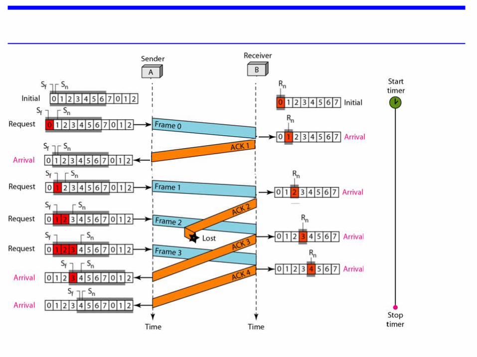
Noisy channel • Stop and wait Automatic Repeat Request:
• Adds a simple error control mechanism to the Stop-and-Wait Protocol.
• When the frame arrives at the receiver site, it is checked and if it is corrupted, it is silently discarded.
• Lost frames are more difficult to handle than corrupted ones.
• The received frame could be the correct one, or a duplicate, or a frame out of order.
• The solution is to number the frames.

• The completed and lost frames need to be resent in this protocol.
• If the receiver does not respond when there is an error, how can the sender know which frame to resend?
• So the sender keeps a copy of the sent frame. At the same time, it starts a timer.
• If the timer expires and there is no ACK for the sent frame, the frame is resent, the copy is held, and the timer is restarted.
• Since the protocol uses the stop-and-wait mechanism, there is only one specific frame that needs an ACK even though several copies of the same frame can be in the network.

• Error correction in Stop-and-Wait ARQ is done by keeping a copy of the sent frame and retransmitting of the frame when the timer expires.
• Since an ACK frame can also be corrupted and lost, it too needs a sequence number.

Sequence Numbers
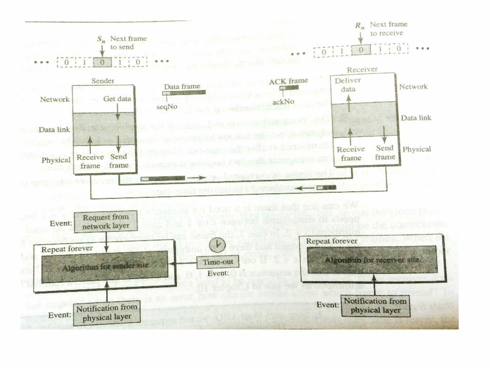
• In Stop-and-Wait ARQ we use sequence numbers to number the frames.
• The sequence numbers are based on modulo-2 arithmetic.
• In modulo-N arithmetic, we use only the integers in the range 0 to N - 1, inclusive.
• In this arithmetic, the modulus N is 2. We can use only 0 and 1

• Assume we have used x as a sequence number, we only need to use x + 1 after that. There is no need for x + 2.
• To show this, assume that the sender has sent the frame numbered x. Three things can happen.

• 1. The frame arrives safely at the receiver site; the receiver sends an acknowledgment. The acknowledgment arrives at the sender site, causing the sender to send the next frame numbered x + 1.
• 2. The frame arrives safely at the receiver site; the receiver sends an acknowledgment, but the acknowledgment is corrupted or lost. The sender resends the frame (numbered x) after the time-out. Note that the frame here is a duplicate. The receiver can recognize this fact because it expects frame x + I but frame x was received.
• 3. The frame is corrupted or never arrives at the receiver site; the sender resends the frame (numbered x) after the time-out.
Acknowledgment Numbers
• The acknowledgment numbers always announce the sequence number of the next frame expected by the receiver.
• For example, if frame 0 has arrived safely, the receiver sends an ACK frame with acknowledgment 1 (meaning
• frame 1 is expected next).
• If frame 1 has arrived safely, the receiver sends an ACK frame with acknowledgment 0 (meaning frame 0 is expected).


• This is very inefficient if our channel is thick and long.
• By thick, we mean that our channel has a large bandwidth; by long, we mean the round-trip delay is long.
• The product of these two is called the bandwidth delay Product

Pipelining
• A new task is begun before the previous task has ended.
• There is no pipelining in Stop-and-Wait ARQ because we need to wait for a frame to reach the destination and be acknowledged before the next frame can be sent.
• However, pipelining is applied to next two protocols- Go-Back-N Automatic Repeat Request

Go-Back-N Automatic Repeat Request
• To improve the efficiency of transmission multiple frames must be in transmitted while waiting for acknowledgment.
• Sequence no – modulo m
• 2m - 1
• In this protocol the sliding window is an theoretical concept that defines the range of sequence numbers.
• The send window is an imaginary box covering the sequence numbers of the data frames which can be in transit.- 2m - 1
• The receive window is an theoretical concept defining an imaginary box of size 1


Go back N sliding window Protocol by Khurram Tanvir.mp4

Selective Repeat Automatic Repeat Request
• Sequence no – modulo m
• 2m - 1
• In this protocol the sliding window is an theoretical concept that defines the range of sequence numbers.
• The send window is an imaginary box covering the sequence numbers of the data frames which can be in transit.- 2m-1
• The receive window is an theoretical concept defining an imaginary box of size 2m-1

Figure Flow diagram for Example 11.8

Selective Repeat sliding Window Protocol by Khurram Tanvir.mp4

Piggybacking• The three protocols discussed are all unidirectional:
• Data frames flow in only one direction although control information such as ACK and NAK frames can travel in the other direction.
• In real life, data frames are normally flowing in both directions:
• from node A to node B and from node B to node A.
• This means that the control information also needs to flow in both directions.
• A technique called piggybacking is used to improve the efficiency of the bidirectional protocols.
• When a frame is carrying data from A to B, it can also carry control information about arrived (or lost) frames from B; when a frame is carrying data from B to A, it can also carry control information about the arrived (or lost) frames from A.


HDLC
• High-level Data Link Control (HDLC) is a bit-oriented protocol for communication over point-to-point and multipoint links.
• HDLC provides two common transfer modes
1. Normal response mode (NRM) 2. Asynchronous balanced mode
(ABM).

Normal Response Mode
• It has one primary station and multiple secondary stations.
• A primary station can send commands, a secondary station can only respond.
• The NRM is used for both point-to-point and multiple-point links.
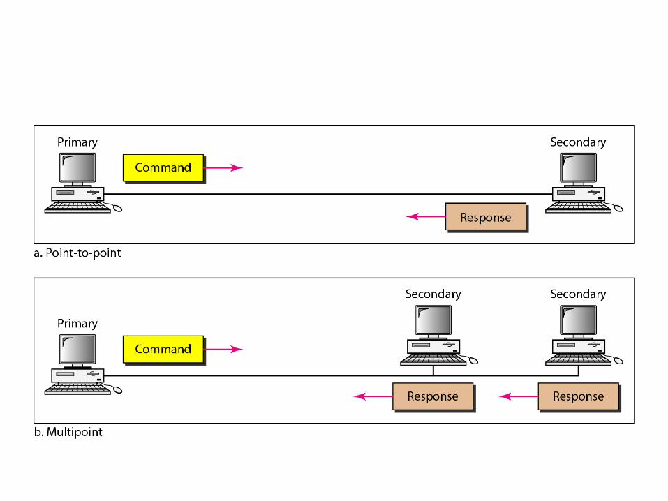

Asynchronous Balanced Mode
• In asynchronous balanced mode (ABM), the configuration is balanced.
• The link is point-to-point, and each station can function as a primary and a secondary.

Frames
• HDLC defines three types of frames1. Information frames (I-frames)2. Supervisory frames (S-frames)3. Unnumbered frames (U-frames).
• Each type of frame serves as an envelope for the transmission of a different type of message.
• I-frames are used to transport user data and control information relating to user data (piggybacking).
• S-frames are used only to transport control information.
• U-frames are reserved for system management.

Frame Format
• Each frame in HDLC may contain up to six fields.
• At beginning flag field, an address field, a control field, an information field, a frame check sequence (FCS) field, and an ending flag field.
• In multiple-frametransmissions, the ending flag of one frame can serve as the beginning flag of the next frame.

Fields Flag field: It is an 8-bit sequence with the bit pattern 01111110 that
identifies both the beginning and the end of a frame.
Address field: It contains the address of the secondary station.
An address field can be 1 byte or several bytes long, depending on the needs of the network.
One byte can identify up to 128 stations
If the address field is only 1 byte, the last bit is always a 1.
If the address is more than 1 byte, all bytes but the last one will end with 0; only the last will end with 1.
Ending each intermediate byte with 0 indicates to the receiver that there are more address bytes to come.

Control field. The control field is 1- or 2-byte segment of the frame used for flow and error control.
Information field. The information field contains the user's data from the network. Its length can vary from one network to another.
FCS field. The frame check sequence (FCS) is the HDLC error detection field. It can be either a 2- or 4-byte.

Control FieldControl Field for I-Frames
• The first bit defines the type of the frame
• . If the first bit of the control field is 0, this means the frame is an I-frame.
• The next 3 bits, called N(S), define the sequence number of the frame.
• With 3 bits, we can define a sequence number between 0 and 7.

• The last 3 bits, called N(R), correspond to the acknowledgment number when piggybacking is used.
• The single bit between N(S) and N(R) is called the P/F bit.
• The P/F field is a single bit with a dual purpose.
• It has meaning only when it is set (bit = 1) and can mean poll or final.
• It means poll when the frame is sent by a primary station to a secondary (when the address field contains the address of the receiver).
• It means final when the frame is sent by a secondary to a primary (when the address field contains the address of the sender).

Control Field for S-Frames
• If the first 2 bits of the control field is 10, this means the frame is an S-frame.
• The last 3 bits, called N(R), corresponds to the acknowledgment number (ACK) or negative acknowledgment number (NAK) depending on the type of S-frame.
• The 2 bits called code is used to define the type of S-frame itself.
• With 2 bits, we can have four types of S-frames, as described below:
• Receive ready (RR). If the value of the code subfield is 00, it is an RR S-frame.
• This kind of frame acknowledges the receipt of a safe and sound frame or group of frames. In this case, the value N(R) field defines the acknowledgment number.

• Receive not ready (RNR). If the value of the code subfield is 10, it is an RNR S-frame.
• This kind of frame is an RR frame with additional functions.
• It acknowledges the receipt of a frame or group of frames, and it announces that the receiver is busy and cannot receive more frames.
• It acts as a kind of congestion control mechanism by asking the sender to slow down. The value of NCR) is the acknowledgment number.

• Reject (REJ). If the value of the code subfield is 01, it is a REJ S-frame.
• This is a NAK frame, but not like the one used for Selective Repeat ARQ.
• It is a NAK that can be used in Go-Back-N ARQ to improve the efficiency of the process by informing the sender, before the sender time expires, that the last frame is lost or damaged.
• The value of NCR) is the negative acknowledgment number.

• Selective reject (SREJ). • If the value of the code subfield is 11,
it is an SREJ S-frame.
• This is a NAK frame used in Selective Repeat ARQ. The value of N(R) is the negative acknowledgment number.

Control Field for U-Frames
• U-frame codes are divided into two sections:
• A 2-bit prefix before the P/F bit and a 3-bit suffix after the P/F bit.
• Together, these two segments (5 bits) can be used to create up to 32 different types of U-frames.
• Some of the more common types are shown in Table
