ccop guideline on the methodologies for selecting ... · ccs-m guideline for co2 storage! !page 1...
TRANSCRIPT

CCOP CO2 Storage Mapping Program (CCS-M) !!CCOP Technical Secretariat - June 25, 2014
CCS-M GUIDELINE FOR CO2 STORAGE! ! PAGE � OF �1 31
CCOP Guideline on the Methodologies for Selecting Geological Carbon Dioxide
(CO2) Storage and Estimation of Storage Capacities

!
CCS-M GUIDELINE FOR CO2 STORAGE! ! PAGE � OF �2 31

Table of Contents !
CONTENTS PAGE
Abbreviations and Acronyms 5
Key Organizations / Agencies in the CCOP Member Countries 6
Acknowledgements 7
1. Introduction 8
2. The Guiding Principle 9
3. Where are we now in CCS? - Geological storage 10
3.1 Status of CCOP Member Countries 12
4. The CCS-M Guideline Development 22
4.1 Characterization Workflow 25
4.2 Quantitative CO 27
5. Guideline Implementation 28
6. Guideline Evaluation and Revision 29
7. References 29
Figures and Tables
Figure 1: Sedimentary basins of East and Southeast Asia identified using the filtering process described in the GEODISC project (Rigg & Al, 2001) (USGS, 2000)
12
Figure 2: Distribution of potential aquifer and reservoir for COstorage, total potential estimated at ~141 BT
17
Figure 3: Outline of sedimentary basins for CCS Projects in Korea
18
Figure 4: Map of the case study area of Malaysia (PETRONAS) 19
Figure 5: Initial results from the CORed River basin in North Vietnam
21
CCS-M GUIDELINE FOR CO2 STORAGE! ! PAGE � OF �3 31

!!!
Figure 6: Techno-Economic Resource-Reserve pyramid for COstorage capacity in geological media within a jurisdiction or geographic region (modified from CSLF, 2005; Bradshaw et al., 2006).!
22
Figure 7: DNV GL CO2Qualstore 25
Figure 8: Schematic showing open aquifer systems versus closed or semi-closed systems (Zhou et al., 2008).
28
Table 1: Result of the recent study of selected oil and gas basins and their CO
14
Table 2: Screening criteria developed by Bachu (2003) modified for CCOP
26
Table 3: Sample input for Monte Carlo simulation for storage capacity estimation
27
CONTENTS PAGE
CCS-M GUIDELINE FOR CO2 STORAGE! ! PAGE � OF �4 31

!!
Abbreviations and Acronyms !
ANP Autoridade Nacional Do Petroleo (Timor Leste) APEC Asia-‐Pacific Economic Coopera<on ASCOPE ASEAN Council on Petroleum BGR German Federal Ins<tute for Geosciences and Natural Resources BGS Bri<sh Geological Survey BPMIGAS Execu<ve Agency for Upstream Oil & Gas Business Ac<vi<es, Indonesia BRGM The French Geological Survey CCOP TS CCOP Technical Secretariat CCOP Coordina<ng CommiMee for Geoscience Programmes in East and Southeast Asia CCS CO2 Capture and Storage CCUS CO2 Capture Use and Storage CCS-‐M CCOP CO2 Storage Mapping Program CGS China Geological Survey CNOOC China Na<onal Offshore Oil Company CNPA Cambodia Na<onal Petroleum Authority CNPC China Na<onal Petroleum Corpora<on CSIRO Australian Commonwealth Science and Industrial Research Organiza<on DGMV Department of Geology and Minerals of Vietnam DGSM Department of Geological Survey and Minerals, Myanmar DGM Department of Minerals and Geology, Lao-‐PDR DMF Department of Mineral Fuels, Thailand DMR Department of Mineral Resources, Thailand DOE Department of Energy, Philippines DPE Department of Petroleum and Energy, PNG ECBM Enhanced Coal Bed Methane EGCFE Expert Group on Clean Fossil Energy (under APEC) EPPM CCOP-‐Norway Program on Enhancing Public Petroleum Management for the CCOP
Member Countries EUR Es<mated Ul<mate Recovery GCCSI Global CCS Ins<tute GHG Greenhouse Gas GSC Geological Survey of Canada GSJ Geological Survey of Japan Gt Gigaton IEA Interna<onal Energy Agency IEAGHG IEA Greenhouse Gas R & D Programme IPG Ins<tute of Petroleum and Geology, Timor-‐Leste JMG Minerals and Geoscience Department, Malaysia ITB Ins<tut Teknologi Bandung, Indonesia JOGMEC Japan Oil, Gas and Metals Na<onal Corpora<on KIGAM Korea Ins<tute of Geoscience & Mineral Resources KNOC Korea Na<onal Oil Corpora<on KOGAS Korea Gas Corpora<on LEMIGAS Research and Development Center for Oil and Gas Technology, Indonesia MC CCOP Member Countries MEMR Ministry of Energy and Mineral Resources, Indonesia MGB Mines and Geosciences Bureau, Philippines MIGAS Directorate General of Oil and Gas, Indonesia
CCS-M GUIDELINE FOR CO2 STORAGE! ! PAGE � OF �5 31

MIME Ministry of Industry, Mines and Energy, Cambodia MLR Ministry of Land and Resources, China MKE Ministry of Knowledge and Economy, Korea MOGE Myanmar Oil and Gas Enterprise MONRE Ministry of Natural Resources and Environment, Lao-‐PDR MOPE Ministry of Petroleum and Energy, Norway Mt Megaton NOEX Nippon Oil Explora<on Ltd NOK Norwegian Kroner NORAD Norwegian Agency for Development Coopera<on NPD Norwegian Petroleum Directorate PEPRIS Petroleum Explora<on & Produc<on Research Ins<tute, SINOPEC PETRAD Interna<onal Programme for Petroleum Management and Administra<on PETRONAS Petroliam Nasional Berhad, Malaysia PNG Papua New Guinea PNOC Philippine Na<onal Oil Company PTTEP PTT (formerly known as Petroleum Authority of Thailand) Explora<on and
Produc<on Company SINOPEC China Petroleum & Chemical Corpora<on SSNR Secretariat of State for Natural Resources, Timor Leste TNO Geological Survey of Netherlands USGS United States Geological Survey VPI Vietnam Petroleum Ins<tute WebGIS Web-‐based Geographic Informa<on System !!!KEY ORGANIZATIONS/AGENCIES IN THE CCOP MEMBER COUNTRIES !China MLR, CGS, SINOPEC, CNOOC, PETROCHINA Cambodia CNPA, MIME Indonesia MEMR, BPMIGAS, MIGAS, LEMIGAS, PERTAMINA, ITB Japan GSJ, JOGMEC Korea MKE, KIGAM, KNOC, KOGAS Lao-‐PDR DGM, MONRE Malaysia PETRONAS, JMG PNG DPE Philippines DOE, PNOC, MGB, ASCOPE Thailand DMF, DMR, PTTEP Timor Leste ANP, SSNR, IPG Vietnam PETROVIETNAM, VPI, DGMV !Observer Country Myanmar MOGE, DGSM !
!!
CCS-M GUIDELINE FOR CO2 STORAGE! ! PAGE � OF �6 31

!Acknowledgements !The CCOP Technical Secretariat is grateful to the Global CCS Ins<tute and Norwegian Ministry of Foreign Affairs for providing funding of the CCS-‐M Program. !Thank you also to the exper<se and dedica<on of some individuals from the Norwegian Petroleum Directorate (NPD), Interna<onal Program for Petroleum Management and Administra<on (PETRAD), Australian Commonwealth Science and Industrial Research Organisa<on (CSIRO), and the Interna<onal Energy Agency (IEA) for guiding the CCS-‐M training courses and workshops that enhanced the understanding of CCOP member countries on CCS. These include experts from the networks of these organiza<ons.
!
CCS-M GUIDELINE FOR CO2 STORAGE! ! PAGE � OF �7 31
!1. IntroducUon
The Coordina<ng CommiMee for Geoscience Programmes in East and Southeast Asia (CCOP) was founded under the auspices of the United Na<ons (ESCAP) in 1966. Ini<ally its remit was to “promote and coordinate the planning and implementa<on of joint prospec<ng programmes and research in Asian offshore and geologically related areas of countries who are members of CCOP”. !In 1987, CCOP became an independent intergovernmental organiza<on, with 13 Member Countries to date: Cambodia, China, Indonesia, Japan, Republic of Korea, Lao PDR, Malaysia, Papua New Guinea, Philippines, Singapore, Thailand, Timor-‐Leste and Vietnam with headquarters in Bangkok, Thailand.
The CCOP region is one of the important areas for fossil fuel explora<on and produc<on -‐ oil, gas and coal resources for energy. As a source for economic prosperity, the CCOP Member Countries have placed great importance and interests in enhancing the sustainable development and produc<on of these resources. In fact, petroleum exploita<on (and also coal) is one of the most important economic ac<vi<es for several of the member countries with significant contribu<on to their GDP. To ini<ate the geological storage of carbon dioxide (CO2) as part of Carbon Capture and Storage (CCS), most of the member countries consider that the sedimentary basins with oil and gas reserves are the priority areas to study, due mainly to the data and knowledge that are available from the oil and gas industry.
To further the region’s understanding of CCS and CO2 storage, a number of the thema<c seminars and workshops were conducted under the Norway – CCOP coopera<on (2008-‐2012). In addi<on, a BGR-‐CO2 GeoNET Workshop was conducted in Bangkok in 2009 that helped the technical personnel in the member countries understand the concepts of CCS and geological storage of CO2 as one mi<ga<on op<on for reducing greenhouse gas (GHG) emissions.
These events resulted in requests from the member countries to the CCOP Technical Secretariat to implement a capacity building program on CCS with the objec<ve of mapping the poten<al geological storage areas in the region. This program has been implemented and a key part of the capacity building is the development of a CCOP Methodology Guideline for the selec<on of geological CO2 storage sites and es<ma<on of CO2 storage capaci<es, referred to as CCS-‐M Guideline or simply Guideline in this report.
The goals of CCS-‐M are to enable the government organiza<ons in the CCOP Member Countries responsible for mapping the geological storage of CO2 to:
• Provide a high level overview of the poten<al for large-‐scale CO2 storage,
CCS-M GUIDELINE FOR CO2 STORAGE! ! PAGE � OF �8 31
• Enhance the member countries capacity and capability in the assessment of geological sites for the safe and long-‐term storage of CO2, and
• Increase their understanding of the poten<al of CO2 for enhanced oil and gas recovery.
During the 60th CCOP Steering CommiMee Mee<ng (March 26, 2014 Ubon Ratchathani, Thailand), CCOP and the Global CCS Ins<tute signed a Sponsorship Agreement for the implementa<on of the CCOP carbon dioxide (CO2) Storage Mapping Program (CCS-M) Facilita<on Phase or Year 1. In December 2013, the Norwegian Ministry of Foreign Affairs thru the Royal Norwegian Embassy -‐ Jakarta provided addi<onal funding to the Program.
This document will introduce the guiding principle adopted by CCOP, give a brief overview of the current status of storage capacity assessments per CCOP country, provide some details regarding the development of the Guideline, such as the workflow and adopted capacity es<ma<on calcula<on methods. Finally, this document introduces how this Guideline will be further implemented in each CCOP country and reviewed.
!2. The Guiding Principle
Carbon Capture and Storage (CCS) is a term that encompasses a chain of technologies that can be used to capture CO2 from point sources, such as power plants and other industrial facili<es; compress the captured CO2 into a liquid-‐like dense phase; transport it (mainly by pipeline) to suitable loca<ons; and safely inject it into deep subsurface geological forma<ons for isola<on from the atmosphere. CCS is a cri<cal op<on in the pormolio of solu<ons available to combat climate change, because it allows for significant reduc<ons in CO2 emissions from fossil-‐based plants, enabling it to be used as a bridge to a sustainable energy future.
At the star<ng point for the development of the Guideline, the member countries broadly agreed that CCS will most likely be needed to achieve the magnitude of CO2 emissions reduc<on required to stabilize and reduce atmospheric concentra<ons of Greenhouse Gases (GHGs). The oil and gas industry’s experience in assessing subsurface characteris<cs, and CO2 injec<on for enhanced oil recovery over the previous decades gives us the confidence that large scale storage of CO2 in the subsurface can be undertaken.
The objec<ves of developing the Guideline are to provide a tool and useful reference for the CCOP member countries for their own na<onal CO2 storage mapping. This will assist the technical personnel in the CCOP Member Countries who will be tasked to provide a high level overview of the poten<al for large-‐scale CO2 storage in their country and understand the emission reduc<on poten<al of CCS. Also, the decision makers in the member countries need to understand the amount of CO2 that can be safely stored in the subsurface and the geographical distribu<on of storage resources.
CCS-M GUIDELINE FOR CO2 STORAGE! ! PAGE � OF �9 31
The CO2 storage capacity es<mate parameters in this guideline will not include economic or regulatory constraints; only physical constraints are used in the guideline to define the accessible part of the subsurface. However, member countries may apply economic or other constraints in their own assessments. If possible also, these constraints may be added to the Guidelines in the future.
CCOP also recognizes that es<mates of storage capaci<es need to be made using reliable and consistent methods. The two training courses recently conducted in the CCS-‐M Program, T1 (Bali, April 2013), T2 (Bangkok, August 2014) and T4 (Penang, May 2014), have highlighted some of the methodologies used in many countries and organiza<ons. There is a general agreement, that we will use the works done by others as a basis and specifically the IEA Report (2013) “Methods to assess geologic CO2 storage capacity: status and best prac<ce” will be used as reference for the development of the CCOP Guideline. Based on the feedback from the par<cipant of the 3 training courses, there is a need to learn in greater depth, how the characteriza<on of reservoirs are performed and how the es<ma<on of storage capaci<es, par<cularly CO2 injec<vity and calcula<on of storage efficiency values are calculated. In CCS-‐M ac*vi*es the code for training course is “T”, seminar “S”, workshop “W” and case study “C”, wherein T1 means training course 1.
The above-‐men<oned IEA report is an outcome of workshops that were conducted in 2011 and in 2012, which brought together experts from na<onal geological survey organiza<ons United States Geological Survey (USGS), Geoscience Australia, German Federal Ins<tute for Geosciences and Natural Resources (BGR), Bri<sh Geological Survey (BGS), Geological Survey of Netherlands (TNO) and Geological Survey of Canada (GSC) to review the geologic CO2 storage assessment methodologies and make recommenda<ons on how to harmonize CO2 storage assessment worldwide.
Another important references are the CO2CRC report (2008) “Storage Capacity Es<ma<on, Site Selec<on and Characteriza<on for CO2 Storage Projects” which was highlighted in the CCS-‐M T1 -‐ Bali and the CO2 Storage Atlases published by Norway, USGS and Australia.
!3. Where are we now in CCS – geological storage?
CCS capacity development is also reflected in the level of economic development of each CCOP member country. CCS-‐related research ac<vi<es in Japan, China and Korea are on-‐going ac<vi<es of their geological surveys and na<onal research ins<tutes. These countries have also gained a lot of knowledge in CCS and in par<cular CO2 storage through their par<cipa<on in various CCS projects outside the CCOP region, and therefore, are compara<vely advanced compared to the other member countries.
Indonesia, Philippines, Thailand and Vietnam were beneficiaries of the Asian Development Fund (ADB)-‐funded Project “Exploring the poten<al for CCS in SE Asia”, that was completed in late 2011 and resulted in an enhanced level of knowledge about CCS, par<cularly on the
CCS-M GUIDELINE FOR CO2 STORAGE! ! PAGE � OF �10 31

geological storage aspect. The same ADB Project resulted in a report “Prospects for CCS in Southeast Asia (Sep 2013)” and is also used as a reference in this report.
Malaysia is at about the same level as the 4 (four) men<oned countries and led by its na<onal oil company – PETRONAS, together with PERTAMINA (Indonesia), these 2 companies ini<ated the crea<on of a CCS task force within the Associa<on of Southeast Asian Na<ons (ASEAN) Council on Petroleum (ASCOPE) for capacity building purposes and to look into the feasibility of CCS pilot projects for CO2 storage and enhancing oil and gas recovery using CO2 (CO2 EOR). The other CCOP member countries can be described as s<ll in an early stage of CCS knowledge development.
In 2003, the Expert Group on Clean Fossil Energy (EGCFE) under the Asia-‐Pacific Economic Coopera<on (APEC), ini<ated a mul<-‐phase carbon capture and storage program led by Canada. The CCS ini<a<ve was designed to assist non-‐industrialized APEC members (many CCOP countries are also members of APEC) to successfully iden<fy, evaluate and develop CO2 capture and geological storage opportuni<es in their economies. The implementa<on was done in 2 themes, as follows:
Theme I – studies to assess the poten<al for CO2 capture and geological storage in the APEC region
Theme II – ac<vi<es to raise awareness of and build capacity in CO2 capture and geological storage in APEC.
Theme I iden<fied major sources of CO2 emissions and provided a high-‐level ranking of sedimentary basins in China and South East Asia according to low and no “prospec<vity” potential for CO2 storage. The types of geological storage reservoirs examined included deep saline forma<ons, depleted oil and gas fields and deep coal seams. !!!!!!!!!!!
CCS-M GUIDELINE FOR CO2 STORAGE! ! PAGE � OF �11 31

!!!!!!!!!!!!!!!!!!!Figure 1: Sedimentary basins of East and Southeast Asia iden*fied using the filtering process described in the GEODISC project (Rigg & Al, 2001) (USGS, 2000) !3.1 Status of CCOP Member Countries in CCS – geological storage potenUal
This sec<on gives an overview of some of the informa<on available on CCS developments in selected countries that have on-‐going ac<vi<es related to mapping of geological storage.
1. China
China is the most populated country and is currently the second largest economy in the world, an economy that has grown at a tremendous pace for the last 20 years. The total energy consump<on of China is dominated by fossil fuel with coal and oil/gas contribu<ng ~93% (USIA, 2008), and this will con<nue to be the case in the foreseeable future. Emissions from energy-‐related ac<vi<es account for ~90% of China’s total emissions.
Early this year (2013), China’s Na<onal Development and Reform Commission issued a document to Promote Carbon Capture U<liza<on (CCSUS) and Storage Pilot and Demonstra<on. This document notes that promo<ng CCUS is an important task in the 12th Five-‐Year Work Plan on Controlling GHG Emissions approved by the State Council, which clearly indicates the need to develop CCS pilot and demonstra<on plants in a range of industries (GCCSI, 2013).
CCS-M GUIDELINE FOR CO2 STORAGE! ! PAGE � OF �12 31

As learned from the country report of SINOPEC during the CCS-‐M training course 2 (T2, August 2013), China has done some studies on the poten<al of geological storage. A total of ~860 research and mapping studies have been conducted targe<ng onshore and offshore basins. The es<mated poten<al capacity from these studies is as follows:
• Saline aquifer – 1,435 gigatons (Gt)
• Petroliferous (oil and gas) basins – 7.8 Gt
• Coal beds – 12 Gt 1
The same report also showed that the Southeast (SE) China fold belt had only small con<nental basins with limited CO2 storage capacity. However, the offshore basins are large and of high poten<al for CO2 storage and may account for >50% of the total storage poten<al. These basins also match well with the large emission sources along the coast of SE China. The depleted oil & gas fields are considered as early opportuni<es for geological storage. By u<lizing exis<ng data, oil & gas plamorms and other facili<es, the cost of offshore CO2 injec<on may be greatly reduced.
China will host a case study on CO2 storage and use of CO2 for EOR in CCS-‐M. The par<cipa<on of China in CCS-‐M is led by SINOPEC Explora<on and Produc<on Research Ins<tute (PEPRIS).
2. Indonesia
Indonesia is the second most populated country in CCOP and 4th most populated country in the world. Fossil fuels dominate Indonesia’s energy supply, and will con<nue to do so in the foreseeable future. Similar to the growing economic performance, the emission trend is also growing at an alarming rate with land use/forestry and peat fire accoun<ng for 62% and energy at 22% of the total emission (GCCSI 2013).
Indonesia is commiMed to reduce its GHG emissions by adop<ng the Na<onal Ac<on Plan Addressing Climate Change (RAN-‐PI) through Presiden<al Decree No. 61/2011. The government believes that current efforts are s<ll insufficient to achieve the target of 26% CO2 emission abatement target by 2020, thus it is implemen<ng programs to focus on
• Energy mix improvements
• Switch to less carbon intensive fuels
• Renewable resource deployment.
CCS-M GUIDELINE FOR CO2 STORAGE! ! PAGE � OF �13 31
However, it should be noted that storage in coal seams is technically less mature than 1
storage in depleted oil and gas fields, or saline aquifers.

Indonesia is also planning to implement a strategy on energy security with CCS in conjunc<on with:
• Enhanced Oil Recovery (EOR) – using (5-‐8) opera<onal projects around the world as case studies
• Coal to Liquid and Coal to Gas
• Biomass.
As presented during the CCS-‐M Launching Seminar (April 2013), various joint studies related to CCS implementa<on in Indonesia were conducted since 2003 with interna<onal companies and organiza<ons. The general findings of these studies with regards to Indonesia’s CO2 storage poten<al are as follows:
• Oil and Gas upstream sector is the most suitable for near-‐term deployment of CCS, and
• More than 600 Mt of CO2 can be stored in depleted oil and gas reservoirs while
the latest study indicates South and Central Sumatra may have a theore<cal storage capacity of >10 GT CO2.
Table 1: Results of the recent study of selected oil and gas basins in Indonesia: their CO2 storage capaci*es and storage suitability score (LEMIGAS, 2011).
Basin EffecUve Storage Capacity (Mt)
Storage Suitability Score (%)
Kutei 0.5 91
Tarakan 129 91
South Sumatra 144 76
Seram -‐ 74
NW Java 7 72
Barito 10 72
Central Sumatra 229 72
North Sumatra -‐ 70
Salawa< 18 70
NE Java 19 68
CCS-M GUIDELINE FOR CO2 STORAGE! ! PAGE � OF �14 31

Main criteria considered in the LEMIGAS study, and that were used to obtain the ‘Storage Suitability Score’ in the table above were: !
1. Reservoirs having been the object of good characteriza<on
2. Favorable and well-‐known geological structure
3. There is poten<al to reuse exis<ng infrastructure.
The higher the percentage score, the more likely it will be suitable for CO2 storage projects.
The ADB report (Sept 2013) es<mated the theore<cal storage capacity for saline aquifers of 7.7 Gt and effec<ve storage capacity of 0.9 Gt from oil and gas fields in South Sumatra basin. The study was conducted in just 1 of over 60 sedimentary basins in Indonesia.
The par<cipa<on of Indonesia in CCS-‐M is represented by Geological Agency Indonesia, LEMIGAS and ITB.
3. Japan
Japan is currently the third largest economy in the world, auer the USA and China. Although Japan consumes a large amount of energy it is almost 100% reliant on imported energy. Japan’s energy sector accounts for over 90% of the total GHG emission.
The framework for CCS research in Japan is implemented mainly by the Ministry of Economy, Trade and Industry (METI) –providing budget and subsidy for research and development (R & D) and demonstra<on of CCS. Japan has done several studies and evalua<on on greenhouse gas (GHG) emission sources and matching the distribu<on of poten<al reservoir for CO2 storage which is es<mated at ~141 Bt.
R & D ac<vi<es on CCS which included various storage op<ons, e.g. ocean storage, and Enhanced Coal Bed Methane (ECBM), started in late 1980s.
From July 2003 to January 2005, 10,400 tons of CO2 were injected into saline acquifer 1,110 meters below the ground surface of Iwanohara, Nagaoka site, Niigata Prefecture. Japan’s Research Ins<tute of Innova<ve Technology for the Earth (RITE), s<ll con<nue various on-‐site measurements of wells to understand CO2 behavior auer the end of injec<on. For that reason, its monitoring results have drawn great aMen<on from all over the world. Many of these studies are shared to CCOP member countries through CCS-‐M.
Auer the successful geological storage test in Nagaoka and the preliminary evalua<on of storage poten<al in Japan, the priority of R & D has been shiued to “sub-‐seabed” geological storage. Current R & D ac<vi<es include various capture op<ons (chemical absorp<on, membrane, and oxyfuel), monitoring techniques, and long-‐term computa<onal simula<ons of CO2 plume in a reservoir.
In August 2009, the Ministry of Economy, Trade and Industry (METI) compiled a guideline, “For safe opera<on of a CCS demonstra<on project”. This guideline is a standard to be
CCS-M GUIDELINE FOR CO2 STORAGE! ! PAGE � OF �15 31

followed from the safety and environment viewpoints in implemen<ng a large-‐scale CCS demonstra<on project.
In April 2012, METI ini<ated a full-‐chain CCS demonstra<on project in Tomakomai, Hokkaido. They commissioned its delivery to Japan CCS Co., Ltd., which was established in May 2008 for implemen<ng CCS demonstra<on in Japan. Prior to the launch of the project, the company had carried out feasibility studies for integrated CCS systems and geological surveys at a couple of candidate fields, including Tomakomai, for the demonstra<on and had completed basic designing of the demonstra<on in Tomakomai by 2011. Japan’s road map for CO2 storage plans is as follows:
• 2016 -‐2020: Start of industrial ini<a<ve at ~250,000 T/Year
• 2020: Commercial projects at >1M T/Year.
!
CCS-M GUIDELINE FOR CO2 STORAGE! ! PAGE � OF �16 31

! !
!!!!!!!!!!!!!!
!!Figure 2: Distribu*on of poten*al aquifer and reservoir for CO2 storage, total poten*al es*mated at ~141 BT (CCS-‐M T4 country report presenta*on, May 2014)
Japan’s par<cipa<on in the CCS-‐M program is represented by the Geological Survey of Japan, AIST.
4. Korea
Korea has seen very rapid development over the last several decades and its economy is heavily dependent on interna<onal trade. In 2010, Korea was the sixth largest exporter and tenth largest importer in the world. Korea imports nearly all its energy resources, including oil and natural gas and coal. According to IEA (2009), Korea was ranked eighth among the world’s top emiMers of CO2 in the world.
CCS-M GUIDELINE FOR CO2 STORAGE! ! PAGE � OF �17 31
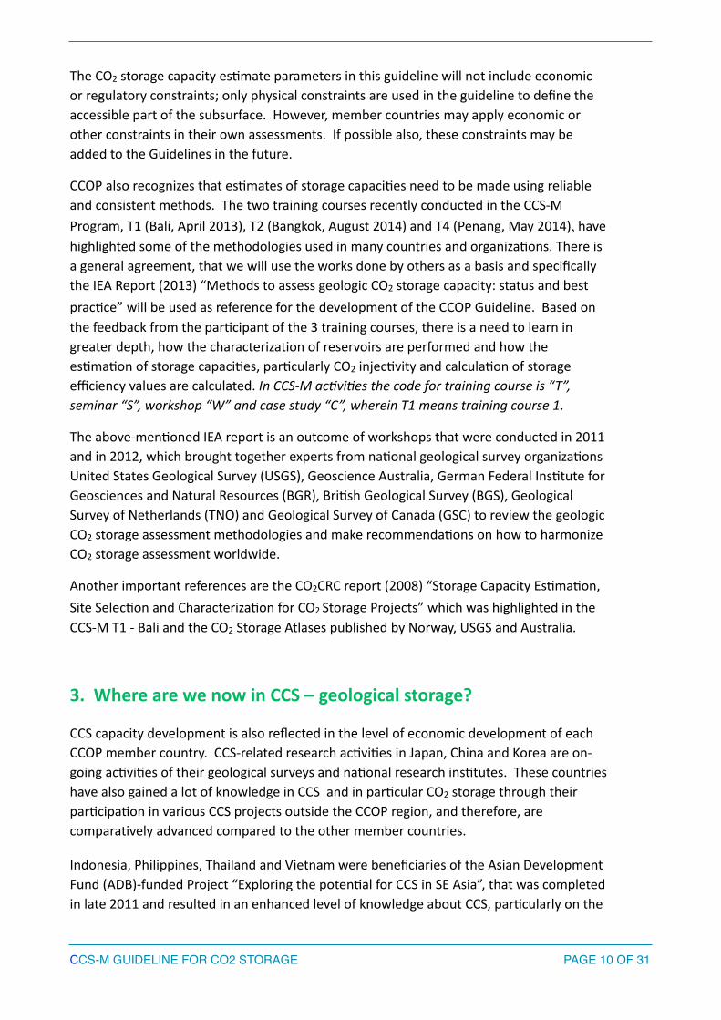
As reported by Korea Ins<tute of Geoscience & Mineral Resources (KIGAM) during CCS-‐M training course 4 (T4, May 2014) characteriza<on of geological basin poten<al for CO2 storage is currently an on-‐going ac<vity. Under the Korea CCS Roadmap “Prac<cal use of CCS technology by 2020”, KIGAM will be leading CO2 storage researches from site selec<on, injec<on and monitoring, through to closure of CCS projects. Site selec<on and drilling ac<vi<es will be conducted during the period 2015-‐2017 with a vision of star<ng a small-‐scale pilot test in 2015 to run un<l 2020. The main components of KIGAM’s R & D are as follows:
1. Site screening and geological characteriza<ons;
2. Development of CO2 injec<on system;
3. Development of CO2 monitoring technologies; and
4. Mineral carbona<on using industrial mineral wastes and natural minerals
Figure 3: Outline of sedimentary basins for CCS Projects in Korea (CCS-‐M T4 country report presenta*on, May 2014)
Korea’s par<cipa<on in the CCS-‐M Program is represented by KIGAM.
!
CCS-M GUIDELINE FOR CO2 STORAGE! ! PAGE � OF �18 31
Ulleong BGunsan B
Gyeongsang B

5. Malaysia
When compared with other developing countries within the Associa<on of Southeast Asian Na<ons (ASEAN), the carbon intensity of Malaysia’s economy is rela<vely high. Malaysia is commiMed in addressing its steadily increasing emissions profile and has tasked its Ministry of Natural Resources and Environment with the responsibility of developing an emissions reduc<on roadmap to iden<fy how this target can be achieved. Malaysia has established a significant renewable energy pormolio to address this. The Government of Malaysia is exploring many different mi<ga<on and energy efficiency op<ons, including CCS. !According to a United States Geological Survey (USGS) assessment undertaken in 2000, Malaysia’s total hydrocarbon pore space is considerable. The es<mate for Malaysia’s ‘known’ (cumula<ve produc<on plus reserves) hydrocarbons in the Malay and Greater Sarawak basins is ~4.4 billion barrels (bbls) of oil and ~125 trillion cubic feet (TCF) of gas. !The Malay basin is located close to 76% of Malaysia’s CO2 sources. Data gathered by the USGS in 2000 from hydrocarbon field data suggests there is ouen good porosity and permeability in the Malay basin. !The USGS es<mate of the Malay basin’s poten<al to store CO2 is ~ 4.3 Gt. The same assessment also noted that the deple<on status of specific fields is unknown and that this pore space will not be available for storage for some <me. !Malaysia will host a case study on CO2 storage in Sarawak Basin for the CCS-‐M. Malaysia’s par<cipa<on in the CCS-‐M Program is represented by PETRONAS. !!!!!!
!!
CCS-M GUIDELINE FOR CO2 STORAGE! ! PAGE � OF �19 31

!Figure 4: Map of the case study area of Malaysia (CCS-‐M T4 country report
presenta<on, May 2014).
6. Philippines !The Philippines is one of the focus countries of the above-‐men<oned ADB study. The ADB report (September 2013) es<mated theore<cal capacity from saline aquifers in the Philippines at 22.7 Gt and effec<ve capacity from oil and gas fields at 0.3 Gt. These es<mates are based on 2 out of 16 sedimentary basins covered by the study. !
7. Thailand
Thailand is an emerging economy and is presently a newly industrialized country. The economy of Thailand is heavily export-‐dependent. According to the UN Sta<s<cs report (2010), Thailand is the 22nd largest GHG emiMer in the world at 286 MT/Year, 54% from energy sector, 19% from agriculture sector, and 6% from industrial sector. The 2013-‐2050 Climate Change Master Plan (drau) of Thailand is an integrated plan with the goal of sustainable development. A key intermediate milestone in this Plan is to reduce 7-‐20% of CO2 emission in energy and transport sectors by 2021. The long-‐term objec<ves are to reduce CO2 emission/GDP and to promote low CO2 industries.
More than 90% is located offshore in the Gulf of Thailand where major oil and gas produc<on is also located. The ADB report (September 2013) es<mated the theore<cal storage capacity of saline aquifers at 8.9 Gt and effec<ve storage capacity of oil and gas fields at 1.4 Gt. This es<mate is based on the study conducted on 10 of 94 sedimentary basins in Thailand.
Thailand’s par<cipa<on in the CCS-‐M Program is represented by Department of Minerals Fuels (DMF).
8. Vietnam
Vietnam is among the oil producing member countries of CCOP. Though oil and gas is a rela<vely new sector in Vietnam, it is currently the 3rd largest oil producer in SE Asia. Manufacturing, informa<on technology and high-‐tech industries now form a large and fast-‐growing part of the economy. The main source of CO2 emissions (~90%) are the power and gas processing plants.
In 2009, the French Geological Survey (BRGM) and Vietnam Department of Geology and Mineral Resources (DGMV) publish the report ”Where is the capacity of CO2 storage in Vietnam?”. Also in the same year, Vietnam Petroleum Ins<tute (VPI), PetroVietnam, Japan Oil Gas and Metal Corpora<on (JOGMEC) and Nippon Oil Explora<on Ltd (NOEX) implemented the Project ”Studying the ability o fusing CO2 to enhance oil recovery in
CCS-M GUIDELINE FOR CO2 STORAGE! ! PAGE � OF �20 31

offshore oil fields in Vietnam to partly respond with climate change”. In June 2013, Vietnam Ins<tute of Geosciences and Mineral Resources (VIGMR) ini<ated a study looking into the poten<al and the technological solu<ons for CO2 storage in geological forma<ons in Northern Vietnam.
The ADB report (September 2013) es<mated the theore<cal storage capacity of Vietnam’s saline aquifer at 10.4 Gt and effec<ve capacity for oil and gas fields at 1.4 Gt. This es<mates is based on the study conducted on 6 out of 8 sedimentary basins in Vietnam.
!
Figure 5: Initial results from the CO2 storage potential study of the Red River basin in North Vietnam.
Vietnam’s par<cipa<on in the CCS-‐M Program is represented by PetroVietnam and VIGMR.
CCS-M GUIDELINE FOR CO2 STORAGE! ! PAGE � OF �21 31
Sandstone layers: thickness: 10-30m, porosity: 5-30%; !
115 coal beds (lignite)

9. Other Member Countries (Cambodia, Lao-‐PDR, Papua New Guinea, and Timor-‐Leste and Myanmar (observer country) !
The remainder of the CCOP member countries par<cipa<ng in the CCS-‐M program has no current CCS or CO2 geological storage ac<vi<es. Their GHG emission reduc<on strategy is focused mainly on energy efficiency and other technologies. Papua New Guinea, Timor-‐Leste and Myanmar are currently producing oil and gas and may offer opportuni<es for CO2 storage poten<al in the future.
!4. The CCS-‐M Guideline Development
One of the outcomes of the CCS-‐M Program will be the development of the Geologic CO2
Storage atlas (CCOP Atlas) of the CCOP region. The CCOP Atlas will give an overview of reservoir forma<ons within relevant burial depth in defined areas. . An atlas is based on a large set of high quality data. In areas with poor data coverage, other methods of assessment, e.g. probabilis<c methods could be applied.
The CCOP par<cipa<ng members learned that there are two different types of classifica<on systems used in the CO2 storage atlases that are currently published: the first type comprises a variety of capacity or matura<on pyramids, the second approach tries to set up a system analogue to the resource-‐reserves concept used in the petroleum industry. The first one, the classifica<on concept of a ‘capacity pyramid’, is widely used in the CO2 community. Most widespread is the classical storage resource pyramid, as suggested originally by Bachu (2007).
!!!!!!!!!Figure 6: Techno-‐Economic Resource-‐Reserve pyramid for CO2 storage capacity in geological media within a jurisdic*on or geographic region (modified from CSLF, 2005; Bradshaw et al., 2006).
CCS-M GUIDELINE FOR CO2 STORAGE! ! PAGE � OF �22 31
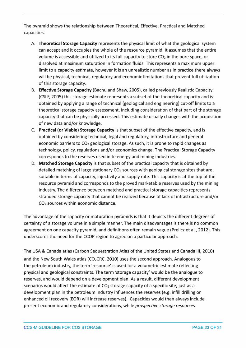
The pyramid shows the rela<onship between Theore<cal, Effec<ve, Prac<cal and Matched capaci<es.
A. TheoreUcal Storage Capacity represents the physical limit of what the geological system can accept and it occupies the whole of the resource pyramid. It assumes that the en<re volume is accessible and u<lized to its full capacity to store CO2 in the pore space, or dissolved at maximum satura<on in forma<on fluids. This represents a maximum upper limit to a capacity es<mate, however it is an unrealis<c number as in prac<ce there always will be physical, technical, regulatory and economic limita<ons that prevent full u<liza<on of this storage capacity.
B. EffecUve Storage Capacity (Bachu and Shaw, 2005), called previously Realis<c Capacity (CSLF, 2005) this storage es<mate represents a subset of the theore<cal capacity and is obtained by applying a range of technical (geological and engineering) cut-‐off limits to a theore<cal storage capacity assessment, including considera<on of that part of the storage capacity that can be physically accessed. This es<mate usually changes with the acquisi<on of new data and/or knowledge.
C. PracUcal (or Viable) Storage Capacity is that subset of the effec<ve capacity, and is obtained by considering technical, legal and regulatory, infrastructure and general economic barriers to CO2 geological storage. As such, it is prone to rapid changes as technology, policy, regula<ons and/or economics change. The Prac<cal Storage Capacity corresponds to the reserves used in te energy and mining industries.
D. Matched Storage Capacity is that subset of the prac<cal capacity that is obtained by detailed matching of large sta<onary CO2 sources with geological storage sites that are suitable in terms of capacity, injec<vity and supply rate. This capacity is at the top of the resource pyramid and corresponds to the proved marketable reserves used by the mining industry. The difference between matched and prac<cal storage capaci<es represents stranded storage capacity that cannot be realized because of lack of infrastructure and/or CO2 sources within economic distance. !
The advantage of the capacity or matura<on pyramids is that it depicts the different degrees of certainty of a storage volume in a simple manner. The main disadvantages is there is no common agreement on one capacity pyramid, and defini<ons ouen remain vague (Prelicz et al., 2012). This underscores the need for the CCOP region to agree on a par<cular approach. !The USA & Canada atlas (Carbon Sequestra<on Atlas of the United States and Canada III, 2010)
and the New South Wales atlas (CO2CRC, 2010) uses the second approach. Analogous to the petroleum industry, the term ‘resource’ is used for a volumetric es<mate reflec<ng physical and geological constraints. The term ‘storage capacity’ would be the analogue to reserves, and would depend on a development plan. As a result, different development scenarios would affect the es<mate of CO2 storage capacity of a specific site, just as a development plan in the petroleum industry influences the reserves (e.g. infill drilling or enhanced oil recovery (EOR) will increase reserves). Capaci<es would then always include present economic and regulatory considera<ons, while prospec*ve storage resources
CCS-M GUIDELINE FOR CO2 STORAGE! ! PAGE � OF �23 31

would be mainly based on geological parameters. The USA Department of Energy (DOE) stresses the importance of a common terminology that can be used for making regulatory and business decisions.
Most CCOP member countries have displayed a preference for the (first) ‘pyramid’ classifica<on approach.
CCOP member countries, through CCS-‐M training courses 1, 2, and 4 (T1, T2 and T4) have gained some knowledge on the methodologies used in Australia (CO2CRC and Geoscience Australia) Norway (NPD and Statoil) and USA (USGS). The T2 and T4 workshops resulted in the following consensus from the par<cipants:
• Type of assessment and coverage – Onshore and offshore areas
• Scale: High level assessment (basin scale)
o Saline aquifers: to be assessed at basin level and offer theore<cal storage es<mates. When more detailed data becomes available, es<mates of effec<ve or prac<cal geological storage capacity can be developed depending on the extent of the data available.
o Depleted hydrocarbon (oil and gas) fields: storage es<mates represent the effec<ve storage capacity and based on the es<mated ul<mate recovery (EUR) of oil and gas. The EURs are converted to CO2 storage es<mates by using forma<on volume factors and the density of the CO2 at reservoir condi<ons. The scale of the data also influences the certainty of the es<mates.
• Es<ma<on methods: probabilis<c (determinis<c es<ma<on will be used if sufficient data is available and/or the basin/field is considered mature)
• Use of the Geographic Informa<on System (GIS) mapping system to locate the storage sites – a system that will provide the possibility for member countries to update their informa<on and view updates from other member countries online. This will leverage on past & exis<ng GIS projects in CCOP (WebGIS).
• Support from Member Countries – available data (public domain data) and exper<se.
The member countries also agreed not to include in the storage assessment the reservoir that is known to contain potable water and those within an area of poten<al petroleum migra<on.
!!!!
CCS-M GUIDELINE FOR CO2 STORAGE! ! PAGE � OF �24 31
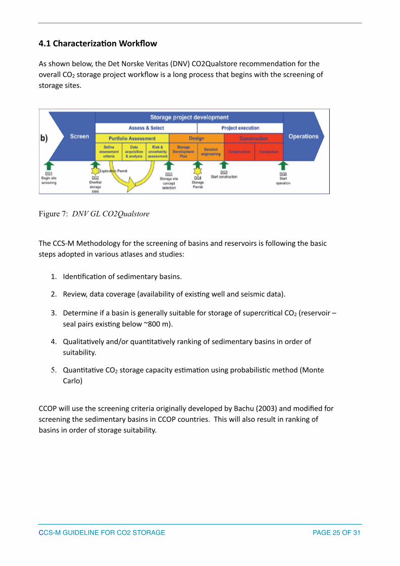
4.1 CharacterizaUon Workflow !As shown below, the Det Norske Veritas (DNV) CO2Qualstore recommenda<on for the overall CO2 storage project workflow is a long process that begins with the screening of storage sites.
!Figure 7: DNV GL CO2Qualstore !!The CCS-‐M Methodology for the screening of basins and reservoirs is following the basic steps adopted in various atlases and studies: !
1. Iden<fica<on of sedimentary basins.
2. Review, data coverage (availability of exis<ng well and seismic data).
3. Determine if a basin is generally suitable for storage of supercri<cal CO2 (reservoir – seal pairs exis<ng below ~800 m).
4. Qualita<vely and/or quan<ta<vely ranking of sedimentary basins in order of suitability.
5. Quan<ta<ve CO2 storage capacity es<ma<on using probabilis<c method (Monte Carlo)
!CCOP will use the screening criteria originally developed by Bachu (2003) and modified for screening the sedimentary basins in CCOP countries. This will also result in ranking of basins in order of storage suitability. !!!!!!
CCS-M GUIDELINE FOR CO2 STORAGE! ! PAGE � OF �25 31
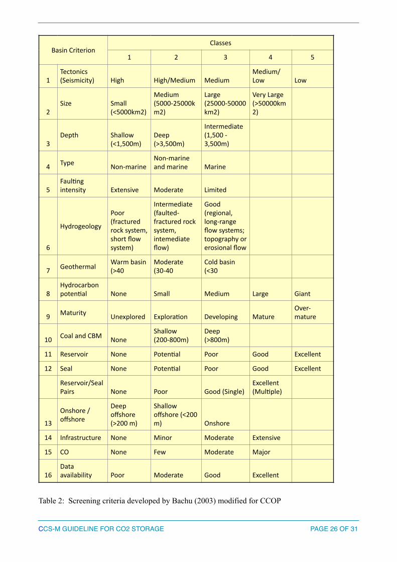
!Table 2: Screening criteria developed by Bachu (2003) modified for CCOP
Basin CriterionClasses
1 2 3 4 5
1Tectonics (Seismicity) High High/Medium Medium
Medium/Low Low
2Size Small
(<5000km2)
Medium (5000-‐25000km2)
Large (25000-‐50000km2)
Very Large (>50000km2)
3Depth Shallow
(<1,500m)Deep (>3,500m)
Intermediate (1,500 -‐ 3,500m)
4 Type Non-‐marineNon-‐marine and marine Marine
5Faul<ng intensity Extensive Moderate Limited
6
Hydrogeology
Poor (fractured rock system, short flow system)
Intermediate (faulted-‐fractured rock system, intemediate flow)
Good (regional, long-‐range flow systems; topography or erosional flow
7 Geothermal Warm basin (>40
Moderate (30-‐40
Cold basin (<30
8Hydrocarbon poten<al None Small Medium Large Giant
9 Maturity Unexplored Explora<on Developing MatureOver-‐mature
10 Coal and CBM NoneShallow (200-‐800m)
Deep (>800m)
11 Reservoir None Poten<al Poor Good Excellent
12 Seal None Poten<al Poor Good Excellent
Reservoir/Seal Pairs None Poor Good (Single)
Excellent (Mul<ple)
13
Onshore / offshore
Deep offshore (>200 m)
Shallow offshore (<200 m) Onshore
14 Infrastructure None Minor Moderate Extensive
15 CO None Few Moderate Major
16Data availability Poor Moderate Good Excellent
CCS-M GUIDELINE FOR CO2 STORAGE! ! PAGE � OF �26 31

4.2 QuanUtaUve CO2 Storage Capacity EsUmaUon
In order to measure ‘theore<cal storage capacity’ the general concept is that first the pore volume of the reservoir forma<on is calculated, by mul<plying the available rock volume with the average porosity. Next, this volume is mul<plied by the amount of pure CO2 (density at reservoir condi<ons), to determine the mass of CO2 that can be stored. Then an efficiency factor (E: 0.1 – 5%) is applied in order to account for a number of geological and physical constraints that limit the volume that can actually be u<lized for CO2 storage within an aquifer.
Considering the nature of regional assessments, some calcula<on parameters (especially porosity values) cannot be determined accurately for each storage structure. The calcula<ons are therefore partly based on analogues. In order to account for parameter uncertain<es on the calculated storage capaci<es, Monte Carlo simula<ons are performed. For each poten<al storage area at least ~5000 runs of simula<ons are performed. The results are presented as sta<s<cal distribu<on: P10 – P50 – P90.
!
�
Table 3: Sample input for Monte Carlo simula<on for storage capacity es<ma<on (CCS-‐M T2 workshop, August 2013)
The Norwegian Petroleum Directorate (NPD) reported that the theore<cal storage efficiency (E) calculated from pore volume in a closed aquifer is typically 0.5 to 1% because of pressure build-‐up. Higher values for E in depleted oil and gas fields or if forma<on water is produced. In half-‐open aquifers a value of 4% is regarded as typical, but should be tested
CCS-M GUIDELINE FOR CO2 STORAGE! ! PAGE � OF �27 31
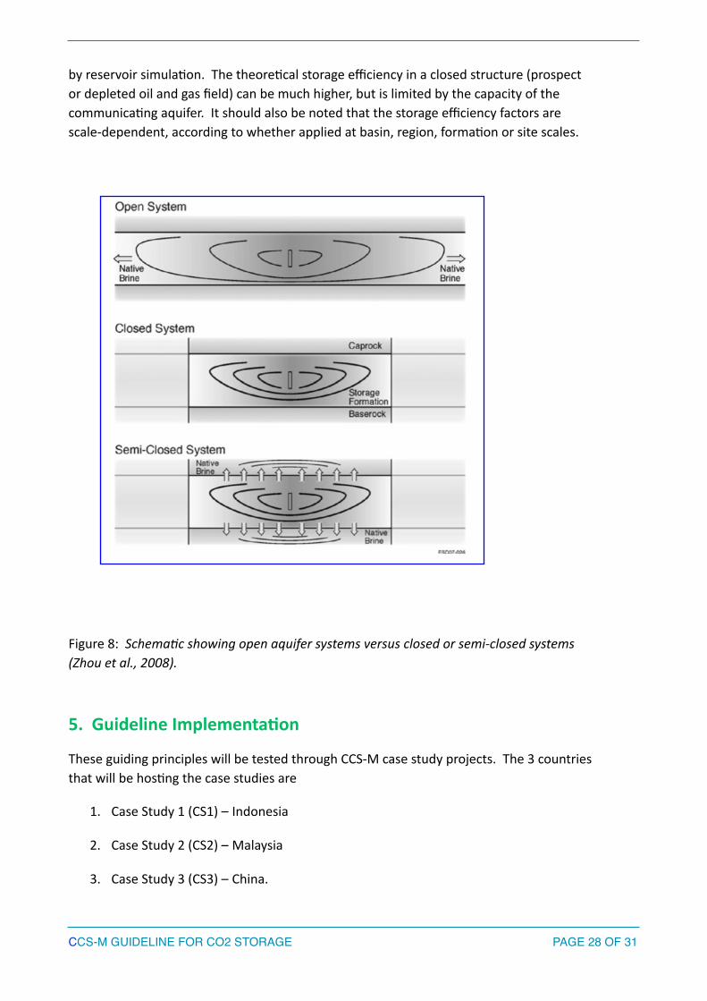
by reservoir simula<on. The theore<cal storage efficiency in a closed structure (prospect or depleted oil and gas field) can be much higher, but is limited by the capacity of the communica<ng aquifer. It should also be noted that the storage efficiency factors are scale-‐dependent, according to whether applied at basin, region, forma<on or site scales.
! !!!!!!!!!!!!!!!!!!!!!!!!!
Figure 8: Schema*c showing open aquifer systems versus closed or semi-‐closed systems (Zhou et al., 2008).
!5. Guideline ImplementaUon
These guiding principles will be tested through CCS-‐M case study projects. The 3 countries that will be hos<ng the case studies are
1. Case Study 1 (CS1) – Indonesia
2. Case Study 2 (CS2) – Malaysia
3. Case Study 3 (CS3) – China.
CCS-M GUIDELINE FOR CO2 STORAGE! ! PAGE � OF �28 31
The implementa<on of the case studies is through thema<c workshops and seminars. Best prac<ces, challenges and solu<ons will be recorded in the course of case study implementa<on and will be added in the Guideline. Geological fieldwork to outcrops or analogue storage reservoir will also be conducted during the case studies.
!6. Guideline EvaluaUon and Revision
The Guideline will go through a process of tes<ng/applica<on (via case studies and or storage projects), review and comments. The CCS-‐M website www.ccop.or.th/ccsm will also be used for review and comments from the member countries and also from resource persons.
The final version of the Guideline will also be refined in the future to evaluate whether or not it is necessary for further expansion or mapping to other methodologies (i.e. United Na<ons Framework Classifica<on for Fossil Energy and Mineral Reserves and Resources, UNFC 2009).
The CCS-‐M Guideline will reflect the CCOP Member Countries consensus on the methodologies to be adopted for the screening and characteriza<on of basins that could be used for the geological storage of CO2 , as well as for the quan<ta<ve es<ma<on of storage capaci<es.
The Guideline will be an important tool for communica<on and can provide a star<ng point for a specific storage project screening. This will be made available to all member countries; its usage, however is not mandatory.
!7. References !1. Asian Development Bank, Prospects for the Carbon Capture and Storage in Southeast
Asia, September 2013. 2. Bachu, S., Bonijoly, D., Bradshaw, J., Burruss, R., Holloway, S., Christensen, N.P., and
Mathiassen, O.M., 2007, CO2 storage capacity es<ma<on—Methodology and gaps: Interna<onal Journal of Greenhouse Gas Control, v. 1, p. 430–443.
3. Bachu, S. 2008 Comparison between Methodologies Recommended for Es<ma<on of CO2 Storage Capacity in Geological Media by the CSLF Task Force on CO2 Storage Capacity Es<ma<on and the US DOE Capacity and Fairways Subgroup of the Regional Carbon Sequestra<on Partnerships Program-‐ Phase III Report –Available online at hap://www.cslforum.org/publica*ons/documents/PhaseIIIReportStorageCapacityEs*ma*onTaskForce0408.pdf
4. Bradshaw, B.E., Spencer, L.K., Lah<nen, A.C., Khider, K., Ryan, D.J.,Colwell, J.B., Chirinos, A. and Bradshaw, J. (2009). Queensland Carbon Dioxide Geological Storage Atlas.
CCS-M GUIDELINE FOR CO2 STORAGE! ! PAGE � OF �29 31

5. Brennan, S.T., and Burruss, R.C., 2006, Specific storage volumes—A useful tool for CO2 storage capacity assessment: Natural Resources Research, v. 15, no. 3, p. 165–182, doi:10.1007/s11053–006–9019–0.
6. Brennan, S.T., Burruss, R.C., Merrill, M.D., Freeman, P.A., and Ruppert, L.F., 2010, A probabilis<c assessment methodology for the evalua<on of geologic carbon dioxide storage: U.S. Geological Survey Open-‐File Report 2010–1127, 31 p., available only at hMp://pubs.usgs.gov/of/2010/1127
7. Burruss, R.C., Brennan, S.T., Freeman, P.A., Merrill, M.D., Ruppert, L.F., Becker, M.F., Herkelrath, W.N., Kharaka, Y.K., Neuzil, C.E., Swanson, S.M., Cook, T.A., KleM, T.R., Nelson, P.H., and Schenk, C.J., 2009, Development of a probabilis<c assessment methodology for evalua<on of carbon dioxide storage: U.S. Geological Survey Open-‐File Report 2009–1035, 81 p., available only online at tp://pubs.usgs.gov/of/2009/1035/.
8. CO2CRC, 2013, Capturing Carbon Dioxide, available online at hMp://www.co2crc.com.au/dls/brochures/Capture_Brochure_2013_spread.pdf
9. CSLF June 2007 (hMp://www.cslforum.org/publica<ons/documents/PhaseIIReportStorageCapacityMeasurementTaskForce.pdf).
10. CCS-‐M Program, Member Country Presenta<ons, available online at hMp://ccop.or.th/ccsm/.
11. DNV, April 2012, Recommended Practice, DNV-RP-J203, Geological Storage of Carbon Dioxide, available online at http://www.dnv.com/news_events/news/2012/newcertificationframeworkforco2storage.asp
12. Global CCS Ins<tute, 2013, The Global Status of CCS 2013, available online at hMp://decarboni.se/sites/default/files/publica<ons/115203/Global-‐Status-‐CCS-‐2013-‐Summary.pdf.
13. Global CCS Ins<tute, 2014, The Global Status of CCS, February 2014 available online at hMp://decarboni.se/sites/default/files/publica<ons/121016/global-‐status-‐ccs-‐february-‐2014_0.pdf.
14. Gorecki,C.D. et al, Development of Storage Co-‐coefficients for Carbon Dioxide storage in Deep Saline Forma<ons and depleted Hydrocarbon Reservoirs, EERC Power Point presenta<on available online at :www.ifp.com/content/download/68004/1473899/file/32_Gorecki.pdf
15. Heidug, Wolf, Interna<onal Energy Agency, Workshop Report 2013, Methods to assess geologic CO2 storage capacity: status and best prac<ce (pdf).
16. R. M Prelicz, E.A.V. Mackie and C.J. OMo, Methodologies for CO2 storage es<ma<on: review and evalua<on of CO2 storage atlases, First Break, Volume 30, February 2012 available online at hMp://www.earthdoc.org/publica<on/publica<ondetails/?publica<on=56444
17. NACSA 2012 First Edi<on (hMp://www.netl.doe.gov/technologies/carbon_seq/refshelf/NACSA2012.pdf).
18. NETL, 2010, Carbon Sequestra<on Atlas of the United States and Canada III, available online at www.netl.doe.gov/technologies/ carbon seq/refshelf/atlasIII/ !
19. Norwegian Petroleum Directorate, Compiled CO2 Atlas for the Norwegian Con<nental Shelf, June 2014, available online at hMp://npd.no/en/Publica<ons/Reports/Compiled-‐CO2-‐atlas/
20. Norwegian Petroleum Directorate, CO2 Storage Atlas Barents Sea, December 2013, available online at hMp://npd.no/en/Publica<ons/Reports/CO2-‐storage-‐atlas-‐Barents-‐Sea/
CCS-M GUIDELINE FOR CO2 STORAGE! ! PAGE � OF �30 31
21. Norwegian Petroleum Directorate, CO2 Storage Atlas Norwegian Sea, January 2013, available online at hMp://npd.no/en/Publica<ons/Reports/CO2-‐storage-‐altas-‐Norwegian-‐Sea/
22. Norwegian Petroleum Directorate, CO2 Storage Atlas North Sea, December 2011, available online at hMp://npd.no/en/Publica<ons/Reports/CO2-‐Storage-‐Atlas-‐/
23. U.S. Department of Energy, Na<onal Energy Technology Laboratory, 2008a, Carbon sequestra<on atlas of the United States and Canada (2d ed.; Atlas II): 142 p., available online at hMp://www.netl.doe.gov/technologies/carbon_seq/refshelf/atlasII/2008%20ATLAS_Introduc<on.pdf.
24. Vercelli S. et al, 2014, Choosing good sites for storing CO2 underground, available online at http://www.sitechar-co2.eu/SciPublicationsData.aspx?IdPublication=339&IdType=557
CCS-M GUIDELINE FOR CO2 STORAGE! ! PAGE � OF �31 31