c/cs 409 - irp-cdn.multiscreensite.com · 12/31/2016 · the standard version c 409.2 is designed...
TRANSCRIPT

( ) *
( ) *( ) *
*
( ) *( ) *( ) *( ) *
* available until 31.12.2016

2 www.sera-web.com Subject to technical modifications! TA 414 Rev. 11 en 06/2016
Controllable diaphragm pump
C/CS 409.2Operating instructions

3TA 414 Rev. 11 en 06/2016 Subject to technical modifications! www.sera-web.com
Controllable diaphragm pump
C/CS 409.2Operating instructions
Table of contents
Q. Quickstart ..................................................................................................................................................6Q.1 Power connection ................................................................................................................................6Q.2 Control elements .................................................................................................................................7Q.3 LED operation indicators .....................................................................................................................7Q.4 Key operation ......................................................................................................................................8Q.5 Factory settings ...................................................................................................................................8Q.6 Control inputs and outputs ...................................................................................................................9
Q.6.1 Control via contact signal ............................................................................................................9Q.6.2 Control via analog signal .............................................................................................................9
Q.7 Selecting the operating mode ............................................................................................................101. General ..................................................................................................................................................... 11
1.1 General user information .................................................................................................................... 111.2 Symbols and notes used in these operating instructions ................................................................... 111.3 Notes attached to the product ............................................................................................................ 111.4 Quality instructions .............................................................................................................................12
2. Safety instructions ..................................................................................................................................122.1 Personnel qualification and training ...................................................................................................122.2 Dangers in case of inobservance of the safety instructions ...............................................................122.3 Safety conscious working ...................................................................................................................122.4 Safety instructions for owner / operator ..............................................................................................132.5 Safety instructions for maintenance, servicing and installation work .................................................132.6 Arbitrary modification and production of spare parts ..........................................................................132.7 Improper operations ...........................................................................................................................132.8 Intended use .......................................................................................................................................132.9 Operating conditions ..........................................................................................................................142.10 Personal protection for maintenance and service ............................................................................142.11 Utilities/Lubricants ............................................................................................................................142.11 Foreseeable misuse .........................................................................................................................15
2.11.1 Transport ..................................................................................................................................152.11.2 Assembly and installation .........................................................................................................152.11.3 Start-up .....................................................................................................................................152.11.4 Operation ..................................................................................................................................162.11.5 Maintenance / Repair ...............................................................................................................162.11.6 Cleaning ...................................................................................................................................162.12.7 Shut-down ................................................................................................................................172.12.8 Disassembly .............................................................................................................................172.12.9 Disposal ...................................................................................................................................17
3. Transport and storage ............................................................................................................................183.1 General ...............................................................................................................................................183.2 Storage ...............................................................................................................................................18
4. Product description ................................................................................................................................194.1 Types ..................................................................................................................................................19
4.1.1 Type key .....................................................................................................................................194.1.2 Type plate ...................................................................................................................................20
4.2 Materials .............................................................................................................................................204.3 Viscosity, pumped medium .................................................................................................................204.4 Dosing range ......................................................................................................................................204.5 Noise measurement ...........................................................................................................................204.6 Components of the diaphragm pump .................................................................................................21
4.6.1 C409.2 ........................................................................................................................................214.6.2 CS409.2 .....................................................................................................................................22
4.7 Functional description ........................................................................................................................234.7.1 General ......................................................................................................................................234.7.2 Stroke length adjustment ...........................................................................................................234.7.3 Drive motor .................................................................................................................................234.7.4 Stroke length adjustment ...........................................................................................................244.7.5 Assembly pump ..........................................................................................................................27

4 www.sera-web.com Subject to technical modifications! TA 414 Rev. 11 en 06/2016
Controllable diaphragm pump
C/CS 409.2Operating instructions
4.7.6 Pump body .................................................................................................................................274.7.7 Pump body with integrated overflow valve .................................................................................274.7.8 Suction / Pressure valve ............................................................................................................284.7.9 Electronics (operating panel) .....................................................................................................284.7.10 Diaphragm rupture monitoring device (option) .........................................................................294.7.11 Manual vent valve (only FRP-execution C 409.2-0,8e - …-2,4e) .............................................294.7.12 Automatic ventilation device (CS-design) .................................................................................30
5. Technical data ..........................................................................................................................................315.1 Performance data ...............................................................................................................................315.2 Motor data ..........................................................................................................................................325.3 Additional data for electronics ............................................................................................................325.4 Dimensions .........................................................................................................................................33
5.4.1 C 409.2 .......................................................................................................................................335.4.2 CS 409.2 ....................................................................................................................................38
6. Assembly / Installation ............................................................................................................................416.1 Provide overpressure protection ........................................................................................................436.2 Prevent a backflow of the pumped medium .......................................................................................446.3 Eliminate undesired siphoning ...........................................................................................................456.4 How to ensure an gas-free suction .....................................................................................................456.5 Install the empty-tank alarm ...............................................................................................................466.6 How to avoid an emptying of the suction line .....................................................................................466.7 Line strainer ........................................................................................................................................476.8 Suction via a siphon pipe ...................................................................................................................476.9 In case of slightly degassing dosing media ........................................................................................486.10 Dosing of suspensions .....................................................................................................................486.11 Damping of the pulsation ..................................................................................................................49
7. Electrical connections ............................................................................................................................517.1 Electric supply ....................................................................................................................................517.2 Electrical interfaces ............................................................................................................................52
7.2.1 Control inputs and outputs .........................................................................................................527.2.2 Level input with pre-alarm and dry run .......................................................................................547.2.3 Input for flow control and flow meter ..........................................................................................55
8. Operation in non-hazardous areas ........................................................................................................559. Start-Up ....................................................................................................................................................56
9.1 Driving Motor ......................................................................................................................................569.2 Initial start / Restart ............................................................................................................................56
10. Operation ...............................................................................................................................................5710.1 Operating elements ..........................................................................................................................5710.2 LED operation indicators ..................................................................................................................5710.3 Key operation ...................................................................................................................................5810.4 Parameter table ................................................................................................................................5910.5 Menu ................................................................................................................................................61
10.5.1 Screen “Operating messages” .................................................................................................6110.5.2 Fault and warning messages ...................................................................................................6210.5.3 Screen “Main menu” .................................................................................................................6310.5.4 Value entry ...............................................................................................................................6310.5.5 Menu guide ..............................................................................................................................65
10.6 Selecting the operation mode ...........................................................................................................7010.7 Additional settings for the operation mode .......................................................................................71
10.7.1 Additional settings for the ANALOG operation mode ...............................................................7110.7.2 Additional settings for the PULSE mode ..................................................................................7510.7.3 Additional settings for the BATCH mode ..................................................................................7610.7.4 Settings for the EXTERNAL operation mode ...........................................................................78
10.8 Configuring the inputs and outputs ...................................................................................................7810.8.1 Digital input 01 .........................................................................................................................7910.8.2 Digital/analog inputs 02 and 03 ................................................................................................8010.8.3 Outputs 01 and 02 ....................................................................................................................80
10.9 Flow rate indicator ............................................................................................................................8110.10 Calibration ......................................................................................................................................83

5TA 414 Rev. 11 en 06/2016 Subject to technical modifications! www.sera-web.com
Controllable diaphragm pump
C/CS 409.2Operating instructions
10.11 System ............................................................................................................................................8510.12 Totalizer ..........................................................................................................................................8510.13 Password ........................................................................................................................................8510.14 Info .................................................................................................................................................8710.15 Extras .............................................................................................................................................87
10.15.1 Slow-Mode .............................................................................................................................8710.15.2 Dosing monitoring ..................................................................................................................8710.15.3 Diaphragm rupture detection (OPTION) ................................................................................8810.15.4 Level monitoring .....................................................................................................................8910.15.5 Venting automatic (only with CS 409.2) .................................................................................90
11. Maintenance ...........................................................................................................................................9211.1 Working materials .............................................................................................................................9311.2 Drive unit ..........................................................................................................................................94
11.2.1 Drive motor ...............................................................................................................................9411.2.2 Oil change ................................................................................................................................94
11.3 Dosing unit ........................................................................................................................................9511.3.1 Overview of the tightening torques ...........................................................................................9511.3.2 Changing the Diaphragm..........................................................................................................96
12. Spare and wearing parts .....................................................................................................................10012.1 Wearing parts .................................................................................................................................10012.2 Spare parts .....................................................................................................................................10012.3 Spare and wearing parts ................................................................................................................101
12.3.1 Diaphragm pump C 409.2- 0,8 e ...-2,4 e ..............................................................................10112.3.2 Diaphragm pump C 409.2- 4,0 (e) ...-180 (e) ........................................................................10212.3.3 Diaphragm pump C 409.2-250 (e) ...-350 (e) ......................................................................10412.3.4 Diaphragm pump C 409.2- 4,0 (e) ...-180 (e)
with integrated overflow valve .................................................................................................10612.3.5 Diaphragm pump C 409.2-250 (e) ...-350 (e)
with integrated overflow valve .................................................................................................10812.3.6 Diaphragm pump CS 409.2- 0,8 e ...-2,4 e ........................................................................... 11012.3.7 Diaphragm pump CS 409.2- 4,0 (e) ...-25 (e) ....................................................................... 11212.3.8 Diaphragm pump CS 409.2- 4,0 (e) ...-25 (e)
with integrated overflow valve ................................................................................................. 11413. Fault analysis and corrective action ................................................................................................. 116
13.1 Analysis of the plain text error messages ....................................................................................... 11613.2 Analysis of other faults ................................................................................................................... 118
14. Shut-down ............................................................................................................................................12015. Disposal ...............................................................................................................................................120
15.1 Dismantling and transport ..............................................................................................................12015.2 Complete disposal ..........................................................................................................................120
16. Clearance Certificate ...........................................................................................................................121

6 www.sera-web.com Subject to technical modifications! TA 414 Rev. 11 en 06/2016
Controllable diaphragm pump
C/CS 409.2Operating instructions
Q. Quickstart“Quickstart” is used to start-up the pump quickly without having read the operating instructions in detail.
The Quickstart does not claim to be complete and does not relieve the user from reading the complete instruc-tions!
INFO!
Q.1 Power connectionThe sera diaphragm pump is delivered ready for installation. Standard delivery includes a 2m power cable with Euro plug. The standard version C 409.2 is designed for an operating voltage range of 210 – 250 V, 50/60 Hz.
The self-venting version CS 409.2 has a limited operating voltage range. The specifications on the type plate must absolutely be adhered to!
The CS 409.2 is available in three versions:
210 – 250 V, 50/60 Hz 100 – 120 V, 50 Hz 100 – 120 V, 60 Hz
ATTENTION!
The pump restarts in the selected operating mode after the power supply was switched on or a power supply recovery following a mains failure!
ATTENTION!
Symbol:
Only operate the pump when it is connected to an earthed power supply!
ATTENTION!

7TA 414 Rev. 11 en 06/2016 Subject to technical modifications! www.sera-web.com
Controllable diaphragm pump
C/CS 409.2Operating instructions
3
4
5
61
2
1 STOP/START key
2 LED operation indications
3 LCD-display
4 UP key
5 DOWN key
6 ENTER key
Q.3 LED operation indicators
Three light-emitting diodes (LED) indicate the status of the pump:
Green: Operation and stroke indicatorWhen switching on the pump, the green LED lights steadily. The operation indicator works in combina-tion with a stroke indicator; during pump operation, the LED flashes in accordance with the current stroke frequency.
Yellow: Warning indicatorThe yellow LED indicates all occurring warning messages (cp. table "Overview LED Operation Indicator" in chapter “LED Operation Indicator"). The warning is not only indicated by the LED but also as plain text in the LCD display.
Red: Fault indicatorThe red LED indicates all occurring faults (cp. table "Overview LED Operation Indicator" in chapter “LED Operation Indicator"). The fault is not only indicated by the LED but also as plain text in the LCD display.
Q.2 Control elements

8 www.sera-web.com Subject to technical modifications! TA 414 Rev. 11 en 06/2016
Controllable diaphragm pump
C/CS 409.2Operating instructions
Q.4 Key operation
Operation of the pump is performed with 4 keys:
STOP/START key
START
STOP
ENTER
After connection to the power supply, the pump is switched ON/OFF using the STOP/START key.
ENTER key
START
STOP
ENTER
You can use the ENTER key to open and confirm value input fields and to select menu items.
UP- / DOWN key
START
STOP
ENTER
Using the UP/DOWN key, you can scroll the different menu items / menu levels and select the display of various operating messages.During parameter adjustment, the UP key is used to increase the parameter value and the DOWN key is used to decrease the parameter value.
Q.5 Factory settingsThe factory setting of the pump electronics is specified in Chapter “Parameter table”.

9TA 414 Rev. 11 en 06/2016 Subject to technical modifications! www.sera-web.com
Controllable diaphragm pump
C/CS 409.2Operating instructions
Q.6 Control inputs and outputs
Q.6.1 Control via contact signal
Figure: "Control of digital inputs via a potential-free contact signal and control of a relay via an output of the dosing pump”
Q.6.2 Control via analog signal
Figure: "Control of analog/digital inputs via an analog signal, potential-free contact signal and control of a relay via an output of the dosing pump”
Collecting Fault (15V DC)
Extern Stop
Contact signal
Contact signal
Pulse
-
+
RD + BU
PK
GY
YE
GN
BN
WH
Output 01 Collecting fault max. 50 mA
Extern Stop
+4 ... 20mAAnalog 01
-
+
RD + BU
PK
GY
YE
GN
BN
WH
0V (Ground) / -4...20mA
Control cabinet customer

10 www.sera-web.com Subject to technical modifications! TA 414 Rev. 11 en 06/2016
Controllable diaphragm pump
C/CS 409.2Operating instructions
Operation Menu e.g. current stroke frequency (depending on chosen operation mode)
START
STOP
ENTER
+
START
STOP
ENTER
PW01
Main Menu
Operation Mode
START
STOP
ENTER
>Operation Mode<
START
STOP
ENTER
ManualPulseAnalogBatchExtern
START
STOP
ENTER
START
STOP
ENTER
START
STOP
ENTER
PW02
Q.7 Selecting the operating modeProceed as follows to select the operating mode:
Input the password PW01 (factory setting 9990) to release the programming levels. Change the operating mode.
PW01 Locking by password 01 (pre setting ex work: 9990, not activated)
PW02 Locking by password 02 (pre setting ex work: 9021)

11TA 414 Rev. 11 en 06/2016 Subject to technical modifications! www.sera-web.com
Controllable diaphragm pump
C/CS 409.2Operating instructions
Before commissioning and during operation of the sera dosing pump the respective regulations valid at the place of installation are to be observed.The sera dosing pump is delivered ready for installation. Carefully read these instructions and especially the safety instructions herein contained before installation and initial start-up of the pump.
1. General
Special notes in these operating instructions are marked with text and danger symbols.
Designation of the note Danger type Definition of the note
(Text and symbol)
Dan
ger o
f fat
al in
jury
Ris
k of
inju
ry
Dam
age
to p
rope
rty
(in the operating instructions)
DANGER! X X XIdentifies an imminent danger that results in fatal or severe injuries if not avoided.
WARNING! X X XDesignates a potentially dangerous situation There might be danger to life or serious injury and damage to property if it is not avoided.
CAUTION! X XDesignates a potentially dangerous situation There might be slight or minor injury or damage to property if it is not avoided.
ATTENTION! XDesignates a potentially dangerous situation that could lead to damage to property if not avoided.
NOTE! Designates information which helps to make work easier and is useful for trouble-free operation.
1.3 Notes attached to the productSymbols which are directly attached to the pump, e.g. arrows for direction of rotation or symbols for fluid connections are to be observed and kept in legible condition.
1.2 Symbols and notes used in these operating instructions
1.1 General user information

12 www.sera-web.com Subject to technical modifications! TA 414 Rev. 11 en 06/2016
Controllable diaphragm pump
C/CS 409.2Operating instructions
1.4 Quality instructionsObservance of these operating instructions and, in particular, the safety instructions, helps to
avoid dangers to persons, machines and environment. increase reliability and service life of the product and the complete system. reduce repair cost and downtime.
The sera quality management and quality assurance system for pumps, systems, valves and fittings and compres-sors is certified according to ISO 9001:2008.The sera product meets the valid safety and accident prevention regulations.
Always keep these operating instructions within reach at the place of installation.
ATTENTION!
Pay attention to the safety data sheet of the medium! The owner must take cor-responding accident prevention measures to protect operating personnel from danger through the delivery media used!
WARNING!
The personnel for operation, maintenance, inspection and installation must be suitably qualified for their tasks. The owner must clearly define responsibility and supervision of the personnel. If the personnel do not have the knowledge required, then personnel is to be trained and instructed correspondingly. Such training can be provided by the manufacturer / supplier upon order of the owner. In addition, the owner has to ensure that personnel have understood the operating instructions completely.
Inobservance of these safety instructions can result in danger to persons, hazards to the environment and damage to the product.Inobservance of the safety instructions may lead to:
Failure of important functions of the product/system. Inobservance of prescribed methods for maintenance and servicing. Danger to persons through electrical, mechanical and chemical influences. Hazards to the environment through leaking dangerous media.
The safety instructions specified in this operating manual, the national regulations for accident prevention, the safety regulations for the pumped medium valid at the place of installation as well as internal working-, operating-, and safety instructions of the owner are to be observed.
2.3 Safety conscious working
2.2 Dangers in case of inobservance of the safety instructions
2.1 Personnel qualification and training
2. Safety instructions

13TA 414 Rev. 11 en 06/2016 Subject to technical modifications! www.sera-web.com
Controllable diaphragm pump
C/CS 409.2Operating instructions
The owner must ensure that any maintenance-, servicing- and installation work is only entrusted to authorized andsuitably qualified personnel who have carefully read and understood the operating instructions.
Only those spare parts and operating supplies are to be used which meet the requirements of the specified opera-ting conditions.
Threaded joints and connections may only be disconnected when the system is not under pressure.
Modifications of or changements to the pump are only permitted after previous agreement of the manufacturer. Origi-nal spare parts and accessories which were approved by the manufacturer are essential for safety reasons.
If the pumps (e.g. drive motor) are modified without au-thorization of the manufac-turer or spare parts are used which are not approved, any warranty claim becomes null and void.
CAUTION!
The sera product is only to be deployed according to the intended purpose stated in the product description and the acceptance test certificate.If the product is to be used for other applications, then the suitability of the product for the new operating conditions must be discussed with sera beforehand!Criteria for operation in accordance with the intended use:
Observe characteristics of the medium (please see safety- and product data sheet of the delivery medium – the safety data sheet is to be provided by the supplier / owner of the medium).
Resistance of the materials which come into contact with the medium. Operating conditions at the place of installation. Pressure and temperature of the medium. Voltage supply.
Operating safety of the supplied product is only guaranteed if the product is used as intended, according to the descriptions in Chapter 2.8 of these operating instructions.
2.4 Safety instructions for owner / operatorLeaking hazardous delivery media and operating supplies are to be disposed off in such a way that any danger to persons and the environment is excluded. The legal regulations are to be observed.
Danger caused by electrical energy is to be avoided.
2.8 Intended use
2.7 Improper operations
2.6 Arbitrary modification and production of spare parts
2.5 Safety instructions for maintenance, servicing and installation work

14 www.sera-web.com Subject to technical modifications! TA 414 Rev. 11 en 06/2016
Controllable diaphragm pump
C/CS 409.2Operating instructions
2.10 Personal protection for maintenance and serviceThe provisions of the German Ordinance on Hazardous Substances (GefStoffV) (§14 Safety Data Shee) and relevant national safety regulations for the pumped medium must strictly be adhered to.
In case of accidents check whether the following substances are emitted:
Leaking fluids. Leaking vapours. Noise emissions (sound level).
Emissions are to be monitored by corresponding controly systems of the total installation.
Wear protective clothing, gloves, breathing mask and a face protecting mask.
ATTENTION!
Personal protective equipment must be provided by the owner!
NOTE!
NOTE!
If not agreed otherwise in the contract conditions, the sera dosing pump will always be supplied with the necessary utilities. (For type and quantitiy of utilities/lubricants, see Chapter 11.1 „Working materials“).
2.9 Operating conditions Ambient temperature: 0°C to 40°C Climate: relative air humidity < 90% Installation altitude: max 1000m above sea level Pump design data for dosing and its temperature can be found in the order confirmation.
2.11 Utilities/Lubricants

15TA 414 Rev. 11 en 06/2016 Subject to technical modifications! www.sera-web.com
Controllable diaphragm pump
C/CS 409.2Operating instructions
2.11 Foreseeable misuse
Power supply not fuse protected (no fuse/fuse too large, power supply not conforming to standards). No or improper fastening material of the pump. Improper connection of the pressure pipes, wrong material i.e. PTFE tape and unsuitable connection pieces. Liquid pipes confused. Threads overturned/damaged. Pipes bent during connection in order to compensate for alignment errors. Supply voltage connected without earthed conductor. Socket for safe disconnection of the power supply difficult to reach. Wrong connecting cables for supply voltage (cross-section too small, wrong insulation). Parts damaged (e.g. vent valve, flow meter broken off). Wrongly dimensioned pressure and suction pipe. Incorrect dimensioned and improperly fastened pump panel (panel broken off). The pumped medium is conveyed into the environment in the case of pumps with automatic or manual vent
valve if the return pipe was improperly fitted or not fitted at all. Danger for the operator.
Cover on vent openings (e.g. motor). Suction or pressure pipes closed (i.e. foreign matters, particle size, stop valves). Start-up with damaged system. Integrated overflow valve misadjusted (no protection function). Operation without connected return pipe of the integrated overflow valve. No free return flow of the overflow valve. Operation without connected return pipe of the vent valve.
Mains plug cut off (direct connection), safe disconnection impossible. Safe disconnection e.g. by 2-pin main switch.
Short circuit of the internal power supply (15V DC) at the control cable during installation. Admissible current load of the digital outputs exceeded No sera sensors for flow or filling level damage to the electronics. No diode for external control power supply connection electronics overloaded/destroyed. Electronics opened in order to connect the mains cable directly to the power supply electric shock or
damage to the electronics. Connection of wrong supply voltage or mains frequency electronics or vent valve destroyed.
Sensor cable damaged (electronics <--> stroke mechanism), wrong or no recognition of the stroke length wrong dosing volume and resulting process error.
Wrong parameterization of the pump inadvertent start. Distance between dosing pump and other dosing pumps or electrical consumers insufficient fault by elec-
tromagnetic radiation..
The following misuse is assigned to the life cycles of the machine.
Misuse can result in danger to the operating personnel!
DANGER!
Tipping behavior during transport, loading and unloading ignored. Weight for lifting underestimated.
2.11.2 Assembly and installation
2.11.1 Transport
2.11.3 Start-up

16 www.sera-web.com Subject to technical modifications! TA 414 Rev. 11 en 06/2016
Controllable diaphragm pump
C/CS 409.2Operating instructions
2.11.6 Cleaning
2.11.4 Operation
2.11.5 Maintenance / Repair
Control cables too long >> 30m malfunctions due to EMC. Control cable and power cable laid in parallel malfunctions due to EMC.
If the screw-in depth of the setscrew for the integrated overflow valve is not noted, this may lead to dan-gerous consequences, i.e. rupture of the pressure pipe or leaking medium. …).
Works carried out which are not described in the operating instructions (works on the stroke mechanism and the assembly pump, electronics opened).
Prescribed maintenance schedules ignored. Use of wrong spare parts/oils (e.g. no sera original spare parts, wrong viscosity). Improper mounting of spare and wearing parts (e.g. wrong tightening torque for pump body). Oil level not checked. Use of cables with damaged insulation. No shut down / no protection against a restart before maintenance work. Pumped medium or utilities during an oil change insufficiently removed. Restart without sufficient fastening. Valves confused. Sensor pipes confused. Pipes not connected (e.g. suction- and pressure pipes, gas pipes). Gaskets damaged, medium is leaking. Gaskets not fitted, medium is leaking. Wearing of unsuitable protective clothing / no protective clothing at all. Operation of an uncleaned system. Pumped medium contaminated with oil. Poorly ventilated room.
Integrated overflow valve misadjusted. No free return flow of the integrated overflow valve.
Fault message ignored faulty dosing / process error. Pipes hit, pulsation damper not used damage to the pipes, medium is leaking. Pumped medium contains particles or is contaminated. External fuse bridged no cut off in case of an error. Ground wire removed no cut off by fuse in case of an error, supply voltage directly at the housing. Insufficient lighting of the working place. Suction height too high, pump capacity too low process error. Arbitrary modification of the pump (valves, internal fuse, …).
No supervision of leakages MBE opening. Diaphragm rupture is not indicated when the MBE plug was disconnected. Medium can escape into the envi-
ronment through the vent hole “Danger to the operator and the environment”.
Wrong rinsing medium (material changed, reaction with the medium). Wrong cleaning agent (material changed, reaction with the medium). Cleaning agent remains in the system (material changed, reaction with the medium). Protective clothing insufficient or missing. Use of unsuitable cleaning utensils (material changed, mechanical damage by high pressure cleaner). Untrained personnel. Vent openings clogged. Parts torn off. Sensors damaged.

17TA 414 Rev. 11 en 06/2016 Subject to technical modifications! www.sera-web.com
Controllable diaphragm pump
C/CS 409.2Operating instructions
Non-observance of the safety data sheet. Control elements actuated. Poorly ventilated room.
Pumped medium not completely removed. Disassembly of pipes with the pump running/with residual pressure. Disconnection of the electrical connections in a wrong sequence (ground wire first). Disconnection from the power supply not ensured danger through electricity. Poorly ventilated room.
2.12.7 Shut-down
Residues of the pumped medium and utilities in the system. Use of wrong disassembly tools. Wrong or no protective clothing at all. Poorly ventilated room.
2.12.8 Disassembly
Improper disposal of the pumped medium, utilities and materials. No marking of hazardous media.
2.12.9 Disposal
Wrong disposal of the elctronics.

18 www.sera-web.com Subject to technical modifications! TA 414 Rev. 11 en 06/2016
Controllable diaphragm pump
C/CS 409.2Operating instructions
3. Transport and storage
3.1 General
3.2 Storage
sera products are checked for perfect condition and function previous to shipment.Check for transport damage immediately after arrival of goods. If damage is found, this is to be reported immediately to the responsible carrier and the manufacturer.
The packaging material must be disposed of appropriately!
NOTE!
An undamaged packaging protects the unit during storage and should only be opened when the product is installed.
Proper storage increases the service life of the product and includes prevention of negative influences such as heat, moisture, dust, chemicals etc.
The following storage specifications are to be obsered:
Storage place: cool, dry, dustfree and slightly ventilated Storage temperature between +2°C and +40°C Relative air humidity not more than 50 %. The maximum storage time for the standard system is 12 months.
If these values are exceeded, metal products should be sealed in foil and protected from condensation water with a suitable desiccant.
Do not store solvents, fuels, lubricants, chemicals, acids, disinfectants and similar in the storage room.

19TA 414 Rev. 11 en 06/2016 Subject to technical modifications! www.sera-web.com
Controllable diaphragm pump
C/CS 409.2Operating instructions
4. Product description
Type of drive (combinations possible)
C controllableS self ventilatingM not adjustableR generally adjustableF Motor suitable for frequency converter operationi Frequency converter, mounted on the motorP Pole-changing motorK Stroke mechanism with side drive shaft and connected to the drive via a clutchZ twin designX Stroke mechanism with two opposite pump heads, combined suction and pressure sideY Stroke mechanism with two opposite pump heads
Series204 (solenoid driven pumps)409 (motor driven pumps)410 (motor driven pumps)411 (motor driven pumps)509 (motor driven pumps)510 (motor driven pumps)511 (motor driven pumps)
Revision index
max. Nominal capacity (litre/hour (each pump head))
Displacer (type of construction)
(without) Double diaphragme Single diap hragmML Multy-layer diaphragm
1 2 3 4 5
KM Piston DiaphragmK Piston
C 409 . 2 - 50 e (example)
4.1.1 Type key
4.1 Types

20 www.sera-web.com Subject to technical modifications! TA 414 Rev. 11 en 06/2016
Controllable diaphragm pump
C/CS 409.2Operating instructions
4.1.2 Type plateEach sera dosing pump is factory provided with a type plate. The following information can be found on this type plate.
4.2 MaterialsThe materials used are stated in the order confirmation and the product description.
4.3 Viscosity, pumped mediumThe diaphragm pump is suitable for fluids with viscosities < 100 mPas.
4.4 Dosing rangeThe delivery rate of the diaphragm pump can be set manually via the stroke length adjustment (0…100%).The linear dosing range is between 20% and 100%.
4.5 Noise measurementAccording to DIN 45635 the sound pressure level measured of the diaphragm pumps is between 50 and 65 dB (A).
Type
No.
P1 min/max
P2 max
bar
bar
nN
Hydrfl
QN l/h
1/min
cm3
1
2
3
4 5
7
6
No. Designation
1 Pump type
2 Serial number of the pump
3Minimum/maximum permissible pressure in the pump inletMinimum/maximum permissible pressure in the inlet cross section which the pump can be used for. Please consider that pressure depends on rotation speed, delivery rate, temperature and static pressure at the inlet.
4Maximum permissible pressure in the pump outletMaximum permissible pressure in the outlet cross section which the pump can be used for. Please consi-der that pressure depends on rotation speed, delivery rate, temperature and static pressure at the outlet.
5 Buffer fluidQuantity of buffer fluid in the diaphragm ring (in the case of double diaphragm pumps).
6 Nominal stroke frequency
7Nominal delivery rateDelivery rate which the pump was ordered for, based on the nominal rotation speed nN, the nominal deli-very height p2max. and the delivery medium stated in the supply contract.

21TA 414 Rev. 11 en 06/2016 Subject to technical modifications! www.sera-web.com
Controllable diaphragm pump
C/CS 409.2Operating instructions
4.6 Components of the diaphragm pump
No. Designation Remark1 Electronics2 Driving motor3 Manual stroke length adjustment4 Manual stroke length adjustment with position indicator option5 Stroke length adjustment with actuator option6 Stroke mechanism7 Suction valve8 Assembly pump (double diaphragm design)9 Diaphragm rupture electrode MBE-03 (for double diaphragm pumps) option10 Diaphragm rupture electrode MBE-02 (for single diaphragm pumps) option11 Assembly pump (single diaphragm design)12 Pump body13 Pump body with integrated overflow valve14 Pressure valve
4.6.1 C409.2
1 2 3
4
5
7
9
8
6
11
12
13
14
10

22 www.sera-web.com Subject to technical modifications! TA 414 Rev. 11 en 06/2016
Controllable diaphragm pump
C/CS 409.2Operating instructions
No. Designation Remark1 Electronics2 Driving motor3 Manual stroke length adjustment4 Manual stroke length adjustment with position indicator option5 Stroke length adjustment with actuator option6 Stroke mechanism7 Suction valve8 Assembly pump (double diaphragm design)9 Diaphragm rupture electrode MBE-03 (for double diaphragm pumps) option10 Diaphragm rupture electrode MBE-02 (for single diaphragm pumps) option11 Assembly pump (single diaphragm design)12 Pump body13 Pump body with integrated overflow valve14 Pressure valve15 Vent valve
4.6.2 CS409.2
1 2 3
4
5
7
98
6
11
12
13
14
10
15

23TA 414 Rev. 11 en 06/2016 Subject to technical modifications! www.sera-web.com
Controllable diaphragm pump
C/CS 409.2Operating instructions
4.7 Functional description
3
1
2
4.7.3 Drive motor
4.7.3.1 Motor protection
sera dosing pumps are run-dry safe oscillating displacement pumps that are characterised by high tightness of the dosing head. The fluid is conveyed by a deformable diaphragm.
Piston diaphragm pumps of this type series use a rotary cam drive to transmit the rotation of the drive motor to the displace-ment body.In case of the rotary cam drive, the eccentric (2) provides the pressure stroke while the suction stroke is performed by a pres-sure spring (return spring) (3).The effective stroke length can be changed by means of an adjustable scale knob (1) which prevents the connecting rod from following the rotary cam up to the rear dead centre during suction stroke (see stroke length adjustment).
Controllable diaphragm pumps consist of the following (main) components:
Stroke mechanism Drive motor Electronics Stroke length adjustment Assembly pump Pump body Suction and pressure valve Automatic ventilation device (CS-design)
A sera diaphragm pump of series C/CS 409.2 is driven by a threephase-motor controlled by the electronics.
A protective motor switch is not necessary due to the fact that a thermic overload protection is integrated in the pump for the protection of the motor.
4.7.2 Stroke length adjustment
4.7.1 General

24 www.sera-web.com Subject to technical modifications! TA 414 Rev. 11 en 06/2016
Controllable diaphragm pump
C/CS 409.2Operating instructions
4.7.4 Stroke length adjustment
4.7.4.1 Manual stroke length adjustment (standard)
+ l/h- l/h
The effective stroke length of the connecting rod is changed by turning the scale knob.The stroke length should be adjusted during operation of the pump.The set stroke length can be read off a scale, e.g. 75% (see Fig.).With the 20-steps adjustment on the scale knob, the stroke length can be set individually with a tolerance of 0.5%.
A protecting cap can be provided for the protection of the stroke length adjustment against unintentional adjustment.
Protection for stroke length adjustment (option)
The delivery rate of the pump is set by changing the stroke length. The stroke length is infinitely variable between 0% and 100%.
A linear dosing behaviour is achieved with stroke length adjustments between 20% and 100%.

25TA 414 Rev. 11 en 06/2016 Subject to technical modifications! www.sera-web.com
Controllable diaphragm pump
C/CS 409.2Operating instructions
4.7.4.2 Manual stroke length adjustment by a dial scale with indication of percent (option)
The stroke length is adjusted by turning the hand wheel. The stroke length shuold be adjusted during operation of the pump.
The set stroke length can be read off the percent scale (the example shows a set stroke length of 65%).In delivery state, the stroke length adjustment is factory set to 50%.
+ l/h- l/h
The dial scale with indication of percent may become misadjusted during transport.If the indicator does not match the 50% setting, then the percent scale must be re-adjusted during operation (!) of the pump!
ATTENTION!
Adjusting the percent scale:
Switch on the piston diaphragm pump. Loosen setscrew (1). Remove percent scale (2) from the hand wheel (3). Manually turn the percent scale to 0% setting. Use the hand wheel to set the stroke length to 0%.
Turn hand wheel clockwise until there is no further stro-ke movement (connecting rod does no longer hit the adjusting spindle (4)).
Insert percent scale again. Use the setscrew to secure the percent scale to the
hand wheel. Adjust desired stroke length.
3
2
4
1

26 www.sera-web.com Subject to technical modifications! TA 414 Rev. 11 en 06/2016
Controllable diaphragm pump
C/CS 409.2Operating instructions
4.7.4.4 Automatic stroke length adjustment by means of an electrical actuator with integrated positioner (PMR3)
same as Chapter 4.7.4.3, additionally:
PMR3 positioner
This PMR3 positioner which is integrated in the actuator enables an actuator setting from 0…100% that is proportional to the connected input signal.As an option, the actuator can also be provided with a collective interference signal.Information on the electrical connection is given inside the cover of the actuator.
4.7.4.3 Automatic stroke length adjustment by means of an electrical actuator
The electrical actuator is directly mounted to the stroke me-chanism (1) of the dosing pump. A clutch transmits the rota-ry motion of the actuator drive shaft to the adjusting spindle. The axial displacement is compensated in the clutch (2).In case of dosing pumps with electrical actuator, a manual adjustment of the stroke length on the pump is no longer possible.(Exception: actuator with hand wheel)The actuator is equipped with two integrated limit switches as well as a position potentiometer for position feedback as standard.Both limit switches are factory set so that the drive will switch off at a stroke length of 0% and 100%, even if a con-trol voltage is applied.This guarantees that adjustments can only be made within the permissible range. The position potentiometer is driven by a safety clutch which prevents damage caused by incor-rectly adjusted limit switches.Activation is performed by appropriate control units(see sera - accessories)
21
The set stroke length can be read off on the pump (percent scale)Information on the electrical connection is given inside the cover of the actuator.
The adjustment is only possible when the pump is running.
ATTENTION!

27TA 414 Rev. 11 en 06/2016 Subject to technical modifications! www.sera-web.com
Controllable diaphragm pump
C/CS 409.2Operating instructions
There are two different pump types:
Single diaphragm pump (A) Double diaphragm pump (B)
Single diaphragm pump (A)
The drive diaphragm (2) connected to the drive via the con-necting rod (1) transmits the stroke movement directly to the pumped medium (3).
Double diaphragm pump (B)
The stroke movement of the drive diaphragm (2) is transmitted hydromechanically to the intermediate diaphragm (4) which is in contact with the medium.The intermediate diaphragm protects the drive diaphragm from chemical affects of the pumped medium (3).
A proper function can only be guaranteed when there are no gas- or air bubbles in the hydraulic chamber and the correct volume of buffer fluid has been filled in.
4.7.5 Assembly pump
A
1
2
3
B
2
13
4
5
4.7.6 Pump body
Depending on the applied backpressure, movements of the plastic pump body in elastic materials are possible.This does not affect the pumps’s service life or operational reliability.
4.7.7 Pump body with integrated overflow valve
The integrated diaphragm overflow valve protects the pump from unacceptable overpressure at closed pressure line. Pipes and fittings, however, are not protected and have to be pro-tected separately, if necessary. It can be used for liquid media without solid matters according to the manufacturer specifica-tions.
Pump bodies with integrated overflow valve are equipped with an additional relief channel (1) through which the pumped me-dium is drained in case of an unacceptable overpressure.The relief channel is closed by the mechanically prestressed diaphragm (2) of the overflow valve.
The mechanical prestress which is executed by a pressure spring (3) can be adjusted with a set screw (4). If the pressure of the pumped medium on the diaphragm exceeds the set pres-sure, the diaphragm is lifted and the pumped medium flows into the relief channel.
When the pressure in the pump body falls below the pressure set the diaphragm closes the inlet channel again.
2
13
4

28 www.sera-web.com Subject to technical modifications! TA 414 Rev. 11 en 06/2016
Controllable diaphragm pump
C/CS 409.2Operating instructions
The integrated overflow valve is always set to the maximum pump pressure (P2 max.) if no other value is specified.
CAUTION!
4.7.8 Suction / Pressure valve
1
1
The pump valves are ball valves that only work properly in a vertical position. The condition of the valves has a deciding ef-fect on the operating capability of the pump.Valves must be exchanged as complete units.
When replacing the valves it is important to check the flow di-rection (1).
Pressure valve above; Suction valve below!
ATTENTION!
4.7.9 Electronics (operating panel)
The electronics permit proportional volumetric dosing via ana-logue signals 0/4 ... 20 mA or contact signals with the option of dividing or duplicating the pulse. An integrated LCD display (2) and three LED’s (1) for warning and fault display indicate the current status of the dosing pump. A connection for flow monitoring or flow measurement as well as an empty signal with pre-alarm and dry operation alarm are installed as standard (see chapter „Electric supply“).
1 2

29TA 414 Rev. 11 en 06/2016 Subject to technical modifications! www.sera-web.com
Controllable diaphragm pump
C/CS 409.2Operating instructions
4.7.10 Diaphragm rupture monitoring device (option)
1
23
4.7.11 Manual vent valve (only FRP-execution C 409.2-0,8e - …-2,4e)
MBE-02
The diaphragm rupture electrode type MBE-02 is not mounted by sera due to transport. We put the MBE-02 electrode onto the cable (3) and fix it to the pump in a separate bag.
Mounting MBE-02
Put the diaphragm rupture electrode type MBE-02 (2) is in the base ring (1) of the dosing pump from below.
sera - diaphragm pumps of the 409.2 series can be equipped with a conductive diaphragm rupture monitoring device as option.
The sensitivity of the diaphragm rupture electrode can be adapted to the con-ductivity of the medium via the electronics (see Chapter „Diaphragm rupture detection“ (Operation)).Preset ex works to 50% approx. 10 µS/cm. NOTE!
One must distinguish between the single and the double diaphragm pump.The diaphragm rupture electrode type MBE-02 is used for single diaphragm pumps, type MBE-03 or MBE-04 for double diaphragm pumps.
MBE-03/04
The diaphragm rupture electrode type MBE-03/04 is mounted in the side of the diaphragm ring of the dosing pump. (please see Fig. in Chap. „Components of the dia-phragm pump“).
The vent valve is used to release the manual pressure in the pump body (4) during commissioning. Open vent valve when pump primes first time.When vent valve is opened gas including medium escapes into the feedback line. The vent valve must be closed again as soon as only medium without gas constituent escapes. The pump now feeds the medium into the pres-sure line.

30 www.sera-web.com Subject to technical modifications! TA 414 Rev. 11 en 06/2016
Controllable diaphragm pump
C/CS 409.2Operating instructions
4.7.12 Automatic ventilation device (CS-design)The self ventilating controllable diaphragm pumps are equip-ped with a vent valve which is installed on the pump pressure nozzle and which cannot be retrofitted.The pump vents the dosing head of the pump and the suction line, either externally or manually controlled or automatically at a predefined interval.The vent valve consists of a combination of a check valve (1), which should prevent a back-flow of the medium, and a sole-noid valve (2). When the controlled solenoid valve opens the spring-loaded rotor with attached seal is lifted from the valve seat and pressure is relieved from the space between the pump valve and the integrated check valve.Thus pump and the pipes on the suction side can be vented without pressure.
Please note that the required stroke volume is covered by the usable stroke length range.
Always install the pump above the suction tank and lay the return pipe (3) with descending gradient to the suction tank!
CAUTION!
12
3
2
1
3
Open again for another ventilation. The vent valve consists of a vent screw (1) with integrated hose nozzle (2), which must be fitted with a hose (3) (inside diameter 6 mm) as feedback line. The leaking medium incl. the gas admixtures must be disposed off properly.
The vent screw is inserted during normal operation.
Open vent screw with great caution and perform max. 1 turn. Take care that the tightness of the thread is still guaranteed.
ATTENTION!
The vent screw must always be closed during the driving process.
ATTENTION!

31TA 414 Rev. 11 en 06/2016 Subject to technical modifications! www.sera-web.com
Controllable diaphragm pump
C/CS 409.2Operating instructions
5. Technical data
5.1 Performance data
Type
Nom
inal
del
iver
y (2
) rat
e ad
just
able
by
stro
ke le
ngth
ad
just
men
t and
st
roke
freq
uenc
y ad
just
men
t
Max
imum
per
mis
-si
ble
pres
sure
in th
e pu
mp
outle
t
Min
imum
/ m
axi-
mum
per
mis
sibl
epr
essu
re in
the
pum
p in
let
Max
imum
suct
ion
heig
ht (1
)
Usa
ble
stro
ke
leng
th ra
nge
with
se
lf-ve
ntila
tion
Inle
t no
min
al w
idth
Out
let n
omin
al
wid
th
Nom
inal
stro
ke
frequ
ency
Max
imum
st
roke
leng
th
Wei
ght (5
)
QNl/h
QNml/stroke
p2max.
p1min./max. WC DN DN min-1 h100
50/60Hz bar bar m % mm mm 50/60 Hz mm kg
CS 409.2 – 0,8 e 0 - 0,8 0 - 0,13 10 -0,2/02 80 - 100
4 5 100 1,6 11,11 40 - 100
CS 409.2 – 1,6 e 0 - 1,6 0 - 0,27 10 -0,3/0 3 50 - 100 4 5 100 1,6 11,1
CS 409.2 – 2,4 e 0 - 2,4 0 - 0,27 10 -0,3/0 3 50 - 100 5 5 150 1,6 11,1
CS 409.2 – 4,0 (e) 0 - 4,0 0 - 0,67 10 -0,3/02 40 - 100 (4)
5 5 100 4 11,13 60 - 100
CS 409.2 – 7,0 (e) 0 - 7,0 0 - 0,78 10 -0,3/0 3 45 - 100 (4) 5 5 150 4 11,1
CS 409.2 – 12 (e) 0 - 12 0 - 3,0 10 -0,3/0 3 30 - 100 (3) 5 10 67 6 11,1
CS 409.2 – 18 (e) 0 - 18 0 - 3,0 10 -0,3/0 3 30 - 100 (3) 5 10 100 6 11,1
CS 409.2 – 25 (e) 0 - 25 0 - 2,8 10 -0,3/0 3 30 - 100 (3) 5 10 150 6 11,1
Type
Nom
inal
del
iver
y (2
) ra
te a
djus
tabl
e by
st
roke
leng
th a
djus
t-m
ent a
nd s
troke
fre-
quen
cy a
djus
tmen
t
Max
imum
per
mis
-si
ble
pres
sure
in th
e pu
mp
outle
t
Min
imum
/ m
axi-
mum
per
mis
sibl
epr
essu
re in
the
pum
p in
let
Max
imum
suct
ion
heig
ht (1
)
Inle
t / o
utle
t no
min
al w
idth
Nom
inal
stro
ke
frequ
ency
Max
imum
st
roke
leng
th
Wei
ghtt
(5)
QNl/h
QNml/stroke
p2max.
p1min./max. WC DN min-1 h100
50/60Hz bar bar m mm 50/60 Hz mm kgC 409.2 – 0,8 e 0 - 0,8 0 - 0,13 10 -0,2/0 2 5 100 1,6 10,7
C 409.2 – 1,6 e 0 - 1,6 0 - 0,27 10 -0,3/0 3 5 100 1,6 10,7
C 409.2 – 2,4 e 0 - 2,4 0 - 0,27 10 -0,3/0 3 5 150 1,6 10,7
C 409.2 – 4,0 (e) 0 - 4,0 0 - 0,67 10 -0,3/0 3 5 100 4 10,6
C 409.2 – 7,0 (e) 0 - 7,0 0 - 0,78 10 -0,3/0 3 5 150 4 10,6
C 409.2 – 12 (e) 0 - 12 0 - 3,0 10 -0,3/0 3 10 67 6 10,7
C 409.2 – 18 (e) 0 - 18 0 - 3,0 10 -0,3/0 3 10 100 6 10,7
C 409.2 – 25 (e) 0 - 25 0 - 2,8 10 -0,3/0 3 10 150 6 10,7
C 409.2 – 50 (e) 0 - 50 0 - 8,3 10 -0,3/0 3 10 100 8 10,5
C 409.2 – 75 (e) 0 - 75 0 - 8,3 10 -0,3/0 3 15 150 8 12,6
C 409.2 – 90 (e) 0 - 90 0 - 15,0 8 -0,3/0 3 15 100 10 14,1
C 409.2 – 115 (e) 0 - 115 0 - 19,2 4 -0,3/0 3 15 100 10 14,1
C 409.2 – 140 (e) 0 - 140 0 - 15,6 8 -0,3/0 3 15 150 10 14,1
C 409.2 – 180 (e) 0 - 180 0 - 20,0 4 -0,3/0 3 15 150 10 14,1
C 409.2 – 250 (e) 0 - 250 0 - 41,7 3 -0,3/0 3 15 100 10 16,6
C 409.2 – 350 (e) 0 - 350 0 - 38,9 3 -0,3/0 3 15 150 10 16,6
(1) Achievable height with media similar to water and filled suction line(2) Linear dosing range at a stroke length between 20% and 100% and at a stroke frequency between 5 and 100%(3) Controllable diaphragm pump with integrated overflow valve: Usable stroke length range with self-ventilation 40-100%(4) Controllable diaphragm pump with integrated overflow valve: Usable stroke length range with self-ventilation 50-100%(5) Standard designThe nominal data refer to water, 20°C and nominal pressure. With lower counterpressure it can come to be soaked off achievements.

32 www.sera-web.com Subject to technical modifications! TA 414 Rev. 11 en 06/2016
Controllable diaphragm pump
C/CS 409.2Operating instructions
5.2 Motor data
5.3 Additional data for electronics
Typ
Inle
t vol
tage
/ C
ontro
l inp
ut
Min
. con
tact
sig
nal t
ime
Min
. dis
tanc
ebe
trwee
n pu
sles
Ana
logu
e in
put r
esis
tanc
e Recommended fuse
Dig
ital o
utpu
t
230V AC 115V AC
C/CS 409.2 – ...(e) 5…30 V DC 55 ms 100 Ω
PNP,internal supply max. 15V
DC, 50 mAexternal supply max. 30V
DC, 350 mA
C6A Circuit breaker
C10A Circuit breaker
Type
Siz
e
Out
put
Freq
uenc
y
230V, 50/60 Hz 115V, 50 Hz 115V, 60 Hz
Pro
tect
ion
cate
gory
Ther
mal
cla
ss
Nom
inal
vo
ltage
Nom
inal
cu
rren
t
Nom
inal
vo
ltage
Nom
inal
cu
rren
t
Nom
inal
vo
ltage
Nom
inal
cu
rren
t
BG kW Hz V A V A V A IP
CS 409.2 – ...(e) 63 0,18 50 / 60 210 - 250 3,0 100 - 120 6,0 100 - 120 6,0 55 F
Type
Siz
e
Out
put
Freq
uenc
y230V, 50/60 Hz 115V, 50/60 Hz
Pro
tect
ion
cate
gory
Ther
mal
cla
ss
Nom
inal
vo
ltage
Nom
inal
cu
rren
t
Nom
inal
vo
ltage
Nom
inal
cu
rren
t
BG kW Hz V A V A IPC 409.2 – 0,8 e 63 0,18
50 / 60 210 - 250 3,0 100 - 125 6,0 55 F
C 409.2 – 1,6 e 63 0,18
C 409.2 – 2,4 e 63 0,18
C 409.2 – 4,0 (e) 63 0,18
C 409.2 – 7,0 (e) 63 0,18
C 409.2 – 12 (e) 63 0,18
C 409.2 – 18 (e) 63 0,18
C 409.2 – 25 (e) 63 0,18
C 409.2 – 50 (e) 63 0,18
C 409.2 – 75 (e) 71 0,37
C 409.2 – 90 (e) 71 0,37
C 409.2 – 115 (e) 71 0,37
C 409.2 – 140 (e) 71 0,37
C 409.2 – 180 (e) 71 0,37
C 409.2 – 250 (e) 71 0,37
C 409.2 – 350 (e) 71 0,37

33TA 414 Rev. 11 en 06/2016 Subject to technical modifications! www.sera-web.com
Controllable diaphragm pump
C/CS 409.2Operating instructions
5.4 Dimensions
5.4.1 C 409.2
1 Mounting holes
2 for removing the actuar cover
3 Manual vent valve (...409.2-0,8e - 2,4e, FRP-design)
4 Drive with electronics can be rotated throughout 90° each and can be put to the positions I and II. (release the motor fastening screws, put the motor carefully to the desired position and fasten with screws again)
D S
K1
E
C
A14
8
10
75
147,5 (BG63)154,5 (BG71)
a
b
J1 J2
F
H
B
K2
X
X
80
80
98
47,5
M8 / Ø 6,5
G
39
I
2132
194 (BG63)215 (BG71)
~ 19
0
~ 11
0
~ 245
~ 160
~ 30
5
C
Ø 6
,5
J3 /
J4
min
. 200
I
II
2
3
1
4

34 www.sera-web.com Subject to technical modifications! TA 414 Rev. 11 en 06/2016
Controllable diaphragm pump
C/CS 409.2Operating instructions
All dimensions in mm! Single diaphragm pump
C 4
09.2
-0,8
e
C 4
09.2
-1,6
e
C 4
09.2
-2,4
e
C 4
09.2
-4,0
e
C 4
09.2
-7,0
e
C 4
09.2
-12e
S
Single valves PVC
Double valves ..-FRPPK (PP-FRP / PVDF-FRP)Double valves ..-FRPPK (PP / PVDF)Double valves1.4571/1.4581Chamber valvesPVC, PP, PVDF, 1.4571
D
Single valves PVC
Double valves ..-FRPPK (PP-FRP / PVDF-FRP)Double valves ..-FRPPK (PP / PVDF)Double valves1.4571/1.4581Chamber valvesPVC, PP, PVDF, 1.4571
G Connection threadSuction/pressure valve
A Assembly pump
Pum
p bo
dy (
PB
)
B Centre of valve thread
C
PB (without front plate)
PB (with front plate)
PB (FRP-design)
PB (FRP-design)with manual vent valve
PB
with
inte
grat
ed o
verfl
ow
valv
e
E Pump body with integrated over-flow valve
FOverflow valve socket(PVC, PP, PVDF) max.Overflow valve socket(1.4571) max.
H Connection thread socket over-flow valve
I Distance: centre of valve thread – centre of overflow valve socket
b Angle, socket overflow valve
SLA
J1 Manual stroke length adjustment (SLA) (max.)
J2 Manual SLA with position indica-tor
J3 Electrical actuator
J4 Electrical actuator with PMR3
MB
E
K1 Diaphragm rupture signalling MBE-02
Stroke mechanism
a. o. Dimensions for fastening of the pump see dimensional drawing
--- --- --- 52 52 52
80 80 80 56 56 56
--- --- --- 57 57 60
--- --- --- 57 57 61
70 70 70 --- --- ---
--- --- --- 65 65 65
80 80 80 64 64 64
--- --- --- 57 57 60
--- --- --- 57 57 61
70 70 70 --- --- ---
G¾ G¾ G¾ G¾ G¾ G¾
16 16 16 17 17 14
17 17 17 15 15 16
43 43 43 36 36 36
45 45 45 38 38 38
--- --- --- 33 33 35
75 75 75 --- --- ---
--- --- --- 97 97 97
--- --- --- 47 47 47
--- --- --- 52 52 52
--- --- --- G ¾ G ¾ G ¾
--- --- --- 0 0 0
--- --- --- 90° 90° 90°
70 70 70 70 70 70
110 110 110 110 110 110
240 240 240 240 240 240
320 320 320 320 320 320
67 67 67 67 67 67

35TA 414 Rev. 11 en 06/2016 Subject to technical modifications! www.sera-web.com
Controllable diaphragm pump
C/CS 409.2Operating instructions
All dimensions in mm!
1) Connection thread G1 for single valves PVC
Single diaphragm pump
C 4
09.2
-18e
C 4
09.2
-25e
C 4
09.2
-50e
C 4
09.2
-75e
C 4
09.2
-90e
C 4
09.2
-115
e
C 4
09.2
-140
e
C 4
09.2
-180
e
C 4
09.2
-250
e
C 4
09.2
-350
e
S
Single valves PVC
Single valves ..-FRPPK (PP-FRP / PVDF-FRP)Single valves ..-FRPPK (PP / PVDF)Single valves1.4571/1.4581Double valves ..-FRPPK (PP-FRP / PVDF-FRP)Double valves ..-FRPPK (PP / PVDF)Double valves1.4571/1.4581
D
Single valves PVC
Single valves ..-FRPPK (PP-FRP / PVDF-FRP)Single valves ..-FRPPK (PP / PVDF)Single valves1.4571/1.4581Double valves ..-FRPPK (PP-FRP / PVDF-FRP)Double valves ..-FRPPK (PP / PVDF)Double valves1.4571/1.4581
G Connection threadSuction/pressure valve
A Assembly pump
Pum
p bo
dy (
PB
) B Centre of valve thread
C
PB (without front plate)
PB (with front plate)
PB (FRP-design)
PB
with
inte
grat
ed o
verfl
ow
valv
e
E Pump body with integrated over-flow valve
FOverflow valve socket(PVC, PP, PVDF) max.Overflow valve socket(1.4571) max.
H Connection thread socket over-flow valve
I Distance: centre of valve thread – centre of overflow valve socket
b Angle, socket overflow valve
SLA
J1 Manual stroke length adjustment (SLA) (max.)
J2 Manual SLA with position indica-tor
J3 Electrical actuator
J4 Electrical actuator with PMR3
MB
E
K1 Diaphragm rupture signalling MBE-02
Stroke mechanism
a. o. Dimensions for fastening of the pump see dimensional drawing
52 52 70 70 78 78 78 78 --- 119 --- 119
--- --- 69 69 76 76 76 76 --- --- --- ---
--- --- 67 67 75 75 75 75 122 --- 122 ---
--- --- --- --- --- --- --- --- 122 --- 122 ---
56 56 69 69 76 76 76 76 --- --- --- ---
60 60 67 67 75 75 75 75 152 --- 152 ---
61 61 68 68 76 76 76 76 152 --- 152 ---
65 65 77 77 85 85 85 85 --- 138 --- 138
--- --- 69 69 76 76 76 76 --- --- --- ---
--- --- 67 67 75 75 75 75 122 --- 122 ---
--- --- --- --- --- --- --- --- 122 --- 122 ---
64 64 69 69 76 76 76 76 --- --- --- ---
60 60 67 67 75 75 75 75 152 --- 152 ---
61 61 68 68 76 76 76 76 152 --- 152 ---
G¾ G¾ G¾ G¾ G¾ G¾ G¾ G¾ G1¼ G1 G1¼ G1
14 14 15 15 19 19 19 19 32 32
16 16 15 15 15 15 15 15 30 30
36 36 38 38 37 37 37 37 74 74
38 38 40 40 39 39 39 39 77 77
35 35 33 33 33 33 33 33 --- ---
97 97 102 102 109 109 109 109 158 158
47 47 57 57 73 73 73 73 102 102
52 52 62 62 77 77 77 77 110 110
G¾ G¾ G¾ G¾ G1 G1 G1 G1 G1¼ 1) G1¼ 1)
0 0 0 0 5 5 5 5 0 0
90° 90° 90° 90° 90° 90° 90° 90° 45° 45°
70 70 70 70 70 70 70 70 70 70
110 110 110 110 110 110 110 110 110 110
240 240 240 240 240 240 240 240 240 240
320 320 320 320 320 320 320 320 320 320
67 67 67 67 67 67 67 67 102 102

36 www.sera-web.com Subject to technical modifications! TA 414 Rev. 11 en 06/2016
Controllable diaphragm pump
C/CS 409.2Operating instructions
All dimensions in mm! Double diaphragm pump
C 4
09.2
-4,0
C 4
09.2
-7,0
C 4
09.2
-12
S
Single valves PVC
Double valves ..-FRPPK (PP-FRP / PVDF-FRP)Double valves ..-FRPPK (PP / PVDF)Double valves1.4571/1.4581
D
Single valves PVC
Double valves ..-FRPPK (PP-FRP / PVDF-FRP)Double valves ..-FRPPK (PP / PVDF)Double valves1.4571/1.4581
G Connection threadSuction/pressure valve
A Assembly pump
Pum
p bo
dy (
PB
) B Centre of valve thread
C
PB (without front plate)
PB (with front plate)
PB (FRP-design)
PB
with
inte
grat
ed o
verfl
ow
valv
e
E Pump body with integrated over-flow valve
FOverflow valve socket(PVC, PP, PVDF) max.Overflow valve socket(1.4571) max.
H Connection thread socket over-flow valve
I Distance: centre of valve thread – centre of overflow valve socket
b Angle, socket overflow valve
SLA
J1 Manual stroke length adjustment (SLA) (max.)
J2 Manual SLA with position indica-tor
J3 Electrical actuator
J4 Electrical actuator with PMR3
MB
E K2 Diaphragm rupture signalling MBE-03/04
a Angle MBE-03/04
Stroke mechanism
a. o. Dimensions for fastening of the pump see dimensional drawing
52 52 52
56 56 56
57 57 60
57 57 61
65 65 65
64 64 64
57 57 60
57 57 61
G¾ G¾ G¾
29 29 28
15 15 16
36 36 36
38 38 38
33 33 35
97 97 97
47 47 47
52 52 52
G ¾ G ¾ G ¾
0 0 0
90° 90° 90°
70 70 70
110 110 110
240 240 240
320 320 320
95 95 95
90° 90° 90°

37TA 414 Rev. 11 en 06/2016 Subject to technical modifications! www.sera-web.com
Controllable diaphragm pump
C/CS 409.2Operating instructions
All dimensions in mm!
1) Connection thread G1 for single valves PVC
Double diaphragm pump
C 4
09.2
-18
C 4
09.2
-25
C 4
09.2
-50
C 4
09.2
-75
C 4
09.2
-90
C 4
09.2
-115
C 4
09.2
-140
C 4
09.2
-180
C 4
09.2
-250
C 4
09.2
-350
S
Single valves PVC
Single valves ..-FRPPK (PP-FRP / PVDF-FRP)Single valves ..-FRPPK (PP / PVDF)Single valves1.4571/1.4581Double valves ..-FRPPK (PP-FRP / PVDF-FRP)Double valves ..-FRPPK (PP / PVDF)Double valves1.4571/1.4581
D
Single valves PVC
Single valves ..-FRPPK (PP-FRP / PVDF-FRP)Single valves ..-FRPPK (PP / PVDF)Single valves1.4571/1.4581Double valves ..-FRPPK (PP-FRP / PVDF-FRP)Double valves ..-FRPPK (PP / PVDF)Double valves1.4571/1.4581
G Connection threadSuction/pressure valve
A Assembly pump
Pum
p bo
dy (
PB
) B Centre of valve thread
C
PB (without front plate)
PB (with front plate)
PB (FRP-design)
PB
with
inte
grat
ed o
verfl
ow
valv
e
E Pump body with integrated over-flow valve
FOverflow valve socket(PVC, PP, PVDF) max.Overflow valve socket(1.4571) max.
H Connection thread socket over-flow valve
I Distance: centre of valve thread – centre of overflow valve socket
b Angle, socket overflow valve
SLA
J1 Manual stroke length adjustment (SLA) (max.)
J2 Manual SLA with position indica-tor
J3 Electrical actuator
J4 Electrical actuator with PMR3
MB
E K2 Diaphragm rupture signalling MBE-03/04
a Angle MBE-03/04
Stroke mechanism
a. o. Dimensions for fastening of the pump see dimensional drawing
52 52 70 70 78 78 78 78 --- 119 --- 119
--- --- 69 69 76 76 76 76 --- --- --- ---
--- --- 67 67 75 75 75 75 122 --- 122 ---
--- --- --- --- --- --- --- --- 122 --- 122 ---
56 56 69 69 76 76 76 76 --- --- --- ---
60 60 67 67 75 75 75 75 152 --- 152 ---
61 61 68 68 76 76 76 76 152 --- 152 ---
65 65 77 77 85 85 85 85 --- 138 --- 138
--- --- 69 69 76 76 76 76 --- --- --- ---
--- --- 67 67 75 75 75 75 122 --- 122 ---
--- --- --- --- --- --- --- --- 122 --- 122 ---
64 64 69 69 76 76 76 76 --- --- --- ---
60 60 67 67 75 75 75 75 152 --- 152 ---
61 61 68 68 76 76 76 76 152 --- 152 ---
G¾ G¾ G¾ G¾ G¾ G¾ G¾ G¾ G1¼ G1 G1¼ G1
28 28 37 37 41 41 41 41 58 58
16 16 15 15 15 15 15 15 30 30
36 36 38 38 37 37 37 37 74 74
38 38 40 40 39 39 39 39 77 77
35 35 33 33 33 33 33 33 --- ---
97 97 102 102 109 109 109 109 158 158
47 47 57 57 73 73 73 73 102 102
52 52 62 62 77 77 77 77 110 110
G¾ G¾ G¾ G¾ G1 G1 G1 G1 G1¼ 1) G1¼ 1)
0 0 0 0 5 5 5 5 0 0
90° 90° 90° 90° 90° 90° 90° 90° 45° 45°
70 70 70 70 70 70 70 70 70 70
110 110 110 110 110 110 110 110 110 110
240 240 240 240 240 240 240 240 240 240
320 320 320 320 320 320 320 320 320 320
95 95 102 102 107 107 107 107 145 145
90° 90° 25° 25° 25° 25° 25° 25° 70° 70°

38 www.sera-web.com Subject to technical modifications! TA 414 Rev. 11 en 06/2016
Controllable diaphragm pump
C/CS 409.2Operating instructions
5.4.2 CS 409.2
1 Mounting holes
2 for removing the actuar cover
3 Drive with electronics can be rotated throughout 90° each and can be put to the positions I and II. (release the motor fastening screws, put the motor carefully to the desired position and fasten with screws again)
X
X
80
80
98
47,5
M8 / Ø 6,5
39
32
~ 11
0
194 147,5
J1 J
214
8A
E
K1
SD
G
G
Ø 6,5
B
C
F
H
21~
190
10
75
K2
78
38
160~
~ 245
~ 30
5
J3 /
J4
min
. 200
I
II
2
3
1

39TA 414 Rev. 11 en 06/2016 Subject to technical modifications! www.sera-web.com
Controllable diaphragm pump
C/CS 409.2Operating instructions
All dimensions in mm! Single diaphragm pump
CS
409.
2-0,
8e
CS
409.
2-1,
6e
CS
409.
2-2,
4e
CS
409.
2-4,
0e
CS
409.
2-7,
0e
CS
409.
2-12
e
CS
409.
2-18
e
CS
409.
2-25
e
S
Single valves PVC
Double valves ..-FRPPK (PP-FRP / PVDF-FRP)Double valves ..-FRPPK (PP / PVDF)Chamber valvesPVC, PP, PVDF, 1.4571
D
Single valves PVC
Double valves ..-FRPPK (PP-FRP / PVDF-FRP)Double valves ..-FRPPK (PP / PVDF)Chamber valvesPVC, PP, PVDF, 1.4571
G Connection threadSuction/pressure valve
A Assembly pump
Pum
p bo
dy
(PB
)
B Centre of valve thread
CPump body (PVC, PP, PVDF)Pump body(FRP- design)
PB
with
ÜV E Pump body with integrated
overflow valve (ÜV)
F Overflow valve socket max.
H Connection thread socket overflow valve
SLA
J1 Manual stroke length adjustment (SLA) (max.)
J2 Manual SLA with position indica-tor
J3 Electrical actuator
J4 Electrical actuator with PMR3
MB
E
K1 Diaphragm rupture signalling MBE-02
Stroke mechanism
a. o. Dimensions for fastening of the pump see dimensional drawing
--- --- --- 52 52 52 52 52
--- --- --- 56 56 56 56 56
--- --- --- 57 57 60 60 60
70 70 70 --- --- --- --- ---
--- --- --- 153 153 153 153 153
--- --- --- 152 152 152 152 152
--- --- --- 145 145 148 148 148
158 158 158 --- --- --- --- ---
G¾ G¾ G¾ G¾ G¾ G¾ G¾ G¾
16 16 16 17 17 14 14 14
17 17 17 15 15 16 16 16
34 34 34 38 38 38 38 38
--- --- --- 33 33 33 35 35
--- --- --- 97 97 97 97 97
--- --- --- 47 47 47 47 47
--- --- --- G ¾ G ¾ G ¾ G ¾ G ¾
70 70 70 70 70 70 70 70
110 110 110 110 110 110 110 110
240 240 240 240 240 240 240 240
320 320 320 320 320 320 320 320
67 67 67 67 67 67 67 67

40 www.sera-web.com Subject to technical modifications! TA 414 Rev. 11 en 06/2016
Controllable diaphragm pump
C/CS 409.2Operating instructions
All dimensions in mm! Double diaphragm pump
CS
409.
2-4,
0
CS
409.
2-7,
0
CS
409.
2-12
CS
409.
2-18
CS
409.
2-25
S
Single valves PVC
Double valves ..-FRPPK (PP-FRP / PVDF-FRP)Double valves ..-FRPPK (PP / PVDF)
D
Single valves PVC
Double valves ..-FRPPK (PP-FRP / PVDF-FRP)Double valves ..-FRPPK (PP / PVDF)
G Connection threadSuction/pressure valve
A Assembly pump
Pum
p bo
dy
(PB
)
B Centre of valve thread
CPump body (PVC, PP, PVDF)Pump body(FRP- design)
PB
with
ÜV E Pump body with integrated
overflow valve (ÜV)
F Overflow valve socket max.
H Connection thread socket overflow valve
SLA
J1 Manual stroke length adjustment (SLA) (max.)
J2 Manual SLA with position indica-tor
J3 Electrical actuator
J4 Electrical actuator with PMR3
MB
E
K2 Diaphragm rupture signallingMBE-03/04
Stroke mechanism
a. o. Dimensions for fastening of the pump see dimensional drawing
52 52 52 52 52
56 56 56 56 56
57 57 60 60 60
153 153 153 153 153
152 152 152 152 152
145 145 148 148 148
G¾ G¾ G¾ G¾ G¾
29 29 28 28 28
15 15 16 16 16
38 38 38 38 38
33 33 33 35 35
97 97 97 97 97
47 47 47 47 47
G ¾ G ¾ G ¾ G ¾ G ¾
70 70 70 70 70
110 110 110 110 110
240 240 240 240 240
320 320 320 320 320
95 95 95 95 95

41TA 414 Rev. 11 en 06/2016 Subject to technical modifications! www.sera-web.com
Controllable diaphragm pump
C/CS 409.2Operating instructions
6. Assembly / Installation The standard model of the pump is only approved for installation in dry rooms in a non-aggressive atmosphere, at
temperatures between 0°C and 40°C and at permitted humidity until approx. 90%, altitude 1000 m above sea level.
When toxic, crystal-forming or corrosive liquids are being delivered, the pipe system must be equipped with devices so that it can be emptied, cleaned and, if necessary, rinsed with a suitable medium.
DANGER!
The dosing pump must be installed in such a way that no damage can be caused if medium is leaking out.
WARNING!
The pump is designed for operation in non-hazardous areas!
ATTENTION!
When the C/CS pump is installed next to a controllable pump a minimum distance of 100 mm between the pumps (motor housings) has to be kept!
ATTENTION!
Protect the pump against any sources of heat and against the direct irradiation of sun and ultraviolet light. For dimensions of the pump connections and fixing holes, see Chap. „Dimensiones“. Install the pump in such a way that there is no vibration and no tension and that it is aligned precisely. Install the pump at the optimum possible operating height. Mount the pump in such a way that the valves are verti-
cal. Ensure that there is sufficient space around the pump body and the suction and pressure valve so that these parts
may be easily dismantled, if required. The stroke length adjustment and indicator scale must be easily accessible and readable. Design the nominal diameters of the downstream pipes and of the connections built into the system to be the same
size or larger than the nominal inlet and outlet diameters of the pump. To check the pressure ratios in the pipe system, we recommend to provide for connections for pressure gauges
(e.g. manometers) near the suction and pressure sockets. Drain cocks are to be provided. Prior to connecting the pipes, remove the plastic caps on the suction and pressure sockets of the pump. Check that the fixing screws for the pump body are tightly fitted and, if necessary, retighten (please see Chapter
“Overview of the tightening torques”). If the pump is equipped with an actuator provide for sufficient space to remove the cover (please see Chapter “Di-
mensions”). Connect pipes to the pump in such a way that there are no forces acting on the pump, such as e.g. misalignment,
weight or stress of the pipe. Keep the suction lines as short as possible. Use pressure- and medium-resistant hoses / pipes. All pipes and containers connected to the pump must comply with the regulations and must be cleaned, tension-free
and intact. Mount the pump in such a way that electronics, operating panel and electric connections are easy accessible. Inlet nominal widths of CS-pumps see chapter „Technical data“. With CS pumps or pumps with manual venting, connect a hose for reflow of the pumped medium.

42 www.sera-web.com Subject to technical modifications! TA 414 Rev. 11 en 06/2016
Controllable diaphragm pump
C/CS 409.2Operating instructions
In order to avoid cavitation, overloading and excessive delivery, the following points should be noted:
Avoid high suction heights. Keep pipes as short as possible. Choose sufficiently large nominal diameters. Avoid unnecessary choke points. Install a pulsation damper. Install a pressure relief. Install a pressure keeping valve, if necessary. In the case of degassing media, provide for a supply.
The operator must take suitable precautions on the supply side (collecting tray, dia-phragm rupture electrode) to ensure that the container does not run dry in the event of a diaphragm rupture.
WARNING!
Illustrations in this chapter!The names of the shown modules/components are basedon the following assignment:
NOTE!
1 Dosing pump 12 Tank empty alarm
2 Tank 13 Drain fitting
3 Main line / process line 14 Priming aid / Siphon vessel
4 Suction line 15 Hand vacuum pump
5 Pressure line 16 Pulsation damper
6 Feedback line 17 Flushing medium
7 Check valve 18 Safety valve
8 Vent valve (ball valve) 19 Diaphragm relief valve
9 Injection fitting 20 Pressure keeping valve
10 Shut-off valve 21 Dosing pump with integrated relief valve
11 Strainer 22 Dosing pump CS...
In the case of degassing media, provide for a supply, respectively use the CS-series.

43TA 414 Rev. 11 en 06/2016 Subject to technical modifications! www.sera-web.com
Controllable diaphragm pump
C/CS 409.2Operating instructions
6.1 Provide overpressure protectionIf the permissible pressure in the system may be exceeded, e.g. when a shut-off valve is closed or if the line is blocked:
Install the overflow valve (19). Use sera - diaphragm pump with integrated overflow valve.
When using an external relief valve the following is valid for the feed back pipe:
Lead the overflow line with descending gradient in the store tank which is under atmospheric pressure or in an open drain gutter.
Or connect the overflow line directly to the pump suction line, but only if there is no check valve inside the suc-tion line (e.g. foot valve of a suction lance).
2
1
1910
4
5
6
2
21
4
5
6
10
2
2
1
21
19 10
4
5
6
4
5
6
10

44 www.sera-web.com Subject to technical modifications! TA 414 Rev. 11 en 06/2016
Controllable diaphragm pump
C/CS 409.2Operating instructions
6.2 Prevent a backflow of the pumped medium
Shut-off valves must not be closed when the pump is running!
ATTENTION!
Provide an overpressure protection (e.g. overflow valve) if the permissible opera-ting pressure may be exceeded.
CAUTION!
If the permissible operating pressure is exceeded and the pump is not equipped with an overpressure protection the pump can get damaged.
ATTENTION!
The pumped medium may spout out if the pump is damaged.
DANGER!
If the dosing line is linked with a main line:
Install an injection fitting (9).
There will be an unintentional mix-ture in the dosing line if a possible backflow from the main line is not prevented.
DANGER!
Pay attention to / avoid chemical reactions arising from a backflow of the pumped medium.
DANGER!
2
21
10
4
5
6
3
9

45TA 414 Rev. 11 en 06/2016 Subject to technical modifications! www.sera-web.com
Controllable diaphragm pump
C/CS 409.2Operating instructions
6.3 Eliminate undesired siphoning
6.4 How to ensure an gas-free suction
When dosing into a main line with negative pressure:
Install a pressure keeping valve (20) into the dosing.
When installing a pressure keeping valve, make sure that an uncon-trolled dosing is prevented (by a positive pressure difference (≥ 1 bar) between pressure and suction side).ATTENTION!
If slightly degassing media are conveyed and the medium is pumped in a pressurised pipe or against a pressure keeping valve:
The CS 409.2 series (22) should be employed. Install a ventilation valve (8) in the pressure line. The nominal width of the suction line (14) shall not excced the input nominal width with CS-design. Consider usable stroke length range with self-ventilation (see chapter „Technical data“).
2
21
104
5
6
3
920
22
21
3
5
6
5
3
22
8
99
44

46 www.sera-web.com Subject to technical modifications! TA 414 Rev. 11 en 06/2016
Controllable diaphragm pump
C/CS 409.2Operating instructions
6.5 Install the empty-tank alarm
6.6 How to avoid an emptying of the suction line
The delivery flow may be interrupted if air/gas enters the suction line!
NOTE!
In the case of media which are lightly crystallizing when they come in contact with air, the return line should be laid with a loop. Thus a contact between the medium and air in the outlet area of the vent valve is prevented.
NOTE!
Install a foot valve at the end of the suction line.
Based on calculations, the dimension ‘H’ may not exceed the number that is equal to the specified maximum suction height of the pump divided by the density of the pumped medium and in consideration of mass acceleration and viscosity of the medium.
so that the tank is refilled before air is drawn in.
The delivery may be interrupted if air enter in the suction line!
NOTE!
2
1
5
4
12
2
1
5
4

47TA 414 Rev. 11 en 06/2016 Subject to technical modifications! www.sera-web.com
Controllable diaphragm pump
C/CS 409.2Operating instructions
6.7 Line strainer
6.8 Suction via a siphon pipe
Connect the suction line slightly above the bottom of the tank and install a line strainer (0.1 – 0.5mm aperture size – depen-ding on nominal width of the valve).
Pump and system may not function properly if contami-nates are not collected.
ATTENTION!
For use with high tanks without connection on the tank bottom:
Install the siphon vessel Pay attention to accelerating pressure which may be genera-
ted in a long suction line.
2
15
114
10
2
1
5
10
14
15
10
4
10

48 www.sera-web.com Subject to technical modifications! TA 414 Rev. 11 en 06/2016
Controllable diaphragm pump
C/CS 409.2Operating instructions
6.9 In case of slightly degassing dosing media
6.10 Dosing of suspensions
Install the pump so that it can be operated with afflux.
Pump head must be cleaned to avoid precipitation, e.g. as:
intermittent rinsingor
rinsing when pump was switched off.
Rinsing is absolutely required after the dosing pump was switched off!
ATTENTION!
The rinsing process should be automated.
NOTE!
Bzw. CS-Ausführung (22) einsetzen.
CS-Ausführung muss immer oberhalb des Behälters montiert werden, damit am Ausgang der Entlüftungsautomatik kein Gegendruck ansteht.
HINWEIS!
2
2
6
4
5
1
5
4
22
10
10
2
1
5
4
1710

49TA 414 Rev. 11 en 06/2016 Subject to technical modifications! www.sera-web.com
Controllable diaphragm pump
C/CS 409.2Operating instructions
6.11 Damping of the pulsationBy installing pulsation dampers if:
for procedural reasons, a pulsation-poor flow rate is desired, accelerating forces which arise due to the pipe geometry must be reduced.
2
1
4
5
10
1
10
16
16
2
13
4
5
Installation of suction and/or pressure pulsation dampers near the pump head.
If both pulsation damper and pressure keeping valve (20) should be integrated install the pressure keeping valve between pump and pulsation damper.
2
520
16
1010
1616
1
12
13
4
4
5

50 www.sera-web.com Subject to technical modifications! TA 414 Rev. 11 en 06/2016
Controllable diaphragm pump
C/CS 409.2Operating instructions
Undamped accelerating forces can cause the following malfunctions / damage:
Fluctuations of the delivery rate, dosing errors, pressure thrusts, valve wobbles, increased wear on the suction- and pressure side of the pump. Mechanical breakdown of the pump, leakage and valve wobbles as a result of the
maximum pressure on the pressure side of the pump being exceeded. Damage to the pipe and in the pipe installed fittings.
WARNING!

51TA 414 Rev. 11 en 06/2016 Subject to technical modifications! www.sera-web.com
Controllable diaphragm pump
C/CS 409.2Operating instructions
7. Electrical connections
7.1 Electric supplyThe sera diaphragm pump is delivered ready for installation. Standard delivery includes a 2m power cable with Euro plug. The standard version C 409.2 is designed for an operating voltage range of 210 – 250 V, 50/60 Hz.
The self-venting version CS 409.2 has a limited operating voltage range. The speci-fications on the type plate must absolutely be adhered to!
The CS 409.2 is available in three versions:
210 – 250 V, 50/60 Hz 100 – 120 V, 50 Hz 100 – 120 V, 60 Hz
ATTENTION!
Symbol:
Switching the voltage supply on and off temporarily is to be avoided.
ATTENTION!
The pump restarts in the selected operating mode after the power supply was swit-ched on or a power supply recovery following a mains failure!
ATTENTION!
Only operate the pump when it is connected to an earthed power supply!
ATTENTION!

52 www.sera-web.com Subject to technical modifications! TA 414 Rev. 11 en 06/2016
Controllable diaphragm pump
C/CS 409.2Operating instructions
The connectors for the electrical interfaces are located on the back of the pump below the control panel.
The pump is equipped with three control inputs and two control outputs. They can be programmed with different functions. All three inputs can be used as digital inputs, whereas two of them can optionally be configured as ana-log inputs (inputs 02 and 03, see Chapter „Digital/analog inputs 02 and 03“). When leaving the factory, the inputs and outputs are preset as described in table.
Symbol:
Connector socket forcontrol inputs and outputs
Standard delivery of the dosing pump includes a 5m control cable, which is to be connected to the 8-pin socket of the control inputs and outputs. Following table shows the identification of the individual leads of the control cable.
Lead colour
Pin Function (ex works setting)
WH (white) 1 Input 01 (pulse)
BN (brown) 2 Input 02 (analogue 01)
GN (green) 3 Input 03 (external ON)
YE (yellow) 4 Output + / signal + / 15 V DC
GY (grey) 5 Output 01 (collective fault)
PK (pink) 6 Output 02 (stroke signal)
RD (red) 7 Ground
BU (blue) 8 Ground The digital inputs can not only be switched by a potentialfree contact signal but also directly via a control voltage signal (e.g. 24V DC) (see Fig. „Control of digital inputs via a potential-free contact signal“).This enables, for example, the direct connection of a programmable logic controller to the dosing pump.
When an external supply (for example, 24 V DC) is con-nected to the pin output + (colour of cable lead: yellow) the following has to be considered:A protective diode is necessary in the feeding pipe of the external supply in or-der to exclude a feeding back of the pump (see fig. „Direct activation of digital inputs via a control voltage signal of a programmable logic controller“).Connect the anode with 24V DC.Connect the cathode with the yellow lead of a cable.Use the diode type 1N4007 or the like.
ATTENTION!
7.2.1 Control inputs and outputs
7.2 Electrical interfaces

53TA 414 Rev. 11 en 06/2016 Subject to technical modifications! www.sera-web.com
Controllable diaphragm pump
C/CS 409.2Operating instructions
Fig: „Control of digital inputs via a potential-free contact signal“
Following fig. shows exemplarily the control of the digital inputs 01 and 03 via a potential-free contact signal.
The outputs 01 and 02 are not potential-free! In order to enable a potential-free switching via the outputs, the use of a relay is necessary.
ATTENTION!
The maximum voltage/maximum current withstand capability of the control inputs and outputs is as follows:
Inputs: 30V DC / 50mAOutputs: 15V DC / 50mA (internal supply) 30V DC / 350mA (external supply)
ATTENTION!
The output + / signal + connection pin (lead colour: yellow) is not short-circuit proof! In case of a short-circuit, the control electronics may get damaged!Therefore, please make absolutely sure that the signal + connection pin is not directly connected with the earth connections (lead colour: red and blue)!ATTENTION!
Collecting Fault (15V DC)
Extern Stop
Contact signal
Contact signal
Pulse
-
+
RD + BU
PK
GY
YE
GN
BN
WH

54 www.sera-web.com Subject to technical modifications! TA 414 Rev. 11 en 06/2016
Controllable diaphragm pump
C/CS 409.2Operating instructions
Following Fig. shows exemplarily the direct activation of the digital inputs 01 and 03 via a control voltage signal (in this example: 24V DC) of a programmable logic controller.
Fig.: „Direct activation of digital inputs via a control voltage signal of a programmable logic controller“
Collecting Fault
RD + BU
PK
GY
YE
GN
BN
WH
24V DC (Output)
24V DC
24V DC (Output)
Input
0V (Ground)
Pragrammable Logic Controller
(PLC)
Diode 1N4007 o.ä.Cathode Anode
Extern Stop
Pulse
7.2.2 Level input with pre-alarm and dry run
Pre-alarm and dry run are connected to the same jack. When leaving the facto-ry, both inputs are preset to “closing when floating down”.However, if necessary, they can be freely configured (see Chapter „Level monitoring“).NOTE!
Suction lances that are compatible with types R/C 203 or C 408.1/409.1 can be connected to the pump using an adapter plug M8/M12, 3-pin (Item No. 90025005).
Symbol:
Jack for level input

55TA 414 Rev. 11 en 06/2016 Subject to technical modifications! www.sera-web.com
Controllable diaphragm pump
C/CS 409.2Operating instructions
7.2.3 Input for flow control and flow meter
8. Operation in non-hazardous areas
Only flow controllers and flow meters made by sera may be connected to the dosing pump.If you use other than sera products, the electronics might get damaged.
ATTENTION!
Die pumpe ist nur für den Betrieb außerhalb des Ex-Bereiches ausgelegt!
ACHTUNG!
Symbol:
Jack for flow control /flow meter
sera flow controllers and flow meters are delivered completely with cable and plug. Electrical connection is made directly to the 5-pin socket.
sera flow controllers that are compatible with types R/C 203 or C 408.1/409.1 can be connected to the pump using an adapter plug M8/M12, 4-pin (Item No. 90025006).

56 www.sera-web.com Subject to technical modifications! TA 414 Rev. 11 en 06/2016
Controllable diaphragm pump
C/CS 409.2Operating instructions
Controls for start-up
Check whether all connections for tightness; if applicable, retighten. Check that the fixing screws for the pump body are tightly fitted and, if necessary, retighten
(see table Chap. „Overview of the tightening torques“). Check whether all electrical connections are correct. Check whether the information of the mains voltage on the type plate with the local circumstances agrees.
9. Start-Up
9.1 Driving MotorPreconditions:
Make sure that voltage and frequency correspond with the indications on the type plate of the motor. Permissible voltage tolerance (DIN VDE 0530)
for rated voltage + 10 %for rated voltage range ± 5 %
The connecting cable must be dimensioned according to the motor characteristics.Secure connecting cable with a strain relief.
The nominal motor power refers to an ambient temperature of 40°C and an installation site below 1000m above sea level. Motor output will be reduced if these values are exceeded (see VDE 0530).
Adapted for “moderate” groupe of climates according to IEC 721-2-1.
The drive motor will heat by operation of the pump.Do not touch the motor during operation!
NOTE!
9.2 Initial start / Restart

57TA 414 Rev. 11 en 06/2016 Subject to technical modifications! www.sera-web.com
Controllable diaphragm pump
C/CS 409.2Operating instructions
10. Operation
3
4
5
61
2
1 STOP/START-Button
2 LED-Indication
3 LCD-Display
4 UP-Button
5 DOWN-Button
6 ENTER-Button
Three light-emitting diodes (LED) indicate the status of the pump:
Green: Operation and stroke indicatorWhen switching on the pump, the green LED lights steadily. The operation indicator works in combination with a stroke indicator; during pump operation, the LED flashes in accordance with the current stroke frequency.
Yellow: Warning indicatorThe yellow LED indicates all occurring warning messages (see following Tab). The warning is not only indicated by the LED but also as plain text in the LCD display
Red: Fault indicatorThe red LED indicates all occurring faults (see following Tab.). The fault is not only indicated by the LED but also as plain text in the LCD display.
10.1 Operating elements
10.2 LED operation indicators

58 www.sera-web.com Subject to technical modifications! TA 414 Rev. 11 en 06/2016
Controllable diaphragm pump
C/CS 409.2Operating instructions
10.3 Key operation
Operation of the pump is performed with 4 keys:
STOP/START key
START
STOP
ENTER
After connection to the power supply, the pump is switched ON/OFF using the STOP/START key.
ENTER key
START
STOP
ENTER
You can use the ENTER key to open and confirm value input fields and to select menu items.
UP / DOWN key
START
STOP
ENTER
Using the UP/DOWN key, you can scroll the different menu items / menu levels and select the display of various operating messages.During parameter adjustment, the UP key is used to increase the parameter value and the DOWN key is used to decrease the parameter value.
Overview of LED indicatorsGreen LED Yellow LED Red LED
Ready ON
Stroke confirmation flashing
Internal error ON
Supply voltage too low / too high ON
No mains
Level monitoringLevel pre-alarm flashing
Dry run flashing
Dosing control (flow controller or flow meter)No flow - with warning message ON
No flow- with shut-off ON
Flow too low- with warning message ON
Flow too low - with shut-off ON
Optional diaphragm rupture monitoringDiaphragm rupture ON
Vent valve (CS 409.2)Venting flashing ON
Analog modemA signal < 3,5 mA ON
mA signal > 20,5 mA ON
The “dry run” fault message suppresses the “pre-alarm” warning. This means that if the pump runs dry while the 2-stage level monitoring is activated, then only the red LED will flash.
NOTE!

59TA 414 Rev. 11 en 06/2016 Subject to technical modifications! www.sera-web.com
Controllable diaphragm pump
C/CS 409.2Operating instructions
Following table shows the factory settings of the controllable diaphragm pump. With these defaults, the user can start standard applications such as manual operation, analog operation with 4-20mA, 1/1 pulse operation and external ope-ration with External ON, without having to make further adjustments. It is only necessary to select the operation mode from the respective menu (see Chapter „Selecting the operation mode“) and, in case of external control, to connect the respective input (see Chapter „Control inputs and outputs“).The references to the respective chapters facilitate the adjustment of the settings to special applications and dosing tasks.In addition, the parameter table offers the possibility to document the changes that have been made in the settings. Thus, the current settings of the pump can be viewed quickly at any time.
Overview of preset parametersFactory settings Chapter Adjustment Modification 1 Modification 2
ImpulsbetriebPulse mode 1/1 10.7.2
Pulse factor 1 10.7.2
Pulse memory ON 10.7.2
Analog modeAnalog mode Auto 10.7.1
Analog signal 4-20mA 10.7.1
Adjustment: Analog I1 4mA 10.7.1
Adjustment: Frequency f1 0% 10.7.1
Adjustment: Analog I2 20mA 10.7.1
Adjustment: Frequency f2 100% 10.7.1
Batch modeBatch control manual 10.7.3
Batch quantity 100% 10.7.3
Batch start 1min 10.7.3
External modeStroke freq. 100 % 10.7.4
Input 01Function E1 Pulse 10.8.1
Contact E1 NO 10.8.1
Input 02Function E2 Analog 01 10.8.2
Contact E2 NO 10.8.2
Input 03Function E3 External ON 10.8.2
Contact E3 NO 10.8.2
Output 01Function A1 Collective fault 10.8.3
Contact A1 NC 10.8.3
Output 02Function A2 Stroke signal 10.8.3
Contact A2 NO 10.8.3
Dosing monitor.Sensor OFF 10.15.2
Function Message 10.15.2
Fault stroke 10 10.15.2
Alarm limit 80 % 10.15.2
10.4 Parameter table

60 www.sera-web.com Subject to technical modifications! TA 414 Rev. 11 en 06/2016
Controllable diaphragm pump
C/CS 409.2Operating instructions
Overview of preset parametersFactory settings Chapter Adjustment Modification 1 Modification 2
LevelPre-alarm NO 10.15.4
Dry run NO 10.15.4
SystemLanguage English 10.11
Calibration OFF 10.11
SLOW-ModeSlow-Mode OFF 10.15.1
Speed 80% 10.15.1
PasswordPW01-Mode OFF 10.13
Password 01 9990 10.13
Password 02 9021 10.13
Diaphragm rupt. (1)
Input signal NO 10.15.3
Sensitivity 50% 10.15.3
Venting (2)
Venting control OFF 10.15.5
Venting time 10 sec 10.15.5
Interval time 40 min 10.15.5(1) only with MBE option (2) only with CS

61TA 414 Rev. 11 en 06/2016 Subject to technical modifications! www.sera-web.com
Controllable diaphragm pump
C/CS 409.2Operating instructions
10.5 Menu
You can switch between the following three screens:
Operating messages, Main menu and Fault and warning messages.
A change to the screen “Fault and warning messages” is only possible when a fault or warning is present.
After, in the main menu, no key has been pressed for 3 min. the screen “Operating messages” is automatically displayed.
NOTE!
A change between the screens “Operating messages” and “Main menu” is done by simul-taneously pressing the UP and DOWN keys.
A change between the screens “Operating messages” and “Fault and warning messages” is done by simultaneously pressing the ENTER and DOWN keys.
+
+ENTER
---MAINMENU---OPERATION MODE
: MANUAL S
Diaphragm rupture!
63 % freq.
: MANUAL S
63 % freq.
Display of current mode
Flow indicator
Display of operating messages
10.5.1 Screen “Operating messages”
: BATCH Man. V 10.34 l
V: preset dosing quantityR: remaining dosing quantity
Display of the current operation mode
The first line in the screen “Operating messages” shows the currently set operation mode.
Flow indicator
A star-symbol (*) in the first line on the right-hand side is used as flow indicator. The star symbol indicates the response of a connected dose monitoring instrument (flow control or flow meter).
The flow indicator (*) is only active when a flow control / flow meter is con-nected and the dosing monitoring is activated (see Chapter . „Slow-Mode“).
NOTE!

62 www.sera-web.com Subject to technical modifications! TA 414 Rev. 11 en 06/2016
Controllable diaphragm pump
C/CS 409.2Operating instructions
Display of operating messages
The second line of the display shows, dependent on the set operation mode, a variety of operating messages (e.g. the current stroke frequency, total strokes – see Tab). The operating messages can be scrolled using the UP and DOWN keys.
You can use the ENTER key to open the value input fields of the editable operating messages (see Tab.). The value input is described in Chapter „Value entry“.
Operating messages in dependence on the selected operation modeOperating messages Operation mode
Man
ual
Ana
log
Pul
se
Bat
ch
Ext
erna
l
Current stroke frequency (1)
Current dosing performance (2)
Total strokes
Total dosing quantity (2)
Venting ON/OFF (3)
Current control current
Pulse factor
Memory
Dosing quantity / strokes
Remaining dosing quantity / remaining strokes
Manual start
= Indication
= Indication and setting option
(1) = not with a calibrated pump(2) = only with a calibrated pump(3) = only with CS
10.5.2 Fault and warning messagesWhen a fault or warning has occurred, the dosing pump shows a message in plain text format on the LCD display:
The message disappears automatically when the cause of the fault or warning has been eliminated.
NOTE!

63TA 414 Rev. 11 en 06/2016 Subject to technical modifications! www.sera-web.com
Controllable diaphragm pump
C/CS 409.2Operating instructions
10.5.3 Screen “Main menu”The upper line shows the superordinate menu items or editable parameters. The lower line shows the subordinate menu items or selectable values and settings.
Superordinate menu items are marked with “---“. Superordinate means that no values or settings can be assigned to this item.It is, for example, possible to select a variety of subordinate menu items (e. g. ANALOG MODE) in the ---PARAMETER--- menu but these items cannot be assigned to the superordinate menu as a fixed value.
Parameters which can be assigned different values or settings are marked with “>“ and “<“. Such parameters are, for example, the operation mode, the analog signal or the pulse mode. Each parameter should be assigned a definitive value or setting.The >OPERATION MODE< can, for example, be assigned the ANALOG setting.
10.5.4 Value entry
The assignment of values and settings to a parameter is described in the following, using two exemplary illustra-tions.
ENTER
>OPERATION MODE<MANUAL
>OPERATION MODE<MANUAL
>OPERATION MODE<ANALOG
ENTER
select operation
mode
>OPERATION MODE<save . . .
>OPERATION MODE<ANALOG
Example: Selection of operation mode
Display of the current setting (in this example: MANUAL operation mode).
Assignment of settings
Value entry is enabled after pressing the ENTER key.
Then, the operation mode indicator flashes and a setting can be selected (in this example: operation modes) using the UP and DOWN keys.
After a setting has been selected (in this example: ANALOG mode), pressing the ENTER key will confirm and save the choice.
Display of the current setting (in this example: ANALOG mode).
Example for the display of superordinate menu items
---MAINMENU---OPERATION MODE
---PARAMETER---ANALOG-MODE
Example for the display of parameters
>OPERATION MODE<ANALOG
>ANALOGSIGNAL<4-20mA

64 www.sera-web.com Subject to technical modifications! TA 414 Rev. 11 en 06/2016
Controllable diaphragm pump
C/CS 409.2Operating instructions
Display of the current value (in this example: pulse factor 1/1).
Example: Selection of the pulse factor in case of division
ENTER
>PULSE FACTOR<1/1
>PULSE FACTOR< 01/1
>PULSE FACTOR<1 1/1
select digit
>PULSE FACTOR<save . . .
>PULSE FACTOR<100/1
ENTER
select digit
ENTER
>PULSE FACTOR<10 /1
select digit
ENTER
The value entry (flashing indication) can be exited by simultaneously pressing the UP and DOWN keys. In this case, the previous value / previous setting will be maintained.
If, during the value entry (flashing indication), no key has been pressed for 30 sec. the entry mode is exited automatically and the previous value / previous setting is maintained!
NOTE!
Assignment of values
Value entry is enabled after pressing the ENTER key.
Then, the first digit of the pulse factor flashes.
The desired figure can be set using the UP and DOWN keys (in this example: 1).
After having selected the desired figure, pressing the ENTER key will confirm the choice.
Then, the second digit of the pulse factor starts to flash.
The desired figure can be set using the UP and DOWN keys (in this example: 0).
After having selected the desired figure, pressing the ENTER key will confirm the choice. Then, the third digit of the pulse factor starts to flash.
The desired figure can be set using the UP and DOWN keys (in this example: 0).
After having selected the desired figure, pressing the ENTER key will confirm the choice.
Afterwards, the entered value will be saved.
Display of current value (in this example: pulse factor 100/1).

65TA 414 Rev. 11 en 06/2016 Subject to technical modifications! www.sera-web.com
Controllable diaphragm pump
C/CS 409.2Operating instructions
10.5.5 Menu guide
Operation menu e.g. current stroke frequency (depending on chosen operation mode)
START
STOP
ENTER
+
START
STOP
ENTER
PW01
Main menu
Operation mode
START
STOP
ENTER
>Operation mode<
START
STOP
ENTER
ManualPulseAnalogBatchExtern
START
STOP
ENTER
START
STOP
ENTER
START
STOP
ENTER
PW02
Parameter
START
STOP
ENTER
Pulse mode
START
STOP
ENTER
>Pulse mode<
START
STOP
ENTER
1/1DivisionMultiplication
START
STOP
ENTER
START
STOP
ENTER
START
STOP
ENTER
START
STOP
ENTER
START
STOP
ENTER
>Pulse factor<
START
STOP
ENTER
present value 0...999
START
STOP
ENTER
>Pulse memory<
START
STOP
ENTER
OFF
ON
START
STOP
ENTER
START
STOP
ENTER
Analog mode
START
STOP
ENTER
>Analog- mode<
START
STOP
ENTER
Stroke frequency
Auto
START
STOP
ENTER
START
STOP
ENTER
START
STOP
ENTER
START
STOP
ENTER
>Analogsignal<
START
STOP
ENTER
4-20mA0-20mAAdjustment
START
STOP
ENTER
START
STOP
ENTER
START
STOP
ENTER
Adjustment
START
STOP
ENTER
>Analog I1<
START
STOP
ENTER
present valuein mA
>Frequency f1<
START
STOP
ENTER
present valuein %
>Analog I2<
START
STOP
ENTER
present valuein mA
>Frequency f2<
START
STOP
ENTER
present valuein %
PW01 Locking by password 01 (pre setting ex work: 9990, not activated)
PW02 Locking by passwordt 02 (pre setting ex work: 9021)
A1 A2

66 www.sera-web.com Subject to technical modifications! TA 414 Rev. 11 en 06/2016
Controllable diaphragm pump
C/CS 409.2Operating instructions
Batch mode
START
STOP
ENTER
>Batch control<
START
STOP
ENTER
ManualPulse InputTimer
START
STOP
ENTER
START
STOP
ENTER
START
STOP
ENTER
>Batch quantity<
START
STOP
ENTER
present value
START
STOP
ENTER
START
STOP
ENTER
>Stroke freq.<
START
STOP
ENTER
present value in %
START
STOP
ENTER
>Batch start<
START
STOP
ENTER
present value in hh:mm
Extern mode
START
STOP
ENTER
>Stroke freq.<
START
STOP
ENTER
present value in %
A1 A2
In-/Output
START
STOP
ENTER
Input 01
START
STOP
ENTER
>Function E1<
START
STOP
ENTER
PulseExtern ONExtern stopDe-aeration 1)
Batch startAnalog 01/02OFF
START
STOP
ENTER
START
STOP
ENTER
START
STOP
ENTER
START
STOP
ENTER
START
STOP
ENTER
>Contact E1<
START
STOP
ENTER
NCNO
START
STOP
ENTER
START
STOP
ENTER
Input 02
START
STOP
ENTER
>Function E2<
START
STOP
ENTER
PulseExtern ONExtern stopDe-aeration 1)
Batch startAnalog 01OFF
START
STOP
ENTER
START
STOP
ENTER
START
STOP
ENTER
START
STOP
ENTER
>Contact E2<
START
STOP
ENTER
NCNO
START
STOP
ENTER
START
STOP
ENTER
Input 03
START
STOP
ENTER
>Function E3<
START
STOP
ENTER
PulseExtern ONExtern stopDe-aeration 1)
Batch startAnalog 02OFF
START
STOP
ENTER
START
STOP
ENTER
START
STOP
ENTER
START
STOP
ENTER
>Contact E3<
START
STOP
ENTER
NCNO
START
STOP
ENTER
START
STOP
ENTER
B1 B2

67TA 414 Rev. 11 en 06/2016 Subject to technical modifications! www.sera-web.com
Controllable diaphragm pump
C/CS 409.2Operating instructions
Output 01
START
STOP
ENTER
>Function A1
START
STOP
ENTER
Ready to runCollecting faultStroke signalPre-alarm levelDry-runDiaphragm rupt. 2)
Batch finishedInternal errorNo flowOFFCollect. signal
START
STOP
ENTER
START
STOP
ENTER
START
STOP
ENTER
START
STOP
ENTER
>Contact A1<
START
STOP
ENTER
NC
NO
START
STOP
ENTER
START
STOP
ENTER
Output 02
START
STOP
ENTER
>Function A2<
START
STOP
ENTER
Ready to runCollecting faultStroke signalPre-alarm levelDry-runDiaphragm rupt. 2)
Batch finishedInternal errorNo flowOFFCollect. signal
START
STOP
ENTER
START
STOP
ENTER
START
STOP
ENTER
>Contact A2<
START
STOP
ENTER
NC
NO
START
STOP
ENTER
START
STOP
ENTER
Extras
START
STOP
ENTER
SLOW-MODE
START
STOP
ENTER
>SLOW- MODE<
START
STOP
ENTER
ON
OFF
START
STOP
ENTER
START
STOP
ENTER
START
STOP
ENTER
START
STOP
ENTER
START
STOP
ENTER
>Driving speed<
START
STOP
ENTER
preset value 30-100%
Dosing monitor.
START
STOP
ENTER
>Sensor<
START
STOP
ENTER
OFFTyp 8015.1Typ 8014.1Typ 8013.1Typ 8012.1Typ 8011.1Typ 8010.1Typ 819x
START
STOP
ENTER
START
STOP
ENTER
START
STOP
ENTER
START
STOP
ENTER
>Function<
START
STOP
ENTER
Dosing stop
Message
START
STOP
ENTER
START
STOP
ENTER
START
STOP
ENTER
>Fault stroke<
START
STOP
ENTER
preset value
START
STOP
ENTER
B1 B2
C1 C2 C3

68 www.sera-web.com Subject to technical modifications! TA 414 Rev. 11 en 06/2016
Controllable diaphragm pump
C/CS 409.2Operating instructions
>Alarm limit<
START
STOP
ENTER
preset value in %
START
STOP
ENTER
CalibrationPress ENTER
START
STOP
ENTER
Calibration of dosing pump (see chap. Calibration“)
Diaphragmrupt. 2)
START
STOP
ENTER
>Input signal<
START
STOP
ENTER
OFFNCNO
START
STOP
ENTER
START
STOP
ENTER
START
STOP
ENTER
START
STOP
ENTER
>Sensitivity<
START
STOP
ENTER
preset value in %
Level
START
STOP
ENTER
>Pre-alarm<
START
STOP
ENTER
OFFNCNO
START
STOP
ENTER
START
STOP
ENTER
START
STOP
ENTER
START
STOP
ENTER
>Dry run<
START
STOP
ENTER
OFFNCNO
START
STOP
ENTER
START
STOP
ENTER
De-aeration 1)
START
STOP
ENTER
>Control<
START
STOP
ENTER
OFFAutomaticIntervalExtern
START
STOP
ENTER
START
STOP
ENTER
START
STOP
ENTER
>De-aeration time<
START
STOP
ENTER
preset value in s
START
STOP
ENTER
>Interval time<
START
STOP
ENTER
preset value in min
C1 C2 C3
D1

69TA 414 Rev. 11 en 06/2016 Subject to technical modifications! www.sera-web.com
Controllable diaphragm pump
C/CS 409.2Operating instructions
Totalizer
START
STOP
ENTER
Total quantity
START
STOP
ENTER
START
STOP
ENTER
Total strokes
START
STOP
ENTER
Operation hours
Calibration
START
STOP
ENTER
Calibration of dosing pump (see chap. Calibration“)
START
STOP
ENTER
System
START
STOP
ENTER
>Language<
START
STOP
ENTER
GermanEnglishSpanish
START
STOP
ENTER
START
STOP
ENTER
START
STOP
ENTER
START
STOP
ENTER
>Calibration<
START
STOP
ENTER
ON
OFF
START
STOP
ENTER
START
STOP
ENTER
START
STOP
ENTER
>Factory reset<
START
STOP
ENTER
YES
NO
START
STOP
ENTER
START
STOP
ENTER
START
STOP
ENTER
>System time<
START
STOP
ENTER
preset value in hh:mm
Password
START
STOP
ENTER
>PW1-mode<
START
STOP
ENTER
ON
OFF
START
STOP
ENTER
START
STOP
ENTER
START
STOP
ENTER
START
STOP
ENTER
>Password 01<
START
STOP
ENTER
preset value (99903))
START
STOP
ENTER
>Password 02<
START
STOP
ENTER
preset value (90213))
Info
START
STOP
ENTER
HW-Version
START
STOP
ENTER
SW-Version
1) only CS 409.2 2) only with option MBE3) pre setting ex work
D1

70 www.sera-web.com Subject to technical modifications! TA 414 Rev. 11 en 06/2016
Controllable diaphragm pump
C/CS 409.2Operating instructions
10.6 Selecting the operation modeYou can select among five different operation modes:
MANUAL PULSE ANALOG BATCH EXTERNAL
On-site operation and on-site control of the pump without external control. The flow rate can be set via the manual stroke length adjustment and/or by presetting a stroke fre-quency. With a calibrated pump, the delivery rate is set in l/h instead of via the stroke frequency.
The pump is released or blocked via an external switch. If the pump is released, it will run at the preselected stroke frequency (see Chapter „Settings for the EXTERNAL operation mode“).
Batch dosing that can either be started manually, via an external pulse signal or by time control. The batch quantity can be entered in strokes or in liters (only with a calibrated pump) (see Chapter. „Additional settings for the BATCH mode“).
The stroke frequency of the pump is controlled via the received analog signal. The pump can optionally be controlled with a control current of either 0…20mA or 4…20mA.In addition, there is the possibility to adjust the receiving analog signal according to needs (see Chapter. „Additional settings for the ANALOG operation mode“):
Three pulse modes are offered. The pump can either be operated in the 1/1 mode or with multiplication or division of the input pulses (see Chapter. „Additional settings for the ANALOG operation mode“).
Go to the ---MAIN MENU--- and select the menu item OPERATION MODE (if necessary, use the UP / DOWN keys).
Pressing the ENTER key will open the >OPERATION MODE< submenu.
Here, the currently set operation mode is indicated (in this example: MANUAL).
The adjustment of an operation mode is done in accordance with the description in Chap-ter „Value entry“.
>OPERATION MODE<MANUAL
ENTER
---MAINMENU---OPERATION MODE
>OPERATION MODE<MANUAL
Setting diagram
>OPERATION MODE<EXTERN
>OPERATION MODE<BATCH
>OPERATION MODE<ANALOG
>OPERATION MODE<PULSE

71TA 414 Rev. 11 en 06/2016 Subject to technical modifications! www.sera-web.com
Controllable diaphragm pump
C/CS 409.2Operating instructions
10.7 Additional settings for the operation modeDepending on the selected operation mode, specific settings can be made.
After having selected the operation mode, the ENTER key can be used to move to the specific settings for the se-lected operation mode.
In the ---PARAMETER--- menu, there is no adjustment possibility for the MANUAL operation mode.
NOTE!
Go to the ---MAIN MENU--- and select the menu item PARAMETER (if necessary, use the UP / DOWN keys).
Pressing the ENTER key will open the --- PARAMETER --- submenu.
Here, the currently set operation mode is indicated in this example: ANALOG MODE).
The DOWN key is used to move to the respectively next operation mode. The UP key is used to move to the previous operation mode. When in the PULSE MODE, the UP key is used to move back to the ---MAIN MENU---.
ENTER
---MAINMENU---PARAMETER
---PARAMETER---ANALOG-MODE
ENTER
select operation
mode
In order to be able to use the ANALOG operation mode, at least one input must be assigned the ANALOG 01 or ANALOG 02 function (see Chapter „Digital/ana-log inputs 02 and 03“).Input 02 (see Chapter „Control inputs and outputs“) is factory preset to analog input (ANALOG 01).NOTE!
Choose the ANALOG MODE
Two different analog modes can be chosen:
Auto Stroke frequency
The motor speed is adjusted corresponding to the stroke frequency. If the stroke fre-quency falls below 30% operation changes to Stop&Go.
Stop&Go operation covering the whole stroke frequency range, that means every stroke is performed with full motor speed.
>ANALOG-MODE<AUTO
>ANALOG-MODE<STROKE FREQUENCY
10.7.1 Additional settings for the ANALOG operation mode

72 www.sera-web.com Subject to technical modifications! TA 414 Rev. 11 en 06/2016
Controllable diaphragm pump
C/CS 409.2Operating instructions
Selecting the ANALOG SIGNAL
You can select among three different analog signals.
4-20mA 0-20mA ADJUSTMENT
A signal with a control current of 4mA corresponds to 0% stroke frequency; a signal with 20mA corresponds to 100% stroke frequency. In this range, the stroke frequency behaves proportionally to the control current (see following Fig.).If the input signal is < 3.5mA, then the pump emits the error message “Analogsignal < 4mA“. Thus, a wire breakage (control current = 0mA) can be detected.If the input signal is > 20.5mA, then the pump stops and the error message “Analog-signal > 20 mA“ is emitted.A signal with a control current of 0mA corresponds to 0% stroke frequency; a signal with 20mA corresponds to 100% stroke frequency. In this range, the stroke frequency behaves proportionally to the control current (see following Fig.).
>ANALOGSIGNAL<4-20mA
>ANALOGSIGNAL<0-20mA
Example: adjustment of the analog signal
Point 1: 15% stroke frequency at 5mA Point 2: 80% stroke frequency at 15mA
If the control current is < 5mA, then the stroke frequency of the pump is 0%.If the control current is > 15mA, then the stroke frequency of the pump is 80%:
>ANALOGSIGNAL<ADJUSTMENT
stro
ke fr
eque
ncy
[%]
current [mA]
4 8 12 16 20
20
100
80
40
60
00
4-20m A
0-20m A
stro
ke fr
eque
ncy
[%]
current [mA]
4 8 12 16 20
20
100
80
40
60
00
1
2
The anlog control signal can be adjusted according to needs. This is, for example, necessary if a connected regulator provides a limited output signal.Two points are given that reflect a proportional relation between control current and stroke frequency of the pump. In addition, these two points restrict the stroke frequen-cy range of the pump as shown in the following Fig.

73TA 414 Rev. 11 en 06/2016 Subject to technical modifications! www.sera-web.com
Controllable diaphragm pump
C/CS 409.2Operating instructions
If the input signal is greater than 25 mA, the pump stops and a fault indicator „analog signal > 25 mA“ is emitted. Additionally in this case, the appropriate in-put will be switched off as protective measure. The input is reactivated after the dosing pumps is switched off and started again via the button STOP/START.ATTENTION!
mA-SIGNAL 1 (+)
ANALOG 01/02
RD + BU
PK
GY
YE
GN
BN
WH
mA-SIGNAL 1 (-)mA-SIGNAL 2 (-)
mA-SIGNAL 2 (+)
Fig.: „Connection of two analog signals with switch-over“

74 www.sera-web.com Subject to technical modifications! TA 414 Rev. 11 en 06/2016
Controllable diaphragm pump
C/CS 409.2Operating instructions
Go to the ---PARAMETER--- menu and select the ANALOG MODE menu item using the ENTER key.
ADJUSTMENT of the analog signal
The adjustment of the analog signal is done under consideration of two default points. These two points are two value pairs which assign control currents to stroke frequencies:
Point 1 (I1, f1) Point 2 (I2, f2)
The following diagram shows the procedure to determine the points:
ENTER
---PARAMETER---ANALOG-MODE
>ANALOGSIGNAL<4-20mA
---ADJUSTMENT---
ENTER
>ANALOG I1< . mA
---ADJUSTMENT---
preset value
>FREQUENCY f1< %
preset value
>ANALOG I2< . mA
preset value
>FREQUENCY f2< %
preset value
Setting diagram
ENTER
---PARAMETER---ANALOG-MODE
>ANALOGSIGNAL<4-20mA
---ADJUSTMENT---
ENTER
>ANALOG I1< . mA
---ADJUSTMENT---
preset value
>FREQUENCY f1< %
preset value
>ANALOG I2< . mA
preset value
>FREQUENCY f2< %
preset value
Use the DOWN key to skip the selection of the ANALOG SIGNAL.
Select the ---ADJUSTMENT---submenu using the ENTER key.
Enter the value for current I1.To do so, proceed as described in Chapter „Value entry“.
Enter the value for stroke frequency f1 which is assigned to current I1. To to so, proceed as described in Chapter. „Value entry“.
Enter the value for current I2. To do so, proceed as described in Chapter „Value entry“.
Enter the value for stroke frequency f2 which is assigned to current I2. To to so, proceed as described in Chapter „Value entry“.
The adjustment is then completed.

75TA 414 Rev. 11 en 06/2016 Subject to technical modifications! www.sera-web.com
Controllable diaphragm pump
C/CS 409.2Operating instructions
10.7.2 Additional settings for the PULSE mode
In order to be able to use the PULSE operation mode, at least one input must be assigned the PULSE function (see Chapter „Configuring the inputs and outputs“).Input 01 (see Chapter „Control inputs and outputs“) is factory preset to pulse input (ANALOG 01). NOTE!
Selecting the PULSE MODE
You can select among three different pulse modes:
1/1 DIVISION MULTIPLICATION
In this mode, the pump performs exactly one stroke for each received pulse.
In this mode, a division of the received pulses is performed. This means that a stroke will only be performed after an adjustable number of pulses (division factor) has been received.
In this mode, a multiplication of the received pulses is performed. This means that the pump will perform an adjustable number of strokes (multiplication factor) after every received pulse.
>PULSE MODE<1/1
>PULSE MODE<DIVISION
>IMPULSMODUS<MULTIPLICATION
Selecting the PULSE FACTOR
Depending on the selected pulse mode, the pulse factor corresponds either to the division factor or the multipli-cation factor.
The division factor can be selected between 1 and 999. If, for example, the division factor is 50, then the pump will perform a stroke only with every 50th received pulse.
The multiplication factor can be selected between 1 and 999. If, for example, the multiplication factor is 50, then the pump will perform 50 strokes with every received pulse.
For setting the pulse factor, please see the description in Chapter „Value entry“ (As-signment of values).
>PULSE FACTOR<1/50
>PULSE FACTOR<50/1
Switching ON/OFF the PULSE MEMORY
The pump is equipped with a pulse memory, which can optionally be switched ON and OFF. 999 strokes max can be saved.If the number of received pulses exceeds the number that can be handled by the pump, then the pulses will be buffered and the strokes will be performed later.

76 www.sera-web.com Subject to technical modifications! TA 414 Rev. 11 en 06/2016
Controllable diaphragm pump
C/CS 409.2Operating instructions
Example: With the setting 1:50, 5 pulses are in the memory perform. of 5 x 50 strokes = 250 strokes.
Fig.: „Connection of a pulse signal with External stop and response of the stroke signal“
Contact signal
Pulse
RD + BU
PK
GY
YE
GN
BN
WH
15 V DCCollecting fault
Contact signal
Extern Stop
10.7.3 Additional settings for the BATCH mode
Selecting the type of CONTROL
You can select among three different types of control:
MANUAL TIMER PULSE INPUT
With this type of control, the batch is started manually in the “operating messages” screen by pressing the ENTER key.
With this type of control, the batch is started daily at a fixed adjustable time (system time of the pump).
>CHARGE CONTROL<MANUAL
>CHARGE CONTROL<TIMER
The pump starts the batch when the preset time matches the system time of the pump. When the supply voltage is switched off, then the system time will be reset to 0:00.
ATTENTION!
If the TIMER control is set, then the batch dosing will be repeated daily at the set time.
ATTENTION!
With this type of control, the batch is started via an external pulse at the pulse input. >CHARGE CONTROL<PULSE INPUT

77TA 414 Rev. 11 en 06/2016 Subject to technical modifications! www.sera-web.com
Controllable diaphragm pump
C/CS 409.2Operating instructions
In order to be able to use the PULSE INPUT control, at least one input must be assigned to the START BATCH function (see Chapter „Configuring the inputs and outputs“
NOTE!
Determining the BATCH QUANTITY
The type of entry for the batch quantity depends on the calibration (see Chapter „Calibration“):
Entry in strokes if the pump is not calibrated Entry in liters if the pump is calibrated
Adjusting the STROKE FREQUENCY
The stroke frequency at which the pump works during batch dosing can be adjusted.The value input is described in Chapter „Value entry“.
Determining the BATCH START
The pumps starts the batch dosing when the system time of the pump matches the value entered under BATCH START.
The value input is described in Chapter „Menu guide“.
>BATCH START<16:30 h
In order to enable time-controlled batch dosing, TIMER control must be set under BATCH MODE.
NOTE!
Fig.: „Possible connector pin assignment in batch mode“
Contact signal
Batch start
RD + BU
PK
GY
YE
GN
BN
WH
15 V DCBatch finished

78 www.sera-web.com Subject to technical modifications! TA 414 Rev. 11 en 06/2016
Controllable diaphragm pump
C/CS 409.2Operating instructions
10.7.4 Settings for the EXTERNAL operation mode
In order to be able to use the EXTERNAL operation mode, at least one input must be assigned the EXTERNAL ON function (see Chapter „Configuring the inputs and outputs“).Input 03 (see Chapter „Control inputs and outputs“) is factory preset to Exter-nal ON.NOTE!
Fig.: „Possible connector pin assignment in External operation mode“
RD + BU
PK
GY
YE
GN
BN
WH
15 V DCStroke signal
Contact signal
Extern ON
In the EXTERNAL operation mode, only one stroke frequency (e.g. 63%) can be set. As soon as an external ON signal is received, the pump will start running at this stroke frequency. The value input is described in Chapter „Menu guide“.
>STROKE FREQ.<63 %
10.8 Configuring the inputs and outputs
The pump is equipped with three inputs and two outputs, which can be configured via a menu and thus be adapted to the given operating conditions.It is possible to assign the same functions to all three inputs.
If several inputs are configured identically, then the input signals will be evaluated via OR-operation. This means that the function will be performed as soon as one of the inputs fulfils the condition.
Exception: Pulse input with pulse memory. If the pulse memory is switched on, then the received pulses will be summed up.
NOTE!

79TA 414 Rev. 11 en 06/2016 Subject to technical modifications! www.sera-web.com
Controllable diaphragm pump
C/CS 409.2Operating instructions
Go to the ---MAIN MENU--- and select the menu item IN-/OUTPUT (if necessary, use the UP / DOWN keys).
Pressing the ENTER key opens the ---IN-/OUTPUT--- submenu.
Here, you can select among the individual inputs and outputs.Pressing the ENTER key opens the menu level for setting the individual inputs and out-puts.
ENTER
---MAINMENU---IN- /OUTPUT
--IN- /OUTPUT--INPUT 01
ENTER
>FUNCTION E1<OFF
--IN- /OUTPUT--
preset value
Setting diagram
10.8.1 Digital input 01
Input 01 can be assigned one of six different functions. Optionally, it can also be switched off.
Pulse External On External Stop Venting (only with the “venting” option!) Batch Start Analog 01/02 OFF
In addition, it is possible to configure the contact signal of the input as NC or NO.
If the dosing pump is switched off via External Stop, then an “S” will be indica-ted in the 1. line of the display on the right-hand side:
: MANUAL S
63 % freq. NOTE!
Configuration of the respective input as pulse input.
Function for externally switching on the pump via the respective input (only with the EXTERNAL operation mode).
Function for externally switching off the pump via the respective input (independent of the operation mode).
>FUNCTION E1<PULSE
>FUNCTION E1<EXTERN ON
>FUNCTION E1<EXTERN STOP

80 www.sera-web.com Subject to technical modifications! TA 414 Rev. 11 en 06/2016
Controllable diaphragm pump
C/CS 409.2Operating instructions
Analog input switchoverConfiguration Contact E1 Applied signal Selected analog inputNC High Analog 01 (input 02)
NC Low Analog 02 (input 03)
NO High Analog 02 (input 03)
NO Low Analog 01 (input 02)
The respective input is not assigned a function. >FUNCTION E1<OFF
10.8.2 Digital/analog inputs 02 and 03
Basically, input 02 and input 03 have the same functions as input 01 (see Chapter „Digital input 01“). In addition, they can also be used as analog inputs. However, the function “Analog 01/02”, which is used to switch over bet-ween the analog inputs is not available.In addition, it is possible to configure the contact signals of the inputs as NC or NO.
>FUNCTION E2<ANALOG 01
>FUNCTION E3<ANALOG 02
bzw.The respective input is not assigned a function.
Each of the outputs 01 and 02 can be assigned one of ten different functions. Optionally, they can also be switched off.
Ready to run Collective fault Collect. signal Stroke signal Pre-alarm level Dry run Diaphragm rupt. (only with option MBE!) Batch finished Internal error No flow OFF
In addition, it is possible to configure the contact signals of the outputs as NC or NO. Message from the respective output indicating the readiness of the dosing pump.
Message if one of the following faults occurs:
Diaphragm rupture Dry run Internal error No flow (with DOSING STOP function)
>FUNCTION A1<READY TO RUN
>FUNCTION A1<COLLECTING FAULT
Function for the external control of the venting automatic via the respective input; this automatic is only installed in the self-venting version CS.
Function for externally starting the batch via the respective input.
This function is used to switch over between the two analog inputs Analog 01 and Analog 02 (input 02 and 03) via input 01. Selection of the analog input is done in ac-cordance with the following Table.
>FUNCTION E1<DE-AERATION
>FUNCTION E1<START BATCH
>FUNCTION E1<ANALOG 01/02
10.8.3 Outputs 01 and 02

81TA 414 Rev. 11 en 06/2016 Subject to technical modifications! www.sera-web.com
Controllable diaphragm pump
C/CS 409.2Operating instructions
If the dosing pump has not been calibrated, then the flow rate indicator will not be activated.
NOTE!
The flow rate indicator is activated via the calibration of the pump (see Chapter „Calibration“). The display depends on the operation mode.
MANUAL operation mode
Message indicating that one of the following faults has occurred:
All faults of the collective faults Pre-alarm level No flow (with MESSAGE function)
Message from the respective output indicating that a stroke has been performed.
With activated 2-stage level monitoring, message from the respective output indica-ting a pre-alarm.
With activated level monitoring, message from the respective output indicating the dry run.
With activated diaphragm rupture monitoring, message from the respective output indicating a diaphragm rupture. (only with MBE option!)
With activated BATCH operation mode, message from the respective output indica-ting that the batch is finished.
Signal when one of the following listed faults occurs (fault analysis/- causes see chap-ter „Analysis of the plain text error messages“):
Fault drive Fault stroke sensor No stroke recognition Set value not attained
With activated flow control, message from the respective output indicating that the permitted number of fault strokes has been exceeded.
>FUNCTION A1<COLLECT. SIGNAL
>FUNCTION A1<PRE-ALARM LEVEL
>FUNCTION A1<DRY RUN
>FUNCTION A1<BATCH FINISHED
>FUNCTION A1<INTERNAL ERROR
>FUNCTION A1<STROKE SIGNAL
>FUNCTION A1<DIAPHRAGM RUPT.
>FUNCTION A1<NO FLOW
10.9 Flow rate indicator
After calibration of the dosing pump, the flow rate is entered directly as target value in l/h instead of via the stroke frequency adjustment. In the screen “operating messages” (see Chapter „Screen Operating messages”), the stroke frequency indicator is replaced by the flow rate indicator. In addition, the total dosing quantity is indicated in litres.
ANALOG operation mode
The calibration of the pump activates the flow rate indicator and the stroke frequency remains also visible. In addition, the total dosing quantity is indicated in litres.
: MANUAL
7.2 l/h
: MANUAL
10.34 l
: ANALOG
7.2 l/h
: MANUAL
7.2 l/h

82 www.sera-web.com Subject to technical modifications! TA 414 Rev. 11 en 06/2016
Controllable diaphragm pump
C/CS 409.2Operating instructions
BATCH operation mode
After calibration of the dosing pump, dosing quantity and remaining dosing quantity are indicated in litres.
PULSE operation mode
After calibration of the dosing pump, the total dosing quantity is also indicated in litres.
: BATCH Man.
V 10.34 l
: BATCH Man.
R 10.34 l
: PULSE
10.34 l
Standard flow rate indicator
With the standard flow rate indicator, the entered target value is converted into the corresponding stroke frequency.The maximum adjustable target value is limited by the internally determined stroke length.
Example: The calibration at 50% stroke length results in a flow rate of 10l/h (at 100% stroke frequency). If a target value of 8l/h is entered, then the stroke frequency is accordingly reduced to 80%.The maximum target value in this case is 10l/h. It can be changed via the stroke length adjustment (+/- 10%). Internal calculation:100% stroke frequency Measure in litres: 10l/hTarget value: 8l/h 80% stroke frequency
Flow rate indicator with flow meter
The flow meter records the actual value, and if the flow rate deviates from the entered target value, the dosing pump will readjust it.
If the pump already works with 100% stroke frequency, there is no possibility of an additional capacity adjust-ment upwards. If the set value is fallen below, the warning signal “flow too low” appears“.
ATTENTION!
The maximum adjustable target value is limited by the internally determined stroke length.
Example: The calibration at 50% stroke length results in a delivery rate of 10l/h (at 100% stroke frequency). If a target value of 8l/h is entered, then the stroke frequency is at first accordingly reduced to 80%. The flow meter measures a delivery rate of 7.9l/h. The internal control increases the stroke frequency to 81% in order to achieve 8l/h.The maximum target value in this case is 10l/h. It can be changed via the stroke length adjustment (+/- 10%).
Internal control:100% stroke frequency Measure in litres: 10l/hTarget value: 8l/h 80% stroke frequency80% stroke frequency Actual value: 7.9l/h8l/h 81% stroke frequency

83TA 414 Rev. 11 en 06/2016 Subject to technical modifications! www.sera-web.com
Controllable diaphragm pump
C/CS 409.2Operating instructions
In order to enable an effective capacity adjustment, pay attention that the given set value is attained when having a stroke frequency of < 100 %. A max. nominal stro-ke frequency of approx. 80 % is recommended in order to enable an adjustment of the capacity when the set value is fallen below.ATTENTION!
The set value in l/h can be preset manually (operating mode MANUAL) or by ana-log signal (ANALOG) as soon as the dosing pump is calibrated.
NOTE!
The calibration is used to activate the flow rate indicator. Calibration is always done in the same way, no matter whether a flow meter is connected or not.
Calibration is performed with a fixed stroke length. The calibration remains valid even if the stroke length is changed by up to +/- 10%. If this calibration range is exceeded, then the warning message “Out of range” will be displayed:
ATTENTION!
Sequence of calibration:
Prior to the calibration of the flow rate indicator with connected flow meter, the sensor type (>SENSOR<) must be set (see Chapter „SLOW-MODE“).If no sensor type is set (OFF), then the calibration will only activate the standard flow rate indicator.
ATTENTION!
Pay attention to the safety data sheet relating to the dosing medium!
ATTENTION!
10.10 Calibration

84 www.sera-web.com Subject to technical modifications! TA 414 Rev. 11 en 06/2016
Controllable diaphragm pump
C/CS 409.2Operating instructions
Go to the main menu and select the --CALIBRATION--menu:
Press the ENTER key to access the field for entering the number of calibration strokes.
At first, enter the desired stroke number (at least 200!) the higher the stroke number the more accurate the calibration!
To start the calibration, press the ENTER key.
The dosing pump performs the preset number of strokes.
Determination of the pumped quantity (= difference between base quantity and remaining quantity in the calibration pot).
Entry of the determined quantity.
Calibration of the dosing pump is then completed!
execution of strokes...
ENTER
--CALIBRATION--PRESS ENTER
>STROKE NUMBERS< 000
>MEASUREMENT< 00.00 L
preset value
--CALIBRATION--START with ENTER
ENTER
CALIBRATION . . .0200
CALIBRATION . . .0000
preset value
DOSING PUMPcalibrated
Lead the suction line into a calibration pot filled with the dosing medium – the pressure line must be installed in final position, i.e. the operating conditions (backpressure, etc.) must be fulfilled.
When the suction line is empty the dosing medium must be drawn in (MANUAL operation mode, keep the pump running).
Set the stroke length with which the pump should be calibrated (can also be done via the manual stroke length adjustment)
Note the filling level in the calibration pot (= base quantity).
After the dosing pump has been calibrated, calibration (see Chapter „System“) will automatically be set to ON.
NOTE!
If the operating conditions are changed (supply line, backpressure, etc.), then the dosing pump must be newly calibrated. Otherwise, the flow rate indicator might be inaccurate!
ATTENTION!

85TA 414 Rev. 11 en 06/2016 Subject to technical modifications! www.sera-web.com
Controllable diaphragm pump
C/CS 409.2Operating instructions
10.11 SystemThe system settings do not depend on the operation mode. These include:
Language Calibration Factory reset System time
>LANGUAGE<
You can select between GERMAN; ENGLISH and SPANISH menu texts.
>CALIBRATION<
The calibration of the pump (see Chapter „Calibration“) can be switched ON and OFF. If the calibration is set to ON and the dosing pump has been calibrated, then the flow rate indicator is activated.If the calibration is set to OFF and/or the pump has not been calibrated, then the flow rate indicator is not activated.
>FACTORY RESET<
The factory settings (see Tab. „Overview of preset parameters“, Chapter „Parameter table“) can be restored. To do so, adjust YES.
After restoring the factory default settings, all previous user-defined settings are irrevocably overwritten.
ATTENTION!
>SYSTEM TIME<
The system time must be adjusted manually.
If the supply voltage is switched off, then the system time will be reset to 0:00. This means it must be set again.
ATTENTION!
10.12 Totalizer
The totalizer indicates the total quantity conveyed, the total strokes and the pump’s operating hours. These values are for information purposes and cannot be reset.
10.13 Password
Two password levels are provided to increase the operating safety of the pump. The passwords for these levels con-sist of a four-digit number code and are individually selectable.Password 01 (PW01) is used to protect the setting of the operation mode (Level 01). This password can be activated and deactivated (when leaving the factory, it is deactivated).Password 02 (PW02) protects all further setting options of the main menu (Level 02, see “Menu guide”). This pass-word protection cannot be deactivated.

86 www.sera-web.com Subject to technical modifications! TA 414 Rev. 11 en 06/2016
Controllable diaphragm pump
C/CS 409.2Operating instructions
If, during the 1. password request (Level 01), password 02 has been entered, then Level 02 is also automatically activated.
NOTE!
The passwords are factory set as follows:
Password 01: 9990 (deactivated) Password 02: 9021 (cannot be deactivated!)
ATTENTION!
Go to the ---MAIN MENU--- and select the menu item PASSWORD. Setting diagram
ENTER
---MAINMENU---PASSWORD
>PW1-MODE<OFF
ENTER
>PASSWORD 02<9021
preset value
>PASSWORD 01<9990
ENTER
preset value
There is an automatic “Logout” after 5 min of inactivity in the “operation modes” screen. Afterwards, the password must be entered again.
ATTENTION!
Please write down the passwords and keep them in a safe place. When the pass-words are lost the pump cannot be configured on site again.In this case, the pump must be sent to the manufacturer‘s works for configuration release.ATTENTION!
Pressing the ENTER key opens the setting menu for the PW01 mode.
Press the DOWN key to access the setting for Password 01.
Value entry for Password 01 is enabled after pressing the ENTER key.
After having entered Password 01, press the DOWN key to access the setting for Password 02.
Value entry for Password 02 is enabled after pressing the ENTER key.

87TA 414 Rev. 11 en 06/2016 Subject to technical modifications! www.sera-web.com
Controllable diaphragm pump
C/CS 409.2Operating instructions
The Info menu item contains information about the hardware and software version of the pump.
10.14 Info
10.15 Extras
10.15.1 Slow-Mode
Adjustments can be made to the following points:
SLOW-MODE Speed
>SLOW-MODE<
Switching-on/Switching-off of the Slow Mode.
>SPEED<
Input of the speed when Slow Mode is activated. The speed can be set between 100 and 30 %.
The entered speed in Slow Mode corresponds to the maximum stroke frequen-cy the pump is operated. The maximal possible capacity is reduced correspon-dingly.
The following is valid for the pulse and analog operation: Every stroke is per-formed with this speed.
NOTE!
In Slow Mode the pump is operated with reduced speed. This is, for example, resona-ble for the feeding of very viscous media.
---EXTRAS---SLOW-MODE
10.15.2 Dosing monitoring
Prior to the calibration of the flow rate indicator with connected flow meter, the sensor type (>SENSOR<) must be set.If no sensor type is set (OFF), then the sensor signal will not be considered during calibration.ATTENTION!
It is possible to make adjustments to following items:
Sensor Function Fault stroke Alarm limit Calibration
The connection of a sera flow controller to the dosing pump will enable the monitoring of the flow rate.The connection of a sera flow meter to the dosing pump will provide a more detailed flow rate indication with regulation of the flow rate (see Chapter „Flow rate indicator“).
---EXTRAS---DOSING MONITOR.

88 www.sera-web.com Subject to technical modifications! TA 414 Rev. 11 en 06/2016
Controllable diaphragm pump
C/CS 409.2Operating instructions
>SENSOR<
Selection of the connected sera flow controller or sera flow meter.
>FUNCTION<
Selection of the dosing monitoring function. It can be selected whether the dosing monitoring should trigger a warning message (MESSAGE) or a switch-off of the pump (DOSING STOP).
>FAULT STROKE<
Number of fault strokes at which a connected flow controller triggers the dosing monitoring.The factory setting is 10 fault strokes. This means that the dosing monitoring will react if the flow controller does not give a stroke confirmation to the pump for the duration of ten consecutive strokes.
>ALARM LIMIT<
Alarm limit at which a connected flow meter triggers the dosing monitoring. The entered value corresponds to the percental part of the target flow rate.The factory setting is 80%. This means that the dosing monitoring will react if a connected flow meter measures a flow rate which is lower than 80% of the set target flow rate.
---CALIBRATION---
see Chapter „Calibration“.
10.15.3 Diaphragm rupture detection (OPTION)
It is possible to make adjustments to following items:
Input signal Sensitivity
>INPUT SIGNAL<
Selection between switch-off (OFF) of the diaphragm rupture electrode and a configuration as NO or NC.
The contact type “switch normally closed” is to be set for conductive media when using single and double diaphragm pumps. When single diaphragm pumps are used the diaphragm rupture signalisiation only functions with con-ductive media. The contact type “switch normally open” is for non-conductive media when using double diaphragm pumps with conductive buffer solution. The setting is ex works.
ATTENTION!
>SENSITIVITY<
Entry of the sensitivity of the diaphragm rupture electrode in percent. This enables an adaptation to the conduc-tivity of the pumped medium. In case of poorly conductive media, the sensitivity must be set to a high value (e.g. 100% at approx. 4µS/cm); in case of highly conductive media, the sensitivity must be set to a low value (e.g. 10% at approx. 50µS/cm).
The diaphragm rupture detection (see also Chapter „Diaphragm rupture monitoring device (option)“) is an optional feature for the dosing pump. It is used to monitor the diaphragm.
---EXTRAS---DIAPHRAGM RUPT.

89TA 414 Rev. 11 en 06/2016 Subject to technical modifications! www.sera-web.com
Controllable diaphragm pump
C/CS 409.2Operating instructions
When leaving the factory, the sensitivity is preset to 50%. This corresponds to a minimum conductivity of the dosing medium of approx. 10 µS/cm.The minimum conductivity at 100% sensitivity is 4µS/cm.NOTE!
10.15.4 Level monitoringThe connection of a sera suction lance enables the monitoring of the filling level in the dosing tank:
---EXTRAS---LEVEL
It is possible to make adjustments to following items:
Pre-alarm Dry run
>PRE-ALARM< or >DRY RUN< respectively
Configuration of the two level inputs. It can be selected between either the switch-off (OFF) of the input and a configuration as NC (opening when floating down) or NO (closing when floating down).When leaving the factory, both level inputs are configured as NO:
Configuration of the level inputConfiguration Pre-alarm Dry run1 NO NO
2 NO NC
3 NC NC
Configuration 1
When leaving the factory, this configuration is preset. A 1- or 2-stage level monitoring with “closing when floating down” contacts (pre-alarm and dry run or dry run only) can be connected.
Configuration 2
This configuration must be selected when a 1-stage level monitoring (dry run only) with “opening when floating down” contact is connected.
Configuration 3
This configuration must be selected when a 2-stage level monitoring with “opening when floating down” contacts (pre-alarm and dry run) is connected.

90 www.sera-web.com Subject to technical modifications! TA 414 Rev. 11 en 06/2016
Controllable diaphragm pump
C/CS 409.2Operating instructions
10.15.5 Venting automatic (only with CS 409.2)The self-venting version CS is equipped with a venting automatic (see also Chapter „Automatic ventilation device CS-design“), which is directly triggered by the control electronics of the dosing pump.
It is possible to make adjustments to following items:
Charge control Venting time Interval time
>CONTROL<
Selection of the type of control for triggering the venting. The venting can either be triggered via an external signal (EXTERNAL), after a preset interval time (INTERVAL), or automatically upon the (re)start of the pump after at least 30 min of inactivity (AUTOMATIC). Optionally, it can also be switched off (OFF).
In addition to the adjustable type of control, a manual venting is also possible at any time:Go to the operating message “VENTING: OFF” and press the ENTER key – then, the venting will be active (“VENTING: ON”) until the ENTER key is pressed again respectively the max. Venting time (5 min) is reached.
: MANUAL
DE-AERATION: OFF
After termination the minimum interval time of 15 min the venting may be star-ted again.
ATTENTION!
After pump and suction line have been vented, there might be the possibility (depending on the backpressure) that small fluid quantities are already conve-yed into the pressure line although the vent valve is still open.The venting period must therefore be coordinated with the possible gas volume on the suction side of the pump.
ATTENTION!
In all operating modes of the venting valve the maximum venting time is 5 min and the minimum interval time is 15 min. If the venting is triggered via an exter-nal signal pay attention to this designing the external control unit!NOTE!
>VENTING TIME<
Entry of the venting time in seconds. During each venting procedure, the vent valve will be opened for this time. The factory setting is 10 sec (range: 5 to 300 sec).
---EXTRAS---DE-AERATION

91TA 414 Rev. 11 en 06/2016 Subject to technical modifications! www.sera-web.com
Controllable diaphragm pump
C/CS 409.2Operating instructions
>INTERVAL TIME<
Entry of the interval time (in minutes) at which the venting is repeated (with INTERVAL control). The factory setting is 40 min (range: 15 to 100 min).
Contact signal
De-aeration
RD + BU
PK
GY
YE
GN
BN
WH
15 V DCDiaphragm rupt.
Contact signal
Extern ON
Fig.: „Possible connector pin assignment for external control of the vent valve along with diaphragm rupture message“

92 www.sera-web.com Subject to technical modifications! TA 414 Rev. 11 en 06/2016
Controllable diaphragm pump
C/CS 409.2Operating instructions
The following safety instructions apply to all service and are sure to follow.
Carry out all maintenance work only on non-pressurized system!
WARNING!
Repairs on the stroke mechanism may only be performed by sera!
WARNING!
Before starting maintenance make sure that the wearing parts and the spare parts required are available.Deposit the parts so that they will not get damaged.
WARNING!
All wearing parts are to be checked for prefect condition at regular intervals and ex-changed if necessary.
WARNING!
Prior to replacing parts from the dosing unit, empty the pump and, if necessary, rinse it with appropriate fluid in order to avoid contact with aggressive and/or toxic media!
Dosing pump with a suitable detergent rinse so that no delivery medium remains in the pump body. Otherwise, steps out on dismantling pumped. The flushed fluid ab-sorb contact and disposed of safely! This measure must also take place before any delivery to a dosing pump repair purposes.
WARNING!
During maintenance or repair work, switch off the drive motor of the dosing pump and secure it against inadvertent or unauthorised reactivation!
WARNING!
Take appropriate protective measures: Wear protective clothing, breathing protection and safety goggles. Prepare a contai-ner with appropriate fluid right beside the pump to be able to remove splashes of the pumped mediumWARNING!
Check the following at regular intervals:
Check oil level regularly (oil eye) Tight fit of piping. Tight fit of pressure and suction valve. Proper condition of the electrical connections. Tight fit of the screws for fastening the pump body (check this at least every three months).
For the tightening torques of the mounting screws, please see Chapter „Overview of the tightening torques“.
11. Maintenance

93TA 414 Rev. 11 en 06/2016 Subject to technical modifications! www.sera-web.com
Controllable diaphragm pump
C/CS 409.2Operating instructions
11.1 Working materials
Pump type Specification sera use Quantity
LUB
RIC
AN
T
C/CS 409.2-... 0,3 LitresCLP VG220DIN51517-3
ARALDegolBG220
Pump type Type
Quantity
intermediate diaphragm
FPM CSM PTFE PTFE-laminated
HYD
RA
ULI
C F
LUID
C/CS 409.2-4,0
Glyzerin DAB87 1)
C/CS 409.2-4,0 mit MBE-03
C/CS 409.2-7,0
C/CS 409.2-7,0 mit MBE-03
C/CS 409.2-12
C/CS 409.2-12 mit MBE-03
C/CS 409.2-18
C/CS 409.2-18 mit MBE-03
C/CS 409.2-25
C/CS 409.2-25 mit MBE-03
C 409.2-50
C 409.2-50 mit MBE-03
C 409.2-75
C 409.2-75 mit MBE-03
C 409.2-90
C 409.2-90 mit MBE-03
C 409.2-115
C 409.2-115 mit MBE-03
C 409.2-140
C 409.2-140 mit MBE-03
C 409.2-180
C 409.2-180 mit MBE-03
C 409.2-250
C 409.2-250 mit MBE-04
C 409.2-350
C 409.2-350 mit MBE-04
1) If no other specification is stated in the product description.
6,5 cm3 6,5 cm3 7,5 cm3 ---
9 cm3 9 cm3 10 cm3 ---
6,5 cm3 6,5 cm3 7,5 cm3 ---
9 cm3 9 cm3 10 cm3 ---
12 cm3 12 cm3 13,5 cm3 ---
14 cm3 14 cm3 15,5 cm3 ---
12 cm3 12 cm3 13,5 cm3 ---
14 cm3 14 cm3 15,5 cm3 ---
12 cm3 12 cm3 13,5 cm3 ---
14 cm3 14 cm3 15,5 cm3 ---
37 cm3 37 cm3 40 cm3 ---
37 cm3 37 cm3 40 cm3 ---
37 cm3 37 cm3 40 cm3 ---
37 cm3 37 cm3 40 cm3 ---
55 cm3 55 cm3 62 cm3 ---
55 cm3 55 cm3 62 cm3 ---
52 cm3 52 cm3 57 cm3 ---
52 cm3 52 cm3 57 cm3 ---
55 cm3 55 cm3 62 cm3 ---
55 cm3 55 cm3 62 cm3 ---
52 cm3 52 cm3 57 cm3 ---
52 cm3 52 cm3 57 cm3 ---
--- --- --- 240 cm3
--- --- --- 240 cm3
--- --- --- 240 cm3
--- --- --- 240 cm3

94 www.sera-web.com Subject to technical modifications! TA 414 Rev. 11 en 06/2016
Controllable diaphragm pump
C/CS 409.2Operating instructions
23
1
4
5
Check oil level at regular intervals (oil sight glass (1))
Perform an oil change once a year.To do so, proceed as follows:
Unscrew the venting screw (5).
Prepare an appropriate container (2).
Open the screw plug (3) and drain off oil.
Close hole with screw plug (pay attention to the sealing ring (4)!).
Fill oil in threaded hole of the venting screw.
For type and quantitiy of the gear oil, please see Chapter “Working materials“.
Screw in venting screw (5).
The electric motor should always be kept clean so that neither dust, dirt, oil nor other contaminates may affect the correct operation.
In addition, we recommend to ensure that:
the motor does not produce strong vibrations suction and blowing openings for the supply of cooling air are not closed or restricted
(may lead to unnecessary high temperatures in the windings).
The ball bearings inserted in the motor are lubricated for life.
11.2 Drive unit
11.2.1 Drive motor
11.2.2 Oil change

95TA 414 Rev. 11 en 06/2016 Subject to technical modifications! www.sera-web.com
Controllable diaphragm pump
C/CS 409.2Operating instructions
11.3 Dosing unit
11.3.1 Overview of the tightening torques
Pump type Pump body (2)without front plate (3)
Pump body (2)with front plate (3)
Nm
TIG
HTE
NIN
G T
OR
QU
ES O
F TH
E FI
XIN
G S
CR
EWS
(1)
C/CS 409.2-08 e
5,0 4,5C/CS 409.2-1,6 e
C/CS 409.2-2,4 e
C/CS 409.2-4,0 (e)
4,0 4,5
C/CS 409.2-7,0 (e)
C/CS 409.2-12 (e)
C/CS 409.2-18 (e)
C/CS 409.2-25 (e)
C 409.2-50 (e)
7,0 8,0
C 409.2-75 (e)
C 409.2-90 (e)
C 409.2-115 (e)
C 409.2-140 (e)
C 409.2-180 (e)
C 409.2-250 (e)15,0 15,0
C 409.2-350 (e)
23
1

96 www.sera-web.com Subject to technical modifications! TA 414 Rev. 11 en 06/2016
Controllable diaphragm pump
C/CS 409.2Operating instructions
In order to ensure a correct function of the diaphragm pump and to fulfil the required safety and protective provisi-ons it is absolutely necessary to check and replace the diaphragms at regular intervals.
Observe and follow the safety instructions in Chapter 11 „Maintenance“ by all means.
Man, machine and environment are endangered if the safety instructions are not observed.WARNING!
For replacing the diaphragm, the system must be depressurised!
WARNING!
11.3.2 Changing the Diaphragm
11.3.2.1 Single diaphragm pump Set the stroke length adjustment to a stroke length of
0% (front position).
Loosen fixing screws (1) or –nuts on the pump body.
Remove pump body (2) and front plate (if installed) to the front
1
2
3
5
4
3
6
Unscrew pressure plate (4) from the set screw of the dia-phragm (not with a laminated drive diaphragm).
Clean pressure plate and screw plate on the new dia-phragm.
Screw the drive diaphragm (3) out of the connecting rod (5).
Assemble the pump in reversed order
Set the stroke length to 50%. Move diaphragm (3) to the base ring (6) – the diaphragm must be in the middle position.
If the pump is not equipped with a stroke length adjust-ment (M-design), move the diaphragm to the middle position by turning the fan blade of the drive motor.
When assembling the pump body, please note:suction valve below, pressure valve above!
Add the suction and pressure line and connect pump to the power supply. The diaphragm pump is then again ready for operation.

97TA 414 Rev. 11 en 06/2016 Subject to technical modifications! www.sera-web.com
Controllable diaphragm pump
C/CS 409.2Operating instructions
11.3.2.2 Double diaphragm pump Drain buffer fluid (8) (by opening the screw plug).
Loosen fixing screws (1) on the pump body (2) and re-move intermediate diaphragm (7).
Remove the diaphragm ring (9) to the front if the drive diaphragm (3) is to be replaced, too.
8
1
2
9
3 7
27
10
11
8
9
8
12
If the dosing pump has a small conveying capacity the buffer fluid (8) is to be filled in with a disposable syrin-ge (12).
Assemble the pump in reversed order
Installation of the drive diaphragm (see Chapter „Single diaphragm pump“ (Changing the Diaphragm)).
Insert intermediate diaphragm (7) in the diaphragm ring (9) (in case of a PTFE-laminated intermediate dia-phragm the PTFE-coated side must point towards the pump body (2)).
When assembling the pump body, please note: suction valve (11) below, pressure valve (10) above!
Observe the tightening torques (see Chapter „Overview of the tightening torques“).
Set the stroke length to 100%. If the pump is not equip-ped with a stroke length adjustment (M-design), move the diaphragm to the rear position by turning the fan blade of the drive motor.
Fill buffer fluid (8) in the diaphragm ring (type and quantity are indicated on the type plate).
Venting the buffer fluid chamber: wait for appr. 2 minutes after filling in until the air dis-solved in the buffer fluid has outgassed.

98 www.sera-web.com Subject to technical modifications! TA 414 Rev. 11 en 06/2016
Controllable diaphragm pump
C/CS 409.2Operating instructions
3
13
8
Move the drive diaphragm (3) to the front by turning the stroke length adjustment (in clockwise direction) until the buffer fluid (8) level has reched the top edge of the filling hole(s).
Screw in the screw plug(s) (13).
Reset the stroke length to the initial value.
Add the suction and pressure line and connect pump to the power supply. The diaphragm pump is then again ready for operation.
11.3.2.3 Overflow valve
Proceed as follows to change the diaphragm of the overflow valve (only dosing pumps with integrated overflow valve).
All diaphragms should be replaced completely.
NOTE!
Loosen and unscrew the lid (1) of the overflow valve.
1

99TA 414 Rev. 11 en 06/2016 Subject to technical modifications! www.sera-web.com
Controllable diaphragm pump
C/CS 409.2Operating instructions
32
Before the set screw is unscrewed the dimension T (dis-tance between top edge of the cover and the set screw) is to be determined and documented.This ensures that the overflow valve can be reset to the same pressure during subsequent assembly.NOTE!
Unscrew the set screw (3).
Remove pressure spring (2).
Loosen and unscrew fixing screws (5).
Remove cover (7) and pump body (8) to the front.
Remove pressure disk (4) and dia-phragm (6).
7
5
4
6
8
Check overflow valve for damage and contamination.
Insert a new diaphragm. In case of PTFE-laminated diaphragms the PTFE-coated side must point to-wards the pump body.
Assemble the pump in reversed order.
???
???????????????
?????????
??????
T
T
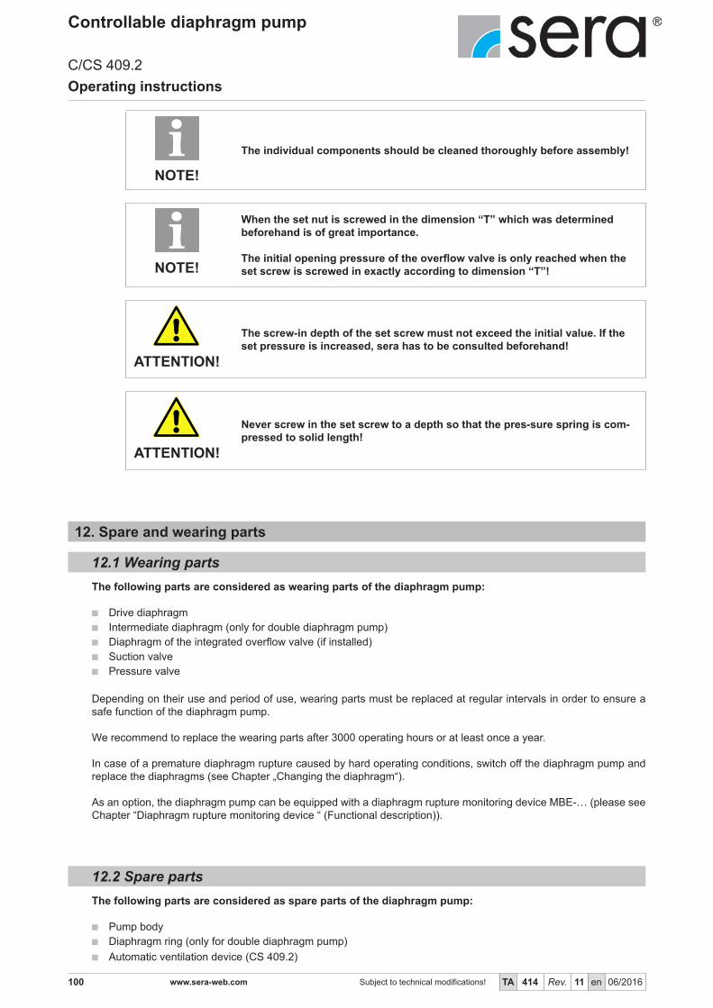
100 www.sera-web.com Subject to technical modifications! TA 414 Rev. 11 en 06/2016
Controllable diaphragm pump
C/CS 409.2Operating instructions
Automatic ventilation device (CS 409.2)
The individual components should be cleaned thoroughly before assembly!
NOTE!
When the set nut is screwed in the dimension “T” which was determined beforehand is of great importance.
The initial opening pressure of the overflow valve is only reached when the set screw is screwed in exactly according to dimension “T”!NOTE!
The screw-in depth of the set screw must not exceed the initial value. If the set pressure is increased, sera has to be consulted beforehand!
ATTENTION!
Never screw in the set screw to a depth so that the pres-sure spring is com-pressed to solid length!
ATTENTION!
The following parts are considered as wearing parts of the diaphragm pump:
Drive diaphragm Intermediate diaphragm (only for double diaphragm pump) Diaphragm of the integrated overflow valve (if installed) Suction valve Pressure valve
Depending on their use and period of use, wearing parts must be replaced at regular intervals in order to ensure a safe function of the diaphragm pump.
We recommend to replace the wearing parts after 3000 operating hours or at least once a year.
In case of a premature diaphragm rupture caused by hard operating conditions, switch off the diaphragm pump and replace the diaphragms (see Chapter „Changing the diaphragm“).
As an option, the diaphragm pump can be equipped with a diaphragm rupture monitoring device MBE-… (please see Chapter “Diaphragm rupture monitoring device “ (Functional description)).
The following parts are considered as spare parts of the diaphragm pump:
Pump body Diaphragm ring (only for double diaphragm pump)
12. Spare and wearing parts
12.2 Spare parts
12.1 Wearing parts

101TA 414 Rev. 11 en 06/2016 Subject to technical modifications! www.sera-web.com
Controllable diaphragm pump
C/CS 409.2Operating instructions
12.3 Spare and wearing parts
12.3.1 Diaphragm pump C 409.2- 0,8 e ...-2,4 e
2
7
4
5
6
3
1
1
8
9
C409.2 - 0,8eC409.2 - 1,6eC409.2 - 2,4e
Overview of the spare and wearing part kits Diaphragm pump C 409.2- 0,8 e ...-2,4 e
Suction valve (kit) Pump body kit (plastic, FRP-design)
Pos. consisting of Pos. consisting of
8 Suction valve (incl. o-rings) 1 Vent valve
2 Screws, complete
Pressure valve (kit) 3 Pump body
Pos. consisting of
4 Pressure valve (incl. o-rings) Pump body kit (plastic)
Pos. consisting of
Diaphragm kit 5 Screws, complete
Pos. consisting of 6 Front plate
9 Drive diaphragm 7 Pump body

102 www.sera-web.com Subject to technical modifications! TA 414 Rev. 11 en 06/2016
Controllable diaphragm pump
C/CS 409.2Operating instructions
2
7
4
5
6
3
18
9
10
11
12
13
12.3.2 Diaphragm pump C 409.2- 4,0 (e) ...-180 (e)
C409.2 - 4,0 (e)C409.2 - 7,0 (e)C409.2 - 12 (e)C409.2 - 18 (e)C409.2 - 25 (e)C409.2 - 50 (e)C409.2 - 75 (e)C409.2 - 90 (e)C409.2 - 115 (e)C409.2 - 140 (e)C409.2 - 180 (e)

103TA 414 Rev. 11 en 06/2016 Subject to technical modifications! www.sera-web.com
Controllable diaphragm pump
C/CS 409.2Operating instructions
Overview of the spare and wearing part kitsDiaphragm pump C 409.2- 4,0 (e) ...-180 (e)
Suction valve (kit) Pump body kit (plastic, FRP-design)
Pos. consisting of Pos. consisting of
9 Suction valve (incl. o-rings) 1 Cover plate
2 Screws, complete
Pressure valve (kit) 3 Insertion plate(s), if applicable
Pos. consisting of 4 Pump body
5 Pressure valve (incl. o-rings)
Pump body kit (plastic)
Diaphragm kit (single diaphragm pump) Pos. consisting of
Pos. consisting of 6 Screws, complete
12 Drive diaphragm 7 Front plate
13 Pressure plate 8 Pump body
(not with a laminated drive diaphragm)
Pump body kit (special steel)
Diaphragm kit (double diaphragm pump) Pos. consisting of
Pos. consisting of 6 Screws, complete
10 Intermediate diaphragm 8 Pump body
12 Drive diaphragm
13 Pressure plate
(not with a laminated drive diaphragm)
Buffer fluid
Diaphragm ring kit (only for double diaphragm pump)
Pos. consisting of
11 Diaphragm ring, complete

104 www.sera-web.com Subject to technical modifications! TA 414 Rev. 11 en 06/2016
Controllable diaphragm pump
C/CS 409.2Operating instructions
2
7
4
5
6
3
1
8
12.3.3 Diaphragm pump C 409.2-250 (e) ...-350 (e)
C409.2 - 250 (e)C409.2 - 350 (e)

105TA 414 Rev. 11 en 06/2016 Subject to technical modifications! www.sera-web.com
Controllable diaphragm pump
C/CS 409.2Operating instructions
Overview of the spare and wearing part kits Diaphragm pump C 409.2-250 (e) ...-350 (e)
Suction valve (kit) Pump body kit (plastic)
Pos. consisting of Pos. consisting of
5 Suction valve (incl. o-rings) 1 Screws, complete
2 Front plate
Pressure valve (kit) 3 Pump body
Pos. consisting of
4 Pressure valve (incl. o-rings) Pump body kit (special steel)
Pos. consisting of
Diaphragm kit (single diaphragm pump) 1 Screws, complete
Pos. consisting of 3 Pump body
8 Drive diaphragm
Diaphragm kit (double diaphragm pump)
Pos. consisting of
6 Intermediate diaphragm
8 Drive diaphragm
Buffer fluid
Diaphragm ring kit (only for double diaphragm pump)
Pos. consisting of
7 Diaphragm ring, complete

106 www.sera-web.com Subject to technical modifications! TA 414 Rev. 11 en 06/2016
Controllable diaphragm pump
C/CS 409.2Operating instructions
2
7
4
6
3
1
8
9 10
11
12
13
1415
16
175
12.3.4 Diaphragm pump C 409.2- 4,0 (e) ...-180 (e) with integrated overflow valve
C409.2 - 4,0 (e)C409.2 - 7,0 (e)C409.2 - 12 (e)C409.2 - 18 (e)C409.2 - 25 (e)C409.2 - 50 (e)C409.2 - 75 (e)C409.2 - 90 (e)C409.2 - 115 (e)C409.2 - 140 (e)C409.2 - 180 (e)
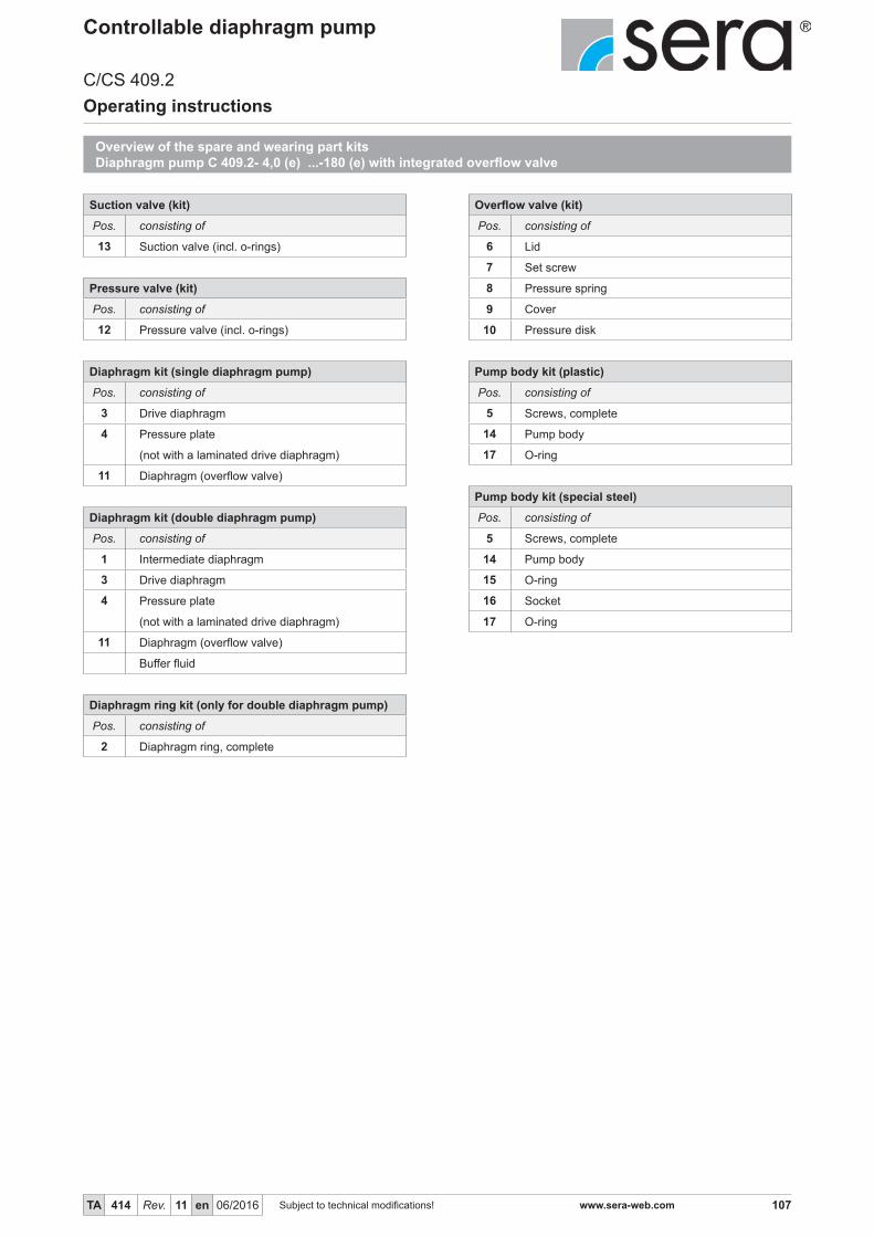
107TA 414 Rev. 11 en 06/2016 Subject to technical modifications! www.sera-web.com
Controllable diaphragm pump
C/CS 409.2Operating instructions
Overview of the spare and wearing part kits Diaphragm pump C 409.2- 4,0 (e) ...-180 (e) with integrated overflow valve
Suction valve (kit) Overflow valve (kit)
Pos. consisting of Pos. consisting of
13 Suction valve (incl. o-rings) 6 Lid
7 Set screw
Pressure valve (kit) 8 Pressure spring
Pos. consisting of 9 Cover
12 Pressure valve (incl. o-rings) 10 Pressure disk
Diaphragm kit (single diaphragm pump) Pump body kit (plastic)
Pos. consisting of Pos. consisting of
3 Drive diaphragm 5 Screws, complete
4 Pressure plate 14 Pump body
(not with a laminated drive diaphragm) 17 O-ring
11 Diaphragm (overflow valve)
Pump body kit (special steel)
Diaphragm kit (double diaphragm pump) Pos. consisting of
Pos. consisting of 5 Screws, complete
1 Intermediate diaphragm 14 Pump body
3 Drive diaphragm 15 O-ring
4 Pressure plate 16 Socket
(not with a laminated drive diaphragm) 17 O-ring
11 Diaphragm (overflow valve)
Buffer fluid
Diaphragm ring kit (only for double diaphragm pump)
Pos. consisting of
2 Diaphragm ring, complete

108 www.sera-web.com Subject to technical modifications! TA 414 Rev. 11 en 06/2016
Controllable diaphragm pump
C/CS 409.2Operating instructions
2
7
4
6
3
1
8
910
1516
175
1211
1413
18
19
20
12.3.5 Diaphragm pump C 409.2-250 (e) ...-350 (e) with integrated overflow valve
C409.2 - 250 (e)C409.2 - 350 (e)

109TA 414 Rev. 11 en 06/2016 Subject to technical modifications! www.sera-web.com
Controllable diaphragm pump
C/CS 409.2Operating instructions
Overview of the spare and wearing part kits Diaphragm pump C 409.2-250 (e) ...-350 (e) with integrated overflow valve
Suction valve (kit) Overflow valve (kit)
Pos. consisting of Pos. consisting of
17 Suction valve (incl. o-rings) 9 Lid
10 Set screw
Pressure valve (kit) 11 Pressure spring
Pos. consisting of 12 Pressure spring
8 Pressure valve (incl. o-rings) 13 Hexagon screw(s)
14 Disk(s)
Diaphragm kit (single diaphragm pump) 15 Cover
Pos. consisting of 16 Pressure disk
3 Drive diaphragm
6 Diaphragm (overflow valve) Pump body kit (plastic)
Pos. consisting of
Diaphragm kit (double diaphragm pump) 4 Screws, complete
Pos. consisting of 5 Front plate
1 Intermediate diaphragm 7 Pump body
3 Drive diaphragm 20 O-ring
6 Diaphragm (overflow valve)
Buffer fluid Pump body kit (special steel)
Pos. consisting of
Diaphragm ring kit (only for double diaphragm pump) 4 Screws, complete
Pos. consisting of 7 Pump body
2 Diaphragm ring, complete 18 O-ring
19 Socket
20 O-ring

110 www.sera-web.com Subject to technical modifications! TA 414 Rev. 11 en 06/2016
Controllable diaphragm pump
C/CS 409.2Operating instructions
12.3.6 Diaphragm pump CS 409.2- 0,8 e ...-2,4 e
CS409.2 - 0,8 eCS409.2 - 1,6 eCS409.2 - 2,4 e
2
7
4
5
63
1

111TA 414 Rev. 11 en 06/2016 Subject to technical modifications! www.sera-web.com
Controllable diaphragm pump
C/CS 409.2Operating instructions
Overview of the spare and wearing part kits Diaphragm pump CS 409.2- 0,8 e ...-2,4 e
Suction valve (kit) Pump body kit (plastic)
Pos. consisting of Pos. consisting of
6 Suction valve (incl. o-rings) 3 Screws, complete
4 Front plate
Pressure valve (kit) 5 Pump body
Pos. consisting of
2 Pressure valve (incl. o-rings) Automatic ventilation device -kit
Pos. consisting of
Diaphragm kit 1 Automatic ventilation device (incl. o-ring)
Pos. consisting of
7 Drive diaphragm

112 www.sera-web.com Subject to technical modifications! TA 414 Rev. 11 en 06/2016
Controllable diaphragm pump
C/CS 409.2Operating instructions
2
7
4
5
6
3
1
8
910
11
12
12.3.7 Diaphragm pump CS 409.2- 4,0 (e) ...-25 (e)
CS409.2 - 4,0 (e)CS409.2 - 7,0 (e)CS409.2 - 12 (e)CS409.2 - 18 (e)CS409.2 - 25 (e)

113TA 414 Rev. 11 en 06/2016 Subject to technical modifications! www.sera-web.com
Controllable diaphragm pump
C/CS 409.2Operating instructions
Overview of the spare and wearing part kitsDiaphragm pump CS 409.2- 4,0 (e) ...-25 (e)
Suction valve (kit) Pump body kit (FRP-design)
Pos. consisting of Pos. consisting of
8 Suction valve (incl. o-rings) 5 Cover plate
6 Screws, complete
Pressure valve (kit) 7 Pump body
Pos. consisting of
4 Pressure valve (incl. o-rings) Pumpenkörper-Set (PVC)
Pos. consisting of
Diaphragm kit (single diaphragm pump) 1 Screws, complete
Pos. consisting of 2 Pump body
11 Drive diaphragm
12 Pressure plate Entlüftungsautomatik-Set
(not with a laminated drive diaphragm) Pos. consisting of
3 Automatic ventilation device (incl. o-ring)
Diaphragm kit (double diaphragm pump)
Pos. consisting of
9 Intermediate diaphragm
11 Drive diaphragm
12 Pressure plate
(not with a laminated drive diaphragm)
Buffer fluid
Diaphragm ring kit (only for double diaphragm pump)
Pos. consisting of
10 Diaphragm ring, complete

114 www.sera-web.com Subject to technical modifications! TA 414 Rev. 11 en 06/2016
Controllable diaphragm pump
C/CS 409.2Operating instructions
2
7
4
6
3
1
8
9
10
11
12
1314
15
5
1617
12.3.8 Diaphragm pump CS 409.2- 4,0 (e) ...-25 (e) with integrated overflow valve
CS409.2 - 4,0 (e)CS409.2 - 7,0 (e)CS409.2 - 12 (e)CS409.2 - 18 (e)CS409.2 - 25 (e)

115TA 414 Rev. 11 en 06/2016 Subject to technical modifications! www.sera-web.com
Controllable diaphragm pump
C/CS 409.2Operating instructions
Overview of the spare and wearing part kitsDiaphragm pump CS 409.2- 4,0 (e) ...-25 (e) with integrated overflow valve
Suction valve (kit) Overflow valve (kit)
Pos. consisting of Pos. consisting of
10 Suction valve (incl. o-rings) 2 Lid
3 Set screw
Pressure valve (kit) 4 Pressure spring
Pos. consisting of 5 Cover
8 Pressure valve (incl. o-rings) 6 Pressure disk
Diaphragm kit (single diaphragm pump) Pump body kit (plastic)
Pos. consisting of Pos. consisting of
15 Drive diaphragm 1 Screws, complete
16 Pressure plate 11 Pump body
(not with a laminated drive diaphragm) 12 O-ring
7 Diaphragm (overflow valve)
Automatic ventilation device -kit
Diaphragm kit (double diaphragm pump) Pos. consisting of
Pos. consisting of 9 Automatic ventilation device (incl. o-ring)
13 Intermediate diaphragm
15 Drive diaphragm
16 Pressure plate
(not with a laminated drive diaphragm)
7 Diaphragm (overflow valve)
Buffer fluid
Diaphragm ring kit (only for double diaphragm pump)
Pos. consisting of
14 Diaphragm ring, complete

116 www.sera-web.com Subject to technical modifications! TA 414 Rev. 11 en 06/2016
Controllable diaphragm pump
C/CS 409.2Operating instructions
13. Fault analysis and corrective actionsera products are sophisticated technical products which are only shipped after having been thoroughly tested and che-cked at our factory.Should there be any faults, these can be – on account of fault announcement on LCD-display – detected and rectified easily and quickly if the steps in Tables are carried out.
13.1 Analysis of the plain text error messages
Error message Possible cause Corrective action
Ana
log
sign
al <
4 m
A!
Ana
log
sign
al >
20
mA
!
Ana
log
sign
al >
25
mA
!
Flow
too
low
!
Cyc
le-d
elay
mem
ory
full!
Leav
e th
e ca
libra
tion
rang
e!N
o st
roke
reco
gniti
on!
(inte
rnal
faul
t)
No
flow
!
Wire break of the analog signal line. Check analog signal line and repair, if necessary.
The set analog signal (e.g. 4-20mA) does not match the actual analog signal (e.g. 0-20mA).
Check the set analog signal and adapt to the actual analog signal, if necessary.
Fault of the analog signal transmitter (sensor, controller).
Check the analog signal transmitter and eli-minate fault of the transmitter if necessary.
Drive diaphragm defective. Replace drive diaphragm.
Suction height too high. Reduce suction height or suction resi-stance.
Suction line leaky. Check gaskets, tighten pipe connections.
Shut-off valves in pipe closed. Open shut-off valves or check opening – check pump for damage.
Few or no conveying medium in store tank. Fill store tank.
Pump valves leaky. Remove valves and clean.
Foreign matter in pump valves or Pump valves (ball seats) damaged.
Remove and clean valves, check function; replace valves if necessary.
Pump valves incorrectly mounted or valve balls missing.
Check installation position and comple-teness – replace missing parts or install correctly.
Filter in suction line clogged. Clean filter.
No stroke movement of the drive dia-phragm.
Increase stroke frequency / stroke length; check connecting rod motion.
Counter-pressure too high.Measure pressure with manometer directly above pressure valve and compare with permissible counter-pressure.
Acceleration height too high due to pipe geometry.
Check acceleration height on suction- and pressure side and compare with design data – install a pulsation damper if neces-sary.
Too high viscosity of the pumped medium.
Check viscosity of the pumped medium and compare with the design data – reduce concentration or increase temperature if necessary.

117TA 414 Rev. 11 en 06/2016 Subject to technical modifications! www.sera-web.com
Controllable diaphragm pump
C/CS 409.2Operating instructions
Pumped medium outgasses in suction line and/or pump body.
Check geodetic conditions and compare with the data of the pumped medium. Ope-rate pump with suction side supply, reduce temperature of the pumped medium.
Air in suction line while pressure applied to the pressure valve ball.
Vent pressure side resp. open vent valve (only FRP-design, see chap. „Manual vent valve“ (Functional description)).
Pipe connections leaky.Tighten connection according to type of material. Be careful with plastic – risk of fracture
Pumped medium frozen in pipe.Remove diaphragm pump and check for damage – increase temperature of the pumped medium.
Pump valves are dry. Moisten pump body and valves. Open vent valve.
Frequency of the received pulses is (permanently) higher than the maximum stroke frequency of the dosing pump.
Check process parameters.
Pulse factor too high. Check process parameters.
After calibration of the dosing pump the stroke length was adjusted by more than +/- 10%.
Check the stroke length adjustment, set the set value again, calibrate again, if necessary.
Stroke length was set to below 15% approx., the stroke length is out of the linear dosing range.
Check the stroke length adjustment, incre-ase the stroke length.
Sensory mechanism of dosing pump is defective. Contact the manufacturer.
Error message Possible cause Corrective action
Ana
log
sign
al <
4 m
A!
Ana
log
sign
al >
20
mA
!
Ana
log
sign
al >
25
mA
!
Flow
too
low
!
Cyc
le-d
elay
mem
ory
full!
Leav
e th
e ca
libra
tion
rang
e!N
o st
roke
reco
gniti
on!
(inte
rnal
faul
t)
No
flow
!

118 www.sera-web.com Subject to technical modifications! TA 414 Rev. 11 en 06/2016
Controllable diaphragm pump
C/CS 409.2Operating instructions
Error message Possible cause Corrective action
Dia
phra
gm ru
ptur
e!
Mai
ns v
olta
ge to
o g
too
low
!
Mai
ns v
olta
ge to
o hi
gh!
Pre
-ala
rm le
vel!
Set
val
ue n
ot a
ttain
able
! (In
tern
al fa
ult!!
)
Faul
t driv
e! (I
nter
nal f
ault!
)
Faul
t stro
ke s
enso
r!!
(Inte
rnal
faul
t!!)
Dry
runn
ing
of d
osin
g pu
mp!
Drive diaphragm defective. Replace drive diaphragm.
Electric data of the dosing pump do not match mains data.
Check order data. Check electric installation.
Few or no conveying medium in store tank. Fill store tank.
Only for calibrated pump: Set stroke length is too low to attain the preset set value.
Check the stroke length and the set value, calibrate the pump again, if necessary.
Integrated excess temperature protection (posistor) of drive motor released.
Let the temperature of the drive motor go down. Check the ambient temperature.
No stroke movement of the drive dia-phragm.
Increase stroke frequency / stroke length; check connecting rod motion.
Counter-pressure too high.Measure pressure with manometer directly above pressure valve and compare with permissible counter-pressure.
Shut-off valves in pipe closed. Open shut-off valves or check opening – check pump for damage.
13.2 Analysis of other faults
Type of fault Possible cause Fault clearance
Dia
phra
gm p
ump
does
not
dra
w in
Dia
phra
gm p
ump
does
not
del
iver
Del
iver
y ra
te is
not
reac
hed
Del
iver
y he
ight
is n
ot re
ache
d
Del
iver
y ra
te fl
uctu
ates
Max
imum
del
iver
y ra
te e
xcee
ded
Driv
e m
otor
doe
s no
t sta
rt
Pip
e os
cilla
tes
heav
ily
Hig
h no
ise
deve
lopm
ent
Low
ser
vice
life
of t
he d
rive
diap
hrag
m
Driv
e is
ove
rload
ed
Dam
age
in s
troke
mec
hani
sm /
driv
e
Leak
age
on p
ump
head
Suction height too high. Reduce suction height or suction resi-stance.
Suction line leaky. Check gaskets, tighten pipe connections.
Shut-off valves in pipe closed. Open shut-off valves or check opening – check pump for damage.
No conveying medium in store tank. Fill store tank.
Pump valves leaky. Remove valves and clean.

119TA 414 Rev. 11 en 06/2016 Subject to technical modifications! www.sera-web.com
Controllable diaphragm pump
C/CS 409.2Operating instructions
Type of fault Possible cause Fault clearance
Dia
phra
gm p
ump
does
not
dra
w in
Dia
phra
gm p
ump
does
not
del
iver
Del
iver
y ra
te is
not
reac
hed
Del
iver
y he
ight
is n
ot re
ache
d
Del
iver
y ra
te fl
uctu
ates
Max
imum
del
iver
y ra
te e
xcee
ded
Driv
e m
otor
doe
s no
t sta
rt
Pip
e os
cilla
tes
heav
ily
Hig
h no
ise
deve
lopm
ent
Low
ser
vice
life
of t
he d
rive
dia-
phra
gmD
rive
is o
verlo
aded
Dam
age
in s
troke
mec
hani
sm /
driv
e
Leak
age
on p
ump
head
Pump valves (ball seats) dama-ged.
Remove and clean valves, check function; replace valves if necessary.
Pump valves incorrectly mounted or valve balls missing.
Check installation position and comple-teness – replace missing parts or install correctly.
Filter in suction line clogged. Clean filter.
Electric data of the electronics do not match mains data.
Check order data. Check electric installa-tion.
Counter-pressure too high.Measure pressure with manometer directly above pressure valve and compare with permissible counter-pressure.
Foreign matter in pump valves. Remove and clean valves.
Pressure on suction side higher than at the end of the pressure line.
Check geodetic conditions, install float val-ve or pressure keeping valve if necessary.
Acceleration height too high due to pipe geometry.
Check acceleration height on suction- and pressure side with manometer and com-pare with design data – install a pulsation damper if necessary.
Material which is in contact with the medium not suitable for the pumped medium.
Check whether the pumped medium cor-responds with the design data and select other materials if necessary.
Too high viscosity of the pumped medium.
Check viscosity of the pumped medium and compare with the design data – reduce concentration or increase temperature if necessary.
Pumped medium outgasses in suction line.
Check geodetic conditions and compare with the data of the pumped medium. Ope-rate pump with suction side supply, reduce temperature of the pumped medium.
Air in suction line while pressure ap-plied to the pressure valve ball.
Vent pressure side resp. open vent valve (only FRP-design C409.2-0,8e- …2,4e).
Pipe connections leaky.Tighten connection according to type of material. Be care-ful with plastic – risk of fracture.
Temperature too low.Check flowability of the pumped medium. Temperature of pumped medium and ambi-ent temperature must not fall below -10°C.
Pumped medium frozen in pipe.Remove diaphragm pump and check for damage – in-crease temperature of the pumped medium.
Diaphragm rupture. Replace diaphragm according to Chapter „Changing the Diaphragm“.

120 www.sera-web.com Subject to technical modifications! TA 414 Rev. 11 en 06/2016
Controllable diaphragm pump
C/CS 409.2Operating instructions
Switch off piston diaphragm pump. Rinse pump head and remove pumped medium; make sure that the rinsing agent is suitable for pumped medium
and pump head.
Shut-down system. Please see “Shut-down“.
Shut-down system. Please see “Shut-down“. Remove all fluid residues from pump body, clean thoroughly, neutralize and decontaminate. Package unit and ship.
A clearance certificate must be filled in when systems are returned to the manuf-acturer (see Chapter 16). Acceptance will be rejected if this clearance certificate is not attached.NOTE!
The consignor is responsible for leaking lubricants or fluids!
WARNING!
14. Shut-down
Remove all fluid residues from unit. Drain off lubricants and dispose of according to regulations! Dismount materials and send them to a suitable waste disposal company!
The consignor is responsible for leaking lubricants or fluids!
WARNING!
15.2 Complete disposal
15.1 Dismantling and transport
15. Disposal

121TA 414 Rev. 11 en 06/2016 Subject to technical modifications! www.sera-web.com
Controllable diaphragm pump
C/CS 409.2Operating instructions
16. Clearance Certificate
Inspection / repair of machines and machine parts is only carried out after the op-posite clearance certificate was filled in correctly and completely by authorized and qualified personnel.
NOTE!
Acceptance will be refused if parts are returned to the manufacturer without a properclearance certificate.
NOTE!
All industrial companies are obligated by the legal provisions for occupational health, e.g. the workplaces ordinances,the Ordinance on Hazardous Substances, the regulations for prevention of accidents and the environmental protectionregulations such as the Waste Management Act and the German Household Water Act to protect their employees orman and the environment from detrimental effects when handling hazardous substances.
Should special safety precautions be necessary despite careful draining and cleaning of the productthe necessary information are to be provided.
Machines which are operated with radioactive media shall only be inspected and/or repaired in thesafety area of the owner by a sera specialized fitter.
The clearance certificate is part of the inspection-/repair order.sera reserves the right to refuse acceptance of the order for other reasons.
Please make a copy and leave the original with the operating instructions!(can also be downloaded from: www.sera-web.com)
NOTE!

122 www.sera-web.com Subject to technical modifications! TA 414 Rev. 11 en 06/2016
Controllable diaphragm pump
C/CS 409.2Operating instructions
1
Clearance Certificate
www.sera-web.com
QS
F 46
9-01
en
/ 11.
2014
/ P
M
ProductType Serial-No.
the product was carefully emptied before shipping / delivery, and cleaned inside and outside. YES
Conveying mediumDesignation Concentration %
Properties
Please tick!
If either of the listed properties, then enclose the appropriate safety and handling instruc-tions.
The product was used with health or water-polluting substances and came up with labeling requirements and pollution prone media in contact.
YES
NO
Special security arrangements with respect to health or water-hazardous mediaare in the further handling
not required
required
The following safety precautions regarding rinsing, residual liquids and waste disposal are required:
Process dataThe product was used with the following operating conditions described conveying medium:
Temperature °C Pressure bar
Sender
Company: Telephone:
Contact person: FAX:
Address: E-mail:
Zip code, City: Your order No:
We confirm that we have the information in this safety certificate (Clearance Certificate) have been correctly and completely and that the returned parts were carefully cleaned. The parts are sent free of residues of dangerous amount.
Place, Date Department Signature(and company stamp)
Corrosive
Flammable
Oxidising
Unhealthy
Toxic
Harmless
Dangerous for
the environment
Bio-
hazardous
Radioactive
Explosive
Irritant

123TA 414 Rev. 11 en 06/2016 Subject to technical modifications! www.sera-web.com
Controllable diaphragm pump
C/CS 409.2Operating instructions
NOTES
