ccs centralised conveying systems...
TRANSCRIPT

Manual
R2466
CCS – Centralised Conveying Systems
Labo-Scan
Serial No....................
ISO 08.01.02.058.GB LT nr.: 986891
Rev. 01
Rev.00 CCS-Centralised Conveying Systems – Labo-Scan Page 2 of 42
1.0 CONTENTS
2.0 GENERAL INFORMATION ............................................................................. 4
2.1 Application ......................................................................................................................... 4
2.2 Restrictions......................................................................................................................... 4
2.3 Design ................................................................................................................................ 4
2.4 Relevant standards, instructions, directives etc. .................................................................... 8
2.5 Operating principles ............................................................................................................ 8
2.6 Certificates ....................................................................................................................... 12
3.0 TECHNICAL DATA......................................................................................... 13
3.1 Type plate ........................................................................................................................ 13
3.2 Dimensioned drawing of vacuum station, example ............................................................. 14 3.3 Capacity ........................................................................................................................... 14
4.0 ASSEMBLY ....................................................................................................... 15
4.1 Fitting the main components ............................................................................................. 15
4.2 Connections ...................................................................................................................... 16
5.0 USERS MANUAL ............................................................................................. 17
5.1 System setup..................................................................................................................... 17
5.2 Operating the system......................................................................................................... 25
5.3 Alarms ............................................................................................................................. 31
5.4 Start ................................................................................................................................. 32
5.5 Stop.................................................................................................................................. 33
5.6 Screen overview ............................................................................................................... 34
6.0 ACCESSORIES ................................................................................................. 35
7.0 MAINTENANCE .............................................................................................. 36
7.1 Maintaining the Labo-Scan control .................................................................................... 36
7.2 Maintaining the central filter, WAM .................................................................................. 36
7.3 Maintaining the vacuum blowers and the valves ................................................................ 36
8.0 TROUBLESHOOTING .................................................................................... 37
8.1 Troubleshooting generally ................................................................................................. 37
8.2 The system stops short ...................................................................................................... 38
8.3 Reduced or stopped conveying of raw material to several or all vacuum receivers .............. 39 8.4 Reduced or stopped conveying of raw material to some of the vacuum receivers ................ 40
9.0 REPAIRS ........................................................................................................... 41
9.1 Replacing the bottom flap vacuum receiver PGT ............................................................... 41
9.2 Replacing the bottom flap vacuum receiver SVR (stainless) ............................................... 42

Rev.00 CCS-Centralised Conveying Systems – Labo-Scan Page 3 of 42
NB! All electrical diagrams can be found in the pocket in the back of the manual.

Rev.00 CCS-Centralised Conveying Systems – Labo-Scan Page 4 of 42
2.0 GENERAL INFORMATION
2.1 Application
Labotek’s conveying system is a computerized, in-plant system designed for handling the raw
materials optimally at all levels. The system is fitted with a central blower and a control to ensure
supply of raw materials to each processing machine as required.
The system is designed, dimensioned and customised in accordance with the individual customer’s
machine layout, requirements and requests.
The system is suitable to convey all types of free-flowing granules. An integrated central dust filter
system protects the environment against pollution.
The individual vacuum receivers (PGT or SVR) can be mounted at or combined with Labotek’s
drying or dosing equipment.
2.2 Restrictions
The system may only be used for the purposes specified.
The system cannot be used for powders or liquids, or for living creatures.
The system must be used by qualified operators only, following the correct procedures.
The system may not be located in areas where there is any danger of explosion.
2.3 Design
The design of the system is based on the basic principle of suction air conveying and may consist of the following main components (see the above drawing).
R2618

Rev.00 CCS-Centralised Conveying Systems – Labo-Scan Page 5 of 42
1. Vacuum station
Used to generate the vacuum necessary to convey the plastic materials.
The vacuum station is supplied as a compact unit consisting of a vacuum blower with motor
protection, a central self-purifying dust filter and piping and valve arrangement.
Alternatively, the central self-purifying filter may be substituted for a built-in return air valve which
is reversing the air flow in the system and by air cleaning the filters fitted in the vacuum receivers
(pos. 2).
2. Vacuum receivers (PGT or SVR) To be mounted on the processing machinery. The capacity of the vacuum receivers corresponds to
the hourly capacity of each processing machine.
3. Labo-Scan control
Used to collate and coordinate all processes of the system.
4. Line clearing valves
To be fitted by the silo(s) / drying hopper(s) to ensure that the material lines are completely cleared
after each conveying cycle so to avoid plugging effectively.
Alternatively, pneumatic slide valves may be fitted under the silo(s) / drying hopper(s). They are
used to clear the material lines and to ensure that an equal amount of material is conveyed in each
cycle.
The system is designed to incorporate Labotek’s other range of equipment such as:
5. Hot air dryer type CD (not shown on drawing) Used to dry and condition non-hygroscopic raw materials.
6. Dry air dryer type DDL, DFD and MDFD (MDFD shown on drawing)
Used to dry hygroscopic raw materials.
To ensure a reliable production it is recommended to install dry air dryers in areas where the R.H.
(relative humidity) varies according to season or is constantly high even though the material is
categorized as less hygroscopic.
7. Dosing and mixing equipment type Gravimix or RS (RS type IDV shown on drawing)
Gravimix is especially designed for gravimetric blending of main materials, regrind, master batch
and other additives.
The Ratio-Selector type RS is designed for mixing two main materials or a main material with
regrinds.
8. Mobile dryer type DDM (not shown on drawing)
Adds to the flexibility of the production process as the unit can be moved about as necessary.
9. Self-purifying filter WAM
The filter is located between the vacuum station and the vacuum receivers and is cleaned after each
conveying cycle.

Rev.00 CCS-Centralised Conveying Systems – Labo-Scan Page 6 of 42
2.3.1 Vacuum station
The vacuum station unit is as standard supplied with a control cabinet, a filter, not less than one
vacuum blower and all connecting pipes necessary to make the unit fully operational.
The control cabinet, which is made of japanned metal plate, contains all electrical components
required for start and operation of the vacuum station. The electrical motor for each vacuum blower
is fitted with a contactor with thermal overload relay.
The electrical motor of the vacuum blower is supplied with across-the-line starting as standard.
Systems incorporating more than one vacuum blower are fitted with a delay module to minimize
start current for the whole vacuum station.
The front of the cabinet serves also as a door on which a combined safety cut-out and main switch
is fitted. The type plate of the vacuum station is located at the cabinet.
To avoid several successive power consuming starts-ups of the vacuum blower the control is fitted with a time delay function allowing the blower to run on for 20 to 120 seconds after the conveying
has stopped.
Fresh air valve The vacuum blower is equipped with a fresh air valve which opens when the blower is running
without admitting air for material conveying. Valve shut off time is adjustable between 60-120
seconds.
The vacuum station base support is designed to allow location detached or against the wall. It may also hang on the wall, if the wall is strong enough. The base support is equipped with holes for
fastening. The triangular supporting leg may be dismantled if the vacuum station is to hang on the
wall.
Safety valve
To prevent overloading of the blower e.g. by blockage of the vacuum pipe, a safety valve, which
opens automatically if the vacuum exceeds a certain level, is fitted at the inlet side of the blower.
Frequency converter Option. The frequency controller is set in % air speed hereby each station may have its individual
air speed setting depending on the character of the material being conveyed. Raw materials are
gently conveyed and piping system/hoses has increased lifespan. Energy is saved as well.
Filters
The vacuum station may be supplied with one of the following type of filters:
Self-purifying filter
The filter is located between the vacuum station and the vacuum receivers and is cleaned after each conveying cycle. The self-purifying filter may only be used for cleaning vacuum air in the plant in
which it is fitted.
For information on WAM filters, see separate manual.
Blow-back valve
The valve is used to reverse the air flow from the vacuum blower and by air to clean the filter in the
vacuum receiver between conveying cycles.

Rev.00 CCS-Centralised Conveying Systems – Labo-Scan Page 7 of 42
Cyclone
Filters the air continuously.
2.3.2 Vacuum receivers
The vacuum receivers are made of cast aluminium or stainless steel and come ready-fitted with
bottom flap arrangement (level control) and vacuum valve. The vacuum valve is operated by
compressed air and is activated by a solenoid valve (for 24 VAC).
Type of vacuum valve is identical with the line clearing valve mentioned in section 2.3.4.
2.3.3 Labo-Scan control
The Labo-Scan control consists of a Siemens PLC with a TP 177 MICRO control panel.
R2627
2.3.4 Line clearing valve
The line clearing valve is a single-acting, normally closed 2-way seat valve fitted with a solenoid
valve.
The line clearing valve opens by means of compressed air and, via a return spring, it closes up at
release of pressure (see section 2.3.5).
The closing movement of the valve is controlled by throttling the ventilating side of the solenoid
valve. The valve arrangement is made of plated steel and aluminium.
The valve is fitted at a Ø50mm pipe branch by compression of an O-ring.

Rev.00 CCS-Centralised Conveying Systems – Labo-Scan Page 8 of 42
2.3.5 Piping system
Labotek’s specially designed piping system is made of aluminium pipes as standard with fittings
made of stainless steel.
Standard diameters of the system are: Ø38 and Ø50mm.
2.3.6 Non-return flap in vacuum receiver
The non-return flap consists of a silicone gasket (52) and a non-return flap (51) fitted at the inlet
pipe (50) of the vacuum receiver.
A non-return flap is fitted in either of the following two cases:
1. The piping system incorporates a coupling station.
2. A common material pipe is used for several machines.
3. If the vacuum station is fitted with blow-back valve.
The non-return flap ensures that false air is not admitted to the system from several vacuum
receivers. At worst it may cause material to be sucked from one vacuum receiver to the other
through the entire piping system.
R1805
2.4 Relevant standards, instructions, directives etc.
Directive no. 2006/95/EU (the Low-voltage Directive).
Directive no. 2004/108/ (the EMC directive).
Directive no. 2006/42/EU (the Machinery Directive).
2.5 Operating principles
2.5.1 Conveying
The vacuum receivers are fitted with a bottom flap. The bottom flap acts as level control and
controls the raw material level continuously.
The Labo-Scan control registers the level in any of the connected vacuum hoppers and at the indication of low level the vacuum station is activated.
The conveying cycles take place in a pre adjusted time corresponding to the time it takes to fill the
vacuum receiver.
To ensure an easy and unobstructed material flow the line clearing valves open (if fitted), and the
pipe lines are cleared so to prevent material from piling up.

Rev.00 CCS-Centralised Conveying Systems – Labo-Scan Page 9 of 42
2.5.2 Design
Conveying of raw material is, in principle, based on a number of conveying cycles. Each processing
machine is fitted with a vacuum receiver designed to meet both the required capacity and the
requirement for quick change of material and colour.
2.5.3 Conveying cycle
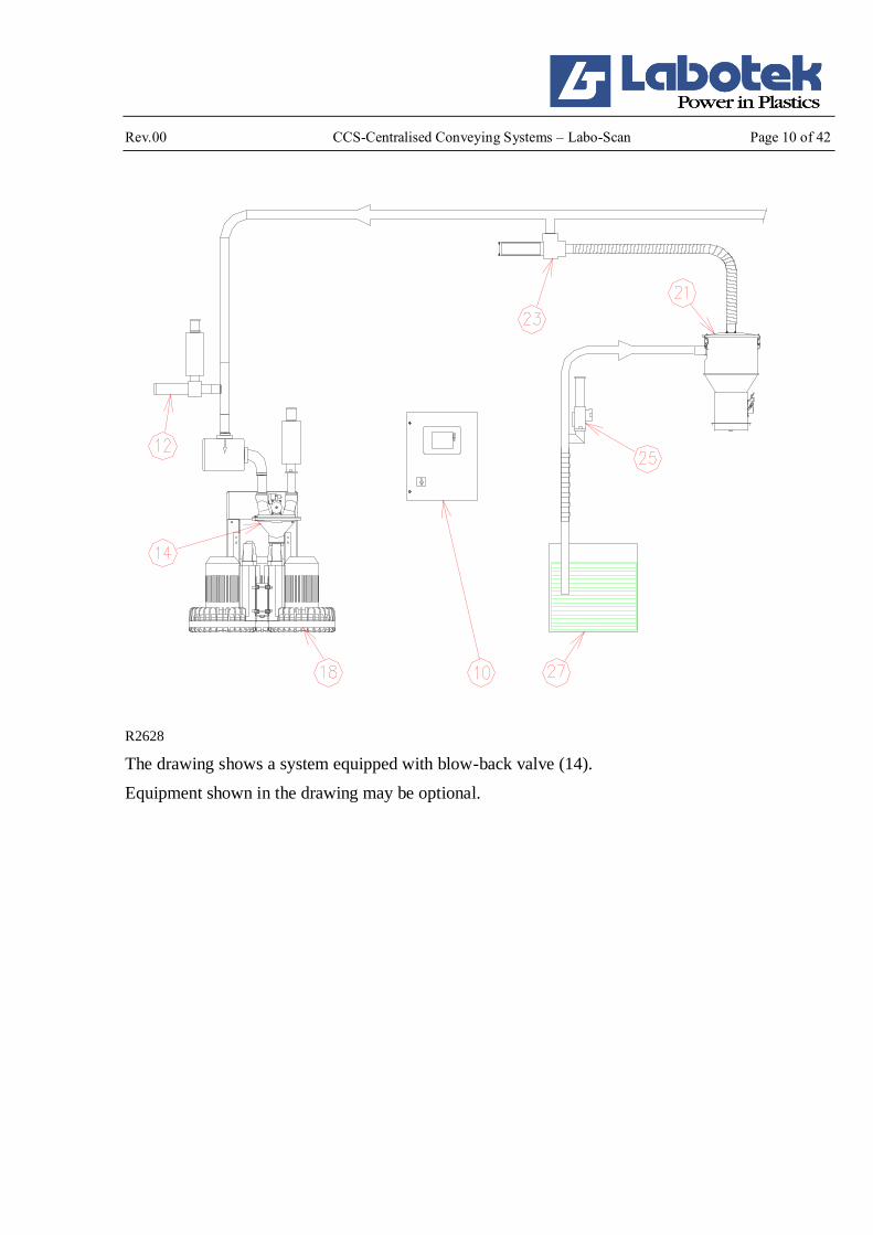
See also section 2.5.4 for the operational sequence of each conveying cycle:
1. When the vacuum receiver (21) is empty the bottom flap, which is also acting as a level
control, will close up against the outlet and by it activating a micro switch. This is registered
in the Labo-Scan control (10) via an electrical signal.
2. Via the bottom flap in the vacuum receiver the system registers all empty vacuum receivers
that are in line for conveying. Each vacuum receiver is activated and filled according to the
principle of first in / first out.
3. The vacuum blower (18) is activated, and the vacuum valve (23) opens in the pre adjusted
time (menu 3.2)
4. A vacuum is generated in the piping system and the raw material (27) is conveyed to the
vacuum receivers according to the time adjusted for each vacuum receiver.
5. When the filling has been completed the line clearing valve (25) opens (if fitted), and air is
admitted into the system via the material suction pipe (menu 3.2). If a slide valve is fitted it
will shut off when the filling has been completed, and by it clearing the piping system.
6. The vacuum valve (23) shuts off and by it vacuum is neutralized in the vacuum receiver (21).
7. The weight of the raw material sucked into the vacuum receiver (21) will cause the bottom
flap to open and the material to fall into the material hopper.
8. When the bottom flap is released against the outlet it automatically indicates to the control,
via the bottom flap switch, that a new conveying cycle will be started only when the level of
the material has dropped sufficiently to allow the bottom flap to close up against the outlet.
9. The Labo-Scan control switches to the next vacuum receiver in the conveying line, and the
conveying cycle is repeated now activating the channel associated to this receiver.
10. When all active vacuum receivers have been filled, the blower will run on for an adjusted time
(20-120 seconds.) (Menu 3.1) keeping the fresh air valve (12) open to avoid overloading the
blower.
The fresh air valve will close according to an adjusted time (menu 3.2) after the blower has
stopped.
Rev.00 CCS-Centralised Conveying Systems – Labo-Scan Page 10 of 42
R2628
The drawing shows a system equipped with blow-back valve (14).
Equipment shown in the drawing may be optional.

Rev.00 CCS-Centralised Conveying Systems – Labo-Scan Page 11 of 42
2.5.4 Sequential diagram
The operational sequences of the components of the system are illustrated in the sequential diagram
below:
R1918_GB

Rev.00 CCS-Centralised Conveying Systems – Labo-Scan Page 12 of 42
2.6 Certificates
2.6.1 IQ-Net Certificate

Rev.00 CCS-Centralised Conveying Systems – Labo-Scan Page 13 of 42
3.0 TECHNICAL DATA
3.1 Type plate
The identification number consists of a code (A), a type number (B) and a serial number (C).
(A) The first and last digit (A) of the code identify the year in which the machine was manufactured. Example: 16 = 2016.
(B) The digits in the middle (B) of the code identify the machine. The type number consists of
two/three digits characterising the machine type:
MSC Labo-Scan Control: 25
(C) The serial number is a four/five-digit number referring to the individual manufacturing
number of the machine.

Rev.00 CCS-Centralised Conveying Systems – Labo-Scan Page 14 of 42
3.2 Dimensioned drawing of vacuum station, example
All dimensions in mm.
R2617
The drawing shows 3xLT6 SVS with blowback-valve and filter.
3.3 Capacity
Labotek’s wide range of vacuum stations, vacuum receivers, piping systems etc. and the modular-designed Labo-Scan control make it possible to meet almost any requirements to capacity and
design.
All systems are customised according to information on capacities, number of processing machines
and conveying distances, and the design will always allow for future extension.

Rev.00 CCS-Centralised Conveying Systems – Labo-Scan Page 15 of 42
4.0 ASSEMBLY
4.1 Fitting the main components
All main components that form part of the system are designed for individual fitting according to
requirements.
4.1.1 Vacuum station
The vacuum station is placed detached. The unit has to be fastened by bolts in the predrilled holes.
The capacity of the vacuum station is calculated on basis of the conveying distances as informed to Labotek; therefore, before altering the machine layout we recommend you to contact Labotek.
To connect the vacuum station follow electrical diagram 202318 placed in the pocket in the back of
the manual.
4.1.2 Labo-Scan control
The Labo-Scan control can be placed either on the wall or in the production area together with other
control units so to make it easily accessible.
To connect the Labo-Scan control follow the electrical diagram placed in the pocket in the back of
the manual.
4.1.3 Vacuum receivers
The vacuum receivers can be fitted either on a machine hopper, a dryer, a mixer or a dosing unit
directly.
4.1.4 Line clearing valve
Filtered, compressed air (5-10 bar (500-1000 kPa)) is to be connected to the connecting branch of
the line clearing valve.
4.1.5 Blow-back valve
Filtered, compressed air (5-10 bar (500-1000 kPa)) is to be connected to the connecting branch of
the blow-back valve.
4.1.6 Slide valve
Filtered, compressed air (5-10 bar (500-1000 kPa)) is to be connected to the connecting branch of
the slide valve.
R1763

Rev.00 CCS-Centralised Conveying Systems – Labo-Scan Page 16 of 42
4.1.7 Central filter, WAM
The central filter is connected to the vacuum station using pipes or hoses.
4.2 Connections
4.2.1 Piping system
Please consider to arrange material pipes and vacuum pipes so to limit the number of bends as much
as possible to ensure minimum loss of vacuum.
4.2.2 Wiring the cables
A four-wire main power cable (3 phases + earth) is connected to the terminal block in the control
cabinet of the vacuum station(s). The internal cable connections interconnecting control cabinet,
vacuum station and blowback valve (if fitted) are performed by Labotek. (See electrical diagram
202318 in the pocket in the back of the manual).
The Labo-Scan control is fitted with single-phase voltage to the terminals. Cables are wired
according to the attached electrical diagram.
4.2.3 The compressed air system
The vacuum valves are fitted on the vacuum pipe, alternatively on top of the vacuum receivers. The
pneumatic controlled valves are connected to a compressed air system supplying filtered and dry
compressed air (5-10 bar (500-1000 kPa).
Compressed air of the required pressure is usually available from the processing machines and
compressed air for the vacuum valves can be supplied from there.
From the compressed air system an air hose is installed to each of the pipe clearing valves and is
connected to the connecting branch.
4.2.4 Central filter, WAM (see also separate manual)
Required supply of compressed air: maximum 10 bars

Rev.00 CCS-Centralised Conveying Systems – Labo-Scan Page 17 of 42
5.0 USERS MANUAL
The system is operated via the TP 177 MICRO touch panel incorporated in the front plate of the control cabinet.
5.1 System setup
To start the setup press “Service menu”. (See fig. below)
Operating the system.
(See point 5.2.1)
Service menu. (See point 5.1.1)
Start / Stop of the
transport system.
To start the system press
”ON”. When the system
has started the button
will be dark shaded.
To stop the system press
”OFF”. When the
system is stopping the
button will be dark shaded.
To transport to each
channel activate this.
(See section 5.2.2)
Status shows which
channel is being transported to including
the channel’s name.
Shows whether conveying has: Started, is Stopping or has
Stopped.
”Started” the conveying system is activated.
“Stopping” the system is shutting down. Conveying to vacuum
receivers that are already in line will be completed ”Stopped” conveying has stopped. There is no transport and no
further channels can be feed.

Rev.00 CCS-Centralised Conveying Systems – Labo-Scan Page 18 of 42
5.1.1 SERVICE MENU
Access to this menu requires a user name and password.
User name: Admin
Password: 1001
Press ECS to return to Main screen.
Press HOME to go to Main screen.
The following need to be setup before using the system points. (See section 5.1.2, 5.1.3, 5.1.4, 5.1.5
and 5.1.6)
Setup of channel name
and type. (See section
5.1.2)
Setup of blowers and
alarm. (See section
5.1.3)
Contrast adjustment up
for the touch panel.
Contrast adjustment down for the touch
panel.
Activate this when
cleaning the panel so no
unwanted adjustments
occur.
Puts the panel into
Transfer mode when
loading new software.
Choose language.
Shows amount of channels and slide
valves of the Labo-Scan system, and
SW version of panel and PLC.
Please notice that the slide valves are
always placed on the first channels.
Calibrates the panel
Alarm list. All alarms will be logged
here so they can be seen later. (See
section 5.3.1)
Adjust date and time.
(See section 5.1.5)
Choice of frequency
converter. (See section
5.1.6)

Rev.00 CCS-Centralised Conveying Systems – Labo-Scan Page 19 of 42
5.1.2 Channel name and type set-up
Press ECS to return to section 5.1.1
Press HOME to return to Main screen.
Forward to the rest of
the pages.
Choose between the
following:
NONE
DH
MACHINE
Touch the field
area”Name” to input the
name. Each channel
must have a unique
name (max. 8 symbols)
and type.

Rev.00 CCS-Centralised Conveying Systems – Labo-Scan Page 20 of 42
5.1.3 Blower and alarm set-up
Press ECS to return to section 5.1.1
Press HOME to go to Main screen.
Setup of run-on time
for blower. (10-120 sec)
(See section 5.1.3.2)
Setup of the cleaning
method. Choose between:
Cyclone.
Central filter.
Blow-back valve. (See section 5.1.3.3)
Setup of the blow-back
time at start and stop. (0-10 sec)
(See section 5.1.3.4)
Setup of frequency
converter speed, if this
option is used. (10-100 %)
(See section 5.1.6)
Setup of delay time for
automatic reset of alarm
lamp.
(20-600 sec)
(See section 5.1.3.1)

Rev.00 CCS-Centralised Conveying Systems – Labo-Scan Page 21 of 42
5.1.3.1 Alarm reset time
When an alarm is activated this timer starts. When time runs out the alarm is deactivated. The alarm
is not confirmed it has to be done manually.
Time can be set from 20 – 600 sec.
5.1.3.2 Run-on time for blower
Used to enter the time the blower is to keep running after a conveying cycle has been completed and
no vacuum receivers are short of material.
The function is created to reduce the number of starting and wear and tear of the blower if a vacuum
receiver becomes short of material just after the blower has stopped. Energy is saved as well.
The optimal run-on time can be adjusted only when the plant has been put into full operation. Due
to different transport distances and number of receivers.
Time can be set from 10 – 120 sec.
5.1.3.3 Cleaning type
Purifying filter, cyclone or blow-back valve.
5.1.3.4 Blowback time at start & stop
Blow-back start indicates blow-back before transport. Blow-back stop indicates blow-back after
transport. (See section 2.5.4)

Rev.00 CCS-Centralised Conveying Systems – Labo-Scan Page 22 of 42
5.1.4 DH and Machine set-up
To set-up transport and pipe cleaning times on DH and Machines are described in section 5.2
Operating the system (See section 5.2.2.1 and section 5.2.3.1)
Rev.00 CCS-Centralised Conveying Systems – Labo-Scan Page 23 of 42
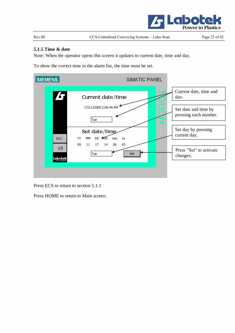
5.1.5 Time & date
Note: When the operator opens this screen it updates to current date, time and day.
To show the correct time in the alarm list, the time must be set.
Press ECS to return to section 5.1.1
Press HOME to return to Main screen.
Current date, time and
day.
Set date and time by
pressing each number.
Set day by pressing
current day.
Press ”Set” to activate
changes.

Rev.00 CCS-Centralised Conveying Systems – Labo-Scan Page 24 of 42
5.1.6 Option
Press ECS to return to section 5.1.1
Press HOME to return to Main screen.
Press here to
choose frequency
converter.

Rev.00 CCS-Centralised Conveying Systems – Labo-Scan Page 25 of 42
5.2 Operating the system
5.2.1 Overview of the various DH / machines
Press ECS to return to Main Screen.
Pages forward to the
various DH / machines.
Name of the DH/machines
Indicates if the
DH/machine is active,
can show:
OFF: Not active
ON: Active
F/F: In queue for transport
Pushing a DH/machine
icon brings you forward
to setup of this particular
DH (See section 5.2.2)/
Machine (See section
5.2.3).

Rev.00 CCS-Centralised Conveying Systems – Labo-Scan Page 26 of 42
5.2.2 Overview of the DH
Press ECS to return to section 5.2.1.
Press HOME to go to Main screen.
Adjustments are not required during normal operation. It may be necessary to adjust the suction probe, and the time of conveying and line clearing when changing to a material of different pellet
size or dust level.
As the operation is fully automatic and no manual attendance is required, only ordinary monitoring
of the operation and functioning of the system are required. Ordinary monitoring includes:
A: Checking the supply voltage and voltage for solenoid valves.
B: Checking the pressure and filters of the compressed-air system.
C: Checking and emptying the central dust/WAM filter daily or at regular intervals according to
requirement. It is recommended to register each time emptying has been carried out.
D: Checking the Labo-Scan control.
Filters (if fitted) in the vacuum receivers are to be checked regularly and cleaned as required, or
replaced if damaged.
Push to activate /
deactivate transport to DH.
Button text shows the
current election, for
example. "ON" that the
chosen transport for this
channel.
Push to adjust transport
time for this DH. (See
section 5.2.2.1)
Bottom flap active.
Transport is active on this DH.
Press here to toggle
between channels.

Rev.00 CCS-Centralised Conveying Systems – Labo-Scan Page 27 of 42
5.2.2.1 Adjustment of DH
Press ECS to return to section 5.2.2
Press HOME to go to Main screen.
Adjusting conveying
time.
Adjusting line clear
time.
Setup of the speed on
the frequency converter
for this DH if option is
used. (20-100%)
Press here to toggle
between channels

Rev.00 CCS-Centralised Conveying Systems – Labo-Scan Page 28 of 42
5.2.3 Overview of machine
Press ECS to return to section 4.2.1
Press HOME to go to Main screen.
Push to activate / deactivate transport to
machine.
Button text shows the
current selection, for
example "ON" that
transport is chosen for
this channel.
Push to adjust transport
time for this machine
(See section 5.2.3.1)
Bottom flap active.
There is no active transport to this
machine.
Press here to toggle
between channels.

Rev.00 CCS-Centralised Conveying Systems – Labo-Scan Page 29 of 42
5.2.3.1 Adjusting the machine
Press ECS to return to section 5.2.3
Press HOME to go to Main screen.
To ensure an optimal throughput all adjustments and test commissioning may be performed prior to
commencement of operations.
The processing machine located farthest off the raw material silo(s) should be adjusted and
commissioned first:
1. Disconnect all vacuum receivers but the one located farthest off (conveying distance).
2. Set the conveying time of this vacuum receiver to 999 seconds and the line clearing time to 0 seconds.
3. Now register the conveying time by observing when the material flow to the vacuum receiver
stops. This occurs when the vacuum receiver has been completely filled.
4. Enter this time in “Conveying Time”.
5. Register the time of line clearing during the next conveying cycle by lifting the suction pipe out of the material and register the time it takes clear out the probe.
6. Enter this time in “Line Clear.
For vacuum receivers equipped with a non-return flap the conveying time must be adjusted so not to
overload the vacuum receiver, as this may hinder the functioning of the non-return flap.
Adjusting the
Conveying time.
Adjusting the Line Clear
time.
Push to select suction
address. (See section 5.2.3.1.1)
Setup of the speed on
the frequency converter
for this Machine if
option is used
(20-100%)
Press here to toggle
between channels.

Rev.00 CCS-Centralised Conveying Systems – Labo-Scan Page 30 of 42
5.2.3.1.1 Overview of the suction addresses
You can select the suction addresses, which are defined as DH container in the configuration of the
channel name. If channels are defined as "machines" or "None", these are not shown because it is
not possible to convey from these. Only channels selected as “DH” allows for slide valves selection.
Press ECS to return to section 5.2.3.1
Press HOME to go to Main screen.
Select suction address.
The sign ”” indicates
the choice of channel.
After selecting address
by pressing the
requested field the
screen returns to the
previous screen.
Forward to the rest of
the pages. (Becomes
visible when more than
7 slide valves.)

Rev.00 CCS-Centralised Conveying Systems – Labo-Scan Page 31 of 42
5.3 Alarms
5.3.1 Alarms:
This control is exclusively associated with transport alarms.
A transport error can occur on all channels. The fault is activated if
transported to a channel 3 times without the bottom flap of the vacuum
receiver remains open due to filled receiver.
Transport error disappears again when the bottom flap of the vacuum
receiver remains open for 20 sec. This means that the receiver is full.
The error also disappears if the channel is turned off (set to OFF).
When an alarm occurs, this icon will appear, and flash as long as there are active alarms.
The number indicates active alarms.
Tap the icon, and a list of active alarms will appear.
(For alarm history, see section 5.3.1)
List of all active alarms.
In the presence of an
alarm, this picture is
displayed in front of the
screen. An active alarm
is indicated with a "C”
after the alarm time (18-
03-2009 10:26:55) and
alarm number (7). The alarm text (Chan. 1
CONVEYING ERROR)
is shown under the time.
By pressing "!" in the
bottom right of the
window, acknowledge
the alarm, and you then
press "CA". If the user
does not acknowledge
the alarm before this has
disappeared, the display will show "CG".
"C" = Come
"A" = Acknowledge
"G" = Gone
It is not possible to
operate the panel until
the alarm window is
closed again. This is
done by pressing the
“X” at the top right corner.
When an alarm occurs, this button will appear.
By pressing the button, the alarm lamp will turn off
and the button disappears again.
The alarm is automatically reset after a given time
(default 60 sec.) By this the button disappears again.
To adjust this see section 5.1..3.

Rev.00 CCS-Centralised Conveying Systems – Labo-Scan Page 32 of 42
5.3.2 Alarm list
Press ECS to return to section 5.2.1.
Press HOME to go to Main screen.
5.3.3 Main switch on vacuum station
The main switch is an ON/OFF switch to START/STOP the vacuum blower. Normally the main
switch should be positioned at ON, as the blower function is controlled by the Labo-Scan control.
5.4 Start
1. IMPORTANT! Check that a filter cartridge is fitted in the filter housing.
2. Check that the voltage available corresponds to the voltage specified on the type plate at the control cabinet of the vacuum station.
3. Check that control signals to the line clearing valve and the vacuum valves are 24 VAC, and
24 VDC to the bottom flaps of the vacuum receivers.
4. Check that the compressed-air supply for valves for vacuum, line clearing and blow-back (if
fitted) is connected to the conveying equipment.
5. Check that the vacuum station is bolted properly.
6. Check that all activated vacuum blowers revolve arrow-directed (in case of reverse rotation,
two phase leads have been switched when connecting the main cable).
7. Check that the central/WAM filter is connected, if fitted.
The alarm list shows
active alarms and alarms
witch has occurred with
time and date.
Alarms coming, alarms
witch are acknowledged and alarms witch
disappears are logged.

Rev.00 CCS-Centralised Conveying Systems – Labo-Scan Page 33 of 42
5.5 Stop
To stop the system press “OFF” on the screen (See section 5.1). Conveying already in line will be completed (status: Stopping).
At status: “stopped” no further conveying will be executed.
Now the system may be disconnected on the main switch.

Rev.00 CCS-Centralised Conveying Systems – Labo-Scan Page 34 of 42
5.6 Screen overview

Rev.00 CCS-Centralised Conveying Systems – Labo-Scan Page 35 of 42
6.0 ACCESSORIES
Customised control units are available according to requirements.

Rev.00 CCS-Centralised Conveying Systems – Labo-Scan Page 36 of 42
7.0 MAINTENANCE
Maintenance is limited to regular control of filters, fuses and contactors for vacuum blowers.
7.1 Maintaining the Labo-Scan control
The Labo-Scan control is checked regularly to ensure that all functioning’s are operative.
Filters, if fitted, in the vacuum receivers should be replaced at least every three months.
7.2 Maintaining the central filter, WAM
See separate manual
Please notice!
When checking or replacing dust filters the scanning system must be shut off.
7.3 Maintaining the vacuum blowers and the valves
Vacuum blowers, line clearing valves and the functioning of the blow-back valve, if fitted, should
be checked once a week. Check the functioning of the compressed-air system including the free
flow of compressed air to-and-from the valves.
At one or more of the following conditions it may be necessary to adjust the stroke speed of the line
clearing valves using the throttle valve:
A: The pressure in the compressed-air system has been changed.
B: Change of material.
C: The system has been modified or extended.
As to dimensioning and calculation of capacity contact the supplier of the system before making
any modifications or extensions.

Rev.00 CCS-Centralised Conveying Systems – Labo-Scan Page 37 of 42
8.0 TROUBLESHOOTING
Malfunctions in the system usually appear by one of the following observations:
- Irregular operation or total stop of the vacuum station.
- Lack of material, wholly or partly, at one or more processing machines.
8.1 Troubleshooting generally
Prior to initiating a comprehensive troubleshooting check the mains supply, the compressed air
system and the raw materials as follows:
1. Power supply:
Connecting fuses
Phase and mains voltage
Thermal relays
Contactors and power switches
Fuses
Cabling
2. Compressed-air:
Compression Flow
Filter
Valves
Pipe joints and pipes
3. Supply of raw material:
Level of raw material in silos, obtains or the like.
Position of telescopic suction probe in raw material.
Pile up of material in the pipes.
8.1.1. Operational malfunctions
Operational malfunctions may be one of the following:
1. The system stops short
2. Conveying of raw material is reduced or stopped to several or all vacuum receivers.
3. Conveying of raw material is reduced or stopped to one vacuum receiver.
Before initiating any troubleshooting activity check that the conveying time, the line clearing time
and the telescopic pipe have been properly adjusted.
Note! At the change of material it may be necessary to readjust the settings if the bulk density and/or
shape of replacement material vary considerably.

Rev.00 CCS-Centralised Conveying Systems – Labo-Scan Page 38 of 42
8.2 The system stops short
Should the system stop short it is usually caused by an electrical error. If the power supply is connected we recommend that you check:
Error Check Remedy
Total stop of the
whole system
The position of the main switch at the Labo-Scan control.
Turn the main switch to position 1.
The position of the main switch at the control cabinet for the
vacuum station
Turn the main switch to position 1.
Control voltage for vacuum station.
Re-establish bad connections, replace defective fuses.
Control voltage 24 VAC for
vacuum station.
Replace fuse, if defective.
Cabling and wiring to the
vacuum station
Re-establish bad connections, replace
defective cables and wires.
Control voltage for the Labo-
Scan control.
Re-establish defective
connections/defective fuses replace
according to diagram
Fuses. Replace defective fuses, if any.
Important!
When defective fuses are replaced the cause of error should always be
established and remedied accordingly.

Rev.00 CCS-Centralised Conveying Systems – Labo-Scan Page 39 of 42
8.3 Reduced or stopped conveying of raw material to several or all vacuum
receivers
Error Check Remedy
Conveying reduced
or stopped to several
or all the vacuum
receivers.
Level of raw material in silo, octabin, bag or like.
Supply new/more material
Position of telescopic pipe in silo,
octabin or bag.
Adjust position and e.g. telescopic
suction probe by dislocating inner
and outer pipe proportionally
Line clearing valves
Do the valves close tight? Remove any impurity between valve seat and piston.
Have the piston gaskets become leaky?
Replace the piston gaskets.
Has the return spring become slackly or has it gone?
Replace the return spring
Do the piston and the piston rod work sluggishly?
Replace piston/piston rod
Condition of filter at cylinder
cover?
Replace or clean filter as required.
The mechanical functioning of
the solenoid valve of the line
clearing valve?
Replace the solenoid valve if it flaps.
The supply of compressed air to
the solenoid valve?
Repair any leaks. Clean filter and
check compressed-air system. Adjust
pressure and flow.
The vacuum valve does not pick
up the electric signal connections.
(24 VAC) from the control.
Re-establish wires and Replace the
fuse.
No or reduced
conveying in general.
Check the blow-back valve if
fitted
Repair the blow-back valve (see list
of spare parts.)
Check control signal (24 VAC) for coil at the relay
Replace fuse according supplementary to diagram. Replace
vacuum valve.
Check the mechanical functioning of fresh air valve
Repair fresh air valve. (see list of spare parts).
Control signal 24 VAC for coil at solenoid valve of fresh air valve
Replace fuse in the system. Replace vacuum valve
Conveying capacity
reduced
One or more of the non- return
flaps are open or worn
Check functioning of non-return
flaps, if fitted. Check adjustment of
conveying time (the vacuum receiver must not be filled to overflowing).
Replace defective non-return flaps.

Rev.00 CCS-Centralised Conveying Systems – Labo-Scan Page 40 of 42
8.4 Reduced or stopped conveying of raw material to some of the vacuum
receivers
Adjust conveying time of the individual vacuum receivers in accordance with conveying distances
and capacity of the hopper making sure that material is not able to pile up in the piping system.
At reduced conveying to one processing machine first check that the conveying time, the telescopic
suction pipe and the line clearing valve have been correctly adjusted. Then check as follows:
Error Check Remedy
Conveying to one
vacuum receiver has
stopped
Whether the vacuum receiver has been activated in the Labo-Scan control
Activate the vacuum receiver in question at the TP 177
MICRO panel.
The disc filters in top of the vacuum receiver (fitted only if the system is
supplied with blow-back valve).
Clean or replace filter as required.
Central, self-purifying filter, if fitted Replace cartridge filter and empty dust collector.
Leakiness between vacuum receiver and filter on side of the vacuum receiver
Clean the contact surfaces and replace the filter.
The bottom flap of the vacuum receiver
(its closing mechanism and the micro switch).
Adjust or repair the bottom
flap as required
The spring controlled bottom flap must
close up properly when conveying to the associated vacuum receiver.
A “click” must sound from the micro
switch when the bottom flap is
approximately half-open.
Replace a defective micro
switch.
Leaks in the vacuum receiver, the piping system and the vacuum piping system.
Repair hopper and/or piping systems.
The mechanical functioning of the vacuum valve which is fitted on top of
the vacuum receiver
Clean off any impurity at the vacuum valve which may
cause leaks or hinder a free
and unobstructed movement of
the piston or the piston rod.
Replace gaskets.
Replace vacuum valve.
Control signal (24 VAC) to the supplementary relay for vacuum blower.
Replace fuse Replace vacuum valve
In case a malfunction in a channel cannot be located or remedied immediately the vacuum receiver in question can be transferred electrically via the Labo-Scan control to an available channel, if any,
until spare parts can be procured.

Rev.00 CCS-Centralised Conveying Systems – Labo-Scan Page 41 of 42
9.0 REPAIRS
9.1 Replacing the bottom flap vacuum receiver PGT
1. Clear the vacuum receiver.
2. Disconnect the vacuum receiver by pressing OFF at the TP 177 MICRO operator panel.
3. Unplug the vacuum receiver to disconnect the power supply.
4. Dismantle the vacuum receiver from the processing machine.
5. Turn the machine upside down or sideways and remove the bottom flap by removing screw
and disc (66).
6. Remove dust and impurity from the mounting cylinder (67).
7. Fit the bottom flap (51) on the maundering cylinder (67).
Adjust the bottom flap by dislocating it in the oval hole so that the discharge branch is
covered completely.
At vacuum receivers Scanning PGT 4 the bottom flap is to be located as near to the edge as possible.
At vacuum receivers Scanning PGT 61 and PGT 9 the bottom flap is to be pushed back
completely.
8. Adjust the spring function of the bottom flap, if necessary. See separate manual
9. Mount the vacuum receiver on the processing machine and plug in the vacuum receiver to reconnect the power supply.
10. Connect the vacuum receiver by pressing ON at the TP 177 MICRO operator panel.
R1512

Rev.00 CCS-Centralised Conveying Systems – Labo-Scan Page 42 of 42
9.2 Replacing the bottom flap vacuum receiver SVR (stainless)
1. Clear the vacuum receiver.
2. Disconnect the vacuum receiver by pressing OFF at the TP 177 MICRO operator panel.
3. Unplug the vacuum receiver to disconnect the power supply.
4. Dismantle the vacuum receiver from the processing machine.
5. Turn the machine upside down or sideways and remove the bottom flap by removing the split pin (77).
6. Remove the magnet (79) and the balance weight (78) from the bottom flap.
7. Fit the magnet (79) and the balance weight (78) at the bottom flap.
8. Remove dust and other impurity from the mounting fixture.
9. Fit the bottom flap (51) in the mounting fixture using the split pin (77).
10. Adjust the proximity switch if necessary. See separate manual
11. Fit the vacuum receiver on the processing machine and plug in the vacuum receiver to
reconnect the power supply.
12. Turn on the vacuum receiver by pressing ON at the TP 177 MICRO operator panel.
R1979
1 2
3 4
5
### ###
### ###
###
F1 F2
F3 F4
F5