cd-player appendices - ralph toman - · pdf filesee also chapter 1.5.4, "mechanical...
TRANSCRIPT

Table of contents
Part 1
Description
CD-Player Appendices
Repair instructions for most CD-players
English
Internet:e-mail:
Author: Ralph Toman http://www.ralph-toman.de [email protected]
www.ralph-toman.de Repair CD-Player
Status: 08.15.2005 II
Table of Content
1 Description ......................................................................................... 1-1 1.1 Introduction......................................................................................... 1-1 1.2 Copyright, Exclusion of Damages (Liability) ....................................... 1-1 1.2.1 Copyright ............................................................................................ 1-1 1.2.2 Exclusion of Damages (Liability) ........................................................ 1-1 1.3 Safety instructions .............................................................................. 1-2 1.4 Rules for working with electrostatic sensitive components or
modules.............................................................................................. 1-2 1.5 Repair instruction ............................................................................... 1-3 1.5.1 Cleaning the lens................................................................................ 1-5 1.5.2 Increasing the laser current ................................................................ 1-7 1.5.3 Alignment of the CD-player .............................................................. 1-10 1.5.4 Mechanical alignment....................................................................... 1-15
www.ralph-toman.de Repair CD-Player
Status: 08.15.2005 III
List of illustrations
Fig. 1-1: Cover of laser-pickup................................................................................. 1-5
Fig. 1-2: Pick-up laser.............................................................................................. 1-6
Fig. 1-3: Measuring junctions on a Technics CD-player .......................................... 1-7
Fig. 1-4: Oscillogram of HF (EFM)........................................................................... 1-8
Fig. 1-5: Pick Up with potentiometer in a Pioneer CD-player................................... 1-9
Fig. 1-6: Printed circuit board of a Technics CD-player ......................................... 1-10
Fig. 1-7: Test CD ................................................................................................... 1-11
Fig. 1-8: Square-wave signal on measuring junction "Focus Offset" ..................... 1-12
Fig. 1-9: Pushbutton for the Service Mode ............................................................ 1-14
www.ralph-toman.de Repair CD-Player
Status: 08.15.2005 IV
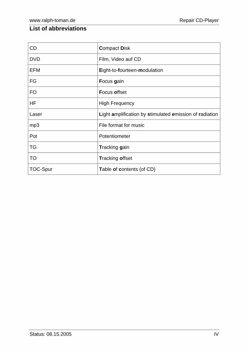
List of abbreviations
CD Compact Disk
DVD Film, Video auf CD
EFM Eight-to-fourteen-modulation
FG Focus gain
FO Focus offset
HF High Frequency
Laser Light amplification by stimulated emission of radiation
mp3 File format for music
Pot Potentiometer
TG Tracking gain
TO Tracking offset
TOC-Spur Table of contents (of CD)
www.ralph-toman.de Repair CD-Player
Status: 08.15.2005 V
List of appendices
Laser Classes.......................................................................................................... A-1 Addresses................................................................................................................ A-2

www.ralph-toman.de Repair CD-Player
Status: 08.15.2005 1-1
1 Description
1.1 Introduction Repairing CD-players is hardly worth nowadays as labor in craft is quite expensive and you can get a new player at a very low price. One example: A CD-player approx. 5 years old doesn’t play the CDs any more. The costs estimate amounts to approx. 30 Euro. The repair costs, however, can increase up to 100 Euro. In this case, I would say repair isn’t worthwhile since you can buy a new player for about 49 Euro (as a special offer). These players do even play Mp3 files and DVDs. Furthermore, a new player is covered by guarantee. This instruction shall help to repair CD-players which are not worth to be repaired through specialist shops.
1.2 Copyright, Exclusion of Damages (Liability)
1.2.1 Copyright All texts and graphics of this document are protected by copyright if not indicated differently. It is also not allowed to print extracts of the text. If you want to publish this instruction on your website please send an email to [email protected]. I will then decide whether this instruction may be published on the respective site.
1.2.2 Exclusion of Damages (Liability) In no event shall I be liable for any damage whatsoever (including, but not limited to, damages for personal injury) arising out of the application of this instruction. Protection measures are strictly to be observed. High voltages exist in CD-players and if you come into contact with them it could be life-threatening. During repair activities safety regulations have to be observed in order to avoid damage caused by short circuit, electric shock or fire. The author does not assume the liability for consequential damages to persons and/ or any kind of equipment or the accuracy and completeness of the data.

www.ralph-toman.de Repair CD-Player
Status: 08.15.2005 1-2
1.3 Safety instructions Meaning of warnings and notifications in this operating manual: CAUTION Disregard can lead to seriously injuring the operator
and to equipment damage.
ATTENTION Disregard can lead to malfunctions and damaging the equipment.
NOTE Important additional information
1.4 Rules for working with electrostatic sensitive components or modules
All electronic modules are equipped with highly integrated chips or components. The engineering of these electronic components makes them extremely sensitive to over voltages and thus sensitive to static electricity discharges as well. The acronym ESD, or electrostatic sensitive device, is used to describe such components. Electrostatic sensitive modules are identified by this symbol:
ATTENTION Electronic components and modules must always be protected against electric charging and discharging. For this reason, the following measures must be observed for components or modules that are being tested or installed.
Electrostatic sensitive components or modules must not get in contact with materials which are chargeable (including all standard types of plastic). Any person not conductively linked to the ambient electrical potential can be electrostatic charged. Rules for working with electrostatic sensitive components or modules:
• Ensure that persons, the work area, and packaging have proper grounding when working with electrostatic sensitive modules. This avoids static charging.
• Avoid any contact with electrostatic sensitive modules unless it is inevitable (e.g. for maintenance). Handle the modules in such a manner, that contact with either the component pins or strip
www.ralph-toman.de Repair CD-Player
Status: 08.15.2005 1-3
conductors are avoided. This will prevent discharge energy from reaching and damaging sensitive components. If you must carry out measurements on a module, ensure to discharge yourself before performing the tasks. To do so, touch grounded metallic objects. Use grounded measuring devices only.
• The components must remain in their packaging until they are actually needed.
• Once it has been disassembled, a defective module must be placed in its original packaging.
• The converter must be switched off before modules are assembled or disassembled.
• Neither test voltage nor signals must be applied to the modules until the device has been switched on.
1.5 Repair instruction You’ve loaded a CD into your CD-player, but the player doesn’t play it. What can you do? Those of you owning a 2-channel oscilloscope (or those who can borrow one) can try to get the CD-player started quite easily. But even without an oscilloscope you can take remedial action - e.g., if you follow the chapters 1.5.1 and 1.5.2 mentioned below. The following should be said to alcohol: isopropyl alcohol can be bought at the chemist’s where it is very cheap. Ethyl alcohol would be an alternative; it is comparable, but much more expensive. Ethyl alcohol is drinkable, isopropyl alcohol is not. A certain substance makes it undrinkable. It’s the same with methylated spirit. For our purposes, the cheap alcohol will do. Isopropyl alcohol will leave a white thin coating on the surface of the lens after it is evaporated. This is the substance mentioned above. However, it is no problem; you can simply use the dry end of a cotton bud to wipe it off. The lens will be clean then. Another problem can occur: The disk drive doesn’t rotate at all. In such a case the motor can be faulty (actually this is seldom the case) or the focusing doesn’t function any more. The latter can easily be checked: Hold a CD quite near the lens and check if the lens moves up and down. If this is the case the CD-player tries to find the optimum focusing, i.e., focusing functions correctly. Mostly, the following 3 reasons are responsible for the main defects:
Laser (lens) is dirty Laser is not strong enough The device needs to be readjusted
If you have checked or cleared these 3 error sources and the CD-player still doesn’t function, certainly, the laser must be replaced. This, however, isn’t worth if the player cost about 100 Euro. In the following, I will explain step by step how you can try to get the CD-player started and work properly.
www.ralph-toman.de Repair CD-Player
Status: 08.15.2005 1-4
Basically: If you change the position of the potentiometers, mark the original position before. I also like to turn the potentiometers but if, e.g., I turn more than 1 potentiometer I often forget the original position of each of them: one potentiometer adjusted incorrectly can disable the entire CD-player. You need the following material:
Cotton buds (ear swabs) Isopropyl alcohol Screwdriver (for recessed-head screws) Small screwdriver (for slotted screws) One 2-channel oscilloscope for the alignment
The following error symptoms can occur:
The CD-player doesn’t recognize the loaded CD The CD-player recognizes the CD, but doesn’t play it The CD-player doesn’t play all songs The CD jumps while it is played

www.ralph-toman.de Repair CD-Player
Status: 08.15.2005 1-5
1.5.1 Cleaning the lens First of all you have to remove the cover of the casing to clean the laser lens. You might have to remove the hplastic part above the laser to reveal the lens. This part is mostly fixed with plastic catches and may be connected with a spring. The following figure shows a Pioneer CD-player. The plastic part (1) has to be removed using the two plastic catches (2). Take a small screwdriver and push the catches to the left. At the same time, slightly lift the plastic part (1).
Fig. 1-1: Cover of laser-pickup
www.ralph-toman.de Repair CD-Player
Status: 08.15.2005 1-6
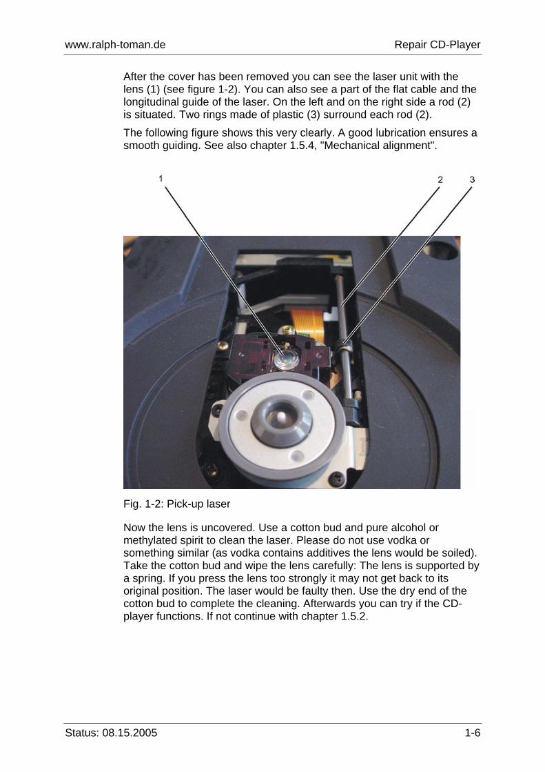
After the cover has been removed you can see the laser unit with the lens (1) (see figure 1-2). You can also see a part of the flat cable and the longitudinal guide of the laser. On the left and on the right side a rod (2) is situated. Two rings made of plastic (3) surround each rod (2). The following figure shows this very clearly. A good lubrication ensures a smooth guiding. See also chapter 1.5.4, "Mechanical alignment".
Fig. 1-2: Pick-up laser
Now the lens is uncovered. Use a cotton bud and pure alcohol or methylated spirit to clean the laser. Please do not use vodka or something similar (as vodka contains additives the lens would be soiled). Take the cotton bud and wipe the lens carefully: The lens is supported by a spring. If you press the lens too strongly it may not get back to its original position. The laser would be faulty then. Use the dry end of the cotton bud to complete the cleaning. Afterwards you can try if the CD-player functions. If not continue with chapter 1.5.2.

www.ralph-toman.de Repair CD-Player
Status: 08.15.2005 1-7
1.5.2 Increasing the laser current The laser current has to be increased. Depending on the type of the CD-player the measuring points are on the big printed circuit board. Sometimes the measuring points are pins. In the case of the Sony CD-player the measuring points are jumpers with a big splodge of solder in the middle. Other CD-players do not have something similar. The measuring point "HF" or "EFM" must be looked for. This is not easy in some cases because some devices do not have points at all. The following figure shows a Technics CD-player. The measuring points are jumpers/wire straps. Jumper no. 1 is the "GND", jumper no. 2 has the signal "EFM" and jumper no. 3 is the jumper where you can measure the signal "Focus Offset".
Fig. 1-3: Measuring junctions on a Technics CD-player
www.ralph-toman.de Repair CD-Player
Status: 08.15.2005 1-8
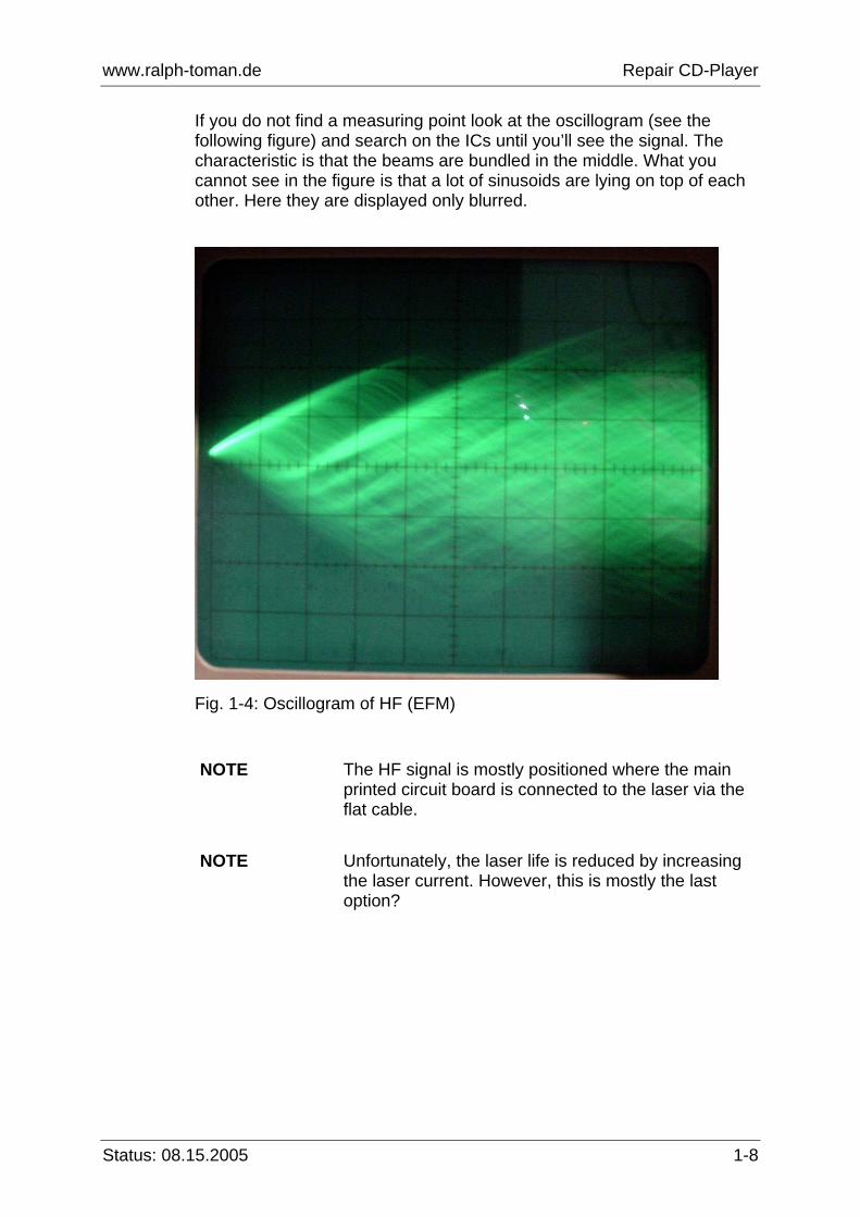
If you do not find a measuring point look at the oscillogram (see the following figure) and search on the ICs until you’ll see the signal. The characteristic is that the beams are bundled in the middle. What you cannot see in the figure is that a lot of sinusoids are lying on top of each other. Here they are displayed only blurred.
Fig. 1-4: Oscillogram of HF (EFM)
NOTE The HF signal is mostly positioned where the main
printed circuit board is connected to the laser via the flat cable.
NOTE Unfortunately, the laser life is reduced by increasing the laser current. However, this is mostly the last option?

www.ralph-toman.de Repair CD-Player
Status: 08.15.2005 1-9
As soon as you have found the signal increase the laser current. The appropriate potentiometer (1) is positioned either directly on the laser or on the flat cable connecting the laser unit with the big printed circuit board. The following figure shows the potentiometer clearly.
Fig. 1-5: Pick Up with potentiometer in a Pioneer CD-player
After you have found the potentiometer turn it very carefully! and, simultaneously, observe the HF-signal. ATTENTION If you turn up the potentiometer too quickly the laser
might get too much current and the laser diode will break. Therefore turn it only slightly observing the oscillogram. Potentiometers are often sealed with lacquer. Turning the potentiometer can cause an uncontrolled jerk.
The amplitude must increase. In most cases this is sufficient. If the potentiometer has already reached its limit stop then this is quite suspect. Even if the CD-player is functioning now you can assume that it won’t last long. A potentiometer at its limit stop is never good. If this procedure

www.ralph-toman.de Repair CD-Player
Status: 08.15.2005 1-10
hasn’t helped to get the CD-player working an alignment is necessary (see the following chapter).
1.5.3 Alignment of the CD-player Principally, there are two different types of CD-players. The older versions have got potentiometers on their printed circuit board. The following figure shows the printed circuit board of a Technics CD-player.
Fig. 1-6: Printed circuit board of a Technics CD-player
You can clearly see the yellow potentiometers (1, 2 and 3) which are used for the alignment. On newer CD-players the alignment is done automatically. So, if your CD-player is a modern one, you cannot in fact do much. I assume that you have got a device with all the following potentiometers:

www.ralph-toman.de Repair CD-Player
Status: 08.15.2005 1-11
TG (Tracking Gain) TO (Tracking Offset) TB (Tracking Balance) (isn’t always available!) FG (Focus Gain) PDB (Best eye) (in Technics devices!)
Furthermore, we need a test CD and a black gum tape approx. 0.9 mm broad and impervious to light. This must be adhered to the bright side of the CD. NOTE The tape must not pass through the middle of the CD.
Otherwise the CD might not be recognized [the information is in the inner edge of the CD (TOC-track)].
The following figure shows a test CD.
Fig. 1-7: Test CD
After the CD has been prepared as described before, insert it into the CD player. The potentiometer positions/adjustments are marked. What’s
www.ralph-toman.de Repair CD-Player
Status: 08.15.2005 1-12
important now is if the CD player can read the CD at least. If no reading is possible this alignment cannot take place. The entire laser could be defective. In order to check this, get all potentiometers into center position. Then take the CD from the drawer and check with the naked eye if a red beam can be seen in the laser. The laser beam is a dark red point and you should see it on the surface of the lens if you look onto the lens slanting your head. CAUTION Do not look directly or for a prolonged time into the
laser beam, just glance at it. The laser is very weak but can, however, cause health damages. See also laser classes in the appendix.
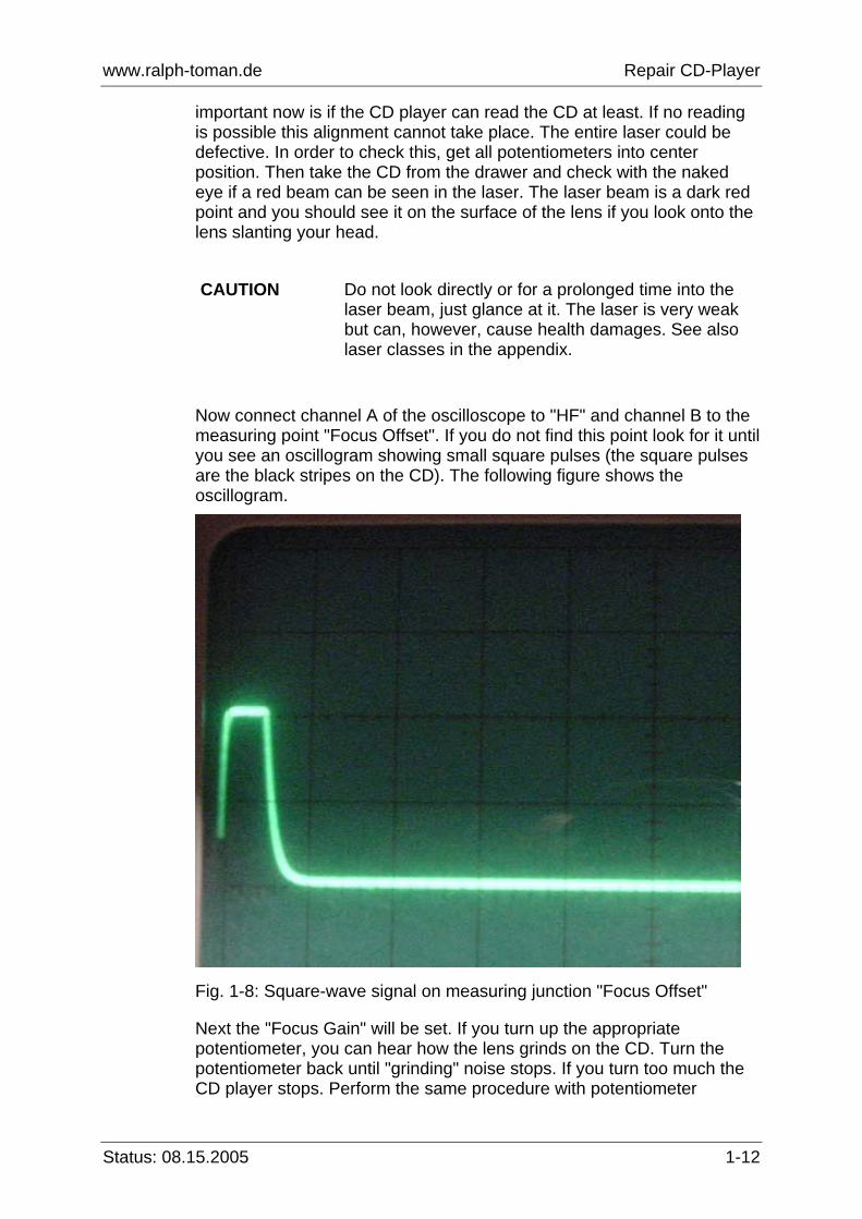
Now connect channel A of the oscilloscope to "HF" and channel B to the measuring point "Focus Offset". If you do not find this point look for it until you see an oscillogram showing small square pulses (the square pulses are the black stripes on the CD). The following figure shows the oscillogram.
Fig. 1-8: Square-wave signal on measuring junction "Focus Offset"
Next the "Focus Gain" will be set. If you turn up the appropriate potentiometer, you can hear how the lens grinds on the CD. Turn the potentiometer back until "grinding" noise stops. If you turn too much the CD player stops. Perform the same procedure with potentiometer

www.ralph-toman.de Repair CD-Player
Status: 08.15.2005 1-13
"Tracking Gain" and afterwards with potentiometer "Focus Offset". HF dropouts should now be visible. There must not be any time shifting. Perform this procedure with potentiometer "Tracking Offset". If your CD-player has got the potentiometers "PDB" and "E-F-Balance", set them so that the HF looks as clear as possible, i.e., shows as little film as possible. If the CD-player doesn’t function yet repeat this alignment or reset one of the potentiometers. You can assume that 80 % of the CD-players will function after the instructions mentioned above have been followed. If your player is one of the remaining 20 %, it is uncertain if a new laser unit is worth to purchase. In fact, I cannot claim that the player doesn’t function only because of the faulty laser. If the player is still faulty I would suggest to take it to a specialist shop or to someone else who knows a lot about CD-players. A further test is described in paragraph 1.5.4. This paragraph deals with the mechanical alignment. Just a comment to the electrical alignment: The service manuals often describe how to activate the service mode. Sometimes this mode is quite helpful: you can check the laser without inserting a CD. The service mode of a Pioneer CD-player is activated as follows:
www.ralph-toman.de Repair CD-Player
Status: 08.15.2005 1-14
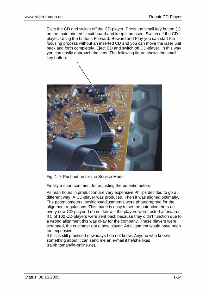
Eject the CD and switch off the CD-player. Press the small key button (1) on the main printed circuit board and keep it pressed. Switch off the CD-player. Using the buttons Forward, Reward and Play you can start the focusing process without an inserted CD and you can move the laser unit back and forth completely. Eject CD and switch off CD-player. In this way you can easily approach the lens. The following figure shows the small key button:
Fig. 1-9: Pushbutton for the Service Mode
Finally a short comment for adjusting the potentiometers: As man hours in production are very expensive Philips decided to go a different way. A CD-player was produced. Then it was aligned optimally. The potentiometers‘ positions/adjustments were photographed for the alignment regulations. This made is easy to set the potentiometers on every new CD-player. I do not know if the players were tested afterwards. If 5 of 100 CD-players were sent back because they didn’t function due to a wrong alignment this was okay for the company. These players were scrapped, the customer got a new player. An alignment would have been too expensive. If this is still practiced nowadays I do not know. Anyone who knows something about it can send me an e-mail if he/she likes ([email protected]).

www.ralph-toman.de Repair CD-Player
Status: 08.15.2005 1-15
1.5.4 Mechanical alignment In the previous sections we assumed that the mechanics wasn’t misadjusted and a mechanically perfect CD was inserted into the Disc tray. Another reason for the CD player not functioning properly is an unbalanced CD or a slightly misadjusted mechanics. Unfortunately, the mechanical alignment cannot be described generally for all CD players. Anyone who wants to perform a mechanical alignment must order the service manual for his/her CD player. However, not every service manual describes a mechanical alignment. It might be better to contact the manufacturer to get information if there is a description available at all. It is worth asking since the prices for a service manual can amount to 30 Euro. See the appendix for addresses of companies that offer schematic diagram. If an unbalanced CD has been inserted it must be replaced by a perfect one. If you use an oscilloscope to look at the HF you will see the amplitude pumping (voltage height). This pumping must be reduced to a minimum. In order to function perfectly the mechanics has to be greased. The laser is moved over the whole area via two rods that are mounted sideways it. The laser is powered by spindle that is driven by a motor. Those rods and the spindle are greased. If the is not enough grease or it resinified new grease has to be used for re-greasing. A good brand for greasing is „Ballistol“. Simply use an ear swab for putting some grease on the rods and make sure the motor moves the laser from one side to the other, and this way spreads the grease consistently. This might happen by putting a 80 min CD into the player.

www.ralph-toman.de Repair CD-Player
Status: 08.15.2005 A-1
Laser Classes Depending on the potential endangerment through the accessible radiation laser units are divided into classes: 1, 2, 3A, 3B and 4 (1, 1M, 2, 2M, 3R, 3B and 4). Class 1 Class I laser products produce no accessible laser emissions. For example, a CD player or DVD player/recorder contains an internal laser to read or write data, but does not actually emit any laser light. Products of this type are Class I laser systems. Class I lasers products present no hazard at all unless they are disassembled to gain access to the internal components. Class 2 Class II laser products can emit up to 1 milliwatt (1/1000th watt) of accessible laser emissions. Low powered laser pointers, data and telecommunications gear, and some scientific systems use lasers of this output classification. Class II laser products are not capable of causing permanent eye injuries, but can still be quite hazardous due to glare and temporary flash blindness. . Class 3A Class IIIa laser products can emit up to 5 milliwatts (5/1000th watt) of accessible laser emissions. The most common laser pointers, and all inexpensive laser display systems fall into this output classification. Class IIIa lasers pose an eye hazard with prolonged exposure, and should not be directed towards the eyes or face, and should never directed into or out of a moving vehicle. Class 3B Class IIIb laser products can emit up to 500 milliwatts (½ watt) of accessible laser emissions. Some scientific and medical systems, and low powered laser display systems may be classified into this category. Class IIIb lasers are capable of causing a permanent eye injury with brief exposure, can cause minor skin burns, and can ignite many materials with sustained or focused exposure. Class 4 Class IV laser products emit any amount of power greater than 500 milliwatts (1/2 watt). Industrial laser systems, research, scientific, and medical lasers, and the largest laser display systems are Class IV laser products. Class IV lasers can cause permanent eye injury before you can react, can cause serious skin burns, and can quickly ignite flammable materials at a considerable distance.
www.ralph-toman.de Repair CD-Player
Status: 08.15.2005 A-2
Addresses Schaltungsdienst Lange Zehrensdorfer Str. 11 12277 Berlin Tel.: 030/ 723 81-3 Fax.: 030/ 723 81-500 http://www.schaltungsdienst.de Schaltplandienst München Inh. Robert Martyson Greinerberg 10 81371 München Tel.: 089/ 157 80 771 Fax.:089/ 157 80 772 http://www.schaltplan-dienst.de