cd - sce 132 conduit entrances to pull boxes cd 132.1 conduit entrances to pull boxes cd 133 corner...
TRANSCRIPT

ConduitsTable of Contents
SCE Public
Approved by:
UGSSheet
Underground Structures Standards
Effective Date: i
04-29-2016
CD
ConduitsTable of Contents
Standard Title
CD 100 Conduit Installation Standards
CD 100.1 Conduit Installation Standards
CD 101 Conduit Bank and Terminal Requirements
CD 101.1 Conduit Bank and Terminal Requirements
CD 110 Conduits and Fittings
CD 110.1 Conduits
CD 110.2 Fittings
CD 111 ”Y” Fittings
CD 111.1 ”Y” Fittings
CD 112 Instructions for Solvent Welding and Installation of Semi-Rigid Plastic Conduit and Fittings
CD 112.1 Instructions for Solvent Welding and Installation of Semi-Rigid Plastic Conduit and Fittings
CD 115 Manufacturer’s Requirements
CD 115.1 Approved Manufacturers for Plastic Conduit
CD 115.2 Requirements for Semi-Rigid PVC Plastic Conduit
CD 115.3 Manufacturer’s Minimum Inspection and Testing Requirements for Semi-Rigid PVC EB/DB Conduits
CD 120 Conduit Bank Requirements
CD 120.1 Conduit Bank Requirements
CD 120.2 Residential Conduit Bank Requirements
CD 120.3 Conduit Bank Requirements for CIC
CD 121 Conduit Bank Requirements – Installation in a Bore
CD 121.1 Conduit Bank Requirements – Installation in a Bore
CD 121.2 Conduit Spacers
CD 122 Conduit Beam Reinforcement
CD 122.1 Conduit Beam Reinforcement
CD 125 Directional Boring Installation Standards

ConduitsTable of Contents
Approved by:
UGSSCE Public
Underground Structures Standards
Effective Date:ii
04-29-2016
CDSheet
Standard Title
CD 125.1 Directional Boring Installation Standards
CD 130 Standard Conduit Entrance Details
CD 130.1 Standard Conduit Entrance Details
CD 131 Standard and Special Conduit Entrances
CD 131.1 Standard and Special Conduit Entrances
CD 132 Conduit Entrances to Pull Boxes
CD 132.1 Conduit Entrances to Pull Boxes
CD 133 Corner Conduit Entrance Details — Manhole or Vault
CD 133.1 Corner Conduit Entrance Details — Manhole or Vault
CD 134 Conduit Terminators
CD 134.1 Conduit Terminators
CD 135 Typical Installation of Precast Pull Box in Main Line Conduit
CD 135.1 Typical Installation of Precast Pull Box in Main Line Conduit
CD 140 Standard Conduit Location for Precast Vaults and Manholes 6' x 12' and Larger
CD 140.1 Standard Conduit Location for Precast Vaults and Manholes 6' x 12' and Larger
CD 141 Conduit Recess Layout — Precast Concrete Vaults — 7' x 10', 8' x 10', and Larger
CD 141.1 Conduit Terminators
CD 142 Conduit Terminators for Precast Tunnel Vaults
CD 142.1 Conduit Terminators for Precast Tunnel Vaults
CD 144 Conduit Bank Entrance to Power Cable Trench Where Trench Extension is Planned
CD 144.1 Conduit Bank Entrance to Power Cable Trench Where Trench Extension is Planned
CD 146 Intercepting Existing Conduit Runs
CD 146.1 Intercepting Existing Conduit Runs
CD 148 Capping Main Line Conduit
CD 148.1 Capping Main Line Conduit
CD 150 Service Lateral Terminations
CD 150.1 Service Lateral Terminations
ConduitsTable of Contents
SCE Public
Approved by:
UGSSheet
Underground Structures Standards
Effective Date: iii
04-29-2016
CD
Standard Title
CD 160 Pole Riser Bend Standard Location
CD 160.1 Pole Riser Bend Standard Location
CD 161 Pole Riser Bend for Risers on Kicker Blocks
CD 161.1 Pole Riser Bend for Risers on Kicker Blocks
CD 162 Neutral Wire Riser Installation for Four-Wire Systems
CD 162.1 Neutral Riser Wire Installation for Four-Wire Systems
CD 163 Communication Conduit and Riser Bend Installation
CD 163.1 Communication Conduit and Riser Bend Installation
CD 164 Specification for Abandoning Conduit and Risers
CD 164.1 Specification for Abandoning Conduit and Risers
CD 166 Three-, Four-, Five-, or Six-Inch Fiberglass Riser Bends
CD 166.1 Three-, Four-, Five-, or Six-Inch Fiberglass Riser Bends
CD 170 Riser Bend Installation at Wall or Pad
CD 170.1 Riser Bend Installation at Wall or Pad
CD 172 Underground Risers in Substation
CD 172.1 Underground Risers in Substation
CD 175 Streetlight Conduit and Riser Bend Installation for Service to One Streetlight Standard
CD 175.1 Typical Conduit and Riser Bend Installation for Service to One Streetlight Standard
CD 175.2 Typical Conduit and Riser Bend Installation for Handhole through Service to Streetlight Standards
CD 175.3 Typical Conduit and Riser Bend Installation Loop through Service to Streetlight Standards
CD 177 Riser Conduit Lower Terminal (Anchor for Cable Support)
CD 177.1 Riser Conduit Lower Terminal (Anchor for Cable Support)
CD 180 Blank Conduit Plugs for Vaults, Manholes, and PME and PMH Structures
CD 180.1 Blank Conduit Plugs
CD 180.2 Conduit Plug and Riser Cap
CD 190 Supports for Conduits on Bridges
CD 190.1 Exterior Supports — General Fabrication and Installation Guide
ConduitsTable of Contents
Approved by:
UGSSCE Public
Underground Structures Standards
Effective Date:iv
04-29-2016
CDSheet
Standard Title
CD 191 Expansion Joint for Plastic Conduit
CD 191.1 Expansion Joint for Plastic Conduit
CD 192 Expansion Joint for HDG Conduit on Bridges
CD 192.1 Expansion Joint for HDG Conduit on Bridges
CD 197 Conduit Mandrels — Type I and Type III
CD 197.1 Conduit Mandrels — Type I and Type III

Conduit Installation Standards
SCE Public
Approved by:
UGSSheet
Underground Structures Standards
Effective Date: 1 of 9
10-23-2015
CD 100
CD 100 Conduit Installation Standards
Scope CD 100.1 Conduit Installation Standards
The following standards cover the methods to be used in performing the work essential to the installation of conduit for the Southern California Edison Company. Reference to Company herein will be interpreted as the Southern California Edison Company, and reference to Contractor will be interpreted as the organization or party performing the specified construction.
1.0 Conduit
1.1 Conduit will consist of one of the types specified in CD 110 or a Company approved equal. In known water or subsidence areas, semi-rigid plastic conduit will be used.
1.2 All rigid conduit will be carefully aligned and laid to a uniform grade as specified on the plan or profile of working drawings. A slight degree of snaking will be permitted with flexible and semirigid plastic conduit.
1.3 A minimum conduit coverage of 30 inches will be maintained unless otherwise specified.
1.4 When conduit is located in streets drained by gutters, cover is to be determined from flow line of gutter.
1.5 No conduit will be installed that is cracked, damaged, or contains any roughness that would injure the cable jacket.
1.6 All questionable conduit to be installed will be tested for passage of mandrel prior to installation. Any conduit not permitting passage of mandrel will be rejected.
1.7 All conduit banks requiring concrete encasement will be adequately held in place to prevent floating during installation. Edison inspectors will approve conduit construction prior to placing concrete.
1.8 General
A. All joints on semirigid plastic and rigid PVC conduits will be made with solvent cement in accordance with manufacturer’s recommendations and CD 112. A watertight seal is required at all joints.
B. When directional boring, a locking watertight joint may be used and does not require solvent cement. Joint will be made per manufacturing installation instructions.
C. Conduit supplier is to provide up-to-date joining instructions with conduit delivery.
D. Edison inspector is to verify type and date of solvent cement prior to application of semirigid plastic and rigid PVC conduit.
2.0 Conduit Entrances, Terminations, and Connections
2.1 Conduit will be terminated in substructures as follows:
A. Flush with face of recesses including reduced conduit sizes with cast in terminators, CD 142;
What’s Changed?

Conduit Installation Standards
Approved by:
UGSSCE Public
Underground Structures Standards
Effective Date:2 of 9
10-23-2015
CD 100Sheet
B. With end bells if terminated other than in a recess CD 134 (Exception: Floorless structures.);
C. End bells may be omitted on conduit connecting substructures less than 10 feet apart.
2.2 Metal conduit will be terminated in substructures with galvanized conduit bushings unless otherwise specified.
2.3 Care must be taken to maintain roundness of conduit at terminations.
2.4 Grout conduit at outside wall. Encase per CD 112.
2.5 Edison inspector is to be present during installation of all conduit entrances and terminations.
2.6 All terminations will be in end walls of structures. Side wall terminations and core drilling are not permitted except where no alternative exists and with SCE approval.
3.0 Excavation
3.1 Excavation will be fully protected against hazard to the public and will be braced to prevent caving. Proper protective measures will be used where excessive caving is encountered or where protection is required for adjacent structures or roads. The requirements of the California State Construction Safety Orders and OSHA will be complied with.
3.2 The Company reserves the right to specify when protective measures for excavation must be employed.
3.3 Contractor will provide walkways and/or roadways around and over excavations to safely accommodate traffic, both along streets and into adjacent buildings. Such structures will conform with existing local regulations.
3.4 Trench subgrades will be brought to a uniform grade. Subgrade of spongy, unstable, or other unsuitable material will be removed and replaced with suitable bedding material.
3.5 Where rocks are encountered during excavation, they will be removed to 0.6 inches below the trench bottom and the conduit structure laid on a bed of compacted sand.
3.6 Special care will be taken to prevent damage to existing buried structures and facilities. Contractors will assume responsibility for proper notification and restitution to interested parties in the event of damage to existing structures.
4.0 Buried Neutral Wire, Bond Wire, and Ground Wire
4.1 Neutral wire is required in conduit banks as specified in DDS-2.
4.2 Any ground wire required will be supplied by the contractor.
4.3 On joint construction with telephone, a bond wire may be required between telephone and Edison substructures. (Consult working drawings.) Install bond wire in conduit bank, bring through recess, and attach to grounding bar at substructure floor.
What’s Changed?

Conduit Installation Standards
SCE Public
Approved by:
UGSSheet
Underground Structures Standards
Effective Date: 3 of 9
10-23-2015
CD 100
4.4 Telephone company to furnish No. 6 solid-tinned copper-bond wire and clamp when required.
5.0 Mechanical Protection
5.1 Concrete encasement or semi-encasement, as specified, is required on all rigid and semirigid conduit (except Hot Dip Galvanized [HDG] and schedule 80 PVC). Encasement will be per CD 120. DB-type conduit with no encasement may be installed only where specified on the working drawings. Extreme care must be taken to prevent conduit collapse when installing DB and EB type conduit.
5.2 Conduits
A. Full concrete encasement, when specified, will have a minimum concrete coverage of three inches on top, bottom, and sides of the conduit.
B. Concrete semi-encasement, when specified, will have a minimum of concrete coverage of three inches on top and sides of the conduit.
5.3 No concrete cap or encasement of any type will be poured without prior notice to the Company Inspector.
5.4 Concrete for conduit bank protection may have the following minimum proportions:
A. Water content sufficient to give a minimum slump of two inches and maximum of four inches;
B. Aggregate content of a maximum of 40 percent sand by weight and a coarse aggregate of 3/8-inch maximum size;
C. Cement content will be a minimum of 190 pounds per cubic yard.;
D. Compaction may be by any suitable means that assures elimination of voids and does not damage the conduit;
E. Water reducing admixture ASTMC494 Type A will be used to increase the workability of the concrete. Admixtures with calcium chloride are not acceptable. Admixtures will be applied per manufacturer recommendations.;
F. Artificial color is not required.
6.0 Backfill
6.1 Conduit Bedding
A. Bedding will be defined as that material supporting, surrounding, and extending to one foot (305 mm) above the facility.
What’s Changed?

Conduit Installation Standards
Approved by:
UGSSCE Public
Underground Structures Standards
Effective Date:4 of 9
10-23-2015
CD 100Sheet
B. Where mechanical protection is not used, bedding material will be clean sand, pea gravel, or native free-draining granular material having a sand equivalent of not less than 30 or having a coefficient of permeability greater than 1.4 inches/hour.1/ Clean sand may be jetted where permitted.
C. Where concrete protection of conduit is used, six inches of well-dampened earth will be placed over concrete protection in the trench two hours after the concrete is poured. Backfilling of the trench excavation may then be completed.
D. Conduit bedding will meet the requirements of Section 5.0 (Sheet 3).
6.2 Backfill — General
A. Backfill will be considered as starting one foot (305 mm) above the pipe or conduit, or at the top of concrete bedding over the pipe or conduit. All material below this point will be considered bedding.
B. All backfill will be placed as specified in Section 6.3 (Sheet 4) and compaction requirements will be in accordance with Section 6.4 (Sheet 5).
C. Rocks greater than six inches (152 mm) in any dimension will not be permitted in backfill placed between one foot (305 mm) above the top of any pipe or conduit and one foot (305 mm) below pavement subgrade.
D. Rocks greater than two and one-half inches (64 mm) in any dimension will not be permitted in backfill placed within one foot (305 mm) of the pavement subgrade.
E. The native material obtained from project excavations may be used as backfill provided that all organic material, rubbish, debris, and other objectionable material are first removed. Backfill soil will be approved by the governing agency.
6.3 Mechanically Compacted Backfill2/
A. Backfill will be mechanically compacted by means of tamping rollers, vibrating rollers, stompers (impact-type pavement breakers), wackers, or other hand-held mechanical tampers.
B. Prior to mechanically compacting backfill, determine proper moisture content of soil. Optimum moisture in all soil types is desirable for obtaining required compaction.
C. Material for mechanically compacted backfill will be placed in horizontal layers of thickness or lifts, which, prior to compaction, will not exceed the thickness specified below for the various types of equipment.
1. Hand-directed mechanical tampers and walk-behind vibratory plates — maximum uncompacted lift thickness of four inches (102 mm).
1/ Standard Specifications for Public Works Construction, 1997 Edition (Greenbook), Subsection 306-1.2.12/ Greenbook, Section 306-1.3
What’s Changed?

Conduit Installation Standards
SCE Public
Approved by:
UGSSheet
Underground Structures Standards
Effective Date: 5 of 9
10-23-2015
CD 100
2. Rolling equipment, including sheepsfoot (both vibratory and nonvibratory), grid, smooth-wheel (nonvibratory), pneumatic-tired and segmented wheels — maximum uncompacted lift thickness of one foot (305 mm).
3. Impact, free-fall, or stomping equipment — maximum uncompacted lift thickness of three feet (914 mm).
D. Mechanically compacted backfill will be moistened or dried as necessary to obtain optimum moisture level (plus or minus two percent). Each layer will be evenly spread and compacted until the specified relative compaction has been attained.
E. Method of measuring relative compaction and any test requirements will be in accordance with agency permit requirements.
6.4 Backfill Compaction Requirements3/
Backfill will be densified to the following minimum relative compaction. See Figure CD 100–1 (Sheet 8).
A. 85% Relative Compaction:
1. Between subgrade and the upper three feet (914 mm), measured from the pavement surface (or finished grade where there is no pavement);
2. Outside the traveled roadway, shoulders, and other paved areas;
3. Under sidewalks.
B. 90% Relative Compaction:
1. In upper three feet (914 millimeters), measured from the pavement surface (or finished grade where there is no pavement), within the existing or future traveled roadway, shoulders, and other paved areas (or areas to receive pavement);
2. Within engineered embankments;
3. Where lateral support for existing or proposed structures.
C. 95% Relative Compaction:
1. Within State Highways;
2. Where pavement is placed directly on the compacted backfill, the top six inches (152 mm) immediately under the pavement will meet this requirement.4/
3/ Greenbook, Subsection 306-1.3.44/ Greenbook, Subsection 301-1.3
What’s Changed?

Conduit Installation Standards
Approved by:
UGSSCE Public
Underground Structures Standards
Effective Date:6 of 9
10-23-2015
CD 100Sheet
6.5 Sand Slurry Backfill
All trenches 10 inches or less in width and other trenches when directed by SCE or as required by agency permit and as required elsewhere in this specification will be backfilled using sand slurry with a minimum one sack per cubic yard of cement.5/ California Department of Transportation jobs requiring sand slurry backfill will have minimum 1-1/2 sacks per cubic yard of cement.
6.6 Base
A. Base material will be reconstructed to the same dimensions (thickness, and so forth) and with the same or equivalent materials used in the original work.
B. Where the original thickness is six inches (152 mm) or less, the base material may be compacted in one layer. Where the original thickness is more than six inches (152 mm), the base material will be compacted in two or more lifts of approximately equal thickness and the maximum compacted thickness of any one layer will not exceed six inches (152 mm).
C. The relative compaction of each layer of compacted base material will not be less than 95 percent.6/
7.0 Pavement Resurfacing
7.1 Temporary Resurfacing7/
A. Unless permanent pavement is placed immediately, temporary pavement will be placed immediately after backfilling. Temporary bituminous resurfacing two inches (51 mm) thick will be placed and maintained wherever excavation is made through pavement or driveways. In sidewalk areas, the temporary resurfacing will be at least one inch (25 mm) thick; in all other areas it will be at least two inches (51 mm) thick. At major intersections and other critical locations a greater thickness may be required.
B. Placement of permanent resurfacing will be performed within two weeks after the placement of temporary resurfacing unless otherwise specified by the governing civil agency.
7.2 Permanent Resurfacing — General8/
All surface pavement damaged or removed as a result of the excavation work will be reconstructed to the same dimensions, except for pavement thickness below, and with the same type material used in the original work. Resurfacing will be one inch (25 mm) greater in thickness than existing pavement.
5/ Greenbook, Mix 100-E-100 per Substation 201-1.1.26/ Greenbook, Subsection 301-2.37/ Greenbook, Subsection 306-1.5.18/ Greenbook, Subsection 302-5.6.2, 306-1.5.2
What’s Changed?

Conduit Installation Standards
SCE Public
Approved by:
UGSSheet
Underground Structures Standards
Effective Date: 7 of 9
10-23-2015
CD 100
7.3 Asphalt Pavement
A. Edges of the surface surrounding a patch repair must be free of water, foreign material, or dust. The prepared edges should be tack coated to ensure a bond between them and the patch material. Enough time should be allowed for the emulsion to “break” and most of the water to dry out before the patch-mix is placed.
B. Asphalt pavement will be compacted to a density of 95 percent. To ensure a good surface seal along the cut (joint) line, a four-inch (102 mm) wide band of emulsion will be applied over the joint at the surface level, covered with a light coating of sand.
C. Upon completion, the pavement will be true to grade and cross section. When a ten-foot (3.05 m) straightedge is laid on the finished surface parallel to the centerline of the excavation, the surface will not vary from the edge of the straightedge more than 1/8" (3.17 mm).
7.4 Concrete Pavement
A. Concrete will be reconstructed with the same type of material used in the original work or approved substitute. Concrete will be placed on a subgrade sufficiently dampened to ensure that no moisture will be absorbed from the fresh concrete.
B. Immediately after being mixed, the concrete will be deposited on the subgrade to the required depth over the entire width of the section.
C. The concrete surface will be finished true to grade and cross section. Upon completion, the surface will be free of any unevenness greater than 1/8" (3.17 mm) when checked with a ten-foot (3.05 m) straightedge placed on the surface of the pavement.9/
9/ Greenbook, Subsection 302-6.4.1
What’s Changed?

Conduit Installation Standards
Approved by:
UGSSCE Public
Underground Structures Standards
Effective Date:8 of 9
10-23-2015
CD 100Sheet
Figure CD 100–1: Backfill Minimum Relative Compaction
Note(s): 1. Upper three-foot zone — backfill material will be minimum 90% relative compaction, per Section 6.4 (Sheet 5).2. Below 3' to utility — backfill material will be minumum 85% relative compaction, per Section 6.4 (Sheet 5).3. The overall cover (depth), utility clearances, and construction are governed by the California Public Utilities Commission.
8.0 Mandrelling, Cleaning, and Pullrope Installation
8.1 All mandrelling must be done in the presence of the Company Inspector.
8.2 A mandrel will be pulled through each conduit upon completion of the duct bank and compaction of the trench backfill.
8.3 The mandrel must be sized to the smallest inside conduit diameter for a straight or riser conduit run.
8.4 All cement, sand, and foreign matter will be removed. If obstructions are found that cannot be removed by cleaners so as to pass the specified mandrel, the conduit will be removed and relaid at the Contractor’s expense.
8.5 Conduits will have a minimum of 3/8-inch diameter polypropylene pull rope, with a minimum breaking strength of 3,000 pounds (GI 040). The pull rope will be left in each conduit. Another option besides the use of ropes for conduits smaller than 4 inches is pull tape approximately 3/4" wide with a 2,500 lb tensile breaking strength. (See GI 040.) A three-foot length of rope or tape will be left projecting from the conduit at each substructure, and securely tied there. Where the approved conduit plug is used (CD 180), the rope or tape will be securely tied to it.
8.6 All pull rope and pull tape will be new. Used ropes and tapes are not acceptable.
See Note 3.
3'See Note 1.
See Note 2.
Pavement95% Compaction
Base (if existing) ortop 6" of backfill,95% compaction
Bedding
Utility
What’s Changed? Secton 8.5 was modified to change minimum pull rope diameter to be 3/8-inch. Added clarification to Figure CD 100-1.

Conduit Installation Standards
SCE Public
Approved by:
UGSSheet
Underground Structures Standards
Effective Date: 9 of 9
10-23-2015
CD 100
9.0 Railroad Crossings
9.1 All conduit within railroad rights-of-way must have a minimum of four feet of cover from bottom of rail.
9.2 When specified on the working drawing, the following is required:
A. HDG conduit (or steel casing) when under the rail bed;
B. Full concrete encasement (CD 120) on conduit not under the rail bed;
C. Installation of marker signs (furnished by Edison) at designated locations;
D. Installation of a marker tape (Alarmoline, Cat. No. AL-6100-YE) directly above conduit, one foot below grade. (Supplier: Maydwell & Hartzell, Inc., 6400 Corvette Street, Los Angeles, CA 90040.)
What’s Changed?

This page intentionally left blank.

Conduit Bank and Terminal Requirements
SCE Public
Approved by:
UGSSheet
Underground Structures Standards
Effective Date: 1 of 1
01-26-2007
CD 101
CD 101 Conduit Bank and Terminal Requirements
Scope CD 101.1 Conduit Bank and Terminal Requirements
Each conduit installation will be in conformance with the requirements set forth in the drawings, specifications, schedules, and tabulations referred to below.
1. Concrete in accordance with CD 100
2. Concrete envelope, complete or partial, in accordance with CD 120
3. Conduit material in accordance with CD 110
4. Conduit entrance into underground structure to be in accordance with CD 100, CD 130, CD 131, CD 132, and CD 133
5. Conduit stub-outs in main line trench in accordance with CD 148
6. Service lateral stub-outs in accordance with CD 150
7. Riser end of riser conduits in accordance with CD 161, CD 160, CD 162, CD 163, CD 170, or CD 172
8. Vault, manhole, and pull box terminals of pole riser conduits in accordance with CD 177, when so noted on working drawings
9. Conduit alignment in accordance with CD 100
10. Conduit depth in accordance with CD 100
What’s Changed?

This page intentionally left blank.
Conduits and Fittings
SCE Public
Approved by:
UGSSheet
Underground Structures Standards
Effective Date: 1 of 3
01-26-2007
CD 110
CD 110 Conduits and Fittings
Scope CD 110.1 Conduits
1.0 Conduits
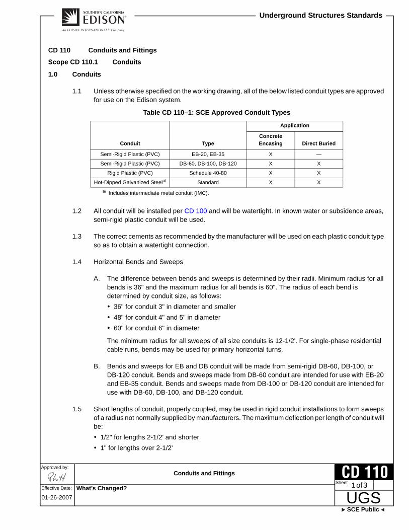
1.1 Unless otherwise specified on the working drawing, all of the below listed conduit types are approved for use on the Edison system.
Table CD 110–1: SCE Approved Conduit Types
1.2 All conduit will be installed per CD 100 and will be watertight. In known water or subsidence areas, semi-rigid plastic conduit will be used.
1.3 The correct cements as recommended by the manufacturer will be used on each plastic conduit type so as to obtain a watertight connection.
1.4 Horizontal Bends and Sweeps
A. The difference between bends and sweeps is determined by their radii. Minimum radius for all bends is 36" and the maximum radius for all bends is 60". The radius of each bend is determined by conduit size, as follows:
36" for conduit 3" in diameter and smaller
48" for conduit 4" and 5" in diameter
60" for conduit 6" in diameter
The minimum radius for all sweeps of all size conduits is 12-1/2'. For single-phase residential cable runs, bends may be used for primary horizontal turns.
B. Bends and sweeps for EB and DB conduit will be made from semi-rigid DB-60, DB-100, or DB-120 conduit. Bends and sweeps made from DB-60 conduit are intended for use with EB-20 and EB-35 conduit. Bends and sweeps made from DB-100 or DB-120 conduit are intended for use with DB-60, DB-100, and DB-120 conduit.
1.5 Short lengths of conduit, properly coupled, may be used in rigid conduit installations to form sweeps of a radius not normally supplied by manufacturers. The maximum deflection per length of conduit will be:
1/2" for lengths 2-1/2' and shorter
1" for lengths over 2-1/2'
Conduit Type
Application
Concrete Encasing Direct Buried
Semi-Rigid Plastic (PVC) EB-20, EB-35 X —
Semi-Rigid Plastic (PVC) DB-60, DB-100, DB-120 X X
Rigid Plastic (PVC) Schedule 40-80 X X
Hot-Dipped Galvanized Steela/
a/ Includes intermediate metal conduit (IMC).
Standard X X
What’s Changed?

Conduits and Fittings
Approved by:
UGSSCE Public
Underground Structures Standards
Effective Date:2 of 3
01-26-2007
CD 110Sheet
1.6 All plastic (PVC) conduit must be manufactured by an Edison approved manufacturer (see CD 115) and comply to Edison requirements.
1.7 EB-20 semi-rigid PVC conduit is preferred and should be utilized for standard installations requiring encasement. EB-35 PVC conduit can be installed in lieu of EB-20 conduit at the contractor’s discretion.
1.8 For direct buried installations, DB-60 conduit may be used for all sizes smaller than four inches. DB-100 or DB-120 conduit is required when four-, five-, or six-inch conduit is installed.
What’s Changed?

Conduits and Fittings
SCE Public
Approved by:
UGSSheet
Underground Structures Standards
Effective Date: 3 of 3
01-26-2007
CD 110
Scope CD 110.2 Fittings
1.0 Fittings
1.1 All couplings, adapters, segments, end bells, and so forth will be standard types recommended by the manufacturer or a Company-approved equal.
1.2 The couplings, sweeps, and other fittings are to be made of the same material as the conduit.
1.3 Offset couplings are not approved.
1.4 The spigot end of all fittings (segments, sweeps, bends, and so forth) will be chamfered at 45° ± 15° on the inside surface in order to make a smooth transition when installed into EB and DB conduit.
1.5 Name or trademark of fitting manufacturer will be placed on the outside surface of all fittings with 1/4" minimum size letters.
What’s Changed?

This page intentionally left blank.

”Y” Fittings
SCE Public
Approved by:
UGSSheet
Underground Structures Standards
Effective Date: 1 of 2
01-26-2007
CD 111
CD 111 ”Y” Fittings
Scope CD 111.1 ”Y” Fittings
Figure CD 111–1: ”Y” Fittings
“Y” fittings are available in two types — the one-piece “Y” (for new installations) and the split “Y” (for existing installations). Install “Y” fittings only when called out on the working drawing.
Figure CD 111–2: ”Y” Fittings — Installation Example
1.0 New Installations
When installing one-piece “Y” fittings, mandrel all conduits and install approved pull ropes or pull tapes in conduit from “1” to “2.”
6" MINStraight
R = 5'-0"MIN
30ºMAX
1
2
3
ac
Pole
When Req’d CapSee Note 5.
Installation Example
See Note 3.Additional 12-1/2' Rsegments may berequired here onnew construction
“Y” Fitting (DB Type Conduit)
Method 1
b
Method 2
All notes on Method 1typical for Method 2.
“Y” Fitting Stacked
See Note 3.
1
2
3
ac
b
What’s Changed?

”Y” Fittings
Approved by:
UGSSCE Public
Underground Structures Standards
Effective Date:2 of 2
01-26-2007
CD 111Sheet
2.0 Existing Installations
When installing split “Y” fittings, carefully remove existing conduit (see Notes) from “a” to “b.” Tie approved pull rope to cables at “c” and extend to “3.” Place split “Y” around cables, cement couplings to existing conduits and tape “Y” sides with duct tape. Encase in concrete for watertightness. Pull tape may not be used if it is tied to a pull rope or another length of pull tape.
Note(s): 1. Notify division office prior to working on or near Edison conduits containing energized cables.2. “Method 1” or “Method 2” will be called out on working drawings.3. See CD 160 and CD 161 for pole riser bend locations.4. Approved Manufacturers: Armorcast Products, Carlton Products Corp., Vimar, Inc., R. W. Johnson, Inc.5. Per CD 148.
What’s Changed?

Instructions for Solvent Welding and Installation of Semi-Rigid Plastic Conduit and Fittings
SCE Public
Approved by:
UGSSheet
Underground Structures Standards
Effective Date: 1 of 2
10-24-2014
CD 112
CD 112 Instructions for Solvent Welding and Installation of Semi-Rigid Plastic Conduit and Fittings
Scope CD 112.1 Instructions for Solvent Welding and Installation of Semi-Rigid Plastic Conduit and Fittings
All plastic conduit and fittings to be joined should be exposed to the same temperature conditions for a reasonable length of time before assembly.
1.0 Solvent Welding
Make certain that all foreign matter has been wiped from both the conduit and fitting (at joint). The conduit should not be inserted over halfway into the fitting to make a good interference solvent weld. Inspect cement container for proper check date. Cement over 12 months old should not be used. PVC solvent cement (SAP 10064261) and (SAP 10064150) for a pint and quart, respectively) shall only be used to make a PVC-PVC connection, while ABS-PVC solvent cement (SAP 10064107) and (SAP 10064108), P and QT) shall be used to make an ABS-PVC connection. For inspecting purposes, the ABS-PVC solvent cement is turquoise in color. A primer (SAP 10063037) and (SAP 10113448), P and QT) must be used for both applications per the manufacturer's instructions. The primer can be used for both PVC-PVC and ABS-PVC connections but shall only be applied to the PVC (see manufacturer's instructions).
Apply a liberal and uniform coat of cement to the mating zone of the fitting and conduit. It must be emphasized that most joint failures are caused by dry joints where an insufficient coating of solvent cement is applied, or when solvent cement has evaporated due to high temperature conditions. Work fast! Slip conduit straight into the fitting with a slight twist until it bottoms. Hold the joint for 15 seconds (one minute in extreme cold weather) so that the conduit does not push out of the fitting. Do not twist or drive pipe after insertion is complete. The joined members will be cured for five minutes or more before they are handled. (In cold or damp weather, this interval should be increased to allow for the slower evaporation of the solvent.) Minimum trench widths may be utilized by assembling conduit above ground (allowing for weld cure period) and lowering the preassembled conduit bank into the trench.
Be sure to wipe off the excess solvent that is left on the outer shoulder of the fitting. Care should be exercised to prevent excess solvent from being forced into the fitting at the inside shoulder of the conduit. Plastic bristle brushes should not be used. (The solvent will dissolve the bristles.) A large brush should be used with the maximum size permitted to be the width of the fitting socket.
Cans of solvent should be kept covered and away from excess heat and flames when not in use. Quart cans are generally the largest practical size to use since the solvent dries rapidly. Use only solvent cement as furnished or recommended by the conduit manufacturer. Solvent cement thinner may not be used for thinning cement which has thickened.
2.0 Cutting Conduit
Use a hacksaw to cut conduit that is less than two inches in diameter. The conduit must be cut straight and cleaned of burrs.
3.0 Bends and Sweeps
In cases where a joint is made with the union under stress due to misalignment, bends, or other factors, the joint must be held rigid in such a manner as to relieve the stress on the joint until the conduit is backfilled or encased.
4.0 General Conduit Bank Requirements
For general information and conduit bank requirements, see CD 100 and CD 120.
What’s Changed? SAP Numbers added.

Instructions for Solvent Welding and Installation of Semi-Rigid Plastic Conduit and Fittings
Approved by:
UGSSCE Public
Underground Structures Standards
Effective Date:2 of 2
10-24-2014
CD 112Sheet
5.0 Expansion and Contraction
Due to conduit bank requirements of plastic conduit (1-1/2 inches per 100 feet for every 20°F change in temperature), the following precautions should be taken:
1. Allow extra conduit lengths at each tie-in for contraction and expansion.
2. Backfill from center of trench both ways or from one tie-in point toward the other end of the trench.
3. Conduit may be cut to correct length for tie-in after backfill is complete and contraction (or expansion) has stabilized. All conduit tie-ins entering manhole, vault, or pull box walls will be grouted into place and concrete encased for a distance of 12 to 15 inches outside the walls.
6.0 Handling
To minimize accidental mechanical damage, conduit should not be left exposed in an open trench longer than is absolutely necessary. In transporting long lengths of conduit, provision should be made to support the full length to avoid damage due to excess overhang.
Conduit that is to be stored in excess of two weeks prior to installation will be protected from the sun. Protection may consist of tarps or other opaque coverings.
Conduits will not be stocked in excess of 42 inches for storage if storage is to exceed two weeks’ duration.
7.0 Inspection
All plastic conduit will be tested by the Southern California Edison Company. Underground inspectors will pick up random samples (five-foot lengths) of conduit from Edison jobs. Conduit found to be defective will not be acceptable per CD 110.
What’s Changed?

Manufacturer’s Requirements
SCE Public
Approved by:
UGSSheet
Underground Structures Standards
Effective Date: 1 of 4
10-23-2015
CD 115
CD 115 Manufacturer’s Requirements
Scope CD 115.1 Approved Manufacturers for Plastic Conduit
Listed below are the approved manufacturers of plastic conduit and fittings acceptable for use on the Edison system.
1.0 Rigid PVC Conduit
1.1 Approved manufacturers of rigid (Sch. 40 and Sch. 80) PVC conduit, as purchased under Edison Material Standard No. 215 are:
A. Cantex Inc.
B. Prime Conduit
C. JM Manufacturing
D. Heritage Plastics
1.2 Approved manufacturers of fittings for this conduit are:
A. Armorcast
B. Cantex Inc.
C. Prime Conduit
D. Kraloy
E. JM Manufacturing
F. Cal Am Manufacturing
G. Heritage Plastics
2.0 Semi-Rigid PVC Conduit
2.1 All sizes of EB-20, EB-35, DB-60, DB-100, and DB-120 will conform to ASTM F512-89a
What’s Changed? Section 1.2 updated for clarity.

Manufacturer’s Requirements
Approved by:
UGSSCE Public
Underground Structures Standards
Effective Date:2 of 4
10-23-2015
CD 115Sheet
2.2 Approved manufacturers of these underground semi-rigid PVC conduits are:
A. Cantex Inc1/
B. Prime Conduit
C. JM Manufacturing
D. Heritage Plastics
2.3 Approved manufacturers of fittings for this conduit are:
A. Cantex Inc.
B. Prime Conduit
C. JM Manufacturing
D. Heritage Plastics
2.4 Approved fabricators of underground rigid and semi-rigid PVC conduits and fittings are:
A. SAF-T-CO Supply Inc.
B. TVC Communications
1/ Approved with 500,000 psi PVC material EB-20, EB-35, DB-60, DB-100, and DB-120.
What’s Changed? Section 2.4 was added for approved fabricators of underground rigid and semi-rigid PVC conduits.

Manufacturer’s Requirements
SCE Public
Approved by:
UGSSheet
Underground Structures Standards
Effective Date: 3 of 4
10-23-2015
CD 115
Scope CD 115.2 Requirements for Semi-Rigid PVC Plastic Conduit
1.0 General
1.1 EB-20 and EB-35 (concrete encased burial) conduit will be manufactured in conformance to ASTM F512-89a.
1.2 DB-60, DB-100, and DB-120 (direct burial without concrete encasement) conduit will be manufactured in conformance to ASTM F512-89a.
1.3 Reworked PVC materials will conform to the requirements of ASTM F512-89a, Section 5.2 and in addition are limited to a maximum of 15%.
2.0 Conduit Color
All semi-rigid PVC conduit will be gray in color.
3.0 Conduit Marking
3.1 All conduit will be clearly marked with the manufacturer’s name, PVC cell classification, size, type of conduit, the manufacturer’s minimum wall thickness, code or control number, actual manufacture date, and the designation “ASTM F512” at intervals of 1.5 meters (5 feet) or less. Any additional markings deemed necessary by the manufacturer is permitted.
Example: (MFG’s NAME) PVC 12254-A-4" DB 100 MIN. WALL 140 (MFG’s CONTROL NO.) (MFG. DATE/CODE) ASTM F512 (The marking sequence may vary.)
3.2 Semi-rigid PVC conduit from 2-inch through 6-inch sizes will have a circumferential mark placed on the spigot end of each conduit length, per the dimensions and requirements of Section 12.5 of ASTM F512-89a.
4.0 Quality Control
4.1 Approved semi-rigid PVC plastic conduit manufacturers will establish and maintain an inspection and testing program per the requirements of Scope CD 115.3 (Sheet 4). The program will be submitted to the Customer Service Department Engineering section of the Southern California Edison Company for approval. Manufacturers who fail to establish and maintain an SCE-approved Quality Control Program cannot furnish PVC conduit to any SCE projects.
What’s Changed?

Manufacturer’s Requirements
Approved by:
UGSSCE Public
Underground Structures Standards
Effective Date:4 of 4
10-23-2015
CD 115Sheet
Scope CD 115.3 Manufacturer’s Minimum Inspection and Testing Requirements for Semi-Rigid PVC EB/DB Conduits
1.0 Dimensional Inspections and Frequencies
1.1 Spigot End
A. Wall thickness — one every two hours, each line
B. Outside diameter — one every two hours, each line
C. Out of round — one every two hours, each line
D. Chamfer and marking (visual) — one every two hours, each line
1.2 Bell End
A. Entrance diameter — one every two hours, each line
B. Bottom diameter — one every two hours, each line
C. Socket depth — one every two hours, each line
D. Out of round — one every two hours, each line
E. Bell centered (visual) — one every two hours, each line
2.0 Testing Requirements
2.1 Physical Tests and Frequencies
A. Conduit stiffness — one test within the first two hours of each shift, each line
B. Conduit impact resistance — one test within the first two hours of each shift, each line
Note(s): 1. All inspections and tests will be performed per the requirements of ASTM F512-89a and the Underground Structures Book standards and
will include the supporting documentation.2. Documentation will be maintained by the manufacturer for a period of two years and will be available for review by SCE auditors.3. Manufacturers’ inspection and test documentation will be maintained by date of product manufacture. Each package will contain as a
minimum the following:a. The actual date of manufactureb. The type of conduitc. The wall thicknessd. The material utilized in manufacture with appropriate certificationse. Applicable process quality control records documenting:•. Dimensional inspections and frequencies•. Testing requirements•. A statement of compliance to all codes and standards
4. The SCE customer service representative will be notified by telephone at least 48 hours prior to the start of any SCE product manufacture. The absence of the SCE representative will not influence production schedules.
What’s Changed?

Conduit Bank Requirements
SCE Public
Approved by:
UGSSheet
Underground Structures Standards
Effective Date: 1 of 3
04-29-2016
CD 120
CD 120 Conduit Bank Requirements
Scope CD 120.1 Conduit Bank Requirements
Figure CD 120–1: Typical Conduit Bank Sections (Mainline and Commercial/Industrial)
Note(s): 1. Spacing and concrete coverage as shown is minimum.2. Spacers, when required, will be as recommended by the conduit manufacturer and approved by the company and will be placed at the
intervals shown in Table CD 120–1 (Sheet 1). Vertical spacers and base spacers will be manufactured from rigid noncompressable-type materials. Use temporary means to maintain horizontal conduit spacing at these intervals until backfill bedding or encasement is placed.
Table CD 120–1: Horizontal Conduit Spacing Intervals
3. Base spacers are required on all banks of more than four conduits.4. The conduit will be of an approved make and manufacture as set forth in standards CD 115.5. Types:
a. “EB” (Type I) for encased and semi-cased installationsb. “DB” (Type II) for direct burialc. “Sch. 40” Rigid PVC for inside bore casings
6. For general conduit bank, concrete, and trenching requirements, see CD 100.7. Install bare copper neutral wire only when specified on working drawing. For mainline applications (including 4-wire taplines) when the
neutral is present on an overhead structure that feeds a primary riser, the neutral shall be continuous to the first underground structure. A bare copper neutral wire, as specified on the working drawing, shall be placed, and fully encased in concrete, at the lower region of the duct bank, preferably in-between conduits.
8. Concrete encasement will be kept uniform. Excessive amounts of concrete will be avoided.9. Bedding will be in accordance with CD 100.
Conduit Size 2" 3" 3-1/2" 4" 5" 6"
Spacing with Encasement 10' 10' 10'
Spacing with Nonencasement 10' 8' 6'
Full EncasementMore than 4 conduits
(base spacer required)
Semi-Encasement3 or 4 conduits
Direct Burial
Special Conduit Formations
Spacer
ConcreteEnvelope
3"3"
3"30"
(MIN)Typ.
1-1/2"
Bedding
3"
1"
3"
3"1"
Bedding
1-1/2"
Conduit Bank TerminationsMinimum separations required between
all types of conduit at conduitentrances to substructures.
Conduit RollingUsed only when specified or sanctioned
for ducts to occupy minimum verticalspace and maintain required cover.
3"
1"1-1/2"
3"
1-1/2"
1-1/2"3" 3"
1-1/2"
1"
Bedding
What’s Changed?

Conduit Bank Requirements
Approved by:
UGSSCE Public
Underground Structures Standards
Effective Date:2 of 3
04-29-2016
CD 120Sheet
Scope CD 120.2 Residential Conduit Bank Requirements
Figure CD 120–2: Typical Conduit Bank Sections (Residential Only)
Note(s): 1. Conduit sections should have no more than eight SCE conduits, and no conduit should be surrounded on four sides by other conduits.2. Any conduit section with stacked conduit must be backfilled with bedding (See Note 4) or one-sack sand slurry. (Standard Specifications
for Public Works Construction Section 201-1.1.2 Mix 100-E-100.)3. Two-sack concrete encasement per CD 100 will be used in joint trench in order to reduce telecom conduit clearances to three inches
minimum per the above joint trench sections. One-sack sand slurry is not a substitute for encasement concrete.4. Bedding material will be clean sand or pea gravel. Native materials meeting the requirements of CD 100 are only permitted for the
nonstacked configuration and are not permitted to bed pads and risers at boxes.5. Conduit will be type “DB” per CD 110 and will be of approved manufacture per CD 115. Type EB is permitted when encasement concrete
is used.6. Where both residential and nonresidential conduit are in the same trench, the requirements of Scope CD 120.1 shall apply.7. Scope CD 120.1, Sheet 1 may be used for residential construction.8. Use temporary supports every eight feet to maintain horizontal conduit alignment. Remove after concrete is placed.
Typical Conduit Bank Sections (Residential Only)
Typical Joint Trench Sections
Alternate Joint Trench (with SCE Telecom)Sections with Encasement Concete
Typical Conduit SectionJoint with CATV and TELE
(No Scale)
Gutter Grade
12"
T T
Gutter Grade
(No Scale)
1"
3"3"30" (
MIN
)
3"
3"
Gutter Grade
(No Scale)
3"30" (
MIN
)3"
Bedding1"
3"
Use this sectiononly with SCEapproval.
2 High x 4 Wide (MAX) NonstackedMaximum of 4 Conduit
2 Wide x 4 High (MAX)Preferred when Stacked
3" (MIN)
Bedding3" (MIN)
1-1/2" Typ.1" BeddingTyp.
3" (MIN) Typ.
Bedding or 1-SackSand Slurry (seeNotes 2, 3, & 4)
30" (MIN)Cover Typ.
3" (MIN) Typ.
1-1/2" Typ.
Bedding
What’s Changed? References in Note 6 and Note 7 were updated for clarity.

Conduit Bank Requirements
SCE Public
Approved by:
UGSSheet
Underground Structures Standards
Effective Date: 3 of 3
04-29-2016
CD 120
Scope CD 120.3 Conduit Bank Requirements for CIC
Figure CD 120–3: Typical CIC Trench Section (Residential Only)
Note(s): 1. Conductor-in-Conduit (CIC) will be placed on level bed prepared to be rock and debris free. Where native soils are hard or rocky, trench
will be over excavated and imported noncohesive sand placed three inches deep for bedding.2. Native soils capable of passing through a 1/2-inch mesh screen are considered rock free. Rock-free native soil may be used for backfill.
Materials that will not uniformly fill around the CIC are also unacceptable. When native soil is unacceptable, imported non-cohesive sand will be used for backfill and will cover the CIC a minimum of six inches.
Gutter Grade
(No Scale)
CIC
3" Cushion
12"
48" (
MIN
)
CATV & Telephone(See Utility Plans.)
FOR R
EFERENCE O
NLY
What’s Changed?

This page intentionally left blank.

Conduit Bank Requirements – Installation in a Bore
SCE Public
Approved by:
UGSSheet
Underground Structures Standards
Effective Date: 1 of 3
10-31-2008
CD 121
CD 121 Conduit Bank Requirements – Installation in a Bore
Scope CD 121.1 Conduit Bank Requirements – Installation in a Bore
Figure CD 121–1: Conduit Bank Requirements – Installation in a Bore
Table CD 121–1: Conduit Bank Requirements – Installation in a Bore
Note(s): 1. Installation will be made by machine boring or by jacking. Sluicing and jetting with water is not permitted. A limited use of water for
lubrication of drills may be permitted, however, by special arrangement with local governing inspection authorities.2. A new steel casing will normally be used. Used casing, which shows little or no deterioration, may be used if judged satisfactory by a
Company inspector. The minimum allowable casing thickness is 1/4". State highway construction requires a 1/4" wall thickness if under 30" in diameter; a 3/8" wall thickness for diameters up to 48" and a 1/2" thickness for diameters 42" and greater. The type of construction should govern the wall thickness.
3. Conduits installed in the casing as in “Method A” or “Method B” above will be rigid Sch. 40 PVC. See CD 120 and CD 110.4. Spacers will be of the type and design as approved by the Company. Spacers will be installed and maintained in a vertical position, and the
distance between spacers will be limited to a maximum of five feet CD 121.5. The installation of foreign utilities in Edison bore casings is not permitted.6. Conduits will maintain the same position entering and leaving the casing. After the conduits are in place, a sand/cement slurry (minimum of
six sacks of cement per cubic yard) will be used to fill all voids.7. When specified on working drawing, contractor will install insulated copper neutral wire in casing.8. The California Division of Industrial Safety, Mining, and Tunneling Unit will be notified by Edison and an Underground Classification Permit
be issued prior to the installation of any bore casing 30" in diameter or larger.
MethodNo. of 5" Conduits
Recommended Casing Size Method
No. of 5" Conduits
Recommended Casing Size
— — — B 4 20" O.D.
A 6 22" O.D. B 6 28" O.D.
A 8 28" O.D. B 8 32" O.D.
— — — B 10 38" O.D.
— — — B 12 44" O.D.
3"
CircularType Spacer
3"
Grid / SolidType Spacer
SteelCasing
Sand/CementSlurry
See Note 6.
Distance BetweenSpacers
See Note 4.
Method ACircular Spacer
for Rigid Sch. 40PVC Conduit
Method BGrid/Solid Spacerfor Rigid Sch. 40
PVC Conduit
What’s Changed?
Conduit Bank Requirements – Installation in a Bore
Approved by:
UGSSCE Public
Underground Structures Standards
Effective Date:2 of 3
10-31-2008
CD 121Sheet
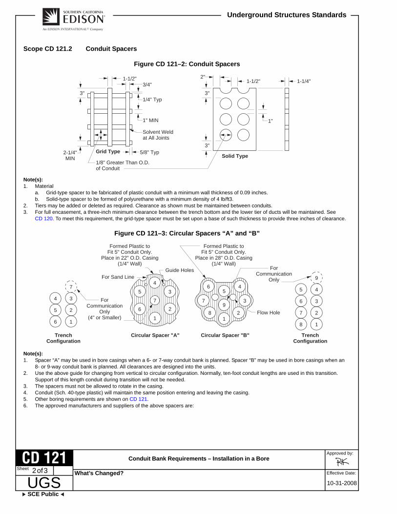
Scope CD 121.2 Conduit Spacers
Figure CD 121–2: Conduit Spacers
Note(s): 1. Material
a. Grid-type spacer to be fabricated of plastic conduit with a minimum wall thickness of 0.09 inches.b. Solid-type spacer to be formed of polyurethane with a minimum density of 4 lb/ft3.
2. Tiers may be added or deleted as required. Clearance as shown must be maintained between conduits.3. For full encasement, a three-inch minimum clearance between the trench bottom and the lower tier of ducts will be maintained. See
CD 120. To meet this requirement, the grid-type spacer must be set upon a base of such thickness to provide three inches of clearance.
Figure CD 121–3: Circular Spacers “A” and “B”
Note(s): 1. Spacer “A” may be used in bore casings when a 6- or 7-way conduit bank is planned. Spacer “B” may be used in bore casings when an
8- or 9-way conduit bank is planned. All clearances are designed into the units.2. Use the above guide for changing from vertical to circular configuration. Normally, ten-foot conduit lengths are used in this transition.
Support of this length conduit during transition will not be needed.3. The spacers must not be allowed to rotate in the casing.4. Conduit (Sch. 40-type plastic) will maintain the same position entering and leaving the casing.5. Other boring requirements are shown on CD 121.6. The approved manufacturers and suppliers of the above spacers are:
Solid Type
Solvent Weldat All Joints
1"
1-1/4"1-1/2"1-1/2" 2"
3"3"
3"
1" MIN
2-1/4"MIN
1/4" Typ
5/8" Typ
1/8" Greater Than O.D.of Conduit
3/4"
Grid Type
6
5
4
1
2
3
7
8
7
5
1
2
4
9
6 3
Formed Plastic toFit 5" Conduit Only.
Place in 22" O.D. Casing(1/4" Wall)
ForCommunication
Only(4" or Smaller)
ForCommunication
Only
Formed Plastic toFit 5" Conduit Only.
Place in 28" O.D. Casing(1/4" Wall)
Guide Holes
Flow Hole
Circular Spacer "A" Circular Spacer "B" TrenchConfiguration
TrenchConfiguration
For Sand Line
1
2
6
7
8
4
3
21
9
53
4
5
6
7
What’s Changed?

Conduit Bank Requirements – Installation in a Bore
SCE Public
Approved by:
UGSSheet
Underground Structures Standards
Effective Date: 3 of 3
10-31-2008
CD 121
Table CD 121–2: Conduit Spacers – Approved Manufacturers and Suppliers
Mfr. Underground Products
Suppliers Armorcast Products Company13230 Saticoy StreetNorth Hollywood, CA 91605
What’s Changed? The approved manufacturer information has been updated.

This page intentionally left blank.
Conduit Beam Reinforcement
SCE Public
Approved by:
UGSSheet
Underground Structures Standards
Effective Date: 1 of 1
01-26-2007
CD 122
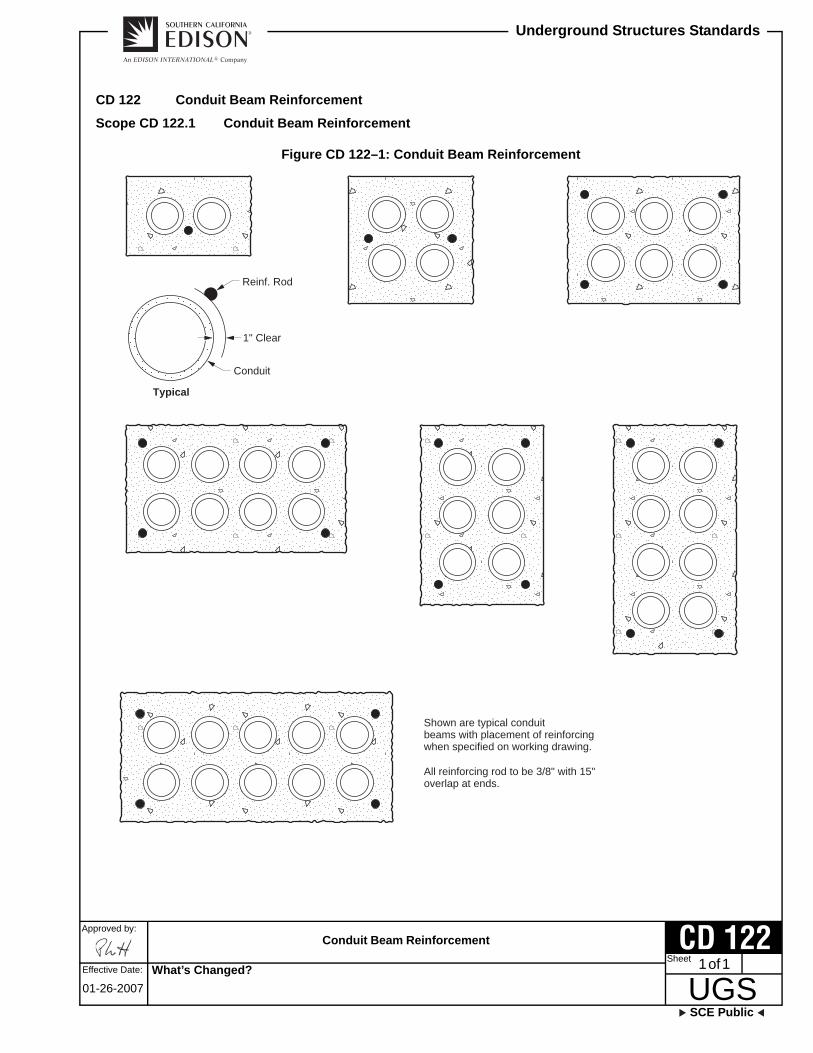
CD 122 Conduit Beam Reinforcement
Scope CD 122.1 Conduit Beam Reinforcement
Figure CD 122–1: Conduit Beam Reinforcement
1" Clear
Typical
Shown are typical conduitbeams with placement of reinforcingwhen specified on working drawing.
All reinforcing rod to be 3/8" with 15"overlap at ends.
Reinf. Rod
Conduit
What’s Changed?

This page intentionally left blank.

Directional Boring Installation Standards
SCE Public
Approved by:
UGSSheet
Underground Structures Standards
Effective Date: 1 of 3
07-26-2013
CD 125
CD 125 Directional Boring Installation Standards
Scope CD 125.1 Directional Boring Installation Standards
1.0 General
These standards are intended as a minimum requirement for installing conduit by directional boring, tunneling, jacking, or plowing. All specific requirements shown on working drawings, governmental permits, and all applicable cities, counties, and state ordinances shall also be in compliance. References to contractor signify the organization performing the specified work.
Horizontal directional boring is a form of trenchless technology. The equipment and procedures are intended to minimize surface damage, restoration requirements, and disruption of vehicular and maritime traffic with little or no interruption of other existing lines or services.
If a cable system is to be installed by boring and the soil and surface loading conditions are such that solid material in the region may damage the cable, then the cable shall be adequately protected.
The location of structures in the path of the projected cable route shall, as far as practical, be determined prior to trenching, boring, tunneling, jacking, or plowing operation.
2.0 Duct Systems
Open trenching, tunneling, boring, jacking, plowing, either singularly or in combination, are among the recognized methods of installing duct systems.
3.0 Contractor Responsibilities Performing Directional Boring
3.1 Prior to performing directional boring, call Underground Service Alert (USA) 48 hours before boring at 811.
3.2 The contractor will furnish all equipment, labor, tools, supervision, and approved duct (See CD 115) required when installing the duct system.
3.3 Damage to sub structures, equipment, or plant caused by the contractor will be repaired by contractor at their expense to the satisfaction of SCE.
3.4 Settling or washout of trench or bore pit areas within one year of acceptance of work will be repaired at contractor’s expense and to the satisfaction of SCE.
3.5 The contractor is responsible for informing SCE of any deviation to working drawings.
3.6 The contractor must gain permission from the Region Underground Civil Construction Manager before any deviation to the working drawings can commence.
3.7 The Contractor is responsible for informing SCE 24 Hours in advance prior to any Bore Installation.
3.8 The Contractor shall place conduit at the proper depth and in line with what would be a trench line. This shall be accomplished by either a locater with depth readings or potholing at 10 feet minimum.
What’s Changed?

Directional Boring Installation Standards
Approved by:
UGSSCE Public
Underground Structures Standards
Effective Date:2 of 3
07-26-2013
CD 125Sheet
4.0 Construction Requirements for Directional Boring
4.1 Only approved Schedule 40 Bore Guard or Long Bell Length Conduit approved by SCE Engineering (see CD 100) will be installed.
4.2 Installation of the duct system will generally be from an Installation pit and a Receiving pit.
4.3 Install conduit at a minimum of 30 inches in depth (60 inches maximum). Minimum cover at water crossings (specified on the working drawing) will be 60 inches. A locator following along the direction of the bore will ensure the depth requirement is met.
4.4 A maximum of 2 conduits will be allowed to be installed by directional boring, tunneling, and jacking. For installations requiring more than 2 conduits refer to CD 120.
5.0 Directional Boring Construction Closeout
Upon completion of directional boring, tunneling, and jacking, the ground surface will be restored to its previous condition prior to the start of work. All applicable local compaction requirements shall be met. If required by permit, the installation and receiving pits shall be replanted or seeded.
Figure CD 125–1: Typical Boring Installation
Pot Hole
Locator
Boring Unit
Pot Hole
Drill String
Installation PitDrill Head
What’s Changed? Section 4.3 was updated to include a depth of 60 inches maximum for conduit installations.

Directional Boring Installation Standards
SCE Public
Approved by:
UGSSheet
Underground Structures Standards
Effective Date: 3 of 3
07-26-2013
CD 125
6.0 SCE Responsibilities – Directional Boring
6.1 SCE will inspect work in progress.
6.2 Final Acceptance will be based on the inspection performed by SCE.
What’s Changed? Section 6.1 stating "SCE will furnish all necessary permits" was removed.

This page intentionally left blank.

Standard Conduit Entrance Details
SCE Public
Approved by:
UGSSheet
Underground Structures Standards
Effective Date: 1 of 2
01-26-2007
CD 130
CD 130 Standard Conduit Entrance Details
Scope CD 130.1 Standard Conduit Entrance Details
Figure CD 130–1: Standard Conduit Entrance Details
Figure CD 130–1.1: Plan Section
Figure CD 130–1.2: Elevation
8"
7" 7"
12"
"X"
See Note 7.
See Note 8.
See “Note A.”
Roof
Floor
Wal
l
18"
8" MIN
24" MIN
7"
ServiceLaterals
MainLine
Conduits
A
A
"X"
See “Note A.”
What’s Changed?
Standard Conduit Entrance Details
Approved by:
UGSSCE Public
Underground Structures Standards
Effective Date:2 of 2
01-26-2007
CD 130Sheet
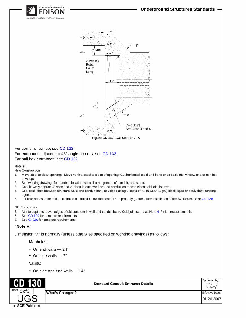
Figure CD 130–1.3: Section A-A
For corner entrance, see CD 133.For entrances adjacent to 45° angle corners, see CD 133.For pull box entrances, see CD 132.
Note(s): New Construction1. Move steel to clear openings. Move vertical steel to sides of opening. Cut horizontal steel and bend ends back into window and/or conduit
envelope.2. See working drawings for number, location, special arrangement of conduit, and so on.3. Cast keyway approx. 4" wide and 2" deep in outer wall around conduit entrances when cold joint is used.4. Seal cold joints between structure walls and conduit bank envelope using 2 coats of “Sika-Seal” (1 gal) black liquid or equivalent bonding
agent.5. If a hole needs to be drilled, it should be drilled below the conduit and properly grouted after installation of the BC Neutral. See CD 120.
Old Construction6. At interceptions, bevel edges of old concrete in wall and conduit bank. Cold joint same as Note 4. Finish recess smooth.7. See CD 100 for concrete requirements.8. See GI 020 for concrete requirements.
“Note A”
Dimension “X” is normally (unless otherwise specified on working drawings) as follows:
Manholes:
On end walls — 24"
On side walls — 7"
Vaults:
On side and end walls — 14"
12"
8" MIN
8"
8"
7"
Cold JointSee Note 3 and 4.
2-Pcs #3RebarEa. 4'Long
What’s Changed?

Standard and Special Conduit Entrances
SCE Public
Approved by:
UGSSheet
Underground Structures Standards
Effective Date: 1 of 3
01-26-2007
CD 131
CD 131 Standard and Special Conduit Entrances
Scope CD 131.1 Standard and Special Conduit Entrances
Special Recess
To be used in all 4" x 4" manholes. May be used elsewhere only when specified on working drawings.
Standard Conduit Entrance
For conduit adjacent to 45° angle corners.
Figure CD 131–1: Standard and Special Conduit Entrances
Figure CD 131–1.1: Plan Section
Figure CD 131–1.2: Plan Section
AA
7"
7"
7"
BB
45° AngleRecess
12"7"
7"4"
What’s Changed?

Standard and Special Conduit Entrances
Approved by:
UGSSCE Public
Underground Structures Standards
Effective Date:2 of 3
01-26-2007
CD 131Sheet
Figure CD 131–1.3: Elevation
Figure CD 131–1.4: Section A-A
Figure CD 131–1.5: Section B-B
8" MIN
24" MIN
12"
8" MIN
4"
8" MIN
What’s Changed?

Standard and Special Conduit Entrances
SCE Public
Approved by:
UGSSheet
Underground Structures Standards
Effective Date: 3 of 3
01-26-2007
CD 131
Figure CD 131–1.6: Staggered Conduit Entrance (Not Optional) —Use only when specified on working drawings.
Note(s): 1. Move steel to clear openings. Move vertical steel to sides of opening. Cut horizontal steel and bend ends back into window and/or conduit
envelope.2. See working drawings for number, location, special arrangement of conduit, and so on.3. Old construction: At interceptions, bevel edges of old concrete in wall and/or conduit bank and seal joint between structure using 2 coats of
“sikaseal” (1 gal) black liquid, or equivalent bonding agent, finish recess smooth.4. If a hole needs to be drilled, it should be drilled below the conduit and properly grouted after installation of the BC Neutral. See CD 120.
Top and bottominside edges ofconduit to havecommon horizontaltangent lines.
Face of recess
What’s Changed?

This page intentionally left blank.

Conduit Entrances to Pull Boxes
SCE Public
Approved by:
UGSSheet
Underground Structures Standards
Effective Date: 1 of 2
01-26-2007
CD 132
CD 132 Conduit Entrances to Pull Boxes
Scope CD 132.1 Conduit Entrances to Pull Boxes
Figure CD 132–1: Conduit Entrances to Pull Boxes — Typical Conduit Entrances for Deep Recess Pull Boxes
Figure CD 132–1.1: Cut Away Section
Figure CD 132–1.2: End Elevation
Note(s): 1. Where H.D.G. conduit is used, tape end of pipe to fit inside of end bell.2. Conduit will enter and leave pull boxes in line and parallel to floor.3. End bells to be of transite, PVC, or ABS for all types of conduit.4. Inserts to be “Richmond coil type” or pull iron per AC 729.
6"
1" InsertSee Note 4.
1" InsertSee Note 4.
Where laterals are indicated in side walls,end bells to be used. See Note 3.
1-1/2"1"
What’s Changed?
Conduit Entrances to Pull Boxes
Approved by:
UGSSCE Public
Underground Structures Standards
Effective Date:2 of 2
01-26-2007
CD 132Sheet
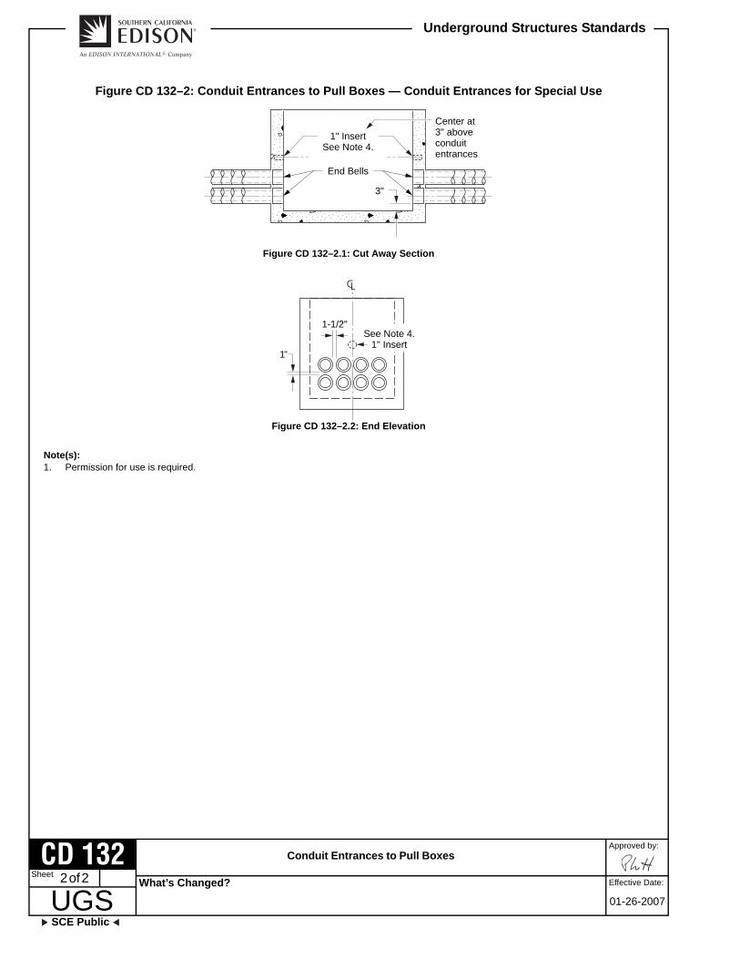
Figure CD 132–2: Conduit Entrances to Pull Boxes — Conduit Entrances for Special Use
Figure CD 132–2.1: Cut Away Section
Figure CD 132–2.2: End Elevation
Note(s): 1. Permission for use is required.
1" InsertSee Note 4.
End Bells
Center at3" aboveconduitentrances
3"
See Note 4.1" Insert
1-1/2"
1"
What’s Changed?

Corner Conduit Entrance Details — Manhole or Vault
SCE Public
Approved by:
UGSSheet
Underground Structures Standards
Effective Date: 1 of 2
01-26-2007
CD 133
CD 133 Corner Conduit Entrance Details — Manhole or Vault
Scope CD 133.1 Corner Conduit Entrance Details — Manhole or Vault
Figure CD 133–1: Corner Conduit Entrance Details — Manhole or Vault
Figure CD 133–1.1: Section A-A — Corner Conduit Entrance when Conduit are Cast in Walls at Time of Vault Construction
Note(s): 1. Corner conduit entrance when conduit are cast in walls at time of vault construction.
Figure CD 133–1.2: Section A-A — Corner Conduit Entrance when Window is Left at Time of Vault Construction
Note(s): 1. Leave window through corner to clear outside ducts by 4" all around. Concrete in window and around ducts. Finish recess face flush with
conduit ends.
20"
Wall
Wal
l8"
B
B
Cold JointSee Note 4.See Note 7.
See Note 8.20
"
Wall
Wal
l
8"
8"
What’s Changed?

Corner Conduit Entrance Details — Manhole or Vault
Approved by:
UGSSCE Public
Underground Structures Standards
Effective Date:2 of 2
01-26-2007
CD 133Sheet
Figure CD 133–1.3: Elevation
Note(s): 1. Finish bottom shelf with 45° slope or leave 8" clear below bottom duct and finish with a level shelf.
Figure CD 133–1.4: Section B-B
Note(s): 1. Move steel to clear opening. Move vertical steel to sides of opening. Cut horizontal steel, turn ends back into recess or conduit bank
encasement.2. See working drawings for number, locations, and special arrangements of conduits, and so forth.3. Cast keyway approximately four inches wide by two inches deep in outer wall around conduit entrances when cold joint is used.4. Seal cold joints between structure walls and conduit bank envelope. Using two coats “Sikaseal” (one gallon) black liquid, or equivalent
bonding agent.5. At interceptions, bevel edges of old concrete in wall and conduit bank.6. See CD 132 for pull box conduit entrances.7. See CD 100 for concrete requirements.8. See GI 020 for concrete requirements.
AA
8" MIN
8" MIN
24" MIN7"
What’s Changed?

Conduit Terminators
SCE Public
Approved by:
UGSSheet
Underground Structures Standards
Effective Date: 1 of 1
10-31-2008
CD 134
CD 134 Conduit Terminators
Scope CD 134.1 Conduit Terminators
Figure CD 134–1: Conduit Terminators
Note(s): 1. Conduit will be terminated into substructure with conduit terminators.2. Conduit termination at wall will be concrete encased to the minimum dimensions shown on the drawing CD 112. For concrete encasement
mix, see CD 100.3. Face of terminator will be placed flush with inside surface of structure and sealed in position with a dry packed nonshrinkable mortar mix.4. Conduit terminator to be made of PVC or ABS plastic. They will be provided with a minimum of three outer water stop ridges, minimum 3/8"
high positioned between the ends, as shown on the drawing.5. Terminator may be obtained from:
a. Manufacturers/Suppliers:Jensen Precast14221 San Bernardino Ave.Fontana, CA 92335
b. Manufacturers/Suppliers:Utility Vault Co.P.0.Box 1390Fontana, CA 92355
6" MIN
ConcreteEncasementSee Note 2.
Water StopRidges
InsideStructure
Wall
Dry-PackedNonshrink Mortar
See Note 3.
Conduit TerminatorSee Note 4.
12" MIN
ConduitSee Note 1.
OutsideStructureWall
Core Drill for Field Installation 2" Larger Than
Outer Diameter of Terminator. Rough Inside
of Core Drilled Hole for Mortar Adhesion
What’s Changed? The approved manufacturer information has been updated.

This page intentionally left blank.
Typical Installation of Precast Pull Box in Main Line Conduit
SCE Public
Approved by:
UGSSheet
Underground Structures Standards
Effective Date: 1 of 2
01-26-2007
CD 135
CD 135 Typical Installation of Precast Pull Box in Main Line Conduit
Scope CD 135.1 Typical Installation of Precast Pull Box in Main Line Conduit
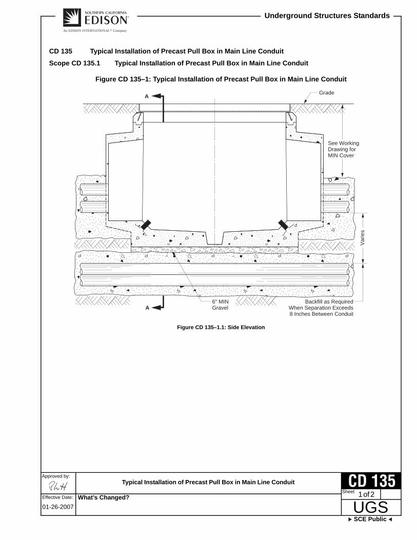
Figure CD 135–1: Typical Installation of Precast Pull Box in Main Line Conduit
Figure CD 135–1.1: Side Elevation
See WorkingDrawing forMIN Cover
Backfill as RequiredWhen Separation Exceeds8 Inches Between Conduit
Grade
A
A
6" MINGravel
Var
ies
What’s Changed?

Typical Installation of Precast Pull Box in Main Line Conduit
Approved by:
UGSSCE Public
Underground Structures Standards
Effective Date:2 of 2
01-26-2007
CD 135Sheet
Figure CD 135–1.2: Section A-A
Note(s): 1. Ducts can be 4 wide in 2-1/2' x 4' and 3' x 5' pull boxes only.
Grade
LateralSee Note 1.
6"
What’s Changed?

Standard Conduit Location for Precast Vaults and Manholes 6' x 12' and Larger
SCE Public
Approved by:
UGSSheet
Underground Structures Standards
Effective Date: 1 of 1
01-26-2007
CD 140
CD 140 Standard Conduit Location for Precast Vaults and Manholes 6' x 12' and Larger
Scope CD 140.1 Standard Conduit Location for Precast Vaults and Manholes 6' x 12' and Larger
Figure CD 140–1: Standard Conduit Location for Precast Vaults and Manholes 6' x 12' and Larger
Note(s): 1. With SCE Company approval, small variations in design may be allowed precasters in order to accommodate individual methods of
manufacturing.2. See CD 142.
EndSection
Center Section
Vault Casting Manhole Casting
TerminatorsSee Note 2.
FourLocationsTwo EachEnd Wall
18" x 18" Rebar Free SectionFour Locations; Two Each Sidewall
What’s Changed?

This page intentionally left blank.

Conduit Recess Layout — Precast Concrete Vaults — 7' x 10', 8' x 10', and Larger
SCE Public
Approved by:
UGSSheet
Underground Structures Standards
Effective Date: 1 of 1
01-26-2007
CD 141
CD 141 Conduit Recess Layout — Precast Concrete Vaults — 7' x 10', 8' x 10', and Larger
Scope CD 141.1 Conduit Terminators
Figure CD 141–1: Standard and Alternate Recess Layouts
Note(s): 1. Standard layout for 7' x 10' and 8' x 10' and copper vault, will consist of two flat-wall conduit recesses, furnished at each end of the
structure.2. Deep recesses will only be furnished when specified on the working drawing.3. Alternate #2 layout is not available on seven-foot wide vaults. For seven-foot wide vaults, see VA 411 for conduit recess dimensions and
terminators.4. When “Alternate #2 Layout“ is required, mark “A” on end where side recesses are required.5. The face of the deep recess on the 8' x 10' long vault will have a minimum height of 32 inches.6. Face of the 8' x 14' and longer vault deep recesses to have a 75-inch minimum height. Minimum height from floor to recess face is
22 inches. Minimum height from recess face to ceilings is eight inches. See CD 142 for other conduit recess dimensions and terminators.7. With SCE Company approval, small variations in design may be allowed precasters in order to accommodate individual methods of
manufacturing.
Flat-WallRecess(See Note 1.)
Standard Recess Layout
FurnishTwo RecessesEach End
12"
Furnish Recesson One End Only(One Each Side)7"1"
MIN
"A"
Alternate #2 LayoutAlternate #1 Layout
Alternate Recess Layout
Deep Recesses(See Notes 2 and 6.)
FurnishTwo Recesses
Each EndWall
FOR R
EFERENCE O
NLY
What’s Changed?

This page intentionally left blank.

Conduit Terminators for Precast Tunnel Vaults
SCE Public
Approved by:
UGSSheet
Underground Structures Standards
Effective Date: 1 of 2
01-26-2007
CD 142
CD 142 Conduit Terminators for Precast Tunnel Vaults
Scope CD 142.1 Conduit Terminators for Precast Tunnel Vaults
Figure CD 142–1: Conduit Terminators for Precast Tunnel Vaults
Figure CD 142–1.1: Vault Top View
21
43
65
87
109
1211
10"
25"
10"1' Diameter Sch. 40PVC Conduit, CappedFlush With Outside Wall.For Neutral Wire
12-5" or 6" Terminators
Side-Wall
7"
StandardFlat Wall
StandardTerminatorLocations
What’s Changed?
Unless specified otherwise, mainline conduits will be installed in the terminators in numerical order starting with position 5.
Working drawings or inspector may change positions for special cases.

Conduit Terminators for Precast Tunnel Vaults
Approved by:
UGSSCE Public
Underground Structures Standards
Effective Date:2 of 2
01-26-2007
CD 142Sheet
Figure CD 142–1.2: Side View
1.0 Requirements:
1. Two sets of 12 five-inch or six-inch terminators, as specified, will be furnished in each end wall unless otherwise specified on working drawing.
2. Terminators must provide a watertight seal with or without conduits installed.
3. Reducers will be furnished (number per working drawing) when small diameter conduit is to be installed. Reduced conduit will be finished flush with inside recess wall and grouted (Figure CD 142–1.2 [Sheet 2]).
Grout
Cement
Cement
Reducer
ConduitInsideFace ofVault Wall
Terminator
What’s Changed?
Conduit Bank Entrance to Power Cable Trench Where Trench Extension is Planned
SCE Public
Approved by:
UGSSheet
Underground Structures Standards
Effective Date: 1 of 2
10-26-2012
CD 144
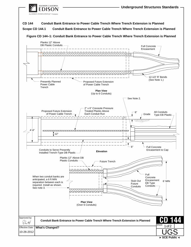
CD 144 Conduit Bank Entrance to Power Cable Trench Where Trench Extension is Planned
Scope CD 144.1 Conduit Bank Entrance to Power Cable Trench Where Trench Extension is Planned
Figure CD 144–1: Conduit Bank Entrance to Power Cable Trench Where Trench Extension is Planned
Planks 12" AboveDB Plastic Conduits Full Concrete
Encasement
Presently PlannedPower CableTrench
Proposed Future Extensionof Power Cable Trench
Plan View(Up to 6 Conduits)
12-1/2' R' Bends(See Note 1.)
4'-6"12"
6"
6"
All ConduitsType EB PlasticGrade
Full ConcreteEncasement to Cap
Proposed Future Extensionof Power Cable Trench
Conduits to Serve PresentlyInstalled Trench-Type DB Plastic
2" x 6" Creosote PressureTreated Planks AboveEach Conduit Run
See Note 2.
Elevation
6' MIN
Planks 12" Above DBPlastic Conduits Future Trench
Stub OutFutureConduits
FullConcreteEncasementEB TypeConduits
When two conduit banks areanticipated, a 6 ft MINseparation between each isrequired. Install as shown. See note 3.
Plan View(Over 6 Conduits)
What’s Changed?

Conduit Bank Entrance to Power Cable Trench Where Trench Extension is Planned
Approved by:
UGSSCE Public
Underground Structures Standards
Effective Date:2 of 2
10-26-2012
CD 144Sheet
Note(s): 1. See MC 800.2. Cap conduits per CD 148 for extending into future trench.3. See MC 800 for additional details.
What’s Changed? The acronym for the Miscellaneous Chapter of the UGS Manual has been changed from ’MS’ to ’MC’ for clarity.
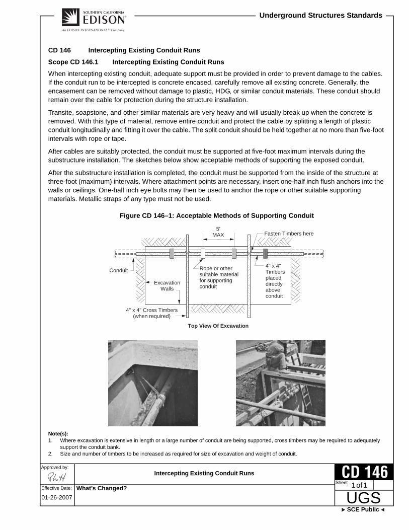
Intercepting Existing Conduit Runs
SCE Public
Approved by:
UGSSheet
Underground Structures Standards
Effective Date: 1 of 1
01-26-2007
CD 146
CD 146 Intercepting Existing Conduit Runs
Scope CD 146.1 Intercepting Existing Conduit Runs
When intercepting existing conduit, adequate support must be provided in order to prevent damage to the cables. If the conduit run to be intercepted is concrete encased, carefully remove all existing concrete. Generally, the encasement can be removed without damage to plastic, HDG, or similar conduit materials. These conduit should remain over the cable for protection during the structure installation.
Transite, soapstone, and other similar materials are very heavy and will usually break up when the concrete is removed. With this type of material, remove entire conduit and protect the cable by splitting a length of plastic conduit longitudinally and fitting it over the cable. The split conduit should be held together at no more than five-foot intervals with rope or tape.
After cables are suitably protected, the conduit must be supported at five-foot maximum intervals during the substructure installation. The sketches below show acceptable methods of supporting the exposed conduit.
After the substructure installation is completed, the conduit must be supported from the inside of the structure at three-foot (maximum) intervals. Where attachment points are necessary, insert one-half inch flush anchors into the walls or ceilings. One-half inch eye bolts may then be used to anchor the rope or other suitable supporting materials. Metallic straps of any type must not be used.
Figure CD 146–1: Acceptable Methods of Supporting Conduit
Note(s): 1. Where excavation is extensive in length or a large number of conduit are being supported, cross timbers may be required to adequately
support the conduit bank.2. Size and number of timbers to be increased as required for size of excavation and weight of conduit.
Conduit
ExcavationWalls
Rope or othersuitable materialfor supportingconduit
5'MAX
Top View Of Excavation
4" x 4" Cross Timbers(when required)
4" x 4"Timbersplaceddirectlyaboveconduit
Fasten Timbers here
What’s Changed?

This page intentionally left blank.

Capping Main Line Conduit
SCE Public
Approved by:
UGSSheet
Underground Structures Standards
Effective Date: 1 of 1
01-26-2007
CD 148
CD 148 Capping Main Line Conduit
Scope CD 148.1 Capping Main Line Conduit
Figure CD 148–1: Capping Main Line Conduit
Note(s): 1. When capping unencased conduit (two maximum), install conduit plug in coupling same as shown above (do not stagger).2. See CD 120 for conduit spacing and concrete encasement.3. Conduit plug types 1, 2, and 3 are not recommended for this application.4. Where a conduit is stubbed out to curb or property line to be picked up later, it must terminate on a level course at a minimum depth of
30 inches from flow line of gutter unless specified otherwise.5. Stubbed conduit to have location, marked at time of installation, by one of the following methods: Curb to be marked by chiseling an “E”
on curb face, or 2" x 4" board, or pull rope or pull tape installed at capped conduit and extended to 12 inches below the surface.6. See CD 180.
Typical Conduit Bank
Pour concrete againsttemporary wooden barrierheld flush against couplings.
Coupling
Completed Capped Conduit Assembly
Remove wooden barrierand install approvedconduit plug (see note 6).Plug will provide awatertight fit withoutcement.
Conduit plug type SF or DC(see note 6).
What’s Changed?

This page intentionally left blank.

Service Lateral Terminations
SCE Public
Approved by:
UGSSheet
Underground Structures Standards
Effective Date: 1 of 1
01-26-2007
CD 150
CD 150 Service Lateral Terminations
Scope CD 150.1 Service Lateral Terminations
Figure CD 150–1: Service Lateral Terminations
Note(s): 1. All service laterals will terminate in such location that an extension of same will have 12 inches minimum clearance from property line
corner unless specified otherwise.2. See CD 100 for approved type of conduit.3. See CD 100 for general trench, backfill, and concrete requirements.4. See CD 120 for conduit spacing requirements.5. Where a conduit is stubbed out to curb or property line to be picked up later, it must terminate on a level course at a minimum depth of 30
inches from flow line of gutter unless specified otherwise.6. Stubbed conduit to have location marked at time of installation by one of the following methods: Curb to be mark by chiseling an “E” on
curb face, or 2" x 4" board, or pull rope or pull tape installed at capped conduit and extended to 12 inches below the surface.
Customer’s Property
Identical Points
Parkway or Easement
Gutter Grade
SeeNote 3.
System Service Conduit
Typical Conduit Terminations
Customer-installed conduitmaterial requirements subjectto local ordinances.
See SCE Co. ElectricalService Requirements for
Underground Requirementson Customer’s Property.
See Note 5.
Cap or Plugas Shown
Conduit Plug
Terminators for Direct Burial
hot dipped galvanized conduits.Note: Normally not encased in concrete
Nonmetallic Conduit
Solid Pipe PlugCoupling
Encased Conduit Termination
Coupling to be manufacturer’s standardfor type of conduit used.
Conduit Plug
Do not solvent-weldconduit to coupling.
3"MAX
What’s Changed?

This page intentionally left blank.

Pole Riser Bend Standard Location
SCE Public
Approved by:
UGSSheet
Underground Structures Standards
Effective Date: 1 of 2
04-25-2008
CD 160
CD 160 Pole Riser Bend Standard Location
Scope CD 160.1 Pole Riser Bend Standard Location
Figure CD 160–1: Pole Riser Bend Standard Location
Note(s): 1. Approved riser bend materials and sizes are shown in the following table.
Table CD 160–1: Approved Riser Bend Materials and Sizes — Standard Location
2. The top and bottom of three-, four-, five-, or six-inch fiberglass bends are furnished with permanently attached PVC couplings. Also included is a six-inch long, three-, four-, five-, or six-inch Schedule 80 PVC stub-out, solvent welded into the top coupling. See CD 166 for fiberglass riser bend material information and suppliers.
Material
Size
1" 1-1/2" 2" 2-1/2" 3" 4" 5" 6"
ABS — — — X X X X —
Fiberglass — — — — X X X Xa/
a/ Six-inch HDG or Fiberglass riser bend will be used when specified on the working drawing. See AC 702for grounding HDG riser bends.
HDG X X X X X X X Xa/
= For Reference Only
Minimum earth cover overriser bend to be as follows:
3"Grade
#6 (MIN) bare copperto ground rods
2"
1"
Duct
Encasement
Coupling or Adapter
Riser Conduit Spacing Diagram(At Base of Pole)
ConduitSize
HDGCover
FiberglassCover
1"–3"4"–5"
6"
33"57"72"
47"59"74"
Wood molding with #6 (MIN) wire inside to top.
Align riser with a temporary length of conduit;Remove this length when riser is set.
Solvent weld pipe cap onto riser. Do not permit excess cementto ender conduit. Cap HDG bend with concrete-filled coupling.
Ream interior of lower end of ABS riserbend to permit a smooth transition fromthe conduit to the riser.
3" (MIN)24" (MAX)
36" (MIN) radius for 1" to 3" incl.48" (MIN) radius for 4" and 5"60" (MIN) radius for 6" and over
4"WoodMolding
Grounding typical forboth pole configurations
5/8" x 8' copperclad steelground rod and clamp —2 Places 6' (MIN) separation
#6 (MIN) Bare Copper Conduit
Riser Bend
6'(MIN)
Riser Bends
PolePole
What’s Changed? 6" MIN changed to 6' MIN
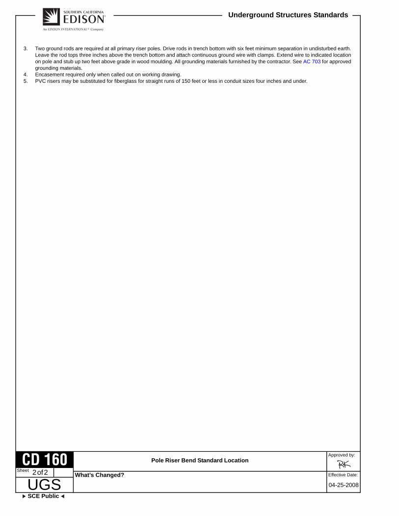
Pole Riser Bend Standard Location
Approved by:
UGSSCE Public
Underground Structures Standards
Effective Date:2 of 2
04-25-2008
CD 160Sheet
3. Two ground rods are required at all primary riser poles. Drive rods in trench bottom with six feet minimum separation in undisturbed earth. Leave the rod tops three inches above the trench bottom and attach continuous ground wire with clamps. Extend wire to indicated location on pole and stub up two feet above grade in wood moulding. All grounding materials furnished by the contractor. See AC 703 for approved grounding materials.
4. Encasement required only when called out on working drawing.5. PVC risers may be substituted for fiberglass for straight runs of 150 feet or less in conduit sizes four inches and under.
What’s Changed?

Pole Riser Bend for Risers on Kicker Blocks
SCE Public
Approved by:
UGSSheet
Underground Structures Standards
Effective Date: 1 of 2
11-10-2011
CD 161
CD 161 Pole Riser Bend for Risers on Kicker Blocks
Scope CD 161.1 Pole Riser Bend for Risers on Kicker Blocks
Figure CD 161–1: Pole Riser Bend for Risers on Kicker Blocks
Note(s): 1. Approved riser bend materials and sizes are shown on the following table.
Table CD 161–1: Approved Riser Bend Materials and Sizes — Risers on Kicker Blocks
Material
Size
1" 1-1/2" 2" 2-1/2" 3" 4" 5" 6"
ABS — — — X X X X —
Fiberglass — — — — X X X Xa/
a/ Six-inch HDG or fiberglass riser bend will be used when specified on the working drawing. See AC 702 forgrounding HDG riser bends.
HDG X X X X X X X X
= For Reference Only
Minimum earth cover overriser bend to be as follows:
3"Grade
#6 (MIN) bare copperto ground rods
2"
1"
Duct
EncasementSee Note 4.
Coupling or Adapter
ConduitSize
HDGCover
FiberglassCover
1"–3"4"–5"
6"
33"57"72"
47"59"74"
Wood molding with #6 (MIN) wire inside to top.
Align riser with a temporary length of conduit;Remove this length when riser is set.
Solvent weld pipe cap onto riser. Do not permit excess cementto ender conduit. Cap HDG bend with concrete-filled coupling.
Ream interior of lower end of ABS riserbend to permit a smooth transition fromthe conduit to the riser.
3" (MIN)24" (MAX)
36" (MIN) radius for 1" to 3" incl.48" (MIN) radius for 4" and 5"60" (MIN) radius for 6" and over
Riser Bends
Riser Conduit Spacing Diagram(At Base of Pole)
2"
WoodMolding
Conduit
RiserBend
2"2"
2"2"
2"2"
2" 2"Riser Bend
3-1/4" Wood Kickers, 3-1/4" UnistrutKickers (see SCE Inspector)
Pole Pole
Grounding typical forboth pole configurations
5/8" × 8' copperclad steelground rod and clamp —2 Places 6' (MIN) separation
#6 (MIN) Bare Copper
6"(MIN)
Pole
What’s Changed? Figure CD 161-1 was updated to reflect 3 1/4" unistrut kickers.

Pole Riser Bend for Risers on Kicker Blocks
Approved by:
UGSSCE Public
Underground Structures Standards
Effective Date:2 of 2
11-10-2011
CD 161Sheet
2. The top and bottom of three-, four-, five-, or six-inch fiberglass bends are furnished with permanently attached PVC couplings. Also included is a six-inch long, three-, four-, five-, or six-inch Schedule 80 PVC stub-out, solvent welded into the top coupling. See CD 166 for fiberglass riser bend material information and suppliers.
3. Two ground rods are required at all primary riser poles. Drive rods in trench bottom with six feet minimum separation in undisturbed earth. Leave the rod tops three inches above the trench bottom and attach continuous ground wire with clamps. Extend wire to indicated location on pole and stub up two feet above grade in wood moulding. All grounding materials furnished by the contractor. See AC 703 for approved grounding materials.
4. Encasement required only when called out on working drawing.5. Schedule 80 PVC bends may be substituted for fiberglass bends for straight runs of 150 feet or less in conduit sizes four inches and under.
What’s Changed?

Neutral Wire Riser Installation for Four-Wire Systems
SCE Public
Approved by:
UGSSheet
Underground Structures Standards
Effective Date: 1 of 1
07-27-2007
CD 162
CD 162 Neutral Wire Riser Installation for Four-Wire Systems
Scope CD 162.1 Neutral Riser Wire Installation for Four-Wire Systems
Figure CD 162–1: Neutral Riser Wire Installation for Four-Wire Systems
Note(s): 1. See CD 160.2. See CD 161.3. Install bare copper neutral wire only when specified on working drawing. For mainline applications (including 4-wire taplines) when the
neutral is present on an overhead structure that feeds a primary riser, the neutral shall be continuous to the first underground structure. A bare copper neutral wire, as specified on the working drawing, shall be placed, and fully encased in contrete, at the lower region of the duct bank, preferably in-between conduits.
Extend 4/0 B.C.6" above 1" conduitand staple to pole.
1" Sch. 80 PVC ConduitSpaced 1/2" off Pole
4/0 Bare Copper Neutral Wireto First Underground Structure(See Note 3.)
Grade
Attach at 2 placesbelow grade withpipe strap and 1/2"spacer.
6"
18"
Pole
1/2"
Typical LocationOne or Two Risers
(See Note 1.)
Alternative NeutralLocation (When tworisers 4" or lessin size are installed)
1" NeutralRiserStub-Out
4"
POLE
RiserBend
Typical LocationMore than Two Risers
(See Note 2.)
4"
2"
3-1/4"
POLE
1" NeutralRiserStub-Out
Riser Bends
What’s Changed? Note 3 is now written out instead of referenced.

This page intentionally left blank.

Communication Conduit and Riser Bend Installation
SCE Public
Approved by:
UGSSheet
Underground Structures Standards
Effective Date: 1 of 1
01-26-2007
CD 163
CD 163 Communication Conduit and Riser Bend Installation
Scope CD 163.1 Communication Conduit and Riser Bend Installation
Figure CD 163–1: Communication Conduit and Riser Bend Installation
Note(s): 1. All communication conduits to be four inches minimum for vault-to-vault or manhole-to-manhole runs. Install three-inch conduit from “Y”
fitting, or last vault or manhole to riser pole. Install four-inch “Y” fitting with reducers on pole side per CD 111.2. Unless otherwise specified, communication conduit will be against pole.3. See CD 180.
Location at Base of Pole
3" CommunicationRiser
3"3"
Spacer
3"
Communication4" Conduit
(MIN)See Note 1.
Typical Conduit Bank(See Note 1.)
Riser Pole
Minimum earth cover overriser bend to be as follows:
3" conduit to first vault,manhole, or "Y" fitting
Grade
Couplingor
AdapterConduit
SizeHDGCover
0"–3-1/2" 33"
Align riser with a temporary length of conduit;Remove this length when riser is set.
Cap bend with concrete-filled coupling orriser cap. (See Note 3.)
3" (MAX)
End of curve tobe flush with orbelow final grade.
3" (MIN)24" (MAX)
3" Schedule 80 PVC Bend36" Minimum Radius
Pole
What’s Changed?

This page intentionally left blank.

Specification for Abandoning Conduit and Risers
SCE Public
Approved by:
UGSSheet
Underground Structures Standards
Effective Date: 1 of 1
01-26-2007
CD 164
CD 164 Specification for Abandoning Conduit and Risers
Scope CD 164.1 Specification for Abandoning Conduit and Risers
1.0 Conduit
1.1 Any conduit that is exposed will be removed from the ground.
1.2 The substructure end of any abandoned conduit will be permanently sealed against the entrance of water, gas, or other foreign substances.
2.0 Risers
Any conduit extending above ground will be cut off a minimum of 18 inches below ground level and permanently sealed. (See Figure CD 164–1 [Sheet 1].)
Figure CD 164–1: Specification for Abandoning Conduit and Risers
Rags
One Mixed Sackof Concrete Mix
Remove Cut-OffSection
Cut off riser 18" below grade,remove cut off section, plugremaining conduit with ragsand pour one mixed sack ofconcrete mix over pluggedconduit.
Grade
18" MIN
RemovedPole
What’s Changed?

This page intentionally left blank.

Three-, Four-, Five-, or Six-Inch Fiberglass Riser Bends
SCE Public
Approved by:
UGSSheet
Underground Structures Standards
Effective Date: 1 of 1
10-31-2008
CD 166
CD 166 Three-, Four-, Five-, or Six-Inch Fiberglass Riser Bends
Scope CD 166.1 Three-, Four-, Five-, or Six-Inch Fiberglass Riser Bends
Figure CD 166–1: Three-, Four-, Five-, or Six-Inch Fiberglass Riser Bends
Note(s): 1. The riser bend is available in three-, four-, five-, or six-inch sizes. The main body of the bend is manufactured from fiberglass material and
is medium gray in color.2. The top and bottom of riser bend is furnished with PVC couplings permanently epoxy bonded to the fiberglass bend. A Schedule 80 PVC
six-inch long stub-out is solvent welded into the top PVC coupling.3. The top Schedule 80 PVC stub-out of bend is stenciled “TOP,” and bottom of bend is stenciled “UNDERGROUND.” Manufacturers name,
size, and date (month and year) will be stenciled on the center of the riser bend.4. The top of Schedule 80 PVC stub-out will be placed three inches above final grade. No portion of the fiberglass material of the bend will be
exposed above the finish grade.5. The approved manufacturers and suppliers are:
a. Manufacturers: FRE Conduit, Smith Product Company, and Champion Fiberglass, Inc.b. Suppliers:•. Armorcast Products Company
13230 Saticoy StreetNorth Hollywood, CA 91605
•. Cal-Duct, Inc.2522 Lee AvenueSouth El Monte, CA 91733
•. SAF-T-CO Supply, Inc.1300 E. Normandy PlaceSanta Ana, CA 92705
UNDERGROUND
Schedule 80 PVC ConduitSee Note 2.
Riser Bend MarkingSee Note 3.
Final GradeSee Note 4.
PVC CouplingSee Note 2.
Riser Bend MarkingSee Note 3.
Riser Bend MarkingSee Note 3.
PVC CouplingSee Note 2.
UndergroundConduit
3"6" TOP
Riser Bend Radius3"—36"4"—48"5"—48"6"—60"
90°
Fiberglass Riser BendSee Note 1.
What’s Changed? The approved manufacturer information has been updated.

This page intentionally left blank.

Riser Bend Installation at Wall or Pad
SCE Public
Approved by:
UGSSheet
Underground Structures Standards
Effective Date: 1 of 1
01-26-2007
CD 170
CD 170 Riser Bend Installation at Wall or Pad
Scope CD 170.1 Riser Bend Installation at Wall or Pad
Figure CD 170–1: Riser Bend Installation at Wall or Pad
Note(s): 1. Fiberglass, Schedule 40, or 80 PVC or HDG. PVC is subject to requirements of local ordinances. HDG must be grounded per AC 702.
PVC only for secondary runs and straight primary runs of less than 150 feet length with 4" or smaller duct.
Typical Riser at Building
Typical Riser at Vault or Pad
Plan-View for Two Conduit Terminals
Align riser with a temporary length of conduit;remove this length when riser is set.
BuildingWall
1"
6" (MIN)24" (MAX)
Place pipe cap after removingtemporary conduit.
ConduitSize Radius
EarthCover
0"–3½"4"–5"6"–Up
36"48"60"
33"45"57"
Minmum Dimensionsfor Riser Bends
Coupling or Adapter
End of curve to be flush with orbelow final grade.
Pipe cap for HDG. If PVC is used,solvent weld cap onto riser. Donot permit excess cement to enterconduit.
3"
Coupling or Adapter
Location of riser bend stubis critical. See working drawingfor exact placement.
See Note 1.
See Note 1.
Floor level of vault or pad.
Ream interior of lower end of PVCriser bend to permit a smoothtransition from the conduit to theriser.
Risers
3"
3"
4"
What’s Changed?

This page intentionally left blank.

Underground Risers in Substation
SCE Public
Approved by:
UGSSheet
Underground Structures Standards
Effective Date: 1 of 3
10-26-2012
CD 172
CD 172 Underground Risers in Substation
Scope CD 172.1 Underground Risers in Substation
Figure CD 172–1: Underground Risers in Substation — Plan and Details “A” and “B”
16"
12"
Chamber — 45°
Riser Bend
11"
Centerline ofFoundation Piers
16"
12"
of Bay
PlanLocation for Riser (See Detail “A.”)
Coupling
PVC Sch. 80 Conduit
Riser to be plugged with universal plug conduit.See Note 5.
3'-0" 3"
24"30"
MIN
Conduit
GradePVC Sch. 40 Coupling (Use PVC cement.)
Note: Shape and height ofnew riser piers to conformwith existing in the samerack — otherwise piers are tobe 8" higher than substationfoundation piers.
4/0 BCN from top of riser pierto first underground structure.A 3-foot tail should extend beyond each termination point.
Fiberglass or PVC riser bend.Use PVC for straight runs of150' or less.
Detail “A”Riser for Locations Otherthan Vertical from Trench
Detail “B”Riser for Metal–Clad Unit
Riser to be plugged with universal conduit plug.See Note 5.
Cable TrenchPVCRiserBend
6"
2"
Grade
Variable(Due to type of unit)
Pad for metal-clad unit
What’s Changed?

Underground Risers in Substation
Approved by:
UGSSCE Public
Underground Structures Standards
Effective Date:2 of 3
10-26-2012
CD 172Sheet
Note(s): 1. Conduit — All conduit to be five inches unless noted otherwise. Bends to have 48-inch minimum radius. Material DB-PVC conduit PVC
Schedule 80 conduit (above ground).2. Concrete — Four-inch concrete envelope for all buried conduit. See GI 020 and CD 100.3. Conduit Termination — All conduit ends to be reamed and finished smooth.4. Trench — See MC 800 for trench detail.5. See CD 180.
What’s Changed? The acronym for the Miscellaneous Chapter of the UGS Manual has been changed from ’MS’ to ’MC’ for clarity.
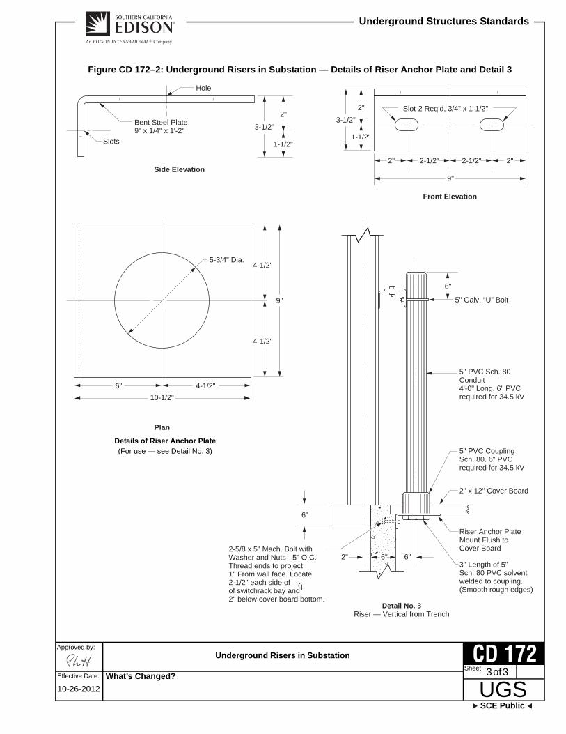
Underground Risers in Substation
SCE Public
Approved by:
UGSSheet
Underground Structures Standards
Effective Date: 3 of 3
10-26-2012
CD 172
Figure CD 172–2: Underground Risers in Substation — Details of Riser Anchor Plate and Detail 3
Slots
Bent Steel Plate9" x 1/4" x 1'-2" 3-1/2"
2"
1-1/2"
Hole
Side Elevation
3-1/2"2"
1-1/2"
2"
Front Elevation
2-1/2"
9"
2-1/2" 2"
Slot-2 Req‘d, 3/4" x 1-1/2"
Detail No. 3Riser — Vertical from Trench
6"
6"
5" Galv. “U” Bolt
5" PVC Sch. 80Conduit4'-0" Long. 6" PVCrequired for 34.5 kV
5" PVC CouplingSch. 80. 6" PVCrequired for 34.5 kV
2" x 12" Cover Board
Riser Anchor PlateMount Flush toCover Board
3" Length of 5"Sch. 80 PVC solventwelded to coupling.(Smooth rough edges)
6"6"2"2-5/8 x 5" Mach. Bolt withWasher and Nuts - 5" O.C.Thread ends to project1" From wall face. Locate2-1/2" each side ofof switchrack bay and2" below cover board bottom.
Details of Riser Anchor Plate(For use — see Detail No. 3)
5-3/4" Dia.4-1/2"
9"
Plan
4-1/2"
6"10-1/2"
4-1/2"
What’s Changed?

This page intentionally left blank.

Streetlight Conduit and Riser Bend Installation for Service to One Streetlight Standard
SCE Public
Approved by:
UGSSheet
Underground Structures Standards
Effective Date: 1 of 3
10-26-2012
CD 175
CD 175 Streetlight Conduit and Riser Bend Installation for Service to One Streetlight Standard
Scope CD 175.1 Typical Conduit and Riser Bend Installation for Service to One Streetlight Standard
Figure CD 175–1: Typical Conduit and Riser Bend Installation for Service to One Streetlight Standard
Note(s): 1. Typical location for streetlight standard:
a. With parkway—place behind inside edge of curb.b. Without parkway—place behind inside edge of sidewalk when curb and sidewalk do not exceed 5-1/2 feet in width, or per local
inspection agency.2. A semi-rigid or rigid conduit bend “DB” thickness minimum will be used when a conventional conduit system is installed. See working
drawing for size and material.3. No encasement required unless otherwise specified.4. In a rigid conduit installation, short lengths of properly coupled conduit may be used to form sweeps of a radius not normally supplied by
manufacturers. In trench runs, the maximum deflection allowed will be 1/2 inch for lengths two feet or shorter, and one inch for lengths over two feet.
5. For riser bends, the minimum radius permitted will be 24 inches; for horizontal bends, a minimum radius of 36 inches.6. A pull rope or pull tape will be installed in each empty conduit.7. See CD 175 for looping installations.8. Five-foot clearance to be maintained from fire hydrant.9. Four-foot clearance to be maintained from top of slope of commercial driveway and two-foot clearance from residential driveway.10. On state highway, the streetlight centerline location will be six inches behind sidewalk when sidewalk is less than seven feet wide.11. See MC 890 for foundation details.12. For new or rebuilt streetlight systems, if space permits or at no additional cost or low cost minor work, maintain a minimum clearance of
36 inches for pedestrian right-of-way access. Avoid streetlight placement in wheelchair ramp locations.
Concrete Footing (See Note 11.)
Conventional Underground Conduit
24" from face of curb or15" from inside edge of sidewalk (See Note 10.)
Face of curb or inside edge of sidewalk(property side)
ConduitRiserBend
1-1/2" or as specified onworking drawing
Light Standard
Elevation
30"State HighwayRequirement
45" (MIN)commercial or
residentialfor CIC
30" (MIN)below gutter grade
for conventionalunderground conduit
Finish Grade Flow Line of Gutter
Plan
CIC
30" Square
What’s Changed? The acronym for the Miscellaneous Chapter of the UGS Manual has been changed from ’MS’ to ’MC’ for clarity.
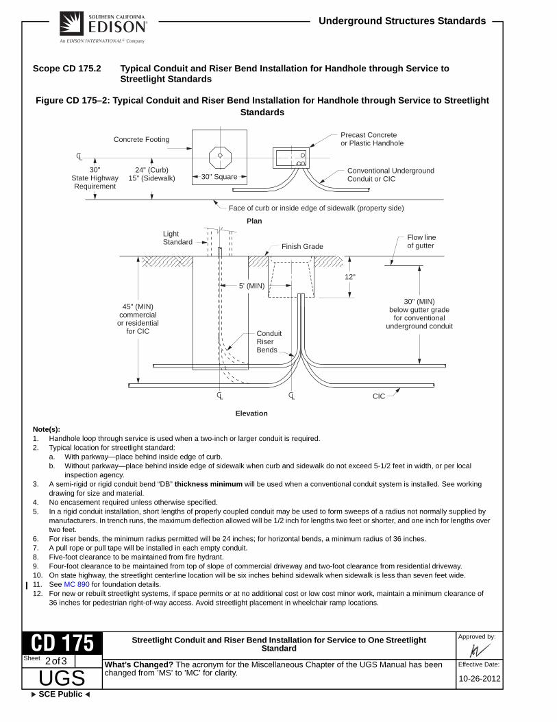
Streetlight Conduit and Riser Bend Installation for Service to One Streetlight Standard
Approved by:
UGSSCE Public
Underground Structures Standards
Effective Date:2 of 3
10-26-2012
CD 175Sheet
Scope CD 175.2 Typical Conduit and Riser Bend Installation for Handhole through Service to Streetlight Standards
Figure CD 175–2: Typical Conduit and Riser Bend Installation for Handhole through Service to Streetlight Standards
Note(s): 1. Handhole loop through service is used when a two-inch or larger conduit is required.2. Typical location for streetlight standard:
a. With parkway—place behind inside edge of curb.b. Without parkway—place behind inside edge of sidewalk when curb and sidewalk do not exceed 5-1/2 feet in width, or per local
inspection agency.3. A semi-rigid or rigid conduit bend “DB” thickness minimum will be used when a conventional conduit system is installed. See working
drawing for size and material.4. No encasement required unless otherwise specified.5. In a rigid conduit installation, short lengths of properly coupled conduit may be used to form sweeps of a radius not normally supplied by
manufacturers. In trench runs, the maximum deflection allowed will be 1/2 inch for lengths two feet or shorter, and one inch for lengths over two feet.
6. For riser bends, the minimum radius permitted will be 24 inches; for horizontal bends, a minimum radius of 36 inches.7. A pull rope or pull tape will be installed in each empty conduit.8. Five-foot clearance to be maintained from fire hydrant.9. Four-foot clearance to be maintained from top of slope of commercial driveway and two-foot clearance from residential driveway.10. On state highway, the streetlight centerline location will be six inches behind sidewalk when sidewalk is less than seven feet wide.11. See MC 890 for foundation details.12. For new or rebuilt streetlight systems, if space permits or at no additional cost or low cost minor work, maintain a minimum clearance of
36 inches for pedestrian right-of-way access. Avoid streetlight placement in wheelchair ramp locations.
Concrete Footing
Conventional UndergroundConduit or CIC
LightStandard
Plan
Elevation
30" (MIN)below gutter grade
for conventionalunderground conduit
Finish GradeFlow lineof gutter
Precast Concreteor Plastic Handhole
Face of curb or inside edge of sidewalk (property side)
12"
45" (MIN)commercial
or residentialfor CIC Conduit
RiserBends
CIC
5' (MIN)
30" Square24" (Curb)
15" (Sidewalk)30"
State HighwayRequirement
What’s Changed? The acronym for the Miscellaneous Chapter of the UGS Manual has been changed from ’MS’ to ’MC’ for clarity.

Streetlight Conduit and Riser Bend Installation for Service to One Streetlight Standard
SCE Public
Approved by:
UGSSheet
Underground Structures Standards
Effective Date: 3 of 3
10-26-2012
CD 175
Scope CD 175.3 Typical Conduit and Riser Bend Installation Loop through Service to Streetlight Standards
Figure CD 175–3: Typical Conduit and Riser Bend Installation Loop through Service to Streetlight Standards
Note(s): 1. Loop through streetlight service is limited to a maximum of two 1-1/2-inch conduits.2. Typical location for streetlight standard:
a. With parkway—place behind inside edge of curb.b. Without parkway—place behind inside edge of sidewalk when curb and sidewalk do not exceed 5-1/2 feet in width, or per local
inspection agency.3. A semi-rigid or rigid conduit bend “DB” thickness minimum will be used when a conventional conduit system is installed. See working
drawing for size and material.4. No encasement required unless otherwise specified.5. In a rigid conduit installation, short lengths of properly coupled conduit may be used to form sweeps of a radius not normally supplied by
manufacturers. In trench runs, the maximum deflection allowed will be one-half inch for lengths two feet or shorter, and one inch for lengths over two feet.
6. For riser bends, the minimum radius permitted will be 24 inches; for horizontal bends, a minimum radius of 36 inches.7. A pull rope or pull tape will be installed in each empty conduit.8. Five-foot clearance to be maintained from fire hydrant.9. Four-foot clearance to be maintained from top of slope of commercial driveway and two feet clearance from residential driveway.10. On state highway, the streetlight centerline location will be six inches behind sidewalk when sidewalk is less than seven feet wide.11. See MC 890 for foundation details.12. For new or rebuilt streetlight systems, if space permits or at no additional cost or low cost minor work, maintain a minimum clearance of
36 inches for pedestrian right-of-way access. Avoid streetlight placement in wheelchair ramp locations.
Concrete Footing (See Note 11.)
Conventional Underground Conduit or CIC
Face of curb or inside edge of sidewalk(property side)
30"State HighwayRequirement
24" from face of curb or15" from inside edge of sidewalk (See Note 10.)
30" Square
Plan
1-1/2" or as specified onworking drawing
Light Standard
45" (MIN)commercial or
residentialfor CIC
30" (MIN)below gutter grade
for conventionalunderground conduit
Finish Grade
See Note 1.
Flow Line of Gutter
ElevationCIC
What’s Changed? The acronym for the Miscellaneous Chapter of the UGS Manual has been changed from ’MS’ to ’MC’ for clarity.

This page intentionally left blank.

Riser Conduit Lower Terminal (Anchor for Cable Support)
SCE Public
Approved by:
UGSSheet
Underground Structures Standards
Effective Date: 1 of 2
01-26-2007
CD 177
CD 177 Riser Conduit Lower Terminal (Anchor for Cable Support)
Scope CD 177.1 Riser Conduit Lower Terminal (Anchor for Cable Support)
Figure CD 177–1: Riser Conduit Lower Terminal (Anchor for Cable Support)
Face of Wallor Recess
Conduit Terminal Installation
4
1 2
3
Double Cable Support Anchor(Steel)
Hot Dip Galvanize After Fabrication
Single Cable Support Anchor(Steel)
Hot Dip Galvanize After Fabrication
What’s Changed?

Riser Conduit Lower Terminal (Anchor for Cable Support)
Approved by:
UGSSCE Public
Underground Structures Standards
Effective Date:2 of 2
01-26-2007
CD 177Sheet
Note(s): 1. Cable support anchor. May be fabricated from standard weight steel couplings.
Remove 1/3 of the threads to permit insertion of standard IPS pipe of same nominal diameter of conduit.•. Single: Solid weld two six-inch lengths of No. 4 rebar on opposite sides.•. Double: Solid weld two 15-inch lengths of No. 4 rebar on opposite sides. Couplings 1-1/2 inches apart.
2. Plastic or H.D.G. Conduit.3. Transite conduit.4. Plastic conduit plug.
Approved Suppliers:Kerona, Inc.Maydwell & Hartzell, Inc.Superior Wholesale Electric Co.Carton Products Corp.INWCSCO
What’s Changed?

Blank Conduit Plugs for Vaults, Manholes, and PME and PMH Structures
SCE Public
Approved by:
UGSSheet
Underground Structures Standards
Effective Date: 1 of 4
10-31-2008
CD 180
CD 180 Blank Conduit Plugs for Vaults, Manholes, and PME and PMH Structures
Scope CD 180.1 Blank Conduit Plugs
Figure CD 180–1: Blank Conduit Plugs
Figure CD 180–1.1: Type 1 Blank Conduit Plug
Note(s): 1. Manufacturers:
INWESCO, Inc. (4" and 5")2. Suppliers:
INWESCO, Inc.746 N. Coney Ave.Azusa, CA 91702
Figure CD 180–1.2: Type 3 and DC Blank Conduit Plugs
Note(s): 1. Suppliers:
a. Cal-Duct, Inc.2522 Lee Ave.South El Monte, CA 91733
b. Jensen Precast14221 San Bernardino Ave.Fontana, CA 92335
c. Armorcast Products Co.13230 Saticoy StreetNorth Hollywood, CA 91605
What’s Changed? The approved manufacturer information has been updated.

Blank Conduit Plugs for Vaults, Manholes, and PME and PMH Structures
Approved by:
UGSSCE Public
Underground Structures Standards
Effective Date:2 of 4
10-31-2008
CD 180Sheet
Figure CD 180–1.3: Type 2 and SF Blank Conduit Plugs
Note(s): 1. Manufacturer:
ETCO2. Suppliers:
a. Jensen Precast14221 San Bernardino Ave.Fontana, CA 92335
b. Cal-Duct, Inc.2522 Lee Ave.South El Monte, CA 91733
c. Southwest Utility Sales1222 Normandy PlaceSanta Ana, CA 92705
Note(s): 1. Each conduit terminated at vaults, manholes, and PME and PMH structures will be sealed by means of a blank conduit plug to prevent
water from entering through the conduit system.2. Blank conduit plugs, Type 2 and 3, are available in one- through six-inch sizes.3. Each plug has a place to secure the pull rope or pull tape. The pull rope or pull tape is to be tied securely to the blank plug.4. Do not use any type of cement when installing plugs. Use installation instructions provided by the individual manufacturer. Type 3 plugs are
designed for hand installation only.
What’s Changed? The approved manufacturer information has been updated.

Blank Conduit Plugs for Vaults, Manholes, and PME and PMH Structures
SCE Public
Approved by:
UGSSheet
Underground Structures Standards
Effective Date: 3 of 4
10-31-2008
CD 180
Scope CD 180.2 Conduit Plug and Riser Cap
Figure CD 180–2: Conduit Plug
Note(s): 1. The SF conduit plug is available in four-, five-, and six-inch sizes; the DC plug is available in one- through six-inch sizes. Each plug will fit
types EB and DB conduit.2. The pull rope or pull tape should be tied securely to the plug.3. When installing the plug, it is not necessary to use any type of cement.4. See CD 180 for suppliers.
Type SFBlank Conduit Plug
Type DC BlankConduit Plug
What’s Changed?

Blank Conduit Plugs for Vaults, Manholes, and PME and PMH Structures
Approved by:
UGSSCE Public
Underground Structures Standards
Effective Date:4 of 4
10-31-2008
CD 180Sheet
Figure CD 180–3: Riser Cap
Note(s): 1. This ABS riser cap is available in four- through six-inch sizes. A plastic strap is welded to the inside of the cap. The pull rope or pull tape
should be tied securely to the cap through this strap.2. This plug should be cemented to the Sch. 80. ABS riser bend stubbed at a pole. It will provide a watertight, tamperproof installation.3. Manufacturer:
Vimar, Inc.This cap is available from:Cal-Duct, Inc.2522 Lee Ave.South El Monte, CA 91733
Riser Cap
Hole forPull Rope
What’s Changed? The approved manufacturer information has been updated.

Supports for Conduits on Bridges
SCE Public
Approved by:
UGSSheet
Underground Structures Standards
Effective Date: 1 of 5
01-26-2007
CD 190
CD 190 Supports for Conduits on Bridges
Scope CD 190.1 Exterior Supports — General Fabrication and Installation Guide
Figure CD 190–1: Exterior Support — General Fabrication and Installation Guide
10' MAX PVC7' MAX Steel10' MAX PVC
7' MAX Steel
HDG or Schedule80 PVC Only
3" x 3" x 3/8"Angles (All)WeldedConstruction
1-1/2" x 3/4" x 1/8"Channel Vertical Only
*
(2) 3/4" Inserts
3" x 3/8" FB
12"
Detail of Support Frame
What’s Changed?

Supports for Conduits on Bridges
Approved by:
UGSSCE Public
Underground Structures Standards
Effective Date:2 of 5
01-26-2007
CD 190Sheet
Note(s): 1. Squares for conduit to be appx. 1/2" larger than O.D. of conduit.2. See Note 1 (Sheet 4) for weights of materials.3. See Section 1.0 (Sheet 4) for notes.
Figure CD 190–2: Supports for Conduits on Bridges
Figure CD 190–2.1
Figure CD 190–2.2: Type D Alternate to Hanger Support (Shown Exposed)
Type A Hanger(Shown Exposed)
RestrictedClearance
Type B Hanger(Shown Exposed)
AdequateClearance
Type C Hanger(Shown Enclosed)
Floor Mounted
Conduit May be Single or Double Tier (Center SupportRequired if in Excess of 8 Conduits Total)
3" x 3/8" x Req‘d. LengthSteel Strap
3" x 3" x 3/8"Steel Angle
6-Way PlasticSpacer
1-1/2" x 3/4"Channel
Angle as in floor-mounted unit exceptwithout concrete base
Not to exceed 3'-0".Use Type B Hanger
when in excess of 3'-0"
3/4"InsertGalv.
Weld
What’s Changed?

Supports for Conduits on Bridges
SCE Public
Approved by:
UGSSheet
Underground Structures Standards
Effective Date: 3 of 5
01-26-2007
CD 190
Figure CD 190–2.3: Type A Details
Figure CD 190–2.4: Type B Details
Figure CD 190–2.5: Type C Details
4" MIN
See Note 4.
See Note 5.See
Not
e 4.
Twisted FB with 5/8" galvinsert. May be substituted forvertical insert.
Conduit may be single ordouble tier (center supportrequired if in excess of 8conduits total)
B
A
1-1/2" x 3/4" x 1/8" Channel 3" x 2" x 3/8"
3" x 3/8" FBTyp.
5/8" Galv.Insert Typ.
A
B
5/8" Galv.Insert Typ.
See Note 4.
SeeNote 5.
See
Not
e 4.
Nut Peened toPrevent Removal
1/2" Threaded RodS.S. or H.D.G.
Cored Hole for1/2" Bolt (24" O.C.)
6" x 4" x 30"Reinforced Concrete BaseCemented to Floor(See Note 6.)
6-Way PlasticSpacer, One PieceCat. #IU582-3-1510For 5" Conduit
SpacerClampCat.#SC582-3-69(HDG) For6-Way Spacer,5" Conduit
What’s Changed?

Supports for Conduits on Bridges
Approved by:
UGSSCE Public
Underground Structures Standards
Effective Date:4 of 5
01-26-2007
CD 190Sheet
Note(s): 1. Weights for materials:
2. 3" x 3" x 3/8" Steel Angle = 7.2 lbs./ft1-1/2" x 3/4" Steel Channel = 2.5 lbs./ft2" x 4" Wood = 1.6#ftConcrete Base = 40#
3. Bolts:1/2" Dia. = 0.7 lb/ft5/8" Dia. = 1.1 lb/ft3/4" Dia. = 1.5 lb/ft
4. See Section 3.4 (Sheet 5).5. See Section 3.6 (Sheet 5).6. See Section 3.8 (Sheet 5).
1.0 Conduit
1.1 For exposed installations — Schedule 80 PVC or standard HDG steel.
1.2 For enclosed installations — (Isolated from public and maintenance crews) Type DB, ABS, or PVC, or HDG steel.
1.3 Conduit configuration to be shown on working drawing. Typical illustrations are for depicting material required.
1.4 All HDG conduit must be grounded at each end of the bridge crossing. In addition, a ground must be bonded to the conduit on each side of all expansion joints per CD 192 (Sheet 1).
1.5 Following are the dimensions of the minimum opening in bridge abutments for conduit bank entrance and exit. All figures are based on 5-inch plastic conduit, vertical configuration, and spaced.
4 conduit bank. . . . . . . . . . 18" wide by 18" high
6 conduit bank. . . . . . . . . . 18" wide by 26" high
8 conduit bank. . . . . . . . . . 18" wide by 33" high
10 conduit bank. . . . . . . . . 18" wide by 41" high
2.0 Expansion Joints
They will be installed (as recommended by the conduit manufacturer and approved by the Company) as follows:
2.1 HDG steel — At each bridge expansion joint CD 192 (Sheet 1).
2.2 Plastic — At 200 feet maximum intervals or, if bridge is shorter than 200 feet, one joint per CD 191 (Sheet 1).
HDG Steel Sch. 80 PVC
4" 10.9 lb/ft 2.8 lb/ft
5" 14.8 lb/ft 3.9 lb/ft
6" 19.2 lb/ft 5.3 lb/ft
What’s Changed?

Supports for Conduits on Bridges
SCE Public
Approved by:
UGSSheet
Underground Structures Standards
Effective Date: 5 of 5
01-26-2007
CD 190
2.3 Conduit to be anchored at each expansion joint by solvent welding collars on conduit at each side of hanger support.
2.4 They will be installed per manufacturer’s specifications, compensating for ambient temperature.
3.0 Hanger Support
3.1 Supports to be a seven feet maximum spacing for steel conduit, five feet maximum spacing for DB plastic conduit, and ten feet maximum spacing for Schedule 80 plastic conduit.
3.2 Supports to be hot dipped galvanized after fabrication. All bolts, studs, nuts, and so forth, to be stainless steel. Hardware for attaching Type “C” hangers (bolts, studs, nuts, and so forth) may be hot dipped galvanized.
3.3 Exterior supports to be located on down-stream side of bridge.
3.4 Dimensions “A” and “B” to be determined from type, size, and number of conduits installed. Supports should be loose enough to allow conduit to expand and contract with temperature changes.
3.5 Peen, center pench, or spot weld at thread line of all bolts to lock nuts in place.
3.6 Squares that enclose conduit in supports should be approximately one-half inch larger than the O.D. of the conduit.
3.7 Mounting surface for a Type “C” hanger will be cleaned by sandblasting or other equivalent methods.
3.8 Epoxy for attachment of concrete or polymer concrete (RPM) base to be Indoco No. 2104, BW Epoxy binder.
3.9 Spacer, epoxy, and clamps available from Armorcast Products, Inwesco, Inc., and Maydwell & Hartzell, Inc. Type “C” concrete base available from Utility Vault and Jensen Precast. Type “C” polymer concrete (RPM) base is available from Armorcast Products.
3.10 Bridge inserts will be galvanized.
3.11 Slight variation allowed if approved by UG Planning Supervisor.
3.12 Steel support hangers are available from Armorcast Products and Inwesco Inc.
What’s Changed?

This page intentionally left blank.

Expansion Joint for Plastic Conduit
SCE Public
Approved by:
UGSSheet
Underground Structures Standards
Effective Date: 1 of 1
01-26-2007
CD 191
CD 191 Expansion Joint for Plastic Conduit
Scope CD 191.1 Expansion Joint for Plastic Conduit
Figure CD 191–1: Expansion Joint for Plastic Conduit
Note(s): 1. The expansion joint is a length of coupling stock extruded from the same material as the conduit that it joins.2. The mating ends of conduit will be beveled to provide a smooth transition within the joint.3. The expansion joint will be solvent welded three to four inches onto one end of the conduit.4. The mating end of the conduit will then be positioned 22 inches into the free end of the expansion joint. Do not solvent weld.5. Install all expansion joints at the midway point between conduit supports so the maximum distance can be maintained from all spacers,
supports, or straps.6. Install the expansion joint within 100 feet of the bridge abutment per CD 190. When only one expansion joint is required, do not anchor the
expansion joint or conduit. When two or more expansion joints are required, each section of floating conduit must be anchored at mid-point between the expansion joints to prevent excessive longitudinal movement. Conduit to be anchored by solvent welding collars at each side of hanger support.
36"
22"3" MIN4" MAX
Bevel endsof conduit
100'MAX
100'MAX
Solvent Weld
100'MAX
100'MAX
Solvent Weld
200' MAX
Floating Section
Expansion Joints
Abutment
Abutment Abutment
Solvent weldat joint nearest tobridge abutment
Do notsolvent weld
Minimum sleeve wall thickness for:
A. Enclosed Installations.170" for 4" dia..190" for 5" dia..200" for 6" dia.
B. Exposed Installations.337" for 4" dia..375" for 5" dia..432" for 6" dia.
Solvent Weld
Solvent Weld
TypicalAnchor PointSee Note 6.
TypicalFloating Section
Abutment Abutment
What’s Changed?

This page intentionally left blank.

Expansion Joint for HDG Conduit on Bridges
SCE Public
Approved by:
UGSSheet
Underground Structures Standards
Effective Date: 1 of 1
01-26-2007
CD 192
CD 192 Expansion Joint for HDG Conduit on Bridges
Scope CD 192.1 Expansion Joint for HDG Conduit on Bridges
Figure CD 192–1: Expansion Joint for HDG Conduit on Bridges
Note(s): 1. The expansion joint is used in long HDG conduit runs to permit linear movement caused by thermal expansion and contraction.2. Fitting permits four inches of conduit movement.3. Expansion joint to be installed at each bridge expansion joint per CD 190.4. Suggested suppliers: Graybar Electric Co., Calif. Wholesale Electric.5. Protect cables by de-burring conduit ends prior to installation in the expansion joint.6. See CD 191 for installation.
Approx. 4"
Approx.2"
Reducer Coupling
Ground Straps and Clamps(Purchase with Expansion Joint)
Copper GroundStrap, Equivalentto No. 6AWG.
HDG Conduit HDG Conduit
Gland NutLead Wool
GlandBody
BushingHDGSleeve
What’s Changed?

This page intentionally left blank.

Conduit Mandrels — Type I and Type III
SCE Public
Approved by:
UGSSheet
Underground Structures Standards
Effective Date: 1 of 1
07-31-2015
CD 197
CD 197 Conduit Mandrels — Type I and Type III
Scope CD 197.1 Conduit Mandrels — Type I and Type III
Figure CD 197–1: Conduit Mandrels — Type I and Type III
Table CD 197–1: Conduit Mandrels Data
Available from:
INWESCO, Inc.746 N. Coney Ave.Azusa, CA 91702
Armorcast Products Company2900 E. La Jolla Rd.Anaheim, CA 92806
Polestar Industries2058 N. Mills Suite 220Claremont, CA 91711
Nominal Conduit
Size
Dimension “A”
Type Ia/
a/ Type I mandrels are used in EB-20, DB-60,DB-100, DB-120, and Sch. 40 plastic conduits.
Type IIIb/
b/ Type III mandrels are only to be used in Sch. 80plastic conduits.
1-1/2" 1-1/4" —
2" 1-3/4" 1.500"
3" 2-3/4" 2.375"
3-1/2" 3-1/4" —
4" 3-3/4" 3.400"
5" 4-3/4" 4.400"
6" 5-3/4" 5.263"
6"
1/8" min. wall alum.or steel tubing
Ends closed with 1/8"min. thickness alum.or steel-welded allaround
Inside Radius — 3/8" MIN
1/4" MIN dia. rod witheye on each end. Mustbe free to turn.
A
What’s Changed? Added 1-1/2" conduit to table CD 197–1.

This page intentionally left blank.