c:documentationfeed chopper cfr650fc cfr 650 ......o p e r a t o r s m a n u a l e11478v3_b bale pro...
TRANSCRIPT

O p e r a t o r s M a n u a l
E11478V3_B
Bale Pro®
Complete Feed Ration
Feed Chopper™ 650

Operator’sManual
From Serial No: 20FC650000
Highline Manufacturing LimitedHWY #27, P.O. Box 307
Vonda, SK S0K 4N0Canada
Phone: 306.258.2233Fax: 306.258.2010
Toll Free: 1.800.665.2010
E11478V3_B
Feed Chopper™
for the
BalePro®
Complete Feed Ration 650
Printed in Canada Copyright © 2019 by Highline Manufacturing Ltd. All rights reserved.
The content of this manual was based on the most current information available as of the date of copyright. It is the policy ofHighline Manufacturing Limited to improve and develop our products continually. We reserve the right to make changes or addimprovements, at any time, without incurring any obligation to make changes or improvements on machines previously sold.Changes may not be reflected in this manual.

Highline Manufacturing Ltd. Feed Chopper on the CFR650 (FC 650)
Highline Team Message
Congratulations on your purchase of the Feed Chopper for the Complete Feed Ration 650(FC 650) manufactured by Highline Manufacturing Ltd.
This operator's manual has been prepared to provide information necessary for the safe andefficient operation of your Feed Chopper. In the manual you will find safety procedures,maintenance routines and detailed operational instructions.
If you find that you require information not covered in this manual, please feel free to consultyour local dealer. Your dealer is always able to contact Highline for this technical information.
Highline Manufacturing Ltd. thanks and congratulates you for selecting a Feed Chopper for theComplete Feed Ration 650 as your machine of choice.
Highline Manufacturing Ltd.

Table of Contents
General Description of the Feed ChopperIntended Use of the Feed Chopper
Section 1 - Safety
Serial Number . . . . . . . . . . . . . . . . . . . . . . . . . . . . . . . . . . . . . . . . . . . . . . . . . . . . . . . . . . . . . . . . . . . . . . . . . . . 1Safety Sign-off Form . . . . . . . . . . . . . . . . . . . . . . . . . . . . . . . . . . . . . . . . . . . . . . . . . . . . . . . . . . . . . . . . . . . . . . 2Safety Alert Symbol . . . . . . . . . . . . . . . . . . . . . . . . . . . . . . . . . . . . . . . . . . . . . . . . . . . . . . . . . . . . . . . . . . . . . . . 3General Safety . . . . . . . . . . . . . . . . . . . . . . . . . . . . . . . . . . . . . . . . . . . . . . . . . . . . . . . . . . . . . . . . . . . . . . . . . . 4Safety Decals . . . . . . . . . . . . . . . . . . . . . . . . . . . . . . . . . . . . . . . . . . . . . . . . . . . . . . . . . . . . . . . . . . . . . . . . . . . 4Safety Decal Locations . . . . . . . . . . . . . . . . . . . . . . . . . . . . . . . . . . . . . . . . . . . . . . . . . . . . . . . . . . . . . . . . . . . . 7
Section 2 - Feed Chopper Preparation
Park the tractor and CFR650 on level ground . . . . . . . . . . . . . . . . . . . . . . . . . . . . . . . . . . . . . . . . . . . . . . . . . . . 1Check the condition of the knives . . . . . . . . . . . . . . . . . . . . . . . . . . . . . . . . . . . . . . . . . . . . . . . . . . . . . . . . . . . . 1Clear the rotor area of any material buildup . . . . . . . . . . . . . . . . . . . . . . . . . . . . . . . . . . . . . . . . . . . . . . . . . . . . 2Ensure all the drive shields are in place and in good repair . . . . . . . . . . . . . . . . . . . . . . . . . . . . . . . . . . . . . . . . 3Discharge Door Setup For Feed Chopper Operation . . . . . . . . . . . . . . . . . . . . . . . . . . . . . . . . . . . . . . . . . . . . . 3Discharge Door Setup For CFR650 Operation Only . . . . . . . . . . . . . . . . . . . . . . . . . . . . . . . . . . . . . . . . . . . . . . 4
Section 3 - Operating the Feed Chopper
Operating With the Feed Chopper . . . . . . . . . . . . . . . . . . . . . . . . . . . . . . . . . . . . . . . . . . . . . . . . . . . . . . . . . . . 1Operating Without the Feed Chopper . . . . . . . . . . . . . . . . . . . . . . . . . . . . . . . . . . . . . . . . . . . . . . . . . . . . . . . . . 6Unplugging the Feed Chopper . . . . . . . . . . . . . . . . . . . . . . . . . . . . . . . . . . . . . . . . . . . . . . . . . . . . . . . . . . . . . . 9
Section 4 - Maintaining the Feed Chopper
Lubrication . . . . . . . . . . . . . . . . . . . . . . . . . . . . . . . . . . . . . . . . . . . . . . . . . . . . . . . . . . . . . . . . . . . . . . . . . . . . . . 1Greasing the CFR650 Rear Flail Drum Bearing . . . . . . . . . . . . . . . . . . . . . . . . . . . . . . . . . . . . . . . . . . . . . . . . . 2Twine Cutter Access . . . . . . . . . . . . . . . . . . . . . . . . . . . . . . . . . . . . . . . . . . . . . . . . . . . . . . . . . . . . . . . . . . . . . . 2Knife Replacement . . . . . . . . . . . . . . . . . . . . . . . . . . . . . . . . . . . . . . . . . . . . . . . . . . . . . . . . . . . . . . . . . . . . . . . 2Belt Tension Adjustment . . . . . . . . . . . . . . . . . . . . . . . . . . . . . . . . . . . . . . . . . . . . . . . . . . . . . . . . . . . . . . . . . . . 3Rotor Twine Scraper Adjustment . . . . . . . . . . . . . . . . . . . . . . . . . . . . . . . . . . . . . . . . . . . . . . . . . . . . . . . . . . . . . 3
Section 5 - Troubleshooting

This Page Left Blank

GENERAL DESCRIPTION OF THE FEED CHOPPER
The Feed Chopper is an attachment to the Complete Feed Ration 650 (FC 650). When theFeed Chopper is engaged, it uses power from the flail drum of the CFR650 to run a belt drivefor the Feed Chopper rotor.
When additional processing and chopping of feed material is desired, the Feed Chopper clutchis engaged and the Feed Chopper door is moved to direct material from the CFR650 into theFeed Chopper. This further chops the material before discharging it. The CFR650 must beturned off when the Feed Chopper drive clutch is engaged and the discharge door ispositioned.
When the Feed Chopper clutch is not engaged and when the Feed Chopper door is in theby-pass position, the CFR650 discharges material without any additional chopping.
The operator of the CFR650/Feed Chopper is located in the tractor cab to control the speedof driving and the speed of operation of the CFR650/Feed Chopper.
INTENDED USE OF THE FEED CHOPPER
The Feed Chopper is designed to further process and chop animal feed materials that havebeen initially processed from a round bale by the CFR650.
The Feed Chopper is designed to further process animal feed and bedding materials that havebeen initially processed from a round bale.The Feed Chopper is intended for use in farming applications. The Feed Chopper is intended for off road use only.The Feed Chopper is intended for use in locations away from people who could be harmed bythe discharged materials.
Any uses of the Feed Chopper other than the above stated Intended Uses shall be consideredmisuse of the Feed Chopper. This misuse shall include (but not limited to):
- Using the Feed Chopper in non-farming applications- Using the Feed Chopper on public roads- Using the Feed Chopper around people or in public places- Chopping materials other than animal feed materials- Chopping materials that have not been initially processed by the CFR650
Always use the Feed Chopper according to the instructions contained in this Operator's Manualand on the safety and instruction decals on the machine.
Perform regular maintenance and repair to ensure that the Feed Chopper operates safely andefficiently.

This Page Left Blank

Section 1 - Safety
SERIAL NUMBER
Your serial number is found on the serial number plate attached to the Feed Chopper on the topbar.
It is important to record the serial number for proof of ownership and for any service ormaintenance assistance.
Serial Number
Owner
Model
Date of Purchase
Serial Plate Location 215057C
Page 1-1

Section 1 - Safety
SAFETY SIGN-OFF FORM
Highline Manufacturing Ltd. follows the general Safety Standards specified by the AmericanSociety of Agricultural Engineers (ASAE) and the Occupational Safety and Health Administration(OSHA). Anyone who will be operating and/or maintaining the Feed Chopper 650 should readand clearly understand all Safety, Operating and Maintenance information presented in thismanual.
Do not operate or allow someone to operate this equipment until this information has beenreviewed. This information should be reviewed by all operator’s before the season start-up.
This sign-off sheet is provided for record keeping to indicate that the person working with theequipment has read and understood the information in the Operator’s Manual and has beeninstructed in the safe operation of the equipment.
Date Employee’s Signature Employer’s Signature
Page 1-2

Section 1 - Safety
SAFETY ALERT SYMBOL
The Safety Alert Symbol means . . .
ATTENTION!BECOME ALERT!YOUR SAFETY IS INVOLVED!
The Safety Alert Symbol combined with a Signal Word alert to the presence of a hazard and thedegree of possible injury.
Indicates an imminently hazardous situation that, i f notavoided, WILL result in DEATH OR SERIOUS INJURY.The color is Red with White lettering.
Indicates a potentially hazardous situation that, i f notavoided, COULD result in DEATH OR SERIOUSINJURY, and includes hazards that are exposed whenguards are removed or unsafe practices. The color i sOrange with Black lettering.
Indicates a potentially hazardous situation that, i f notavoided, MAY result in MINOR INJURY. The color isYellow with Black lettering.
Page 1-3

Section 1 - Safety
GENERAL SAFETY
1. Ensure that anyone who is going to operate, maintain or work near the Feed Chopper 650is familiar with the recommended operating, maintenance procedures and safety informationcontained in this manual and follows all the safety precautions.
2. In addition to the design and configuration of the equipment, hazard control and accidentprevention are dependant upon the awareness, concern, prudence and proper training ofpersonnel involved in the operation, transport, maintenance and storage of this equipment.(Adapted from ASAE S474.1 Feb 04 - 5.2.5.1)
3. The Feed Chopper 650 shall not be operated without all the guards in place.
SAFETY DECALS
1. Keep the decals and signs clean and legible at all times.2. Replace decals and signs that are damaged, missing or have become illegible.3. Parts that have been replaced should display a current decal.4. Decals are available from the Parts Department.5. Be familiar with the decals, the type of warning and the area or function(s) related to the
area(s) that requires your awareness.
Page 1-4

Section 1 - Safety
DO NOT CONTACT THE ROTATING DRIVELINE
Contact with rotating driveline will cause serious injury or death.Keep all driveline guards in place.Securely attach drivelines at both ends.Check that the driveline guards turn freely on driveline.
DO NOT CONTACT ROTATING BLADES
Rotating blades will cause serious injury or death.Before servicing or adjusting, disengage power take off, shut of thetractor, remove key, set park brake.Before servicing or adjusting, wait for all parts to stop rotating.Keep guards in place and in good condition.
KEEP PEOPLE AND ANIMALS CLEAR OF THE DISCHARGEAREA
Discharge material exits at a high speed.Discharged material will cause serious injury or death.Stand clear of Feed Chopper when it is engaged.
SHUTDOWN THE TRACTOR BEFORE DISMOUNTINGTRACTOR
Shut down the tractor and remove the key before repairing,servicing, lubricating or cleaning the Feed Chopper.
Page 1-5

Section 1 - Safety
DO NOT OPERATE WITH SHIELDS MISSING
Contact with the moving belt or sheaves may cause serious injuryor death.Keep shields fastened in place.Keep away from moving parts.Do not stand or climb on the machine when operating.
READ, UNDERSTAND AND FOLLOW SAFETY INSTRUCTIONS
Read, understand and follow all instructions and safety messagesincluded in this manual and on decals attached to the machine. These instructions and safety messages contain importantinformation.
Allow only responsible, properly instructed individuals to operateand service the machine.
Failure to follow the instructions and safety messages in thismanual and on the decals attached to the machine could result inserious injury or death.
Keep all safety and instruction decals in good condition. Replaceany missing or damaged decals.
CHECK CONDITION OF THE KNIVES BEFORE OPERATING
Check that all the knives are in place and in good condition.
If any vibration is detected during operation, immediately stop themachine and determine the source of the vibration beforeresuming.
Operating the Feed Chopper with knives missing or rotor out ofbalance could result in injury or death.
Page 1-6

Section 1 - Safety
201248
SAFETY DECAL LOCATIONS
Page 1-7

Section 1 - Safety
This Page Left Blank
Page 1-8

Section 2 - Feed Chopper 650 Preparation
2.0 FEED CHOPPER 650 PREPARATION
General Preparation
1. Park the tractor and CFR650 on levelground.
- Engage the tractor parking brake.
2. Shut off the tractor engine and removethe key.
3. Check the condition of the knives.
Disconnect the PTO driveline fromthe tractor.
Do not place hands in the chopperwhen it is rotating. Contact withexposed rotating blades will causeserious injury or death.
- Disengage the chopper clutch pinfrom the flail drum drive plate. (SeeSection 3 for procedures.)
- Spin the rotor by hand to check all theknives.- Check if they are broken or worn
to the point that they would notprocess the material properly.
- See the Section 4 - “Maintaining theFeed Chopper” for knife replacementinformation.
Check Condition of the Knives 201249
Park On Level Ground 201249
Page 2-1

Section 2 - Feed Chopper 650 Preparation
4. Clear the rotor area of any materialbuildup.
- Disconnect the discharge doorsupports by removing the hairpins andremoving the door from the supportholes.
- Remove the discharge door by slidingthe door hinge from the slots.
- Clear the chopping area and theknives.
- Check the condition of the rotor andthe knife bolts.
- Remove twine or other materialswrapped around the ends of the rotorshafts.
- Check the condition of the twinescrapers (1) on the shafts.
- See Section 4 “Maintaining theFeed Chopper” for Twine ScraperAdjustment.
- Replace the discharge door.
- Connect door supports and fastenwith the hairpins.
Disconnect Discharge Door Supports 201238
Remove Twine From Rotor Shaft 218155C2
Remove Discharge Door 201237
Page 2-2

Section 2 - Feed Chopper 650 Preparation
Check Drive Belt Tension 219059
5. Check the drive belt tension located onthe rear tub wall.
- See Section 4 “Maintaining theFeed Chopper” for information onchecking and adjusting the belttension.
6. Ensure all the drive shields are in placeand in good repair.
The Feed Chopper shall not beoperated without all the drivelineshields in place.
Discharge Door Setup For Feed ChopperOperation
The Feed Chopper door is set to directmaterial from the CFR650 into the FeedChopper rotor.
Note: The Feed Chopper drive clutchmust be disengaged beforelowering the discharge door.
Serious damage to the FeedChopper knives and discharge doorwill result if the drive clutch isengaged with the discharge doorlowered. The rotating knives will hitthe door.
1. Place the door hinge rod at the bottom ofthe slot.
2. Rotate the door so the back of the door(1) is up against the CFR650 tub.
3. Connect the door support with the doorfront pin in the middle large hole (2) andthe small pin in the hole labeled “C”. It isthe lowest small hole (3).
4. Fasten with the hairpin.Discharge Door Settings for Feed Chopping 201240C
Ensure All Drive Shields Are In Place 201250
Page 2-3

Section 2 - Feed Chopper 650 Preparation
Discharge Door Setup For CFR650Operation Only
The Feed Chopper drive must be disengagedand the door lowered to allow material topass over and not be chopped further.
The discharge door has 3 bypass settings toallow for different heights of materialdischarge.
Note: The Feed Chopper drive clutchmust be disengaged beforelowering the discharge door.
Serious damage to the FeedChopper knives and discharge doorwill result if the drive clutch isengaged with the discharge doorlowered. The rotating knives will hitthe door.
Setting B1 - No Additional Height Discharge
1. Place the door hinge rod at the bottom ofthe slot.
2. Lower the door to be flush with thebottom of the CFR650 outlet (1).
- Ensure the edge between the CFR650and the Feed Chopper inner flange isclear of debris.
- The rotor must also be positioned withthe knived sections at 90 degrees tothe discharge door.
3. Connect the door support with the smallpin in the hole labeled “B1". It is the 2nd
from the bottom small hole (2).
4. Fasten with the hairpin.
No Height Discharge Setting 201242C
Page 2-4

Section 2 - Feed Chopper 650 Preparation
Note: The Feed Chopper drive clutchmust be disengaged beforelowering the discharge door.
Serious damage to the FeedChopper knives and discharge doorwill result if the drive clutch isengaged with the discharge doorlowered. The rotating knives will hitthe door.
Setting B2 - Some Additional HeightDischarge
1. Place the door hinge rod at the middle ofthe slot.
2. Lower the door to be flush with thebottom of the CFR650 outlet (1).
3. Connect the door support with the smallpin in the hole labeled “B2". It is the 3rd
from the bottom small hole (2).
4. Fasten with the hairpin.
Setting B3 - Maximum Height Discharge
1. Place the door hinge rod at the top of theslot.
2. Lower the door to be flush with thebottom of the CFR650 outlet (1).
3. Connect the door support with the smallpin in the hole labeled “B3". It is the 4th
from the bottom small hole (2).
4. Fasten with the hairpin.
Some Height Discharge Setting 201243C
Maximum Height Discharge 201244C
Page 2-5

Section 2 - Feed Chopper 650 Preparation
This Page Left Blank
Page 2-6

Section 3 - Operating the Feed Chopper
3.0 OPERATING THE FEED CHOPPER
Operating With the Feed Chopper
Shut off the tractor engine andremove the key.
Wait for all components to stoprotating.
Do not place hands in the FeedChopper drive clutch area whilethe flail drum is turning. Contactwith the rotating large pulleyengaged to the rotating flail drumcan cause serious injury.
Ensure all shields are in place andin good condition.
Page 3-1

Section 3 - Operating the Feed Chopper
1. Position the Feed Chopper dischargedoor to direct material from the CFR650into the Feed Chopper rotor.
- See Section 2 - “Discharge DoorSetup” for the instructions in thisprocess.
Note: Before engaging the Feed Chopperdrive clutch, the Feed Chopperdischarge door must be raised toaccept material.
Serious damage to the FeedChopper knives and discharge doorwill result if the drive clutch isengaged with the discharge doorlowered. The rotating knives will hitthe door.
2. Open the Drive Guard Door.
- Remove the rubber door latch (1).
Position the Discharge Door 201245
Remove Rubber Door Latch 201251C
Page 3-2

Section 3 - Operating the Feed Chopper
3. Pivot the drive guard door to access thedrive clutch area.
4. Engage the feed chopper drive.
- Rotate the large pulley to have theclutch lock plate at the top.
- The clutch pin (3) is disengagedwhen the pin is pulled out againstthe spring and the inner roll pin isout of the slot.
- To engage the clutch, twist the clutchpin to move the roll pin forwardthrough the slot (4).
5. Rotate the large pulley until the clutch pinsnaps into a connecting hole in the flaildrum plate.
- There are a number of possibleconnecting holes.
- A small amount of rotation of thesheave will be required to engageinto one of the holes.
Open Guard Door 219059
Disengaged Clutch Pin 217156C
Twist Pin into Engagement Position 217157C
Page 3-3

Section 3 - Operating the Feed Chopper
Push and Twist Clutch Pin 217158.
Locked Clutch Pin 217159C
6. Push the clutch pin forward and twist thepin 90 degrees until the rear roll pin snapsinto a notch in the lock plate.
- The second roll pin (5) should bebehind the front plate of the clutch.
7. Close the access door and fasten with therubber door latch.
Close and Fasten Access Door 201257
Page 3-4
Section 3 - Operating the Feed Chopper
8. Begin to process a bale in the CFR650.
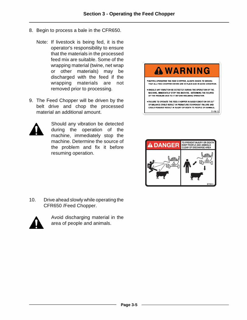
Note: If livestock is being fed, it is theoperator's responsibility to ensurethat the materials in the processedfeed mix are suitable. Some of thewrapping material (twine, net wrapor other materials) may bedischarged with the feed if thewrapping materials are notremoved prior to processing.
9. The Feed Chopper will be driven by thebelt drive and chop the processedmaterial an additional amount.
Should any vibration be detectedduring the operation of themachine, immediately stop themachine. Determine the source ofthe problem and fix it beforeresuming operation.
10. Drive ahead slowly while operating theCFR650 /Feed Chopper.
Avoid discharging material in thearea of people and animals.
Page 3-5

Section 3 - Operating the Feed Chopper
Operating Without the Feed Chopper
The CFR650 can be operated withoutadditional chopping of material.
Shut off the tractor engine andremove the key.
Wait for all components to stoprotating.
Do not place hands in the FeedChopper drive clutch area whilethe flail drum is turning. Contactwith the rotating large pulleyengaged to the rotating flail drumcan cause serious injury.
Page 3-6

Section 3 - Operating the Feed Chopper
1. Open the Drive Guard Door.
- Remove the rubber access door latch(1).
2. Pivot the drive guard door (2) to open thedrive clutch area.
3. Disengage the Feed Chopper drive.
- Push in the clutch pin and twist it 90degrees to release the roll pin fromthe lock plate.
- Twist the clutch pin until the springmoves the second roll pin through theslot (4)
- This will move the clutch pin out ofthe flail drum plate.
Remove Rubber Holder 201251C
Twist Clutch Pin to Disengage Drive 217157C
Open Guard Door 219059
Page 3-7

Section 3 - Operating the Feed Chopper
4. Pull the clutch pin (3) until the second rollpin has cleared the slot.
- Twist the clutch pin (3) until thesecond roll pin is resting against theclutch front plate.
5. Lower the Feed Chopper discharge doorto allow material to pass out of theCFR650 and over the Feed Chopper.
- See Section 2 - “Discharge DoorSetup For CFR650 Operation Only”for the instructions in this process.
6. Drive ahead slowly while operating theCFR650.
Avoid discharging material in thearea of people and animals.
Note: If livestock is being fed, it is theoperator's responsibility to ensurethat the materials in the processedfeed mix are suitable. Some of thewrapping material (twine, net wrapor other materials) may bedischarged with the feed if thewrapping materials are notremoved prior to processing.
Pull and Twist Pin to Lock 217156C
Lower Door to Pass Material Over Chopper 201242C2
Page 3-8

Section 3 - Operating the Feed Chopper
Unplugging the Feed Chopper
1. Reduce the engine speed to idle.
2. Disengage tractor power take off (PTO).
3. Set the tractor park brake.
Shut off tractor engine and removekey.
Wait for all components to stoprotating.
Do not place hands in the FeedChopper while the rotor is turning.Contact with the rotating knives willcause serious injury.
4. Disengage the Feed Chopper drive bymoving the clutch pin out and twisting itso the second roll pin is resting on theclutch front plate.
Do not place hands in the FeedChopper drive clutch area whilethe flail drum is turning. Contactwith the rotating large pulleyengaged to the rotating flail drumcan cause serious injury.
Disengage the Chopper Drive 217156
Page 3-9

Section 3 - Operating the Feed Chopper
5. Remove the discharge door to gainaccess to the chopper rotor and housing.
- Disconnect the discharge doorsupports by removing the hairpins andremoving the door from the supportholes.
- Remove the discharge door by slidingthe door hinge from the slots.
- Clear the chopping area and theknives.
- Replace the discharge door by sliding the door hinges into the slots.
- Connect the door support with thedoor front pin in the middle large hole and the small pin in the lowest smallhole labeled “C”.
- Fasten with the hairpin.
Disconnect Discharge Door Supports 201238
Remove Discharge Door 201237
Replace Door and Connect Door Supports 201240C2
Page 3-10

Section 4 - Maintaining the Feed Chopper
4.0 MAINTAINING THE FEED CHOPPER
Shut down the tractor and removethe key before repairing, servicing,lubricating or cleaning themachine.
Relieve all hydraulic pressure inthe hoses. Disconnect thehydraulic hoses from the tractor before going near the machine.
LubricationLubricate all grease fittings with a qualitylithium soap compatible E.P. grease meetingthe N.L.G.I. #2 specifications and containingno more than 1% molybdenum disulfide.
Every 10 Hours
! Lubricate rear rotor bearing.
- Access the grease point through thehole in the drive cover.
! Lubricate front rotor bearing.
Grease Front Rotor Bearing 201259C
Grease Rear Rotor Bearing 201258C
Page 4-1

Section 4 - Maintaining the Feed Chopper
Replace Knife Set & Opposite Set 218155C
Grease Flail Drum Bearing 201260C
Twine Cutter Access 201261C
Greasing the CFR650 Rear Flail DrumBearing (Every 50 hours)
! To access the CFR650 rear flail drumbearing:- Open the drive guard door.- Rotate the sheave to access the grease zerk on the bearing.
Twine Cutter Access! To access the twine cutter opening:
- Open the drive guard door.- Insert the twine cutter into the twine
cutter opening (1).
Knife Replacement
Replace knives that are broken or worn to thepoint that they will not process materialproperly.
Four knives must be replaced at the sametime.
Note: To maintain rotary balance, the set ofknives on the opposite side of therotor must be replaced at the sametime. (3)
- Remove the nut and bolt holding theknives.
- Discard the set of old knives, the boltand nut.
- Install the knives using the new boltand nut.
Page 4-2

Section 4 - Maintaining the Feed Chopper
Belt Tension Spring Adjustment 219058C
Belt Tension Adjustment
The belt tension adjuster has a spring tokeep the tension.
- The belt is tensioned from the factory.
To confirm adequate belt tension:- Check if the spring washer (1) is showing
in the cut out window (2). If it is showingin the window then the belt tension is inthe acceptable range.
To adjust belt tension:- If the spring washer (1) is not showing in
the cut out window (2) then adjust the belttension by:
- Loosening the jam nut (3) on thethreaded rod.
- Turn the nut (4) next to the springwasher to adjust the spring so itshows in the cut out window (2).
- Tighten the jam nut (3).
Rotor Twine Scraper Adjustment
Adjust the twine scrapers (3) on both ends ofthe rotor shaft.
- Loosen the bearing bolt nuts (4) thathave the twine scraper on it to allowthe bearing bolts to be loose.
Adjust Twine Scrapers on Rotor Shaft 218154C
Page 4-3

Section 4 - Maintaining the Feed Chopper
Note: On the rear shaft remove thesheave shield (2) to get access tothe bearing bolts.
- Slide the twine scraper (3) on thebearing bolts until it is almost touchingthe rotor shaft.- Do not have the scraper touching
the rotor shaft.- To ensure clearance, use a
flashlight to check for a visiblesliver of light between the edgeof the twine scraper and therotor shaft.
- Tighten the bearing bolt nuts (4) tofasten the scraper in place.- Torque to 65 lb-ft (88 Nm).
Note: On the rear shaft replace the outersheave shield and fasten in place.
Remove Rear Sheave Shield 201258C2
Adjust Twine Scrapers on Rotor Shaft 218154C
Page 4-4

Section 5 - Troubleshooting
5.0 TROUBLESHOOTING
Operation
Symptom Problem Solution
Excessive Rotor Vibration Broken knife. Replace knives in pairs.Also replace knife pair onopposite side of the rotor tomaintain rotational balance.
Missing knives. Replace knives in pairs.Also replace knife pair onopposite side of the rotor tomaintain rotational balance.
Foreign material lodged inchopper housing.
Remove foreign material.
Check condition of knives.Replace knives as pairs andalso replace knife pair onopposite side of rotor tomaintain rotational balance.
Check for damage to therotor. Contact Highline forproper repair procedure.
Failed rotor end bearing. Check if rotor rotation feelsrough. Replace failedbearing.
Check for rotor side play.Replace failed bearing.
Visually inspect bearing.Replace failed bearing.
Rotor Does Not Spin Drive clutch is not engaged. Twist the clutch pin to movethe roll pin into the slot.Rotate the large pulley untilthe drive pin snaps into aconnecting hole in the flaildrum plate. Push the clutchpin forward and twist to lockthe clutch pin.
Broken Belt. Replace the belt.
Page 5-1

Section 5 - Troubleshooting
Foreign material lodged inhousing.
Remove foreign material toallow rotor to spin freely.Check condition of knives.Replace knives as pairs andalso replace knife pair onopposite side of rotor tomaintain rotational balance.
Rotor bearing has seized. Check bearings or replace.
Rotor Stops Spinning Drive clutch pin has movedout and no longer isengaged with the flail drumplate.
Twist the clutch pin to movethe roll pin into the slot.Rotate the large pulley untilthe drive pin snaps into aconnecting hole in the flaildrum plate. Push the clutchpin forward and twist to lockthe clutch pin.
Belt has come off thesheaves or tensioner.
Place the belt on thesheaves and the tensioner.Check the alignment of thesheaves and tensioner.Adjust if needed.
Broken belt. Replace the belt.
Drive Belt Loose Belt Tension not in range Adjust the spring tensioner.See Section 4 forinformation on adjusting thebelt tension.
Belt has stretched. Replace the belt.
Adjust the spring tensioner.See Section 4 forinformation on adjusting thebelt tension.
Page 5-2
Highline New Equipment Limited Warranty PolicyOne (1) Year / 12 Months - Parts and Labour
Highline Mfg. Ltd. (hereinafter "Highline") warrants this new product of Highline's manufacturer to be free fromdefects in material and workmanship, under normal use and service for one (1) full year after initial purchase/retailsale. Highline will warrant its product for one (1) year parts and labour, if performed by a qualified Dealer. ThisLimited Warranty shall apply only to complete machines of Highline's manufacture. Parts are covered by a separateLimited Warranty.
EQUIPMENT AND ACCESSORIES NOT OF HIGHLINE'S MANUFAC TURE ARE WARRANTED ONLY TO THEEXTENT OF THE ORIGINAL MANUFACTURER'S WARRANTY AND SUBJECT TO THEIR ALLOWANCE TOHIGHLINE ONLY IF FOUND DEFECTIVE BY SUCH MANUFACTUR ER.
During the Limited Warranty period specified above, any defect in material or workmanship in any warranted itemof Highline Equipment not excluded below shall be repaired or replaced at Highline's option without charge by anyauthorized independent Highline Dealer. An authorized Dealer must make the warranty repair or replacement.Labour in accordance with Highline's labour reimbursement policy. Highline reserves the right to supplyremanufactured replacement parts as it deems appropriate.
RETAIL PURCHASER RESPONSIBILITYThis Limited Warranty requires proper maintenance and periodic inspections of the Equipment as indicated in theOperator's Manual furnished with each new Equipment. The cost of routine or required maintenance and servicesis the responsibility of the retail purchaser. The retail purchaser is required to keep documented evidence that theseservices were performed. This Highline New Equipment Limited Warranty may be subject to cancellation if the aboverequirements are not performed.
EXCLUSIONS AND LIMITATIONSThe warranties contained herein shall NOT APPLY TO:1. Any defect which was caused (in Highline's sole judgement) by other than normal use and service of the
Equipment, or by any of the following:a. accident b. misuse or negligence c. overloading d. of reasonable and proper maintenance e. improper repair or installation f. unsuitable storage g. non-Highline approved alteration or modification h. natural calamities i. vandalism j. parts or accessories installed on Equipment which were not manufactured or installed by Highline authorized
Dealersk. the elements l. collision or other accident.
2. Any Equipment whose identification numbers or marks have been altered or removed.3. Any Equipment which any of the required or recommended periodic inspection or services have been performed
using parts not manufactured or supplied by Highline or meeting Highline Specifications including, but withoutlimitation, lubricants (oil, grease), belt lacings, and hydraulic fluids.
4. Any Equipment used in demonstrations not performed by a Highline Dealer. Warranty will be at the discretionof Highline for all other demonstration warranty.
5. New Equipment delivered to the retail purchaser in which the warranty registration has not been completed andreturned to Highline within thirty (30) days from the date of purchase.
6. Any defect that was caused (in Highline's sole judgement) by operation of the Equipment not abiding by standardoperating procedures outlined in the Operator's Manual.
7. Tire Limited Warranties and support are the responsibility of the respective product's manufacturer.8. Transportation costs, if any, of transporting to the Highline Dealer.9. In no event shall Highline's liability exceed the purchase price of the product.10. Highline shall not be liable to any person under any circumstances for any incidental or consequential damages
(including but not limited to, loss of profits, out of service time and damage to equipment which this equipmentmay be attached) occurring for any reason at any time.
11. Diagnostic and overtime labour premiums are not covered under this Limited Warranty Policy.
Rev 3.2

12. Depreciation damage caused by normal wear, lack of reasonable and proper maintenance, failure to followoperating instructions, misuse, and/or lack of proper protection during storage.
13. Accessory systems and electronics not of Highline's manufacture are warranted only to the extent of suchmanufacturer's respective Limited Warranty if any.
14. Wear items which are listed by product group below:
COMMON WEAR ITEMSRoller chain, sprockets, clutches, shear bolts, clutch components, chains, gearbox housings bolts/torqued parts,flails, feed roller belting, coupler chain, DRV couplers, bogie wheels, apron tines and hoses, blades and blade pans,blade bolts and nuts, skid shoes, chain guards, clutches and clutch components.
PARTS WARRANTYParts replaced in the warranty period will receive the balance of the one year New Equipment Limited Warranty.Replacement parts after the original machine warranty are warranted to be free from defects of material for ninety(90) days or the part will be repaired or replaced, without labour coverage for removal and reinstallation.
EXCLUSION OF WARRANTIESUNLESS OTHERWISE REQUIRED BY LAW, AND EXCEPT FOR THE WARRANTIES EXPRESSLY ANDSPECIFICALLY MADE HEREIN, HIGHLINE MAKES NO OTHER WARRANTIES, AND ANY POSSIBLE LIABILITYOF HIGHLINE HEREIN UNDER IS IN LIEU OF ALL OTHER WARRANTIES, EXPRESS, IMPLIED, ORSTATUTORY, INCLUDING, BUT NOT LIMITED TO, ANY WARRANTIES OF MERCHANT ABILITY OR FITNESSFOR A PARTICULAR PURPOSE. HIGHLINE RESERVES THE RIGHT TO MODIFY, ALTER AND IMPROVE ANYPRODUCT WITHOUT INCURRING ANY OBLIGATION TO REPLACE ANY PRODUCT PREVIOUSLY SOLD WITHSUCH MODIFICATION. NO PERSON IS AUTHORIZED TO GIVE ANY OTHER WARRANTY, OR TO ASSUMEANY ADDITIONAL OBLIGATION ON HIGHLINE'S BEHALF.
Rev 3.2