c:/documents and settings/farid/desktop/thesis/latex/main
TRANSCRIPT
Alma Mater Studiorum - Universita di Bologna
DOTTORATO DI RICERCA IN
Meccanica e Scienze Avanzate dell’Ingegneria
Ciclo XXVI
Settore Concorsuale di afferenza: 09/A2
Settore Scientifico disciplinare: ING-IND/13
DESIGN AND CHARACTERIZATION OF CURVED
AND SPHERICAL FLEXURE HINGES FOR PLANAR
AND SPATIAL COMPLIANT MECHANISMS
Presentata da:Ing. Farid Parvari Rad
Coordinatore Dottorato: Relatori:
Prof. Vincenzo Parenti Castelli Prof. Vincenzo Parenti Castelli
Dott. Giovanni Berselli
Esame finale anno 2014

2

To my dear parents
and my lovely family
without whom I would never have been able to fulfill this dissertation.

4
Abstract
A flexure hinge is a flexible connector that can provide a limited rotational motionbetween two
rigid parts by means of material deformation. These connectors can be used to substitute tradi-
tional kinematic pairs (like bearing couplings) in rigid-body mechanisms. Whencompared to their
rigid-body counterpart, flexure hinges are characterized by reduced weight, absence of backlash
and friction, part-count reduction, but restricted range of motion. There are several types of flexure
hinges in the literature that have been studied and characterized for different applications. In our
study, we have introduced new types of flexures with curved structuresi.e. circularly curved-beam
flexures and spherical flexures. These flexures have been utilized for both planar applications
(e.g. articulated robotic fingers) and spatial applications (e.g. sphericalcompliant mechanisms).
We have derived closed-form compliance equations for both circularly curved-beam flexures and
spherical flexures. Each element of the spatial compliance matrix is analytically computed as a
function of hinge dimensions and employed material. The theoretical model is then validated by
comparing analytical data with the results obtained through Finite Element Analysis. A case study
is also presented for each class of flexures, concerning the potential applications in the optimal
design of planar and spatial compliant mechanisms. Each case study is followed by comparing the
performance of these novel flexures with the performance of commonly used geometries in terms
of principle compliance factors, parasitic motions and maximum stress demands.Furthermore,
we have extended our study to the design and analysis of serial and parallel compliant mecha-
nisms, where the proposed flexures have been employed to achieve spatial motions e.g. compliant
spherical joints.

6

Contents
1 Introduction and Thesis Outline 15
1.1 Introduction to Compliant Mechanisms . . . . . . . . . . . . . . . . . . . . . . 15
1.2 Advantages . . . . . . . . . . . . . . . . . . . . . . . . . . . . . . . . . . . . . 16
1.3 Challenges . . . . . . . . . . . . . . . . . . . . . . . . . . . . . . . . . . . . . . 18
1.4 Motivation . . . . . . . . . . . . . . . . . . . . . . . . . . . . . . . . . . . . . . 18
1.5 Contribution . . . . . . . . . . . . . . . . . . . . . . . . . . . . . . . . . . . . . 20
1.6 Thesis outline . . . . . . . . . . . . . . . . . . . . . . . . . . . . . . . . . . . . 20
2 Background and Literature 23
2.1 Flexure Hinges . . . . . . . . . . . . . . . . . . . . . . . . . . . . . . . . . . . 23
2.2 Pseudo-Rigid-Body Model . . . . . . . . . . . . . . . . . . . . . . . . . . . . .24
2.3 Compliance-Based Design of Flexure Hinges . . . . . . . . . . . . . . . . . .. 25
3 Design and Characterization of Circularly Curved-Beam Flexure Hinges for Planar
Compliant Mechanisms 29
3.1 Introduction . . . . . . . . . . . . . . . . . . . . . . . . . . . . . . . . . . . . . 29
3.2 General Approach for Deriving Compliance Equations of Cantilever Curved Beams 30
3.3 Evaluating the Spatial Compliance of Circularly Curved-Beam Flexures .. . . . 33
3.4 Numerical Example and Model Validation . . . . . . . . . . . . . . . . . . . . . 35
4 Design and Characterization of Spherical Flexure Hinges for Spatial Compliant Mech-
anisms 39
4.1 Introduction . . . . . . . . . . . . . . . . . . . . . . . . . . . . . . . . . . . . . 39
4.2 Closed-Form Compliance Equations for Spherical Flexure Hinges . . .. . . . . 40
4.3 Defining Cross Section Properties for the Spherical Flexure . . . . . .. . . . . 41
4.4 Stress Considerations . . . . . . . . . . . . . . . . . . . . . . . . . . . . . . . . 43
4.5 Numerical Example and Model Validation . . . . . . . . . . . . . . . . . . . . . 44
8 CONTENTS
5 Compliance-Based Evaluation of a Fully Compliant Spherical Chain withTwo De-
grees of Freedom 49
5.1 Introduction . . . . . . . . . . . . . . . . . . . . . . . . . . . . . . . . . . . . . 49
5.2 Closed-Form Compliance Equations for a Serial 2-SF Spherical Chain. . . . . . 51
5.3 Numerical Example and Model Validation . . . . . . . . . . . . . . . . . . . . . 52
6 Design and Analysis of a Fully Compliant Passive Spherical Joint UsingSpherical
Flexure Hinges 57
6.1 Introduction . . . . . . . . . . . . . . . . . . . . . . . . . . . . . . . . . . . . . 57
6.2 Closed-Form Compliance Equations for the Spherical Joint . . . . . . . .. . . . 58
6.3 Numerical Example and Model Validation . . . . . . . . . . . . . . . . . . . . . 61
7 Conclusion 67

List of Abbreviations
MEMS Micro Electromechanical Systems
FCM Flexure-Based Compliant Mechanism
FEA Finite Element Analysis
PRBM Pseudo-Rigid-Body Model
SBF Straight Beam Flexure
CCBF Circularly Curved-Beam Flexure
SF Spherical Flexure

10 CONTENTS

List of Figures
1.1 The bow and arrow . . . . . . . . . . . . . . . . . . . . . . . . . . . . . . . . . 16
1.2 Greek palintone: A torsion-powered catapult . . . . . . . . . . . . . . . . .. . . 16
1.3 Commonly used compliant devices: Binder clips, paper clips, hair clips, backpack
latch, eyelash curlers and nail clippers . . . . . . . . . . . . . . . . . . . . . . .17
1.4 Pulley-based articulated robotic finger [6] . . . . . . . . . . . . . . . . . . .. . 19
1.5 FCM-based articulated robotic finger [6] . . . . . . . . . . . . . . . . . . . .. . 19
2.1 (a) Conventional rigid-body joint (b) Flexure hinge . . . . . . . . . . . .. . . . 24
2.2 (a) A small-length flexural pivot (b) Its pseudo-rigid-body model . .. . . . . . 25
2.3 Straight beam flexure loaded at the free end . . . . . . . . . . . . . . . . .. . . 26
2.4 Different type of flexures . . . . . . . . . . . . . . . . . . . . . . . . . . . . .. 28
3.1 Mono-piece robotic finger employing SBFs [26] . . . . . . . . . . . . . . . .. . 30
3.2 Mono-piece robotic finger employing CCBFs [26] . . . . . . . . . . . . . . .. . 30
3.3 Cantilever curved beam loaded at the free end . . . . . . . . . . . . . . . .. . . 31
3.4 Geometric parameters of the CCBF . . . . . . . . . . . . . . . . . . . . . . . . 33
3.5 Cross section properties of the CCBF . . . . . . . . . . . . . . . . . . . . . . .33
3.6 FEA of the CCBF . . . . . . . . . . . . . . . . . . . . . . . . . . . . . . . . . . 35
3.7 3D bar representation for the compliance matrix of the CCBF . . . . . . . . . .. 37
3.8 3D bar representation for the compliance matrix of the SBF . . . . . . . . . . .. 37
3.9 Comparison of the maximum achievable rotation,αCCBF/
αSBF , as a function of
the CCBF radius,R, and thickness,t. . . . . . . . . . . . . . . . . . . . . . . . . 38
4.1 Geometric parameters of the SF . . . . . . . . . . . . . . . . . . . . . . . . . . 40
4.2 Cross section properties of the SF . . . . . . . . . . . . . . . . . . . . . . . . .42
4.3 FEA of the SF . . . . . . . . . . . . . . . . . . . . . . . . . . . . . . . . . . . . 45
4.4 Influence of varyingR on compliance ratios . . . . . . . . . . . . . . . . . . . . 46
4.5 Influence of varyingθ on compliance ratios . . . . . . . . . . . . . . . . . . . . 47
4.6 Influence of varyingθ on stress ratio . . . . . . . . . . . . . . . . . . . . . . . . 47

12 LIST OF FIGURES
5.1 SF-based compliant chain . . . . . . . . . . . . . . . . . . . . . . . . . . . . . . 50
5.2 SBF-based compliant chain . . . . . . . . . . . . . . . . . . . . . . . . . . . . . 50
5.3 Influence of varyingδ on principal compliances . . . . . . . . . . . . . . . . . . 53
5.4 Finite element model of the 2-SF chain. . . . . . . . . . . . . . . . . . . . . . . 54
5.5 Finite element model of the 2-SBF chain. . . . . . . . . . . . . . . . . . . . . . 54
5.6 Influence of varyingθ on compliance ratios . . . . . . . . . . . . . . . . . . . . 55
6.1 Compliant spherical joints . . . . . . . . . . . . . . . . . . . . . . . . . . . . . 58
6.2 Compliant spherical joint composed of two spherical chains . . . . . . . .. . . 59
6.3 3D bar representation for the SF-Chain compliance matrix . . . . . . . . . . .. 65
6.4 3D bar representation for the SBF-Chain compliance matrix . . . . . . . . . .. 65
6.5 Maximum von Mises stress for the SF along its axis . . . . . . . . . . . . . . . . 66

List of Tables
3.1 Compliance factors for the cantilever curved beam loaded at the free end . . . . . 33
3.2 Compliance factors for the CCBF loaded at the free end . . . . . . . . . . .. . . 34
3.3 Compliance factors for the CCBF and comparison between analytical andFEA
results . . . . . . . . . . . . . . . . . . . . . . . . . . . . . . . . . . . . . . . . 36
4.1 Compliance factors for the SF loaded at the free end . . . . . . . . . . . . .. . . 41
4.2 Compliance factors for the SF and comparison between analytical and FEA results 45
4.3 Compliance factors for the similar CCBF . . . . . . . . . . . . . . . . . . . . . 46
5.1 Compliance elements of the mechanism . . . . . . . . . . . . . . . . . . . . . . 52
5.2 Compliance elements of the 2-SF spherical chain and comparison betweenanalyt-
ical and FEA results . . . . . . . . . . . . . . . . . . . . . . . . . . . . . . . . . 53
5.3 Compliance elements of the 2-SBF spherical chain . . . . . . . . . . . . . . . .54
6.1 Compliance factors for the two spherical chains . . . . . . . . . . . . . . . .. . 61
6.2 Compliance elements for Chain#1 and comparison between analytical and FEA
results . . . . . . . . . . . . . . . . . . . . . . . . . . . . . . . . . . . . . . . . 62
6.3 Compliance elements for Chain#2 and comparison between analytical and FEA
results . . . . . . . . . . . . . . . . . . . . . . . . . . . . . . . . . . . . . . . . 62
6.4 Compliance elements for the SBF-Chain . . . . . . . . . . . . . . . . . . . . . . 64

14 LIST OF TABLES
Chapter 1
Introduction and Thesis Outline
This chapter briefly introduces compliant mechanisms, their advantages anddisad-vantages in comparison with ordinary mechanisms and explains their contributionsin different fields of mechanical and precision engineering. The motivationandoutline of this thesis is further described.
1.1 Introduction to Compliant Mechanisms
A mechanism is a mechanical part or combination of parts that transforms inputloads and motions
into a desired set of output motions. A mechanism is commonly modeled as a set ofinterconnected
rigid links by means of ideal rigid joints (kinematic pairs) which provide relativemovements be-
tween the rigid links. Kinematic pairs ideally constrain the relative motion between rigid links
i.e. constraining the pure rotational motion about a single point, or prismatic motionto a line,
thus prevent any undesired motion produced from deflections and elasticdeformations. When the
flexibility and elastic deformations are used to provide desired relative motions, we meet a new
class of mechanisms called compliant mechanisms. Compliant mechanisms gain their mobility by
transforming an input force or energy into an output motion, undergoing an elastic deformation,
due to the existence of flexible members in these mechanisms. The concept of using compliant
members dates back to the late Paleolithic (about 35000 to 8000 B.C.) [1] when archery seems to
have been invented by the late stone-age humans for war and hunting purposes (Fig. 1.1). Pulling
the arrow, strain energy is stored in the arc and by releasing the arc, it is transformed to kinetic en-
ergy of the arrow creating the output motion. Strain energy is the same as elastic potential energy
that is stored in a spring. This concept has been extended to use in more heavier weapons later, i.e.
catapults that first used by Syracusean Greeks in 399 B.C. [2]. Catapults were the artillery of the

16 Introduction and Thesis Outline
Figure 1.1: The bow and arrow Figure 1.2: Greek palintone: A
torsion-powered catapult
ancient armies to hurl heavy objects or arrows over a large distance in early battles for winning the
war. A Greek ”Palintone” type ballista catapult is shown in Fig. 1.2. It was capable of throwing a
three pound concrete ball more than 200 yards [3]. Palintone is called a torsion-powered catapult
since strain energy is provided by using tightly string coils of rope like a torsional spring.
The use of compliant members were limited mostly for war machines until the last century. Re-
cently, compliant mechanisms become important components for various applications in different
research areas such as micro-electromechanical systems (MEMS), robotics, precision engineering,
biomechanics, etc. They are also used frequently in our daily life. Some of the most commonly
used compliant mechanisms are shown in Fig. 1.3.
1.2 Advantages
Compliant mechanisms encompass several advantages in comparison with kinematic pairs that
make them suitable for a wide range of applications. These advantages canbe classified as fol-
lows [4]:
• Single Layer Fabrication: Compliant mechanisms can be made from a single layer of ma-
terial. This makes them compatible with different fabrication methods available for MEMS,
such as surface micromachining, bulk micromachining and the LIGA (Lithographie or lithogra-
phy/Galvanoformung or electroforming/Abformung or molding) process using a compact syn-
chrotron radiation (SR) source [5].

1.2 Advantages 17
Figure 1.3: Commonly used compliant devices: Binder clips, paper clips, hairclips, backpack
latch, eyelash curlers and nail clippers
• No Need for Assembly:Fully compliant mechanisms that gain all of their motion from the de-
flection of flexible members are usually fabricated in a single piece and do notrequire assembly
of different components.
• Compactness:Some compliant mechanisms can be manufactured in a compact form, making
them ideal for micro-scale and precision engineering applications.
• No Friction Losses: Considering the fact that compliant mechanisms gain their motion from
deflection of flexible members rather than rigid body joints, the friction relevant to rubbing sur-
faces can be removed. This eliminates the need for lubrication and reduceswear.
• Absence of Wear: Wear is the erosion caused by physical interactions between contacting
surfaces and occurs in kinematic pairs. It can be particularly problematic for small range ap-
plications in biomechanics and precision mechanisms. Wear can be removed byeliminating
friction between contacting surfaces. This will increase the life cycles of mechanical systems.
• No Need for Lubrication: Absence of friction losses in compliant mechanisms, eliminates the
need for lubrication. This could have a significant role in applications that suffer an easy lubri-

18 Introduction and Thesis Outline
cation process.
• High Accuracy: The absence of friction and wear, as described above, along with the backlash-
free motion inherent in compliant mechanisms, increase their precision and make them prefer-
able to use in high accuracy instruments.
• High Reliability: The aforementioned characteristics of compliant mechanisms, their light
weight and reduced maintenance result in high reliability.
1.3 Challenges
Despite all the advantages that compliant mechanisms comprise in comparison withordinary
mechanisms, they also have some challenges:
• Limited Range of Motion: Since the relative motion between rigid parts is provided by means
of material deformation, compliant mechanisms are unable to undergo continuous motions and
are capable of providing limited range of motion.
• Parasitic Motions: The relative motion provided by compliant mechanisms is not a pure mo-
tion and there are always secondary undesired motions produced by thecomplex deformation
behavior of these mechanisms. The secondary undesired motions are called parasitic motions.
• Nonlinear Motions: Some compliant mechanisms require to undergo large deformations where
linearized beam equations are no longer valid. Nonlinear equations that account for the geo-
metric nonlinearities caused by large deflections must be used. This can maketheir design and
analysis more complicated.
• Fatigue Failures: Most compliant mechanisms need to undergo repeated loading and to operate
under cyclic stress conditions which make them vulnerable to fatigue failures.
1.4 Motivation
As previously described, compliant mechanisms gain their mobility from the deflection of flex-
ible members. These flexible members are called flexure hinges. A flexure hinge, is a flexible
and slender region between two rigid parts that can provide a relative rotation between the rigid
parts by means of material deformation. They can be usually obtained by machining a blank
piece of material, thus obtaining the so-called Flexure-Based Compliant Mechanisms (FCMs) in
which compliance is concentrated within the relatively small regions of the flexures. FCMs are

1.4 Motivation 19
Figure 1.4: Pulley-based articulated robotic
finger [6]
Figure 1.5: FCM-based articulated robotic
finger [6]
widely used in different research areas considering their wide advantages over traditional rigid-
body mechanisms. Some examples of implementing FCMs in different fields are translation micro-
positioning stages, piezoelectric actuators and motors, high-accuracy alignment devices for optical
fibers, missile-control devices, displacement and force amplifiers/deamplifiers, orthotic prosthe-
ses, antennas, valves, scanning tunneling microscopes, accelerometers, gyroscopes, high-precision
cameras, nano-lithography, robotic micro-displacement mechanisms, nano-scale bioengineering,
small-scale insect-like walking robots, actuation devices for unmanned micro aerial vehicles, or
nano-imprint technology.
The main focus of this study is on designing and developing FCMs for possibleapplications par-
ticularly in areas as mechanical and precision engineering, robotics, andbiomedical engineering.
For instance, Fig. 1.4 shows an articulated robotic finger for applications inanthropomorphic
robotic hands. Anthropomorphic robotic hands have been widely studied because of their inherent
similarity to the human hand and their contribution in various fields ranges from hand prosthet-
ics to healthcare robots and robotic surgeries to space explorations. However, it has been always
difficult to mimic the human hand due to its unique biological features and kinematic behavior.
Thus, robotic hands often require complicated joint mechanism such as hinges, linkages, pulleys,
belts and sensors to be designed and developed in a small space in order toachieve the complex
behavior of the human hand.
From a design perspective, the introduction of FCMs in serial articulated chains, like anthropo-
morphic hands and prosthesis, seems promising as it can allow the generationof very slender and
light mechanisms that better reproduce biological structures with a reducednumber of parts, easy
to be manufactured and assembled, cheap and compatible with the required features. The example
of such an articulated robotic finger is shown in Fig. 1.5.

20 Introduction and Thesis Outline
1.5 Contribution
The main contribution of this thesis is to design and characterize new types of flexure hinges with
curved centroidal axes for both planar and spatial applications. First, Circularly Curved-Beam
Flexures (CCBFs) will be characterized and particularly designed for planar applications such as
articulated robotic fingers. The spatial compliance of these flexures will beevaluated and their
closed-form compliance equations will be derived. Spherical Flexures(SFs) will be then intro-
duced and specifically designed for spatial applications. These flexures will be evaluated concern-
ing their capabilities in generating spherical motions and they will be used in compliant spherical
chains (in particular, for the design of a new compliant spherical joint). Further evaluations will
be carried out to compare the main characteristics of the aforementioned flexures with commonly
used flexure hinges.
1.6 Thesis outline
• Chapter 1 briefly introduces compliant mechanisms, their advantages and disadvantages in com-
parison with ordinary mechanisms and explains their contributions in different fields of mechan-
ical and precision engineering. The motivation and outline of this thesis is further described in
this chapter.
• Chapter 2 is dedicated to a brief presentation of flexure hinges which are the main components
of flexure-based compliant mechanisms. Flexure hinges provide the relative motion between
the adjoining rigid parts by means of elastic deformation. The common methods used for de-
signing and analyzing flexure hinges accompanied by their literature revieware described in
this chapter.
• In Chapter 3, the closed-form compliance equations for circularly curved-beam flexures are de-
rived. Following a general modeling procedure, each element of the spatial compliance matrix is
analytically computed as a function of both hinge dimensions and employed material. The the-
oretical model is then validated by comparing analytical data with the results obtained through
finite element analysis. Finally, a case study is presented concerning the potential application
of these types of flexures in the optimal design of compliant robotic fingers.
• In Chapter 4, the closed-form compliance equations for spherical flexures are derived. Each
element of the spatial compliance matrix is analytically computed as a function of both hinge
dimensions and employed material. The theoretical model is then validated by relating an-
alytical data with the results obtained through finite element analysis. Finally, for a generic
loading condition, spherical flexures are compared to circularly curved-beam flexures in terms
of secondary compliance factors and maximum stress.
• Chapter 5 introduces and investigates a fully compliant spherical chain thatis obtained by the in-
series connection of two identical primitive spherical flexures with coincident center of spherical

1.6 Thesis outline 21
motion. The compliance matrix of the proposed chain is obtained via an analyticalprocedure
and validated via finite element analysis. Comparison with an equivalent fully compliant chain
employing straight beam flexures is also provided to highlight the added benefits when using
primitive spherical flexures.
• Chapter 6 represents a new type of passive compliant spherical joint. The joint is made by the
in-parallel connection of two fully compliant spherical chains. Each chainis composed of three
identical spherical flexures connected in-series with mutually orthogonalaxes. The closed-form
compliance equations for the spherical joint are derived via the previously described analytical
method. The compliant spherical chain is also evaluated comparing with the equivalent compli-
ant serial chain employing straight beam flexures.
• Chapter 7 summarizes the main contributions of this thesis.

22 Introduction and Thesis Outline

Chapter 2
Background and Literature
This chapter is dedicated to a brief presentation of flexure hinges which are themain components of flexure-based compliant mechanisms. Flexure hinges providethe relative motion between the adjoining rigid parts by means of elastic defor-mation. The common methods used for designing and analyzing flexure hingesaccompanied by their literature review are described in this chapter.
2.1 Flexure Hinges
A flexure hinge is a slender flexible connector that provides the relative rotational motion between
two adjacent rigid members via material deformation rather than by the sliding or rolling of mating
surfaces (Fig. 2.1). The flexure hinge is also called as ”flexural pivot” or simply ”flexure”. When
compared to their rigid-body counterparts, flexure hinges are characterized by reduced weight, ab-
sence of backlash and friction, one-piece manufacturing with no need ofassembling (i.e. reduced
production costs), but restricted range of motion.
Flexure hinges can be classified as single-axis, two-axis and multi-axis flexures [7]. Single-axis
flexure hinges are supposed to be compliant with respect to one single axis(compliant or sensi-
tive axis) and stiff as much as possible about all other axes. Single-axis flexures are designed for
two-dimensional applications that have a planar motion and they can be fabricated by removing
material from a blank piece using manufacturing processes such as end-milling, electrodischarge
machining (EDM), laser cutting, metal stamping, or photolithographic techniques for MEMS.
Two- and multi-axis flexure hinges possess two or more compliant axes and are suitable for three-
dimensional applications with spatial motions. They can be usually machined by lathe-turning or
precision casting.

24 Background and Literature
Rigid links Rigid links
Rotational joint Flexure hinge
(a) (b)
Figure 2.1: (a) Conventional rigid-body joint (b) Flexure hinge
Although flexure hinges provide monolithic connections with no backlash andhysteresis, they
usually bring the following disadvantages: limited range of motion, parasitic motions and stress
concentrations. For this reason, to be effective, flexure hinges needto be conceived and optimized
for the specific application at hand. However it is not always straight forward to study and analyze
flexure hinges to achieve design demands for different applications. Analytical methods provide
accurate and precise means of evaluating and designing flexure hinges but they can be complicated
when flexures infold complex geometrical shapes or deforming out of linearized beam theory ap-
proximation. Finite Element Analysis (FEA) and simplified analytical methods such as Pseudo-
Rigid-Body Model (PRBM) are also efficient tools that can be utilized to tackle such difficulties.
In the following of this chapter, the available techniques on designing and characterizing flexure
hinges, are briefly reviewed.
2.2 Pseudo-Rigid-Body Model
The PRBM is a tool that connects rigid-body mechanism theory to compliant mechanism theory
and provides the possibility of using traditional rigid-body modeling methods in the design and
analysis of compliant mechanisms. The PRBM principally treats flexures as rigid links connected
at appropriately placed pins, with torsional springs to represent the compliance behavior of flexible
members that undergo large and nonlinear deflections. Several works have been dedicated to study
and develop the PRBM for applications both in macro-scale range( [4], [8], [9], [10], [11], [12]
and etc.) and MEMS( [13], [14], [15], [16] and etc.).
Let us consider a small-length flexural pivot [9] shown in Fig. 2.2. Whenthe length of the flexural
pivot (l) is much smaller than the length of the rigid part (L), and the flexural pivot is much less
stiffer than the rigid part, the motion of the system can be modeled by a pin joint connecting two

2.3 Compliance-Based Design of Flexure Hinges 25
Ll l L
l/2
(a) (b)
Characteristic
pivot
Torsional
spring
r
Flexural
pivot
MM
MM
Figure 2.2: (a) A small-length flexural pivot (b) Its pseudo-rigid-bodymodel
rigid links, called as ”the characteristic pivot”. The characteristic pivot islocated at the center of
the flexural pivot and the length of the pseudo-rigid link,r, is defined as follows:
r = L+l2
(2.1)
The elastic deformation of the flexural pivot is modeled by a torsional spring with the spring
constantK:
K =EIl
(2.2)
whereE, is the material Young’s modulus andI is the second moment of area.
The PRBM can be extended to other segments such as fixed-guided flexiblesegments, pinned-
pinned segments, beams loaded with a moment at the end, and beams with followerloads. Com-
plete details for pseudo-rigid-body modeling of different types of segments can be found in [4].
2.3 Compliance-Based Design of Flexure Hinges
In spite of the fact that the PRBM is an exclusive tool in modeling and designing FCMs, it can
suffer from some limitations. First, torsional springs are incapable of modeling axial and lateral de-
formations resulting from axial and transversal forces that usually exist in loading flexure hinges.
Second, there are several FCMs that are intended to operate in small-displacement range, pro-
ducing small levels of output motion within acceptable levels of stress, where large-displacement
theory does not apply. Compliance-based design of flexure hinges canovercome such difficulties.
26 Background and Literature
xp
zp
yp
w
Op
Fixed
end Free
end
l
Sp
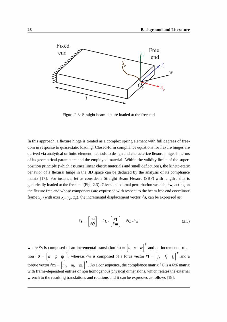
Figure 2.3: Straight beam flexure loaded at the free end
In this approach, a flexure hinge is treated as a complex spring element with full degrees of free-
dom in response to quasi-static loading. Closed-form compliance equationsfor flexure hinges are
derived via analytical or finite element methods to design and characterize flexure hinges in terms
of its geometrical parameters and the employed material. Within the validity limits of the super-
position principle (which assumes linear elastic materials and small deflections), the kineto-static
behavior of a flexural hinge in the 3D space can be deduced by the analysis of its compliance
matrix [17]. For instance, let us consider a Straight Beam Flexure (SBF)with length l that is
generically loaded at the free end (Fig. 2.3). Given an external perturbation wrench,pw, acting on
the flexure free end whose components are expressed with respect to the beam free end coordinate
frameSp (with axesxp, yp, zp), the incremental displacement vector,ps, can be expressed as:
ps=[
pupθθθ
]= pC ·
[pf
pm
]= pC · pw (2.3)
whereps is composed of an incremental translationpu =[u v w
]Tand an incremental rota-
tion pθ =[α φ ψ
]T, whereaspw is composed of a force vectorpf =
[fx fy fz
]Tand a
torque vectorpm =[mx my mz
]T. As a consequence, the compliance matrixpC is a 6x6 matrix
with frame-dependent entries of non homogenous physical dimensions, which relates the external
wrench to the resulting translations and rotations and it can be expresses as follows [18]:

2.3 Compliance-Based Design of Flexure Hinges 27
pC =
lEA 0 0 0 0 0
0 l3
3EIy0 0 0 l2
2EIy
0 0 l3
3EIx0 − l2
2EIx0
0 0 0 lGJ 0 0
0 0 − l2
2EIx0 l
EIx0
0 l2
2EIy0 0 0 l
EIy
(2.4)
whereA, Ix, Iy, J, E andG are respectively cross section area, principal and polar moments of
inertia of the beams cross section, Youngs modulus and shear modulus of theemployed material.
In this scenario, the knowledge of the hinge compliance behavior, even in the small displacement
range, can be extremely useful both for comparison purposes and forfirst-attempt sizing the hinge
dimensions. Closed-form compliance equations provide useful means to evaluate flexure hinges
on different basis i.e. principle compliance factors, sensitivity to undesired or parasitic motions
and maximum stress levels. Several studies have been proposed to designand characterize flexure
hinges on this basis. For instance, Paros and Weisbord [19] represented circular flexure hinges
(Fig. 2.4(a)) and provided compliance equations for them. Zettl et al. [20]performed FEA to
model right-circular flexure hinges. Xu and King [21] used this techniquefor investigating the
performance of elliptical (Fig. 2.4(b)) and corner-filleted flexure hinges (Fig. 2.4(c)). Lobontiu et
al. [22] represented the equations for corner-filleted flexure hinges using the Castigliano’s second
theorem. Schotborgh et al. [23] applied FEA to present dimensionless design graphs for three typ-
ical circular, corner-filleted and cross flexure hinges (Fig. 2.4(d)) inorder to provide a reasonable
comparison between them for design purposes. Tian et al [24] used numerical methods for dimen-
sionless graph analysis of three filleted V-shaped (Fig. 2.4(e)), cycloidal (Fig. 2.4(f)) and circular
flexure hinges. Chen et al. [25] obtained analytical equations for elliptical-arc-fillet flexure hinges.
In this thesis, we have introduced new types of flexure hinges with curvedaxes i.e. CCBFs (Fig.
2.4(g)) and SFs (Fig. 2.4(h)) for both planar applications like articulated robotic fingers and spatial
applications such as compliant spherical mechanisms. All the closed-form compliance equations
for these flexures are derived and represented as a function of the hinge geometric parameters
and employed material. Further analysis have been carried out to evaluate the performance of the
proposed flexures with commonly used ones such as SBFs.

28 Background and Literature
(a) Circular flexures (b) Elliptical flexures
(c) Corner-filleted flexures (d) Cross flexures
(e) Filleted V-shaped flexures (f) Cycloidal flexures
(g) Circularly curved-beam flexures (h) Spherical flexures
Figure 2.4: Different types of flexures

Chapter 3
Design and Characterization of
Circularly Curved-Beam Flexure
Hinges for Planar Compliant
Mechanisms
In this chapter, the closed-form compliance equations for circularly curved-beamflexures are derived. Following a general modeling procedure, eachelement ofthe spatial compliance matrix is analytically computed as a function of both hingedimensions and employed material. The theoretical model is then validated bycomparing analytical data with the results obtained through finite element analysis.Finally, a case study is presented concerning the potential application of these typesof flexures in the optimal design of compliant robotic fingers.
3.1 Introduction
As described earlier, flexure hinges have found a wide range of applications in different fields
such as serial articulated chains, like anthropomorphic hands and prosthesis. For instance, Fig.
3.1 and Fig. 3.2 depict two compliant robotic fingers, previously proposedby Lotti and Vassura
[26], that employ either SBFs or CCBFs as possible substitutes for traditional revolute joints (the
corresponding hinge rotation being defined as principal rotation [27]).In this case, regardless
of the flexure topology, the use of flexible joints allows one-piece manufacturing and enhanced
performance in terms of robustness and safety when interacting with unknown environments or

30Design and Characterization of Circularly Curved-Beam Flexure Hinges for Planar
Compliant Mechanisms
Figure 3.1: Mono-piece robotic finger
employing SBFs [26]
Figure 3.2: Mono-piece robotic finger
employing CCBFs [26]
humans (e.g. [28]). In this chapter, the general approach for deriving compliance equations of
cantilever curved beams is first described and the closed-form compliance equations for CCBFs are
obtained. CCBFs are then evaluated and compared with SBFs in terms of selective compliance and
maximum achievable principal rotation for possible applications like robotic fingers as depicted in
Fig. 3.1 and Fig. 3.2.
The relevant contribution of this chapter is published in [29] and [30].
3.2 General Approach for Deriving Compliance Equations of Can-
tilever Curved Beams
The direct analytical method proposed in [31] is used for explicitly deriving the closed-form com-
pliance equations of cantilever curved beams. With reference to Fig. 3.3, let consider a cantilever
curved beam with a uniform cross section and generically loaded at the free end. Node 1 and
node 2 are located on the beam fixed and free end respectively. Let theexternal load,gw, and the
corresponding deformation,gsbe expressed with respect to a predefined global coordinate system
Sg.
Then, a local coordinate systemSl centered on the centroid of a generic beam cross section can be
defined. In particular, this local coordinates are denoted byl, m andn, namely the tangent vector
and the principal vectors of the cross section. The relation between localand global coordinates
can be written as follows:
l
m
n
=
lx(s) ly(s) lz(s)
mx(s) my(s) mz(s)
nx(s) ny(s) nz(s)
.
i
j
k
= lRg(s) ·
i
j
k
(3.1)
wheres refers to the coordinate variable along the curve andlRg(s) is the rotation matrix that
relates global and local coordinate frames. Omitting for clarity the superfixg or l in the vec-
tor elements, the curve defining the centroid of the beam cross sections, curve C, in the global

3.2 General Approach for Deriving Compliance Equations of Cantilever Curved Beams 31
Node 1 Node 2
Fixed
end
ds
wCurve Cs
Sg
Sl
xg
zg
yg
xl
yl
zl
Figure 3.3: Cantilever curved beam loaded at the free end
coordinates can be expressed by:
gr(s) = x(s)i+ y(s)j + z(s)k (3.2)
The loadgw acting on the free end is balanced by a loadlw′ acting on elementds of the curveC.
This loadlw′ produces a deformation per unit length,E, on the same element. The vectorslw′ andlE and the corresponding analytical relation can be expressed as:
lw′ =[
fl fm fn ml mm mn
]T(3.3)
lE =[εll γlm γln κll κlm κln
]T
lw′ = K · lE
The matrixK is the stiffness matrix of the elementds that can be written as:
K =
EA 0 0 0 0 0
0 bmGA 0 0 0 0
0 0 bnGA 0 0 0
0 0 0 GJ 0 0
0 0 0 0 EIm 0
0 0 0 0 0 EIn
(3.4)
whereA, bm, bn, Im, In, J, E andG are, respectively, cross section area, shear coefficients, principal
moments of inertia and polar moment of inertia of the beam’s cross section, Young’s modulus and
shear modulus of the employed material. The deformation,dls′, of the elementds, due to the loadlw′, is defined by:
dls′ =[du′ dv′ dw′ dα ′ dφ ′ dψ ′
]T= E ·ds (3.5)

32Design and Characterization of Circularly Curved-Beam Flexure Hinges for Planar
Compliant Mechanisms
whereu′, v′, w′ andα ′, φ ′, ψ ′ are respectively displacements and rotations of the elementds in
the l , m andn directions. The loadlw′, acting onds due to the presence of the loadgw on the
free end, can be computed via the adjoint transformation matrixlTg between the global and local
coordinates. In particular, The following relation holds:
lw′ = lTg ·gw (3.6)
The adjoint matrixlTg is a function of the curvilinear coordinates and can be computed from Eq.
3.1 and Eq. 3.2:
gTl(s) =
[gRl(s) 0
gRl(s) · gr(s) gRl(s)
](3.7)
wheregr s =gr2−
gr is the position vector connecting the centroid of the section to node 2. In
addition, the deformation of the elementds, dls′, causes a deformation at the free end,dgs, that
can be calculated using the following equation:
dgs= lTTg ·dls′ (3.8)
By merging Eqs. 3.3, 3.5, 3.6 and 3.8 one can obtain:
dgs= lTTg ·K−1 · lTg ·
gw ·ds (3.9)
By integrating Eq. 3.9, the relation between the loadgw and the deformationgs of the free node
becomes as follows:gs= gC · gw (3.10)
where:gC =
∫
C
lTTg ·K−1 · lTg ·ds (3.11)
The matrixgC is the compliance matrix for a general cantilever curved beam loaded at the free
end and represents the relationship between the applied loads at the beam free end and the cor-
responding deformations. Applying this method for a general cantilever curved beam (Fig. 3.3)
with constant cross section, matrixgC can be computed as the following:
gC =
Cx, fx Cx, fy 0 0 0 Cx,mz
Cy, fx Cy, fy 0 0 0 Cy,mz
0 0 Cz, fz Cz,mx Cz,my 0
0 0 Cθx, fz Cθx,mx Cθx,my 0
0 0 Cθy, fz Cθy,mx Cθy,my 0
Cθz, fx Cθz, fy 0 0 0 Cθz,mz
(3.12)
The analytical expression of the matrix entries are reported in Table 3.1.

3.3 Evaluating the Spatial Compliance of Circularly Curved-Beam Flexures 33
Table 3.1: Compliance factors for the cantilever curved beam loaded at thefree end
Cx, fx =−R(−AR2(3θ+sin(θ)(cos(θ)−4))−In(EA2Gbm(θ−sin(θ)cos(θ))+θ+sin(θ)cos(θ)))
2EAIn
Cx, fy =Cy, fx =R((cos(θ)−1)(−AR2(cos(θ)−1)+In(cos(θ)+1)(EA2Gbm−1)))
2EAIn
Cx,mz =Cθz, fx =R2(sin(θ)−θ)
EIn
Cy, fy =R(EA2GInbm(θ+sin(θ)cos(θ))+(AR2+In)(θ−sin(θ)cos(θ)))
2EAIn
Cy,mz =Cθz, fz =−R2(cos(θ)−1)EIn
Cz, fz =R(GJR2(θ−sin(θ)cos(θ))+ 1
2EIm(4AG2θJbn+R2(6θ−8sin(θ)+sin(2θ))))2EGJIm
Cz,mx =Cθx, fz =R2(GJ(θ−sin(θ)cos(θ))+EIm(θ+sin(θ)(cos(θ)−2)))
2EGJIm
Cz,my =Cθy, fz =−R2(−GJ cos2(θ)+GJ+4EIm sin4( θ
2))2EGJIm
Cθx,mx =R(GJ(θ−sin(θ)cos(θ))+EIm(θ+sin(θ)cos(θ)))
2EGJIm
Cθx,my =Cθy,mx =sin2(θ)R(−GJ+EIm)
2EGJIm
Cθy,my =−R(−GJ(θ+sin(θ)cos(θ))+EIm(sin(θ)cos(θ)−θ))2EGJIm
Cθz,mz =θREIn
3.3 Evaluating the Spatial Compliance of Circularly Curved-Beam
Flexures
The proposed method is applied to a CCBF with radiusR and angleθ with its center located at
O0 (Fig. 3.4), in order to estimate its compliant behavior under a generalized loading condition.
zgx
g
θ
Og
R
O0
Figure 3.4: Geometric parameters of the CCBF
Centroid
t
w
xl(n)
zl(m)
Figure 3.5: Cross section properties of the
CCBF

34Design and Characterization of Circularly Curved-Beam Flexure Hinges for Planar
Compliant Mechanisms
The cross section properties of the flexure is depicted in Fig. 3.5. The CCBF compliance matrix
is derived in its analytical form:
gC =
Cx, fx 0 0 0 Cx,my Cx,mz
0 Cy, fy Cy, fz Cy,mx 0 0
0 Cz, fy Cz, fz Cz,mx 0 0
0 Cθx, fy Cθx, fz Cθx,mx 0 0
Cθy, fx 0 0 0 Cθy,my Cθy,mz
Cθz, fx 0 0 0 Cθz,my Cθz,mz
(3.13)
The analytical expression of the matrix entries are reported in Table 3.2. Shear induced defor-
mations are neglected, due to the slender structure of the flexure. It can be noticed that each
compliance factor is written in terms of the cross section area, principal and polar moments of
inertia (namelyA, Im, In, andJ). For a rectangular cross section, this terms can be assessed as
follows:
A = wt, Im =112
tw3, In =112
wt3, J = Im + In =112
wt(t2+w2) (3.14)
Table 3.2: Compliance factors for the CCBF loaded at the free end
Cx, fx = 1/2 R3(3EImθ−4EIm sin(θ)+EIm cos(θ)sin(θ)−GJ cos(θ)sin(θ)+GJθ)GJEIm
Cy,mx =Cθx, fy =−R2(−θ+sin(θ))EIn
Cx,my =Cθy, fx =−1/2 R2(−2EIm sin(θ)+EIm cos(θ)sin(θ)+EImθ−GJ cos(θ)sin(θ)+GJθ)GJEIm
Cz,mx =Cθx, fz =−R2(−1+cos(θ))EIn
Cx,mz =Cθz, fx =−1/2R2(EIm+GJ+EIm(cos(θ))2−2EIm cos(θ)−(cos(θ))2GJ)
GJEIm
Cθx,mx =RθEIn
Cy, fy = 1/2R(In cos(θ)sin(θ)+Inθ+3R2Aθ−4R2Asin(θ)+R2Acos(θ)sin(θ))
EAIn
Cθy,my = 1/2 R(EIm cos(θ)sin(θ)+EImθ−GJ cos(θ)sin(θ)+GJθ)GJEIm
Cy, fz =Cz, fy = 1/2R(−In+R2A+(cos(θ))2In+R2A(cos(θ))2−2R2Acos(θ))
EAIn
Cθy,mz =Cθz,my = 1/2R(EIm−GJ)(−1+(cos(θ))2)
GJEIm
Cz, fz =−1/2R(cos(θ)sin(θ)−θ)(In+R2A)
EAIn
Cθz,mz =−1/2 R(EIm cos(θ)sin(θ)−EImθ−GJ cos(θ)sin(θ)−GJθ)GJEIm

3.4 Numerical Example and Model Validation 35
3.4 Numerical Example and Model Validation
As a case study, the compliant behavior of the CCBF and of the SBF depictedin Fig. 3.1 and
Fig. 3.2 are numerically evaluated. As for the CCBF, the following geometric parameters are con-
sidered, namelyR = 30mm, t = 1.2mm,w = 6mm andθ = π/4. The flexure hinge connects two
rigid links located at a distancel = 2Rsin(θ/2) and is made of Acrylic Plastic with Young’s mod-
ulusE = 3000Mpa, Poisson’s ratioν = 0.33, shear modulusG = 1130Mpa. The principal hinge
compliance [27] for the considered application isCθx,mx = 12Rθ/
Ewt3 = 9rad/Nm. The method
described in previous section is used for computing the overall CCBF compliance matrix, whereas
FEA is performed in order to validate the theoretical model. Fig. 3.6 depicts, asan example, the
CCBF undeformed and deformed shapes when subject to a flexural moment applied on the hinge
free end.
Similar FEA simulations are carried out by individually loading the CCBF at the free end for each
component of the loadP (that is individual forces and moments are applied) and obtaining the
corresponding deformations (displacements and rotations). The ratio between each load and de-
formation component simply represents the compliance factors along different axes. The overall
numerical results are shown in Table 3.3, which also depicts the percentageerror between analyt-
ical and FEA methods. A maximum percentage error of less than 3% confirms the validity of the
proposed modeling technique.
The same procedure is then applied to compute the SBF compliance matrix whose analytical
solution is known from the literature [18]. As said, the SBF is designed so asto connect the same
rigid links of the previous example and to provide the same principal complianceas the CCBF
previously modeled. Henceforth, the SBF length isl = 2Rsin(θ/2), the SBF principal compli-
α
Figure 3.6: FEA of the CCBF

36Design and Characterization of Circularly Curved-Beam Flexure Hinges for Planar
Compliant Mechanisms
Table 3.3: Compliance factors for the CCBF and comparison between analytical and FEA results
Compliance factors Cx, fx Cx,my =Cθy, fx Cx,mz =Cθz, fx Cy, fy Cy, fz =Cz, fy Cθx,mx
Analytic 8.001e-5 3.016e-4 -5e-3 1.466e-4 4.483e-4 9.0903
FEA 7.746e-5 3.015e-4 -4.99e-3 1.457e-4 4.457e-4 9.0897
Percentage error 3.3 4.7e-2 6e-2 5.9e-1 5.8e-1 4.9e-4
Compliance factors Cz, fz Cz,mx =Cθx, fz Cy,mx =Cθx, fy Cθy,my Cθy,mz =Cθz,my Cθz,mz
Analytic 1.5e-3 1.017e-1 2.72e-2 8.256e-1 -1.797e-1 4.662e-1
FEA 1.486e-3 1.017e-1 2.72e-2 8.271e-1 -1.803e-1 4.664e-1
Percentage error 3.4e-1 0 0 1.8e-1 3.2e-1 4.5e-2
ance isCθx,mx = 12l/
Ewt3 = 9rad/Nm, whereas the SBF thickness,t, is chosen accordingly as
t = t(2sin(θ/2)
/θ)1/3
.
The numerical values of the compliance matrix entries are depicted in Fig. 3.7 and Fig. 3.8 respec-
tively. Similarly to [27], this 3D bar graph representation allows a qualitative comparison of the
hinge behavior in terms of selective compliance. It can be noticed that, in this particular case, the
two solutions behave similarly. However, CCBF outperforms SBF in terms of maximum achiev-
able principal rotation.The maximum principal rotation before failure is limited by the employed
material yield strengthSy. Concerning CCBF, the maximum principal rotation is given by [18]:
αCCBF = max(α1,α2) (3.15)
where:
α1 =6R(t +R)Syθ
(−2t +(t +2R)Log
[t+R
R
])
t2E(−t +(t +R)Log
[t+R
R
]) (3.16)
α2 = 6E−1RSyθ
(t +2R
t2 +1
−t +RLog[
t+RR
])
(3.17)
Note that the switching condition of Eq. 3.15 is due to the fact that, depending on the hinge
dimensions, the highest stress may occur at either inner or outer surface.
Concerning SBF, the maximum principal rotation is given by:
αSBF = 2tl
Sy
E(3.18)
A comparison in terms of maximum achievable rotation can be made by computingαCCBF/
αSBF .
In particular, Fig. 3.9 depicts the comparison of the maximum achievable rotationas a function
of the CCBF radius,R ∈ [20−40]mm, and thickness,t ∈ [0.5−3]mm (for θ = 14π). Note that the
value ofαCCBF/
αSBF does not depend on the hinge width,w. The comparison clearly shows that
CCBF must be preferred in terms of principal rotation capabilities as long asαCCBF/
αSBF > 1.

3.4 Numerical Example and Model Validation 37
Figure 3.7: 3D bar representation for the compliance matrix of the CCBF
Figure 3.8: 3D bar representation for the compliance matrix of the SBF

38Design and Characterization of Circularly Curved-Beam Flexure Hinges for Planar
Compliant Mechanisms
αCCBF
/αSBF
R
t
Figure 3.9: Comparison of the maximum achievable rotation,αCCBF/
αSBF , as a function of the
CCBF radius,R, and thickness,t.
Chapter 4
Design and Characterization of
Spherical Flexure Hinges for Spatial
Compliant Mechanisms
In this chapter, the closed-form compliance equations for spherical flexures are de-rived. Each element of the spatial compliance matrix is analytically computed as afunction of both hinge dimensions and employed material. The theoretical modelis then validated by relating analytical data with the results obtained through fi-nite element analysis. Finally, for a generic loading condition, spherical flexuresare compared to circularly curved-beam flexures in terms of secondarycompliancefactors and maximum stress.
4.1 Introduction
Most of the aforementioned flexures discussed in previous chapters have been specifically applied
and conceived for prevalent planar motions only. Despite the practical relevance, investigations
on flexure hinges particularly designed for spatial motions are instead quitelimited. For instance,
Lobontiu et al. [32, 33] investigated the two- and three-axis flexure hinges. The former consists
of two collocated notches that are cut perpendicular to each other; the latter consists of an axial-
symmetric notch. In both cases, the resulting hinge features a small cross-sectional area and is
prone to unintentional rotations or buckling even when loaded with small forces. Jagirdar [34]
used PRBM to study the kinematics and elasticity of curved beams. Li and Chen[35] employed
two CCBFs with rectangular cross-section to devise a spherical Young parallel mechanism using
40Design and Characterization of Spherical Flexure Hinges for SpatialCompliant
Mechanisms
PRBM. Considering the fact that a flexure hinge should be compliant about its principle compli-
ant axis (axes) and as stiff as possible in other directions, this characteristic can be achieved for
spherical motions, by using CCBFs that are compliant along their curve with respect to the axes
intersecting in the center of the sphere.
In this chapter, Spherical Flexures (SFs) have been specifically designed and evaluated for preva-
lent spherical motions in spherical compliant mechanisms and are compared interms of parasitic
motions and maximum stress to CCBFs with rectangular cross section that feature equivalent com-
pliant behavior with respect to moment-induced rotations.
The relevant contribution of this chapter will be published in [36].
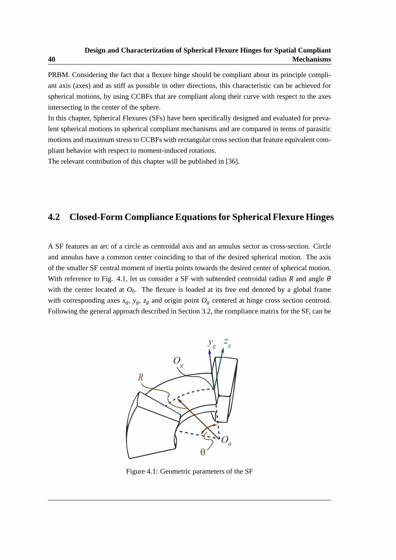
4.2 Closed-Form Compliance Equations for Spherical Flexure Hinges
A SF features an arc of a circle as centroidal axis and an annulus sectoras cross-section. Circle
and annulus have a common center coinciding to that of the desired spherical motion. The axis
of the smaller SF central moment of inertia points towards the desired center ofspherical motion.
With reference to Fig. 4.1, let us consider a SF with subtended centroidal radiusR and angleθwith the center located atO0. The flexure is loaded at its free end denoted by a global frame
with corresponding axesxg, yg, zg and origin pointOg centered at hinge cross section centroid.
Following the general approach described in Section 3.2, the compliance matrix for the SF, can be
zg
θ
Og
R
yg
O0
Figure 4.1: Geometric parameters of the SF

4.3 Defining Cross Section Properties for the Spherical Flexure 41
obtained as follows:
gC =
Cx, fx Cx, fy 0 0 0 Cx,mz
Cy, fx Cy, fy 0 0 0 Cy,mz
0 0 Cz, fz Cz,mx Cz,my 0
0 0 Cθx, fz Cθx,mx Cθx,my 0
0 0 Cθy, fz Cθy,mx Cθy,my 0
Cθz, fx Cθz, fy 0 0 0 Cθz,mz
(4.1)
Neglecting shear deformations, being a slender beam, the compliance factors for the matrixgC is
reported in Table 4.1. Each compliance factor is written in terms of the cross section area, area
and polar moments of inertia (namelyA, Im, In, andJ). In particular, these properties are derived
as a function of the SF geometric parameters in the following section.
4.3 Defining Cross Section Properties for the Spherical Flexure
In particular, the SF cross section is an annular sector (Fig. 4.2), that can be considered as the
common section of two concentric circular sectors with different radius. Let us considerri andro
as the radius of the inner and the outer circular sectors respectively. Assumingβ as the subtended
Table 4.1: Compliance factors for the SF loaded at the free end
Cx, fx =R(Acos(θ)sin(θ)R2−4Asin(θ)R2+3AR2θ+cos(θ)sin(θ)In+Inθ)
2EAIn
Cx, fy =Cy, fx =−R(A(cos(θ))2R2−2R2Acos(θ)+R2A+(cos(θ))2In−In)
2EAIn
Cx,mz =Cθz, fx =R2(sin(θ)−θ)
EIn
Cy, fy =−R(cos(θ)sin(θ)−θ)(R2A+In)
2EAIn
Cy,mz =Cθz, fy =−R2(cos(θ)−1)EIn
Cz, fz =R3(EIm cos(θ)sin(θ)−GJ cos(θ)sin(θ)−4EIm sin(θ)+3EImθ+GJθ)
2GJEIm
Cz,mx =Cθx, fz =R2(EIm cos(θ)sin(θ)−GJ cos(θ)sin(θ)−2EIm sin(θ)+EImθ+GJθ)
2GJEIm
Cz,my =Cθy, fz =−R2(EIm(cos(θ))2−GJ(cos(θ))2−2EIm cos(θ)+EIm+GJ)
2GJEIm
Cθx,mx =R(EIm cos(θ)sin(θ)−GJ cos(θ)sin(θ)+EImθ+GJθ)
2GJEIm
Cθx,my =Cθy,mx =R(EIm−GJ)(sin(θ))2
2GJEIm
Cθy,my =− R(EIm cos(θ)sin(θ)−GJ cos(θ)sin(θ)−EImθ−GJθ)2GJEIm
Cθz,mz =RθEIn

42Design and Characterization of Spherical Flexure Hinges for SpatialCompliant
Mechanisms
Centroid
roR
z
O0
β
ri
zl(n)
y,yl(m)
Figure 4.2: Cross section properties of the SF
angle of the annular sector, the cross section area can be obtained by using definite integration
over the annular sector as follows:
A =
β/2∫
−β/2
ro∫
ri
r dr dβ =r2
oβ2
−r2
i β2
=(r2
o − r2i )β
2(4.2)
In order to derive area and polar moments of inertia with respect to the centroidal axis, we need to
locate the centroid of the annular cross section. Using the definition for the first moment of area,
one can obtain:
Sy = Az =∫
AzdA =
β/2∫
−β/2
ro∫
ri
(r sinβ )r dr dβ = 0⇒ z = Sy/A = 0 (4.3)
Sz = Ay =∫
AydA =
β/2∫
−β/2
ro∫
ri
(r cosβ )r dr dβ =23(r3
o − r3i )sinβ/2
⇒ y = Sz/A =43(r3
o − r3i )sinβ/2
(r2o − r2
i )β= R
(4.4)
whereSy andSz are the first moments of area abouty andz axes. The area moments of inertia with
respect toy andz axes, can then be written as:
Iy =∫
Az2 dA =
β/2∫
−β/2
ro∫
ri
(r sinβ )2r dr dβ =18(r4
o − r4i )(β −sinβ ) (4.5)
4.4 Stress Considerations 43
Iz =∫
Ay2 dA =
β/2∫
−β/2
ro∫
ri
(r cosβ )2r dr dβ =18(r4
o − r4i )(β +sinβ ) (4.6)
By applying parallel axis theorem [37], one can find the area and polar moments of inertia with
respect to the centroidal axis, transfering them fromy andz to yl andzl axes:
Im = Iy =18(r4
o − r4i )(β −sinβ ) (4.7)
In = Iz −AR2 =18(r4
o − r4i )(β +sinβ )−
89(r3
o − r3i )
2sin2(β/2)
(r2o − r2
i )β(4.8)
J = Im + In =14(r4
o − r4i )β −
89(r3
o − r3i )
2sin2(β/2)
(r2o − r2
i )β(4.9)
Replacing Eqs. 4.2,4.7,4.8 and 4.9 in Table 4.1, the compliance matrix for the SF willbe deter-
mined as a function of the hinge geometric parameters and the applied material.
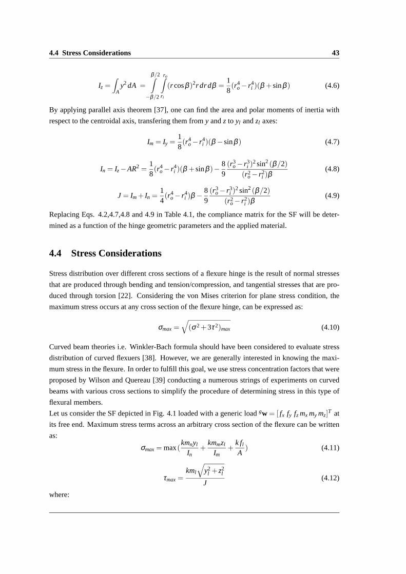
4.4 Stress Considerations
Stress distribution over different cross sections of a flexure hinge is theresult of normal stresses
that are produced through bending and tension/compression, and tangential stresses that are pro-
duced through torsion [22]. Considering the von Mises criterion for plane stress condition, the
maximum stress occurs at any cross section of the flexure hinge, can be expressed as:
σmax =√(σ2+3τ2)max (4.10)
Curved beam theories i.e. Winkler-Bach formula should have been considered to evaluate stress
distribution of curved flexuers [38]. However, we are generally interested in knowing the maxi-
mum stress in the flexure. In order to fulfill this goal, we use stress concentration factors that were
proposed by Wilson and Quereau [39] conducting a numerous strings ofexperiments on curved
beams with various cross sections to simplify the procedure of determining stress in this type of
flexural members.
Let us consider the SF depicted in Fig. 4.1 loaded with a generic loadgw = [ fx fy fz mx my mz]T at
its free end. Maximum stress terms across an arbitrary cross section of theflexure can be written
as:
σmax = max(kmnyl
In+
kmmzl
Im+
k fl
A) (4.11)
τmax =kml
√y2
l + z2l
J(4.12)
where:

44Design and Characterization of Spherical Flexure Hinges for SpatialCompliant
Mechanisms
fl = fx cos(θ)+ fy sin(θ)
ml =− fzR(1−cos(θ))+mx cos(θ)+my sin(θ)
mn =− fxR(1−cos(θ))+mz + fyRsin(θ)
mm =− fzR(sin(θ)−mx sin(θ)+my cos(θ)
yl andzl are the maximum longitudinal and transversal lengths measured from the cross section
centroid. Considering the cross section symmetry, these lengths could encompass positive or
negative quantities based on the loading profile.k is the empirical formula for stress correction
factors for curved flexures and can be obtained from [39]:
k = 1+0.5In
bc2
{1
R− c+
1R
}(4.13)
where:
b = maximum breadth of section
c = distance from centroidal axis to the inner fiber
In applications that the loading is not known or fully determined but the deformation of the flexure
free end is specified, the recent stress equations can be expressed inthe displacement domain using
the following transformation between compliance and stiffness matrices:
gw = gK .gs; gK = gC−1 (4.14)
wheregs is the deformation of the flexure free end in the global coordinate system.
4.5 Numerical Example and Model Validation
The SF depicted in Fig. 4.1 is considered as a case study. The geometric parameters employed in
the simulation arero = 60mm,ri = 50mm,θ = π/3 andα = π/180. The hinge is made of Acrylic
Plastic with Young’s modulusE = 3000MPa and Poisson’s ratioν = 0.33. The aforementioned
theoretical procedure is adopted to estimate the SF compliance matrix. Results are then validated
through FEA performed with the commercial software COMSOL (Fig. 4.3). Table 4.2 compares
the results obtained via numerical model and FEA. The comparison shows a close agreement
between the two methods.
In order to evaluate the flexure performance, we have compared the aforementioned SF with a
rectangular cross section CCBF having identical centroidal axes and subtended angles. In addition,
the two flexures are suitably dimensioned in order to present the same compliant behavior with
respect to moment-induced rotations. The resulting CCBF width and thicknessarew = 9.98mm
andt = 0.963mm. By applying the method described in Section 3.3, the CCBF compliance matrix

4.5 Numerical Example and Model Validation 45
Figure 4.3: FEA of the SF
has been computed and numerical data are shown in Table 4.3. As we can see, the compliance
factors become identical for the two flexures with the exception ofCx, fx , Cx, fy andCy, fx , which
represent undesired (secondary) compliances in all those application requiring a spherical motion.
Naturally, unavoidable secondary compliances should be minimized in order todecrease parasitic
motions as much as possible. A quantitative comparison between SF and CCBF can then be
achieved by defining two compliance ratios as follows:
rx,x =CSF
x, fx
CCCBFx, fx
; rx,y =CSF
x, fy
CCCBFx, fy
=CSF
y, fx
CCCBFy, fx
(4.15)
where each SF compliance factor (referred to with SF superscript) is divided by the corresponding
CCBF compliance factor (referred to with CCBF superscript). In order tounderstand the behavior
of SFs and CCBFs in terms of parasitic motions, we have assessed the influence of the geometric
parameters on these two factors. This goal is achieved by evaluating the compliance ratiosrx,x
Table 4.2: Compliance factors for the SF and comparison between analyticaland FEA results
Compliance factors Cx, fx Cx, fy =Cy, fx Cx,mz =Cθz, fx Cy, fy Cy,mz =Cθz, fy Cz, fz
Analytic 4.0146e-5 -8.6900e-5 -0.0023 2.1584e-4 0.0064 0.0232
FEA 4.0149e-5 -8.6947e-5 -0.0023 2.1594e-4 0.0064 0.0232
Percentage error 7.5e-3 0.054 0 0.046 0 0
Compliance factors Cθx,mx Cz,mx =Cθx, fz Cx,my =Cθy, fz Cθy,my Cθx,my =Cθy,mx Cθz,mz
Analytic 8.0448 0.4147 -0.5158 18.4932 -9.0486 0.2413
FEA 8.0466 0.4148 -0.5159 18.4966 -9.0492 0.2413
Percentage error 0.022 0.024 0.019 0.018 6.6e-3 0

46Design and Characterization of Spherical Flexure Hinges for SpatialCompliant
Mechanisms
Table 4.3: Compliance factors for the similar CCBF
Compliance elements Cx, fx Cx, fy =Cy, fx Cx,mz =Cθz, fx Cy, fy Cy,mz =Cθz, fy Cz, fz
Value 4.0144e-5 -8.6901e-5 -0.0023 2.1584e-4 0.0064 0.0232
Compliance elements Cθx,mx Cz,mx =Cθx, fz Cx,my =Cθy, fz Cθy,my Cθx,my =Cθy,mx Cθz,mz
Value 8.0448 0.4147 -0.5158 18.4932 -9.0486 0.2413
andrx,y for varying values ofR andθ . Fig. 4.4 and Fig. 4.5 respectively represent the values
(1− rx,x)×100 and(1− rx,y)×100 as function ofR andθ . From these two graphs,rx,y is always
negative whereasrx, fx is always positive, meaning that it is impossible to assess which flexure
presents the best selectively compliant behavior without considering a specific loading condition.
It is also worth mentioning that by increasing the length of the flexures, the ratios rx,x andrx,y are
tending to 1, which imply a similar deformation behavior for relatively large length-to-thickness
ratios. For what concerns the overall Von Mises stress on each flexure when loaded with a (prin-
cipal) bending momentmy on the free end, the following stress ratio has been defined:
rσ =σSF
max
σCCBFmax
(4.16)
We have obtained this ratio for varying values ofR andθ . In particular, the ratiorσ assumes a
constant value equaling 0.918 at varyingR whereas the influence ofθ is shown in Fig. 4.6. As we
can see, SF outperforms CCBF, being characterized by a lower stress level for equal load (meaning
that the SF outperforms CCBF in terms of maximum achievable rotation).
0.01 0.02 0.03 0.04 0.05
−0.05
0
0.05
Flexure radius (m)
(1−
com
pli
an
ce r
ati
o)%
(1−rxx
)%
(1−rxy
)%
Figure 4.4: Influence of varyingR on compliance ratios

4.5 Numerical Example and Model Validation 47
0.2 0.4 0.6 0.8 1 1.2
−0.1
−0.05
0
0.05
0.1
Flexure angle (rad)
(1−
com
pli
an
ce r
ati
o)%
(1−rxx
)%
(1−rxy
)%
Figure 4.5: Influence of varyingθ on compliance ratios
Flexure angle (rad)
Str
ess
rati
o
0.2 0.4 0.6 0.8 1 1.20.9
0.91
0.92
0.93
0.94
rs
Figure 4.6: Influence of varyingθ on stress ratio

48Design and Characterization of Spherical Flexure Hinges for SpatialCompliant
Mechanisms

Chapter 5
Compliance-Based Evaluation of a
Fully Compliant Spherical Chain with
Two Degrees of Freedom
This chapter introduces and investigates a fully compliant spherical chain that isobtained by the in-series connection of two identical primitive spherical flexureswith coincident center of spherical motion. The compliance matrix of the proposedchain is obtained via an analytical procedure and validated via finite element analy-sis. Comparison with an equivalent fully compliant chain employing straight beamflexures is also provided to highlight the added benefits when using primitivespher-ical flexures.
5.1 Introduction
Spherical mechanisms are an important class of spatial mechanisms that find vast applications in
pointing/orientation systems and mechanical transmissions [40]. These mechanisms are charac-
terized by having all points of their links moving on concentric spherical surfaces; the center of
these spheres being denoted as center of spherical motion. In its simplest form, a spherical chain
features the in-series connection of two or more revolute pairs with axes intersecting in the said
center of spherical motion.
Some studies have been proposed to investigate compliant mechanisms involvingspatial motions
as well as fully compliant spherical mechanisms.Smith [41] proposed compliantuniversal joints
fabricated from circular leaf springs, which also provided axial translation for self-alignment ap-
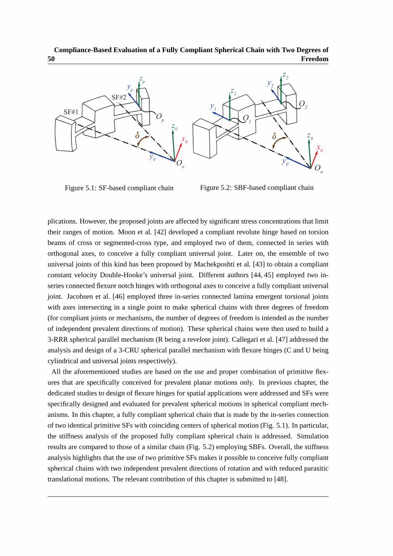
50Compliance-Based Evaluation of a Fully Compliant Spherical Chain with Two Degrees of
Freedom
x0
z0
d
y0
Oo
Op
yp
zp
SF#1
SF#2
Figure 5.1: SF-based compliant chain
x0
z0d
y0
Oo
O1
O2y
1
z1
z2
y2
Figure 5.2: SBF-based compliant chain
plications. However, the proposed joints are affected by significant stress concentrations that limit
their ranges of motion. Moon et al. [42] developed a compliant revolute hinge based on torsion
beams of cross or segmented-cross type, and employed two of them, connected in series with
orthogonal axes, to conceive a fully compliant universal joint. Later on, the ensemble of two
universal joints of this kind has been proposed by Machekposhti et al.[43] to obtain a compliant
constant velocity Double-Hooke’s universal joint. Different authors[44, 45] employed two in-
series connected flexure notch hinges with orthogonal axes to conceive a fully compliant universal
joint. Jacobsen et al. [46] employed three in-series connected lamina emergent torsional joints
with axes intersecting in a single point to make spherical chains with three degrees of freedom
(for compliant joints or mechanisms, the number of degrees of freedom is intended as the number
of independent prevalent directions of motion). These spherical chains were then used to build a
3-RRR spherical parallel mechanism (R being a revelote joint). Callegari et al. [47] addressed the
analysis and design of a 3-CRU spherical parallel mechanism with flexurehinges (C and U being
cylindrical and universal joints respectively).
All the aforementioned studies are based on the use and proper combinationof primitive flex-
ures that are specifically conceived for prevalent planar motions only.In previous chapter, the
dedicated studies to design of flexure hinges for spatial applications wereaddressed and SFs were
specifically designed and evaluated for prevalent spherical motions in spherical compliant mech-
anisms. In this chapter, a fully compliant spherical chain that is made by the in-series connection
of two identical primitive SFs with coinciding centers of spherical motion (Fig. 5.1). In particular,
the stiffness analysis of the proposed fully compliant spherical chain is addressed. Simulation
results are compared to those of a similar chain (Fig. 5.2) employing SBFs. Overall, the stiffness
analysis highlights that the use of two primitive SFs makes it possible to conceive fully compliant
spherical chains with two independent prevalent directions of rotation and with reduced parasitic
translational motions. The relevant contribution of this chapter is submitted to [48].

5.2 Closed-Form Compliance Equations for a Serial 2-SF Spherical Chain 51
5.2 Closed-Form Compliance Equations for a Serial 2-SF Spherical
Chain
Concerning the frame dependency, as explained in [17], compliance matrices at different reference
frames (e.g. from the frameSp to a generic frameS0 (Fig. 5.1)) can be related resorting to the 6x6
adjoint matix pT0:
pT0 =
[pR0 0
pr0 ·pR0
pR0
]=
0RTp 0
(0r p ·
0Rp)T 0RT
p
(5.1)
where pR0 denotes the rotation matrix of frameS0 with respect to frameSp (i.e. the columns
of pR0 are the unit vectors of frameS0 expressed in the coordinate frameSp), and0r p denotes
the skew symmetric matrix of the position vectorpr0, which locates the origin of frameS0 with
respect to frameSp.
Specifically, once the compliance matrixpC at frameSp is known, the compliance matrix related
to the frameS0 can be simply calculated as:
0C = 0T−Tp · pC · 0T−1
p = pTT0 · pC · pT0 (5.2)
whereT denotes the transpose of a matrix. As reported in [49], the 6x6 adjoint matrix is also
useful for characterizing a collection ofn in-series connected compliant flexures. In this case, the
overall system compliance can be simply obtained by summing up the compliance matrices of
each flexure, once all matrices are related to a common reference frameS0. Therefore, resorting
to Eq. 5.2, the following relation holds:
0C =n
∑g
0T−Tg · gC · 0T−1
g =n
∑g
gTT0 · gC · gT0 (5.3)
In the following, the procedure is outlined for the fully compliant spherical chain depicted in Fig.
5.1. The chain is composed by the in-series connection of two SFs (hereafter referred to as SF#1
and SF#2) that are both identical to the SF represented in Chapter 4 (Fig. 4.1) with centroidal axes
lying on the same circumference. The compliance matrix of each SF can then berecalled from
Section 4.2. Let us denote1C and2C as the compliance matrix of each SF as referred to the hinge
free end. The center of the spherical motion (i.e. pointO0 in Fig. 5.1) is then taken as the origin
of S0, the frame axes being oriented such thaty0 axis passes through the centroid of the SF#1 mid
cross section, whereasz0 axis is orthogonal to the symmetry plane containing the centroidal axes
(similar toz axis in Fig. 4.2).
As a further step, the adjoint matrices1T0 and2T0, respectively relating1C and2C to S0, should
be computed. Recalling Eq. 5.1, the rotation matrices,1R0 and2R0, and the translation vectors,1r0 and2r0, composing1T0 and2T0 are defined as follows:
1R0 =
cos(θ/2) −sin(θ/2) 0
sin(θ/2) cos(θ/2) 0
0 0 1
(5.4)

52Compliance-Based Evaluation of a Fully Compliant Spherical Chain with Two Degrees of
Freedom
Table 5.1: Compliance elements of the mechanism
Cx, fx =−R(−2(AR2+In)(cos2(δ )sin(θ)+θ))
2EAInCx, fy =Cy, fx =−
R(sin(2δ )sin(θ)(AR2+In))2EAIn
Cy, fy =R(2(AR2+In)(θ−cos2(δ )sin(θ)))
2EAInCx,mz =Cθz, fx =−
R2(−4cos2( δ2)sin( θ
2))EIn
Cy,mz =Cθz, fz =−R2(2sin(δ )sin( θ
2 ))EIn
Cz,mx =Cθx, fz =R2(−4cos2( δ
2)sin( θ2 ))
GJ
Cθx,mx =−R(−2GJ(θ−cos2(δ )sin(θ))−2EIm(cos2(δ )sin(θ)+θ))
2EGJImCz, fz = 2 R3θ
GJ
Cθx,my =Cθy,mx = Rsin(δ )cos(δ )sin(θ)(
1EIm
− 1GJ
)Cz,my =Cθy, fz =
R2(2sin(δ )sin( θ2))
GJ
Cθy,my =R(2GJ(cos2(δ )sin(θ)+θ)+2EIm(θ−cos2(δ )sin(θ)))
2EGJImCθz,mz = 2 Rθ
EIn
2R0 =
cos(θ/2+δ ) −sin(θ/2+δ ) 0
sin(θ/2+δ ) cos(θ/2+δ ) 0
0 0 1
(5.5)
1r0 =2r0 =
[0, −R, 0
]T(5.6)
whereR andθ represent the radius and subtended angle of SF#1 and SF#2 centroidal axes, whereas
δ is the angle between they0 axis and an axis connecting pointO0 and the centroid of the SF#2
mid cross section. The overall chain compliance matrix can then be computed resorting to Eq.
5.3, wheren = 2. In particular, the matrix0C can be expressed as follows:
0C =
Cx, fx Cx, fy 0 0 0 Cx,mz
Cy, fx Cy, fy 0 0 0 Cy,mz
0 0 Cz, fz Cz,mx Cz,my 0
0 0 Cθx, fz Cθx,mx Cθx,my 0
0 0 Cθy, fz Cθy,mx Cθy,my 0
Cθz, fx Cθz, fy 0 0 0 Cθz,mz
(5.7)
Matrix 0C relates the wrench0w acting onS0 to the corresponding generalized displacement0s,
(namely0s= 0C · 0w). The analytical expression of the matrix entries are reported in Table 5.1 as
a function of the geometric parameters and the employed material. The cross section properties
(A, Im, In, andJ) can be recalled from Section 4.3 as a function of the hinge geometric parameters.
5.3 Numerical Example and Model Validation
A fully-compliant spherical chain featuring two identical in-series SFs is considered as a case
study. The SF geometric parameters and the material employed for the simulationsare identical to

5.3 Numerical Example and Model Validation 53
Angle between flexures, δ [rad]
Co
mp
lia
nce
ele
men
ts
0.5 1 1.5 2 2.5 3
0
10
20
30
40
50
Cx,mx
Cy,my
Figure 5.3: Influence of varyingδ on principal compliances
the corresponding data used in Section 4.5. For a generic angleδ , the aforementioned theoretical
procedure is adopted to estimate the overall compliance matrix. The dependency of the principal
compliance elements,Cθx,mx andCθy,my , on the angleδ is shown in Fig. 5.3, which highlights that
Cθx,mx =Cθy,my whenδ = 90◦.
Results concerning this particular geometry (namelyδ = 90◦) are then validated through FEA per-
formed with the commercial software COMSOL. FEA simulations are executed byindividually
loading the chain along the axesx0, y0 andz0. The compliance elements are simply computed as
the ratios between each load component and the corresponding deformations. Table 5.2 compares
the results obtained via analytical model and FEA. The comparison shows a close agreement be-
Table 5.2: Compliance elements of the 2-SF spherical chain and comparison between analytical
and FEA results
Compliance elements Cx, fx Cx, fy =Cy, fx Cx,mz =Cθz, fx Cy, fy Cy,mz =Cθz, fy Cz, fz
Analytic 7.3603e-4 -5.9730e-20 0.0127 7.3603e-4 -0.0127 0.0039
FEA 7.3631e-4 -5.9000e-20 0.0127 7.3635e-4 -0.0127 0.0038
Percentage error 0.038 1.22 0 0.038 0 2.56
Compliance elements Cθx,mx Cz,mx =Cθx, fz Cz,my =Cθy, fz Cθy,my Cθx,my =Cθy,mx Cθz,mz
Analytic 26.5379 -0.0334 0.0334 26.5379 -4.9013e-15 0.4827
FEA 26.5455 -0.0334 0.0334 26.5455 -4.9000e-15 0.4842
Percentage error 0.028 0 0 0.028 0.026 0.31

54Compliance-Based Evaluation of a Fully Compliant Spherical Chain with Two Degrees of
Freedom
Table 5.3: Compliance elements of the 2-SBF spherical chain
Compliance elements Cx, fx Cx, fy =Cy, fx Cx,mz =Cθz, fx Cy, fy Cy,mz =Cθz, fy Cz, fz
Value 8.0311e-4 -4.0926e-20 0.0133 8.0311e-4 -0.0133 0.0183
Compliance elements Cθx,mx Cz,mx =Cθx, fz Cx,my =Cθy, fz Cθy,my Cθx,my =Cθy,mx Cθz,mz
Value 26.5379 -0.0350 0.0350 26.5379 -1.5472e-15 0.4827
tween the two methods.
As a further step, an SF-based chain has been compared with a similar chainfeaturing SBF flexures
and equal values of the principal compliance elements. Definingw and l as the SBF width and
length, the latter design constraint is achieved whenever both SBFs and SFs are characterized
by equal width (i.e.w = ro − ri), and same centroidal axes length (i.e.l = Rθ ). By applying
the method described in Section 5.2, the compliance matrix of the SBF-based chain has been
computed and numerical data are shown in Table 5.3. The pictures of the two considered design
solutions are reported in Figs. 5.4 and 5.5 which also show the chain deformed shapes (contour
plot of the total displacement) when a generic torque lying inx0− y0 plane is applied to the end-
link.
The quantitative comparison between the two design solutions is then performed by defining three
compliance ratios as follows:
r1 =|CSF
x, fx|
|CSBFx, fx
|; r2 =
|CSFx,mz
|
|CSBFx,mz
|=
|CSFθz, fx
|
|CSBFθz, fx
|=
|CSFz,mx
|
|CSBFz,mx
|=
|CSFθx, fz
|
|CSBFθx, fz
|; r3 =
|CSFz, fz
|
|CSBFz, fz
|; (5.8)
where each compliance element concerning the SF-based chain (referred to with SF superscript)
is divided by the corresponding compliance element concerning the SBF-based chain (referred to
with SBF superscript). In particular, the variablesr1, r2, andr3 represent ratios between unde-
sired (secondary) compliances in all those applications requiring a spherical motion. Therefore,
compliance ratios whose value is less than unity simply indicates that the SF-based chain out-
O0
Figure 5.4: Finite element model of the 2-SF
chain.
O0
Figure 5.5: Finite element model of the 2-SBF
chain.

5.3 Numerical Example and Model Validation 55
Flexure angle, θ [rad]
Com
pli
ance
rati
o
0.5 1 1.5
0.2
0.4
0.6
0.8
1
r2
r3
r1
Figure 5.6: Influence of varyingθ on compliance ratios
performs the SBF-based chain in terms of parasitic motions. As an example, for a given radius
R= 55.2mm, the values ofr1, r2 andr3 as a function ofθ are reported in Fig. 5.6. For a given angle
θ = π/3, the compliance ratios are constant (independent ofR), namelyr1 = 0.9191,r2 = 0.9549
andr3 = 0.2115. In conclusion, for what concerns this particular case study, numerical simulations
confirm the benefits when using the primitive SF as compared to the traditional SBF.

56Compliance-Based Evaluation of a Fully Compliant Spherical Chain with Two Degrees of
Freedom
Chapter 6
Design and Analysis of a Fully
Compliant Passive Spherical Joint
Using Spherical Flexure Hinges
In this chapter, a new type of passive compliant spherical joint is represented. Thejoint is made by the in-parallel connection of two fully compliant spherical chains.Each chain is composed of three identical spherical flexures connectedin-serieswith mutually orthogonal axes. The closed-form compliance equations for thespherical joint are derived via the previously described analytical method. Thecompliant spherical chain is also evaluated comparing with the equivalent compli-ant chain employing straight beam flexures.
6.1 Introduction
In previous chapter, relevant studies dedicated to compliant mechanisms involving spherical mo-
tions as well as compliant spherical mechanisms were reviewed and a fully compliant spherical
chain with two degrees of freedom was introduced and evaluated. In this chapter, a compliant
passive spherical joint is represented. Few studies have been dedicated to analysing and design-
ing compliant passive spherical joints. Lobontiu and Paine [33] providedanalytical solution for
designing circular cross-section corner-filleted flexures (Fig. 6.1(a)) for three-dimensional com-
pliant mechanisms. These flexures have been used as a compliant substitutefor spherical pairs
in the literature. However, they suffer from anisotropic deforming behavior unlike identical ball
joints, and difficult machining and manufacturing process. Daihong et al. [50] have proposed a

58Design and Analysis of a Fully Compliant Passive Spherical Joint Using Spherical Flexure
Hinges
(a) Circular cross-section corner-filleted flexures (b) Spherical joint proposed by Daihong et al. [50]
(c) Spherical joint proposed by Hesselbach et al. [44] (d) Spherical joint presented in this study
Figure 6.1: Compliant spherical joints
cubic compliant spherical joint (Fig. 6.1(b)) to use in their 6-DOF compliant manipulator. They
have used three circular flexures as revolute pairs with intersecting compliant axes. Hesselbach
et al. [44] have applied three set of elliptical flexures in their composed compliant spherical joint
(Fig. 6.1(c)). The spherical joint introduced in this chapter, is proposed using six identical SFs
composing the in-parallel connection of two 3-SF compliant spherical chains (Fig. 6.1(d)). This
joint demonstrates a fully isotropic and decoupled deformation behavior to applied loads.
6.2 Closed-Form Compliance Equations for the Spherical Joint
The compliant spherical pair proposed in this chapter is composed of two 3-SF compliant spherical
chains and can provide 3 rotational degrees of freedom between the input shaft (fixed) and the
output shaft as depicted in Fig. 6.2(a). Let us denote as Chain#1 (Fig. 6.2(b)) and Chain#2 (Fig.

6.2 Closed-Form Compliance Equations for the Spherical Joint 59
x0
z0
y0
Input ShaftOutput Shaft
O0
(a) Compliant spherical joint studied in this chapter
y0
x0
z0
x2
x3
z1
z2
z3
y1
y2
y3
x1
q/2
q/2
q/2
O0
O3
O1
O2
SF#2
SF#3
SF#1
(b) Chain#1
y0
x0
z0
z4y
4
x4
z5
y5
x5
z6
y6
x6
q/2
q/2
q/2
O0
O4
O5
O6
SF#4
SF#5
SF#6
(c) Chain#2
Figure 6.2: Compliant spherical joint composed of two spherical chains
6.2(c)), the upper and lower spherical chains respectively. Each chain is made by the in-series
connection of three SFs (namely SF#1,2,3 for Chain#1 and SF#4,5,6 for Chain#2) as shown in
Fig. 6.2. All of the SFs are identical to the SF represented in Chapter 4 (Fig.4.1). The flexures
in each chain are located such that their centriodal axes are lying in three mutually orthogonal
planes. This imposes the joint to have an isotropic configuration. The frameS0 is adopted at the
center of the spherical motion (O0) such thaty0, x0 andz0 axes pass through the geometric center
of SF#1,4, SF#2,5 and SF#3,6 respectively. Resorting to Eq. 5.3, the overall compliance matrix
for Chain#1 and Chain#2 can be obtained as follows:
0CChain#1=3
∑g=1
0T−Tg · gC · 0T−1
g =3
∑g=1
gTT0 · gC · gT0 (6.1)
0CChain#2=6
∑g=4
0T−Tg · gC · 0T−1
g =6
∑g=4
gTT0 · iC · gT0 (6.2)
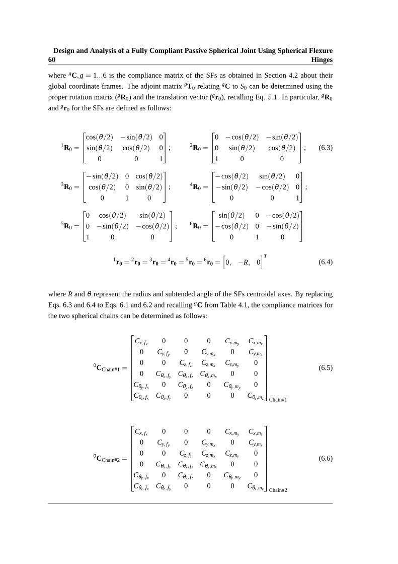
60Design and Analysis of a Fully Compliant Passive Spherical Joint Using Spherical Flexure
Hinges
wheregC,g = 1...6 is the compliance matrix of the SFs as obtained in Section 4.2 about their
global coordinate frames. The adjoint matrixgT0 relatinggC to S0 can be determined using the
proper rotation matrix (gR0) and the translation vector (gr0), recalling Eq. 5.1. In particular,gR0
andgr0 for the SFs are defined as follows:
1R0 =
cos(θ/2) −sin(θ/2) 0
sin(θ/2) cos(θ/2) 0
0 0 1
; 2R0 =
0 −cos(θ/2) −sin(θ/2)
0 sin(θ/2) cos(θ/2)
1 0 0
; (6.3)
3R0 =
−sin(θ/2) 0 cos(θ/2)
cos(θ/2) 0 sin(θ/2)
0 1 0
; 4R0 =
−cos(θ/2) sin(θ/2) 0
−sin(θ/2) −cos(θ/2) 0
0 0 1
;
5R0 =
0 cos(θ/2) sin(θ/2)
0 −sin(θ/2) −cos(θ/2)
1 0 0
; 6R0 =
sin(θ/2) 0 −cos(θ/2)
−cos(θ/2) 0 −sin(θ/2)
0 1 0
1r0 =2r0 =
3r0 =4r0 =
5r0 =6r0 =
[0, −R, 0
]T(6.4)
whereR andθ represent the radius and subtended angle of the SFs centroidal axes.By replacing
Eqs. 6.3 and 6.4 to Eqs. 6.1 and 6.2 and recallinggC from Table 4.1, the compliance matrices for
the two spherical chains can be determined as follows:
0CChain#1=
Cx, fx 0 0 0 Cx,my Cx,mz
0 Cy, fy 0 Cy,mx 0 Cy,mz
0 0 Cz, fz Cz,mx Cz,my 0
0 Cθx, fy Cθx, fz Cθx,mx 0 0
Cθy, fx 0 Cθy, fz 0 Cθy,my 0
Cθz, fx Cθz, fy 0 0 0 Cθz,mz
Chain#1
(6.5)
0CChain#2=
Cx, fx 0 0 0 Cx,my Cx,mz
0 Cy, fy 0 Cy,mx 0 Cy,mz
0 0 Cz, fz Cz,mx Cz,my 0
0 Cθx, fy Cθx, fz Cθx,mx 0 0
Cθy, fx 0 Cθy, fz 0 Cθy,my 0
Cθz, fx Cθz, fy 0 0 0 Cθz,mz
Chain#2
(6.6)

6.3 Numerical Example and Model Validation 61
Table 6.1: Compliance factors for the two spherical chains
{Cx, fx =Cy, fy =Cz, fz}Chain#1= {Cx, fx =Cy, fy =Cz, fz}Chain#2=Rθ (InGJ+GJR2A+R2EAIn)
EAInGJ
{Cx,my =Cy,mz =Cz,mx =Cθx, fz =Cθy, fx =Cθz, fy}Chain#1=
−{Cx,my =Cy,mz =Cz,mx =Cθx, fz =Cθy, fx =Cθz, fy}Chain#2=−2 R2 sin(θ/2)GJ
{Cθx,mx =Cθy,my =Cθz,mz}Chain#1= {Cθx,mx =Cθy,my =Cθz,mz}Chain#2=Rθ (InEIm+InGJ+GJIm)
GJEImIn
{Cx,mz =Cy,mx =Cz,my =Cθx, fy =Cθy, fz =Cθz, fx}Chain#1=
−{Cx,mz =Cy,mx =Cz,my =Cθx, fy =Cθy, fz =Cθz, fx}Chain#2= 2 R2 sin(θ/2)EIn
The analytical expressions for the matrix entries are reported in Table 6.1.The cross section
properties (A, Im, In, andJ) can be recalled from Section 4.3 as a function of the hinge geometric
parameters.
A similar procedure can be adopted to obtain the overall compliance matrix of thespherical joint,
considering the fact that for parallel combinations, stiffness matrices of the chains should be
summed up in the same reference frame:
0K =2
∑i=1
0Ti ·iK · 0TT
i = 0CChain#1−1
+ 0CChain#2−1
(6.7)
The compliance matrix of the joint(0C), will be then obtained by inverting it’s stiffness matrix:
0C = 0K−1
(6.8)
Matrix 0C relates the wrench0w acting onS0 to the corresponding generalized displacement0sas
follows:
0s= 0C · 0w (6.9)
0s=[u0 v0 w0 α0 φ0 ψ0
]T
0w =[
fx0 fy0 fz0 mx0 my0 mz0
]T
6.3 Numerical Example and Model Validation
The spherical joint depicted in Fig. 6.2 is considered for the case study. The joint is composed of
two serial chains with six identical SFs. The SF geometric parameters and the material employed
for the simulations are identical to the corresponding data used in Section 4.5.The analytical
method described earlier and FEA are both used to evaluate the compliance matrices of Chain#1
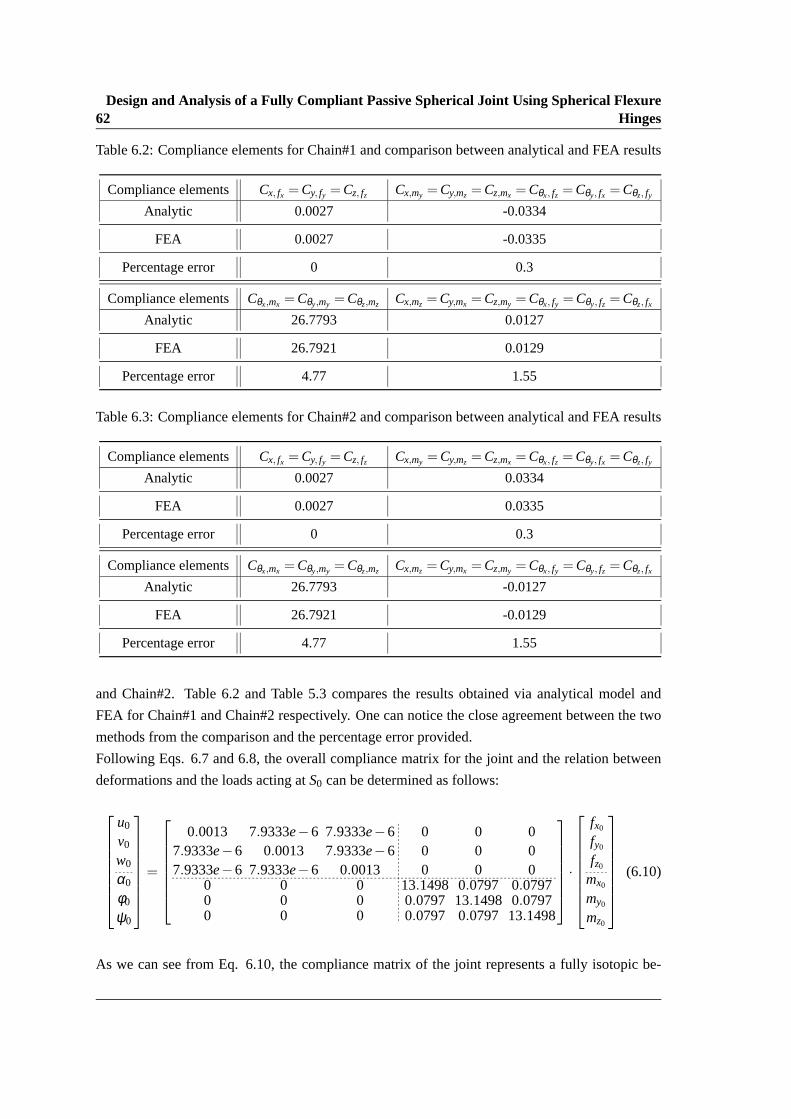
62Design and Analysis of a Fully Compliant Passive Spherical Joint Using Spherical Flexure
Hinges
Table 6.2: Compliance elements for Chain#1 and comparison between analytical and FEA results
Compliance elements Cx, fx =Cy, fy =Cz, fz Cx,my =Cy,mz =Cz,mx =Cθx, fz =Cθy, fx =Cθz, fy
Analytic 0.0027 -0.0334
FEA 0.0027 -0.0335
Percentage error 0 0.3
Compliance elements Cθx,mx =Cθy,my =Cθz,mz Cx,mz =Cy,mx =Cz,my =Cθx, fy =Cθy, fz =Cθz, fx
Analytic 26.7793 0.0127
FEA 26.7921 0.0129
Percentage error 4.77 1.55
Table 6.3: Compliance elements for Chain#2 and comparison between analytical and FEA results
Compliance elements Cx, fx =Cy, fy =Cz, fz Cx,my =Cy,mz =Cz,mx =Cθx, fz =Cθy, fx =Cθz, fy
Analytic 0.0027 0.0334
FEA 0.0027 0.0335
Percentage error 0 0.3
Compliance elements Cθx,mx =Cθy,my =Cθz,mz Cx,mz =Cy,mx =Cz,my =Cθx, fy =Cθy, fz =Cθz, fx
Analytic 26.7793 -0.0127
FEA 26.7921 -0.0129
Percentage error 4.77 1.55
and Chain#2. Table 6.2 and Table 5.3 compares the results obtained via analytical model and
FEA for Chain#1 and Chain#2 respectively. One can notice the close agreement between the two
methods from the comparison and the percentage error provided.
Following Eqs. 6.7 and 6.8, the overall compliance matrix for the joint and the relation between
deformations and the loads acting atS0 can be determined as follows:
u0
v0
w0
α0
φ0
ψ0
=
0.0013 7.9333e−6 7.9333e−6 0 0 07.9333e−6 0.0013 7.9333e−6 0 0 07.9333e−6 7.9333e−6 0.0013 0 0 0
0 0 0 13.1498 0.0797 0.07970 0 0 0.0797 13.1498 0.07970 0 0 0.0797 0.0797 13.1498
·
fx0
fy0
fz0
mx0
my0
mz0
(6.10)
As we can see from Eq. 6.10, the compliance matrix of the joint represents a fully isotopic be-
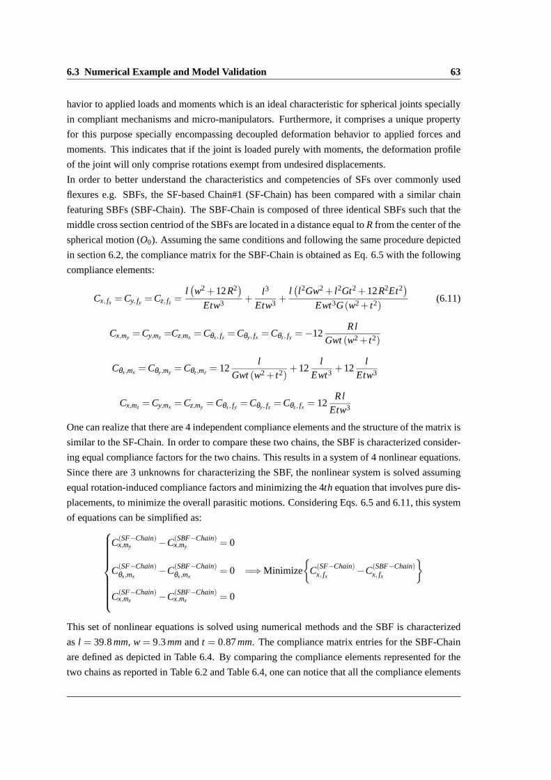
6.3 Numerical Example and Model Validation 63
havior to applied loads and moments which is an ideal characteristic for spherical joints specially
in compliant mechanisms and micro-manipulators. Furthermore, it comprises a unique property
for this purpose specially encompassing decoupled deformation behaviorto applied forces and
moments. This indicates that if the joint is loaded purely with moments, the deformationprofile
of the joint will only comprise rotations exempt from undesired displacements.
In order to better understand the characteristics and competencies of SFsover commonly used
flexures e.g. SBFs, the SF-based Chain#1 (SF-Chain) has been compared with a similar chain
featuring SBFs (SBF-Chain). The SBF-Chain is composed of three identical SBFs such that the
middle cross section centriod of the SBFs are located in a distance equal toR from the center of the
spherical motion (O0). Assuming the same conditions and following the same procedure depicted
in section 6.2, the compliance matrix for the SBF-Chain is obtained as Eq. 6.5 with the following
compliance elements:
Cx, fx =Cy, fy =Cz, fz =l(w2+12R2
)
Etw3 +l3
Etw3 +l(l2Gw2+ l2Gt2+12R2Et2
)
Ewt3G(w2+ t2)(6.11)
Cx,my =Cy,mz =Cz,mx =Cθx, fz =Cθy, fx =Cθz, fy =−12Rl
Gwt (w2+ t2)
Cθx,mx =Cθy,my =Cθz,mz = 12l
Gwt (w2+ t2)+12
lEwt3 +12
lEtw3
Cx,mz =Cy,mx =Cz,my =Cθx, fy =Cθy, fz =Cθz, fx = 12Rl
Etw3
One can realize that there are 4 independent compliance elements and the structure of the matrix is
similar to the SF-Chain. In order to compare these two chains, the SBF is characterized consider-
ing equal compliance factors for the two chains. This results in a system of 4nonlinear equations.
Since there are 3 unknowns for characterizing the SBF, the nonlinear system is solved assuming
equal rotation-induced compliance factors and minimizing the 4th equation that involves pure dis-
placements, to minimize the overall parasitic motions. Considering Eqs. 6.5 and 6.11, this system
of equations can be simplified as:
C(SF−Chain)x,my −C(SBF−Chain)
x,my = 0
C(SF−Chain)θx,mx
−C(SBF−Chain)θx,mx
= 0 =⇒ Minimize
{C(SF−Chain)
x, fx−C(SBF−Chain)
x, fx
}
C(SF−Chain)x,mz −C(SBF−Chain)
x,mz = 0
This set of nonlinear equations is solved using numerical methods and the SBF is characterized
asl = 39.8mm, w = 9.3mm andt = 0.87mm. The compliance matrix entries for the SBF-Chain
are defined as depicted in Table 6.4. By comparing the compliance elements represented for the
two chains as reported in Table 6.2 and Table 6.4, one can notice that all the compliance elements

64Design and Analysis of a Fully Compliant Passive Spherical Joint Using Spherical Flexure
Hinges
Table 6.4: Compliance elements for the SBF-Chain
Compliance elements Cx, fx =Cy, fy =Cz, fz Cx,my =Cy,mz =Cz,mx =Cθx, fz =Cθy, fx =Cθz, fy
Value 0.0060 -0.0334
Compliance elements Cθx,mx =Cθy,my =Cθz,mz Cx,mz =Cy,mx =Cz,my =Cθx, fy =Cθy, fz =Cθz, fx
Value 26.7793 0.0127
for the both chains are equal except the three for translational terms which are also representative
of parasitic motions. This term is equal to 0.0027 for the SF-Chain and 0.006 for the SBF-Chain.
This clarifies the outperforming behavior of SFs in comparison with SBFs in terms of parasitic
motions. The numerical values of the compliance matrix entries for the SF-Chainand SBF-Chain
are depicted in Fig. 6.3 and Fig. 6.4 respectively. As described in Section 3.4, this 3D bar graph
representation allows a qualitative comparison of the spherical chains in terms of compliance fac-
tors.
As a further step, the SF and SBF have been compared in terms of maximum stress levels. Consid-
ering the von Mises criterion as explained in Section 4.4, the two flexures have been evaluated by
the maximum von Mises stress when loaded with a unit (principal) bending momentmy on the free
end. In particular, the SBF assumes a constant value equaling 8.48e8Pa along its length where
the stress distribution for the SF along its centroidal axis, is depicted in Fig. 6.5. The maximum
stress for the SF occurs at its free end and is equal to 6.25e8Pa. As we can see, the SF furthermore
outperforms SBF in terms of maximum achievable rotation, being characterizedby a lower stress
level for equal load.
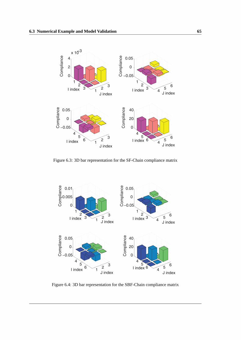
6.3 Numerical Example and Model Validation 65
12
31
23
0
2
4
x 10−3
J indexI index
Co
mp
lian
ce
45
61
23
−0.05
0
0.05
J indexI index
Co
mp
lian
ce
12
34
56
−0.05
0
0.05
J indexI index
Co
mp
lian
ce
45
64
56
0
20
40
J indexI index
Co
mp
lian
ce
Figure 6.3: 3D bar representation for the SF-Chain compliance matrix
12
31
23
0
0.005
0.01
J indexI index
Co
mp
lian
ce
45
61
23
−0.05
0
0.05
J indexI index
Co
mp
lian
ce
12
34
56
−0.05
0
0.05
J indexI index
Co
mp
lian
ce
45
64
56
0
20
40
J index
I index
Co
mp
lian
ce
Figure 6.4: 3D bar representation for the SBF-Chain compliance matrix

66Design and Analysis of a Fully Compliant Passive Spherical Joint Using Spherical Flexure
Hinges
0 0.2 0.4 0.6 0.8 13
3.5
4
4.5
5
5.5
6
6.5x 10
8
Flexure angle (rad)
Ma
xim
um
str
ess (
Pa
)
Figure 6.5: Maximum von Mises stress for the SF along its axis

Chapter 7
Conclusion
Flexure-based compliant mechanisms have become increasingly popular in different research ar-
eas, considering their advantages compared to traditional rigid-body mechanisms. These compli-
ant mechanisms gain some or all of their mobility due to the elastic deformation of theirflexible
members known as flexure hinges. Flexure hinges are characterized bylight weight, no need for
lubrication, no backlash, no friction losses and an easy manufacturing process. In this thesis, new
types of flexure hinges with curved centroidal axes were introduced and studied for both planar
and spatial applications. First, circularly curved-beam flexures were characterized and particularly
designed for planar applications, such as articulated robotic fingers. The closed-form compliance
equations for this type of flexures were fully derived as a function of their geometric parameters
and the employed material. These flexures were further compared to commonlyused straight
beam flexures considering the potential applications in the optimal design of compliant robotic
fingers. It was shown that circularly curved-beam flexures are better alternatives for achieving
maximum rotation demands in planar applications. Spherical flexure hinges were then introduced
and specifically designed for spatial applications involving spherical motions such as compliant
spherical mechanisms. These mechanisms are characterized by having allpoints of their links
moving on concentric spherical surfaces, the center of these spheresbeing denoted as center of
spherical motion. Spherical flexures were also characterized and theirclosed-form compliance
equations were derived. Proposing a feasible framework for comparing these flexures with cir-
cularly curved-beam flexures, for what concerns their capability in providing spherical motions,
proved that spherical flexures should be preferred over circularlycurved-beam flexures when opti-
mizing compliant spherical mechanisms. Spherical flexures were then usedin compliant spherical
chains and further evaluated comparing them with equivalent chains employing straight beam flex-
ures. The comparison further highlighted the superior characteristics ofspherical flexures. Finally
a new passive compliant spherical joint was designed using spherical flexures. The overall com-
pliance matrix of the joint demonstrated an exclusive deforming behavior with respect to applied
loads.

68 Conclusion

Bibliography
[1] E. McEwen, R. L. Miller, C. A. Bergman, Early bow design and construction, Scientific
American 264 (6) (1991) 76–82.
[2] W. Gurstelle, The Art of the Catapult: Build Greek Ballistae, Roman Onagers, English Tre-
buchets, and More Ancient Artillery, Chicago Review Press, 2004.
[3] Greek palintone, torsion-powered siege catapult,http://antique.mrugala.net/
Rome/Balliste%20romaine/Legion%20XXIV%20-%20roman%20ballista%
20siege%20catapult.htm, accessed: 2014-02-05.
[4] L. L. Howell, Compliant mechanisms, Wiley, New York, 2001.
[5] Y. Hirata, Liga process–micromachining technique using synchrotronradiation lithography–
and some industrial applications, Nuclear Instruments and Methods in Physics Research Sec-
tion B: Beam Interactions with Materials and Atoms 208 (2003) 21–26.
[6] F. Lotti, G. Vassura, A novel approach to mechanical design of articulated fingers for robotic
hands, in: IEEE/RSJ International Conference on Intelligent Robots and Systems, Vol. 2,
IEEE, 2002, pp. 1687–1692.
[7] N. Lobontiu, Compliant Mechanisms: Design of Flexure Hinges, CRC Press, 2002.
[8] A. Midha, I. Her, B. Salamon, Methodology for compliant mechanisms design: Part i- intro-
duction and large-deflection analysis., in: 18 th Annual ASME Design Automation Confer-
ence, 1992, pp. 29–38.
[9] L. L. Howell, A. Midha, A method for the design of compliant mechanisms withsmall-length
flexural pivots, Journal of Mechanical Design 116 (1) (1994) 280–290.
[10] L. Howell, A. Midha, Parametric deflection approximations for end-loaded, large-deflection
beams in compliant mechanisms, Journal of Mechanical Design 117 (1) (1995) 156–165.
[11] J. R. Cannon, L. L. Howell, A compliant contact-aided revolute joint, Mechanism and ma-
chine theory 40 (11) (2005) 1273–1293.

70 BIBLIOGRAPHY
[12] C. C. Tutum, et al., A compliant bistable mechanism design incorporating elastica buckling
beam theory and pseudo-rigid-body model, Journal of Mechanical Design 130 (4) (2008)
042304.
[13] B. D. Jensen, L. L. Howell, D. B. Gunyan, L. G. Salmon, The design and analysis of com-
pliant mems using the pseudo-rigid-body model, ASME-PUBLICATIONS-HTD 354 (1997)
119–126.
[14] S. Kota, Design of compliant mechanisms: applications to mems, in: 1999 Symposium on
Smart Structures and Materials, International Society for Optics and Photonics, 1999, pp.
45–54.
[15] C. P. Lusk, L. L. Howell, Components, building blocks, and demonstrations of spheri-
cal mechanisms in microelectromechanical systems, Journal of MechanicalDesign 130 (3)
(2008) 034503.
[16] L. L. Howell, C. M. DiBiasio, M. A. Cullinan, R. M. Panas, M. L. Culpepper, A pseudo-rigid-
body model for large deflections of fixed-clamped carbon nanotubes, Journal of Mechanisms
and Robotics 2 (3) (2010) 034501.
[17] S. Zhang, E. D. Fasse, A finite-element-based method to determine the spatial stiffness prop-
erties of a notch hinge, ASME Journal of Mechanical Design 123 (1) (2001) 141–147.
[18] S. Timoshenko, J. Goodier, Theory of Elasticity, no. 3, McGraw HillHigher Education,
1970.
[19] J. Paros, How to design flexure hinges, Mach Des 37 (1965) 151–156.
[20] B. Zettl, W. Szyszkowski, W. Zhang, On systematic errors of two-dimensional finite element
modeling of right circular planar flexure hinges, Journal of mechanicaldesign 127 (4) (2005)
782.
[21] W. Xu, T. King, Mechanical amplifier design for piezo-actuator applications, in: Innovative
Actuators for Mechatronic Systems, IEE Colloquium on, IET, 1995, p. 1.
[22] N. Lobontiu, J. Paine, E. Garcia, M. Goldfarb, Corner-filleted flexure hinges, Journal of
mechanical design 123 (3) (2001) 346–352.
[23] W. Schotborgh, F. Kokkeler, H. Tragter, F. van Houten, Dimensionless design graphs for
flexure elements and a comparison between three flexure elements, Precision engineering
29 (1) (2005) 41–47.
[24] Y. Tian, B. Shirinzadeh, D. Zhang, Y. Zhong, Three flexure hinges for compliant mechanism
designs based on dimensionless graph analysis, Precision Engineering 34 (1) (2010) 92–100.
BIBLIOGRAPHY 71
[25] G. Chen, X. Liu, Y. Du, Elliptical-arc-fillet flexure hinges: Towarda generalized model for
commonly used flexure hinges, Journal of mechanical design 133 (8) (2011) 81002.
[26] F. Lotti, G. Vassura, A novel approach to mechanical design of articulated fingers for robotic
hands, in: IEEE/RSJ IROS International Conference on Intelligent Robots and Systems,
2002.
[27] G. Berselli, G. Vassura, M. Piccinini, Comparative evaluation of the selective compliance in
elastic joints for robotic structures, IEEE ICRA, International Conference on Robotics and
Automation (2011) 759–764.
[28] A. Dollar, R. Howe, A robust compliant grasper via shape deposition manufacturing,
IEEE/ASME Transactions On Mechatronics 11 (2) (2006) 154–161.
[29] F. Parvari Rad, G. Berselli, R. Vertechy, V. Parenti-Castelli, Evaluating the spatial compliance
of circularly curved-beam flexures, Springer, Computational Kinematics, Mechanisms and
Machine Science Volume 15 (2014) 377–386.
[30] G. Berselli, F. Parvari Rad, R. Vertechy, V. Parenti-Castelli, Comparative evaluation of
straight and curved beam flexures for selectively compliant mechanisms,in: IEEE/ASME In-
ternational Conference on Advanced Intelligent Mechatronics (AIM),2013, pp. 1761–1766.
[31] M. Jafari, M. Mahjoob, An exact three-dimensional beam element with nonuniform cross
section, ASME Journal of Applied Mechanics 77 (6).
[32] N. Lobontiu, E. Garcia, Two-axis flexure hinges with axially-collocated and symmetric
notches, Computers & Structures 81 (13) (2003) 1329–1341.
[33] N. Lobontiu, J. Paine, Design of circular cross-section corner-filleted flexure hinges for three-
dimensional compliant mechanisms, Journal of mechanical design 124 (3) (2002) 479–484.
[34] S. Jagirdar, Kinematics of curved flexible beam, Ph.D. thesis, University of South Florida
(2006).
[35] G. Li, G. Chen, Achieving compliant spherical linkage designs fromcompliant planar link-
ages based on prbm: A spherical young mechanism case study, in: Robotics and Biomimetics
(ROBIO), 2012 IEEE International Conference on, IEEE, 2012, pp. 193–197.
[36] F. Parvari Rad, G. Berselli, R. Vertechy, V. Parenti-Castelli, Compliance based characteri-
zation of spherical flexure hinges for spatial compliant mechanisms, Springer, 19th CISM-
IFToMM Symposium on Robot Design, Dynamics, and Control (In Press)(2014) 1–8.
[37] P. Burton, Kinematics and Dynamics of Planar Machinery, Prentice Hall, 1979.

72 BIBLIOGRAPHY
[38] R. Huston, H. Josephs, Practical stress analysis in engineering design third edition, CRC
Press, 2009.
[39] B. J. Wilson, J. F. Quereau, A simple method of determining stress in curved flexural mem-
bers, University of Illinois, 1928.
[40] C. Chiang, Kinematics of Spherical Mechanisms, Krieger Publishing Company, 2000.
[41] S. Smith, Flexures, Elements of Elastic Mechanisms, Gordon and Breach Science Pub., 2000.
[42] B. Trease, Y. Moon, S. Kota, Design of large-displacement compliant joints, Journal of Me-
chanical Design 127 (4) (2005) 788–798.
[43] D. Farhadi Machekposhti, N. Tolou, J. L. Herder, The scope for a compliant homokinetic
coupling based on review of compliant joints and rigid-body constant velocity universal
joints, ASME IDETC, International Design Engineering Technical Conferences 4 (2012)
379–392.
[44] J. Hesselbach, J. Wrege, A. Raatz, O. Becker, Aspects on design of high precision parallel
robots, Assembly Automation 24 (1) (2004) 49–57.
[45] G. Palmieri, M. C. Palpacelli, M. Callegari, Study of a fully compliant u-joint designed for
minirobotics applications, ASME Journal of Mechanical Design 134 (11) (2012) 111003(9).
[46] J. O. Jacobsen, G. Chen, L. L. Howell, S. P. Magleby, Lamina emergent torsional (LET)
joint, Mechanims and Machine Theory 44 (11) (2009) 2098–2109.
[47] M. Callegari, A. Cammarata, A. Gabrielli, M. Ruggiu, R. Sinatra, Analysis and design of
a spherical micromechanism with flexure hinges, Journal of MechanicalDesign 131 (2009)
051003.
[48] F. Parvari Rad, G. Berselli, R. Vertechy, V. Parenti-Castelli, Stiffness analysis of a fully
compliant spherical chain with two degrees of freedom, Springer, Submittedto ARK, 14th
International Symposium on Advances in Robot Kinematics (2014) 1–8.
[49] L. Carter Hale, Principles and techniques for designing precision machines, Ph.D. thesis,
Dept. of Mech. Eng., MIT, Cambridge, MA (1999).
[50] C. Daihong, Z. Guanghua, L. Rong, Design of a 6-dof compliant manipulator based on
serial-parallel architecture, in: IEEE/ASME International Conferenceon Advanced Intel-
ligent Mechatronics, 2005, pp. 765–770.

Acknowledgements
I would like to sincerely thank my supervisor Prof. Vincenzo Parenti Castelli for all of his support
during my time as his student for his unparalleled patience, guidance, and generosity. He always
helped me maintain my perseverance when I needed to lighten up, and beyondthe realm of my
research, our numerous conversations together kept me motivated and helped me with making de-
cisions about the future path in my life.
I would also like to gratefully thank Dr. Giovanni Berselli for the patient assistance, encour-
agement and advice he has provided throughout the time we have been working together. His
mentorship was paramount in providing a well rounded experience consistent my long-term ca-
reer goals.
Finally, and most importantly, I would like to express my endless love and reverence to my dear
parents which never detract their unwavering support through my wholelife. They have always
had the highest expectations of me and have inspired me to consistently give myvery best effort
to make the most of the gifts I have been given.