cds directional control valves assembly and test …files.danfoss.com/documents/cds directional...
TRANSCRIPT

CDS Directional Control Valve
Assembly and Test Manual

2 520L0924 • October 2005
CDS Directional Control Valve Assembly and Testing Manual
© 2005 Sauer-Danfoss. All rights reserved. Printed in U.S.A.
Sauer-Danfoss accepts no responsibility for possible errors in catalogs, brochures and other printed material. Sauer-Danfoss reserves the right to alter its products without prior notice. This also applies to products already ordered provided that such alterations aren’t in conflict with agreed specifications. All trademarks in this material are properties of their respective owners. Sauer-Danfoss and the Sauer-Danfoss logotype are
trademarks of the Sauer-Danfoss Group. Detroit Diesel®, Cummins®, and Caterpillar® trademarks are properties of their respective owners.
Front cover illustrations: F101 489, F301 112, P104 394
ORGANIZATION AND HEADINGS
To help you quickly find information in this manual, the material is divided into sections, topics, subtopics, and details, with descriptive headings set in red type. Section titles appear at the top of every page in large red type. Topic headings appear in the left hand column in BOLD RED CAPITAL LETTERS. Subtopic headings appear in the body text in bold red type and detail headings in italic red type.
References (example: See Topic xyz, page XX) to sections, headings, or other publications are also formatted in red italic type. In Portable Document Format (PDF) files, these references represent clickable hyperlinks that jump to the corresponding document pages.
Tables, illustrations, and graphics in this manual are identified by titles set in blue italic type above each item. Complementary information such as notes, captions, and drawing annotations are also set in blue type.
References (example: See Illustration abc, page YY) to tables, illustrations, and graphics are also formatted in blue italic type. In PDF files, these references represent clickable hyperlinks that jump to the corresponding document pages.
Defined terms and acronyms are set in bold black type in the text that defines or introduces them. Thereafter, the terms and acronyms receive no special formatting.
Black italic type is used in the text to emphasize important information, or to set-off words and terms used in an unconventional manner or alternative context. Red and blue italics represent hyperlinked text in the PDF version of this document (see above).
An indented Table of Contents (TOC) appears on the next page. Tables and illustrations in the TOC set in blue type. In the PDF version of this document, the TOC entries are hyperlinked to the pages where they appear.
TABLES, ILLUSTRATIONS, AND COMPLEMENTARY INFORMATION
SPECIAL TEXT FORMATTING
TABLE OF CONTENTS
Using this manual
3520L0924 • October 2005
INTRODUCTION
ASSEMBLY
TESTING
TROUBLESHOOTING
APPENDIX A
CDS Directional Control Valve Assembly and Testing Manual
Contents
Overview ........................................................................................................................................................... 4General instructions ...................................................................................................................................... 4Safety precautions ......................................................................................................................................... 5
Unintended machine movement ....................................................................................................... 5Flammable cleaning solvents ............................................................................................................... 5Fluid under pressure ................................................................................................................................ 5Personal safety ........................................................................................................................................... 5
Symbols used in Sauer-Danfoss literature ............................................................................................. 6Required tools ................................................................................................................................................. 6
Assembly instructions .................................................................................................................................. 7Centering types ............................................................................................................................................... 9
Spring centered assembly (A) .............................................................................................................. 9Three position detent assembly (B) .................................................................................................10Spring/detent detent assembies (C,D&E) ......................................................................................11Spring center/float detent assembly (J) .........................................................................................13Hydraulic kickout (F) ..............................................................................................................................14Spring center assembly (G, H, I) ..........................................................................................................14
Auxiliary valves ..............................................................................................................................................15Load check ......................................................................................................................................................16Handle assembly ..........................................................................................................................................17Joystick assembly .........................................................................................................................................18Alternate joystick assembly ......................................................................................................................19Cable assembly .............................................................................................................................................20Oil and test conditions ...............................................................................................................................22
Adjusting pressure settings ......................................................................................................................22Main relief valve ......................................................................................................................................22Work port relief valve ............................................................................................................................22Adjusting main/port relief valves ......................................................................................................22
Leakage testing .............................................................................................................................................23Work port leakage ..................................................................................................................................23Load check leakage ................................................................................................................................23
Function testing ............................................................................................................................................24Spring Center Function .......................................................................................................................24Detent Functions ....................................................................................................................................24Float Functions ........................................................................................................................................25Pneumatic Function ..............................................................................................................................25Hydraulic Function .................................................................................................................................25Solenoid Function .................................................................................................................................26Three Way Spools ....................................................................................................................................26
Backpressure test .........................................................................................................................................26
The valve leaks ...............................................................................................................................................28It still leaks .......................................................................................................................................................28Sticky spool ....................................................................................................................................................29Relief doesn’t work .......................................................................................................................................29Cable binds .....................................................................................................................................................29
Appendix A Testing certification form ..................................................................................................30

4 520L0924 • October 2005
Follow these general procedures when assembling CDS stack valves.
e Keep it cleanCleanliness is a primary means of assuring satisfactory valve life, on either new or repaired units. Clean the outside of the valve thoroughly before assembly. Take care to avoid contamination of the system ports. Cleaning parts by using a clean solvent wash and air drying is usually adequate.
As with any precision equipment, all parts must be kept free of foreign materials and chemicals. Protect all exposed sealing surfaces and open cavities from damage and foreign material. If left unattended, cover the valve with a protective layer of plastic.
l Lubricate moving partsDuring assembly, coat all moving parts with a film of clean hydraulic oil. This assures that these parts will be lubricated during start-up.
d Lubricate all O-rings and gasketsLightly lubricate all O-rings with clean petroleum jelly prior to assembly. If the stack valve is being repaired, it is recommended that all O-rings be replaced..
GENERAL INSTRUCTIONS
CDS Directional Control Valve Assembly and Testing Manual
Introduction
This manual provides information and procedures for the assembly of a new CDS valve group using the following guidelines:
The specification sheet (CDS build tool and CDS order form) is compiled by the distributor and assigned a number provided by Sauer-Danfoss. The order form is then sent to Sauer Danfoss (preferably electronically [FAX]) and reviewed and approved by the Sauer-Danfoss Technical Support Team (TST) or customer service (CDS) assigned personnel. The specification sheet will then be logged into a master file. Once it is determind that the distributor wants S-D to start providing this assembly, a Sauer-Danfoss part number will be assigned.
After final testing, the test certification, (Appendix A), is to be completed by the assembly/testing personnel. A copy of the certification must be sent to the TST at Sauer-Danfoss, Easley, SC.
Before, during and after the assembly/disassembly of new CDS groups, absolute cleanliness and care must be observed with regard to internal and external parts of the units concerned. Use non-volatile, petroleum based solutions for cleaning valves and/or modules. Replace all parts considered likely to cause malfunction during subsequent testing and report nonconforming product to Sauer-Danfoss (TST). Replace all loose O-rings (without exceptions) with new O-rings. Lubricate all moving parts with hydraulic oil before assembly. Lubricate all O-rings with petroleum jelly. Lubricate all detent and spring centered accessories with LUBRIPLATE 730-1 or equvaliant.
Refer to this manual and the CDS Specification sheet for module designations, item numbers, spare parts numbers, tightening torques, etc., whether assembling new groups or making repairs.
Refer to Directional Control Valves Technical Information Manual 520L0564 for more detailed information including order codes and specifications.
OVERVIEW
5520L0924 • October 2005
CDS Directional Control Valve Assembly and Testing Manual
Introduction
Always consider safety precautions before beginning a service procedure. Protect yourself and others from injury. Take the following general precautions whenever servicing a hydraulic system.
Unintended machine movementW WarningUnintended movement of the machine or mechanism may cause injury to the technician or bystanders. To protect against unintended movement, secure the machine or disable / disconnect the mechanism while servicing.
Flammable cleaning solventsW WarningSome cleaning solvents are flammable. To avoid possible fire, do not use cleaning solvents in an area where a source of ignition may be present.
Fluid under pressureW WarningEscaping hydraulic fluid under pressure can have sufficient force to penetrate your skin causing serious injury and/or infection. This fluid may also be hot enough to cause burns. Use caution when dealing with hydraulic fluid under pressure. Relieve pressure in the system before removing hoses, fittings, gauges, or components. Never use your hand or any other body part to check for leaks in a pressurized line. Seek medical attention immediately if you are cut by hydraulic fluid.
Personal safetyW WarningProtect yourself from injury. Use proper safety equipment, including safety glasses, at all times.
SAFETY PRECAUTIONS

6 520L0924 • October 2005
WARNING may result in injury
CAUTION may result in damage to product or property
Reusable part
Non-reusable part, use a new part
Non-removable item
Option – either part may exist
Superseded – parts are not interchangeable
Measurement required
Flatness specification
Parallelism specification
External hex head
Internal hex head
Torx head
O-ring boss port
Tip, helpful suggestion
Lubricate with hydraulic fluid
Apply grease/petroleum jelly
Apply locking compound
Inspect for wear or damage
Clean area or part
Be careful not to scratch or damage
Note correct orientation
Mark orientation for reinstallation
Torque specification
Press in – press fit
Pull out with tool – press fit
Cover splines with installation sleeve
Pressure measurement/gauge location or specification
SYMBOLS USED IN SAUER-DANFOSS LITERATURE
The symbols above appear in the illustrations and text of this manual. They are intended to communicate helpful information at the point where it is most useful to the reader. In most instances, the appearance of the symbol itself denotes its meaning. The legend above defines each symbol and explains its purpose.
CDS Directional Control Valve Assembly and Testing Manual
Introduction
REQUIRED TOOLS The following tools are required to build a CDS control valve :
Hand tools:Hex head wrench: 3/32, 1/8, 5/32, 1/4Sockets: 3/8 deep well, 11 mm, 13 mm, 17 mm, 1 inch, 22 mm, 32 mmPhillips and flat head screw driverTorque wrench: 3/8 drive 0-68 N•m [0-50 lbf•ft].

7520L0924 • October 2005
CDS Directional Control Valve Assembly and Testing Manual
Assembly
ASSEMBLY INSTRUCTIONS
The valve is to be assembled in accordance with the CDS stack valve order form.
Install inlet section first
The assembly sequence for CDS stack valve groups is as follows :
1. Ensure that all parts required, according to the completed CDS stack valve order form are present. Unpack and inspect all parts for damage and cleanliness. Ensure that all parts are free of nicks, burrs, contamination etc.
4 Install shims between each section, one per tie rod.
This will ensure that the O-rings do not fall out during assembly
The first spool listed in model number is closest to the inlet section.
Install shims between each section
Install shims between each section including Inlet and Outlet sections.
6. Install the basic valve section module(s) indicated on the order form against the inlet section. Ensure that the machined surface of the next section faces the O-rings of the previous section.
Following assembly steps include installation of optional relief valves and optional control components.
2. Install a nut and lock washer on one end of each tie rod. Guide tie rods through holes in each section (inlet section first).
3. Place all lubricated O-rings in their respective grooves in the different modules before installing them.

8 520L0924 • October 2005
CDS Directional Control Valve Assembly and Testing Manual
Assembly
7. Install the outlet section against the last basic valve section.
8. Install lockwashers and nuts on end of tie rods.
Install the lock washers and nuts hand tight so the sections can’t separate and allow the O-rings to fall out of place.
Install outlet section
11. Check each spool to ensure free movement of all sections. Any binding or sticking in spools is unacceptable. If binding/sticky spools are present, disassemble the stack and inspect for cause. Replace parts as required.
Spool movement will have a slight drag from the O-rings. Be careful not to shift the spool end past the O-rings. Shifting spool end past the O-rings may damage the O-rings.
12. The spools are pre-installed into the spool bores of each valve section at the factory. Each spool is matched to its housing. Do not interchange spools. Inter-changing a spool from one section to another, may cause spool to bind and/or create high internal spool leakage.
13. Install the specified option (plug or relief valve) to the inlet section. Torque to 27-39 N•m [20-25 lbf•ft]
Install plug/relief valve in inlet section
9. Lay the stack down on its mounting feet. Adjust washers and nuts so tie rods stick out equal distance on either side of valve.
10. Tighten tie rod nuts incrementaly in staggered order.
Tie rod nut torque: • CDS 60 is 16-18 N•m [13-15 lbf•ft] , • CDS 100 is 25-27 N•m 18-20 [lbf•ft] using a 1/2 inch socket.
Torque tie rods
9520L0924 • October 2005
CDS Directional Control Valve Assembly and Testing Manual
Assembly
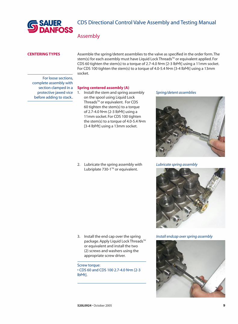
CENTERING TYPES Assemble the spring/detent assemblies to the valve as specified in the order form. The stem(s) for each assembly must have Liquid Lock ThreadsTM or equivalent applied. For CDS 60 tighten the stem(s) to a torque of 2.7-4.0 N•m [2-3 lbf•ft] using a 11mm socket. For CDS 100 tighten the stem(s) to a torque of 4.0-5.4 N•m [3-4 lbf•ft] using a 13mm socket.
Spring/detent assemblies1. Install the stem and spring assembly on the spool using Liquid Lock ThreadsTM or equivalent. For CDS 60 tighten the stem(s) to a torque of 2.7-4.0 N•m [2-3 lbf•ft] using a 11mm socket. For CDS 100 tighten the stem(s) to a torque of 4.0-5.4 N•m [3-4 lbf•ft] using a 13mm socket.
2. Lubricate the spring assembly with Lubriplate 730-1TM or equivalent.
3. Install the end cap over the spring package. Apply Liquid Lock ThreadsTM
or equivalent and install the two (2) screws and washers using the appropriate screw driver.
Screw torque: • CDS 60 and CDS 100 2.7-4.0 N•m [2-3 lbf•ft].
Lubricate spring assembly
Install endcap over spring assembly
For loose sections, complete assembly with
section clamped in a protective jawed vice
before adding to stack..
Spring centered assembly (A)

10 520L0924 • October 2005
CDS Directional Control Valve Assembly and Testing Manual
Assembly
1. Install stem on spool using using Liquid Lock ThreadsTM or equivalent. For CDS 60 tighten the stem(s) to a torque of 2.7-4.0 N•m [2-3 lbf•ft] using a 11mm socket. For CDS 100 tighten the stem(s) to a torque of 4.0-5.4 N•m [3-4 lbf•ft] using a 13mm socket.
2. Fasten cap to spool with two screws and washers. Using a 5/32 hex driver, torque screws to 5.5-8.2 N•m [4-6 lbf•ft].
Install detent assembly
Install spring in detent assembly
Install cover in detent assembly
3 Lubricate the steel balls and spring with LUBRIPLATE 730-1TM or equivalent.
4. Install one ball and the spring into the holes of the end cap.
5. Install second ball on other end of spring.
6 Compress the balls against the spring evenly and slip the sleeve over the end.
Three position detent assembly (B)CENTERING TYPES (continued)
11520L0924 • October 2005
CDS Directional Control Valve Assembly and Testing Manual
Assembly
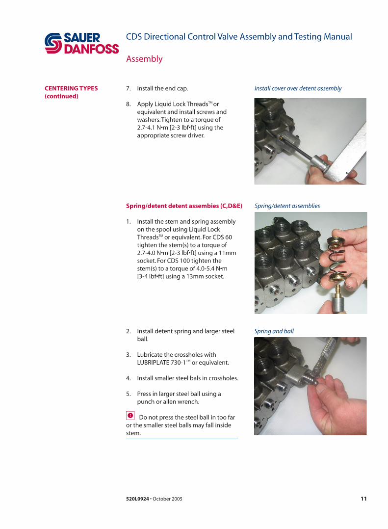
Install cover over detent assembly7. Install the end cap.
8. Apply Liquid Lock ThreadsTM or equivalent and install screws and washers. Tighten to a torque of 2.7-4.1 N•m [2-3 lbf•ft] using the appropriate screw driver.
CENTERING TYPES (continued)
Spring/detent detent assembies (C,D&E) Spring/detent assemblies
2. Install detent spring and larger steel ball.
3. Lubricate the crossholes with LUBRIPLATE 730-1TM or equivalent.
4. Install smaller steel bals in crossholes.
5. Press in larger steel ball using a punch or allen wrench.
Do not press the steel ball in too far or the smaller steel balls may fall inside stem.
1. Install the stem and spring assembly on the spool using Liquid Lock ThreadsTM or equivalent. For CDS 60 tighten the stem(s) to a torque of 2.7-4.0 N•m [2-3 lbf•ft] using a 11mm socket. For CDS 100 tighten the stem(s) to a torque of 4.0-5.4 N•m [3-4 lbf•ft] using a 13mm socket.
Spring and ball

12 520L0924 • October 2005
CDS Directional Control Valve Assembly and Testing Manual
Assembly
Install endcap
3. Install backup washer. ?
Install detent5. Install detent sleeve.
6. Slide the end cap spacer over the detent.
CENTERING TYPES (continued)
Cover extension7. Slide endcap spacer over spool.
8. Install endcap using two screws and washers.
9. Apply Liquid Lock ThreadsTM or equivalent.
10. Torque screws to 2.7-4.1 N•m [2-3 lbf•ft] using the appropriate screw driver.

13520L0924 • October 2005
CDS Directional Control Valve Assembly and Testing Manual
Assembly
Install spring assembly and spool end
1. Install spring assembly and spool end. Use LocktiteTM on spool end. For CDS 60 tighten the stem(s) to a torque of 2.7-4.0 N•m [2-3 lbf•ft] using a 11mm socket. For CDS 100 tighten the stem(s) to a torque of 4.0-5.4 N•m [3-4 lbf•ft] using a 13mm socket.
Spring center/float detent assembly (J)
Spring and ball
Spacer
6. Slide end cap spacer over spool. Slide detent sleeve over spool.
CENTERING TYPES (continued)
2. Install detent spring and larger steel ball.
3. Lubricate the crossholes with LUBRIPLATE 730-1TM or equivalent.
4. Install smaller steel bals in crossholes.
5. Press in larger steel ball using a punch or allen wrench.
Do not press the steel ball in too far or the smaller steel balls may fall inside stem.

14 520L0924 • October 2005
CDS Directional Control Valve Assembly and Testing Manual
Assembly
5. Screw cap on endcap.
Torque screws
Screw on endcap
4. Install the two (2) screws and washers. Apply Liquid Lock ThreadsTM
or equivalent and torque screws to 2.7-4.1 N•m [2-3 lbf•ft] using the appropriate screw driver.
CENTERING TYPES (continued)
Sauer-Danfoss recommends purchasing a complete assembly..
Hydraulic kickout (F)
Install spring assembly (G, H, I) using process similar to (A), page 9.
Spring center assembly (G, H, I)

15520L0924 • October 2005
CDS Directional Control Valve Assembly and Testing Manual
Assembly
AUXILIARY VALVES 1. Assemble the main relief valve into the inlet. Ensure that the O-rings are lubricated. The torque for the relief valve assembly is 41-48 N•m [20-25 lbf•ft], using a 1 inch wrench. For inlet section without the relief valve option, go to next step.
2. Assemble the port relief valve(s) (with and with out anti-cavitation) into the valve stack section(s). Ensure that the O-rings are lubricated. The torque for the port relief valve assembly is 41-48 N•m [20-25 lbf•ft], using a 1 inch wrench.
3. Assemble the plug for the port relief into the valve stack section(s). Ensure that the O-rings are lubricated. The torque for the assembly is 20-27 N•m [15-20 lbf•ft], using a 1 inch hex driver.
4. Assemble pilot operated check valves and flow control valves using the same process used for reliefs.
For sections used without auxiliary valves, check to ensure the correctness of body for function desired.
Auxiliary valve
Flow control piston option
Pilot operated check piston option

16 520L0924 • October 2005
CDS Directional Control Valve Assembly and Testing Manual
Assembly
LOAD CHECK Assemble the load check sections as specified in the order form.
Assemble the load check valves into the valve stack section(s). Ensure that the O-rings are lubricated. Install the check with spring into the valve section, then install the plug. The torque for the plug is 20-27 N•m [15-20 lbf•ft], using a 22 mm wrench (CDS 60), 32 mm wrench (CDS 100).
For assemblies with motor spools in the section, the cavity for a load check will receive a plug. Ensure that the O-rings are lubricated. The torque for the plug is 20-27 N•m [15-20 lbf•ft], using a 22 mm wrench (CDS 60), 32 mm wrench (CDS 100).
Stamp the part number, date code, relief valve setting, build center number on the name plate in the proper locations. Attach the name plate to the inlet section using two (2) drive screws.

17520L0924 • October 2005
CDS Directional Control Valve Assembly and Testing Manual
Assembly
HANDLE ASSEMBLY 1. Install upper and lower pivot assemblies using LocktiteTM. Ensure pivot assemblies are installed equal distance (use a straight edge) . The torque for the relief valve assembly is 40-48 N•m [30-35 lbf•ft], using a 1 inch wrench.
Install pivot assemblies
Assemble handle linkage2. Assemble handle linkage using pins and cotter pins supplied.

18 520L0924 • October 2005
CDS Directional Control Valve Assembly and Testing Manual
Assembly
JOYSTICK ASSEMBLY
Joystick assembly
Joystick assembly attached to sections
2. Assemble joystick pivot assembly. Use LocktiteTM. The torque for the nuts is 40-48 N•m [30-35 lbf•ft], using a 7/16 inch wrench.
3. Bolt joystick assembly to sections using hardware supplied.
Attach joystick handle
Joystick pivot1. Assemble joystick pivot. Use LocktiteTM. The torque for the pivot is 40-48 N•m [30-35 lbf•ft], using a 7/16 in wrench.
4. Attach joystick handle.

19520L0924 • October 2005
CDS Directional Control Valve Assembly and Testing Manual
Assembly
Joystick pivot
Add bushing
1. Assemble joystick pivot using LocktiteTM. Use a straight edge to ensure pivots are equal distance. The torque for the pivot is 40-48 N•m [30-35 lbf•ft], using a 7/16 inch wrench.
2. Add a bushing when installing the bearing. Install washer and nut. Torque nut to 40-48 N•m [30-35 lbf•ft].
Install third bearing
ALTERNATE JOYSTICK ASSEMBLY
Connect pivot plate
3. Install third bearing using long bolt. Install washer and nut. Torque nut to 40-48 N•m [30-35 lbf•ft].
4. Attach pivot plate using washers and nuts provided. Torque nuts to 40-48 N•m [30-35 lbf•ft].

20 520L0924 • October 2005
CDS Directional Control Valve Assembly and Testing Manual
Assembly
CABLE ASSEMBLY 1. Install cable connector. Use LocktiteTM. The torque for the cable connector is 40-48 N•m [30-35 lbf•ft], using a 1 inch wrench.
Install pivot assemblies
Install locknut
Cable end
2. Install locknut on cable.
3. Install cable end.
21520L0924 • October 2005
CDS Directional Control Valve Assembly and Testing Manual
Assembly
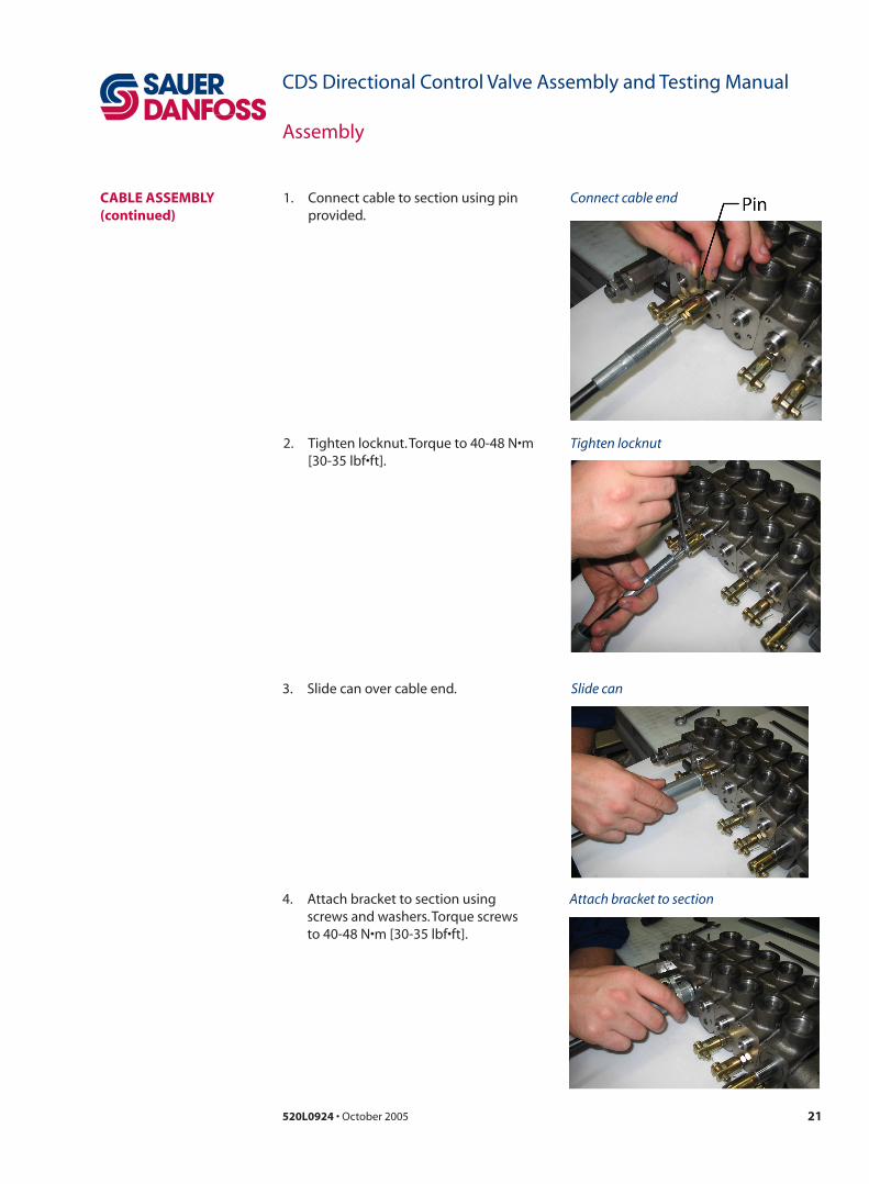
Connect cable end
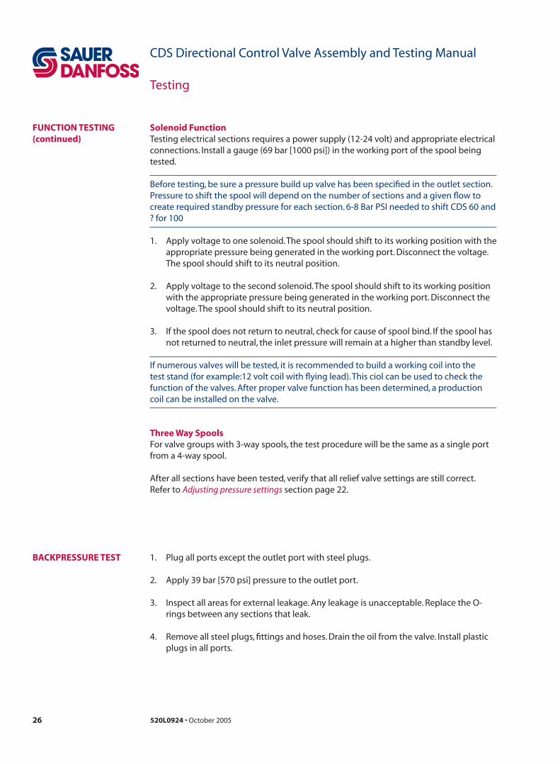
Tighten locknut
1. Connect cable to section using pin provided.
2. Tighten locknut. Torque to 40-48 N•m [30-35 lbf•ft].
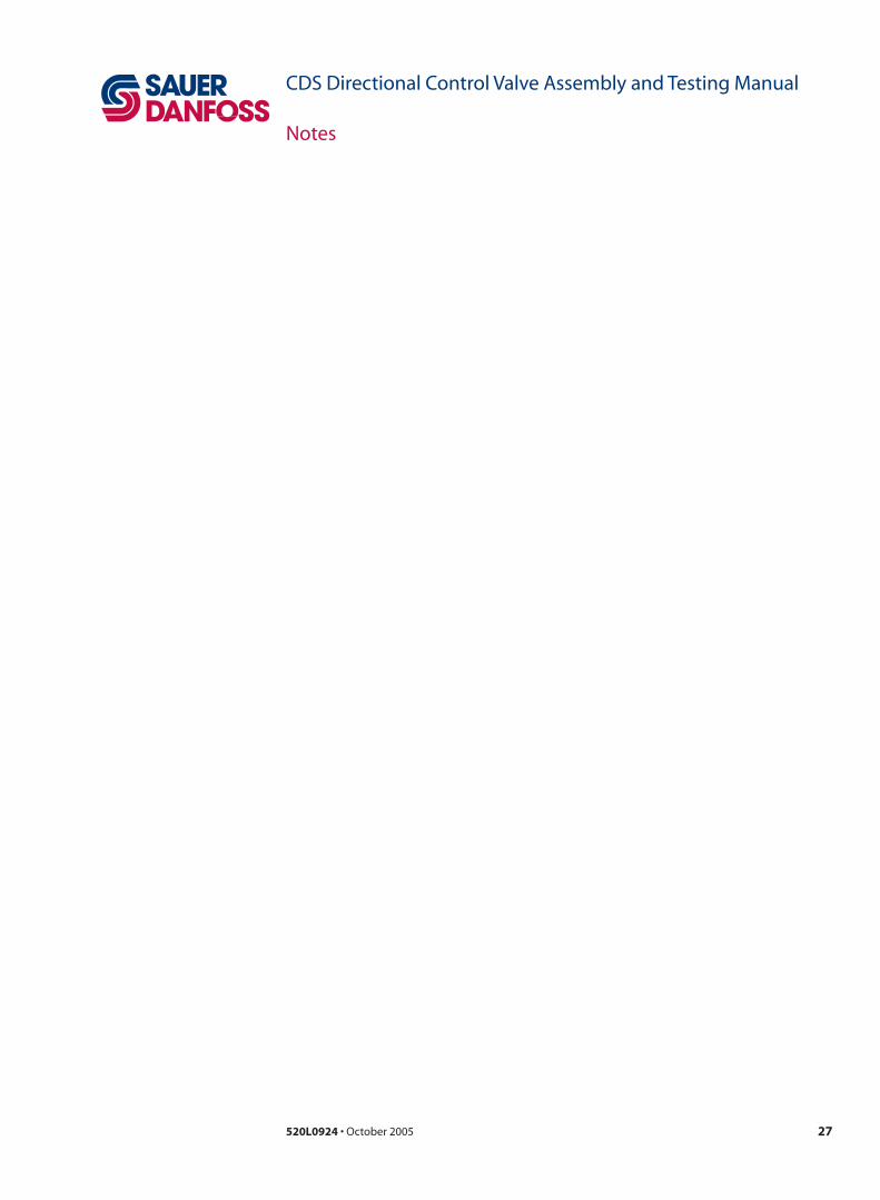
Slide can
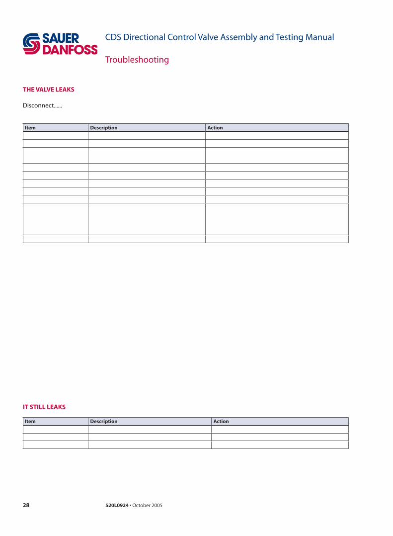
Attach bracket to section
CABLE ASSEMBLY (continued)
3. Slide can over cable end.
4. Attach bracket to section using screws and washers. Torque screws to 40-48 N•m [30-35 lbf•ft].

22 520L0924 • October 2005
CDS Directional Control Valve Assembly and Testing Manual
Testing
OIL AND TEST CONDITIONS
ADJUSTING PRESSURE SETTINGS
• Pressure required: Up to 207 bar [3000 psi] on a regulated line• Flow required: Minimum of 80 liters/min [10-15 USgal/min] or stack flow and pressure requirements• Oil type: Mobil DTE 24 or equvilant• Oil temperature: 43°C +/- 3°C [110°F +/- 5°F]• Oil cleanliness level: ISO 19/16 (10 micron or better; suction and return)• 12/24 Volt DC power supply and digital volt meter• Remote joystick
Main relief valveTest the main inlet pressure relief valve by applying oil pressure on the pressure port of the inlet section.
1. Install a 69 bar [1000 psi] gauge in the pressure port of the inlet section.
2. Connect the tank port to the tank.
3. Shift one of the spools in a section to block free flow through the valve.
4. Set the main Inlet relief of the valve assembly to customer required specification. Refer to Sauer-Danfoss publication CDS stack valve assembly order form 520Lxxx for relief settings.
Work port relief valveTest the work port pressure relief valves by applying oil pressure on the work port.
1. Install a 69 bar [1000 psi] gauge in the work port of the selected section.
2. Connect the tank port to the tank.
3. Block all other ports off with steel plugs. 4. Set the port relief of the valve assembly according to Sauer-Danfoss publication CDS
stack valve assembly order form 520Lxxx.
Adjusting main/port relief valvesAdjust the main/port relief valves by loosening the lock nut (17 mm) and turning the adjusting screw (11 mm). Turning the adjusitng screw clockwise raises the relief pressure and turning counterclockwise lowers the relief pressure. Retest the relief pressure. Continue to turn the adjusting screw, lock the locknut, and retest until the desired setting is reached.
Non-Adjustable relief’s are adjusted by adding shim or shims of various thickness until the desired setting is obtained.
Connect the valve to a test stand consisting of a hydraulic pump, appropriate hoses and fittings, appropriate gauges, temperature control, power supply, and an adequate filter and tank. The minimum specifications for the test stand are listed below.

23520L0924 • October 2005
CDS Directional Control Valve Assembly and Testing Manual
Testing
Load check leakage
See note on oil and test conditions page 22.
Apply 69 bar [1000 psi] to the work port opposite handle assembly. Plug all ports except work port and Pressure port. Shift spool slightly to prime the passage way before starting leakage test.Shift the spool in the full out position (towards operator) to check for leakage. Maximum leakage allowed out the outlet port is 80 cc [5 cubic inches] per minute (22 cc [1.4 cubic inches] in 10 seconds).
Leakage testing apparatus
Work port leakage
Plug all ports except work port to be tested and tank port. Apply 69 bar [1000 psi] to the work port of each section. Shift spool slightly to prime the passage way before starting the test. Check for leakage out by using goose neck style tubing (shown below) in the outlet port. With the spool in the neutral position,pressurize the work port and check leakage rate for 10 seconds. Check a minimum of twice per port. Rotate spool 180 degrees befor to checking the second time. Maximum leakage allowed out the outlet port is 16 cc [1 cubic inch] per minute (2.6 cc [0.16 cubic inch] for 10 seconds).
Leakage testing
LEAKAGE TESTING

24 520L0924 • October 2005
CDS Directional Control Valve Assembly and Testing Manual
Testing
FUNCTION TESTING Function testing insures the correct dynamic manual operation of the CDS stack valve assembly. Perform this test after completing the pressure adjustments. Test each section of the assembly. Connect each section to a hydraulic cylinder to perform the test. Install a gauge (69 bar [1000 psi]) in the cylinder extension and retraction lines.
1. Connect the valve to pressure and tank. Plug all work ports except the ports from the section to be tested.
2. Connect the A port of the valve to the rod end of the cylinder and the B port to the base end of the cylinder.
3. Shift the control lever of the section in (towards the valve) and observe cylinder retraction. Shift the same control lever out (away from the valve) and observe cylinder extension. Repeat several times.
On valve groups with lever(s) on the B side, the cylinder movement will be opposite.
4. Check the spool travel smoothness in both directions. Sticky spools indicate problems with the O-rings. Replace the section if spool travel is not smooth.
5. Check the metering of the spool in both directions. The speed of cylinder extension/retraction is controllable by metering the spool.
6. Check each work port for the ability to build full system pressure, as limited by the port relief if present. Hold the lever at full stroke after the cylinder reaches the end of the stroke. Line pressure should not go above relief setting.
Spring Center Function 1. Shift the spool manually in one direction and let go of the control lever. The valve
should center itself, with no hesitation. If the control lever sticks in any position, check for binding of the spool.
2. Check spool return in both directions. If the spool sticks, replace the section.
Detent Functions1. Shift the spool in one direction manually. Let go of the control lever. The spool
should remain in shifted position.
2. Check detent function in both directions. If the control lever moves back in neutral position, check for cause of the spool movement. Repair or replace detent function.

25520L0924 • October 2005
CDS Directional Control Valve Assembly and Testing Manual
Testing
Float FunctionsSpools with the detent float option have four postions. Spring center for three positions and detent for the fourth. The fourth position (float) may be detented in the extreme in or out position of the spool travel.
The difference between the spring center function and this fourth postion (float) ,is that the work port and inlet flow dumps to tank once shifted into detent.
1. Shift the spool to detent position.The spool must remain in detent when the handle is released.
2. If the control lever goes back to neutral after being moved to detent, check for the cause of the spool movement. Rebuild or replace the detent function.
Pneumatic Function1. Apply air pressure to actuator. The spool will shift with 4-12 bar [58-174 psi] air
pressure applied for each direction. Shifting pressure will vary pending size of valve (CDS 60/100), valve flow, and pressure requirements.
2. Remove air pressure. The spool should return to neutral. Check function in both directions. If the spool does not return to neutral, check for cause of spool bind. Replace actuator. Replace section if necessary.
Hydraulic Function1. Apply hydraulic pressure to actuator. The spool will shift with at 35-100 bar [116-
1450 psi] pilot pressure applied for each direction. Shifting pressure will vary pending size of valve (CDS 60/100) and valve flow and pressure requirements.
2. Remove pilot pressure. The spool should return to neutral. Check function in both directions. If the spool does not return to neutral, check for cause of spool bind. Replace actuator. Replace section if necessary.
FUNCTION TESTING (continued)
26 520L0924 • October 2005
CDS Directional Control Valve Assembly and Testing Manual
Testing
BACKPRESSURE TEST 1. Plug all ports except the outlet port with steel plugs.
2. Apply 39 bar [570 psi] pressure to the outlet port.
3. Inspect all areas for external leakage. Any leakage is unacceptable. Replace the O-rings between any sections that leak.
4. Remove all steel plugs, fittings and hoses. Drain the oil from the valve. Install plastic plugs in all ports.
Solenoid Function Testing electrical sections requires a power supply (12-24 volt) and appropriate electrical connections. Install a gauge (69 bar [1000 psi]) in the working port of the spool being tested.
Before testing, be sure a pressure build up valve has been specified in the outlet section. Pressure to shift the spool will depend on the number of sections and a given flow to create required standby pressure for each section. 6-8 Bar PSI needed to shift CDS 60 and ? for 100
1. Apply voltage to one solenoid. The spool should shift to its working position with the appropriate pressure being generated in the working port. Disconnect the voltage. The spool should shift to its neutral position.
2. Apply voltage to the second solenoid. The spool should shift to its working position with the appropriate pressure being generated in the working port. Disconnect the voltage. The spool should shift to its neutral position.
3. If the spool does not return to neutral, check for cause of spool bind. If the spool has not returned to neutral, the inlet pressure will remain at a higher than standby level.
If numerous valves will be tested, it is recommended to build a working coil into the test stand (for example:12 volt coil with flying lead). This ciol can be used to check the function of the valves. After proper valve function has been determined, a production coil can be installed on the valve.
Three Way SpoolsFor valve groups with 3-way spools, the test procedure will be the same as a single port from a 4-way spool.
After all sections have been tested, verify that all relief valve settings are still correct. Refer to Adjusting pressure settings section page 22.
FUNCTION TESTING (continued)
27520L0924 • October 2005
CDS Directional Control Valve Assembly and Testing Manual
Notes
28 520L0924 • October 2005
CDS Directional Control Valve Assembly and Testing Manual
Troubleshooting
Item Description Action
THE VALVE LEAKS
Disconnect......
Item Description Action
IT STILL LEAKS

29520L0924 • October 2005
CDS Directional Control Valve Assembly and Testing Manual
Troubleshooting
Item Description Action
RELIEF DOESN’T WORK
Item Description Action
STICKY SPOOL
Item Description Action
CABLE BINDS

30 BLN-10263 • 520L0924 • October 2005
CDS Stack Valve Assembly and Testing Manual
Appendix
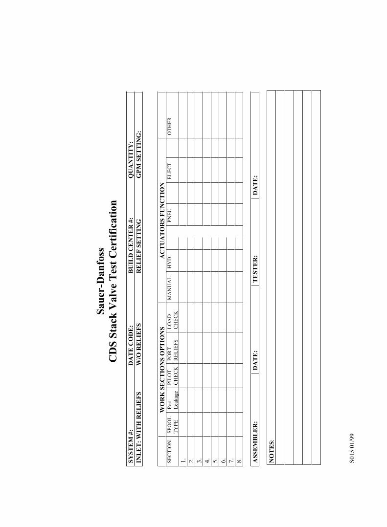
APPENDIX A TESTING CERTIFICATION FORM
The following page contains the CDS stack valve test certification form.
A copy of the certification must be sent to the TST at Sauer-Danfoss, Easley, SC.
Fax number 864-XXX-XXXX.
S015
01/
99
Saue
r-D
anfo
ssC
DS
Stac
k V
alve
Tes
t C
erti
fica
tion
SYST
EM
#:
DA
TE
CO
DE
: B
UIL
D C
EN
TE
R #
: Q
UA
NT
ITY
: IN
LE
T:
WIT
H R
EL
IEF
S W
/O R
EL
IEF
S R
EL
IEF
SE
TT
ING
G
PM
SE
TT
ING
:
WO
RK
SE
CT
ION
S O
PT
ION
S A
CT
UA
TO
RS
FU
NC
TIO
N
SE
CTI
ON
SPO
OL
TYPE
Port
Leak
age
PILO
TC
HEC
KPO
RT
REL
IEFS
LOA
DC
HEC
KM
AN
UA
L H
YD
.
PN
EU
EL
ECT
O
THER
1.
2.
3.
4.
5.
6.
7.
8.
ASS
EM
BL
ER
: D
AT
E:
TE
STE
R:
DA
TE
:
NO
TE
S:

Sauer-Danfoss Mobile Power and Control Systems– Market Leaders Worldwide
Sauer-Danfoss is a comprehensive supplier providing complete systems to the global mobile market.
Sauer-Danfoss serves markets such as agriculture, construction, road building, material handling, municipal, forestry, turf care, and many others.
We offer our customers optimum solutions for their needs and develop new products and systems in close cooperation and partnership with them.
Sauer-Danfoss specializes in integrating a full range of system components to provide vehicle designers with the most advanced total system design.
Sauer-Danfoss provides comprehensive worldwide service for its products through an extensive network of Authorized Service Centers strategically located in all parts of the world.
Sauer-Danfoss (US) Company2800 East 13th StreetAmes, IA 50010, USAPhone: +1 515 239-6000, Fax: +1 515 239 6618
Sauer-Danfoss GmbH & Co. OHGPostfach 2460, D-24531 NeumünsterKrokamp 35, D-24539 Neumünster, GermanyPhone: +49 4321 871-0, Fax: +49 4321 871 122
Sauer-Danfoss ApSDK-6430 Nordborg, DenmarkPhone: +45 7488 4444, Fax: +45 7488 4400
www.sauer-danfoss.com
OUR PRODUCTS
Hydrostatic transmissions
Hydraulic power steering
Electric power steering
Electrohydraulic power steering
Closed and open circuit axial piston pumps and motors
Gear pumps and motors
Bent axis motors
Orbital motors
Transit mixer drives
Planetary compact gears
Proportional valves
Directional spool valves
Cartridge valves
Hydraulic integrated circuits
Hydrostatic transaxles
Integrated systems
Fan drive systems
Electrohydraulics
Microcontrollers and software
Electric motors and inverters
Joysticks and control handles
Displays
Sensors
520L0924 • October 2005