cds g3 and the pcm 112 - 2f - pcm 112 fault tables
TRANSCRIPT
CDS G3 and the PCM 112Section 2F - PCM 112 Fault Tables
Table of Contents
Universal Fault Codes........................................................2F-2 PCM 112 Fault List.............................................................2F-5
PCM 112 Fault Tables
90-8M0086483 FEBRUARY 2015 eng Page 2F-1
2F

Universal Fault CodesThe PCM 112 is the first Mercury control module to adopt universal fault codes. These codes will help ensure uniformity in faultreporting in this and future control modules. It will also help ensure that boat operators will receive consistent information andinstructions, such as Service Engine Soon, Reduce Engine Speed, and others in response to specific faults.For CDS G3 users, this means that instead of seeing a fault such as MAP_Angle_RangeLow, the fault will now appear as 402—Manifold pressure sensor 1 (Angle Based Sampling), 25, The input circuit for the sensor is below the valid limit.Refer to the screenshot below for more examples.
An active fault list example (Actual screen appearance may vary)a - Fault code (the affected component)b - Type code (how it was affected)c - Fault code descriptiond - Fault type code description
In the last line of this example, component 203, fuel injector circuit 3, had a fault type 16, meaning that the PCM 112 is unableto output a signal to the device. This could indicate a faulty fuel injector, or in this case, where the same fault is affectingmultiple injector and other components, likely indicates a more widespread fault, such as an unplugged harness, issues with apower supply, or some other systemic issue.There are as many fault codes as there are components on engines that use universal fault codes, and the PCM 112 only usesa small subset of these. There are 27 fault types, only a few of which will be relevant to any single component. Any‑applicationspecific notes will be included in the diagnostic manual.
UniversalFailureTypeNumber
Universal FailureCondition Description Suggested Approach/Notes
1 Output open circuit
The output signal to the device from thePCM is an open circuit or has too muchresistance. On the PCM 112 this is onlyused with the wide‑band precatalyst (S1)oxygen sensors.
Refer to the wiring diagrams and check theharness for continuity between the PCM andthe sensor. If continuity exists, replace the O2sensor with a known good sensor and clearthe faults. If it returns, the issue is with thePCM.
a b c d
56697
PCM 112 Fault Tables
Page 2F-2 90-8M0086483 FEBRUARY 2015 eng
UniversalFailureTypeNumber
Universal FailureCondition Description Suggested Approach/Notes
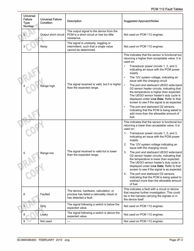
2 Output short circuitThe output signal to the device from thePCM is a short circuit or has too littleresistance.
Not used on PCM 112 engines.
3 NoisyThe signal is unsteady, toggling orintermittent, such that a single valuecannot be determined.
Not used on PCM 112 engines.
4 Range high The signal received is valid, but it is higherthan the expected range.
This indicates that the sensor is functional butreturning a higher than acceptable value. It isused on:• Transducer power circuits 1, 2, and 3,
indicating an issue with the PCM powersupply.
• The 12V system voltage, indicating anissue with the charging circuit
• The port and starboard UEGO wide‑bandO2 sensor heater circuits, indicating thatthe temperature is higher than expected.The UEGO sensor heater's duty cycle isdisplayed under Live Data. Refer to thatscreen to see if the signal is as expected.
• The port and starboard O2 sensors,indicating that the PCM is being asked toadd more than the allowable amount offuel.
5 Range low The signal received is valid but is lowerthan the expected range.
This indicates that the sensor is functional butreturning a lower than acceptable value. It isused on:1. Transducer power circuits 1, 2, and 3,
indicating an issue with the PCM powersupply.
2. The 12V system voltage indicating anissue with the charging circuit.
3. The port and starboard UEGO wide‑bandO2 sensor heater circuits, indicating thatthe temperature is lower than expected.The UEGO sensor heater's duty cycle isdisplayed under Live Data. Refer to thatscreen to see if the signal is as expected.
4. The port and starboard O2 sensors,indicating that the PCM is being asked tosubtract more than the allowable amountof fuel.
6 FaultedThe device, hardware, calculation, orprocess has failed a rationality check orhas detected a fault.
This indicates a fault with a circuit or devicethat requires further investigation. This couldbe in the harness carrying the signals or inthe device itself.
7 Dirty The signal following a switch is below theexpected value. Not used on PCM 112 engines.
8 Leaky The signal following a switch is above theexpected value. Not used on PCM 112 engines.
9 Not used — Not used on PCM 112 engines.
PCM 112 Fault Tables
90-8M0086483 FEBRUARY 2015 eng Page 2F-3

UniversalFailureTypeNumber
Universal FailureCondition Description Suggested Approach/Notes
10 Rich Too much fuel was detected relative to theamount of air.
This is used with the port and starboard postO2 (S2) oxygen sensors in emission‑controlengines. It may indicate that a rich conditionexists or that the O2 sensor is stuck readingrich.
11 Lean Too little fuel was detected relative to theamount of air.
This is used with the port and starboard postO2 (S2) oxygen sensors in emission‑controlengines. It may indicate that a lean conditionexists or that the O2 sensor is stuck readinglean.
12 Disabled Due to conditions present, the device hasbeen disabled Not used on PCM 112 engines.
13 Communicationfailure
Communication with the device has beenlost. Not used on PCM 112 engines.
14 Response The device is not responding properly. Not used on PCM 112 engines.
15 Keyup diagnosticfailed
The device has run a key up diagnosticand has detected a problem. Not used on PCM 112 engines.
16 Output fault The PCM has detected a problem whentrying to output a signal to this device.
This fault is used with the ignition coils, fuelinjectors, O2 sensor heaters, and variousother actuators. It indicates an actuator is notturning on or off as expected.
17 Out of rangeThe signal or result is outside theexpected range but there is not enoughinformation to indicate high or low.
This fault Is used for the TMAP's barometerrange and indicates that the pressure readingis outside of an expected operating range,such as 6,500 ft. above sea level. The sensoris working, but is not working correctly, or anunusual vacuum situation may exist.
18 Not converged The algorithm cannot reach a conclusion. Not used on PCM 112 engines.
19 Not performed Conditions are such that the test cannotbe performed. Not used on PCM 112 engines.
20 Overheat A temperature sensor value is higher thannormal.
This is used to indicate an overheat conditionin the engine coolant, or port or starboardexhaust coolant.
21 Too low Relative to a specified threshold, the valueis too low.
This indicates a low pressure condition existswith the sea pump pressure, engine oilpressure, or drive lube.
22 Too high Relative to a specified threshold, the valueis too high.
This fault is only used with the sea pumppressure.
23 Is active Indicates a particular state or conditionexists.
This indicates that the referenced failure typecurrently exists. It is used with severalconditions, such as emergency stop (hasbeen activated), Guardian (is currentlyactive), and others.
24 Input high The input circuit for the sensor is abovethe valid limit. Indicates an open or shorted sensor circuit.
25 Input low The input circuit for the sensor is belowthe valid limit. indicates an open or shorted sensor circuit.
26 Input open circuitThe input signal from the device to thePCM is an open circuit or has too muchresistance.
Used only on postcatalyst O2 sensors.
PCM 112 Fault Tables
Page 2F-4 90-8M0086483 FEBRUARY 2015 eng

UniversalFailureTypeNumber
Universal FailureCondition Description Suggested Approach/Notes
27 Input short circuitThe input signal from the device to thePCM is a short circuit or has too littleresistance.
Used only on precatalyst O2 sensors.
PCM 112 Fault List
FaultNumber Description
FailureType
NumberFailure Types Notes
101 Ignition circuit 1 16 Output fault Check circuits, coils, high tensionleads, spark plugs
102 Ignition circuit 2 16 Output fault Check circuits, coils, high tensionleads, spark plugs
103 Ignition circuit 3 16 Output fault Check circuits, coils, high tensionleads, spark plugs
104 Ignition circuit 4 16 Output fault Check circuits, coils, high tensionleads, spark plugs
201 Fuel injector circuit 1 16 Output fault Check the PCM‑to‑injector #1 circuitor for an open injector coil.
202 Fuel injector circuit 2 16 Output fault Check the PCM‑to‑injector #2 circuitor for an open injector coil.
203 Fuel injector circuit 3 16 Output fault Check the PCM‑to‑injector #3 circuitor for an open injector coil.
204 Fuel injector circuit 4 16 Output fault Check the PCM‑to‑injector #4 circuitor for an open injector coil.
205 Fuel injector circuit 5 16 Output fault Check the PCM‑to‑injector #5 circuitor for an open injector coil.
206 Fuel injector circuit 6 16 Output fault Check the PCM‑to‑injector #6 circuitor for an open injector coil.
207 Fuel injector circuit 7 16 Output fault Check the PCM‑to‑injector #7 circuitor for an open injector coil.
208 Fuel injector circuit 8 16 Output fault Check the PCM‑to‑injector #8 circuitor for an open injector coil.
301 Throttle position sensor A24 Input high A sensor or sensor wire is shorted to
5V.
25 Input low A sensor or sensor wire is open orshorted to ground.
302 Throttle position sensor B24 Input high A sensor or sensor wire is open or
shorted to ground.
25 Input low A sensor or sensor wire is shorted to5V.
311 Throttle position sensors A and B 6 Faulted Both sensors are faulted. Possibleissue with transducer power.
331 Throttle position sensors A and Bdifference 6 Faulted If TPS 1 reads X, then TPS 2 should
read Y; one of them is incorrect.
341 Throttle position sensor adapt A 6 Faulted
DTS engine: TPS 1 did not indicatethat the throttle plate moved to thespecified closed throttle positionduring the engine shut down process.
PCM 112 Fault Tables
90-8M0086483 FEBRUARY 2015 eng Page 2F-5
FaultNumber Description
FailureType
NumberFailure Types Notes
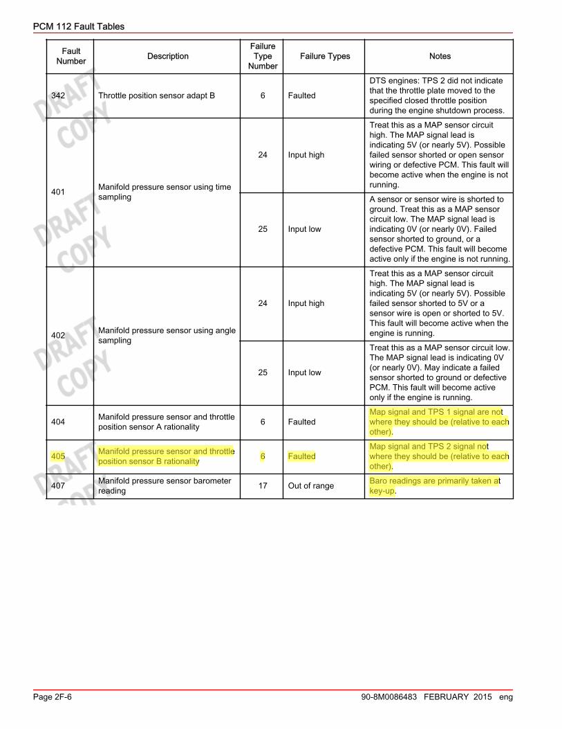
342 Throttle position sensor adapt B 6 Faulted
DTS engines: TPS 2 did not indicatethat the throttle plate moved to thespecified closed throttle positionduring the engine shutdown process.
401 Manifold pressure sensor using timesampling
24 Input high
Treat this as a MAP sensor circuithigh. The MAP signal lead isindicating 5V (or nearly 5V). Possiblefailed sensor shorted or open sensorwiring or defective PCM. This fault willbecome active when the engine is notrunning.
25 Input low
A sensor or sensor wire is shorted toground. Treat this as a MAP sensorcircuit low. The MAP signal lead isindicating 0V (or nearly 0V). Failedsensor shorted to ground, or adefective PCM. This fault will becomeactive only if the engine is not running.
402 Manifold pressure sensor using anglesampling
24 Input high
Treat this as a MAP sensor circuithigh. The MAP signal lead isindicating 5V (or nearly 5V). Possiblefailed sensor shorted to 5V or asensor wire is open or shorted to 5V.This fault will become active when theengine is running.
25 Input low
Treat this as a MAP sensor circuit low.The MAP signal lead is indicating 0V(or nearly 0V). May indicate a failedsensor shorted to ground or defectivePCM. This fault will become activeonly if the engine is running.
404 Manifold pressure sensor and throttleposition sensor A rationality 6 Faulted
Map signal and TPS 1 signal are notwhere they should be (relative to eachother).
405 Manifold pressure sensor and throttleposition sensor B rationality 6 Faulted
Map signal and TPS 2 signal notwhere they should be (relative to eachother).
407 Manifold pressure sensor barometerreading 17 Out of range Baro readings are primarily taken at
key‑up.
PCM 112 Fault Tables
Page 2F-6 90-8M0086483 FEBRUARY 2015 eng
FaultNumber Description
FailureType
NumberFailure Types Notes
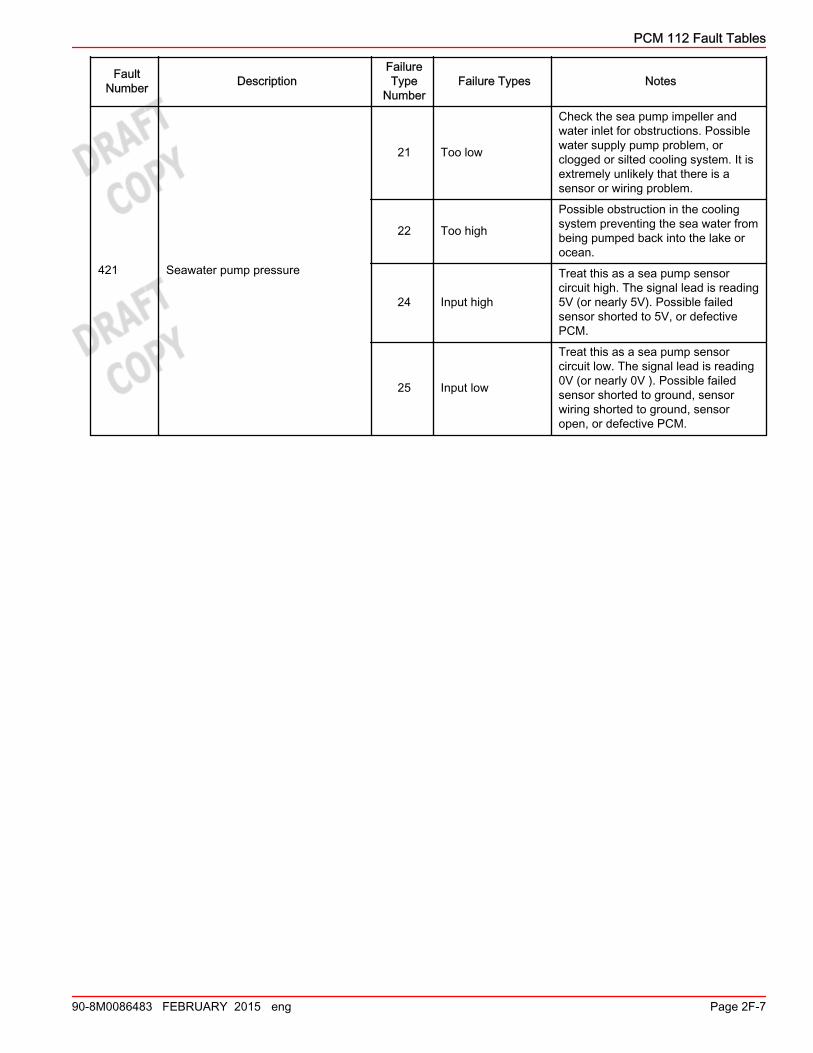
421 Seawater pump pressure
21 Too low
Check the sea pump impeller andwater inlet for obstructions. Possiblewater supply pump problem, orclogged or silted cooling system. It isextremely unlikely that there is asensor or wiring problem.
22 Too high
Possible obstruction in the coolingsystem preventing the sea water frombeing pumped back into the lake orocean.
24 Input high
Treat this as a sea pump sensorcircuit high. The signal lead is reading5V (or nearly 5V). Possible failedsensor shorted to 5V, or defectivePCM.
25 Input low
Treat this as a sea pump sensorcircuit low. The signal lead is reading0V (or nearly 0V ). Possible failedsensor shorted to ground, sensorwiring shorted to ground, sensoropen, or defective PCM.
PCM 112 Fault Tables
90-8M0086483 FEBRUARY 2015 eng Page 2F-7

FaultNumber Description
FailureType
NumberFailure Types Notes
431 Oil pressure
21 Too low
Indicates a problem with the engine'spressurized lubrication system. Do notoverlook the oil level being too high,as that will cause aerated oil, whichwill result in low oil pressure. Othercommon problems are:• Oil level in engine is too low.• Incorrect grade of oil.• Diluted oil (with gasoline).• Worn engine or cam bearings.• Clogged pump pickup screen.• An out‑of‑calibration oil pressure
sensor.• Sensor is bad but not shorted or
open.• There is a mechanical problem in
the oil pressure system.
24 Input high
Treat this as an oil pressure sensorcircuit high. The signal lead is reading5V (or nearly 5V).• Check the sensor and sensor
wiring for shorts to 5V.• Possible defective PCM.• Sensor is shorted internally.• A sensor wire may be shorted to
5V.
25 Input low
Treat this as an oil pressure sensorcircuit low. The signal lead is reading0V (or nearly 0V ). Check the sensorand sensor wiring for opens andshorts.• Sensor is open or shorted
internally.• A sensor wire is open or shorted
to ground.• Possible defective PCM.
PCM 112 Fault Tables
Page 2F-8 90-8M0086483 FEBRUARY 2015 eng
FaultNumber Description
FailureType
NumberFailure Types Notes
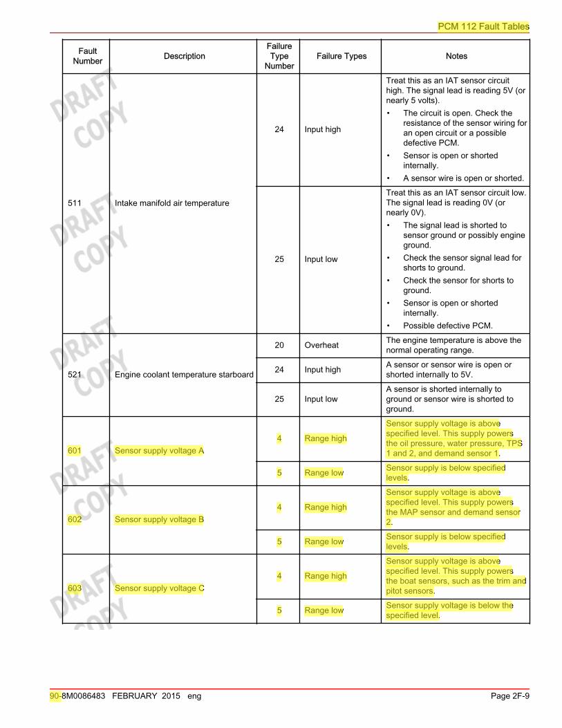
511 Intake manifold air temperature
24 Input high
Treat this as an IAT sensor circuithigh. The signal lead is reading 5V (ornearly 5 volts).• The circuit is open. Check the
resistance of the sensor wiring foran open circuit or a possibledefective PCM.
• Sensor is open or shortedinternally.
• A sensor wire is open or shorted.
25 Input low
Treat this as an IAT sensor circuit low.The signal lead is reading 0V (ornearly 0V).• The signal lead is shorted to
sensor ground or possibly engineground.
• Check the sensor signal lead forshorts to ground.
• Check the sensor for shorts toground.
• Sensor is open or shortedinternally.
• Possible defective PCM.
521 Engine coolant temperature starboard
20 Overheat The engine temperature is above thenormal operating range.
24 Input high A sensor or sensor wire is open orshorted internally to 5V.
25 Input lowA sensor is shorted internally toground or sensor wire is shorted toground.
601 Sensor supply voltage A4 Range high
Sensor supply voltage is abovespecified level. This supply powersthe oil pressure, water pressure, TPS1 and 2, and demand sensor 1.
5 Range low Sensor supply is below specifiedlevels.
602 Sensor supply voltage B4 Range high
Sensor supply voltage is abovespecified level. This supply powersthe MAP sensor and demand sensor2.
5 Range low Sensor supply is below specifiedlevels.
603 Sensor supply voltage C4 Range high
Sensor supply voltage is abovespecified level. This supply powersthe boat sensors, such as the trim andpitot sensors.
5 Range low Sensor supply voltage is below thespecified level.
PCM 112 Fault Tables
90-8M0086483 FEBRUARY 2015 eng Page 2F-9
FaultNumber Description
FailureType
NumberFailure Types Notes
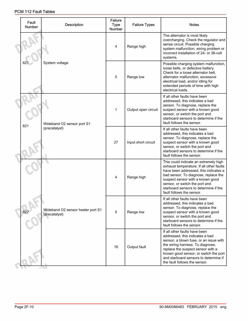
621 System voltage
4 Range high
The alternator is most likelyovercharging. Check the regulator andsense circuit. Possible chargingsystem malfunction, wiring problem orincorrect installation of 24‑ or 36‑voltsystems.
5 Range low
Possible charging system malfunction,loose belts, or defective battery.Check for a loose alternator belt,alternator malfunction, excessiveelectrical load, and/or idling forextended periods of time with highelectrical loads.
821 Wideband O2 sensor port S1(precatalyst)
1 Output open circuit
If all other faults have beenaddressed, this indicates a badsensor. To diagnose, replace thesuspect sensor with a known goodsensor, or switch the port andstarboard sensors to determine if thefault follows the sensor.
27 Input short circuit
If all other faults have beenaddressed, this indicates a badsensor. To diagnose, replace thesuspect sensor with a known goodsensor, or switch the port andstarboard sensors to determine if thefault follows the sensor.
822 Wideband O2 sensor heater port S1(precatalyst)
4 Range high
This could indicate an extremely highexhaust temperature. If all other faultshave been addressed, this indicates abad sensor. To diagnose, replace thesuspect sensor with a known goodsensor, or switch the port andstarboard sensors to determine if thefault follows the sensor.
5 Range low
If all other faults have beenaddressed, this indicates a badsensor. To diagnose, replace thesuspect sensor with a known goodsensor, or switch the port andstarboard sensors to determine if thefault follows the sensor.
16 Output fault
If all other faults have beenaddressed, this indicates a badsensor, a blown fuse, or an issue withthe wiring harness. To diagnose,replace the suspect sensor with aknown good sensor, or switch the portand starboard sensors to determine ifthe fault follows the sensor.
PCM 112 Fault Tables
Page 2F-10 90-8M0086483 FEBRUARY 2015 eng

FaultNumber Description
FailureType
NumberFailure Types Notes
841 Wideband O2 sensor starboard S1(precatalyst)
1 Output open circuit
If all other faults have beenaddressed, this indicates a badsensor. To diagnose, replace thesuspect sensor with a known goodsensor, or switch the port andstarboard sensors to determine if thefault follows the sensor.
27 Input short circuit
If all other faults have beenaddressed, this indicates a badsensor. To diagnose, replace thesuspect sensor with a known goodsensor, or switch the port andstarboard sensors to determine if thefault follows the sensor.
842 Wideband O2 sensor heaterstarboard S1 (precatalyst)
4 Range high
This could indicate an extremely highexhaust temperature. If all other faultshave been addressed, this indicates abad sensor. To diagnose, replace thesuspect sensor with a known goodsensor, or switch the port andstarboard sensors to determine if thefault follows the sensor.
5 Range low
If all other faults have beenaddressed, this indicates a badsensor. To diagnose, replace thesuspect sensor with a known goodsensor, or switch the port andstarboard sensors to determine if thefault follows the sensor.
16 Output fault
If all other faults have beenaddressed, this indicates a badsensor, a blown fuse, or an issue withthe wiring harness. To diagnose,replace the suspect sensor with aknown good sensor, or switch the portand starboard sensors to determine ifthe fault follows the sensor.
PCM 112 Fault Tables
90-8M0086483 FEBRUARY 2015 eng Page 2F-11

FaultNumber Description
FailureType
NumberFailure Types Notes
851 O2 sensor port S2 (postcatalyst)
10 Rich
Check the PCM‑to‑sensor circuit. Todiagnose, replace the suspect sensorwith a known good sensor, or switchthe port and starboard sensors todetermine if the fault follows thesensor.
11 Lean
Part of monitoring test. Check thePCM‑to‑sensor circuit. To diagnose,replace the suspect sensor with aknown good sensor, or switch the portand starboard sensors to determine ifthe fault follows the sensor.
24 Input high
Check the PCM‑to‑sensor circuit. Todiagnose, replace the suspect sensorwith a known good sensor, or switchthe port and starboard sensors todetermine if the fault follows thesensor.
25 Input low
Check the PCM‑to‑sensor circuit. Todiagnose, replace the suspect sensorwith a known good sensor, or switchthe port and starboard sensors todetermine if the fault follows thesensor.
26 Input open circuit
Check the PCM‑to‑sensor circuit. Todiagnose, replace the suspect sensorwith a known good sensor, or switchthe port and starboard sensors todetermine if the fault follows thesensor.
852 O2 sensor heater port S2(postcatalyst) 16 Output fault Check the fuse and PCM‑to‑heater
circuit.
PCM 112 Fault Tables
Page 2F-12 90-8M0086483 FEBRUARY 2015 eng

FaultNumber Description
FailureType
NumberFailure Types Notes
871 O2 sensor starboard S2 (postcatalyst)
10 Rich
Check the PCM‑to‑sensor circuit. Todiagnose, replace the suspect sensorwith a known good sensor, or switchthe port and starboard sensors todetermine if the fault follows thesensor.
11 Lean
Part of monitoring test. Check thePCM‑to‑sensor circuit. To diagnose,replace the suspect sensor with aknown good sensor, or switch the portand starboard sensors to determine ifthe fault follows the sensor.
24 Input high
Check the PCM‑to‑sensor circuit. Todiagnose, replace the suspect sensorwith a known good sensor, or switchthe port and starboard sensors todetermine if the fault follows thesensor.
25 Input low
Check the PCM‑to‑sensor circuit. Todiagnose, replace the suspect sensorwith a known good sensor, or switchthe port and starboard sensors todetermine if the fault follows thesensor.
26 Input open circuit
Check the PCM‑to‑sensor circuit. Todiagnose, replace the suspect sensorwith a known good sensor, or switchthe port and starboard sensors todetermine if the fault follows thesensor.
872 O2 sensor heater starboard S2(postcatalyst) 16 Output fault
Check the fuse and PCM‑to‑heatercircuit. To diagnose, replace thesuspect sensor with a known goodsensor, or switch the port andstarboard sensors to determine if thefault follows the sensor.
901 Short term fuel trim starboard
4 Range highThe PCM has had to add too muchfuel trying to get the correct O2reading.
5 Range lowThe PCM has had to remove toomuch fuel trying to get the correct O2reading.
902 Short term fuel trim port
4 Range highThe PCM has had to add too muchfuel trying to get the correct O2reading.
5 Range lowThe PCM has had to add too muchfuel trying to get the correct O2reading.
PCM 112 Fault Tables
90-8M0086483 FEBRUARY 2015 eng Page 2F-13
FaultNumber Description
FailureType
NumberFailure Types Notes
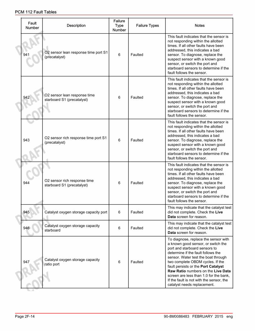
941 O2 sensor lean response time port S1(precatalyst) 6 Faulted
This fault indicates that the sensor isnot responding within the allottedtimes. If all other faults have beenaddressed, this indicates a badsensor. To diagnose, replace thesuspect sensor with a known goodsensor, or switch the port andstarboard sensors to determine if thefault follows the sensor.
942 O2 sensor lean response timestarboard S1 (precatalyst) 6 Faulted
This fault indicates that the sensor isnot responding within the allottedtimes. If all other faults have beenaddressed, this indicates a badsensor. To diagnose, replace thesuspect sensor with a known goodsensor, or switch the port andstarboard sensors to determine if thefault follows the sensor.
943 O2 sensor rich response time port S1(precatalyst) 6 Faulted
This fault indicates that the sensor isnot responding within the allottedtimes. If all other faults have beenaddressed, this indicates a badsensor. To diagnose, replace thesuspect sensor with a known goodsensor, or switch the port andstarboard sensors to determine if thefault follows the sensor.
944 O2 sensor rich response timestarboard S1 (precatalyst) 6 Faulted
This fault indicates that the sensor isnot responding within the allottedtimes. If all other faults have beenaddressed, this indicates a badsensor. To diagnose, replace thesuspect sensor with a known goodsensor, or switch the port andstarboard sensors to determine if thefault follows the sensor.
945 Catalyst oxygen storage capacity port 6 FaultedThis may indicate that the catalyst testdid not complete. Check the LiveData screen for reason.
946 Catalyst oxygen storage capacitystarboard 6 Faulted
This may indicate that the catalyst testdid not complete. Check the LiveData screen for reason.
947 Catalyst oxygen storage capacityratio port 6 Faulted
To diagnose, replace the sensor witha known good sensor, or switch theport and starboard sensors todetermine if the fault follows thesensor. Water test the boat throughtwo complete OBDM cycles. If thefault persists or the Port CatalystRaw Ratio numbers on the Live Datascreen are less than 1.0 for the bank,If the fault is not with the sensor, thecatalyst needs replacement.
PCM 112 Fault Tables
Page 2F-14 90-8M0086483 FEBRUARY 2015 eng
FaultNumber Description
FailureType
NumberFailure Types Notes
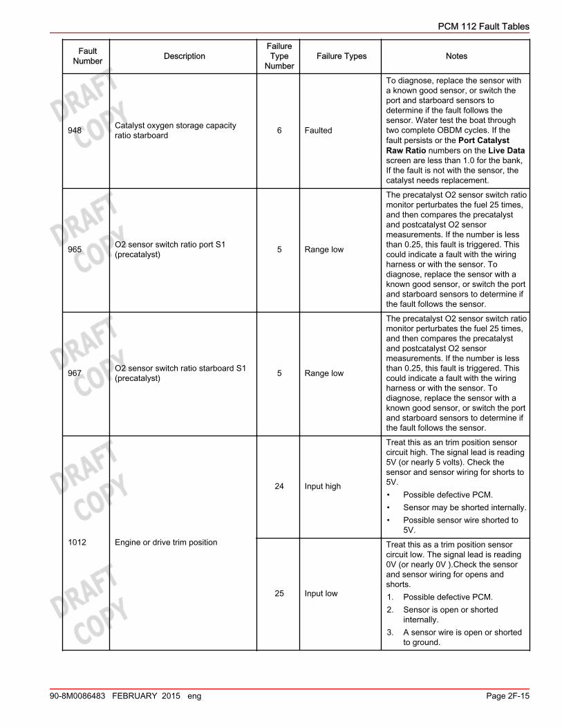
948 Catalyst oxygen storage capacityratio starboard 6 Faulted
To diagnose, replace the sensor witha known good sensor, or switch theport and starboard sensors todetermine if the fault follows thesensor. Water test the boat throughtwo complete OBDM cycles. If thefault persists or the Port CatalystRaw Ratio numbers on the Live Datascreen are less than 1.0 for the bank,If the fault is not with the sensor, thecatalyst needs replacement.
965 O2 sensor switch ratio port S1(precatalyst) 5 Range low
The precatalyst O2 sensor switch ratiomonitor perturbates the fuel 25 times,and then compares the precatalystand postcatalyst O2 sensormeasurements. If the number is lessthan 0.25, this fault is triggered. Thiscould indicate a fault with the wiringharness or with the sensor. Todiagnose, replace the sensor with aknown good sensor, or switch the portand starboard sensors to determine ifthe fault follows the sensor.
967 O2 sensor switch ratio starboard S1(precatalyst) 5 Range low
The precatalyst O2 sensor switch ratiomonitor perturbates the fuel 25 times,and then compares the precatalystand postcatalyst O2 sensormeasurements. If the number is lessthan 0.25, this fault is triggered. Thiscould indicate a fault with the wiringharness or with the sensor. Todiagnose, replace the sensor with aknown good sensor, or switch the portand starboard sensors to determine ifthe fault follows the sensor.
1012 Engine or drive trim position
24 Input high
Treat this as an trim position sensorcircuit high. The signal lead is reading5V (or nearly 5 volts). Check thesensor and sensor wiring for shorts to5V.• Possible defective PCM.• Sensor may be shorted internally.• Possible sensor wire shorted to
5V.
25 Input low
Treat this as a trim position sensorcircuit low. The signal lead is reading0V (or nearly 0V ).Check the sensorand sensor wiring for opens andshorts.1. Possible defective PCM.2. Sensor is open or shorted
internally.3. A sensor wire is open or shorted
to ground.
PCM 112 Fault Tables
90-8M0086483 FEBRUARY 2015 eng Page 2F-15

FaultNumber Description
FailureType
NumberFailure Types Notes
1021 Shift position
24 Input high
Treat this fault like a TPS circuit high.The ESC sensor signal is reading 5V(or nearly 5 volts). The sensor cannotbe replaced. You must replace theentire ESC.• Check the sensor leads for shorts
to 5V.• Possible defective PCM.• Sensor is shorted internally.• A sensor wire is shorted to 5V.
25 Input low
Treat this fault like a TPS circuit low.The ESC sensor signal is reading 0V(or nearly 0V ). The sensor cannot bereplaced. You must replace the entireESC.• Check the sensor leads for shorts
to ground.• Possible defective PCM.• Sensor is shorted internally.• A sensor wire is shorted to
ground.
1052 Crankshaft or camshaft trigger 6 Faulted
The camshaft sensor signal ismissing, erratic, or incorrectly phasedto the crankshaft sensor. Check thesensor leads for opens and shorts andloose or damaged connectors. Checkthe sensor for metal particles stickingto the sensor's magnet. Bump theengine over while monitoring thevoltage of the signal lead for 0 to 5Vchanges as the cam gear vanepasses the sensor.
1061 Mechanical demand sensor A24 Input high A sensor or sensor wire is shorted to
5V.
25 Input low A sensor or sensor wire is open orshorted to ground.
1062 Mechanical demand sensor B24 Input high A sensor or sensor wire is open or
shorted to ground.
25 Input low A sensor or sensor wire is shorted to5V.
1071 Mechanical demand sensor adapt A 6 FaultedThe demand sensor value is outsideof the adapt window of 125 ADC to275 ADC for 10 consecutive keyups.
1072 Mechanical demand sensor adapt B 6 FaultedThe demand sensor value is outsideof the adapt window of 125 ADC to275 ADC for 10 consecutive keyups.
1073 Mechanical demand sensors A and Bdifference 6 Faulted
If demand 1 reads X, then demand 2should read Y; one of them isincorrect.
1074 Mechanical demand sensors A and B 6 Faulted Both sensors are faulted. Possibleissue with transducer power.
1104 Drive lube 21 Too low Possible leak, stuck float switch, orwiring issue.
PCM 112 Fault Tables
Page 2F-16 90-8M0086483 FEBRUARY 2015 eng

FaultNumber Description
FailureType
NumberFailure Types Notes
1106 Neutral switch fault 6 Faulted ‑
1109 Emergency stop 23 Is activeThe wire is shorted to groundsomewhere between the engine andhelm.
2011 Guardian 23 Is active
This fault is a result of a separatefault. Any fault that indicates aproblem that could cause enginedamage will cause the Guardianprogram to activate. The more severethe problem, the more Guardian willreduce the available power.
2031 Guardian due to intake manifold airtemperature 23 Is active
Manifold air temp is over a calibratedlimit. Engine power is reduced toprevent engine damage.
2051 Guardian due to oil pressure 23 Is activeOil pressure is below a calibratedlimit. Engine power is being reducedto prevent engine damage.
2061 Guardian due to coolant pressure 23 Is activeSea pump pressure is below acalibrated limit. Engine power is beingreduced to prevent engine damage.
2081 Guardian due to overheat 23 Is active
Engine coolant temperature is abovea calibrated limit. Engine power isbeing reduced to prevent enginedamage.
2083 Time to closed loop fuel control 6 Faulted
The engine will not achieveclosed‑loop mode within the time limit.Cooling‑system problems may becausing the engine to take too long toreach operating temperature or neverreaching operating temperature.
2091 Guardian due to overspeed 23 Is active
The engine is exceeding the RPMlimit currently set by Guardian.Guardian power limits can range from90% down to forced idle(around 5%).This can be misleading as this is notthe maximum engine RPM limit; it justmeans the engine is going faster thanGuardian currently thinks it should.
2092 Neutral overspeed 23 Is active MerCruiser engines use a neutralRPM limit of 3500 RPM.
2101 Guardian due to power limit fromhelm module 23 Is active
Fix any command module faults tocorrect this fault. Refer to the DTSmanual.
2111 Guardian due to voltage 23 Is activeBattery voltage higher or lower thanallowable. Engine power is beingreduced to prevent engine damage.
PCM 112 Fault Tables
90-8M0086483 FEBRUARY 2015 eng Page 2F-17
FaultNumber Description
FailureType
NumberFailure Types Notes
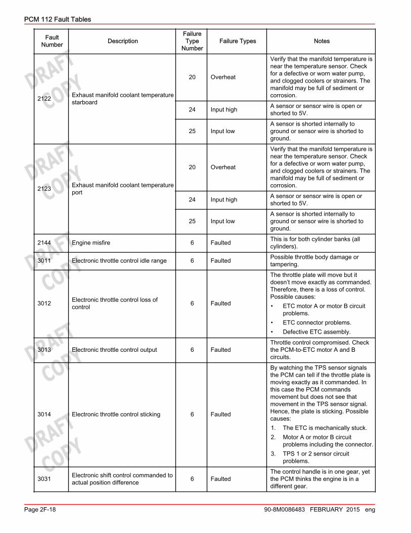
2122 Exhaust manifold coolant temperaturestarboard
20 Overheat
Verify that the manifold temperature isnear the temperature sensor. Checkfor a defective or worn water pump,and clogged coolers or strainers. Themanifold may be full of sediment orcorrosion.
24 Input high A sensor or sensor wire is open orshorted to 5V.
25 Input lowA sensor is shorted internally toground or sensor wire is shorted toground.
2123 Exhaust manifold coolant temperatureport
20 Overheat
Verify that the manifold temperature isnear the temperature sensor. Checkfor a defective or worn water pump,and clogged coolers or strainers. Themanifold may be full of sediment orcorrosion.
24 Input high A sensor or sensor wire is open orshorted to 5V.
25 Input lowA sensor is shorted internally toground or sensor wire is shorted toground.
2144 Engine misfire 6 Faulted This is for both cylinder banks (allcylinders).
3011 Electronic throttle control idle range 6 Faulted Possible throttle body damage ortampering.
3012 Electronic throttle control loss ofcontrol 6 Faulted
The throttle plate will move but itdoesn’t move exactly as commanded.Therefore, there is a loss of control.Possible causes:• ETC motor A or motor B circuit
problems.• ETC connector problems.• Defective ETC assembly.
3013 Electronic throttle control output 6 FaultedThrottle control compromised. Checkthe PCM‑to‑ETC motor A and Bcircuits.
3014 Electronic throttle control sticking 6 Faulted
By watching the TPS sensor signalsthe PCM can tell if the throttle plate ismoving exactly as it commanded. Inthis case the PCM commandsmovement but does not see thatmovement in the TPS sensor signal.Hence, the plate is sticking. Possiblecauses:1. The ETC is mechanically stuck.2. Motor A or motor B circuit
problems including the connector.3. TPS 1 or 2 sensor circuit
problems.
3031 Electronic shift control commanded toactual position difference 6 Faulted
The control handle is in one gear, yetthe PCM thinks the engine is in adifferent gear.
PCM 112 Fault Tables
Page 2F-18 90-8M0086483 FEBRUARY 2015 eng

FaultNumber Description
FailureType
NumberFailure Types Notes
3032 Electronic shift control loss of control 6 Faulted PCM is sending out commands for theESC to move but the
3036 Shift anticipation switch 6 Faulted
This fault is used on a mechanicalAlpha drive only. This fault is flaggedif the shift anticipate switch is activefor more than three seconds. Thisfault will shut down all sequences (fueland spark) and stop the engine.
3037 Electronic shift control timeout 6 Faulted Look for binding from the ESC downinto the gearcase.
3049 Shift output fault 16 Output fault Check the PCM‑to‑ESC motor A andB circuits.
3061 Fuel pump 16 Output fault Fuel pump relay or relay control circuit(relay pins 85 and 86) problem.
3151 Malfunction indicator lamp 16 Output fault Check PCM‑to‑lamp (on dash) circuit.
3152 Horn output fault 16 Output faultMechanical only. The horn isdisconnected or the circuit is openedor shorted.
3171 Starter 16 Output fault
The PCM has detected an open circuitor short circuit in the relay controlcircuit. This circuit uses pins 85 and86 in the relay. Battery voltage isalways present on one of these pins.The PCM will ground the otherthrough a yellow/black lead.• Check the yellow/black lead
between the PCM and the starterrelay for shorts and opens.
• Check the relay winding (pins 85and 86) for opens and shorts.
• Check for battery voltage to therelay control circuits.
• Refer to Section 3A.
3181 Trim up 16 Output faultA trim down relay or relay controlcircuit (relay pins 85 and 86) problem.Refer to Section 3A.
3182 Trim down 16 Output faultA trim down relay or relay controlcircuit (relay pins 85 and 86) problem.Refer to Section 3A.
4001 Demand crosscheck 6 FaultedCommand module and PCM are notmaking calculations correctly. Refer toDTS manual.
4002 Shift crosscheck 6 FaultedCommand module and PCM are notmaking calculations correctly. Refer toDTS manual.
4003 Helm module crosscheck 6 Faulted
The PCM sends a CAN message tothe command module asking it tomake a specific calculation. Theanswer is sent back to the PCM andcompared to the correct answer. Thisfault trips if the answer received isincorrect. Possible mismatchedsoftware or faulty command module.
PCM 112 Fault Tables
90-8M0086483 FEBRUARY 2015 eng Page 2F-19
FaultNumber Description
FailureType
NumberFailure Types Notes
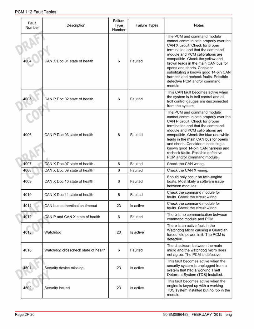
4004 CAN X Doc 01 state of health 6 Faulted
The PCM and command modulecannot communicate properly over theCAN X circuit. Check for propertermination and that the commandmodule and PCM calibrations arecompatible. Check the yellow andbrown leads in the main CAN bus foropens and shorts. Considersubstituting a known good 14‑pin CANharness and recheck faults. Possibledefective PCM and/or commandmodule.
4005 CAN P Doc 02 state of health 6 Faulted
This CAN fault becomes active whenthe system is in troll control and alltroll control gauges are disconnectedfrom the system.
4006 CAN P Doc 03 state of health 6 Faulted
The PCM and command modulecannot communicate properly over theCAN P circuit. Check for propertermination and that the commandmodule and PCM calibrations arecompatible. Check the blue and whiteleads in the main CAN bus for opensand shorts. Consider substituting aknown good 14‑pin CAN harness andrecheck faults. Possible defectivePCM and/or command module.
4007 CAN X Doc 07 state of health 6 Faulted Check the CAN wiring.
4008 CAN X Doc 09 state of health 6 Faulted Check the CAN X wiring.
4009 CAN X Doc 10 state of health 6 FaultedShould only occur on twin‑engineboats. Most likely a software issuebetween modules.
4010 CAN X Doc 11 state of health 6 Faulted Check the command module forfaults. Check the circuit wiring.
4011 CAN bus authentication timeout 23 Is active Check the command module forfaults. Check the circuit wiring.
4012 CAN P and CAN X state of health 6 Faulted There is no communication betweencommand module and PCM.
4013 Watchdog 23 Is active
There is an active fault in theWatchdog Micro causing a Guardianforced idle power limit. The PCM isdefective.
4016 Watchdog crosscheck state of health 6 FaultedThe checksum between the mainmicro and the watchdog micro doesnot agree. The PCM is defective.
4501 Security device missing 23 Is active
This fault becomes active when thesecurity system is unplugged from asystem that had a working TheftDeterrent System (TDS) installed.
4502 Security locked 23 Is active
This fault becomes active when theengine is keyed up with a workingTDS system installed but no fob in themodule.
PCM 112 Fault Tables
Page 2F-20 90-8M0086483 FEBRUARY 2015 eng
FaultNumber Description
FailureType
NumberFailure Types Notes
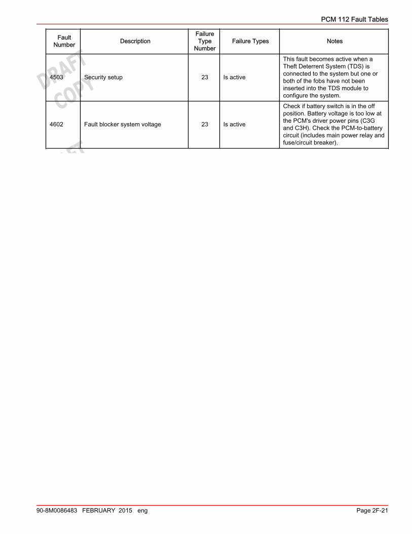
4503 Security setup 23 Is active
This fault becomes active when aTheft Deterrent System (TDS) isconnected to the system but one orboth of the fobs have not beeninserted into the TDS module toconfigure the system.
4602 Fault blocker system voltage 23 Is active
Check if battery switch is in the offposition. Battery voltage is too low atthe PCM's driver power pins (C3Gand C3H). Check the PCM‑to‑batterycircuit (includes main power relay andfuse/circuit breaker).
PCM 112 Fault Tables
90-8M0086483 FEBRUARY 2015 eng Page 2F-21

PCM 112 Fault Tables
Notes:
Page 2F-22 90-8M0086483 FEBRUARY 2015 eng