ce 4000 - parts express · fault monitoring ... in repeated stress tests, the ce 4000 continued to...
TRANSCRIPT

CE 4000
© 2001 by Crown Audio, Inc., P.O. Box 1000, Elkhart, IN 46515-1000 U.S.A.Telephone: 219-294-8000. Fax: 219-294-8329. Trademark Notice: Crown ® isa registered trademark of Crown International, Inc. Other trademarks are theproperty of their respective owners.
127393-2A3/01
Note: The information provided in this manual was deemed accurate as of thepublication date. However, updates to this information may have occurred. Toobtain the latest version of this manual, please visit the Crown website atwww.crownaudio.com.
Some models may be exported under the name Amcron.®
Obtaining Other Language Versions:To obtain information in another language about the use of this product, please contact yourlocal Crown Distributor. If you need assistance locating your local distributor, please contactCrown at 219-294-8200.

Page 3Page 2 Reference Manual Reference Manual
CE 4000 The amp with an Attitude!CE 4000 The amp with an Attitude!
ContentsDa Rules ...................................................................... 4Quick Start ................................................................... 61 Welcome ............................................................... 8
How To Use This Manual ..................................... 10Unpacking Your CE 4000 Amplifier ...................... 10Features .............................................................. 11Controls, Indicators & Connectors ....................... 12
2 Installation ........................................................... 143 Operation ............................................................ 244 Crown Pro Information Guides:
Balancing the Line .............................................. 29The Dastardly Duo: Hum and Buzz ..................... 30Guide to Neutrik Speakon NL4FC ConnectorAssembly ............................................................ 33
5 Advanced Features and Options:BCA .................................................................... 37Switching Power Supply with PFC ....................... 37Crown SST Modules ............................................ 38Fault Monitoring .................................................. 43Handle Kit ........................................................... 44Optional Output Connectors ................................ 44
6 Principles of Operation ........................................ 467 Specifications ..................................................... 528 Service ................................................................ 57
Important Safety Instructions1) Read these instructions.
2) Keep these instructions.
3) Heed all warnings.
4) Follow all instructions.
5) Do not use this apparatus near water.
6) Clean only with a dry cloth.
7) Do not block any ventilation openings. Install in accordancewith the manufacturer’s instructions.
8) Do not install near any heat sources such as radiators, heatregisters, stoves, or other apparatus that produce heat.
9) Do not defeat the safety purpose of the polarized or ground-ing-type plug. A polarized plug has two blades with onewider than the other. A grounding-type plug has two bladesand a third grounding prong. The wide blade or the thirdprong is provided for your safety. If the provided plug doesnot fit into your outlet, consult an electrician for replacementof the obsolete outlet.
10) Protect the power cord from being walked on or pinched,particularly at plugs, convenience receptacles, and the pointwhere they exit from the apparatus.
11) Only use attachments/accessories specified by the manu-facturer.
12) Use only with a cart, stand, bracket, or table specified by themanufacturer, or sold with the apparatus. When a cart isused, use caution when moving the cart/apparatus combina-tion to avoid injury from tip-over.
13) Unplug this apparatus during lightning storms or when un-used for long periods of time.
14) Refer all servicing to qualified service personnel. Servicing isrequired when the apparatus has been damaged in any way,such as power-supply cord or plug is damaged, liquid hasbeen spilled or objects have fallen into the apparatus, theapparatus has been exposed to rain or moisture, does notoperate normally, or has been dropped.
15) To reduce the risk of fire or electric shock, do not expose thisapparatus to rain or moisture.
Page 5Page 4 Reference Manual Reference Manual
CE 4000 The amp with an Attitude!CE 4000 The amp with an Attitude!
Da RulesDa Rules
����������� ������������������������������������
�����
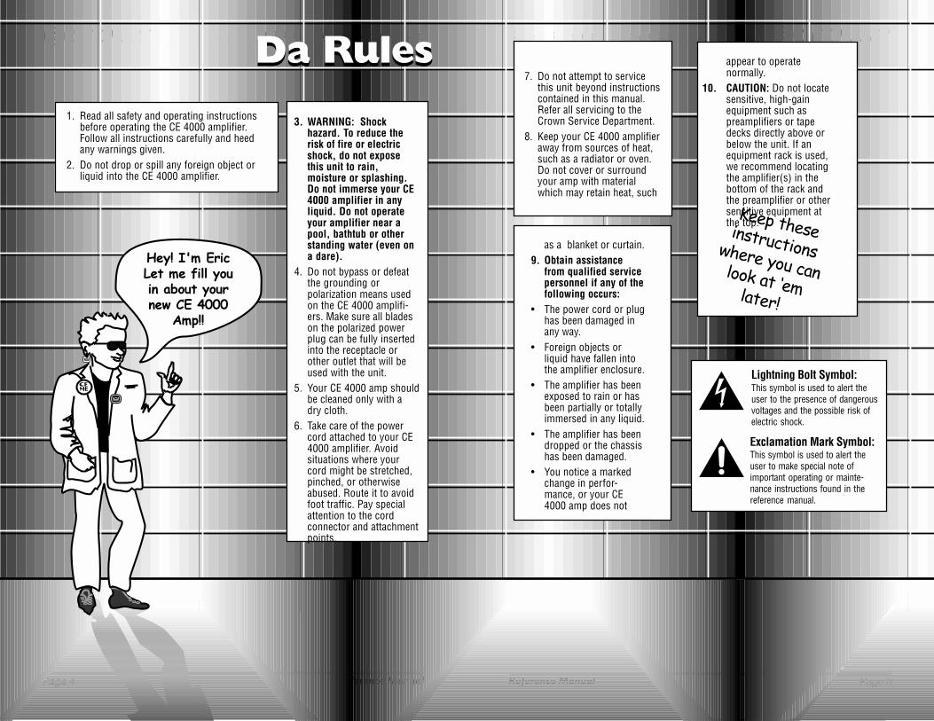
3. WARNING: Shockhazard. To reduce therisk of fire or electricshock, do not exposethis unit to rain,moisture or splashing.Do not immerse your CE4000 amplifier in anyliquid. Do not operateyour amplifier near apool, bathtub or otherstanding water (even ona dare).
4. Do not bypass or defeatthe grounding orpolarization means usedon the CE 4000 amplifi-ers. Make sure all bladeson the polarized powerplug can be fully insertedinto the receptacle orother outlet that will beused with the unit.
5. Your CE 4000 amp shouldbe cleaned only with adry cloth.
6. Take care of the powercord attached to your CE4000 amplifier. Avoidsituations where yourcord might be stretched,pinched, or otherwiseabused. Route it to avoidfoot traffic. Pay specialattention to the cordconnector and attachmentpoints.
7. Do not attempt to servicethis unit beyond instructionscontained in this manual.Refer all servicing to theCrown Service Department.
8. Keep your CE 4000 amplifieraway from sources of heat,such as a radiator or oven.Do not cover or surroundyour amp with materialwhich may retain heat, such
as a blanket or curtain.9. Obtain assistance
from qualified servicepersonnel if any of thefollowing occurs:
• The power cord or plughas been damaged inany way.
• Foreign objects orliquid have fallen intothe amplifier enclosure.
• The amplifier has beenexposed to rain or hasbeen partially or totallyimmersed in any liquid.
• The amplifier has beendropped or the chassishas been damaged.
• You notice a markedchange in perfor-mance, or your CE4000 amp does not
Lightning Bolt Symbol:This symbol is used to alert theuser to the presence of dangerousvoltages and the possible risk ofelectric shock.
Exclamation Mark Symbol:This symbol is used to alert theuser to make special note ofimportant operating or mainte-nance instructions found in thereference manual.
1. Read all safety and operating instructionsbefore operating the CE 4000 amplifier.Follow all instructions carefully and heedany warnings given.
2. Do not drop or spill any foreign object orliquid into the CE 4000 amplifier.
����������������� ������� ����� �������������
appear to operatenormally.
10. CAUTION: Do not locatesensitive, high-gainequipment such aspreamplifiers or tapedecks directly above orbelow the unit. If anequipment rack is used,we recommend locatingthe amplifier(s) in thebottom of the rack andthe preamplifier or othersensitive equipment atthe top.

Page 7Page 6 Reference Manual Reference Manual
CE 4000 The amp with an Attitude!CE 4000 The amp with an Attitude!
The Fault light blinks a few times, and the “Power” light willglow a bright green to indicate power is on.
8. (Now comes the fun!) Supply input, adjust amp levels andenjoy.
9. You can check the green signal light to verify input, if nec-essary.
CAUTION: Excessive output levels may toast your speak-ers. Crown’s CE 4000 amplifiers have such low distortion,you may not realize the actual level being reached untilit’s too late. Please exercise caution and drive your speak-ers responsibly (or at least warn your neighbors!).
Quick Start!You’ve waited a long time for this! We know you just can’t waitto crank up your new Crown® CE 4000 amplifier. And you suredon’t want to flip through pages of tech-talk just to find outwhere the on switch is. So that’s why we provided you with thisquick and simple page to get you up and running right away.Just take a few minutes to read through this—no more thanfive or ten, max—you’ll be glad you did.
1. Make sure the CE 4000 amp and all other equipment isturned off (“O”) before you begin wiring. By the way, theamp power switch is located on the far left side of the frontpanel. It is off (“O”) when depressed on the left.
2. Mount your CE 4000 amp securely in the rack, or positionit on a solid surface.
3. Connect the left and right inputs coming from your mixer,preamp, or processor. You can use either balanced 1/4-inch(6.35-mm) phone, 3-pin XLR or barrier block connectors. Youcan also choose to run in MONO mode. (See Figure2.5.)3.2.2 Output Wiring
WARNING: Output terminals marked with the symbolare dangerous when live. External wiring connected tothese terminals requires installation by an instructed per-son, or should make use of prebuilt wiring and connec-tors.
4. Connect the output wiring (left and right speakers). Youcan use your choice of Neutrik® Speakon® NL4FC, ba-nana, spade lug or bare wire, depending on the outputconnector configuration you have chosen.
5. Connect your CE 4000 amp and other equipment to yourpower source.
6. Turn on your mixer, preamp, signal processor, or anyother equipment in your system EXCEPT your CE 4000amplifier. (Remember: the best is worth waiting for.)
7. Make sure the Channel 1 and Channel 2 level (volume) con-trols on your CE 4000 amplifier are turned all the way down(counterclockwise), then flip the power switch on (“I”). Note:
Did You Remember To Get Your Speakons®?
Typical StereoHookup

Page 9Page 8 Reference Manual Reference Manual
CE 4000 The amp with an Attitude!CE 4000 The amp with an Attitude!
Fig. 1.1The CE 4000Amplifier
easily add a sub-bass system. Additional signal control is avail-able via Crown’s optional SST (System Solution Topologies)modules, which offer a wide variety of active crossover con-figurations.** Your choice of optional output connectors is alsoavailable: Neutrik Speakon® plus 5-way binding post, 5-waybinding post plus barrier strip, or dual Neutrik Speakon.
Weighing in at a mere 33.3 pounds, the CE 4000 is easy totransport and set up. What’s more, Crown’s enhanced, switch-mode power supply (featuring power factor correction) resultsin a universal power supply, so you can plug it in anywhere.And with the lowest cost per watt of any amp in its class, theCE 4000 is the obvious choice for serious musicians every-where.
Thanks for buying this CE 4000 amplifier. Here at Crown, weappreciate your support, and we think you’ll find that you’vealso done yourself a favor by choosing Crown. You see, CE4000 amplifiers have been engineered from the bottom up fortop-notch performance and unmatched reliability.
Designed using Crown’s patented, award-wining BCA® (Bal-anced Current Amplifier) engineering, the CE 4000 providessuperior power output, increased efficiency, legendary Crownsound and extraordinary reliability. With typical output powerat 3,600 watts*, the CE 4000 not only handles but excels athandling 2-ohm loads. In repeated stress tests, the CE 4000continued to perform at levels 12 dB into clip, long after thecompetition had shut down.
Designed for the utmost in flexibility, the CE 4000 features se-lectable on-board high- and low-pass filter sets, so you can
1 Welcome
** Your amplifier may have come already outfitted with a factory-installed SSTmodule, or your choice of SST modules can be added to an existing ampli-fier by an authorized Crown Service Center. For more information on fac-tory-installed SST modules, please refer to the Crown SST CrossoverReference Manual included in your literature package.
* 3,600 watts in Bridge-Mono mode at 4 ohms, 1,800 watts per channel at 2ohms. See the Specifications Section for details.

Page 11Page 10 Reference Manual Reference Manual
CE 4000 The amp with an Attitude!CE 4000 The amp with an Attitude!
FeaturesHow to Use This ManualThis manual will help you correctly install, set up and operateyour CE 4000 amplifier, including mounting, mode selection,standard input and output wiring, advanced features and op-tions setup, and typical operation. Please be sure to read allinstructions, warnings and cautions.
If your amplifier came equipped with an optional Crown SSTcrossover module, please refer to the SST Crossover Refer-ence Manual included in your literature package for informa-tion on amplifier setup.
For your protection, please send in the warranty registrationcard today. And save your bill of sale—it’s your official proofof purchase.
Unpacking Your CE 4000 AmpPlease unpack and inspect your amplifier for any damage thatmay have occurred during transit. If damage is found, notifythe transportation company immediately. Only you can initiatea claim for shipping damage. Crown will be happy to help asneeded. Save the shipping carton as evidence of damage forthe shipper’s inspection.
We also recommend that you save all packing materials soyou will have them if you ever need to transport the unit.NEVER SHIP THE UNIT WITHOUT THE FACTORY PACK.
* See Specification section for details.
Page 13Page 12 Reference Manual Reference Manual
CE 4000 The amp with an Attitude!CE 4000 The amp with an Attitude!
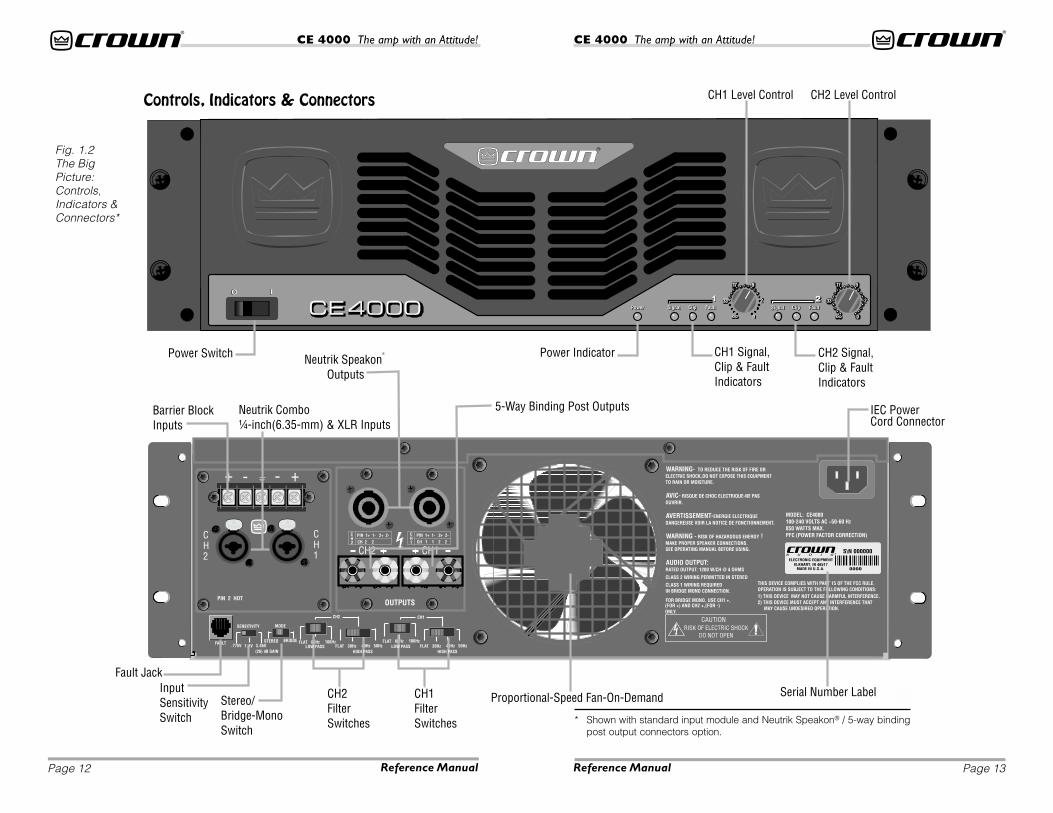
Fig. 1.2The BigPicture:Controls,Indicators &Connectors*
Controls, Indicators & Connectors
* Shown with standard input module and Neutrik Speakon® / 5-way bindingpost output connectors option.

Page 15Page 14 Reference Manual Reference Manual
CE 4000 The amp with an Attitude!CE 4000 The amp with an Attitude!
Fig. 2.1MountingDimensions
Fig. 2.2Mode Switch
2 InstallationFollow these instructions for a detailed explanation of CE 4000installation procedures and options. If you just want to get up andrunning as quickly as possible, see the Quick Start section onpage 6.
2.1—Begin with the amplifier turned off and disconnectedfrom the power receptacle. The CE4000 power switch islocated on the left side of the front panel; it is off (“O”) whendepressed on the left. Equipment that will be connected tothe inputs of the amplifier (such as mixers,equalizers or signalprocessors) should also be turned off.
2.2—Mount the amplifier. Your CE 4000 amp can be mounted ina standard, 19-inch (48.3-cm) equipment rack, or it can besimply stacked with other equipment. The CE 4000 amp isprovided with a convenient 3-foot (1-meter) power cord tominimize excess cordage when installed in a rack. Do notuse extension cords. Properly wired power outlets must beprovided close to the mounted amplifier.
If you choose to mount your amp in a rack, you should securethe back of the rack as well as the front. Securing the amp atboth front and rear will assure that the amp stays in place,even when the rack is transported or accidentally dropped(which we know never happens).
2.3—Set the mode switch. Make sure your amplifier is turnedoff (“O”) before moving this switch. The Mode switchshould be in the “Stereo” position when you’re running inStereo Mode. Stereo Mode allows independent inputs onthe left and right channels to feed separate speakers atthe output. It’s the configuration typically chosen for ev-eryday audio applications.
Turn the Mode switch to “Bridge-Mono” to have a singleinput that feeds to a single output with twice the voltageof Stereo Mode. Use this configuration if you want to give upstereo capabilities in order to drive your speakers louder.Note that the wiring will also need to be adjusted for thisconfiguration—that includes both input and output wir-ing. See Step 2.5 (Connecting the Outputs) and Figure 4.8later in this section for correct wiring when running inBridge-Mono mode.
2.4—Connect the inputs of the CE 4000 amp to your mixer,equalizers, or signal processors ahead of the amp. Threetypes of balanced input connectors are provided, allow-ing you to choose barrier strip,1/4-inch (6.35-mm) phoneor 3-pin XLR connectors.* You can also choose to use ei-ther balanced or unbalanced wiring. (See the informationon “Balancing the Line” in the Crown Pro InformationGuide section for an explanation of balanced vs. unbal-anced wiring.)
If the Mode switch is in “Bridge-Mono” position, onlythe Channel 1 input connectors should be used.
*Optional SST crossover may provide other input connector options.

Page 17Page 16 Reference Manual Reference Manual
CE 4000 The amp with an Attitude!CE 4000 The amp with an Attitude!
Input Wiring Tips1. For all input connectivity, use shielded wire only. Cables with a foilwrap shield or a high-density braid are superior. Cables with astranded spiral shield, although very flexible, will break down overtime and cause noise problems.
2. Try to avoid using unbalanced lines with professional equipment.If you have no choice, keep the cables as short as possible. (Refer to
the information on “Balancing the Line” in the Crown Pro Information Guide section.)
3. To minimize hum and crosstalk, avoid running low-level input, high-level output and ACpower feeds in the same path. Try to run differing signal paths at 90° to one another. If youmust use a common path for all cables, use a star-quad cable for the low-level signals.
4. When changing input connectors or wiring, turn the amplifier level controls all the waydown (counter-clockwise) before connecting or disconnecting input plugs.
5. When changing output connections, turn the amplifier level down and the AC power off tominimize the chance of short-circuiting the output. * Some optional output configurations may not offer Neutrik Speakon® con-
nectors.
Fig. 2.3Typical InputWiring
You will need two high-quality speaker cables terminatedwith the appropriate connectors to fit yourCE 4000 amp at one end and your speak-ers at the other end. Output Connector op-tions for the CE 4000 ampflifier includeNeutrik Speakon® plus 5-way bindingpost, 5-way binding post plus barrier strip,or dual Neutrik Speakon® outputs.
If you prefer, you can wire customspeaker cables to fit your exact requirements. For de-tailed instructions on wiring and assembling the Neutrik®
Speakon® NL4FC connectors, see the “Guide to NeutrikSpeakon NL4FC Connector Assembly” in the Crown ProInformation Guide section of this manual.
You may also choose to connect to the amplifier usingbanana, spade lugs, or bare wire connectors dependingon the output options specified for your amplifier.
IMPORTANT: Custom wiring should only be installedby qualified personnal.
Output Wiring Tips1. This amp offers Neutrik Speakon® connectors to minimize wiring
mistakes.* We also encourage you to choose carefully when select-ing speaker enclosure connectors.
2. To prevent possible short circuits, wrap or otherwise insulate ex-posed loudspeaker cable connectors.
3. Do not use connectors that might accidentally tie conductors to-gether when making or breaking the connection (for example, a standard, 1/4-inch(6.35-mm) stereo phone plug).
4. Never use connectors that could be plugged into AC power sockets. Accidental ACinput will be an electrifying experience for your equipment. But you will find out realquick if your speakers are any good at 60 Hz.
5. Avoid using connectors with low current-carrying capacity, such as XLRs.
6. Do not use connectors that have any tendency to short.
7. To maintain good bass response, use the lowest DC resistance cable you can af-ford which will terminate safely in your connectors.
WIRING SPEAKON®
OUTPUT CONNECTORS:
See the Crown Pro Informa-tion Guide section of thismanual.
2.5—Connect the outputs of the CE 4000 amp to your loud-speakers. For Stereo mode, refer to the Stereo OutputHookup diagram (Figure 2.4). For Bridge-Mono mode, re-fer to the Bridge-Mono Output Hookup diagram (Figure2.5).
WARNING: Output terminals marked with the symbolare dangerous when live. External wiring connected tothese terminals requires installation by an instructed per-son, or should make use of prebuilt wiring and connec-tors.
Page 19Page 18 Reference Manual Reference Manual
CE 4000 The amp with an Attitude!CE 4000 The amp with an Attitude!
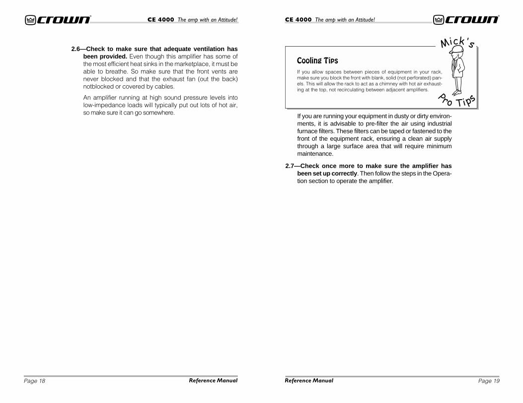
If you are running your equipment in dusty or dirty environ-ments, it is advisable to pre-filter the air using industrialfurnace filters. These filters can be taped or fastened to thefront of the equipment rack, ensuring a clean air supplythrough a large surface area that will require minimummaintenance.
2.7—Check once more to make sure the amplifier hasbeen set up correctly. Then follow the steps in the Opera-tion section to operate the amplifier.
2.6—Check to make sure that adequate ventilation hasbeen provided. Even though this amplifier has some ofthe most efficient heat sinks in the marketplace, it must beable to breathe. So make sure that the front vents arenever blocked and that the exhaust fan (out the back)notblocked or covered by cables.
An amplifier running at high sound pressure levels intolow-impedance loads will typically put out lots of hot air,so make sure it can go somewhere.
Cooling TipsIf you allow spaces between pieces of equipment in your rack,make sure you block the front with blank, solid (not perforated) pan-els. This will allow the rack to act as a chimney with hot air exhaust-ing at the top, not recirculating between adjacent amplifiers.

Page 21Page 20 Reference Manual Reference Manual
CE 4000 The amp with an Attitude!CE 4000 The amp with an Attitude!
Fig. 2.4Stereo Hookup—Two Stacks, OneAmp, Stereo In,Stereo Out

Page 23Page 22 Reference Manual Reference Manual
CE 4000 The amp with an Attitude!CE 4000 The amp with an Attitude!
Fig. 2.5DJ Application
Note: Mono hookup requires custom wiring on Neutrikconnectors. See Figure 4.8 for more information.

Page 25Page 24 Reference Manual Reference Manual
CE 4000 The amp with an Attitude!CE 4000 The amp with an Attitude!
3 OperationYour CE 4000 amp is really very easy to operate, once it hasbeen properly configured. If your amplifier has not yet beenset up or configured, please refer to the installation instruc-tions found in Section 2 of this manual, or consult with yoursystem installer.
Follow these steps when first turning on your amplifier:
1 Turn down the level of your audio source. For example,set your mixer’s volume to “¥” off.
2 Turn down the amplifier’s level controls (counter-clock-wise to “¥”).
3 Turn the power switch to the on (“I”) position. The powerindicator beside the switch will turn on.
4 After the Power light turns on, test the operating range ofyour input by turning up the level of your audio source tothe highest possible operating level before distortion. Youshould notice the green signal indicators glowing on youramplifier.
5 S-L-O-W-L-Y turn up the level controls on the front of theamplifier until the maximum desired loudness or powerlevel is achieved. Be prepared for astounding output!
6 Turn down the level of your audio source to its normalrange.
Controls & IndicatorsRefer to the following for information on how to operateand read your CE 4000 controls and indicators. See Fig-ures 3.1 and 3.2 for location of controls and indicators.
Power Switch: The power switch is conveniently located onthe front panel so you can easily turn the amplifier on (“I”) oroff (“O”). When the switch is depressed left, the amp is off.
Note that dangerous voltages may still be present in theamplifier even when the power switch is in the off (“O”)position. Before moving the amplifier or making any wiringor installation changes, it is important to also disconnectthe power cord from the amplifier or power source.
Figure 3.1 FrontPanel Indicators& Controls
Fault Indicators: Two red LEDs (one for each channel) arelocated on the front panel. The Fault Indicators are normallyOFF, but will blink under five different conditions:
1. When the amplifier is first powered up, until the unit isready for operation.
2. If the heatsinks reach a temperature above normal work-ing limits.

Page 27Page 26 Reference Manual Reference Manual
CE 4000 The amp with an Attitude!CE 4000 The amp with an Attitude!
3. If the transformer thermal protection circuit is activated.
4. If amplifier output wires develop a short-circuit.
5. Should the amplifier output stage become non-operational.
The fault status of the amplifier can also be monitored remotelyby attaching a signalling device to the Fault jack located onthe amplifier back-panel. See the Advanced Features andOptions section of this manual for more information on faultmonitoring and suggestions for signalling device circuity.
Some fault conditions may cause the output of the amplifier tobe muted.
Clip Indicator: Two red LEDs (one for each channel) are lo-cated on the front panel. The Clip indicators turn on when dis-tortion is audible in the amplifier output.
Signal Indicator: Two green LEDs (one for each channel) arelocated on the front panel. Unlike some of our other amplifiers,the Signal indicators on the CE 4000 amplifier lluminate whena signal (>–40 dBm) is present at the INPUT of the amplifier forthat channel. Because these indicators receive the signal be-fore the level controls, they can be used to troubleshoot wiringproblems within a system. If the Signal indicator for a channelis not lit, no signal is reaching the amplifier on that channel.
Power Indicator: A green LED is located on the front panel.The Power indicator lights when your CE 4000 amp has beenturned on and has power.
Level Controls: Two rotary level controls (one for each chan-nel) are located on the front panel. Use these controls to adjusteach channel’s output. To decrease the level, rotate the controlcounter-clockwise (to “¥”). To increase the level, rotate it clock-wise (to “0”).
Input Sensitivity Switch: A three-position Input Sensitivityswitch is located on the back panel near the input connectors.Your amplifier is shipped from the factory with this switch set tothe 1.4-V position. At this setting , a 1.4-V input signal will drivethe amplifier to full power into an 8-ohm load when the levelcontrols are turned to maximum. This translates to an amplifiergain of 33.8 dB or +4 dBu—a level at which most professionalequipment operates.
If required, the Input Sensitivity switch can be moved to the3.46-volt (26-dB) position, so that the amplifier provides a fixedvoltage gain of 20 (or 26 dB: 1 volt in, 20 volts out). This settingworks best with output levels of +10 dBu (2.5 volts RMS) ormore. Some brands of DJ mixers, in particular, have outputlevels in this range.
You can also choose the 0.775-volt setting for a gain of 39.0dB. This setting operates with a lower-level output and so maybe appropriate for use with consumer-grade CD players andsimilar items. Consult the owner’s manual of your input devicefor recommended sensitivity settings.
Selecting the correct sensitivity will allow your equipment tooperate at its optimum level and improve the signal-to-noise ofthe system.
Figure 3.2 BackPanel Controls

Page 29Page 28 Reference Manual Reference Manual
CE 4000 The amp with an Attitude!CE 4000 The amp with an Attitude!
On the other hand, an unbalanced circuit usually holds oneleg at ground potential, while the second leg is “hot.” Unbal-anced line is less expensive, but is much more susceptible tonoise, and is not usually used in professional applications. Forthe cleanest signal, without unwanted hum and buzz, bal-anced line is always recommended. It is especially helpful ifyou have a long cable run (over 10 feet (3 m)), since noise iseasily introduced into long, unbalanced lines.
–+
3
1
2
GND
FROMSOURCEINPUT
BALANCED
+–
SHIELD
FROMSOURCEINPUT
UNBALANCED
+
SHIELD
+3
1
2
SHIELD
4 Crown Pro Information GuidesBalancing the LineA balanced audio circuit typically will have both positive (+)and negative (–) legs of the circuit isolated from the groundcircuit. These balanced legs exhibit identical impedance char-acteristics with respect to ground, and may also carry the au-dio signal at the same level, but with opposite polarities. Thisresults in a line that offers excellent rejection of unwanted noise.
Fig. 4.1Balanced &UnbalancedInput Wiring
Fig. 4.2PolarityConversions
Mode Switch: This two-position switch, located on the backpanel, allows the selection of either Stereo or Bridge-Monomode of operation.
Stereo mode provides identical power output to each of thetwo amplifier output channels. Bridge-Mono Mode combinesthe two amplifier output channels into a single mono channelwith twice the voltage of a single stereo channel. This meansthe output will be much more powerful! It does this by bridgingthe outputs, and it requires special output wiring. Do NOT se-lect Bridge-Mono mode without first making sure the am-plifier has been wired in a Bridge-Mono configuration. Formore information on wiring for Bridge-Mono mode, see the In-stallation section of this manual, or consult your system in-staller.
When Bridge-Mono Mode is selected, only the Channel 1 Levelcontrol and the Channel 1 Signal LED will work. If the Channel2 input is wired, the Channel 2 Level control should be turnedto “¥”ÿ(counter/anti-clockwise) to prevent distortion.
CH1 and CH2 Filter Switches: A three-position low-passand a four-position high-pass filter switch for each channelare located on the back panel below the input and outputmodules. Low-pass filter is switchable among settings forFlat, 80 Hz and 100 Hz, with a 24-dB per octave rolloff. High-pass filter is switchable among settings for Flat, 30 Hz, 40Hz, and 50 Hz, with an 18-dB per octave rolloff.
Fault Jack: This RJ11 jack (which looks like a phone jack) islocated on the back panel. By attaching a signalling device tothe Fault jack, you can monitor the amplifier’s Fault status froma remote location. See the Advanced Features and Optionssection of this manual for more information on fault monitoringand suggestions for signalling device circuitry.
1/4 inch XLR(6.35 mm)
Tip = + = Pin 2
Ring = – = Pin 3
Sleeve = = Pin 1
Refer to Figure 4.2 for proper pin assignments for both ¼ inch(6.35-mm) and 3-pin XLR balanced audio wiring.

Page 31Page 30 Reference Manual Reference Manual
CE 4000 The amp with an Attitude!CE 4000 The amp with an Attitude!
Hum and Buzz Tips1. It is imperative that all of your electrical equipment share the same
power ground reference.
2. Unless you are interfacing to a microphone, the shield of the cableshould only be connected at one end. (See Fig.4.3)
3. Do not pass signal ground between electrical components in agrounded source system.
4. If you wish to avoid ground loops, it doesn’t matter if you lift the input or output signalground for your system topology, just be consistent. Personally I prefer to lift the inputsignal ground and it has always been successful...so far!
5. NEVER use a ground lift adapter to lift the power ground on a 3-wire AC cord; this is notits intended purpose. It is better to have it SAFE than SILENT!! Look for the true sourceof the noise.
6. Even when interfacing to an unbalanced load, it is preferable to use two-conductorshielded cable.
7. Get rid of the lighting company!
Fig. 4.3BalancedInput Wiring
The Dastardly Duo: Dr. Hum and Mr. BuzzIf you have noticeable hum or buzz in your system, you maywant to check your cable connections to see if the unwantednoise is being introduced via a ground loop. To determine theproper wiring, first check whether the output from your sourceis unbalanced or balanced (if you don’t know, refer to the unit’sback panel or instruction manual). If the source is balanced,refer to Figure 4.3; if it is unbalanced refer to Figure 4.4. Next,determine if the source’s power cable is floating (ungrounded,2-prong) or grounded (3-prong). Finally, if the source is unbal-anced, check the type of wiring: twin-lead or single coax.
Check Figure 4.4 to see if your cable has been wired with theproper shield and ground connection. If the cabling is incor-rect, you may be able to avoid the ground loop (and associ-ated hum) by plugging all of your equipment into the same ACcircuit (on the same breaker). If this is impractical, you will needto fix the cable to match the appropriate illustration. Or youmay want to simply replace the offending cable with a com-mercially manufactured cable of the appropriate type.

Page 33Page 32 Reference Manual Reference Manual
CE 4000 The amp with an Attitude!CE 4000 The amp with an Attitude!
Fig. 4.4UnbalancedInputWiring
To custom wire Neutrik Speakon NL4FC connectors, you willlneed the following materials: two (2) Neutrik Speakon® NL4FCconnectors* plus high-quality two- or four-conductor speakercable with the appropriate end-connectors to fit the inputs onyour speakers, a pair of needle-nosed pliers and a (1.5-mm) Allenwrench or a flat blade screw driver.
IMPORTANT: Custom wiring should only be installedby qualified personnal.
clearly not advantageous to the customer who wants to reconfigure his system orquickly change out a defective product. It is possible that similar regulatory con-trols will appear worldwide over the next few years.
One solution to this problem is to use the Neutrik® Speakon® connector. Here atCrown, we wanted to develop a system for you that eliminated the need for spe-cialized, time-consuming, interface cables. The major loudspeaker manufactur-ers have been using Speakon® connectors for the input termination on theirproducts for several years now, so you can be assured of the connector’s reliabil-ity in the workplace. With Speakon® connectors, you can plug straight from theamp to the speaker, and start making those great sounds right away.
The Speakon® connector meets all known safety regulations. Once wired cor-rectly, the connector cannot be plugged in backwards, causing the type of in-verted polarity situations that are common with banana hookups. It will provide asafe, secure and reliable method of interfacing your amplifier to the load.
Why Speakon?For amplifiers, the most popular termination device on profes-sional products has been the dual banana (which incidentallywas pioneered by Crown with the DC300 model). However, re-cent regulatory requirements in Europe have outlawed the useof the dual banana plug and forced users to terminate speakercables with spade lugs or bare ends—an approach that is
Guide to Neutrik® Speakon® NL4FC Connector Assembly
NOTE: You can purchase the Speakon® NL4FC connectors from yourlocal dealer, or contact NEUTRIK AG, Im alten riet 34, Schaan FL-9494,Furstentum Liechtenstein, 41-75-237-2424, FAX 41-75-232-5393,www.neutrik.com or Neutrik USA, Inc., 195 Lehigh Ave., Lakewood, NJ08701-4527, 908-901-9488, FAX 908-901-9608, www.neutrikusa.com orCrown Audio, Inc., 1718 West Mishawaka Road, Elkhart, IN 46517-4095,USA, 219-294-8000, FAX 219-294-8329, www.crownaudio.com.

Page 35Page 34 Reference Manual Reference Manual
CE 4000 The amp with an Attitude!CE 4000 The amp with an Attitude!
To assemble the Neutrik Speakon NL4FC connector,complete the following steps:
1. Slide the bushing (E) and chuck (D) onto the end of thecable as shown in Figure 4.5.*
* Your NL4FC connector kit should contain both a black and a white chuck.Use the white chuck for cable with a diameter of 0.25 to 0.5 inch (6.35 to12.7 mm). Use the black chuck for cable with a diameter of 0.375 to 0.625inch (9.525 to 15.875 mm).
Fig.4.5Order ofAssembly fortheNeutrik®
Speakon®NL4FCConnector
Fig.4.5Wiring for theNeutrik®
Speakon®
NL4FCConnector
2. Strip approximately 3/4-inch (20-mm) of casing from the cableend. Strip approximately 3/8-inch (8-mm) from the end of eachof the conductors down to bare wire (C).
3a. Insert each wire into the top of appropriate slot of the con-nector insert (B) as shown in Figure 4.6. Use a (1.5-mm)Allen wrench or flat blade screwdriver to tighten the sideconnecting screws.
3b. If the Mode switch is in the “Stereo” position (for stereoconfiguration), connect the positive (+) and negative (–)leads of each wire to the appropriate Channel 1 andChannel 2 connectors as shown in Figure 4.7. You mayuse all 4 poles of the Channel 1 output connector to feedboth speakers, if you wish.
Fig.4.7Stereo OutputWiring
Fig.4.8Bridge-MonoOutput Wiring
Fig. 4.9ConnectorAssembly: Insertinto Connector
3c. If the Mode switch is in the “Bridge” position (for monoconfiguration), connect the load across the positive (+)terminals of the connector as shown in Figure 4.8. ForBridge-Mono Mode, non-inverting output, Ch1+ is thepositive (+) and Ch2+ is the negative (–).
3d. Never short or parallel the output channels of an amplifier to itself or any other amplifier.
4. Slide the connector insert (B) into the connector housing(A), making sure that the large notch on the outer edge ofthe insert lines up with the large groove on the inside of theconnector housing. The insert should slide easily throughthe housing and out the other side until it extends approxi-mately 3/4-inch (19-mm) from the end of the housing. (See Fig-ure 4.9.)

Page 37Page 36 Reference Manual Reference Manual
CE 4000 The amp with an Attitude!CE 4000 The amp with an Attitude!
5 Advanced Features & OptionsBCA®
BCA® (Balanced Current Amplifier) is Crown’s patented, cut-ting-edge technology that gets more power out of an amplifierwith less waste than was ever before possible. A completelynew adaptation of standard amplifier design, Crown’s BCA“switching” amplifier design provides for high output, excep-tional reliability and nearly twice the efficiency of typical ampli-fier designs.
While switching designs have been used successfully in otherapplications, these designs were never before suitable for usein precision, high-power audio amplifier applications. Crown’sBCA technology changes that, with a totally new paradigm foramplifier design that represents the future of professional am-plifiers.
With their superior efficiency, BCA amplifiers can help to keepyour power bills down, while still putting out amazing, bass-thumping lows and crystal clear highs. And your Crown BCAamp is tough—easily handling very low (and highly reactive)load impedances, even under extreme conditions. In fact,Crown BCA amps have far out-performed competitive amplifi-ers in tests where the amplifier was run as much as 12-dB intoclip for extended periods of time.
High efficiency, tough robust design and great Crown soundmake Crown BCA amplifiers the clear choice for professionalmusicians everywhere.
Switching Power Supply with PFCCrown’s new Switching Power Supply with PFC provides arange of benefits over both non-switching and conventionalswitching power-supply designs.
5. Slide the chuck (D) along the cable and insert into thehousing, making sure that the large notch on the outeredge of the chuck lines up with the large groove on theinside of the connector housing. The chuck should slideeasily into the insert/housing combination until only approxi-mately 3/8-inch (9.5-mm) of the chuck end extends from theback end of the connector as shown in Figure 4.10.
Fig.4.10ConnectorAssembly: Chuckinto ConnectorHousing
Fig.4.11ConnectorAssembly: Bushingonto ConnectorHousing Assembly
6. Slide the bushing along the cable and screw onto the endof the connector combination as shown in Figure 4.11.Note that the bushing features a special locking con-struction which will prevent disassembly of theNL4FC connector once this cap is tightened intoplace. Before tightening, you may want to test the con-nector in a live system to make sure it has been as-sembled properly.

Page 39Page 38 Reference Manual Reference Manual
CE 4000 The amp with an Attitude!CE 4000 The amp with an Attitude!
For information on wiring and configuration of amplifiersequipped with an optional Crown SST crossover module,please refer to the SST Crossover Reference Manual includedin your literature package.
Refer to the following descriptions for an overview of availableCrown SST crossover modules.
SST-MX CrossoverThe SST-MX crossover module features 24-dB/octave Linkwitz-Riley tuned filters and stereo sub-bass outputs for biamp op-eration of subs. See Figure 5.1 for SST-MX block diagram.
Features of the SST-MX crossover include:• Stereo biamp.
• 100-Hz fixed crossover
• 24-dB/octave Linkwitz-Riley tuned filters.
Typical non-switching power supplies require large, heavytransformers in order to produce the required power at the out-put stage. These transformers must be large to absorb thesubstantial waste that occurs when operating at 50 to 60 Hz(standard AC supplied by the power company).
By contrast, switching power supplies can operate with a muchsmaller (and lighter) transformer because they first convert theAC up to a much higher frequency, thereby reducing waste.
However, in both non-switching and conventional switchingdesigns, phase differences occur within the power supply dueto the inductance of the transformer. This phase difference pre-vents much of the available power from the AC mains frommaking its way to the load.
PFC, however, compensates for phase differences in thepower supply, allowing more true power to be transferred tothe amplifier. The result is more power with less waste than anyother conventional switching or non-switching design.
As an added benefit, PFC also allows the amp to be connectedto any common AC line voltage, without converting the powersupply. This means that whether you’re running one or twoamps on a household circuit or several amps on a power distro,your CE 4000 amplifiier is ready—right out of the box.
Crown SST ModulesCrown’s optional SST (System Solution Topologies) moduleswere specially designed to improve the fidelity and versatilityof your audio system. They feature a variety of professionalsignal routing and filtering capabilities, with active crossoversthat allow the audio signal to be split and sent to auxiliary am-plifiers. Your amplifier may have come with an SST modulealready factory-installed, or your choice of SST modules canbe easily added to the amplifier by any authorized Crown Ser-vice Center.
Why Biamped?When you use one of Crown’s SST crossover modules to split the powerdrive to your loudspeaker components, you gain a wide range of advan-tages, including:
1. Increased gain because the insertion loss of passive crossover net-works is eliminated.
2. Consistent power bandwidth: power bandwidth is changed in multi-way passive systems if transducers change impedance or vaporize(blow up).
3. Levels can be matched more accurately to the components.
4. Quicker troubleshooting.
5. Improved dynamic range.
6. Better protection of components due to steep 24-dB/octave filters.

Page 41Page 40 Reference Manual Reference Manual
CE 4000 The amp with an Attitude!CE 4000 The amp with an Attitude!
Fig. 5.1SST-MXCrossoverBlock Diagram
CH
1
CH
1S
UB
OU
T
TB
CH
2S
UB
OU
T
100
Hz
LP
CH
2
–– ++
IN
BY
PA
SS
100
Hz
HP
HO
ST
AM
PLIF
IER
CH
1IN
PU
T
HO
ST
AM
PLIF
IER
CH
2IN
PU
T
100
Hz
LP
24
dB
/oct.
slo
pe
100
Hz
HP
24
dB
/oct.
slo
pe
IN
BY
PA
SS
100
Hz
LP
24
dB
/oct.
slo
pe
100
Hz
HP
24
dB
/oct.
slo
pe
–+ – +
– +
3
2
1
– +
3
2
1
Fig. 5.2SST-SXCrossoverBlock Diagram
• Neutrik® Combo ¼-inch (6.35-mm) and XLR input jacks.
• Barrier block balanced outputs.
• Optional high-pass filter bypass on amplified outputsadapts system for full-range use.
SST-SX CrossoverThe SST-SX crossover module features 24-dB/octave Linkwitz-Riley tuned filters and mono-summed sub-bass outputs forbiamp operation of subs. See Figure 5.2 for SST-SX block dia-gram.
Features of the SST-SX crossover include:• Mono-summed sub-bass output.
• 24-dB/octave Linkwitz-Riley tuned filters.
• Crossover switchable between 80 and 120 Hz.
• Neutrik® Combo ¼-inch (6.35-mm) and XLR input jacks.
• Male 3-pin XLR outputs
• Optional high-pass filter bypass on amplified outputadapts system for full-range use.

Page 43Page 42 Reference Manual Reference Manual
CE 4000 The amp with an Attitude!CE 4000 The amp with an Attitude!
Figure 5.3Block Diagramfor Crown’sSST-SBSC
SST-SBSC (Summed Bass Stereo Crossover) ModuleCrown’s advanced SST-SBSC module offers ten user-speci-fied crossover frequencies, CD horn EQ and summed sub-bass output for driving subs (see Figure 5.3 for block diagram).The SST-SBSC offers the following features:
• Stereo biamp.
• 12-, 18- and 24-dB (Linkwitz-Riley) / octave filters.
• CD horn equalization.
• Mono summing of sub-bass output for driving subs.
Crown plans to release additional accessory plug-in modulesoffering a range of advanced features and capabilities. Watchfor new releases.
Fault MonitoringThe Fault (RJ11) jack, which looks like a telephone plug, islocated on the back of your CE 4000 amplifier. It gives you aneasy way to remotely monitor the amplifier’s fault status. To setup a circuit that will cause an LED to light whenever a faultstatus occurs, you can simply use the suggested circuit shownin Figure 5.4.
When using this circuit, the LED will glow whenever the ampli-fier is in one of four states: a channel’s heatsink has reached itstemperature limit, the transformer has reached its temperaturelimit, the amplifier has just been turned on and is in its turn-on-delay mode, or the amplifier is turned off.

Page 45Page 44 Reference Manual Reference Manual
CE 4000 The amp with an Attitude!CE 4000 The amp with an Attitude!
Fig. 5.5RJ Jack Wiringand PinAssignments
Fig. 5.6Model CE4EDual NeutrikSpeakon®
OutputConnectors
Fig. 5.7Model CE4C5-way BindingPost plusBarrier StripOutputConnectors
* The mating connector for the CE 4000’s RJ11 jack contains 4 contact pinsin a 6-slot case, as shown. For additional information please contact yourlocal dealer or Crown Technical Support.
Fig. 5.4Fault Status LED Circuitry
If you choose to design your own circuit to interface this signalto your system, note that this RJ jack is polarity sensitive. Pin 2must be grounded, and Pin 5 must be supplied with a positivevoltage pull up (positive with respect to ground). Refer to Fig-ure 5.5 for RJ jack pin assignments.* The maximum signal thatcan be exposed to the fault jack is 35 VDC and 10 mA. Bestresults are obtained with 10 mA LEDs.
Handle KitHandles complement your amplifier’s appearance, aid in trans-portation, and the placement in or removal from racks. Theyare available from Crown’s Sales Department.
Optional Output ConnectorsFor added system flexibility, Crown offers optional output con-nector configurations for your CE 4000 amplifier. If you prefer,you can choose to have dual Neutrik Speakon® output con-nectors (model CE4E) or 5-way binding post plus barrier strip
(model CE4C) connectors installed in your amplifier in placeof the standard Neutrik Speakon® plus 5-way binding post out-puts (model CE4D) at time of ordering. See Figures 5.6 and5.7. For information on adding optional output connector mod-ules to an existing CE 4000 amplifier, please contact CrownTechnical Support.

Page 47Page 46 Reference Manual Reference Manual
CE 4000 The amp with an Attitude!CE 4000 The amp with an Attitude!
Principles of OperationAudio Signal PathFor the sake of simplicity, only channel one of the audio signalpath is described.
Signal is presented to the CE 4000 through one of three con-nectors when using the standard input module. Each channelis outfitted with a balanced XLR / phone jack, and a barrierstrip. These connectors are wired in parallel, which allowsdaisy chaining when needed. The signal is then convertedfrom balanced to unbalanced in the Balanced Input Stagewhere it also receives RFI protection. Signal then flows into theVariable Gain Stage where the front panel level controls areallowed to affect the gain.
Following this stage, the signal goes through a gain stage thatallows for the various positions of the sensitivity switch. Thesignal is then put under the control of a full-time compressorcircuit comprised of a symmetrical window detector, a bufferamplifier, and the gating op amp which uses several smallcomponents to set the compressor’s attack and decay char-acteristics. The actual compressing is accomplished by anopto-isolator that affects the gain in the signal path.
The signal then is passed through a series of switchable filtersthat allow the signal to be low-pass and high-pass filtered atvarious frequencies. The switches are located at the backpanel. The low-pass filter is a fourth-order Linkwitz-Riley type(24-dB/octave rolloff) and the high-pass filter is a third-orderButterworth type (18-dB/octave rolloff).
Following the switchable filters, the signal enters a 32 kHz 7th
Order Gaussian Low-Pass Filter. This filter prevents the modu-lator stage and the output filter (both described below) fromreceiving signals that are too high. Without the 32 kHz filter,the modulator would be unable to process signals that are toohigh and the output filter would not yield the proper frequencyresponse behavior. The Gaussian filter type is unique in that ithas minimal ringing and excellent phase response so even ahigh-order filter such as this one does not adversely affect thesonic excellence of the product.
The signal next enters the main amplifier error amp where it ismixed with a small portion of the output voltage and current insuch a way as to control the amplifier’s overall output perfor-
mance. Warning: Details of closed loop amplifier design arebeyond the scope of this description and if discussed, wouldsurely put most readers to sleep!
Following the error amp is the modulator stage where the au-dio signal is compared to an extremely accurate 250 kHz tri-angle waveform. Comparators output a Pulse Width Modulated(PWM) string of pulses at 250 kHz that vary in width depend-ing on the level of the input signal. These strings of pulses, onefor the positive side and one for the negative side, are con-nected to the output stage via optocouplers.
The signals from the optos are then passed to gate drivers thatamplify the pulses to the level required to drive output devices.The driven ou
tput devices are now able to produce PWM pulses that havean output voltage from the negative high-voltage rail (-Vcc) tothe positive high-voltage rail (+Vcc). This output voltage isalways the same (2 * Vcc) but the width of the pulses is stilldependent on the level of the input signal. The positive andnegative output PWM pulses then pass through inductors andare summed together. Summing the output signals throughinductors reconstructs the audio signal, amplified to the de-sired level. There is a small amount of ripple on the output thatis at double the switching frequency (500 kHz).
The amplified audio signal is then passed through an outputfilter that removes the residual ripple voltage. The power isdelivered to the load cables through the output connectorpanel which consists of one of several options.
Protection for the output devices is performed by a very pre-cise pulse-by-pulse current limiter circuit that operates eachtime the output devices switch. The current limiting is “flat”meaning that, regardless of the output voltage, the output cur-rent always limits at a certain value.
The turn-on delay circuitry functions to keep the modulatorsturned off (which keeps the outputs from switching) until allsupplies are up and stable.
Thermal probes monitor Heatsink temperatures and powertransformer temperature. As the temperatures rise, the probessend a proportional voltage to the fan control circuit and theThermal Limit Control (TLC) circuit. The fan normally runs atvery low speed when the amplifier is idling or when it is being
Page 49Page 48 Reference Manual Reference Manual
CE 4000 The amp with an Attitude!CE 4000 The amp with an Attitude!
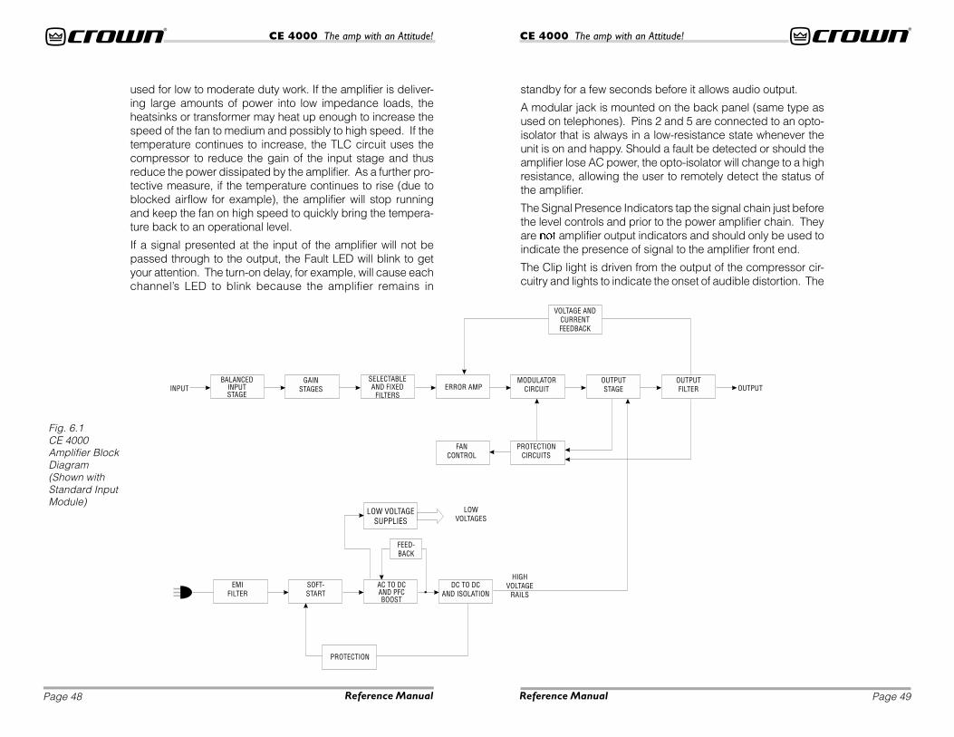
Fig. 6.1CE 4000Amplifier BlockDiagram(Shown withStandard InputModule)
used for low to moderate duty work. If the amplifier is deliver-ing large amounts of power into low impedance loads, theheatsinks or transformer may heat up enough to increase thespeed of the fan to medium and possibly to high speed. If thetemperature continues to increase, the TLC circuit uses thecompressor to reduce the gain of the input stage and thusreduce the power dissipated by the amplifier. As a further pro-tective measure, if the temperature continues to rise (due toblocked airflow for example), the amplifier will stop runningand keep the fan on high speed to quickly bring the tempera-ture back to an operational level.
If a signal presented at the input of the amplifier will not bepassed through to the output, the Fault LED will blink to getyour attention. The turn-on delay, for example, will cause eachchannel’s LED to blink because the amplifier remains in
standby for a few seconds before it allows audio output.
A modular jack is mounted on the back panel (same type asused on telephones). Pins 2 and 5 are connected to an opto-isolator that is always in a low-resistance state whenever theunit is on and happy. Should a fault be detected or should theamplifier lose AC power, the opto-isolator will change to a highresistance, allowing the user to remotely detect the status ofthe amplifier.
The Signal Presence Indicators tap the signal chain just beforethe level controls and prior to the power amplifier chain. Theyare not amplifier output indicators and should only be used toindicate the presence of signal to the amplifier front end.
The Clip light is driven from the output of the compressor cir-cuitry and lights to indicate the onset of audible distortion. The
Page 51Page 50 Reference Manual Reference Manual
CE 4000 The amp with an Attitude!CE 4000 The amp with an Attitude!
Power LED is driven from the low-voltage supply.
Power Supply OperationAC power enters the amplifier through a power cord equippedwith an IEC (unplugable) connector. It then is passed throughthe EMI filter. Circuits that use switching technology will nor-mally send a small amount of high-frequency noise back downthe power cord and into the power distribution system. Thisnoise must be removed in order to sell the unit in certain partsof the world. Since the CE4000 is a worldwide product, theEMI filter removes this noise so that it does not exit the box.
The power then enters the Power Factor Correction (PFC)Boost stage. This stage is what allows the CE4000 to beplugged into any outlet in the world without any modificationsto the amplifier. The PFC stage uses switching power supplytechnology to take whatever AC line voltage comes in, convertit to DC and boost it to 400 Volts. The circuit also uses intelli-gence to draw the current from the line sinusoidally and inphase with the line voltage. This reduces the load on the powercompanies and also allows the amplifier to pull more peakpower from the power source (the outlet). The power is drawnin small amounts 62,500 times each second and is used toprovide power to the isolation stage and to fill the large energyreservoir capacitors.
The power then goes to the “buck” isolation stage. This stage
takes the 400 Volt PFC voltage and, again using switchingpower supply technology, converts it down (“bucks” it down)to the level needed to power the audio output stage. The iso-lation stage also satisfies a safety requirement by providingisolation, using a transformer, between the AC mains powerand the power that is delivered to your speakers. The isolationstage moves power 125,000 times each second from the pri-mary to the secondary to power the audio output stage andkeep its large energy reservoir capacitors full.
In order to keep the power supply controllers, protection cir-cuits, and the audio signal path components powered, anotherswitching power supply is used, this one also running at 125kHz. This one is also a “buck” type supply in that it takes volt-age from the 400 Volt PFC bus and converts it down to the lowvoltages needed. This circuit also uses a transformer to pro-vide safety isolation.
Like the audio signal path parts of the amplifier, there are manyways that the power supply protects itself. Part of the start-uptime delay mentioned above occurs while the power supply isramping up all of its voltages (soft-start) so that large inrushcurrents are avoided. Current limiters and over-current detec-tors are used to protect the power supply output devices. Thepower supply will also detect severe brownouts and shut offthe supply until the brown-out is over if the line voltage is dras-tically less than normal.

Page 53Page 52 Reference Manual Reference Manual
CE 4000 The amp with an Attitude!CE 4000 The amp with an Attitude!
7 SpecificationsNote: All measurements are in Stereo mode with 8-ohm loads and aninput sensitivity of 26-dB gain at 1-kHz rated power unless otherwisespecified.
PowerOutput Power: (see Figure 7.1).
Load Impedance: Safe with all types of loads. Rated for 2, 4and 8 ohms in Stereo mode, 4 and 8 ohms in Bridge-Monomode.
Voltage Gain to 1-kHz, 8-ohm rated output:39.0-dB gain at 0.775-volt sensitivity;33.8-dB gain at 1.4-volt sensitivity;26-dB gain at 3.46-volt sensitivity.
Required AC Mains: 50/60 Hz , 100-240VAC (±10%).
AC Line Current,100 Volts: 8.5 A;120 Volts: 7.1 A;230-240 Volts: 3.7 A;At Idle: Amp draws no more than 140 watts.
AC Line Connector: 15A IEC Connector with CountrySpecific Cord and Plug.
PerformanceFrequency Response: ±0.25 dB from 20 Hz to 20 kHz at 1watt (See Figure 7.2).
Phase Response: ±15 degrees deviation from linear phasefrom 20 Hz to 20 kHz at 1 watt.
Signal to Noise Ratio,A-Weighted, 20 Hz to 20 kHz:
Better than 102 dB below rated 1-kHz power;
Total Harmonic Distortion (THD): 1-kHz rated power, 0.5% orless THD from 20 Hz to 20 kHz.
Intermodulation Distortion (IMD): (60 Hz and 7 kHz at 4:1)Less than 0.5% at rated power to 30 dB below rated power at8 ohms.
Damping Factor: Greater than 1000 from 10 Hz to 400 Hz.*
Crosstalk: Better than 50 dB below rated power, 20 Hz to 20kHz.
Common Mode Rejection (CMR): Better than 70 dB from 20Hz to 1 kHz.
DC Output Offset (Shorted Input): ±10 mV.
Controls & ConnectorsLevel: A detented rotary level control for each channel locatedon the front panel.
Power: An on/off rocker switch located on the front panel.
Mode: Turn power off before switching. A two-position switch lo-cated on the back panel below the input connectors which, whenturned to stereo, operates the amplifier as two independent chan-nels. When “Bridge-Mono” mode is selected, the amplifier bridgesthe two output channels for twice the output voltage.
Sensitivity: A three-position switch located on the back panelnext to the Mode switch. Switchable among 0.775 volts or 1.4volts for full output into an 8-ohm load (default setting), or 3.46volts for a fixed voltage gain of 26 dB.
Fault Jack: A back-panel RJ11 jack that may be remotely moni-tored to signal amplifier Fault condition. An LED or other signallingdevice (not supplied) may be used.
Filter Switches:Low Pass: A three-position switch for each channellocated on the back panel below the input and outputmodules. Switchable among settings for Flat, 80 Hz and100 Hz. Filter rolloff is 24-dB per octave.High Pass: A four-position switch for each channellocated on the back panel below the input and outputmodules. Switchable among settings for Flat, 30 Hz, 40 Hzand 50 Hz. Filter rolloff is 18-dB per octave.
IndicatorsSignal: A green LED for each channel which flashes when avery low-level signal (>–40 dBm) is present at input. May beused for troubleshooting cable runs.
* Measured using binding-post output connectors.

Page 55Page 54 Reference Manual Reference Manual
CE 4000 The amp with an Attitude!CE 4000 The amp with an Attitude!
Clip: A red LED for each channel which turns on when distor-tion becomes audible in the amplifier output.
Fault: Normally off, this red indicator will blink under five differ-ent conditions:
1. When the amplifier is first powered up, until the unit isready for operation.
2. If the heatsinks reach a temperature above normal work-ing limits.
3. If the transformer thermal protection circuit is activated.
4. If amplifier output wires develop a short-circuit.
5. Should the amplifier output stage become non-opera-tional.
This circuit may be monitored remotely by plugging a simpleswitching circuit using an LED or other signaling device intothe back-panel RJ11 (Fault) jack. Under some conditions, theoutput of the amplifier will be muted.
Power: A green LED that turns on when the amplifier hasbeen turned on and has power.
Input/OutputInput Connector (standard module): One Neutrik® Comboconnector for each channel which features a balanced ¼-inch(6.35-mm) phone jack and a 3-pin female XLR connector, inparallel with a barrier strip termination.
Input Stage: Input is electronically balanced and employs pre-cision 1% resistors.
Input Impedance: Nominally 20 k ohms, balanced. Nominally10 k ohms, unbalanced.
Input Sensitivity: 0.775 volts or 1.4 volts for standard 1-kHzpower, or fixed 26-dB gain.
Output Connectors: Three options available: Four (4) Neutrik®
Speakon® NL4MP (mates with NL4FC) output connectors; (2)5-way binding posts in parallel with two (2) Speakon® connec-tors; or barrier strip outputs in parallel with two (2) 5-way bind-ing posts.
Output Signal,Stereo:
Unbalanced, two-channel;
Bridge-Mono:Balanced, single-channel. Channel 1 controls areactive; Channel 2 should be turned down.
Wiring Configuration: (see Figure: 7.3).
ProtectionCE 4000 amplifiers are protected against shorted, open or mis-matched loads; overloaded power supplies; excessive tem-perature, chain destruction phenomena, input overloaddamage and high-frequency blowups. They also protect loud-speakers from input/output DC, large or dangerous DC offsetsand turn-on/turn-off transients.
ConstructionRugged steel chassis is formed into a durable package anystagehand could love. Coated with environmentally friendlypowder for long life and ease of maintenance.
Cooling: Proportional-speed fan-on-demand.
Dimensions: EIA Standard 19-inch rack mount width (EIA RS-310-B), 5.25-inch (13.34-cm) height and 16.25-inch (36.56-cm) depth with additional 1-inch rear rack ears.
Weight: The CE 4000 net weight is 33.3 pounds (15.1 kg).Shipping weight is 39.3 pounds.

Page 57Page 56 Reference Manual Reference Manual
CE 4000 The amp with an Attitude!CE 4000 The amp with an Attitude!
8 ServiceYour amplifier should only be serviced by a fully trained techni-cian at an authorized service center.
CAUTION: To prevent electric shock, do not remove cov-ers. No user serviceable parts inside. Refer servicing to aqualified technician.
Worldwide ServiceService may be obtained from an authorized service center.(Contact your local Crown/Amcron representative or our officefor a list of authorized service centers.) To obtain service, sim-ply present the bill of sale as proof of purchase along with thedefective unit to an authorized service center. They will handlethe necessary paperwork and repair.
Remember to transport your unit in the original factory pack-ing!
North American ServiceService may be obtained in one of two ways: from an autho-rized service center or from the factory. You may choose either.It is important that you have your copy of the bill of sale as yourproof of purchase.
Service at a North American Service CenterThis method usually saves the most time and effort. Simplypresent your bill of sale along with the defective unit to an au-thorized service center to obtain service. They will handle thenecessary paperwork and repair. Remember to transport theunit in the original factory packing. A list of authorized servicecenters in your area can be obtained from our Technical Sup-port Group.
Factory ServiceTo obtain factory service, fill out the service information pagefound in the back of this manual and send it along with yourproof of purchase and the defective unit to the Crown factory.
For warranty service, we will pay for ground shipping both waysin the United States. Contact Crown Factory Service or Techni-cal Support to obtain prepaid shipping labels prior to sendingthe unit. Or, if you prefer, you may prepay the cost of shipping,and Crown will reimburse you.
Fig. 7.2AwesomeFrequency(Amplitude)Response
Fig. 7.3Output PinAssignmentsWhen UsingSpeakonConnectorsOption
Fig.7.1CE4000Output Power
1800W*1200W600W
3600W*
2400W
2 ohm Dual
8 ohm Bridge-Mono
4 ohm Bridge-Mono
8 ohm Dual
4 ohm Dual
CE 4000 Power ChartMaximum power @ 1 kHzwith 0.5% THD
*

Page 59Page 58 Reference Manual Reference Manual
CE 4000 The amp with an Attitude!CE 4000 The amp with an Attitude!
Send copies of the shipping receipts to Crown to receive reim-bursement.
Your repaired unit will be returned via UPS ground. Please con-tact us if other arrangements are required.
Factory Service Shipping Instructions:
1 When sending a Crown product to the factory for service,be sure to fill out the service information form found in theback of this manual and enclose it inside your unit’s ship-ping pack. Do not send the service information formseparately.
2 To ensure the safe transportation of your unit to the fac-tory, ship it in an original factory packing container. If youdon’t have one, call or write Crown’s Parts Department.Do not use loose, small size packing materials.
3 Do not ship the unit in any kind of cabinet or rack (wood ormetal). Ignoring this warning may result in extensive dam-age to the unit and the cabinet. Accessories are notneeded—do not send cables and other hardware. Do notsend this instruction manual, if we forget what we said, wehave duplicates!
If you have any questions, please call or write the Crown Tech-nical Support Group.
Always use theoriginal factory
packing totransportthe unit.
Crown Customer ServiceTechnical Support / Factory ServicePlant 2 SW, 1718 W. Mishawaka Rd., Elkhart,Indiana 46517 U.S.A.
Telephone: 219-294-8200800-342-6939 (North America, Puerto Rico, and Virgin Islands only)
Facsimile: 219-294-8301 (Technical Support)219-294-8124 (Factory Service)
Internet: http://www.crownaudio.com

WORLDWIDESUMMARY OF WARRANTY
The Crown Audio Division of Crown International, Inc., 1718 West Mishawaka Road,Elkhart, Indiana 46517-4095 U.S.A. warrants to you, the ORIGINAL PURCHASER andANY SUBSEQUENT OWNER of each NEW Crown1 product, for a period of three (3)years from the date of purchase by the original purchaser (the “warranty period”) thatthe new Crown product is free of defects in materials and workmanship, and we furtherwarrant the new Crown product regardless of the reason for failure, except asexcluded in this Crown Warranty.1 Note: If your unit bears the name “Amcron,” please substitute it for the name “Crown”in this warranty.
ITEMS EXCLUDED FROM THIS CROWN WARRANTYThis Crown Warranty is in effect only for failure of a new Crown product which occurredwithin the Warranty Period. It does not cover any product which has been damagedbecause of any intentional misuse, accident, negligence, or loss which is coveredunder any of your insurance contracts. This Crown Warranty also does not extend tothe new Crown product if the serial number has been defaced, altered, or removed.
WHAT THE WARRANTOR WILL DOWe will remedy any defect, regardless of the reason for failure (except as excluded),by repair, replacement, or refund. We may not elect refund unless you agree, or unlesswe are unable to provide replacement, and repair is not practical or cannot be timelymade. If a refund is elected, then you must make the defective or malfunctioningproduct available to us free and clear of all liens or other encumbrances. The refundwill be equal to the actual purchase price, not including interest, insurance, closingcosts, and other finance charges less a reasonable depreciation on the product fromthe date of original purchase. Warranty work can only be performed at our authorizedservice centers. We will remedy the defect and ship the product from the servicecenter within a reasonable time after receipt of the defective product at our authorizedservice center.
HOW TO OBTAIN WARRANTY SERVICEYou must notify us of your need for warranty service not later than ninety (90) days afterexpiration of the warranty period. All components must be shipped in a factory pack.Corrective action will be taken within a reasonable time of the date of receipt of thedefective product by our authorized service center. If the repairs made by ourauthorized service center are not satisfactory, notify our authorized service centerimmediately.
DISCLAIMER OF CONSEQUENTIAL & INCIDENTAL DAMAGESYOU ARE NOT ENTITLED TO RECOVER FROM US ANY INCIDENTAL DAMAGESRESULTING FROM ANY DEFECT IN THE NEW CROWN PRODUCT. THIS INCLUDESANY DAMAGE TO ANOTHER PRODUCT OR PRODUCTS RESULTING FROM SUCHA DEFECT.
WARRANTY ALTERATIONSNo person has the authority to enlarge, amend, or modify this Crown Warranty. ThisCrown Warranty is not extended by the length of time which you are deprived of theuse of the new Crown product. Repairs and replacement parts provided under theterms of this Crown Warranty shall carry only the unexpired portion of this CrownWarranty.
DESIGN CHANGESWe reserve the right to change the design of any product from time to time withoutnotice and with no obligation to make corresponding changes in products previouslymanufactured.
LEGAL REMEDIES OF PURCHASERNo action to enforce this Crown Warranty shall be commenced later than ninety (90)days after expiration of the warranty period.
THIS STATEMENT OF WARRANTY SUPERSEDES ANY OTHERSCONTAINED IN THIS MANUAL FOR CROWN PRODUCTS.
9/90
TH
RE
E Y
EA
RFU
LL W
AR
RA
NT
YYEAR3
Telephone: 219-294-8200. Facsimile: 219-294-8301
NORTH AMERICASUMMARY OF WARRANTY
The Crown Audio Division of Crown International, Inc., 1718 West Mishawaka Road,Elkhart, Indiana 46517-4095 U.S.A. warrants to you, the ORIGINAL PURCHASER andANY SUBSEQUENT OWNER of each NEW Crown product, for a period of three (3)years from the date of purchase by the original purchaser (the “warranty period”) thatthe new Crown product is free of defects in materials and workmanship. We furtherwarrant the new Crown product regardless of the reason for failure, except asexcluded in this Warranty.
ITEMS EXCLUDED FROM THIS CROWN WARRANTYThis Crown Warranty is in effect only for failure of a new Crown product which occurredwithin the Warranty Period. It does not cover any product which has been damagedbecause of any intentional misuse, accident, negligence, or loss which is coveredunder any of your insurance contracts. This Crown Warranty also does not extend tothe new Crown product if the serial number has been defaced, altered, or removed.
WHAT THE WARRANTOR WILL DOWe will remedy any defect, regardless of the reason for failure (except as excluded),by repair, replacement, or refund. We may not elect refund unless you agree, or unlesswe are unable to provide replacement, and repair is not practical or cannot be timelymade. If a refund is elected, then you must make the defective or malfunctioningproduct available to us free and clear of all liens or other encumbrances. The refundwill be equal to the actual purchase price, not including interest, insurance, closingcosts, and other finance charges less a reasonable depreciation on the product fromthe date of original purchase. Warranty work can only be performed at our authorizedservice centers or at the factory. We will remedy the defect and ship the product fromthe service center or our factory within a reasonable time after receipt of the defectiveproduct at our authorized service center or our factory. All expenses in remedying thedefect, including surface shipping costs in the United States, will be borne by us. (Youmust bear the expense of shipping the product between any foreign country and theport of entry in the United States and all taxes, duties, and other customs fees for suchforeign shipments.)
HOW TO OBTAIN WARRANTY SERVICEYou must notify us of your need for warranty service not later than ninety (90) days afterexpiration of the warranty period. All components must be shipped in a factory pack,which, if needed, may be obtained from us free of charge. Corrective action will betaken within a reasonable time of the date of receipt of the defective product by us orour authorized service center. If the repairs made by us or our authorized servicecenter are not satisfactory, notify us or our authorized service center immediately.
DISCLAIMER OF CONSEQUENTIAL & INCIDENTAL DAMAGESYOU ARE NOT ENTITLED TO RECOVER FROM US ANY INCIDENTAL DAMAGESRESULTING FROM ANY DEFECT IN THE NEW CROWN PRODUCT. THIS INCLUDESANY DAMAGE TO ANOTHER PRODUCT OR PRODUCTS RESULTING FROM SUCHA DEFECT. SOME STATES DO NOT ALLOW THE EXCLUSION OR LIMITATIONS OFINCIDENTAL OR CONSEQUENTIAL DAMAGES, SO THE ABOVE LIMITATION OR
EXCLUSION MAY NOT APPLY TO YOU.
WARRANTY ALTERATIONSNo person has the authority to enlarge, amend, or modify this Crown Warranty. ThisCrown Warranty is not extended by the length of time which you are deprived of theuse of the new Crown product. Repairs and replacement parts provided under theterms of this Crown Warranty shall carry only the unexpired portion of this CrownWarranty.
DESIGN CHANGESWe reserve the right to change the design of any product from time to time withoutnotice and with no obligation to make corresponding changes in products previouslymanufactured.
LEGAL REMEDIES OF PURCHASERTHIS CROWN WARRANTY GIVES YOU SPECIFIC LEGAL RIGHTS, YOU MAY ALSOHAVE OTHER RIGHTS WHICH VARY FROM STATE TO STATE. No action to enforce thisCrown Warranty shall be commenced later than ninety (90) days after expiration of thewarranty period.
THIS STATEMENT OF WARRANTY SUPERSEDES ANY OTHERSCONTAINED IN THIS MANUAL FOR CROWN PRODUCTS.
9/90
YEAR3
TH
RE
E Y
EA
RFU
LL W
AR
RA
NT
Y
Telephone: 219-294-8200. Facsimile: 219-294-8301

Crown Factory Service InformationShipping Address: Crown Audio, Inc., Factory Service,
Plant 2 SW, 1718 W. Mishawaka Rd., Elkhart, IN U.S.A. 46517Phone: 1-800-342-6939 or 1-219-294-8200 Fax: 1-219-294-8124
Owner’s Name: __________________________________________________________Shipping Address: ______________________________________________________Phone Number: _______________________ Fax Number: ___________________Model: _______________________________ Serial Number: _________________
Purchase Date: __________________________________________________________
NATURE OF PROBLEM(Be sure to describe the conditions that existed when the
problem occurred and what attempts were made to correct it.)
_______________________________________________________________________
_______________________________________________________________________
_______________________________________________________________________
_______________________________________________________________________
_______________________________________________________________________
Other equipment in your system: __________________________________________
_______________________________________________________________________
_______________________________________________________________________
_______________________________________________________________________
_______________________________________________________________________
If warranty has expired, payment will be:o Cash/Check o VISA o MasterCard o C.O.D.
Card Number:___________________________
Exp. Date: __________ Signature:____________________________
ENCLOSE THIS PORTION WITH THE UNIT.DO NOT MAIL SEPARATELY.