ce5107 lecture 3 print version
TRANSCRIPT

1
Lecture 3Settlement of Single Pile and
Pile Group
Associate Professor C F LeungDepartment of Civil Engineering, NUSEmail : [email protected]
Kaohsiung Taiwan Aug 2004
Building settles excessively but rather uniformly due to water drawdown caused by nearby subway construction.1st storey now becomes the basement!!

2
Differential settlement is often a major concern. Pisa Tower is the famous case.
Tilt of building under construction in Singapore, Jan 2003
Tilt angle 0.1o
Top of building displaces 0.3048 m
Thus settlement can be the governing factor in pile design!
3
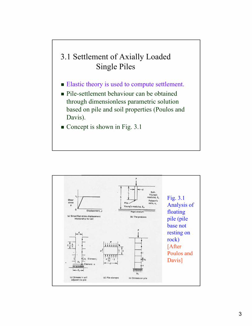
3.1 Settlement of Axially Loaded Single Piles
Elastic theory is used to compute settlement.Pile-settlement behaviour can be obtained through dimensionless parametric solution based on pile and soil properties (Poulos and Davis).Concept is shown in Fig. 3.1
Fig. 3.1 Analysis of floating pile (pile base not resting on rock) [After Poulos and Davis]

4
Elastic Theory
Pile is divided into a number of elements (Fig. 3.1(e))The vertical displacement (sρ) of the soil adjacent to the pile at element i resulting from a stress Pj on an element j is given by
sρij = (d/Es) Iij Pj
where d = pile diameterEs = Young’s modulus of soilIij = vertical displacement factor for element i due
to shear stress at element j=
ρI =
After Mindlin (1936) [Refer to Poulos and Davis Appendix A]z1, z, R1, and R2 are some physical distance between
element i and element j ∴The soil displacement at element i due to P of all the
elements and the base is sρi =
where db = diameter of pile basePb = stress at pile base

5
The displacement of the pile elements is taken care ofby the pile stiffness factor, K = Ep RA/Eswhere Ep = Young modulus of pile material
RA = pile area ratio = Ap/(πd2/4)= 1 for pile with solid cross-section.
By means of finite difference method and by ensuringthat the stress and displacement are compatible for allthe elements, solutions for stress and displacementalong the pile are obtained.
[The most relevant one is the displacement (settlement)at the pile top]
3.2 Floating Piles
Piles with base not resting on rock (hard stratum) i.e. Young’s modulus of soil at pile base Eb = Es.Pile head settlement
ρ = P I / (Es d)where P = applied axial load on pile
I = influence factor= I0 Rk Rh Rv (Figs. 3.2 to 3.5)
d = pile shaft diameterand Es = Young’s modulus of soil
6
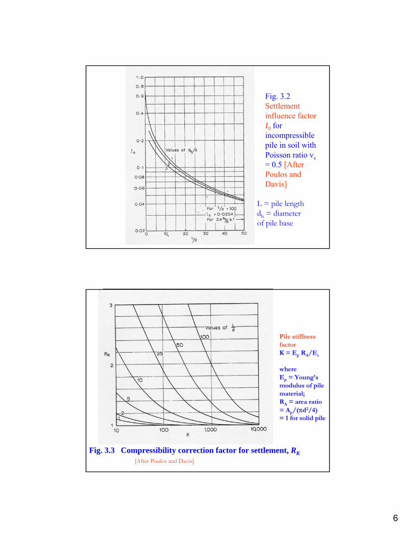
Fig. 3.2 Settlement influence factor I0 for incompressible pile in soil with Poisson ratio νs= 0.5 [After Poulos and Davis]
L = pile lengthdb = diameter of pile base
Fig. 3.3 Compressibility correction factor for settlement, RK
Pile stiffness factorK = Ep RA/Es
whereEp = Young’s modulus of pile material;RA = area ratio = Ap/(πd2/4) = 1 for solid pile
[After Poulos and Davis]

7
Fig. 3.4 Depth correction factor for settlement Rh
h is the thickness of soil to hard rock (rigid stratum)
[After Poulos and Davis]
Fig. 3.5 Poisson’s ratio correction factor for settlement, Rν
[After Poulos and Davis]

8
3.3 End Bearing Piles
Pile with base resting on hard rock end bearing stratum, i.e. Eb > Es.Refer to Fig. 3.6 for the analysis of end bearing pile.Pile head settlement
ρ = P I / (Es d)where I = I0 Rk Rb Rv,
and Rb = correction factor for stiffness of bearing stratum (Fig. 3.7)
Fig. 3.6 Analysis of end-bearing pile
Mirror image is assumed at the hard bearing stratum
[After Poulos and Davis]
9
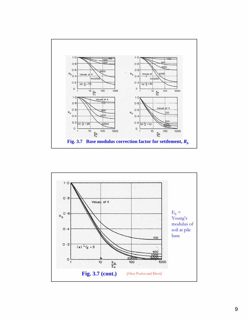
Fig. 3.7 Base modulus correction factor for settlement, Rb
Fig. 3.7 (cont.)
Eb = Young’s modulus of soil at pile base
[After Poulos and Davis]
10
3.4 Non-Homogeneous Soil
If modulus variation between successive layers along pile length L is not large, use average soil modulus
Eav = [Σ(Ei hi)]/L
where Ei = modulus of soil layer i,hi = thickness of soil layer i.
For a pile penetrates one soil layer and founded in the second distinctly different soil layer:
(1) Treat the portion of pile in 1st layer as end bearing pile, determine settlement, sρ1 of this portion subjected to applied load P
(2) Determine the load transfer at the interface of the 2 soil layers P2.
(3) Calculate settlement in 2nd layer, sρ2 subjected to P2.(4) Sum up sρ1 and sρ2 to obtain overall settlement of
pile head.
11
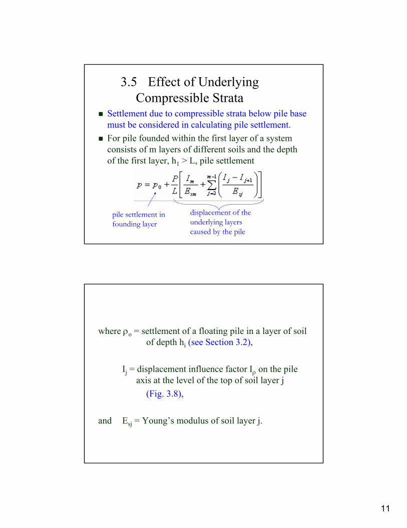
3.5 Effect of Underlying Compressible Strata
Settlement due to compressible strata below pile base must be considered in calculating pile settlement.For pile founded within the first layer of a system consists of m layers of different soils and the depth of the first layer, h1 > L, pile settlement
pile settlement in founding layer
displacement of the underlying layers caused by the pile
where ρo = settlement of a floating pile in a layer of soil of depth hi (see Section 3.2),
Ij = displacement influence factor Iρ on the pile axis at the level of the top of soil layer j
(Fig. 3.8),
and Esj = Young’s modulus of soil layer j.
12
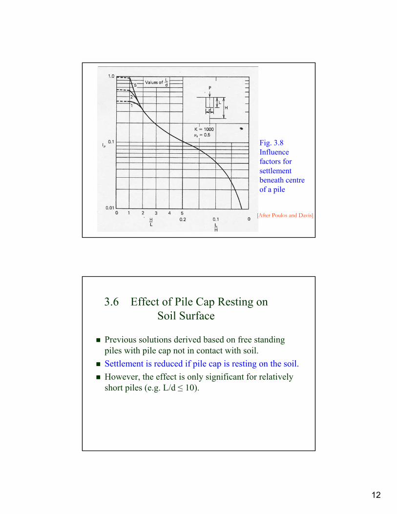
Fig. 3.8 Influence factors for settlement beneath centre of a pile
[After Poulos and Davis]
3.6 Effect of Pile Cap Resting on Soil Surface
Previous solutions derived based on free standing piles with pile cap not in contact with soil.Settlement is reduced if pile cap is resting on the soil. However, the effect is only significant for relatively short piles (e.g. L/d ≤ 10).

13
3.7 Soil Parameters(1) Clay
Backfigured drained Young’s modulus E’s for pile in clay, refer to Fig. 3.9.Drained Poisson’s ratio v’s as follow:Stiff OC clays 0.1 to 0.2 (ave 0.15)Medium stiff clay 0.2 to 0.35 (ave 0.3)Soft NC clays 0.35 – 0.45 (ave 0.4)Undrained soil parameters (for immediate settlement calculation only, therefore not so useful) Eu = 1.5 E’s/(1+ v’s ), and vu = 0.5 for saturated clay
Fig. 3.9 Backfigured soil modulus E’s for piles in clay (after Poulos and Davis)
Note differences in Es values (including upper limit of Es) for driven and bored piles
14
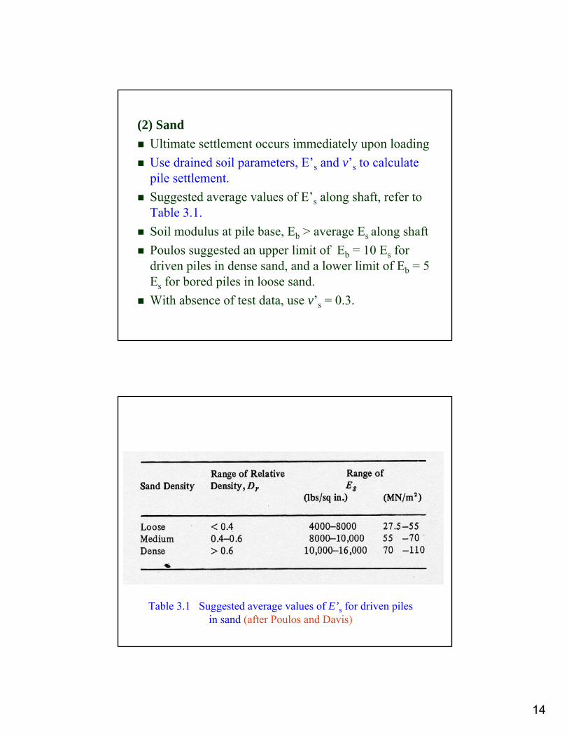
(2) SandUltimate settlement occurs immediately upon loadingUse drained soil parameters, E’s and v’s to calculate pile settlement.Suggested average values of E’s along shaft, refer to Table 3.1.Soil modulus at pile base, Eb > average Es along shaftPoulos suggested an upper limit of Eb = 10 Es for driven piles in dense sand, and a lower limit of Eb = 5 Es for bored piles in loose sand.With absence of test data, use v’s = 0.3.
Table 3.1 Suggested average values of E’s for driven piles in sand (after Poulos and Davis)

15
3.8 Settlement of Axially Loaded Pile Groups
Simplified equivalent raft approach- Soil is treated as continuum and presence of piles is
ignored.- Load is transferred to a depth where soil is stronger
and less compressible (Fig. 3.10)- Total pile group settlement = settlement of virtual
foundation placed at some depth below ground surface.
- Final settlement = (immediate settlement + consolidation settlement) of the virtual foundation.
Fig 3.10 Settlement of Pile Groups (Equivalent raft concept)

16
Fig 3.10 cont. (After US Navy Design Manual DM7)
3.9 Interaction Factor Approach
Consider two identical equally loaded piles (Fig. 3.11) in an elastic mass to obtain relationship between centre-to-centre spacing between piles, s and interaction factor, α.
α = ratio of additional settlement caused by adjacent pile to settlement of pile under its own load.
17
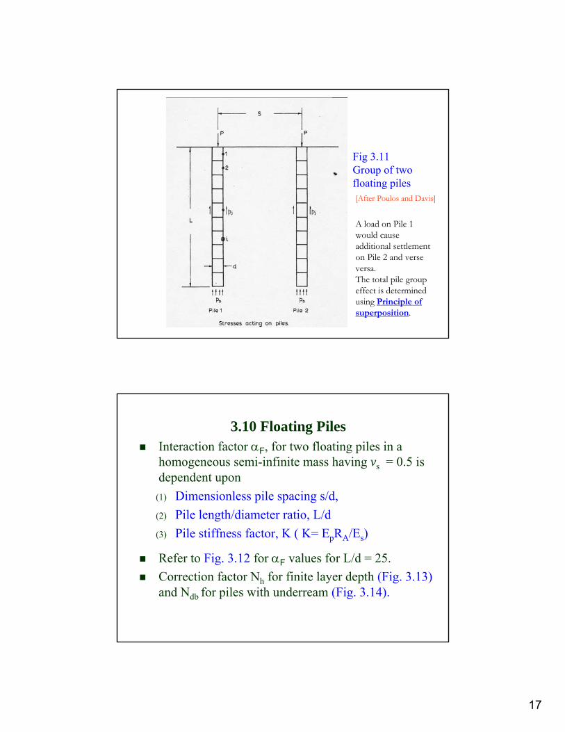
Fig 3.11 Group of two floating piles[After Poulos and Davis]
A load on Pile 1 would cause additional settlement on Pile 2 and verse versa.The total pile group effect is determined using Principle of superposition.
3.10 Floating PilesInteraction factor αF, for two floating piles in a homogeneous semi-infinite mass having vs = 0.5 is dependent upon
(1) Dimensionless pile spacing s/d,(2) Pile length/diameter ratio, L/d(3) Pile stiffness factor, K ( K= EpRA/Es)
Refer to Fig. 3.12 for αF values for L/d = 25.Correction factor Nh for finite layer depth (Fig. 3.13)and Ndb for piles with underream (Fig. 3.14).

18
Fig 3.12 Interaction factors αF for floating piles, L/d = 25Refer to Poulos and Davis on charts for other L/d values
[After Poulos and Davis]
Fig 3.13 Correction factors Nh to interaction factors, for effect of finite layer depth (L/d = 25)
[After Poulos and Davis]
19
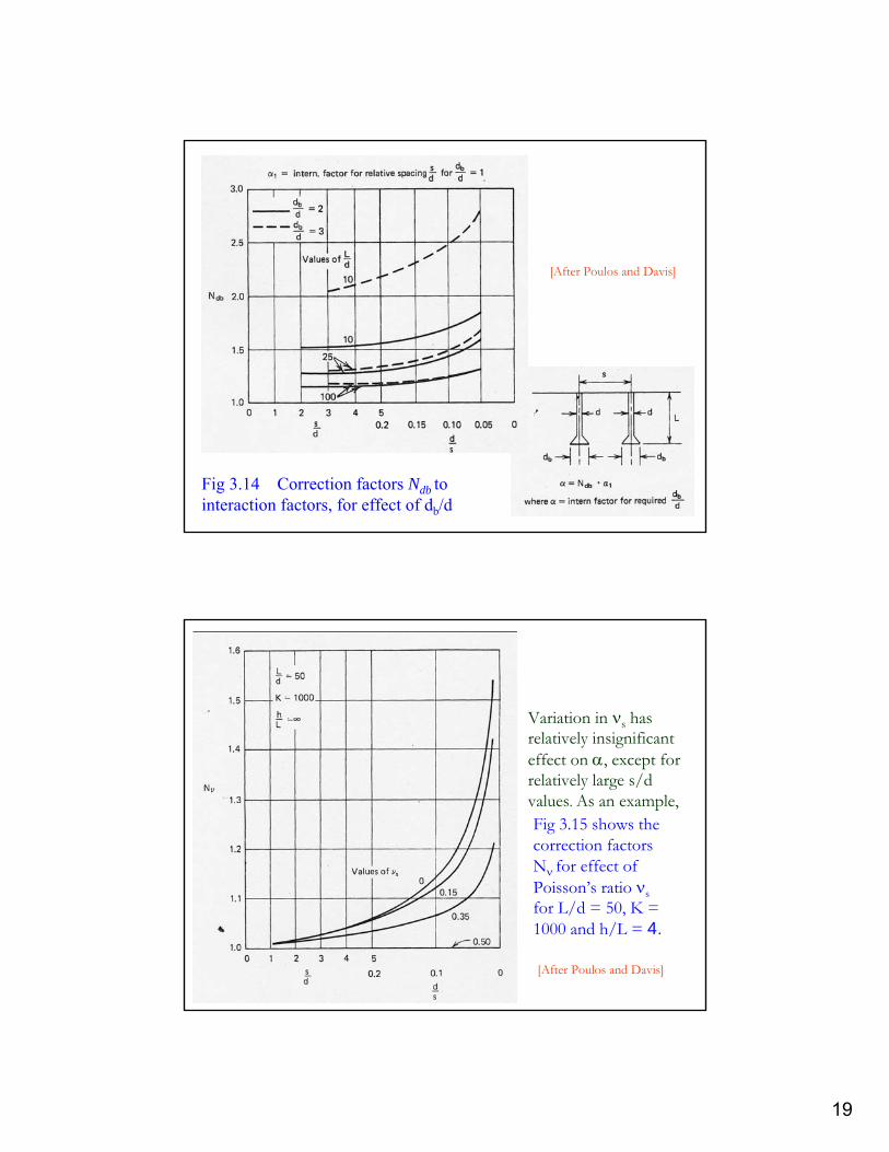
Fig 3.14 Correction factors Ndb to interaction factors, for effect of db/d
[After Poulos and Davis]
Fig 3.15 shows the correction factors Nν for effect of Poisson’s ratio νsfor L/d = 50, K = 1000 and h/L = 4.
[After Poulos and Davis]
Variation in νs has relatively insignificant effect on α, except for relatively large s/d values. As an example,
20
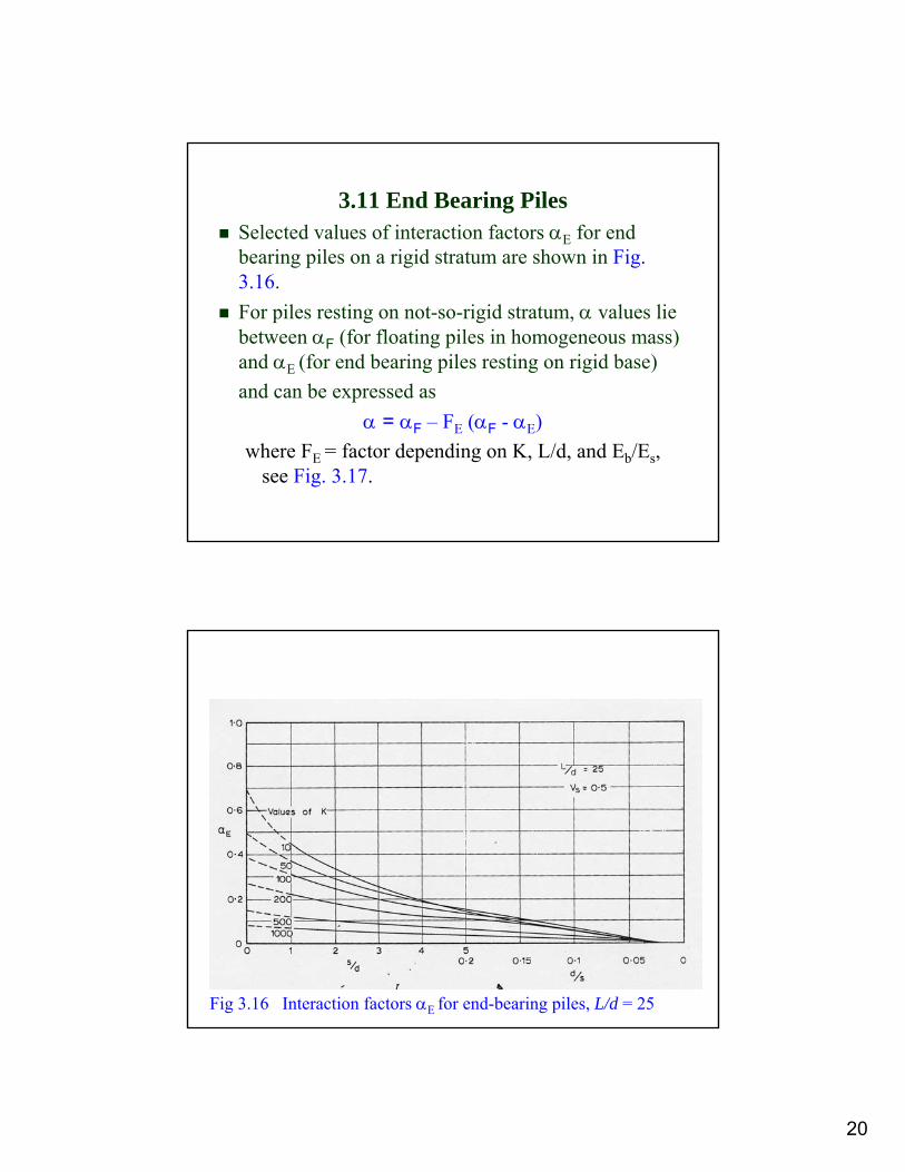
3.11 End Bearing PilesSelected values of interaction factors αE for end bearing piles on a rigid stratum are shown in Fig. 3.16.For piles resting on not-so-rigid stratum, α values lie between αF (for floating piles in homogeneous mass) and αE (for end bearing piles resting on rigid base)and can be expressed as
α = αF – FE (αF - αE) where FE = factor depending on K, L/d, and Eb/Es,
see Fig. 3.17.
Fig 3.16 Interaction factors αE for end-bearing piles, L/d = 25
[After Poulos and Davis]

21
Fig 3.17 Interaction reduction factor FE for L/d = 25
[After Poulos and Davis]
3.12 Pile-Raft Foundation
Solutions presented earlier are derived based on freestanding pile group (pile cap not resting on soil).For pile-raft foundation with the pile cap resting on soil, selected values of interaction factors αr for a pile-raft unit is given in Fig. 3.18.In the example shown in Fig. 3.18, the piles are incompressible (i.e. K = ∞) with L/d = 25, pile cap is rigid and vs = 0.5. Other solution charts are given in Poulos and Davis.
22
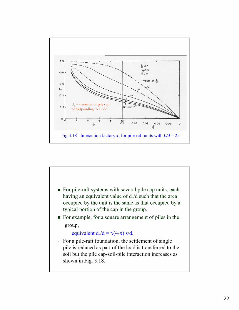
Fig 3.18 Interaction factors αr for pile-raft units with L/d = 25
[After Poulos and Davis]
dc = diameter of pile cap corresponding to 1 pile
For pile-raft systems with several pile cap units, each having an equivalent value of dc/d such that the area occupied by the unit is the same as that occupied by a typical portion of the cap in the group.For example, for a square arrangement of piles in thegroup,
equivalent dc/d = √(4/π) s/d.- For a pile-raft foundation, the settlement of single
pile is reduced as part of the load is transferred to the soil but the pile cap-soil-pile interaction increases as shown in Fig. 3.18.
23
3.13 Other considerations(a) Soil with increasing modulus with depth
α(soil with increasing modulus with depth)≈ 75 to 80% α(homogeneous soil)
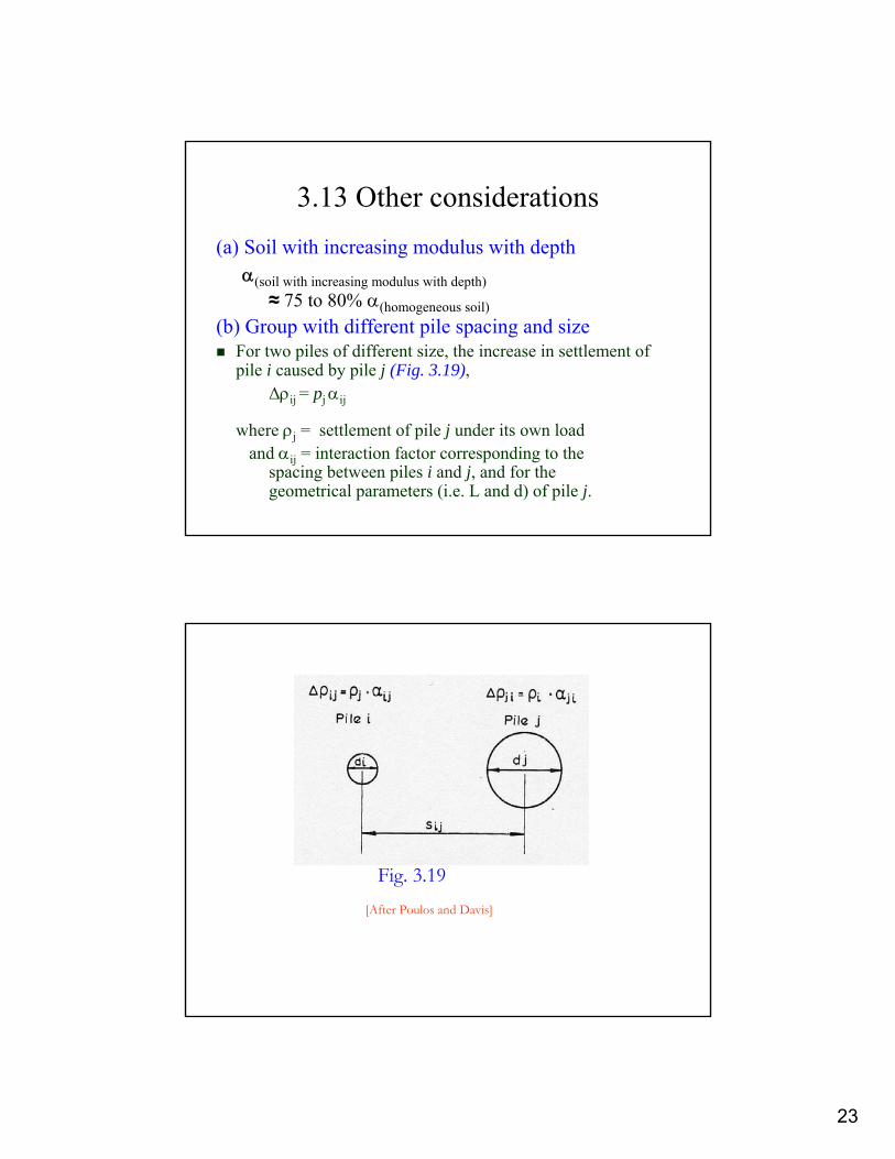
(b) Group with different pile spacing and sizeFor two piles of different size, the increase in settlement of pile i caused by pile j (Fig. 3.19),
∆ρij = pj αij
where ρj = settlement of pile j under its own loadand αij = interaction factor corresponding to the
spacing between piles i and j, and for the geometrical parameters (i.e. L and d) of pile j.
[After Poulos and Davis]
Fig. 3.19

24
(c) Effect of Underlying Compressible Strata
Extend method in Section 3.5 for pile group calculation.Overall settlement = settlement of the group in founding layer + settlement of the underlying layers caused by all piles in the group.Pile group can be assumed to be an equivalent single pier. (e.g. of the same gross plan area and of equivalent length Le)Refer to Poulos and Davis for details.
3.14 Analysis of General GroupsUse superposition of two pile interaction factors to analyse settlement behaviour of a pile group.Thus, a group of n identical piles, settlement of any pile k in the group, ρk is given as
where ρ1 = settlement of single pile under unit loadPj = load in pile j, andαkj = interaction factor for spacing between
piles k and j.
25
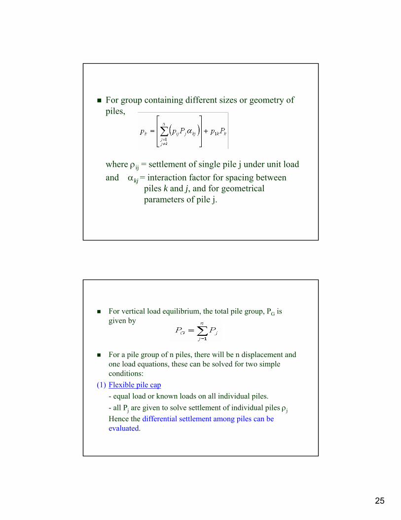
For group containing different sizes or geometry of piles,
where ρij = settlement of single pile j under unit loadand αkj = interaction factor for spacing between
piles k and j, and for geometrical parameters of pile j.
For vertical load equilibrium, the total pile group, PG is given by
For a pile group of n piles, there will be n displacement and one load equations, these can be solved for two simple conditions:
(1) Flexible pile cap- equal load or known loads on all individual piles.- all Pj are given to solve settlement of individual piles ρj
Hence the differential settlement among piles can be evaluated.
26
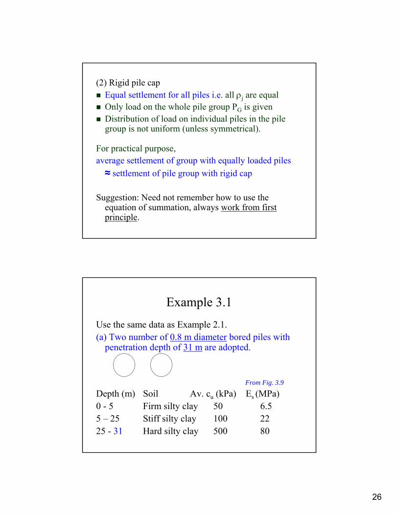
(2) Rigid pile capEqual settlement for all piles i.e. all ρj are equal Only load on the whole pile group PG is givenDistribution of load on individual piles in the pile group is not uniform (unless symmetrical).
For practical purpose, average settlement of group with equally loaded piles ≈ settlement of pile group with rigid cap
Suggestion: Need not remember how to use the equation of summation, always work from first principle.
Example 3.1Use the same data as Example 2.1. (a) Two number of 0.8 m diameter bored piles with
penetration depth of 31 m are adopted.
From Fig. 3.9
Depth (m) Soil Av. cu (kPa) Es (MPa) 0 - 5 Firm silty clay 50 6.55 – 25 Stiff silty clay 100 2225 - 31 Hard silty clay 500 80
27
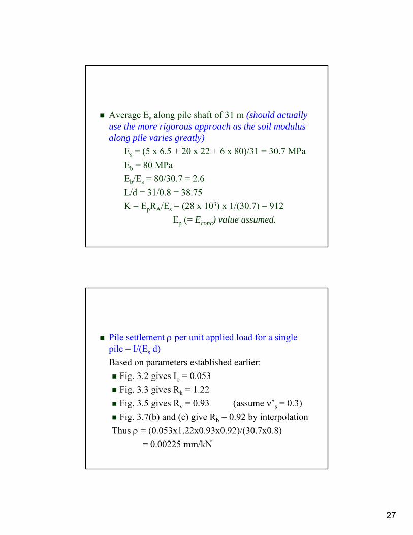
Average Es along pile shaft of 31 m (should actually use the more rigorous approach as the soil modulus along pile varies greatly)
Es = (5 x 6.5 + 20 x 22 + 6 x 80)/31 = 30.7 MPaEb = 80 MPaEb/Es = 80/30.7 = 2.6L/d = 31/0.8 = 38.75K = EpRA/Es = (28 x 103) x 1/(30.7) = 912
Ep (= Econc) value assumed.
Pile settlement ρ per unit applied load for a single pile = I/(Es d)Based on parameters established earlier:
Fig. 3.2 gives Io = 0.053Fig. 3.3 gives Rk = 1.22Fig. 3.5 gives Rν = 0.93 (assume ν’s = 0.3)Fig. 3.7(b) and (c) give Rb = 0.92 by interpolation
Thus ρ = (0.053x1.22x0.93x0.92)/(30.7x0.8)= 0.00225 mm/kN

28
Pile groupTry s/d = 2 to start withUse L/d = 25 charts (should actually interpolate from L/d = 25 & L/d = 50 charts for L/d = 38.75)Based on parameters established earlier,
Fig. 3.12 gives αF = 0.58Fig. 3.17 gives αE = 0.06 {much smaller than αF)Fig. 3.18 gives FE = 0.2
Thus α = 0.58 – 0.2(0.58 – 0.06) = 0.476 {interaction between piles is significant!}
(i) Flexible pile group
Working load on each pile = 6000/2 = 3000 kNOwing to symmetry, settlement of each pile ρi is the same = (0.00225 x 3000) mm x (1 + 0.476)
= 6.75 mm (1 + 0.476) = 9.963 mm(1 is settlement due to loading on own pile and 0.476 is the increase in settlement due to loading on the other pile)
Normally the settlement under working load should be less than 10 mm. Thus the estimated settlement is within limit!
(ii) Rigid pile capOwing to symmetry, the load on each pile is the same at 3000 kN
and hence the settlement is also the same as the flexible pile cap case.
29
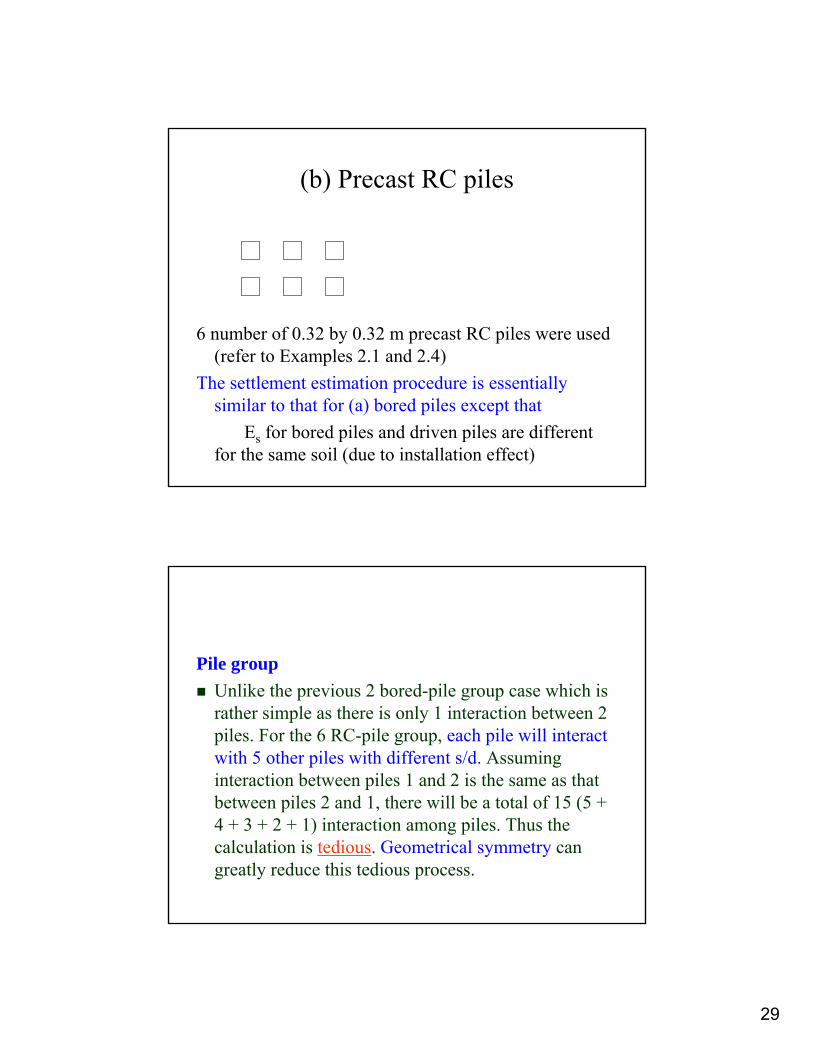
(b) Precast RC piles
6 number of 0.32 by 0.32 m precast RC piles were used (refer to Examples 2.1 and 2.4)
The settlement estimation procedure is essentially similar to that for (a) bored piles except that
Es for bored piles and driven piles are different for the same soil (due to installation effect)
Pile groupUnlike the previous 2 bored-pile group case which is rather simple as there is only 1 interaction between 2 piles. For the 6 RC-pile group, each pile will interact with 5 other piles with different s/d. Assuming interaction between piles 1 and 2 is the same as that between piles 2 and 1, there will be a total of 15 (5 + 4 + 3 + 2 + 1) interaction among piles. Thus the calculation is tedious. Geometrical symmetry can greatly reduce this tedious process.
30
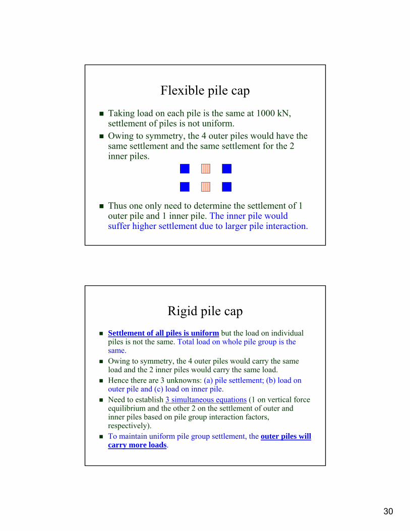
Flexible pile capTaking load on each pile is the same at 1000 kN, settlement of piles is not uniform.Owing to symmetry, the 4 outer piles would have the same settlement and the same settlement for the 2 inner piles.
Thus one only need to determine the settlement of 1 outer pile and 1 inner pile. The inner pile would suffer higher settlement due to larger pile interaction.
Rigid pile capSettlement of all piles is uniform but the load on individual piles is not the same. Total load on whole pile group is the same.Owing to symmetry, the 4 outer piles would carry the same load and the 2 inner piles would carry the same load. Hence there are 3 unknowns: (a) pile settlement; (b) load on outer pile and (c) load on inner pile.Need to establish 3 simultaneous equations (1 on vertical force equilibrium and the other 2 on the settlement of outer and inner piles based on pile group interaction factors, respectively).To maintain uniform pile group settlement, the outer piles will carry more loads.

31
3.15 Discussions on Elastic Theory
Limitations of Elastic TheoryYoung’s modulus of soil (working load)Pile group interaction (theory versus practice)Pile centre-to-centre spacingFloating piles versus end bearing pilesRigidity of pile cap (thickness and plan size of cap)Pile raft foundationRecommendations for pile design in practice
Granite
Granite (Hillview area, Singapore)
Building
32
Buildings on widely varied ground
The elevation of the base of a proposed building is shown in the previous slide. One end of the building will be on ground with relatively shallow bedrock (thus short piles) while the end will be on ground with much deeper bedrock (long piles necessary). Discuss the problems associated with the design and construction of the foundation for the building.Provide suggestions how the problems can be overcome.