cecc-x-m1 kbs c 2017-09a 8074647g1 - festo...festo cecc-x-m1-... 2017-09a english 3 english 1 safety...
TRANSCRIPT

Brief description
ControllerCECCXM1
CECCXM1MV
CECCXM1MVS1
80793492017-09a[8074647]
Controller CECC-X-M1

Festo CECC-X-M1-... 2017-09a 2
PI PROFIBUS PROFINET®, CANopen®, CODESYS®, EtherCAT®,EtherNet/IP®, IO-Link®, and MODBUS® are registered trademarks oftheir respective trademark holders in certain countries.
This product uses opensource software which is subject to the“GNU General Public License, Version 2”. The licensing conditionsof the GPL are located either in the product’s engineering tool or atthe following address: http://www.gnu.org/copyleft/gpl.html
Edition: 2017-09aOriginal instructions
© Festo SE & Co. KGRuiter Straße 8273734 EsslingenGermanyInternet: �http://www.festo.comE-Mail: �[email protected]
Festo CECC-X-M1-... 2017-09a English 3
English1 Safety
1.1 General safety information
� Observe the safety instructions in the corresponding chapters.
Special safety regulations are placed immediately before the
task instruction.
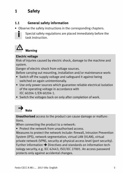
Warning
Electric voltageRisk of injuries caused by electric shock, damage to the machine and
system.
Danger of electric shock from voltage sources.
Before carrying out mounting, installation and/or maintenance work:
� Switch off the supply voltage and safeguard it against being
switched on again unintentionally.
� Use only power sources which guarantee reliable electrical isolation
of the operating voltage in accordance with
IEC�60204-1/EN�60204-1.
� Switch the voltages back on only after completion of work.
Note
Unauthorised access to the product can cause damage or malfunc
tions.
When connecting the product to a network:
� Protect the network from unauthorised access.
Measures to protect the network include: firewall, Intrusion Prevention
System (IPS), network segmentation, virtual LAN (VLAN), virtual
private network (VPN), security at physical access level (port security).
Further information � Directives and standards on information tech
nology security, e.g. IEC 62443, ISO/IEC 27001. An access password
protects only against accidental changes.
Festo CECC-X-M1-... 2017-09a English4
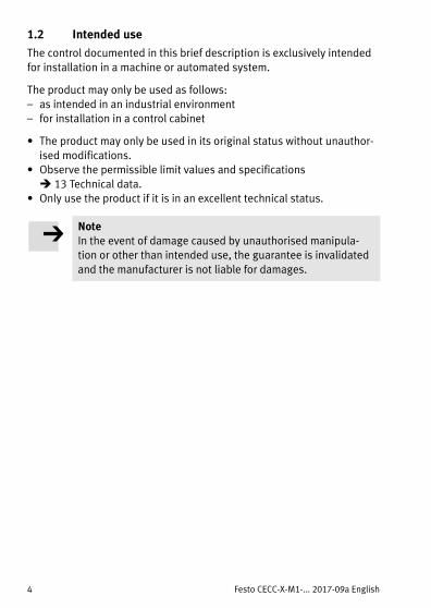
1.2 Intended use
The control documented in this brief description is exclusively intended
for installation in a machine or automated system.
The product may only be used as follows:
– as intended in an industrial environment
– for installation in a control cabinet
� The product may only be used in its original status without unauthor
ised modifications.
� Observe the permissible limit values and specifications
� 13�Technical data.
� Only use the product if it is in an excellent technical status.
NoteIn the event of damage caused by unauthorised manipula
tion or other than intended use, the guarantee is invalidated
and the manufacturer is not liable for damages.

Festo CECC-X-M1-... 2017-09a English 5
2 Requirements for product use
� Make this brief description available to the design engineer, installer
and personnel responsible for commissioning of the machine or sys
tem in which these products are used.
� Make sure that the specifications of the documentation are always
complied with. Also consider the documentation for the other com
ponents and modules � 13�Technical data.
� Take into consideration the legal regulations applicable at the installa
tion site, as well as:
– regulations and standards
– regulations of the testing organisations and insurers
– national specifications
2.1 Training of skilled personnel
The following steps must only be carried out by qualified specialists:
– mounting
– installation
– commissioning
– maintenance
– repair
The trained personnel must be familiar with:
– electrical control technology
– the applicable regulations for operating safety-engineered systems
– the applicable regulations for accident prevention and occupational
safety

Festo CECC-X-M1-... 2017-09a English6
3 Scope of delivery
– Controller CECC-X-M1-...
– This brief description
Software for the product can be found in the Festo Support
Portal � www.festo.com/sp.
4 Accessories
– Camera
– Plug assortment
Catalogue � www.festo.com/sp
Please consult your regional Festo contact if you have any technical
queries or questions regarding the accessories.
Festo CECC-X-M1-... 2017-09a English 7
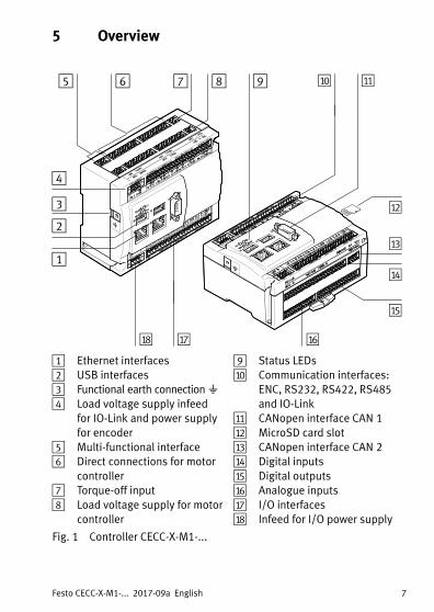
5 Overview
aF
aD
aE
4
1
2
3
5 6 7 8 aJ aA
aB
aC
9
aH aG
1 Ethernet interfaces
2 USB interfaces
3 Functional earth connection��4 Load voltage supply infeed
for IO-Link and power supply
for encoder
5 Multi-functional interface
6 Direct connections for motor
controller
7 Torque-off input
8 Load voltage supply for motor
controller
9 Status LEDs
aJ Communication interfaces:
ENC, RS232, RS422, RS485
and IO-Link
aA CANopen interface CAN�1
aB MicroSD card slot
aC CANopen interface CAN�2
aD Digital inputs
aE Digital outputs
aF Analogue inputs
aG I/O interfaces
aH Infeed for I/O power supply
Fig. 1 Controller CECC-X-M1-...

Festo CECC-X-M1-... 2017-09a English8
6 Installation
NoteDamage to the product from incorrect handling.
� Never pull out or plug in the plug connectors and inter
faces when powered.
� Observe the handling specifications for electrostatically
sensitive devices.
The product can be mounted on a H-rail or on a flat surface in any
mounting position.
� Ensure sufficient free space:
– above and below the product for connecting cables
– to the right of the product for cold-air entry and access to the Mi
croSD card slot.
81 mm
122.2 mm
bJ
aI
20 mm
bA
aI Clip
bA Distance
bJ Mounting holes
Fig. 2

Festo CECC-X-M1-... 2017-09a English 9
6.1 Mounting on H-rail
1. Insert the product into the H-rail.
2. Press the product in the direction of the arrow until it audibly engages.
6.2 Dismounting from H-rail
1. Remove the plug connector on the underside of the product.
2. Unlock the product via the clip � Fig. 2�aI ��.
Use a suitable tool, e.g. a screwdriver.
3. Remove the product from the H-rail.
6.3 Mounting onto mounting surface
Note
Damage to the product caused by mounting on uneven or flexible
surfaces.
� Only mount the product on an even, torsionally rigid surface.
1. Drill two mounting holes bJ� in the mounting surface (�4.5 mm,
spacing � Fig. 2 – hole pattern).
2. Secure the product in place with two M4 screws.
– Screw head diameter: 7 mm
– Max. tightening torque: 0.8 Nm
6.4 Dismounting from mounting surface
1. Loosen two M4 screws.
2. Remove the product from the mounting surface.
Additional information regarding installation and commissioning
can be found in the Festo Support Portal � www.festo.com/sp.

Festo CECC-X-M1-... 2017-09a English10
7 Status LEDsThe product is equipped with the following status LEDs � Fig. 1 9:
Status LED Meaning Status LED Meaning
Run Application status Net Device detected
Error Error Mod Reserved
Fig. 3
8 Power supplies
Note� Use an external overload protection for the power supply
of the device.
� Pay attention to the required current consumption.
8.1 Power supply [X1]for device, digital/analogue inputs and motor controller direct connection (logic)
Residual current for all supplied ports: 750 mAof which intrinsic current consumption: �200 mA
Terminal Port Comments
X1.1 24 U+ power supply
X1.2 0 U– load
X1.3 � Functional earth
X1.4 – Not connected
Fig. 4

Festo CECC-X-M1-... 2017-09a English 11
8.2 Power supply [X5] for digital outputs
Residual current for all supplied ports: �5 A
Terminal Port Comments
X5.1 24 U+ power supply
X5.2 0 U– load
Fig. 5
8.3 Load voltage supply [X21] for motor controller
Residual current for all supplied ports: �8 A
Terminal Comments
X21.1 24 V/48 V load voltage supply feed
X21.2 GND
Fig. 6
Note
Damage to the product in case of overload.
If there is a load on all digital outputs of 0.5 A each, the residual cur
rent can be exceeded as soon as additional consuming devices are
used.
� Consider all current loads.
� For special configurations, contact the local Festo service.

Festo CECC-X-M1-... 2017-09a English12
8.4 Load voltage supply [X11] for IO-Link
This port is used for the power supply of an IO-Link device that is con
nected via the IO-Link master port.
Current consumption for IO-Link: �0.75 A
Note
Damage to the product in the event of a mix-up of the connecting pins.
� When establishing the load voltage supply for the IO-Link master
port, make sure that only connecting pins X11.1 and X11.2 are
used.
Terminal Port Comments Internalconnection
X11.1 24 UA+ Infeed for IO-Link master port X15.4
X11.2 0 UA– Infeed for IO-Link master port X15.5
Fig. 7
8.5 Power supply [X11] for encoder
Encoder current consumption: �0.3 A
Terminal
Port Comments
X11.3 UG Encoder power supply (ground)
X11.4 UE Encoder power supply (5 V)
Fig. 8

Festo CECC-X-M1-... 2017-09a English 13
9 Interfaces, front
[X6][X10][X8]
[X1]
[X9][X7]
[X11] [X12] [X13] [X14] [X15] [X16]
[X2] [X3] [X4] [X5]
Fig. 9
9.1 I/O interface [X2, X3, X4]
Terminal Comments
X2.0 … X2.1 2 high-speed digital inputs (200 kHz)
X2.2 … X2.71),2) 6 digital inputs (1 kHz, IEC type�1)
X3.0 … X3.5 6 digital inputs (1 kHz, IEC type�1)
X4.0 … X4.73) 8 digital outputs (0.7 A per channel, PNP, SSR4))
1) X2.2 and X2.3 optionally also serve as MachineVision inputs (e.g. Trigger)
2) X2.3 also serves as a latch input for the encoder via the multiple interface X14
3) X4.0 ... X4.2 optionally also serve as MachineVision outputs (e.g. flash output)
4) SSR: Solid State Relay
Fig. 10

Festo CECC-X-M1-... 2017-09a English14
9.2 CANopen interface CAN�1 [X6]
Pin Port Comments
1 – Not connected
2 CAN1_L1) CANBus signal�1 (dominant low)
3 CAN_GND CAN Ground
4 – Not connected
5 CAN_SHLD Connection to functional earth
6 CAN_GND CAN Ground (optional)
7 CAN1_H1) CANBus signal�1 (dominant high)
8 – Not connected
9 – Not connected
1) For connection of the device at the end of the line: Connect Pin2 and Pin7 via a resistor.
A corresponding plug with resistor (120 Ω/0.25 W) can be found in Festo's accessor
ies�� www.festo.com/catalogue
Fig. 11
9.3 USB interfaces [X7, X9]
The USB interfaces � Fig. 1 2 are compatible with the USB 3.0 and
USB�2.0 standards. They are suitable for USB plug type A.
The following functions are supported (cable length� 3 m):
– General data storage
– Connection of a camera
– Connection of hardware extensions
Note
Damage to the product.
� Only use USB components with a current consumption �0.9 A.
Please consult your regional Festo contact if you have any queries re
garding the extensions.
Festo CECC-X-M1-... 2017-09a English 15
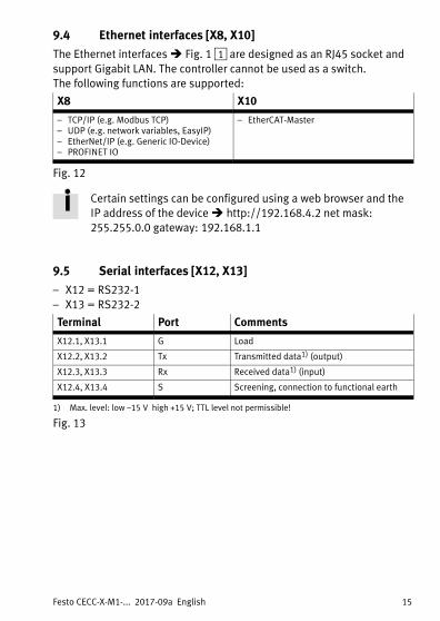
9.4 Ethernet interfaces [X8, X10]
The Ethernet interfaces � Fig. 1 1 are designed as an RJ45 socket and
support Gigabit LAN. The controller cannot be used as a switch.
The following functions are supported:
X8 X10
– TCP/IP (e.g. Modbus TCP)– UDP (e.g. network variables, EasyIP)– EtherNet/IP (e.g. Generic IODevice)– PROFINET IO
– EtherCATMaster
Fig. 12
Certain settings can be configured using a web browser and the
IP address of the device � http://192.168.4.2 net mask:
255.255.0.0 gateway:�192.168.1.1
9.5 Serial interfaces [X12, X13]
– X12 = RS232-1
– X13 = RS232-2
Terminal Port Comments
X12.1, X13.1 G Load
X12.2, X13.2 Tx Transmitted data1) (output)
X12.3, X13.3 Rx Received data1) (input)
X12.4, X13.4 S Screening, connection to functional earth
1) Max. level: low –15�V high +15�V; TTL level not permissible!
Fig. 13

Festo CECC-X-M1-... 2017-09a English16
9.6 Multiple interface for encoder/RS422/RS485 [X14]
Note
Simultaneous use of the interfaces is not possible.
� Only use the ports of one interface � Fig. 14.
Terminal Port Encoder RS4221) RS4851)
X14.1 G Load
X14.2 A+ Track A+ Transmitted data + 2) Transmitted/received data + 2)
X14.3 A– Track A�– Transmitted data – 2) Transmitted/received data�– 2)
X14.4 B+ Track B+ Received data + 3) –
X14.5 B– Track B�– Received data – 3) –
X14.6 N+ Zero track+ – –
X14.7 N– Zero track– – –
X14.8 S Screening, connection to functional earth
1) Permissible data rate �1 MHz
2) If the device is connected at the end of the cable: Connect terminals X14.2 and X14.3 via
resistor�(120 Ω/0.25 W).
3) If the device is connected at the end of the cable:
Connect terminals X14.4 and X14.5 via resistor�(120 Ω/0.25 W).
Fig. 14

Festo CECC-X-M1-... 2017-09a English 17
9.7 Communication interface for IO-Link [X15, X16]
IO-Link Master
Terminal Port Comments
X15.1 L+ 24 V
X15.2 C/Q IO-Link communication signal
X15.3 L– 0 V
X15.4 24 UA+
X15.5 0 UA–
Fig. 15
IO-Link device
Terminal Port Comments
X16.1 L+ 24 V
X16.2 C/Q IO-Link communication signal
X16.3 L– 0 V
Fig. 16
Festo CECC-X-M1-... 2017-09a English18
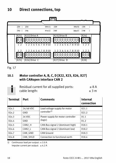
10 Direct connections, top
[X21] [X24]
[X25] [X28]
[X23] Drive�B[X22] Drive�A
[X27] Drive��D[X26] Drive��C
1 2 3 4 5 6 7 8 9 10
1 2 3 4 5 6 7 8 9 10
1 2 3 4 5 6 7 8 9 10
1 2 3 4 5 6 7 8 9 10
1 2 3
1 2 3
1 2
1 2
Fig. 17
10.1 Motor controller A, B, C, D [X22,�X23,�X26,�X27]with CANopen interface CAN�2
Residual current for all supplied ports: �8 Acable length: �3 m
Terminal Port Comments Internalconnection
X2x.1 24/48 VDC Load voltage supply for motor
controller1)X21.1
X2x.2 GND X21.2
X2x.3 24 VDC Power supply for motor controller
(logic)
X1.1
X2x.4 GND X1.2
X2x.5 CAN2_H CANBus signal�2 (dominant high) X18.1
X2x.6 CAN2_L CANBus signal�2 (dominant low) X18.2
X2x.7 CAN_GND CAN Ground X18.3
X2x.8 CAN_SHLD Connection to functional earth X18.4
1) Continuous load per output: �2.0 A
Impulse current per output: �4.2 A

Festo CECC-X-M1-... 2017-09a English 19
Terminal Port Comments Internalconnection
X2x.9 GPIO Home signal (digital in) X17.0.2/X17.1.2 2)
Multi-functional signal X24.2/X28.2 3)
X2x.10 GND Power supply (logic) X1.2
2) Home signal: X22.9 (drive�A) at X17.0.2; X26.9 (drive�C) at X17.1.2
3) Multi-functional signal: X23.9 (drive�B) at X24.2; X27.9 (drive�D) at X28.2
Fig. 18
10.2 Multi-functional interface [X24, X28]
Terminal Port Comments
X2x.1 24 VDC Power supply
X2x.2 Signal Multi-functional signal
X2x.3 GND Load
Fig. 19
10.3 Torque-off input [X25]
Terminal Port Comments
X25.1 Signal Torque-off input
X25.2 24 VDC Power supply
Fig. 20
Load voltage supply [X21]�� 8.3.

Festo CECC-X-M1-... 2017-09a English20
11 Direct connections, bottom
[X19] Analogue input Digital output [X20]
[X17] Digital input CAN 2 [X18]
0.1 1.1 2.1 3.1 4.1 5.1 6.1 7.1 1 2 3 4
0.1 1.1 3.12.1 0.1 1.1 2.1 3.1 4.1 5.1 6.1 7.1
Fig. 21
11.1 Digital inputs [X17]
The digital inputs, configured in 3-wire connection technology, are notgalvanically separated. The ground potential for all inputs relates to GND
of the power supply [X1].
� Always use 3 adjacent terminals when connecting a sensor with a
3-wire configuration.
Terminal Port Comments
X17.0.1 24 VDC Connection for digital sensor�1
(1 kHz, IEC type�1)X17.0.2 Signal�1 / home signal for drive A
X17.0.3 GND logic
X17.1.1 24 VDC Connection for digital sensor�2
(1 kHz, IEC type�1)X17.1.2 Signal�2 / home signal for drive C
X17.1.3 GND logic
X17.2.1 24 VDC Connection for digital sensor�3
(1 kHz, IEC type�1)X17.2.2 Signal 3
X17.2.3 GND logic

Festo CECC-X-M1-... 2017-09a English 21
Terminal CommentsPort
X17.3.1 24 VDC Connection for digital sensor�4
(1 kHz, IEC type�1)X17.3.2 Signal 4
X17.3.3 GND logic
X17.4.1 24 VDC Connection for digital sensor�5
(1 kHz, IEC type�1)X17.4.2 Signal 5
X17.4.3 GND logic
X17.5.1 24 VDC Connection for digital sensor 6
(1 kHz, IEC type�1)X17.5.2 Signal 6
X17.5.3 GND logic
X17.6.1 24 VDC Connection for digital sensor�7
(1 kHz, IEC type�1)X17.6.2 Signal 7
X17.6.3 GND logic
X17.7.1 24 VDC Connection for digital sensor�8
(1 kHz, IEC type�1)X17.7.2 Signal 8
X17.7.3 GND logic
Fig. 22
The inputs can be adjusted for PNP or NPN sensors.
Configuration is effected via CoDeSys parameters in the control
project for all inputs together.
11.2 CANopen interface CAN�2 [X18]
Terminal Port Comments
X18.1 CAN2_H1) CANBus signal�2 (dominant high)
X18.2 CAN2_L1) CANBus signal�2 (dominant low)
X18.3 CAN_GND CAN Ground
X18.4 CAN_SHLD Connection to functional earth
1) No terminating resistor necessary; ports are connected internally via a resistor.
Fig. 23

Festo CECC-X-M1-... 2017-09a English22
11.3 Analogue inputs [X19]
The analogue inputs, configured in 3-wire connection technology, are notgalvanically separated. The ground potential for all inputs relates to GND
of the power supply [X1].
An incoming signal is digitised with a 14 bit resolution.
Terminal Port Comments
X19.0.1 24 VDC Port analogue sensor 1
(0 ... 10 V; 0 ... 20 mA)X19.0.2 Signal
X19.0.3 GND
X19.1.1 24 VDC Port analogue sensor 2
(0 ... 10 V; 0 ... 20 mA)X19.1.2 Signal
X19.1.3 GND
X19.2.1 24 VDC Port analogue sensor 3
(0 ... 10 V; 0 ... 20 mA)X19.2.2 Signal
X19.2.3 GND
X19.3.1 24 VDC Port analogue sensor 4
(0 ... 10 V; 0 ... 20 mA)X19.3.2 Signal
X19.3.3 GND
Fig. 24
The inputs can be operated either with voltage signal (0 ... 10 V)
or current signal (0�... 20 mA).
Configuration is made via CODESYS parameters in the control
project for each input separately.

Festo CECC-X-M1-... 2017-09a English 23
11.4 Digital outputs [X20]
The digital outputs, configured in 2-wire connection technology, are
galvanically separated. The current load for each output is 0.5 A.
The ground potential for all outputs relates to GND of the power sup
ply [X5].
All outputs are protected against short circuit and thermal overload.
The outputs can be set to PNP or NPN circuitry.
Configuration is effected via CoDeSys parameters in the control
project for all inputs together.
24 V IO
GND IO
P
N
X5.1
X5.2
X20.x.1
X20.x.2
PNP circuit
24 V IO
GND IO
P
N
X5.1
X5.2
X20.x.1
X20.x.2
NPN circuit
Fig. 25
� Always use 2 adjacent terminals when connecting a consumer.
Terminal Port Comments
X20.0.1 Signal P Port output 1
(0.5 A per channel, SSR1))X20.0.2 Signal N
X20.1.1 Signal P Port output 2
(0.5 A per channel, SSR)X20.1.2 Signal N
X20.2.1 Signal P Port output 3
(0.5 A per channel, SSR)X20.2.2 Signal N
X20.3.1 Signal P Port output 4
(0.5 A per channel, SSR)X20.3.2 Signal N
1) SSR: Solid State Relay

Festo CECC-X-M1-... 2017-09a English24
Terminal CommentsPort
X20.4.1 Signal P Port output 5
(0.5 A per channel, SSR1))X20.4.2 Signal N
X20.5.1 Signal P Port output 6
(0.5 A per channel, SSR)X20.5.2 Signal N
X20.6.1 Signal P Port output 7
(0.5 A per channel, SSR)X20.6.2 Signal N
X20.7.1 Signal P Port output 8
(0.5 A per channel, SSR)X20.7.2 Signal N
1) SSR: Solid State Relay
Fig. 26
12 Port on side
12.1 Mass storage card slot
� Fig. 1 aB��
Supported MicroSD cards– microSD
– microSD HC
– microSD XC
Supported functions– Storage of boot projects and check programs (only�CECC-
X-M1-MV/-S1)
– General data storage

Festo CECC-X-M1-... 2017-09a English 25
13 Technical data
Controller CECC-X-M1-...
Operating voltage [X1, X5] [V�DC] 19.2 … 30
Operating voltage [X21] [V�DC] 19.2 … 50
Current consumption nominal at 24 VDC [mA] 200
Integrated brake chopper
Voltage limitation switch-on
threshold
[V] Operating voltage [X21] +�2.0
Voltage limitation switch-off
threshold
[V] Operating voltage [X21] +�0.5
Nominal power [W] 18
Continuous power [W] �5
Pulse power with pulse frequency
1 Hz (switch-on duration �10 %)
[W] �50
Braking resistor [Ω] 15
Protection against incorrect polarity No
Certification RCM
CE marking � Declaration of conformity
� www.festo.com/sp
in accordance with EU EMC Direct
ive 1),2)
USB cable length [m] �3
Motor cable length [m] �3
Other cable lengths [m] �10
Degree of protection IP20
Protection class III
Vibration and shock resistance (in ac
cordance with IEC/EN 60068-2-6)
SL1 3)
Mass storage devices
Supported types microSD, microSDHC, microSDXC,
USB
Capacity [GByte] �32
File system FAT32
1) The product is intended for use in industrial environments.
Measures for interference suppression may need to be implemented in residential areas.
2) The product is classified in zone A in accordance with EN 61131-2:2007.
3) ��13.2 Explanation on vibration and shock – severity level

Festo CECC-X-M1-... 2017-09a English26
Controller CECC-X-M1-...
Analogue inputs
Input signal [U] 0 ... 10 V
Input signal [I] 0 ... 20 mA
Resolution Bit 14
Hardware
Processor (CPU) Dual core, 2 x 866 MHz
Total main memory MB 512
Memory for project data (temporary) MB 19.5
Memory for project data (permanent) MB 8
Remanent memory � 13.1 KB 4
Ambient temperature [°C] 0 … 55
Storage temperature [°C] –25 … 70
Product weight [g] 410
Fan noise LpAeq (1 m distance) [dB(A)] 35.7
1) The product is intended for use in industrial environments.
Measures for interference suppression may need to be implemented in residential areas.
2) The product is classified in zone A in accordance with EN 61131-2:2007.
3) ��13.2 Explanation on vibration and shock – severity level
Fig. 27
13.1 Remanent variables
A maximum of 4096 bytes are available on the controller for storing re
manent variables. They are automatically distributed based on the vari
able declaration within the application.
The following sample combinations for distributing the remanent
memory are possible.
RETAIN variable PERSISTENT RETAIN variable
4096 Byte 0 bytes (only if there is no PERSISTENT variable list)
0 bytes 4052 (44 bytes for identification)
300 bytes 4052 – 300 bytes = 3752 bytes (44 bytes for identification)
x bytes 4052 – x bytes (44 bytes for identification)
Fig. 28
Festo CECC-X-M1-... 2017-09a English 27
Note
� Make sure during programming that the total size of all the reman
ent data does not exceed the maximum available range of
4096 bytes.
This will avoid errors when transferring an application to the control
ler.
Additional information can be found in the Festo Support
Portal � www.festo.com/sp.

Festo CECC-X-M1-... 2017-09a English28
13.2 Explanation on vibration and shock – severity level
Vibration load
Frequency range [Hz] Acceleration [m/s2] Deflection [mm]
SL1 SL2 SL1 SL2 SL1 SL2
2 … 8 2 … 8 – – ±3.5 ±3.5
8 … 27 8 … 27 10 10 – –
27 … 58 27 … 60 – – ±0.15 ±0.35
58 … 160 60 … 160 20 50 – –
160 … 200 160 … 200 10 10 – –
Fig. 29
Shock load
Acceleration [m/s2] Duration [ms] Shocks per direction
SL1 SL2 SL1 SL2 SL1 SL2
±150 ±300 11 11 5 5
Fig. 30
Continuous shock load
Acceleration [m/s2] Duration [ms] Shocks per direction
±150 6 1000
Fig. 31