cefil’air - technetics grouptechnetics.com/bin/cefilair_english_low res.pdf · cefil’air ®...
TRANSCRIPT
Meeting Your Critical Sealing Requirements.
CEFIL’AIR®
Inflatable Seals
INTRODUCTION
When faced with the problem of sealing between parts, which
move in relation to one another and are capable of being
connected and disconnected at will, the easiest, safest and
most effective technique to use is pneumatic seals.
CEFIL’AIR® seals, which are expanded and retracted by a
pneumatic process, have been designed to meet multiple
applications. CEFIL’AIR® inflatable seals bring wider
possibilities of use as a result of its patented design
employing modern techniques and the most advanced
elastomers.
These seals can satisfy the highest demands of temperatures
from -60 °C to +220 °C, as well as higher temperatures during
short periods. They can also withstand pressures from dynamic
vacuum (1,33.10-6 Bar) to several dozen Bars (102 Bar and
more). CEFIL’AIR® inflatable seals can be used in all sectors of
industry including advanced techniques and
scientific research.
APPLICATIONS
CEFIL’AIR® inflatable seals are fitted
in the following cases where sealing,
handling, or locking is required:
• movable cofferdam bulkheads
• storage containers
• transport containers
• leaktight panels
(naval, aerospacial industry)
• nuclear vessels
(equipment or personnel chambers)
• isothermal chambers
• clean rooms
• sliding or quick-locking doors
(autoclaves, sterilisers)
• centrifugal filters
(access doors and drainage hoppers)
• aircraft access doors
• cockpit canopies
• portholes
• cofferdams
• pneumatic conveyors
(bagging hoppers, valve gates)
• phonic isolation
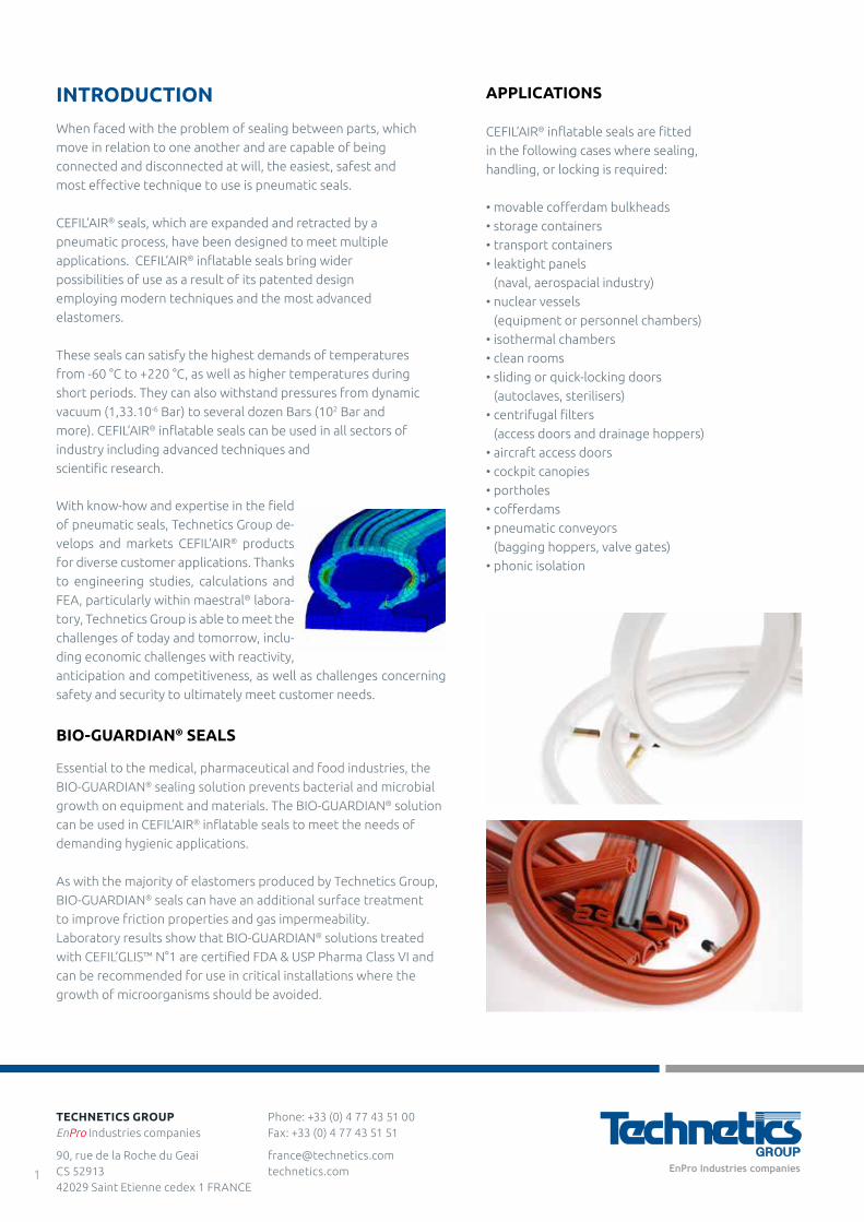
With know-how and expertise in the field
of pneumatic seals, Technetics Group de-
velops and markets CEFIL’AIR® products
for diverse customer applications. Thanks
to engineering studies, calculations and
FEA, particularly within maestral® labora-
tory, Technetics Group is able to meet the
challenges of today and tomorrow, inclu-
ding economic challenges with reactivity,
anticipation and competitiveness, as well as challenges concerning
safety and security to ultimately meet customer needs.
BIO-GUARDIAN® SEALS
Essential to the medical, pharmaceutical and food industries, the
BIO-GUARDIAN® sealing solution prevents bacterial and microbial
growth on equipment and materials. The BIO-GUARDIAN® solution
can be used in CEFIL’AIR® inflatable seals to meet the needs of
demanding hygienic applications.
As with the majority of elastomers produced by Technetics Group,
BIO-GUARDIAN® seals can have an additional surface treatment
to improve friction properties and gas impermeability.
Laboratory results show that BIO-GUARDIAN® solutions treated
with CEFIL’GLIS™ N°1 are certified FDA & USP Pharma Class VI and
can be recommended for use in critical installations where the
growth of microorganisms should be avoided.
Phone: +33 (0) 4 77 43 51 00 Fax: +33 (0) 4 77 43 51 51
[email protected] technetics.com
TECHNETICS GROUPEnPro Industries companies
90, rue de la Roche du Geai CS 52913 42029 Saint Etienne cedex 1 FRANCE
1
For specific uses which need reinforced manufacturing (textiles, hight performance aramid fibers) or expanded profiles, see pages 12
and 13 and please contact our technical department.
When free, CEFIL’AIR® seals must not be inflated above ≥ 0,8 to1,5 bar (according to the type of the profile). When fitted in
a groove, they are perfectly leaktight for an inflation pressure of 1,25 to 1,45 times the pressure to seal (Ps). The maximum
inflation pressure (Pi) which the seals can withstand depends on the clearance (J) between the supporting frame and the moving
panel (see profiles on pages 4-5). The inflation pressure (Pi) can be higher if clearance is reduced. CEFIL’AIR® seals are designed
to provide tightness on pressurised equipment. This creates a lateral force on the seal, which tends to force it either towards the
outside (equipment under pressure) or towards the inside of the equipment (equipment under vacuum).
a) Equipment under vacuum (P0-Ps>0)
The condition of the surfaces in contact, as well as the completion of the assembly operation, make it possible for CEFIL’AIR® seals
to withstand a vacuum of 10-3 Torr (dynamic vacuum).
b) Equipment under pressure (P0-Ps<0)
With an internal pressure created by gas or a controlled atmosphere, the strength is directly linked to the clearances,
deformation of the contact faces and the pressurisation of the seal. In these applications, it is always necessary to reduce
dimension (J) to a minimum, restricting the surface to which the pressure of the enclosure (Ps) will be applied, in order to reduce
the radial component or, depending on the arrangement, the axial component, as far as possible as this tends to force the seal
outwards. Generally, the ratio Ps-Po/Pi is of 0,7 to 0,2 but with the limits laid down in the table concerning profiles (pages 4-5).
MANUFACTURE
CEFIL’AIR® inflatable seals are made by joining together extruded or moulded sections. This connection is made in our workshops,
which ensures perfect continuity while at the same time reducing any stresses in the joint to a minimum.
This method provides substantial flexibility with regard to the geometry of the sections. There are two types of standard profiles
and a series of special profiles that are used in numerous applications, i.e. sealing, locking or gripping during automatic handling have been created.
OPERATION
CEFIL’AIR® seals have no textile reinforcement or expansion system. Their expansion, like their retraction, is obtained through the
combined effects of the walls of the seal forming elastic arms. The seals, which are produced from elastomers with a high
modulus of elasticity and considerable elongation and fitted in grooves, are restricted to low work rates. As a result, they are
protected against risks of bursting, so it is necessary to observe the fitting dimensions (table, pages 4-5).
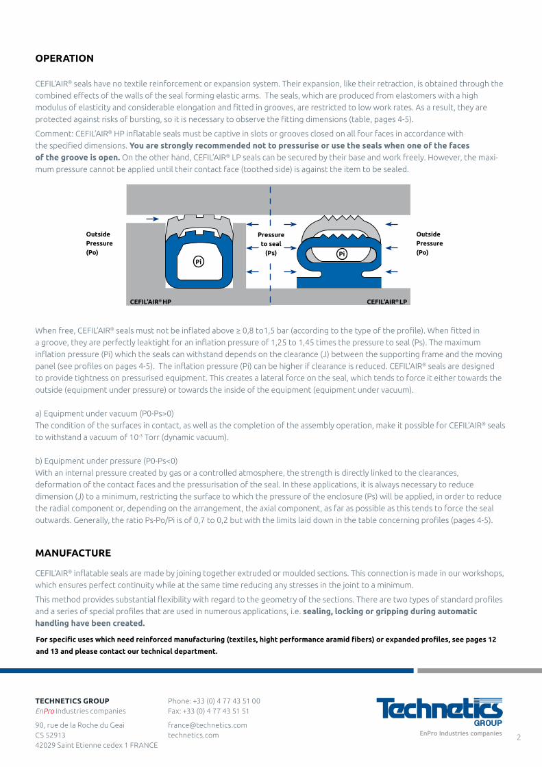
Comment: CEFIL’AIR® HP inflatable seals must be captive in slots or grooves closed on all four faces in accordance with
the specified dimensions. You are strongly recommended not to pressurise or use the seals when one of the faces of the groove is open. On the other hand, CEFIL’AIR® LP seals can be secured by their base and work freely. However, the maxi-
mum pressure cannot be applied until their contact face (toothed side) is against the item to be sealed.
CEFIL’AIR® HP
PiPi
CEFIL’AIR® LP
Outside Pressure (Po)
Outside Pressure (Po)
Pressure to seal
(Ps)
Phone: +33 (0) 4 77 43 51 00 Fax: +33 (0) 4 77 43 51 51
[email protected] technetics.com
TECHNETICS GROUPEnPro Industries companies
90, rue de la Roche du Geai CS 52913 42029 Saint Etienne cedex 1 FRANCE
2
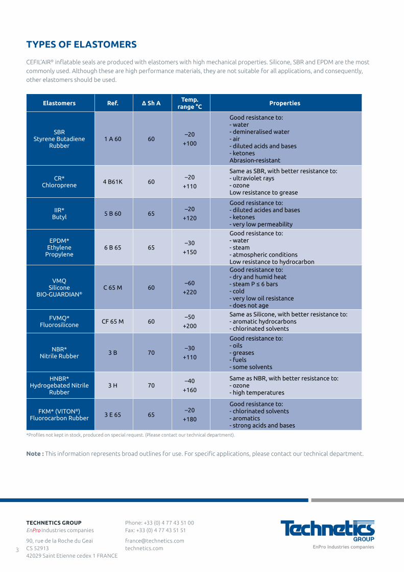
TYPES OF ELASTOMERS
CEFIL’AIR® inflatable seals are produced with elastomers with high mechanical properties. Silicone, SBR and EPDM are the most
commonly used. Although these are high performance materials, they are not suitable for all applications, and consequently,
other elastomers should be used.
*Profiles not kept in stock, produced on special request. (Please contact our technical department).
Note : This information represents broad outlines for use. For specific applications, please contact our technical department.
Elastomers Ref. Δ Sh A Temp.range °C Properties
SBRStyrene Butadiene
Rubber1 A 60 60
–20
+100
Good resistance to:- water- demineralised water- air- diluted acids and bases- ketonesAbrasion-resistant
CR*Chloroprene 4 B61K 60
–20
+110
Same as SBR, with better resistance to:- ultraviolet rays- ozoneLow resistance to grease
IIR*Butyl 5 B 60 65
–20
+120
Good resistance to:- diluted acides and bases- ketones- very low permeability
EPDM*Ethylene
Propylene6 B 65 65
–30
+150
Good resistance to:- water- steam - atmospheric conditionsLow resistance to hydrocarbon
VMQSilicone
BIO-GUARDIAN®C 65 M 60
–60
+220
Good resistance to:- dry and humid heat- steam P ≤ 6 bars- cold- very low oil resistance- does not age
FVMQ*Fluorosilicone CF 65 M 60
–50
+200
Same as Silicone, with better resistance to:- aromatic hydrocarbons- chlorinated solvents
NBR*Nitrile Rubber 3 B 70
–30
+110
Good resistance to:- oils- greases- fuels- some solvents
HNBR*Hydrogebated Nitrile
Rubber3 H 70
–40
+160
Same as NBR, with better resistance to:- ozone- high temperatures
FKM* (VITON®)Fluorocarbon Rubber 3 E 65 65
–20
+180
Good resistance to:- chlorinated solvents- aromatics- strong acids and bases
Phone: +33 (0) 4 77 43 51 00 Fax: +33 (0) 4 77 43 51 51
[email protected] technetics.com
TECHNETICS GROUPEnPro Industries companies
90, rue de la Roche du Geai CS 52913 42029 Saint Etienne cedex 1 FRANCE
3
ASSEMBLY
In order to obtain the full
expansion and retraction of
the seal, as well as guarantee
its maximum efficiency, the
minimum curve radii in the
corners must be in accordance
with the opposite table. The
sketches define the reference
line of the radius at the bottom
of the groove according to
the position of the curve in
relation to the direction of the
expansion.
Please consult our technical department for small sized circular seals.
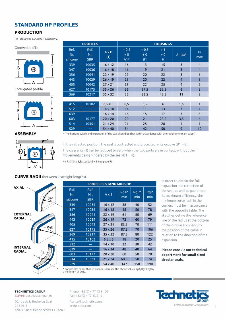
* The housing width and expansion of the seal should be checked in accordance with the requirements on page 7.
STANDARD HP PROFILESPRODUCTION(1) Tolerances ISO 3302-1 category 2.
Grooved profile
Corrugated profile
PROFILES HOUSINGS
Ref.Nr.
silicone
Ref.Nr.
SBR
A x B(1)
+ 0,5+ 0A1*
+ 0,5+ 0B1
+ 1+ 0H
J max*Pi
max
339 10035 16 x 12 16 13 15 3 4
347 10036 16 x 18 16 19 21 3 4
356 10041 22 x 19 22 20 22 3 6
443 10039 26 x 19 26 20 23 4 6
405 10042 27 x 21 27 22 25 4 6
627 10175 35 x 26 35 27,5 32,5 6 8
369 10217 35 x 32 35 33,5 43,5 11 8
PROFILES STANDARDS HP
Ref.Nr.
silicone
Ref.Nr.
SBRA x B
RgA*min
RgE*min
RgI*min
339 10035 16 x 12 38 40 52
347 10036 16 x 18 48 50 78
356 10041 22 x 19 61 50 69
443 10039 26 x 19 73 60 79
405 10042 27 x 21 83,5 70 111
627 10175 35 x 26 87,5 70 106
369 10217 35 x 32 87,5 80 122
415 10102 6,5 x 5 18 20 25
512 --- 14 x 10 32 30 42
639 --- 16 x 14 48 40 64
603 10177 20 x 20 60 50 70
514 10331 21 x 24 60,5 50 74
529 --- 54 x 40 147 150 190
415 10102 6,5 x 5 6,5 5,5 6 1,5 1
512 --- 14 x 10 14 11 13 3 4
639 --- 16 x 14 16 15 17 3 5
603 10177 20 x 20 20 21 23,5 3,5 6
514 10351 21 x 24 21 25 28 4 7
529 --- 54 x 40 54 42 50 9 10
B H
A
B
A
H
RgA
RgE
RgI
CURVE RADII (between 2 straight lengths).
AXIAL
INTERNALRADIAL
EXTERNALRADIAL
Pi
Pi
In the retracted position, the seal is contracted and protected in its groove (B1 > B).
The clearance (J) can be reduced to zero when the two parts are in contact, without their
movements being hindered by the seal (B1 = H).
* √ Ra 3,2 to 6,3. standard N8 (see page 9).
* For profiles other than in silicone, increase the above values RgA/RgE/RgI by a minimum of 20%.
B1H
J
*
*
*
A1
*
Pi
Phone: +33 (0) 4 77 43 51 00 Fax: +33 (0) 4 77 43 51 51
[email protected] technetics.com
TECHNETICS GROUPEnPro Industries companies
90, rue de la Roche du Geai CS 52913 42029 Saint Etienne cedex 1 FRANCE
4
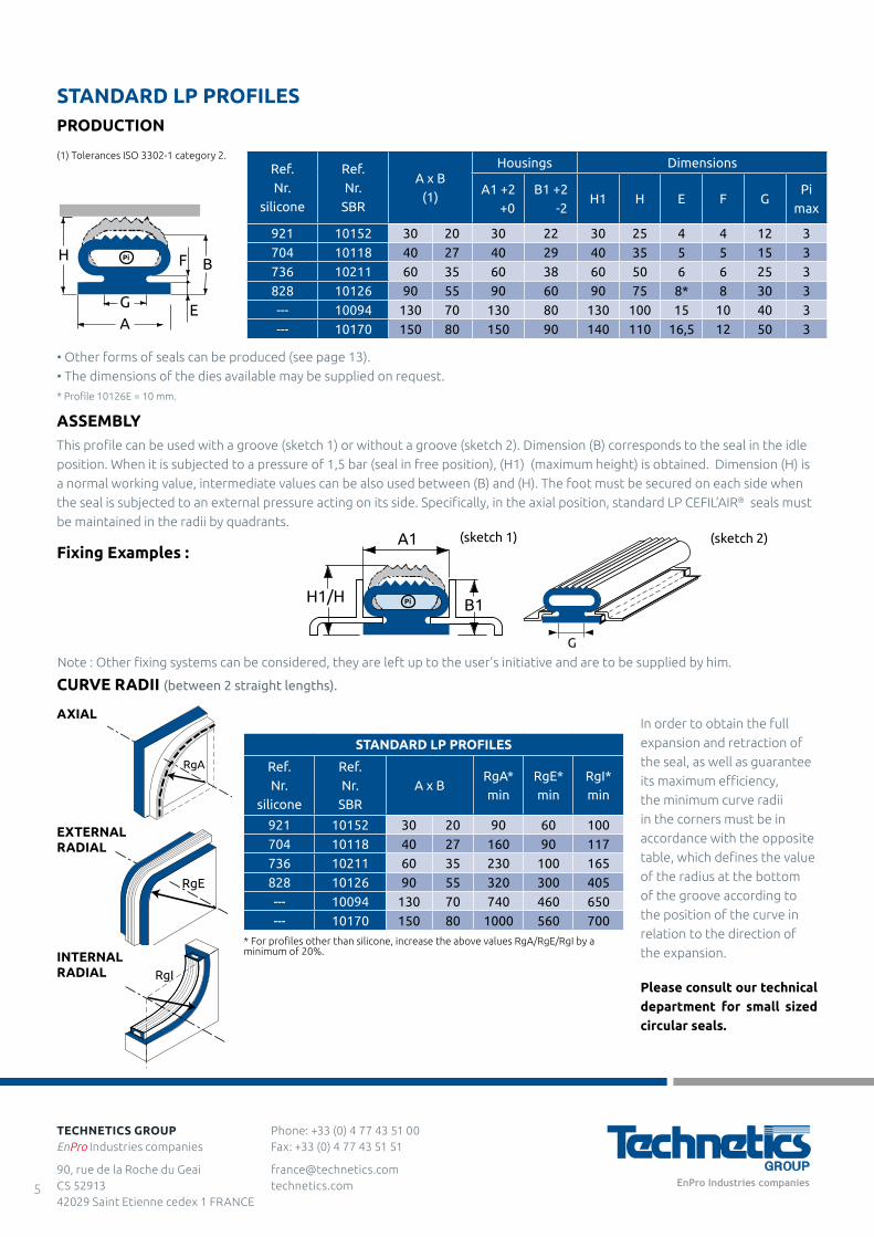
In order to obtain the full
expansion and retraction of
the seal, as well as guarantee
its maximum efficiency,
the minimum curve radii
in the corners must be in
accordance with the opposite
table, which defines the value
of the radius at the bottom
of the groove according to
the position of the curve in
relation to the direction of
the expansion.
Please consult our technical department for small sized circular seals.
STANDARD LP PROFILESPRODUCTION
(1) Tolerances ISO 3302-1 category 2.Ref.Nr.
silicone
Ref.Nr.
SBR
A x B(1)
Housings Dimensions
A1 +2 +0
B1 +2 -2
H1 H E F GPi
max
921 10152 30 20 30 22 30 25 4 4 12 3
704 10118 40 27 40 29 40 35 5 5 15 3
736 10211 60 35 60 38 60 50 6 6 25 3
828 10126 90 55 90 60 90 75 8* 8 30 3
--- 10094 130 70 130 80 130 100 15 10 40 3
--- 10170 150 80 150 90 140 110 16,5 12 50 3
STANDARD LP PROFILES
Ref.Nr.
silicone
Ref.Nr.
SBRA x B
RgA*min
RgE*min
RgI*min
921 10152 30 20 90 60 100
704 10118 40 27 160 90 117
736 10211 60 35 230 100 165
828 10126 90 55 320 300 405
--- 10094 130 70 740 460 650
--- 10170 150 80 1000 560 700
H
GA
E
F B
B1
A1
H1/H
G
RgA
RgE
RgI
CURVE RADII (between 2 straight lengths).
INTERNALRADIAL
EXTERNALRADIAL
AXIAL
• Other forms of seals can be produced (see page 13).
• The dimensions of the dies available may be supplied on request.
* Profile 10126E = 10 mm.
Note : Other fixing systems can be considered, they are left up to the user’s initiative and are to be supplied by him.
ASSEMBLYThis profile can be used with a groove (sketch 1) or without a groove (sketch 2). Dimension (B) corresponds to the seal in the idle
position. When it is subjected to a pressure of 1,5 bar (seal in free position), (H1) (maximum height) is obtained. Dimension (H) is
a normal working value, intermediate values can be also used between (B) and (H). The foot must be secured on each side when
the seal is subjected to an external pressure acting on its side. Specifically, in the axial position, standard LP CEFIL’AIR® seals must
be maintained in the radii by quadrants.
Fixing Examples :(sketch 1) (sketch 2)
Pi
Pi
* For profiles other than silicone, increase the above values RgA/RgE/RgI by a minimum of 20%.
Phone: +33 (0) 4 77 43 51 00 Fax: +33 (0) 4 77 43 51 51
[email protected] technetics.com
TECHNETICS GROUPEnPro Industries companies
90, rue de la Roche du Geai CS 52913 42029 Saint Etienne cedex 1 FRANCE
5
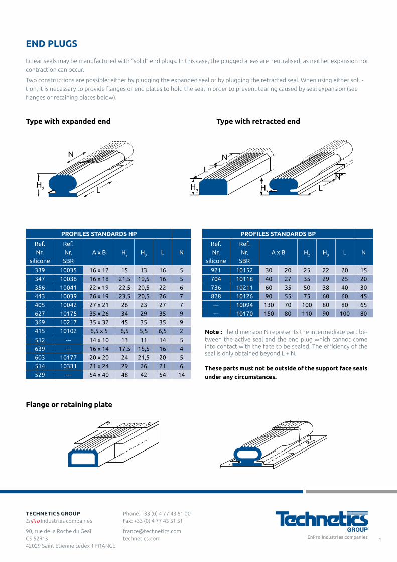
Note : The dimension N represents the intermediate part be-tween the active seal and the end plug which cannot come into contact with the face to be sealed. The efficiency of the seal is only obtained beyond L + N.
Type with retracted end
Flange or retaining plate
Type with expanded end
PROFILES STANDARDS HP
Ref.Nr.
silicone
Ref.Nr.
SBRA x B H2 H3 L N
339 10035 16 x 12 15 13 16 5
347 10036 16 x 18 21,5 19,5 16 5
356 10041 22 x 19 22,5 20,5 22 6
443 10039 26 x 19 23,5 20,5 26 7
405 10042 27 x 21 26 23 27 7
627 10175 35 x 26 34 29 35 9
369 10217 35 x 32 45 35 35 9
415 10102 6,5 x 5 6,5 5,5 6,5 2
512 --- 14 x 10 13 11 14 5
639 --- 16 x 14 17,5 15,5 16 4
603 10177 20 x 20 24 21,5 20 5
514 10331 21 x 24 29 26 21 6
529 --- 54 x 40 48 42 54 14
PROFILES STANDARDS BP
Ref.Nr.
silicone
Ref.Nr.
SBRA x B H2 H3 L N
921 10152 30 20 25 22 20 15
704 10118 40 27 35 29 25 20
736 10211 60 35 50 38 40 30
828 10126 90 55 75 60 60 45
--- 10094 130 70 100 80 80 65
--- 10170 150 80 110 90 100 80
N
LH2
N
NH3 H3
L
L
END PLUGS
Linear seals may be manufactured with “solid” end plugs. In this case, the plugged areas are neutralised, as neither expansion nor
contraction can occur.
Two constructions are possible: either by plugging the expanded seal or by plugging the retracted seal. When using either solu-
tion, it is necessary to provide flanges or end plates to hold the seal in order to prevent tearing caused by seal expansion (see
flanges or retaining plates below).
These parts must not be outside of the support face seals under any circumstances.
Phone: +33 (0) 4 77 43 51 00 Fax: +33 (0) 4 77 43 51 51
[email protected] technetics.com
TECHNETICS GROUPEnPro Industries companies
90, rue de la Roche du Geai CS 52913 42029 Saint Etienne cedex 1 FRANCE
6
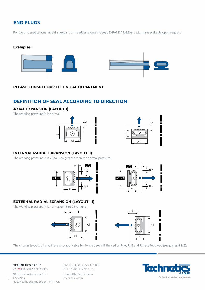
DEFINITION OF SEAL ACCORDING TO DIRECTION
Examples :
PLEASE CONSULT OUR TECHNICAL DEPARTMENT
AXIAL EXPANSION (LAYOUT I)The working pressure Pi is normal.
INTERNAL RADIAL EXPANSION (LAYOUT II)The working pressure Pi is 20 to 30% greater than the normal pressure.
EXTERNAL RADIAL EXPANSION (LAYOUT III)The working pressure Pi is normal or 15 to 25% higher.
A1
J
PiB1
JB1
A1
Pi
A1
J
B1
Pi A1
J
B1
Pi
A1 + 1
J/2
0,5
0,5B1
Pi A1 + 1
J/20,5
0,5B1
Pi
END PLUGS
For specific applications requiring expansion nearly all along the seal, EXPANDABALE end plugs are available upon request.
The circular layouts I, II and III are also applicable for formed seals if the radius RgA, RgE and RgI are followed (see pages 4 & 5).
Phone: +33 (0) 4 77 43 51 00 Fax: +33 (0) 4 77 43 51 51
[email protected] technetics.com
TECHNETICS GROUPEnPro Industries companies
90, rue de la Roche du Geai CS 52913 42029 Saint Etienne cedex 1 FRANCE
7
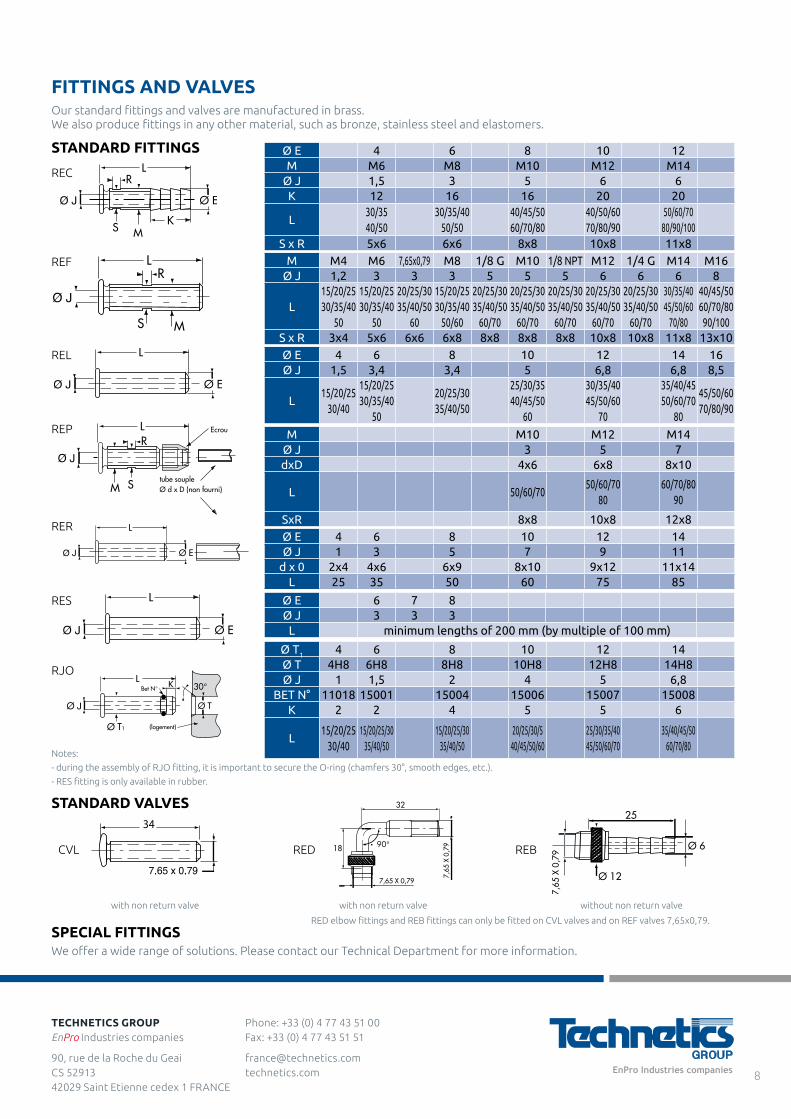
Notes:
- during the assembly of RJO fitting, it is important to secure the O-ring (chamfers 30°, smooth edges, etc.).
- RES fitting is only available in rubber.
SPECIAL FITTINGSWe offer a wide range of solutions. Please contact our Technical Department for more information.
RED elbow fittings and REB fittings can only be fitted on CVL valves and on REF valves 7,65x0,79.
FITTINGS AND VALVES
STANDARD FITTINGS
STANDARD VALVES
Ø E 4 6 8 10 12M M6 M8 M10 M12 M14
Ø J 1,5 3 5 6 6K 12 16 16 20 20
L30/3540/50
30/35/4050/50
40/45/5060/70/80
40/50/6070/80/90
50/60/7080/90/100
S x R 5x6 6x6 8x8 10x8 11x8M M4 M6 7,65x0,79 M8 1/8 G M10 1/8 NPT M12 1/4 G M14 M16
Ø J 1,2 3 3 3 5 5 5 6 6 6 8
L15/20/2530/35/40
50
15/20/2530/35/40
50
20/25/3035/40/50
60
15/20/2530/35/40
50/60
20/25/3035/40/50
60/70
20/25/3035/40/50
60/70
20/25/3035/40/50
60/70
20/25/3035/40/50
60/70
20/25/3035/40/50
60/70
30/35/4045/50/60
70/80
40/45/5060/70/80
90/100S x R 3x4 5x6 6x6 6x8 8x8 8x8 8x8 10x8 10x8 11x8 13x10Ø E 4 6 8 10 12 14 16Ø J 1,5 3,4 3,4 5 6,8 6,8 8,5
L15/20/25
30/40
15/20/2530/35/40
50
20/25/3035/40/50
25/30/3540/45/50
60
30/35/4045/50/60
70
35/40/4550/60/70
80
45/50/6070/80/90
M M10 M12 M14Ø J 3 5 7dxD 4x6 6x8 8x10
L 50/60/7050/60/70
8060/70/80
90
SxR 8x8 10x8 12x8
Ø T1 4 6 8 10 12 14Ø T 4H8 6H8 8H8 10H8 12H8 14H8Ø J 1 1,5 2 4 5 6,8
BET N° 11018 15001 15004 15006 15007 15008K 2 2 4 5 5 6
L15/20/25
30/4015/20/25/30
35/40/5015/20/25/30
35/40/5020/25/30/5
40/45/50/6025/30/35/4045/50/60/70
35/40/45/5060/70/80
REC
REF
REL
REP
RJO
Our standard fittings and valves are manufactured in brass.We also produce fittings in any other material, such as bronze, stainless steel and elastomers.
CVL RED REB
with non return valve with non return valve without non return valve
Ø E 4 6 8 10 12 14Ø J 1 3 5 7 9 11
d x 0 2x4 4x6 6x9 8x10 9x12 11x14L 25 35 50 60 75 85
RER
RES Ø E 6 7 8Ø J 3 3 3
L minimum lengths of 200 mm (by multiple of 100 mm)
Phone: +33 (0) 4 77 43 51 00 Fax: +33 (0) 4 77 43 51 51
[email protected] technetics.com
TECHNETICS GROUPEnPro Industries companies
90, rue de la Roche du Geai CS 52913 42029 Saint Etienne cedex 1 FRANCE
8
POSITION OF FITTINGS AND VALVES
CEFIL’AIR® inflatable seals conception requires that connections be located at the bottom of the grooves or at the
end of the seals (straight length). When seals have curves radii it is preferable to avoid connections located in the curved area.
If the equipment around the seal for assembly or other reasons requires a lateral supply, it is possible to use elbow fittings or
special constructions (please consult our technical department).
ASSEMBLY CONDITIONS
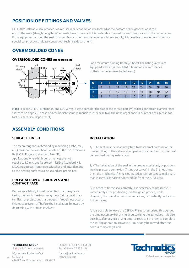
OVERMOULDED CONES
OVERMOULDED CONES (standard sizes)
hØ nØ mh+1
Ø+1
Housingdetail
Sealdetail
Ø Ø 4 4 6 8 10 12 14 16 18
m 6 8 12 14 21 24 26 28 30
n 5 6 10 12 14 16 18 20 22
h 3 4 6 6 10 10 12 12 12
Note : For REC, REF, REP fittings, and CVL valves, please consider the size of the thread part (M) as the connection diameter (see
sketches on page 7). In case of intermediate value (dimensions in inches), take the next larger cone. (For other sizes, please con-
tact our technical department).
For a maximum binding (metal/rubber), the fitting valves are
equipped with a overmoulded rubber cone in accordance
to their diameters (see table below).
SURFACE FINISH
The mean roughness obtained by machining (lathe, mill,
etc.) must not be less than the value of 0,8 to 1,6 microns
Ra (L.C.A. Rugotest, standard N6 - N7).
Applications where high performances are not
required, 3,2 microns Ra are permissible (standard N8,
L.C.A. Rugotest). Transverse scratches and local damage
to the bearing surfaces to be sealed are prohibited.
PREPARATION OF GROOVES AND CONTACT FACE
Before installation, it must be verified that the groove
taking the seal is free from roughness (grit or weld spat-
ter, flash or projections sharp edges). If roughness occurs,
this must be taken off before the installation, followed by
degreasing with a suitable solvent.
INSTALLATION
1/ - The seal must be absolutely free from internal pressure at the
time of fitting. If the valve is equipped with its mechanism, this must
be removed during installation.
2/ - The installation of the seal in the groove must start, by position-
ing the pressure connexion (fittings or valves) in the (in) housings,
then, the mechanical fixing is operated. It is important to make sure
that splice vulcanisation is located far from the curve area.
3/ In order to fit the seal correctly, it is necessary to pressurise it
immediately after positioning it in the glued groove, while
observing the operation recommendations, i.e. perfectly captive on
its four faces.
4/ It is possible to leave the CEFIL’AIR® seal pressurised throughout
the time necessary for drying or vulcanizing the adhesives ; it is also
possible, after a short drying time, to retract it in order to complete
the setting operation. However, it must only be moved after the
bond is completely fixed.
Phone: +33 (0) 4 77 43 51 00 Fax: +33 (0) 4 77 43 51 51
[email protected] technetics.com
TECHNETICS GROUPEnPro Industries companies
90, rue de la Roche du Geai CS 52913 42029 Saint Etienne cedex 1 FRANCE
9
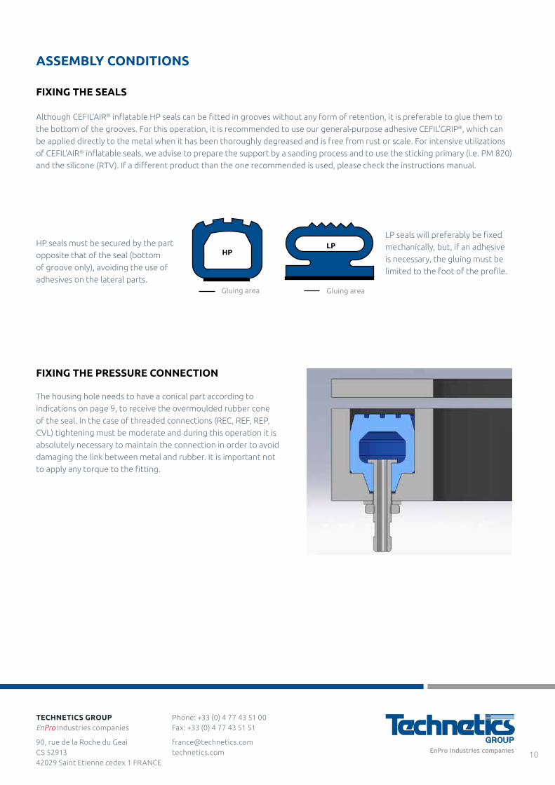
Gluing area Gluing area
HPLP
ASSEMBLY CONDITIONS
FIXING THE SEALS
Although CEFIL’AIR® inflatable HP seals can be fitted in grooves without any form of retention, it is preferable to glue them to
the bottom of the grooves. For this operation, it is recommended to use our general-purpose adhesive CEFIL’GRIP®, which can
be applied directly to the metal when it has been thoroughly degreased and is free from rust or scale. For intensive utilizations
of CEFIL’AIR® inflatable seals, we advise to prepare the support by a sanding process and to use the sticking primary (i.e. PM 820)
and the silicone (RTV). If a different product than the one recommended is used, please check the instructions manual.
HP seals must be secured by the part
opposite that of the seal (bottom
of groove only), avoiding the use of
adhesives on the lateral parts.
LP seals will preferably be fixed
mechanically, but, if an adhesive
is necessary, the gluing must be
limited to the foot of the profile.
FIXING THE PRESSURE CONNECTION
The housing hole needs to have a conical part according to
indications on page 9, to receive the overmoulded rubber cone
of the seal. In the case of threaded connections (REC, REF, REP,
CVL) tightening must be moderate and during this operation it is
absolutely necessary to maintain the connection in order to avoid
damaging the link between metal and rubber. It is important not
to apply any torque to the fitting.
Phone: +33 (0) 4 77 43 51 00 Fax: +33 (0) 4 77 43 51 51
[email protected] technetics.com
TECHNETICS GROUPEnPro Industries companies
90, rue de la Roche du Geai CS 52913 42029 Saint Etienne cedex 1 FRANCE
10
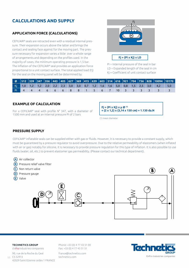
EXAMPLE OF CALCULATION
For a CEFIL’AIR® seal with profile N° 347, with a diameter of 1500 mm and used at an internal pressure Pi of 2 bars
A
B
C
D
E
Air collector
Pressure relief valve filter
Non return valve
Pressure gauge
Valve
Fj = (Pi x Kj) x LD
Fj = (Pi x Kj) x µ Ø (1)
= (2 x 1,2) x (3,14 x 150 cm) = 1.130 da.N
Ø 512 339 347 356 443 405 627 369 415 639 603 514 616 921 704 736 828 10094 10170
Kj 1,0 1,2 1,2 2,0 2,2 2,3 3,0 3,0 0,7 1,2 1,6 1,6 5,0 0,8 1,5 2,5 3,0 4,2 5,0
Pi 4 4 4 6 6 6 8 8 1 5 6 7 10 3 3 3 3 3 3
CD
E
AB
PRESSURE SUPPLY
CEFIL’AIR® inflatable seals can be supplied either with gas or fluids. However, it is necessary to provide a constant supply, which
must be guaranteed by a pressure regulator to avoid overpressure. Due to the relative permeability of elastomers (when inflated
with air or gas) notably for silicone, it is necessary to provide pressure regulation for this type of inflation. It is also possible to use
fluids (water, oil, etc.) to prevent elastomer gas permeability. (Please contact our technical department).
Pi = Internal pressure of the seal in bar
LD = Expanded length of the seal in cm
Kj = Coefficient of unit contact surface
CALCULATIONS AND SUPPLY
APPLICATION FORCE (CALCULATIONS)
CEFIL’AIR® seals are retracted even with a residual internal pres-
sure. Their expansion occurs above the latter and brings the
contact and sealing face against for the moving part. The pres-
sure necessary for expansion varies a little over a whole range
of arrangements and depending on the profiles used. In the
majority of cases, the minimum operating pressure is 1,5 bar. The inflation of the CEFIL’AIR® seal provides an application force
proportional to a unit contact surface. The total applied load (Fj)
for the seal on the moving panel will be determined by:
(1) mean diameter
Phone: +33 (0) 4 77 43 51 00 Fax: +33 (0) 4 77 43 51 51
[email protected] technetics.com
TECHNETICS GROUPEnPro Industries companies
90, rue de la Roche du Geai CS 52913 42029 Saint Etienne cedex 1 FRANCE
11
Fj
Pi
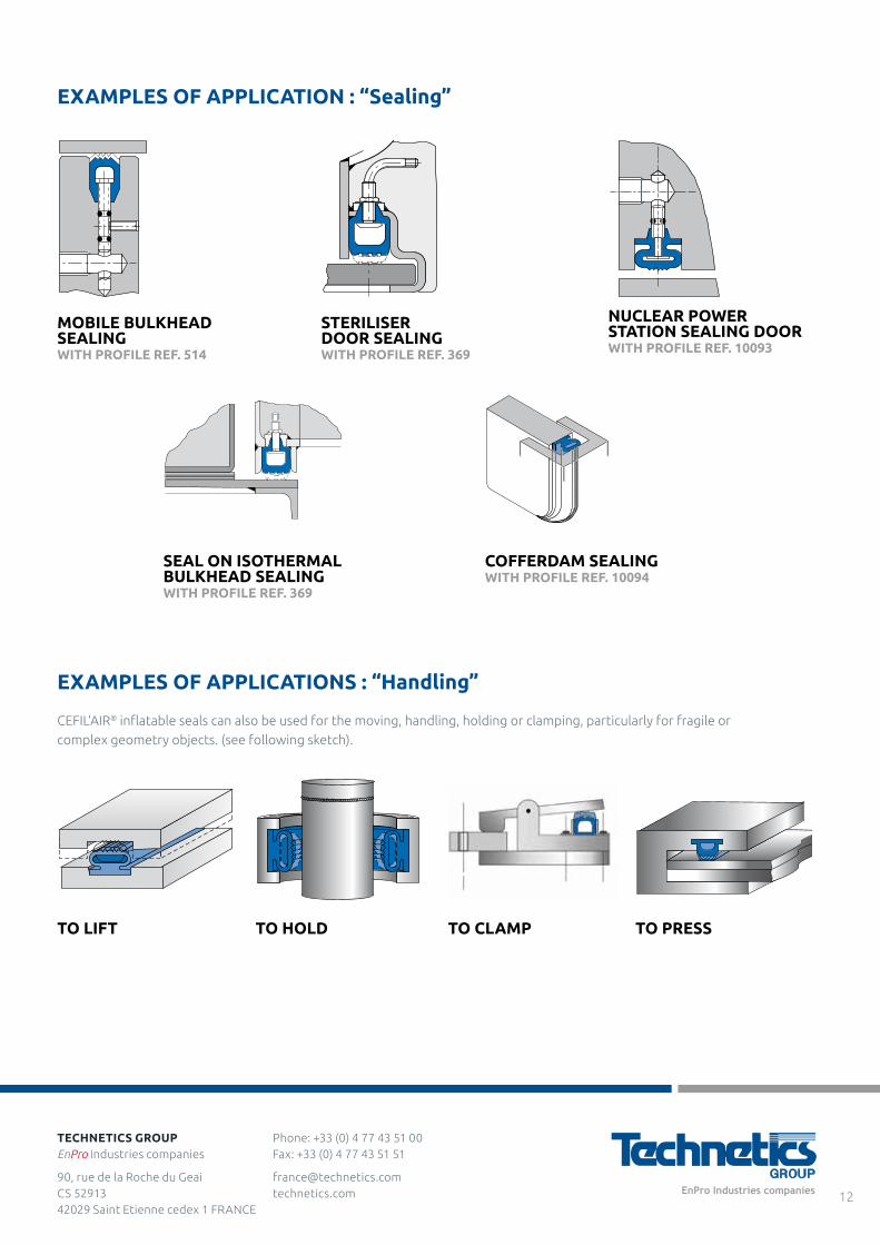
EXAMPLES OF APPLICATION : “Sealing”
MOBILE BULKHEAD SEALING WITH PROFILE REF. 514
SEAL ON ISOTHERMAL BULKHEAD SEALING WITH PROFILE REF. 369
COFFERDAM SEALING WITH PROFILE REF. 10094
STERILISER DOOR SEALING WITH PROFILE REF. 369
NUCLEAR POWER STATION SEALING DOOR WITH PROFILE REF. 10093
EXAMPLES OF APPLICATIONS : “Handling”
CEFIL’AIR® inflatable seals can also be used for the moving, handling, holding or clamping, particularly for fragile or
complex geometry objects. (see following sketch).
TO LIFT TO PRESSTO HOLD TO CLAMP
Phone: +33 (0) 4 77 43 51 00 Fax: +33 (0) 4 77 43 51 51
[email protected] technetics.com
TECHNETICS GROUPEnPro Industries companies
90, rue de la Roche du Geai CS 52913 42029 Saint Etienne cedex 1 FRANCE
12
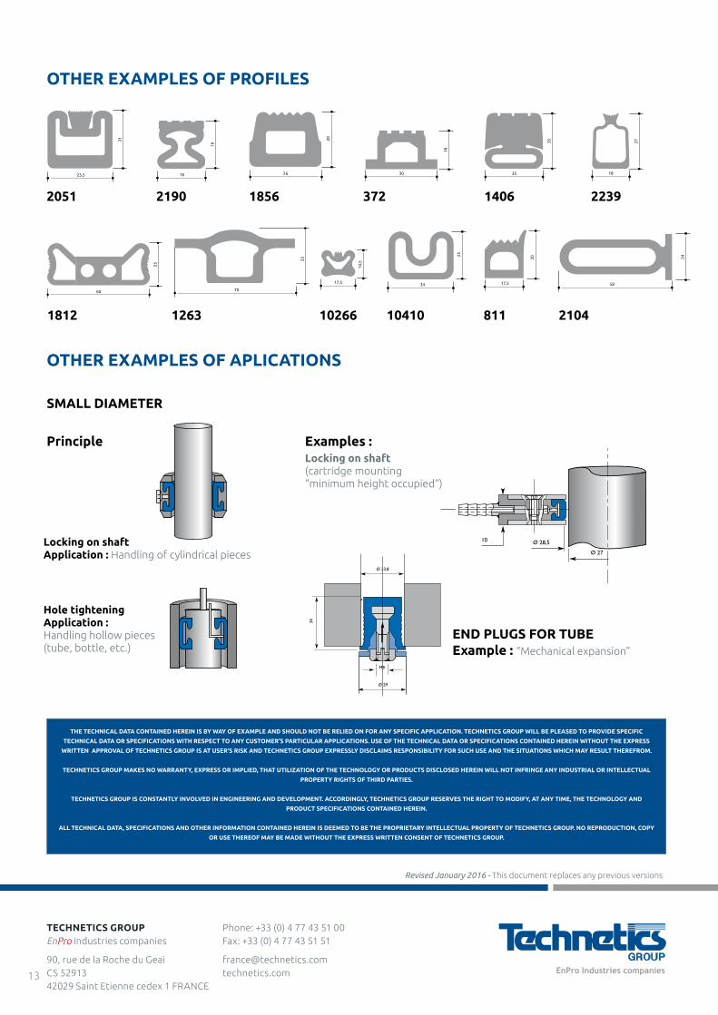
OTHER EXAMPLES OF PROFILES
2051 3722190 14061856 2239
21
23,5
18
30
35
35
27
18
16
16
20
26
25
60
33
70
17,5
14,5
17,5
20
34
25
24
58
OTHER EXAMPLES OF APLICATIONS
SMALL DIAMETER
Principle
END PLUGS FOR TUBEExample : “Mechanical expansion”
Locking on shaftApplication : Handling of cylindrical pieces
Ø 28,510
Ø 27
Ø 23,8
Ø 29
M8
34
Ø 28,510
Ø 27
Ø 23,8
Ø 29
M8
34
Examples :Locking on shaft (cartridge mounting“minimum height occupied“)
Hole tighteningApplication : Handling hollow pieces(tube, bottle, etc.)
Ø 28,510
Ø 27
Ø 23,8
Ø 29
M8
34
Ø 28,510
Ø 27
Ø 23,8
Ø 29
M8
34
THE TECHNICAL DATA CONTAINED HEREIN IS BY WAY OF EXAMPLE AND SHOULD NOT BE RELIED ON FOR ANY SPECIFIC APPLICATION. TECHNETICS GROUP WILL BE PLEASED TO PROVIDE SPECIFIC
TECHNICAL DATA OR SPECIFICATIONS WITH RESPECT TO ANY CUSTOMER’S PARTICULAR APPLICATIONS. USE OF THE TECHNICAL DATA OR SPECIFICATIONS CONTAINED HEREIN WITHOUT THE EXPRESS
WRITTEN APPROVAL OF TECHNETICS GROUP IS AT USER’S RISK AND TECHNETICS GROUP EXPRESSLY DISCLAIMS RESPONSIBILITY FOR SUCH USE AND THE SITUATIONS WHICH MAY RESULT THEREFROM.
TECHNETICS GROUP MAKES NO WARRANTY, EXPRESS OR IMPLIED, THAT UTILIZATION OF THE TECHNOLOGY OR PRODUCTS DISCLOSED HEREIN WILL NOT INFRINGE ANY INDUSTRIAL OR INTELLECTUAL
PROPERTY RIGHTS OF THIRD PARTIES.
TECHNETICS GROUP IS CONSTANTLY INVOLVED IN ENGINEERING AND DEVELOPMENT. ACCORDINGLY, TECHNETICS GROUP RESERVES THE RIGHT TO MODIFY, AT ANY TIME, THE TECHNOLOGY AND
PRODUCT SPECIFICATIONS CONTAINED HEREIN.
ALL TECHNICAL DATA, SPECIFICATIONS AND OTHER INFORMATION CONTAINED HEREIN IS DEEMED TO BE THE PROPRIETARY INTELLECTUAL PROPERTY OF TECHNETICS GROUP. NO REPRODUCTION, COPY
OR USE THEREOF MAY BE MADE WITHOUT THE EXPRESS WRITTEN CONSENT OF TECHNETICS GROUP.
Revised January 2016 - This document replaces any previous versions
1812 1263 10266 10410 811 2104
Phone: +33 (0) 4 77 43 51 00 Fax: +33 (0) 4 77 43 51 51
[email protected] technetics.com
TECHNETICS GROUPEnPro Industries companies
90, rue de la Roche du Geai CS 52913 42029 Saint Etienne cedex 1 FRANCE
13
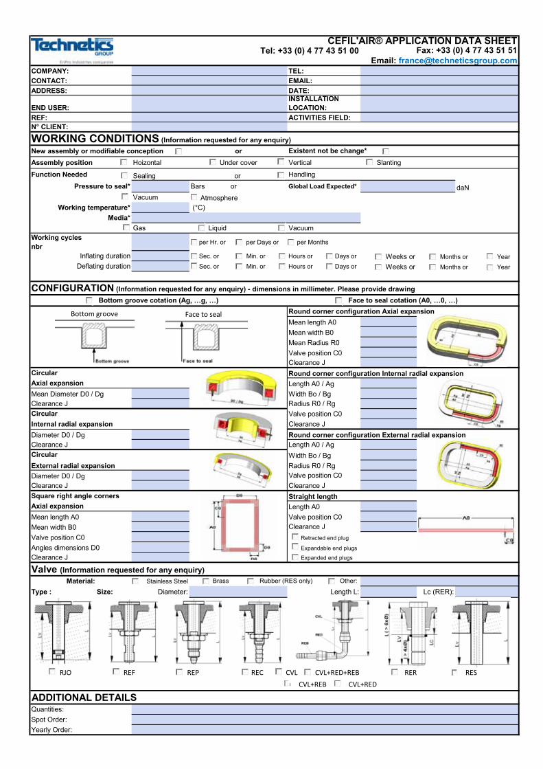
COMPANY: TEL:CONTACT: EMAIL:ADDRESS: DATE:
END USER:INSTALLATION LOCATION:
REF: ACTIVITIES FIELD:N° CLIENT:
New assembly or modifiable conception orAssembly position Hoizontal Under cover Vertical Slanting
Function Needed Sealing or Handling
Pressure to seal* Bars or Global Load Expected* daNVacuum Atmosphere
Working temperature* (°C)Media*
Gas Liquid VacuumWorking cycles nbr per Hr. or per Days or per Months
Inflating duration Sec. or Min. or Hours or Days or Weeks orDeflating duration Sec. or Min. or Hours or Days or Weeks or
Round corner configuration Axial expansionMean length A0Mean width B0Mean Radius R0Valve position C0Clearance J
Circular Round corner configuration Internal radial expansionAxial expansion Length A0 / AgMean Diameter D0 / Dg Width Bo / BgClearance J Radius R0 / Rg
Valve position C0Internal radial expansion Clearance JDiameter D0 / Dg Round corner configuration External radial expansionClearance J Length A0 / Ag
Width Bo / BgExternal radial expansion Radius R0 / RgDiameter D0 / Dg Valve position C0Clearance J Clearance JSquare right angle corners Straight lengthAxial expansion Length A0Mean length A0 Valve position C0Mean width B0 Clearance JValve position C0 Retracted end plug
Angles dimensions D0 Expandable end plugs
Clearance J Expanded end plugs
Valve (Information requested for any enquiry)Material: Stainless Steel
Type : Size: Diameter: Length L: Lc (RER):
CVL+REB CVL+RED
ADDITIONAL DETAILSQuantities: Spot Order:Yearly Order:
Circular
Circular
Brass Rubber (RES only) Other:
Bottom groove cotation (Ag, …g, …) Face to seal cotation (A0, …0, …)
WORKING CONDITIONS (Information requested for any enquiry)Existent not be change*
Months or Year Months or Year
CONFIGURATION (Information requested for any enquiry) - dimensions in millimeter. Please provide drawing
CEFIL'AIR® APPLICATION DATA SHEETTel: +33 (0) 4 77 43 51 00 Fax: +33 (0) 4 77 43 51 51
Email: [email protected]
RJO REF REP REC CVL CVL+RED+REB RER RES
Bottom groove Face to seal
C

TECHNETICS GROUPEnPro Industries companies
[email protected] technetics.com
For more information on how Technetics Group affects your critical markets, visit technetics.com.
ASIA
Blk 203, #05-52 Woodlands Avenue 9 Woodlands Spectrum 2, 738956 Singapore
Phone: +65 6759 2335 Fax: +65 6759 7319
FRANCE
90, rue de la Roche du Geai CS 52913 42029 Saint Etienne cedex 1 FRANCE
Phone: +33 (0) 4 77 43 51 00 Fax: +33 (0) 4 77 43 51 51
49 Avenue Charles de Gaulle Z.I. Survaure 42607 Montbrison cedex FRANCE
Phone: +33 (0) 4 77 96 79 80
GERMANY
Falkenweg 1 41468 Neuss Germany
Phone: 0800-627-0151
UK
Acan Way, Coventry Road Narborough, Leicester LE19 2FT UK
Phone: +44 (0) 1162 727411 Fax: +44 (0) 1162 727412
USA
2791 The Boulevard Columbia, SC 29209 USA
Phone: +1-803-783-1880 Fax: +1-803-783-4279
305 Fentress Boulevard Daytona Beach, FL 32114 USA
Phone: +1-386-253-0628 Fax: +1-386-257-0122
1700 E. International Speedway Blvd DeLand, FL 32724 USA
Phone: +1-386-736-7373 Fax: +1-386-738-4533
1600 Industry Road Hatfield, PA 19440 USA
Phone: +1-800-618-4701 Fax: +1-215-855-3570
10633 W Little York, Bldg 3, Suite 300 Houston, TX 77041 USA
Phone: +1-713-983-4201 Fax: +1-713-466-3721
10 Old Webster Road Oxford, MA 01540 USA
Phone: +1-508-987-5900
990 Richard Avenue, Suite 117 Santa Clara, CA 95050 USA
Phone: +1-669-242-8804 Fax: +1-669-242-8492