ceilair cw and dx - stulz usa...tion of the system at a 95 °f db ambient temperature. the system...
TRANSCRIPT

CeilAir® CW and DXEngineering ManualCeiling Mounted Precision Air Conditioners/Air Handlers3.5-35 kW / 60 Hz

iii
CeilAiR ENGINEERING MANUAL
Notice
This document contains information protected by copyright. All rights are reserved. The owner of the equipment for which this manual is written may photocopy the contents of this manual for internal use only. No part of this document may be photocopied, reproduced, or translated into another language for use by anyone other than the owner of the equipment for which this manual is written without the prior written consent of STULZ Air Technology Systems, Inc. (STULZ). This document contains confidential and proprietary information of STULZ Air Technology Systems, Inc. Distributing or photo- copying this document for external distribution is in direct violation of U.S. copyright laws and is strictly prohibited without the express written consent of STULZ. Unpublished — rights reserved under the copyright laws of the United States and of other countries. Other brands and tradenames are trademarks of their respective owners. Copyright 2018 by STULZ Air Technology Systems, Inc. Printed in the United States of America. All rights reserved. STULZ Air Technology Systems, Inc. 1572 Tilco Drive Frederick, MD 21704 USA https://www.stulz-usa.com/en/

iii
CeilAiR ENGINEERING MANUAL
Table of Contents
Model Nomenclature Guide Specifications ............ 1 DX Models ............................................................................................. 1
Air-Cooled, Self-Contained: Integral Self-Contained (Models OHS-012/040-AS) ...................................................... 1 DX - Evaporator Sections: Air Cooled Remote Evaporator (Models OHS-( )-()AR) ................................................................... 1 DX - Water Cooled Systems: Integral Self-Contained Models OHS-( )-W / DW .............................................................. 1
Chilled Water Air Handlers ............................................................... 1 Chilled Water System (Models OHS-( )-C). ............................. 1
CeilAiR Models ........................................................ 2 Selected Standard Features ........................................................... 4 Specific Model Standard Features ............................................... 4
Technical Specifications and Performance/ Capacity Data .......................................................... 5
Direct Expansion Air/Water/Glycol-Cooled Models .......... 6 DX - Self-Contained Air Cooled (AS) 3.5 – 10.5 kW / Split Air Cooled (AR) Technical Data, 3.5–17.5 kW ....... 6 DX Dual Compressor- Split Air Cooled Remote w/ Condenser Technical Data, 14–35 kW .............................. 7 DX Dual Compressor- Split Air Cooled Remote w/ Condenser Technical Data, 14−35 kW (Cont) ................. 8
DX - Split Air Cooled w/Condensing Unit Technical Data, 3.5−17.5 kW .................................................................. 9 DX Dual Compressor - Split Air Cooled w/Condensing Unit Technical Data, 14−35 kW .........................................10 DX- Self-Contained Water Cooled Technical Data, 3.5−17.5 kW ............................................................................11 DX Dual Compressor - Self-Contained Water Cooled Technical Data, 14−35 kW ..................................................12 DX - Self-Contained Glycol Cooled Technical Data, 3.5−17.5 kW ............................................................................13 DX Dual Compressor - Self-Contained Glycol Cooled Technical Data, 14−35 kW ..................................................14 DX - Self-Contained Air Cooled (AS) 3.5 - 10.5 kW / Split Air Cooled Cooling Capacities, 3.5–17.5 kW ......15 DX Dual Compressor- Split Air Cooled Remote w/ Condenser Cooling Capacities, 14−35 kW ...................15 DX - Split Air Cooled w/Condensing Unit Cooling Capacities, 3.5−17.5 kW .....................................................16 DX Dual Compressor - Split Air Cooled w/Condensing Unit Cooling Capacities, 14−35 kW .................................16 DX- Self-Contained Water Cooled Cooling Capacities, 3.5−17.5 kW ............................................................................17 DX Dual Compressor - Self-Contained Water Cooled Cooling Capacities, 14−35 kW ..........................................17
DX - Self-Contained Glycol Cooled Cooling Capacities, 3.5−17.5 kW ............................................................................ 18 DX Dual Compressor - Self-Contained Glycol Cooled Cooling Capacities, 14−35 kW .......................................... 18
DX Free Cooling/Alternate Water Source .......................... 19 DX with Free Cooling - Self-Contained Water Cooled Technical Data, 3.5−17.5 kW ............................................. 19 DX Dual Compressor with Free Cooling - Self-Contained Water Cooled Technical Data, 14−35 kW ...................... 20 DX with Free Cooling- Self-Contained Glycol Cooled Technical Data, 3.5−17.5 kW ............................................. 21 DX Dual Compressor with Free Cooling - Self-Contained Glycol Cooled Technical Data, 14−35 kW ...................... 22 DX with Alternate Water Source Technical Data, 3.5−17.5 kW ............................................................................ 23 DX with Alternate Water Source, 14−35 kW ................. 23
DX with Free Cooling - Self-Contained Water Cooled Cooling Capacities, 3.5−17.5 kW ..................................... 24 DX Dual Compressor with Free Cooling - Self-Contained Water Cooled Cooling Capacities, 14−35 kW .............. 25 DX with Free Cooling - Self-Contained Glycol Cooling Capacities, 3.5−17.5 kW ..................................................... 26 DX Dual Compressor with Free Cooling - Self-Contained Glycol Cooling Capacities, 14−35 kW ............................. 27 DX with Alternate Water Source Cooling Capacities, 3.5−17.5 kW ............................................................................ 28 DX with Alternate Water Source Cooling Capacities, 14−35 kW................................................................................. 29 Alternate Water Source 42 °F EWT Cooling Capacities ................................................................................... 30 Alternate Water Source 42 °F EWT Cooling Capacities ................................................................................... 31 Alternate Water Source 50 °F EWT Cooling Capacities ................................................................................... 32 Alternate Water Source 50 °F EWT Cooling Capacities ................................................................................... 33
Chilled Water Models ............................................................... 34
Chilled Water Air Handler Technical Data, 3.5−10.5 kW ............................................................................ 34 Chilled Water Air Handler Technical Data, 14−35 kW................................................................................. 35 Chilled Water Air Handler Cooling Capacities, 3.5−12 kW................................................................................ 36 Chilled Water Air Handler Cooling Capacities, 3.5−12 kW (Con’t) .................................................................. 37 Chilled Water Air Handler Cooling Capacities, 14−35 kW................................................................................. 38 Chilled Water Air Handler Cooling Capacities, 14−35 kW (Con’t) ................................................................... 39 Chilled Water 42 °F EWT Cooling Capacities ................. 40 Chilled Water 42 °F EWT Cooling Capacities ................. 41
Table Of C
ontents

iv
CeilAiR ENGINEERING MANUAL
Chilled Water 50 °F EWT Cooling Capacities ................. 42 Chilled Water 50 °F EWT Cooling Capacities ................. 43
Electrical Data (FLA / MCA / MFS) ........................ 43 DX Air, Water, and Glycol Cooled ............................................. 45
With Condensate Pump (OHS-012 − OHS-060 AS)............................................................................ 45 Without Condensate Pump (OHS-012 − OHS-060 AS)............................................................................ 45 With Condensate Pump (OHS-012 − OHS-024 / AR, W, G) ............................................................. 45 Without Condensate Pump (OHS-012 − OHS-024 / AR, W, G) ..................................................................................... 46 With Condensate Pump (OHS-032 − OHS-060 / AR, W, G) ............................................................................................. 46 Without Condensate Pump (OHS-032 − OHS-060 / AR, W, G) ..................................................................................... 47 With Condensate Pump (OHS-048 − OHS-120 DAR, DW, DG) ....................................................................................... 48 Without Condensate Pump (OHS-048 − OHS-120 DAR, DW, DG)............................................................................ 47
With Condensate Pump (OHS-012 − OHS-032 AHU) ............................................................................................. 49 Without Condensate Pump (OHS-012 − OHS-032 AHU) ............................................................................................. 49
With Condensate Pump (OHS-040 − OHS-060 AHU) ........................................................................ 50 Without Condensate Pump (OHS-040 − OHS-060 AHU) ............................................................................................. 49 With Condensate Pump (OHS-048 − OHS-120 DAHU) ......................................................................................... 51 Without Condensate Pump (OHS-048 − OHS-120 DAHU) ......................................................................................... 51
DX Free Cooling and Alternate Water Source .................... 51 With Condensate Pump (OHS-012 − OHS-024 HAR, HW, HG) ...................................................................................... 51 Without Condensate Pump (OHS-012 − OHS-024 HAR, HW, HG) ........................................................................... 51 With Condensate Pump (OHS-032 − OHS-060 HAR, HW, HG) ...................................................................................... 52 Without Condensate Pump (OHS-032 − OHS-060 HAR, HW, HG) ........................................................................... 52 With Condensate Pump (OHS-048 − OHS-120 DAR, DW, DG) ....................................................................................... 53 Without Condensate Pump (OHS-048 − OHS-120 DAR, DW, DG)............................................................................ 53
Chilled Water ................................................................................. 54 With Condensate Pump (OHS-012 − OHS-040 C) ... 54
Without Condensate Pump (OHS-012 − OHS-040 C) .............................................................................. 54
With Condensate Pump (OHS-048 − OHS-120 C) .............................................................................. 55 Without Condensate Pump (OHS-048 − OHS-120 C) .............................................................................. 55
Dimensional Data and Installation Drawings ........ 57 Physical Data and Connection Sizes ...................................... 58 Air Cooled Systems ...................................................................... 60 DX Air Handling Units .................................................................. 64 Water/Glycol Systems ................................................................ 66 Chilled Water Systems ................................................................ 70
CeilAiR Product Guide Specifications ................... 72 SUMMARY .......................................................................................... 72 Design Requirements ...................................................................... 72 Quality Assurance ............................................................................. 72
Cabinet ................................................................................................. 72 Air Flow Patterns ............................................................................... 72
“Ductless” Spot Cooler (Models OHS-012 thru 040-( ) only) ........................................................................... 72 Ducted Evaporator (Available on all model sizes) ............... 72
Air Filtration ......................................................................................... 72 Mechanical Components ................................................................ 72
Blowers/Motors ................................................................................ 72 Direct Drive Systems ................................................................... 72 Belt Driven Systems .................................................................... 72
Refrigeration System ....................................................................... 72 Scroll Compressor ........................................................................ 72 Evaporator Coil. ............................................................................. 73
Air Cooled Heat Rejection ......................................................... 73 Water Cooled Heat Rejection ....................................................... 73
Chilled Water System .................................................................. 73 Chilled Water Control Valve ......................................................... 73
Overflow Safety Float Switch ........................................................ 73 Remote Start/Stop .......................................................................... 73
Electrical System .............................................................................. 73 A-Tech-1.1 Controller ...................................................................... 74 E2 Series Controller .............................................................................. 74
Field Configurable ........................................................................ 74 Password Protection ....................................................................... 74
Restorable Parameters/Factory Defaults ........................... 74
Timer Feature ................................................................................ 74 A/C Grouping pLAN Operation ............................................... 74
Remote BMS ...................................................................................... 75 Alarms .............................................................................................. 75 E2 Constant Contact .................................................................... 75

v
CeilAiR ENGINEERING MANUAL
Full-Floating Hot Gas Bypass .................................................. 75 Snap-acting Hot Gas Bypass ....................................................... 75
High-Static Pressure Belt Drive Blowers .............................. 75
Low Entering Condenser Water Kit ....................................... 75 Steam-Generating Humidifier...................................................... 75
Dehumidification Cycle .............................................................. 75 Electric Reheat/Heat...................................................................... 76
Hot Gas Reheat ............................................................................ 76 Hot Water Reheat/Heat ............................................................ 76 SCR Fired Reheat/Heat (Requires E²controller) .............. 76 Low Profile Condensate Pump ................................................ 76 All-Metal Condensate Pump (optional). ................................ 76
Dual Overflow Safety Switches ............................................... 76 Air Filtration ........................................................................................ 76
Smoke Detector ........................................................................... 76 Firestat ............................................................................................ 76 Water Detectors ........................................................................... 77 Compressor Sound Jacket ....................................................... 77
Electrical Options ......................................................................... 77 Three Phase Power Supply ...................................................... 77 277/1/60 Power Supply ......................................................... 77 Main Power - Electric Non-Fused Service Switch ............ 77 Controller Options ........................................................................ 77
A-Tech-1.2 Controller ..................................................................... 77
Air-Side Economizer Controls ................................................. 78 Alternate Water Source ............................................................. 78
Code Conformance ......................................................................... 78

vi
CeilAiR ENGINEERING MANUAL
Nomenclature
OHS-XXX-XX-XX
System Nominal
Capacity in 1,000’s of
BTU/Hr
Configuration Options
OHS = CeilAiR Overhead System
012, 018, 024, 032, 040, 048, 060, 072, 084, 120
D( ) = Dual Circuit H( ) = Horizontal
Discharge (“H-Series”)
AHU = Air Handling Unit AR = Air-Cooled Remote (Split) AS = Air-Cooled Self-Contained C = Chilled Water System G = Glycol-Cooled W = Water Cooled
AWS = Alternate Water Source FC = Free Cooling LP = Low Profile Configuration SF = Same-Face Air Pattern SP = Special Configuration *
OHS 040 H G FC
* Call 888 529 1266 for additional information.
Example: OHS-040-HG-FC
Overhead System, 40,000 BTU/Hr Capacity, Horizontal Discharge, Glycol Cooled with optional Free Cooling: OHS-040-G-FC
STULZ Condensers and Condensing Units are documented in our Heat Rejection Engineering Manual.
STULZ Pump Packages and Drycoolers are documented in our Glycol Systems Engineering Manual.

1
CeilAiR ENGINEERING MANUAL
Model Nomenclature Guide Specifications DX Models Air-Cooled, Self-Contained: Integral Self- Contained (Models OHS-012/040-AS)
The system shall be a self-contained, ceiling mounted air con- ditioner with factory mounted integral air cooled condenser with centrifugal blower.
The condenser shall be sized to provide the total heat of rejec- tion of the system at a 95 °F DB ambient temperature.
The system shall require only single point supply power con- nection and the system shall ship from the STULZ factory with a full operating refrigerant charge.
DX - Evaporator Sections: Air Cooled Remote Evaporator (Models OHS-( )-()AR) The system shall be a remote (split) air cooled, ceiling mounted air conditioner evaporator. The evaporator section shall house, as a minimum, the evaporator coil, expansion valve, compressor, evaporator blower/motor and associated electrical and refrig- eration components.
The OHS-( )-()AR evaporator section shall be located at some distance from its corresponding CeilAiR model HES-( )-()CAA indoor or SCS-( ) outdoor air cooled condenser.
The evaporator system shall require only single point main power supply connection and the system shall ship from the STULZ factory with a dry nitrogen holding charge ready for field refrigerant (R-407C) charging. STULZ Condensers and Condensing Units are documented in the STULZ Heat Rejection Engineering Manual.
DX - Water Cooled Systems: Integral Self- Contained Models OHS-( )-W / DW The system shall be a self-contained, ceiling mounted air con- ditioner to include integral water cooled, coaxial condenser with head pressure water regulating control valve(s) (not applicable to OHS( ) ( ) G-W-FC models)*. Condenser (source) water shall be provided by cooling tower or some other remote water source.
The system shall require only single point supply power connec- tion and shall ship from the STULZ factory with a full operating refrigerant charge.
Water Regulating Valves Head pressure shall be automatically controlled by a factory installed 2-way water regulating valve rated for 150 psi wwp 3-way and high pressure 300 to 400 psi rated valves are available as options. See “Water and Glycol Regulating Control Valves” on page 74. * 2-way valves are factory installed; 3-way valves are field installed.
DX - Glycol-Cooled Systems: Integral Self-Contained (Models OHS-( )-G / DG) The system shall be a self-contained, ceiling mounted air conditioner to include integral glycol cooled, coaxial con- denser with factory installed head pressure glycol regulating control valve(s). Condenser (source) glycol solution shall be provided via a CeilAiR model GPS-( )-( ) / FSS/FDS remote glycol pump package and drycooler system.
The system shall require only single point supply power connection and shall ship from the STULZ factory with a full operating refrigerant charge.
Glycol Regulating Valves Head pressure shall be automatically controlled by a fac- tory-installed 2-way glycol regulating valve rated for 150 psi wwp 3-way and high pressure 300 to 450 psi rated valves are available as options. “Water and Glycol Regulating Control Valves” .
Chilled Water Air Handlers
Chilled Water System (Models OHS-( )-C) The system shall be a ceiling mounted chilled water air condi- tioner to include chilled water cooling coil, evaporator blower and motor and chilled water control valve. Chilled water shall be provided by a remote liquid chiller system.
Chilled Water Control Valve Cooling capacity shall be controlled with a slowly opening and slowly closing 2-way motorized control valve rated for 300 psi wwp 3-way 300 psi motorized valves and 2 or 3-way modulating valves are available as options (except on OHS-( )-( )-G-W-FC models). See “Chilled Water and AWS Control Valves” on page 75.

2
CeilAiR ENGINEERING MANUAL

3
CeilAiR ENGINEERING MANUAL

4
CeilAiR ENGINEERING MANUAL
OHS Model: 012/040-( ) 012/040-H( ) 048/060-( ) 048/120-D( )
SELECTED STANDARD FEATURES
TEMPERATURE CONTROL
Cooling Only Standard Standard Standard Standard Heating / Reheating Control Optional Optional Optional Optional
HUMIDITY CONTROL Electrode Canister Steam Humidifier Optional Optional Optional Optional Dehumidification Mode with Reheat Optional Optional Optional Optional
CONTROLS
A-Tech-1.1 single stage controls Standard Standard Standard N/A
A-Tech-1.2 two stage controls Optional Optional Optional Standard E² Microprocessor Controller Optional Optional Optional Optional
CABINET All Aluminum Construction Standard Standard Standard Standard Insulated SS or Polymer Condensate Drain Pan Standard Standard Standard Standard 1/2", 2 lb Density Thermal & Sound Insulation Standard Standard Standard Standard Rubber Hanging Vibration Isolators Standard Standard Standard Standard
FILTERS / GRILLES Spot Coolers with bottom supply / return filter grille Standard N/A N/A N/A Ducted Units with flanged ducted connections Optional Standard Standard Standard
DX-REFRIGERATION CIRCUIT R407C Refrigerant Standard Standard Standard Standard Scroll Type Compressor(s), (unless otherwise noted) Standard Standard Standard Standard High Efficiency, Aluminum Fin / Copper Tube Coils Standard Standard Standard Standard Thermal Expansion Valve Standard Standard Standard Standard Refrigerant Sight Glass & Filter/Drier Strainer Standard Standard Standard Standard Refrigerant Service Valves Standard Standard Standard Standard
BLOWERS / MOTORS Direct-Drive Evaporator Motors Standard N/A N/A N/A Belt-Drive Evaporator Motors N/A Standard Standard Standard
ELECTRICAL Power Supply ------------------------- See Electrical Tables ---------------------- Multi-Voltage Control Transformer (24V Class II) Standard Standard Standard Standard Individual Motor Starter(s) / Contactor(s) Standard Standard Standard Standard
SAFETY FEATURES Condensate Pan Overflow Safety Switch(es) Standard Standard Standard Standard High / Low Refrigerant Pressure Switches (DX units) Standard Standard Standard Standard Motor Overcurrent and Overload Protection Per UL 1995 Standard Standard Standard Standard
SPECIFIC MODEL STANDARD FEATURES
AIR COOLED
Low Ambient Head Pressure Control --------Three types available 0°F, -20°F or -30°F ---------
WATER / GLYCOL COOLED 2-way, 150 psig Water/Glycol Regulating Valves Standard Standard Standard Standard High Pressure & 3-way Valves Optional Optional Optional Optional Coaxial, Tube-in-Tube Heat Exchanger Standard Standard Standard Standard
ALL SPLIT DX SYSTEMS
Liquid Line Solenoid Valve to Prevent Liquid Slugging Standard Standard Standard Standard
DUAL CIRCUIT DX SYSTEMS Two(2) Independent Refrigerant Circuits N/A N/A N/A Standard Two(2) Equal Horsepower Scroll Compressors (1 per circuit) N/A N/A N/A Standard A-Tech-1.2 two stage controls N/A N/A N/A Standard
CHILLED WATER SYSTEMS 2-way, 300 psig Motorized Valve Standard Standard Standard Standard Modulating, High Pressure & 3-way Valves Optional Optional Optional Optional
CODE CONFORMANCE NRTL Conformance Compliance to UL 1995 Standard Standard Standard Standard Standard NYC MEA-163-88-E / Chicago Code Approval Standard Standard Standard Standard

5
CeilAiR ENGINEERING MANUAL
Technical Specifications and Performance/Capacity Data
This section contains technical specifications and performance/capacity data tables for the different CeilAiR cooling systems available from STULZ:
• DX - Air Cooled/Water Cooled/Glycol Cooled Models • DX with Free Cooling and DX with Alternate Water Source Models • Chilled Water Models
Common Specification Data The following technical specification applies to all OHS models:
Condensate drain connections: all OHS-012/040_2X4 units have a ¾ in. PVC pipe. All other units have a ¾ in. FPT drain fitting.

6
CeilAiR ENGINEERING MANUAL
Direct Expansion Air/Water/Glycol-Cooled Models
DX - Self-Contained Air Cooled (AS) 3.5 – 10.5 kW / Split Air Cooled (AR) Technical Data, 3.5–17.5 kW
Model OHS- 012-AS/AR 018-AS/AR 024-AS/AR 032-AS/AR 040-AS/AR 048-AR 060-AR
Reheat/Heat (Optional) - Performance Capacities Include Motor Heat
Electric Reheat / Heat - kW values are nominal Standard Heater, kW 5 5 5 5 5 10 10
Optional Heater, kW N/A N/A N/A N/A N/A N/A N/A
Hot Gas Reheat
Total Capacity, kW (MBH) 3.3 (11.4) 5 (17) 6.2 (21.2) 7.5 (25.7) 9.1 (30.9) 14.5 (49.3) 15.9 (54.2)
Hot Water Reheat / Heat - Reheat rated @ 180 °F Entering Water Temperature, EAT = 72 °F DB
Total Capacity, kW (MBH) 6.1 (20.7) 9.5 (32.4) 10.2 (34.9) 14.8 (50.4) 16.2 (55.3) 28.5 (97.1) 32.6 (111.2)
Flow rate, GPM 1 2 2 3 3 4 5
Pressure Drop, ftH2O-Coil 0.1 0.3 0.3 0.3 0.3 0.4 0.6
Control Motorized Motorized Motorized Motorized Motorized Motorized Motorized
Steam Reheat / Heat - nominally Reheat rated @ 5 psi Steam, EAT = 72 °F DB
Total Capacity, kW (MBH) 3.5 (12) 5.3 (18) 7 (24) 9.4 (32) 11.7 (40) 14.1 (48) 17.6 (60)
Condensate, lb/hr 13 19 25 34 42 50 63
Control Motorized Motorized Motorized Motorized Motorized Motorized Motorized
Humidification (Optional) - Electrode Steam Canister Humidifier with Adjustable Output Steam Output, lb/hr 2–5 2-5 2-5 2-5 2-5 4-10 4-10
Power Input, kW 1.7 1.7 1.7 1.7 1.7 3.4 3.4
Standard Control Cycling Cycling Cycling Cycling Cycling Cycling Cycling
Evaporator Blower / Motor - DWDI Centrifugal Nominal Horsepower, hp 1/4 1/4 1/4 1/3 1/2 1 1 1/2
Rated Airflow ft3/min @ inH2O ESP 500 @ 0.3 750 @ 0.3 900 @ 0.3 1000 @ 0.3 1415 @ 0.3 2200 @ 0.5 2500 @ 0.5
Standard Drive Method Direct Direct Direct Direct Direct Belt Belt
Optional Drive Method Belt Belt Belt Belt Belt N/A N/A
Evaporator Coil - Aluminum Fin, Copper Tube Rows 3 3 3 3 3 4 4
Face Area, ft2 2.1 2.1 2.1 2.8 2.8 5.0 5.0
Compressor - Heat pump duty rated, HCFC Ozone Safe R-407C Type Scroll Scroll Scroll Scroll Scroll Scroll Scroll
Quantity 1 1 1 1 1 1 1
Input, kW 1.4 1.6 2.1 2.7 2.8 4.4 5
Total Heat of Rejection, kW (MBH) 5.2 (17.6) 7.1 (24.3) 9.2 (31.5) 11.9 (40.5) 12.8 (43.8) 20.5 (70.1) 22.7 (77.4)
Filters - 1 in. deep throwaway Nominal Size, in. 20×20 20×20 20×20 20×20 20×20 20×16 20×16
Quantity 1 1 1 1 1 2 2
Connection Sizes - Copper, (Please refer to CeilAiR IOM Manual for proper interconnecting refrigerant line sizing.) Refrigerant: (OHS-012/060-()AR only):
Liquid Line OD, in. 3/8 3/8 3/8 1/2 1/2 1/2 1/2
Quantity 1 1 1 1 1 1 1
Hot Gas Line OD, in. 1/2 1/2 5/8 5/8 7/8 7/8 7/8
Quantity 1 1 1 1 1 1 1
Humidifier Inlet OD, in. 1/4 1/4 1/4 1/4 1/4 1/4 1/4
Physical Size (Please refer to “Dimensional Data and Installation Drawings” on page 57 for detailed dimensional data.) Approximate Wt. (OHS-()-AS), lb 210 215 220 255 265 N/A N/A
Approximate Wt. (OHS-()-AR), lb 160 165 170 205 215 370 380
-

7
CeilAiR ENGINEERING MANUAL
Air Cooled Condenser Data - (Self Contained)
Model OHS @ 95°F Amb. 012-AS 018-AS 024-AS 032-AS 040-AS 048 060
Integral Centrifugal Blower, Air Cooled Condenser Data for Self-Contained Model OHS-( )-AS Condenser Blower Data
Rated Airflow, ft3/min @ inH2O ESP 750 @ 0.3 1400 @ 0.3 1400 @ 0.3 2000 @ 0.3 2000 @ 0.3 N/A N/A
Nominal Horsepower, hp 1/3 1/2 1/2 1/2 1/2 N/A N/A
Drive Method Direct Direct Direct Direct Direct N/A N/A
Condenser Coil:
Rows 4 4 4 4 4 N/A N/A
Face Area, ft2 2.1 2.1 2.1 2.8 2.8 N/A N/A
Low Ambient Control
Standard Min. Op. Amb., °F 0 0 0 0 0 N/A N/A
Head Pressure Method Motor Speed Motor Speed Motor Speed Motor Speed Motor Speed N/A N/A
NOTES:
Compressor is integral to the OHS-( )-AS Self-Contained Unit.
Refer to the STULZ Heat Rejection Engineering Manual for specification and performance data on Remote Outdoor and Indoor Air Cooled Condensers used with OHS-( )-()AR Split Systems.
DX Dual Compressor- Split Air Cooled Remote w/ Condenser Technical Data, 14–35 kW
Model OHS- 048-DAR 072-DAR 084-DAR 120-DAR Reheat/Heat (Optional) - Performance Capacities Include Motor Heat Electric Reheat / Heat - kW values are nominal
Standard Heater, kW 10 10 10 10
Optional Heater, kW N/A 15 15 15
Hot Gas Reheat
Total Capacity, kW (MBH) 6.2 (21.2) 9.5 (32.3) 10.9 (37.2) 14.8 (50.5)
Hot Water Reheat / Heat - Reheat rated @ 180 °F Entering Water Temperature, EAT = 72 °F DB
Total Capacity, kW (MBH) 14.8 (50.4) 28.7 (97.9) 29.3 (99.8) 38.2 (130.5)
Flow rate, GPM 3 3 3 10
Pressure Drop, ftH2O-Coil 0.3 0.3 0.3 2.2
Control Motorized Motorized Motorized Motorized
Steam Reheat / Heat - nominally Reheat rated @ 5 psi Steam, EAT = 72 °F DB
Total Capacity, kW (MBH) 14.1 (48) 21.1 (72) 26.4 (90) 35.2 (120)
Condensate, lb/hr 50 75 94 125
Control Motorized Motorized Motorized Motorized
Humidification (Optional) - Electrode Steam Canister Humidifier with Adjustable Output Steam Output, lb/hr 4-10 4-15 4-15 4-15
Power Input, kW 3.4 5.1 5.1 5.1
Standard Control Cycling Cycling Cycling Cycling
Evaporator Blower / Motor - DWDI Centrifugal - Belt Driven, Variable Pitch Pulleys Nominal Horsepower, hp 3/4 1 1/2 2 3
Rated Airflow, ft3/min @ inH2O ESP 1800 @ 0.5 3000 @ 0.5 3350 @ 0.5 4400 @ 0.5
Drive Method Belt Belt Belt Belt
Evaporator Coil - Aluminum Fin, Copper Tube Rows 3 4 4 4
Continued on next page
-

8
CeilAiR ENGINEERING MANUAL
DX Dual Compressor- Split Air Cooled Remote w/ Condenser Technical Data, 14−35 kW (Cont)
Model OHS- 048-DAR 072-DAR 084-DAR 120-DAR Face Area, ft2 4.1 6.7 6.7 10
Compressor - Heat pump duty rated, HCFC Ozone Safe R-407C Type Scroll Scroll Scroll Scroll
Quantity 2 2 2 2
Input per Compressor, kW 2.1 2.8 3.8 5.0
Total Heat of Rejection, kW (MBH) 18.5 (63.3) 25.4 (86.6) 32.3 (110.2) 45 (153.4)
Filters - 1 in. deep throwaway Nominal Size, in. 16×20 20×20 20×20 24×24
Quantity 2 2 2 2
Connection Sizes - Copper, (Please refer to CeilAiR IOM Manual for proper interconnecting refrigerant line sizing.) Refrigerant
Liquid Line OD, in. 3/8 1/2 1/2 1/2
Quantity 2 2 2 2
Hot Gas Line OD, in. 5/8 5/8 7/8, 7/8
Quantity 2 2 2 2
Humidifier Inlet OD, in. 1/4 1/4 1/4 1/4
Physical Size (Please refer to “Dimensional Data and Installation Drawings” on page 57 for detailed dimensional data.) Approximate Weight, lb 420 450 510 580

9
CeilAiR ENGINEERING MANUAL
DX - Split Air Cooled w/Condensing Unit Technical Data, 3.5−17.5 kW Model OHS- 012-AHU 018-AHU 024-AHU 032-AHU 040-AHU 048-AHU 060-AHU
Reheat/Heat (Optional) - Performance Capacities Include Motor Heat Electric Reheat / Heat - kW values are nominal
Standard Heater, kW 5 5 5 5 5 10 10
Optional Heater, kW N/A N/A N/A N/A N/A N/A N/A
Hot Water Reheat / Heat - Reheat rated @ 180 °F Entering Water Temperature, EAT = 72 °F DB:
Total Capacity, kW (MBH) 6.1 (20.7) 9.5 (32.4) 10.2 (34.9) 14.8 (50.4) 16.2 (55.3) 28.5 (97.1) 32.6 (111.2)
Flow Rate, GPM 1 2 2 3 3 4 5
Pressure Drop, ftH2O-Coil 0.1 0.3 0.3 0.3 0.3 0.4 0.6
Control Motorized Motorized Motorized Motorized Motorized Motorized Motorized
Steam Reheat / Heat - nominally Reheat rated @ 5 psi Steam, EAT = 72 °F DB
Total Capacity, kW (MBH) 3.5 (12) 5.3 (18) 7 (24) 9.4 (32) 11.7 (40) 14.1 (48) 17.6 (60)
Condensate, lb/hr 13 19 25 34 42 50 63
Control Motorized Motorized Motorized Motorized Motorized Motorized Motorized
Humidification (Optional) - Electrode Steam Canister Humidifier with Adjustable Output
Steam Output, lb/hr 2-5 2-5 2-5 2-5 2-5 4-10 4-10
Power Input, kW 1.7 1.7 1.7 1.7 1.7 3.4 3.4
Standard Control Cycling Cycling Cycling Cycling Cycling Cycling Cycling
Evaporator Blower / Motor - DWDI Centrifugal Nominal Horsepower, hp 1/4 1/4 1/4 1/3 1/2 1 1 1/2
Rated Airflow, ft3/min @ inH2O ESP 500 @ 0.3 750 @ 0.3 900 @ 0.3 1000 @ 0.3 1415 @ 0.3 2200 @ 0.5 2500 @ 0.5
Standard Drive Method Direct Direct Direct Direct Direct Belt Belt
Optional Drive Method Belt Belt Belt Belt Belt N/A N/A
Evaporator Coil - Aluminum Fin, Copper Tube Rows 3 3 3 3 3 4 4
Face Area, ft2 2.1 2.1 2.1 2.8 2.8 5.0 5.0
Filters - 1 in. deep throwaway Nominal Size, in. 20×20 20×20 20×20 20×20 20×20 20×16 20×16
Quantity 1 1 1 1 1 2 2
Connection Sizes - Copper, (Please refer to CeilAiR IOM Manual for proper interconnecting refrigerant line sizing.) Refrigerant
Suction OD, in. 5/8 3/4 3/4 3/4 7/8 7/8 7/8
Quantity 1 1 1 1 1 1 1
Liquid Line OD, in. 3/8 3/8 3/8 1/2 1/2 1/2 1/2
Quantity 1 1 1 1 1 1 1
Humidifier Inlet OD, in. 1/4 1/4 1/4 1/4 1/4 1/4 1/4
Physical Size (Please refer to “Dimensional Data and Installation Drawings” on page 57 for detailed dimensional data.) Approximate Weight, lb 120 120 120 155 165 270 280
Refer to the STULZ Heat Rejection Engineering Manual for specification and performance data on Remote Outdoor and Indoor Air Cooled Condensers

10
CeilAiR ENGINEERING MANUAL
DX Dual Compressor - Split Air Cooled w/Condensing Unit Technical Data, 14−35 kW
Model OHS- 048-DAHU 072-DAHU 084-DAHU 120-DAHU
Reheat/Heat (Optional) - Performance Capacities Include Motor Heat Electric Reheat / Heat - kW values are nominal
Standard Heater, kW 10 10 10 10
Optional Heater, kW N/A 15 15 15
Hot Water Reheat / Heat - Reheat rated @ 180 °F Entering Water Temperature, EAT = 72 °F DB
Total Capacity, kW (MBH) 14.8 (50.4) 28.7 (97.9) 29.3 (99.8) 38.2 (130.5)
Flow rate, GPM 3 3 3 10
Pressure Drop, ftH2O-Coil 0.3 0.3 0.3 2.2
Control Motorized Motorized Motorized Motorized
Steam Reheat / Heat - nominally Reheat rated @ 5 psi Steam, EAT = 72 °F DB
Total Capacity, kW (MBH) 14.1 (48) 21.1 (72) 26.4 (90) 35.2 (120)
Condensate, lb/hr 50 75 94 125
Control Motorized Motorized Motorized Motorized
Humidification (Optional) - Electrode Steam Canister Humidifier with Adjustable Output Steam Output, lb/hr 4-10 4-15 4-15 4-15
Power Input, kW 3.4 5.1 5.1 5.1
Standard Control Cycling Cycling Cycling Cycling
Evaporator Blower / Motor - DWDI Centrifugal - Belt Driven, Variable Pitch Pulleys Nominal Horsepower, hp 3/4 1 1/2 2 3
Rated Airflow, ft3/min @ inH2O ESP 1800 @ 0.5 3000 @ 0.5 3350 @ 0.5 4400 @ 0.5
Drive Method Belt Belt Belt Belt
Evaporator Coil - Aluminum Fin, Copper Tube Rows 3 4 4 4
Face Area, ft2 4.1 6.7 6.7 10.0
Filters - 1 in. deep throwaway Nominal Size, in. 16×20 20×20 20×20 24×24
Quantity 2 2 2 2
Connection Sizes - Copper, (Please refer to CeilAiR IOM Manual for proper interconnecting refrigerant line sizing.) Refrigerant
Suction Line OD, in. 3/4 7/8 7/8 7/8
Quantity 2 2 2 2
Liquid Line OD, in. 3/8 1/2 1/2 1/2
Quantity 2 2 2 2
Humidifier Inlet OD, in. 1/4 1/4 1/4 1/4
Physical Size (Please refer to “Dimensional Data and Installation Drawings” on page 57 for detailed dimensional data.) Approximate Weight, lb 320 350 410 480

11
CeilAiR ENGINEERING MANUAL
DX- Self-Contained Water Cooled Technical Data, 3.5−17.5 kW
Model OHS- 012-W 018-W 024-W 032-W 040-W 048-W 060-W Reheat/Heat (Optional) - Performance Capacities Include Motor Heat Electric Reheat / Heat - kW values are nominal
Standard Heater, kW 5 5 5 5 5 10 10
Optional Heater, kW N/A N/A N/A N/A N/A N/A N/A
Hot Gas Reheat
Total Capacity, kW (MBH) 3.6 (12.4) 5.2 (17.7) 6.5 (22.2) 7.9 (27) 9.5 (32.4) 15 (51) 16.4 (56.1)
Hot Water Reheat / Heat - Reheat rated @ 180 °F Entering Water Temperature, EAT = 72 °F DB
Total Capacity, kW (MBH) 6.1 (20.7) 9.5 (32.4) 10.2 (34.9) 14.8 (50.4) 16.2 (55.3) 28.5 (97.1) 32.6 (111.2)
Flow rate, GPM 1 2 2 3 3 4 5
Pressure Drop, ftH2O - Coil 0.1 0.3 0.3 0.3 0.3 0.4 0.6
Control Motorized Motorized Motorized Motorized Motorized Motorized Motorized
Steam Reheat / Heat - nominally Reheat rated @ 5 psi Steam, EAT = 72 °F DB
Total Capacity, kW (MBH) 3.5 (12) 5.3 (18) 7 (24) 9.4 (32) 11.7 (40) 14.1 (48) 17.6 (60)
Condensate, lb/hr 13 19 25 34 42 50 63
Control Motorized Motorized Motorized Motorized Motorized Motorized Motorized
Humidification (Optional) - Electrode Steam Canister Humidifier with Adjustable Output Steam Output, lb/hr 2–5 2–5 2–5 2–5 2–5 4–10 4–10
Power Input, kW 1.7 1.7 1.7 1.7 1.7 3.4 3.4
Standard Control Cycling Cycling Cycling Cycling Cycling Cycling Cycling
Evaporator Blower / Motor - DWDI Centrifugal Nominal Horsepower, hp 1/4 1/4 1/4 1/3 1/2 1 1 1/2
Rated Airflow, ft3/min @ inH2O ESP 500 @ 0.3 750 @ 0.3 900 @ 0.3 1000 @ 0.3 1415 @ 0.3 2200 @ 0.5 2500 @ 0.5
Standard Drive Method Direct Direct Direct Direct Direct Belt Belt
Optional Drive Method Belt Belt Belt Belt Belt N/A N/A
Evaporator Coil - Aluminum Fin, Copper Tube Rows 3 3 3 3 3 4 4
Face Area, ft2 2.1 2.1 2.1 2.8 2.8 5.0 5.0
Compressor - Heat pump duty rated, HCFC Ozone Safe R-407C Type Scroll Scroll Scroll Scroll Scroll Scroll Scroll
Quantity 1 1 1 1 1 1 1
Input, kW 1.2 1.2 1.6 2.1 2.2 3.4 3.9
Water Cooled Condenser Data - Based on 0% glycol solution Total Heat of Rejection, kW (MBH) 5.5 (18.9) 7.1 (24.3) 9.4 (32.1) 12.1 (41.3) 13.1 (44.9) 20.7 (70.6) 22.8 (77.9)
GPM @ 85 °F EWT 3.8 4.9 6.4 8.3 9.0 14.1 15.6
Pressure Drop, ftH2O-Total Unit 10.0 6.5 11.0 11.7 13.9 16.5 22.7
Type Coaxial Coaxial Coaxial Coaxial Coaxial Coaxial Coaxial
Head Pressure Control Standard Control - 2-way, 150 psi Water Regulating Valve, (factory installed)
Optional Control - Refer to the Optional Guide Specifications Section for High Pressure and 3-way Valve Options Connection Sizes - Copper
Humidifier Inlet OD, in. 1/4 1/4 1/4 1/4 1/4 1/4 1/4
Source Water In/Out OD, in. 5/8 7/8 7/8 7/8 7/8 1 1/8 1 1/8
Filters - 1 in. deep throwaway Nominal Size, in. 20×20 20×20 20×20 20×20 20×20 20×16 20×16
Quantity 1 1 1 1 1 2 2
Physical Size (Please refer to “Dimensional Data and Installation Drawings” on page 57 for detailed dimensional data.) Approximate Weight, lb 180 200 210 245 260 395 405

12
CeilAiR ENGINEERING MANUAL
DX Dual Compressor - Self-Contained Water Cooled Technical Data, 14−35 kW
Model OHS- 048-DW 072-DW 084-DW 120-DW Reheat/Heat (Optional) - Performance Capacities Include Motor Heat Electric Reheat / Heat - kW values are nominal
Standard Heater, kW 10 10 10 10
Optional Heater, kW N/A 15 15 15
Hot Gas Reheat
Total Capacity, kW (MBH) 6.4 (21.9) 9.7 (33.2) 11.2 (38.2) 15.4 (52.5)
Hot Water Reheat / Heat - Reheat rated @ 180 °F Entering Water Temperature, EAT = 72 °F DB
Total Capacity, kW (MBH) 14.8 (50.4) 28.7 (97.9) 29.3 (99.8) 38.2 (130.5)
Flow rate, GPM 3 3 3 10
Pressure Drop, ftH2O-Coil 0.3 0.3 0.3 2.2
Control Motorized Motorized Motorized Motorized
Steam Reheat / Heat - nominally Reheat rated @ 5 psi Steam, EAT = 72 °F DB
Total Capacity, kW (MBH) 14.1 (48) 21.1 (72) 26.4 (90) 35.2 (120)
Condensate, lb/hr 50 75 94 125
Control Motorized Motorized Motorized Motorized
Humidification (Optional) - Electrode Steam Canister Humidifier with Adjustable Output Steam Output, lb/hr 4-10 4-15 4-15 4-15
Power Input, kW 3.4 5.1 5.1 5.1
Standard Control Cycling Cycling Cycling Cycling
Evaporator Blower / Motor - DWDI Centrifugal - Belt Driven, Variable Pitch Pulleys Nominal Horsepower, hp 3/4 1 1/2 2 3
Rated Airflow, ft3/min @ inH2O ESP 1800 @ 0.5 3000 @ 0.5 3350 @ 0.5 4400 @ 0.5
Drive Method Belt Belt Belt Belt
Evaporator Coil - Aluminum Fin, Copper Tube Rows 3 4 4 4
Face Area, ft2 4.1 6.7 6.7 10.0
Compressor - Heat pump duty rated, HCFC Ozone Safe R-407C Type Scroll Scroll Scroll Scroll
Quantity 2 2 2 2
Input per Compressor, kW 1.6 2.2 3 3.9
Water Cooled Condenser Data - Based on 0% glycol solution Total Heat of Rejection, kW (MBH) 18.6 (63.5) 25.6 (87.4) 32.5 (110.8) 45.2 (154.1)
GPM @ 85 °F EWT 12.7 17.5 22.2 30.8
Pressure Drop, ftH2O-Total Unit 12.4 17.9 12.4 25.7
Type Coaxial Coaxial Coaxial Coaxial
Head Pressure Control Standard Control - 2-way, 150 psi Water Regulating Valve, (factory installed)
Optional Control - Refer to the Optional Guide Specifications Section for High Pressure and 3-way Valve Options
Connection Sizes - Copper Humidifier Inlet OD, in. 1/4 1/4 1/4 1/4
Source Water Inlet/Outlet OD, in. 1 1/8 1 1/8 1 3/8 1 3/8
Filters - 1 in. deep throwaway Nominal Size, in. 16×20 20×20 20×20 24×24
Quantity 2 2 2 2
Physical Size (Please refer to “Dimensional Data and Installation Drawings” on page 57 for detailed dimensional data.) Approximate Weight, lb 440 470 550 625

13
CeilAiR ENGINEERING MANUAL
DX - Self-Contained Glycol Cooled Technical Data, 3.5−17.5 kW
Model OHS- 012-G 018-G 024-G 032-G 040-G 048-G 060-G Reheat/Heat (Optional) - Performance Capacities Include Motor Heat Electric Reheat / Heat - kW values are nominal
Standard Heater, kW 5 5 5 5 5 10 10
Optional Heater, kW N/A N/A N/A N/A N/A N/A N/A
Hot Gas Reheat
Total Capacity, kW (MBH) 3.3 (11.3) 4.9 (16.8) 6.1 (20.9) 7.4 (25.3) 9 (30.6) 14.1 (48.2) 15.5 (52.9)
Hot Water Reheat / Heat - Reheat rated @ 180 °F Entering Water Temperature, EAT = 72 °F DB
Total Capacity, kW (MBH) 6.1 (20.7) 9.5 (32.4) 10.2 (34.9) 14.8 (50.4) 16.2 (55.3) 28.5 (97.1) 32.6 (111.2)
Flow rate, GPM 1 2 2 3 3 4 5
Pressure Drop, ftH2O-Coil 0.1 0.3 0.3 0.3 0.3 0.4 0.6
Control Motorized Motorized Motorized Motorized Motorized Motorized Motorized
Steam Reheat / Heat - nominally Reheat rated @ 5 psi Steam, EAT = 72 °F DB
Total Capacity, kW (MBH) 3.5 (12) 5.3 (18) 7 (24) 9.4 (32) 11.7 (40) 14.1 (48) 17.6 (60)
Condensate, lb/hr 13 19 25 34 42 50 63
Control Motorized Motorized Motorized Motorized Motorized Motorized Motorized
Humidification (Optional) - Electrode Steam Canister Humidifier with Adjustable Output Steam Output, lb/hr 2-5 2-5 2-5 2-5 2-5 4-10 4-10
Power Input, kW 1.7 1.7 1.7 1.7 1.7 3.4 3.4
Standard Control Cycling Cycling Cycling Cycling Cycling Cycling Cycling
Evaporator Blower / Motor - DWDI Centrifugal Nominal Horsepower, hp 1/4 1/4 1/4 1/3 1/2 1 1 1/2
Rated Airflow, ft3/min @ inH2O ESP 500 @ 0.3 750 @ 0.3 900 @ 0.3 1000 @ 0.3 1415 @ 0.3 2200 @ 0.5 2500 @ 0.5
Standard Drive Method Direct Direct Direct Direct Direct Belt Belt
Optional Drive Method Belt Belt Belt Belt Belt N/A N/A
Evaporator Coil - Aluminum Fin, Copper Tube Rows 3 3 3 3 3 4 4
Face Area, ft2 2.1 2.1 2.1 2.8 2.8 5.0 5.0
Compressor - Heat pump duty rated, HCFC Ozone Safe R-407C Type Scroll Scroll Scroll Scroll Scroll Scroll Scroll
Quantity 1 1 1 1 1 1 1
Input, kW 1.4 1.7 2.2 2.9 3 4.7 5.3
Glycol Condenser Data - Based on 40% ethylene glycol solution Total Heat of Rejection, kW (MBH) 5.1 (17.3) 7.0 (24) 9.2 (31.3) 11.8 (40.3) 12.8 (43.6) 20 (68.4) 20 (75.4)
GPM @ 110 °F EGT 3.8 5.3 6.9 8.9 9.7 15.1 16.7
Pressure Drop, ftH2O-Total Unit 10.1 7.0 11.8 12.8 15.2 18.0 24.5
Type Coaxial Coaxial Coaxial Coaxial Coaxial Coaxial Coaxial
Head Pressure Control Standard Control - 2-way, 150 psi Glycol Regulating Valve, (factory installed)
Optional Control - Refer to the Optional Guide Specifications Section for High Pressure and 3-way Valve Options
Connection Sizes - Copper Humidifier Inlet OD, in. 1/4 1/4 1/4 1/4 1/4 1/4 1/4
Source Glycol In/Out OD, in. 5/8 7/8 7/8 7/8 7/8 1 1/8 1 1/8
Filters - 1 in. deep throwaway Nominal Size, in. 20×20 20×20 20×20 20×20 20×20 20×16 20×16
Quantity 1 1 1 1 1 2 2
Physical Size (Please refer to “Dimensional Data and Installation Drawings” on page 57 for detailed dimensional data.) Approximate Weight, lb 180 200 210 245 260 395 405

14
CeilAiR ENGINEERING MANUAL
DX Dual Compressor - Self-Contained Glycol Cooled Technical Data, 14−35 kW
Model OHS- 048-DG 072-DG 084-DG 120-DG Reheat/Heat (Optional) - Performance Capacities Include Motor Heat Electric Reheat / Heat - kW values are nominal
Standard Heater, kW 10 10 10 10
Optional Heater, kW N/A 15 15 15
Hot Gas Reheat
Total Capacity, kW (MBH) 6 (20.6) 9.3 (31.6) 10.7 (36.4) 14.5 (49.3)
Hot Water Reheat / Heat - Reheat rated @ 180 °F Entering Water Temperature, EAT = 72 °F DB
Total Capacity, kW (MBH) 14.8 (50.4) 28.7 (97.9) 29.3 (99.8) 38.2 (130.5)
Flow rate, GPM 3 3 3 10
Pressure Drop, ftH2O-Coil 0.3 0.3 0.3 2.2
Control Motorized Motorized Motorized Motorized
Steam Reheat / Heat - nominally Reheat rated @ 5 psi Steam, EAT = 72 °F DB
Total Capacity, kW (MBH) 14.1 (48) 21.1 (72) 26.4 (90) 35.2 (120)
Condensate, lb/hr 50 75 94 125
Control Motorized Motorized Motorized Motorized
Humidification (Optional) - Electrode Steam Canister Humidifier with Adjustable Output Steam Output, lb/hr 4-10 4-15 4-15 4-15
Power Input, kW 3.4 5.1 5.1 5.1
Standard Control Cycling Cycling Cycling Cycling
Evaporator Blower / Motor - DWDI Centrifugal - Belt Driven, Variable Pitch Pulleys Nominal Horsepower, hp 3/4 1 1/2 2 3
Rated Airflow, ft3/min @ inH2O ESP 1800 @ 0.5 3000 @ 0.5 3350 @ 0.5 4400 @ 0.5
Drive Method Belt Belt Belt Belt
Evaporator Coil - Aluminum Fin, Copper Tube Rows 3 4 4 4
Face Area , ft2 4.1 6.7 6.7 10.0
Compressor - Heat pump duty rated, HCFC Ozone Safe R-407C Type Scroll Scroll Scroll Scroll
Quantity 2 2 2 2
Input per Compressor, kW 2.2 3 4.1 5.3
Glycol Condenser Data - Based on 40% ethylene glycol solution Total Heat of Rejection, kW (MBH) 18.1 (61.8) 24.7 (84.4) 31.5 (107.6) 43.7 (149.2)
GPM @ 110 °F EGT 13.7 18.7 23.8 33.0
Pressure Drop, ftH2O-Total Unit 13.6 20.0 13.9 28.1
Type Coaxial Coaxial Coaxial Coaxial
Head Pressure Control Standard Control - 2-way, 150 psi Glycol Regulating Valves, (factory installed)
Optional Control - Refer to the Optional Guide Specifications Section for High Pressure and 3-way Valve Options
Connection Sizes - Copper Humidifier Inlet OD, in. 1/4 1/4 1/4 1/4
Source Glycol Inlet/Outlet OD, in. 1 1/8 1 1/8 1 3/8 1 3/8
Filters - 1 in. deep throwaway Nominal Size, in. 16×20 20×20 20×20 24×24
Quantity 2 2 2 2
Physical Size (Please refer to “Dimensional Data and Installation Drawings” on page 57 for detailed dimensional data.) Approximate Weight, lb 440 470 550 625

15
CeilAiR ENGINEERING MANUAL
DX - Self-Contained Air Cooled (AS) 3.5 - 10.5 kW / Split Air Cooled Cooling Capacities, 3.5–17.5 kW Model OHS- 012-AS/AR 018-AS/AR 024-AS/AR 032-AS/AR 040-AS/AR 048-AR 060-AR
Net DX Cooling Capacity - kW (MBH), (includes standard DX evaporator motor heat @ std ft3/min and ESP ratings) 80 °F DB / 67 °F WB, 50% RH
Total, kW (MBH) 4.1 (14) 5.7 (19.5) 7.5 (25.7) 9.6 (32.8) 10.5 (35.8) 17.6 (60) 19.3 (66)
Sensible, kW (MBH) 3.1 (10.6) 4.5 (15.2) 5.7 (19.5) 6.9 (23.4) 8.2 (28) 14 (47.7) 15.4 (52.4)
75 °F DB / 62.5 °F WB, 50% RH
Total, kW (MBH) 3.7 (12.7) 5.3 (18) 6.9 (23.6) 8.8 (30) 9.6 (32.7) 16.1 (55) 17.7 (60.5)
Sensible, kW (MBH) 3.1 (10.6) 4.5 (15.4) 5.6 (19) 6.7 (22.9) 8 (27.4) 13.8 (47) 15.1 (51.6)
72 °F DB / 60 °F WB, 50% RH
Total, kW (MBH) 3.5 (12) 5 (17.2) 6.6 (22.5) 8.4 (28.5) 9.1 (31.1) 15.4 (52.4) 16.9 (57.6)
Sensible, kW (MBH) 3 (10.4) 4.4 (15.1) 5.4 (18.6) 6.6 (22.4) 7.8 (26.7) 13.5 (46) 14.8 (50.6)
80 °F DB / 65 °F WB, 45% RH
Total, kW (MBH) 3.9 (13.4) 5.5 (18.9) 7.2 (24.6) 9.2 (31.3) 10.2 (34.7) 16.9 (57.7) 18.6 (63.4)
Sensible, kW (MBH) 3.5 (11.8) 5 (17) 6.1 (20.9) 7.3 (24.9) 9.1 (30.9) 15.3 (52.1) 16.8 (57.3)
75 °F DB / 61 °F WB, 45% RH
Total, kW (MBH) 3.6 (12.3) 5.1 (17.5) 6.7 (23) 8.5 (28.9) 9.4 (32.1) 15.7 (53.4) 17.2 (58.6)
Sensible, kW (MBH) 3.3 (11.4) 4.8 (16.4) 6 (20.5) 7 (23.9) 8.7 (29.7) 14.7 (50.3) 16.2 (55.3)
72 °F DB / 58.5 °F WB, 45% RH
Total, kW (MBH) 3.4 (11.6) 4.9 (16.7) 6.4 (22) 8 (27.4) 8.9 (30.5) 14.9 (50.9) 16.4 (55.8)
Sensible, kW (MBH) 3.3 (11.1) 4.7 (16.1) 5.9 (20.1) 6.9 (23.6) 8.5 (29) 14.4 (49.2) 15.8 (54.1)
DX Dual Compressor- Split Air Cooled Remote w/ Condenser Cooling Capacities, 14−35 kW Model OHS- 048-DAR 072-DAR 084-DAR 120-DAR
Net DX Cooling Capacity - kW (MBH), (includes standard DX evaporator motor heat @ std ft3/min and ESP ratings) 80 °F DB / 67 °F WB, 50% RH
Total, kW (MBH) 15.8 (53.7) 21.7 (73.9) 27 (92.1) 38.2 (130.4)
Sensible, kW (MBH), kW (MBH) 12 (40.9) 18.2 (62.1) 20.8 (71.1) 28.7 (98)
75 ° F DB / 62.5 °F WB, 50% RH Total, kW (MBH) 14.4 (49.3) 19.8 (67.6) 24.6 (84) 35 (119.6)
Sensible, kW (MBH), kW (MBH) 11.8 (40.3) 18 (61.5) 20.8 (70.8) 28.2 (96.2)
72 °F DB / 60 °F WB, 50% RH Total, kW (MBH) 13.8 (47) 18.8 (64.3) 23.4 (79.8) 33.2 (113.4)
Sensible, kW (MBH) 11.6 (39.5) 17.6 (60.2) 20.4 (69.6) 27.7 (94.6)
80 °F DB / 65 °F WB, 45% RH Total, kW (MBH) 15.1 (51.6) 20.7 (70.7) 25.7 (87.7) 36.6 (124.9)
Sensible, kW (MBH) 13 (44.3) 20 (68.1) 23.2 (79.1) 31.2 (106.5)
75 °F DB / 61 °F WB, 45% RH Total, kW (MBH) 14 (47.9) 19.2 (65.6) 23.7 (80.8) 33.9 (115.5)
Sensible, kW (MBH) 12.6 (42.8) 18.8 (64.1) 22.3 (76.2) 30.1 (102.9)
72 °F DB / 58.5 °F WB, 45% RH Total, kW (MBH) 13.4 (45.6) 18.4 (62.8) 22.5 (76.7) 32.2 (110)
Sensible, kW (MBH) 12.3 (42) 18.1 (61.9) 21.6 (73.7) 29.6 (100.9)

16
CeilAiR ENGINEERING MANUAL
DX - Split Air Cooled w/Condensing Unit Cooling Capacities, 3.5−17.5 kW Model OHS- 012-AHU 018-AHU 024-AHU 032-AHU 040-AHU 048-AHU 060-AHU
Net DX Cooling Capacity - kW (MBH), (includes standard DX evaporator motor heat @ std ft3/min and ESP ratings) 80 °F DB / 67 °F WB, 50% RH
Total, kW (MBH) 4.1 (14) 5.7 (19.5) 7.5 (25.7) 9.7 (32.9) 10.7 (36.5) 17.6 (60) 19.3 (66)
Sensible, kW (MBH) 3.1 (10.6) 4.5 (15.2) 5.7 (19.5) 7.2 (24.6) 8.8 (30.1) 14 (47.7) 15.4 (52.4)
75 °F DB / 62.5 °F WB, 50% RH
Total, kW (MBH) 3.7 (12.7) 5.3 (18) 6.9 (23.6) 8.9 (30.4) 9.9 (33.8) 16.1 (55) 17.7 (60.5)
Sensible, kW (MBH) 3.1 (10.6) 4.5 (15.4) 5.6 (19) 7.1 (24.2) 8.6 (29.3) 13.8 (47) 15.1 (51.6)
72 °F DB / 60 °F WB, 50% RH Total, kW (MBH) 3.5 (12) 5 (17.2) 6.6 (22.5) 8.5 (29) 9.5 (32.3) 15.4 (52.4) 16.9 (57.6)
Sensible, kW (MBH) 3 (10.4) 4.4 (15.1) 5.4 (18.6) 6.9 (23.7) 8.4 (28.5) 13.5 (46) 14.8 (50.6)
80 °F DB / 65°F WB, 45% RH Total, kW (MBH) 3.9 (13.4) 5.5 (18.9) 7.2 (24.6) 9.3 (31.7) 10.3 (35.1) 16.9 (57.7) 18.6 (63.4)
Sensible, kW (MBH) 3.5 (11.8) 5 (17) 6.1 (20.9) 8.1 (27.6) 9.8 (33.4) 15.3 (52.1) 16.8 (57.3)
75 °F DB / 61 °F WB, 45% RH Total, kW (MBH) 3.6 (12.3) 5.1 (17.5) 6.7 (23) 8.6 (29.5) 9.6 (32.8) 15.7 (53.4) 17.2 (58.6)
Sensible, kW (MBH) 3.3 (11.4) 4.8 (16.4) 6 (20.5) 7.7 (26.3) 9.2 (31.5) 14.7 (50.3) 16.2 (55.3)
72°F DB / 58.5 °F WB, 45% RH Total, kW (MBH) 3.4 (11.6) 4.9 (16.7) 6.4 (22) 8.3 (28.2) 9.2 (31.4) 14.9 (50.9) 16.4 (55.8)
Sensible, kW (MBH) 3.3 (11.1) 4.7 (16.1) 5.9 (20.1) 7.5 (25.6) 8.9 (30.5) 14.4 (49.2) 15.8 (54.1)
DX Dual Compressor - Split Air Cooled w/Condensing Unit Cooling Capacities, 14−35 kW Model OHS- 048-DAHU 072-DAHU 084-DAHU 120-DAHU
Net DX Cooling Capacity - kW (MBH), (includes standard DX evaporator motor heat @ std ft3/min and ESP ratings) 80 °F DB / 67 °FWB, 50% RH
Total, kW (MBH) 15.8 (53.7) 21.7 (73.9) 27 (92.1) 38.2 (130.4)
Sensible, kW (MBH) 12 (40.9) 18.2 (62.1) 20.8 (71.1) 28.7 (98)
75 °F DB / 62.5 °F WB, 50% RH Total, kW (MBH) 14.4 (49.3) 19.8 (67.6) 24.6 (84) 35 (119.6)
Sensible, kW (MBH) 11.8 (40.3) 18 (61.5) 20.8 (70.8) 28.2 (96.2)
72 °F DB/ 60 °F WB, 50% RH Total, kW (MBH) 13.8 (47) 18.8 (64.3) 23.4 (79.8) 33.2 (113.4)
Sensible, kW (MBH) 11.6 (39.5) 17.6 (60.2) 20.4 (69.6) 27.7 (94.6)
80 °F DB / 65 °F WB, 45% RH Total, kW (MBH) 15.1 (51.6) 20.7 (70.7) 25.7 (87.7) 36.6 (124.9)
Sensible, kW (MBH) 13 (44.3) 20 (68.1) 23.2 (79.1) 31.2 (106.5)
75 °F DB / 61 °F WB, 45% RH Total, kW (MBH) 14 (47.9) 19.2 (65.6) 23.7 (80.8) 33.9 (115.5)
Sensible, kW (MBH) 12.6 (42.8) 18.8 (64.1) 22.3 (76.2) 30.1 (102.9)
72 °F DB / 58.5 °F WB, 45% RH Total, kW (MBH) 13.4 (45.6) 18.4 (62.8) 22.5 (76.7) 32.2 (110)
Sensible, kW (MBH) 12.3 (42) 18.1 (61.9) 21.6 (73.7) 29.6 (100.9)

17
CeilAiR ENGINEERING MANUAL
DX- Self-Contained Water Cooled Cooling Capacities, 3.5−17.5 kW Model OHS- 012-W 018-W 024-W 032-W 040-W 048-W 060-W
Net DX Cooling Capacity - kW (MBH), (includes standard DX evaporator motor heat @ std ft3/min and ESP ratings) 80 °F DB / 67 °F WB, 50% RH
Total, kW (MBH) 4.8 (16.4) 6.2 (21.1) 8.2 (28) 10.4 (35.6) 11.5 (39.1) 18.8 (64.3) 20.7 (70.7)
Sensible, kW (MBH) 3.4 (11.7) 4.7 (16) 6 (20.5) 7.2 (24.6) 8.6 (29.5) 14.4 (49.2) 15.9 (54.1)
75 °F DB / 62.5 °F WB, 50% RH Total, kW (MBH) 4.4 (14.9) 5.7 (19.3) 7.5 (25.8) 9.6 (32.7) 10.5 (35.8) 17.2 (58.8) 19 (64.7)
Sensible, kW (MBH) 3.3 (11.3) 4.6 (15.6) 5.9 (20.1) 7.1 (24.3) 8.4 (28.8) 14.2 (48.6) 15.7 (53.4)
72 °F DB / 60 °F WB, 50% RH Total, kW (MBH) 4.1 (14) 5.4 (18.4) 7.2 (24.6) 9.1 (31.2) 10 (34.1) 16.4 (56.1) 18.1 (61.7)
Sensible, kW (MBH) 3.2 (11.1) 4.8 (16.4) 5.8 (19.7) 7 (23.8) 8.2 (28.1) 14 (47.6) 15.3 (52.3)
80 °F DB / 65 °F WB, 45% RH Total, kW (MBH) 4.6 (15.6) 6 (20.4) 7.9 (26.8) 10 (34.2) 10.9 (37.4) 18.1 (61.6) 19.9 (67.7)
Sensible, kW (MBH) 3.6 (12.4) 5.2 (17.6) 6.4 (21.8) 7.7 (26.3) 9.3 (31.6) 15.7 (53.6) 17.3 (59)
75 °F DB / 61 °F WB, 45% RH Total, kW (MBH) 4.2 (14.4) 5.6 (19) 7.3 (24.9) 9.3 (31.6) 10.3 (35.1) 16.7 (57.1) 18.4 (62.8)
Sensible, kW (MBH) 3.6 (12.3) 5 (17) 6.2 (21.1) 7.4 (25.4) 9 (30.6) 15.2 (51.8) 16.7 (57)
72 °F DB / 58.5 °F WB, 45% RH Total, kW (MBH) 4 (13.6) 5.3 (18.1) 6.9 (23.7) 8.8 (30.1) 9.8 (33.5) 16 (54.5) 17.5 (59.8)
Sensible, kW (MBH) 3.5 (12) 4.9 (16.7) 6.1 (20.7) 7.3 (24.8) 8.9 (30.5) 14.9 (50.8) 16.4 (55.9)
DX Dual Compressor - Self-Contained Water Cooled Cooling Capacities, 14−35 kW Model OHS- 048-DW 072-DW 084-DW 120-DW
Net DX Cooling Capacity - kW (MBH), (includes standard DX evaporator motor heat @ std ft3/min and ESP ratings) 80 °F DB / 67 °F WB, 50% RH
Total, kW (MBH) 16.8 (57.2) 23.2 (79.2) 28.9 (98.8) 40.8 (139.2)
Sensible, kW (MBH) 12.4 (42.3) 18.7 (63.8) 21.6 (73.7) 29.8 (101.7)
75 °F DB / 62.5 °F WB, 50% RH Total, kW (MBH) 15.4 (52.6) 21.3 (72.5) 26.5 (90.5) 37.4 (127.7)
Sensible, kW (MBH) 12.2 (41.6) 18.5 (63.2) 21.3 (72.8) 29.3 (100)
72°F DB / 60 °F WB, 50% RH Total, kW (MBH) 14.7 (50.1) 20.2 (69) 25.2 (86.1) 35.6 (121.6)
Sensible, kW (MBH) 12 (40.8) 18.2 (62) 20.9 (71.4) 28.7 (98)
80 °F DB / 65 °F WB, 45% RH Total, kW (MBH) 16.1 (54.9) 22.2 (75.8) 27.6 (94.3) 39.1 (133.3)
Sensible, kW (MBH) 13.4 (45.7) 20.6 (70.4) 23.8 (81.2) 32.3 (110.1)
75 °F DB / 61°F WB, 45% RH Total, kW (MBH) 14.9 (51) 20.6 (70.2) 25.5 (87.1) 36.2 (123.5)
Sensible, kW (MBH) 12.9 (44.2) 19.8 (67.7) 23.1 (78.7) 31.2 (106.3)
72 °F DB / 58.5 °F WB, 45% RH Total, kW (MBH) 14.2 (48.6) 19.6 (66.8) 24.3 (82.8) 34.5 (117.6)
Sensible, kW (MBH) 12.7 (43.4) 19.1 (65.2) 22.7 (77.3) 30.6 (104.3)

18
CeilAiR ENGINEERING MANUAL
DX - Self-Contained Glycol Cooled Cooling Capacities, 3.5−17.5 kW Model OHS- 012-G 018-G 024-G 032-G 040-G 048-G 060-G
Net DX Cooling Capacity - kW (MBH), (includes standard DX evaporator motor heat @ std ft3/min and ESP ratings) 80 °F DB / 67°F WB, 50% RH
Total, kW (MBH) 3.9 (13.4) 5.6 (19) 7.4 (25.1) 9.4 (32) 10.2 (34.9) 16.7 (57.2) 18.4 (62.7)
Sensible, kW (MBH) 3.1 (10.4) 4.4 (15.1) 5.6 (19.2) 6.8 (23.1) 8.1 (27.5) 13.6 (46.6) 15 (51.1)
75 °F DB / 62.5 °F WB, 50% RH Total, kW (MBH) 3.6 (12.2) 5.1 (17.5) 6.7 (23) 8.3 (28.2) 9.3 (31.9) 15.3 (52.3) 16.8 (57.3)
Sensible, kW (MBH) 3.1 (10.5) 4.5 (15.2) 5.5 (18.7) 6.9 (23.7) 7.9 (27) 13.5 (45.9) 14.8 (50.4)
72 °F DB / 60 °F WB, 50% RH Total, kW (MBH) 3.4 (11.5) 4.9 (16.7) 6.4 (21.9) 8.1 (27.8) 9 (30.5) 14.6 (49.8) 16 (54.5)
Sensible, kW (MBH) 3 (10.2) 4.4 (14.9) 5.4 (18.3) 6.5 (22) 7.8 (26.5) 13.2 (45) 14.5 (49.4)
80 °F DB / 65 °F WB, 45% RH Total, kW (MBH) 3.8 (12.9) 5.4 (18.4) 7 (24) 9 (30.6) 9.9 (33.8) 16.1 (54.9) 17.6 (60.1)
Sensible, kW (MBH) 3.4 (11.7) 4.9 (16.8) 6 (20.5) 7.2 (24.5) 8.9 (30.5) 15 (51.1) 16.5 (56.1)
75 °F DB / 61 °F WB, 45% RH Total, kW (MBH) 3.5 (11.8) 5 (17) 6.6 (22.4) 8.3 (28.2) 9.2 (31.3) 14.9 (50.8) 16.3 (55.6)
Sensible, kW (MBH) 3.3 (11.2) 4.7 (16.2) 5.9 (20.2) 6.9 (23.7) 8.6 (29.3) 14.4 (49.1) 15.8 (53.9)
72 °F DB / 58.5 °F WB, 45% RH Total, kW (MBH) 3.3 (11.1) 4.8 (16.2) 6.3 (21.4) 7.9 (27.1) 8.7 (29.8) 14.2 (48.4) 15.4 (52.7)
Sensible, kW (MBH) 3.2 (10.9) 4.6 (15.9) 5.8 (19.8) 6.9 (23.4) 8.4 (28.6) 14 (47.7) 15.2 (51.9)
DX Dual Compressor - Self-Contained Glycol Cooled Cooling Capacities, 14−35 kW Model OHS- 048-DG 072-DG 084-D 120-DG
Net DX Cooling Capacity - kW (MBH), (includes standard DX evaporator motor heat @ std ft3/min and ESP ratings) 80 °F DB / 67 °F WB, 50% RH
Total, kW (MBH) 15 (51.3) 20.6 (70.2) 25.6 (87.4) 36.3 (124)
Sensible, kW (MBH) 11.6 (39.7) 17.9 (61) 20.4 (69.5) 27.9 (95.3)
75 °F DB / 62.5 °F WB, 50% RH Total, kW (MBH) 13.7 (46.8) 18.8 (64.1) 23.3 (79.6) 33.1 (113)
Sensible, kW (MBH) 11.5 (39.2) 17.6 (60.2) 20.3 (69.4) 27.5 (93.9)
72 °F DB/ 60 °F WB, 50% RH Total, kW (MBH) 13.1 (44.6) 17.9 (61) 22.2 (75.6) 31.5 (107.5)
Sensible, kW (MBH) 11.3 (38.4) 17.2 (58.5) 20 (68.1) 26.9 (91.9)
80 °F DB / 65 °F WB, 45% RH Total, kW (MBH) 14.4 (49.2) 19.7 (67.3) 24.3 (83.1) 34.8 (118.7)
Sensible, kW (MBH) 12.7 (43.3) 19.2 (65.4) 22.7 (77.4) 30.5 (104.1)
75 °F DB / 61 °F WB, 45% RH Total, kW (MBH) 13.3 (45.5) 18.4 (62.6) 22.5 (76.6) 32.1 (109.6)
Sensible, kW (MBH) 12.3 (41.8) 18.1 (61.8) 21.5 (73.4) 29.4 (100.4)
72 °F DB / 58.5 °F WB, 45% RH Total, kW (MBH) 12.7 (43.3) 17.5 (59.9) 21.4 (73.2) 30.5 (104.2)
Sensible, kW (MBH) 12 (41) 17.5 (59.6) 20.8 (71.1) 28.8 (98.4)

19
CeilAiR ENGINEERING MANUAL
DX Free Cooling/Alternate Water Source
DX with Free Cooling - Self-Contained Water Cooled Technical Data, 3.5−17.5 kW
Model OHS- 012-HW-FC 018-HW-FC 024-HW-FC 032-HW-FC 040-HW-FC 048-W-FC 060-W-FC
Flow Rates, Free Cooling Coil Flow Rate, GPM 3.8 4.9 6.4 8.3 9.0 14.1 15.6
Evaporator Blower / Motor, DX w/ Free Cooling - DWDI Centrifugal - Belt Driven, Variable Pitch Pulleys Nominal Horsepower, hp 1/4 1/3 1/2 1/2 3/4 1 1/2 2
Rated Airflow, ft3/min @ inH2O ESP 500 @ 0.5 750 @ 0.5 900 @ 0.5 1000 @ 0.5 1415 @ 0.5 2200 @ 0.5 2500 @ 0.5
Drive Method Belt Belt Belt Belt Belt Belt Belt
Evaporator Coils, (Both DX and Free Cooling Respectively) - Aluminum Fin, Copper Tube DX Coil
Rows 3 3 3 3 3 4 4
Face Area, ft2 2.1 2.1 2.1 2.8 2.8 5.0 5.0
FC Coil
Rows 4 4 4 4 4 4 4
Face Area, ft2 2.1 2.1 2.1 2.8 2.8 5.0 5.0
Reheat/Heat (Optional) - Performance Capacities Include Motor Heat Electric Reheat / Heat - kW values are nominal
Standard Heater, kW 5 5 5 5 5 10 10
Optional Heater, kW N/A N/A N/A N/A N/A N/A N/A
Humidification (Optional) - Electrode Steam Canister Humidifier with Adjustable Output Steam Output, lb/hr 2-5 2-5 2-5 2-5 2-5 4-10 4-10
Power Input, kW 1.7 1.7 1.7 1.7 1.7 3.4 3.4
Standard Control Cycling Cycling Cycling Cycling Cycling Cycling Cycling
Compressor - Heat pump duty rated, HCFC Ozone Safe R-407C Type Scroll Scroll Scroll Scroll Scroll Scroll Scroll
Quantity 1 1 (1 1 1 1 1
Input, kW 1.2 1.2 1.6 2.1 2.2 3.4 3.9
DX Water Cooled Condenser Data - Based on 0% glycol solution Total Heat of Rejection, kW (MBH) 5.5 (18.9) 7.1 (24.4) 9.4 (32.1) 12.1 (41.3) 13.1 (44.9) 20.7 (70.6) 22.8 (77.9)
GPM @ 85 °F EWT 3.8 4.9 6.4 8.3 9.0 14.1 15.6
Pressure Drop, ftH2O-Total Unit 12.1 16.3 26.9 21.6 25.1 16.5 22.7
Type Coaxial Coaxial Coaxial Coaxial Coaxial Coaxial Coaxial
DX-Head Pressure and Free Cooling Coil Control Valve Combinations DX Head Pressure Control Valve Type - - - - - - - - 3-way, 150 psi DX Condenser Source Regulating Valve - field installed - - - - - - - -
Free Cooling Valve - 3-way, Spring Actuated (Open/Close):
FC Valve Size, in. 1/2 3/4 3/4 3/4 3/4 1 1
Cv 5.0 5.0 5.0 5.0 5.0 7.0 7.0
Valve Pressure Rating, psi 300 300 300 300 300 300 300
Optional Valve Combinations - Please refer to “Free Cooling System Valves” on page 74 for Higher Pressure Rated and Modulating (0-10 Vdc) Valve Com- bination Options.
Connection Sizes - Copper Humidifier Inlet OD, in. 1/4 1/4 1/4 1/4 1/4 1/4 1/4
Source Water In/Out OD, in. 5/8 7/8 7/8 7/8 7/8 1 1/8 1 1/8
Filters - 1 in. deep throwaway Nominal Size, in. 20×16 20×16 20×16 20×20 20×20 20×16 20×16
Quantity 1 1 1 1 1 2 2
Physical Size - (Please refer to “Dimensional Data and Installation Drawings” on page 57 for detailed dimensional data.) Approximate Weight, lb 245 265 275 300 310 500 510

20
CeilAiR ENGINEERING MANUAL
DX Dual Compressor with Free Cooling - Self-Contained Water Cooled Technical Data, 14−35 kW
Model OHS- 048-DW-FC 072-DW-FC 084-DW-FC 120-DW-FC
Flow Rates, Free Cooling Coil Flow rate, GPM 12.7 17.5 22.2 30.8
Evaporator Blower / Motor, DX w/ Free Cooling - DWDI Centrifugal - Belt Driven, Variable Pitch Pulleys Nominal Horsepower, hp 1 1 1/2 2 3
Rated Airflow, ft3/min @ inH2O ESP 1800 @ 0.5 3000 @ 0.5 3350 @ 0.5 4400 @ 0.5
Drive Method Belt Belt Belt Belt
Evaporator Coils, (Both DX and Free Cooling Respectively) - Aluminum Fin, Copper Tube DX Coil:
Rows 4 4 4 4
Face Area, ft2 4.1 6.7 6.7 10.0
FC Coil:
Rows 4 4 4 4
Face Area, ft2 4.1 6.7 6.7 10.0
Reheat/Heat (Optional) - Performance Capacities Include Motor Heat Electric Reheat / Heat - kW values are nominal
Standard Heater, kW 10 10 10 10
Optional Heater, kW N/A 15 15 15
Humidification (Optional) - Electrode Steam Canister Humidifier with Adjustable Output Steam Output, lb/hr 4-10 4-15 4-15 4-15
Power Input, kW 3.4 5.1 5.1 5.1
Standard Control Cycling Cycling Cycling Cycling
Compressor - Heat pump duty rated, HCFC Ozone Safe R-407C Type Scroll Scroll Scroll Scroll
Quantity 2 2 2 2
Input per Compressor, kW 2.2 3 4.1 6
DX Water Cooled Condenser Data - Based on 0% glycol solution Total Heat of Rejection, kW (MBH) 18.6 (63.5) 25.6 (87.4) 32.5 (110.8) 45.2 (154.1)
GPM @ 85 °F EWT 12.7 17.5 22.2 30.8
Pressure Drop, ftH2O-Total Unit 26.8 25.2 28.3 25.7
Type Coaxial Coaxial Coaxial Coaxial
DX-Head Pressure and Free Cooling Coil Control Valve Combinations DX Head Pressure Valve Type - - - - - - -3-way, 150 psi DX Condenser Source Regulating Valve - field installed - - - - - - -
Free Cooling Valve - 3-way, Spring Actuated (Open/Close):
FC Valve Size, in. 1 1 1 1
Cv 7.0 14.0 14.0 14.0
Valve Pressure Rating, psi 300 400 400 400
Optional Valve Combos - Please refer to “Free Cooling System Valves” on page 74 for Higher Pressure Rated and Modulating (0-10 Vdc) Valve Combination Options.
Connection Sizes - Copper Humidifier Inlet OD, in. 1/4 1/4 1/4 1/4
Source Water In/Out OD, in. 1 1/8 1 1/8 1 3/8 1 3/8
Filters - 1 in. deep throwaway Nominal Size, in. 16×20 20×20 20×20 24×24
Quantity 2 2 2 2
Physical Size - (Please refer to “Dimensional Data and Installation Drawings” on page 57 for detailed dimensional data.) Approximate Weight, lb 550 570 660 745

21
CeilAiR ENGINEERING MANUAL
DX with Free Cooling- Self-Contained Glycol Cooled Technical Data, 3.5−17.5 kW
Model OHS- 012-HG-FC 018-HG-FC 024-HG-FC 032-HG-FC 040-HG-FC 048-G-FC 060-G-FC Flow Rates, Free Cooling Coil
Flow Rate, GPM 3.8 5.3 6.9 8.9 9.7 15.1 16.7
Evaporator Blower / Motor, DX w/ Free Cooling - DWDI Centrifugal - Belt Driven, Variable Pitch Pulleys Nominal Horsepower, hp 1/4 1/3 1/2 1/2 3/4 1 1/2 2
Rated Airflow, ft3/min @ inH2O ESP 500 @ 0.5 750 @ 0.5 900 @ 0.5 1000 @ 0.5 1415 @ 0.5 2200 @ 0.5 2500 @ 0.5
Drive Method Belt Belt Belt Belt Belt Belt Belt
Evaporator Coils, (Both DX and Free Cooling Respectively) - Aluminum Fin, Copper Tube DX Coil
Rows 3 3 3 3 3 4 4
Face Area, ft2 2.1 2.1 2.1 2.8 2.8 5.0 5.0
FC Coil
Rows 4 4 4 4 4 4 4
Face Area, ft2 2.1 2.1 2.1 2.8 2.8 5.0 5.0
Reheat/Heat (Optional) - Performance Capacities Include Motor Heat Electric Reheat / Heat - kW values are nominal
Standard Heater, kW 5 5 5 5 5 10 10
Optional Heater, kW N/A N/A N/A N/A N/A N/A N/A
Humidification (Optional) - Electrode Steam Canister Humidifier with Adjustable Output Steam Output, lb/hr 2-5 2-5 2-5 2-5 2-5 4-10 4-10
Power Input, kW 1.7 1.7 1.7 1.7 1.7 3.4 3.4
Standard Control Cycling Cycling Cycling Cycling Cycling Cycling Cycling
Compressor - Heat pump duty rated, HCFC Ozone Safe R-407C Type Scroll Scroll Scroll Scroll Scroll Scroll Scroll
Quantity 1 1 1 1 1 1 1
Input, kW 1.4 1.7 2.2 2.9 3 4.7 5.3
DX Glycol Condenser Data - Based on 40% ethylene glycol solution Total Heat of Rejection kW (MBH) 5.1 (17.3) 7 (24) 9.2 (31.3) 11.8 (40.3) 12.8 (43.6) 20 (68.4) 22.1 (75.4)
GPM @ 110 °F EGT 3.8 5.3 6.9 8.9 9.7 15.1 16.7
Pressure Drop, ftH2O-Total Unit. 11.8 21.1 38.4 28.1 34.3 20.1 24.9
Type Coaxial Coaxial Coaxial Coaxial Coaxial Coaxial Coaxial
DX-Head Pressure and Free Cooling Coil Control Valve Combinations DX Head Pressure Valve Type - - - - - - - 3-way, 150 psi DX Condenser Source Regulating Valve - field installed - - - - - - -
Free Cooling Valve - 3-way, Spring Actuated (Open/Close):
FC Valve Size , in. 1/2 3/4 3/4 3/4 3/4 1 1
Cv 5.0 5.0 5.0 5.0 5.0 7.0 7.0
Valve Pressure Rating, psi 300 300 300 300 300 300 300
Optional Valve Combinations - Please refer to “Free Cooling System Valves” on page 74 for Higher Pressure Rated and Modulating (0-10 Vdc) Valve Combination Options
Connection Sizes - Copper Humidifier Inlet OD, in. 1/4 1/4 1/4 1/4 1/4 1/4 1/4
Source Glycol In/Out OD, in. 5/8 7/8 7/8 7/8 7/8 1 1/8 1 1/8
Filters - 1 in. deep throwaway Nominal Size, in. 20×20 20×20 20×20 20×20 20×20 20×16 20×16
Quantity 1 1 1 1 1 2 2
Physical Size - (Please refer to “Dimensional Data and Installation Drawings” on page 57 for detailed dimensional data.) Approximate Weight, lb 245 265 275 300 310 500 510
See the Glycol Pump/Drycooler Engineering Manual for drycooler data, optional 105 °F amb. selections and optional glycol pump packages.

22
CeilAiR ENGINEERING MANUAL
DX Dual Compressor with Free Cooling - Self-Contained Glycol Cooled Technical Data, 14−35 kW
Model OHS- 048-DG-FC 072-DG-FC 084-DG-FC 120-DG-FC
Flow Rates, Free Cooling Coil Flow Rate, GPM 13.7 18.7 23.8 33.0
Evaporator Blower / Motor, DX w/ Free Cooling - DWDI Centrifugal - Belt Driven, Variable Pitch Pulleys Nominal Horsepower, hp 1 1 1/2 2 3
Rated Airflow, ft3/min @ inH2O ESP 1800 @ 0.5 3000 @ 0.5 3350 @ 0.5 4400 @ 0.5
Drive Method Belt Belt Belt Belt
Evaporator Coils, (Both DX and Free Cooling Respectively) - Aluminum Fin, Copper Tube DX Coil:
Rows 4 4 4 4
Face Area, ft2 4.1 6.7 6.7 10.0
FC Coil:
Rows 4 4 4 4
Face Area, ft2 4.1 6.7 6.7 10.0
Reheat/Heat (Optional) - Performance Capacities Include Motor Heat Electric Reheat / Heat - kW values are nominal
Standard Heater, kW 10 10 10 10
Optional Heater, kW N/A 15 15 15
Humidification (Optional) - Electrode Steam Canister Humidifier with Adjustable Output Steam Output, lb/hr 4-10 4-15 4-15 4-15
Power Input, kW 3.4 5.1 5.1 5.1
Standard Control Cycling Cycling Cycling Cycling
Compressor - Heat pump duty rated, HCFC Ozone Safe R-407C Type Scroll Scroll Scroll Scroll
Quantity 2 2 2 2
Input per Compressor, kW 2.2 3 4.1 5.3
DX Glycol Condenser Data - Based on 40% ethylene glycol solution Total Heat of Rejection, kW (MBH) 18.1 (61.8) 24.7 (84.4) 31.5 (107.6) 43.7 (149.2)
GPM @ 110 °F EGT 13.7 18.7 23.8 33.0
Pressure Drop, ftH2O-Total Unit 37.8 34.8 41.0 29.5
Type Coaxial Coaxial Coaxial Coaxial
DX-Head Pressure and Free Cooling Coil Control Valve Combinations DX Head Pressure Regulating Valves:
DX Head Pressure Type - - - - - - - - - - -3-way, 150 psi DX Condenser Source Regulating Valve - field installed - - - - - - - - - - -
Free Cooling Valve - 3-way, Spring Actuated (Open/Close):
FC Valve Size, in. 1 1 1 1
Cv 7.0 14.0 14.0 14.0
Valve Pressure Rating, psi 300 400 400 400
Optional Valve Combos - Please refer to “Free Cooling System Valves” on page 74 for Higher Pressure Rated and Modulating (0-10 Vdc) Valve Combi- nation Options
Connection Sizes - Copper Humidifier Inlet OD, in. 1/4 1/4 1/4
Source Glycol In/Out OD, in. 1 1/8 1 1/8 1 3/8 1 3/8
Filters - 1 in. deep throwaway Nominal Size, in. 16×20 20×20 20×20 24×24
Quantity 2 2 2 2
Physical Size - (Please refer to “Dimensional Data and Installation Drawings” on page 57 for detailed dimensional data.) Approximate Weight, lb 550 570 660 745
See the Glycol Pump/Drycooler Engineering Manual for drycooler data, optional 105 °F amb. selections, and optional glycol pump packages.

23
CeilAiR ENGINEERING MANUAL
DX with Alternate Water Source Technical Data, 3.5−17.5 kW
Model OHS- 012-AWS 018-AWS 024-AWS 032-AWS 040-AWS 048-AWS 060-AWS
2-way (standard) - Spring Actuated (Open/Close)
Size, in. 1/2 3/4 3/4 3/4 3/4 1.0 1.0
Cv 3.5 3.5 3.7 3.7 3.7 8.0 8.0
Valve Pressure Rating, psi 300 300 300 300 300 300 300
Pressure Drop, ftH2O-Total Unit 8.0 14.6 19.4 14.2 22.6 10.4 12.7
3-way (optional) - Spring Actuated (Open/Close)
Size, in. 1/2 3/4 3/4 3/4 3/4 1.0 1.0
Cv 5.0 5.0 5.0 5.0 5.0 7.0 7.0
Valve Pressure Rating, psi 300 300 300 300 300 300 300
Pressure Drop, ftH2O Total Unit 7.1 12.9 17.0 11.2 17.5 11.8 14.4
Evaporator Coil, Alternate Water Source - Aluminum Fin, Copper Tube Rows 4 4 4 4 4 4 4
Face Area, ft2 2.1 2.1 2.1 2.8 2.8 5.0 5.0
Evaporator Blower / Motor, Alternate Water Source - DWDI Centrifugal - Belt Driven, Variable Pitch Pulleys Nominal Horsepower, hp 1/4 1/3 1/2 1/2 3/4 1-1/2 2
Rated Airflow, ft3/min @ inH2O ESP 500 @ 0.5 750 @ 0.5 900 @ 0.5 1000 @ 0.5 1415 @ 0.5 2200 @ 0.5 2500 @ 0.5
Drive Method Belt Belt Belt Belt Bel Belt Belt
Connection Sizes, Alternate Water Source - Copper, (@ 75° F DB / 62.5 °F WB EAT flow rate conditions.) Chilled Water In/Out OD, in. 5/8 7/8 7/8 7/8 7/8 1 1/8 1 1/8
DX with Alternate Water Source, 14−35 kW
Model OHS- 048D()-AWS 072D()-AWS 084D()-AWS 120D()-AWS
Alternate Water Source Control Valve - Sized for Medium Flow @ 75 °F DB / 62.5 °F WB EAT Conditions
2-way (standard) - Spring Actuated (Open/Close)
Size, in. 1 1 1 1
Cv 8.0 14.0 14.0 4.0
Valve Pressure Rating, psi 300 400 400 400
Pressure Drop, ftH2O-Total Unit 19.4 20.7 24.1 12.5
3-way (optional) - Spring Actuated (Open/Close)
Size, in. 1 1 1 1
Cv 7.0 14.0 14.0 14.0
Valve Pressure Rating, psi 300 400 400 400
Pressure Drop, ftH2O-Total Unit 17.0 20.7 24.1 12.5
Evaporator Coil, Alternate Water Source - Aluminum Fin, Copper Tube
Rows 4 4 4 4
Rows/Face Area, ft2 4.1 6.7 6.7 10.0
Evaporator Blower / Motor, Alternate Water Source - DWDI Centrifugal - Belt Driven, Variable Pitch Pulleys
Nominal Horsepower, hp 1 1 1/2 2 3
Rated Airflow, ft3/min @ inH2O ESP 1800 @ 0.5 3000 @ 0.5 3350 @ 0.5 4400 @ 0.5
Drive Method Belt Belt Belt Belt
Connection Sizes, Alternate Water Source - Copper, (@ 75 °F DB / 62.5 °F WB EAT flow rate conditions.)
Chilled Water In/Out OD, in. 1 1/8 1 1/8 1 1/8 1 3/8

24
CeilAiR ENGINEERING MANUAL
DX with Free Cooling - Self-Contained Water Cooled Cooling Capacities, 3.5−17.5 kW
Model OHS- 012-HW-FC 018-HW-FC 024-HW-FC 032-HW-FC 040-HW-FC 048-W-FC 060-W-FC
DX Cooling Capacity - kW (MBH), (includes standard DX w/ FC evaporator motor heat @ std ft3/min and ESP ratings) 80 °F DB / 67 °F WB, 50% RH
Total, kW (MBH) 4.8 (16.4) 6.2 (21.1) 8.2 (28) 10.4 (35.6) 11.5 (39.1) 18.8 (64.3) 20.7 (70.7)
Sensible, kW (MBH) 3.4 (11.7) 4.7 (16) 6 (20.5) 7.2 (24.6) 8.6 (29.5) 14.4 (49.2) 15.9 (54.1)
75 °F DB / 62.5 °F WB, 50% RH
Total, kW (MBH) 4.4 (14.9) 5.7 (19.3) 7.5 (25.8) 9.6 (32.7) 10.5 (35.8) 17.2 (58.8) 19 (64.7)
Sensible, kW (MBH) 3.3 (11.3) 4.6 (15.6) 5.9 (20.1) 7.1 (24.3) 8.4 (28.8) 14.2 (48.6) 15.7 (53.4)
72 °F DB / 60 °F WB, 50% RH Total, kW (MBH) 4.1 (14) 5.4 (18.4) 7.2 (24.6) 9.1 (31.2) 10 (34.1) 16.4 (56.1) 18.1 (61.7)
Sensible, kW (MBH) 3.2 (11.1) 4.8 (16.4) 5.8 (19.7) 7 (23.8) 8.2 (28.1) 14 (47.6) 15.3 (52.3)
80 °F DB / 65 °F WB, 45% RH
Total, kW (MBH) 4.6 (15.6) 6 (20.4) 7.9 (26.8) 10 (34.2) 10.9 (37.4) 18.1 (61.6) 19.9 (67.7)
Sensible, kW (MBH) 3.6 (12.4) 5.2 (17.6) 6.4 (21.8) 7.7 (26.3) 9.3 (31.6) 15.7 (53.6) 17.3 (59)
75 °F DB / 61 °F WB, 45% RH Total, kW (MBH) 4.2 (14.4) 5.6 (19) 7.3 (24.9) 9.3 (31.6) 10.3 (35.1) 16.7 (57.1) 18.4 (62.8)
Sensible, kW (MBH) 3.6 (12.3) 5 (17) 6.2 (21.1) 7.4 (25.4) 9 (30.6) 15.2 (51.8) 16.7 (57)
72°F DB / 58.5 °F WB, 45% RH
Total, kW (MBH) 4 (13.6) 5.3 (18.1) 6.9 (23.7) 8.8 (30.1) 9.8 (33.5) 16 (54.5) 17.5 (59.8)
Sensible, kW (MBH) 3.5 (12) 4.9 (16.7) 6.1 (20.7) 7.3 (24.8) 8.9 (30.5) 14.9 (50.8) 16.4 (55.9)
FREE-COOLING CAPACITY - kW (MBH) @ 45°F Entering Water Temperature, 0% Glycol Solution
80 °F DB / 67 °F WB, 50% RH
Total, kW (MBH) 6 (20.6) 8.1 (27.8) 9.7 (33) 11.5 (39.2) 14.1 (48) 22.2 (75.6) 24.5 (83.5)
Sensible, kW (MBH) 4.2 (14.4) 5.9 (20.1) 7 (23.8) 8.2 (28.1) 10.5 (36) 16.4 (56) 18.3 (62.3)
75 °F DB / 62.5 °F WB, 50% RH
Total, kW (MBH) 4.8 (16.2) 6.5 (22.1) 7.7 (26.2) 9.1 (31.1) 11.3 (38.6) 17.7 (60.4) 19.6 (66.8)
Sensible, kW (MBH) 3.8 (13) 5.3 (18.2) 6.3 (21.6) 7.4 (25.3) 9.6 (32.7) 15 (51.1) 16.7 (56.9)
72° F DB /60 °F WB, 50% RH
Total, kW (MBH) 4.1 (14) 5.6 (19.1) 6.6 (22.6) 7.9 (26.8) 9.8 (33.6) 15.3 (52.4) 17 (58)
Sensible, kW (MBH) 3.5 (12) 5 (16.9) 5.9 (20.1) 6.9 (23.4) 8.9 (30.4) 13.9 (47.5) 15.5 (53)
80 °F DB / 65 °F WB, 45% RH
Total, kW (MBH) 5.6 (19) 7.6 (25.9) 9 (30.6) 10.7 (36.4) 13.2 (45.2) 20.7 (70.8) 22.9 (78.3)
Sensible, kW (MBH) 4.4 (15.1) 6.2 (21.3) 7.4 (25.2) 8.6 (29.5) 11.2 (38.2) 17.5 (59.6) 19.5 (66.4)
75 °F DB / 61 °F WB, 45% RH
Total, kW (MBH) 4.5 (15.4) 6.2 (21) 7.3 (24.8) 8.6 (29.4) 10.8 (36.8) 16.9 (57.6) 18.6 (63.6)
Sensible, kW (MBH) 4 (13.6) 5.6 (19.1) 6.6 (22.6) 7.7 (26.3) 10 (34.2) 15.7 (53.6) 17.5 (59.7)
72 °F DB / 58.5 °F WB, 45% RH
Total, kW (MBH) 3.9 (13.3) 5.3 (18.1) 6.2 (21.2) 7.5 (25.4) 8.9 (30.3) 14.1 (48.3) 15.7 (53.6)
Sensible, kW (MBH) 3.7 (12.6) 5.2 (17.6) 6.1 (20.9) 7.2 (24.4) 8.9 (30.3) 14.1 (48.3) 15.7 (53.6)

25
CeilAiR ENGINEERING MANUAL
DX Dual Compressor with Free Cooling - Self-Contained Water Cooled Cooling Capacities, 14−35 kW
Model OHS- 048-DW-FC 072-DW-FC 084-DW-FC 120-DW-FC
Net DX Cooling Capacity - kW (MBH), (includes standard DX w/ FC evaporator motor heat @ std ft3/min and ESP ratings)
80 °F DB / 67 °F WB, 50% RH
Total, kW (MBH) 16.8 (57.2) 23.2 (79.2) 28.9 (98.8) 40.8 (139.2)
Sensible, kW (MBH) 12.4 (42.3) 18.7 (63.8) 21.6 (73.7) 29.8 (101.7)
75 °F DB / 62.5 °F WB, 50% RH
Total, kW (MBH) 15.4 (52.6) 21.3 (72.5) 26.5 (90.5) 37.4 (127.7)
Sensible, kW (MBH) 12.2 (41.6) 18.5 (63.2) 21.3 (72.8) 29.3 (100)
72 °F DB / 60 °F WB, 50% RH
Total, kW (MBH) 14.7 (50.1) 20.2 (69) 25.2 (86.1) 35.6 (121.6)
Sensible, kW (MBH) 12 (40.8) 18.2 (62) 20.9 (71.4) 28.7 (98)
80 °F DB / 65 °F WB, 45% RH
Total, kW (MBH) 16.1 (54.9) 22.2 (75.8) 27.6 (94.3) 39.1 (133.3)
Sensible, kW (MBH) 13.4 (45.7) 20.6 (70.4) 23.8 (81.2) 32.3 (110.1)
75 °F DB / 61 °F WB, 45% RH
Total, kW (MBH) 14.9 (51) 20.6 (70.2) 25.5 (87.1) 36.2 (123.5)
Sensible, kW (MBH) 12.9 (44.2) 19.8 (67.7) 23.1 (78.7) 31.2 (106.3)
72 °F DB / 58.5 °F WB, 45% RH
Total, kW (MBH) 14.2 (48.6) 19.6 (66.8) 24.3 (82.8) 34.5 (117.6)
Sensible, kW (MBH) 12.7 (43.4) 19.1 (65.2) 22.7 (77.3) 30.6 (104.3)
FREE-COOLING CAPACITY - kW (MBH) @ 45°F Entering Water Temperature, 0% Glycol Solution
80 °F DB / 67 °F WB, 50% RH
Total, kW (MBH) 19.1 (65) 33.6 (114.5) 37.9 (129.5) 45.7 (155.8)
Sensible, kW (MBH) 13.8 (47.2) 24.2 (82.7) 27.2 (92.9) 33.4 (114)
75 °F DB / 62.5 °F WB, 50% RH
Total, kW (MBH) 15.2 (51.7) 27.2 (92.8) 30.4 (103.8) 36.4 (124)
Sensible, kW (MBH) 12.6 (42.9) 22.3 (75.9) 24.8 (84.7) 30.4 (103.8)
72 °F D B / 60 °F WB, 50% RH
Total, kW (MBH) 13.1 (44.7) 23.8 (81.3) 26.6 (90.6) 31.4 (107.3)
Sensible, kW (MBH) 11.7 (39.9) 20.8 (71) 23.2 (79.2) 28.3 (96.5)
80 °F DB /65 °F WB, 45% RH
Total, kW (MBH) 17.7 (60.5) 31.8 (108.7) 35.7 (121.7) 42.6 (145.4)
Sensible, kW (MBH) 14.7 (50) 26 (88.5) 29 (98.9) 35.5 (121.2)
75°FDB/61°FWB, 45% RH
Total, kW (MBH) 14.4 (49) 26.3 (89.8) 29.2 (99.7) 34.5 (117.9)
Sensible, kW (MBH) 13.2 (44.9) 23.6 (80.4) 26.2 (89.4) 31.9 (108.8)
72°FDB/58.5°FWB, 45% RH
Total, kW (MBH) 12.3 (42) 23.1 (78.9) 25.5 (87.2) 29.6 (100.9)
Sensible, kW (MBH) 12.1 (41.4) 22 (75.1) 24.4 (83.4) 29.4 (100.3)

26
CeilAiR ENGINEERING MANUAL
DX with Free Cooling - Self-Contained Glycol Cooling Capacities, 3.5−17.5 kW
Model OHS- 012-HG-FC 018-HG-FC 024-HG-FC 032-HG-FC 040-HG-FC 048-G-FC 060-G-FC
Net DX Cooling Capacity - kW (MBH), (includes standard DX w/ FC evaporator motor heat @ std ft3/min and ESP ratings) 80 °F DB / 67 °F WB, 50% RH
Total, kW (MBH) 3.9 (13.4) 5.6 (19) 7.4 (25.1) 9.4 (32) 10.2 (34.9) 16.7 (57.2) 18.4 (62.7)
Sensible, kW (MBH) 3.1 (10.4) 4.4 (15.1) 5.6 (19.2) 6.8 (23.1) 8.1 (27.5) 13.6 (46.6) 15 (51.1)
75 °F DB / 62.5 °F WB, 50% RH
Total, kW (MBH) 3.6 (12.2) 5.1 (17.5) 6.7 (23) 8.3 (28.2) 9.3 (31.9) 15.3 (52.3) 16.8 (57.3)
Sensible, kW (MBH) 3.1 (10.5) 4.5 (15.2) 5.5 (18.7) 6.9 (23.7) 7.9 (27) 13.5 (45.9) 14.8 (50.4)
72 °F DB / 60 °F WB, 50% RH
Total, kW (MBH) 3.4 (11.5) 4.9 (16.7) 6.4 (21.9) 8.1 (27.8) 9 (30.5) 14.6 (49.8) 16 (54.5)
Sensible, kW (MBH) 3 (10.2) 4.4 (14.9) 5.4 (18.3) 6.5 (22) 7.8 (26.5) 13.2 (45) 14.5 (49.4)
80 °F DB / 65°F WB, 45% RH
Total, kW (MBH) 3.8 (12.9) 5.4 (18.4) 7 (24) 9 (30.6) 9.9 (33.8) 16.1 (54.9) 17.6 (60.1)
Sensible, kW (MBH) 3.4 (11.7) 4.9 (16.8) 6 (20.5) 7.2 (24.5) 8.9 (30.5) 15 (51.1) 16.5 (56.1)
75 °F DB / 61 °F WB, 45% RH
Total, kW (MBH) 3.5 (11.8) 5 (17) 6.6 (22.4) 8.3 (28.2) 9.2 (31.3) 14.9 (50.8) 16.3 (55.6)
Sensible, kW (MBH) 3.3 (11.2) 4.7 (16.2) 5.9 (20.2) 6.9 (23.7) 8.6 (29.3) 14.4 (49.1) 15.8 (53.9)
72 °F DB / 58.5 °F WB, 45% RH
Total, kW (MBH) 3.3 (11.1) 4.8 (16.2) 6.3 (21.4) 7.9 (27.1) 8.7 (29.8) 14.2 (48.4) 15.4 (52.7)
Sensible, kW (MBH) 3.2 (10.9) 4.6 (15.9) 5.8 (19.8) 6.9 (23.4) 8.4 (28.6) 14 (47.7) 15.2 (51.9)
FREE-COOLING CAPACITY - kW (MBH) @ 45°F Entering Glycol Temperature, 40% Ethylene Glycol Solution
80 °F DB / 67 °F WB, 50% RH
Total, kW (MBH) 4.7 (16) 6.6 (22.7) 8.1 (27.8) 9.5 (32.4) 11.6 (39.4) 16.7 (57.1) 18.7 (63.7)
Sensible, kW (MBH) 3.7 (12.5) 5.3 (18) 6.4 (21.7) 7.4 (25.1) 9.4 (32.2) 14.2 (48.5) 15.9 (54.3)
75 °F DB /62.5 °F WB, 50% RH
Total, kW (MBH) 3.8 (12.9) 5.3 (18.2) 6.5 (22.2) 7.6 (25.9) 9.3 (31.7) 13.3 (45.4) 14.8 (50.6)
Sensible, kW (MBH) 3.4 (11.5) 4.8 (16.4) 5.8 (19.8) 6.7 (22.8) 8.6 (29.3) 12.9 (44.1) 14.5 (49.3)
72 °F DB / 60 °F WB, 50% RH
Total, kW (MBH) 3.3 (11.2) 4.6 (15.7) 5.6 (19.1) 6.6 (22.5) 8 (27.3) 11.7 (40) 13.1 (44.6)
Sensible, kW (MBH) 3.1 (10.7) 4.5 (15.2) 5.4 (18.4) 6.2 (21.2) 7.9 (27) 11.7 (40) 13.1 (44.6)
80 °F DB / 65 °F WB, 45% RH
Total, kW (MBH) 4.4 (15.1) 6.3 (21.3) 7.6 (26) 8.9 (30.4) 10.9 (37.1) 15.6 (53.2) 17.4 (59.3)
Sensible, kW (MBH) 3.9 (13.4) 5.6 (19.2) 6.8 (23.1) 7.8 (26.6) 10 (34.3) 15.1 (51.7) 16.9 (57.8)
75 °F DB / 61 °F WB, 45% RH
Total, kW (MBH) 3.6 (12.2) 4.9 (16.8) 6.1 (20.8) 7.2 (24.6) 8.6 (29.4) 13 (44.5) 14.5 (49.6)
Sensible, kW (MBH) 3.5 (12) 4.9 (16.8) 6 (20.6) 7 (23.8) 8.6 (29.4) 13 (44.5) 14.5 (49.6)
72 °F DB / 58.5 °F WB, 45% RH
Total, kW (MBH) 3.1 (10.7) 4.5 (15.3) 5.4 (18.5) 6.2 (21) 7.7 (26.4) 11.7 (39.9) 13 (44.5)
Sensible, kW (MBH) 3.1 (10.7) 4.5 (15.3) 5.4 (18.5) 6.2 (21) 7.7 (26.4) 11.7 (39.9) 13 (44.5)

27
CeilAiR ENGINEERING MANUAL
DX Dual Compressor with Free Cooling - Self-Contained Glycol Cooling Capacities, 14−35 kW
Model OHS- 048-DG-FC 072-DG-FC 084-DG-FC 120-DG-FC
Net DX Cooling Capacity - kW (MBH), (includes standard DX w/ FC evaporator motor heat @ std ft3/min and ESP ratings) 80 °F DB / 67 °F WB, 50% RH
Total, kW (MBH) 15 (51.3) 20.6 (70.2) 25.6 (87.4) 36.3 (124)
Sensible, kW (MBH) 11.6 (39.7) 17.9 (61) 20.4 (69.5) 27.9 (95.3)
75 °F DB / 62.5 °F WB, 50% RH
Total, kW (MBH) 13.7 (46.8) 18.8 (64.1) 23.3 (79.6) 33.1 (113)
Sensible, kW (MBH) 11.5 (39.2) 17.6 (60.2) 20.3 (69.4) 27.5 (93.9)
72 °F DB / 60 °F WB, 50% RH
Total, kW (MBH) 13.1 (44.6) 17.9 (61) 22.2 (75.6) 31.5 (107.5)
Sensible, kW (MBH) 11.3 (38.4) 17.2 (58.5) 20 (68.1) 26.9 (91.9)
80 °F DB / 65 °F WB, 45% RH
Total, kW (MBH) 14.4 (49.2) 19.7 (67.3) 24.3 (83.1) 34.8 (118.7)
Sensible, kW (MBH) 12.7 (43.3) 19.2 (65.4) 22.7 (77.4) 30.5 (104.1)
75 °F DB / 61°F WB, 45% RH
Total, kW (MBH) 13.3 (45.5) 18.4 (62.6) 22.5 (76.6) 32.1 (109.6)
Sensible, kW (MBH) 12.3 (41.8) 18.1 (61.8) 21.5 (73.4) 29.4 (100.4)
72 °F DB / 58.5°F WB, 45% RH
Total, kW (MBH) 12.7 (43.3) 17.5 (59.9) 21.4 (73.2) 30.5 (104.2)
Sensible, kW (MBH) 12 (41) 17.5 (59.6) 20.8 (71.1) 28.8 (98.4)
FREE-COOLING CAPACITY - kW (MBH) @ 45°F Entering Glycol Temperature, 40% Ethylene Glycol Solution
80 °F DB / 67 °F WB, 50% RH
Total, kW (MBH) 15.9 (54.1) 26.1 (89) 31.1 (106) 35.1 (119.7)
Sensible, kW (MBH) 12.5 (42.7) 21.2 (72.4) 24.4 (83.3) 29.1 (99.4)
75 °F DB / 62.5 °F WB, 50% RH
Total, kW (MBH) 12.7 (43.3) 21.2 (72.3) 25.2 (85.8) 28.1 (95.7)
Sensible, kW (MBH) 11.4 (39.1) 19.5 (66.7) 22.5 (76.7) 26.6 (90.9)
72 °F DB / 60°F WB, 50% RH
Total, kW (MBH) 10.9 (37.3) 18.3 (62.4) 21.9 (74.6) 24.1 (82.1)
Sensible, kW (MBH) 10.6 (36.2) 18.1 (61.8) 20.9 (71.4) 24.1 (82.1)
80 °F DB / 65°F WB, 45% RH
Total, kW (MBH) 14.9 (50.8) 24.9 (85) 29.5 (100.8) 32.9 (112.3)
Sensible, kW (MBH) 13.4 (45.7) 22.9 (78.1) 26.3 (89.7) 31.2 (106.3)
75 °F DB / 61°F WB, 45% RH
Total, kW (MBH) 11.7 (39.9) 20 (68.4) 23.9 (81.7) 27.1 (92.4)
Sensible, kW (MBH) 11.7 (39.9) 20 (68.4) 23.9 (81.7) 27.1 (92.4)
72 °F DB / 58.5°F WB, 45% RH
Total, kW (MBH) 10.6 (36.3) 18 (61.3) 21 (71.5) 24.3 (82.8)
Sensible, kW (MBH) 10.6 (36.3) 18 (61.3) 21 (71.5) 24.3 (82.8)

28
CeilAiR ENGINEERING MANUAL
DX with Alternate Water Source Cooling Capacities, 3.5−17.5 kW
Model OHS- 012-AWS 018-AWS 024-AWS 032-AWS 040-AWS 048-AWS 060-AWS
Gross Cooling Capacity - kW (MBH) @ 45 °F EWT, 0% Glycol Solution (includes motor heat @ std ft3/min and ESP ratings). 80 °F DB / 67 °F WB, 50% RH
High Flow (8 °F ΔTw)
Total, kW (MBH) 6.7 (23) 9.1 (31) 10.3 (35.3) 11.9 (40.7) 15.2 (51.8) 24.5 (83.4) 26.6 (90.8)
Sensible, kW (MBH) 4.5 (15.3) 6.3 (21.4) 7.2 (24.6) 8.39 (28.6) 11.0 (37.5) 17.3 (58.9) 19.0 (64.9)
Flow Rate, GPM (Pressure Drop, ftH2O) 5.8 (19.6) 7.8 (34.0) 8.8 (43.1) 10.2 (23.3) 13.0 (36.8) 20.9 (18.6) 22.8 (21.9)
Med Flow (10 °F ΔTw)
Total, kW (MBH) 6.2 (21.2) 8.5 (29) 9.6 (32.9) 11.1 (37.9) 14.2 (48.5) 22.6 (77) 24.8 (84.5)
Sensible, kW (MBH) 4.26 (14.6) 6.0 (20.5) 6.9 (23.6) 8.0 (27.3) 10.5 (35.9) 16.4 (56.1) 18.2 (62.1)
Flow Rate, GPM (Pressure Drop, ftH2O) 4.3 (11.2) 5.8 (19.8) 6.6 (25.1) 7.6 (13.6) 9.7 (21.5) 15.5 (10.7) 17.1 (12.7)
Low Flow (12 °F ΔTw)
Total, kW (MBH) 5.7 (19.4) 7.8 (26.8) 9 (30.7) 10.2 (34.8) 13.3 (45.3) 20.4 (69.7) 22.5 (76.8)
Sensible, kW (MBH) 4 (13.8) 5.7 (19.5) 6.6 (22.6) 7.6 (25.9) 10.1 (34.4) 15.5 (52.7) 17.2 (58.5)
Flow Rate, GPM (Pressure Drop, ftH2O) 3.3 (6.8) 4.5 (12.2) 5.2 (15.8) 5.8 (8.3) 7.6 (13.4) 11.7 (6.4) 13.0 (7.7)
75 °F DB / 62.5 °F WB, 50% RH
High Flow (8 °F ΔTw)
Total, kW (MBH) 4.8 (16.5) 6.7 (22.8) 7.6 (25.9) 8.8 (30.1) 11.3 (38.7) 17.9 (61) 19.7 (67.1)
Sensible, kW (MBH) 3.8 (13) 5.4 (18.5) 6.3 (21.3) 7.2 (24.6) 9.5 (32.6) 14.9 (50.9) 16.5 (56.4)
Flow Rate, GPM (Pressure Drop, ftH2O) 4.2 (10.7) 5.7 (19.4) 6.5 (24.6) 7.6 (13.4) 9.7 (21.5) 15.4 (10.6) 17.0 (12.7)
Med Flow
(10 °F ΔTw)
Total, kW (MBH) 4.4 (15.1) 6.2 (21) 7.1 (24.2) 8.1 (27.6) 10.6 (36) 16.1 (54.8) 17.8 (60.8)
Sensible, kW (MBH) 3.6 (12.3) 5.1 (17.6) 6 (20.4) 6.8 (23.3) 9.1 (31.1) 14 (47.6) 15.5 (53)
Flow Rate, GPM (Pressure Drop, ftH2O) 3.1 (6.0) 4.2 (11.1) 4.9 (14.5) 5.6 (7.6) 7.3 (12.5) 11.1 (5.8) 12.4 (7.1)
Low Flow
(12 °F ΔTw)
Total, kW (MBH) 4.1 (13.8) 5.7 (19.4) 6.5 (22.3) 7.4 (25.4) 9.7 (33.1) 14.3 (48.8) 15.8 (54)
Sensible, kW (MBH) 3.4 (11.7) 4.9 (16.6) 5.7 (19.3) 6.5 (22.1) 8.6 (29.3) 12.9 (44.1) 14.3 (49)
Flow Rate, GPM (Pressure Drop, ftH2O) 2.3 (3.7) 3.3 (6.8) 3.8 (8.9) 4.3 (4.7) 5.6 (7.6) 8.3 (3.4) 9.2 (4.1)
72 °F DB / 60 °F WB, 50% RH
Sensible, kW (MBH) 3.4 (11.7) 4.9 (16.6) 5.7 (19.3) 6.5 (22.1) 8.6 (29.4) 13.4 (45.6) 14.8 (50.5)
Flow Rate, GPM (Pressure Drop, ftH2O) 3.4 (7.5) 4.7 (13.6) 5.5 (17.8) 6.3 (9.5) 8.1 (15.4) 12.6 (7.4) 13.9 (8.8)
Med Flow
(10 °F ΔTw)
Total, kW (MBH) 3.6 (12.4) 5 (17.2) 5.8 (19.7) 6.7 (22.7) 8.6 (29.4) 12.6 (43) 13.8 (47.2)
Sensible, kW (MBH) 3.2 (11.1) 4.6 (15.7) 5.3 (18.2) 6.1 (20.9) 8.1 (27.6) 12.1 (41.3) 13.4 (45.7)
Flow Rate, GPM (Pressure Drop, ftH2O) 2.5 (4.2) 3.5 (7.7) 4.0 (10.0) 4.6 (5.4) 6.0 (8.6) 8.7 (3.7) 9.6 (4.5)
Low Flow
(12 °F ΔTw)
Total, kW (MBH) 3.3 (11.1) 4.5 (15.3) 5.1 (17.5) 5.9 (20.1) 7.6 (25.8) 9.9 (33.8) 11 (37.6)
Sensible, kW (MBH) 3 (10.3) 4.2 (14.5) 4.9 (16.7) 5.6 (19.2) 7.4 (25.1) 9.9 (33.8) 11 (37.6)
Flow Rate, GPM (Pressure Drop, ftH2O) 1.9 (2.2) 2.6 (4.5) 3.0 (5.7) 3.4 (3.1) 4.4 (4.9) 5.8 (1.6) 6.4 (2.1)

29
CeilAiR ENGINEERING MANUAL
DX with Alternate Water Source Cooling Capacities, 14−35 kW
Model OHS- 048D()-AWS 072D()-AWS 084D()-AWS 120D()-AWS
Gross Cooling Capacity - kW (MBH) @ 45 °F EWT, 0% Glycol Solution (includes motor heat @ std ft3/min and ESP ratings). 80 °F DB / 67 °F WB, 50% RH
High Flow (8 °F ΔTw)
Total, kW (MBH) 20.7 (70.5) 39.3 (134.1) 42.3 (144.4) 48.9 (166.9)
Sensible, kW (MBH) 14.4 (49.3) 26.6 (90.8) 28.9 (98.7) 34.5 (117.9)
Flow Rate, GPM (Pressure Drop, ftH2O) 17.6 (43.1) 33.5 (46.3) 36.1 (53.2) 41.8 (18.6)
Med Flow
(10 °F ΔTw)
Total, kW (MBH) 19.3 (65.8) 36.8 (125.6) 39.6 (135.1) 45.1 (154)
Sensible, kW (MBH) 13.8 (47.2) 25.5 (87) 27.7 (94.6) 32.9 (112.2)
Flow Rate, GPM (Pressure Drop, ftH2O) 13.2 (25.1) 25.2 (27.5) 27.1 (31.5) 31.0 (10.7)
Low Flow
(12 °F ΔTw)
Total, kW (MBH) 18 (61.5) 34.4 (117.4) 37.1 (126.6) 40.8 (139.3)
Sensible, kW (MBH) 13.2 (45.2) 24.4 (83.4) 26.6 (90.8) 30.9 (105.5)
Flow Rate, GPM (Pressure Drop, ftH2O) 10.4 (15.8) 19.6 (17.4) 21.2 (20.1) 23.4 (6.4)
7 5°F DB / 62.5 °F WB, 50% RH
High Flow (8 °F ΔTw)
Total, kW (MBH) 15.2 (51.9) 29 (99.1) 31.3 (106.7) 35.7 (121.9)
Sensible, kW (MBH) 12.5 (42.7) 23 (78.5) 25.1 (85.5) 29.8 (101.7)
Flow Rate, GPM (Pressure Drop, ftH2O) 13.0 (24.6) 24.8 (26.9) 26.8 (30.8) 30.8 (10.6)
Med Flow
(10 °F ΔTw)
Total, kW (MBH) 14.2 (48.4) 27.3 (93.3) 29.5 (100.6) 32.1 (109.7)
Sensible, kW (MBH) 1.2 (4) 22.2 (75.7) 24.2 (82.4) 27.9 (95.3)
Flow Rate, GPM (Pressure Drop, ftH2O) 9.8 (14.5) 18.8 (16.1) 20.3 (18.5) 22.2 (5.8)
Low Flow
(12 °F ΔTw)
Total, kW (MBH) 13.1 (44.6) 25.6 (87.3) 27.8 (94.8) 28.6 (97.6)
Sensible, kW (MBH) 11.3 (38.7) 21.3 (72.6) 23.3 (79.4) 25.8 (88.2)
Flow Rate, GPM (Pressure Drop, ftH2O) 7.6 (8.9) 14.6 (10.2) 15.9 (11.9) 16.6 (3.4)
2 °F DB / 60 °F WB, 50% RH
High Flow (8 °F ΔTw)
Total, kW (MBH) 12.6 (43.2) 24.3 (83.1) 26.2 (89.6) 29.2 (99.5)
Sensible, kW (MBH) 11.3 (38.7) 21 (71.6) 22.9 (78) 26.7 (91.2)
Flow Rate, GPM (Pressure Drop, ftH2O) 11.0 (17.8) 20.9 (19.6) 22.5 (22.6) 25.2 (7.4)
Med Flow
(10 °F ΔTw)
Total, kW (MBH) 11.6 (39.5) 23 (78.6) 24.9 (84.9) 25.2 (86)
Sensible, kW (MBH) 10.7 (36.4) 20.2 (69.1) 22.1 (75.2) 24.2 (82.7)
Flow Rate, GPM (Pressure Drop, ftH2O) 8.0 (10.0) 15.8 (11.9) 17.2 (13.7) 17.4 (3.7)
Low Flow
(12 °F ΔTw)
Total, kW (MBH) 10.3 (35) 21 (71.6) 22.8 (77.8) 19.8 (67.6)
Sensible, kW (MBH) 9.8 (33.4) 19 (64.9) 20.8 (70.8) 19.8 (67.6)
Flow Rate, GPM (Pressure Drop, ftH2O) 6.0 (5.7) 12.0 (7.2) 13.1 (8.4) 11.6 (1.6)

30
CeilAiR ENGINEERING MANUAL
Alternate Water Source 42 °F EWT Cooling Capacities
Model OHS- 012-AWS 018-AWS 024-AWS 032-AWS 040-AWS
Gross Cooling Capacities - kW (MBH) for 42 °F Chilled Water Entering the Cooling Coil 80 °F DB / 67 °F WB
High Flow (8 °F ΔTw)
Total, kW (MBH) 7.7 (26.3) 10.5 (35.7) 11.9 (40.6) 13.6 (46.5) 17.4 (59.3)
Sensible, kW (MBH) 4.9 (16.8) 6.9 (23.4) 7.9 (27.1) 9.2 (31.4) 12 (41)
Flow Rate, GPM (Pressure Drop, ftH2O) 6.6 (25.0) 8.9 (43.9) 10.1 (55.8) 11.6 (29.8) 14.8 (47.2)
Med Flow (10 °F ΔTw)
Total, kW (MBH) 7.2 (24.6) 9.8 (33.5) 11.2 (38.2) 12.8 (43.7) 16.3 (55.8)
Sensible, kW (MBH) 4.7 (16) 6.6 (22.5) 7.6 (26) 8.8 (30) 11.5 (39.3)
Flow Rate, GPM (Pressure Drop, ftH2O) 4.9 (14.8) 6.7 (25.8) 7.6 (32.9) 8.7 (17.6) 11.1 (27.7)
Low Flow (12 °F ΔTw)
Total, kW (MBH) 6.6 (22.7) 9.1 (31.2) 10.5 (35.8) 11.8 (40.4) 15.3 (52.3)
Sensible, kW (MBH) 4.4 (15.2) 6.3 (21.4) 7.3 (24.9) 8.3 (28.5) 11 (37.6)
Flow Rate, GPM (Pressure Drop, ftH2O) 3.8 (9.1) 5.2 (16.1) 6.0 (20.8) 6.7 (10.9) 8.7 (17.6)
75 °F DB / 62.5 °F WB
High Flow (8 °F ΔTw)
Total, kW (MBH) 5.7 (19.5) 7.8 (26.8) 9 (30.6) 10.3 (35.2) 13.2 (45.2)
Sensible, kW (MBH) 4.2 (14.4) 6 (20.3) 6.9 (23.6) 8 (27.1) 10.5 (35.8)
Flow Rate, GPM (Pressure Drop, ftH2O) 4.9 (14.5) 6.7 (25.9) 7.6 (33.2) 8.8 (17.9) 11.3 (28.4)
Med Flow (10 °F ΔTw)
Total, kW (MBH) 5.2 (17.9) 7.3 (24.8) 8.4 (28.6) 9.5 (32.5) 12.4 (42.3)
Sensible, kW (MBH) 4 (13.6) 5.7 (19.4) 6.6 (22.5) 7.5 (25.7) 7.1 (24.2)
Flow Rate, GPM (Pressure Drop, ftH2O) 3.6 (8.2) 5.0 (15.1) 5.7 (19.3) 6.5 (10.2) 8.5 (16.7)
High Flow (8 °F ΔTw)
Total, kW (MBH) 4.8 (16.4) 6.7 (22.9) 7.8 (26.7) 8.8 (29.9) 11.4 (39.1)
Sensible, kW (MBH) 3.8 (12.9) 5.4 (18.4) 6.3 (21.4) 7.1 (24.4) 9.5 (32.5)
Flow Rate, GPM (Pressure Drop, ftH2O) 2.8 (5.0) 3.8 (9.2) 4.4 (11.9) 5.0 (6.3) 6.5 (10.2)
72 °F DB / 60 °F WB
High Flow (8 °F ΔTw)
Total, kW (MBH) 4.7 (16.1) 6.6 (22.4) 7.5 (25.8) 8.7 (29.6) 11.2 (38.4)
Sensible, kW (MBH) 3.8 (13) 5.4 (18.5) 6.3 (21.5) 7.2 (24.6) 9.6 (32.7)
Flow Rate, GPM (Pressure Drop, ftH2O) 4.1 (10.4) 5.7 (19.0) 6.4 (24.0) 7.4 (13.0) 9.6 (21.0)
Med Flow (10 °F ΔTw)
Total, kW (MBH) 4.3 (14.8) 6.1 (20.7) 7 (23.9) 7.9 (27.1) 10.4 (35.4)
Sensible, kW (MBH) 3.6 (12.3) 5.1 (17.5) 6 (20.4) 6.8 (23.2) 9.1 (31)
Flow Rate, GPM (Pressure Drop, ftH2O) 3.0 (5.9) 4.2 (10.8) 4.8 (14.0) 5.4 (7.4) 7.1 (12.1)
High Flow (12 °F ΔTw)
Total, kW (MBH) 4 (13.5) 5.6 (19) 6.4 (22) 7.3 (24.9) 9.5 (32.5)
Sensible, kW (MBH) 3.4 (11.6) 4.8 (16.5) 5.7 (19.3) 6.4 (21.9) 8.5 (29.1)
Flow Rate, GPM (Pressure Drop, ftH2O) 2.3 (3.4) 3.2 (6.6) 3.7 (8.6) 4.2 (4.5) 5.4 (7.3)
(Note: The above Cooling capacities @ standard ft3/min and ESP as shown on page 23, Evaporator Blower/Motor.)

31
CeilAiR ENGINEERING MANUAL
Alternate Water Source 42 °F EWT Cooling Capacities
Model OHS- 048-AWS 060-AWS 072-AWS 084-AWS 120-AWS
Gross Cooling Capacities - kW (MBH) for 42 °F Chilled Water Entering the Cooling Coil 80 °F DB / 67 °F WB
High Flow (8 °F ΔTw)
Total, kW (MBH) 28.2 (96.3) 30.7 (104.8) 45 (153.4) 48.5 (165.4) 56.2 (191.9)
Sensible, kW (MBH) 19 (64.7) 20.8 (71.1) 29.1 (99.3) 31.6 (107.9) 37.7 (128.6)
Flow Rate, GPM (Pressure Drop, ftH2O) 24.0 (24.2) 26.2 (28.4) 38.3 (59.6) 41.3 (68.6) 42.0 (24.2)
Med Flow (10 °F ΔTw)
Total, kW (MBH) 26.3 (89.7) 28.7 (97.8) 42.4 (144.6) 45.6 (155.7) 52.3 (178.6)
Sensible, kW (MBH) 18.1 (61.7) 19.9 (67.9) 27.9 (95.3) 30.3 (103.5) 35.9 (122.6)
Flow Rate, GPM (Pressure Drop, ftH2O) 17.9 (14.1) 19.6 (16.6) 28.9 (35.7) 31.2 (41.0) 35.8 (14.1)
Low Flow (12 °F ΔTw)
Total, kW (MBH) 23.8 (81.3) 17.5 (59.6) 39.7 (135.6) 42.9 (146.3) 47.5 (162)
Sensible, kW (MBH) 17 (57.9) 18.8 (64.2) 26.7 (91.3) 29.1 (99.3) 33.7 (115.2)
Flow Rate, GPM (Pressure Drop, ftH2O) 13.6 (8.4) 15.0 (10.1) 22.6 (22.7) 24.5 (26.3) 27.2 (8.4)
75 °F DB / 62.5 °F WB
High Flow (8 °F ΔTw)
Total, kW (MBH) 21.1 (72.1) 23.2 (79.1) 33.9 (115.7) 36.5 (124.7) 42.1 (143.5)
Sensible, kW (MBH) 16.5 (56.2) 18.2 (62.1) 25.2 (86.1) 27.5 (93.7) 32.7 (111.7)
Flow Rate, GPM (Pressure Drop, ftH2O) 18.1 (14.3) 19.9 (17.1) 28.9 (35.8) 31.2 (41.1) 36.2 (14.3)
Med Flow (10 °F ΔTw)
Total, kW (MBH) 19.1 (65.3) 21.1 (72) 31.9 (108.8) 34.3 (117.1) 38.1 (129.9)
Sensible, kW (MBH) 15.5 (52.8) 17.2 (58.6) 24.3 (82.8) 26.4 (90) 30.7 (104.9)
Flow Rate, GPM (Pressure Drop, ftH2O) 13.1 (7.9) 14.5 (9.6) 21.8 (21.4) 23.5 (24.5) 26.2 (7.9)
High Flow (8 °F ΔTw)
Total, kW (MBH) 17.3 (58.9) 19.1 (65.2) 29.7 (101.5) 32.3 (110.2) 34.3 (117.1)
Sensible, kW (MBH) 14.5 (49.4) 16.1 (55) 23.2 (79.2) 25.4 (86.6) 28.8 (98.2)
Flow Rate, GPM (Pressure Drop, ftH2O) 9.9 (4.7) 11.0 (5.7) 17.0 (13.6) 18.5 (15.8) 19.8 (4.7)
72 °F DB / 60 °F WB
High Flow (8 °F ΔTw)
Total, kW (MBH) 17.6 (59.9) 19.3 (65.9) 28.7 (97.8) 30.9 (105.3) 34.9 (119.2)
Sensible, kW (MBH) 14.9 (50.8) 16.5 (56.3) 23 (78.6) 25.1 (85.5) 29.6 (101)
Flow Rate, GPM (Pressure Drop, ftH2O) 15.1 (10.2) 16.6 (12.3) 24.5 (26.4) 26.4 (30.3) 30.2 (10.2)
Med Flow (10 °F ΔTw)
Total, kW (MBH) 15.8 (53.9) 17.4 (59.5) 27 (92) 29.1 (99.2) 31.4 (107.1)
Sensible, kW (MBH) 13.9 (47.5) 15.4 (52.7) 22.2 (75.6) 24.1 (82.4) 27.6 (94.3)
Flow Rate, GPM (Pressure Drop, ftH2O) 10.8 (5.6) 12.0 (6.8) 18.5 (15.8) 20.0 (18.2) 21.6 (5.6)
High Flow (12 °F ΔTw)
Total, kW (MBH) 13.9 (47.4) 15.3 (52.2) 24.9 (84.9) 27 (92.2) 27.6 (94.1)
Sensible, kW (MBH) 12.8 (43.5) 14.1 (48.2) 21.1 (71.9) 23 (78.5) 25.3 (86.3)
Flow Rate, GPM (Pressure Drop, ftH2O) 8.0 (3.2) 8.8 (3.8) 14.2 (9.9) 15.5 (11.4) 16.0 (3.2)
(Note: The above Cooling capacities @ standard ft3/min and ESP as shown on page 23, Evaporator Blower/Motor.)

32
CeilAiR ENGINEERING MANUAL
Alternate Water Source 50 °F EWT Cooling Capacities
Model OHS- 012-AWS 018-AWS 024-AWS 032-AWS 040-AWS
Gross Cooling Capacities - kW (MBH) for 50 °F Chilled Water Entering the Cooling Coil 80 °F DB / 67 °F WB
High Flow (8 °F ΔTw)
Total, kW (MBH) 5.1 (17.3) 7 (23.7) 7.9 (27.1) 9.2 (31.6) 11.8 (40.3)
Sensible, kW (MBH) 3.8 (13) 5.4 (18.4) 6.3 (21.4) 7.2 (24.7) 9.5 (32.6)
Flow Rate, GPM (Pressure Drop, ftH2O) 4.4 (11.6) 6.0 (20.6) 6.8 (26.0) 7.9 (14.5) 10.1 (22.7)
Med Flow (10 °F ΔTw)
Total, kW (MBH) 4.7 (15.9) 6.5 (22.1) 7.4 (25.4) 8.5 (29.1) 10.8 (36.8)
Sensible, kW (MBH) 3.6 (12.3) 5.2 (17.6) 6 (20.5) 6.9 (23.5) 9.2 (31.3)
Flow Rate, GPM (Pressure Drop, ftH2O) 3.2 (6.5) 4.5 12.0 () 5.1 (15.3) 5.8 (8.2) 7.6 (13.4)
Low Flow (12 °F ΔTw)
Total, kW (MBH) 4.3 (14.6) 6 (20.4) 6.9 (23.7) 7.8 (26.8) 10.3 (35.1)
Sensible, kW (MBH) 3.4 (11.7) 4.9 (16.8) 5.8 (19.6) 6.5 (22.3) 8.7 (29.8)
Flow Rate, GPM (Pressure Drop, ftH2O) 2.5 (4.0) 3.4 (7.4) 4.0 (9.7) 4.5 (5.1) 5.9 (8.3)
75 °F DB / 62.5 °F WB
High Flow (8 °F ΔTw)
Total, kW (MBH) 3.5 (12.1) 4.9 (16.7) 5.6 (19.2) 6.6 (22.4) 8.4 (28.8)
Sensible, kW (MBH) 3.2 (11) 4.6 (15.6) 5.3 (18.2) 6.1 (20.9) 8.1 (27.6)
Flow Rate, GPM (Pressure Drop, ftH2O) 3.1 (6.1) 4.2 (10.9) 4.8 (14.0) 5.7 (7.8) 7.2 (12.3)
Med Flow (10 °F ΔTw)
Total, kW (MBH) 3.2 (10.9) 4.4 (14.9) 5 (17) 5.8 (19.9) 6.9 (23.4)
Sensible, kW (MBH) 3 (10.3) 4.2 (14.4) 4.9 (16.7) 5.7 (19.3) 6.9 (23.4)
Flow Rate, GPM (Pressure Drop, ftH2O) 2.2 (3.3) 3.0 (5.8) 3.4 (7.4) 4.0 (4.2) 4.8 (5.7)
High Flow (8 °F ΔTw)
Total, kW (MBH) 2.6 (8.7) 3.6 (12.4) 4.2 (14.4) 4.5 (15.4) 6 (20.4)
Sensible, kW (MBH) 2.6 (8.7) 3.6 (12.4) 4.2 (14.4) 4.5 (15.4) 6 (20.4)
Flow Rate, GPM (Pressure Drop, ftH2O) 1.5 (1.3) 2.1 (2.9) 2.4 (3.9) 2.6 (1.7) 3.5 (3.1)
72 °F DB / 60 °F WB
High Flow (8 °F ΔTw)
Total, kW (MBH) 2.6 (9) 3.7 (12.7) 4.3 (14.8) 4.8 (16.2) 6.3 (21.5)
Sensible, kW (MBH) 2.6 (9) 3.7 (12.7) 4.3 (14.8) 4.8 (16.2) 6.3 (21.5)
Flow Rate, GPM (Pressure Drop, ftH2O) 2.3 (3.5) 3.2 (6.6) 3.7 (8.7) 4.1 (4.3) 5.5 (7.3)
Med Flow (10 °F ΔTw)
Total, kW (MBH) 2.3 (7.9) 3.3 (11.3) 3.8 (13.1) 4.1 (14.1) 5.5 (18.6)
Sensible, kW (MBH) 2.3 (7.9) 3.3 (11.3) 3.8 (13.1) 4.1 (14.1) 5.5 (18.6)
Flow Rate, GPM (Pressure Drop, ftH2O) 1.6 (1.6) 2.3 (3.5) 2.7 (4.6) 2.9 (2.1) 3.8 (3.7)
High Flow (12 °F ΔTw)
Total, kW (MBH) 2 (6.7) 2.8 (9.6) 3.3 (11.1) 3.4 (11.5) 4.5 (15.3)
Sensible, kW (MBH) 2 (6.7) 2.8 (9.6) 3.3 (11.1) 3.4 (11.5) 4.5 (15.3)
Flow Rate, GPM (Pressure Drop, ftH2O) 1.1 (0.7) 1.6 (1.6) 1.9 (2.3) 2.0 (0.8) 2.6 (1.7)
(Note: The above Cooling capacities @ standard ft3/min and ESP as shown on page 23, Evaporator Blower/Motor.)
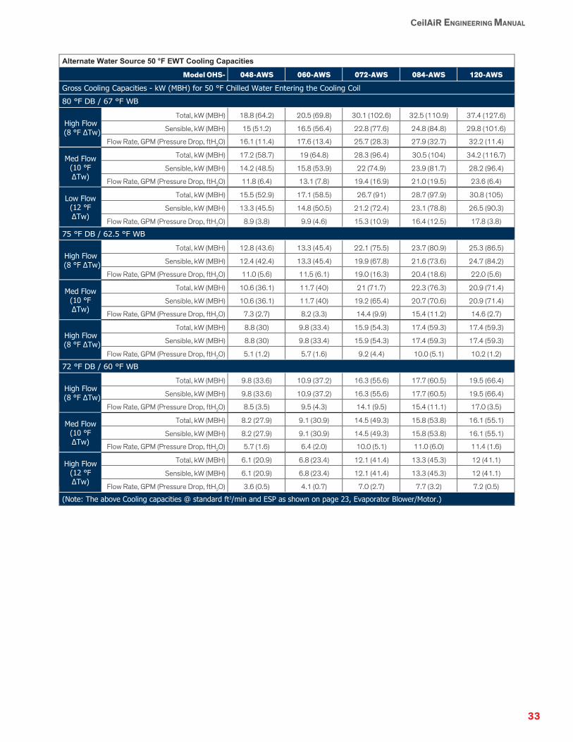
33
CeilAiR ENGINEERING MANUAL
Alternate Water Source 50 °F EWT Cooling Capacities
Model OHS- 048-AWS 060-AWS 072-AWS 084-AWS 120-AWS
Gross Cooling Capacities - kW (MBH) for 50 °F Chilled Water Entering the Cooling Coil 80 °F DB / 67 °F WB
High Flow (8 °F ΔTw)
Total, kW (MBH) 18.8 (64.2) 20.5 (69.8) 30.1 (102.6) 32.5 (110.9) 37.4 (127.6)
Sensible, kW (MBH) 15 (51.2) 16.5 (56.4) 22.8 (77.6) 24.8 (84.8) 29.8 (101.6)
Flow Rate, GPM (Pressure Drop, ftH2O) 16.1 (11.4) 17.6 (13.4) 25.7 (28.3) 27.9 (32.7) 32.2 (11.4)
Med Flow (10 °F ΔTw)
Total, kW (MBH) 17.2 (58.7) 19 (64.8) 28.3 (96.4) 30.5 (104) 34.2 (116.7)
Sensible, kW (MBH) 14.2 (48.5) 15.8 (53.9) 22 (74.9) 23.9 (81.7) 28.2 (96.4)
Flow Rate, GPM (Pressure Drop, ftH2O) 11.8 (6.4) 13.1 (7.8) 19.4 (16.9) 21.0 (19.5) 23.6 (6.4)
Low Flow (12 °F ΔTw)
Total, kW (MBH) 15.5 (52.9) 17.1 (58.5) 26.7 (91) 28.7 (97.9) 30.8 (105)
Sensible, kW (MBH) 13.3 (45.5) 14.8 (50.5) 21.2 (72.4) 23.1 (78.8) 26.5 (90.3)
Flow Rate, GPM (Pressure Drop, ftH2O) 8.9 (3.8) 9.9 (4.6) 15.3 (10.9) 16.4 (12.5) 17.8 (3.8)
75 °F DB / 62.5 °F WB
High Flow (8 °F ΔTw)
Total, kW (MBH) 12.8 (43.6) 13.3 (45.4) 22.1 (75.5) 23.7 (80.9) 25.3 (86.5)
Sensible, kW (MBH) 12.4 (42.4) 13.3 (45.4) 19.9 (67.8) 21.6 (73.6) 24.7 (84.2)
Flow Rate, GPM (Pressure Drop, ftH2O) 11.0 (5.6) 11.5 (6.1) 19.0 (16.3) 20.4 (18.6) 22.0 (5.6)
Med Flow (10 °F ΔTw)
Total, kW (MBH) 10.6 (36.1) 11.7 (40) 21 (71.7) 22.3 (76.3) 20.9 (71.4)
Sensible, kW (MBH) 10.6 (36.1) 11.7 (40) 19.2 (65.4) 20.7 (70.6) 20.9 (71.4)
Flow Rate, GPM (Pressure Drop, ftH2O) 7.3 (2.7) 8.2 (3.3) 14.4 (9.9) 15.4 (11.2) 14.6 (2.7)
High Flow (8 °F ΔTw)
Total, kW (MBH) 8.8 (30) 9.8 (33.4) 15.9 (54.3) 17.4 (59.3) 17.4 (59.3)
Sensible, kW (MBH) 8.8 (30) 9.8 (33.4) 15.9 (54.3) 17.4 (59.3) 17.4 (59.3)
Flow Rate, GPM (Pressure Drop, ftH2O) 5.1 (1.2) 5.7 (1.6) 9.2 (4.4) 10.0 (5.1) 10.2 (1.2)
72 °F DB / 60 °F WB
High Flow (8 °F ΔTw)
Total, kW (MBH) 9.8 (33.6) 10.9 (37.2) 16.3 (55.6) 17.7 (60.5) 19.5 (66.4)
Sensible, kW (MBH) 9.8 (33.6) 10.9 (37.2) 16.3 (55.6) 17.7 (60.5) 19.5 (66.4)
Flow Rate, GPM (Pressure Drop, ftH2O) 8.5 (3.5) 9.5 (4.3) 14.1 (9.5) 15.4 (11.1) 17.0 (3.5)
Med Flow (10 °F ΔTw)
Total, kW (MBH) 8.2 (27.9) 9.1 (30.9) 14.5 (49.3) 15.8 (53.8) 16.1 (55.1)
Sensible, kW (MBH) 8.2 (27.9) 9.1 (30.9) 14.5 (49.3) 15.8 (53.8) 16.1 (55.1)
Flow Rate, GPM (Pressure Drop, ftH2O) 5.7 (1.6) 6.4 (2.0) 10.0 (5.1) 11.0 (6.0) 11.4 (1.6)
High Flow (12 °F ΔTw)
Total, kW (MBH) 6.1 (20.9) 6.8 (23.4) 12.1 (41.4) 13.3 (45.3) 12 (41.1)
Sensible, kW (MBH) 6.1 (20.9) 6.8 (23.4) 12.1 (41.4) 13.3 (45.3) 12 (41.1)
Flow Rate, GPM (Pressure Drop, ftH2O) 3.6 (0.5) 4.1 (0.7) 7.0 (2.7) 7.7 (3.2) 7.2 (0.5)
(Note: The above Cooling capacities @ standard ft3/min and ESP as shown on page 23, Evaporator Blower/Motor.)

34
CeilAiR ENGINEERING MANUAL
Chilled Water Models
Chilled Water Air Handler Technical Data, 3.5−10.5 kW
Model OHS- 012-C 018-C 024-C 032-C 040-C
Chilled Water Control Valve - Sized for Medium Flow @ 75 °F DB / 62.5 °F WB EAT Conditions 2-way (standard) - Spring Actuated (Open/Close)
Size, in. 1/2 3/4 3/4 3/4 3/4
Cv 3.5 3.5 3.5 3.5 3.5
Valve Pressure Rating, psi 300 300 300 300 300
Pressure Drop, ftH2O-Total Unit 8.0 14.6. 19.4 14.2 22.6
3-way (optional) - Spring Actuated (Open/Close)
Size, in. 1/2 3/4 3/4 3/4 3/4
Cv 5.0 5.0 5.0 5.0 5.0
Valve Pressure Rating, psi 300 300 300 300 300
Pressure Drop, ftH2O-Total Unit 7.1 12.9 17.0 11.2 17.5
Chilled Water Coil - Aluminum Fin, Copper Tube Rows 4 4 4 4 4
Face Area, ft2 2.1 2.1 2.1 2.8 2.8
Evaporator Blower / Motor - DWDI Centrifugal Nominal Horsepower, hp 1/4 1/4 1/4 1/3 1/2
Rated Airflow, ft3/min @ inH2O ESP 500 @ 0.3 750 @ 0.3 900 @ 0.3 1000 @ 0.3 1415 @ 0.3
Standard Drive Method Direct Direct Direct Direct Direct
Optional Drive Method Belt Belt Belt Belt Belt
Reheat/Heat (Optional) - Performance Capacities Include Motor Heat Electric Reheat / Heat - kW values are nominal
Standard Heater, kW 5 5 5 5 5
Optional Heater, kW N/A N/A N/A N/A N/A
Hot Water Reheat / Heat - Reheat rated @ 180 °F Entering Water Temperature, EAT = 72 °F DB:
Total Capacity, kW (MBH) 6.1 (20.7) 9.5 (32.4) 10.2 (34.9) 14.8 (50.4) 16.2 (55.3)
Flow rate, GPM 1 2 2 3 3
Pressure Drop, ftH2O-Coil 0.1 0.3 0.3 0.3 0.3
Control Motorized Motorized Motorized Motorized Motorized
Steam Reheat / Heat - nominally Reheat rated @ 5 psi Steam, EAT = 72 °F DB:
Total Capacity, kW (MBH) 3.5 (12) 5.3 (18) 7 (24) 9.4 (32) 11.7 (40)
Condensate, lb/hr 13 19 25 34 42
Control Motorized Motorized Motorized Motorized Motorized
Humidification (Optional) - Electrode Steam Canister Humidifier with Adjustable Output Steam Output, lb/hr 2-5 2-5 2-5 2-5 2-5
Power Input, kW 1.7 1.7 1.7 1.7 1.7
Standard Control Cycling Cycling Cycling Cycling Cycling
Filters - 1 in. deep throwaway Nominal Size, in. 20×20 20×20 20×20 20×20 20×20
Quantity 1 1 1 1 1
Connection Sizes - Copper Humidifier Inlet OD, in. 1/4 1/4 1/4 1/4 1/4
Chilled Water In/Out OD, in. 5/8 7/8 7/8 7/8 7/8
Physical Size (Please refer to the dimensional drawings starting on page 57 for detailed dimensional data.) Approximate Weight, lb 120 125 125 160 170
-

35
CeilAiR ENGINEERING MANUAL
Chilled Water Air Handler Technical Data, 14−35 kW
OHS Model OHS-048-C OHS-060-C OHS-072-C OHS-084-C OHS-120-C
Chilled Water Control Valve - Sized for Medium Flow @ 75 °F DB / 62.5 °F WB EAT Conditions
2-way (standard) - Spring Actuated (Open/Close)
Size , in. 1 1 1 1 1
Cv 8.0 8.0 14.0 14.0 14.0
Valve Pressure Rating, psi 300 300 400 400 400
Pressure Drop, ftH2O-Total Unit 10.4 12.7 20.7 24.1 12.5
3-way (optional) - Spring Actuated (Open/Close)
Size, in. 1 1 1 1 1
Cv 7.0 7.0 14.0 14.0 14.0
Valve Pressure Rating, psi 300 300 400 400 400
Pressure Drop, ftH2O-Total Unit 11.8 14.4 20.7 24.1 12.5
Chilled Water Coil - Aluminum Fin, Copper Tube
Rows 4 4 4 4 4
Face Area, ft2 5.0 5.0 6.7 6.7 10.0
Evaporator Blower / Motor - DWDI Centrifugal - Belt Driven, Variable Pitch Pulleys
Nominal Horsepower, hp 1 1 1/2 1-1/2 2 3
Rated Airflow, ft3/min @ inH2O ESP 2200 @ 0.5 2500 @ 0.5 3000 @ 0.5 3350 @ 0.5 4400 @ 0.5
Drive Method Belt Belt Belt Belt Belt
Reheat/Heat (Optional) - Performance Capacities Include Motor Heat
Electric Reheat / Heat - kW values are nominal
Standard Heater, kW 10 10 10 10 10
Optional Heater, kW N/A N/A 15 15 15
Hot Water Reheat / Heat - Reheat rated @ 180 °F Entering Water Temperature, EAT = 72 °F DB
Total Capacity, kW (MBH) 28.5 (97.1) 32.6 (111.2) 28.7 (97.9) 29.3 (99.8) 38.2 (130.5)
Flow rate, GPM 4.0 5.0 3.0 3.0 10.0
Pressure Drop, ftH2O-Coil. 0.4 0.6 0.3 0.3 2.2
Control Motorized Motorized Motorized Motorized Motorized
Steam Reheat / Heat - nominally Reheat rated @ 5 psi Steam, EAT = 72 °F DB:
Total Capacity, kW (MBH) 14.1 (48) 17.6 (60) 21.1 (72) 26.4 (90) 35.2 (120)
Condensate, lb/hr 50 63 75 94 125
Control Motorized Motorized Motorized Motorized Motorized
Humidification (Optional) - Electrode Steam Canister Humidifier with Adjustable Output Steam Output, lb/hr 4-10 4-10 4-15 4-15 4-15
Power Input, kW 3.4 3.4 5.1 5.1 5.1
Standard Control Cycling Cycling Cycling Cycling Cycling
Filters - 1 in. deep throwaway
Nominal Size, in. 20×16 20×16 20×20 20×20 24×24
Quantity 2 2 2 2 2
Connection Sizes - Copper, (Water In/Out connections are sized for flow rates at 75 °F DB / 62.5 °F WB EAT conditions.)
Humidifier Inlet OD, in. 1/4 1/4 1/4 1/4 1/4
Chilled Water In/Out OD, in. 1 1/8 1 1/8 1 1/8 1 1/8 1 3/8
Physical Size (Please refer to the dimensional drawings starting on page 57 for detailed dimensional data.)
Approximate Weight, lb 280 290 365 415 495

36
CeilAiR ENGINEERING MANUAL
Chilled Water Air Handler Cooling Capacities, 3.5−12 kW
Model OHS- 012-C 018-C 024-C 032-C 040-C
Cooling Capacities - kW (MBH) for 45 °F EWT, 0% Glycol Solution (@ std ft3/min and ESP ratings) 80 °F DB / 67 °F WB, 50% RH
High Flow (8 °F ΔTw)
Total, kW (MBH) 6.7 (23) 9.1 (31.1) 10.4 (35.4) 12 (40.8) 15.2 (52)
Sensible, kW (MBH) 4.5 (15.3) 6.3 (21.4) 7.3 (24.8) 8.4 (28.7) 11 (37.7)
Flow Rate, GPM (Pressure Drop, ftH2O) 5.8 (19.6) 7.8 (34.0) 8.8 (43.1) 10.2 (23.3) 13.0 (36.8)
Med Flow
(10 °F ΔTw)
Total, kW (MBH) 6.2 (21.2) 8.5 (29.1) 9.7 (33.1) 11.1 (38) 14.3 (48.7)
Sensible, kW (MBH) 4.3 (14.6) 6 (20.5) 7 (23.8) 8 (27.4) 10.6 (36.1)
Flow Rate, GPM (Pressure Drop, ftH2O) 4.3 (11.2) 5.8 (19.8) 6.6 (25.1) 7.6 (13.6) 9.7 (21.5)
Low Flow
(12 °F ΔTw)
Total, kW (MBH) 5.7 (19.4) 7.9 (26.8) 9.1 (30.9) 10.2 (35) 13.3 (45.4)
Sensible, kW (MBH) 4 (13.8) 5.7 (19.5) 6.7 (22.8) 7.6 (26) 10.1 (34.5)
Flow Rate, GPM (Pressure Drop, ftH2O) 3.3 (6.8) 4.5 (12.2) 5.2 (15.8) 5.8 (8.3) 7.6 (13.4)
75 °F DB / 62.5 °F WB, 50% RH
High Flow (8 °F ΔTw)
Total, kW (MBH) 4.8 (16.5) 6.7 (22.8) 7.7 (26.1) 8.8 (30.2) 11.4 (38.9)
Sensible, kW (MBH) 3.8 (13) 5.4 (18.5) 6.3 (21.5) 7.2 (24.7) 9.6 (32.7)
Flow Rate, GPM (Pressure Drop, ftH2O) 4.2 (10.7) 5.7 (19.4) 6.5 (24.6) 7.6 (13.4) 9.7 (21.5)
Med Flow
(10 °F ΔTw)
Total, kW (MBH) 4.4 (15.1) 6.2 (21.1) 7.1 (24.4) 8.1 (27.7) 10.6 (36.2)
Sensible, kW (MBH) 3.6 (12.3) 5.2 (17.6) 6 (20.6) 6.9 (23.4) 9.1 (31.2)
Flow Rate, GPM (Pressure Drop, ftH2O) 3.1 (6.0) 4.2 (11.1) 4.9 (14.5) 5.6 (7.6) 7.3 (12.5)
Low Flow
(12 °F ΔTw)
Total, kW (MBH) 4.1 (13.8) 5.7 (19.4) 6.6 (22.5) 7.5 (25.5) 9.8 (33.3)
Sensible, kW (MBH) 3.4 (11.7) 4.9 (16.7) 5.7 (19.5) 6.5 (22.2) 8.6 (29.5)
Flow Rate, GPM (Pressure Drop, ftH2O) 2.3 (3.7) 3.3 (6.8) 3.8 (8.9) 4.3 (4.7) 5.6 (7.6)
72 °F DB / 60 °F WB, 50% RH
High Flow (8 °F ΔTw)
Total, kW (MBH) 4 (13.5) 5.5 (18.8) 6.4 (21.8) 7.3 (24.9) 9.5 (32.5)
Sensible, kW (MBH) 3.4 (11.7) 4.9 (16.7) 5.7 (19.5) 6.5 (22.2) 8.7 (29.6)
Flow Rate, GPM (Pressure Drop, ftH2O) 3.4 (7.5) 4.7 (13.6) 5.5 (17.8) 6.3 (9.5) 8.1 (15.4)
Med Flow
(10 °F ΔTw)
Total, kW (MBH) 3.6 (12.4) 5.1 (17.2) 5.8 (19.9) 6.7 (22.8) 8.7 (29.6)
Sensible, kW (MBH) 3.2 (11.1) 4.6 (15.7) 5.4 (18.4) 6.1 (21) 8.1 (27.8)
Flow Rate, GPM (Pressure Drop, ftH2O) 2.5 (4.2) 3.5 (7.7) 4.0 (10.0) 4.6 (5.4) 6.0 (8.6)
Low Flow
(12 °F ΔTw)
Total, kW (MBH) 3.3 (11.1) 4.5 (15.4) 5.2 (17.7) 5.9 (20.2) 7.6 (26)
Sensible, kW (MBH) 3 (10.3) 4.3 (14.5) 4.9 (16.9) 5.7 (19.3) 7.4 (25.3)
Flow Rate, GPM (Pressure Drop, ftH2O) 1.9 (2.2) 2.6 (4.5) 3.0 (5.7) 3.4 (3.1) 4.4 (4.9)
Continued on next page

37
CeilAiR ENGINEERING MANUAL
Chilled Water Air Handler Cooling Capacities, 3.5−12 kW (Con’t)
Model OHS- 012-C 018-C 024-C 032-C 040-C
80 °F DB / 65 °F WB, 45% RH
High Flow (8 °F ΔTw)
Total, kW (MBH) 5.9 (20.3) 8.1 (27.8) 9.3 (31.8) 10.8 (36.9) 13.9 (47.4)
Sensible, kW (MBH) 4.6 (15.6) 6.5 (22.1) 7.5 (25.7) 8.7 (29.7) 11.5 (39.2)
Flow Rate, GPM (Pressure Drop, ftH2O) 5.1 (15.7) 6.9 (27.5) 8.0 (35.4) 9.2 (19.5) 11.8 (30.8)
Med Flow
(10 °F ΔTw)
Total, kW (MBH) 5.5 (18.9) 7.7 (26.2) 8.8 (30.1) 10.1 (34.6) 13.1 (44.9)
Sensible, kW (MBH) 4.4 (15) 6.2 (21.3) 7.3 (24.8) 8.3 (28.5) 11.1 (37.8)
Flow Rate, GPM (Pressure Drop, ftH2O) 3.8 (9.1) 5.2 (16.3) 6.0 (21.1) 6.9 (11.5) 9.0 (18.5)
Low Flow
(12 °F ΔTw)
Total, kW (MBH) 5.1 (17.6) 7.2 (24.5) 8.3 (28.3) 9.5 (32.3) 12.3 (42.1)
Sensible, kW (MBH) 4.2 (14.3) 6 (20.5) 7 (23.9) 8 (27.3) 10.6 (36.3)
Flow Rate, GPM (Pressure Drop, ftH2O) 2.9 (5.7) 4.1 (10.4) 4.7 (13.4) 5.4 (7.2) 7.0 (11.7)
75 °F DB / 61 °F WB, 45% RH
High Flow (8 °F ΔTw)
Total, kW (MBH) 4.5 (15.2) 6.2 (21.2) 7.2 (24.4) 8.3 (28.2) 10.7 (36.6)
Sensible, kW (MBH) 3.9 (13.4) 5.6 (19.2) 6.5 (22.3) 7.5 (25.6) 10 (34)
Flow Rate, GPM (Pressure Drop, ftH2O) 3.8 (9.3) 5.4 (17.0) 6.1 (21.9) 7.0 (11.8) 9.2 (19.3)
Med Flow
(10 °F ΔTw)
Total, kW (MBH) 4.2 (14.2) 5.8 (19.8) 6.7 (22.7) 7.7 (26.2) 9.9 (33.9)
Sensible, kW (MBH) 3.8 (12.9) 5.4 (18.3) 6.2 (21.3) 7.1 (24.3) 9.4 (32.2)
Flow Rate, GPM (Pressure Drop, ftH2O) 2.9 (5.4) 4.0 (9.9) 4.6 (12.7) 5.3 (6.9) 6.8 (11.0)
Low Flow
(12 °F ΔTw)
Total, kW (MBH) 3.8 (13) 5.3 (18) 6 (20.6) 7 (23.8) 8 (27.5)
Sensible, kW (MBH) 3.6 (12.1) 5 (17.1) 5.8 (19.9) 6.7 (22.8) 8 (27.5)
Flow Rate, GPM (Pressure Drop, ftH2O) 2.2 (3.2) 3.0 (5.9) 3.5 (7.6) 4.0 (4.2) 4.6 (5.4)
72 °F DB / 58.5 °F WB, 45% RH
High Flow (8°F ΔTw)
Total, kW (MBH) 3.7 (12.7) 5.1 (17.4) 5.7 (19.4) 6.8 (23.3) 8.3 (28.4)
Sensible, kW (MBH) 3.6 (12.1) 5 (17.1) 5.7 (19.4) 6.7 (22.9) 8.3 (28.4)
Flow Rate, GPM (Pressure Drop, ftH2O) 3.2 (6.6) 4.4 (11.8) 4.9 (14.4) 5.9 (8.5) 7.1 (12.1)
Med Flow
(10 °F ΔTw)
Total, kW (MBH) 3.2 (10.8) 4.5 (15.3) 5.2 (17.8) 5.7 (19.4) 7.5 (25.7)
Sensible, kW (MBH) 3.2 (10.8) 4.5 (15.3) 5.2 (17.8) 5.7 (19.4) 7.5 (25.7)
Flow Rate, GPM (Pressure Drop, ftH2O) 2.2 (3.1) 3.1 (6.2) 3.6 (8.1) 3.9 (4.0) 5.2 (6.7)
Low Flow
(12 °F ΔTw)
Total, kW (MBH) 2.9 (9.7) 4 (13.8) 4.7 (16.1) 5.1 (17.2) 6.7 (22.9)
Sensible, kW (MBH) 2.9 (9.7) 4 (13.8) 4.7 (16.1) 5.1 (17.2) 6.7 (22.9)
Flow Rate, GPM (Pressure Drop, ftH2O) 1.7 (1.6) 2.3 (3.7) 2.7 (4.8) 2.9 (2.1) 3.9 (3.9)

38
CeilAiR ENGINEERING MANUAL
Chilled Water Air Handler Cooling Capacities, 14−35 kW
Model OHS- 048-C 060-C 072-C 084-C 120-C
Gross Cooling Capacity - kW (MBH) @ 45 °F EWT, 0% Glycol Solution (@ std ft3/min and ESP ratings). 80 °F DB / 67 °F WB, 50% RH
High Flow (8 °F ΔTw)
Total, kW (MBH) 24.6 (83.8) 26.7 (91.1) 39.3 (134.1) 42.3 (144.4) 48.9 (166.9)
Sensible, kW (MBH) 17.4 (59.3) 19.1 (65.3) 26.6 (90.8) 28.9 (98.7) 34.5 (117.9)
Flow Rate, GPM (Pressure Drop, ftH2O) 20.9 (18.6) 22.8 (21.9) 33.5 (46.3) 36.1 (53.2) 41.8 (18.6)
Med Flow
(10 °F ΔTw)
Total, kW (MBH) 22.7 (77.4) 24.9 (84.8) 36.8 (125.6) 39.6 (135.1) 45.1 (154)
Sensible, kW (MBH) 16.5 (56.4) 18.3 (62.4) 25.5 (87) 27.7 (94.6) 32.9 (112.2)
Flow Rate, GPM (Pressure Drop, ftH2O) 15.5 (10.7) 17.1 (12.7) 25.2 (27.5) 27.1 (31.5) 31.0 (10.7)
Low Flow
(12 °F ΔTw)
Total, kW (MBH) 20.5 (70) 22.6 (77.2) 34.4 (117.4) 37.1 (126.6) 40.8 (139.3)
Sensible, kW (MBH) 53.1) 17.3 (58.9) 24.4 (83.4) 26.6 (90.8) 30.9 (105.5)
Flow Rate, GPM (Pressure Drop, ftH2O) 11.7 (6.4) 13.0 (7.7) 19.6 (17.4) 21.2 (20.1) 23.4 (6.4 )
75 °F DB / 62.5 °F WB, 50% RH
High Flow (8 °F ΔTw)
Total, kW (MBH) 18 (61.3) 19.8 (67.5) 29 (99.1) 31.3 (106.7) 35.7 (121.9)
Sensible, kW (MBH) 15 (51.2) 16.6 (56.8) 23 (78.5) 25.1 (85.5) 29.8 (101.7)
Flow Rate, GPM (Pressure Drop, ftH2O) 15.4 (10.6) 17.0 (12.7) 24.8 (26.9) 26.8 (30.8) 30.8 (10.6)
Med Flow
(10 °F ΔTw)
Total, kW (MBH) 16.2 (55.2) 17.9 (61.1) 27.3 (93.3) 29.5 (100.6) 32.1 (109.7)
Sensible, kW (MBH) 14.1 (48) 15.6 (53.3) 22.2 (75.7) 24.2 (82.4) 27.9 (95.3)
Flow Rate, GPM (Pressure Drop, ftH2O) 11.1 (5.8) 12.4 (7.1) 18.8 (16.1) 20.3 (18.5) 22.2 (5.8)
Low Flow
(12 °F ΔTw)
Total, kW (MBH) 14.4 (49.2) 15.9 (54.4) 25.6 (87.3) 27.8 (94.8) 28.6 (97.6)
Sensible, kW (MBH) 13 (44.4) 14.4 (49.3) 21.3 (72.6) 23.3 (79.4) 25.8 (88.2)
Flow Rate, GPM (Pressure Drop, ftH2O) 8.3 (3.4) 9.2 (4.1) 14.6 (10.2) 15.9 (11.9) 16.6 (3.4)
72 °F DB / 60 °F WB, 50% RH
High Flow (8 °F ΔTw)
Total, kW (MBH) 14.7 (50.1) 16.1 (55.1) 24.3 (83.1) 26.2 (89.6) 29.2 (99.5)
Sensible, kW (MBH) 13.5 (45.9) 14.9 (50.8) 21 (71.6) 22.9 (78) 26.7 (91.2)
Flow Rate, GPM (Pressure Drop, ftH2O) 12.6 (7.4) 13.9 (8.8) 20.9 (19.6) 22.5 (22.6) 25.2 (7.4)
Med Flow
(10 °F ΔTw)
Total, kW (MBH) 12.7 (43.3) 13.9 (47.5) 23 (78.6) 24.9 (84.9) 25.2 (86)
Sensible, kW (MBH) 12.2 (41.7) 13.5 (46) 20.2 (69.1) 22.1 (75.2) 24.2 (82.7)
Flow Rate, GPM (Pressure Drop, ftH2O) 8.7 (3.7) 9.6 (4.5) 15.8 (11.9) 17.2 (13.7) 17.4 (3.7)
Low Flow
(12 °F ΔTw)
Total, kW (MBH) 10 (34.1) 11.1 (37.9) 21 (71.6) 22.8 (77.8) 19.8 (67.6)
Sensible, kW (MBH) 10 (34.1) 11.1 (37.9) 19 (64.9) 20.8 (70.8) 19.8 (67.6)
Flow Rate, GPM (Pressure Drop, ftH2O) 5.8 (1.6) 6.4 (2.1) 12.0 (7.2) 13.1 (8.4) 11.6 (1.6)

39
CeilAiR ENGINEERING MANUAL
Chilled Water Air Handler Cooling Capacities, 14−35 kW (Con’t)
Model OHS- 048-C 060-C 072-C 084-C 120-C
80 °F DB / 65 °F WB, 45% RH
High Flow (8 °F ΔTw)
Total, kW (MBH) 22.1 (75.6) 24.2 (82.5) 35.3 (120.4) 38.1 (130) 44.1 (150.5)
Sensible, kW (MBH) 18.1 (61.7) 20 (68.1) 27.4 (93.6) 29.9 (102.2) 35.9 (122.7)
Flow Rate, GPM (Pressure Drop, ftH2O) 18.9 (15.5) 20.7 (18.3) 30.2 (38.4) 32.6 (44.1) 37.8 (15.5)
Med Flow
(10 °F ΔTw)
Total, kW (MBH) 20.5 (70.1) 22.6 (77.2) 33.5 (114.2) 36.1 (123.2) 40.9 (139.4)
Sensible, kW (MBH) 17.3 (58.9) 19.2 (65.4) 26.6 (90.7) 29 (98.9) 34.3 (117.2)
Flow Rate, GPM (Pressure Drop, ftH2O) 14.1 (8.9) 15.5 (10.7) 23.0 (23.3) 24.8 (26.7) 28.2 (8.9)
Low Flow
(12 °F ΔTw)
Total, kW (MBH) 18.9 (64.4) 22.3 (76.1) 31.8 (108.6) 34.4 (117.2) 37.5 (128.1)
Sensible, kW (MBH) 16.4 (55.9) 18.2 (62.1) 25.8 (88) 28.1 (96) 32.6 (111.1)
Flow Rate, GPM (Pressure Drop, ftH2O) 10.8 (5.5) 11.9 (6.6) 18.2 (15.1) 19.6 (17.4) 21.6 (5.5)
75 °F DB / 61 °F WB, 45% RH
High Flow (8 °F ΔTw)
Total, kW (MBH) 16.8 (57.2) 18.4 (62.8) 27.3 (93.1) 29.5 (100.5) 33.4 (113.8)
Sensible, kW (MBH) 15.6 (53.1) 17.2 (58.8) 24 (81.9) 26.2 (89.3) 31 (105.6)
Flow Rate, GPM (Pressure Drop, ftH2O) 14.4 (9.4) 15.9 (11.2) 23.4 (24.1) 25.3 (27.8) 28.8 (9.4)
Med Flow
(10 °F ΔTw)
Total, kW (MBH) 14.9 (50.8) 16.4 (55.9) 26.2 (89.3) 28.2 (96.1) 29.6 (101)
Sensible, kW (MBH) 14.4 (49.2) 15.9 (54.4) 23.3 (79.7) 25.4 (86.7) 28.6 (97.6)
Flow Rate, GPM (Pressure Drop, ftH2O) 10.2 (5.0) 11.3 (6.0) 18.0 (14.9) 19.4 (17.2) 20.4 (5.0)
High Flow
(12 °F ΔTw)
Total, kW (MBH) 12.4 (42.3) 13.7 (46.9) 24.7 (84.2) 26.7 (91.1) 24.6 (83.9)
Sensible, kW (MBH) 12.4 (42.3) 13.7 (46.9) 22.4 (76.5) 24.4 (83.4) 24.6 (83.9)
Flow Rate, GPM (Pressure Drop, ftH2O) 7.1 (2.6) 7.9 (3.1) 14.1 (9.6) 15.3 (11.1) 14.2 (2.6)
72 °F DB / 58.5 °F WB, 45% RH
High Flow (8 °F ΔTw)
Total, kW (MBH) 13.2 (44.9) 14.6 (49.7) 23.4 (79.7) 25 (85.3) 26.1 (89.1)
Sensible, kW (MBH) 13.2 (44.9) 14.6 (49.7) 22.1 (75.4) 23.9 (81.7) 26.1 (89.1)
Flow Rate, GPM (Pressure Drop, ftH2O) 11.3 (6.0) 12.5 (7.3) 20.0 (18.2) 21.4 (20.6) 22.6 (6.0)
Med Flow
(10 °F ΔTw)
Total, kW (MBH) 11.7 (39.9) 13 (44.2) 19.6 (66.8) 21.4 (73) 23.2 (79.1)
Sensible, kW (MBH) 11.7 (39.9) 13 (44.2) 19.6 (66.8) 21.4 (73) 23.2 (79.1)
Flow Rate, GPM (Pressure Drop, ftH2O) 8.1 (3.2) 9.0 (3.9) 13.4 (8.8) 14.8 (10.5) 16.2 (3.2)
Low Flow
(12 °F ΔTw)
Total, kW (MBH) 10 (34) 11.1 (37.8) 17.7 (60.4) 19.3 (65.9) 19.7 (67.3)
Sensible, kW (MBH) 10 (34) 11.1 (37.8) 17.7 (60.4) 19.3 (65.9) 19.7 (67.3)
Flow Rate, GPM (Pressure Drop, ftH2O) 5.7 (1.6) 6.4 (2.0) 10.2 (5.3) 11.1 (6.3) 11.4 (1.6)

40
CeilAiR ENGINEERING MANUAL
Chilled Water 42 °F EWT Cooling Capacities
Model OHS- 012-C 018-C 024-C 032-C 040-C
Gross Cooling Capacities - kW (MBH) for 42 °F Chilled Water Entering the Cooling Coil 80 °F DB / 67 °F WB
High Flow (8 °F ΔTw)
Total, kW (MBH) 7.7 (26.3) 10.5 (35.7) 11.9 (40.6) 13.6 (46.5) 17.4 (59.3)
Sensible, kW (MBH) 4.9 (16.8) 6.9 (23.4) 7.9 (27.1) 9.2 (31.4) 12 (41)
Flow Rate, GPM (Pressure Drop, ftH2O) 6.6 (25.0) 8.9 (43.9) 10.1 (55.8) 11.6 (29.8) 14.8 (47.2)
Med Flow (10 °F ΔTw)
Total, kW (MBH) 7.2 (24.6) 9.8 (33.5) 11.2 (38.2) 12.8 (43.7) 16.3 (55.8)
Sensible, kW (MBH) 4.7 (16) 6.6 (22.5) 7.6 (26) 8.8 (30) 11.5 (39.3)
Flow Rate, GPM (Pressure Drop, ftH2O) 4.9 (14.8) 6.7 (25.8) 7.6 (32.9) 8.7 (17.6) 11.1 (27.7)
Low Flow (12 °F ΔTw)
Total, kW (MBH) 6.6 (22.7) 9.1 (31.2) 10.5 (35.8) 11.8 (40.4) 15.3 (52.3)
Sensible, kW (MBH) 4.4 (15.2) 6.3 (21.4) 7.3 (24.9) 8.3 (28.5) 11 (37.6)
Flow Rate, GPM (Pressure Drop, ftH2O) 3.8 (9.1) 5.2 (16.1) 6.0 (20.8) 6.7 (10.9) 8.7 (17.6)
75 °F DB / 62.5 °F WB
High Flow (8 °F ΔTw)
Total, kW (MBH) 5.7 (19.5) 7.8 (26.8) 9 (30.6) 10.3 (35.2) 13.2 (45.2)
Sensible, kW (MBH) 4.2 (14.4) 6 (20.3) 6.9 (23.6) 8 (27.1) 10.5 (35.8)
Flow Rate, GPM (Pressure Drop, ftH2O) 4.9 (14.5) 6.7 (25.9) 7.6 (33.2) 8.8 (17.9) 11.3 (28.4)
Med Flow (10 °F ΔTw)
Total, kW (MBH) 5.2 (17.9) 7.3 (24.8) 8.4 (28.6) 9.5 (32.5) 12.4 (42.3)
Sensible, kW (MBH) 4 (13.6) 5.7 (19.4) 6.6 (22.5) 7.5 (25.7) 10 (34.2)
Flow Rate, GPM (Pressure Drop, ftH2O) 3.6 (8.2) 5.0 (15.1) 5.7 (19.3) 6.5 (10.2) 8.5 (16.7)
Low Flow (12 °F ΔTw)
Total, kW (MBH) 4.8 (16.4) 6.7 (22.9) 7.8 (26.7) 8.8 (29.9) 11.4 (39.1)
Sensible, kW (MBH) 3.8 (12.9) 5.4 (18.4) 6.3 (21.4) 7.1 (24.4) 9.5 (32.5)
Flow Rate, GPM (Pressure Drop, ftH2O) 2.8 (5.0) 3.8 (9.2) 4.4 (11.9) 5.0 (6.3) 6.5 (10.2)
72 °F DB / 60 °F WB
High Flow (8 °F ΔTw)
Total, kW (MBH) 4.7 (16.1) 6.6 (22.4) 7.5 (25.8) 8.7 (29.6) 11.2 (38.4)
Sensible, kW (MBH) 3.8 (13) 5.4 (18.5) 6.3 (21.5) 7.2 (24.6) 9.6 (32.7)
Flow Rate, GPM (Pressure Drop, ftH2O) 4.1 (10.4) 5.7 (19.0) 6.4 (24.0) 7.4 (13.0) 9.6 (21.0)
MedFlow (10 °F ΔTw)
Total, kW (MBH) 4.3 (14.8) 6.1 (20.7) 7 (23.9) 7.9 (27.1) 10.4 (35.4)
Sensible, kW (MBH) 3.6 (12.3) 5.1 (17.5) 6 (20.4) 6.8 (23.2) 9.1 (31)
Flow Rate, GPM (Pressure Drop, ftH2O) 3.0 (5.9) 4.2 (10.8) 4.8 (14.0) 5.4 (7.4) 7.1 (12.1)
Low Flow (12 °F ΔTw)
Total, kW (MBH) 4 (13.5) 5.6 (19) 6.4 (22) 7.3 (24.9) 9.5 (32.5)
Sensible, kW (MBH) 3.4 (11.6) 4.8 (16.5) 5.7 (19.3) 6.4 (21.9) 8.5 (29.1)
Flow Rate, GPM (Pressure Drop, ftH2O) 2.3 (3.4) 3.2 (6.6) 3.7 (8.6) 4.2 (4.5) 5.4 (7.3)

41
CeilAiR ENGINEERING MANUAL
Chilled Water 42 °F EWT Cooling Capacities
Model OHS- 048-C 060-C 072-C 084-C 120-C
Gross Cooling Capacities - kW (MBH) for 42 °F Chilled Water Entering the Cooling Coil 80 °F DB / 67 °F WB
High Flow (8 °F ΔTw)
Total, kW (MBH) 28.2 (96.3) 30.7 (104.8) 45 (153.4) 48.5 (165.4) 56.2 (191.9)
Sensible, kW (MBH) 19 (64.7) 20.8 (71.1) 29.1 (99.3) 31.6 (107.9) 37.7 (128.6)
Flow Rate, GPM (Pressure Drop, ftH2O) 24.0 (24.2) 26.2 (28.4) 38.3 (59.6) 41.3 (68.6) 42.0 (24.2)
Med Flow (10 °F ΔTw)
Total, kW (MBH) 26.3 (89.7) 28.7 (97.8) 42.4 (144.6) 45.6 (155.7) 52.3 (178.6)
Sensible, kW (MBH) 18.1 (61.7) 19.9 (67.9) 27.9 (95.3) 30.3 (103.5) 35.9 (122.6)
Flow Rate, GPM (Pressure Drop, ftH2O) 17.9 (14.1) 19.6 (16.6) 28.9 (35.7) 31.2 (41.0) 35.8 (14.1)
Low Flow (12 °F ΔTw)
Total, kW (MBH) 23.8 (81.3) 17.5 (59.6) 39.7 (135.6) 42.9 (146.3) 47.5 (162)
Sensible, kW (MBH) 17 (57.9) 18.8 (64.2) 26.7 (91.3) 29.1 (99.3) 33.7 (115.2)
Flow Rate, GPM (Pressure Drop, ftH2O) 13.6 (8.4) 15.0 (10.1) 22.6 (22.7) 24.5 (26.3) 27.2 (8.4)
75 °F DB / 62.5 °F WB
High Flow (8 °F ΔTw)
Total, kW (MBH) 21.1 (72.1) 23.2 (79.1) 33.9 (115.7) 36.5 (124.7) 42.1 (143.5)
Sensible, kW (MBH) 16.5 (56.2) 18.2 (62.1) 25.2 (86.1) 27.5 (93.7) 32.7 (111.7)
Flow Rate, GPM (Pressure Drop, ftH2O) 18.1 (14.3) 19.9 (17.1) 28.9 (35.8) 31.2 (41.1) 36.2 (14.3)
Med Flow (10 °F ΔTw)
Total, kW (MBH) 19.1 (65.3) 21.1 (72) 31.9 (108.8) 34.3 (117.1) 38.1 (129.9)
Sensible, kW (MBH) 15.5 (52.8) 17.2 (58.6) 24.3 (82.8) 26.4 (90) 30.7 (104.9)
Flow Rate, GPM (Pressure Drop, ftH2O) 13.1 (7.9) 14.5 (9.6) 21.8 (21.4) 23.5 (24.5) 26.2 (7.9)
Low Flow (12 °F ΔTw)
Total, kW (MBH) 17.3 (58.9) 19.1 (65.2) 29.7 (101.5) 32.3 (110.2) 34.3 (117.1)
Sensible, kW (MBH) 14.5 (49.4) 16.1 (55) 23.2 (79.2) 25.4 (86.6) 28.8 (98.2)
Flow Rate, GPM (Pressure Drop, ftH2O) 9.9 (4.7) 11.0 (5.7) 17.0 (13.6) 18.5 (15.8) 19.8 (4.7)
72 °F DB / 60 °F WB
High Flow (8 °F ΔTw)
Total, kW (MBH) 17.6 (59.9) 19.3 (65.9) 28.7 (97.8) 30.9 (105.3) 34.9 (119.2)
Sensible, kW (MBH) 14.9 (50.8) 16.5 (56.3) 23 (78.6) 25.1 (85.5) 29.6 (101)
Flow Rate, GPM (Pressure Drop, ftH2O) 15.1 (10.2) 16.6 (12.3) 24.5 (26.4) 26.4 (30.3) 30.2 (10.2)
MedFlow (10 °F ΔTw)
Total, kW (MBH) 15.8 (53.9) 17.4 (59.5) 27 (92) 29.1 (99.2) 31.4 (107.1)
Sensible, kW (MBH) 13.9 (47.5) 15.4 (52.7) 22.2 (75.6) 24.1 (82.4) 27.6 (94.3)
Flow Rate, GPM (Pressure Drop, ftH2O) 10.8 (5.6) 12.0 (6.8) 18.5 (15.8) 20.0 (18.2) 21.6 (5.6)
Low Flow (12 °F ΔTw)
Total, kW (MBH) 13.9 (47.4) 15.3 (52.2) 24.9 (84.9) 27 (92.2) 27.6 (94.1)
Sensible, kW (MBH) 12.8 (43.5) 14.1 (48.2) 21.1 (71.9) 23 (78.5) 25.3 (86.3)
Flow Rate, GPM (Pressure Drop, ftH2O) 8.0 (3.2) 8.8 (3.8) 14.2 (9.9) 15.5 (11.4) 16.0 (3.2)

42
CeilAiR ENGINEERING MANUAL
Chilled Water 50 °F EWT Cooling Capacities
Model OHS- 012-C 018-C 024-C 032-C 040-C
Gross Cooling Capacities - kW (MBH) for 50 °F Chilled Water Entering the Cooling Coil 80 °F DB / 67 °F WB
High Flow (8 °F ΔTw)
Total, kW (MBH) 5.1 (17.3) 7 (23.7) 7.9 (27.1) 9.2 (31.6) 11.8 (40.3)
Sensible, kW (MBH) 3.8 (13) 5.4 (18.4) 6.3 (21.4) 7.2 (24.7) 9.5 (32.6)
Flow Rate, GPM (Pressure Drop, ftH2O) 4.4 (11.6) 6.0 (20.6) 6.8 (26.0) 7.9 (14.5) 10.1 (22.7)
Med Flow (10 °F ΔTw)
Total, kW (MBH) 4.7 (15.9) 6.5 (22.1) 7.4 (25.4) 8.5 (29.1) 10.8 (36.8)
Sensible, kW (MBH) 3.6 (12.3) 5.2 (17.6) 6 (20.5) 6.9 (23.5) 9.2 (31.3)
Flow Rate, GPM (Pressure Drop, ftH2O) 3.2 (6.5) 4.5 (12.0) 5.1 (15.3) 5.8 (8.2) 7.6 (13.4)
Low Flow
(12 °F ΔTw
Total, kW (MBH) 4.3 (14.6) 6 (20.4) 6.9 (23.7) 7.8 (26.8) 10.3 (35.1)
Sensible, kW (MBH) 3.4 (11.7) 4.9 (16.8) 5.8 (19.6) 6.5 (22.3) 8.7 (29.8)
Flow Rate, GPM (Pressure Drop, ftH2O) 2.5 (4.0) 3.4 (7.4) 4.0 (9.7) 4.5 (5.1) 5.9 (8.3)
75 °F DB / 62.5 °F WB
High Flow (8 °F ΔTw)
Total, kW (MBH) 3.5 (12.1) 4.9 (16.7) 5.6 (19.2) 6.6 (22.4) 8.4 (28.8)
Sensible, kW (MBH) 3.2 (11) 4.6 (15.6) 5.3 (18.2) 6.1 (20.9) 8.1 (27.6)
Flow Rate, GPM (Pressure Drop, ftH2O) 3.1 (6.1) 4.2 (10.9) 4.8 (14.0) 5.7 (7.8) 7.2 (12.3)
Med Flow (10 °F ΔTw)
Total, kW (MBH) 3.2 (10.9) 4.4 (14.9) 5 (17) 5.8 (19.9) 6.9 (23.4)
Sensible, kW (MBH) 3 (10.3) 4.2 (14.4) 4.9 (16.7) 5.7 (19.3) 6.9 (23.4)
Flow Rate, GPM (Pressure Drop, ftH2O) 2.2 (3.3) 3.0 (5.8) 3.4 (7.4) 4.0 (4.2) 4.8 (5.7)
High Flow (12 °F ΔTw)
Total, kW (MBH) 2.6 (8.7) 3.6 (12.4) 4.2 (14.4) 4.5 (15.4) 6 (20.4)
Sensible, kW (MBH) 2.6 (8.7) 3.6 (12.4) 4.2 (14.4) 4.5 (15.4) 6 (20.4)
Flow Rate, GPM (Pressure Drop, ftH2O) 1.5 (1.3) 2.1 (2.9) 2.4 (3.9) 2.6 (1.7) 3.5 (3.1)
72 °F DB / 60 °F WB
High Flow (8 °F ΔTw)
Total, kW (MBH) 2.6 (9) 3.7 (12.7) 4.3 (14.8) 4.8 (16.2) 6.3 (21.5)
Sensible, kW (MBH) 2.6 (9) 3.7 (12.7) 4.3 (14.8) 4.8 (16.2) 6.3 (21.5)
Flow Rate, GPM (Pressure Drop, ftH2O) 2.3 (3.5) 3.2 (6.6) 3.7 (8.7) 4.1 (4.3) 5.5 (7.3)
Med Flow (10 °F ΔTw)
Total, kW (MBH) 2.3 (7.9) 3.3 (11.3) 3.8 (13.1) 4.1 (14.1) 5.5 (18.6)
Sensible, kW (MBH) 2.3 (7.9) 3.3 (11.3) 3.8 (13.1) 4.1 (14.1) 5.5 (18.6)
Flow Rate, GPM (Pressure Drop, ftH2O) 1.6 (1.6) 2.3 (3.5) 2.7 (4.6) 2.9 (2.1) 3.8 (3.7)
High Flow (12 °F ΔTw)
Total, kW (MBH) 2 (6.7) 2.8 (9.6) 3.3 (11.1) 3.4 (11.5) 4.5 (15.3)
Sensible, kW (MBH) 2 (6.7) 2.8 (9.6) 3.3 (11.1) 3.4 (11.5) 4.5 (15.3)
Flow Rate, GPM (Pressure Drop, ftH2O) 1.1 (0.7) 1.6 (1.6) 1.9 (2.3) 2.0 (0.8) 2.6 (1.7)
(Note: The above Cooling capacities @ standard ft3/min and ESP as shown on page 34, Evaporator Blower/Motor.)

43
CeilAiR ENGINEERING MANUAL
Chilled Water 50 °F EWT Cooling Capacities
Model OHS- 048-C 060-C 072-C 084-C 120-C
Gross Cooling Capacities - kW (MBH) for 50 °F Chilled Water Entering the Cooling Coil 80 °F DB / 67 °F WB
High Flow (8 °F ΔTw)
Total, kW (MBH) 18.8 (64.2) 20.5 (69.8) 30.1 (102.6) 32.5 (110.9) 37.4 (127.6)
Sensible, kW (MBH) 15 (51.2) 16.5 (56.4) 22.8 (77.6) 24.8 (84.8) 29.8 (101.6)
Flow Rate, GPM (Pressure Drop, ftH2O) 16.1 (11.4) 17.6 (13.4) 25.7 (28.3) 27.9 (32.7) 32.2 (11.4)
Med Flow (10 °F ΔTw)
Total, kW (MBH) 17.2 (58.7) 19 (64.8) 28.3 (96.4) 30.5 (104) 34.2 (116.7)
Sensible, kW (MBH) 14.2 (48.5) 15.8 (53.9) 22 (74.9) 23.9 (81.7) 28.2 (96.4)
Flow Rate, GPM (Pressure Drop, ftH2O) 11.8 (6.4) 13.1 (7.8) 19.4 (16.9) 21.0 (19.5) 23.6 (6.4)
Low Flow (12 °F ΔTw
Total, kW (MBH) 15.5 (52.9) 17.1 (58.5) 26.7 (91) 28.7 (97.9) 30.8 (105)
Sensible, kW (MBH) 13.3 (45.5) 14.8 (50.5) 21.2 (72.4) 23.1 (78.8) 26.5 (90.3)
Flow Rate, GPM (Pressure Drop, ftH2O) 8.9 (3.8) 9.9 (4.6) 15.3 (10.9) 16.4 (12.5) 17.8 (3.8)
75 °F DB / 62.5 °F WB High Flow (8 °F ΔTw)
Total, kW (MBH) 12.8 (43.6) 13.3 (45.4) 22.1 (75.5) 23.7 (80.9) 25.3 (86.5)
Sensible, kW (MBH) 12.4 (42.4) 13.3 (45.4) 19.9 (67.8) 21.6 (73.6) 24.7 (84.2)
Flow Rate, GPM (Pressure Drop, ftH2O) 11.0 (5.6) 11.5 (6.1) 19.0 (16.3) 20.4 (18.6) 22.0 (5.6)
Med Flow (10 °F ΔTw)
Total, kW (MBH) 10.6 (36.1) 11.7 (40) 21 (71.7) 22.3 (76.3) 20.9 (71.4)
Sensible, kW (MBH) 10.6 (36.1) 11.7 (40) 19.2 (65.4) 20.7 (70.6) 20.9 (71.4)
Flow Rate, GPM (Pressure Drop, ftH2O) 7.3 (2.7) 8.2 (3.3) 14.4 (9.9) 15.4 (11.2) 14.6 (2.7)
High Flow (12 °F ΔTw)
Total, kW (MBH) 8.8 (30) 9.8 (33.4) 15.9 (54.3) 17.4 (59.3) 17.4 (59.3)
Sensible, kW (MBH) 8.8 (30) 9.8 (33.4) 15.9 (54.3) 17.4 (59.3) 17.4 (59.3)
Flow Rate, GPM (Pressure Drop, ftH2O) 5.1 (1.2) 5.7 (1.6) 9.2 (4.4) 10.0 (5.1) 10.2 (1.2)
72 °F DB / 60 °F WB High Flow (8 °F ΔTw)
Total, kW (MBH) 9.8 (33.6) 10.9 (37.2) 16.3 (55.6) 17.7 (60.5) 19.5 (66.4)
Sensible, kW (MBH) 9.8 (33.6) 10.9 (37.2) 16.3 (55.6) 17.7 (60.5) 19.5 (66.4)
Flow Rate, GPM (Pressure Drop, ftH2O) 8.5 (3.5) 9.5 (4.3) 14.1 (9.5) 15.4 (11.1) 17.0 (3.5)
Med Flow (10 °F ΔTw)
Total, kW (MBH) 8.2 (27.9) 9.1 (30.9) 14.5 (49.3) 15.8 (53.8) 16.1 (55.1)
Sensible, kW (MBH) 8.2 (27.9) 9.1 (30.9) 14.5 (49.3) 15.8 (53.8) 16.1 (55.1)
Flow Rate, GPM (Pressure Drop, ftH2O) 5.7 (1.6) 6.4 (2.0) 10.0 (5.1) 11.0 (6.0) 11.4 (1.6)
High Flow (12 °F ΔTw)
Total, kW (MBH) 6.1 (20.9) 6.8 (23.4) 12.1 (41.4) 13.3 (45.3) 12 (41.1)
Sensible, kW (MBH) 6.1 (20.9) 6.8 (23.4) 12.1 (41.4) 13.3 (45.3) 12 (41.1)
Flow Rate, GPM (Pressure Drop, ftH2O) 3.6 (0.5) 4.1 (0.7) 7.0 (2.7) 7.7 (3.2) 7.2 (0.5)
(Note: The above Cooling capacities @ standard ft3/min and ESP as shown on page 35, Evaporator Blower/Motor.)

44
CeilAiR ENGINEERING MANUAL
Electrical Data (FLA / MCA / MFS)
1. Electrical data is based on standard performance and component selection per the Technical Specifications/Performance Capacity section of this document. Please consult your local sales representative for “special” equipment electrical data.
2. Electrical data is the same for horizontal and standard discharge cabinets.
3. High Static Pressure Belt-Drive Option - Electrical data in the pages to follow are based on standard CFMs and external static pressures. Please consult your local sales representative for component and electrical rating data for this option.
4. Current draws in the following tables are specified as:
FLA = Full Load Amps MCA = Minimum Circuit Amps (wire size amps) MFS = Maximum Fuse Size

45
CeilAiR ENGINEERING MANUAL
DX Air, Water, and Glycol Cooled
With Condensate Pump (OHS-012 − OHS-060 AS)
Model
OHS-012-AS OHS-018-AS OHS-024-AS OHS-032-AS OHS-040-AS OHS-048-AS OHS-060-AS
FLA MCA MFS FLA MCA MFS FLA MCA MFS FLA MCA MFS FLA MCA MFS FLA MCA MFS FLA MCA MFS
COOLING and CONDENSATE PUMP ONLY, with or without Hot Gas, Hot Water or Steam Reheat
208/1/60 12.9 18.4 25.0 16.0 21.5 30.0 18.7 26.9 40.0 21.1 30.2 45.0 22.4 31.5 45.0 N/A N/A
277/1/60 10.4 15.9 20.0 12.2 17.0 25.0 14.1 21.0 30 17.0 24.3 35.0 18.1 25.4 35.0 N/A N/A
208/3/60 N/A N/A 15.5 19.2 25 17.1 23.8 35.0 18.4 25.1 35.0 N/A N/A
460/3/60 N/A N/A 7.1 9.5 15 7.9 11.7 15.0 8.6 12.4 15.0 N/A N/A
COOLING, CONDENSATE PUMP, and ELECTRIC REHEAT/HEAT, with or without Humidifier
208/1/60 34.3 45.2 50.0 37.4 48.2 50.0 40.1 53.6 60.0 42.5 56.9 60.0 43.8 58.2 60.0 N/A N/A
277/1/60 28.5 38.5 40.0 30.3 39.7 40.0 32.2 43.7 50.0 35.1 46.9 50.0 36.2 48.0 50.0 N/A N/A
208/3/60 N/A N/A 27.9 34.7 40.0 29.5 39.3 45.0 30.8 40.6 45.0 N/A N/A
460/3/60 N/A N/A 13.4 17.4 20.0 14.2 19.6 20.0 14.9 20.3 25.0 N/A N/A
COOLING, CONDENSATE PUMP, and HUMIDIFIER only, with or without Hot Gas, Hot Water or Steam Reheat (No Electric Reheat/Heat)
208/1/60 21.1 26.6 35.0 24.2 29.7 40.0 26.9 35.0 50.0 29.3 38.4 50.0 30.6 39.7 50.0 N/A N/A
277/1/60 16.5 22.0 30.0 18.3 23.1 30.0 20.2 27.1 35.0 23.1 30.4 40.0 24.2 31.5 45.0 N/A N/A
208/3/60 N/A N/A 23.7 27.4 35.0 25.3 32.0 40.0 26.6 33.3 45.0 N/A N/A
460/3/60 N/A N/A 10.8 13.2 15.0 11.6 15.4 20.0 12.3 16.1 20.0 N/A N/A
Without Condensate Pump (OHS-012 − OHS-060 AS)
Model OHS-012-AS OHS-018-AS OHS-024-AS OHS-032-AS OHS-040-AS OHS-048-AS OHS-060-AS
FLA MCA MFS FLA MCA MFS FLA MCA MFS FLA MCA MFS FLA MCA MFS FLA MCA MFS FLA MCA MFS
COOLING ONLY, with or without Hot Gas, Hot Water or Steam Reheat (No Condensate Pump)
208/1/60 11.7 17.2 25.0 14.8 20.3 30.0 17.5 25.6 40.0 19.9 29.0 45.0 21.2 30.3 45.0 N/A N/A
277/1/60 9.2 14.7 20.0 11.0 15.8 20.0 12.9 19.8 30.0 15.8 23.1 35.0 16.9 24.2 35.0 N/A N/A
208/3/60 N/A N/A 14.3 18.0 25.0 15.9 22.6 30.0 17.2 23.9 35.0 N/A N/A
460/3/60 N/A N/A 6.6 8.9 15.0 7.4 11.2 15.0 8.1 11.9 15.0 N/A N/A
COOLING and ELECTRIC REHEAT/HEAT, with or without Humidifier (No Condensate Pump)
208/1/60 33.1 44.0 45.0 36.2 47.0 50.0 38.9 52.4 60.0 41.3 55.7 60.0 42.6 57 60.0 N/A N/A
277/1/60 27.3 37.3 40.0 29.1 38.5 40.0 31.0 42.5 50.0 33.9 45.7 50.0 35.0 46.8 50.0 N/A N/A
208/3/60 N/A N/A 26.7 33.5 35.0 28.3 38.1 45.0 29.6 39.4 45.0 N/A N/A
460/3/60 N/A N/A 12.9 16.8 20.0 13.7 19.1 20.0 14.4 19.8 20.0 N/A N/A
COOLING and HUMIDIFIER only, with or without Hot Gas, Hot Water or Steam Reheat (No Electric Reheat/Heat and Condensate Pump)
208/1/60 19.9 25.4 30.0 23.0 28.5 35.0 25.7 33.8 45.0 28.1 37.2 50.0 29.4 38.5 50.0 N/A N/A
277/1/60 15.3 20.8 25.0 17.1 21.9 30.0 19.0 25.9 35.0 21.9 29.2 40.0 23.0 30.3 40.0 N/A N/A
208/3/60 N/A N/A 22.5 26.2 35.0 24.1 30.8 40.0 25.4 32.1 40.0 N/A N/A
460/3/60 N/A N/A 10.3 12.6 15.0 11.1 14.9 20.0 11.8 15.6 20.0 N/A N/A
-

46
CeilAiR ENGINEERING MANUAL
With Condensate Pump (OHS-012 − OHS-024 / AR, W, G)
Model
OHS-012-AR, W and G OHS-018-AR, W and G OHS-024-AR, W and G
FLA (OEM Rated) MCA
MFS
FLA (OEM Rated) MCA
MFS
FLA (OEM Rated) MCA
MFS
AR W G AR W G AR W G
COOLING and CONDENSATE PUMP ONLY, with or without Hot Gas, Hot Water or Steam Reheat
208/1/60 10.0 8.6 10.4 15.5 20.0 11.8 10.1 12.3 17.3 25.0 14.5 11.9 15.4 22.6 35.0
277/1/60 8.6 7.6 8.9 14.1 20.0 9.3 8.0 9.7 14.1 20.0 11.2 9.3 11.8 18.1 30.0
208/3/60 N/A N/A 11.3 9.9 11.8 15.0 20.0
460/3/60 N/A N/A 5.4 4.8 5.6 7.8 15.0
COOLING, CONDENSATE PUMP, and ELECTRIC REHEAT/HEAT only, (No Humidifier)
208/1/60 31.0 30.0 31.8 42.3 45.0 33.2 31.5 33.7 44.0 45.0 35.9 33.3 36.8 49.4 50.0
277/1/60 26.7 25.7 27.0 36.8 40.0 27.4 26.1 27.8 36.8 40.0 29.3 27.4 29.9 40.8 45.0
208/3/60 N/A N/A 23.7 22.3 24.2 30.5 35.0
460/3/60 N/A N/A 11.7 11.1 11.9 15.7 20.0
COOLING, CONDENSATE PUMP, and HUMIDIFIER only, with or without Hot Gas, Hot Water or Steam Reheat (No Electric Reheat/Heat)
208/1/60 18.2 16.8 18.6 23.7 30.0 20.0 18.3 20.5 25.5 35.0 22.7 20.1 23.6 30.9 45.0
277/1/60 14.7 13.7 15.0 20.2 25.0 15.4 14.1 15.8 20.2 25.0 17.3 15.4 17.9 24.2 35.0
208/3/60 N/A N/A 19.5 18.1 20.0 23.2 30.0
460/3/60 N/A N/A 9.1 8.5 9.3 11.5 15.0
COOLING,CONDENSATE PUMP, ELECTRIC REHEAT/HEAT and HUMIDIFIER
208/1/60 31.4 30.0 31.8 42.3 45.0 33.2 31.5 33.7 44.0 45.0 35.9 33.3 36.8 49.4 50.0
277/1/60 26.7 25.7 27.0 36.8 40.0 27.4 26.1 27.8 36.8 40.0 29.3 27.4 29.9 40.8 45.0
208/3/60 N/A N/A 23.7 22.3 24.2 30.5 35.0
460/3/60 N/A N/A 11.7 11.1 11.9 15.7 20.0
Without Condensate Pump (OHS-012 − OHS-024 / AR, W, G)
Model
OHS-012-AR, W and G OHS-018-AR, W and G OHS-024-AR, W and G
FLA (OEM Rated) MCA
MFS
FLA (OEM Rated) MCA
MFS
FLA (OEM Rated) MCA
MFS
AR W G AR W G AR W G
COOLING ONLY, with or without Hot Gas, Hot Water or Steam Reheat (No Condensate Pump)
208/1/60 8.8 7.4 9.2 14.3 20.0 10.6 8.9 11.1 16.1 25.0 13.3 10.7 14.2 21.5 35.0
277/1/60 7.4 6.4 7.7 12.9 20.0 8.1 6.8 8.5 12.9 20.0 10.0 8.1 10.6 16.9 25.0
208/3/60 N/A N/A 10.1 8.7 10.6 13.8 20.0
460/3/60 N/A N/A 4.9 4.3 5.1 7.3 15.0
COOLING and ELECTRIC REHEAT/HEAT only, (No Humidifier and Condensate Pump)
208/1/60 30.2 28.8 30.6 41.1 45.0 32.0 30.3 32.5 42.8 45.0 34.7 32.1 35.6 48.2 50.0
277/1/60 25.5 24.5 25.8 35.5 40.0 26.2 24.9 26.6 35.5 40.0 28.1 26.2 28.7 39.5 45.0
208/3/60 N/A N/A 22.5 21.1 23.0 29.3 35.0
460/3/60 N/A N/A 11.2 10.6 11.4 15.1 20.0
COOLING and HUMIDIFIER only, with or without Hot Gas, Hot Water or Steam Reheat (No Electric Reheat/Heat and Condensate Pump)
208/1/60 17.0 15.6 17.4 22.5 30.0 18.8 17.1 19.3 24.3 30.0 21.5 18.9 22.4 29.6 40.0
277/1/60 13.5 12.5 13.8 19.0 25.0 14.2 12.9 14.6 19.0 25.0 16.1 14.2 16.7 23.0 35.0
208/3/60 N/A N/A 18.3 16.9 18.8 22.0 30.0
460/3/60 N/A N/A 8.6 8.0 8.8 10.9 15.0
COOLING and ELECTRIC REHEAT/HEAT and HUMIDIFIER (No Condensate Pump)
208/1/60 30.2 28.8 30.6 41.1 45.0 32.0 30.3 32.5 42.8 45.0 34.7 32.1 35.6 48.2 50.0
277/1/60 25.5 24.5 25.8 35.5 40.0 26.2 24.9 26.6 35.5 40.0 28.1 26.2 28.7 39.5 45.0
208/3/60 N/A N/A 22.5 21.1 23.0 29.3 35.0
460/3/60 N/A N/A 11.2 10.6 11.4 15.1 20.0

47
CeilAiR ENGINEERING MANUAL
With Condensate Pump (OHS-032 − OHS-060 / AR, W, G)
Model
OHS-032-AR, W and G OHS-040-AR, W and G OHS-048-AR, W and G OHS-060-AR, W and G
FLA (OEM Rated) MCA
MFS
FLA (OEM Rated) MCA
MFS
FLA (OEM Rated) MCA
MFS
FLA (OEM Rated) MCA
MFS
AR W G AR W G AR W G AR W G
COOLING and CONDENSATE PUMP ONLY, with or without Hot Gas, Hot Water or Steam Reheat
208/1/60 16.9 14.2 17.7 26.0 40.0 18.2 15.5 19.0 27.3 40.0 N/A N/A
277/1/60 14.1 11.8 14.8 21.4 35.0 15.2 12.9 15.9 22.5 35.0 N/A N/A
208/3/60 12.9 11.5 13.3 19.6 30.0 14.2 12.8 14.6 20.9 30.0 18.1 15.6 18.9 26.5 40.0 23.8 20.5 24.8 30.4 45.0
460/3/60 6.2 5.5 6.4 10.0 15.0 6.9 6.2 7.1 10.7 15.0 9.1 7.9 9.5 12.5 20.0 10.9 9.5 11.3 14.8 20.0
COOLING, CONDENSATE PUMP, and ELECTRIC REHEAT/HEAT only, (No Humidifier)
208/1/60 38.3 35.6 39.1 52.7 60.0 39.6 36.9 40.4 54.0 60.0 N/A N/A
277/1/60 32.2 29.9 32.9 44.0 50.0 33.3 31.0 34.0 45.1 50.0 N/A N/A
208/3/60 25.3 23.9 25.7 35.1 40.0 26.6 25.2 27.0 36.4 45.0 42.8 40.3 43.6 57.4 60.0 48.5 45.2 49.5 61.3 70.0
460/3/60 12.5 11.8 12.7 17.9 20.0 13.2 12.5 13.4 18.6 20.0 21.7 20.5 22.1 28.3 30.0 23.5 22.1 23.9 30.6 35.0
COOLING, CONDENSATE PUMP, and HUMIDIFIER only, with or without Hot Gas, Hot Water or Steam Reheat (No Electric Reheat/Heat)
208/1/60 25.1 22.4 25.9 34.2 50.0 26.4 23.7 27.2 35.5 50.0 N/A N/A
277/1/60 20.2 17.9 20.9 27.5 40.0 21.3 19.0 22.0 28.6 40.0 N/A N/A
208/3/60 21.1 19.7 21.5 27.8 35.0 22.4 21.0 22.8 29.1 40.0 34.4 31.9 35.2 42.8 50.0 40.1 36.8 41.1 46.7 60.0
460/3/60 9.9 9.2 10.1 13.7 20.0 10.6 9.9 10.8 14.4 20.0 16.5 15.3 16.9 19.9 25.0 18.3 16.9 18.7 22.2 30.0
COOLING,CONDENSATE PUMP, ELECTRIC REHEAT/HEAT and HUMIDIFIER
208/1/60 38.3 35.6 39.1 52.7 60.0 39.6 36.9 40.4 54.0 60.0 N/A N/A
277/1/60 32.2 29.9 32.9 44.0 50.0 33.3 31.0 34.0 45.1 50.0 N/A N/A
208/3/60 25.3 23.9 25.7 35.1 40.0 26.6 25.2 27.0 36.4 45.0 42.8 40.3 43.6 57.4 60.0 48.5 45.2 49.5 61.3 70.0
460/3/60 12.5 11.8 12.7 17.9 20.0 13.2 12.5 13.4 18.6 20.0 21.7 20.5 22.1 28.3 30.0 23.5 22.1 23.9 30.6 35.0
Without Condensate Pump (OHS-032 − OHS-060 / AR, W, G)
Model
OHS-032-AR, W and G OHS-040-AR, W and G OHS-048-AR, W and G OHS-060-AR, W and G
FLA (OEM Rated) MCA
MFS
FLA (OEM Rated) MCA
MFS
FLA (OEM Rated) MCA
MFS
FLA (OEM Rated) MCA
MFS
AR W G AR W G AR W G AR W G
COOLING ONLY, with or without Hot Gas, Hot Water or Steam Reheat (No Condensate Pump)
208/1/60 15.7 13.0 16.5 24.8 40.0 17.0 14.3 17.8 26.1 40.0 N/A N/A
277/1/60 12.9 10.6 13.6 20.2 30.0 14.0 11.7 14.7 21.3 35.0 N/A N/A
208/3/60 11.7 10.3 12.1 18.4 30.0 13.0 11.6 13.4 19.7 30.0 16.9 14.4 17.7 25.3 40.0 22.6 19.3 23.6 29.2 45.0
460/3/60 5.7 5.0 5.9 9.5 15.0 6.4 5.7 6.6 10.2 15.0 8.6 7.4 9.0 12.0 15.0 10.4 9.0 10.8 14.3 20.0
COOLING and ELECTRIC REHEAT/HEAT only, (No Humidifier and Condensate Pump)
208/1/60 37.1 34.4 37.9 51.5 60.0 38.4 35.7 39.2 52.8 60.0 N/A N/A
277/1/60 31.0 28.7 31.7 42.8 50.0 32.1 29.8 32.8 43.9 50.0 N/A N/A
208/3/60 24.1 22.7 24.5 33.9 40.0 25.4 24.0 25.8 35.2 40.0 41.6 39.1 42.4 56.2 60.0 47.3 44.0 48.3 60.1 70.0
460/3/60 12.0 11.3 12.2 17.4 20.0 12.7 12.0 12.9 18.1 20.0 21.2 20.0 21.6 27.7 30.0 23.0 21.6 23.4 30.0 35.0
COOLING and HUMIDIFIER only, with or without Hot Gas, Hot Water or Steam Reheat (No Electric Reheat/Heat and Condensate Pump)
208/1/60 23.9 21.2 24.7 33.0 50.0 25.2 22.5 26.0 34.3 50.0 N/A N/A
277/1/60 19.0 16.7 19.7 26.3 40.0 20.1 17.8 20.8 27.4 40.0 N/A N/A
208/3/60 19.9 18.5 20.3 26.6 35.0 21.2 19.8 21.6 27.9 35.0 33.2 30.7 34.0 41.6 50.0 38.9 35.6 39.9 45.5 60.0
460/3/60 9.4 8.7 9.6 13.2 15.0 10.1 9.4 10.3 13.9 20.0 16.0 14.8 16.4 19.4 25.0 17.8 16.4 18.2 21.7 30.0
COOLING and ELECTRIC REHEAT/HEAT and HUMIDIFIER (No Condensate Pump)
208/1/60 37.1 34.4 37.9 51.5 60.0 38.4 35.7 39.2 52.8 60.0 N/A N/A
277/1/60 31.0 28.7 31.7 42.8 50.0 32.1 29.8 32.8 43.9 50.0 N/A N/A
208/3/60 24.1 22.7 24.5 33.9 40.0 25.4 24.0 25.8 35.2 40.0 41.6 39.1 42.4 56.2 60.0 47.3 44.0 48.3 60.1 70.0
460/3/60 12.0 11.3 12.2 17.4 20.0 12.7 12.0 12.9 18.1 20.0 21.2 20.0 21.6 27.7 30.0 23.0 21.6 23.4 30.0 35.0
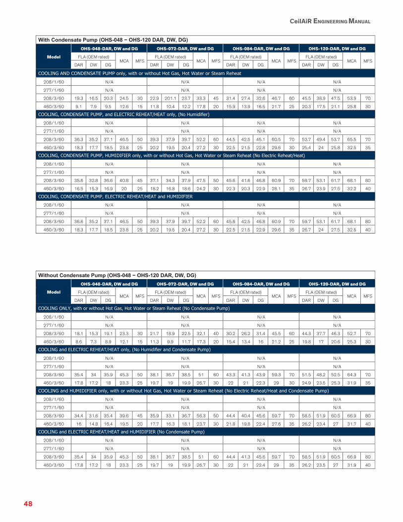
48
CeilAiR ENGINEERING MANUAL
With Condensate Pump (OHS-048 − OHS-120 DAR, DW, DG)
Model
OHS-048-DAR, DW and DG OHS-072-DAR, DW and DG OHS-084-DAR, DW and DG OHS-120-DAR, DW and DG
FLA (OEM rated) MCA
MFS
FLA (OEM rated) MCA
MFS
FLA (OEM rated) MCA
MFS
FLA (OEM rated) MCA
MFS
DAR DW DG DAR DW DG DAR DW DG DAR DW DG
COOLING AND CONDENSATE PUMP only, with or without Hot Gas, Hot Water or Steam Reheat
208/1/60 N/A N/A N/A N/A
277/1/60 N/A N/A N/A N/A
208/3/60 19.3 16.5 20.3 24.5 30 22.9 201.1 23.7 33.3 45 31.4 27.4 32.6 46.7 60 45.5 38.9 47.5 53.9 70
460/3/60 9.1 7.9 9.5 12.6 15 11.8 10.4 12.2 17.8 20 15.9 13.9 16.5 21.7 25 20.3 17.5 21.1 25.8 30
COOLING, CONDENSATE PUMP, and ELECTRIC REHEAT/HEAT only, (No Humidifier)
208/1/60 N/A N/A N/A N/A
277/1/60 N/A N/A N/A N/A
208/3/60 36.3 35.2 37.1 46.5 50 39.3 37.9 39.7 52.2 60 44.5 42.5 45.1 60.5 70 52.7 49.4 53.7 65.5 70
460/3/60 18.3 17.7 18.5 23.8 25 20.2 19.5 20.4 27.2 30 22.5 21.5 22.8 29.6 30 25.4 24 25.8 32.5 35
COOLING, CONDENSATE PUMP, HUMIDIFIER only, with or without Hot Gas, Hot Water or Steam Reheat (No Electric Reheat/Heat)
208/1/60 N/A N/A N/A N/A
277/1/60 N/A N/A N/A N/A
208/3/60 35.6 32.8 36.6 40.8 45 37.1 34.3 37.9 47.5 50 45.6 41.6 46.8 60.9 70 59.7 53.1 61.7 68.1 80
460/3/60 16.5 15.3 16.9 20 25 18.2 16.8 18.6 24.2 30 22.3 20.3 22.9 28.1 35 26.7 23.9 27.5 32.2 40
COOLING, CONDENSATE PUMP, ELECTRIC REHEAT/HEAT and HUMIDIFIER
208/1/60 N/A N/A N/A N/A
277/1/60 N/A N/A N/A N/A
208/3/60 36.6 35.2 37.1 46.5 50 39.3 37.9 39.7 52.2 60 45.6 42.5 46.8 60.9 70 59.7 53.1 61.7 68.1 80
460/3/60 18.3 17.7 18.5 23.8 25 20.2 19.5 20.4 27.2 30 22.5 21.5 22.9 29.6 35 26.7 24 27.5 32.5 40
Without Condensate Pump (OHS-048 − OHS-120 DAR, DW, DG)
Model
OHS-048-DAR, DW and DG OHS-072-DAR, DW and DG OHS-084-DAR, DW and DG OHS-120-DAR, DW and DG
FLA (OEM rated) MCA
MFS
FLA (OEM rated) MCA
MFS
FLA (OEM rated) MCA
MFS
FLA (OEM rated) MCA
MFS
DAR DW DG DAR DW DG DAR DW DG DAR DW DG
COOLING ONLY, with or without Hot Gas, Hot Water or Steam Reheat (No Condensate Pump)
208/1/60 N/A N/A N/A N/A
277/1/60 N/A N/A N/A N/A
208/3/60 18.1 15.3 19.1 23.3 30 21.7 18.9 22.5 32.1 40 30.2 26.2 31.4 45.5 60 44.3 37.7 46.3 52.7 70
460/3/60 8.6 7.3 8.9 12.1 15 11.3 9.9 11.7 17.3 20 15.4 13.4 16 21.2 25 19.8 17 20.6 25.3 30
COOLING and ELECTRIC REHEAT/HEAT only, (No Humidifier and Condensate Pump)
208/1/60 N/A N/A N/A N/A
277/1/60 N/A N/A N/A N/A
208/3/60 35.4 34 35.9 45.3 50 38.1 36.7 38.5 51 60 43.3 41.3 43.9 59.3 70 51.5 48.2 52.5 64.3 70
460/3/60 17.8 17.2 18 23.3 25 19.7 19 19.9 26.7 30 22 21 22.3 29 30 24.9 23.5 25.3 31.9 35
COOLING and HUMIDIFIER only, with or without Hot Gas, Hot Water or Steam Reheat (No Electric Reheat/Heat and Condensate Pump)
208/1/60 N/A N/A N/A N/A
277/1/60 N/A N/A N/A N/A
208/3/60 34.4 31.6 35.4 39.6 45 35.9 33.1 36.7 56.3 50 44.4 40.4 45.6 59.7 70 58.5 51.9 60.5 66.9 80
460/3/60 16 14.8 16.4 19.5 20 17.7 16.3 18.1 23.7 30 21.8 19.8 22.4 27.6 35 26.2 23.4 27 31.7 40
COOLING and ELECTRIC REHEAT/HEAT and HUMIDIFIER (No Condensate Pump)
208/1/60 N/A N/A N/A N/A
277/1/60 N/A N/A N/A N/A
208/3/60 35.4 34 35.9 45.3 50 38.1 36.7 38.5 51 60 44.4 41.3 45.6 59.7 70 58.5 51.9 60.5 66.9 80
460/3/60 17.8 17.2 18 23.3 25 19.7 19 19.9 26.7 30 22 21 22.4 29 35 26.2 23.5 27 31.9 40

49
CeilAiR ENGINEERING MANUAL
With Condensate Pump (OHS-012 − OHS-032 AHU)
Model
OHS-012-AHU OHS-018-AHU OHS-024-AHU OHS-032-AHU
FLA MCA MFS FLA MCA MFS FLA MCA MFS FLA MCA MFS
COOLING AND CONDENSATE PUMP only, with or without Hot Gas, Hot Water or Steam Reheat
208/1/60 3.9 4.9 15 3.9 4.9 15 3.9 4.9 15 4.6 5.8 15
277/1/60 3 3.8 15 3 3.8 15 3 3.8 15 3.5 4.4 15
208/3/60 3.9 4.9 15 3.9 4.9 15 3.9 4.9 15 4.6 5.8 15
460/3/60 2 2.6 15 2 2.6 15 2 2.6 15 2 2.6 15
COOLING, CONDENSATE PUMP, and ELECTRIC REHEAT/HEAT only, (No Humidifier)
208/1/60 25.3 31.6 35 25.3 31.6 35 25.3 31.6 35 26 32.5 35
277/1/60 21.1 26.4 30 21.1 26.4 30 21.1 26.4 30 21.6 27 30
208/3/60 16.3 20.4 25 16.3 20.4 25 16.3 20.4 25 17 21.3 25
460/3/60 8.3 10.4 15 8.3 10.4 15 8.3 10.4 15 8.3 10.4 15
COOLING, CONDENSATE PUMP, and HUMIDIFIER only, with or without Hot Gas, Hot Water or Steam Reheat (No Electric Reheat/Heat)
208/1/60 12.1 15.1 20 12.1 15.1 20 12.1 15.1 20 12.8 16 20
277/1/60 9.1 11.4 15 9.1 11.4 15 9.1 11.4 15 9.6 12 15
208/3/60 12.1 15.1 20 12.1 15.1 20 12.1 15.1 20 12.8 16 20
460/3/60 5.7 7.2 15 5.7 7.2 15 5.7 7.2 15 5.7 7.2 15
COOLING, CONDENSATE PUMP, ELECTRIC REHEAT/HEAT and HUMIDIFIER
208/1/60 33.5 41.9 45 33.5 41.9 45 33.5 41.9 45 34.2 42.8 45
277/1/60 27.2 34 35 27.2 34 35 27.2 34 35 27.7 34.6 35
208/3/60 24.5 30.6 35 24.5 30.6 35 24.5 30.6 35 25.2 31.5 35
460/3/60 12 15.1 20 12 15.1 20 12 15.1 20 12 15.1 20
Without Condensate Pump (OHS-012 − OHS-032 AHU)
Model OHS-012-AHU OHS-018-AHU OHS-024-AHU OHS-032-AHU
FLA MCA MFS FLA MCA MFS FLA MCA MFS FLA MCA MFS
COOLING ONLY, with or without Hot Gas, Hot Water or Steam Reheat (No Condensate Pump)
208/1/60 2.7 3.4 15 2.7 3.4 15 2.7 3.4 15 3.4 4.3 15
277/1/60 1.8 2.3 15 1.8 2.3 15 1.8 2.3 15 2.3 2.9 15
208/3/60 2.7 3.4 15 2.7 3.4 15 2.7 3.4 15 3.4 4.3 15
460/3/60 1.5 1.9 15 1.5 1.9 15 1.5 1.9 15 1.5 1.9 15
COOLING and ELECTRIC REHEAT/HEAT only, (No Humidifier and Condensate Pump)
208/1/60 24.1 30.1 35 24.1 30.1 35 24.1 30.1 35 24.8 31 35
277/1/60 19.9 24.9 25 19.9 24.9 25 19.9 24.9 25 20.4 25.5 30
208/3/60 15.1 18.9 20 15.1 18.9 20 15.1 18.9 20 15.8 19.8 20
460/3/60 7.8 9.8 15 7.8 9.8 15 7.8 9.8 15 7.8 9.8 15
COOLING and HUMIDIFIER only, with or without Hot Gas, Hot Water or Steam Reheat (No Electric Reheat/Heat and Condensate Pump)
208/1/60 10.9 13.6 15 10.9 13.6 15 10.9 13.6 15 11.6 14.5 15
277/1/60 7.9 9.9 15 7.9 9.9 15 7.9 9.9 15 8.4 10.5 15
208/3/60 10.9 13.6 15 10.9 13.6 15 10.9 13.6 15 11.6 14.5 15
460/3/60 5.2 6.5 15 5.2 6.5 15 5.2 6.5 15 5.2 6.5 15
COOLING with ELECTRIC REHEAT/HEAT and HUMIDIFIER (No Condensate Pump)
208/1/60 32.3 40.4 45 32.3 40.4 45 32.3 40.4 45 33 41.3 45
277/1/60 26 32.5 35 26 32.5 35 26 32.5 35 26.5 33.1 35
208/3/60 23.3 29.1 30 23.3 29.1 30 23.3 29.1 30 24 30 35
460/3/60 11.5 14.4 15 11.5 14.4 15 11.5 14.4 15 11.5 14.4 15

50
CeilAiR ENGINEERING MANUAL
With Condensate Pump (OHS-040 − OHS-060 AHU)
Model OHS-040-AHU OHS-048-AHU OHS-060-AHU
FLA MCA MFS FLA MCA MFS FLA MCA MFS
COOLING AND CONDENSATE PUMP only, with or without Hot Gas, Hot Water or Steam Reheat
208/1/60 5.9 7.4 15 N/A N/A
277/1/60 4.6 5.8 15 N/A N/A
208/3/60 5.9 7.4 15 5.1 6.4 15 6.3 7.9 15
460/3/60 2.7 3.4 15 2.6 3.3 15 3.4 4.3 15
COOLING, CONDENSATE PUMP, and ELECTRIC REHEAT/HEAT only, (No Humidifier)
208/1/60 27.3 34.1 35 N/A N/A
277/1/60 22.7 28.4 30 N/A N/A
208/3/60 18.3 22.9 25 29.8 37.3 40 31 38.8 40
460/3/60 9 11.3 15 15.2 19.1 20 16 20.1 25
COOLING, CONDENSATE PUMP, and HUMIDIFIER only, with or without Hot Gas, Hot Water or Steam Reheat (No Electric Reheat/Heat)
208/1/60 14.1 17.6 20 N/A N/A
277/1/60 10.7 13.4 15 N/A N/A
208/3/60 14.1 17.6 20 21.4 26.8 30 22.6 28.3 30
460/3/60 6.4 8.1 15 10 12.6 15 10.8 13.6 15
COOLING, CONDENSATE PUMP, ELECTRIC REHEAT/HEAT and HUMIDIFIER
208/1/60 35.5 44.4 45 N/A N/A
277/1/60 28.8 36 40 N/A N/A
208/3/60 26.5 33.1 35 46.1 57.6 60 47.3 59.1 60
460/3/60 12.7 15.9 20 22.6 28.3 30 23.4 29.3 30
Without Condensate Pump (OHS-040 − OHS-060 AHU)
Model OHS-040-AHU OHS-048-AHU OHS-060-AHU
FLA MCA MFS FLA MCA MFS FLA MCA MFS
COOLING ONLY, with or without Hot Gas, Hot Water or Steam Reheat (No Condensate Pump)
208/1/60 4.7 5.9 15 N/A N/A
277/1/60 3.4 4.3 15 N/A N/A
208/3/60 4.7 5.9 15 3.9 4.9 15 5.1 6.4 15
460/3/60 2.1 2.6 15 2.2 2.8 15 2.9 3.6 15
COOLING and ELECTRIC REHEAT/HEAT only, (No Humidifier and Condensate Pump)
208/1/60 26.1 32.6 35 N/A N/A
277/1/60 21.5 26.9 30 N/A N/A
208/3/60 17.1 21.4 25 28.6 35.8 40 29.8 37.3 40
460/3/60 8.4 10.5 15 14.8 18.5 20 15.5 19.4 20
COOLING and HUMIDIFIER only, with or without Hot Gas, Hot Water or Steam Reheat (No Electric Reheat/Heat and Condensate Pump)
208/1/60 12.9 16.1 20 N/A N/A
277/1/60 9.5 11.9 15 N/A N/A
208/3/60 12.9 16.1 20 20.2 25.2 30 21.4 26.8 30
460/3/60 5.8 7.3 15 9.6 12 15 10.3 12.9 15
COOLING with ELECTRIC REHEAT/HEAT and HUMIDIFIER (No Condensate Pump)
208/1/60 34.3 42.9 45 N/A N/A
277/1/60 27.6 34.5 35 N/A N/A
208/3/60 25.3 31.6 35 44.9 56.1 60 46.1 57.6 60
460/3/60 12.1 15.1 20 22.2 27.8 30 22.9 28.6 30

51
CeilAiR ENGINEERING MANUAL
With Condensate Pump (OHS-048 − OHS-120 DAHU)
Model
OHS-048-DAHU OHS-072-DAHU OHS-084-DAHU OHS-120-DAHU
FLA MCA MFS FLA MCA MFS FLA MCA MFS FLA MCA MFS
COOLING AND CONDENSATE PUMP only, with or without Hot Gas, Hot Water or Steam Reheat
208/1/60 N/A N/A N/A N/A
277/1/60 N/A N/A N/A N/A
208/3/60 4.5 5.6 15 6.3 7.9 15 8.2 10.3 15 10.5 13.1 15
460/3/60 2.3 2.9 15 3.4 4.3 15 3.9 4.9 15 5.3 6.7 15
COOLING, CONDENSATE PUMP, and ELECTRIC REHEAT/HEAT only, (No Humidifier) 208/1/60 N/A N/A N/A N/A
277/1/60 N/A N/A N/A N/A
208/3/60 29.2 36.5 40 31 38.8 40 32.9 41.1 45 35.2 44 45
460/3/60 14.9 18.6 20 16 20.1 25 16.5 20.7 25 17.9 22.4 25
COOLING, CONDENSATE PUMP, and HUMIDIFIER only, with or without Hot Gas, Hot Water or Steam Reheat (No Electric Reheat/Heat) 208/1/60 N/A N/A N/A N/A
277/1/60 N/A N/A N/A N/A
208/3/60 20.8 26 30 20.5 25.6 30 22.4 28 30 24.7 30.9 35
460/3/60 9.7 12.1 15 9.8 12.3 15 10.3 12.9 15 11.7 14.7 15
COOLING, CONDENSATE PUMP, ELECTRIC REHEAT/HEAT and HUMIDIFIER 208/1/60 N/A N/A N/A N/A
277/1/60 N/A N/A N/A N/A
208/3/60 45.5 56.9 60 45.2 56.5 60 47.1 58.9 60 49.4 61.8 70
460/3/60 22.3 27.9 30 22.4 28.1 30 22.9 28.7 30 24.3 30.4 35
Without Condensate Pump (OHS-048 − OHS-120 DAHU)
Model OHS-048-DAHU OHS-072-DAHU OHS-084-DAHU OHS-120-DAHU
FLA MCA MFS FLA MCA MFS FLA MCA MFS FLA MCA MFS
COOLING ONLY, with or without Hot Gas, Hot Water or Steam Reheat (No Condensate Pump)
208/1/60 N/A N/A N/A N/A
277/1/60 N/A N/A N/A N/A
208/3/60 3.3 4.1 15 5.1 6.4 15 7 8.8 15 9.3 11.6 20
460/3/60 1.8 2.2 15 2.9 3.6 15 3.4 4.3 15 4.8 6 15
COOLING and ELECTRIC REHEAT/HEAT only, (No Humidifier and Condensate Pump
208/1/60 N/A N/A N/A N/A
277/1/60 N/A N/A N/A N/A
208/3/60 28 35 40 29.8 37.3 40 31.7 39.6 40 34 42.5 45
460/3/60 14.4 17.9 20 15.5 19.4 20 16 20 25 17.4 21.8 25
COOLING and HUMIDIFIER only, with or without Hot Gas, Hot Water or Steam Reheat (No Electric Reheat/Heat and Condensate Pump)
208/1/60 N/A N/A N/A N/A
277/1/60 N/A N/A N/A N/A
208/3/60 19.6 24.5 25 19.3 24.1 25 21.2 26.5 30 23.5 29.4 30
460/3/60 9.1 11.4 15 9.3 11.6 15 9.8 12.3 15 11.2 14 15
COOLING with ELECTRIC REHEAT/HEAT and HUMIDIFIER (No Condensate Pump)
208/1/60 N/A N/A N/A N/A
277/1/60 N/A N/A N/A N/A
208/3/60 44.3 55.4 60 44 55 60 45.9 57.4 60 48.2 60.3 70
460/3/60 21.8 27.2 30 21.9 27.4 30 22.4 28 30 23.8 29.8 30

52
CeilAiR ENGINEERING MANUAL
DX Free Cooling and Alternate Water Source
-
With Condensate Pump (OHS-012 − OHS-024 HAR, HW, HG)
Model
OHS-012-HAR, HW and HG - AWS or FC
OHS-018-HAR, HW and HG - AWS or FC
OHS-024-HAR, HW and HG - AWS or FC
FLA (OEM rated) MCA
MFS
FLA (OEM rated) MCA
MFS
FLA (OEM rated) MCA
MFS
HAR HW HG HAR HW HG HAR HW HG
COOLING AND CONDENSATE PUMP only, with or without Hot Gas, Hot Water or Steam Reheat 208/1/60 10.3 8.9 10.7 15.8 25 11.3 9.6 11.8 16.8 25 14.9 12.3 15.8 23 35
277/1/60 9.4 8.4 9.7 14.9 20 9.4 8.1 9.8 14.4 20 11.9 10 12.5 18.8 30
208/3/60 N/A N/A 11.2 9.8 11.7 14.9 20
460/3/60 N/A N/A 5.2 4.6 5.4 7.6 15
COOLING, CONDENSATE PUMP, and ELECTRIC REHEAT/HEAT only, (No Humidifier) 208/1/60 31.7 30.3 32.1 42.6 45 32.7 31 33.2 43.5 45 36.3 33.7 37.2 49.8 50
277/1/60 27.5 26.5 27.8 37.5 40 27.5 26.2 27.9 36.8 40 30 28.1 30.6 41.5 45
208/3/60 N/A N/A 23.6 22.2 24.1 30.4 35
460/3/60 N/A N/A 11.5 10.9 11.7 15.5 20
COOLING, CONDENSATE PUMP, and HUMIDIFIER only, with or without Hot Gas, Hot Water or Steam Reheat (No Electric Reheat/Heat) 208/1/60 18.5 17.1 18.9 24 30 19.5 17.8 20 25 35 23.1 20.5 24 31.3 45
277/1/60 15.5 14.5 15.8 21 25 15.5 14.2 15.9 20.3 25 18 16.1 18.6 24.9 35
208/3/60 N/A N/A 19.4 18 19.9 23.1 30
460/3/60 N/A N/A 8.9 8.3 9.1 11.3 15
COOLING, CONDENSATE PUMP, ELECTRIC REHEAT/HEAT and HUMIDIFIER 208/1/60 31.7 30.3 32.1 42.6 45 32.7 31 33.2 43.5 45 36.3 33.7 37.2 49.8 50
277/1/60 27.5 26.5 27.8 37.5 40 27.5 26.2 27.9 36.8 40 30 28.1 30.6 41.5 45
208/3/60 N/A N/A 23.6 22.2 24.1 30.4 35
460/3/60 N/A N/A 11.5 10.9 11.7 15.5 20
Without Condensate Pump (OHS-012 − OHS-024 HAR, HW, HG)
Model
OHS-012-HAR, HW and HG - AWS or FC
OHS-018-HAR, HW and HG - AWS or FC
OHS-024-HAR, HW and HG - AWS or FC
FLA (OEM rated) MCA
MFS
FLA (OEM rated) MCA
MFS
FLA (OEM rated) MCA
MFS
HAR HW HG HAR HW HG HAR HW HG
COOLING ONLY, with or without Hot Gas, Hot Water or Steam Reheat (No Condensate Pump) 208/1/60 9.1 7.7 9.5 14.6 20 10.1 8.4 10.6 15.6 25 13.7 11.1 14.6 21.9 35
277/1/60 8.2 7.2 8.5 13.7 20 8.2 6.9 8.6 13 20 10.7 8.8 11.3 17.6 25
208/3/60 N/A N/A 10 8.6 10.5 13.7 20
460/3/60 N/A N/A 4.7 4.1 4.9 7 15
COOLING and ELECTRIC REHEAT/HEAT only, (No Humidifier and Condensate Pump) 208/1/60 30.5 29.1 30.9 41.4 45 31.5 29.8 32 42.3 45 35.1 32.5 36 48.6 50
277/1/60 26.3 25.3 26.6 36.3 40 26.3 25 26.7 35.7 40 28.8 26.9 29.4 40.3 45
208/3/60 N/A N/A 22.4 21 22.9 29.2 35
460/3/60 N/A N/A 11 10.4 11.2 14.9 15
COOLING and HUMIDIFIER only, with or without Hot Gas, Hot Water or Steam Reheat (No Electric Reheat/Heat and Condensate Pump) 208/1/60 17.3 15.9 17.7 22.8 30 18.3 16.6 18.8 23.8 30 21.9 19.3 22.8 30 45
277/1/60 14.3 13.3 14.4 19.8 25 14.3 13 14.7 19.1 25 16.8 14.9 17.4 23.7 35
208/3/60 N/A N/A 18.2 16.8 18.7 21.9 30
460/3/60 N/A N/A 8.4 7.8 8.6 10.8 15
COOLING with ELECTRIC REHEAT/HEAT and HUMIDIFIER (No Condensate Pump) 208/1/60 30.5 29.1 30.9 41.4 45 31.5 29.9 32 42.3 45 35.1 32.5 36 48.6 50
277/1/60 26.3 25.3 26.6 36.3 40 26.3 25 26.7 35.7 40 28.8 26.9 29.4 40.3 45
208/3/60 N/A N/A 22.4 21 22.9 29.2 35
460/3/60 N/A N/A 11 10.4 11.2 14.9 15

53
CeilAiR ENGINEERING MANUAL
-
With Condensate Pump (OHS-032 − OHS-060 HAR, HW, HG)
Model
OHS-032-HAR, HW and HG - AWS or FC
OHS-040-HAR, HW and HG - AWS or FC
OHS-048-AR, W and G - AWS or FC
OHS-060 AR, W and G - AWS or FC
FLA (OEM rated) MCA
MFS
FLA (OEM rated) MCA
MFS
FLA (OEM rated) MCA
MFS
FLA (OEM rated) MCA
MFS
HAR HW HG HAR HW HG AR W G AR W G
COOLING AND CONDENSATE PUMP only, with or without Hot Gas, Hot Water or Steam Reheat 208/1/60 18.6 15.9 19.4 27.7 40 18.6 15.9 19.4 27.7 40 N/A N/A
277/1/60 15.8 13.5 16.5 23.1 35 15.8 13.5 16.5 23.1 35 N/A N/A
208/3/60 13.4 12 13.8 20.1 30 13.4 12 13.8 20.1 30 19.3 16.8 20.1 27.7 40 25.7 22.4 26.7 32.3 50
460/3/60 6.8 6.1 7 10.6 15 6.8 6.1 7 10.6 15 9.9 8.7 10.3 13.3 20 11.4 10 11.8 15.3 20
COOLING, CONDENSATE PUMP, and ELECTRIC REHEAT/HEAT only, (No Humidifier) 208/1/60 40 37.3 40.8 54.4 60 40 37.3 40.8 54.4 60 N/A N/A
277/1/60 33.9 31.6 34.6 45.7 50 33.9 31.6 34.6 45.7 50 N/A N/A
208/3/60 25.8 24.4 26.2 35.6 40 25.8 24.4 26.2 35.6 40 44 41.5 44.8 58.6 60 50.4 47.1 51.4 63.2 70
460/3/60 13.1 12.4 13.3 18.5 20 13.1 12.4 13.3 18.5 20 22.5 21.3 22.9 29.1 30 24 22.6 24.4 31.1 35
COOLING, CONDENSATE PUMP, and HUMIDIFIER only, with or without Hot Gas, Hot Water or Steam Reheat (No Electric Reheat/Heat) 208/1/60 26.8 24.1 27.6 35.9 50 26.8 24.1 27.6 35.9 50 N/A N/A
277/1/60 21.9 19.6 22.6 29.2 40 21.9 19.6 22.6 29.2 40 N/A N/A
208/3/60 21.6 20.2 22 28.3 40 21.6 20.2 22 28.3 40 35.6 33.1 36.4 44 60 42 38.7 43 48.6 60
460/3/60 10.5 9.8 10.7 14.3 20 10.5 9.8 10.7 14.3 20 17.3 16.1 17.7 20.7 25 18.8 17.4 19.2 22.7 30
COOLING, CONDENSATE PUMP, ELECTRIC REHEAT/HEAT and HUMIDIFIER 208/1/60 40 37.3 40.8 54.4 60 40 37.3 40.8 54.4 60 N/A N/A
277/1/60 33.9 31.6 34.6 45.7 50 33.9 31.6 34.6 45.7 50 N/A N/A
208/3/60 25.8 24.4 26.2 35.6 40 25.8 24.4 26.2 35.6 40 44 41.5 44.8 58.6 60 50.4 47.1 51.4 63.2 70
460/3/60 13.1 12.4 13.3 18.5 20 13.1 12.4 13.3 18.5 20 22.5 21.3 22.9 29.1 30 24 22.6 24.4 31.1 35
Without Condensate Pump (OHS-032 − OHS-060 HAR, HW, HG)
Model
OHS-032-HAR, HW and HG - AWS or FC
OHS-040-HAR, HW and HG - AWS or FC
OHS-048-AR, W and G - AWS or FC
OHS-060 AR, W and G - AWS or FC
FLA (OEM rated) MCA
MFS
FLA (OEM rated) MCA
MFS
FLA (OEM rated) MCA
MFS
FLA (OEM rated) MCA
MFS
HAR HW HG HAR HW HG AR W G AR W G
COOLING ONLY, with or without Hot Gas, Hot Water or Steam Reheat (No Condensate Pump) 208/1/60 17.4 14.7 18.1 26.5 40 17.4 14.7 18.2 26.5 40 N/A N/A
277/1/60 14.6 12.3 15.3 21.9 35 14.6 12.3 15.3 21.9 35 N/A N/A
208/3/60 12.2 10.8 12.6 18.9 30 12.2 10.8 12.6 18.9 30 18.1 15.6 18.9 26.5 40 24.5 21.2 25.5 31.1 50
460/3/60 6.3 5.6 6.5 10.1 15 6.3 5.6 6.5 10.1 15 9.4 8.2 9.8 12.8 20 10.9 9.5 11.3 14.8 20
COOLING and ELECTRIC REHEAT/HEAT only, (No Humidifier and Condensate Pump) 208/1/60 38.8 36.1 39.6 53.2 60 38.8 36.1 39.6 53.2 60 N/A N/A
277/1/60 32.7 30.4 33.4 44.5 50 32.7 30.4 33.4 44.5 50 N/A N/A
208/3/60 24.6 23.2 25 34.4 40 24.6 23.2 25 34.4 40 42.8 40.3 43.6 57.4 60 49.2 45.9 50.2 62 70
460/3/60 12.6 11.9 12.8 18 20 12.6 11.9 12.8 18 20 22 20.8 22.4 28.5 30 23.5 22.1 23.9 30.5 35
COOLING and HUMIDIFIER only, with or without Hot Gas, Hot Water or Steam Reheat (No Electric Reheat/Heat and Condensate Pump) 208/1/60 25.6 22.9 26.4 34.7 50 25.6 22.9 26.4 34.7 50 N/A N/A
277/1/60 20.7 18.4 21.4 28 40 20.7 18.4 21.4 28 40 N/A N/A
208/3/60 20.4 19 20.8 27.1 35 20.4 19 20.8 27.1 35 34.4 31.9 35.2 42.8 50 40.8 37.5 41.8 47.4 60
460/3/60 10 9.3 10.2 13.8 20 10 9.3 10.2 13.8 20 16.8 15.6 17.2 20.2 25 18.3 16.9 18.7 22.2 30
COOLING with ELECTRIC REHEAT/HEAT and HUMIDIFIER (No Condensate Pump) 208/1/60 38.8 36.1 39.6 53.2 60 38.8 36.1 39.6 53.2 60 N/A N/A
277/1/60 32.7 30.4 33.4 44.5 50 32.7 30.4 33.4 44.5 50 N/A N/A
208/3/60 24.6 23.2 25 34.4 40 24.6 23.2 25 34.4 40 42.8 40.3 43.6 57.4 60 49.2 45.9 50.2 62 70
460/3/60 12.6 11.9 12.8 18 20 12.6 11.9 12.8 18 20 22 20.8 22.4 28.5 30 23.5 22.1 23.9 30.5 35
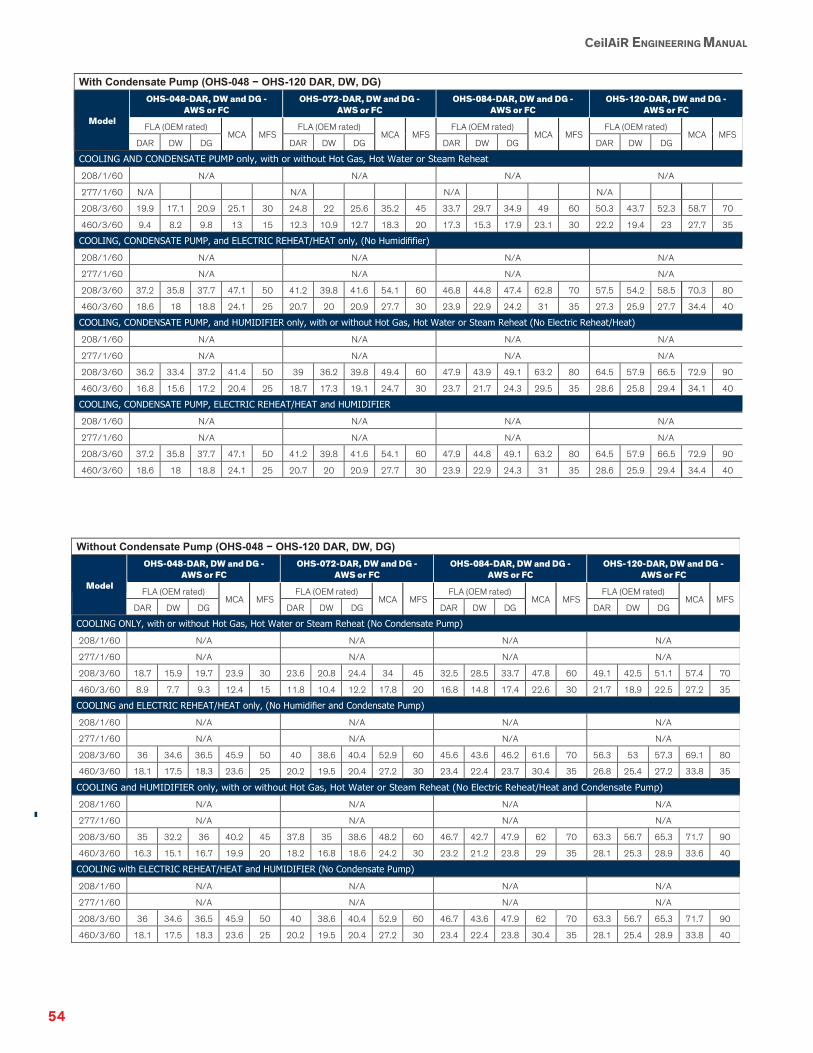
54
CeilAiR ENGINEERING MANUAL
-
With Condensate Pump (OHS-048 − OHS-120 DAR, DW, DG)
Model
OHS-048-DAR, DW and DG - AWS or FC
OHS-072-DAR, DW and DG - AWS or FC
OHS-084-DAR, DW and DG - AWS or FC
OHS-120-DAR, DW and DG - AWS or FC
FLA (OEM rated) MCA
MFS
FLA (OEM rated) MCA
MFS
FLA (OEM rated) MCA
MFS
FLA (OEM rated) MCA
MFS
DAR DW DG DAR DW DG DAR DW DG DAR DW DG
COOLING AND CONDENSATE PUMP only, with or without Hot Gas, Hot Water or Steam Reheat 208/1/60 N/A N/A N/A N/A
277/1/60 N/A N/A N/A N/A
208/3/60 19.9 17.1 20.9 25.1 30 24.8 22 25.6 35.2 45 33.7 29.7 34.9 49 60 50.3 43.7 52.3 58.7 70
460/3/60 9.4 8.2 9.8 13 15 12.3 10.9 12.7 18.3 20 17.3 15.3 17.9 23.1 30 22.2 19.4 23 27.7 35
COOLING, CONDENSATE PUMP, and ELECTRIC REHEAT/HEAT only, (No Humidififier) 208/1/60 N/A N/A N/A N/A
277/1/60 N/A N/A N/A N/A
208/3/60 37.2 35.8 37.7 47.1 50 41.2 39.8 41.6 54.1 60 46.8 44.8 47.4 62.8 70 57.5 54.2 58.5 70.3 80
460/3/60 18.6 18 18.8 24.1 25 20.7 20 20.9 27.7 30 23.9 22.9 24.2 31 35 27.3 25.9 27.7 34.4 40
COOLING, CONDENSATE PUMP, and HUMIDIFIER only, with or without Hot Gas, Hot Water or Steam Reheat (No Electric Reheat/Heat) 208/1/60 N/A N/A N/A N/A
277/1/60 N/A N/A N/A N/A
208/3/60 36.2 33.4 37.2 41.4 50 39 36.2 39.8 49.4 60 47.9 43.9 49.1 63.2 80 64.5 57.9 66.5 72.9 90
460/3/60 16.8 15.6 17.2 20.4 25 18.7 17.3 19.1 24.7 30 23.7 21.7 24.3 29.5 35 28.6 25.8 29.4 34.1 40
COOLING, CONDENSATE PUMP, ELECTRIC REHEAT/HEAT and HUMIDIFIER 208/1/60 N/A N/A N/A N/A
277/1/60 N/A N/A N/A N/A
208/3/60 37.2 35.8 37.7 47.1 50 41.2 39.8 41.6 54.1 60 47.9 44.8 49.1 63.2 80 64.5 57.9 66.5 72.9 90
460/3/60 18.6 18 18.8 24.1 25 20.7 20 20.9 27.7 30 23.9 22.9 24.3 31 35 28.6 25.9 29.4 34.4 40
Without Condensate Pump (OHS-048 − OHS-120 DAR, DW, DG)
Model
OHS-048-DAR, DW and DG - AWS or FC
OHS-072-DAR, DW and DG - AWS or FC
OHS-084-DAR, DW and DG - AWS or FC
OHS-120-DAR, DW and DG - AWS or FC
FLA (OEM rated) MCA
MFS
FLA (OEM rated) MCA
MFS
FLA (OEM rated) MCA
MFS
FLA (OEM rated) MCA
MFS
DAR DW DG DAR DW DG DAR DW DG DAR DW DG
COOLING ONLY, with or without Hot Gas, Hot Water or Steam Reheat (No Condensate Pump) 208/1/60 N/A N/A N/A N/A
277/1/60 N/A N/A N/A N/A
208/3/60 18.7 15.9 19.7 23.9 30 23.6 20.8 24.4 34 45 32.5 28.5 33.7 47.8 60 49.1 42.5 51.1 57.4 70
460/3/60 8.9 7.7 9.3 12.4 15 11.8 10.4 12.2 17.8 20 16.8 14.8 17.4 22.6 30 21.7 18.9 22.5 27.2 35
COOLING and ELECTRIC REHEAT/HEAT only, (No Humidifier and Condensate Pump) 208/1/60 N/A N/A N/A N/A
277/1/60 N/A N/A N/A N/A
208/3/60 36 34.6 36.5 45.9 50 40 38.6 40.4 52.9 60 45.6 43.6 46.2 61.6 70 56.3 53 57.3 69.1 80
460/3/60 18.1 17.5 18.3 23.6 25 20.2 19.5 20.4 27.2 30 23.4 22.4 23.7 30.4 35 26.8 25.4 27.2 33.8 35
COOLING and HUMIDIFIER only, with or without Hot Gas, Hot Water or Steam Reheat (No Electric Reheat/Heat and Condensate Pump) 208/1/60 N/A N/A N/A N/A
277/1/60 N/A N/A N/A N/A
208/3/60 35 32.2 36 40.2 45 37.8 35 38.6 48.2 60 46.7 42.7 47.9 62 70 63.3 56.7 65.3 71.7 90
460/3/60 16.3 15.1 16.7 19.9 20 18.2 16.8 18.6 24.2 30 23.2 21.2 23.8 29 35 28.1 25.3 28.9 33.6 40
COOLING with ELECTRIC REHEAT/HEAT and HUMIDIFIER (No Condensate Pump)
208/1/60 N/A N/A N/A N/A
277/1/60 N/A N/A N/A N/A
208/3/60 36 34.6 36.5 45.9 50 40 38.6 40.4 52.9 60 46.7 43.6 47.9 62 70 63.3 56.7 65.3 71.7 90
460/3/60 18.1 17.5 18.3 23.6 25 20.2 19.5 20.4 27.2 30 23.4 22.4 23.8 30.4 35 28.1 25.4 28.9 33.8 40

55
CeilAiR ENGINEERING MANUAL
Chilled Water
With Condensate Pump (OHS-012 − OHS-040 C)
Model
OHS-012-C OHS-018-C OHS-024-C OHS-032-C OHS-040-C
FLA MCA MFS FLA MCA MFS FLA MCA MFS FLA MCA MFS FLA MCA MFS
COOLING AND CONDENSATE PUMP only, with or without Hot Gas, Hot Water or Steam Reheat
208/1/60 3.9 4.9 15 3.9 4.9 15 3.9 4.9 15 4.6 5.8 15 5.9 7.4 15
277/1/60 3 3.8 15 3 3.8 15 3 3.8 15 3.5 4.4 15 4.6 5.8 15
208/3/60 3.9 4.9 15 3.9 4.9 15 3.9 4.9 15 4.6 5.8 15 5.9 7.4 15
460/3/60 2 2.6 15 2 2.6 15 2 2.6 15 2 2.6 15 2.7 3.4 15
COOLING, CONDENSATE PUMP, and ELECTRIC REHEAT/HEAT only, (No Humidifier)
208/1/60 25.3 31.6 35 25.3 31.6 35 25.3 31.6 35 26 32.5 35 27.3 34.1 35
277/1/60 21.1 36.4 30 21.1 36.4 30 21.1 36.4 30 21.6 27 30 22.7 28.4 30
208/3/60 16.3 20.4 25 16.3 20.4 25 16.3 20.4 25 17 21.3 25 18.3 22.9 25
460/3/60 8.3 10.4 15 8.3 10.4 15 8.3 10.4 15 8.3 10.4 15 9 11.3 15
COOLING, CONDENSATE PUMP, and HUMIDIFIER only, with or without Hot Gas, Hot Water or Steam Reheat (No Electric Reheat/Heat)
208/1/60 12.1 15.1 20 12.1 15.1 20 12.1 15.1 20 12.8 16 20 14.1 17.6 20
277/1/60 9.1 11.4 15 9.1 11.4 15 9.1 11.4 15 9.6 12 15 10.7 13.4 15
208/3/60 12.1 15.1 20 12.1 15.1 20 12.1 15.1 20 12.8 16 20 14.1 17.6 20
460/3/60 5.7 7.2 15 5.7 7.2 15 5.7 7.2 15 5.7 7.2 15 6.4 8.1 15
COOLING, CONDENSATE PUMP, ELECTRIC REHEAT/HEAT and HUMIDIFIER
208/1/60 33.5 41.9 45 33.5 41.9 45 33.5 41.9 45 34.2 42.8 45 35.5 44.4 45
277/1/60 27.2 34 35 27.2 34 35 27.2 34 35 27.7 34.6 35 28.8 36 40
208/3/60 24.5 30.6 35 24.5 30.6 35 24.5 30.6 35 25.2 31.5 35 26.5 33.1 35
460/3/60 12 15.1 20 12 15.1 20 12 15.1 20 12 15.1 20 12.7 15.9 20
Without Condensate Pump (OHS-012 − OHS-040 C)
Model OHS-012-C OHS-018-C OHS-024-C OHS-032-C OHS-040-C
FLA MCA MFS FLA MCA MFS FLA MCA MFS FLA MCA MFS FLA MCA MFS
COOLING ONLY, with or without Hot Gas, Hot Water or Steam Reheat (No Condensate Pump)
208/1/60 2.7 3.4 15 2.7 3.4 15 2.7 3.4 15 3.4 4.3 15 4.7 5.9 15
277/1/60 1.8 2.3 15 1.8 2.3 15 1.8 2.3 15 2.3 2.9 15 3.4 4.3 15
208/3/60 2.7 3.4 15 2.7 3.4 15 2.7 3.4 15 3.4 4.3 15 4.7 5.9 15
460/3/60 1.5 1.9 15 1.5 1.9 15 1.5 1.9 15 1.5 1.9 15 2.2 2.8 15
COOLING and ELECTRIC REHEAT/HEAT only, (No Humidifier and Condensate Pump)
208/1/60 24.1 30.1 35 24.1 30.1 35 24.1 30.1 35 24.8 31 35 26.1 32.6 35
277/1/60 19.9 24.9 25 19.9 24.9 25 19.9 24.9 25 20.4 25.5 30 21.5 26.9 30
208/3/60 15.1 18.9 20 15.1 18.9 20 15.1 18.9 20 15.8 19.8 20 17.1 21.4 25
460/3/60 7.8 9.8 15 7.8 9.8 15 7.8 9.8 15 7.8 9.8 15 8.5 10.6 15
COOLING and HUMIDIFIER only, with or without Hot Gas, Hot Water or Steam Reheat (No Electric Reheat/Heat and Condensate Pump)
208/1/60 10.9 13.6 15 10.9 13.6 15 10.9 13.6 15 11.6 14.5 15 12.9 16.1 20
277/1/60 7.9 9.9 15 7.9 9.9 15 7.9 9.9 15 8.4 10.5 15 9.5 11.9 15
208/3/60 10.9 13.6 15 10.9 13.6 15 10.9 13.6 15 11.6 14.5 15 12.9 16.1 20
460/3/60 5.2 6.5 15 5.2 6.5 15 5.2 6.5 15 5.2 6.5 15 5.9 7.4 15
COOLING with ELECTRIC REHEAT/HEAT and HUMIDIFIER (No Condensate Pump)
208/1/60 32.3 40.4 45 32.3 40.4 45 32.3 40.4 45 33 41.3 45 34.3 42.9 45
277/1/60 26 32.5 35 26 32.5 35 26 32.5 35 26.5 33.1 35 27.6 34.5 35
208/3/60 23.3 29.1 30 23.3 29.1 30 23.3 29.1 30 24 30 35 25.3 31.6 35
460/3/60 11.5 14.4 15 11.5 14.4 15 11.5 14.4 15 11.5 14.4 15 12.2 15.3 20
-

56
CeilAiR ENGINEERING MANUAL
With Condensate Pump (OHS-048 − OHS-120 C)
Model OHS-048-C OHS-060-C OHS-072-C OHS-084-C OHS-120-C
FLA MCA MFS FLA MCA MFS FLA MCA MFS FLA MCA MFS FLA MCA MFS
COOLING AND CONDENSATE PUMP only, with or without Hot Gas, Hot Water or Steam Reheat
208/1/60 N/A N/A N/A N/A N/A
277/1/60 N/A N/A N/A N/A N/A
208/3/60 5.1 6.4 15 6.3 7.9 15 6.3 7.9 15 8.2 10.3 15 10.5 13.1 20
460/3/60 2.6 3.3 15 3.4 4.3 15 3.4 4.3 15 3.9 4.9 15 5.3 6.7 15
COOLING, CONDENSATE PUMP, and ELECTRIC REHEAT/HEAT only, (No Humidifier)
208/1/60 N/A N/A N/A N/A N/A
277/1/60 N/A N/A N/A N/A N/A
208/3/60 29.8 37.3 40 31 38.8 40 31 38.8 40 32.9 41.1 45 35.2 44 45
460/3/60 15.2 19.1 20 16 20.1 25 16 20.1 25 16.5 20.7 25 17.9 22.4 25
COOLING, CONDENSATE PUMP, and HUMIDIFIER only, with or without Hot Gas, Hot Water or Steam Reheat (No Electric Reheat/Heat)
208/1/60 N/A N/A N/A N/A N/A
277/1/60 N/A N/A N/A N/A N/A
208/3/60 21.4 26.8 30 22.6 28.3 30 20.5 25.6 30 22.4 28 30 24.7 30.9 35
460/3/60 10 12.6 15 10.8 13.6 15 9.8 12.3 15 10.3 12.9 15 11.7 14.7 15
COOLING, CONDENSATE PUMP, ELECTRIC REHEAT/HEAT and HUMIDIFIER
208/1/60 N/A N/A N/A N/A N/A
277/1/60 N/A N/A N/A N/A N/A
208/3/60 46.1 57.6 60 47.3 59.1 60 45.2 56.5 60 47.1 58.9 60 49.4 61.8 70
460/3/60 22.6 28.3 30 23.4 29.3 30 22.4 28.1 30 22.9 28.7 30 24.3 30.4 35
Without Condensate Pump (OHS-048 − OHS-120 C)
Model OHS-048-C OHS-060-C OHS-072-C OHS-084-C OHS-120-C
FLA MCA MFS FLA MCA MFS FLA MCA MFS FLA MCA MFS FLA MCA MFS
COOLING ONLY, with or without Hot Gas, Hot Water or Steam Reheat (No Condensate Pump)
208/1/60 N/A N/A N/A N/A N/A
277/1/60 N/A N/A N/A N/A N/A
208/3/60 3.9 4.9 15 5.1 6.4 15 5.1 6.4 15 7 8.8 15 9.3 11.6 20
460/3/60 2.1 2.6 15 2.9 3.6 15 2.9 3.6 15 3.4 4.3 15 4.8 6 15
COOLING and ELECTRIC REHEAT/HEAT only, (No Humidifier and Condensate Pump)
208/1/60 N/A N/A N/A N/A N/A
277/1/60 N/A N/A N/A N/A N/A
208/3/60 28.6 35.8 40 29.8 37.3 40 29.8 37.3 40 31.7 39.6 40 34 42.5 45
460/3/60 14.7 18.4 20 15.5 19.4 20 15.5 19.4 20 16 20 25 17.4 21.8 25
COOLING and HUMIDIFIER only, with or without Hot Gas, Hot Water or Steam Reheat (No Electric Reheat/Heat and Condensate Pump)
208/1/60 N/A N/A N/A N/A N/A
277/1/60 N/A N/A N/A N/A N/A
208/3/60 20.2 25.2 30 21.4 26.8 30 19.3 24.1 25 21.2 26.5 30 23.5 29.4 30
460/3/60 9.5 11.9 15 10.3 12.9 15 9.3 11.6 15 9.8 12.3 15 11.2 14 15
COOLING with ELECTRIC REHEAT/HEAT and HUMIDIFIER (No Condensate Pump)
208/1/60 N/A N/A N/A N/A N/A
277/1/60 N/A N/A N/A N/A N/A
208/3/60 44.9 56.1 60 46.1 57.6 60 44 55 60 45.9 57.4 60 48.2 60.3 70
460/3/60 22.1 27.6 30 22.9 28.6 30 21.9 27.4 30 22.4 28 30 23.8 29.8 30

57
CeilAiR ENGINEERING MANUAL
Dimensional Data and Installation Drawings
The sections that follow present the following information:
• Unit Net Weights (lbs) Table
• Refrigerant Connection Sizes Table
• Air Cooled Systems Dimensional Drawings
• DX Air Handling Units Dimensional Drawings
• Water / Glycol Cooled Systems Dimensional Drawings
• Chilled Water Systems Dimensional Drawings

58
CeilAiR ENGINEERING MANUAL
Unit Net Weights (lb)
Physical Data and Connection Sizes
(Cooling Only. Please see notes, given in lb.)
OHS-( )-( ) 012 018 024 032 040 048 060 072 084 120
OHS-( )-AS 210 215 220 255 265 - - - - -
OHS-( )-AR 160 165 170 205 215 370 380 - - -
OHS-( )-HAR 185 190 195 230 240 - - - - -
OHS-( )-AHU 120 120 120 155 165 270 280 - - -
OHS-( )-HAHU 135 140 145 180 190 - - - - -
OHS-( )-DAR - - - - - 420 - 450 510 580
OHS-( )-DAHU - - - - - 320 - 350 410 480
OHS-( )-W 180 200 210 245 260 395 405 - - -
OHS-( )-HW 205 225 235 265 285 - - - - -
OHS-( )-DW - - - - - 440 - 470 550 625
OHS-( )-G 180 200 210 245 260 395 405 - - -
OHS-( )-HG 205 225 235 265 285 - - - - -
OHS-( )-DG - - - - - 440 - 470 550 625
OHS-( )-C 120 125 125 160 170 280 290 365 415 495
OHS-( )-HC 140 145 150 185 190 - - - - -
OHS-( )-( )-FC 245 265 275 300 310 500 510 570 660 745
OHS-( )-( )-AWS 225 230 235 270 280 460 470 550 610 705
Table Legend:
Note-1: Hyphen (‘-’) value means indicated unit not available in the indicated capac- ity/configuration.
Note-2: Unit net weights shown above are for Cooling Only Evaporator units without receivers. If Humidity Options (steam humidifier; electric, hot gas, hot water or steam reheat) and/or -30 °F flooded receiver(s) are applicable, please add the approximate weights shown in the Model Sizes table on this page to the unit net weights.
Model Sizes
Features/Options 012/040 048/060 048/120-D( )
Adding Features: Net Additions
Steam Humidifier + 20 lb + 25 lb + 25 lb
Electric Reheat + 15 lb + 25 lb + 25 lb Hot Gas Reheat + 30 lb + 35 lb + 45 lb Hot Water Reheat + 30 lb + 35 lb + 45 lb Steam Reheat + 30 lb + 35 lb + 45 lb
-30 °F Flooded + 30 lb + 50 lb + 100 lb Condensate Pump + 10 lb + 10 lb + 10 lb (Figures may vary if receiver skid is used)

59
CeilAiR ENGINEERING MANUAL
Refrigerant Piping Connection Sizes
Refrigerant Piping Connection Sizes - Single Compressor / Circuit Systems
Model OHS-012-( ) OHS-018-( ) OHS-024-( ) OHS-032-( ) OHS-040-( ) OHS-048-( ) OHS-060-( )
“A” “B” “C” “A” “B” “C” “A” “B” “C” “A” “B” “C” “A” “B” “C” “A” “B” “C” “A” “B” “C”
OHS-( )-AR ---- 3/8 1/2 ---- 3/8 1/2 ---- 3/8 5/8 ---- 1/2 5/8 ---- 1/2 7/8 ---- 1/2 7/8 ---- 1/2 7/8
OHS-( )-AHU 5/8 3/8 ---- 3/4 3/8 ---- 3/4 3/8 ---- 3/4 1/2 ---- 7/8 1/2 ---- 7/8 1/2 ---- 7/8 1/2 ----
Refrigerant Piping Connection Sizes -
Dual Compressor / Circuit Systems Sizes given are per circuit O.D.
Model OHS-048-( ) OHS-072-( ) OHS-084-( ) OHS-120-( )
“A” “B” “C” “A” “B' “C” “A” “B” “C” “A” “B” “C”
OHS-( )-DAR ---- 3/8 5/8 ---- 1/2 5/8 ---- 1/2 7/8 ---- 1/2 7/8
OHS-( )-DAHU 3/4 3/8 ---- 7/8 1/2 ---- 7/8 1/2 ---- 7/8 1/2 ----
Legend:
“A” = Suction Line, inches OD Copper “B” = Liquid Line, inches OD Copper “C” = Hot Gas, inches OD Copper
Notes:
Note-1:-------- means connection type not applicable to this unit configuration.
Note-2: Dimensions shown represent the “pipe connection size” only. For information detailing the sizing of the interconnecting refrigerant and water lines, please refer to the CeilAiR Installation, Operation and Maintenance Manual.
Source Water/Glycol Connection Sizes
Source Water / Glycol Piping Connection Sizes (Single Compressor / Single Circuit Systems)
Model 012 018 024 032 040 048 060
IN/OUT IN/OUT IN/OUT IN/OUT IN/OUT IN/OUT IN/OUT
OHS-( )-W/G 5/8 7/8 7/8 7/8 7/8 1-1/8 1-1/8
OHS-( )-W/G-FC 5/8 5/8 5/8 7/8 7/8 1-1/8 1-1/8
Chilled Water / Alternate Water Source Piping Connection Sizes
Model 012 018 024 032 040 048 060
IN/OUT IN/OUT IN/OUT IN/OUT IN/OUT IN/OUT IN/OUT
OHS-( )-C and AWS 5/8 7/8 7/8 7/8 7/8 1-1/8 1-1/8
Model 048 072 084 120
IN/OUT IN/OUT IN/OUT IN/OUT
OHS-( )-C and AWS. 1-1/8 1-1/8 1-1/8 1-3/8
Legend:
IN = Inlet Connection, inches OD Copper OUT = Outlet Connection, inches OD Copper

60
CeilAiR ENGINEERING MANUAL
Air Cooled Systems
Air Cooled (“Ductless” Spot Cooler)
OHS-012 thru 032-AS Self-Con- tained, Air Cooled (“Ducted” Evap
- Direct Driven)
OHS-012 thru 032-AS Self-Contained, Air Cooled
(“Ductless” Spot Cooler) DIMENSIONAL DATA (in.)
MODEL “A” “B” “C” “D”
OHS-012, 018,and 024-AS 20.38 15.5 5.50 18.0
OHS-032-AS 26.38 21.5 10.50 23.0
DIMENSIONAL DATA (in.)
MODEL “A” “B” “C” “D” “E” “F”
OHS-012, 018,and 024-AS 20.38 15.5 5.75 18.0 19.75 16.13
OHS-032-AS 26.38 21.5 10.88 23.0 15.63 19.75

61
CeilAiR ENGINEERING MANUAL
OHS-040-HAS Self-Contained, Air Cooled (“Ducted” Version - Direct
Driven)
OHS-012 thru 032-AR Remote Air Cooled, Evaporator (“Ducted”
Version - Direct Driven)
OHS-012 thru 032-AR Remote Air Cooled, Evaporator (“Ductless”
Spot Cooler)
DIMENSIONAL DATA (in.)
MODEL “A”
OHS-012, 018,and 024-AR. 20.38
OHS-032-AR 26.38
DIMENSIONAL DATA (in.)
MODEL “A” “B” “E” “F”
OHS-012, 018 and 024-AR 20.38 15.5 19.75 16.13
OHS-032-AR 26.38 21.5 15.63 19.75

62
CeilAiR ENGINEERING MANUAL
OHS-048 thru 060-AR Remote Air Cooled, Evaporator (Ducted
Only)
Note: Consult your local Sales Represen- tative for blower outlet dimensional data for “High-Static Pressure Blower Option”.
DIMENSIONAL DATA (in.)
MODEL “C” “L” “M”
OHS-040 and 060-AR 6.62 11.38 13.12
OHS-040-AR Remote Air Cooled, Evaporator (“Ductless” Spot Cooler)
OHS-012 thru 040-HAR Remote Air Cooled, Evaporator “H-Series Ducted Ver- sion” (040 - Direct Driven) and (012/040
- Belt Driven)
DIMENSIONAL DATA (in.)
MODEL “A” “B” “C” “L” “M”
OHS-012, 018, and 024-HAR 20.0 16.0
see note
see note
see note
OHS-032- and 040-HAR 24.0 20.0 see note
see note
see note
OHS-040-HAR, @ 0.3 in. ESP (direct drive blower) 24.0 20.0 6.62 11.38 10.5

63
CeilAiR ENGINEERING MANUAL
DIMENSIONAL DATA (in.)
MODEL “C” “L” “M”
OHS-120-DAR 7.25 13.44 15.62
OHS-048 thru 084-DAR Remote Air Cooled, Evaporator (DUAL Compressors)
DIMENSIONAL DATA (in.)
MODEL “C” “L” “M”
OHS-048-DAR 6.62 11.38 13.12
OHS-072 and 084-DAR 7.62 13.44 15.62
OHS-120-DAR Remote Air Cooled, Evaporator (DUAL Compressors)

64
CeilAiR ENGINEERING MANUAL
DX Air Handling Units
Note: Consult your local Sales Repre- sentative for blower outlet dimensional data for “High-Static Pressure Blower Option”.
OHS-012 thru 040-HAHU DX - “H-Series”, Air Handling Unit (“Ducted
Version” - Belt Driven)
OHS-012 thru 040-AHU DX - Air Handling Unit (“Ducted Version” -
Direct Driven)
OHS-012 thru 040-AHU DX - Air Handling Unit (“Ductless” Spot
Cooler)
DIMENSIONAL DATA (in.)
MODEL “A” “B” “E” “F”
OHS-012, 018, and 024-AHU 20.7 15.5 19.88 15.75
OHS-032 and 040-AHU 26.7 21.5 15.75 19.88
DIMENSIONAL DATA (in.)
MODEL “A” “E” “F” “C” “L” “M”
OHS-012, 018, and 024-AHU 20.0 19.75 15.63 see note
see note
see note
OHS-032 and 040-AHU 24.0 19.75 19.75 see note
see note
see note
DIMENSIONAL DATA (in.)
MODEL “A”
OHS-012, 018, and 024-AHU 20.7
OHS-032 and 040-AR 26.7

65
CeilAiR ENGINEERING MANUAL
DIMENSIONAL DATA (in.)
Model “C” “L” “M”
OHS-048-DAHU 6.62 11.38 13.12
OHS-072 and 084-AHU 7.62 13.44 15.62
DIMENSIONAL DATA (in.)
MODEL Std ft3/min @ 0.5” ESP
“C” “L” “M”
OHS-120-DAHU 7.38 13.5 15.69
OHS-048 thru 060-AHU DX - Air Handling Unit (Ducted Only)
DIMENSIONAL DATA (in.)
MODEL “C” “L” “M”
OHS-048 and 060-AHU 6.62 11.38 13.12
OHS-120-DAHU DUAL Circuit, DX - Air Handling Unit (Ducted Only)
OHS-048 thru 084-DAHU DUAL Circuit, DX - Air Handling Unit (Ducted
Only)

66
CeilAiR ENGINEERING MANUAL
Water/Glycol Systems
DIMENSIONAL DATA (in.)
MODEL “A” “B” “E” “F”
OHS-012, 018 and 024-W/G 20.4 15.5 19.75 16.13
OHS-032-W/G 26.4 21.5 15.63 19.75
OHS-012 thru 032-W / G Self-Con- tained, Water/Glycol Cooled (“Duct-
less” Spot Cooler)
OHS-040-W / G Self-Contained, Water/Glycol Cooled (“Ductless”
Spot Cooler)
OHS-012 thru 032-W / G Self-Con- tained, Water/Glycol Cooled (“Ducted
Version” - Direct Drive)
DIMENSIONAL DATA (in.)
MODEL “A”
OHS-012, 018 and 024 W/G 20.4
OHS-032-W/G 26.4

67
CeilAiR ENGINEERING MANUAL
Note: Consult your local Sales Representative for blower outlet dimensional data for “High-Static Pressure Blower Option”.
Note: Consult your local Sales Representative for blower outlet dimensional data for “High-Static Pressure Blower Option”.
OHS-012 thru 040-HW / HG and optional OHS-012 thru 040-HW/HG-FC “H-Series Ducted Version” (040 - Direct Driven) and
(012/040 - Belt Driven)
DIMENSIONAL DATA (in.)
MODEL “A” “B” “C” “L” “M”
OHS-012, 018, and 024- HW/HG (and HW/HG-FC) 20.0 16.0
see note
see note
see note
OHS-032, and 040-HW/HG (and HW/HG-FC)
24.0 20.0 see note
see note
see note
OHS-040-HW/G @ 0.3” ESP (Direct-Drive Blower)
24.0 20.0 6.62 11.38 10.5
OHS-048 thru 060-W / G and optional OHS-048 thru 060-W/G- FC Self-Contained, Water/Glycol
Cooled (Ducted Only)
DIMENSIONAL DATA (in.)
MODEL “C” “L” “M”
OHS-048 and 060-W/G 6.62 11.38 13.12
OHS-048 and 060-W/G-FC see note
see note see note

68
CeilAiR ENGINEERING MANUAL
Note: Consult your local Sales Represen- tative for blower outlet dimensional data for “High-Static Pressure Blower Option”.
DIMENSIONAL DATA (in.)
MODEL “C” “L” “M”
OHS-120-DW/DG 7.25 13.5 15.69
OHS-048 thru 084-DW / DG and optional W/DG-FC Self-Contained, Water/ Glycol
Cooled (DUAL Compressors)
DIMENSIONAL DATA (in.)
MODEL “C” “L” “M”
OHS-048-DW/DG 6.62” 11.38” 13.19”
OHS-072-084-DW/DG 7.62” 13.5” 15.69”
OHS-048/084-DW/DG-FC see note see note see note
OHS-120-DW / DG Self-Contained, Water/Glycol Cooled (DUAL Compressors)

69
CeilAiR ENGINEERING MANUAL
OHS-120-DW / DG-FC “FREE-COOLING Version”
Self-Contained, Water/Glycol Cooled (DUAL Compressors)
DIMENSIONAL DATA (in.)
MODEL “C” “L” “M”
OHS-120-DW/DG-FC 7.62 13.5 15.69

70
CeilAiR ENGINEERING MANUAL
OHS-012 thru 040-C Chilled Water System (“Ductless” Spot
Cooler)
Chilled Water Systems
Note: Consult your local Sales Represen- tative for blower outlet dimensional data for “High-Static Pressure Blower Option”.
OHS-012 thru 040-HC “H-Series”, Chilled Water System (“Ducted
Version” - Belt Driven)
OHS-012 thru 040-C Chilled Water System (“Ducted Version” - Direct
Driven)
DIMENSIONAL DATA (in.)
MODEL “A”
OHS-012-, 018, and 024-C, in. 20.7
OHS-032 and 040-C, in. 26.7
DIMENSIONAL DATA (in.)
MODEL “A” “B” “E” “F”
OHS-012, 018, and 024-C 20.4 15.5 19.75 15.63
OHS-032, and 040-C 26.4 21.5 15.63 19.75
DIMENSIONAL DATA (in.)
MODEL “A” “E” “F” “C” “L” “M”
OHS-012, 018, and 024-HC 20.0 19.75 15.63 SEE
NOTE SEE
NOTE SEE
NOTE
OHS-032 and 040-HC 24.0 19.75 19.75 SEE
NOTE SEE
NOTE SEE
NOTE

71
CeilAiR ENGINEERING MANUAL
OHS-048 thru 060-C Chilled Water System (“Ducted” - Belt
Driven)
DIMENSIONAL DATA (in.)
MODEL “C” “L” “M”
OHS-048 and 060-C 6.62 11.38 13.12
OHS-120-C Chilled Water System (“Ducted” - Belt Driven)
OHS-072 thru 084-C Chilled Water System (“Ducted” - Belt Driven)
DIMENSIONAL DATA (in.)
MODEL “C” “L” “M”
OHS-072 and 084-C 7.62 13.5 15.69
DIMENSIONAL DATA (in.)
MODEL “C” “L” “M”
OHS-120-C 7.38 13.5 15.7

72
CeilAiR ENGINEERING MANUAL
STULZ CeilAiR Series 3.5 – 35 kW Single/Dual Circuit Ceiling Mounted Precision Air Conditioners Summary This specification describes requirements for a precision environmental control system. The STULZ CeilAiR ceiling-mounted air conditioning system shall provide precision temperature and/or humidity control for computer rooms or rooms containing communications or other highly sensitive heat load equipment where continuous 24 hour a day, 365 days a year air conditioning is required. The units are designed with a wide range of options to handle all precision cooling applications.
Design Requirements The system shall be a ceiling mounted supplemental air conditioner. The air conditioner shall be fully accessible in-place through easily removable side access panels.
Quality Assurance
The manufacturer shall maintain a set of international standards of quality management to ensure product quality. Prior to shipment each system shall be subject to a complete operational and functional testing based on predefined procedures. The air conditioner manufacturer shall be ISO 9001:2015 certified.
Cabinet The cabinet and access panels shall be fabricated from aluminum for corrosion protection and to minimize the system’s weight. The panels shall be lined with 2 lb/ft2 high density sound and thermal insulation and sealed with self-extinguishing gasketing conforming to NFPA 90A and 90B.
Air Flow Patterns “Ductless” Spot Cooler (Models OHS-012 thru 040-( ) only) The air conditioner shall be designed for installation in a standard 2 ft x 4 ft ceiling grid for ductless supply and return evaporator air through a factory provided bottom supply and return filter grille.
Ducted Evaporator (Available on all model sizes) The air conditioner shall be provided with evaporator supply and return air duct connections.
Air Filtration The air conditioning unit shall have a drop out, 1 in. deep, Class 2 (per UL Standard 900) filter easily accessed through the hinged return grille. The filter shall have a rating of at least 80% average arrestance as measured by ASHRAE Standard 52-76 test method.
Mechanical Components
Blowers/Motors Direct Drive Systems The blower shall be direct driven with double width, double inlet housing and forward curved blades. The blower shall be dynamically and statically balanced to minimize vibration and operate in the Class I range.
The evaporator motor shall be factory wired for the correct speed to produce the specified air quantity. The motor shall have internal overload protection.
Belt Driven Systems The blower shall be belt driven with a double width, double inlet housing and forward curved blades and permanently lubricated ball bearings sized for an average 100,000 hours of service life. The blowers shall be dynamically and statically balanced to minimize vibration and operate in the Class I range. The blower shall have an adjustable base for belt tensioning and a locking system to prevent the motors from moving. Motor drive sheave shall have an adjustable pitch to change the speed of the blower. The motor shall be 1,725 RPM and shall have overload protection and a minimum NEMA service factor of 1.15.
REFRIGERATION SYSTEM All piping and components contained within the refrigeration system shall be rated for use with R407C refrigerant. The refrigeration circuit shall include, as a minimum, a refrigerant dryer/strainer, sight glass with moisture detector, thermal expansion valve, evaporator coil, compressor, high-pressure switch with manual reset, and low-pressure switch with automatic reset.
Scroll Compressor The compressor shall be a high efficiency, high reliability, low noise scroll compressor. The compressor shall be complete with internal vibration isolation, internal thermal overloads, internal pressure relief valve, internal discharge gas vibration eliminator, and external vibration mounting isolation.

73
CeilAiR ENGINEERING MANUAL
Dual Compressor System (Models OHS-( )-D())
The air conditioner shall be a dual scroll compressor system with two independent refrigeration circuits to provide 50% capacity unloading, as well as component redundancy.
The air conditioner shall be provided with a 2-stage temperature controller with microprocessor-based control logic for automatic staging.
Evaporator Coil The evaporator coil shall be constructed of seamless drawn copper tubes, mechanically bonded to tempered aluminum fins with enhanced design for maximum heat transfer and mounted in a sloped stainless-steel condensate drain pan. The coil shall be designed for a maximum of 500 ft/min face velocity.
Air Cooled Heat Rejection
0 °F, Fan Cycling / Fan Speed The air-cooled system shall incorporate a low ambient fan cycling / fan speed head pressure control. The pressure control shall be for year-round air conditioning system operation down to 0 °F DB minimum ambient air temperature.
-20°F Variable Fan Speed Control The air-cooled system shall incorporate a low ambient, variable speed fan, head pressure control. The pressure control shall be for year-round air conditioning system operation down to -20°F DB minimum ambient air temperature.
-30°F Flooded Control The air-cooled system shall incorporate a low ambient flooded head pressure control. The pressure control shall be for year-round system operation down to -30°F DB minimum ambient air temperature. Liquid refrigerant receivers with receiver liquid sight glass and head pressure regulator valves (for flooded condenser operation) shall be included.
Water/Glycol Cooled Heat Rejection Heat Exchanger
Each evaporator refrigerant circuit shall be provided with a factory-installed single pass, counterflow configured, tube-in- tube coaxial condenser designed and tested for 450 psi wwp.
2-Way, 150 psig Regulating Valve (Standard) Each refrigerant circuit’s head pressure shall be controlled by a factory-installed 2-way water / glycol regulating valve rated for 150 psi wwp.
DX Water Cooled and Glycol Cooled systems are available with following standard and optional head pressure regulating control valves: 2-way,150 psig (Standard) 2-way, 350, 400 psig (Optional) 3-way, 150, 350, 400 psig (Optional)
Free-Cooling Systems (Optional) DX Water/Glycol Cooled systems with Free-Cooling shall be provided with the following standard DX head pressure and Free-Cooling valve combination:
DX Valves – 3-way, 150 psig FC Valve – 3-way, 300 psig
Alternate Water Source Systems (Optional) The alternate water source cooling shall be controlled by the following standard and optional control valves:
2- way, 150 psig (Standard) 3- way, 350 psig (Optional) 3- way, 400 psig (Optional)
A 2/3-way modulating AWS cooling control valve shall be factory installed. Precision cooling control shall be accomplished via an analog control signal to the proportionally actuating control valve.
Chilled Water Systems Chilled Water Cooling Coil The coil shall be constructed of seamless drawn copper tubes, mechanically bonded to tempered aluminum fins with enhanced fin design for maximum heat transfer and mounted in a sloped stainless-steel condensate drain pan. The coil shall be designed for a maximum of 500 ft./min. face velocity. The water circuit shall be designed to distribute water into the entire coil face area. Manual air bleed vents and drain ports shall be factory installed.
Chilled Water Control Valve Cooling capacity shall be controlled by a factory-installed slowly opening and slowly closing 2-way motorized control valve rated for a maximum 300 psi wwp.
Overflow Safety Float Switch A condensate pan water level switch shall be incorporated to shut the system down if a condensate overflow condition is sensed.
Remote Start/Stop Included in the system’s electrical control circuit shall be a 2-pin terminal connection for remote start/stop of the CeilAiR air conditioner by remote source.
Electrical System The electrical system shall conform to National Electrical Code requirements. The control circuit shall be 24 volts AC, wire in accordance with NEC Class II requirements. The control circuit wire shall not be smaller than 18 AWG. All wiring shall be neatly wrapped and routed in bundles. Each wire shall end with a service loop and be securely fastened by an approved method. Each wire in the unit shall be numbered for ease of service tracing.

74
CeilAiR ENGINEERING MANUAL
All electrically actuated components shall be easily accessible from the front of the unit without reaching over exposed high voltage components or rotating parts. Each high voltage circuit shall be individually protected by circuit breakers or manual motor starters on all phases. The blower motor shall have thermal and short circuit protection. Line voltage and 24-volt control circuit wiring shall be routed in separate bundles.
The electric box shall be positioned for service convenience and shall include all the contactors, starters, fuses, circuit breakers, terminal boards and control transformer required for operation of the STULZ unit and shall allow for full service access.
Controller A-Tech-1.1 Controller The CeilAiR ceiling air conditioner shall be provided with a STULZ slim-line, ultra-thin profile, 1-stage cool / 1-stage heat, remote wall mounted programmable digital microprocessor based controller.
Notes:
• The A-Tech-1.1 thermostat is standard on all single stage DX and non-proportional chilled water systems.
• The A-Tech-1.2 thermostat is standard on all dual stage DX systems.
• A remote sensor (wired) is available on request.
A-Tech-1.1 Features:
• Auto changeover for Heat/Cool Modes • Selectable °F or °C display • Fan selector for continuous fan operation • Built-in short cycle protection • Internal switch to lock-out the keypad to prevent unauthorized
tampering • Electronic calibration • 45 second fan purge after heating and cooling call • Day/Night button for user selectable alternate setpoint
manual setback
E² Series Controller General The advanced microprocessor-based E² Series controller shall be equipped with flexible software capable of meeting the specific needs of the application. The setpoints shall be default and their ranges shall be easily viewed and adjusted from the user interface display. The program and operating parameters shall be permanently stored on a non-volatile system in the event of power failure.
The controller shall be designed to manage temperature and relative humidity (RH) levels to a user defined setpoint via control output signals to the system.
The controller shall receive inputs for measurable control conditions (temperature, relative humidity, and dew point) via return air or room mounted sensors. The internal logic will then determine if the conditions require cooling, humidification or dehumidification. Control setpoints shall be established to maintain design conditions of the installation. The controller will respond accordingly to changes in these conditions and control the output/demand for the appropriate mode of operation until user defined conditions are achieved.
Field Configurable The program for the E² Series controller shall be field configurable, so the operator can select control setpoints specific to the application. The operator interface for the E² controller is provided via a door mounted user interface
display panel. The display panel shall be a backlit LCD graphical display and function keys that give complete control and monitoring capability of the precision cooling system. The menu-driven interface shall provide the ability to scroll through and enter various menu screens.
Password Protection Access to the Info Menu, Alarms Log, and the ability to monitor room conditions shall be allowed without the use of a password. Modifications to the control setpoints shall require the use of a password. The controller shall be programmed to recognize predetermined security levels before allowing access to display screens containing critical variables. Three secured menu levels (Control, Service and Factory) will support unique passwords that must be entered to access the menu screens so only authorized personnel may perform modifications to the settings.
Restorable Parameters/Factory Defaults Upon initial start-up the system shall operate using the setpoints programmed by the factory. The customer may enter new operating parameters in the Control menu and the system will then operate accordingly. The new setpoints may be stored as, “Customer Default Setpoints”. The primary setpoints entered by the factory remain stored in the controller’s memory as, “Factory Setpoints”. The setpoints for the system may be re- adjusted in the Control menu at any time. If it becomes necessary, the customer may restore the setpoints back to the Customer Default setpoint values or to the original Factory (primary) setpoint values.

75
CeilAiR ENGINEERING MANUAL
Timer Feature The timer shall enable a setup of an operating schedule to automatically scale back or shut down the air conditioner during low demand or unoccupied periods. This is an energy saving feature to create an operating schedule tailored to the needs of the building. An evening (night-setback) schedule may also be created to enable the system to operate at night with relaxed temperature/humidity setpoints and offsets.
A/C Grouping pLAN Operation (Optional) Multiple STULZ CeilAiR system controllers shall be able to be connected (grouped) to a pLAN local network, allowing the communication of data and information from each controller to a central control terminal or Lead controller. The Lead controller display screens can be used to monitor and adjust group control variables for the individual system controllers. Each E² controller connected to the pLAN network shall be identified with its own unique address. Multiple STULZ CeilAiR systems consisting of up to eight STULZ precision air conditioners equipped with like controllers may be controlled and monitored via the E² series controller. With multiple STULZ CeilAiR systems each unit can selectively be configured as Active to operate as a primary A/C, Capacity Assist for staged operation, or as Standby to come online for a failed air conditioning unit to ensure continuous availability. The controller may also be configured to rotate units with timed duty cycling to promote equal run-time and assure that each STULZ CeilAiR system, within the rotating group, is operationally exercised on a periodic timed basis.
Remote BMS Interface (Optional) The E² series controller shall incorporate a communication interface port that can be field connected to a Building Management System via Modbus, BACnet MS/TP, SNMP, HTTP, or BACnet over ETHERNET/IP as configured by the factory. A controller interfaced to a network must be configured for BMS communication.
Alarms Alarm conditions shall activate a red LED indicator that backlights the alarm function key. As an option, an alarm condition may also be enunciated by an audible alarm signal. An alarm is acknowledged by pressing the alarm key. This calls up alarm display screens that provides a text message detailing the alarm conditions. After an alarm condition is corrected, the alarm can be cleared by pressing the alarm key.
E² Constant Contact (Optional) The control package shall include a STULZ Constant Contact short-term power supply for the E² Series Controller to allow the controller to manage the power transfer switch from one primary power source to another while maintaining communications with an active monitoring system. The E² Constant Contact shall permit a minimum of one-minute ride through period.
Optional Features STULZ CeilAiR standard features can be deleted and/or substituted with optional features to allow you the flexibility to select the configuration best suited for your application.
Mechanical Options Full-Floating, Hot Gas Bypass (Models OHS-( )-()AHU/RCU-() only)
The CeilAiR ceiling A/C shall incorporate a full floating hot gas bypass system to provide modulation of the unit’s cooling capacity and evaporator coil freeze protection under low load conditions.
Snap-Acting, Hot Gas Bypass (Models OHS-()-AR, W and G only)
The STULZ CeilAiR ceiling mounted air conditioning system shall incorporate a snap-acting hot-gas bypass system to provide modulation of the unit’s cooling capacity and evaporator coil freeze protection under low load conditions.
High Static Pressure Belt-Drive Blowers The CeilAiR ceiling air conditioner shall be provided with a high static pressure belt-driven evaporator blower to provide standard unit airflow.
(Note: Due to the probable change in standard unit blower motor horsepower for the High Static Belt-Drive Blower option, please consult your local STULZ sales representative for the following unit specification changes: Blower Motor Horsepower, Net Cooling Capacity, Electrical Data, Discharge Blower Data
Unit Air Flow Rate (ft3/min) will match values shown in the Performance Data tables for each respective unit model.)
Low Entering Condenser Water Kit For Water/Glycol systems that require entering condenser water temperatures from 45°F to 65°F, the system provides a factory installed in-line liquid refrigerant receiver to help reduce the negative effect the low condenser source can have on the evaporator. A compressor crankcase heater is standard with this option. (Compressor Sound Jackets are not available with this option due to the crankcase heater).
Steam Generating Humidifier The humidifier shall be a self-contained atmospheric steam generator. The humidifier assembly shall include an integral fill cup, fill and drain valves, disposable steam cylinder and associated piping. The humidifier shall be equipped with an auto-adaptive control system to optimize water conductivity, control automatic drain and flush cycles, minimize energy waste and maximize cylinder life. The humidifier shall have output between 20% and 100% of rated capacity. The unit shall include draw in water tempering to ensure the drain water does not exceed 140°F during operation.

76
CeilAiR ENGINEERING MANUAL
Dehumidification Cycle DX The system shall be a refrigeration-based dehumidification mode. Moisture is condensed on the cooling coil and discharged through the condensate drain. Reheat (electric, hot gas, steam or hot water) shall be used to offset sensible cooling during the dehumidification cycle.
Dehumidification Cycle CW The system shall be provided with a dehumidification control mode. The chilled water valve shall be opened to allow chilled water flow during a dehumidification demand. Moisture is condensed on the cooling coil and discharged through the condensate drain. Reheat (electric, hot water) shall be provided to offset sensible cooling during the dehumidification cycle.
Electric Reheat/Heat A factory mounted and wired low-watt density, electric resistance heater shall be included to provide automatic sensible reheating during the dehumidification cycle and automatic heating mode. Electric heaters shall be provided with miniature thermal/magnetic circuit breakers that shall protect each ungrounded conductor. Also included will be one automatic reset and one manual reset over-temperature safety device (pilot duty).
Hot Gas Reheat (Models OHS-()-AS, AR, W and G only)
A factory-installed copper tube, aluminum-fin hot gas reheat coil and valve shall be provided for automatic sensible reheating mode during dehumidification cycle is provided. Hot compressor discharge gas shall be diverted from the condenser to the hot gas reheat coil providing energy-free sensible reheating.
Hot Water Reheat/Heat A factory-installed, copper tube, aluminum-fin heat/ reheat coil and 2-way control valve shall be provided to control the flow of hot water for automatic sensible reheating mode during the dehumidification cycle and automatic heating mode as required.
Steam Reheat/Heat A factory installed copper tube, aluminum fin heat/reheat coil and 2-way control valve shall be provided to control the flow of steam for automatic sensible reheating mode during the dehumidification cycle and automatic heating mode as required.
Note: Steam trap and steam piping specialties shall be provided by others, not STULZ
SCR Fired Reheat (Requires E²controller) The electric heat/reheat shall be controlled through a “Zero Firing” Silicon Controlled Rectifier (SCR) with an
extruded aluminum heat sink and solid-state logic system to provide close dry bulb temperature control.
Low Profile Condensate Pump A Low-Profile condensate pump designed for limited height ceiling plenum installation shall be factory provided for automatic removal of condensate and humidifier flush water (if applicable). The condensate pump shall be field installed as a standard. The Low-Profile condensate pump can be factory installed as an option on models OHS-012/040-AS, AHU, AR, W, G and C.
All-Metal Condensate Pump A heavy-duty All-Metal condensate pump shall be provided for automatic removal of condensate and humidifier flush water (if applicable). The pump shall be constructed with a cast aluminum reservoir and impeller; aluminum reservoir cover and impeller chamber cover; stainless steel fasteners and a stainless-steel motor shaft. The condensate pump meets most local codes for certification as a “plenum rated” pump. The condensate pump shall be field installed only. The condensate pump shall be specifically designed to operate with the higher condensate temperatures caused by the flush and drain cycle of the electrode canister humidifiers.
Dual Overflow Safety Switches In addition to the standard condensate pan overflow safety float(s), the condensate pump shall include an internal overflow safety float switch which, when wired to the A/C’s remote stop/ start terminals, shall open the A/C’s control circuit, thereby shutting the A/C down in the event of a condensate overflow.
Air Filtration CeilAiR ceiling A/C’s are available with the following standard (F1) and optional (F2 and F3) high efficiency IAQ-conscious filtration: F1: 1 in., 20% effective filtration (standard) F2:
2 in., 30% effective filtration
F3: 2 in., 30% plus 4 in., 60% for 95% effective filtration (includes field-installed filter box for 4 in. filter)
Air Pattern Type Filters Available
Direct Drive 012/040 w/ Spot Cooler: F1 w/ Ducted Return: F1, F2 (n/a 024)
Belt-Drive Units w/ Ducted Return: F1, F2 and F3
Filter ratings are based on dust spot efficiency ratings per ASHRAE Test Standard 52-76.
Note: F2 and F3 optional filters create additional static pressure and may require the High Static Pressure Belt-Drive Option. Please consult your local Sales Representative for details.

77
CeilAiR ENGINEERING MANUAL
Smoke Detection A photo-electric smoke detector shall be factory installed and wired in the return air section of the STULZ CeilAiR air conditioning system. The photo-electric detector shall include built-in circuitry that performs a functional test of all detection circuits at least once every 40 seconds without the need for generating smoke. The UL-listed velocity range shall be 0-3000 fpm. The air conditioner will shut down upon sensing smoke in the return air stream.
Firestat The STULZ CeilAiR system shall be provided with a factory wired and mounted firestat. The firestat shuts down the air conditioner upon sensing a high return air temperature.
Remote Water Detector-Spot Type A remote single point water/leak detector shall be factory supplied and shall ship separately for field installation. Upon sensing a water leak, the normally closed water detector control circuit shall open, thereby shutting down the STULZ CeilAiR water producing components.
Remote Water Detector-Dual Spot Type A dual remote single point water/leak detector shall be factory supplied and shall ship separately for field installation. Upon sensing a water leak, the normally closed water detector control circuit shall open, thereby shutting down the STULZ CeilAiR water producing components.
Remote Water Detector-Strip Type A 20 ft. remote strip/cable type water/leak detector shall be provided for remote field installation. In addition to the 20 ft. sensing cable, a 24-volt water detector power module shall require field mounting and wiring to the factory provided terminal connection. Upon sensing a water leak, the normally closed water detector control circuit shall open, thereby shutting down the STULZ CeilAiR water producing components.
Compressor Sound Jacket (Air Cooled 0 °F OHS-()-AS and Water/Glycol Cooled Only) The compressor shall be provided with an acoustical sound jacket (shipped loose). Each sound jacket shall have a snap closure system for ease of removing and re-installation during maintenance. The sound jacket shall have a Noise Reduction Coefficient NRC of 85 per ASTM C-423 and a Sound Trans- mission Loss STC of 11 per ASTM E-90.
Electrical Options
Three Phase Power Supply (Available on OHS-024, 032 and 040-() units.) Compressor, (belt-drive blower motor and electric heat/reheat if applicable) shall be three phase in lieu of standard single phase. All other components (5/10 lb humidifier and direct drive motor(s)) shall be single phase, with each leg of power supply balanced as closely as possible.
Note: Three phase power supply is a standard feature on models OHS-048 and larger units.
277/1/60 Power Supply (Models OHS-012 thru-040)
A main power distribution block shall be located in the air conditioner’s electric box for single point power connection to a 277/1/60 power supply source. All system components (motor, heater and humidifier, if applicable) shall be rated for operation with a 277/1/60 power supply. 277V to 208V main power step-down transformers shall not be required.
Fast-delivery orders sometimes require the OHS system be shipped from stock as 208/1/60. In those cases, 277/1/60 applications are provided with a field-installed 277-to-208V step-down transformer.
Main Power Service Switch The main power service switch shall be the NEMA 3R or NEMA-12 non-fused type, depending on the OHS model selected. The disconnect switch shall have a lockable handle.
Field installed main power service switches shall be the standard option, however, switches can be optionally factory mounted on select CeilAiR systems. Factory mounting of disconnect switches is not available on models OHS-012, 018, 024 and 032-AS incorporating the “Ducted” Evaporator Connection option. Air-Side Economizer Controls The STULZ CeilAiR system controller shall be equipped with a unique air-side economization mode for applications using outdoor air-side economizing.
The STULZ Air-Side economizer control package shall include an outdoor temperature and humidity sensor, remote space return air sensor, and supply air sensor for proper control during economizer operation.
Individual discrete analog output signals (0-10 VDC) are available to allow control of the external outdoor air intake damper and exhaust relief provisions. Control settings shall be included for both temperature and humidity properties of the outdoor air. A damper signal lockout shall be included if the outdoor air conditions reaches user adjustable limits.
The economizing damper signal shall allow a minimum output setting for minimum outside air control to meet ventilation requirements.

78
CeilAiR ENGINEERING MANUAL
Alternate Water Source To use building chilled water supply when available as the primary cooling cycle, with compressor, cooling as a backup, an Alternate Water Source cooling cycle is provided.
The air conditioner has two cooling systems:
Primary Mode The primary mode of cooling is a chilled water/glycol circuit with alternate water source cooling coil and 3-way modulating (0-10 Vdc) control valve rated for300 psig. w.w.p. Secondary/Backup Mode The controller microprocessor’s Alternate Water Source program algorithm analyzes input data from factory provided water inlet temperature, and return room air temperature, and relative humidity sensors. Based on this data, the controller automatically controls the sequencing of the primary AWS chilled water to and from the secondary/ backup compressor DX mode of operation. If chilled water is available, the system operates like a chilled water unit, without the compressor operating. When the water temperature is too high, or the water flow rate is not sufficient, the air conditioner automatically switches to the compressor, DX refrigerant cycle.
Code Conformance The supplied system shall be with the following compliance approvals: CETL US listed to UL 1995 (2011 Ed. 4) CSA C22.2 No. 236 (2011 Ed. 4)

79
CeilAiR ENGINEERING MANUAL
North American Headquarters
STULZ Air Technology Systems, Inc. 1572 Tilco Drive | Frederick, MD 21704 301.620.2033 | Fax: 301.662.5487 | [email protected] Technical Support: 888.529.1266
www.stulz-usa.com
QE-OHS0023B- Feb. 2018 © STULZ Air Technology Systems, Inc. - Specifications subject to change without notice.