ceilair ohs series installation, operation & maintenance...
TRANSCRIPT
(©July, 2008)
CeilAiR OHS Series Installation, Operation & Maintenance Manual
Air Technology Systems, Inc.

(©July, 2008)
CeilAiR OHS Series Installation, Operation & Maintenance Manual
Air Technology Systems, Inc.
MODEL NOMENCLATURE
OHS-040-G-FC
OHS = Overhead System
Nominal Capacity in 1,000’s of BTU/Hr
AWS = Alternate Water Source
FC = Free Cooling
LP = Low Profile Configuration
SF = Same-Face Air Pattern
SP = Special Configuration
AHU = Air Handling Unit
AR = Air-Cooled Remote (Split)
AS = Air-Cooled Self-Contained
C = Chilled Water System
CAA = Indoor Centrifugal Condenser
D( ) = Dual (Two) Circuit System
G = Glycol-Cooled
H( ) = Horizontal Discharge (“H-Series”)
RCU-I =Indoor Centrifugal Remote Condensing Unit
W = Water Cooled

(©July, 2008)
CeilAiR OHS Series Installation, Operation & Maintenance Manual
Air Technology Systems, Inc.
1.0 Introduction ............................................ 1-1
1.1 General .................................................... 1-1
1.2 Product Description .................................. 1-1
1.3 Controls ................................................... 1-2
1.4 Product Warranty ..................................... 1-3
1.5 Safety ...................................................... 1-4
1.5.1 General .................................................... 1-4
1.5.2 Safety Summary ...................................... 1-4
1.6. General Design ........................................ 1-6
2.0 Installation ............................................. 2-1
2.1 Receiving the Equipment. ......................... 2-1
2.2 Site Preparation ....................................... 2-1
2.3 Rigging..................................................... 2-1
2.4 Mounting .................................................. 2-2
2.4.1 Indoor Equipment ..................................... 2-2
2.4.2 Outdoor Equipment .................................. 2-2
2.4.3 Controls ................................................... 2-2
2.4.4 Optional Equipment .................................. 2-3
2.4.4.1 Transformer .............................................. 2-3
2.4.4.2 Condensate Pump (Field Inst.) ................. 2-4
2.4.4.3 Non-fused Service Switch ......................... 2-4
2.4.5 Remote Sensors ...................................... 2-4
2.4.5.1 Remote Temperature Sensor .................... 2-4
2.4.5.2 Remote Temperature/Humidity Sensor ..... 2-4
2.4.5.3 Remote Water Detector ........................... 2-4
2.4.5.4 Cable Type Water Detector ...................... 2-4
2.5 Air Distribution Connection ....................... 2-5
2.5.1 Spot Cooler .............................................. 2-5
2.5.2 Ducted Systems ...................................... 2-6
2.6 Piping Connections .................................. 2-6
2.6.1 Refrigerant ............................................... 2-6
2.6.2 Chilled Water and Water/Glycol ............... 2-8
2.6.3 Condensate Drain Line ............................. 2-9
2.6.4 Humidifier (Optional) ................................. 2-9
2.7 Utility Connections ................................. 2-10
2.7.1 Main Power ............................................ 2-10
2.7.2 Controls ................................................. 2-12
2.7.3 Optional Equipment ................................ 2-15
2.7.3.1 Condensate Pump ................................. 2-15
2.7.3.2 Remote Temperature Sensor .................. 2-15
TABLE OF CONTENTS
2.7.3.3 Remote Water Detector ......................... 2-15
2.7.4 Air-Cooled Split Systems ....................... 2-16
2.7.4.1 Remote Condenser ................................ 2-16
2.7.4.2 Remote Condensing Unit ....................... 2-16
2.7.5 Glycol Systems ..................................... 2-16
2.7.6 Remote Shut Down ................................ 2-19
2.8 System Charging Procedures ................. 2-19
2.8.1 R22 Refrigerant Charging Procedures ..... 2-19
2.8.2 R407C Refrigerant Charging Procedures . 2-20
2.9 System Settings & Adjustments ............ 2-19
2.9.1 Low/High Limit Switch ............................ 2-21
2.9.2 Head Pressure Controls- Air Cooled
Systems ................................................ 2-22
2.9.3 Head Pressure Controls- Water/GlycolCooled Systems .................................... 2-23
2.9.4 Humidifier Adjustment ............................ 2-23
2.9.5 Belt Drive Blower .................................... 2-24
2.9.6 Thermal Expansion Valve ....................... 2-24
2.9.7 Hot Gas Reheat ..................................... 2-24
2.9.8 Hot Gas Bypass .................................... 2-24
2.10 Refrigerant Pressure Characteristics ...... 2-26
3.0 Start-Up / Commissioning ..................... 3-1
3.1 Operation ................................................. 3-1
3.2 Step by Step Start-Up Instructions ............ 3-1
3.3 Thermostat Programming ......................... 3-2
3.3.1 A-Tech-1.1 ............................................... 3-2
3.3.2 A-Tech-1.2 ............................................... 3-5
3.3.3 Advanced Microprocessor Controls(Optional) ................................................. 3-7
4.0 Maintenance .......................................... 4-1
4.1 Periodic General Maintenance ................. 4-1
4.1.1 Precision A/C Unit .................................... 4-1
4.1.2 Condensing Unit ....................................... 4-2
4.2 Troubleshooting ........................................ 4-2
4.3 Field Service ............................................ 4-6
4.3.1 Refrigerant Piping ..................................... 4-6
4.3.2 Leak Detection ......................................... 4-6
4.3.3 Leak Repair .............................................. 4-6
4.3.4 General Common Repairs/ComponentReplacement ............................................ 4-6
i

(©July, 2008)
CeilAiR OHS Series Installation, Operation & Maintenance Manual
Air Technology Systems, Inc.
List of Figures
Figure 1 Typical Installation ................................ 2-2
Figure 2 Spot Cooler Grille .................................. 2-5
Figure 3 Ducted System Typical Air Patterns ...... 2-6
Figure 4 Condensate Pump ................................ 2-9
Figure 5 Sample Nameplate ............................. 2-10
Figure 6 Transformer Schematic ........................2-11
Figure 7 A-Tech-1.1 Control Wiring ................... 2-13
Figure 8 A-Tech-1.2 Control Wiring ................... 2-15
TABLE OF CONTENTS (Continued)
ii
4.3.4.1 Compressor Failure .................................. 4-6
4.3.4.2 Standard Cleanout Procedure ................... 4-7
4.3.4.3 Burn-Out/Acidic Cleanup Procedure ......... 4-7
4.3.4.4 Humidifier Cylinder Replacement .............. 4-7
4.3.4.5 Filter Replacement ................................... 4-8
5.0 Product Support Group ......................... 5-1
5.1 Technical Support .................................... 5-1
5.2 Obtaining Warranty Parts ......................... 5-1
5.3 Obtaining Spare/Replacement Parts ......... 5-1
Glycol Systems .................................. 2-18
Figure 13 Belt Drive Blower ................................. 2-24
Figure 14 A-Tech-1.1 Control Panel ...................... 3-2
Figure 15 A-Tech-1.2 Control Panel ...................... 3-5
Appendix A – Forms
Checklist for Completed Installation .........................A-1
Periodic General Maintenance Checksand Service Checklist ...............................................A-2
Appendix B – Glossary
Definition of Terms and Acronyms ............................B-1
List of Figures (Cont.)
Figure 9 Interconnecting Field Wiring RemoteCondenser .......................................... 2-17
Figure 10 Interconnecting Field Wiring Remote Condensing Unit (A-Tech-1.1/1.2) .. 2-17
Figure 11 Interconnecting Field Wiring RemoteCondensing Unit (A-Tech-20) ............... 2-17
Figure 12 Interconnecting Field Wiring
Notice
This document contains information protected by copyright. All rights are reserved. The owner of the equipment forwhich this manual is written may photocopy the contents of this manual for internal use only. No part of this docu-ment may be photocopied, reproduced, or translated into another language for use by anyone other than the ownerof the equipment for which this manual is written without the prior written consent of Stulz Air Technology Systems,Inc. (SATS).
This document contains confidential and proprietary information of Stulz Air Technology Systems, Inc. Distributing orphotocopying this document for external distribution is in direct violation of U.S. copyright laws and is strictlyprohibited without the express written consent of SATS.
Unpublished — rights reserved under the copyright laws of the United States and of other countries.Other brands and tradenames are trademarks of their respective owners.
Copyright 2007 by Stulz Air Technology Systems, Inc.Printed in the United States of America.All rights reserved.
Stulz Air Technology Systems, Inc.1572 Tilco DriveFrederick, MD 21704USA
(©July, 2008)
CeilAiR OHS Series Installation, Operation & Maintenance Manual
Air Technology Systems, Inc.
1.0 Introduction
1.1 General
Thank you for your selection of the CeilAiR ceiling-mounted air conditioning system made by Stulz AirTechnology Systems, Inc.
CeilAiR overhead air conditioning systems (OHS) aredesigned and constructed using the finest availablematerials/components, state-of-the-art technology andquality craftsmanship to provide years of trouble-freeservice. Due to technological advancement, all compo-nents are subject to change without notice.
All CeilAiR OHS systems and CyberAiR® centrifugalcondensers are designed to be installed indoors,unless otherwise noted on the equipment. Propeller-type condensers, condensing units, drycoolers andpump packages are designed for outdoor use.
1.2 Product Description
CeilAiR OHS systems are designed to be the mostversatile and flexible ceiling-mounted air conditioningsystems in the industry. The unit is available in air-cooled, water-cooled, glycol-cooled and chilled-waterconfigurations. The cooling capacity in BTU/Hr willdepend on the unit size, which can range from 1 to 10tons, and can be either a single stage or dual stageunit.
The functional modes of operation, in addition tocooling, are heating, humidification, dehumidificationand filtration, which provide complete environmentalcontrol of a conditioned space. The cabinet configura-tion is available in a 2' x 4' frame for units ranging from12,000 to 40,000 BTU/Hr (spot cooler or ducted) or alarger frame for units ranging from 48,000 to 120,000BTU/Hr (ducted only). There are three basic configu-rations of airflow patterns: 90º/Right Angle, Straight-Thru and In/Out Same-Face.
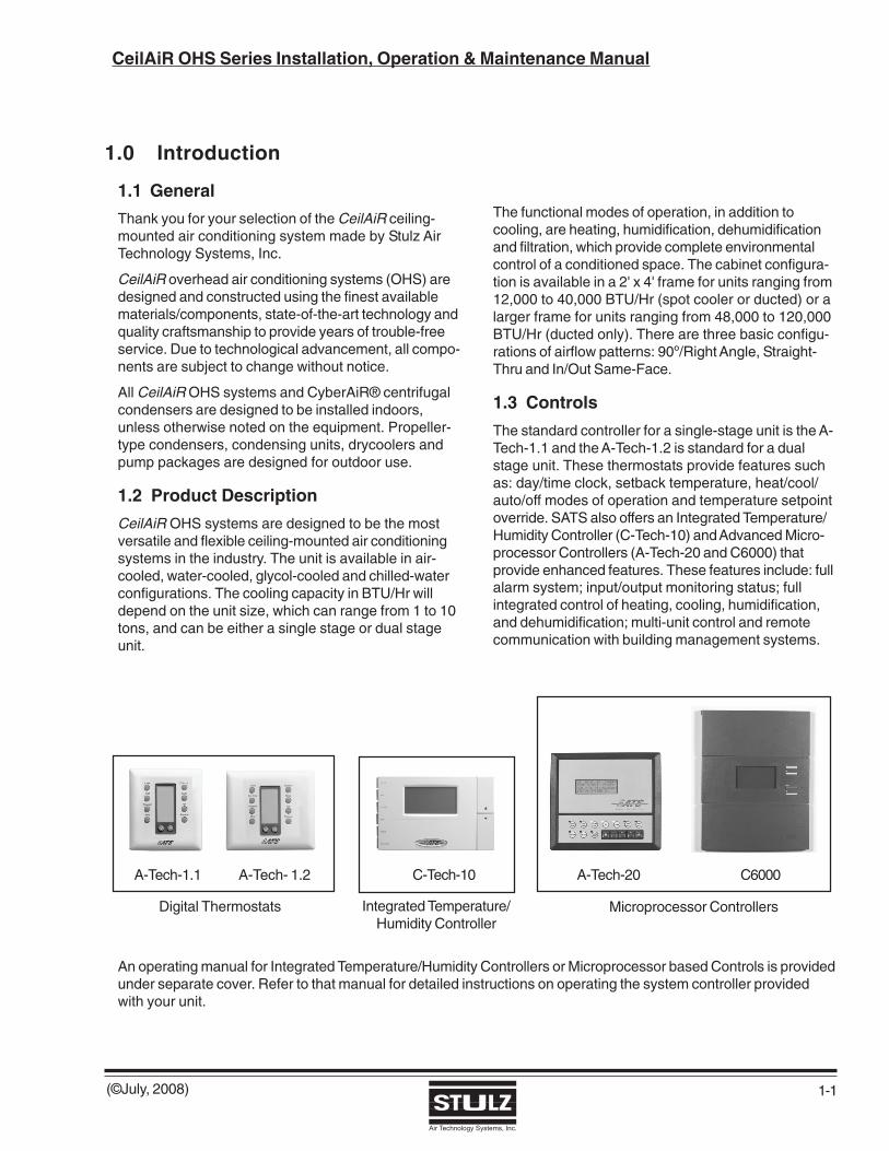
1.3 Controls
The standard controller for a single-stage unit is the A-Tech-1.1 and the A-Tech-1.2 is standard for a dualstage unit. These thermostats provide features suchas: day/time clock, setback temperature, heat/cool/auto/off modes of operation and temperature setpointoverride. SATS also offers an Integrated Temperature/Humidity Controller (C-Tech-10) and Advanced Micro-processor Controllers (A-Tech-20 and C6000) thatprovide enhanced features. These features include: fullalarm system; input/output monitoring status; fullintegrated control of heating, cooling, humidification,and dehumidification; multi-unit control and remotecommunication with building management systems.
1-1
An operating manual for Integrated Temperature/Humidity Controllers or Microprocessor based Controls is providedunder separate cover. Refer to that manual for detailed instructions on operating the system controller providedwith your unit.
A-Tech- 1.2A-Tech-1.1 A-Tech-20C-Tech-10 C6000
Digital Thermostats Microprocessor ControllersIntegrated Temperature/Humidity Controller

(©July, 2008)
CeilAiR OHS Series Installation, Operation & Maintenance Manual
Air Technology Systems, Inc.
1-2
1.4 Product Warranty
SATS offers a two year standard limited warranty as stated on the following pages. Additionally an extendedwarranty may be purchased on the unit's compressor. Consult the factory to verify if the extended compressorwarranty was purchased for your system. The compressor warranty as stated on the next page will be sent withyour unit and should be retained for future reference.
2-Year Standard Limited Warranty:Stulz Air Technology Systems, Inc., warrants to the original buyer of its products that the goodsare free from defects in material and workmanship. Stulz Air Technology Systems, Inc.’sobligation under this warranty is to repair or replace, at its option, free of charge to the customer,any part or parts which are determined by Stulz Air Technology Systems Inc. to be defectivefor a period of 24 months from date of shipment when a completed start-up form has beensubmitted to Stulz Air Technology Systems, Inc. within 90 days from shipment. In the eventthat a completed start-up form is not received by Stulz Air Technology Systems, Inc. within 90days from shipment, the company’s obligation will be for a period of 12 months from date ofshipment. Parts repaired or replaced under this warranty are shipped FOB Factory, andwarranted for the balance of the original warranty period or for 90 days from the date ofinstallation, whichever is greater.
Stulz Air Technology Systems, Inc.’s warranty does not cover failures caused by improperinstallation, abuse, misuse, misapplication, improper or lack of maintenance, negligence,accident, normal deterioration (including wear and tear), or the use of improper parts or improperrepair.
Purchaser’s remedies are limited to replacement or repair of non-conforming materials inaccordance with the written warranty. This warranty does not include costs for transportation,costs for removal or reinstallation of equipment or labor for repairs or replacement made in thefield.
If any sample was shown to the buyer, such sample was used merely to illustrate the generaltype and quality of the product, and not to represent that the equipment would necessarilyconform to the sample.
This is the only warranty given by the seller, and such warranty is only given to buyers forcommercial or industrial purposes. This warranty is not enforceable until the invoice(s) is paidin full.
THE FOREGOING SHALL CONSTITUTE SATS’S ENTIRE LIABILITY AND YOUR EXCLUSIVEREMEDY. IN NO EVENT SHALL SATS BE LIABLE FOR ANY DIRECT, INDIRECT, SPECIAL,INCIDENTAL, CONSEQUENTIAL, OR EXEMPLARY DAMAGES, INCLUDING LOST PROFITS(EVEN IF ADVISED OF THE POSSIBILITY THEREOF) ARISING IN ANY WAY OUT OF THEINSTALLATION, USE OR MAINTENANCE OF THE EQUIPMENT. THIS WARRANTY IS INLIEU OF ALL OTHER WARRANTIES, EXPRESS OR IMPLIED, INCLUDING WARRANTIES OFMERCHANTABILITY OR FITNESS FOR A PARTICULAR PURPOSE.
������������������������������
������������������������������
��
��
��
��
��
��
��
��
��
��
��
��
��
��
��
��
�
��
��
��
��
��
��
��
��
��
��
��
��
��
��
��
��
��

(©July, 2008)
CeilAiR OHS Series Installation, Operation & Maintenance Manual
Air Technology Systems, Inc.
1-3
Optional Limited Extended Warranty (5 Years Total)
Stulz Air Technology Systems, Inc., warrants to the original buyer of its product thatthe compressor(s) listed below are warranted for parts replacement (not includinglabor) for extended period of 4 years from the date of expiration of the standardequipment warranty.
Stulz Air Technology Systems' warranty does not cover failures caused by improper
installation, abuse, misuse, misapplication, improper or lack of maintenance, negligence,
accident, normal deterioration including normal wear and tear, or the use of improper
parts or improper repair as determined by SATS.
This warranty does not include costs of transportation, cost for removal or reinstallation
of equipment or labor for repairs or replacement made in the field.
The obligation and liability of Stulz Air Technology Systems under this warranty does not
include losses, direct or indirect, for incidental or consequential damages.
Compressor Serial No.: __________________________________
Unit Model No.: __________________________________
Unit Serial No.: __________________________________
Stulz Air Technology Systems Job No.: __________________________________
End User: __________________________________
Date: __________________________________
����������������������������������
����������������������������������
��
��
��
��
��
��
��
��
��
��
��
��
��
��
��
��
��
��
��
�
��
��
��
��
��
��
��
��
��
��
��
��
��
��
��
��
��

(©July, 2008)
CeilAiR OHS Series Installation, Operation & Maintenance Manual
Air Technology Systems, Inc.
1.5 Safety
1.5.1 General
Stulz Air Technology Systems, Inc. uses notes alongwith caution and warning symbols throughout thismanual to draw your attention to important opera-tional and safety information.
A bold text NOTE marks a short message in theinformation to alert you to an important detail.
A bold text CAUTION safety alert appears withinformation that is important for protecting yourequipment and performance. Be especially careful toread and follow all cautions that apply to your applica-tion.
A bold text WARNING safety alert appears withinformation that is important for protecting you fromharm and the equipment from damage. Pay veryclose attention to all warnings that apply to yourapplication.
A safety alert symbol precedes a generalWARNING or CAUTION safety statement.
A safety alert symbol precedes an electricalshock hazard WARNING or CAUTION safetystatement.
1.5.2 Safety Summary
The following statements are general guidelinesfollowed by warnings and cautions applicablethroughout the manual.
Prior to performing any installation, operation, mainte-nance or troubleshooting procedure read and under-stand all instructions, recommendations and guide-lines contained within this manual.
WARNING This equipment should be serviced and repairedby a journeyman, refrigeration mechanic or anair conditioning technician.
WARNING
To prevent personal injury, stay clear of rotatingcomponents as automatic controls may startthem unexpectedly. Turn off power to the unitunless you are performing tests that requirepower. With power and controls energized, theunit could begin operating at any time.
WARNING
Never operate the unit with any cover, guard,screen panel, etc. removed unless the instruc-tions specifically state otherwise, then do so withextreme caution to avoid personal injury.
CAUTION Never lift any component in excess of 35 poundswithout help. If a lifting device is used to move aunit ensure it is capable of supporting the unit.
CAUTION Do not allow the unit to swing while suspendedfrom a lifting device. Failure to observe this warn-ing may result in injury to personnel and dam-age to the equipment.
WARNING
When working on electrical equipment, removeall jewelry, watches, rings, etc.
WARNING
Always disconnect the main power supply be-fore beginning work on the equipment. A lock-out tag-out procedure should be followed to en-sure that power is not inadvertently reconnected.
Never work on electrical equipment unless an-other person who is familiar with the operationand hazards of the equipment and competent inadministering first aid is nearby.
All personnel working on or near equipment shouldbe familiar with hazards associated with electri-cal maintenance. Safety placards/stickers havebeen placed on the unit to call attention to allpersonal and equipment damage hazard areas.
1-4

(©July, 2008)
CeilAiR OHS Series Installation, Operation & Maintenance Manual
Air Technology Systems, Inc.
WARNING
This unit employs high voltage equipment withrotating components. Exercise extreme care toavoid accidents and ensure proper operation.
WARNING
Hazardous voltage will still be present inside theelectric box, even with the unit turned off at thesystem controller. To isolate the unit for mainte-nance, turn off power at the main power discon-nect switch. Always disconnect main power priorto performing any service or repairs.
WARNING Refrigerant (R22 or R407C) is used with thisequipment. Death or serious injury may result ifpersonnel fail to observe proper safety precau-tions. Great care must be exercised to preventcontact of liquid refrigerant or refrigerant gas, dis-charged under pressure, with any part of thebody. The extremely low temperature resultingfrom the rapid expansion of liquid refrigerant orpressurized gas can cause sudden and irrevers-ible tissue damage.
As a minimum, all personnel should wear ther-mal protective gloves and face-shield/goggleswhen working with refrigerant. Application of ex-cessive heat to any component will cause ex-treme pressure and may result in a rupture.
Exposure of R22 to an open flame or a very hotsurface will cause a chemical reaction that willform carbonyl chloride (hydrochloric/hydrofluo-ric acid); a highly poisonous and corrosive gascommonly referred to as PHOSGENE. In itsnatural state, refrigerant is a colorless, odorlessvapor with no toxic characteristics. It is heavierthan air and will disperse rapidly in a well-venti-lated area. In an unventilated area, it presents adanger as a suffocant.
Always refer to the manufacturer’s MSDS pro-vided with the unit.
1-5
WARNING When performing soldering or desoldering op-erations, make certain the refrigeration systemis fully recovered and purged and dry nitrogen isflowing through the system at the rate of notless than 1-2 CFM (0.028-0.57 M ³/minute).
CAUTION Certain maintenance or cleaning proceduresmay call for the use and handling of chemicals,solvents, or cleansers. Always refer to themanufacturer’s Material Safety Data Sheet(MSDS) prior to using these materials. Cleanparts in a well-ventilated area. Avoid inhalationof solvent fumes and prolonged exposure of skinto cleaning solvents. Wash exposed skin thor-oughly after contact with solvents.
CAUTION When the air conditioner is in the cooling mode,the return air-intake and discharge (supply)must be free of obstructions. Ensure panels aresecure and latched into position.
CAUTION Do not use cleaning solvents near open flame orexcessive heat. Wear eye protection when blow-ing solvent from parts. The pressure-wash shouldnot exceed 30 psig. Solvent solutions should bedisposed of in accordance with local and stateregulatory statutes.
CAUTION The unit must be kept in its normal installed po-sition. If the unit is not kept level and horizontal,damage to the compressor(s) will result.

(©July, 2008)
CeilAiR OHS Series Installation, Operation & Maintenance Manual
Air Technology Systems, Inc.
1.6 General Design
The CeilAiR unit is housed in an aluminum frame type cabinet and is rated for indoor use. Access panels are locatedon the front and rear of the cabinet for easy access to all components. Additional access may be obtained to somecomponents through the bottom of the unit on spot cooler configurations. The unit has an electrical box inside thecabinet with a removable panel for accessing the electrical components. Operator controls may be convenientlylocated on a wall within the space to be conditioned.
NOTECustomer specified non standard features or design variations may not be described in this manual. Refer tothe installation and electrical drawings supplied with your unit for details on additional feature(s). In somecases, an addendum to this manual may also be included to further describe the feature(s).
1-6
1.6.1 Electric Box Access
The electrical components are protected in an enclo-sure located in the cabinet behind an access panel.Before opening the access panel, turn off power at themain power service disconnect switch. This removespower from the system controller and shuts the unitoff.
1.6..2 Coil(s)
The cooling and optional hot water reheating coils arealuminum finned/copper tube construction. The coilsare leak tested and cleaned before installation by thefactory.
1.6.3 Blower
The unit is equipped with a centrifugal blower withforward curved blades. The blower is contained in adouble-width, double-inlet housing. The blower isdynamically and statically balanced to minimizevibration.
The blower motor is ODP industrial duty and utilizespermanently lubricated ball bearings. Smaller CeilAiRunits (models OHS-012/040) use direct drive blowers(except “H”-series models configured for horizontaldischarge).
Larger units (models OHS-048/120) and horizontaldischarge units (models OHS-012/040-H), use a beltdriven blower. The belt driven blower motor is mountedon an adjustable base for belt tensioning and isfurnished with an adjustable pitch sheave to adjustblower speed (see Figure 13).
1.6.4 Temperature Sensor
As a standard for systems utilizing a wall mounted A-Tech 1.1 or A-Tech 1.2 thermostat, the temperaturesensor is built into the thermostat for room air control.The sensor monitors the room air conditions andprovides input signal(s) to the system controller. Thesystem controller manages the operation of the A/Cunit consistent with the setpoints entered.
As an option, the temperature sensor may be shippedloose for field installation in the room to be condi-tioned. Refer to the electrical drawing supplied withyour unit for details specific to your system.

(©July, 2008)
CeilAiR OHS Series Installation, Operation & Maintenance Manual
Air Technology Systems, Inc.
1.6.5 Optional Equipment
1.6.5.1 Humidistat/Dehumidistat
As an option for systems utilizing an A-Tech 1.1 or A-Tech 1.2 thermostat, a room mounted humidistat and/or dehumidistat may be shipped loose for field installa-tion. Each device has an adjustment dial on the frontwhere the operator selects the desired setpoint.
If an optional humidifier is selected, the humidistat isincluded to control it’s operation. The humidistatcontrols the humidifier’s operation independant of thecontrol thermostat however, the blower must be on forthe humidifier to operate.
If the heat/reheat option is selected, a dehumidistat isprovided. If room humidity rises above setpoint when thedemand for cooling is satisfied, the dehumidistat signalsthe compessor to turn on, removing humidity. At the sametime, the heater(s) are turned on to offset the cooling effectthus maintaining the temperature of the space to beconditioned. Refer to the electrical drawing supplied withyour unit for details specific to your system.
1.6.5.2 Temperature/Humidity Sensor
As a standard for systems utilizing C-Tech 10, A-Tech20 or C6000 controllers, a temperature/humidity (T/H)sensor is typically factory mounted in the return airstream for room air control. As an option, the T/Hsensor may be shipped loose for field installation.Refer to the electrical drawing supplied with your unitfor details specific to your system.
1.6.5.3 Heaters
The precision A/C unit may incorporate heaters forreheating the supply air as required to offset thesensible cooling of the system during the dehumidifi-cation cycle and for the automatic heating mode.Heaters are typically placed in the supply air streamafter the cooling coil to heat the supply air.
Nichrome wire electric resistance heating elementsmay be factory installed in the supply airstream.Electric heating elements are protected with linefuses, thermal fuse links and over-temperature safetyswitches which automatically reset.
As an option, hot water reheat may be selected forsensible reheating during the dehumidification cycle. Ahot water heating coil may be factory installed in thesupply air stream. A valve is provided to control theflow of hot water through the coil to maintain thecorrect reheat temperature.
1-7
Hot Gas Reheat may be selected (for CeilAiR unitswith DX cooling only) for automtic sensible reheatingduring the dehumidification cycle. Hot compressordischarge gas is diverted from the condenser to a hotgas heating coil mounted in the supply air stream.
1.6.5.4 Humidifier
CeilAiR systems may utilize an optional electrodesteam humidifier. The humidifier is factory installedinside the air conditioner and includes fill and drainvalves and associated piping. Operation of thehumidifier’s fill and drain cycles is based on waterconductivity and is maintained by the humidifiercontroller. An operating manual for the humidifier isprovided under separate cover. Refer to that manual fordetailed information on operation of the humidifier.
1.6.5.5 Condensate Pump
An optional factory installed condensate pump may beprovided. The pump automatically eliminates conden-sate and humidifier flush water (if applicable) from thedrain pan. Should an overflow occur, an internaloverflow safety switch is wired to the system controllerto automatically shut down the precision A/C system.
1.6.5.6 Smoke Detector
Optionally mounted in the return air stream, a photo-electric smoke detector is used to sense the presenceof smoke and signal the controller when a smokealarm condition exists and shuts down the air condi-tioner.
1.6.5.7 Firestat
Optionally mounted in the return air stream, a firedetector senses high retun air temperature and signalsthe controller when a fire alarm condition exists andshuts down the air conditioner.
1.6.5.8 Water Detector
As an option, SATS offers spot type or strip/cable typewater detectors. Upon sensing a water leak, the waterdetector control circuit will signal the A/C systemcontroller of the alarm condition and shut down the airconditioner’s water producing operation.

(©July, 2008)
CeilAiR OHS Series Installation, Operation & Maintenance Manual
Air Technology Systems, Inc.
2.0 Installation
2.1 Receiving the Equipment
Your CeilAiR OHS system has been tested andinspected prior to shipment. To ensure that yourequipment has been received in excellent condition,make a visual inspection of the equipment immedi-ately upon delivery. Carefully remove the shippingcontainer and all protective packaging. Remove theaccess panels and thoroughly inspect the unit interiorfor any signs of transit-incurred damage. If there isshipping damage, it must be noted on the freightcarrier’s delivery forms BEFORE signing for theequipment. Any freight claims MUST be done throughthe freight carrier. SATS ships all equipment FOB.SATS can assist in the claim filing process with thefreight carrier. Should any damage be present, notifythe SATS Product Support Group prior to attemptingany repairs. Refer to section five of this manual forinstructions.
A unit Data Package has been sent with your unit. Itcontains this manual, system drawings, applicableMSDS’s, other component manuals and any otherapplicable instructions based on the configuration andoptions of your unit. The data package has beenaffixed to your unit in a clear plastic bag. Thesedocuments need to be kept with the unit for futureservice.
NOTE
Items that have been shipped loose such as con-trollers, humidistats, vibration isolators, buck/boost transformers, etc. are shipped inside theair conditioner unless specified otherwise by thecustomer. Grilles (if applicable) are placed ontop of the air conditioner inside the unit’s car-ton. Remove and store these items in a safeplace unless you are using them immediately.
2.2 Site Preparation
CeilAiR systems are designed with easy serviceaccess in mind. Component access panels arelocated on the front and rear sides of the equipment.Additional access to some components may beobtained through the bottom of the unit on spot coolerconfigurations. These units can be fully serviced in theceiling plenum. In order to have full service access, theair conditioner must be located so that adequatespace is provided in front of all access panels.
NOTE
Working clearance requirements need to beestablished prior to the mounting of the unit.Refer to local and national electrical codes.
To minimize the effects of the environment surroundingthe conditioned space, certain steps must be taken.This is especially true for critical/precision roompreparation (computer rooms/labs) requiring closetolerance control of temperature and humidity. Theconditioned space should be well insulated and includea vapor barrier. The installer should ensure that theproper insulation rating is used based on the design ofthe space, which was the basis for the system selected.The following chart is a recommended minimum R-value(thermal resistance) to ensure optimum equipmentoperation.
The vapor barrier is the single most important require-ment for maintaining environmental control in theconditioned space. The vapor barrier in the ceiling andwalls can be polyethylene film. Concrete walls andfloors should be painted with a rubber or plastic-basedpaint. Doors and windows should be properly sealedand a door sweep used to minimize leakage. Outsideor fresh air should be kept to a minimum (as it adds tothe cooling, heating, dehumidification and humidifyingloads), while maintaining the requirement of the IndoorAir Quality (IAQ) Standard. Lack of these steps cancause erratic operation, unstable room control andexcessive maintenance costs.
2.3 Rigging
CeilAiR systems are designed to be kept in thehorizontal position. Lift the unit from the bottom with asuitable lift device. A weight table is provided forreference on the installation drawing. The unit isshipped on a skid to facilitate moving prior to installa-tion. A suitable lifting device should be used whenmoving equipment. The unit should always be storedindoors in a dry location prior to installation.
STRUCTURE R-VALUECeiling R-38
Wall R-21Floor R-19Door R-5
2-1

(©July, 2008)
CeilAiR OHS Series Installation, Operation & Maintenance Manual
Air Technology Systems, Inc.
2-2
CAUTION
When moving the unit, it must be kept level and in thehorizontal position to prevent damage.
2.4 Mounting
CeilAiR OHS systems are designed for ceiling mount-ing in a suspended ceiling grid (spot cooler) or abovethe suspended ceiling for ducted systems.
NOTE
Do not install the A/C system directly aboveelectronic equipment which may hinderserviceability.
2.4.1 Indoor Equipment (See Figure 1)
CeilAiR OHS systems use a frame and panel configu-ration for unit rigidity and full service accessibility whilethe unit is mounted in place. The units are lifted intoplace from underneath and secured into place usingall-thread rods passing through rubber grommets or a4" x 4" neoprene cork pad in the mounting arms on thesides of the unit. All-thread, nuts and washers (fieldsupplied by others) must be secured so they do notloosen.
Before mounting the unit, ensure the mounting struc-ture is able to support the weight of the equipment.Refer to the weight table provided on the installationdrawing. Locate the mounting bolt holes or match drillthrough the support locations as needed and securethe unit with suitable hardware for the application. Anauxiliary drain pan is recommended and can bemounted directly under the cabinet.
2.4.2 Outdoor Equipment
Install remote condensers/condensing units in asecure location where the unit cannot be tamperedwith and the power service switch cannot be inadvert-ently turned off. Locate the remote condenser/con-densing unit where the fan is not likely to draw dirt anddebris into the coil fins. There should be at least 24inches of clearance around the condenser to ensureadequate airflow to the coil. Secure the condenser/condensing unit so the system will not move duringoperation. Refer to the installation drawing for the non-charged system weight. It is recommended that theremote condenser/condensing unit be mounted withvibration mounts to reduce the amount of vibrationtransmitted to the mounting surface.
2.4.3 Controls
NOTE
All thermostats/controls should not be locatednear a doorway, supply air register or area wherethey would be exposed to direct sunlight or otherfalse heat sources.
2.4.3.1 A-Tech-1.1/1.2 Programmable Thermostat
WARNING SATS supplied thermostats/controls do not con-tain mercury. Mercury is toxic and may be haz-ardous to health. Any replacement thermostatscontaining mercury must be disposed of prop-erly. Contact local authorities for disposal infor-mation.
(BY OTHERS)
Figure 1-TypicalInstallation
Note: Equipmentmust be levelto operateproperly.
(©July, 2008)
CeilAiR OHS Series Installation, Operation & Maintenance Manual
Air Technology Systems, Inc.
2-3
NOTE
SATS supplied thermostats/controls do not con-tain mercury.
Mount the thermostat upright on an inside wall withinthe conditioned room that best represents the averageroom temperature. In most cases, the thermostatshould be located near the common return air grille.Mount the thermostat at least 18 inches from anoutside wall and approximately 5 ft. above the floor.Follow the steps below to mount. Instructions forwiring the unit and setting the dip switches areprovided in Section 2.7, Utility Connections.
1. Unlatch the thermostat from the base. Removethe cover plate and, using a flat head screwdriver,gently insert into the latch access slot (bottom ofbase) until the lock tab disengages.
2. Pry up the handle of the screwdriver to separatethe thermostat panel from the base. Grip thebottom corners of the thermostat panel to removefrom base.
3. Place the base temporarily over the wire holeopening in the wall. Level the base and marklocation through the two provided mounting slots.
CAUTION Do not touch the temperature sensor on the bot-tom left corner of the thermostat. The sensorcan be damaged if handled improperly.
4. If using the supplied anchors, drill two 3/16 inchholes, tap in wall anchors. If only the suppliedscrews are being used, drill two 3/32 inch holes.
5. Fasten the base to the wall using the suppliedscrews.
6. Reinstall thermostat to base.
2.4.3.2 Humidistat/Dehumidistat (Optional Sup-plied with A-Tech-1.1/1.2 Thermostat)
Mounting of the humidistat and dehumidistat isperformed in the same manner. Mount the humidistatand/or dehumidistat (as described in Section 2.4.3.1)to a wall within the conditioned room that best repre-sents the average humidity of the space. In mostcases, the humidistat and dehumidistat should belocated near the common return air grille. Mount thehumidistat and dehumidistat at least 18” from anoutside wall and approximately 5 ft. above the floor.
Controls may be installed either on a flush switch boxor on a surface switch box. Follow the steps below tomount. Instructions for wiring of unit are are provided inSection 2.7, Utility Connections.
1. Pull dial knob off, loosen screw (located at bottomof unit) and remove cover.
2. Make wiring connections (see Section 2.7).
3. Mount with the two #6 screws provided.
4. For external setpoint, reinstall cover, tightenscrew, and replace dial knob.
5. For internal setpoint:a. Turn dial plate to desired setting and tighten
dial lock screw.b. Break off dial shaft at undercut.c. Remove insert from cover.d. Remove protective backing from adhesive on
the blank insert provided and press firmly inplace on cover.
e. Reinstall cover assembly and tighten screw. (Ifadditional security is required an Allen screwand wrench are provided.)
f. Remove protective cover from face of coverinsert.
2.4.3.3 Advanced Controllers(C-Tech 10, A-Tech-20 or C6000)
If you purchased this option, a separate manual issent in the unit data package affixed to your unit. Referto that manual and the electrical drawing(s) providedwhen mounting the controller display. The controllerdisplay may be field mounted to a wall within theconditioned space or it may be located outside theconditioned space if desired. When locating thesensor, consider the length of wire to be used. As anoption, a 30 foot, 75 foot or 150 foot long cable may beprovided by SATS.
2.4.4 Optional Equipment
NOTE
Do not mount any optional equipment on theA/C unit’s access panels.
2.4.4.1 Transformer
The buck/boost transformer provided is encapsulatedand can be installed indoors or outdoors. If installedoutdoors, the unit should be installed with the wiringcompartment down to prevent entrance of moisture.For indoor floor installation the unit may be installed

(©July, 2008)
CeilAiR OHS Series Installation, Operation & Maintenance Manual
Air Technology Systems, Inc.
2-4
horizontally for ease of making wire connections. Eachtransformer has keyhole mounting slots for mountingwith bolts to desired surface (wall, floor or otherstructure capable of supporting its weight).
2.4.4.2 Condensate Pump (Field Installed)
The condensate pump should be as near to the airconditioning system as possible. The inlet holes in thepump must be below the lowest part of drain from unit.The pump has two mounting supports so it can behung on an adjacent wall. Ensure that the pump islevel for proper operation.
2.4.4.3 Non-Fused Service Switch
The non-fused service switch is used to disconnectmain power and isolate the unit during maintenance andservice. The switch has a lockable handle to lock powerout during maintenance periods. The case has a topkeyhole slotting mount and two holes in each bottomcorner for mounting. The hardware for mounting is fieldsupplied and varies with size of switch and location.
The non-fused service switch can be mounted near theunit or in a central location. The non-fused serviceswitches are rated for indoor or outdoor use. Ensurethat the proper type for your application is used.
NOTE
Refer to local and national electrical codes formounting location.
2.4.5 Remote Sensors
The remote temperature sensor or the temperature/humidity (T/H) sensor must be located so that it willproperly sense the temperature and/or humidityconditions to be controlled. The sensor should not bemounted near a doorway or an area where it would beexposed to direct sunlight. When locating the sensor,consider the length of wire to be used. As an option, a75 foot or 150 foot long cable may be provided bySATS. Refer to the applicable section that follows tomount the sensor. For unit wiring details, refer toSection 2.7, Utility Connections and to the electricaldiagrams provided with the unit.
2.4.5.1 Remote Temperature Sensor
NOTEThe remote temperature sensor has a maximumrange of 300 feet.
1. Open the sensor case by depressing the button onthe bottom edge of the case until the latch releases.
2. Remove the cover by pulling it out and up at thebottom.
3. Remove the circuit board from the base by pullingback the latch that holds it at the center bottom.
4. Use the base as a template to mark the mountingholes location on the wall.
5. Using a ¼ inch drill, drill the holes and insert theprovided wall anchors.
6. Run the wires coming out of the wall through theopening in the base, then secure the base with thescrews provided.
7. Snap the circuit board back into the base. Ensurethat the latch holds the board properly and that thesensor element is positioned under the holes inthe cover but not touching the cover or base.
8. Make the wiring connections.
9. Replace the cover.
2.4.5.2 Remote Temperature/Humidity Sensor
1. Using a flat head screwdriver, remove the coverplate from the base of the sensor.
2. Place the base temporarily over the wire holeopening in the wall. Level the base and mark themounting hole locations through the two slots.
3. Drill the mounting holes and insert the providedwall anchors.
4. Run the wires coming out of the wall through theopening in the base, then secure the base with thescrews provided.
5. Make the wiring connections.
6. Replace the cover plate on the base.
CAUTION Take care not damage the exposed tempera-ture/humidity sensors on the PC board whilescrewing in the cover fastening screw. The sen-sors can be damaged if handled improperly.
2.4.5.3 Remote Water Detector
The remote water detector is normally placed in anauxiliary drain pan located under theunit. It may be attached using doublesided tape or with the mounting holesprovided in the flanges (one on eachside). Once it’s in place, loosen thescrews provided on the mounting legsto adjust the height of the sensing probes.

(©July, 2008)
CeilAiR OHS Series Installation, Operation & Maintenance Manual
Air Technology Systems, Inc.
2-5
CAUTION The probes must not touch the mounting surface.Failure to adhere to this may result in improperoperation of equipment.
2.4.5.4 Cable Type Water Detector
Lay the cable water detector across the surface wherewater could collect.When water ispresent, current willflow between the twowires.
2.5 Air Distribution Connection
2.5.1 Spot Cooler (See Figure 2)
For units that are not ducted, the air conditioner shouldbe mounted above the ceiling grid, leaving sufficientspace for the air grilles to rest on the ceiling T-bar.
NOTE
Placement of the grilles is important. The hingedfilter grille goes on the return air side of the unit.The 3-way directional grille goes on the condi-tioned air discharge side of the air conditioner.Gasketing is factory supplied for an air seal be-tween the bottom flange of the air conditionerand the grille. After mounting the air conditioner,lower the air conditioner until the gasket meetsthe grille.
Figure 2- Spot Cooler Grille
(©July, 2008)
CeilAiR OHS Series Installation, Operation & Maintenance Manual
Air Technology Systems, Inc.
2-6
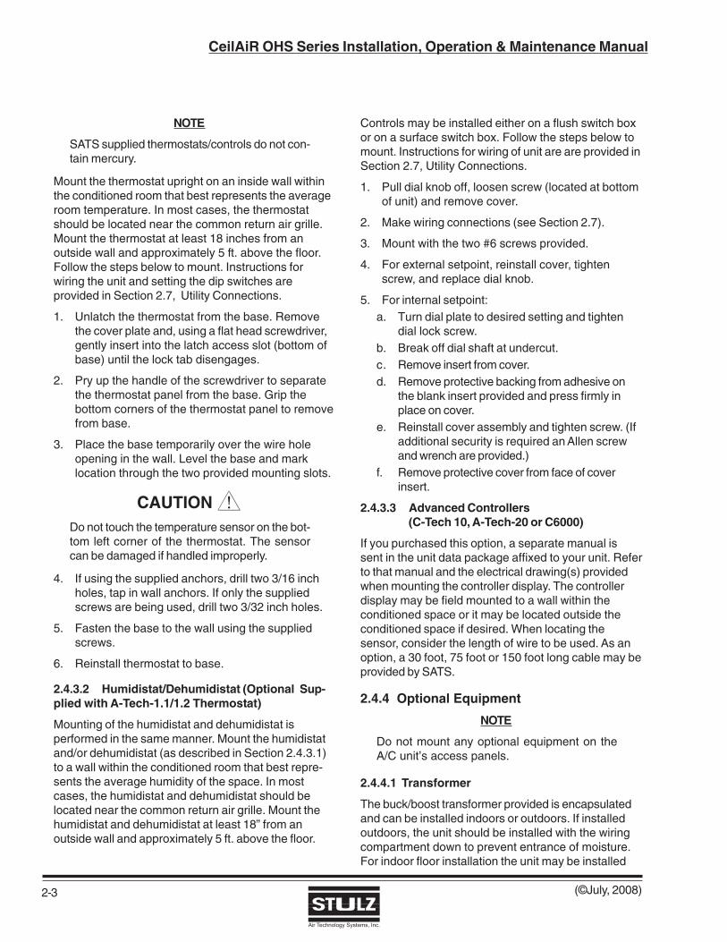
2.5.2 Ducted Systems (See Figure 3)
There are three basic configurations of airflow patterns: 90º/Right Angle, Straight-Thru and In/Out Same-Face.When determining ducting requirements, always consult your local and state codes. The duct system should bedesigned to allow the air to move with as little resistance as possible. Several factors determine ducting materialand size. These factors are predetermined, refer to your ducting system schematic.
The connection of ducting to the unit is typically accomplished with a one-inch duct flange. Supply air outlet andreturn air inlet ducts will require a field provided duct flange (refer to the installation drawing provided with the unit).The connection of ductwork to the unit may be made with either pop rivets or self-tapping screws.
2.6 Piping Connections
2.6.1 Refrigerant
2.6.1.1 Self-Contained SystemsNo refrigeration connections are required for self-contained air, water or glycol-cooled systems (ModelsOHS-012/040-AS, OHS-012/120-C and OHS-012/120-W/G-( )).
2.6.1.2 Split SystemsSplit air-cooled systems will require field refrigerationpiping. All split systems are shipped with a drynitrogen charge of 50 psig.
2.6.1.2.1 Remote Air Cooled Condensers(AR Models)
Systems utilizing air cooled condensers must not havea refrigerant line pressure drop over 14 psig across thecondenser and the interconnecting piping to thecondenser sections.
If the condenser is installed above the evaporator, thedischarge line should include a P-trap at the evapora-tor.
Figure 3- Ducted System Typical Air Patterns
NOTE
Ensure proper condenser selection to maintainreasonable subcooling temperatures.
If the condenser is installed below the evaporator, aninverted trap the height of the evaporator coil is requiredon the liquid line to help prevent oil and liquid fromflooding back to the compressor during off cycles.
Refer to the Recommended Discharge Line andRecommended Liquid Line sizing tables on page 2-7.
All refrigeration piping should be installed with hightemperature brazed joints. Use standard refrigerationpractices for piping supports, leak testing, dehydrationand charging of the refrigeration circuits. The refrigera-tion piping should be isolated from the building by theuse of vibration isolating supports. To prevent tubedamage when sealing openings in walls and to reducevibration transmission, use a soft flexible material topack around the tubes.

(©July, 2008)
CeilAiR OHS Series Installation, Operation & Maintenance Manual
Air Technology Systems, Inc.
2-7
Clear all pipe connections of debris and prep connec-tions for soldering. Use only “L” or “K” grade refrigerantcopper piping. Be careful not to allow solder/pipingdebris to get inside refrigerant lines. Silver soldercontaining a minimum of 15% silver is recommended.Dry nitrogen should be flowing through the tubing whilesoldering at a rate of not less than 1-2 CFM (0.028-0.57 M 3/minute).
Refrigerant lines for split systems must be sizedaccording to the piping distance between the evapora-tor and the condenser/condensing unit. Each valve,fitting and bend in the refrigerant line must be consid-ered in this calculation. Refer to the chart provided forstandard equivalent lengths, in feet, of straight pipe.
Oil traps must be included every 20 feet in the verticalrisers and the refrigerant lines must be sloped ¼ inchfor every 10 feet in the horizontal lines to ensure properoil return to the compressor. An inverted trap isrequired on the discharge line of the remote condenserto help prevent oil and liquid from flooding back to thecompressor.
NOTE
In the following 3 tables, the line sizes representthe correct size for individual refrigeration circuits.Dual circuit units, (Models 048D to 120D), havetwo separate pairs of refrigeration lines. One percompressor.
RECOMMENDED DISCHARGE LINE SIZES
Model No. / *Equivalent Length Ft.
Total Unit Capacity 50’or less 100’or less 150’or less
012 / 12,000 1/2 1/2 5/8
018 / 18,000 5/8 5/8 5/8
024 / 24,000 5/8 7/8 7/8
032 / 32,000 5/8 7/8 7/8
040 / 40,000 7/8 7/8 7/8
048 / 48,000 7/8 7/8 7/8
048D / 48,000 5/8 7/8 7/8
060 / 60,000 7/8 1-1/8 1-1/8
072D / 72,000 7/8 7/8 7/8
084D / 84,000 7/8 7/8 7/8
120D / 120,000 7/8 1-1/8 1-1/8
*Equivalent Ft. accounts for the linear pipe length as well asequivalent length of Valves, Elbows & Tee’s as shown in theprevious chart.
EQUIVALENT LENGTH (FT.) OF STRAIGHT PIPE
OD (In.) Globe Angle 90° 45° Tee Tee
Line Size Valve Valve Elbow Elbow Line Branch
1/2 9.0 5.0 0.9 0.4 0.6 2.0
5/8 12 6.0 1.0 0.5 0.8 2.5
7/8 15 8.0 1.5 0.7 1.0 3.5
1 1/8 22 12 1.8 0.9 1.5 4.5
1 3/8 28 15 2.4 1.2 1.8 6.0
CAUTION Do not exceed the maximum Liquid Line lengthsfor the system configurations listed below: RCU with Hot Gas Bypass ......... 50 Ft Remote Condensing Unit ........... 100 Ft Remote Air Cooled Condenser ... 150 Ft
RECOMMENDED LIQUID LINE SIZESCondenser to A/C Unit /
Model No. / Receiver to Evap. (*Equivalent Ft.) Total Unit Capacity 50’or less 100’or less 150’or less
012 / 12,000 3/8 3/8 3/8
018 / 18,000 3/8 3/8 1/2
024 / 24,000 3/8 1/2 1/2
032 / 32,000 1/2 1/2 1/2
040 / 40,000 1/2 5/8 5/8
048 / 48,000 1/2 5/8 5/8
048D / 48,000 3/8 1/2 1/2
060 / 60,000 1/2 5/8 5/8
072D / 72,000 1/2 1/2 1/2
084D / 84,000 1/2 5/8 5/8
120D / 120,000 1/2 5/8 5/8

(©July, 2008)
CeilAiR OHS Series Installation, Operation & Maintenance Manual
Air Technology Systems, Inc.
2-8
Vertical runs are based on a total rise of 30 equivalentfeet. For longer rises, individual calculations should bemade. Sizes assume the use of single risers; doublerises may be necessary.
NOTE
Consult the Copeland applications data guidefor more detailed information regarding refriger-ant line traps and line sizing.
2.6.1.2.2 Remote Air Cooled Condensing Units(AHU Models)
When installing remote condensing units above theevaporator, the suction line should be p-trapped at theevaporator.
NOTE
Do not exceed 15 feet of vertical distance wheninstalling the condensing unit below the evapo-rator.
When installing remote condensing units below theevaporator, the suction line should be trapped with aninverted trap the height of the evaporator coil. Thisprevents migration of liquid refrigerant to the compres-sor during off cycles.
All suction lines must be insulated to prevent conden-sation from forming on the pipes. Refer to providedpipe size charts for recommended pipe sizing.
2.6.2 Chilled Water, Water/Glycol and HotWater Reheat Piping
The piping connections for water/glycol, chilled waterand systems with hot water reheat are sweat connec-tions. Pipe sizes may not necessarily be the same asthe unit connection. Piping should be sized to matchthe system pressure drop and pump capacity (ifapplicable) and may require reducing fittings to matchthe connection size on the air conditioner. The recom-mended ethylene glycol solution ratio is 40% glycol to60% water. (SATS recommends Dowtherm SR1manufactured by Dow Chemical Co.) Glycol-cooledsystems with a low entering fluid temperature and allchilled water systems should have insulated piping.
WARNING Glycol is hazardous and the manufacturer’sMSDS should be consulted.
CAUTION When installing and filling the water/glycol,chilled water and optional hot water reheatloop, all air must be bled from the pipingsystem.
CAUTION The piping system must be flushed prior to op-erating the system. Failure to do so will resultin equipment problems.
A strainer should be included in the water/glycol,chilled water and optional hot water reheat line. Oncethe system is operational, the fluid runs through thestrainer where any foreign objects are removed. Thestrainer screen should be cleaned periodically.
H = Horizontal Run V = Vertical Run
RECOMMENDED SUCTION LINE SIZES
Model No. / *Equivalent Length Ft.
Total Unit Capacity 50’or less 100’or lessH V H V
012 / 12,000 5/8 5/8 5/8 5/8
018 / 18,000 7/8 7/8 7/8 7/8
024 / 24,000 7/8 7/8 7/8 7/8
032 / 32,000 7/8 7/8 1-1/8 7/8
040 / 40,000 7/8 7/8 1-1/8 1-1/8
048 / 48,000 1-1/8 1-1/8 1-1/8 1-1/8
048D / 48,000 7/8 7/8 7/8 7/8
060 / 60,000 1-1/8 1-1/8 1-1/8 1-1/8
072D / 72,000 7/8 7/8 1-1/8 7/8
084D / 84,000 1-1/8 1-1/8 1-1/8 1-1/8
120D / 120,000 1-1/8 1-1/8 1-1/8 1-1/8

(©July, 2008)
CeilAiR OHS Series Installation, Operation & Maintenance Manual
Air Technology Systems, Inc.
2-9
2.6.3 Condensate Drain Line
2.6.3.1 Gravity Drain
A 7/8 inch OD copper (sweat type) line is provided todrain the condensate drain pan. This line also drainsthe humidifier, if applicable. The drain line must belocated so it will not be exposed to freezing tempera-tures. The drain line should be the full size of theconnection. See the installation drawing provided withyour unit for the size and location of the condensatedrain line.
NOTEDuring normal operation the optional humidifierdrains (hot) water into the condensate drainline. As an option, a separate drain line may beprovided for the humidifier.
2.6.3.2 Condensate Pump (See Figure 4)
A condensate pump is used for automatic removal ofcondensate from the air conditioner and flush waterfrom the humidifier (if applicable). A p-trap must beinstalled for proper condensate drainage. The height ofthe trap must be a minimum of 2 inches on moststandard systems to ensure proper water drainage ofthe drain pan. The condensate pump discharge lineshould be 1/2 inch OD maximum copper or vinyl tubingto prevent excessive back flow to unit.
NOTE
Pour some water into the condensate drain(s)prior to start-up. This fills the trap and preventsair from being drawn up the drain lines.
2.6.4 Humidifier (Optional)
CeilAiR systems utilize an electrode steam humidifier.The humidifier empties into the condensate drain lineduring the flush/drain cycle. A water supply line mustbe connected to the copper tubing connection suppliedby the factory. Refer to the installation drawing pro-vided with your unit for the size and location of theconnection. The humidifier requires normal tap wateras the water supply. If the supply water is high inparticulate, an external filter may be needed.
CAUTION Do not use demineralized water.
Refer to the humidifier operator’s manual, supplied withthe equipment, for complete manufacturer’s informa-tion on the humidifier and the supply water recommen-dations.
Figure 4- Condensate Pump

(©July, 2008)
CeilAiR OHS Series Installation, Operation & Maintenance Manual
Air Technology Systems, Inc.
2-10
2.7 Utility Connections
2.7.1 Main Power
The CeilAiR product offering is available in single orthree phase variations and a wide range of voltages. Itis imperative that the unit nameplate be examined todetermine the operating voltage, frequency and phaseof the system (see Figure 5). The nameplate alsoprovides the full load amps (FLA), the current the unitwill draw under full design load, the minimum circuitampacity (MCA) for wire sizing, and the maximumfuse size (MAX FUSE) for circuit protection. The unit’snameplate is located on the outside of the cabinetwithin close proximity of the electrical box.
NOTE
If the nameplate states MAX FUSE/CKT BKR,it is required to use fuses or a HACR type cir-cuit breaker to protect the system. Other pro-tection devices are not allowed based upon theproduct listing.
The unit is provided with terminals for all required field-wiring. It is important to identify the options that werepurchased with the unit in order to confirm which fieldconnections are required. Refer to the electricaldrawing(s) supplied with the unit for the power andcontrol field-wiring.
WARNING Verify power is turned off before making connec-tions to the equipment.
NOTE
All wiring must conform to local and national elec-trical code requirements. Use of copper conduc-tors only is required. Wiring terminations maybecome loose during transit of the equipment;therefore, it is required to verify that all wiringterminations are secure.
It is important to verify that the main power supplycoincides with the voltage, phase and frequencyinformation specified on the system nameplate. Thesupply voltage measured at the unit must be within±10% of the voltage specified on the system name-plate.
A manual fused disconnect switch must be installedper local and national electrical codes for service ofequipment. Do not mount a shipped loose non-fusedservice switch or customer supplied disconnect switch
Figure 5- Sample Nameplate

(©July, 2008)
CeilAiR OHS Series Installation, Operation & Maintenance Manual
Air Technology Systems, Inc.
2-11
to the surface of the unit. If the factory installed, non-fused service switch option was purchased, the mainpower and ground connection shall be located at thenon-fused service switch, otherwise, the main powerconnection shall be located as stated below.
Each unit is provided with pilot hole(s) in the mainpower and control panel for connection of the field-wiring. These pilot holes are located near the electricalbox and a label stating "MAIN POWER INPUT" is inclose proximity. Terminate the main power wires at theline side of the main power distribution block locatedwithin the electric box. A separate equipment groundlug is provided within the electrical box for terminationof the earth ground wire.
2.7.1.1 Single-Phase Units 208/230V
Units that are designed for a 208V-supply voltage musthave a tolerance that is within -5% and +10%. If themeasured supply voltage is 230V, the unit can operatewith a tolerance of ±5% if the following change isperformed. The control transformers within the systemmust have the primary wire connected to its respective240V tap instead of the 208V tap.
2.7.1.2 Single-Phase Units 277V
Single-phase units require that the hot leg of power beconnected to terminal L1 and the neutral wire toterminal L2 of the main power distribution block.
2.7.1.3 Single-Phase Units (208/230V) with277/230V Buck/Boost TransformerApplications (See Figure 6)
Certain applications may require the purchase of a unitdesigned for a 208V, 1PH, 60Hz power supply andsupplied with a 277V/230V buck/boost transformer.This configuration allows the equipment to operatefrom a customer supplied 277V, 1PH, 60Hz powersupply. The purpose of the buck/boost transformer isto convert the incoming 277V, 1PH, 60Hz powersupply to the required 230V, 1PH, 60Hz power supplyfor unit operation. If the incoming power supply iswithin the range of 277V plus 5%, the control trans-formers within the system must have the primary wireconnected to its respective 240V tap instead of the208V tap.
NOTE
Prior to operation, an adequate unit-to-earth earthground must be connected to the unit
Figure 6- Transformer Schematic

(©July, 2008)
CeilAiR OHS Series Installation, Operation & Maintenance Manual
Air Technology Systems, Inc.
2-12
Upon examination of the buck/boost transformer, itmay be observed that the labeled primary voltage is120, 240 and/or 480 while the secondary voltage is 12,16, 24, 32 and/or 48 but not limited to these specificvoltages. This transformer is designed as an insulatingtransformer but if wired in a configuration recom-mended by the manufacturer it will change its electri-cal characteristics to those of an autotransformer(buck/boost transformer). The primary and secondarywindings are no longer insulated, which in this designproduces a lower voltage ratio between the primaryand secondary windings. This new wiring configurationalso results in an increased KVA capacity.
It should be noted that the 277V/230V buck/boosttransformer provided with the equipment has beenproperly sized and is approved for use as a buck/boosttransformer. The buck/boost transformer must beinstalled, wired and provided with overcurrent protec-tion in accordance with local and national electricalcode requirements. Please refer to the electricalschematic supplied with the unit for field connections.A disconnecting means is required for the system;sizing and location will depend on the location of thebuck/boost transformer with regards to the unit. Inaddition, wire sizing and overcurrent protection mustbe provided in accordance with the unit nameplateinformation between the buck/boost transformer andthe unit.
NOTE
This transformer is used on a wide variety ofapplications. Use the wiring instructions (thesame instructions are supplied with the trans-former) for the correct wiring method. Care shouldbe taken in wiring the transformer in accordancewith the supplied wiring schematic.
Connections are as follows:
1. Splice the hot leg (L1) of the 277V inlet to (X1) (2wires under this splice cap).
2. Splice the neutral leg (L2) of the 277V inlet to H4,H2 and the wire terminating at L2 of the unit mainpower distribution block (4 wires under this splicecap).
3. Splice wires (X2) and (X3) together (2 wires underthis splice cap).
4. Splice (H3), (H1), (X4) and the wire terminating atL1 of the unit main power distribution block (4wires under this splice cap).
5. The transformer chassis should be grounded.
After all wiring connections are complete, check thevoltage at the main power distribution block in theunit's electrical box to ensure the unit has the correctvoltage.
2.7.1.4Three-Phase Units
Three-phase units are designed to have the L1, L2 andL3 supply wires connected to corresponding L1, L2 andL3 line terminals of the main power distribution block.The unit will operate correctly if the supply wires areconnected in this manner. A ground lug is provided ineach unit near the distribution block.
CAUTION Improper wire connections will result in thereverse rotation of the fans/blower motors andcompressor (if applicable) and may eventuallyresult in damage to the scroll compressor. Tocorrect this problem, exchange any two of theincoming main power wires at the main powerdistribution block. Do NOT rewire the unit's individual components.
2.7.2 Controls
SATS offers a wide range of control systems to solveyour air conditioning control/alarm requirements. Referto your specific system to identify which controlpackage was purchased. This section will cover theelectrical wiring of the A-Tech-1.1 and A-Tech-1.2 thermo-stats with optional humidistat/dehumidistat controls. Ifyou purchased a C-Tech-10, A-Tech-20 or C6000controller, a supplemental manual was sent with yourunit. Refer to it and the wiring diagram(s) provided forutility connections. The air conditioning system isprovided with a pilot hole for a conduit connection for thecontrol wiring. It is located near the electrical box in closeproximity to the main power pilot hole. The sizing of theconduit must be per the local and national electrical coderequirements.
NOTEAll customer provided wiring must be in accor-dance with local and national electrical code re-quirements for Class 2 circuits.
(©July, 2008)
CeilAiR OHS Series Installation, Operation & Maintenance Manual
Air Technology Systems, Inc.
2-13
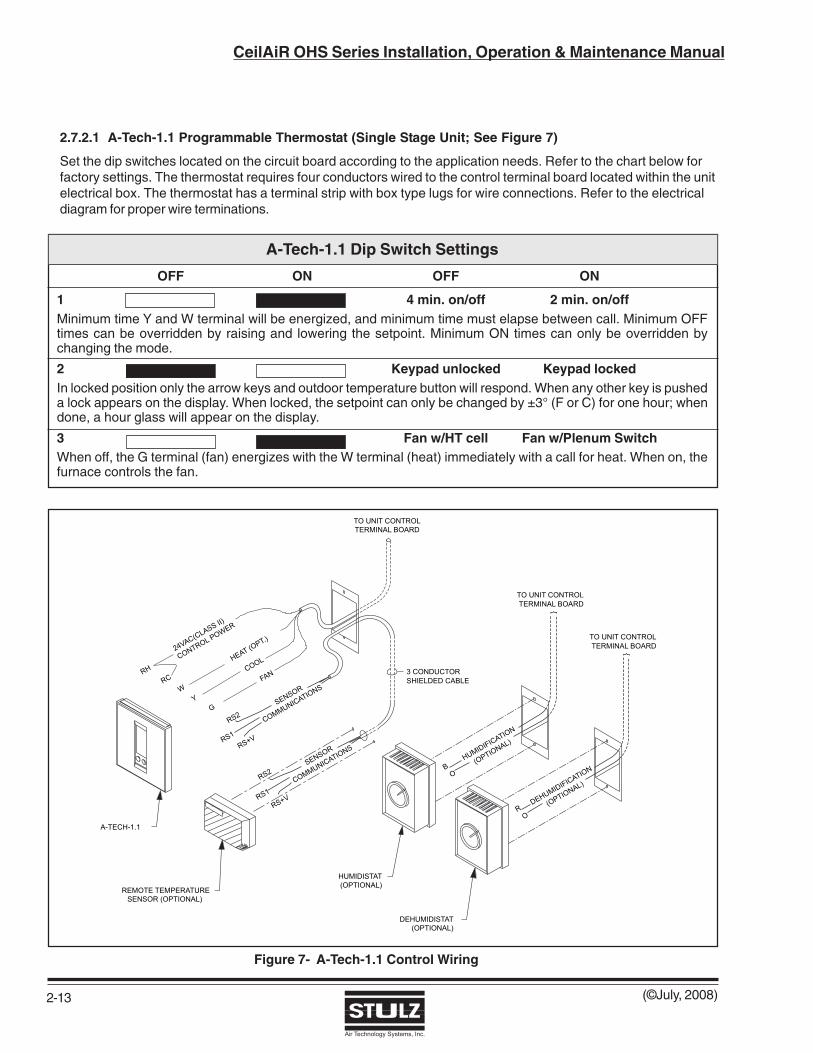
2.7.2.1 A-Tech-1.1 Programmable Thermostat (Single Stage Unit; See Figure 7)
Set the dip switches located on the circuit board according to the application needs. Refer to the chart below forfactory settings. The thermostat requires four conductors wired to the control terminal board located within the unitelectrical box. The thermostat has a terminal strip with box type lugs for wire connections. Refer to the electricaldiagram for proper wire terminations.
Figure 7- A-Tech-1.1 Control Wiring
A-Tech-1.1 Dip Switch Settings
OFF ON OFF ON
1 4 min. on/off 2 min. on/offMinimum time Y and W terminal will be energized, and minimum time must elapse between call. Minimum OFFtimes can be overridden by raising and lowering the setpoint. Minimum ON times can only be overridden bychanging the mode.
2 Keypad unlocked Keypad lockedIn locked position only the arrow keys and outdoor temperature button will respond. When any other key is pusheda lock appears on the display. When locked, the setpoint can only be changed by ±3° (F or C) for one hour; whendone, a hour glass will appear on the display.
3 Fan w/HT cell Fan w/Plenum SwitchWhen off, the G terminal (fan) energizes with the W terminal (heat) immediately with a call for heat. When on, thefurnace controls the fan.

(©July, 2008)
CeilAiR OHS Series Installation, Operation & Maintenance Manual
Air Technology Systems, Inc.
2-14
A-Tech-1.2 Dip Switch Settings
OFF ON OFF ON
1 4 Events/day 2 Events/dayFour events or two events for all seven days of the week. Four events are: Morning, Day, Evening, Night; twoevents are: Day and Night.
2 Smart Fan Disabled Smart Fan EnabledWhen enabled and continuous fan has been selected, the fan terminal (G) will de-energize during the Night eventand only cycle on with the equipment.
3 4 min. on/off 2 min. on/offMinimum time Y and W terminal will be energized, and minimum time must elapse between call. Minimum OFFtimes can be overridden by raising and lowering the setpoint. Minimum ON times can only be overridden bychanging the mode.
4 Keypad unlocked Keypad lockedIn locked position only the arrow keys and outdoor temperature button will respond. When any other key is pusheda lock appears on the display. When locked, the setpoint can only be changed by ±3° (F or C) for one hour; whendone, a hour glass will appear on the display.
5 Fan w/HT cell Fan w/Plenum SwitchWhen off, the G terminal (fan) energizes with the W terminal (heat) immediately with a call for heat. When on, thefurnace controls the fan.
6 Single Stage Multi-StageIn Single Stage position, terminals Y2 and W2 are locked out
7 No LCD w/LED 1 Filter LCD w/LED 1In Filter position, when terminal LED 1 is energized a "replace filter" picture appears on the LCD in addition to LED1 illuminating.
8 No LCD w/LED 2 Wrench LCD w/LED 2In wrench position, when terminal LED 2 is energized a picture of a wrench appears on the LCD in addition to LED2 illuminating.
2.7.2.3 Humidistat/Dehumidistat (Optional)
The humidistat/dehumidistat are mounted in the same manner but are wired differently. The humidistat/dehumidistat both require two conductors for connection to the air conditioning system. The controls provide pigtailleads for splice type wire connections with twist on connectors (wire caps). Refer to the supplied electrical sche-matic for proper wire terminations.
2.7.2.2 A-Tech-1.2 Programmable Thermostat(Dual Stage Unit; See Figure 8)
Set the dip switches located on the circuit board according to the application needs. Refer to the following chartprovided for factory settings. The thermostat requires seven conductors wired to the control terminal board locatedwithin the unit electrical box. The thermostat provides a terminal strip with box type lugs for wire connections.Refer to the supplied electrical schematic for proper wire terminations.

(©July, 2008)
CeilAiR OHS Series Installation, Operation & Maintenance Manual
Air Technology Systems, Inc.
2-15
2.7.3 Optional Equipment
NOTEAll customer provided wiring must be in accor-dance with local and national electrical code re-quirements for Class 2 circuits.
2.7.3.1 Condensate Pump
Systems supplied with a field installed condensatepump will require power and control wiring to beconnected to the unit. The control wires from theterminal board in the electric box should be runthrough the overflow switch in the condensate pumphousing. After proper installation of the condensatepump, the installer must connect two power conduc-tors from the condensate pump main power terminalsto the air conditioning unit. A ground wire must be
connected to the unit ground stud located within theunit electric box. Two control conductors must bewired to the control terminal board located within theunit electric box. The condensate pump providespigtail leads for splice type wire connections with twiston connectors (wire caps). Refer to the suppliedelectrical diagram for proper wire terminations.
2.7.3.2 Remote Temperature Sensor(See Figures 7 and 8)
The remote temperature sensor requires a threeconductor shielded cable with the shield being termi-nated at the thermostat. The shield is terminated atthe RS2 thermostat terminal. Both the thermostat andthe sensor provide a terminal strip with box type lugsfor wire connections. Refer to the electrical diagramsupplied for proper wire terminations.
Figure 8- A-Tech-1.2 Control Wiring

(©July, 2008)
CeilAiR OHS Series Installation, Operation & Maintenance Manual
Air Technology Systems, Inc.
2-16
2.7.3.3 Remote Water Detector
Spot Type:A remote spot type water detector requires threeconductors to be wired to the control terminal boardwithin the unit electrical box. The wire insulation mustbe rated at 600V. The water detector provides pig-tailleads for splice type wire connections with twist onconnectors (wire caps). Refer to the supplied electricaldiagram for proper wire terminations.
Strip/Cable Type:A remote strip/cable type water detector is providedwith a two conductor cable harness with a quickconnect fitting on the end. The harness mates to thefitting on the water detector and connects it to thecontrol board inside the electric box. Refer to thesupplied electrical diagram for proper wire termina-tions.
2.7.4 Air-Cooled Split Systems
The following system interconnecting field wiringsections detail the number of conductors required for atypical system. Additional control conductors may berequired depending on the options purchased with theequipment. Refer to the supplied electrical diagram todetermine the total number of interconnecting conduc-tors required for your system. It is important to notethat the control transformer(s) supplied with theequipment have been sized and selected based uponthe expected loads for each system.
CAUTION Do not connect any additional loads to the sys-tem control transformers. Connecting additionalloads to the factory supplied controltransformer(s) may result in overloading of thetransformer.
NOTE
All wiring must be provided in accordance withlocal and national electrical code requirementsfor Class 2 circuits.
2.7.4.1 Remote Condenser (See Figure 9)
Systems equipped with a remote condenser requirefield wiring between the evaporator system and theremote condenser. Refer to the supplied electricalschematic and the wiring diagram supplied with thecondenser (typically located in the condenser electricbox). The installer must provide main power wiring tothe main power distribution block located within the
remote condenser control box. A separate equipmentground lug is provided within the electrical box fortermination of the earth ground wire.
The installer must also wire two control conductorsfrom the terminal board within the evaporator unit tothe control terminal board within the remote condensercontrol box. Refer to the supplied electrical diagram forproper wire terminations.
2.7.4.2 Remote Condensing Unit(See Figure 10 and 11)
Systems equipped with a remote condensing unitrequire field wiring between the evaporator system andthe remote condenser unit. The number of conductorsrequired between the two systems varies based uponthe number of options provided. A single stage coolingsystem typically requires three conductors. Refer tothe supplied electrical diagram(s) to determine theexact amount of field wires and proper wire termina-tions required for your specific unit.
2.7.5 Water/Glycol Systems (See Figure 12)
The following system interconnecting field wiringsections detail the number of conductors required for atypical system. Additional control conductors may berequired depending on the options purchased with theequipment. Refer to the supplied electrical diagram todetermine the total number of interconnecting conduc-tors required for your system. It is important to notethat the control transformer(s) supplied with theequipment have been sized and selected based uponthe expected loads for each system.
CAUTION Do not connect any additional loads to the sys-tem control transformers. Connecting additionalloads to the factory supplied controltransformer(s) may result in overloading of thetransformer.
NOTE
All wiring must be provided in accordance withlocal and national electrical code requirementsfor Class 2 circuits.
Systems equipped with a glycol-cooled system/pumppackage require field wiring between the glycol unit andpump package. The installer must wire two controlconductors from the terminal board within the glycol unitto the pump package electrical box. Refer to the suppliedelectrical schematic for proper wire terminations.

(©July, 2008)
CeilAiR OHS Series Installation, Operation & Maintenance Manual
Air Technology Systems, Inc.
2-17
SEE NOTE 3
REMOTE TEMPERATURE SENSOR (OPTIONAL)
SEE NOTE 3
C6000
4 CONDUCTORNON-SHIELDED CABLE
SHIELDED CABLE2 CONDUCTOR
6 CONDUCTOR PHONE TYPENON-SHIELDED CABLE
A-TECH-20 REMOTE TEMPERATURE/HUMIDITY SENSOR (OPTIONAL)
mode
resume
clock
2 CONDUCTORSHIELDED CABLE
C-TECH-10
5 CONDUCTORSHIELDED CABLE
Figure 9- Interconnection Field Wiring Remote Condenser
Figure 10- Interconnection Field Wiring Remote Condensing Unit
SEE NOTE 3
3. OPTIONAL REMOTE MOUNTED DEVICES (WIRE DIRECTLY TO A/C UNIT TERMINAL BLOCK)
SEE NOTE 3
C6000
4 CONDUCTORNON-SHIELDED CABLE
SHIELDED CABLE2 CONDUCTOR
6 CONDUCTOR PHONE TYPENON-SHIELDED CABLE
A-TECH-20
REMOTE CONDENSING UNIT
REMOTE TEMPERATURE/HUMIDITY SENSOR (OPTIONAL)
mode
resume
hold
set
fan
clock
2 CONDUCTORSHIELDED CABLE
C-TECH-10
5 CONDUCTORSHIELDED CABLE

(©July, 2008)
CeilAiR OHS Series Installation, Operation & Maintenance Manual
Air Technology Systems, Inc.
2-18
3. OPTIONAL REMOTE MOUNTED DEVICES (WIRE DIRECTLY TO A/C UNIT TERMINAL BLOCK)
SEE NOTE 3
SEE NOTE 3
C6000
4 CONDUCTORNON-SHIELDED CABLE
SHIELDED CABLE2 CONDUCTOR
6 CONDUCTOR PHONE TYPENON-SHIELDED CABLE
A-TECH-20REMOTE TEMPERATURE/HUMIDITY SENSOR (OPTIONAL)
mode
resume
hold
set
fan
clock
2 CONDUCTORSHIELDED CABLE
C-TECH-10
5 CONDUCTORSHIELDED CABLE
Figure 12- Interconnection Field Wiring Glycol Systems
Figure 11- Interconnection Field Wiring Remote Condensing Unit with Dual Compressors
SEE NOTE 3
C6000
4 CONDUCTORNON-SHIELDED CABLE
SHIELDED CABLE2 CONDUCTOR
6 CONDUCTOR PHONE TYPENON-SHIELDED CABLE
A-TECH-20
3. OPTIONAL REMOTE MOUNTED DEVICES (WIRE DIRECTLY TO A/C UNIT TERMINAL BLOCK)
REMOTE CONDENSING UNIT
REMOTE TEMPERATURE/HUMIDITY SENSOR (OPTIONAL)
mode
resume
hold
set
fan
clock
2 CONDUCTORSHIELDED CABLE
C-TECH-10
5 CONDUCTORSHIELDED CABLE
SEE NOTE 3

(©July, 2008)
CeilAiR OHS Series Installation, Operation & Maintenance Manual
Air Technology Systems, Inc.
2-19
2.7.6 Remote Shut Down
NOTE
All wiring must be provided in accordance with localand national electrical code requirements for Class 2circuits.
Each unit is provided with a means to remotely shutdown the air conditioning unit. A normally closedswitch rated at 5 amperes at 24VAC is required for thispurpose. Two conductors from the normally closedswitch must be connected to the control terminalboard located within the unit electric box. Refer to thesupplied electrical schematic for proper wire termina-tions.
2.8 Refrigerant Charging Procedures
Refrigerant charging procedures vary depending on thetype of refrigerant used in the unit. Before charging,check the unit nameplate to confirm the refrigeranttype. If the unit operates with R22 refrigerant seesection 2.8.1. If R407C is used, see section 2.8.2.
NOTE
Refrigerant charging must be performed by a jour-neyman, refrigeration mechanic or an air condi-tioning technician.
2.8.1 R22 Refrigerant Charging Procedures
2.8.1.1 Self-Contained Systems
All self-contained water/glycol-cooled units (units thatrequire no refrigerant field piping) are factory chargedwith R22. No field charging is required.
2.8.1.2 Remote Air-Cooled Split Systems (AR/AHU)
Remote air-cooled units are factory equipped with adry nitrogen holding charge, which must be removedbefore piping and charging the unit.
PREPARING SYSTEM FOR CHARGING
1. Once all connections have been made, pressurizethe system to 150 psig with dry nitrogen. Leaksmay be detected by checking the standingpressure.
2. After ensuring there are no leaks, relieve pressureand evacuate the system. Pull a vacuum of 50microns or less using the suction and dischargeservice ports and the service port of the receiver (ifapplicable). Hold the vacuum for 2 hours. Ensure
no portion of system has been isolated from theevacuation process (liquid, suction or dischargelines).
CAUTION A proper vacuum must be drawn on the refriger-ant system prior to charging. If this is not donethe refrigerant will combine with the moisture inthe pipes to form an acid that will eventuallycause compressor failure.
FINE TUNING THE SYSTEM CHARGE
2.8.1.2.1 0ºF Fan Cycling and -20ºF VariableSpeed Control
The following instructions are for charging systemswith condenser fan cycling or variable speed controlusing R22 refrigerant.
1. Bleed air from hoses and "break" the systemvacuum by supplying R22 vapor. Supply R22vapor to the suction port until the pressure israised to about 50 psig. This small holding chargeallows the low pressure switch to “make” throughout the process of fine tuning the system charge.
WARNING Do not add liquid R22 refrigerant to suction sideof system.
2. Refrerring to Section 3.0, start the system anduse the microprocessor controller to lower thetemperature set-point 3-5°F below room tempera-ture. This will ensure the cooling mode stays onduring the charging procedure.
CAUTION An adequate heat load must be supplied to theunit to ensure a proper charge.
3. Supply R22 vapor to the suction port until theliquid line sight glass is cleared of all bubbles.
4. After the unit has stabilized, the liquid line sightglass should be clear and the discharge pressureshould be a minimum of 200 psig. A superheatreading should be taken near the feeler bulb fromthe thermal expansion valve, ensuring the tem-perature measuring device is well insulated. Thesuperheat should be approximately 12-15ºF.
5. A subcooling reading should be taken on theoutput side of the condenser, with the tempera-

(©July, 2008)
CeilAiR OHS Series Installation, Operation & Maintenance Manual
Air Technology Systems, Inc.
2-20
ture-measuring device being well insulated. Thesub-cooling temperature should be approximately10-20ºF.
NOTE
Under cold climate conditions it is recommended to dothe following:
6. Block off the intake air to the condenser withcardboard (or reduce the water glycol flow) until aconstant discharge pressure (225-280 psig) canbe obtained. This will lower the possibility ofovercharging and avoid the occasional bubblesthat may appear in the sight glass during fancycling. (For units with fan cycling only.)
7. If the unit has a hot gas reheat option, the previoussteps are still followed except the hot gas reheatvalve must be opened to allow refrigerant to flowinto the reheat coil to obtain the proper amount ofunit charge. This process may need to be re-peated several times, which can be done byenabling a call for dehumidification. After cyclingthe system through the hot gas reheat cycle,recheck the system charge in theCOOLING-ONLY mode.
8. Ensure the crankcase heater is operational bychecking the amperage.
CAUTION Remove the blockage to the air intake of the con-denser (or restore the water/glycol flow).
9. Fill out applicable blocks of Warranty Registrationand Start-Up Checklist.
2.8.1.2.2 -30ºF Flooded Head Pressure Control
The following instructions are for charging systems withflooded head pressure control using R-22 refrigerant.
1. Bleed air from hoses and "break" the systemvacuum by supplying R22 liquid to the service valveof the receiver until the receiver is full. Then supplyR22 vapor to the suction port until the pressure israised to about 50 psig (low pressure switchmakes).
2. Refrerring to Section 3.0, start the system anduse the microprocessor controller to lower thetemperature set-point 3-5°F below room tempera-ture. This will ensure cooling remains on duringcharging procedure.
CAUTION An adequate heat load must be supplied to the unit toensure a proper charge.
3. After starting the system, immediately supplyR22 vapor to the suction port until the liquid linesight glass is clear of all bubbles.
4. Raise the discharge pressure to 300-325 psig andhold it constant by blocking the air intake of thecondenser.
5. Once the discharge pressure has stabilized for 5 to10 minutes, additional refrigerant R22 vapor mustbe added to the suction port until the "float ball" inthe level indicator of the receiver begins to float.
CAUTION Remove the blockage to the air intake of the con-denser.
6. Take a superheat reading near the feeler bulb fromthe thermal expansion valve. The ideal superheattemperature is 12-15°F. The maximum allowablesuperheat temperature is 20°F.
7. Ensure the crankcase heater is operational bychecking the amperage.
8. Fill out applicable blocks of Warranty Registrationand Start-Up Checklist.
2.8.2 R407C Refrigerant ChargingProcedures
R407C is a blended refrigerant recognized for beingsafer for the environment. Refrigerants that are multi-component blends have component parts with differentvolatilities that result in a change in composition andsaturation temperature as evaporation and condensa-tion occur. Typically, the composition of R407C vaporis different than that of R407C liquid within a con-tained system. The composition of liquid R407Crefrigerant remains relatively constant, however, therefrigerant vapor tends to separate into its componentparts even when circulating. When charging a systemusing blended refrigerants, it is essential that thecomposition of the refrigerant is maintained. Toensure correct composition, introduce R407C into thesystem in liquid form rather than vapor form. Cylinderswhich are not provided with dip tubes should beinverted to allow only liquid refrigerant to charge thesystem. Keeping the temperature of the cylinderbelow 85°F will help to maintain the correct refrigerantcomposition while the cylinder is emptied.

(©July, 2008)
CeilAiR OHS Series Installation, Operation & Maintenance Manual
Air Technology Systems, Inc.
2-21
CAUTION POE oil is used in systems with R407C refrigerant.POE oil quickly absorbs moisture when exposed toair. High POE oil moisture levels react with refrigerantto form acid, which results in system contamination.Keep entire system sealed as much as possible andminimize exposure of POE oil to outside air.
Familiarize yourself with the charging proceduresdiscussed in section 2.8.1 of this manual. Instead ofadding R22 vapor to the suction port as describedunder “Preparing System for Charging”, the initialcharge will be performed by introducing R407C liquidto the discharge side of the compressor. (See below)
PREPARING SYSTEM FOR CHARGING
1. With all the system piping connections made,perform a dry nitrogen leak detection test on thesystem. Using dry nitrogen only, pressurize thesystem to 150 psig. Since there is no refrigerantin the system to detect, leaks may be detectedby observing the standing pressure.
2. After ensuring there are no leaks, evacuate thesystem to 50 microns and hold the vacuum for 2hours.
3. Break the vacuum by supplying R407C liquid tothe discharge port near the compressor until thepressure is raised to about 50 psig. This smallholding charge allows the low pressure switch to“make” through the process of fine tuning thesystem charge.
FINE TUNING THE SYSTEM CHARGE
4. Disconnect the refrigerant cylinder from thedischarge side of the compressor and connect itto the suction side.
5. Start the system and use the microprocessorcontroller to lower the temperature setpoint 3-5°Fbelow room temperature, ensuring coolingremains on as the unit is charged.
6. Allow the discharge pressure to rise to 225-280psig and hold it constant. On cool days it may benecessary to restrict the airflow across thecondenser (or reduce the water glycol flow), toraise the pressure.
7. Slowly meter R407C liquid refrigerant through thesuction side while watching for the sight glass toclear of bubbles.
CAUTION Add liquid refrigerant slowly to prevent the refrigerantoil from “washing out” of the compressor.
8. Take a superheat reading near the feeler bulb fromthe thermal expansion valve, ensuring the tem-perature-measuring device is well insulated. Theideal superheat temperature is 12-15°F. Themaximum allowable superheat temperature is20°F.
9. While monitoring the sight glass, take a sub-cooling temperature reading on the output side ofthe condenser. The sub-cooling temperatureshould be 10-20°F.
10. If necessary, add liquid refrigerant to maintainadequate sub-cooling temperature.
2.8.2.1 Flooded Head Pressure Control Systems
In units with R407C refrigerant using flooded headpressure control, a receiver is provided to store therefrigerant during the time the condenser is not usingthe extra refrigerant charge. Once a clear sight glasshas been achieved, additional refrigerant must beadded to the receiver.
A level indicator is located on the side of the receiverto assist the service technician in charging the airconditioning system. The proper charge can bedetermined by viewing the position of the “float ball”while the unit is running. If the “float ball” is positionedat the bottom of the sight indicator, additional refriger-ant charge is needed. When the “float ball” reachesthe top of the indicator, the unit is fully charged.
2.9 System Settings and Adjustments
2.9.1 Low/High Pressure Limit Switch
Air conditioning systems utilizing thermal expansionvalves are equipped with hermetically sealed high-pressure and low-pressure switches. These switchesare pre-set by the manufacturer and cannot be ad-justed. The high-pressure switch opens at 410 psig andhas a manual reset. The low-pressure switch opens at10 psig (± 4) and closes at 32 psig (± 5) and has anautomatic reset.

(©July, 2008)
CeilAiR OHS Series Installation, Operation & Maintenance Manual
Air Technology Systems, Inc.
2-22
2.9.2 Head Pressure Controls-Air Cooled Systems
2.9.2.1 Condenser Fan Cycling(Condenser Model SCS-AA, 0°F)
Used for outdoor installations where ambient con-denser air inlet temperatures are 0°F or higher, thismethod utilizes a high-pressure differential controlswitch with SPST (Single Pole, Single Throw) con-tacts and an automatic reset. The switch activates thecondenser blower contactor when the dischargepressure reaches 275 psig to maintain the condensingtemperature.
Factory setting: Switch contacts are set to close on apressure rise to 275 psig and open at 205 psig.Setpoint range is 170 to 375 psig. The differential isnon-adjustable and set at 70 psi.
2.9.2.2 Condenser Multi-Speed Fan Switch(Model HES-CAA , 0°F)
Used for indoor installations where ambient condenserair inlet temperatures are 0°F or higher, the condenserfan speed switch senses refrigerant discharge pres-sure and changes the condenser blower speed tomaintain proper condenser pressures. The condenserfan speed switch changes the fan (blower) from low tohigh speed at approximately 325 psig and returns thefan (blower) from high speed to low speed at approxi-mately 255 psig.
Factory setting: On pressure rise, the high fan speedcontacts are set to close at 325 psig. This willincrease the condenser fan speed. A pressure drop to255 psig will close the low fan speed contacts andreduce the fan speed. Set point range is 170 to 400psig. The differential is nonadjustable and set at 70psi.
NOTE
This switch and settings does not apply to unitsdesigned for a power supply greater than 277V.
2.9.2.3 Variable Condenser Fan Speed(Condenser Model SCS-SA, -20°F)
Used for outdoor installations where ambient tempera-tures may fall to -20°F, a variable speed condensermotor control is used to maintain head pressure. Thevariable speed motor is located closest to the headerend of the condenser. The fan speed control is acontinual modulation of the motor’s speed. Thecontroller is factory installed in the outdoor con-
denser/condensing unit. The fan speed controllerrequires no adjustment.
The fan speed controller will automatically control thehead pressure. On systems with more than one fanon the condenser, the remaining motors cycle on andoff based on pressure.
2.9.2.4 Intelligent Control(Condenser Model SCS-EC only, -20°F)
Used for outdoor installations where ambient con-denser air inlet temperatures may fall to -20°F,intelligent pressure control is designed to maintaindischarge pressure by constantly modulating con-denser fan speed. SCS outdoor condensers areequipped with highly efficient, electronically commu-tated (EC), axial fan(s). The EC fan speed is infinitelyvariable up to full speed. The control system utilizesrefrigerant pressure transducer(s) to monitor refriger-ant discharge pressure and control the EC fan(s) tothe precise speed needed to maintain design refriger-ant discharge pressures.
2.9.2.5 Flooded Head Pressure Control(Condenser Model SCS-AA with FanCycling, -30°F)
Used for outdoor installations where ambient con-denser air inlet temperatures may fall to -30°F, floodedhead pressure control is designed to maintain headpressure during low ambient conditions. A headpressure control valve and a receiver are used in therefrigeration circuit to back up liquid refrigerant intothe condenser coil. The head pressure control valve isa 3-way modulating valve controlled by dischargepressure.
When the A/C unit begins to operate, the dischargepressure rises to 275 psig and the condenser fan iscycled on, as described in Section 2.8.4.1. Whenambient temperature drops, the discharge pressuredrops also. When the discharge pressure drops toapproximately 180 psig, the head pressure controlvalve diverts discharge gas away from the condenserto the receiver. Liquid flow from the condenser isrestricted, causing liquid to back up in the condenser.
Flooding the condenser reduces the area available forheat transfer. The desired result is to increase thepressure into the condenser, maintaining a minimumdischarge pressure during low ambient operation thusensuring proper condensing temperature. The headpressure control valve requires no adjustment.

(©July, 2008)
CeilAiR OHS Series Installation, Operation & Maintenance Manual
Air Technology Systems, Inc.
2-23
This method of controlling head pressure allows thecondenser fan to run continuously. While the fan isrunning, the flooded head pressure control valvemodulates the amount of discharge gas entering thereceiver. As the pressure increases, the valve divertsmore discharge gas to the condenser, allowing moreliquid to flow from the condenser to the receiver.
When using this method of head pressure regulationthere must be enough refrigerant in the system toensure adequate charge at the lowest expectedambient temperature in which the system will beoperating. A receiver is used to store the extrarefrigerant when the condenser is not using it.
NOTE
Systems utilizing air cooled condensers mustnot have a refrigerant line pressure drop greaterthan 14 psig across the condenser and the in-terconnecting piping to the condenser sections.
2.9.2.6 Flooded Head Pressure Control(Condenser Model HES-CAA ,- 30°F)
Used for indoor installations where ambient condenserair inlet temperatures may fall to -30°F. First, familiar-ize yourself with Flooded Head Pressure Control asdiscussed in Section 2.8.4.5. Instead of cycling thefan on and off, the condenser fan speed is continuous.The head pressure control valve diverts discharge gasto the receiver causing liquid to back up in thecondenser, as described in Section 2.8.4.5, while thefan continues to run.
2.9.3 Head Pressure Controls-Water/Glycol Cooled Systems
In a water/glycol condenser, condensing temperatureis maintained by the liquid flowing through a regulatingvalve and then into a liquid-cooled condenser. Theregulating valve opens to increase the liquid flow asthe refrigerant pressure rises (or closes as therefrigerant pressure falls). The regulating valve isfactory set for the correct condensing temperature,however, it can be adjusted to increase or decreasethe condensing temperature.
Head pressure regulating valves are available in 2-wayor 3-way configurations. Refer to the piping diagram todetermine which type of valve is provided. The locationand size of regulating valves varies with the size andmodel of the A/C unit. Methods for adjusting thevalves for condensing pressure differ with the valve
types which can be differentiated by the maximumwater pressure rating of the valve, (150, 350, or 450psig).
2.9.3.1 150 PSIG Pressure Valves
Adjustment is made by turning the slotted squarestem on top of the valve clockwise to increase thecondensing temperature or decrease water/glycol flowand counterclockwise to decrease the condensingtemperature or increase the water/glycol flow. Adirectional arrow is stamped on the metal housing ofthe valve stem.
2.9.3.2 350 PSIG and 450 PSIG HighPressure Valves
Adjustment is made by turning the round-holed knobcounterclockwise inside the valve's metal housing toincrease condensing pressure or decrease water/glycol flow and clockwise to decrease the condensingtemperature or increase the water/glycol flow. Adirectional arrow is stamped on the metal housing ofthe valve stem.
2.9.4 Humidifier Adjustment
The humidifier has a capacity adjustment potentiom-eter on the humidifier control circuit board. Thecapacity potentiometer may need to be field adjusted ifthe humidifier does not supply enough capacity for thecurrent room conditions.
CAUTION Adjusting the capacity pot too high may resultin condensation within the system.
It is recommended that if the capacity potentiometerrequires adjustment, the adjustment is made in smallincrements and verified. Refer to the humidifier manualsent with your unit for the location of the capacitypotentiometer.
2.9.5 Belt Drive Blower (See Figure 13)
Systems with belt drive blowers are supplied withadjustable sheaves to change the blower speed andadjustable motor bases for belt tensioning. Follow thefollowing procedure to change the blower speed.
1. Turn system off.
2. Turn off all power to unit at non-fused serviceswitch, use lock-out tag-out procedure.
3. Remove the blower belt(s).

(©July, 2008)
CeilAiR OHS Series Installation, Operation & Maintenance Manual
Air Technology Systems, Inc.
4. Loosen the set screw in the side of the sheavewith an Allen wrench.
5. Remove the sheave key.
6. Adjust the blower speed by closing the sheaveone half turn to increase speed or opening thesheave one half turn to decrease speed.
7. Replace the sheave key and tighten set screw.
8. Proper belt tension is achieved when the belt hasa deflection of ¾ inch per foot of span between theblower and motor pulleys, with a firm pressureplaced on the side of the blower belt. Adjust theblower belt tension by raising (to tighten) orlowering (to loosen) the nuts on the adjustmentrods of the motor base.
CAUTION If the belt tension is too tight, it will cause pre-mature blower and/or motor bearing failure. If thebelt is too loose, the belt will slip and cause beltsqueals and eventual belt failure.
9. Restore power to system.
10. Check the current draw on the blower motor tomake sure it does not exceed the nameplaterating of the motor.
11. If current draw exceeds nameplate rating of motorrepeat steps 1 through 9 to decrease blowerspeed. If the motor pulls too much current, slow
the blower down by opening the adjustable sheaveone half turn at a time until the motor current is ator below the nameplate FLA.
12. Check the motor overload on the blower starter toconfirm its setting is correct for the FLA of the motor.
2.9.6 Thermal Expansion Valve
All CeilAiR units utilizing thermal expansion valves(TEV) control the flow of refrigerant entering theevaporator to maintain a constant superheat of therefrigerant vapor at the outlet of the evaporator. Super-heat is the difference between the refrigerant vaportemperature and its saturation temperature at thatpressure. By controlling superheat, the TEV keepsnearly the entire evaporator surface active while notpermitting liquid refrigerant to return to the compressor.The standard super-heat is factory set at 12-15°F andshould not need adjustment.
2.9.7 Hot Gas Reheat (Optional)
The hot gas reheat option incorporates a hot gasreheat solenoid valve and a hot gas reheat coil. Undernormal operation when no reheat is required, the hotgas reheat valve is de-energized and hot gas flowsdirectly from the compressor discharge to the con-denser. When there is a call for reheat, the controllerenergizes the hot gas reheat solenoid valve. The hotgas reheat solenoid valve diverts hot gas to the reheatcoil, mounted directly downstream of the evaporatorcoil, before it travels to the condenser. No adjustmentto the valve is necessary.
2.9.8 Hot Gas Bypass (Optional)
The two most common systems provided by SATS forhot gas bypass are snap acting and full floatingdescribed as follows.
2.9.8.1 Snap Acting Hot Gas Bypass
The snap acting hot gas bypass system provides forsome modulated capacity control and freeze protec-tion. The hot gas bypass system includes a dischargebypass valve that allows some hot gas from thecompressor discharge line to pass into the evaporatorcoil to maintain a preset suction pressure. Thecompressor cycles on demand from the controller.
The snap acting hot gas bypass system also providesfreeze protection for the evaporator coil by limiting theminimum refrigerant pressure, preventing the surfacetemperature of the evaporator coil from dropping below32°F.
2-24
Figure 13- Belt Drive Blower

(©July, 2008)
CeilAiR OHS Series Installation, Operation & Maintenance Manual
Air Technology Systems, Inc.
The normal control setting is 50-55 psig (suctionpressure) read from the suction (low) side of thecompressor as it operates in full hot gas bypassoperation. The valve is factory set and no adjustmentshould be necessary. If adjustment is required, blockone half of the coil and remove adjustment cap fromend of valve. Using a 5/16 inch Allen wrench, turnclockwise to increase pressure or counterclockwise tolower pressure.
2.9.8.2 Full Floating Hot Gas Bypass
A full floating hot gas bypass system is provided forcapacity control and freeze protection. The hot gasbypass system may include a quench solenoid valve,a quench solenoid coil, a quench expansion thermalvalve, a hot gas (discharge) solenoid valve, a hot gas(discharge) solenoid coil, and a hot gas bypass valve.To ensure a constant running compressor, the hot gasand quench solenoid valves are open and the liquid linesolenoid valve cycles on the demand of the controller.
The hot gas bypass valve allows refrigerant to flow fromthe discharge line directly to the suction line. The hotgas bypass entering the suction side of the compres-sor would raise the operating temperature of thecompressor to a point where failure could occur. Toprevent overheating of the compressor, a small amountof liquid refrigerant passes through the quench valveand mixes with the hot gas entering the compressor,maintaining normal compressor suction pressure andtemperature.
The full floating hot gas bypass system provides freezeprotection for the evaporator coil by limiting theminimum refrigerant pressure, preventing the surfacetemperature of the evaporator coil from dropping below32°F. The hot gas (discharge) regulating valve has anormal control setting at 50-55 psig (suction pressure)read from the suction (low) side of the compressor asit operates in full hot gas bypass operation. The valveis factory set and no adjustment should be necessary.If adjustment is required, remove the adjustment capfrom end of the valve. Using a 5/16 inch Allen wrench,turn clockwise to increase pressure or counterclock-wise to lower pressure.
CAUTION Do not exceed 20°F superheat. Exceeding thistemperature may cause failure of the compres-sor.
The quench valve normal control setting is 20°Fsuperheat (when there is no call for cooling). The valveis factory set and no adjustment should be necessary.If adjustment is required, remove adjustment cap fromthe valve. Turn the adjusting stem clockwise toincrease superheat and counterclockwise to decreasethe superheat.
2-25

(©July, 2008)
CeilAiR OHS Series Installation, Operation & Maintenance Manual
Air Technology Systems, Inc.
(SaturatedVapor)
(SaturatedLiquid)
R22 Refrigerant
Temp. Pressure (°F) (psig)
20 43.222 45.524 47.826 50.228 52.6
30 55.132 57.734 60.436 63.138 65.9
40 68.742 71.744 74.746 77.848 81.0
50 84.255 92.760 10265 11170 122
75 13280 14485 15690 16895 182
100 196105 210110 226115 242120 260
125 278130 296135 316140 337
R407C Refrigerant
Temp. Pressure (°F) (psig)
Superheat
20 37.022 39.124 41.326 43.628 46.0
30 48.432 50.934 53.536 56.238 58.9
40 61.742 64.644 67.646 70.748 73.8
50 77.1
Sub-cooling
95 206100 222105 239110 257115 275
120 294125 315130 336135 358140 381
BubblePoint
DewPoint
2.10.2 Saturated Refrigerant PressureTables
The following refrigerant pressure tables are providedfor reference.
Pressure/Temperature Settings For R22 & R407C
Normal Min. Max.
Sub-Cooling °F 10 5 20
Superheat (°F) 15 10 20
Condensing Temperature Air-Cooled (°F) 125 105 140
Condensing Temperature Water-Cooled (°F) 105 105 140
Condensing Temperature Glycol-Cooled (°F) 130 105 140
Suction Pressure (psig) 70 58 84
Condenser Fan Switch ON Air-Cooled (psig) 275 265 285
Condenser Fan Speed Air-Cooled (psig) 325 - -
Opens Closes
Low Pressure Switch (psig) 10 32
High Pressure Switch (psig) 410 Manual Reset
2-26
2.10 Refrigerant Characteristics
2.10.1 Pressure / Temperature Settings
The following chart is provided to assist with thenormal settings of the system. Where applicable,minimum and maximum settings are given along withnormal operating pressures.

(©July, 2008)
CeilAiR OHS Series Installation, Operation & Maintenance Manual
Air Technology Systems, Inc.
3.0 Start-Up / Commissioning
3.1 Operation
For new installations, ensure the unit is ready tooperate by going through the completed installationchecklist provided with the unit, prior to start-up.
NOTE
Warranty Registration and Start-Up Checklistshould be completed during start-up and sent toSATS. This checklist should be used as a guide-line for items that need to be checked duringstart-up.
Start-up must be performed by a journeyman, refrig-eration mechanic or an air conditioning technician.
3.2 Step by Step Start-Up Instructions
CAUTION For air-cooled outdoor condensers, apply powerto condenser eight hours before operating sys-tem. This time is required to allow liquid refrig-erant to be driven out of the compressor. Thecompressor crank case heater is energized aslong as power is applied to the unit.
1. Replace all equipment, access panels and ceilingpanels removed prior to performing start-upchecks.
2. Apply power to start the CeilAiR OHS system atthe service disconnect switch, then turn the A/Csystem on at the controller.
NOTE
The compressor may have a time delay on start-up.
3. Ensure that all blowers and fans are rotating freelyand without any unusual noise.
Water/Glycol-cooled units have a head pressurewater regulating valve that has been factory set.A valve adjustment may be required based onwater temperatures or water/glycol flow condi-tions at your site. (Refer to System Settings andAdjustments.)
If you have selected a dual circuit unit, both re-frigeration circuits must be tested at start-up.There are several ways to force the second cir-cuit into operation. If a microprocessor control-ler was purchased it allows the unit to be placed
in a manual mode, refer to the separate Control-ler Operations Manual sent with your unit.
4. Test cooling operation by setting the temperaturesetpoint below the actual room temperature. Thecompressor should come on and the discharge airshould feel cooler than the return air.
5. Test heating operation by setting the temperaturesetpoint above the actual room temperature. Thesource of heat should be energized to increasedischarge air temperature.
6. Test humidification operation by creating ademand for humidification. Use an amp meter todetermine current draw of the humidifier. Visuallycheck for vapor leaving the steam head or feel ifthe cylinder is warm to verify if the humidifier isoperational. In all cases, 1 to 6 hours might berequired to see a desired level or rise in humidityin the conditioned space. Once room conditionshave been programmed or set, a repeat visit to theconditioned space may be required to ensure thehumidifier is meeting the room’s requirements.
7. Test dehumidification operation by creating ademand for dehumidification. If necessary, set thedehumidification setpoint 10% below actual roomconditions, (the set point may already be belowactual room conditions, especially at start-up).The chilled water valve should open to begin thedehumidification process. While in this mode,room temperature may decrease and the reheatfunction may activate. As conditions in the roomchange, you may have to readjust the setpoint asyou check operation. An adequate heat loadwithin the space is required.
8. For Electric Reheat, use an amp meter on theheater circuit to determine if the heater is opera-tional. For Hot Water Reheat, ensure the controlsignal has energized the control valve and thetemperature of the water has decreased as itpasses through the unit. In all cases, 1 to 6 hoursmight be required to see a desired level ordecrease in humidity in the conditioned space.Once room conditions have been programmed orset, a repeat visit to the conditioned space maybe required to ensure the dehumidification modeis meeting the room’s requirements
.
3-1

(©July, 2008)
CeilAiR OHS Series Installation, Operation & Maintenance Manual
Air Technology Systems, Inc.
3-2
3.3 Thermostat Programming
3.3.1 A-Tech-1.1 (See Figure 14)
The A-Tech-1.1 is a programmable thermostat thatrepresents one of the most advanced, solid-state,microcomputer temperature controllers available. TheA-Tech-1.1 programmable thermostat provides theuser with the following features: single stage cooling/heating control, heat/cool/auto/off modes of operation,continuous/auto fan, day/time clock, setback feature(accomplished through programming) and tempera-ture setpoint override. See control panel for additionalfeatures.
The temperature setpoint can be overridden tempo-rarily or for an extended period. It is recommended torun the fan continuously especially during coolingmode to enhance efficiency. The thermostat may alsobe switched between Celsius and Fahrenheit.
The thermostat allows one program for Mondaythrough Friday and one program for Saturday andSunday. The thermostat has been programmed fromthe factory and it is suggested that your personalschedule be programmed. Complete the programschedule chart provided before beginning program-ming.
NOTE
While programming you must press a button,at least every 15 seconds or the thermostat willrevert to the operational mode. If this happens,
simply repeatedly press the PROGRAM buttonuntil you get back to where you left off. The in-formation you have already entered has beenretained.
If it is desired at any time to change the clock, sched-uled times and/or temperatures the same procedureis followed as setting.
3.3.1.1 Setting the Current Day and Time
STEP 1 - If you are currently in Daylight Savings Time,
Press the DST Button and ����
will appear in the lowerright-hand corner of the display.
STEP 2 - Press and release the CLOCK button.Display will flash Mo (Monday) or another day of theweek. Press the decrease or increase buttonuntil the symbol for the current day flashes on thedisplay.
STEP 3 - Press and release the CLOCK button again.Display will flash the hour (12: _ _) and (AM) or (PM).Press the decrease or increase button until thecurrent hour appears on the display with proper (AM)or (PM) designation.
STEP 4 - Press and release the CLOCK button.Display will flash minutes (:00). Press the decrease or increase button until current minutes appear onthe display.
STEP 5 - Press CLOCK button again. Clock is nowset and the current time will appear on the display.
Figure 14. A-Tech-1.1 Control Panel

(©July, 2008)
CeilAiR OHS Series Installation, Operation & Maintenance Manual
Air Technology Systems, Inc.
Program Schedule
Morning
Day
Evening
Night
Event ThermostatSymbol
DesiredTemperature
Setting Monday –Friday Weekend
Time Schedule
Heat =
Cool =
Heat =
Cool =
Heat =
Cool =
Heat =
Cool =
3.3.1.2 Setback Feature - Setting theWeekday Program Schedule andHeating Temperatures
STEP 1 - Press and release the MODE button until the
word HEAT and the heating symbol appears on thedisplay.
STEP 2 - Press and release the PROGRAM button.Mo Tu We Th Fr will appear on the display along with
the morning symbol and the flashing starting timehour including (AM) or (PM).
STEP 3 - Press the decrease or increase buttonuntil the display shows the desired start hour for themorning event.
STEP 4 - Press and release the PROGRAM button.The starting minutes will flash.
STEP 5 - Press the decrease or increase buttonuntil the display shows the desired start minutes.(Start minutes are in 10-minute increments.)
STEP 6 - Press and release the PROGRAM button.The current heating temperature will begin to flash.
STEP 7 - Press the decrease or increase buttonuntil the desired heating temperature is displayed forthe morning event.
STEP 8 - Repeat programming steps 2 through 7 foreach desired event.
NOTE
You may wish to use only 2 schedules, such asmorning and night. To skip through the day andevening schedule, repeatedly press and releasethe PROGRAM button until the night symbolappears then repeat programming steps 2through 7.
3.3.1.3 Setback Feature - Setting theWeekend Program Schedule and Heating Temperatures
STEP 1 - After setting the night event schedule, pressand release the PROGRAM button. The display willflash Sa Su.
STEP 2 - You may now set the weekend programschedule and heating temperatures by repeatingsteps 2 through 7 in the weekday schedule.
STEP 3 - When completed with all events, press andrelease the RESUME button to start running theprogram.
3-3

(©July, 2008)
CeilAiR OHS Series Installation, Operation & Maintenance Manual
Air Technology Systems, Inc.
3-4
3.3.1.5 Reviewing ScheduledTimes and Temperatures
To review your programming schedules, press andrelease the MODE button to advance to desiredmode (heating or cooling). Repeatedly press andrelease the PROGRAM button. Each scheduledevent is displayed starting with the weekday starttimes and temperatures and ends with the weekendstart times and temperatures. When your review iscomplete, press and release the RESUME button.
3.3.1.6 Temperature Override
3.3.1.6.1 Temporarily Override the SetTemperature
Press and hold the decrease or increase buttonto change the room set point temperature in 1-degreeincrements. The new set point temperature will beheld for three hours, then the thermostat willautomatically return to the program.
3.3.1.6.2 Hold a New Temperature Set Point
Press and hold the decrease or increase buttonto change the room set point temperature in 1-degreeincrements. The new set point temperature can bemaintained indefinitely by pressing and releasing theHOLD button. The word HOLD will be displayed. Thethermostat will maintain the new set point until theRESUME button is pressed returning the thermostatto the original program.
3.3.1.7 Change Between °F and °C
The thermostat has the capability of displaying eitherCelsius or Fahrenheit temperatures. Simultaneouslypress the decrease and increase button toswitch between Celsius and Fahrenheit
3.3.1.8 Continuous Auto/Fan
At any time the system fan may be set to run continu-ously by pressing the FAN button. The fan symbol willappear at the lower part of the display indicating thefan is continuously operating. To return the fan tonormal operating mode, press the FAN button again,which will remove the fan symbol from the display.
3.3.1.4 Setback Feature - Settingthe Weekday and Weekend Cooling Temperatures
Since the programmed time schedules are the samefor both heating and cooling, you only need to set thecooling temperatures providing you have alreadyprogrammed the weekday and weekend heatingschedules.
The cooling temperature must be set at least twodegrees higher than the heating temperature. Ex-ample: if the heating temperature has been set at70°F the cooling, temperature must be set at 72°F orhigher. If you attempt to set the cooling temperaturecloser than two degrees above the heating tempera-ture, the thermostat will automatically maintain a two-degree separation between heating and cooling, thuslowering the heating temperature.
STEP 1 - Press and release the MODE button until
the cooling symbol appears on the display.
STEP 2 - Press and release the PROGRAM button.Mo Tu We Th Fr along with the morning symbol andthe flashing starting time will appear on the display.
STEP 3 - Press and release the PROGRAM buttonrepeatedly until the temperature flashes.
STEP 4 - Press the decrease or increase buttonuntil the desired cooling temperature is displayed forthe morning event.
STEP 5 - Repeat steps 2 through 4 for each desiredevent.
(Day , Evening , Night )
STEP 6 - After setting the cooling temperature for theweekday night event, press and release the PRO-GRAM button until Sa Su along with the morning
event symbol and the flashing time appears on thedisplay.
STEP 7 - Repeat steps 2 through 4 for each desiredevent.
(Day , Evening , Night )
STEP 8 - When the last scheduled weekend coolingtemperature is set, press and release the RESUMEbutton to start running the program.
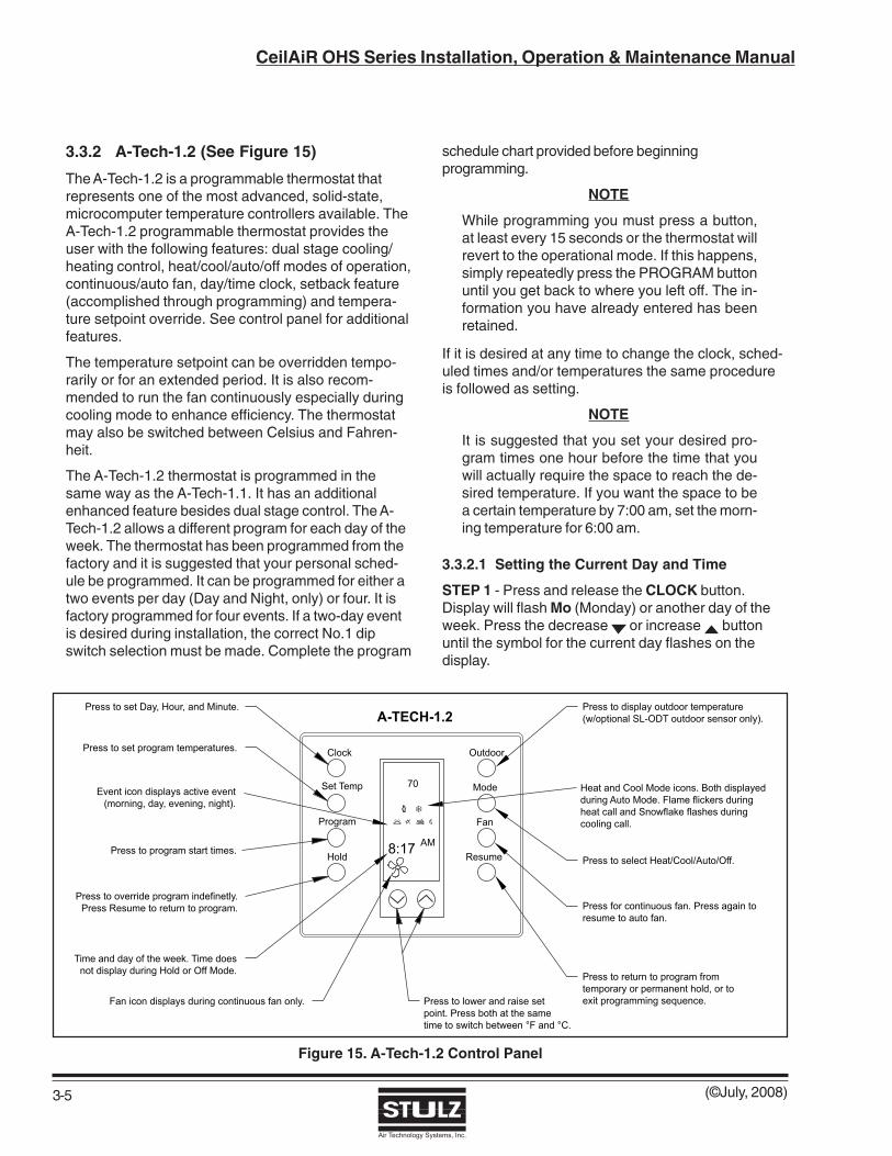
(©July, 2008)
CeilAiR OHS Series Installation, Operation & Maintenance Manual
Air Technology Systems, Inc.
3.3.2 A-Tech-1.2 (See Figure 15)
The A-Tech-1.2 is a programmable thermostat thatrepresents one of the most advanced, solid-state,microcomputer temperature controllers available. TheA-Tech-1.2 programmable thermostat provides theuser with the following features: dual stage cooling/heating control, heat/cool/auto/off modes of operation,continuous/auto fan, day/time clock, setback feature(accomplished through programming) and tempera-ture setpoint override. See control panel for additionalfeatures.
The temperature setpoint can be overridden tempo-rarily or for an extended period. It is also recom-mended to run the fan continuously especially duringcooling mode to enhance efficiency. The thermostatmay also be switched between Celsius and Fahren-heit.
The A-Tech-1.2 thermostat is programmed in thesame way as the A-Tech-1.1. It has an additionalenhanced feature besides dual stage control. The A-Tech-1.2 allows a different program for each day of theweek. The thermostat has been programmed from thefactory and it is suggested that your personal sched-ule be programmed. It can be programmed for either atwo events per day (Day and Night, only) or four. It isfactory programmed for four events. If a two-day eventis desired during installation, the correct No.1 dipswitch selection must be made. Complete the program
schedule chart provided before beginningprogramming.
NOTE
While programming you must press a button,at least every 15 seconds or the thermostat willrevert to the operational mode. If this happens,simply repeatedly press the PROGRAM buttonuntil you get back to where you left off. The in-formation you have already entered has beenretained.
If it is desired at any time to change the clock, sched-uled times and/or temperatures the same procedureis followed as setting.
NOTE
It is suggested that you set your desired pro-gram times one hour before the time that youwill actually require the space to reach the de-sired temperature. If you want the space to bea certain temperature by 7:00 am, set the morn-ing temperature for 6:00 am.
3.3.2.1 Setting the Current Day and Time
STEP 1 - Press and release the CLOCK button.Display will flash Mo (Monday) or another day of theweek. Press the decrease or increase buttonuntil the symbol for the current day flashes on thedisplay.
Figure 15. A-Tech-1.2 Control Panel
3-5

(©July, 2008)
CeilAiR OHS Series Installation, Operation & Maintenance Manual
Air Technology Systems, Inc.
3-6
STEP 2 - Press and release the CLOCK button again.Display will flash the hour (12: _ _) and (AM) or (PM).Press the decrease or increase button until thecurrent hour appears on the display with proper (AM)or (PM) designation.
STEP 3 - Press and release the CLOCK button.Display will flash minutes (:00). Press the decrease or increase button until current minutes appear onthe display.
STEP 4 - Press CLOCK button again. Clock is nowset and the current time will appear on the display.
3.3.2.2 Setback Feature - Setting theProgram Times
STEP 1 - Press and release the PROGRAM button.Mo or current day will flash on display along with
either the morning or the day event symbol.
STEP 2 - Press the decrease or increase buttonuntil the display shows the day of the week you wishto start programming.
STEP 3 - Press and release the PROGRAM button.The hour (12: _ _) and (AM) or (PM) will flash. Pressthe decrease or increase button until the displayshows the desired start hour for event.
STEP 4 - Press and release the PROGRAM button.The minutes (:00) will flash. Press the decrease orincrease button until the display shows the desiredstart minutes for event (program times are set in 10minute increments).
STEP 5 - Press and release the PROGRAM button.The next event of the day will appear and the hourand (AM) or (PM) will flash.
STEP 6 - Repeat steps 2 through 4 for each event ofthe day. (Number of events determined during utilityconnection.)
STEP 7 - Press and release the PROGRAM button.The word COPY and the day just programmed willappear on the display. If the schedule is the same forconsecutive days, press the decrease or increase
button to add days to the display. (This preventshaving to program same times repeatedly or continueto step 8 to program the next day.)
STEP 8 - Press and release the PROGRAM button tocontinue to the next day to be programmed. Repeatsteps 2 through 6 for each day.
3.3.2.3 Setting Heating Temperatures
STEP 1 - Press and release the MODE button until the
word HEAT and the heating symbol and either
morning or the day event symbol appearson the display.
STEP 2 - Press and release SET TEMP button. Theevent symbol (morning or day) along with a flashingtemperature will appear on display.
STEP 3 - Press the decrease or increase buttonuntil the display shows the desired temperature forthe event displayed. Then press and release SETTEMP button.
STEP 4 - Repeat steps 2 and 3 for each event.
3.3.2.4 Setting Cooling Temperatures
The cooling temperature must be set at least twodegrees higher than the heating temperature. Ex-ample: if the heating temperature has been set at70°F, the cooling temperature must be set at 72°F orhigher. If you attempt to set the cooling temperaturecloser than two degrees above the heating tempera-ture, the thermostat will automatically maintain a two-degree separation between heating and cooling, thuslowering the heating temperature.
Setting the cooling temperatures is identical to settingheating temperatures except in STEP 1 the wordCOOL and the cooling symbol R needs to appear onthe display along with event of the day.
3.3.2.5 Reviewing the Scheduled Times
To review your programmed schedules, repeatedlypress the PROGRAM button. Each scheduled eventwill be displayed, starting with the temperature, day,hour and minute for each day of the week. When yourreview is complete, simply press and release theRESUME button.
3.3.2.6 Reviewing Your ProgrammedTemperatures
To review your programmed temperatures, repeatedlypress the SET TEMP button. The display will startflashing and change each time the button is pressedto show the Mode, Event and the Temperature se-lected.
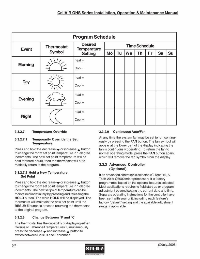
(©July, 2008)
CeilAiR OHS Series Installation, Operation & Maintenance Manual
Air Technology Systems, Inc.
3.3.2.7 Temperature Override
3.3.2.7.1 Temporarily Override the SetTemperature
Press and hold the decrease or increase buttonto change the room set point temperature in 1-degreeincrements. The new set point temperature will beheld for three hours, then the thermostat will auto-matically return to the program.
3.3.2.7.2 Hold a New TemperatureSet Point
Press and hold the decrease or increase buttonto change the room set point temperature in 1-degreeincrements. The new set point temperature can bemaintained indefinitely by pressing and releasing theHOLD button. The word HOLD will be displayed. Thethermostat will maintain the new set point until theRESUME button is pressed returning the thermostatto the original program.
3.3.2.8 Change Between °F and °C
The thermostat has the capability of displaying eitherCelsius or Fahrenheit temperatures. Simultaneouslypress the decrease and increase button toswitch between Celsius and Fahrenheit.
3.3.2.9 Continuous Auto/Fan
At any time the system fan may be set to run continu-ously by pressing the FAN button. The fan symbol willappear at the lower part of the display indicating thefan is continuously operating. To return the fan tonormal operating mode, press the FAN button again,which will remove the fan symbol from the display.
3.3.3 Advanced Controller(Optional)
If an advanced controller is selected (C-Tech-10, A-Tech-20 or C6000 microprocessor), it is factoryprogrammed based on the optional features selected.Most applications require no field start-up or programadjustment beyond setting the current date and time.Separate operating instructions for the controller havebeen sent with your unit, including each feature’sfactory "default" setting and the available adjustmentrange, if applicable.
3-7
Program Schedule
Morning
Day
Evening
Night
Event ThermostatSymbol
DesiredTemperature
Setting Mo Tu We Th Fr Sa Su
Time Schedule
heat =
Cool =
heat =
Cool =
heat =
Cool =
heat =
Cool =

(©July, 2008)
CeilAiR OHS Series Installation, Operation & Maintenance Manual
Air Technology Systems, Inc.
4-1
4.0 Maintenance
4.1 Periodic General Maintenance
Systematic, periodic general maintenance of theCeilAiR unit is recommended for optimum systemperformance. General maintenance should include,but is not limited to, the following: replacing filters andhumidifier cylinders, tightening electrical connections,checking the condensate line to ensure it is free ofdebris, cleaning the interior of the unit, inspecting theunits' components visually, checking belt tension,checking level of refrigerant and ensuring no moisturein the refrigerant.
Use copies of the Periodic General MaintenanceChecklist in this manual (see Appendix A) to recordperiodic general maintenance inspections. Forassistance, contact the SATS Product Support Group.Ensure to adhere to all safety statements whileperforming any type of maintenance.
WARNING This equipment should be serviced and repairedby a journeyman or a qualified refrigeration tech-nician only.
WARNING Turn off power to unit at the service disconnectswitch unless you are performing tests that re-quire power. With power and controls energized,unit could begin operating automatically at anytime.
Hazardous voltage will still be present at evapo-rator, condenser, heat/reheat and humidifier,even with the unit turned off at the control panel.To isolate unit for maintenance, turn off powerat non-fused service switch.
Always disconnect main power prior to perform-ing any service or repairs. To prevent personalinjury, stay clear of rotating components be-cause automatic controls may start themunexpectedly.
WARNING This unit employs high voltage equipment withrotating components. Exercise extreme care toavoid accidents and ensure proper operation.
WARNING Phosgene, a deadly, poisonous gas, is gener-ated when refrigerant is exposed to flame. Al-ways ensure adequate ventilation during refrig-eration repairs.
Always recover all refrigerant prior to any sys-tem repairs, failure to do so may result in sys-tem over pressurization and rupture.
4.1.1 Precision A/C Unit
4.1.1.1 FilterThe filter is usually the most neglected item in an airconditioning system. To maintain efficient operation,the filter should be checked at least monthly andreplaced as required.
NOTE
Conditions of spaces vary and filters should bechecked based on those conditions.
4.1.1.2 BlowerThe blower motor is provided with permanently lubri-cated bearings and should not require lubrication forthe lifetime of the equipment. Periodic checks of theblower system should include checking the wiring,blower motor mounts, housing bolts and blower wheel.Ensure all electrical connections are tight. Check thatall mounts are secure and the blower wheel is tightlymounted on the shaft and does not rub against the fanhousing. The blower vanes should be kept free ofdebris.
4.1.1.3 CoilsThe coil(s) should be inspected semi-annually andcleaned as required following standard coil cleaningpractices. Using a brush, clean fluid coil fins of all debristhat will inhibit airflow. This can also be done withcompressed air or with a commercial coil cleaner. Checkfor bent or damaged coil fins and repair as necessary.Check all refrigerant lines and capillaries for vibrationisolation and support if necessary. Check all piping forsigns of leaks.
Inspect electric heating elements to ensure they are freeof debris semiannually.
4.1.1.4 Drain PanTo assure proper drainage, inspect the drain panregularly. Make sure the drain pan outlet is always freeof debris and ensure drain pan does not leak.

(©July, 2008)
CeilAiR OHS Series Installation, Operation & Maintenance Manual
Air Technology Systems, Inc.
4.1.1.5 Condensate Pump
The optional condensate pump should be inspectedsemiannually and cleaned. Ensure that the float worksfreely. Wipe the float with a wet cloth and detergent toremove dirt. Clean the tank bottom. Check that thedischarge line is open and water can pass through itfreely.
4.1.1.6 Humidifier
The optional humidifier’s steam cylinder has a limitedlifetime and must be replaced periodically. Becausewater conditions and humidifier usage rates varygreatly, it is difficult to establish intervals for changingthe cylinder. Individual maintenance schedules mustbe determined for each location, based upon periodicexamination of the humidifier. A change cylinder lighton the humidifier cabinet will illuminate (red) when thecylinder requires replacement.
NOTEThe red light may illuminate during initial start-up but it doesn’t necessarily mean the cylinderneeds to be replaced.
Refer to the humidifier operator’s manual suppliedunder separate cover for detailed instructions forchanging the cylinder.
4.1.2 Condensing Unit
Maintenance access to the condensing unit is throughone or two removable panels (depending on model).Clean the air-cooled condenser coil of all debris thatwill inhibit airflow. This can be done with compressedair or with a commercial coil cleaner. Check for bent ordamaged coil fins and repair as necessary. On outdoorunits in winter, do not permit snow to accumulate on oraround the condensing unit. Check all refrigerant linesand capillaries for vibration isolation and support asnecessary. Check all refrigerant and coolant lines forsigns of leaks.
CAUTION The compressor crank case heater is energizedas long as power is applied to the unit. If themain switch is disconnected for long periodsdo not attempt to start a condensing unit until 8hours after applying power. This allows enoughtime for all liquid refrigerant to be driven out ofthe compressor. This is especially important atlow ambient conditions.
SYMPTOM PROBABLE CAUSE RECOMMENDATION
Suction Pressure Too Low a. Loss of refrigerant Locate leak and repair.(bubbles in sight glass). Recharge system.
b. Expansion valve stuck or Remove and clean or replace valve.obstructed (short cycle or continuousrunning).
c. Clogged drier/strainer (feels cold). Replace with new drier/strainer.
d. Dirty air filters. Clean/replace filters.
Chilled Water Valve Fails a. Thermostat set too high. Adjust to correct temperature setting.to Open or Close
b. No control power to the chilled water Thermostat wired incorrectly. Check valve. wiring diagram and rewire if required.
c. Actuator failed. Replace actuator.
Evaporator Coil Ices a. Low airflow. 1. Check filters. Replace as needed.
4-2
4.2 Troubleshooting
Turn off all power to the unit before conducting any troubleshooting procedures unless the procedure specifi-cally requires the system to operate. Keep hands, clothing and tools clear of the electrical terminals androtating components. Equipment located in the ceiling can pose unusual difficulties. Ensure that your footingis stable at all times.

(©July, 2008)
CeilAiR OHS Series Installation, Operation & Maintenance Manual
Air Technology Systems, Inc.
4-3
SYMPTOM PROBABLE CAUSE RECOMMENDATION
Evaporator Coil Ices (Cont.) 2. Check for and clear any obstructions across or in the (supply)discharge airstream.
3. Check correct rotation ofevaporator blower.
b. Temperature setting Increase temperaturetoo low (68°F min.). setpoint.
c. Discharge air short cycling back Check discharge grille orientation. to return.
d. Low refrigerant charge. Find leak, repair and rechargesystem.
Blower Fails to Start a. Power failure. Check main voltage power sourceinput cable.
b. Control transformer circuit breaker Check for short circuit or groundtripped. fault; if none, reset circuit breaker.
c. Defective contactor. Repair or replace.
d. Condensate switch open. 1. Ensure unit is level.
2. Check that condensate pan isdraining properly. Clear obstructions.
e. Thermal overload tripped. Reset overload and check amperageof motor. Compare to setting onoverload and adjust to FLA. All direct-drive motors are internally protectedand do not require overload.
Control is Erratic Wiring - improperly connected or broken. Check wiring against schematicdiagram.
Condenser Pressure a. Non-condensable gas or air in Recover system and recharge. Installtoo High the system. new drier/strainer.
b. Condenser air intake is blocked. Remove debris and clean condenser.
c. Overcharge of refrigerant. Reclaim excess refrigerant fromsystem.
d. Low water flow to water-cooled Reset-determine cause and fix.condenser.
e. Condenser fan not operating. Check pressure/temperature operating switches and motor.Replace as needed.
f. Water/glycol temperature too high. Check flow and operation ofdrycooler.
g. Condenser pressure regulating Adjust to obtain correct pressure.valve setting too high.
h. Flow of water/glycol too low. 1. Check glycol solution level andconcentration.

(©July, 2008)
CeilAiR OHS Series Installation, Operation & Maintenance Manual
Air Technology Systems, Inc.
SYMPTOM PROBABLE CAUSE RECOMMENDATION
Condenser Pressure Too High 2. Valves not open or partially open.(Cont.) Repair/replace as needed.
3. Air in system - bleed system.
4. Check all strainers and clean ifneeded.
i. Water/glycol solution not mixed prior Remove solution and premix.to adding to system. Refill system.
Condenser Pressure a. Loss of refrigerant (indicated by Locate and repair leak. Rechargetoo Low bubbles in sight glass). system.
b. Condenser fan controls not set Adjust or repair controls.properly.
c. Water regulating valve adjusted Readjust to 240-250 psig.too low.
Noisy Compressor a. Expansion valve stuck in open Ensure feeder bulb is tight on suctionposition (abnormally cold suction line). line. Check operation and superheat.
b. Broken compressor valve Replace compressor.(compressor knocking, suctionpressure rises faster than 2lbs/minafter shutdown).
c. Worn or scarred compressor bearings. Replace compressor.
d. Liquid slugging. System overcharged.Reclaim excess refrigerant.
e. Scroll compressor not properly Phase correctly at main powerphased. source. DO NOT REWIRE
COMPRESSOR.
Compressor Fails to Start a. Thermostat set too high. Adjust to desired temperature.
b. Compressor internal protector Check compressor for short circuitis open. or ground.
c. Complete loss of refrigerant charge Locate and repair leak. Recharge(low pressure safety switch). system.
d. Condenser pressure too high (high Check condenser for obstructions.pressure safety switch).
System Short of Capacity a. Low refrigerant (indicated by Check for leaks Repair andbubbles in sight glass). recharge system.
b. Expansion valve stuck or obstructed Remove valve and clear obstruction(short cycling or continuous running). or replace valve.
c. Clogged drier/strainer (feels cold). Replace with new drier/ strainer.
d. Reduced airflow. and evaporator Check belt tension, filters.coil.
4-4

(©July, 2008)
CeilAiR OHS Series Installation, Operation & Maintenance Manual
Air Technology Systems, Inc.
4-5
SYMPTOM PROBABLE CAUSE RECOMMENDATION
Compressor Short Cycles a. Low line voltage causing Check power source for cause oflowcompressor to overheat. line voltage.
b. Dirty or iced over evaporator coil. Defrost and/or clean coil.
c. Reduced airflow. (when applicable). Check filter and belt tension.
d. Lack of refrigerant. Check for leak. Repair andrecharge system.
e. Short cycling of conditioned air. 1. Supply and/or return grilles areincorrectly oriented. Re-orient.
2. Supply and return grilles are tooclose together. Move further apart.
3. Insufficient heat load. Add temporary heat load to compensate.
f. Thermostat is improperly located. Check for supply registers that maybe too close to thermostat. Relocateif necessary.
Heater Inoperative a. Fuses blown. Check for short circuit, replace fuse.
b. Thermostat set too low. Increase temperature setpoint.
c. Overheat switch open. Insufficient airflow across heater elements. Check for dirty filters orobstructions that may reduce airflow. Correct or replace as needed.
d. Fuse link blown. Replace fuse link (See itemimmediately above).
e. Heater element burned out. Check continuity with an ohmmeter.Replace heater element.
Humidifier Inoperative a. Water supply has been turned off Connect and/or turn on water supply.Note: See Humidifier Manual or not connected.For Additional Help.
b. Electrical connections are loose. Tighten electrical connections.
c. Humidifier fuses are blown. Check for over current by thehumidifier electrodes. Drain waterfrom tank and refill. Replace fuses.
d. Relative humidity is above set point. Adjust humidistat setpoint.
e. Electrode canister change cylinder 1. Consult humidifier manual.light is on.
2. Water conductivity is too low andwater is at the top of the cylinder (seenext item).
f. Water conductivity is too low. Add a teaspoon of table salt to thewater through the top of the cylinder.Typically only required on initial start-up.

(©July, 2008)
CeilAiR OHS Series Installation, Operation & Maintenance Manual
Air Technology Systems, Inc.
4.3 Field Service
NOTE
Do not attempt to make repairs without theproper tools.
It may be necessary to perform repairs on the refrig-eration system. If field repairs are necessary, thefollowing procedures apply:
1. Ensure all electrical connections are tight.
2. Check all fuses, contacts and wiring. Contactorsshould be replaced if contacts are worn or pitted.
4.3.1 Leak Detection
Several methods can be used to detect a leak in therefrigeration system. The most modern and easiestmethod is to use an electronic leak detector. Follow themanufacturer’s directions and any leak can be quicklylocated. A second method is to use soap bubbles.Apply a solution of soapy water with a brush or spongeto the joints and connections in the refrigeration lines. Aleak in the lines will cause bubbles to form.
NOTE
Halogen leak detectors are inefective withR407C refrigerant because unlike R22 refriger-ant, R407C does not contain chlorine.
4.3.2 Leak Repair
When a leak is located, properly reclaim the remainingrefrigerant charge before beginning repairs. Adjacentpiping must be thoroughly cleaned by removing allpaint, dirt and oily film. Use a wire brush, sandcloth orsandpaper and wipe the area with clean, dry cloths.Protect nearby parts from heat damage by wrappingwith water-soaked cloths.
4.3.3 Refrigerant Piping
When replacing components within the cabinet of theunit the following consumable materials are recom-mended. Use Silfos alloy for copper-to-copper (pipingdischarge or suction line repairs). Silver solder (Stay-Silv #45) and flux are to be used on copper-to-brassor copper-to-steel repairs. For liquid line repairs at thedrier, strainer, sight glass, or expansion valve, use a95 % tin to 5 % antimony solder with flux.
When component replacement is complete, remove alltraces of flux. After any repair, pressure check thesystem to check for leaks prior to recharging thesystem.
4.3.4 General Common Repairs/ComponentReplacement
4.3.4.1 Compressor Failure
The compressor is the most important component ofthe air conditioner. Numerous safety devices areprovided to protect the compressor from failing.
If a compressor failure has occurred, determinewhether it is an electrical or a mechanical failure. Anelectrical failure will be indicated by the distinctpungent odor once the system has been opened. If aburnout has occurred, the oil will be black and acidic.A mechanical failure will have no burned odor and themotor will attempt to run, an abnormal or excessivenoise may be present.
An analysis of the oil is the only way to ensure theproper procedure for cleaning the refrigerant system.Acid test kits are available from several manufacturersfor measuring the acid level in the oil. These arecapable of making quite accurate acid measurements,but if they are not available, a check of the oil by sightand smell can give a quick indication if contaminationremains in the system. Since refrigeration oil varies incolor, a sample of the new oil in the replacementcompressor should be removed prior to installation andsealed in a small glass bottle for comparison pur-poses. If the oil has been exposed to refrigerant, thebottle should not be tightly capped, since the residualrefrigerant may create a high pressure if tightly sealedand exposed to high temperature.
All electrical connections should be checked to besure that they are tight and properly made. Check allfuses, contactors and wiring. The contactor should beexamined and replaced if contacts are worn or pitted.
If there is acid in the oil, there has been an electricalfailure which has caused the compressor motor toburn out. The acid diffuses throughout the refrigerationsystem and must be removed by using a burnout filterkit before a new compressor is placed in service. Notonly must the compressor be replaced, but also theentire refrigeration circuit must be cleaned of theharmful contaminants left by the burnout. See section4.3.4.3 (Burn-Out/Acidic Cleanup) for the properprocedure.
If there is no acid in the oil, there has been a mechani-cal failure. See section 4.3.4.2 (Standard Cleanout) forthe proper cleaning procedure.
4-6
(©July, 2008)
CeilAiR OHS Series Installation, Operation & Maintenance Manual
Air Technology Systems, Inc.
4-7
CAUTION Damage to a replacement compressor causedby improper system cleaning constitutes abuseunder the terms of the warranty. This will VOIDTHE COMPRESSOR WARRANTY. Always con-sult the factory prior to replacing the compressor.
CAUTION POE oil is used in systems with R-407C refriger-ant. If a replacement compressor is provided, en-sure that it is filled with POE oil before installing.
4.3.4.2 Standard Cleanout Procedure
CAUTION Avoid touching or contacting the gas and oil withexposed skin. Severe burns will result. Use longrubber gloves in handling contaminated parts.
NOTE
Cleaning operations must be performed by a jour-neyman, refrigeration mechanic, or air condition-ing technician.
1. Turn off power to unit at the main power discon-nect switch.
2. Remove the old compressor and install the newcompressor.
3. Remove the liquid line drier and install an over-sized liquid line filter-drier (one size larger than thenormal selection size).
4. Evacuate the system according to standardprocedures. Normally, this will include the use of ahigh-vacuum pump and a low-vacuum microngauge for measuring the vacuum obtained.
5. Recharge the system.
6. Turn on the power at the main power disconnectswitch and start the system.
4.3.4.3 Burn-Out/Acidic Cleanup Procedure
NOTE
Cleaning operations must be performed by a jour-neyman, refrigeration mechanic, or air condition-ing technician.
1. These systems should be cleaned using thesuction line filter-drier method.
2. Turn off power to the unit at the main powerdisconnect switch.
3. Remove the burned-out compressor and install thenew compressor.
4. Install a suction line filter-drier designed for acidremoval.
5. Remove the liquid line drier and install an over-sized liquid line filter-drier (one size larger than thenormal selection size).
6. Check the expansion valve, sight glass and othercontrols to see if cleaning or replacement isrequired.
7. Evacuate the system according to standardprocedures. Normally, this will include the use of ahigh-vacuum pump and a low-vacuum microngauge for measuring the vacuum obtained.
8. Recharge the system through the access valve onthe suction line filter-drier.
9. Turn on power at the main power disconnectswitch and start the system.
10. The permanently installed suction line filter-drierpermits small-system cleanup to be completed inone service call. The pressure drop across thesuction line filter-drier should be measured duringthe first hour of operation. If the pressure dropbecomes excessive, the suction line filter-driershould be replaced (See Sporlan Bulletin 40-10, forthe maximum recommended pressure drop (PSI)for the suction line filter drier).
11. In 24 hours, take an oil sample. Observe the colorand test for acidity. If the oil is dirty or acidic,replace the suction line filter-drier.
12. In 2 weeks, examine oil to determine if anothersuction line filter-drier change is necessary.
4.3.4.4 Humidifier Cylinder Replacement
After an extended period of operation, a red light willilluminate on the humidifier cabinet indicating that thecylinder is completely used and a replacementcylinder must be installed. The cylinder is disposableand cylinder life is dependent on water supply condi-tions and humidifier usage. The following proceduresare to be followed when replacing the cylinder.
CAUTION Failure to replace the cylinder at the end of cyl-inder life may result in humidifier damage.

(©July, 2008)
CeilAiR OHS Series Installation, Operation & Maintenance Manual
Air Technology Systems, Inc.
4-8
NOTEDecrease the humidity setpoint below ambienthumidity to allow the cylinder to cool down be-fore removing the cylinder.
1. Turn off water supply to the humidifier.
2. Drain the cylinder by pushing the “Auto/On-Off/Drain” switch to the “Drain” position.
3. When drained, push the “Auto/On-Off/Drain”switch to the “Off” position.
4. Disconnect power at the main power disconnectswitch.
5. The power wires to the cylinder are attached bycylinder plugs to the electrode pins on top of thecylinder. Pull these plugs vertically off the pins.
CAUTION The cylinder and steam hose may be hot andburns may result.
6. Loosen the steam hose clamp(s) and pull thesteam hose off vertically.
7. Lift the cylinder straight up to disengage it fromthe humidifier.
8. Place the new cylinder on the side mounting slotswithin the unit, ensuring the cylinder mountingstubs are seated properly.
9. Replace the cylinder plugs on the pins, ensuringthe white sensor plug goes on the single pin,which is offset from the others.
10. Ensure the plugs are secured on the pins. If theplugs are loose, they may be temporarilysqueezed together, however the plugs must bereplaced since a loose plug could generateenough heat to melt and destroy the plug.
11. Replace the steam hose and tighten the clamp(s).
12. Turn on main power at the main power disconnectswitch.
13. Push the “Auto/On-Off/Drain” switch to the “Auto/On” position.
14. Turn on the water supply to the humidifier.
15. Readjust the humidity setpoint.
If the humidifier is to be shut down for an extendedperiod, always drain the cylinder first. Follow theabove steps (1 through 4) ensuring the “Auto/On-Off/Drain” switch is in the “Off” position. Failure to do thiswill drastically shorten the cylinder life.
4.3.4.5 Filter Replacement
The filters are located either internal or external to thecabinet depending on the configuration of the unit.Regardless of location, the filter is accessed throughan access panel, which is labeled "FILTER ACCESS".Remove access panel and old filter. Ensuring direc-tional airflow arrows on filter are correct, insert newfilter and replace the access panel.

(©July, 2008)
CeilAiR OHS Series Installation, Operation & Maintenance Manual
Air Technology Systems, Inc.
5-1
5.0 Product Support GroupSATS provides to its customers a Product SupportGroup (PSG) which not only provides technical supportand parts but the following additional services, asrequested: performance evaluations, start-up assis-tance and training.
5.1 Technical Support
The SATS Product Support Group (PSG) is dedicatedto the prompt reply and solution to any problemencountered with a unit. Should a problem develop thatcannot be resolved using this manual, you maycontact PSG at (240) 529-1399 Monday throughFriday from 8:00 a.m. to 5:00 p.m. EST. If a problemoccurs after business hours, dial the page number(301) 414-4514 and follow the steps below:
1. Wait for the dial tone.
2. Dial your telephone number (including area code).
3. Press the pound (#) key.
4. Wait for a busy signal.
5. Hang up the telephone.
One of our service technicians will return your call.When calling to obtain support, it is vital to have thefollowing information readily available, (information isfound on unit's nameplate):
• Unit Model Number (OHS-XXX-XX-X)
• SATS Item Number (123456)
• Unit Serial Number (1234567)
• Description of Problem
5.2 Obtaining Warranty Parts
Warranty inquires are to be made through the ProductSupport Group (PSG) at (240) 529-1399 Mondaythrough Friday from 8:00 a.m. to 5:00 p.m. EST. Aservice technician at SATS will troubleshoot thesystem over the telephone with a field service techni-cian to determine the defect of the part. If it is deter-mined that the part may be defective a replacementpart will be sent UPS ground. If the customer requeststhat warranty part(s) be sent by any other method thanUPS ground the customer is responsible for theshipping charges. If you do not have established creditwith SATS you must provide a freight carrier accountnumber.
A written (or faxed) purchase order is required onwarranty parts and must be received prior to 12:00p.m. for same day shipment. The purchase order mustcontain the following items:
• Purchase Order Number
• Date of Order
• SATS Stated Part Price (obtained from PSG)
• Customer Billing Address
• Shipping Address
• Customer's Telephone and Fax Numbers
• Contact Name
• Unit Model No., Serial No. & SATS Item No.
The customer is responsible for the shipping costincurred for returning the defective part(s) back toSATS. Return of defective part(s) must be within 30days at which time an evaluation of the part(s) isconducted and if the part is found to have a manufac-turing defect a credit will be issued.
When returning defective part(s) complete the ReturnMaterial Authorization Tag and the address labelreceived with the replacement part.
See SATS Standard Warranty located in section oneof this manual.
5.3 Obtaining Spare/Replacement Parts
Spare and replacement parts requests are to be madethrough the Product Support Group (PSG) by fax (301)620-1396, telephone (240) 529-1399 or E-mail([email protected]). Quotes are given for specifiedlisted parts for a specific unit.
SATS accepts Visa and MasterCard. SATS mayextend credit to its customers; a credit applicationmust be prepared and approved (this process couldtake one week).
A 25% minimum restocking charge will be applied onreturned stocked parts that were sold as spare/replacement parts. If the returned part is not a stockeditem, a 50% restocking charge may be applied.Additionally a Return Material Authorization Number isrequired when returning parts. To receive credit forreturned repair/replacement parts, the parts must bereturned to SATS within 30 days of the purchase date.Spare part sales over 30 days old will be consideredfinal and the parts will remain the sole property of theordering party.

(©July, 2008)
CeilAiR OHS Series Installation, Operation & Maintenance Manual
Air Technology Systems, Inc.
NOTES

(©July, 2008)
CeilAiR OHS Series Installation, Operation & Maintenance Manual
Air Technology Systems, Inc.
Appendix A - Forms
Checklist for Completed Installation
1 Proper clearances for service access havebeen maintained around equipment.
2 Equipment is level and mounting fasteners (ifapplicable) are tight.
3 Piping completed to refrigerant or coolant loop(if required).
4 All field installed piping leak tested.
5 Refrigerant charge added (if required).
6 Condensate pump installed (if required).
7 Condensate drain line connected.
8 Water supply line connected to humidifier. If amanual cut-off valve is installed, open valve.
9 Humidifier “On/Off/Auto/Drain” switch is in the“Auto” position.
10 Safety pan installed under ceiling mountedequipment (if required).
11 Filter box installed (if required).
12 Filter (s) installed (if required).
13 Duct work completed or optional plenuminstalled (if required).
14 Incoming line voltage matches equipmentnominal nameplated rating ± tolerances.
15 Main power wiring connections to the equip-ment, including earth ground, have beenproperly installed.
16 Customer supplied main power circuit breaker(HACR) type or fuses have proper ratings forequipment installed.
17 All wiring connections are tight.
18 Control wiring connections completed toevaporator unit and condenser/condensing unit(if required), including wiring to wall mountedcontrol panel and optional controls.
19 Foreign materials have been removed frominside and around all equipment installed(shipping materials, construction materials,tools, etc.).
20 Fans and blowers rotate freely by hand withoutunusual noise.
21 Inspect all piping connections for leaks duringinitial operation.
A-1
Frederick, Maryland USA 21704Air Technology Systems, Inc.
OHS Series Precision Air Conditioner Telephone: (301) 620-2033Facsimile: (301) 620-1396

(©July, 2008)
CeilAiR OHS Series Installation, Operation & Maintenance Manual
Air Technology Systems, Inc.

(©July, 2008)
CeilAiR OHS Series Installation, Operation & Maintenance Manual
Air Technology Systems, Inc.
A-2
OHS Series Precision Air Conditioner Telephone: (301) 620-2033Facsimile: (301) 620-1396
Periodic General Maintenance Checks and Services Checklist
Date: ____________________________ Prepared By: ___________________________
Model Number: ____________________________ Serial Number: __________________________
Item Number: ____________________________
MonthlyFilters Blower Section Condensate Drain
Cleanliness Blower Turns Drain is OpenNo Obstructions Belts (if applicable) Condensate Pan Safety
Switches Operate Freely
MiscellaneousCheck Glycol or Chilled water for Air (bleed as required)External Heat Exchanger Clean and Clear of ObstructionsHumidifier Cylinder and Controls Operate Properly
Semi-Annually
Check Refrigerant Charge (bubbles in sight glass) Tighten Electrical Connections
Check Suction & Discharge Pressure Check Contacts on Contactors
for Pitting
Check Glycol Solution Concentration in System Clean Unit as Necessary
Clean Coils Test the Glycol Solution
Inhibitors (flush if necessary)
Heat/Reheat Operational Clean Condensate Pump
Annually
Refrigerant Systems Chilled Water SystemsInspect Glycol System for Leaks and Corrosion Inspect Chilled Water System
for Leaks and CorrosionConduct a Complete Check of All Services Listed Conduct a Complete Check ofAbove and Clean Unit's Interior All Services Listed Above and
Clean Unit's Interior
Notes:____________________________________________________________________________________________________________________________________________________________________________________________________________________________________________________________________________________________________________________________________________________________________________________________________________________________________________________________________________________________________________________________________________________________________________________________________________________________________________________________________________________________________________________________________________________________________________________________________________________________________________________________________________________________________________________________________________________________________________________________________________________________________________________________________________________________________________________________________________
Signature:________________________________
*** If factory assistance is required for any reason, provide the model number, serial number, and SATS itemnumber found on the unit nameplate. This will speed the process and ensure accuracy of information. ***
Air Technology Systems, Inc. Frederick, Maryland USA 21704

(©July, 2008)
CeilAiR OHS Series Installation, Operation & Maintenance Manual
Air Technology Systems, Inc.

(©July, 2008)
CeilAiR OHS Series Installation, Operation & Maintenance Manual
Air Technology Systems, Inc.
Appendix B – Glossary
Definition of Terms and Acronyms
SATS - Stulz Air Technology Sytstems, Inc. MCA - Minimum Circuit Ampacity
BTU/Hr - British Thermal Units Per Hour MSDS - Material Safety Data Sheet
CFM - Cubic Feet Per Minute NEC - National Electric Code
CNDCT - Conductor NFPA - National Fire Protection Agency
ESD - Electrostatic Discharge OHS - Overhead System
º F - Degrees Fahrenheit PH - Phase
FLA - Full Load Amps PSG - Product Support Group
FOB - Freight on Board PSI - Pounds Per Square Inch
HACR - Heating, Air Conditioning, Refrigeration PSIG - Pounds Per Square Inch Gauge
HP - Horse Power RLA - Rated Load Amps
Hz - Hertz R-Value - Thermal Resistance
IAQ - Indoor Air Quality R22 - Refrigerant (HCFC-22)
in. w.g. - Inches of Water Gauge R407C - Blended Refrigerant
KVA - Kilo Volt Amp SPDT - Single Pole, Double Throw
kW - Kilowatts TEV - Thermal Expansion Valve
LRA - Locked Rotor Amps V - Volt
MAX FUSE - Maximum Fuse VAC - Volt, Alternating Current
B-1

(©July, 2008)
CeilAiR OHS Series Installation, Operation & Maintenance Manual
Air Technology Systems, Inc.
OCH0006 REV-