ceiling diffuser - schakoceiling diffuser ida 02/04 - 3 construction subject to change. no return...
TRANSCRIPT
Ferdinand Schad KGSteigstraße 25-27
D-78600 KolbingenTelephone +49 (0) 74 63 - 980 - 0
Fax +49 (0) 74 63 - 980 - [email protected]
Ceiling DiffuserIDA
Contents
Construction subject to change. No return possible!
Ceiling Diffuser IDA
02/04 - 2 20.09.2019Version:
Description ........................................................................................................................................3Construction .............................................................................................................................................................................. 3Model ......................................................................................................................................................................................... 3Accessories ................................................................................................................................................................................ 3Fastening ................................................................................................................................................................................... 4Quick selection ........................................................................................................................................................................... 4Smoke test ................................................................................................................................................................................. 4
Models and dimensions .........................................................................................................................5Dimensions ................................................................................................................................................................................ 5Dimensions of accessories ........................................................................................................................................................ 7Fastening methods ..................................................................................................................................................................... 8
Technical data .................................................................................................................................. 10Pressure loss and noise level ................................................................................................................................................... 10Maximum end velocity of jet .................................................................................................................................................... 13Critical throw ........................................................................................................................................................................... 14Maximum penetration .............................................................................................................................................................. 15Temperature and induction ratios ............................................................................................................................................ 16Connection diagrams of electric actuators ............................................................................................................................... 17Technical data of electric actuators .......................................................................................................................................... 17
Legend ........................................................................................................................................... 18IDA order code .................................................................................................................................. 19Order code SK-...-08-... ....................................................................................................................... 20Specification text ............................................................................................................................... 21

Ceiling Diffuser IDA
02/04 - 3
Construction subject to change. No return possible!
20.09.2019Version:
DescriptionElectrically adjustable ceiling diffusers are required for coolingand heating large halls.In order to prevent draughts in the cooling mode, the supply airmust largely be discharged horizontally from the diffuser. How-ever, in heating mode, the diffuser must have high penetrationdepth, in order to achieve fast and efficient heating.The ceiling diffuser type IDA meets both these requirements ide-ally. It ensures optimum air distribution in cooling and heatingmodes. The diffuser consists of an adjustable air guide funneland a front plate. The adjustable air guide funnel is varied man-ually or by means of an electric actuator or a thermocouple insuch a way that a vertical (heating mode) or horizontal (coolingmode) supply air jet is created. When using a thermocouple ad-justment, a vertical supply air jet (heating mode) is created froma supply air temperature of approx. 26° C. At supply air temper-atures < 26° C, a horizontal supply air jet (cooling mode) is cre-ated. A volumetric flow meter can be integrated into the spigotof the plenum box at an extra charge. The measurement error ofthe volumetric flow meter is ± 5 % at a connection spigot veloc-ity of 2-5 m/s and a straight flow pattern of at least 1 x D. Themeasurement is carried out with integrated diffuser. To adjustthe damper, the ceiling diffuser must be removed. Alternatively,a cable-operated adjustment can be ordered at an extra charge,which allows the damper to be adjusted on the room side evenwith mounted diffuser.With the ROB version, the diffuser plate, the damper, if installed,and the volumetric flow meter can be removed from the plenumbox, to allow duct cleaning robots into the ductwork from the roomside.
Construction
Model
Attention!The optimum function of the IDA-Q-Z-... / IDA-R-Z-... can onlybe guaranteed in connection with the original plenum box.
Accessories
Faceplate- made of sheet steel painted to RAL 9010 (white).- made of sheet steel painted to a different RAL colour
(at an extra charge).Air guide funnel
- made of sheet steel painted to RAL 9005 (black)Manual adjustment
- made of galvanised sheet steel with a hexagonal sockethead screw M6 (to DIN EN ISO 4762)
IDA-Q - Square faceplateIDA-R - Round faceplateIDA-...-ZH - for supply air with manually adjustable air guide
funnel, horizontal air throw (cooling mode)IDA-...-ZV - for supply air with manually adjustable air guide
funnel, vertical air throw (heating mode)IDA-...-AA - for return air, without air guide funnel
Plenum box (-SK)- with lateral connection spigot on the box (-S1, standard)- with connection spigot from above (-S0)- with 2 connection spigots offset by 90° (-S2)- with 2 connection spigots offset by 180° (-S3)- with 2 lateral connection spigots next to each other (-S5)
- with air diffuser plate, sheet steel painted to RAL 9005(black) (only for supply air model)
- Housing and connection spigot made of galvanised sheetsteel, inside painted to RAL 9005 (black)
- concealed mounting pole brace made of aluminium paintedto RAL 9005 (black)
- Concealed mounting made of plastic, similar to RAL colour9005 (black) (-VM)
Damper (-DK1)- in connection spigot- Damper made of galvanised sheet steel- Damper fastening made of plastic
Damper (-DK2)- DK1 with cable-operated adjustment
Electric actuator (3-point activation)- 24 V AC (standard)
- without auxiliary switch (-E090)- with 2 integrated auxiliary switches (-E093)
- 230 V AC (-E092)Thermocouple adjustment (-TE01)
- Diffuser adjustment option without electrical energy as afunction of the supply air temperature.
Rubber lip seal (-GD1)- in the plenum box at the connection spigot- Special rubber
ROB version (-ROB1)- removable damper and volumetric flow meter (only possi-
ble for plenum box SK-Q-...)Volumetric flow meter (-VME, available for IDA up to NW625)
- Mounting made of galvanised sheet steel- Measuring sensor made of plastic- Aluminium connections
ball-impact guard (-BS)- only possible for IDA-Q-... with screw mounting and for
NW800 only with concealed mounting. Attention: With re-duced drill pattern, only possible with plenum box in thesame size as the faceplate.
- Steel painted to RAL 9010 (white), other RAL colours pos-sible at an extra charge.
Internal insulation (-Ii)- thermal insulation at the inside of the plenum box
External insulation (-Ia)- thermal insulation at the outside of the plenum box
Ceiling Diffuser IDA
02/04 - 4
Construction subject to change. No return possible!
20.09.2019Version:
Fastening Quick selection
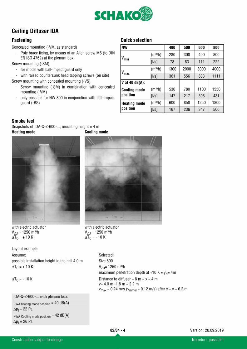
Smoke testSnapshots of IDA-Q-Z-600-..., mounting height = 4 m
Layout example
Concealed mounting (-VM, as standard)- Pole brace fixing, by means of an Allen screw M6 (to DIN
EN ISO 4762) at the plenum box.Screw mounting (-SM)
- for model with ball-impact guard only- with raised countersunk head tapping screws (on site)
Screw mounting with concealed mounting (-VS)- Screw mounting (-SM) in combination with concealed
mounting (-VM)- only possible for NW 800 in conjunction with ball-impact
guard (-BS)
NW 400 500 600 800
Vmin(m³/h) 280 300 400 800
[l/s] 78 83 111 222
Vmax(m³/h) 1300 2000 3000 4000
[l/s] 361 556 833 1111
V at 40 dB(A):
Cooling mode position
(m³/h) 530 780 1100 1550
[l/s] 147 217 306 431
Heating mode position
(m³/h) 600 850 1250 1800
[l/s] 167 236 347 500
Assume: Selected:possible installation height in the hall 4.0 m Size 600ΔTO = + 10 K VZU= 1250 m³/h
maximum penetration depth at +10 K = yH= 4m
ΔTO = - 10 K Distance to diffuser = 8 m = x = 4 m y= 4.0 m -1.8 m = 2.2 mvmax = 0.24 m/s (vmittel = 0.12 m/s) after x + y = 6.2 m
IDA-Q-Z-600-... with plenum box:LWA heating mode position = 40 dB(A)Δpt = 22 PaLWA Cooling mode position = 42 dB(A)Δpt = 26 Pa
Heating mode Cooling mode
with electric actuatorVZU = 1250 m³/hΔTO = + 10 K
with electric actuatorVZU = 1250 m³/hΔTO = - 10 K
Ceiling Diffuser IDA
02/04 - 5
Construction subject to change. No return possible!
20.09.2019Version:
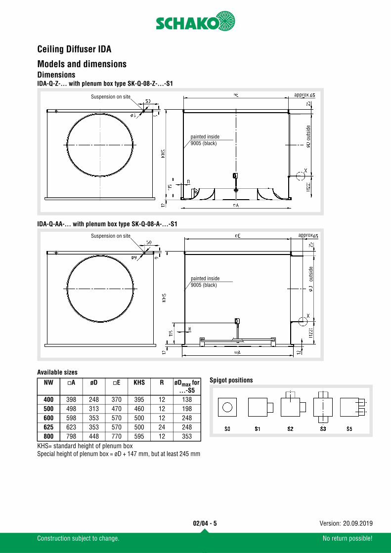
Models and dimensionsDimensionsIDA-Q-Z-... with plenum box type SK-Q-08-Z-...-S1
IDA-Q-AA-... with plenum box type SK-Q-08-A-...-S1
Available sizes
KHS= standard height of plenum boxSpecial height of plenum box = øD + 147 mm, but at least 245 mm
Spigot positions
outs
ide
Suspension on site
painted inside9005 (black)
approx.
outs
ide
Suspension on site
painted inside9005 (black)
approx.
NW A øD E KHS R øDmax for ...-S5
400 398 248 370 395 12 138500 498 313 470 460 12 198600 598 353 570 500 12 248625 623 353 570 500 24 248800 798 448 770 595 12 353
Ceiling Diffuser IDA
02/04 - 6
Construction subject to change. No return possible!
20.09.2019Version:
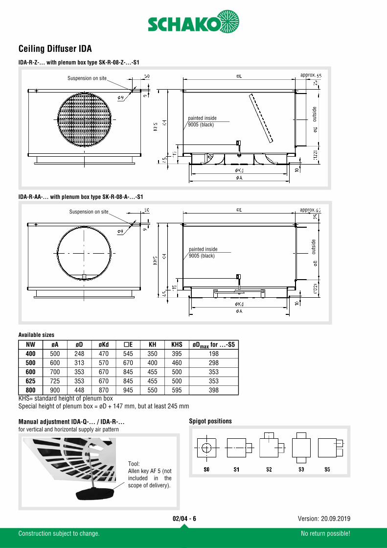
IDA-R-Z-... with plenum box type SK-R-08-Z-...-S1
IDA-R-AA-... with plenum box type SK-R-08-A-...-S1
Available sizes
KHS= standard height of plenum boxSpecial height of plenum box = øD + 147 mm, but at least 245 mm
Manual adjustment IDA-Q-... / IDA-R-...for vertical and horizontal supply air pattern
Spigot positions
outs
ide
Suspension on site
painted inside9005 (black)
approx.
outs
ide
Suspension on site
painted inside9005 (black)
approx.
NW øA øD øKd E KH KHS øDmax for ...-S5400 500 248 470 545 350 395 198500 600 313 570 670 400 460 298600 700 353 670 845 455 500 353625 725 353 670 845 455 500 353800 900 448 870 945 550 595 398
Tool:Allen key AF 5 (notincluded in thescope of delivery).
Ceiling Diffuser IDA
02/04 - 7
Construction subject to change. No return possible!
20.09.2019Version:
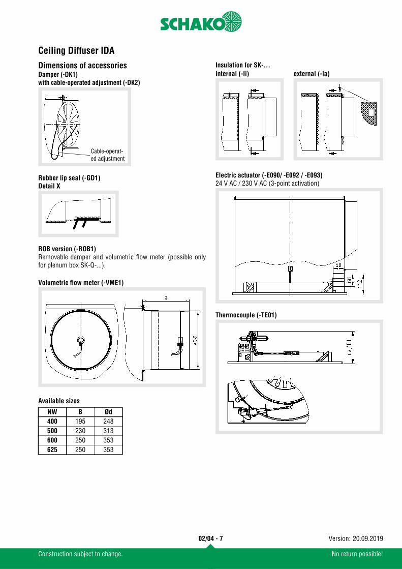
Dimensions of accessoriesDamper (-DK1)with cable-operated adjustment (-DK2)
Rubber lip seal (-GD1)Detail X
ROB version (-ROB1)Removable damper and volumetric flow meter (possible onlyfor plenum box SK-Q-...).
Volumetric flow meter (-VME1)
Available sizes
Insulation for SK-...
Electric actuator (-E090/ -E092 / -E093)24 V AC / 230 V AC (3-point activation)
Thermocouple (-TE01)
NW B Ød400 195 248500 230 313600 250 353625 250 353
Cable-operat-ed adjustment
internal (-Ii) external (-Ia)
Ceiling Diffuser IDA
02/04 - 8
Construction subject to change. No return possible!
20.09.2019Version:
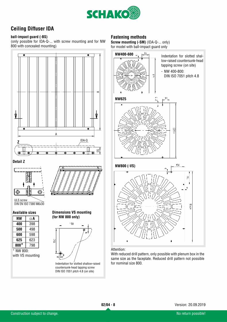
ball-impact guard (-BS)(only possible for IDA-Q-... with screw mounting and for NW800 with concealed mounting)
Fastening methodsScrew mounting (-SM) (IDA-Q-... only)for model with ball-impact guard only
Detail Z
ULS screwDIN EN ISO 7380 M6x30
Available sizes
* NW 800:with VS mounting
NW A400 398500 498600 598625 623
800* 798
IDA-Q
Dimensions VS mounting(for NW 800 only)
Indentation for slotted shallow-raised countersunk-head tapping screwDIN ISO 7051 pitch 4.8 (on site)
NW800 (-VS)
NW400-600
NW625
Indentation for slotted shal-low-raised countersunk-headtapping screw (on site)
- NW 400-800:DIN ISO 7051 pitch 4.8
Attention:With reduced drill pattern, only possible with plenum box in thesame size as the faceplate. Reduced drill pattern not possiblefor nominal size 800.
Ceiling Diffuser IDA
02/04 - 9
Construction subject to change. No return possible!
20.09.2019Version:
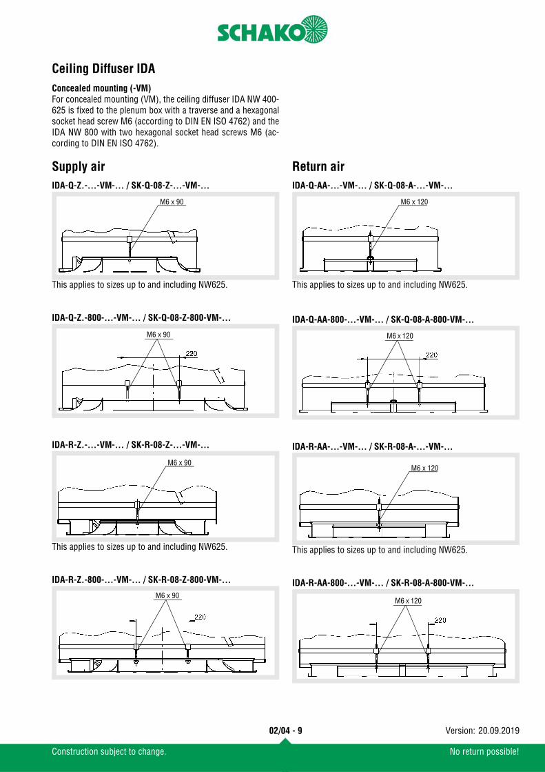
Concealed mounting (-VM)For concealed mounting (VM), the ceiling diffuser IDA NW 400-625 is fixed to the plenum box with a traverse and a hexagonalsocket head screw M6 (according to DIN EN ISO 4762) and theIDA NW 800 with two hexagonal socket head screws M6 (ac-cording to DIN EN ISO 4762).
Supply airIDA-Q-Z.-...-VM-... / SK-Q-08-Z-...-VM-...
This applies to sizes up to and including NW625.
IDA-Q-Z.-800-...-VM-... / SK-Q-08-Z-800-VM-...
IDA-R-Z.-...-VM-... / SK-R-08-Z-...-VM-...
This applies to sizes up to and including NW625.
IDA-R-Z.-800-...-VM-... / SK-R-08-Z-800-VM-...
Return airIDA-Q-AA-...-VM-... / SK-Q-08-A-...-VM-...
This applies to sizes up to and including NW625.
IDA-Q-AA-800-...-VM-... / SK-Q-08-A-800-VM-...
IDA-R-AA-...-VM-... / SK-R-08-A-...-VM-...
This applies to sizes up to and including NW625.
IDA-R-AA-800-...-VM-... / SK-R-08-A-800-VM-...
M6 x 90
M6 x 90
M6 x 90
M6 x 90
M6 x 120
M6 x 120
M6 x 120
M6 x 120

Ceiling Diffuser IDA
02/04 - 10
Construction subject to change. No return possible!
20.09.2019Version:
Technical dataPressure loss and noise levelIDA-...-ZH-400-... (Cooling mode) IDA-...-ZV-400-... (Heating mode)
IDA-...-ZH-500-... (Cooling mode) IDA-...-ZV-500-... (Heating mode)
Damper position:
0% = CLOSED
100% = OPEN
Ceiling Diffuser IDA
02/04 - 11
Construction subject to change. No return possible!
20.09.2019Version:
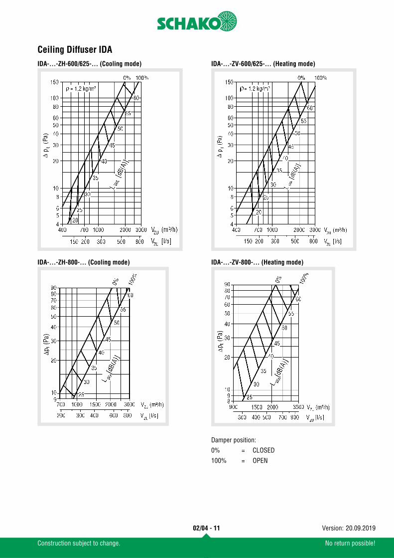
IDA-...-ZH-600/625-... (Cooling mode)
IDA-...-ZH-800-... (Cooling mode)
IDA-...-ZV-600/625-... (Heating mode)
IDA-...-ZV-800-... (Heating mode)
Damper position:
0% = CLOSED
100% = OPEN
Ceiling Diffuser IDA
02/04 - 12
Construction subject to change. No return possible!
20.09.2019Version:
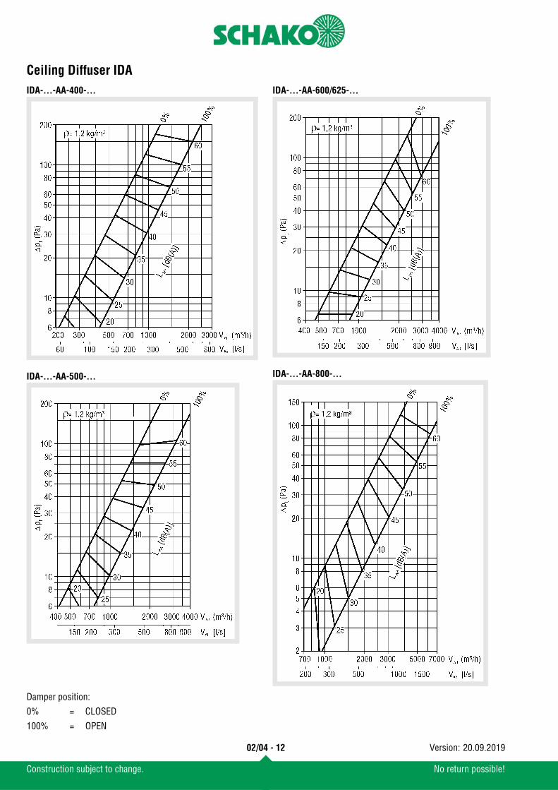
IDA-...-AA-400-...
IDA-...-AA-500-...
IDA-...-AA-600/625-...
IDA-...-AA-800-...
Damper position:
0% = CLOSED
100% = OPEN
Ceiling Diffuser IDA
02/04 - 13
Construction subject to change. No return possible!
20.09.2019Version:
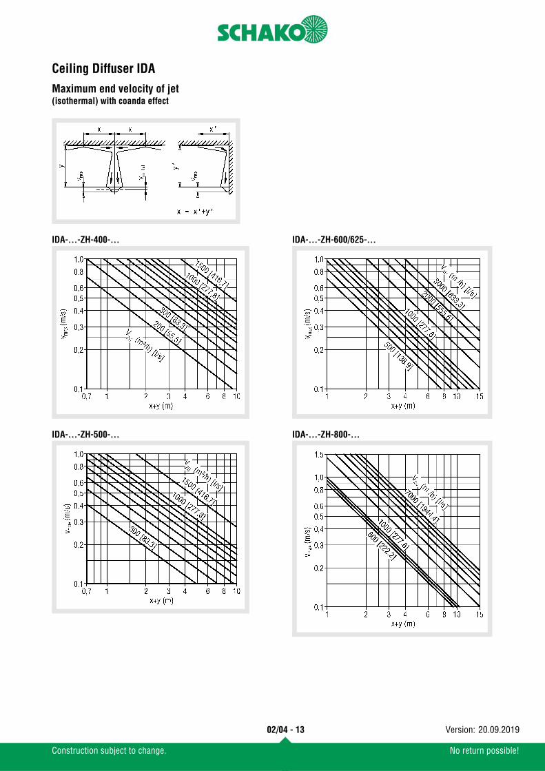
Maximum end velocity of jet(isothermal) with coanda effect
IDA-...-ZH-400-...
IDA-...-ZH-500-...
IDA-...-ZH-600/625-...
IDA-...-ZH-800-...
Ceiling Diffuser IDA
02/04 - 14
Construction subject to change. No return possible!
20.09.2019Version:
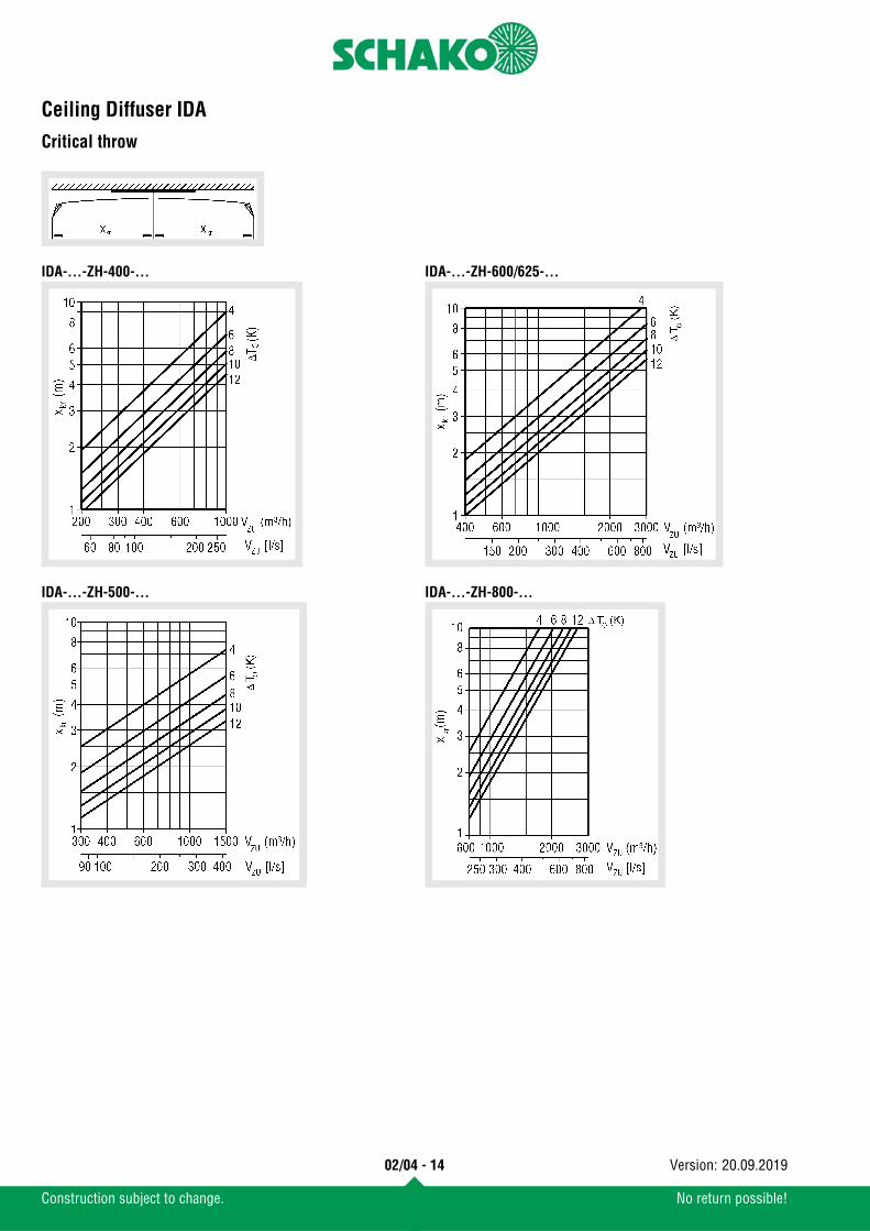
Critical throw
IDA-...-ZH-400-...
IDA-...-ZH-500-...
IDA-...-ZH-600/625-...
IDA-...-ZH-800-...
Ceiling Diffuser IDA
02/04 - 15
Construction subject to change. No return possible!
20.09.2019Version:
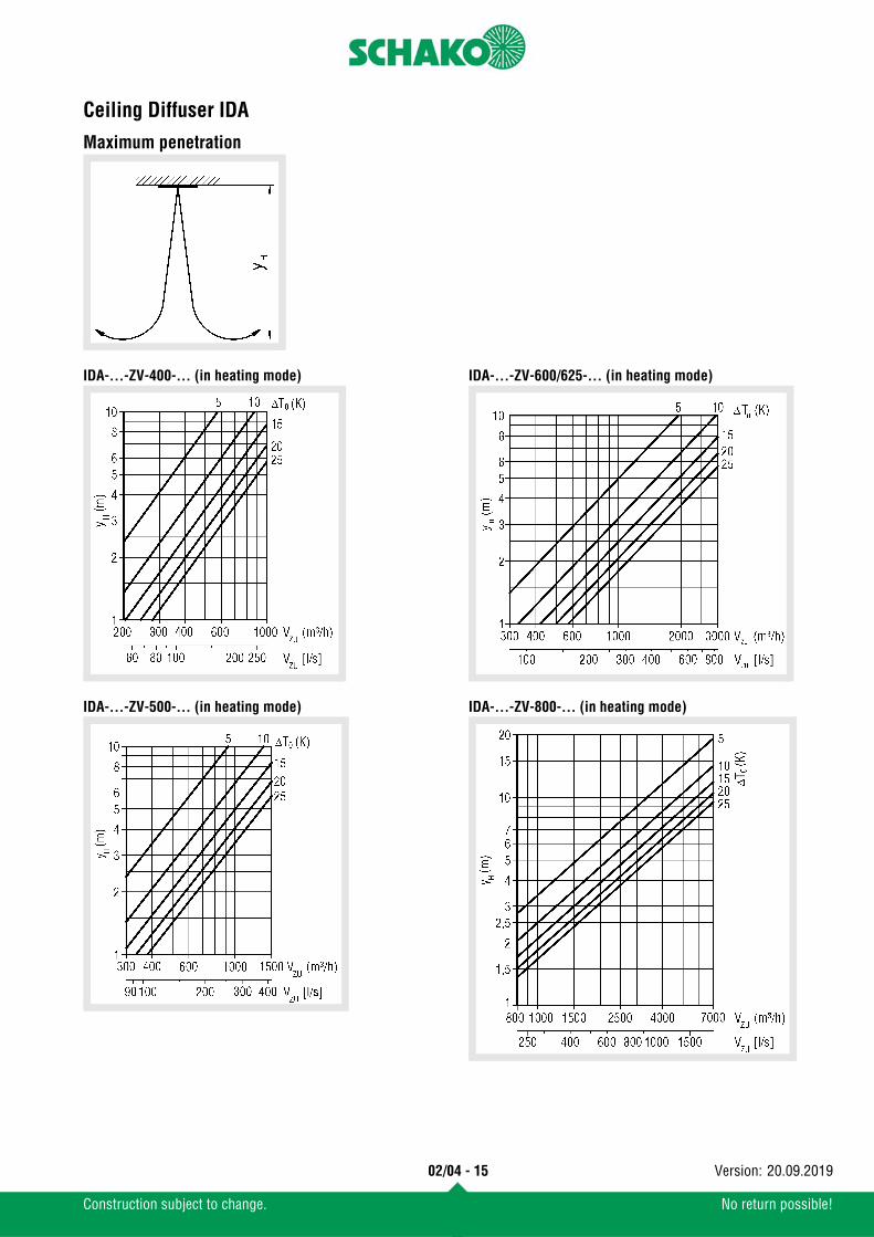
Maximum penetration
IDA-...-ZV-400-... (in heating mode)
IDA-...-ZV-500-... (in heating mode)
IDA-...-ZV-600/625-... (in heating mode)
IDA-...-ZV-800-... (in heating mode)
Ceiling Diffuser IDA
02/04 - 16
Construction subject to change. No return possible!
20.09.2019Version:
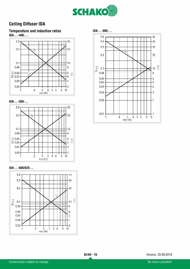
Temperature and induction ratiosIDA-...-400-...
IDA-...-500-...
IDA-...-600/625-...
IDA-...-800-...
Ceiling Diffuser IDA
02/04 - 17
Construction subject to change. No return possible!
20.09.2019Version:
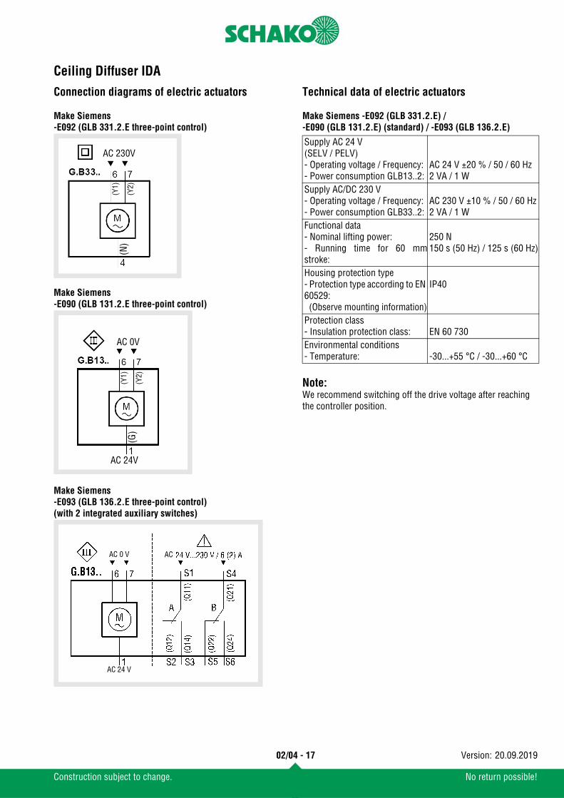
Connection diagrams of electric actuators Make Siemens-E092 (GLB 331.2.E three-point control)
Make Siemens-E090 (GLB 131.2.E three-point control)
Make Siemens-E093 (GLB 136.2.E three-point control)(with 2 integrated auxiliary switches)
Technical data of electric actuators Make Siemens -E092 (GLB 331.2.E) / -E090 (GLB 131.2.E) (standard) / -E093 (GLB 136.2.E)
Note: We recommend switching off the drive voltage after reaching the controller position.
AC 230V
(N)
(Y1)
(Y2)
AC 24V
AC 0V
(G)
(Y1)
(Y2)
ACAC 0 V
AC 24 V
Supply AC 24 V(SELV / PELV)- Operating voltage / Frequency:- Power consumption GLB13..2:
AC 24 V ±20 % / 50 / 60 Hz2 VA / 1 W
Supply AC/DC 230 V- Operating voltage / Frequency:- Power consumption GLB33..2:
AC 230 V ±10 % / 50 / 60 Hz2 VA / 1 W
Functional data- Nominal lifting power:- Running time for 60 mmstroke:
250 N150 s (50 Hz) / 125 s (60 Hz)
Housing protection type- Protection type according to EN 60529: (Observe mounting information)
IP40
Protection class- Insulation protection class: EN 60 730Environmental conditions- Temperature: -30...+55 °C / -30...+60 °C
Ceiling Diffuser IDA
02/04 - 18
Construction subject to change. No return possible!
20.09.2019Version:
LegendVZU (m³/h) [l/s] = Supply air volumeVAB (m³/h) [l/s] = Return air volumeVX (m³/h) [l/s] = Total air jet volume at point xvmax (m/s) = Maximum end velocity of jetvmittel (m/s) = Average end velocity of jet
(vmittel = vmax x 0.5)x (m) = horizontal throwy (m) = vertical throwx+y (m) = Horizontal + vertical throwxkr (m) = Critical throwyH (m) = Maximum penetration in heating modeρ (kg/m³) = DensityΔpt (Pa) = Pressure lossLWA [dB(A)] = A-weighted sound power levelΔTO (K) = Temperature difference between supply
air temperature and room temperature(ΔTO = tZU - tR)
ΔTX (K) = Temperature difference at point xtzu (°C) = Supply air temperaturetR (°C) = Room temperaturei (-) = Induction ratio (i=VX/VZU)TV (-) = Temperature ratio (TV=ΔTX/ΔTO)DS (%) = Damper position
(0% = CLOSED / 100% = OPEN)
Ceiling Diffuser IDA
02/04 - 19
Construction subject to change. No return possible!
20.09.2019Version:
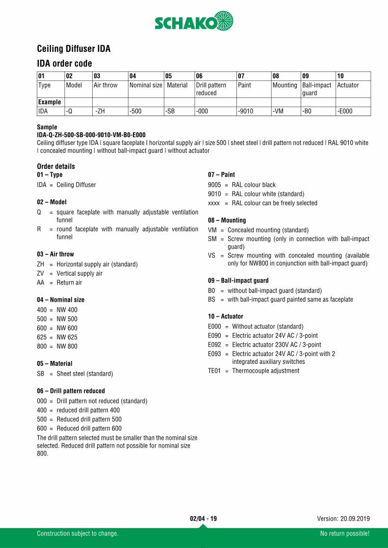
IDA order code
SampleIDA-Q-ZH-500-SB-000-9010-VM-B0-E000Ceiling diffuser type IDA | square faceplate I horizontal supply air | size 500 | sheet steel | drill pattern not reduced | RAL 9010 white | concealed mounting | without ball-impact guard | without actuator
Order details01 – Type
02 – Model
03 – Air throw
04 – Nominal size
05 – Material
06 – Drill pattern reduced
The drill pattern selected must be smaller than the nominal size selected. Reduced drill pattern not possible for nominal size 800.
07 – Paint
08 – Mounting
09 – Ball-impact guard
10 – Actuator
01 02 03 04 05 06 07 08 09 10Type Model Air throw Nominal size Material Drill pattern
reducedPaint Mounting Ball-impact
guardActuator
ExampleIDA -Q -ZH -500 -SB -000 -9010 -VM -B0 -E000
IDA = Ceiling Diffuser
Q = square faceplate with manually adjustable ventilationfunnel
R = round faceplate with manually adjustable ventilationfunnel
ZH = Horizontal supply air (standard)ZV = Vertical supply airAA = Return air
400 = NW 400500 = NW 500600 = NW 600625 = NW 625800 = NW 800
SB = Sheet steel (standard)
000 = Drill pattern not reduced (standard)400 = reduced drill pattern 400500 = Reduced drill pattern 500600 = Reduced drill pattern 600
9005 = RAL colour black9010 = RAL colour white (standard)xxxx = RAL colour can be freely selected
VM = Concealed mounting (standard)SM = Screw mounting (only in connection with ball-impact
guard)VS = Screw mounting with concealed mounting (available
only for NW800 in conjunction with ball-impact guard)
B0 = without ball-impact guard (standard)BS = with ball-impact guard painted same as faceplate
E000 = Without actuator (standard)E090 = Electric actuator 24V AC / 3-pointE092 = Electric actuator 230V AC / 3-pointE093 = Electric actuator 24V AC / 3-point with 2
integrated auxiliary switchesTE01 = Thermocouple adjustment
Ceiling Diffuser IDA
02/04 - 20
Construction subject to change. No return possible!
20.09.2019Version:
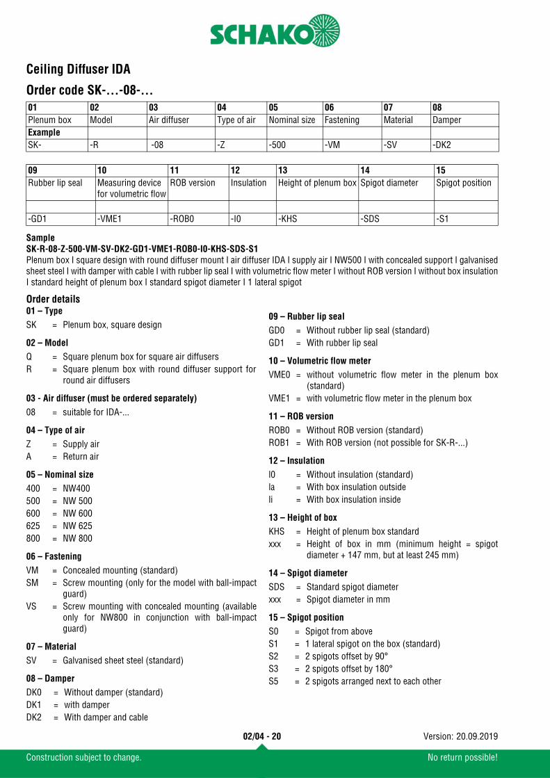
Order code SK-...-08-...
SampleSK-R-08-Z-500-VM-SV-DK2-GD1-VME1-ROB0-I0-KHS-SDS-S1Plenum box I square design with round diffuser mount I air diffuser IDA I supply air I NW500 I with concealed support I galvanisedsheet steel I with damper with cable I with rubber lip seal I with volumetric flow meter I without ROB version I without box insulationI standard height of plenum box I standard spigot diameter I 1 lateral spigot
Order details01 – Type
02 – Model
03 - Air diffuser (must be ordered separately)
04 – Type of air
05 – Nominal size
06 – Fastening
07 – Material
08 – Damper
09 – Rubber lip seal
10 – Volumetric flow meter
11 – ROB version
12 – Insulation
13 – Height of box
14 – Spigot diameter
15 – Spigot position
01 02 03 04 05 06 07 08Plenum box Model Air diffuser Type of air Nominal size Fastening Material DamperExampleSK- -R -08 -Z -500 -VM -SV -DK2
09 10 11 12 13 14 15Rubber lip seal Measuring device
for volumetric flowROB version Insulation Height of plenum box Spigot diameter Spigot position
-GD1 -VME1 -ROB0 -I0 -KHS -SDS -S1
SK = Plenum box, square design
Q = Square plenum box for square air diffusersR = Square plenum box with round diffuser support for
round air diffusers
08 = suitable for IDA-...
Z = Supply airA = Return air
400 = NW400500 = NW 500600 = NW 600625 = NW 625800 = NW 800
VM = Concealed mounting (standard)SM = Screw mounting (only for the model with ball-impact
guard)VS = Screw mounting with concealed mounting (available
only for NW800 in conjunction with ball-impactguard)
SV = Galvanised sheet steel (standard)
DK0 = Without damper (standard)DK1 = with damperDK2 = With damper and cable
GD0 = Without rubber lip seal (standard)GD1 = With rubber lip seal
VME0 = without volumetric flow meter in the plenum box(standard)
VME1 = with volumetric flow meter in the plenum box
ROB0 = Without ROB version (standard)ROB1 = With ROB version (not possible for SK-R-...)
l0 = Without insulation (standard)la = With box insulation outsideli = With box insulation inside
KHS = Height of plenum box standardxxx = Height of box in mm (minimum height = spigot
diameter + 147 mm, but at least 245 mm)
SDS = Standard spigot diameterxxx = Spigot diameter in mm
S0 = Spigot from aboveS1 = 1 lateral spigot on the box (standard)S2 = 2 spigots offset by 90°S3 = 2 spigots offset by 180°S5 = 2 spigots arranged next to each other
Ceiling Diffuser IDA
02/04 - 21
Construction subject to change. No return possible!
20.09.2019Version:
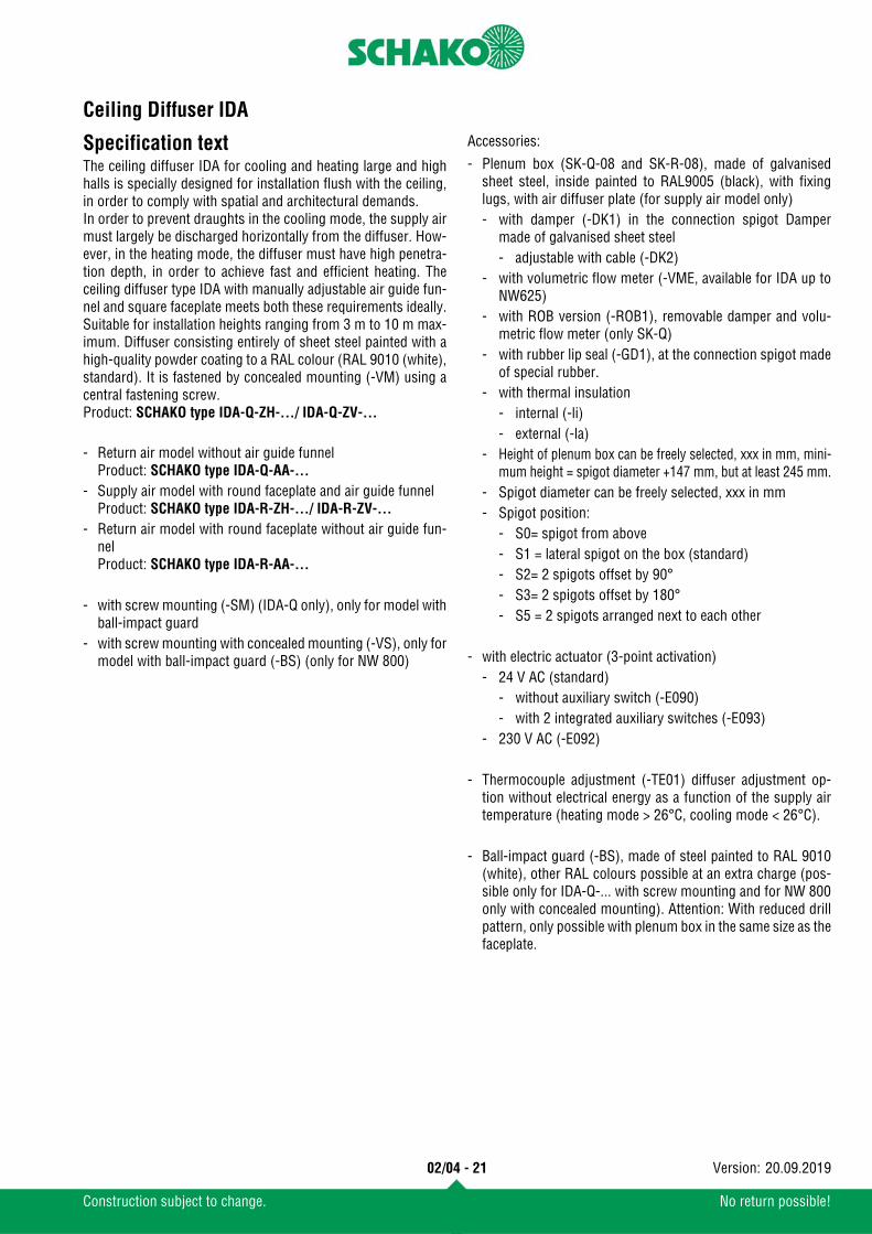
Specification textThe ceiling diffuser IDA for cooling and heating large and highhalls is specially designed for installation flush with the ceiling,in order to comply with spatial and architectural demands. In order to prevent draughts in the cooling mode, the supply airmust largely be discharged horizontally from the diffuser. How-ever, in the heating mode, the diffuser must have high penetra-tion depth, in order to achieve fast and efficient heating. Theceiling diffuser type IDA with manually adjustable air guide fun-nel and square faceplate meets both these requirements ideally.Suitable for installation heights ranging from 3 m to 10 m max-imum. Diffuser consisting entirely of sheet steel painted with ahigh-quality powder coating to a RAL colour (RAL 9010 (white),standard). It is fastened by concealed mounting (-VM) using acentral fastening screw.Product: SCHAKO type IDA-Q-ZH-.../ IDA-Q-ZV-...
Accessories:
- Return air model without air guide funnelProduct: SCHAKO type IDA-Q-AA-...
- Supply air model with round faceplate and air guide funnelProduct: SCHAKO type IDA-R-ZH-.../ IDA-R-ZV-...
- Return air model with round faceplate without air guide fun-nelProduct: SCHAKO type IDA-R-AA-...
- with screw mounting (-SM) (IDA-Q only), only for model withball-impact guard
- with screw mounting with concealed mounting (-VS), only formodel with ball-impact guard (-BS) (only for NW 800)
- Plenum box (SK-Q-08 and SK-R-08), made of galvanisedsheet steel, inside painted to RAL9005 (black), with fixinglugs, with air diffuser plate (for supply air model only)- with damper (-DK1) in the connection spigot Damper
made of galvanised sheet steel- adjustable with cable (-DK2)
- with volumetric flow meter (-VME, available for IDA up toNW625)
- with ROB version (-ROB1), removable damper and volu-metric flow meter (only SK-Q)
- with rubber lip seal (-GD1), at the connection spigot madeof special rubber.
- with thermal insulation- internal (-li)- external (-la)
- Height of plenum box can be freely selected, xxx in mm, mini-mum height = spigot diameter +147 mm, but at least 245 mm.
- Spigot diameter can be freely selected, xxx in mm- Spigot position:
- S0= spigot from above- S1 = lateral spigot on the box (standard)- S2= 2 spigots offset by 90°- S3= 2 spigots offset by 180°- S5 = 2 spigots arranged next to each other
- with electric actuator (3-point activation)- 24 V AC (standard)
- without auxiliary switch (-E090)- with 2 integrated auxiliary switches (-E093)
- 230 V AC (-E092)
- Thermocouple adjustment (-TE01) diffuser adjustment op-tion without electrical energy as a function of the supply airtemperature (heating mode > 26°C, cooling mode < 26°C).
- Ball-impact guard (-BS), made of steel painted to RAL 9010(white), other RAL colours possible at an extra charge (pos-sible only for IDA-Q-... with screw mounting and for NW 800only with concealed mounting). Attention: With reduced drillpattern, only possible with plenum box in the same size as thefaceplate.