celotex handy guide
DESCRIPTION
Celotex Handy GuideTRANSCRIPT

The CelotexHandyGuide Your
essential guide toreducing carbonemissions using
Celotex


04 ▶ Future proofing energy performance
06 ▶ Celotex – we know insulation inside and out
08 ▶ Product descriptions
14 ▶ Celotex accessories
16 ▶ Insulation solutions using plasterboard thermal laminate
18 Insulation between and under rafters using PL3000
20 Insulation between and under joists using PL3000
22 Internal insulation solutions using PL3000
24 Single timber frame wall lining and dormer cheeks using PL3000
26 ▶ Insulation solutions for pitched roofs
28 Pitched roof sarking
30 Insulation between and over rafters
32 Insulation between rafters
34 Insulation between and under rafters
36 ▶ Insulation solutions for flat roofs
38 Built-up flat roofing applications
40 Flat roof insulating deck
42 Insulation between joists
44 Insulation between and under joists
46 ▶ Insulation solutions for walls
48 Masonry cavity walls
50 Blockwork comparison list
52 Solid masonry walls (internal)
54 Solid masonry walls (external)
56 Timber frame wall lining
58 Single timber frame wall lining and dormer cheeks
60 Timber frame wall sheathing
62 Steel stud framed walls
64 Rainscreen cladding
66 ▶ Insulation solutions for floors
68 Calculating the P/A ratio
70 Concrete slab floors
72 Beam and block floors
74 Suspended timber floors
76 Underfloor heating
78 Concrete soffit floors
80 ▶ Garage conversions
82 ▶ Loft conversions
84 ▶ Environmental & sustainability statement
86 ▶ Notes
Contents
03

Future proofing energy performance
04
In November 2008, the UK agreed to reduce itsCO2 emissions by 80% by 2050 as part of theClimate Change Act. This represents the world’sfirst legally binding agreement for the reductionof CO2; one of the main greenhouse gasesresponsible for global warming and climatechange.
The pursuit of carbon reduction in UK homesand buildings continues to drive theconstruction industry on a day to day basis. UKhomes and buildings, as well as the manufactureof the materials used to build them, account forover 50% of the UK’s total CO2 emissions.
Approved Document L of the BuildingRegulations for England & Wales, Section 6 of theScottish Technical Handbook and TechnicalBooklet F for Northern Ireland determine theminimum building standards required forenergy performance. As an extension of this,BREEAM schemes, such as the Code forSustainable Homes, provide increased levels ofbuilding regulation where sustainable building isat the forefront of design and build. ApprovedDocument L will be republished in 2010 withfurther improvements required for energy
performance. These legislative frameworks assistin the improvement of a building’s energyperformance, helping to prevent heat loss andmaximise thermal performance, as well aspromoting the use of materials with a lowenvironmental impact.
Through its low thermal conductivity, Celotex PIRinsulation boards enable maximum thermalperformance within a building’s fabric, achievedwith the minimum level of thickness. With arange of products suitable for floors, walls,pitched and flat roofs, as well as its premiumthermal range, FR4000, Celotex is proven to helpdeliver even lower U-values and help futureproof the energy performance of a building.
Coupled with industry-leading sustainabilitycredentials including an A+ rating in the 2008Green Guide and the lowest environmentalimpact of any PIR manufacturer, the selectionand performance of Celotex products will ensurefuture building stock will have fewer negativeimpacts on the environment.
For full details of Celotex’ sustainability position,please refer to pages 84 and 85.
Using Celotex to meet sustainability legislation
T: 0901 996 0100*
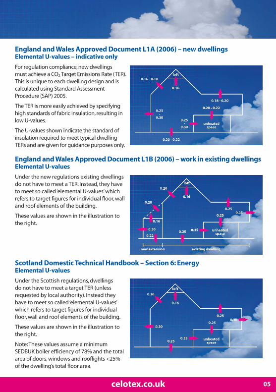
England and Wales Approved Document L1A (2006) – new dwellingsElemental U-values – indicative only
For regulation compliance, new dwellings must achieve a CO2 Target Emissions Rate (TER).This is unique to each dwelling design and iscalculated using Standard AssessmentProcedure (SAP) 2005.
The TER is more easily achieved by specifyinghigh standards of fabric insulation, resulting inlow U-values.
The U-values shown indicate the standard ofinsulation required to meet typical dwellingTERs and are given for guidance purposes only.
England and Wales Approved Document L1B (2006) – work in existing dwellingsElemental U-values
Under the new regulations existing dwellingsdo not have to meet a TER. Instead, they haveto meet so called ‘elemental U-values’ whichrefers to target figures for individual floor, walland roof elements of the building.
These values are shown in the illustration tothe right.
Scotland Domestic Technical Handbook – Section 6: EnergyElemental U-values
Under the Scottish regulations, dwellings do not have to meet a target TER (unlessrequested by local authority). Instead theyhave to meet so called ‘elemental U-values’which refers to target figures for individualfloor, wall and roof elements of the building.
These values are shown in the illustration tothe right.
Note: These values assume a minimumSEDBUK boiler efficiency of 78% and the totalarea of doors, windows and rooflights <25% of the dwelling’s total floor area.
05celotex.co.uk

Celotex – we know insulation inside and out
Throughout its eighty years of operation, Celotexhas continually provided innovative andbreakthrough solutions to supply thermallyefficient insulation products to the market.
As the UK’s pioneers of PIR insulation, Celotex -with its policy of continual product developmentand innovation – continues to pave the wayforwards; developing new product solutions tomeet the current and future targets of zerocarbon regulations and fulfilling therequirements of building professionals, specifiersand users.
The pursuit of zero carbon and meeting thedemands of the Climate Change Act areconstantly driving forwards our product andservice developments, ensuring we maintain ourposition as the UK’s brand leading provider of PIRthermal insulation solutions.
Why Celotex PIR insulation?
An expansive product range combined with thebroadest range of product thicknesses, anindustry-leading technical centre and anunrivalled sustainability position allow us tomaintain a considerable advantage over ourcompetitors. This is best reflected through our in-depth knowledge of manufacturing techniquesand corresponding achievements in productperformance.
Celotex PIR insulation offers the followingbenefits:
▶ low thermal conductivity minimising heat loss
▶ Better thermal efficiency per mm than otherinsulation materials, allowing for thinnersolutions
▶ A range of products suitable for floors, walls,pitched and flat roofs, with the broadest range ofproduct thicknesses, available from 12mm to200mm
▶ Low emissivity aluminium foil facings furtherimproving thermal efficiency in application
▶ Unrivalled sustainability credentials includingan A+ rating in the 2008 Green Guide
▶ Industry leading technical support via theCelotex Technical Centre and online atcelotex.co.uk
Range overview
Celotex offers the widest range of thicknessesamongst all PIR insulation providers, withproducts available from 12mm through to200mm. This unrivalled product offering providesthermal insulation solutions for variety ofapplications.
Our improved FR4000 has been achievedthrough ongoing product innovation andtechnological breakthrough. The productcombines premium thermal performance with aGreen Guide rating of A, as well as low GWP andClass O fire performance throughout the entireproduct. FR4000 is available from 25mm-200mmthick and is suitable for use in pitched roofs, wallsand floors. With a smaller board, CG4000, alsoavailable for partial fill cavity walls, these productswill offer you a higher level of insulationperformance compared with typical PIR.
Our TB3000, GA3000 and XR3000 ranges providemulti-purpose solutions for use within floor, walland roof applications. Our thinner productsprovide the solution for overcoming localisedthermal bridging whereas our thicker XR3000range helps achieve even better U-values thanpreviously possible with a single-layer system.
PL3000 – our plasterboard thermal laminate – isthe ideal product for insulating dry-liningapplications and, along with our plywoodlaminate TD3000, is now exclusivelymanufactured on our state of the art laminationfacility allowing for greater product choice.
For flat roofing solutions, Celotex EL3000 andTA3000 provide maximum versatility and comefully supported with industry approvals fromleading third parties.
06 T: 0901 996 0100*

We also have specialist product solutions forpartial fill cavity walls (CW3000) and underfloorheating (FF3000).
For further details of Celotex products, pleaserefer to the Product Descriptions overleaf ordownload comprehensive product datasheetsfrom our website at celotex.co.uk.
Celotex Technical Centre
Staffed by experienced construction specialists,the Celotex Technical Centre has earned anexcellent reputation for its comprehensive levelsof personal assistance and technical support.
In line with Part L of the Building Regulations, weoffer a service to calculate SAP ratings fordwellings as well being able to provide EnergyPerformance Certificates via our own in-houseOn Construction Energy Assessors.
U-value calculations for all product applicationsare also available, along with advice on anyaspect of meeting relevant building legislation.
The Celotex Technical Centre is open from 8am to5.15pm to provide the maximum levels ofcoverage to the building professional andspecifier. For further information or to contact theteam, visit celotex.co.uk or call 0901 996 0100*.
celotex.co.uk
For the latest news and information regardingCelotex products and services, please visit ourwebsite at celotex.co.uk.
Whether for product information and applicationguidelines, or to purchase SAP calculations andEnergy Performance Certificates, you will findeverything you need from the insulationspecialists.
The site also includes the popular Celotex U-value calculator for instant U-value calculations aswell as technical literature and downloadsincluding all you need to know aboutsustainability and the road to zero carbon, alongwith copies of Celotex BBA certificates.
Sustainability
Celotex products have been independentlyassessed by BRE Global and have been confirmedas achieving the lowest environmental impactamongst all PIR manufacturers. This profilingdrives our A+ rating within the 2008 Green Guideallowing credits to be earned under the relevantsections of The Code for Sustainable Homes andBREEAM schemes. As Celotex products are alsolow GWP and zero ODP rated further credits canalso be gained in other relevant categories.
Through our unique A+ Green Guide rating,lowest environmental impact rating and depth ofproduct offering, Celotex is proven to be themost sustainable PIR product solution.
For full details of our sustainability andenvironmental credentials please refer to pages84 and 85 or visit celotex.co.uk to download oursustainability guide – Sustainability and The Roadto Zero Carbon.
07celotex.co.uk

Product descriptions
08 T: 0901 996 0100*
Celotex FR4000 is our premium performancePIR solution. Through ongoing product innovationand breakthrough design techniques, FR4000offers enhanced thermal performance as well asan ‘A’ rating in the 2008 Green Guide, has low GWPand Class O fire performance throughout theentire product.
FR4000 is targeted specifically at pitched roof, wall,floor and soffit applications and is available in thebroadest range of thicknesses, from 25mm-200mm. This latest product offering from Celotexdelivers superior insulation performancecompared with traditional PIR products.
Always install Celotex FR4000 in accordance withthe instructions supplied by Celotex Limited.
Standard board dimensions1200mm x 2400mm
Physical propertiesThermal resistance (R) values for Celotexproducts are declared in accordance with BS EN13165. These R-values equate to a ThermalConductivity (λ) value of 0.022W/mK.
Fire resistanceIn accordance with the results of BS 476 Parts 6 &7, FR4000 complies with the requirements ofClass O as defined in the Building Regulations.
Celotex CG4000 is our premium performancePIR solution specifically designed for partial fillcavity wall applications. As well as enhancedthermal performance, CG4000 offers an ‘A’ ratingin the 2008 Green Guide, has low GWP and ClassO fire performance throughout the entireproduct.
CG4000 is available in a range of thicknessesfrom 40mm-100mm and delivers superiorinsulation performance compared withtraditional PIR products.
Always install Celotex CG4000 in accordancewith the instructions supplied by CelotexLimited.
Standard board dimensions
1200mm x 450mm
Physical properties
Thermal resistance (R) values for Celotexproducts are declared in accordance with BS EN13165. These R-values equate to a ThermalConductivity (λ) value of 0.022W/mK.
Fire resistance
In accordance with the results of BS 476 Parts 6 &7, CG4000 complies with the requirements ofClass O as defined in the Building Regulations.
FR4025 25 1.10FR4030 30 1.35FR4035 35 1.55FR4040 40 1.80FR4045 45 2.00FR4050 50 2.25FR4060 60 2.70FR4070 70 3.15FR4075 75 3.40FR4080 80 3.60FR4090 90 4.05FR4100 100 4.50FR4110 110 5.00FR4120 120 5.45FR4130 130 5.90FR4140 140 6.35FR4150 150 6.80FR4165 165 7.50FR4200 200 9.05
Product rangeProduct code Thickness (mm) R-value (m2K/W)
CG4040 40 1.80CG4045 45 2.00CG4050 50 2.25CG4060 60 2.70CG4070 70 3.15CG4075 75 3.40CG4080 80 3.60CG4090 90 4.05CG4100 100 4.50
Product rangeProduct code Thickness (mm) R-value (m2K/W)

09celotex.co.uk
Celotex TB3000 is a thin, foil faced insulationboard with thicknesses ranging from 12mm -45mm. Celotex TB3000 is designed to providesimple solutions to overcome localised thermalbridges. Celotex is unique in being able to offerboards as thin as 12mm to the market for thispurpose.
Always install Celotex TB3000 in accordance withthe instructions supplied by Celotex Limited.
Standard board dimensions
1200mm x 2400mm (with grid markings to assistinstallation).
Physical properties
Thermal resistance (R) values for Celotexproducts are declared in accordance with BS EN13165. These R-values equate to a ThermalConductivity (λ) value of 0.023 W/mK.
Fire resistance
Reaction to fire = Euroclass F in accordance withBS EN 13501.Surface spread of flame in accordance with BS 476 Part 7 = Class 1.
Celotex GA3000 has long been at the heart ofthe Celotex product range, providing a range ofthermal insulation solutions to the builder. TheCelotex GA3000 product is a foil faced thermalinsulation board featuring the best reaction-to-fire performance (Euroclass D/s2/d0) whenmeasured in accordance with new EuropeanStandards compared with similar products onthe market.
Always install Celotex GA3000 in accordancewith the instructions supplied by CelotexLimited.
Standard board dimensions
1200mm x 2400mm (with grid markings to assistinstallation).
Physical properties
Thermal resistance (R) values for Celotexproducts are declared in accordance with BS EN13165. These R-values equate to a ThermalConductivity (λ) value of 0.023 W/mK.
Fire resistance
Reaction to fire in accordance with BS EN 13501= Euroclass D (except 50mm & 100mm =Euroclass F). Surface spread of flame in accordance with BS 476 Part 7 = Class 1 (50 - 90mm only).
GA3050 50 2.15GA3055 55 2.35GA3060 60 2.60GA3065 65 2.80GA3070 70 3.00GA3075 75 3.25GA3080 80 3.45GA3090 90 3.90GA3100 100 4.30
Product rangeProduct code Thickness (mm) R-value (m2K/W)
TB3012 12 0.50TB3020 20 0.85TB3025 25 1.05TB3030 30 1.30TB3035 35 1.50TB3040 40 1.70TB3045 45 1.95
Product rangeProduct code Thickness (mm) R-value (m2K/W)

Product descriptions
10 T: 0901 996 0100*
Celotex XR3000 is manufactured on our state-of-the-art restrained rise production linefeaturing our own unique jointless lay downtechnology. This technology enables us to offerthicker boards with no visible seams in the PIRfoam core. This foil faced product is targeted at‘cut-to-fit’ applications for insulation betweenrafters or joists and will enable users to achievelower U-values with a single layer of insulationthan has previously been possible and will helpdesigners meet the present and futurerequirements of Approved Document L (2006) of the Building Regulations, BREEAM and theCode for Sustainable Homes.
Always install Celotex XR3000 in accordancewith the instructions supplied by CelotexLimited.
Standard board dimensions
1200mm x 2400mm (with grid markings to assistinstallation).
Physical properties
Thermal resistance (R) values for Celotexproducts are declared in accordance with BS EN 13165. These R-values equate to a Thermal Conductivity (λ) value of 0.023 W/mK.
Fire resistance
Reaction to fire = Euroclass F in accordance withBS EN 13501.
Celotex CW3000 provides a simple cavity wallinsulation solution with a foil faced thermalinsulation board. These products feature a goodreaction-to-fire performance (Euroclass D/s2/d0)measured in accordance with new EuropeanStandards compared to any similar product onthe market.
Always install Celotex CW3000 in accordancewith the instructions supplied by CelotexLimited.
Standard board dimensions
1200mm x 450mm (with grid markings to assistinstallation).
Physical properties
Thermal resistance (R) values for Celotexproducts are declared in accordance with BS EN13165. These R-values equate to a ThermalConductivity (λ) value of 0.023 W/mK.
Fire resistance
Reaction to fire in accordance with BS EN 13501 =Euroclass D (except 25 - 50mm and 100mm =Euroclass F).
Surface spread of flame in accordance with BS 476Part 7 = Class 1 (25 - 90mm only).
XR3110 110 4.75XR3120 120 5.20XR3130 130 5.65XR3140 140 6.05XR3150 150 6.50XR3165 165 7.15XR3200 200 8.65
Product rangeProduct code Thickness (mm) R-value (m2K/W)
CW3025 25 1.05CW3030 30 1.30CW3035 35 1.50CW3040 40 1.70CW3045 45 1.95CW3050 50 2.15CW3055 55 2.35CW3060 60 2.60CW3065 65 2.80CW3070 70 3.00CW3075 75 3.25CW3080 80 3.45CW3090 90 3.90CW3100 100 4.30
Product rangeProduct code Thickness (mm) R-value (m2K/W)

11celotex.co.uk
Celotex PL3000 is a high performance thermalinsulation board where the PIR insulation isbonded to a 12.5mm sheet of tapered edgeplasterboard.
Celotex PL3000 is suitable for both directbonding and mechanically fixed applications andallows the user to install both the insulation andplasterboard in one operation thereby reducinginstallation times.
Celotex PL3000 is suitable as the underneathlayer of insulation in both pitched and flat roof‘between and under’ applications as well as ininternal dry lining applications. It can be used innew build applications as well as providing theperfect solution for upgrading older buildingswhere little or no insulation exists.
Always install the Celotex PL3000 in accordancewith the instructions supplied by Celotex Limited.
Standard board dimensions
1200mm x 2400mm (with grid markings to assistinstallation).
Physical properties
Thermal resistance (R) values for Celotex productsare declared in accordance with BS EN 13165.These R-values equate to a Thermal Conductivity(λ) value of 0.023W/mK (insulation only)
Fire resistance (insulation only)
Reaction to fire in accordance with BS EN 13501 = Euroclass F.
The plasterboard used in PL3000 is defined asClass O in accordance with the BuildingRegulations.
Celotex FF3000 is manufactured on our state-of-the-art restrained rise production linefeaturing our own unique jointless lay downtechnology. This technology enables us to offerthicker boards with no visible seams in the foamcore. This foil faced product is targetedspecifically at ‘under screed’ floor applications -including underfloor heating systems - where thehigher density and compressive strength bothprove valuable to the installer.
Always install Celotex FF3000 in accordance withthe instructions supplied by Celotex Limited.
Standard board dimensions
1200mm x 2400mm (with grid markings to assistinstallation).
Physical properties
Thermal resistance (R) values for Celotex productsare declared in accordance with BS EN 13165.These R-values equate to a Thermal Conductivity(λ) value of 0.023 W/mK.
Fire resistance
Reaction to fire = Euroclass F in accordance withBS EN 13501.
PL3025 25 + 12.5 1.15PL3040 40 + 12.5 1.80PL3055 55 + 12.5 2.45PL3065 65 + 12.5 2.90
Product rangeCombined
Product code Thickness (mm) R-value (m2K/W)
FF3050L 50 2.15FF3070L 70 3.00FF3075L 75 3.25FF3085L 85 3.65FF3090L 90 3.90FF3100L 100 4.30FF3125L 125 5.40FF3150L 150 6.50
Product rangeProduct code Thickness (mm) R-value (m2K/W)

Product descriptions
12 T: 0901 996 0100*
Product rangeProduct code Thickness (mm) Combined
insulation + ply R-value (m2K/W)
EL3050 50 1.85EL3080 80 3.05EL3090 90 3.45EL3100 100 3.80EL3110 110 4.20EL3120 120 4.80EL3140 140 5.60EL3150 150 6.00EL3165 165 6.60EL3200 200 8.00
Product rangeProduct code Thickness (mm) R-value (m2K/W)
Celotex TD3000 provides a quick and easy wayto achieve effective thermally insulated roofdecks for building structures such as smallextensions or garage roofs where there will beonly occasional trafficking. These productsfeature a foil faced insulation board, to give thebest insulation value possible, bonded to a facingof 5.5mm WBP ply. This allows the user to installthe roof structure in one operation since theproduct provides the deck, insulation and vapourcontrol layer thereby considerably reducinginstallation times ahead of weatherproofing.
Always install Celotex TD3000 in accordance withthe instructions supplied by Celotex Limited.
Standard board dimensions
1200mm x 2400mm (with grid markings to assistinstallation).
Physical properties
Thermal resistance (R) values for Celotexproducts are declared in accordance with BS EN13165. These R-values equate to a ThermalConductivity (λ) value of 0.023 W/mK (insulationonly).
Fire resistance (insulation only)
Reaction to fire in accordance with BS EN 13501 =Euroclass D (except TD3106 - TD3156 = Euroclass F).
Surface spread of flame in accordance with BS 476Part 7 = Class 1 (TD3076 - TD3096 only).
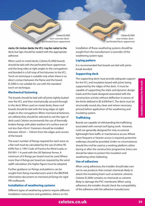
Celotex EL3000 is a purpose-designed insulationboard for use in built-up flat roofing applications,including hot-applied bituminous and masticasphalt waterproofing systems and fully adheredsingle-ply membranes.
Celotex EL3000 features a coated glass tissue facer,perforated on one side for use in bitumen-basedbuilt-up applications, whilst the reverseunperforated facer is suitable for single-plymembrane applications. Celotex EL3000 is availablein two different lengths and in a range ofthicknesses allowing you to achieve U-values withminimum thickness.
Always install Celotex EL3000 in accordance withthe instructions supplied by Celotex Limited.
Standard board dimensions
1200mm x 600mm and 1200mm x 2400mm(EL3050, EL3080 and EL3110 available in 600mmlength only).
Physical properties
Thermal resistance (R) values for Celotex productsare declared in accordance with BS EN 13165. TheseR-values equate to a Thermal Conductivity (λ) valueof:
0.027W/mK for product thickness under 80mm0.026W/mK for product thickness between 80-119mm0.025W/mK for product thickness of 120mm or over.
Fire resistance
External roof exposure = Ext. FAB in accordance withBS 476-3. Reaction to fire = Euroclass F in accordance with BS EN 13501.
TD3076 70 + 5.5 3.05TD3081 75 + 5.5 3.30TD3086 80 + 5.5 3.50TD3096 90 + 5.5 3.95TD3106 100 + 5.5 4.35TD3116 110 + 5.5 4.80TD3126 120 + 5.5 5.25TD3136 130 + 5.5 5.65TD3146 140 + 5.5 6.10TD3156 150 + 5.5 6.55
Product rangeProduct code Thickness (mm) Combined
insulation + ply R-value (m2K/W)

Celotex TA3000 is a purpose designedinsulation board for use with mechanically fixedand ballasted single-ply weathering systems. Itprovides a quick and easy way to achieve effectivethermal insulation in flat roofing structures. Theseboards all feature the unique jointless lay downsystem to improve the flatness of the product.
Celotex TA3000 performs to a compressivestrength of 150kPa giving improved resistance tosite traffic during installation and is available inthicknesses ranging from 50mm – 200mm.
Always install Celotex TA3000 in accordance withthe instructions supplied by Celotex Limited.
Standard board dimensions
1200mm x 2400mm (with grid markings to assistinstallation).
Physical properties
Thermal resistance (R) values for Celotex productsare declared in accordance with BS EN 13165.These R-values equate to a Thermal Conductivity(λ) value of 0.023 W/mK.
Fire resistance
Reaction to fire in accordance with BS EN 13501 =Euroclass F.
Celotex LG3000 is a high performanceinsulation board for use in commercial,agricultural and industrial buildings. It is offeredwith a grey painted stucco embossed foil faceand approval from the Loss PreventionCertification Board (LPCB).
Celotex LG3000 achieves a class leading reaction-to-fire performance of Euroclass B/s2/d0 whenmeasured in accordance with EuropeanStandards. As well as excellent dimensionalstability, LG3000 is lightweight, rapidly installedand provides a semi-decorative finish.
Always install Celotex LG3000 in accordance withthe instructions supplied by Celotex Limited.
Standard board dimensions
1200mm x 2400mm
Physical properties
Thermal resistance (R) values for Celotex productsare declared in accordance with BS EN 13165.These R-values equate to a Thermal Conductivity(λ) value of 0.022 W/mK.
Fire resistance
Reaction to fire in accordance with BS EN 13501 = Class B/s2/d0. Surface spread of flame in accordance with BS 476 Part 6 & 7 = Class 1.
13celotex.co.uk
LG3025 25 1.10LG3030 30 1.35LG3040 40 1.80LG3050 50 2.25
Product rangeProduct code Thickness (mm) R-value (m2K/W)
TA3050 50 2.15TA3070 70 3.00TA3075 75 3.25TA3085 85 3.65TA3090 90 3.90TA3100 100 4.30TA3110 110 4.75TA3125 125 5.40TA3150 150 6.50TA3165 165 7.15TA3200 200 8.65
Product rangeProduct code Thickness (mm) R-value (m2K/W)

Celotex accessories
14 T: 0901 996 0100*
Celotex Insulation Tape
For the sealing of joints when installing foil-facedCelotex PIR insulation boards. This 3 in 1 productprevents air leakage, completes the vapourcontrol layer and maximises thermal performance.Celotex Insulation Tape is suitable for a range ofapplications, including walling systems andpitched and flat roofing applications.
Roll size
48mm x 55metres
Celotex Insulation SawWhen cutting Celotex PIR insulation boards, usethe Celotex Insulation Saw. The saw is the only oneon the market specifically for cutting PIRinsulation boards. Featuring fine, hard point teeth,it is proven to dramatically reduce the amount ofdust created when cutting Celotex insulationboards as well as reducing cutting time.
Physical propertiesSaw length: 350mmSaw weight: 225gramsTooth Protector Clip included
Celotex HoodsThe Celotex Hoods are a branded polytheneweatherproofing hood, which allow for theexternal storage and protection of Celotexproducts. The Hoods remove the need forunsuitable covering methods such as tarpaulinsand rope which can damage the boards. They arealso easy to use and are suitable for repeat use; anideal storage solution when inside space is limited.
Physical propertiesCovers Celotex pack size of 1200mm (D) x2400mm (W) x 1250mm (H).
Supplied on a roll, 25 hoods per roll, perforated for easy use.
For further information about these accessoryproducts or for a list of suppliers of ancillarycomponents for floor, wall and roof applications,visit celotex.co.uk or contact our SalesDepartment.

Celotex Insulation Clip
15celotex.co.uk
Introduction
The Celotex Insulation Clip has been designed toenable insulation boards to be installed betweentimber joists or rafters quickly and without the needfor nails, screws or battens. They provide a permanentway of securing the Celotex insulation with as littlefuss as possible.
The clip should be used in situations where theinsulation is being installed from above or below, forexample when fitting between joists in a suspendedtimber floor.
Using the clip ensures that the insulation will be heldfirmly in place once installed in the correct manner.
Installation guidelines
▶ The joists / rafters should be installed in the conventionalmanner in accordance with the Building Regulations.
▶ Cut the Celotex insulation boards to the width of the spacebetween the joists / rafters ensuring a straight edge to theboard to enable a tight interference fit.
▶ Push the insulation clips into the board at 1000mmintervals with the two prongs piercing the exposed foamdown the long edge of the board (see fig.1).
▶ Start the clips in between the joists / rafters and push theboard into place (see fig.2). This should be a tight fit tominimise heat loss through the gaps between the joist /rafter and insulation board.
▶ Push the board fully home so that the base of theinsulation clip is level with the face of the joist / rafter (see fig.3).
▶ If additional board security is required, for example wherethere is no lining below the joists / rafters, nail through thebase of the clip directly into the joist (see fig.4).
▶ Where additional insulation or plasterboard is requiredbelow the joists / rafters, continue as in the Celotex literaturefor that application (see fig.5).
Fig. 2
Fig. 3
Fig. 4
Fig. 5
Fig. 1

Pitched roof insulation betweenand under raftersIf sarking felt is being used, a minimum 50mmventilation air space must be provided betweenthe felt and cold side of the insulation in order tominimise the risk of condensation formation. Thisis known as ventilated construction.
If a breathable membrane is being used, allowthe membrane to sag between the rafterscreating an unventilated air gap ofapproximately 20mm between the membraneand the cold side of the insulation. However,when fixing counter battens for drainage overthe breathable membrane, it leaves the entirerafter depths to be filled with insulation.
The layer of Celotex PL3000 plasterboardlaminate is secured to the underside of therafters to provide an effective barrier to moisture vapour and air leakage once boardjoints are sealed.
Flat roof insulation between and under joistsDepending on age, many existing timber joistedflat roofs incorporate little or no insulation.However, they can be effectively upgraded tocurrent building regulation insulationrequirements without the need to remove theexisting weatherproofing covering. This isespecially relevant where buildings arerenovated or converted for new uses.
Celotex PIR insulation boards can be installedbetween the joists with Celotex PL3000 beingused underneath the joists. This can be appliedin both existing and new constructions. Theposition of the insulation will create a ‘cold roof’construction and a minimum 50mm ventilatedair space must be provided between the deckand the ‘cold’ side of the insulation in order tominimise the risk of condensation formation.
If the existing roof deck is not laid to falls and isprone to ponding, consideration must be givento replacing the deck.
Insulation solutions using plasterboardthermal laminate
16 T: 0901 996 0100*

Solid masonry walls – internalinsulation solutionsMany older properties are constructed with solidmasonry walls which provide poor levels ofthermal insulation. These walls can besuccessfully insulated by incorporating CelotexPL3000 as part of the internal lining system.
The internal lining system creates internal wallsurfaces with low thermal mass. These willrapidly respond to changes in heat inputs andthis system may be beneficial where a buildingor room is occasionally heated.
Timber frame wall liningThere are two solutions for timber frame walllining. Firstly, use Celotex GA3000 or CelotexXR3000 between the studs, followed by aninternal lining of Celotex PL3000 thermallyinsulated plasterboard over the studs. Thissolution provides for the thinnest build-up withbetter thermal insulation.
The second option offers a thicker build-up butimproved acoustic performance by usingmineral wool batts fitted between the studs,followed by an internal lining of Celotex PL3000over the studs.
17celotex.co.uk

Use a combination of Celotex GA3000 or Celotex XR3000 withCelotex PL3000 high performance plasterboard thermallaminate in pitched roof between and under rafterapplications to minimise insulation thickness and give thefollowing benefits:
▶ Provides both the below rafter insulation and plasterboard in one product helping reduce installation time
▶ Offers the installer maximum flexibility and installation speed due to the tapered edge plasterboard
▶ Ideal for use with shallow rafters
▶ Provides reliable long term energy savings for buildings
▶ Minimised additional loading to the structure
▶ Dimensionally stable
▶ Ideal for loft conversions / room in roof applications
▶ Upgrade existing ceilings to current standards
Insulation between and under rafters using PL3000
Example U-value calculation: unventilated between and under rafters
18 T: 0901 996 0100*
Construction
Outside surface resistanceTiling including batten spaceBreather membraneLow E cavity between rafters (11.7% brg)Celotex between rafters @ 400 ctrs (11.7% brg)Variable layer (for below rafters)Inside surface resistance
Variable Layer
Celotex PL3000Celotex PL3000Celotex PL3000Celotex PL3000
GA = GA3000XR = XR3000Low E = Low emissivity
100mm 125mm 150mm 175mmdeep rafters deep rafters deep rafters deep rafters
Thickness Thickness Thickness Thickness (mm) (mm) (mm) (mm)
- - - -- - - -- - - -
20 25 30 25
GA3080 GA3100 XR3120 XR3150 See below See below See below See below
- - - -
Thickness U-value U-value U-value U-value(mm) (W/m²K) (W/m²K) (W/m²K) (W/m²K)
65 + 12.5 0.16 0.15 0.13 0.1255 + 12.5 0.18 0.16 0.14 0.1340 + 12.5 0.20 0.18 0.16 0.1425 + 12.5 0.23 0.20 0.18 0.15

Insu
lati
on so
luti
ons u
sing
pla
ster
boa
rd th
erm
al la
min
ate
Installation guidelines
19celotex.co.uk
Example U-value calculation: ventilated between and under rafters
Installation guidelines: ventilated
▶Make sure there is enough rafter depth toaccommodate not only the thickness of the Celotexinsulation but also a 50mm ventilated airspace abovethe boards.
▶Fix battens to the inside face of the rafter so that thebottom of the batten is 50mm below the sarking felt.
Installation guidelines: unventilated
▶ Install the breather membrane over the rafters. Fixbattens to the side of the rafters to allow themembrane to sag between the rafters. Alternatively, fixcounter battens over the membrane, leaving the entirerafter depth to be filled with insulation. All details areto be in accordance with the membranemanufacturer’s recommendations.
Installation guidelines: ventilated &unventilated
▶Measure the space to be filled between the insideface of the rafter prior to cutting the board.
▶Use the Celotex Insulation Saw to cut the boards at aslight angle, making the board width slightly oversizedon one surface to achieve a ‘friction fit’.
▶Push the boards into the void between the raftersuntil they are tight up to the battens or the membrane,ensuring that lateral joints are closely butted. SecureCelotex PL3000 to the underside of the rafters withbroad-headed clout nails.
▶ Joints between boards must be tightly butted, tapedand jointed using appropriate tape and jointingmaterial to create the vapour control layer.
Construction
Outside surface resistanceTiling including batten spaceSarking feltVentilated cavityCelotex between rafters @ 400 ctrs (11.7% brg)Variable layer (for below rafters)Inside surface resistance
Variable Layer
Celotex PL3000Celotex PL3000Celotex PL3000Celotex PL3000
GA = GA3000XR = XR3000Low E = Low emissivity
100mm 125mm 150mm 175mmdeep rafters deep rafters deep rafters deep rafters
Thickness Thickness Thickness Thickness (mm) (mm) (mm) (mm)
- - - -- - - -- - - -
50 50 50 55
GA3050 GA3075 GA3100 XR3120 See below See below See below See below
- - - -
Thickness U-value U-value U-value U-value(mm) (W/m²K) (W/m²K) (W/m²K) (W/m²K)
65 + 12.5 0.21 0.18 0.16 0.1455 + 12.5 0.23 0.20 0.17 0.1540 + 12.5 n/a 0.23 0.19 0.1725 + 12.5 n/a n/a 0.22 0.20
also suitable for this application

Use a combination of Celotex GA3000 or Celotex XR3000with Celotex PL3000 high performance plasterboardthermal laminate in flat roof between and underjoist applications to minimise insulationthickness and give the following benefits:
▶ Provides both the below joist insulation and plasterboard in one product helping reduce installation time
▶ Offers the installer maximum flexibility and installation speed due to the tapered edge plasterboard
▶ A perfect solution to upgrade older buildings
▶ Provides reliable long term energy savings for buildings
▶ No need to remove existing weatherproofing covering
▶ Ventilated cold roof construction
▶ The ideal renovation/conversion solution
▶ Helps to minimise any loss of internal headroom
Example U-value calculation: cold flat roof - between and under joists
20 T: 0901 996 0100*
Construction
Outside surface resistanceWeatherproofing systemPlywoodVentilated cavityCelotex between joists @ 400 ctrs (11.7% brg)Variable layer (for below joists)Inside surface resistance
Variable Layer
Celotex PL3000Celotex PL3000Celotex PL3000Celotex PL3000
GA = GA3000XR = XR3000Low E = Low emissivity
100mm 125mm 150mm 175mmdeep joists deep joists deep joists deep joists
Thickness Thickness Thickness Thickness (mm) (mm) (mm) (mm)
- - - -n/a n/a n/a n/a19 19 19 1950 50 50 55
GA3050 GA3075 GA3100 XR3120 See below See below See below See below
- - - -
Thickness U-value U-value U-value U-value(mm) (W/m²K) (W/m²K) (W/m²K) (W/m²K)
65 + 12.5 0.21 0.18 0.16 0.1455 + 12.5 0.23 0.20 0.17 0.1540 + 12.5 n/a 0.23 0.19 0.1725 + 12.5 n/a n/a 0.22 0.20
Insulation between and under joists using PL3000

Installation guidelines
21celotex.co.uk
▶Make sure that there is enough joist depth toaccommodate not only the thickness of the Celotexinsulation, but also a 50mm ventilated airspace abovethe boards.
▶Fix battens to the inside face of the joists so that thebottom of the batten is 50mm below the decking.
▶Measure the space to be filled between the insideface of the joists prior to cutting the board.
▶The patented Celotex Insulation Clip is designed toallow insulation boards to be installed between timberjoists quickly and without nails or screws.
▶Fit the clips at one metre maximum centres alongthe insulation. (as described on page 15)
▶Push the boards into the void between the joistsuntil they are tight up to the underside of stop battens,ensuring that the lateral joints are tightly butted.
▶Secure Celotex PL3000 to the underside of the joists.
▶ Joints between the boards must be tightly butted,taped and jointed using appropriate tape and jointingmaterial to create the vapour control layer.
Composite systems can be used to combine Celotexinsulation under joist lining with quilt type insulantbetween the joists which will provide acoustic, as wellas thermal insulation. This option is particularly usefulwhen upgrading to modern acoustic insulationstandards.
When updating an existing ceiling, Celotex PL3000 canbe fitted directly underneath the ceiling, providingthere is no vapour check layer such as gloss paint or foilbacked plasterboard. Always ensure that there is a50mm minimum ventilation gap above any originalinsulation.
Ventilation must be provided above an insulatedceiling directly through the cold void. Failure to do socould result in serious condensation problems thatmay lead to decay and possible failure.
Insu
lati
on so
luti
ons u
sing
pla
ster
boa
rd th
erm
al la
min
ate
also suitable for this application
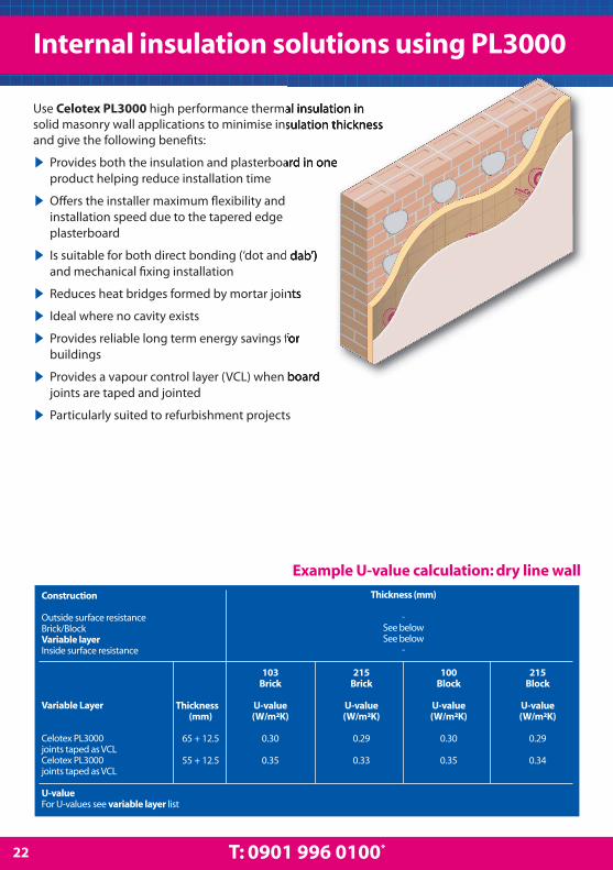
Use Celotex PL3000 high performance thermal insulation insolid masonry wall applications to minimise insulation thicknessand give the following benefits:
▶ Provides both the insulation and plasterboard in one product helping reduce installation time
▶ Offers the installer maximum flexibility and installation speed due to the tapered edge plasterboard
▶ Is suitable for both direct bonding (‘dot and dab’) and mechanical fixing installation
▶ Reduces heat bridges formed by mortar joints
▶ Ideal where no cavity exists
▶ Provides reliable long term energy savings for buildings
▶ Provides a vapour control layer (VCL) when board joints are taped and jointed
▶ Particularly suited to refurbishment projects
Internal insulation solutions using PL3000
Example U-value calculation: dry line wall
22 T: 0901 996 0100*
Construction
Outside surface resistanceBrick/BlockVariable layerInside surface resistance
Variable Layer
Celotex PL3000 joints taped as VCLCelotex PL3000joints taped as VCL
U-valueFor U-values see variable layer list
103 215 100 215Brick Brick Block Block
Thickness U-value U-value U-value U-value(mm) (W/m²K) (W/m²K) (W/m²K) (W/m²K)
65 + 12.5 0.30 0.29 0.30 0.29
55 + 12.5 0.35 0.33 0.35 0.34
Thickness (mm)
-See belowSee below
-

Installation guidelines
23celotex.co.uk
Installation guidelines for internal liningsystems using direct bonding
▶ Ensure that existing walls are permeable. Strip anygloss paint or vinyl wallpaper.
▶ Use the Celotex Insulation Saw to cut the 1200mm x2400mm Celotex PL3000 boards to fit the floor-to-ceiling height of the room.
▶ Ensure a continuous seal at skirting, ceiling level andat openings by applying a continuous band of gypsumadhesive. Gypsum adhesive at perimeter edges can bereplaced with thin timber battens.
▶ Apply further dabs of gypsum adhesive. This shouldbe in accordance with the adhesive manufacturer’sinstructions.
▶ Align sheets against the dabs and secure intocorrect position.
▶ Once the dabs are set, it is recommended thatadditional secondary fixings be applied to the CelotexPL3000. Exact fixing details should be in accordancewith the recommendations of the fixing manufacturer.
▶ Joints between the boards must be tightly butted,taped and jointed using appropriate tape and jointingmaterial to create the vapour control layer (VCL).
▶ Line window and door reveals with thinner CelotexTB3000 boards to reduce the risk of thermal bridging.Fix a batten around the edge of the opening and scribethe board to fit the reveal. Cut the dry lining to suit andmechanically fix into the masonry reveal usingproprietary fixings. Finish using an angle fillet at theframe and an angle bead or scrim tape at externalcorners.
▶ Please note that to avoid the load being directlyapplied to the Celotex PL3000, suitable mechanicalfixings should be used for other internal fittings. Adviceon suitable fixings should be sought directly from thefixing manufacturer.
▶ Please note that where existing walls are subject tothe ingress of excessive moisture, it is recommendedthat Celotex PL3000 should be installed usingmechanical fixings rather than a direct bondingtechnique.
Installation guidelines for internal liningsystems using mechanical fixings
▶ Ensure that existing walls are permeable. Strip anygloss paint or vinyl wallpaper.
▶ Use the Celotex Insulation Saw to cut the 1200mm x2400mm Celotex PL3000 boards to fit the floor-to-ceiling height of the room.
▶ Secure Celotex PL3000 with suitable mechanicalfixings. Fixing details should be in accordance with thefixing manufacturer’s instructions.
▶ Joints between the boards must be tightly butted,taped and jointed using appropriate tape and jointingmaterial to create the VCL.
▶ Line window and door reveals as for direct bondingtechnique in adjacent column.
Installation guidelines for internal liningsystems using mechanical fixings to timberbattens
▶ Ensure that existing walls are permeable. Strip anygloss paint or vinyl wallpaper.
▶ Fix treated softwood timber battens to the masonry.They should be set out a maximum of 600mm verticalcentres to coincide with the edges of the boards. As aminimum requirement, horizontal battens should beused to support the top and bottom of the boardedges
▶ Galvanised clout nails or timber drywall screwsshould then be used to fix the boards to the battens.Specific advice on suitable fixings should be sourceddirectly from the fixings manufacturer.
▶ Joints between the boards should be tightly buttedand finished by taping and jointing using appropriatetape and jointing material to create the VCL.
Installation guidelines for internal liningsystems using mechanical fixings to metallining systems
▶ Celotex PL3000 boards can be fixed to a number ofproprietary metal frame lining systems. The systemshould be fixed in accordance with the manufacturer’sinstructions.
Insu
lati
on so
luti
ons u
sing
pla
ster
boa
rd th
erm
al la
min
ate

Single timber frame wall lining and dormercheeks using PL3000
24 T: 0901 996 0100*
Celotex offers two solutions for single timber frame wall liningapplications. The first utilises the low lambda values of CelotexTB3000 or Celotex GA3000 between the studs, followed by aninternal lining of Celotex PL3000 over the studs. This solutiongives the thinnest build-up with better thermal insulationperformance. The Celotex PL3000 provides the over studinsulation and plasterboard in one product, helping reduce installation time.
The second option is to use mineral wool batts fitted between the studs, followed by an internal lining of Celotex PL3000 over the studs. This solution gives a thicker build-up but offers improved acoustic insulation.
Construction
Outside surface resistanceWeatherboard - Tiles - Rendered - Code 4 leadVentilated cavity batten air spaceBreather membranePlywoodCelotex between 100mm studs @ 400 ctrs (11.7% brg)Low E cavity between studs @ 400 ctrs (15% brg)Variable layer (for over studs)Inside surface resistance
Variable Layer
Celotex PL3000Celotex PL3000Celotex PL3000Celotex PL3000
Weatherboarding Tile Hung Rendered Lead CladThickness Thickness Thickness Thickness
(mm) (mm) (mm) (mm)- - - -
any any 20 1.825 n/a n/a 25- - - -
12 12 12 12†TB3040 TB3040 TB3040 TB3040
60 60 60 60
See below See below See below See below- - - -
Thickness U-value U-value U-value U-value(mm) (W/m²K) (W/m²K) (W/m²K) (W/m²K)
65 + 12.5 0.20 0.19 0.20 0.2055 + 12.5 0.21 0.21 0.22 0.2240 + 12.5 0.25 0.25 0.25 0.2525 + 12.5 0.30 0.30 0.30 0.30
TB = Celotex TB3000GA = Celotex GA3000Low E = Low emissivity
† When using lead clad, the plywood layer is moved to outside the ventilated batten airspace
Example U-value calculation: single timber frame wall
Rendered

▶Make sure all studs and rails are flush, with noprojections, and that services are correctly installed.
▶Fit Celotex insulation or mineral wool batts tightly in-between all studs and push up to plywoodsheathing.
▶For optimum thermal performance, the unprintedfoil surface should face the air cavity within thestudwork.
▶Cut boards for infill panels, using off-cuts wherepossible, making sure there are no air gaps at wallabutments.
▶ Install Celotex PL3000 insulation over the studs.
▶Tightly butt edges of boards together, making surethere are no gaps and fix back to solid timber, both atstud lines and at top and bottom rails.
▶ Joints between the boards must be tightly butted,taped and jointed using appropriate tape and jointingmaterial to create the vapour control layer (VCL).
▶Vapour seal all perimeter abutments using sealant.
▶Seal around all penetrations for electrical outlets andswitch boxes.
NB: Some building insurance companies may requireadditional third party approval when using insulationin timber frame applications. Advice should be soughtfrom the relevant parties prior to specifying theinsulation required. Celotex insulation is covered byBBA certificate number 09/4667. Please note thatCelotex FR4000 is not covered by this certificate.
Installation guidelines
25celotex.co.uk
Lead clad
Tile hung
Weatherboarding
Insu
lati
on so
luti
ons u
sing
pla
ster
boa
rd th
erm
al la
min
ate
also suitable for this application

Pitched roof sarkingThe loft space created by a pitched roof can bemade habitable by insulating along the plane ofthe roof pitch with Celotex rigid PIR insulationboards. This creates a warm, potentially habitableroof space in which water pipes and tanks nolonger need to be insulated.
When using over the roof structure as insulatingsarking, Celotex insulation creates a warm roofstructure and eliminates thermal bridging at therafters. The use of a single continuous layer ofinsulation over the rafters, in conjunction with avapour barrier on the underside of the rafters,eliminates the risk of condensation and avoidsthe need for ventilation of the rafter space.Where very low U-values are required, Celotexrecommends a two–layer system in order toreduce the racking forces on the fastenersrequired to fix counter battens to rafters. In thissystem, the first layer of insulation is applied as acomplete layer over the rafters. A second, thinnerlayer is then fitted over the first layer, betweenthe counter battens.
Insulation between and over raftersWhere headroom and rafter depth is limited,Celotex insulation may be fitted between andover the rafters. If this two-layer solution ischosen, it is important that the thermalresistance of the inner layer (between therafters), is less than, or of equal resistance to thatof the outer layer (over the rafters).
This reduces the risk of interstitial condensationbetween the insulation layers. The condensationrisk also depends upon occupancy and buildinguse. Celotex therefore recommends that acondensation risk analysis is obtained todetermine the optimum solution for individualprojects. Please contact the Celotex TechnicalCentre for further information.
Insulation solutions for pitched roofs
26 T: 0901 996 0100*

Insulation between raftersIf sarking felt is being used, a minimum 50mmventilation air space must be provided betweenthe felt and the cold side of the insulation inorder to minimise the risk of condensationformation. This is known as ventilatedconstruction.
If a breathable membrane is being used, allowthe membrane to sag between the rafterscreating an unventilated air gap ofapproximately 20mm between the membraneand the cold side of the insulation. However,when fixing counter battens for drainage overthe breathable membrane, it leaves the entirerafter depths to be filled with insulation.
The outer side of the membrane must beadjacent to an air space to allow moisturevapour to escape to the outside of the building.This is known as unventilated construction.
Insulation between and under raftersIf sarking felt is being used, a minimum 50mmventilation air space must be provided betweenthe felt and the cold side of the insulation inorder to minimise the risk of condensationformation. This is known as ventilatedconstruction.
If a breathable membrane is being used, allowthe membrane to sag between the rafterscreating an unventilated air gap ofapproximately 20mm between the membraneand the cold side of the insulation. However,when fixing counter battens for drainage overthe breathable membrane, it leaves the entirerafter depths to be filled with insulation.
The layer of insulation to the underside of therafters provides an effective barrier to moisturevapour and air leakage, when taping the boardjoints.
The outer side of the membrane must beadjacent to an air space to allow moisturevapour to escape to the outside of the building.This is known as unventilated construction.
27celotex.co.uk

Use Celotex TB3000, Celotex GA3000 and Celotex XR3000high performance thermal insulation in pitched roof sarkingapplications to minimise insulation thickness and give thefollowing benefits:
▶ Highly efficient ‘warm roof’ insulation over rafters
▶ Provides reliable long term energy savings for buildings
▶ Low emissivity foil facers give improved thermal insulation performance within cavity air spaces
▶ Eliminates thermal bridging
▶ Optional single layer system
▶ Ideal for new build or major refurbishment projects
▶ Air-tight construction method
Pitched roof sarking
Construction
Outside surface resistanceTiling including batten spaceBreather membraneCavity / counter battenCelotex TB3000 between 47 x 47 counterbattens @ 400 ctrsVariable layerCavity (low emissivity) rafter space (11.7% brg)Polythene 1000 gauge, VCLPlasterboardInside surface resistance
Thickness(mm)
---
22
25See below
150-
12.5-
U-valueFor U-values see variable layer list
Example U-value calculation: pitched roof sarking
Variable Layer
Celotex XR3000, over rafterCelotex XR3000, over rafterCelotex GA3000, over rafterCelotex GA3000, over rafterCelotex GA3000, over rafterCelotex GA3000, over rafterCelotex GA3000, over rafterCelotex GA3000, over rafterCelotex GA3000, over rafterCelotex GA3000, over rafterCelotex GA3000, over rafterCelotex TB3000, over rafter
Thickness(mm)
120110100908075706560555045
U-value(W/m2K)
0.140.150.160.170.180.190.200.200.210.220.240.25
28 T: 0901 996 0100*

▶Note that specific fixing requirements should bedetermined for each roof, taking into account roofdesign and location.
▶Fix a treated timber stop batten equal in thickness tothe Celotex insulation across the rafters at the eaves.Butt boards directly against this batten.
▶ Install Celotex insulation boards with the long sidesparallel to the rafter lines with both edges supportedby rafters.
▶For optimum thermal performance, the unprintedfoil surface should face adjacent air cavities.
▶Cut the boards using the Celotex Insulation Saw torake and splay at ridge and verges to ensure closebutted joints.
▶Use large headed nails to fix boards in placetemporarily until permanently secured by counterbattens.
▶Position a preservative-treated timber counterbatten (minimum 38mm x 50mm) over the insulationon the line of each rafter. Nail the lower end of eachcounter batten directly into the stop batten.
▶Calculate the length of the stainless steel helicalspike fixings required by adding together the counterbatten depth, the insulation thickness and depth ofpenetration required to the rafter (usually minimum38mm).
▶Stainless steel helical spikes have been specificallydeveloped for ‘warm’ pitched roofs and are especiallyappropriate for use with pre-trussed rafterconstructions, allowing a much thinner gauge offastener to be used, thus reducing the risk of splittingtimber battens or rafters.
▶Fix at maximum 400mm centres along the counterbatten. Pre-drill pilot holes in the counter battens toensure ease of nailing and to reduce the possiblesplitting of the timber.
▶ If using a two layer system, cut a second layer ofboard with the Celotex Insulation Saw (the boardshould be at least 13mm less than the counter battenthickness allowing for the breather membrane to sag)to fit between the counter battens.
▶Drape a breather membrane over the counterbattens and secure with tile battens.
▶Fix the tile battens to the counter batten at anappropriate gauge to suit the slates or tiles selected.
▶A variety of eaves and verge details may be achievedwith this system. Eaves and soffit ventilators are notgenerally required.
▶A vapour control layer (VCL) should be installed tothe underside of the rafters.
▶Finish with plasterboard or other suitable sheetmaterial fixed to the rafters.
▶Where exposed rafters are required, plasterboard (orany other suitable decorative board) may be laid overthe rafters before fixing the insulation. Select longerfasteners to suit. Plasterboard should be protectedfrom rain during the installation. A polythene vapourcontrol layer (VCL) must be installed directly over theplasterboard.
Insu
lati
on s
olu
tion
s fo
rp
itch
ed ro
ofs
Installation guidelines
29celotex.co.uk
also suitable for this application

Insulation between and over rafters
Construction
Outside surface resistanceTiling including batten spaceCounter battenBreather membraneVariable layerCelotex TB3000 between rafters @ 400 ctrs(11.7% brg)Cavity (low emissivity) rafter spacePolythene 1000 gauge, VCLPlasterboardInside surface resistance
Thickness(mm)
--
38-
See below
40110
-12.5
-
Variable Layer
Celotex GA3000 over rafterCelotex GA3000 over rafterCelotex GA3000 over rafterCelotex GA3000 over rafterCelotex GA3000 over rafterCelotex GA3000 over rafterCelotex GA3000 over rafterCelotex GA3000 over rafterCelotex GA3000 over rafterCelotex TB3000 over rafter
Thickness(mm)
100908075706560555045
U-value(W/m2K)
0.150.170.180.190.190.200.210.220.230.25
U-value
For U-values see variable layer list
Use Celotex TB3000 or Celotex GA3000 high performancethermal insulation in pitched roof between and over rafterapplications to minimise insulation thickness and give thefollowing benefits:
▶ Ideal for use where headroom is limited
▶ Provides reliable long term energy savings for buildings
▶ Creates a warm, habitable roof space
▶ No need to insulate water pipes and tanks
▶ Suitable for new build and major refurbishment projects
▶ Minimised additional loading to the structure
Example U-value calculation: between and over rafters
30 T: 0901 996 0100*

Insulation over the rafters
▶Note that specific fixing requirements should bedetermined for each roof, taking into account roofdesign and location.
▶Fix a treated timber stop batten equal in thickness tothe Celotex insulation across the rafters at the eaves.Butt boards directly against this batten.
▶ Install Celotex insulation boards with both edgessupported by the rafters.
▶Cut the boards using the Celotex Insulation Saw torake and splay at ridge and verges to ensure closebutted joints.
▶Use large headed nails to temporarily fix board inplace, until permanently secured by counter battens.
▶ Install a breather membrane over the insulation.
▶Position a preservative-treated timber counterbatten (minimum 38mm x 50mm) over the breathermembrane and insulation on the line of each rafter.Nail the lower end of each counter batten directly intothe stop batten.
▶Calculate the length of the suitable fixings requiredby adding together the counter batten depth, theinsulation thickness and depth of penetration requiredto the rafter (usually minimum 38mm).
▶Fix at maximum 400mm centres along the counterbatten. Pre-drill pilot holes in the counter battens toensure ease of nailing and to reduce the possiblesplitting of the timber.
▶Fix the tile battens to the counter battens at anappropriate gauge to suit the slates or tiles selected.
Insulation between the rafters
▶For optimum thermal performance the unprintedfoil surface should face the rafter air cavity.
▶Accurately measure the width to be filled betweenthe inside face of the rafters, prior to cutting the board.
▶Use the Celotex Insulation Saw to cut the Celotexboard at a slight angle, making the board width slightlyoversized on one surface to achieve a ‘friction fit’.
▶Push the board into the void between the raftersuntil it is tight against the underside of the first layer of insulation.
▶To hold the boards in place, use battens along theside of the rafters.
▶Tightly fit the insulation to the ridge plate and carryover and tightly butt the wall plate at eaves.
▶A vapour control layer (VCL) should be installed tothe underside of the rafters. A polythene sheet ofhigher vapour resistance is recommended for highhumidity areas such as kitchens or bathrooms.
▶Finish with plasterboard or other suitable sheetmaterial, fixed to the rafters.
NB: This solution is not suitable for exposed rafters.Where exposed rafters are required, please refer to thepitched roof sarking application on pages 28 and 29.
Installation guidelines
31celotex.co.uk
Insu
lati
on s
olu
tion
s fo
rp
itch
ed ro
ofs
also suitable for this application
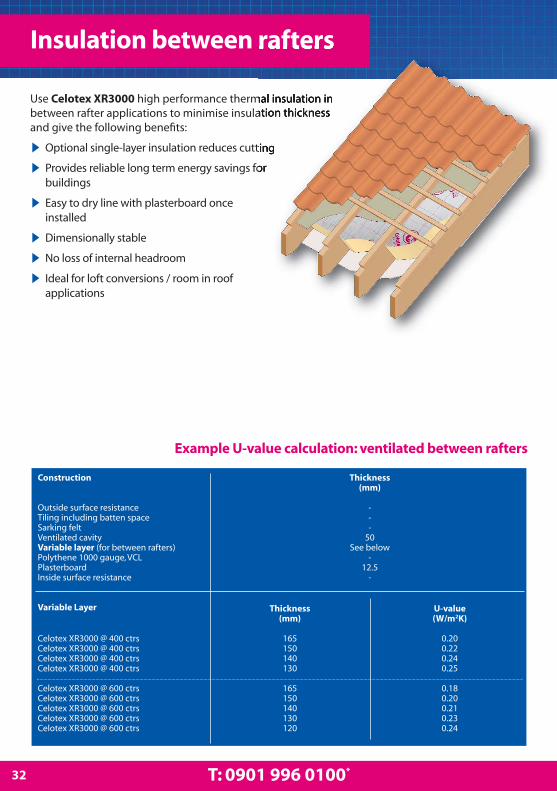
Use Celotex XR3000 high performance thermal insulation inbetween rafter applications to minimise insulation thicknessand give the following benefits:
▶ Optional single-layer insulation reduces cutting
▶ Provides reliable long term energy savings for buildings
▶ Easy to dry line with plasterboard once installed
▶ Dimensionally stable
▶ No loss of internal headroom
▶ Ideal for loft conversions / room in roof applications
Insulation between rafters
Example U-value calculation: ventilated between rafters
32 T: 0901 996 0100*
Construction
Outside surface resistanceTiling including batten spaceSarking feltVentilated cavityVariable layer (for between rafters) Polythene 1000 gauge, VCLPlasterboardInside surface resistance
Variable Layer
Thickness(mm)
---
50See below
-12.5
-
Celotex XR3000 @ 400 ctrsCelotex XR3000 @ 400 ctrsCelotex XR3000 @ 400 ctrsCelotex XR3000 @ 400 ctrs
Celotex XR3000 @ 600 ctrsCelotex XR3000 @ 600 ctrsCelotex XR3000 @ 600 ctrsCelotex XR3000 @ 600 ctrsCelotex XR3000 @ 600 ctrs
Thickness(mm)
165150140130
165150140130120
U-value(W/m2K)
0.200.220.240.25
0.180.200.210.230.24

Installation guidelines: ventilated
▶Make sure there is enough rafter depth toaccommodate not only the thickness of the Celotexinsulation but also a 50mm ventilated airspace abovethe boards.
▶Fix battens to the inside face of the rafter so that thebottom of the batten is 50mm below the sarking felt.
Installation guidelines: unventilated
▶Make sure there is enough rafter depth toaccommodate not only the thickness of the Celotexinsulation, but also a minimum 20mm drape space forthe breathable membrane.
▶Fix battens to the inside face of the rafters, to ensurethat the drape space is maintained.
▶Alternatively, counter battens can be fixed over thebreathable membrane to provide a channel formoisture run off. The whole depth of the rafter canthen be filled with insulation.
▶All details are to be in accordance with themembrane manufacturers details.
Installation guidelines: ventilated &unventilated
▶Measure the space to be filled between the insideface of the rafter prior to cutting the board.
▶Use the Celotex Insulation Saw to cut the boards at aslight angle, making the board width slightly oversizedon one surface to achieve a ‘friction fit’.
▶Push the boards into the void between the raftersuntil they are tight up to the battens or the membrane, ensuring that lateral joints are closely butted.
▶Tightly fit the insulation to the ridge plate and carryover and tightly butt the wall plate at eaves.
▶A vapour control layer (VCL) should be installed tothe underside of the rafters. A polythene sheet ofhigher vapour resistance is recommended for highhumidity areas such as kitchens or bathrooms.
▶Complete the internal finish with plasterboard orother suitable sheet material.
Installation guidelines
33celotex.co.uk
Construction
Outside surface resistanceTiling including batten spaceBreather membraneLow E cavity, remainder of rafter depthVariable layer (for between rafters)Polythene, 1000 gauge VCLPlasterboardInside surface resistance
Variable Layer
Celotex XR3000 @ 400 ctrsCelotex XR3000 @ 400 ctrsCelotex XR3000 @ 400 ctrsCelotex XR3000 @ 400 ctrs
Celotex XR3000 @ 600 ctrsCelotex XR3000 @ 600 ctrsCelotex XR3000 @ 600 ctrsCelotex XR3000 @ 600 ctrs
200 mm deep rafters 175 mm deep rafters 150 mm deep raftersThickness Thickness Thickness
(mm) (mm) (mm)- - -- - -- - -
Various Various VariousSee below See below See below
- - -12.5 12.5 12.5
- - -
Thickness U-value U-value U-value(mm) (W/m²K) (W/m²K) (W/m²K)165* 0.18 0.19 n/a150 0.20 0.20 0.21*140 0.20 0.21 0.22*130 0.21 0.21 0.23
165* 0.17 0.17 0.20150 0.18 0.18 0.21140* 0.19 0.19 0.22130 0.20 0.20 0.22
Example U-value calculation: unventilated between rafters
Insu
lati
on s
olu
tion
s fo
rp
itch
ed ro
ofs
* = Counter batten over membrane - see guidelines below
also suitable for this application

Use Celotex TB3000, Celotex GA3000 and Celotex XR3000 highperformance thermal insulation in pitched roof between andunder rafter applications to minimise insulation thicknessand give the following benefits:
▶ Ideal for use with shallow rafters
▶ Provides reliable long term energy savings for buildings
▶ Minimised additional loading to the structure
▶ Dimensionally stable
▶ Ideal for loft conversions / room in roof applications
▶ Upgrade existing ceilings to current standards
Insulation between and under rafters
Construction
Outside surface resistanceTiling including batten spaceBreather membraneLow E cavity, between rafters (11.7% brg)Celotex between rafters @ 400 Ctrs (11.7% brg)Variable layer (for below rafters)PlasterboardInside surface resistance
Variable Layer
Celotex TB3000 joints taped as VCLCelotex TB3000 joints taped as VCLCelotex TB3000 joints taped as VCLCelotex TB3000 joints taped as VCLCelotex TB3000 joints taped as VCLCelotex TB3000 joints taped as VCLCelotex TB3000 joints taped as VCL
100 mm deep rafters 125 mm deep rafters 150 mm deep raftersThickness Thickness Thickness
(mm) (mm) (mm)- - -- - -- - -
20 25 30GA3080 GA3100 XR3120
See below See below See below12.5 12.5 12.5
- - -
Thickness U-value U-value U-value(mm) (W/m²K) (W/m²K) (W/m²K)
45 0.19 0.17 0.1540 0.20 0.18 0.1635 0.21 0.18 0.1630 0.22 0.19 0.1725 0.23 0.20 0.1820 0.24 0.21 0.1912 - 0.23 0.20
GA = Celotex GA3000XR = Celotex XR3000Low E = Low emissivityVCL = Vapour control layer
Example U-value calculation: unventilated between and under rafters
34 T: 0901 996 0100*

Construction
Outside surface resistanceTiling including batten spaceSarking feltVentilated cavityCelotex between rafters @ 400 Ctrs (11.7% brg)Variable layer (for below rafters)Low E cavity batten air space See Note 1PlasterboardInside surface resistance
Variable Layer
Celotex GA3000 joints taped as VCLCelotex GA3000 joints taped as VCLCelotex GA3000 joints taped as VCLCelotex TB3000 joints taped as VCLCelotex TB3000 joints taped as VCLCelotex TB3000 joints taped as VCLCelotex TB3000 joints taped as VCLCelotex TB3000 joints taped as VCLCelotex TB3000 joints taped as VCL
100 mm deep rafters 125 mm deep rafters 150 mm deep raftersThickness Thickness Thickness
(mm) (mm) (mm)- - -- - -- - -
50 50 50GA3050 GA3075 GA3100
See below See below See below25 25 25
12.5 12.5 12.5- - -
Thickness U-value U-value U-value(mm) (W/m²K) (W/m²K) (W/m²K)
60 0.20* 0.17* 0.15*55 0.21* 0.18* 0.16*50 0.22* 0.19* 0.16*45 0.23* 0.21 0.1840 0.25* 0.23 0.1935 - 0.24 0.2030 - 0.25 0.2125 - - 0.2220 - - 0.23
GA = Celotex GA3000Low E = Low emissivityVCL = Vapour control layer
Example U-value calculation: ventilated between and under rafters
Installation guidelines: ventilated
▶Make sure there is enough rafter depth to accommodatenot only the thickness of the Celotex insulation but also a50mm ventilated airspace above the boards.
▶Fix battens to the inside face of the rafter so that thebottom of the batten is 50mm below the sarking felt.
Installation guidelines: unventilated
▶Make sure there is enough rafter depth toaccommodate not only the thickness of the Celotexinsulation, but also a minimum 20mm drape space forthe breathable membrane.
▶Fix battens to the inside face of the rafters, to ensurethat the drape space is maintained.
▶Alternatively, counter battens can be fixed over thebreathable membrane to provide a channel formoisture run off. The whole depth of the rafter can thenbe filled with insulation.
▶All details are to be in accordance with themembrane manufacturers details.
Installation guidelines: ventilated & unventilated
▶Measure the space to be filled between the inside face ofthe rafter prior to cutting the board.
▶Use the Celotex Insulation Saw to cut the boards at aslight angle, making the board width slightly oversized onone surface to achieve a ‘friction fit’. Celotex insulation clipsshould also be used to hold the board in place. See page 15for more information.
▶Push the boards into the void between the rafters untilthey are tight up to the battens or the membrane, ensuringthat lateral joints are closely butted. Secure the second layerof Celotex insulation to the underside of the rafters withbroad-headed clout nails. Joints between boards must betightly butted.
▶Seal the board joints with Celotex Insulation Tape.Vapour seal all perimeter abutments using sealant.
▶Nail or screw plasterboard or other lining through theinsulation to the rafter, ensuring that the length of thefasteners is adequate to secure the plasterboard lining.
▶Alternatively, fit softwood battens to the underside of theinsulation fixed through to the rafters, and then fix theplasterboard directly to the batten. This also provides a voidfor services.
Installation guidelines
35celotex.co.uk
Insu
lati
on s
olu
tion
s fo
rp
itch
ed ro
ofs
* This thickness of board is recommended to be fixed using 25mm x 47mmbattens to allow a suitable construction detail Note 1: Use 25mm x 47mm battens to create a low emissivity cavity air space
also suitable for this application
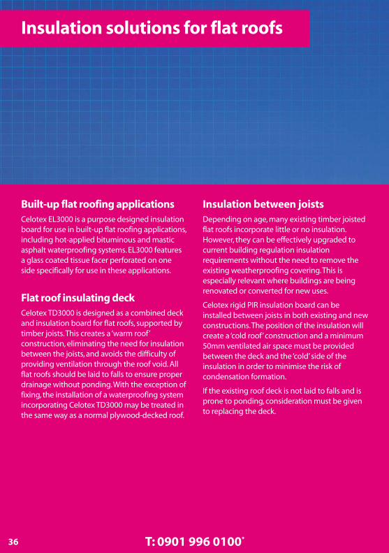
Built-up flat roofing applicationsCelotex EL3000 is a purpose designed insulationboard for use in built-up flat roofing applications,including hot-applied bituminous and masticasphalt waterproofing systems. EL3000 featuresa glass coated tissue facer perforated on oneside specifically for use in these applications.
Flat roof insulating deckCelotex TD3000 is designed as a combined deckand insulation board for flat roofs, supported bytimber joists. This creates a ‘warm roof’construction, eliminating the need for insulationbetween the joists, and avoids the difficulty ofproviding ventilation through the roof void. Allflat roofs should be laid to falls to ensure properdrainage without ponding. With the exception offixing, the installation of a waterproofing systemincorporating Celotex TD3000 may be treated inthe same way as a normal plywood-decked roof.
Insulation between joistsDepending on age, many existing timber joistedflat roofs incorporate little or no insulation.However, they can be effectively upgraded tocurrent building regulation insulationrequirements without the need to remove theexisting weatherproofing covering. This isespecially relevant where buildings are beingrenovated or converted for new uses.
Celotex rigid PIR insulation board can beinstalled between joists in both existing and newconstructions. The position of the insulation willcreate a ‘cold roof’ construction and a minimum50mm ventilated air space must be providedbetween the deck and the ‘cold’ side of theinsulation in order to minimise the risk ofcondensation formation.
If the existing roof deck is not laid to falls and isprone to ponding, consideration must be givento replacing the deck.
Insulation solutions for flat roofs
36 T: 0901 996 0100*

Insulation between and under joistsDepending on age, many existing timber joistedflat roofs incorporate little or no insulation.However, they can be effectively upgraded tocurrent building regulation insulationrequirements without the need to remove theexisting weatherproofing covering. This isespecially relevant where buildings are beingrenovated or converted for new uses.
Celotex rigid PIR insulation board can beinstalled between and under joists in bothexisting and new constructions. The position ofthe insulation will create a ‘cold roof’construction and a minimum 50mm ventilatedair space must be provided between the deckand the ‘cold’ side of the insulation in order tominimise the risk of condensation formation.
If the existing roof deck is not laid to falls and isprone to ponding, consideration must be givento replacing the deck.
37celotex.co.uk
For more flat roofingapplications, please see theCelotex Flat Roof Handy Guide.
Download your copy at
celotex.co.uk

Construction Concrete Concrete Steel Steel Timber TimberDeck Deck Deck Deck Deck DeckFully Mechanically Fully Mechanically Fully Mechanically
Bonded Fixed Bonded Fixed Bonded FixedThickness Thickness Thickness Thickness Thickness Thickness
(mm) (mm) (mm) (mm) (mm) (mm)Outside surface resistance - - - - - -Built-up roofing 12 12 12 12 12 12Variable layer See below See below See below See below See below See belowPolythene 1000 gauge, VCL - - - - - -Concrete deck 250 250 n/a n/a n/a n/aSteel deck n/a n/a 1.5 1.5 n/a n/aTimber deck plywood n/a n/a n/a n/a 19 19Cavity between joist at 11.7% bridging n/a n/a n/a n/a 150 150Plasterboard n/a n/a n/a n/a 12.5 12.5Inside surface resistance - - - - - -
Variable Layer Thickness U-value U-value U-value U-value U-value U-value(mm) W/m2K W/m2K W/m2K W/m2K W/m2K W/m2K
Celotex EL3000 200 0.12 0.14 0.12 0.15 0.12 0.14Celotex EL3000 165 0.14 0.17 0.15 0.17 0.14 0.16Celotex EL3000 150 0.16 0.18 0.16 0.19 0.15 0.18Celotex EL3000 140 0.17 0.19 0.17 0.20 0.16 0.19Celotex EL3000 120 0.19 0.22 0.20 0.22 0.18 0.21Celotex EL3000 110 0.22 0.24 0.22 0.25 0.21 0.23Celotex EL3000 100 0.24 0.26 0.25 0.27 0.22 0.25Celotex EL3000 90 0.26 0.29 0.27 0.30 0.24 0.27Celotex EL3000 80 0.29 0.31 0.30 0.33 0.27 0.30Celotex EL3000 50 0.45 0.47 0.48 0.51 0.40 0.43
Built-up flat roofing applications
38 T: 0901 996 0100*
Example U-value calculation: warm flat roof - built-up roofing
Use Celotex EL3000 high performance insulation inbuilt-up flat roofing applications, including hot-applied bituminous and mastic asphaltwaterproofing systems and fully adhered single-plymembranes. The perforated facer is suitable forbonding in mastic asphalt applications and hotapplied bituminous built-up roofing systems. Theunperforated reverse facer is suitable for single-ply,fully adhered roof systems, self-adhesivemembranes and liquid-applied membranes.
When designing a flat roof using Celotex EL3000boards, three basic principles apply:
1.Design to a fall of 1:80, 1:60 or 1:40 as appropriateto the weathering system, type of deck andconstruction tolerances.
2.Have due regard for the use and design of thebuilding and the need to ensure that the design will
not allow a build up of moisture below thewaterproofing membrane.
3.Provide adequate protection for both insulationand waterproofing if significant foot traffic isexpected either during or after the completion ofthe roof.
Installation guidelinesHot-applied systemsThe felt vapour control layer (VCL) in accordance with
BS 6229 should be fully sealed at all laps prior to
applying the insulation. At perimeters and abutments
the VCL should be turned up around the insulation
board edges and a flap of approximately 300mm
should be bonded to the top surface of the insulation
board. The VCL should be fully bonded to concrete
decks using hot bitumen adhesive, strip-bonded to the
ribs of metal decks and partially bonded to timber
decks. On timber decks the VCL may be nailed to the
deck, but laps should be sealed with the appropriate
adhesive.
When used on metal decks, Celotex EL3000 boards
should be laid with the perforated facer uppermost
and the long sides at right angles to the corrugations
and bonded in a full mop of hot bitumen to the VCL.
Torch-on technique is suitable only when there is no
direct contact between the flame and the board.
EL3000 is not suitable for use with the standard
torch-on technique.
Mechanical fastening
The boards should be laid with all joints tightly butted
over the VCL and then mechanically secured through
to the deck. When used on metal decks, these roof
boards should be laid with the long edges at right
angles to the corrugations. When mechanical fasteners
are utilised, they should be selected to suit the type of
deck used. Celotex recommends the use of thermally
broken fixings with plate washers of a surface area of
not less than 45cm². Fasteners should be installed
between 50mm – 150mm from the edges and corners
of the board.
The exact number of fixings required for each zone on
a flat roof must be calculated by the use of either BS
6399: Part 2: 1997 Code of Practice for Wind Loads, or
EN1991-1-4 used with the UK National Annex. A
minimum of 6 fixings per board must be used. Where
more than 6 fixings per board are required by the wind
uplift calculation, the higher figure must be adopted.
Further guidance on fixings and patterns can be
sought from fixing manufacturers and in the BRUFMA
information document on mechanical fixings for rigid
PIR roofboards.
Installation of weathering systems
Different types of weathering systems require different
installation instructions and guidelines. Advice on the
installation of these weathering systems should be
sought from the manufacturer or provider of the
weathering system type.
Laying pattern
It is recommended that boards are laid with joints
break-bonded.
Supporting deck
The supporting deck must provide adequate support
for the VCL and insulation board with joints being
supported by the ridges of the deck. It must be
capable of supporting the static and dynamic design
loads and the loads designed associated with the
construction activity without deflection in excess of
the limits defined in BS 6399:Part1. The deck must be
structurally sound, dry, clean and where necessary,
primed before application of the weathering and
insulating system.
Trafficking
Boards are capable of withstanding the trafficking
associated with normal roof laying work. However,
roofs are generally designed for only occasional
lightweight foot traffic or maintenance access. Where
more frequent or heavier access is required, protective
walkways should be provided. Under no circumstances
should the roof be used as a working platform, either
during or after the construction programme. Extra care
should be taken to protect the insulation and
weathering when ballasting.
Use of adhesives
When using adhesives, the installer should take care
not to use products that contain chemicals likely to
attack the insulating foam such as ketonic solvents.
Celotex EL3000 contains no chemicals or solvents
likely to damage the PVC membrane. When using
adhesives, the installer should check the compatibility
of the adhesive with the adhesive manufacturer.
39celotex.co.uk
Celotex EL3000over concrete deck -
perforated facer uppermost
Celotex EL3000over timber deck -
perforated facer uppermost
Insu
lati
on s
olu
tion
s fo
r fla
t ro
ofs
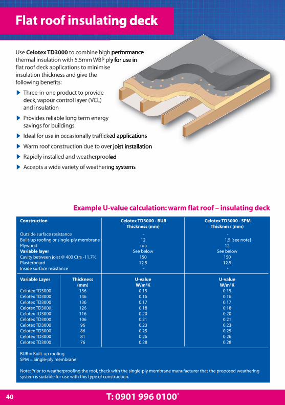
40 T: 0901 996 0100*
Example U-value calculation: warm flat roof – insulating deck
Flat roof insulating deck
Use Celotex TD3000 to combine high performancethermal insulation with 5.5mm WBP ply for use inflat roof deck applications to minimiseinsulation thickness and give thefollowing benefits:
▶ Three-in-one product to provide deck, vapour control layer (VCL) and insulation
▶ Provides reliable long term energy savings for buildings
▶ Ideal for use in occasionally trafficked applications
▶ Warm roof construction due to over joist installation
▶ Rapidly installed and weatherproofed
▶ Accepts a wide variety of weathering systems
Construction Celotex TD3000 - BUR Celotex TD3000 - SPMThickness (mm) Thickness (mm)
Outside surface resistance - - Built-up roofing or single-ply membrane 12 1.5 [see note]Plywood n/a 12Variable layer See below See belowCavity between joist @ 400 Ctrs -11.7% 150 150Plasterboard 12.5 12.5Inside surface resistance - -
Variable Layer Thickness U-value U-value (mm) W/m²K W/m²K
Celotex TD3000 156 0.15 0.15Celotex TD3000 146 0.16 0.16Celotex TD3000 136 0.17 0.17Celotex TD3000 126 0.18 0.18Celotex TD3000 116 0.20 0.20Celotex TD3000 106 0.21 0.21Celotex TD3000 96 0.23 0.23Celotex TD3000 86 0.25 0.25Celotex TD3000 81 0.26 0.26Celotex TD3000 76 0.28 0.28
BUR = Built-up roofingSPM = Single-ply membrane
Note: Prior to weatherproofing the roof, check with the single-ply membrane manufacturer that the proposed weatheringsystem is suitable for use with this type of construction.

41celotex.co.uk
▶ Ensure that joist spacing is at no more than 600mmcentres and that the dimension of the joist is sufficientto span and accept additional loads. If asphaltweathering is to be used, joists should be at no morethan 400mm centres.
▶ Install the insulation boards, ensuring that the longedges are parallel to the line of the joists. 50mm x50mm cross noggings should be inserted betweenjoists to support the short edges of the boards.
▶Where boards butt together, bed onto twin beads ofvapour sealant wide enough to accommodate thisarrangement. This completes the vapour control layer(VCL) when combined with each board’s foil facings.
▶ Lay the boards with the plywood side uppermostand stagger board joints. Leave a gap of approximately2mm between boards and ensure a minimum 20mmbearing on joists and noggins.
▶ Fix Celotex TD3000 with corrosion-proof SuretwistComposite Panel helical fasteners at a frequency to suitthe design wind load. Refer to BS 6399-2 Code ofPractice for Wind Loads. A minimum of 16 fasteners perboard will resist a wind load of 2.22 KN/m2 based on adesign load of 0.4KN per fastener.
▶ Ensure that fixings are no less than 10mm in fromthe board edge or 50mm from each corner. Theyshould be equally spaced along the supporting joists.Fixings should be long enough to penetrate at least38mm into the supporting timber.
▶ Stagger opposing fixings where two board edgesshare the same joist or noggin.
▶ Provide a complete insulation envelope byextending the wall insulation board up to theunderside of the roof deck.
▶ Provide a soffit or ceiling below the joists, as thesurface of the product is not designed to be used as adecorative internal finish.
▶ Ensure that the plywood is completely dry beforeany weathering system is applied.
▶ Always use a Type 3G felt to BS 747 as a vapourdiffusion first layer when using BUR weatheringsystems. When using a single-ply membrane,additional 12mm plywood has to be applied on top ofthe Celotex TD3000.
▶ Temporary protection must be provided for both theinsulation and the waterproofing, if significant foottraffic is anticipated either during or after installation.
Falls
The structure should be designed so that the finishedroof has a continuous, smooth and even slope towardsthe rainwater outlet or gutter. The minimum fall shouldbe 1:80 to avoid ponding water.
Deck stability
Celotex TD3000 incorporates exterior grade WBPplywood to BS 1203, laminated to the surface. Thisgives the product excellent strength. Boards can spanup to 600mm joist centres to provide a suitablesubstrate for a variety of weathering systems.
Vapour control layer
Celotex TD3000 has a built-in VCL due to the board’sfoil facer, but this is discontinuous at the board joints.Therefore, a twin bead of vapour sealant should beapplied to the top of the supporting joists and nogginsat all board joints. This completes the VCL whencombined with each board’s foil facers.
Installation guidelines
Insu
lati
on s
olu
tion
s fo
r fla
t ro
ofs
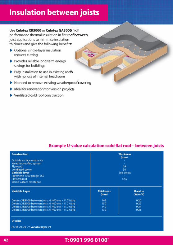
42 T: 0901 996 0100*
Use Celotex XR3000 or Celotex GA3000 highperformance thermal insulation in flat roof betweenjoist applications to minimise insulationthickness and give the following benefits:
▶ Optional single-layer insulation reduces cutting
▶ Provides reliable long term energy savings for buildings
▶ Easy installation to use in existing roofs with no loss of internal headroom
▶ No need to remove existing weatherproof covering
▶ Ideal for renovation/conversion projects
▶ Ventilated cold roof construction
Construction Thickness(mm)
Outside surface resistance -Weatherproofing system -Plywood 19Ventilated cavity 50Variable layer See belowPolythene 1000 gauge, VCL -Plasterboard 12.5Inside surface resistance -
Variable Layer Thickness U-value (mm) (W/m2K)
Celotex XR3000 between joists @ 400 ctrs - 11.7%brg 165 0.20Celotex XR3000 between joists @ 400 ctrs - 11.7%brg 150 0.22Celotex XR3000 between joists @ 400 ctrs - 11.7%brg 140 0.24Celotex XR3000 between joists @ 400 ctrs - 11.7%brg 130 0.25
Example U-value calculation: cold flat roof – between joists
Insulation between joists
U-value
For U-values see variable layer list

43celotex.co.uk
▶Make sure that there is enough joist depth toaccommodate not only the thickness of the Celotexinsulation, but also a 50mm ventilated airspace abovethe boards.
▶Fix battens to the inside face of the joists so that thebottom of the batten is 50mm below the decking.
▶Measure the space to be filled between the insideface of the joists prior to cutting the board, then cutthe board using the Celotex Insulation Saw.
▶The patented Celotex insulation clip is designed toallow insulation boards to be installed between timberjoists quickly and without nails or screws.
▶Fit the clips at one metre maximum centres alongthe edge of the insulation (for further informationabout the Celotex Insulation Clip and its use, pleaserefer to page 15).
▶Push the boards into the void between the joistsuntil they are tight up to the underside of stop battens,ensuring that the lateral joints are tightly butted.
▶A vapour control layer (VCL) should be installed tothe underside of the joists. For high humidity areassuch as kitchens and bathrooms, a polythene sheet ofhigher vapour resistance is recommended.
▶Complete the internal finish with plasterboard orother suitable sheet material screwed or nailed to thejoists.
When updating an existing ceiling, the Celotexinsulation can be fitted directly underneath the ceiling,providing there is no vapour check layer such as glosspaint or foil backed plasterboard.
Always ensure that there is a 50mm minimumventilation gap above any original insulation.Ventilation must be provided above an insulatedceiling directly through the cold void. Failure to do socould result in serious condensation problems thatmay lead to decay and possible failure.
Installation guidelines
Insu
lati
on s
olu
tion
s fo
r fla
t ro
ofs
also suitable for this application

Use Celotex TB3000, Celotex GA3000 or CelotexXR3000 high performance thermal insulation in flatroof between and under joist applications tominimise insulation thickness and givethe following benefits:
▶ A perfect solution to upgrade older buildings
▶ Provides reliable long term energy savings for buildings
▶ No need to remove existing weatherproofing covering
▶ Ventilated cold roof construction
▶ The ideal renovation/conversion solution
▶ Easy to minimise any loss of internal headroom
44 T: 0901 996 0100*
Insulation between and under joists
Construction
Outside surface resistanceWeatherproofing systemPlywoodVentilated cavityCelotex between joists @ 400 Ctrs - 11.7%brgVariable layer (for below joists)Low E cavity batten air space - 11.7%brgVapour control layerPlasterboardInside surface resistance
Variable Layer
Celotex GA3000Celotex TB3000Celotex TB3000Celotex TB3000Celotex TB3000Celotex TB3000Celotex TB3000Celotex TB3000
125mm deep joists 150mm deep joists 175mm deep joistsThickness Thickness Thickness
(mm) (mm) (mm)- - -
n/a n/a n/a19 19 1950 50 50
GA3075 GA3100 XR3120See below See below See below
See Note 1 25 25 25- - -
12.5 12.5 12.5- - -
Thickness U-value U-value U-value(mm) (W/m²K) (W/m²K) (W/m²K)
50 0.19* 0.16* 0.15*45 0.21 0.18 0.1740 0.23 0.19 0.1735 0.24 0.20 0.1830 0.25 0.21 0.1925 n/a 0.22 0.2020 n/a 0.23 0.2112 n/a n/a 0.22
GA = Celotex GA3000XR = Celotex XR3000Low E = Low emissivity
Example U-value calculation: cold flat roof – between and under joists
* This thickness of board is required to be fixed using 25mm x 47mm battensto allow a suitable construction detail Note 1: Use 25mm x 47mm battens to create a low emissivity air space
45celotex.co.uk
▶Make sure that there is enough joist depth toaccommodate not only the thickness of the Celotexinsulation, but also a 50mm ventilated airspace abovethe boards.
▶Fix battens to the inside face of the joists so that thebottom of the batten is 50mm below the decking.
▶Measure the space to be filled between the insideface of the joists prior to cutting the board, then cutthe board using the Celotex Insulation Saw.
▶The patented Celotex insulation clip is designed toallow insulation boards to be installed betweentimber joists quickly and without nails or screws.
▶Fit the clips at one metre maximum centres alongthe edge of the insulation (for further informationabout the Celotex Insulation Clip and its use, pleaserefer to page 15).
▶Push the boards into the void between the joistsuntil they are tight up to the underside of the stop battens, ensuring the lateral joints are tightly butted.
▶Secure the second layer of Celotex insulation to theunderside of the joists with broad-headed clout nails.
▶ Joints between boards must be tightly butted andsealed with Celotex Insulation Tape to create a vapourseal.
▶Clearly mark rafter-lines on the board face, using aspirit based felt-tip marker.
▶Nail or screw plasterboard or other lining throughthe insulation to the joist.
Composite systems can be used to combine Celotexinsulation under joist lining with a quilt type insulantbetween the joists which will provide acoustic, as wellas thermal insulation. This option is particularly usefulwhen upgrading to modern acoustic insulationstandards.
When updating an existing ceiling, the Celotexinsulation can be fitted directly underneath theceiling, providing there is no vapour check layerpresent such as gloss paint or foil backedplasterboard.
Always ensure that there is a 50mm minimumventilation gap above any original insulation.Ventilation must be provided above an insulatedceiling directly through the cold void. Failure to do socould result in serious condensation problems thatmay lead to decay and possible failure.
Installation guidelines
Insu
lati
on s
olu
tion
s fo
rfl
at ro
ofs
also suitable for this application

Masonry cavity wallsFor most of the past century, external masonrywalls have been predominantly of cavityconstruction. A cavity provides an effectivebarrier to rain penetration and also adds to thethermal resistance of the wall.
Modern energy conservation requirementsdemand added thermal insulation in externalwalls, and the cavity offers the most obviouslocation for the insulation. However, full cavity fillmay reintroduce the risk of moisture penetrationand many designers, especially when consideringexposed sites, prefer to specify partial-fillinsulation.
For partial-fill design to achieve high standards ofinsulation without a massive increase in the widthof the cavity and of the overall wall thickness,highly efficient insulation, like Celotex CW3000,must be used.
Solid masonry wallsInternal Insulation Solutions
Many older properties are constructed with solidmasonry walls which provide poor levels ofthermal insulation. These walls can besuccessfully insulated by incorporating Celotexinsulation as part of an internal lining system oran external render system.
The internal lining system creates internal wall
surfaces with low thermal mass. These will rapidlyrespond to changes in heat inputs and thissystem may be beneficial where a building orroom is only occasionally heated.
External Insulation Solutions
The external render system creates internal wallsurfaces with a high thermal mass. These willrespond relatively slowly to changes in heat inputand this system may be preferred for buildingswith continuous occupation.
In both systems, the low thermal conductivity ofCelotex insulation permits the upgrading of olderbuildings to current insulation standards withminimal increase in wall thickness.
Timber frame wall liningThere are two solutions for timber frame wall lining.
The first utilises the low lambda values of CelotexGA3000 and XR3000 between the studs, followedby an internal lining of Celotex TB3000 over thestuds. This solution provides for the thinnestbuild-up with better thermal insulation.
The second option is to use mineral wool battsfitted between the studs, followed by an internallining of Celotex TB3000 over the studs. Thissolution gives a thicker build-up but offersimproved acoustic insulation.
Insulation solutions for walls
46 T: 0901 996 0100*

Timber frame wall sheathingThe recent growth in Modern Methods ofConstruction (MMC) has seen an increase inpopularity of timber framed buildings –especially in residential developments whereoffsite prefabrication of timber framed structuresallow for rapid, accurate construction on site.
It is now widely recognised that, in highlyinsulated framed structures, the thermal bridgingeffect of the frame itself becomes significant.Therefore as demand for higher standards ofinsulation grows, the space between the studsbecomes the limiting factor and the frame itselfacts as a thermal bridge. This means that the costof increasing frame size to allow more insulationto be added is disproportionate to theimprovement achieved.
To ensure that interstitial condensation won’tpose a problem in your proposed design, theCelotex Technical Centre team can provide acondensation risk analysis. For further details, call0901 996 0100* or [email protected]. Alternatively, yourdesigner can undertake an independentassessment by following the procedures set outin BS 5250:2002 Code of Practice for the controlof condensation in buildings.
Steel stud framed wallsTraditionally, the market for sheathing in the UKhas focused on timber frames. However, therecent growth in Modern Methods ofConstruction (MMC) has seen an increase inpopularity of lightweight steel framed buildingsfor both commercial and residentialdevelopments where offsite prefabrication ofsteel framed structures allow for rapid, accurateconstruction on site.
It is now widely recognised that, in highlyinsulated framed structures, the thermal bridgingeffect of the frame itself becomes significant.Therefore as demand for higher standards ofinsulation grows, the space between the studsbecomes the limiting factor and the frame itselfacts as a thermal bridge. This means that the costof increasing frame size to allow more insulationto be added is disproportionate to theimprovement achieved.
To ensure that interstitial condensation won’tpose a problem in your proposed design, theCelotex Technical Centre team can provide acondensation risk analysis. For further details, call0901 996 0100* or [email protected]. Alternatively, yourdesigner can undertake an independentassessment by following the procedures set outin BS 5250:2002 Code of Practice for the controlof condensation in buildings.
47celotex.co.uk

Use Celotex CW3000 high performance thermal insulation inpartial fill cavity wall applications to minimise insulationthickness and give the following benefits:
▶ Easy to fit between wall ties using cavity tie clips for retention
▶ Provides reliable long term energy savings for buildings
▶ Low emissivity foil facers give improved thermal insulation within cavity air spaces
▶ Excellent dimensional stability
▶ Conveniently sized boards for installation between cavity wall ties
Masonry cavity walls
48 T: 0901 996 0100*
Fig. 1
Fig. 2
Fig. 3

▶The wall ties used must be suitable for the structuralrequirements and incorporate a retaining clip toensure that the insulation is held permanently inplace. Normally the insulation is fitted against theinnner leaf of the wall.
▶BBA-approved wall ties and clips should be usedwherever possible. The advice of the wall tiemanufacturers should be followed, but Celotex doesnot consider butterfly ties to be suitable for use withpartial-fill cavity insulation.
▶The first row of board-retaining wall ties should beinstalled at least one course below the damp proofcourse (DPC) and positioned at maximum 600mmcentres horizontally, to provide a minimum support oftwo ties per 1200mm board.
▶The second and subsequent rows of ties should beinstalled at 450mm centres vertically and maximum900mm centres horizontally. Where required forstructural purposes, it may be necessary to install tiesat closer centres.
▶Always ensure that each full or cut board is retainedby no fewer than three ties around its perimeter.
▶Fit the boards between the wall ties, and secure inplace with a retaining clip on each tie. Ensure thathorizontal and vertical joints are tightly butted tominimise heat loss.
▶At openings such as doors and windows, use aproprietary insulated cavity closer.
▶Where necessary, cut the boards to size using theCelotex Insulation Saw and straight edge.
▶Where the cavity is closed at or below DPC level by amethane barrier membrane, use mechanical fixings tosecure the board to the brickwork above the DPC.Avoid puncturing the gas barrier membrane.
▶At internal (see Fig.2) and external (see Fig.3) angles,ensure that the thickness of the board continuesaround the angle and that sufficient wall ties are used.
Gable walls
At gable walls (see Fig.4) it is recommended thatCelotex CW3000 is taken up to the underside of theroof verges. In cold roof constructions, the productshould extend at least 250mm above the ceilinginsulation. The top edge of the insulation should beprotected with a cavity tray.
Cavity fire barriers
Cavity barriers are not required in any walls thatcomply with Approved Document B3 diagram 32, butthe cavity must be closed at the top and around anyopenings.
Celotex CW3000, being a non-melting thermosetmaterial, may pass through cavity barriers so that athermal bridge is avoided.
Cavity obstructions
Unavoidable projections into the cavity, such as flooredge beams and steel columns, need careful detailingand may require a horizontal cavity tray.
To comply with the requirement of the National HouseBuilding Council (NHBC), Zurich Building Guarantee orHousing Association Property Mutual (HAPM), aminimum 50mm clear residual cavity should beprovided in any exposed zone.
For buildings up to 12m high, a minimum clear cavitywidth of 25mm may be acceptable, subject toexposure. The 25mm minimum constructed residualcavity width must be clear of all obstructions.
Insu
lati
on s
olu
tion
s fo
r wal
ls
Installation guidelines
49celotex.co.uk
Fig. 4
also suitable for this application

Blockwork comparison list
This table lists known lambda values ofmajor blockwork manufacturers’products. Check with your supplier forthe latest information.
Thermal bridging
In the past, buildings failed to achievetheir U-values. This was due to thermalbridging that had not previously beentaken into account. Mortar jointsbetween insulating concrete blocks area significant example, but timber instud framing is another less wellknown form.
LAMBDA explained
This Greek symbol is used torepresent the Thermal
Conductivity of a material, measured inWatts per metre degrees Kelvin(W/mK). The block values quoted aretaken from the manufacturers’literature or by direct consultation withtheir technical departments. Thelambda value for the Celotex CW3000range is 0.023 W/mK, as confirmed onthe product’s CE marked labels.
Reading the table
All of the following recommendationsare based on a wall construction of103mm brickwork, a 50mm clear cavity,Celotex cavity wall insulation to thethickness specified, a block inner leafthickness of 100mm, finished on theinside with a lightweight plaster.Simply select the type of block thatyou wish to use and read across to theminimum thickness of Celotex CW3000needed for the desired U-value.
NB. Always install with the unprintedfoil surface facing the air cavity.
λ
Block Block Block
manufacturer name lambda λ 0.35 W/m2K 0.30 W/m2K 0.27 W/m2K 0.25 W/m2K
Armstrong Lightweight 0.42 CW3040 CW3050 CW3055 CW3065
Dense 1.13 CW3040 CW3050 CW3060 CW3065
Besblock Insulite Solid 0.34 CW3035 CW3050 CW3055 CW3060
Celcon Solar 0.11 CW3025 CW3035 CW3045 CW3050
Standard 0.15 CW3030 CW3040 CW3050 CW3055
Hi-Seven 0.19 CW3035 CW3045 CW3050 CW3060
Forticrete Lightweight 0.42 - 0.59 CW3040 CW3050 CW3060 CW3065
Dense 0.93 - 1.13 CW3040 CW3050 CW3060 CW3065
Hanson Ultralite 0.29 CW3035 CW3045 CW3055 CW3060
Superlite 0.40 CW3040 CW3050 CW3055 CW3065
Fenlite 0.48 CW3040 CW3050 CW3055 CW3065
Evalast 1.32 CW3040 CW3050 CW3060 CW3065
Interfuse Optilyte 0.20 CW3035 CW3045 CW3050 CW3060
Interlyte 0.47 CW3040 CW3050 CW3055 CW3065
Intercrete 1.13 CW3040 CW3050 CW3060 CW3065
Lignacite SP 0.79 CW3040 CW3050 CW3060 CW3065
Standard 0.90 CW3040 CW3050 CW3060 CW3065
Masterblock Pumalite 0.44 CW3040 CW3050 CW3055 CW3065
Lightweight 0.59 CW3040 CW3050 CW3060 CW3065
Dense 1.06 CW3040 CW3050 CW3060 CW3065
Mona Precast Fibotherm 0.25 CW3035 CW3045 CW3055 CW3060
Monalight 100S 0.50 CW3040 CW3050 CW3060 CW3065
Monacrete 100 0.59 CW3040 CW3050 CW3060 CW3065
GPI 0.63 CW3040 CW3050 CW3060 CW3065
Monacrete 100S 1.13 CW3040 CW3050 CW3060 CW3065
Plasmor Fibolite 0.27 CW3035 CW3045 CW3055 CW3060
Aglite 0.32 CW3035 CW3045 CW3055 CW3060
Stranlite 0.46 CW3040 CW3050 CW3055 CW3065
Plascon 1.06 CW3040 CW3050 CW3060 CW3065
RMC Readyblock 1100 0.34 CW3035 CW3050 CW3055 CW3060
Readyblock 1400 0.59 CW3040 CW3050 CW3060 CW3065
Readyblock Dense 1.13 CW3040 CW3050 CW3060 CW3065
Stock Blocks Ultralite 0.25 CW3035 CW3045 CW3055 CW3060
Insulite 0.40 CW3040 CW3050 CW3055 CW3065
Lyta 0.56 CW3040 CW3050 CW3060 CW3065
Dense Concrete 0.99 - 1.25 CW3040 CW3050 CW3060 CW3065
Thermalite Turbo 0.11 CW3025 CW3035 CW3045 CW3050
Shield 0.15 CW3030 CW3040 CW3050 CW3055
Hi-Strength 7 0.19 CW3035 CW3045 CW3050 CW3060
Hi-Strength 10 0.20 CW3035 CW3045 CW3050 CW3060
Topblock Supabloc 0.11 CW3025 CW3035 CW3045 CW3050
Supabloc 4 0.16 CW3030 CW3040 CW3050 CW3055
Supabloc 7 0.19 CW3035 CW3040 CW3045 CW3060
Toplite GTI 0.11 CW3025 CW3035 CW3045 CW3050
Toplite Standard 0.15 CW3030 CW3040 CW3050 CW3055
Toplite 7 0.19 CW3035 CW3045 CW3050 CW3060
Topcrete Fair Face 0.99 CW3040 CW3050 CW3060 CW3065
Topcrete Dense 1.28 CW3040 CW3050 CW3060 CW3065
Hemelite 3-5 0.45 CW3040 CW3050 CW3055 CW3065
Hemelite 7 0.47 CW3040 CW3050 CW3055 CW3065
Hemelite 10 0.49 CW3040 CW3050 CW3060 CW3065
Product code
50 T: 0901 996 0100*

Construction 103mm brick or 100mm block | cavity | Celotex insulation | 103mm brick or 100mm block | internal finishInternal finish Green = Lightweight plaster Red = Plasterboard on plaster dabs
Example For a U-value of 0.35 W/m2K using Hanson Fenlite outer leaf (λ = 0.48) with Celcon Standard inner leaf (λ = 0.15) Outer leaf (left column) go to the next highest value = 0.50 and go along the row to Inner leaf 0.15 column. You will need Celotex TB3030 with lightweight plaster or Celotex TB3025 with plasterboard on dabs.
Cavity wall ready reckoner
0.77 40 40 40 40 40 40 40 35 40 35 40 35 35 35 35 30 30 25 25 25
1.13 40 40 40 40 40 40 40 35 40 35 40 35 35 35 35 30 30 30 25 25
0.90 40 40 40 40 40 40 40 35 40 35 35 35 35 35 35 30 30 25 25 25
0.60 40 35 40 35 40 35 40 35 35 35 35 35 35 30 30 30 30 25 25 20
0.50 40 35 40 35 40 35 35 35 35 35 35 35 35 30 30 30 30 25 25 20
0.40 40 35 40 35 35 35 35 35 35 35 35 30 35 30 30 25 25 25 25 20
0.30 35 35 35 35 35 35 35 30 35 30 35 30 30 30 30 25 25 25 20 20
0.20 35 30 35 30 35 30 30 30 30 30 30 25 30 25 25 20 20 20 20 20
0.15 30 25 30 30 30 25 30 25 30 25 25 25 25 25 20 20 20 20 20 12
0.11 25 25 25 25 25 25 25 20 25 20 25 20 20 20 20 20 20 12 12 12
0.77 1.13 0.90 0.60 0.50 0.40 0.30 0.20 0.15 0.11λInner leaf
Out
er le
af
Brick Block
0.77 50 50 50 50 50 50 50 45 50 45 50 45 45 45 45 40 40 40 35 35
1.13 50 50 50 50 50 50 50 50 50 45 50 45 45 45 45 40 40 40 35 35
0.90 50 50 50 50 50 50 50 45 50 45 50 45 45 45 45 40 40 40 35 35
0.60 50 45 50 50 50 45 50 45 50 45 45 45 45 45 40 40 40 35 35 35
0.50 50 45 50 45 50 45 50 45 45 45 45 45 45 40 40 40 40 35 35 30
0.40 50 45 50 45 50 45 45 45 45 45 45 45 45 40 40 40 35 35 35 30
0.30 45 45 45 45 45 45 45 45 45 40 45 40 40 40 40 35 35 35 30 30
0.20 45 40 45 40 45 40 40 40 40 40 40 40 40 35 35 35 35 30 30 25
0.15 40 40 40 40 40 40 40 35 40 35 35 35 35 35 35 30 30 25 25 25
0.11 35 35 35 35 35 35 35 35 35 30 35 30 30 30 30 25 25 25 20 20
0.77 1.13 0.90 0.60 0.50 0.40 0.30 0.20 0.15 0.11λInner leaf
Out
er le
af
Brick Block
0.77 1.13 0.90 0.60 0.50 0.40 0.30 0.20 0.15 0.11λInner leaf
Out
er le
af
Brick Block
Brick
Block
Brick
Block
Brick
Block
0.77 60 55 60 55 60 55 60 55 60 55 55 55 55 50 50 50 50 45 45 40
1.13 60 55 60 60 60 55 60 55 60 55 55 55 55 55 50 50 50 45 45 45
0.90 60 55 60 55 60 55 60 55 55 55 55 55 55 50 50 50 50 45 45 40
0.60 60 55 60 55 60 55 55 55 55 55 55 55 55 50 50 50 45 45 45 40
0.50 60 55 60 55 55 55 55 55 55 55 55 50 55 50 50 45 45 45 45 40
0.40 55 55 55 55 55 55 55 55 55 50 55 50 50 50 50 45 45 45 40 40
0.30 55 50 55 55 55 50 55 50 55 50 50 50 50 50 45 45 45 40 40 40
0.20 50 50 50 50 50 50 50 50 50 45 50 45 45 45 45 40 40 40 35 35
0.15 50 45 50 45 50 45 45 45 45 45 45 45 45 40 40 40 40 35 35 30
0.11 45 40 45 45 45 40 45 40 45 40 40 40 40 40 35 35 35 30 30 25
Thickness of Celotex insulation for a U-value of 0.35 W/m2K
Thickness of Celotex insulation for a U-value of 0.30 W/m2K
Thickness of Celotex insulation for a U-value of 0.27 W/m2K
51celotex.co.uk
Insu
lati
on s
olu
tion
s fo
r wal
ls

Internal insulation solutions
Use Celotex TB3000 and Celotex GA3000 high performance thermal insulation in solid masonry wallapplications to minimise insulation thickness andgive the following benefits:
▶ Reduces heat bridges formed by mortar joints
▶ Ideal where no wall cavity exists
▶ Provides reliable long term energy savings for buildings
▶ Low emissivity foil facers give improved thermal insulation within cavity air spaces
▶ Provides a vapour control layer (VCL) when board joints are taped
▶ Particularly suited to refurbishment projects
Solid masonry walls
Example U-value calculation: dry line 215 wall
52 T: 0901 996 0100*
Construction
Outside surface resistanceBrickVariable layerCavity (low emissivity) - 25 x 47 battens @ 600 ctrsPlasterboardInside surface resistance
Variable Layer
Celotex GA3000 joints taped as VCLCelotex GA3000 joints taped as VCLCelotex GA3000 joints taped as VCLCelotex GA3000 joints taped as VCLCelotex GA3000 joints taped as VCLCelotex GA3000 joints taped as VCLCelotex GA3000 joints taped as VCLCelotex GA3000 joints taped as VCLCelotex GA3000 joints taped as VCLCelotex TB3000 joints taped as VCLCelotex TB3000 joints taped as VCL
Thickness (mm)
-215
See below25
12.5-
U-value
For U-values see variable layer list
Thickness(mm)
10090807570656055504540
U-value(W/m2K)
0.180.200.220.230.240.250.270.290.300.330.35

Installation guidelines for internal liningsystems
▶Ensure that existing walls are permeable. Strip anygloss paint or vinyl wallpaper.
▶ Install a breather membrane where brickwork is only 103mm.
▶Use the Celotex Insulation Saw to cut the 1200mm x2400mm Celotex GA3000 boards to fit the floor-to-ceiling height of the room.
▶For optimum thermal performance, the unprintedfoil surface should face the batten cavity.
▶Fix horizontal battens over the insulation at the topand bottom of the wall to hold the boards in place.
▶Seal all board joints to create a vapour control layer (VCL) using the Celotex Insulation Tape.
▶Add further vertical battens over the insulation atappropriate spacing to provide adequate fixings forthe selected lining system. Ensure that a battencoincides with each lining board joint.
▶Apply an appropriate sealant around the perimeterof the insulation to provide a vapour seal.
▶Additional battens are required around all openingsto provide fixings for linings and grounds for skirtingsetc. Battens should be minimum 50mm x 25mmtreated softwood.
▶The batten depth must be increased to take accountof the conduit, if cabling is to be located within thecavity created by the battens.
▶Use independent horizontal battens for heavywallmounted components. Longer fixings may benecessary to fit heavy items to the masonry,independently of the battens.
▶Line window and door reveals with thinner CelotexTB3000 boards to reduce the risk of thermal bridging.Fix a batten around the edge of the opening and scribethe board to fit the reveal. Cut the dry lining to suit andmechanically fix into the masonry reveal usingproprietary fixings. Finish using an angle fillet at theframe and an angle bead or scrim tape at externalcorners.
Installation guidelines
53celotex.co.uk
Insu
lati
on s
olu
tion
s fo
r wal
ls
also suitable for this application

External insulation solutions
Use Celotex TB3000 and Celotex GA3000 high performancethermal insulation in solid masonry wall applications tominimise insulation thickness and give the followingbenefits:
▶ Reduces heat bridges formed by mortar joints
▶ Ideal where no wall cavity exists
▶ Provides reliable long term energy savings for buildings
▶ Particularly suited to refurbishment projects
▶ Saves internal room space
Solid masonry walls
Construction
Outside surface resistanceSoftwood weatherboardingCavity (ventilated)Breather membraneVariable layerBrickworkPlaster, lightweightInside surface resistance
Variable Layer
Celotex GA3000 Celotex GA3000Celotex GA3000Celotex GA3000Celotex GA3000Celotex GA3000Celotex GA3000Celotex GA3000
Thickness(mm)
-19--
See below21513-
Example U-value calculation: external insulation
54 T: 0901 996 0100*
Thickness(mm)
10090807570656055
U-value(W/m2K)
0.200.220.240.260.270.290.310.33
U-value
For U-values see variable layer list
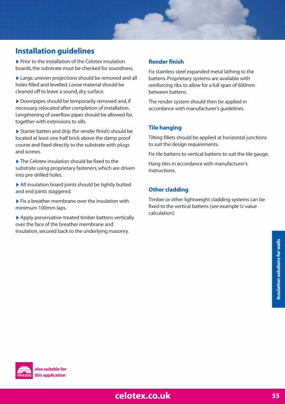
55celotex.co.uk
▶Prior to the installation of the Celotex insulationboards, the substrate must be checked for soundness.
▶Large, uneven projections should be removed and allholes filled and levelled. Loose material should becleaned off to leave a sound, dry surface.
▶Downpipes should be temporarily removed and, ifnecessary, relocated after completion of installation.Lengthening of overflow pipes should be allowed for,together with extensions to sills.
▶Starter batten and drip (for render finish) should belocated at least one half brick above the damp proofcourse and fixed directly to the substrate with plugsand screws.
▶The Celotex insulation should be fixed to thesubstrate using proprietary fasteners, which are driveninto pre-drilled holes.
▶All insulation board joints should be tightly buttedand end joints staggered.
▶Fix a breather membrane over the insulation withminimum 100mm laps.
▶Apply preservative-treated timber battens verticallyover the face of the breather membrane andinsulation, secured back to the underlying masonry.
Render finish
Fix stainless steel expanded metal lathing to thebattens. Proprietary systems are available withreinforcing ribs to allow for a full span of 600mmbetween battens.
The render system should then be applied inaccordance with manufacturer’s guidelines.
Tile hanging
Tilting fillets should be applied at horizontal junctionsto suit the design requirements.
Fix tile battens to vertical battens to suit the tile gauge.
Hang tiles in accordance with manufacturer’sinstructions.
Other cladding
Timber or other lightweight cladding systems can befixed to the vertical battens (see example U-valuecalculation).
Installation guidelines
Insu
lati
on s
olu
tion
s fo
r wal
ls
also suitable for this application

Use Celotex TB3000, Celotex GA3000 and Celotex XR3000 highperformance thermal insulation in timber frame wall liningapplications to minimise insulation thickness and give thefollowing benefits:
▶ Offers the thinnest solution available
▶ Provides reliable long term energy savings for buildings
▶ Low emissivity foil facers give improved thermal insulation within cavity air spaces
▶ Reduces thermal bridging through studs and rails, when used in a two-layer system.
▶ Provides cavity for services
Timber frame wall lining
Construction
Outside surface resistanceBrickCavity (low emissivity)PlywoodVariable layerCavity (low emissivity) between studs (15% brg)Polythene 1000 gauge, VCLPlasterboardInside surface resistance
Variable Layer
Celotex XR3000 between 175 stud (15% brg)Celotex XR3000 between 150 stud (15% brg)Celotex GA3000 between 125 stud (15% brg)Celotex GA3000 between 100 stud (15% brg)
Thickness(mm)
-103509
See below20/25
-12.5
-
Example U-value calculation: timber frame wall lining
56 T: 0901 996 0100*
Thickness(mm)
15013010080
U-value(W/m2K)
0.190.210.260.30
U-value
For U-values see variable layer list

▶Make sure all studs and rails are flush, with noprojections, and that services are correctly installed.
▶ Insert insulation into framing and push back toplywood sheathing. Fit services into cavity if required.
▶Use the Celotex Insulation Saw to cut the boards tofit tightly between all studs and rails.
▶For optimum thermal performance, the unprintedfoil surface should face the air cavity.
▶Use the Celotex Insulation Saw to cut the boards forinfill panels, using off-cuts where possible, making surethere are no gaps at wall abutments.
▶Ensure that the wall insulation is continuous with thefloor perimeter insulation.
▶A vapour control layer (VCL) should be installed overthe warm side of the studwork.
▶Fix plasterboard lining over the VCL usingplasterboard nails or screws.
NB: Some building insurance companies may requireadditional third party approval when using insulationin timber frame applications. Advice should be soughtfrom the relevant parties prior to specifying theinsulation required. Celotex insulation is covered byBBA certificate number 09/4667. Please note thatCelotex FR4000 is not covered by this certificate.
Installation guidelines
57celotex.co.uk
Insu
lati
on s
olu
tion
s fo
r wal
ls
also suitable for this application

Celotex offers two solutions for single timber frame wall liningapplications. The first utilises the low lambda values of CelotexGA3000 and Celotex XR3000 between the studs, followed by aninternal lining of Celotex TB3000 over the studs. This solutionprovides for the thinnest build-up with the better thermalinsulation.
The second option is to use mineral wool batts fittedbetween the studs, followed by an internal lining ofCelotex TB3000 over the studs. This solution gives athicker build-up but offers improved acousticinsulation.
Single timber frame wall lining and dormer cheeks
Construction
Outside surface resistanceWeatherboard - Tiles - Rendered - code 4 leadVentilated cavity batten air spaceBreather membranePlywoodCelotex between 100mm studs @ 400 ctrs (15% brg)Low E cavity between studs @ 400 ctrs (15% brg)Variable layer (for over studs)Polythene1000 gauge VCLPlasterboardInside surface resistance
Variable Layer
Celotex TB3000Celotex TB3000Celotex TB3000Celotex TB3000Celotex TB3000Celotex TB3000Celotex TB3000
Weatherboarding Tile Hung Rendered Lead CladThickness Thickness Thickness Thickness
(mm) (mm) (mm) (mm)- - - -
any any 20 1.825 n/a n/a n/a- - - -
12 12 12 12† GA3065 GA3060 GA3065 GA3065
35 40 35 35
See below See below See below See below- - - -
12.5 12.5 12.5 12.5- - - -
Thickness U-value U-value U-value U-value(mm) (W/m²K) (W/m²K) (W/m²K) (W/m²K)
45 0.20 0.21 0.21 0.2140 0.21 0.22 0.22 0.2235 0.23 0.23 0.23 0.2330 0.24 0.24 0.24 0.2425 0.25 0.26 0.26 0.2620 0.27 0.27 0.27 0.2712 0.30 0.30 0.30 0.30
GA = Celotex GA3000Low E = Low emissivity† When using lead clad, the plywood layer is moved to outside the ventilated batten airspace
Example U-value calculation: single timber frame wall (dormer cheeks)
58 T: 0901 996 0100*
Rendered

▶Make sure all studs and rails are flush, with noprojections, and that services are correctly installed.
▶Fit mineral wool batts or Celotex insulation tightly in-between all studs and push up to plywood sheathing.
▶For optimum thermal performance, the unprintedfoil surface should face the air cavity within thestudwork.
▶Use the Celotex Insulation Saw to cut boards for infillpanels, using off-cuts where possible, making surethere are no gaps at wall abutments.
▶ Install a second layer of Celotex insulation over the studs.
▶Tightly butt edges of boards together, making surethere are no gaps.
▶Temporarily secure the boards with clout nails at600mm centres. Mark stud lines on board surface asfixing guides for dry lining.
▶Always fix back to solid timber, both at stud lines andat top and bottom rails.
▶Ensure that all board surfaces are clean and freefrom dust and then apply Celotex Insulation Tape toseal all joints.
▶Seal around all penetrations for electrical outlets andswitch boxes.
▶Fix plasterboard lining over the Celotex insulationusing plasterboard nails or screws of appropriatelength and joint and skim to the desired finish.
▶No separate vapour check membrane is required inthis application. Celotex insulation acts as an effectiveinternal vapour control layer when all joints are sealed.
NB: Some building insurance companies may requireadditional third party approval when using insulationin timber frame applications. Advice should be soughtfrom the relevant parties prior to specifying theinsulation required. Celotex insulation is covered byBBA certificate number 09/4667. Please note thatCelotex FR4000 is not covered by this certificate.
Installation guidelines
59celotex.co.uk
Lead clad
Insu
lati
on s
olu
tion
s fo
r wal
ls
Weatherboarding
Tile hung
also suitable for this application

Use Celotex TB3000 or Celotex GA3000 high performanceinsulation in timber frame wall sheathing applications tominimise insulation thickness and give the followingbenefits:
▶ Eliminates thermal bridging of timber
▶ Provides reliable long term energy savings for buildings
▶ Low emissivity foil facers give improved thermal insulation performance within cavity air spaces
▶ Sheathing encapsulates the timber frame
▶ No threat of interstitial condensation
▶ Voids between studs free for services
Timber frame wall sheathing
Construction
Outside surface resistanceBrickCavity (low emissivity)Variable layerPlywoodCavity between studsPolythene 1000 gauge, VCLPlasterboardInside surface resistance
Variable Layer
Celotex GA3000Celotex GA3000Celotex GA3000Celotex GA3000Celotex GA3000Celotex GA3000Celotex TB3000Celotex TB3000Celotex TB3000
Thickness(mm)
-10350
See below9
89-
12.5-
Example U-value calculation: timber frame wall sheathing
60 T: 0901 996 0100*
Thickness(mm)
757065605550454035
U-value(W/m2K)
0.220.230.240.250.270.290.310.330.35
U-value
For U-values see variable layer list

▶Make sure all studs and rails are flush, with noprojections.
▶Fix sheet of Celotex GA3000 to the externalsheathing using galvanised clout nails at 400mmcentres in the centre of the board and at 300mmcentres around the perimeter.
▶For optimum thermal performance, the unprintedfoil surface should face the air cavity.
▶Care must be taken to align the fixings withunderlying studs, sole plates and head rails.
▶Tightly butt boards together and use off-cuts to fill inaround waist rails.
▶Brickwork should be tied back to the timber framingusing helical stainless steel wall ties, driven throughthe Celotex insulation into the studs.
▶ Insert ties approximately 10mm to 20mm above thebrick course so that a slight ‘crank’ can be applied. Thisensures that the tie slopes downward from thesheathing to the outer brickwork.
▶ Install horizontal cavity barriers, usually in the formof mineral wool ‘sausages’, to the surface of the Celotexinsulation board at all intermediate floors.
▶Apply vertical and horizontal cavity barriers in asimilar fashion around window and door openings.
NB: Some building insurance companies may requireadditional third party approval when using insulationin timber frame applications. Advice should be soughtfrom the relevant parties prior to specifying theinsulation required. Celotex insulation is covered byBBA certificate number 09/4667. Please note thatCelotex FR4000 is not covered by this certificate.
Gable walls
At gable walls, it is recommended that the insulationbe taken up to the underside of the roof verges.However, if a cold roof construction is intended, thecavity insulation should extend at least 250mm abovethe ceiling. The top edge of the insulation should beprotected with a cavity tray.
Other cladding
Tile hanging, render finish, weather boarding and othercladding types are all suitable for this application. Inthis situation, Celotex boards can be protected with abreather membrane. However, advice and informationon the installation of these cladding systems should besought from the manufacturer or provider of thecladding system.
Installation guidelines
61celotex.co.uk
Insu
lati
on s
olu
tion
s fo
r wal
ls
also suitable for this application

Use Celotex TB3000 or Celotex GA3000 high performance thermalinsulation in steel stud framed wall applications to minimiseinsulation thickness and give the following benefits:
▶ Ideal for lightweight, steel framed commercial and industrial buildings
▶ Provides reliable long term energy savingsfor buildings
▶ Low emissivity foil facer gives improved thermal insulation performance within cavity air spaces
▶ Rapid, accurate construction on-site
▶ Facilitates off-site fabrication of framed panels
▶ Warm frame construction eliminates thermal bridging through studs
▶ Thin overall construction depth
Steel stud framed walls
Construction
Outside surface resistanceBrickCavity (low emissivity)Variable layer (over studs)Cavity (low emissivity)Polythene 1000 gauge, VCLPlasterboardInside surface resistance
Variable Layer
Celotex GA3000Celotex GA3000Celotex GA3000Celotex GA3000Celotex GA3000Celotex GA3000Celotex TB3000Celotex TB3000Celotex TB3000Celotex TB3000
Thickness(mm)
-10350
See below100
-12.5
-
Example U-value calculation: steel stud framed wall
62 T: 0901 996 0100*
Thickness(mm)
75706560555045403530
U-value(W/m2K)
0.220.230.240.250.260.280.290.300.320.35
U-value
For U-values see variable layer list

▶ Install the steel stud framework in accordance withthe manufacturer’s instructions.
▶For optimum thermal performance, the unprintedfoil surface should face the air cavity.
▶ If necessary, trim the Celotex insulation boards to awidth and height to ensure that the edges are fullysupported by the frame studs or horizontal runners.
▶Trim boards to fit around window and dooropenings.
▶Place the boards directly against the external face ofthe steel frame and temporarily fix with suitable self-tapping screws and washers.
▶Adjacent boards must be tightly butted to minimiseheat loss.
▶Where the frame is to be faced with brickwork, placewall tie retaining channels over the boards at studpositions and fix through the insulation into the studswith fasteners as recommended by the channelmanufacturer.
▶Construct the brickwork facing incorporating twist-in ties at recommended intervals.
▶Fit cavity barriers between the brickwork and theface of the insulation board as required.
Other cladding
Tile hanging, render finish, weather boarding and othercladding types are all suitable for this application. Inthis situation, Celotex boards must always be protectedwith a breather membrane. However, advice andinformation on the installation of these claddingsystems should be sought from the manufacturer orprovider of the cladding system.
Installation guidelines
63celotex.co.uk
Insu
lati
on s
olu
tion
s fo
r wal
ls
also suitable for this application

Rainscreen cladding
64 T: 0901 996 0100*
Example U-value calculation: rainscreen cladding (up to 18 metres)
Use Celotex GA3000 or Celotex XR3000 highperformance thermal insulation in rainscreencladding applications up to 18 metres inheight to minimise insulation thicknessand give the following benefits:
▶ Ideal for use with masonry, steel or timber frame systems
▶ Provides reliable long term energy savings for buildings
▶ Low emissivity foil facers give improved thermal insulation values with cavity air spaces
▶ Suitable for use with many cladding type products
▶ Warm frame construction elimates thermal bridging through studs
Construction With rails or brackets With rails or bracketsbridging insulation over insulation
Thickness (mm) Thickness (mm)
Outside surface resistance - - Cladding - -Ventilated cavity between rails/brackets - -Breather membrane - -Variable layer See below See belowLow E cavity between steel frame 100 100Polythene 1000 gauge, VCL & airleakage barrier - -Plasterboard 12.5 12.5Plasterboard 12.5 12.5Inside surface resistance - -
Variable Layer Thickness U-value U-value (mm) W/m²K W/m²K
Celotex XR3000 110 0.25 0.19Celotex GA3000 100 0.26 0.20Celotex GA3000 90 0.28 0.22Celotex GA3000 80 0.30 0.24Celotex GA3000 75 0.31 0.25Celotex GA3000 70 0.33 0.27Celotex GA3000 65 0.34 0.28Celotex GA3000 60 n/a 0.30Celotex GA3000 55 n/a 0.32Celotex GA3000 50 n/a 0.34
Low E = Low emissivityVCL = Vapour control layer

65celotex.co.uk
Insu
lati
on s
olu
tion
s fo
r wal
ls
▶Please note that the use of Celotex GA3000 andCelotex XR3000 can only be used in rainscreencladding applications up to 18metres in height.
▶Tile hanging, weather boarding and other claddingtypes are all suitable for this application. Celotexboards must always be protected with a breathermembrane.
▶ In all instances, advice and information on theinstallation and fixings of these cladding systemsshould be sought directly from the manufacturer orprovider of the cladding system.
▶For optimum thermal performance, the unprintedfoil surface of the insulation should face the air cavitybetween the steel frame.
▶When cutting Celotex insulation boards on site, usethe Celotex Insulation Saw.
Installation guidelines
also suitable for this application

Concrete slab floorsThe specification of insulation for ground floors ismore complex than that for walls or roofs. This isbecause the mechanisms for heat flow areaffected by the ratio of surface area to perimeter.
Optimum positioning of the insulation within thefloor may depend on the positioning of theinsulation in the walls. For instance, wheninsulating dry lining is specified for the walls,over-slab insulation enables continuity of theinsulation to be achieved.
In over-slab installations, such as solid oversiteslabs and, more particularly, exposed solid slabs,use a vapour control membrane over theinsulation to eliminate any risk of condensationforming on the cold slab surface.
Beam and block floorsWith a beam and block floor, there is little choicebut to install the insulation over the floor beforescreeding. The ventilated air space beneath anysuspended floor can be very cold, so Celotexrecommends the application of a continuousvapour control membrane over the top of theinsulation, before screeding, to reduce the risk ofcondensation forming at the insulation/slabinterface. This also prevents screed migrationbetween the board joints, thus avoiding coldbridges.
Insulation solutions for floors
66 T: 0901 996 0100*

Suspended timber floorsWith a suspended timber floor, there is littlechoice but to install the insulation between thejoists, but the thermal bridges created by thejoists have to be considered.
Continuity of the insulation must be ensured bypacking the spaces between the external wallsand the joists with insulation.
The void below an insulated suspended timberfloor must be well ventilated. The insulation mustbe cut to fit tightly between the joists to preventheat loss.
Underfloor heatingUnderfloor heating is now recognised as one ofthe most efficient and cost-effective forms ofdomestic heating. For maximum efficiency itrequires effective insulation beneath the heatingelements to minimise heat loss downward intothe structure and to reflect the heat upwards intothe room.
Celotex insulation is the ideal solution.
Underfloor heating systems are used inapproximately 50% of all self-build homes andincreasingly in extension and conservatoryprojects. Many underfloor heating companiesalready make use of the high performancecharacteristics of Celotex insulation.
When extending a building, adding underfloorheating to the existing heating design can bringmajor benefits, especially in applications such asconservatories, where it is difficult to positionstandard radiators and an underfloor heatingsystem is possibly the only acceptable form ofheating.
67celotex.co.uk

Calculating the P/A ratio
U-value calculations
To calculate the minimum thickness of insulationneeded in a floor you should divide the exposedinternal perimeter by the internal area which will giveyou the P/A ratio.
Example 1 – detached dwelling
The overall internal dimensions of the dwelling are8.10m x 6.90m; these measurements ignore theinternal walls.
The exposed perimeter is 8.10m + 6.90m + 8.10m + 6.90m = 30.0m
The area is 8.10m x 6.90m = 55.89m
The P/A ratio is 30 / 55.89 = 0.54
For this example, with a concrete slab floor, you will require:
60mm of insulation to achieve 0.24 W/m2K
70mm of insulation to achieve 0.22 W/m2K
80mm of insulation to achieve 0.20 W/m2K
Example 2 – new extension
The overall internal dimensions of the dwelling are3.10m x 2.40m; these measurements ignore theinternal walls.
The exposed perimeter is 2.40m + 3.10m + 1.22m =6.72m
The area is 3.10m x 2.40m = 7.44m
The P/A ratio is 6.72 / 7.44 = 0.90
For this example, with a concrete slab floor, you will require:
70mm of insulation to achieve 0.24 W/m2K
80mm of insulation to achieve 0.22 W/m2K
90mm of insulation to achieve 0.20 W/m2K
68 T: 0901 996 0100*

Example 3 – dwelling with integralgarage
The overall internal dimensions of the dwellingare 8.50m x 6.90m; these measurements ignorethe internal walls.
The exposed perimeter is 8.50m + 6.90m +7.30m + 2.88m + 1.20m + 4.02m = 30.8m
The area is (8.50m x 6.90m) – (1.20m x 2.88m) =55.19m
The P/A ratio is 30.8 / 55.19 = 0.55
For this example, with a concrete slab floor, you will require:
60mm of insulation to achieve 0.24 W/m2K
70mm of insulation to achieve 0.22 W/m2K
80mm of insulation to achieve 0.20 W/m2K
69celotex.co.uk
Insu
lati
on s
olu
tion
s fo
r flo
ors

Concrete slab floors
U-value ready reckoner: ground floor – concrete slab
0.170.160.150.150.140.140.130.130.120.120.120.110.110.110.100.100.100.090.090.090.090.080.080.080.07
-0.250.240.220.210.200.200.190.180.170.160.160.150.150.140.140.130.120.120.110.110.110.100.090.08
-----
0.250.230.220.210.200.190.180.180.170.160.160.150.140.130.130.120.120.110.100.09
-------
0.240.230.220.210.200.190.180.180.170.160.150.140.130.130.120.120.110.09
--------
0.240.230.220.210.200.190.190.180.170.150.140.140.140.130.120.110.10
---------
0.240.230.220.210.200.190.180.170.160.150.140.140.130.120.120.10
---------
0.250.240.230.220.210.200.190.180.160.150.150.140.130.130.120.10
----------
0.240.230.220.210.200.200.180.170.150.150.140.140.130.120.10
----------
0.250.240.230.220.210.200.180.170.160.150.150.140.130.120.10
----------
0.250.240.230.220.210.200.180.170.160.150.150.140.130.120.10
Perimeter / Area ratio0.1 0.2 0.3 0.4 0.5 0.6 0.7 0.8 0.9 1.0
Based on 65mm screed & 20mm insulation as perimeter upstand
CelotexProduct
70 T: 0901 996 0100*
TB3012TB3020TB3025TB3030TB3035TB3040TB3045GA3050 / FF3050GA3055GA3060GA3065GA3070 / FF3070GA3075 / FF3075GA3080FF3085GA3090 / FF3090GA3100 / FF3100XR3110XR3120FF3125XR3130XR3140XR3150 / FF3150XR3165XR3200
Use Celotex TB3000, Celotex GA3000, Celotex XR3000and Celotex FF3000 high performance thermalinsulation in concrete slab floor applications tominimise insulation thickness and give thefollowing benefits:
▶ Conveniently sized boards for handling indoors
▶ Easy to cut boards to fit in most spaces
▶ Provides reliable long term energy savings for buildings
▶ Excellent dimensional stability
▶ No thermal bridging at floor edges
▶ Tightly butted joints for insulation continuity

Over slab installation guidelines
▶ Install a damp proof membrane over the top of, orbelow the slab. The damp proof membrane mustprovide continuity with the damp proof course in thesurrounding walls.
▶Level the surface of the slab; it should be smoothand free of projections.
▶ If required, use a thin layer of sand blinding on arough, tamped slab to ensure that the insulationboards are continuously supported.
▶Use the Celotex Insulation Saw to cut and fitinsulation upstand to floor perimeter, to meet aminimum R-value of 0.75m²K/W. i.e. Celotex TB3020.The upstand depth should be equal to the sum of theslab insulation and the screed thickness. The upstandthickness should not exceed the combined thicknessof the wall plaster and the skirting.
▶Lay the insulation boards directly onto the preparedslab with all joints tightly butted.
▶Lay a polythene vapour control layer (VCL) over theinsulation to minimise the risk of condensationforming at the insulation/slab interface and to preventliquid screed migration.
▶Apply a sand/cement or self levelling screed over theVCL and Celotex insulation boards to a minimumthickness of 65mm.
Use scaffold boards or other protection to preventwheelbarrows and other traffic damaging theinsulation.
These recommendations are suitable for normaldomestic floor loadings. If higher loadings are required,it may be necessary to increase the screed thicknessand provide reinforcement within the screed. Consult astructural engineer or a specialist flooring contractor.
Under slab installation guidelines
▶Level hardcore and blind with sand.
▶ Install damp proof membrane and lap into damp proof course.
▶Use the Celotex Insulation Saw to cut and fitinsulation, thickness to achieve required U-value.
▶Use the Celotex Insulation Saw to cut and fitinsulation upstand to floor perimeter, to meet aminimum R-value of 0.75m²K/W. i.e. Celotex TB3020.Height of insulation to coincide with required finishedfloor level.
▶Lay a polythene vapour control layer (VCL) over theinsulation to minimise the risk of condensationforming at the insulation/slab interface.
▶Lay concrete to required finished floor level andsmooth over with float finish.
Chipboard floor finish
A VCL should be laid over the Celotex insulation boardsand turned up 100mm at room perimeters, behind theskirting. It is recommended good practice that all jointsshould be lapped 150mm and sealed.
The chipboard must be minimum 18mm tongued andgrooved flooring grade type C4 to BS 5669. Lay thechipboard with staggered joints, glued with awoodworking adhesive.
Provide a 10mm - 12mm gap at all perimeters andabutments to allow for expansion. This can be achievedby the use of temporary wedges.
Where chipboard is butted together without atongued and grooved joint and all external doorways(for the width of the threshold), a treated timber battenmust be used in lieu of the insulation boards.
Installation guidelines
71celotex.co.uk
Insu
lati
on s
olu
tion
s fo
r flo
ors
also suitable for this application

Beam and block floors
72 T: 0901 996 0100*
U-value ready reckoner: ground floor – beam & block
0.230.210.200.200.190.180.170.170.160.160.150.150.140.140.130.130.120.120.110.110.110.100.100.090.08
-----
0.240.230.220.210.200.190.190.180.170.170.160.150.140.130.130.120.120.110.100.09
-------
0.250.240.220.210.200.200.190.180.170.160.150.140.140.130.130.120.110.09
--------
0.250.240.230.220.210.200.190.180.170.160.150.140.140.130.120.110.10
---------
0.250.240.230.210.210.200.190.170.160.150.150.140.130.130.120.10
----------
0.240.230.220.210.200.190.180.160.150.150.140.140.130.120.10
----------
0.250.240.220.210.200.200.180.170.160.150.150.140.130.120.10
----------
0.250.240.230.220.210.200.180.170.160.150.150.140.130.120.10
-----------
0.240.230.220.210.200.180.170.160.150.150.140.130.120.10
-----------
0.240.230.220.210.190.170.170.160.150.150.140.130.120.10
Perimeter / Area ratio0.1 0.2 0.3 0.4 0.5 0.6 0.7 0.8 0.9 1.0
Based on 65mm screed & 20mm insulation as perimeter upstand
CelotexProduct
TB3012TB3020TB3025TB3030TB3035TB3040TB3045GA3050 / FF3050GA3055GA3060GA3065GA3070 / FF3070GA3075 / FF3075GA3080FF3085GA3090 / FF3090GA3100 / FF3100XR3110XR3120FF3125XR3130XR3140XR3150 / FF3150XR3165XR3200
Use Celotex TB3000, Celotex GA3000, Celotex XR3000and Celotex FF3000 high performance thermal insulationin beam and block floors to minimise insulationthickness and give the following benefits:
▶ Conveniently sized boards for handling indoors
▶ Easy to cut boards to fit in most spaces
▶ Provide reliable long term energy savings for buildings
▶ Excellent dimensional stability
▶ Optimised continuity with wall insulation
▶ Tightly butted joints for insulation continuity
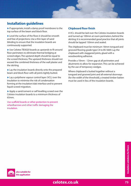
▶ If appropriate, install a damp proof membrane to thetop surface of the beam and block floor.
▶Level the surface of the floor; it should be smoothand free of projections. Use a thin layer of sandblinding to ensure that the insulation boards arecontinuously supported.
▶Use Celotex TB3020 boards as upstands to fit aroundfloor perimeters to eliminate thermal bridging atscreed edges. The upstand depth should be equal tothe screed thickness. The upstand thickness should notexceed the combined thickness of the wall plaster andthe skirting.
▶Lay the insulation boards directly onto the preparedbeam and block floor with all joints tightly butted.
▶Lay a polythene vapour control layer (VCL) over theinsulation to minimise the risk of condensationforming at the insulation/slab interface and to preventliquid screed migration.
▶Apply a sand/cement or self levelling screed over theCelotex insulation boards to a minimum thickness of65mm.
Use scaffold boards or other protection to preventwheelbarrows and other traffic damaging theinsulation.
Chipboard floor finish
A VCL should be laid over the Celotex insulation boardsand turned up 100mm at room perimeters, behind theskirting. It is recommended good practice that all jointsshould be lapped 150mm and sealed.
The chipboard must be minimum 18mm tongued andgrooved flooring grade type C4 to BS 5669. Lay thechipboard with staggered joints, glued with awoodworking adhesive.
Provide a 10mm - 12mm gap at all perimeters andabutments to allow for expansion. This can be achievedby the use of temporary wedges.
Where chipboard is butted together without atongued and grooved joint and all external doorways(for the width of the threshold), a treated timber battenmust be used in lieu of the insulation boards.
Installation guidelines
73celotex.co.uk
Insu
lati
on s
olu
tion
s fo
r flo
ors
also suitable for this application

Use Celotex TB3000, Celotex GA3000 and Celotex XR3000 highperformance thermal insulation in suspended timber floors tominimise insulation thickness and give the following benefits:
▶ Quick and easy to install insulation between joists in one layer
▶ Boards permanently retained by patented Celotex insulation clip
▶ Minimise air leakage by friction fitting the insulation
▶ Provides reliable long term energy savings for buildings
▶ Low emissivity foil facers give improved thermal insulation performance within air spaces
▶ Minimal load added to structure due to light-weight boards
Suspended timber floors
U-value ready reckoner: ground floor – suspended timber
0.240.220.210.210.200.200.190.180.180.180.170.170.160.160.150.150.140.130.130.130.130.120.11
-------
0.250.240.230.230.220.210.210.190.180.170.170.160.160.150.140.13
-----------
0.250.240.230.220.200.190.180.180.170.160.150.14
-------------
0.250.230.220.200.190.190.180.170.160.14
--------------
0.240.220.210.200.190.180.180.170.14
--------------
0.250.230.220.200.200.190.180.170.15
--------------
0.250.230.220.210.200.190.180.170.15
---------------
0.240.220.210.200.200.180.170.15
---------------
0.240.230.210.210.200.190.170.15
---------------
0.240.230.210.210.200.190.170.15
Perimeter / Area ratioCelotexProduct 0.1 0.2 0.3 0.4 0.5 0.6 0.7 0.8 0.9 1.0
Based on timbers joists @ 400 Ctrs
74 T: 0901 996 0100*
TB3012TB3020TB3025TB3030TB3035TB3040TB3045GA3050GA3055GA3060GA3065GA3070GA3075GA3080GA3090GA3100XR3110XR3120XR3130XR3140XR3150XR3165XR3200

▶ Install joists in the conventional manner, with solid ordiagonal strut bracing as necessary. (NB: diagonalbracing may lead to thermal bridging)
▶The patented Celotex Insulation Clip is designed toallow insulation boards to be installed between timberjoists quickly and without nails or screws.
▶Either fit the clips at one metre maximum centresalong the edge of the insulation (as described on page15) or fix battens to the sides of the joists to supportthe insulation.
▶Use the Celotex Insulation Saw to cut the boards to achieve a tight fit, then push the boards firmly downbetween the joists. The insulation clip will ensure afriction fit.
▶ Insulate gaps between the joists and walls to preventthermal bridging.
▶ Install either chipboard or softwood floor boardingdirectly onto the joists.
▶Ensure that the void below the insulation isventilated.
Exposed floors (other than ground) ▶For exposed or semi-exposed floors, e.g. garage orcar port ceilings, it may be easier to insulate frombelow.
▶Fix Celotex insulation boards directly to theunderside of the joists with galvanised clout nails at400mm maximum centres. Finish with an appropriatefire protection board fixed to the soffit.
▶An additional layer of 100mm mineral woolinsulation can be installed between the joists,supported by the soffit lining, to provide acousticinsulation.
Installation guidelines
75celotex.co.uk
Insu
lati
on s
olu
tion
s fo
r flo
ors
also suitable for this application
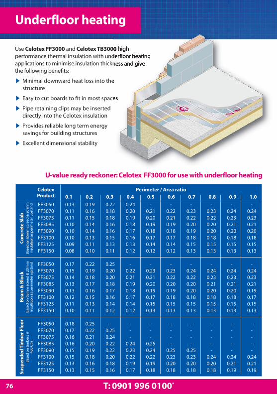
Use Celotex FF3000 and Celotex TB3000 highperformance thermal insulation with underfloor heatingapplications to minimise insulation thickness and givethe following benefits:
▶ Minimal downward heat loss into the structure
▶ Easy to cut boards to fit in most spaces
▶ Pipe retaining clips may be inserted directly into the Celotex insulation
▶ Provides reliable long term energy savings for building structures
▶ Excellent dimensional stability
Underfloor heating
U-value ready reckoner: Celotex FF3000 for use with underfloor heating
FF3050FF3070FF3075FF3085FF3090FF3100FF3125FF3150
FF3050FF3070FF3075FF3085FF3090FF3100FF3125FF3150
FF3050FF3070FF3075FF3085FF3090FF3100FF3125FF3150
0.130.110.110.100.100.100.090.08
0.170.150.140.130.130.120.110.10
0.180.170.160.160.150.150.130.13
0.190.160.150.140.140.130.110.10
0.220.190.180.170.160.150.130.11
0.250.220.210.200.190.180.160.15
0.220.180.180.160.160.150.130.11
0.250.200.200.180.170.160.140.12
-0.250.240.220.220.200.180.16
0.240.200.190.180.170.160.130.12
-0.220.210.190.180.170.140.12
---
0.240.230.220.190.17
-0.210.200.190.180.170.140.12
-0.230.210.200.190.170.150.13
---
0.250.240.220.190.18
-0.220.210.190.180.170.140.12
-0.230.220.200.190.180.150.13
----
0.250.230.200.18
-0.230.220.200.190.180.150.13
-0.240.220.200.200.180.150.13
----
0.250.230.200.18
-0.230.220.200.200.180.150.13
-0.240.230.210.200.180.150.13
-----
0.240.200.18
-0.240.230.210.200.180.150.13
-0.240.230.210.200.180.150.13
-----
0.240.210.19
-0.240.230.210.200.180.150.13
-0.240.230.210.190.170.150.13
-----
0.240.210.19
Perimeter / Area ratioCelotexProduct 0.1 0.2 0.3 0.4 0.5 0.6 0.7 0.8 0.9 1.0
Susp
end
ed T
imb
er F
loo
rBa
sed
on
timb
ers
@
400
Ctr
s
Bea
m &
Blo
ckBa
sed
on
65m
m s
cree
d &
20
mm
insu
latio
n as
per
imet
er u
pst
and
Co
ncr
ete
Slab
Base
d o
n 65
mm
scr
eed
& 2
0 m
min
sula
tion
as p
erim
eter
up
stan
d
76 T: 0901 996 0100*

Installation guidelines
77celotex.co.uk
Pre-installation guidelines for concrete slabfloor applications only
▶ Install a damp proof membrane (DPM) below theslab or apply a liquid waterproofing membrane to thetop surface of the slab.
▶The DPM must provide continuity with the dampproof course in the surrounding walls.
▶Level the surface of the slab; it should be smoothand free of projections.
▶Use a thin layer of sand blinding on a rough tampedslab to ensure that the insulation boards arecontinuously supported.
Use scaffold boards or other protection to preventwheelbarrows and other traffic damaging theinsulation.
Installation guidelines for concrete slab andbeam & block floor applications
▶Use Celotex TB3000 boards as upstands to fit around floor perimeters to eliminate thermalbridging at screed edges. The upstand depth should be equal to the sum of the slab insulation and thescreed thickness. The upstand thickness should notexceed the combined thicknesses of the wall plasterand the skirting.
▶Lay the insulation boards directly into the preparedslab/beam and block with all joints tightly butted.
▶ Install a polythene membrane over the insulation.
▶Lay a proprietary underfloor heating system,generally comprising pipework in coils. Pipe retainingclips may be inserted directly into the Celotexinsulation.
▶Apply the screed over the Celotex insulation boardsto a thickness recommended by the manufacturer ofthe underfloor heating system (normally 75mm).
▶Compact the screed solidly when laid.
▶Allow the screed to dry thoroughly before animpermeable surface, such as a vinyl floor finish, isapplied. (Consult a specialist flooring contractor).
These recommendations are suitable for normaldomestic floor loadings. If higher loadings are requiredit may be necessary to increase the screed thicknessand provide reinforcement within the screed. Consult astructural engineer or specialist flooring contractor.
Installation guidelines for suspended timberfloor applications
▶ Install joists in the conventional manner, with solid ordiagonal strut bracing as necessary. (NB: diagonalbracing may lead to thermal bridging).
▶Fix battens to the sides of the joists to support theinsulation and to form a cavity for the underfloorheating, between the insulation and floor boards.
▶Use the Celotex Insulation Saw to cut the CelotexFF3000 insulation to achieve a tight fit, then push theboards firmly down between the joists.
▶ Insulate the gaps between thejoists and wall to preventthermal bridging.
▶Lay a proprietaryunderfloor heatingsystem within thecavity, generallycomprisingpipework in coils,to themanufacturer’sguidelines.
▶ Install either chipboardor soft wood floor boarding directlyonto the joists.
Insu
lati
on s
olu
tion
s fo
r flo
ors

Use Celotex FR4000 premium performance PIRinsulation in concrete soffit floor applications tominimise insulation thickness and give the followingbenefits:
▶ A thermal conductivity of 0.022W/mKoffering enhanced thermal performance andeven lower U-values
▶ Class O fire performance throughout theentire product
▶ Excellent sustainability credentialsincluding an ‘A’ rating in the 2008 GreenGuide, low GWP and zero ODP
▶ Provides reliable long term energy savingsfor buildings
▶ Additional protection possible via a layer ofcementitious board
Concrete soffit floors
78 T: 0901 996 0100*
Example U-value calculation: concrete soffit floors
Construction Exposed insulation Protected insulationThickness (mm) Thickness (mm)
Inside surface resistance - - Concrete 150 150Variable layer See below See belowLow E cavity (25x50mm timberbattens @ 600ctrs) n/a 25Cementitious board n/a 12.5 Outside surface resistance - -
Variable Layer Thickness U-value U-value (mm) W/m²K W/m²K
Celotex FR4000 200 0.12 0.11
Celotex FR4000 165 0.14 0.12
Celotex FR4000 150 0.15 0.13
Celotex FR4000 140 0.16 0.14
Celotex FR4000 130 0.17 0.15
Celotex FR4000 120 0.18 0.16
Celotex FR4000 110 0.20 0.17
Celotex FR4000 100 0.22 0.19
Celotex FR4000 90 0.24 0.20
Celotex FR4000 80 0.26 0.21
Celotex FR4000 75 n/a 0.22
Celotex FR4000 70 n/a 0.24
Low E = Low emissivity

Installation guidelines for direct fixing toconcrete soffit
▶ It is recommended that the Celotex insulationboards are installed with joints break-bonded.
▶Directly fix Celotex insulation to concrete soffit.Fixings should be evenly laid out with a minimum of 11 fixings per 1200mm x 2400mm board.
▶Fixings should be installed between 50mm - 150mmfrom the edge and corners of the board. Suitablefixings should comprise a screw type suitable for theconcrete deck into which it is being driven, combinedwith a circular or rectangular plate washer having asurface area of not less than 45cm². Advice on suitablefixings should be sought directly from the fixingmanufacturer.
Please note that the foil facer of the Celotex insulationis not intended to provide a decorative finish. Whereadditional protection is required please follow theinstallation guidelines shown below.
Installation guidelines using cementitiousboard for additional protection
▶ It is recommended that the Celotex insulationboards are laid with joints break-bonded.
▶Directly fix Celotex insulation and 25mm x 50mmtimber fixing battens to concrete soffit. The timberbattens should be fixed underneath the layer ofCelotex insulation. Ensure that the timber fixingbattens are secured at 600mm centres and that thefixings through into the concrete soffit are also at600mm centres.
▶Fixings should be installed between 50mm - 150mmfrom the edge and corners of the board. Suitablefixings should comprise a screw type suitable for theconcrete deck into which it is being driven. Advice onsuitable fixings should be sought directly from thefixing manufacturer.
▶To provide additional protection, fix a layer ofcementitious board to the timber battens usingsuitable fixings. Advice on suitable fixings should besought directly from the fixing manufacturer.
Installation guidelines
79celotex.co.uk
Insu
lati
on s
olu
tion
s fo
r flo
ors

Garage conversions
Upgrading existing floors: U-valuerequirement is 0.25 W/m²KWhen insulating floors, either with 65mm screed andCelotex TB3020 edge insulation, or with an 18mmchipboard finish, a 1200 gauge damp proof membrane(DPM) must be laid below the Celotex. A minimum 500gauge polythene layer must also be installed on top ofthe insulation to prevent screed migration and anyreaction between the aluminium facer and the screed.
All floors depend on the ratio of the length of theexposed perimeter of the floor divided by its area. The exposed perimeter is measured internally and isthe length of any walls which are not heated on theother side.
For the following P/A ratios, use the following Celotexproducts:
P/A ratio = 0.70 - 1.2, use Celotex GA3070P/A ratio = 0.45 - 0.69, use Celotex GA3060P/A ratio = 0.33 - 0.44, use Celotex GA3050P/A ratio = <0.32, use Celotex TB3040
NB: If using an underfloor heating system, ask us aboutCelotex FF3000.
Upgrading existing internal walls: U-value requirement is 0.35 W/m²KWhen insulating a 215mm brick wall, fix CelotexTB3040 to the wall by over battening with 25mm x50mm battens at 600mm centres. This is fixed throughthe battens and Celotex TB3040 into the wall usingproprietary fixings. The joints of the insulation are thentaped using Celotex Insulation Tape and the perimeteredges sealed with mastic, thereby providing a vapourcontrol layer (VCL). Finally, fix 12.5mm plasterboard tothe battens. The above installation will provide a U-value of 0.35 W/m2K.
When insulating a 250mm uninsulated cavity wall,follow the same procedure and thickness of insulationto achieve a U-value of 0.34 W/m2K.
When insulating a 250mm insulated cavity wall, followthe same procedure but use Celotex TB3030 to achievea U-value of 0.35 W/m2K
When insulating a 103mm brick wall, first fix a breathermembrane against the wall then follow the sameprocedure as mentioned previously, but use CelotexTB3045 to achieve a U-value of 0.35 W/m2K.
Upgrading existing or constructingnew sloping ceilings: U-valuerequirement is 0.20 W/m²KWhen insulating 100mm x 50mm rafters at 400mmcentres, use Celotex GA3050 between the rafters, thenfix Celotex GA3060 beneath the rafters. The joints ofthe insulation beneath the rafters are then taped usingCelotex Insulation Tape and the perimeter edges aresealed with mastic to provide a vapour control layer(VCL). A 25mm batten is then installed on the line ofthe rafter. Finally, fix the 12.5mm plasterboard throughthe battens.
When insulating 125mm x 50mm rafters at 400mmcentres, use the same fixing method as above but useCelotex GA3075 between the rafters and CelotexTB3045 beneath the rafters. In this instance no battenis required.
When insulating 150mm x 50mm rafters at 400mmcentres, use Celotex GA3100 between the rafters andCelotex TB3035 beneath the rafters. In this instance nobatten is required.
In all of the above solutions you must ventilate the50mm cavity above the insulation.
U-value achieved is 0.20 W/m2K in each case.
80 T: 0901 996 0100*
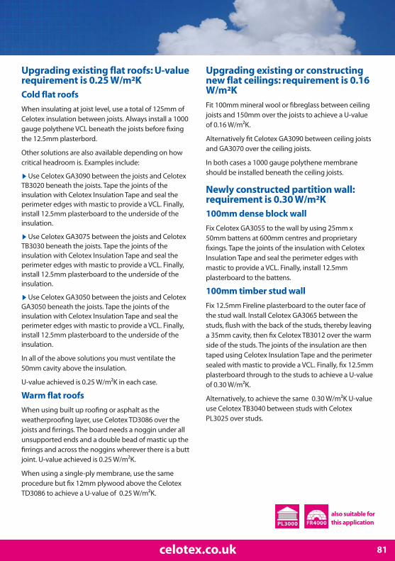
81celotex.co.uk
Upgrading existing flat roofs: U-valuerequirement is 0.25 W/m²KCold flat roofs
When insulating at joist level, use a total of 125mm ofCelotex insulation between joists. Always install a 1000gauge polythene VCL beneath the joists before fixingthe 12.5mm plasterbord.
Other solutions are also available depending on howcritical headroom is. Examples include:
▶Use Celotex GA3090 between the joists and CelotexTB3020 beneath the joists. Tape the joints of theinsulation with Celotex Insulation Tape and seal theperimeter edges with mastic to provide a VCL. Finally,install 12.5mm plasterboard to the underside of theinsulation.
▶Use Celotex GA3075 between the joists and CelotexTB3030 beneath the joists. Tape the joints of theinsulation with Celotex Insulation Tape and seal theperimeter edges with mastic to provide a VCL. Finally,install 12.5mm plasterboard to the underside of theinsulation.
▶Use Celotex GA3050 between the joists and CelotexGA3050 beneath the joists. Tape the joints of theinsulation with Celotex Insulation Tape and seal theperimeter edges with mastic to provide a VCL. Finally,install 12.5mm plasterboard to the underside of theinsulation.
In all of the above solutions you must ventilate the50mm cavity above the insulation.
U-value achieved is 0.25 W/m2K in each case.
Warm flat roofs
When using built up roofing or asphalt as theweatherproofing layer, use Celotex TD3086 over thejoists and firrings. The board needs a noggin under allunsupported ends and a double bead of mastic up thefirrings and across the noggins wherever there is a buttjoint. U-value achieved is 0.25 W/m2K.
When using a single-ply membrane, use the sameprocedure but fix 12mm plywood above the CelotexTD3086 to achieve a U-value of 0.25 W/m2K.
Upgrading existing or constructingnew flat ceilings: requirement is 0.16W/m²KFit 100mm mineral wool or fibreglass between ceilingjoists and 150mm over the joists to achieve a U-valueof 0.16 W/m2K.
Alternatively fit Celotex GA3090 between ceiling joistsand GA3070 over the ceiling joists.
In both cases a 1000 gauge polythene membraneshould be installed beneath the ceiling joists.
Newly constructed partition wall:requirement is 0.30 W/m²K100mm dense block wall
Fix Celotex GA3055 to the wall by using 25mm x50mm battens at 600mm centres and proprietaryfixings. Tape the joints of the insulation with CelotexInsulation Tape and seal the perimeter edges withmastic to provide a VCL. Finally, install 12.5mmplasterboard to the battens.
100mm timber stud wall
Fix 12.5mm Fireline plasterboard to the outer face ofthe stud wall. Install Celotex GA3065 between thestuds, flush with the back of the studs, thereby leavinga 35mm cavity, then fix Celotex TB3012 over the warmside of the studs. The joints of the insulation are thentaped using Celotex Insulation Tape and the perimetersealed with mastic to provide a VCL. Finally, fix 12.5mmplasterboard through to the studs to achieve a U-valueof 0.30 W/m2K.
Alternatively, to achieve the same 0.30 W/m2K U-valueuse Celotex TB3040 between studs with CelotexPL3025 over studs.
also suitable for this application
Loft conversions
Upgrading existing or constructingnew sloping ceilings: U-valuerequirement is 0.20 W/m²KWhen insulating 100mm x 50mm rafters at 400mmcentres, use Celotex GA3050 between the rafters, thenfix Celotex GA3060 beneath the rafters. The joints of theinsulation beneath the rafters are then taped usingCelotex Insulation Tape and the perimeter edges sealedwith mastic to provide a vapour control layer (VCL). A25mm batten is then installed on the line of the rafter,on to which the 12.5mm plasterboard is then fixedthrough to the battens.
When insulating using 125mm x 50mm rafters at400mm centres, use the same fixing method as above,but use Celotex GA3075 between the rafters andCelotex TB3045 beneath the rafters.
When insulating 150mm x 50mm rafters at 400mmcentres, use Celotex GA3100 between the rafters andCelotex TB3035 beneath the rafters. In this instance, nobatten is required.
In all of the above solutions you must ventilate the50mm cavity above the insulation.
U-value achieved is 0.20 W/m²K in each case.
Constructing new flat roofs: U-valuerequirement is 0.20 W/m²KWarm flat roofs
When using built up roofing or asphalt as theweatherproofing layer use Celotex TD3116 over thejoists and firrings. The board needs a noggin under allunsupported ends and a double bead of mastic up thefirrings and across the noggins wherever there is a buttjoint. U-value achieved is 0.20 W/m²K.
When using a single-ply membrane, use the sameprocedure but fix 12mm plywood above the CelotexTD3116. This will achieve a U-value of 0.20 W/m²K.
Cold flat roofs
When insulating at joist level, use a total of 165mm ofCelotex insulation to build up a 165mm thicknessbetween joists. Always install a 1000 gauge polytheneVCL below the joists before fixing the 12.5mmplasterboard.
Other solutions are also available, depending uponhow critical internal headroom is. Examples include:
▶ Use Celotex XR3120 between joists and CelotexTB3025 beneath the joists. Tape the joints of theCelotex with Celotex Insulation Tape and seal theperimeter edges with mastic to provide a VCL. Nail orscrew plasterboard or other lining through theinsulation to the rafter, ensuring that the length of thefasteners is adequate to secure the plasterboard lining.
▶ Use Celotex GA3100 between the joists and CelotexTB3035 beneath the joists. Tape the joints of the Celotex with Celotex Insulation Tape and seal theperimeter edges with mastic to provide a VCL. Nail orscrew plasterboard or other lining through theinsulation to the rafter, ensuring that the length of the fasteners is adequate to secure the plasterboard lining.
▶ Use Celotex GA3075 between the joists and CelotexGA3050 beneath the joists. Tape the joints of theCelotex with Celotex Insulation Tape and seal theperimeter edges with mastic to provide a VCL. Nail orscrew plasterboard or other lining through theinsulation to the rafter, ensuring that the length of thefasteners is adequate to secure the plasterboard lining.
▶ Use Celotex GA3050 between the joists and CelotexGA3060 beneath the joists. Tape the joints of theCelotex with Celotex Insulation Tape and seal theperimeter edges with mastic to provide a VCL. Finally,install a 25mm batten beneath the insulation and fix12.5mm plasterboard to the batten.
In all of the above solutions, you must ventilate the50mm cavity above the insulation.
U-value achieved is 0.20 W/m²K in each case.
82 T: 0901 996 0100*

Upgrading existing gable walls andparty walls: U-value requirement is0.35 W/m²KWhen insulating a 215mm brick wall, fix Celotex TB3040to the wall by over battening with 25mm x 50mmbattens at 600mm centres. This is fixed through thebattens and Celotex TB3040 into the wall usingproprietary fixings. The joints of the Celotex are thentaped using Celotex Insulation Tape and the perimeteredges sealed with mastic to provide a VCL. Finally, fix12.5mm plasterboard through the studs to achieve a U-value of 0.35 W/m²K.
When insulating a 250mm uninsulated cavity wall, usethe same procedure and thickness of insulation toachieve a U-value of 0.33 W/m²K.
Constructing new attic walls: U-valuerequirement is 0.30 W/m²KWhen insulating a 100mm stud wall, install CelotexGA3065 between the studs, flush with the back of thestuds, thereby leaving a 35mm cavity, then fix CelotexTB3012 over the inside face of the studs. The joints ofthe insulation are then taped using Celotex InsulationTape and the perimeter sealed with mastic to provide aVCL. Finally, fix 12.5mm plasterboard through to thestuds to achieve a U-value of 0.30 W/m²K.
When insulating 125mm studs use Celotex GA3090between the studs, again leaving a 35mm cavitybetween the studs, then fix a 1000 gauge polythenemembrane over the studs and seal the perimeter withmastic to provide a VCL. Finally, fix 12.5mmplasterboard through the studs to achieve a U-value of0.30 W/m²K.
For 150mm studs, use exactly the same procedure toachieve a U-value of 0.29 W/m²K.
Constructing new dormer face and cheeks: U-value requirement is 0.30 W/m²KExternal tiling
In the case of 100mm studs with external tiling hung overa breather membrane on top of 12mm sheathing ply,use Celotex GA3060 between the studs, leaving a 40mmcavity between the studs. Then, over the inside face of thestuds fix Celotex TB3012, taping the joints using CelotexInsulation Tape and the perimeter edges sealed withmastic to provide a VCL. Finally, fix 12.5mm plasterboardthrough the studs to achieve a U-value of 0.30 W/m²K.
External render
In the case of 100mm studs with an external renderfinish, use the same procedure with Celotex GA3065between and Celotex TB3012 over the face to achieve aU-value of 0.30 W/m²K.
External weatherboarding
In the case of 100mm studs with externalweatherboarding fixed over battens and a breathermembrane to create a ventilated space over a 12mmsheathing ply, install Celotex GA3065 between thestuds. Then over the inside face of the studs fix CelotexTB3012, taping the joints using Celotex Insulation Tapeand the perimeter edges sealed with mastic to providea VCL. Finally, fix 12.5mm plasterboard through thestuds to achieve a U-value of 0.30 W/m²K.
Alternatively use Celotex TB3045 between the studsand PL3025 over the studs.
Upgrading existing or constructingnew flat ceilings: U-valuerequirement is 0.16 W/m²KFit Celotex GA3090 between ceiling joists and CelotexGA3070 over the ceiling joists to achieve a U-value of0.16 W/m²K.
Alternatively, fit 100mm mineral wool or fibreglassbetween ceiling joists and Celotex XR3150 over the joists.
In both cases a 1000 gauge polythene membraneshould be installed beneath the ceiling joists prior tofixing the plasterboard.
83celotex.co.uk
also suitable for this application

Environmental & Sustainability Statement
84 T: 0901 996 0100*
Operating within the construction sector andspecialising in insulation products we are acutelyaware of the energy efficiency and carbonemission impact of our industry and activities. Wecontinue to concentrate on energy efficiency andreducing our CO2 emissions through our ownactivities and working in conjunction with ourtrade partners and the supply chain process.
The use and specification of Celotex products will offer:
▶ The lowest environmental impact of any PIRmanufacturer.
▶ An Approved Environmental Profile from BRE Global featuring the lowest Ecopoint score perm² of any PIR insulation product.
▶ An A+ Rating in the 2008 Green Guide toSpecification.*
▶ Credits in the Energy, Materials & Pollutioncategories of the Code for SustainableHomes/BREEAM.
▶ The broadest range of PIR product thicknesseshelping achieve maximum U-values, minimise airleakage and overcome thermal bridging.
▶ Products with a low GWP† and zero ODP rating.
▶ The most sustainable PIR solution.
* Does not refer to all Celotex products † Excludes Celotex LG3000
Celotex will at all times pursue strategies withinits operations, product development andcommercial activities which adhere to theprinciples of sustainability. Specific attention willbe paid to:
▶ Compliance with future environmentallegislation and approved codes of practice.
▶ Minimising environmentally harmfulemissions and noise from our manufacturingprocesses.
▶ Waste management initiatives which continueto ensure minimum levels of waste from ourproduction and packaging.
▶ Developing strategies to enable theCompany’s products to be used and re-used in anenvironmentally sensitive way, or recycled at theend of their useful life.
▶ Liaising with employees and the localcommunity to raise awareness and encourageparticipation in environmental matters,specifically in waste reduction, recycling andreducing CO2 emissions.
▶ Optimising the use of energy in allmanufacturing and business activities in order toreduce related carbon dioxide emissions.
For further information on Celotex andSustainability, including a downloadable copy ofour ‘Sustainability and The Road to Zero Carbon’brochure, please visit the ‘Sustainability’ sectionof our website at celotex.co.uk. Alternatively,please contact the Celotex Technical Centre on 0901 996 0100* to find out how we can helpreduce your carbon emissions and achieveregulatory compliance.

Waste managementCelotex continually monitors the levels of wastefrom its activities and drives and implementsprocedures which help reduce the amount ofwaste produced. The company ensures that allemployees are aware of the importance ofreducing waste in all its activities.
A company suggestion scheme allows allemployees to suggest methods of reducingwaste both in production and non-productionareas. Thicker boards are packed via a differentpacking system, reducing the level of wastematerial by introducing a returnable elementthat can consistently be reused. Our currentmethod of cardboard packaging has seen a 30%reduction in the quantity of cardboard usedcompared to the previous method.
Recycling
Waste PIR is inert and land fill safe with no knowneffect on ground water. Glass-fibre used as corereinforcement in some of our boards, is made upalmost entirely from recycled waste glass. Themajority of our boards are packed in glued andstapled cardboard boards. This element isrecyclable and means other methods ofpackaging such as shrink wrapping are avoided.
General informationStorage and handling
▶ Celotex insulation boards should be storeddry, flat and clear of the ground. Only as muchmaterial as can be installed during a singleworking period should be removed from storageat any one time. If boards are stored undertarpaulins, care should be taken to prevent ropedamage to the boards.
▶ Care should also be taken to ensure that packsare not dropped onto corners or edges.
▶ Where possible, cut the product using theCelotex Insulation Saw to minimise dust creation.
▶ When cutting Celotex insulation, dustextraction equipment, eye protection and facemasks must be provided. Dust or particles in theeyes should be washed out with liberal quantitiesof water.
▶ Aluminium foil edges may be sharp. Avoidsliding bare hands along board edges.
Health and safety
Full guidance on the appropriate measures to betaken by an employer in accordance with theCOSHH Regulations is provided in the CelotexHealth and Safety Data Sheet which can bedownloaded from our website.
Quality assurance
Product and application development is priorityat Celotex, with a focus onhigh performance,durability and usability. Thisis achieved through aquality managementsystem which has been fullyassessed and certified as meeting therequirements of BS EN ISO 9001.
Other products
Celotex offers a comprehensive range ofinsulation products for floor, wall and roofapplications as well as a complementary range ofaccessory products to make the installation ofCelotex even easier. For information please seepage 14, visit celotex.co.uk or contact our SalesDepartment.
Ancillary components
A list of suppliers of ancillary components for thefixing and sealing of Celotex products is availablefrom celotex.co.uk or by contacting the CelotexTechnical Centre.
85celotex.co.uk

Notes
86 T: 0901 996 0100*
Characteristics, properties or performance of materials described herein are derived from data obtained under controlled test conditions. CelotexLimited makes no warranty, express or implied as to their characteristics under any variations from such conditions in actual constructions.All products are supplied subject to our standard terms and conditions of sale, a copy of which is available on request.Typical details shown in this brochure are provided for guidance only and are not to scale. Celotex Limited makes no warranty, express or implied asto the suitability of such details for any particular project. It is the responsibility of the designer to ensure that any design or construction details usedare suitable for the project, having due regard to the environmental and structural factors which are beyond the control of Celotex Limited.Notwithstanding the foregoing, nothing herein stated shall exclude or restrict:1. The liability of Celotex Limited in respect of death or personal injury pursuant to the relevant provisions of the Unfair Contract Terms Act 1977, or2. The liability of Celotex Limited in respect of any damage caused by a defect to the extent that such comes within the relevant provisions of the
Consumer Protection Act 1987.
* Calls are charged at 30p per minute from a BT landline and lines are open Monday – Friday from 8:00am – 5:15pm.Details and pricing are correct at date of publication – September 2009.

87
Celotex: Offering a top class solution.
Celotex has achieved an A+ rating in the 2008 Green Guide and offersthe best Ecopoint score of any PIR insulation through its BRE ApprovedEnvironmental Profile. Being the only provider of PIR insulation to haveachieved these standards Celotex products can uniquely help optimisesustainable building solutions.
Visit celotex.co.uk/aplus for more information
We know insulation inside and out

Cel
ote
x Li
mit
edLa
dy
Lan
e In
du
stri
al E
stat
eH
adle
igh
Ipsw
ich
Suff
olk
IP7
6BA
RE
SP
ON
SE
SE
RV
ICE
No.
NA
TE
695

Title
First Name(s)
Surname
Job Title
Company Name
Company Type
Address & Postcode
Telephone Number
E-mail Address
a fantastic‘Prestige’ hamperworth £250 with
Celotex
• No purchase necessary for entry in to the draw• Only one application per address may be made• The draw will take place on 1st February 2010 and the winner will be notified by 5th February 2010• No correspondence will be entered into and no cash alternative is offered• By entering the draw the winner agrees to participate in any such promotional activity as Celotex Ltd may require• By supplying contact details, entrants agree to be contacted using these mediums
The Prestige hamper from TheHouse of Bruar is their flagshiphamper. Laden with sumptuousfood and drink, it really is the epitome ofluxury! Presented in a wicker hamper, thecontents include: Champagne and Sloe Ginso you can mix up your own Sloe Royalecocktails; cakes, chocolates and other sweetdelights to indulge yourself; and wonderfulpies, cheeses and chutneys. To really whetyour appetite, you can see the full list ofcontents now at www.houseofbruar.com.
WIN
All you need to do to enter is to tear off thispage, fill in the form with your full contactdetails, and post it to us before 31st January2010. The postage is already paid too, so youhave nothing to lose!
We look forward to hearing from you soon.
Good Luck!Celotex

Celotex Technical CentreT: 0901 996 0100* F: 01473 820889
Contact us at celotex.co.uk
Celotex SalesT: 01473 820820 F: 01473 828857 E: [email protected]
Celotex LimitedLady Lane Industrial Estate Hadleigh Ipswich Suffolk IP7 6BA
Registered in England No. 2183896
We know insulation inside and out